JP7177555B2 - Active-passive dual-mode switchable vehicle suspension system and switching method - Google Patents
Active-passive dual-mode switchable vehicle suspension system and switching method Download PDFInfo
- Publication number
- JP7177555B2 JP7177555B2 JP2021576675A JP2021576675A JP7177555B2 JP 7177555 B2 JP7177555 B2 JP 7177555B2 JP 2021576675 A JP2021576675 A JP 2021576675A JP 2021576675 A JP2021576675 A JP 2021576675A JP 7177555 B2 JP7177555 B2 JP 7177555B2
- Authority
- JP
- Japan
- Prior art keywords
- oil
- valve
- suspension
- port
- tank
- Prior art date
- Legal status (The legal status is an assumption and is not a legal conclusion. Google has not performed a legal analysis and makes no representation as to the accuracy of the status listed.)
- Active
Links
- 239000000725 suspension Substances 0.000 title claims description 166
- 238000000034 method Methods 0.000 title claims description 6
- 239000003921 oil Substances 0.000 claims description 194
- 239000010720 hydraulic oil Substances 0.000 claims description 29
- 239000012530 fluid Substances 0.000 claims description 24
- 238000006073 displacement reaction Methods 0.000 claims description 18
- 230000009977 dual effect Effects 0.000 claims description 5
- 230000003247 decreasing effect Effects 0.000 claims description 2
- 238000013016 damping Methods 0.000 description 2
- 239000000945 filler Substances 0.000 description 2
- 238000009434 installation Methods 0.000 description 2
- 230000009286 beneficial effect Effects 0.000 description 1
- 238000004891 communication Methods 0.000 description 1
- 238000001514 detection method Methods 0.000 description 1
- 238000010586 diagram Methods 0.000 description 1
- 238000012544 monitoring process Methods 0.000 description 1
Images
Classifications
-
- B—PERFORMING OPERATIONS; TRANSPORTING
- B60—VEHICLES IN GENERAL
- B60G—VEHICLE SUSPENSION ARRANGEMENTS
- B60G17/00—Resilient suspensions having means for adjusting the spring or vibration-damper characteristics, for regulating the distance between a supporting surface and a sprung part of vehicle or for locking suspension during use to meet varying vehicular or surface conditions, e.g. due to speed or load
- B60G17/02—Spring characteristics, e.g. mechanical springs and mechanical adjusting means
- B60G17/04—Spring characteristics, e.g. mechanical springs and mechanical adjusting means fluid spring characteristics
- B60G17/056—Regulating distributors or valves for hydropneumatic systems
-
- B—PERFORMING OPERATIONS; TRANSPORTING
- B60—VEHICLES IN GENERAL
- B60G—VEHICLE SUSPENSION ARRANGEMENTS
- B60G17/00—Resilient suspensions having means for adjusting the spring or vibration-damper characteristics, for regulating the distance between a supporting surface and a sprung part of vehicle or for locking suspension during use to meet varying vehicular or surface conditions, e.g. due to speed or load
- B60G17/015—Resilient suspensions having means for adjusting the spring or vibration-damper characteristics, for regulating the distance between a supporting surface and a sprung part of vehicle or for locking suspension during use to meet varying vehicular or surface conditions, e.g. due to speed or load the regulating means comprising electric or electronic elements
- B60G17/018—Resilient suspensions having means for adjusting the spring or vibration-damper characteristics, for regulating the distance between a supporting surface and a sprung part of vehicle or for locking suspension during use to meet varying vehicular or surface conditions, e.g. due to speed or load the regulating means comprising electric or electronic elements characterised by the use of a specific signal treatment or control method
-
- B—PERFORMING OPERATIONS; TRANSPORTING
- B60—VEHICLES IN GENERAL
- B60G—VEHICLE SUSPENSION ARRANGEMENTS
- B60G17/00—Resilient suspensions having means for adjusting the spring or vibration-damper characteristics, for regulating the distance between a supporting surface and a sprung part of vehicle or for locking suspension during use to meet varying vehicular or surface conditions, e.g. due to speed or load
- B60G17/015—Resilient suspensions having means for adjusting the spring or vibration-damper characteristics, for regulating the distance between a supporting surface and a sprung part of vehicle or for locking suspension during use to meet varying vehicular or surface conditions, e.g. due to speed or load the regulating means comprising electric or electronic elements
- B60G17/0152—Resilient suspensions having means for adjusting the spring or vibration-damper characteristics, for regulating the distance between a supporting surface and a sprung part of vehicle or for locking suspension during use to meet varying vehicular or surface conditions, e.g. due to speed or load the regulating means comprising electric or electronic elements characterised by the action on a particular type of suspension unit
-
- B—PERFORMING OPERATIONS; TRANSPORTING
- B60—VEHICLES IN GENERAL
- B60G—VEHICLE SUSPENSION ARRANGEMENTS
- B60G17/00—Resilient suspensions having means for adjusting the spring or vibration-damper characteristics, for regulating the distance between a supporting surface and a sprung part of vehicle or for locking suspension during use to meet varying vehicular or surface conditions, e.g. due to speed or load
- B60G17/015—Resilient suspensions having means for adjusting the spring or vibration-damper characteristics, for regulating the distance between a supporting surface and a sprung part of vehicle or for locking suspension during use to meet varying vehicular or surface conditions, e.g. due to speed or load the regulating means comprising electric or electronic elements
- B60G17/017—Resilient suspensions having means for adjusting the spring or vibration-damper characteristics, for regulating the distance between a supporting surface and a sprung part of vehicle or for locking suspension during use to meet varying vehicular or surface conditions, e.g. due to speed or load the regulating means comprising electric or electronic elements characterised by their use when the vehicle is stationary, e.g. during loading, engine start-up or switch-off
-
- B—PERFORMING OPERATIONS; TRANSPORTING
- B60—VEHICLES IN GENERAL
- B60G—VEHICLE SUSPENSION ARRANGEMENTS
- B60G17/00—Resilient suspensions having means for adjusting the spring or vibration-damper characteristics, for regulating the distance between a supporting surface and a sprung part of vehicle or for locking suspension during use to meet varying vehicular or surface conditions, e.g. due to speed or load
- B60G17/06—Characteristics of dampers, e.g. mechanical dampers
- B60G17/08—Characteristics of fluid dampers
-
- B—PERFORMING OPERATIONS; TRANSPORTING
- B60—VEHICLES IN GENERAL
- B60G—VEHICLE SUSPENSION ARRANGEMENTS
- B60G2202/00—Indexing codes relating to the type of spring, damper or actuator
- B60G2202/10—Type of spring
- B60G2202/15—Fluid spring
- B60G2202/154—Fluid spring with an accumulator
-
- B—PERFORMING OPERATIONS; TRANSPORTING
- B60—VEHICLES IN GENERAL
- B60G—VEHICLE SUSPENSION ARRANGEMENTS
- B60G2202/00—Indexing codes relating to the type of spring, damper or actuator
- B60G2202/20—Type of damper
- B60G2202/24—Fluid damper
-
- B—PERFORMING OPERATIONS; TRANSPORTING
- B60—VEHICLES IN GENERAL
- B60G—VEHICLE SUSPENSION ARRANGEMENTS
- B60G2202/00—Indexing codes relating to the type of spring, damper or actuator
- B60G2202/40—Type of actuator
- B60G2202/41—Fluid actuator
- B60G2202/413—Hydraulic actuator
-
- B—PERFORMING OPERATIONS; TRANSPORTING
- B60—VEHICLES IN GENERAL
- B60G—VEHICLE SUSPENSION ARRANGEMENTS
- B60G2202/00—Indexing codes relating to the type of spring, damper or actuator
- B60G2202/40—Type of actuator
- B60G2202/41—Fluid actuator
- B60G2202/416—Fluid actuator using a pump, e.g. in the line connecting the lower chamber to the upper chamber of the actuator
-
- B—PERFORMING OPERATIONS; TRANSPORTING
- B60—VEHICLES IN GENERAL
- B60G—VEHICLE SUSPENSION ARRANGEMENTS
- B60G2204/00—Indexing codes related to suspensions per se or to auxiliary parts
- B60G2204/62—Adjustable continuously, e.g. during driving
-
- B—PERFORMING OPERATIONS; TRANSPORTING
- B60—VEHICLES IN GENERAL
- B60G—VEHICLE SUSPENSION ARRANGEMENTS
- B60G2400/00—Indexing codes relating to detected, measured or calculated conditions or factors
- B60G2400/25—Stroke; Height; Displacement
- B60G2400/252—Stroke; Height; Displacement vertical
-
- B—PERFORMING OPERATIONS; TRANSPORTING
- B60—VEHICLES IN GENERAL
- B60G—VEHICLE SUSPENSION ARRANGEMENTS
- B60G2400/00—Indexing codes relating to detected, measured or calculated conditions or factors
- B60G2400/50—Pressure
- B60G2400/51—Pressure in suspension unit
-
- B—PERFORMING OPERATIONS; TRANSPORTING
- B60—VEHICLES IN GENERAL
- B60G—VEHICLE SUSPENSION ARRANGEMENTS
- B60G2400/00—Indexing codes relating to detected, measured or calculated conditions or factors
- B60G2400/50—Pressure
- B60G2400/51—Pressure in suspension unit
- B60G2400/512—Pressure in suspension unit in spring
- B60G2400/5122—Fluid spring
-
- B—PERFORMING OPERATIONS; TRANSPORTING
- B60—VEHICLES IN GENERAL
- B60G—VEHICLE SUSPENSION ARRANGEMENTS
- B60G2400/00—Indexing codes relating to detected, measured or calculated conditions or factors
- B60G2400/50—Pressure
- B60G2400/51—Pressure in suspension unit
- B60G2400/518—Pressure in suspension unit in damper
- B60G2400/5182—Fluid damper
-
- B—PERFORMING OPERATIONS; TRANSPORTING
- B60—VEHICLES IN GENERAL
- B60G—VEHICLE SUSPENSION ARRANGEMENTS
- B60G2500/00—Indexing codes relating to the regulated action or device
- B60G2500/02—Supply or exhaust flow rates; Pump operation
-
- B—PERFORMING OPERATIONS; TRANSPORTING
- B60—VEHICLES IN GENERAL
- B60G—VEHICLE SUSPENSION ARRANGEMENTS
- B60G2500/00—Indexing codes relating to the regulated action or device
- B60G2500/10—Damping action or damper
- B60G2500/11—Damping valves
- B60G2500/114—Damping valves pressure regulating valves
-
- B—PERFORMING OPERATIONS; TRANSPORTING
- B60—VEHICLES IN GENERAL
- B60G—VEHICLE SUSPENSION ARRANGEMENTS
- B60G2500/00—Indexing codes relating to the regulated action or device
- B60G2500/20—Spring action or springs
- B60G2500/206—Variable pressure accumulators for hydropneumatic suspensions
- B60G2500/2062—Variable pressure accumulators for hydropneumatic suspensions by varying the air-pressure of the accumulator
-
- B—PERFORMING OPERATIONS; TRANSPORTING
- B60—VEHICLES IN GENERAL
- B60G—VEHICLE SUSPENSION ARRANGEMENTS
- B60G2600/00—Indexing codes relating to particular elements, systems or processes used on suspension systems or suspension control systems
- B60G2600/18—Automatic control means
- B60G2600/182—Active control means
-
- B—PERFORMING OPERATIONS; TRANSPORTING
- B60—VEHICLES IN GENERAL
- B60G—VEHICLE SUSPENSION ARRANGEMENTS
- B60G2600/00—Indexing codes relating to particular elements, systems or processes used on suspension systems or suspension control systems
- B60G2600/20—Manual control or setting means
-
- B—PERFORMING OPERATIONS; TRANSPORTING
- B60—VEHICLES IN GENERAL
- B60G—VEHICLE SUSPENSION ARRANGEMENTS
- B60G2600/00—Indexing codes relating to particular elements, systems or processes used on suspension systems or suspension control systems
- B60G2600/68—Filtering means, e.g. fluid filters
-
- B—PERFORMING OPERATIONS; TRANSPORTING
- B60—VEHICLES IN GENERAL
- B60G—VEHICLE SUSPENSION ARRANGEMENTS
- B60G2600/00—Indexing codes relating to particular elements, systems or processes used on suspension systems or suspension control systems
- B60G2600/74—Analog systems
-
- B—PERFORMING OPERATIONS; TRANSPORTING
- B60—VEHICLES IN GENERAL
- B60G—VEHICLE SUSPENSION ARRANGEMENTS
- B60G2800/00—Indexing codes relating to the type of movement or to the condition of the vehicle and to the end result to be achieved by the control action
- B60G2800/90—System Controller type
- B60G2800/91—Suspension Control
Landscapes
- Engineering & Computer Science (AREA)
- Mechanical Engineering (AREA)
- Vehicle Body Suspensions (AREA)
Description
本発明は、車両サスペンションの技術分野に関し、特に、アクティブサスペンションとパッシブサスペンションの切換可能なサスペンションシステム及びその切換方法に関する。 TECHNICAL FIELD The present invention relates to the technical field of vehicle suspension, and more particularly to a suspension system capable of switching between active suspension and passive suspension and a switching method thereof.
サスペンションシステムは、車両の重要な組成部分であり、その作用は、車輪と車のフレームとの間の力とモーメントを伝達することであり、凹凸のある道路が車体に伝達される衝撃力を緩衝し、それによるバタツキを減衰させ、車の運転安定性と操縦安定性を確保する。アクティブサスペンションは、パッシブサスペンションよりも優れたバタツキ減衰性能を有するが、信頼性はパッシブサスペンションに比べてやや劣り、車両にアクティブサスペンションだけが装備されている場合、一旦故障すると、車両の運転安全性と機動性を保証することが難しくなる。従って、アクティブサスペンションとパッシブサスペンションを1つの車体に組み込んで、随時切換可能にすれば、乗り心地を向上させると同時に、車両の運転安全性と機動性を確保することができる。 Suspension system is an important component part of a vehicle, its function is to transmit forces and moments between the wheels and the frame of the vehicle, damping the impact force transmitted to the vehicle body by bumpy roads. This dampens the resulting fluttering and ensures the driving stability and steering stability of the vehicle. Active suspension has better flapping damping performance than passive suspension, but is slightly less reliable than passive suspension. It becomes difficult to guarantee mobility. Therefore, if an active suspension and a passive suspension are incorporated into one vehicle body and can be switched at any time, it is possible to improve the riding comfort and at the same time secure the driving safety and mobility of the vehicle.
従来技術では、1つの車体に組み込まれるアクティブサスペンションシステムとパッシブサスペンションシステムを切り換える時、2つのシステムの圧力が等しくないため、強烈なバタツキ問題が発生し、大きな安全リスクがある。アクティブサスペンションシステムの効果的な動作には、補助動力源としてのアキュムレータが必要であり、パッシブサスペンションシステムの効果的な動作には、弾性素子としてのアキュムレータが必要であるが、従来の技術では、アクティブサスペンション用アキュムレータとパッシブサスペンション用アキュムレータは、それぞれ独自の機能を実行する2つの独立した素子であり、アキュムレータの体積と質量は他の油圧素子よりも大きいため、その数が多いと、車体の限られたレイアウトスペースに厳しい要求が課せられるだけでなく、余分に車体重量が増加し、車両の軽量化に不利である。 In the prior art, when switching between an active suspension system and a passive suspension system built into one vehicle body, the pressures of the two systems are not equal, causing a strong fluttering problem and a great safety risk. Effective operation of an active suspension system requires an accumulator as an auxiliary power source, and effective operation of a passive suspension system requires an accumulator as an elastic element. Suspension accumulators and passive suspension accumulators are two independent elements, each performing its own function. Because the volume and mass of the accumulators are greater than other hydraulic elements, their large number will limit the vehicle body. Not only are strict requirements imposed on the layout space, but the weight of the vehicle body is excessively increased, which is disadvantageous in reducing the weight of the vehicle.
上記の技術問題を鑑みて、本発明の目的は、動作モードのスムーズな切り換えを実現でき、且つアキュムレータが2つの動作モードで併用できるアクティブパッシブデュアルモード切換可能車両サスペンションシステム及びその切換方法を提供することにある。 In view of the above technical problems, the object of the present invention is to provide an active-passive dual-mode switchable vehicle suspension system and its switching method, which can realize smooth switching of operation modes, and an accumulator can be used in two operation modes. That's what it is.
まず、本発明によって提供されるアクティブパッシブデュアルモード切換可能車両サスペンションシステムは、フィルター、油圧ポンプ、逆止弁、動力取出装置、サーボバルブ、サスペンションタンク、リリーフ弁、アキュムレータ、逆転弁、第一圧力センサ、第二圧力センサ、コントローラ、オイルタンク、及び変位センサを含み、
前記フィルターの給油口はオイルパイプを介してオイルタンクに連結され、前記フィルターの出油口はオイルパイプを介して前記油圧ポンプの給油口に連結され、前記油圧ポンプの出油口はオイルパイプを介して前記逆止弁の給油口に連結され、前記逆止弁の出油口はオイルパイプを介して前記サーボバルブの給油口に連結され、前記サーボバルブの油戻口はオイルパイプを介して前記オイルタンクに連結されている。
First, the active-passive dual-mode switchable vehicle suspension system provided by the present invention includes a filter, a hydraulic pump, a check valve, a power take off device, a servo valve, a suspension tank, a relief valve, an accumulator, a reversing valve, and a first pressure sensor. , including a second pressure sensor, a controller, an oil tank, and a displacement sensor;
The oil inlet of the filter is connected to an oil tank through an oil pipe, the oil outlet of the filter is connected to the oil inlet of the hydraulic pump through an oil pipe, and the oil outlet of the hydraulic pump is connected to the oil pipe. The oil outlet of the check valve is connected to the oil supply port of the check valve via an oil pipe, and the oil return port of the servo valve is connected to the oil supply port of the servo valve via an oil pipe. It is connected to the oil tank.
前記油圧ポンプの駆動軸と前記動力取出装置は機械構造により連結され、前記動力取出装置は車両エンジンの動力取出装置の出力軸に連結され、前記動力取出装置は、車両エンジンから動力を取り出し、油圧ポンプに送るために使用される。 The drive shaft of the hydraulic pump and the power take-off device are connected by a mechanical structure, the power take-off device is connected to the output shaft of the power take-off device of the vehicle engine, the power take-off device takes power from the vehicle engine, Used to feed the pump.
前記サーボバルブは3位置4ポート電気油圧サーボバルブであり、左位置、中位置、右位置の3つの状態を含む。前記サーボバルブの第一作動油口は前記サスペンションタンクのロッドレスシリンダに連結され、前記サーボバルブの第二作動油口は前記サスペンションタンクのロッド付きシリンダに連結されている。前記サーボバルブが中位置にある時、前記サーボバルブの給油口及び油戻口と前記サーボバルブの第一作動油口及び第二作動油口との間のすべての通路が切断される。前記サーボバルブが左位置にある時、前記サーボバルブの給油口と前記サーボバルブの第一作動油口との間の通路が導通され、サーボバルブの油戻口と前記サーボバルブの第二作動油口との間の通路が導通される。前記サーボバルブが右位置にある時、前記サーボバルブの給油口と前記サーボバルブの第二作動油口との間の通路が導通され、前記サーボバルブの油戻口と前記サーボバルブの第一作動油口との間の通路が導通される。 Said servo valve is a three-position four-port electro-hydraulic servo valve, including three states: left position, middle position and right position. A first hydraulic fluid port of the servo valve is connected to a rodless cylinder of the suspension tank, and a second hydraulic fluid port of the servo valve is connected to a rod-equipped cylinder of the suspension tank. When the servo valve is in the middle position, all passages between the oil supply port and the oil return port of the servo valve and the first hydraulic fluid port and the second hydraulic fluid port of the servo valve are cut off. When the servo valve is in the left position, the passage between the oil supply port of the servo valve and the first hydraulic fluid port of the servo valve is communicated, and the oil return port of the servo valve and the second hydraulic fluid of the servo valve are connected. The passage between the mouth is conducted. When the servo valve is in the right position, the passage between the oil supply port of the servo valve and the second working oil port of the servo valve is communicated, and the oil return port of the servo valve and the first operating oil port of the servo valve are connected. A passage to the oil port is conducted.
前記サスペンションタンクは車体に枢結され、前記サスペンションタンクには変位センサが設置され、油圧シリンダに対するピストンロッドの変位量をモニターする。 The suspension tank is pivotally connected to the vehicle body, and a displacement sensor is installed in the suspension tank to monitor the amount of displacement of the piston rod relative to the hydraulic cylinder.
前記リリーフ弁の給油口はオイルパイプを介して前記逆止弁の出油口に連結され、前記リリーフ弁の出油口はオイルパイプを介してオイルタンクに連結され、前記リリーフ弁の開放圧力の大きさは、前記コントローラから前記リリーフ弁の制御端に制御信号を送ることにより調節される。前記比例リリーフ弁は、アクティブサスペンションシステムの安全弁として使用でき、パッシブサスペンションシステムの安全弁としても使用できる。 The oil supply port of the relief valve is connected to the oil outlet of the check valve via an oil pipe, the oil outlet of the relief valve is connected to the oil tank via an oil pipe, and the opening pressure of the relief valve is controlled. The magnitude is adjusted by sending a control signal from the controller to the control end of the relief valve. Said proportional relief valve can be used as a safety valve in active suspension systems and can also be used as a safety valve in passive suspension systems.
前記逆転弁と前記サーボバルブは並列に設置され、前記逆転弁の給油口はオイルパイプを介してオイルタンクに連結され、前記逆転弁の油戻口はオイルパイプを介して前記リリーフ弁の給油口に連結され、前記逆転弁の第一作動油口はオイルパイプを介して前記サスペンションタンクのロッド付きシリンダに連結され、前記逆転弁の第二作動油口はオイルパイプを介してサスペンションタンクのロッドレスシリンダに連結されている。 The reversing valve and the servo valve are installed in parallel, the oil supply port of the reversing valve is connected to an oil tank through an oil pipe, and the oil return port of the reversing valve is the oil supply port of the relief valve through an oil pipe. A first hydraulic fluid port of the reversing valve is connected to a rod-equipped cylinder of the suspension tank via an oil pipe, and a second hydraulic fluid port of the reversing valve is connected to the rodless suspension tank via an oil pipe. connected to the cylinder.
前記アキュムレータは逆転弁の油戻口と前記リリーフ弁給油口との間の油経路に設置され、前記アキュムレータは、アクティブサスペンションシステムの補助動力取出装置源として使用でき、パッシブサスペンションシステムの弾性素子としても使用できる。 The accumulator is installed in the oil path between the oil return port of the reversing valve and the oil supply port of the relief valve, and the accumulator can be used as an auxiliary power take-off device source for an active suspension system and also as an elastic element for a passive suspension system. Available.
前記アキュムレータと前記逆転弁の油戻口の間の油経路には、前記アキュムレータ内の油圧を検出するための第一圧力センサが設置されている。前記サスペンションタンクのロッドレスシリンダと前記サーボバルブの第一作動油口の間の油経路には、前記サスペンションタンクのロッドレスシリンダにおける油圧を検出するための第二圧力センサが設置されている。 A first pressure sensor for detecting the oil pressure in the accumulator is installed in the oil path between the accumulator and the oil return port of the reversing valve. A second pressure sensor for detecting the hydraulic pressure in the rodless cylinder of the suspension tank is installed in an oil path between the rodless cylinder of the suspension tank and the first hydraulic oil port of the servo valve.
前記動力取出装置の制御端、前記サーボバルブの制御端、前記リリーフ弁の制御端、及び前記逆転弁の制御端は、いずれもコントローラに連結され、それらの信号はいずれも前記コントローラから送り出される。 The control end of the power take-off device, the control end of the servo valve, the control end of the relief valve, and the control end of the reversing valve are all connected to a controller, and their signals are all sent from the controller.
前記サーボバルブは3位置4ポート電気油圧サーボバルブであり、左位置、中位置、右位置の3つの状態を含む。前記サーボバルブが中位置にある時、前記サーボバルブの給油口及び油戻口と前記サーボバルブの第一作動油口及び第二作動油口との間のすべての通路は切断される。前記サーボバルブが左位置にある時、前記サーボバルブの給油口と前記サーボバルブの第一作動油口の間の通路が導通され、前記サーボバルブの油戻口と前記サーボバルブの第二作動油口の間の通路が導通され、この時、油は前記サーボバルブの給油口と前記サーボバルブの第一作動油口を通って、前記サスペンションタンクのロッドレスシリンダに入ることができ、同時に、前記サスペンションタンクのロッド付きシリンダにおける油は、前記サーボバルブの第二作動油口と前記サーボバルブの油戻口を通って、前記オイルタンクに戻ることができる。前記サーボバルブが右位置にある時、前記サーボバルブの給油口と前記サーボバルブの第二作動油口の間の通路が導通され、前記サーボバルブの油戻口と前記サーボバルブの第一作動油口の間の通路が導通され、この時、油は前記サーボバルブの給油口と前記サーボバルブの第二作動油口を通って、前記サスペンションタンクのロッド付きシリンダに入ることができ、同時に、前記サスペンションタンクのロッドレスシリンダにおける油は、前記サーボバルブの第一作動油口とその油戻口を通って、オイルタンクに戻ることができる。 Said servovalve is a 3-position 4-port electrohydraulic servovalve, including three states: left position, middle position and right position. When the servo valve is in the middle position, all passages between the oil supply port and the oil return port of the servo valve and the first hydraulic fluid port and the second hydraulic fluid port of the servo valve are cut off. When the servo valve is in the left position, the passage between the oil supply port of the servo valve and the first hydraulic fluid port of the servo valve is communicated, and the oil return port of the servo valve and the second hydraulic fluid of the servo valve are connected. The passage between the ports is conducted, at this time, the oil can enter the rodless cylinder of the suspension tank through the feed port of the servo valve and the first working oil port of the servo valve, and at the same time, the The oil in the rod-equipped cylinder of the suspension tank can return to the oil tank through the second hydraulic oil port of the servo valve and the oil return port of the servo valve. When the servo valve is in the right position, the passage between the oil supply port of the servo valve and the second hydraulic fluid port of the servo valve is communicated, and the oil return port of the servo valve and the first hydraulic fluid of the servo valve are connected. The passage between the ports is conducted, at this time, oil can enter the rod-equipped cylinder of the suspension tank through the feed port of the servo valve and the second hydraulic oil port of the servo valve, and at the same time, the The oil in the rodless cylinder of the suspension tank can return to the oil tank through the first hydraulic oil port of the servo valve and its oil return port.
従来技術に比べて、本発明は以下の有益な效果を有する。
本発明のアクティブパッシブデュアルモード切換可能車両サスペンションシステムは、モードを切り換える時、事前にサスペンションタンクのロッドレスシリンダにおける油圧とアキュムレータ内の油圧を等しくなるように調節し、アクティブパッシブサスペンションシステムのスムーズな切り換えを実現し、従来のアクティブパッシブサスペンションシステムを切り換える時の車体のバタツキを解消する。本発明のアクティブパッシブデュアルモード切換可能車両サスペンションシステムにおいて、アキュムレータは、アクティブサスペンションモードにおいて補助動力取出装置源として使用でき、パッシブサスペンションモードにおいて弾性素子として使用でき、リリーフ弁はアクティブサスペンションモードの安全弁としてもパッシブサスペンションモードの安全弁としても使用できるため、使用するアキュムレータとリリーフ弁の数を有効に削減するため、車体のレイアウトスペースを大幅に節約でき、特に、多くの器機設備を搭載する必要がある緊急救助車にとって、本発明のサスペンションシステムは、車体において他の器機設備のために多くの設置スペースを残し、車体の全質量を有効に減らすことができ、車両シャーシの軽量化に有利である。
Compared with the prior art, the present invention has the following beneficial effects.
The active-passive dual-mode switchable vehicle suspension system of the present invention pre-adjusts the hydraulic pressure in the rodless cylinder of the suspension tank to be equal to the hydraulic pressure in the accumulator when switching modes, to ensure smooth switching of the active-passive suspension system. and eliminates the flapping of the vehicle body when switching the conventional active-passive suspension system. In the active-passive dual-mode switchable vehicle suspension system of the present invention, the accumulator can be used as an auxiliary power take-off device source in active suspension mode, can be used as a resilient element in passive suspension mode, and the relief valve can also be used as a safety valve in active suspension mode. It can also be used as a safety valve in passive suspension mode, effectively reducing the number of accumulators and relief valves used, which can greatly save the layout space of the car body, especially for emergency rescue that needs to be equipped with a lot of equipment. For vehicles, the suspension system of the present invention leaves a lot of installation space for other equipment in the vehicle body, and can effectively reduce the total mass of the vehicle body, which is advantageous for reducing the weight of the vehicle chassis.
以下、図面を参照しながら本発明の実施の形態を詳しく説明するが、本発明の保護範囲を制限するわけではない。なお、本発明の説明において、「前」、「後」、「左」、「中」、「右」、「上」、「下」等の用語が指示された方位又は位置関係は、図面に基づいて示される方位又は位置関係であり、単に本発明の説明を容易、簡単にするためであり、言及される装置又は素子は特定の方位を有し、特定の方位で構築及び操作しなければならないことを示す又は示唆するものではなく、本発明に対する制限として理解されるべきではない。「第一」、「第二」等の用語は単に文字説明を簡略化し、類似する対象と区別するために用いられ、特定の順序の間の前後関係として理解されるべきではない。 Hereinafter, embodiments of the present invention will be described in detail with reference to the drawings, but the scope of protection of the present invention is not limited. In the description of the present invention, terms such as "front", "rear", "left", "middle", "right", "upper", and "lower" are indicated in the drawings. are merely for ease and simplicity of description of the invention, the devices or elements referred to have a particular orientation and must be constructed and operated in a particular orientation. It is not intended to indicate or suggest otherwise and should not be taken as a limitation on the invention. The terms "first", "second", etc. are used merely to simplify the literal description and to distinguish from similar objects and should not be understood as a context between particular orders.
本願において、特に明記および制限されていない限り、「設置」、「繋ぐ」、「連結」、「固定」等の用語は広義的に理解されるべきであり、例えば、固定連結であっても、取り外し可能な連結、又は一体的連結であってもよく、機械的連結であっても、電気的連結であっても、直接連結であっても、中間媒介を介する間接連結であってもよく、2つの素子内部の連通であってもよい。当業者ではれば、具体的な状況によって、上記の用語が本願での具体的な意味を理解できる。 In the present application, unless otherwise specified and limited, terms such as "installation", "tie", "connection", "fixation" should be understood broadly. It may be a removable connection or an integral connection, and it may be a mechanical connection, an electrical connection, a direct connection, or an indirect connection through an intermediate medium, It may be communication inside two elements. A person skilled in the art can understand the specific meaning of the above terms in this application according to the specific situation.
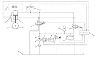
図1に示されるように、本発明の実施例で開示されるアクティブパッシブデュアルモード切換可能車両サスペンションシステムは、フィルター1、油圧ポンプ2、逆止弁3、動力取出装置4、サーボバルブ6、サスペンションタンク7、リリーフ弁9、アキュムレータ10、逆転弁11、第一圧力センサ12、第二圧力センサ13、コントローラ14、オイルタンク15、及び変位センサ16を含む。
As shown in FIG. 1, an active-passive dual-mode switchable vehicle suspension system disclosed in an embodiment of the present invention includes a
フィルター1の給油口はオイルパイプを介してオイルタンク15に連結され、フィルター1の出油口はオイルパイプを介して油圧ポンプ2の給油口に連結され、油圧ポンプ2の出油口はオイルパイプを介して逆止弁3の給油口に連結され、逆止弁3の出油口はオイルパイプを介してサーボバルブの給油口P1に連結され、サーボバルブの油戻口T1はオイルパイプを介してオイルタンク15に連結されている。
The oil supply port of the
油圧ポンプ2の駆動軸は機械構造を介して動力取出装置4に連結され、動力取出装置4は車両エンジン5の動力取出装置の出力軸に連結され、動力取出装置4は、車両エンジン5から動力を獲得し、油圧ポンプ2に伝達するためのものである。
The drive shaft of the hydraulic pump 2 is connected via a mechanical structure to a power take off device 4, the power take off device 4 is connected to the output shaft of the power take off device of the
サーボバルブの第一作動油口A1はサスペンションタンク7のロッドレスシリンダに連結され、サーボバルブの第二作動油口B1はサスペンションタンク7のロッド付きシリンダに連結されている。 The first hydraulic fluid port A1 of the servo valve is connected to the rodless cylinder of the suspension tank 7, and the second hydraulic fluid port B1 of the servo valve is connected to the rod-equipped cylinder of the suspension tank 7.
サスペンションタンク7は車体8に枢結され、サスペンションタンク7には、油圧シリンダに対するピストンロッドの変位量をモニターするための変位センサ16が設置されている。
リリーフ弁9の給油口はオイルパイプを介して逆止弁3の出油口に連結され、リリーフ弁9の出油口はオイルパイプを介してオイルタンク15に連結されている。
The suspension tank 7 is pivotally connected to the vehicle body 8, and the suspension tank 7 is provided with a
The oil supply port of the relief valve 9 is connected to the oil outlet of the check valve 3 via an oil pipe, and the oil outlet of the relief valve 9 is connected to the
逆転弁11とサーボバルブ6は並列に設置され、逆転弁の給油口P2はオイルパイプを介してオイルタンク15に連結され、逆転弁油戻口T2はオイルパイプを介してリリーフ弁9の給油口に連結され、逆転弁第一作動油口A2はオイルパイプを介してサスペンションタンク7のロッド付きシリンダに連結され、逆転弁の第二作動油口B2はオイルパイプを介してサスペンションタンク7のロッドレスシリンダに連結されている。
The reversing
アキュムレータ10は逆転弁の油戻口T2とリリーフ弁9の給油口の間の油経路に設置され、アキュムレータ10はアクティブサスペンションシステムの補助動力取出装置源として使用でき、パッシブサスペンションシステムの弾性素子としても使用できる。
The
アキュムレータ10と逆転弁の油戻口T2の間の油経路において、アキュムレータ10における油圧を検出するための第一圧力センサ12が設置されている。サスペンションタンク7のロッドレスシリンダとサーボバルブの第一作動油口A1の間の油経路において、サスペンションタンク7のロッドレスシリンダにおける油圧を検出するための第二圧力センサ13が設置されている。
A
動力取出装置4の制御端、サーボバルブ6の制御端、リリーフ弁9の制御端、及び逆転弁11の制御端は、いずれもコントローラ14に連結され、それらの信号はいずれもコントローラ14から送り出される。
The control end of the power take-off device 4, the control end of the
サーボバルブ6は3位置4ポート電気油圧サーボバルブであり、左位置、中位置、右位置の3つの状態を含む。サーボバルブ6が中位置にある時、サーボバルブの給油口P1及び油戻口T1とサーボバルブの第一作動油口A1及び第二作動油口B1との間のすべての通路が切断される。サーボバルブ6が左位置にある時、サーボバルブの給油口P1とその第一作動油口A1の間の通路が導通され、サーボバルブの油戻口T1とその第二作動油口B1の間の通路が導通され、この時、油はサーボバルブの給油口P1とその第一作動油口A1を通って、サスペンションタンク7のロッドレスシリンダに入ることができ、同時に、サスペンションタンク7のロッド付きシリンダにおける油は、サーボバルブ第二作動油口B1とその油戻口T1を通って、オイルタンク15に戻ることができる。サーボバルブ6が右位置にある時、サーボバルブの給油口P1とその第二作動油口B1の間の通路が導通され、サーボバルブの油戻口T1とその第一作動油口A1の間の通路が導通され、この時、油はサーボバルブの給油口P1とその第二作動油口B1を通って、サスペンションタンク7のロッド付きシリンダに入ることができ、同時に、サスペンションタンク7のロッドレスシリンダにおける油は、サーボバルブの第一作動油口A1とその油戻口T1を通って、オイルタンク15に戻ることができる。
リリーフ弁9は比例リリーフ弁である。リリーフ弁9の開放圧力の大きさは、コントローラ14からリリーフ弁9の制御端に制御信号を送ることにより調節され、リリーフ弁9は、アクティブサスペンションシステムの安全弁として使用でき、パッシブサスペンションシステムの安全弁としても使用できる。
Relief valve 9 is a proportional relief valve. The magnitude of the opening pressure of the relief valve 9 is adjusted by sending a control signal from the
逆転弁11は2位置4ポート電磁気逆転弁であり、切断と導通の2つの状態を含む。逆転弁11が切断状態にある時、逆転弁給油口P2及びその油戻口T2と逆転弁の第一作動油口A2及び第二作動油口B2の間のすべての通路は切断される。逆転弁11が導通状態にある時、逆転弁給油口P2とその第一作動油口A2の間の通路及び逆転弁油戻口とその第二作動油口B2の間の通路はすべて導通される。サスペンションタンク7のロッドレスシリンダにおける油は、逆転弁の第二作動油口B2と逆転弁の油戻口T2を通って、アキュムレータ10に流れることができ、オイルタンク15における油は、逆転弁の給油口P2と逆転弁の第一作動油口A2を通って、サスペンションタンク7のロッド付きシリンダに流れることができる。逆に、アキュムレータ10における油も、逆転弁の油戻口T2と逆転弁の第二作動油口B2を通って、サスペンションタンク7のロッドレスシリンダに流れることができ、サスペンションタンク7のロッド付きシリンダにおける油も、逆転弁の第一作動油口A2と逆転弁の給油口P2を通って、オイルタンク15に流れることができる。
The reversing
本発明のアクティブパッシブデュアルモード切換可能車両サスペンションシステムにおいて、システムがアクティブサスペンションモードで動作する時、動作部品は、フィルター1、油圧ポンプ2、逆止弁3、動力取出装置4、サーボバルブ6、サスペンションタンク7、リリーフ弁9、アキュムレータ10、コントローラ14、オイルタンク15、及び変位センサ16を含む。システムがパッシブサスペンションモードで動作する時、動作部品は、サスペンションタンク7、リリーフ弁9、アキュムレータ10、逆転弁11、及びオイルタンク15を含む。
In the active-passive dual-mode switchable vehicle suspension system of the present invention, when the system operates in active suspension mode, the operating components are:
アクティブサスペンションモードでは、動力取出装置4が信号を取得し、車両エンジン5の動力取出装置の出力軸に継続的に連結し、油圧ポンプ2を駆動させる。サーボバルブ6の制御端がコントローラ14の制御信号を取得し、継続的に動作する。リリーフ弁9は、開放圧力をpa(paはアクティブサスペンションシステムの安全動作の最大圧力である)のままで維持する。この時、逆転弁11が信号を得ず、切断状態を維持する。
In active suspension mode, the power take-off device 4 receives a signal and continuously connects to the power take-off output shaft of the
パッシブサスペンションモードでは、動力取出装置4が信号を得ず、車両エンジン5の動力取出装置の出力軸と切断する。サーボバルブ6が信号を得ず、中位置状態のままで維持する。リリーフ弁9は開放圧力をpsのままで維持する。逆転弁11が信号を取得し、導通状態のままで維持する。
In passive suspension mode, the power take off device 4 does not get a signal and disconnects from the power take off shaft of the
本発明のアクティブパッシブデュアルモード切換可能車両サスペンションシステムの切換方法は以下の通りである。 The switching method of the active-passive dual mode switchable vehicle suspension system of the present invention is as follows.
サスペンションシステムがアクティブサスペンションモードである時、逆転弁11は切断状態にあり、この時のリリーフ弁9の開放圧力はアクティブサスペンションシステムの安全動作の最大圧力paであり、動力取出装置4は車両エンジン5の動力取出装置の出力軸に連結され、そこから動力を獲得して油圧ポンプ2に出力し、油圧ポンプ2を駆動させ、コントローラ14は走行道路状況及び車体状況に応じて、対応する制御信号をサーボバルブ6の制御端に出力し、その動作をコントロールし、この時、アキュムレータ10はアクティブサスペンションシステムの補助動力源として使用され、リリーフ弁9はアクティブサスペンションシステムの安全弁として使用される。
When the suspension system is in the active suspension mode, the reversing
サスペンションシステムがパッシブサスペンションモードである時、逆転弁11は導通状態にあり、この時のリリーフ弁9の開放圧力はパッシブサスペンションシステムの安全動作の最大圧力psであり、動力取出装置4は車両エンジン5の動力取出装置の出力軸と切断し、油圧ポンプ2が作動を停止し、サーボバルブ6は中位置の状態にあり、この場合、アキュムレータ10はパッシブサスペンションシステムの弾性素子として使用され、リリーフ弁9はパッシブサスペンションシステムの安全弁として使用される。
When the suspension system is in the passive suspension mode, the reversing
S1.車両駐車でアクティブサスペンションからパッシブサスペンションに切り換える場合、コントローラ14は、変位センサのフィードバック信号に応じて、対応する変位指令をサーボバルブ6の制御端に出力し、サーボバルブ6は、サスペンションタンク7のピストンロッドの動きをそのフルストロークの中間位置に調節し、そしてコントローラ14はサーボバルブ6への信号出力を停止し、サーボバルブ6が中位置に戻り、油はサスペンションタンク7にロックされ、コントローラ14は動力取出装置4への信号出力を停止し、動力取出装置4と車両エンジン5の動力出力軸が切断され、油圧ポンプ2は運転を停止し、この時、第一圧力センサ12は、アキュムレータ内の圧力がp1であることを検出し、この圧力値信号をコントローラ14に伝達し、第二圧力センサ13はサスペンションタンク7のロッドレスシリンダ内の圧力がp2であることを検出し、この圧力値信号をコントローラ14に伝達し、コントローラ14は圧力値p1とp2を比較し、対応する調節を行い、具体的に以下の通りである。
S1. When switching from the active suspension to the passive suspension in parking the vehicle, the
(1)p1=p2であれば、コントローラ14は制御信号を逆転弁11の制御端に出力し、逆転弁11は切断状態から導通状態に切り換え、サスペンションタンク7のロッドレスシリンダとアキュムレータ10の間の油経路が導通され、サスペンションタンク7のロッド付きシリンダとオイルタンク15の間の油経路が導通され、コントローラ14は制御信号をリリーフ弁9の制御端に出力し、その開放圧力をpsに調節する。p1とp2が等しいため、逆転弁11が導通される時、圧力差がなく、アクティブサスペンションはパッシブサスペンションにスムーズに切り換えられる。この際、アキュムレータ10はパッシブサスペンションの弾性素子として使用され、リリーフ弁9はパッシブサスペンションシステムの安全弁として使用される。この場合、車両の作動運転はパッシブサスペンションモードでの運転である。
(1) If p 1 =p 2 , the
(2)p1>p2であれば、コントローラ14は制御信号をリリーフ弁9の制御端に出力し、リリーフ弁9の開放圧力をp2に調節し、油はアキュムレータ10からリリーフ弁9を介してオイルタンク15に戻り、第一圧力センサ12は、アキュムレータ10の圧力がp2まで減少することを検出すると、コントローラ14は再び制御信号をリリーフ弁9の制御端に出力し、その開放圧力をpsに調節し、そしてコントローラ14は制御信号を逆転弁11の制御端に出力し、切断状態から導通状態に切り換えられる。この際、p1=p2であるため、アクティブサスペンションはパッシブサスペンションにスムーズに切り換えられ、アキュムレータ10はパッシブサスペンションの弾性素子として使用され、リリーフ弁9はパッシブサスペンションシステムの安全弁として使用される。この場合、車両の作動運転はパッシブサスペンションモードでの運転である。
( 2 ) If p1>p2, the
(3)p2>p1であれば、コントローラ14は制御信号を動力取出装置4に出力し、動力取出装置4は再び車両エンジン5の出力軸に連結され、そこから動力を獲得して油圧ポンプ2に出力し、油圧ポンプ2が作動し、油は逆止弁3を介してアキュムレータ10に流れ、アキュムレータ10において油圧が上昇し、第一圧力センサ12は圧力がp2まで上昇することを検出すると、コントローラ14は動力取出装置4への制御信号出力を停止し、動力取出装置4と車両エンジン5の出力軸との連結が切断され、油圧ポンプ2が作動停止し、そしてコントローラ14は制御信号を逆転弁11の制御端に出力し、切断状態から導通状態に切り換えられる。この際、p1=p2であるため、アクティブサスペンションはパッシブサスペンションにスムーズに切り換えられ、アキュムレータ10はパッシブサスペンションの弾性素子として使用され、リリーフ弁9はパッシブサスペンションシステムの安全弁として使用される。この場合、車両の作動運転はパッシブサスペンションモードでの運転である。
(3) If p 2 >p 1 , the
S2.車両駐車でパッシブサスペンションからアクティブサスペンションに切り換える場合、まず、コントローラ14は逆転弁11への信号出力を停止し、逆転弁11は導通状態から切断状態に切り換え、油はサスペンションタンク7にロックされ、そしてコントローラ14は制御信号をリリーフ弁9に出力し、その開放圧力をpaに調節し、そしてコントローラ14は制御信号を動力取出装置4に出力し、動力取出装置4は車両エンジン5の出力軸に連結され、そこから動力を獲得して油圧ポンプ2に出力し、油圧ポンプ2が作動し、コントローラ14は変位センサ16のフィードバック信号に応じて、対応する変位指令をサーボバルブ6の制御端に出力し、サーボバルブ6は、サスペンションタンク7のピストンロッドの動きをそのフルストロークの中間位置に調節した後、コントローラ14はサーボバルブ6の制御端への制御信号出力を停止し、サーボバルブ6が中位置の状態に戻り、これでパッシブサスペンションはアクティブサスペンション状態にスムーズに切り換えられ、車両が作動運転し、コントローラ14は運転道路状況及び車体状況に応じて、対応する制御信号をサーボバルブ6の制御端に出力し、その動作を調節する。この際、アキュムレータ10はアクティブサスペンションの補助動力素子として使用され、リリーフ弁9はアクティブサスペンションシステムの安全弁として使用される。車両の作動運転はアクティブサスペンションモードでの運転である。
S2. When switching from the passive suspension to the active suspension when the vehicle is parked, first, the
なお、以上の実施例は単に本発明を説明するためのものであり、本発明の技術形態を制限するものではない。したがって、本明細書では、上記の実施例を参照しながら本発明を詳しく説明したが、当業者であれば、本発明を変更又は均等に置き換えることができる。本発明の趣旨及び範囲から逸脱しない技術形態及び改良は、すべて本発明の請求の範囲に含まれる。 It should be noted that the above examples are merely for explaining the present invention, and do not limit the technical form of the present invention. Therefore, although the present invention has been described in detail herein with reference to the above embodiments, those skilled in the art can modify or equivalently substitute the present invention. All technical forms and improvements that do not depart from the spirit and scope of the present invention are included in the claims of the present invention.
1 フィルター
2 油圧ポンプ
3 逆止弁
4 動力取出装置
5 車両エンジン
6 サーボバルブ
7 サスペンションタンク
8 車体
9 リリーフ弁
10 アキュムレータ、
11 逆転弁
12 第一圧力センサ
13 第二圧力センサ
14 コントローラ
15 オイルタンク
16 変位センサ
P1 サーボバルブの給油口
T1 サーボバルブの油戻口
A1 サーボバルブの第一作動油口
B1 サーボバルブの第二作動油口
P2 逆転弁の給油口
T2 逆転弁の油戻口
A2 逆転弁の第一作動油口
B2 逆転弁の第二作動油口
REFERENCE SIGNS
11 reversing
P1 Servo valve oil filler port
Oil return port of T1 servo valve
A1 Servo valve first hydraulic oil port
B1 Servo valve second hydraulic oil port
P2 Reversing valve oil filler port
T2 Reversing valve oil return port
A2 First hydraulic oil port of reversing valve
B2 Second hydraulic oil port of reversing valve
Claims (4)
前記フィルターの給油口はオイルパイプを介してオイルタンクに連結され、前記フィルターの出油口はオイルパイプを介して前記油圧ポンプの給油口に連結され、前記油圧ポンプの出油口はオイルパイプを介して前記逆止弁の給油口に連結され、前記逆止弁の出油口はオイルパイプを介して前記サーボバルブの給油口に連結され、前記サーボバルブの油戻口はオイルパイプを介して前記オイルタンクに連結され、
前記油圧ポンプの駆動軸は前記動力取出装置に連結され、前記動力取出装置は車両エンジンの動力取出装置の出力軸に連結され、
前記サーボバルブは3位置4ポート電気油圧サーボバルブであり、左位置、中位置、右位置の3つの状態を含み、前記サーボバルブの第一作動油口は前記サスペンションタンクのロッドレスシリンダに連結され、前記サーボバルブの第二作動油口は前記サスペンションタンクのロッド付きシリンダに連結されており、前記サーボバルブが中位置にある時、前記サーボバルブの給油口及び油戻口と前記サーボバルブの第一作動油口及び第二作動油口との間のすべての通路が切断され、前記サーボバルブが左位置にある時、前記サーボバルブの給油口と前記サーボバルブの第一作動油口の間の通路が導通され、前記サーボバルブの油戻口と前記サーボバルブの第二作動油口の間の通路が導通され、前記サーボバルブが右位置にある時、前記サーボバルブの給油口と前記サーボバルブの第二作動油口の間の通路が導通され、前記サーボバルブの油戻口と前記サーボバルブの第一作動油口の間の通路が導通され、
前記サスペンションタンクは車体に枢結され、前記サスペンションタンクには前記変位センサが設置されており、
前記リリーフ弁の給油口はオイルパイプを介して前記逆止弁の出油口に連結され、前記リリーフ弁の出油口はオイルパイプを介して前記オイルタンクに連結され、前記リリーフ弁の開放圧力の大きさは、前記コントローラから制御信号を前記リリーフ弁の制御端に送ることにより調節され、
前記逆転弁と前記サーボバルブは並列に設置され、前記逆転弁の給油口はオイルパイプを介して前記オイルタンクに連結され、前記逆転弁の油戻口はオイルパイプを介して前記リリーフ弁の給油口に連結され、前記逆転弁の第一作動油口はオイルパイプを介して前記サスペンションタンクのロッド付きシリンダに連結され、前記逆転弁の第二作動油口はオイルパイプを介して前記サスペンションタンクのロッドレスシリンダに連結されており、
前記アキュムレータは、前記逆転弁の油戻口と前記リリーフ弁の給油口の間の油経路に設置されており、
前記アキュムレータと前記逆転弁の油戻口の間の油経路において、第一圧力センサが設置され、前記サスペンションタンクのロッドレスシリンダと前記サーボバルブの第一作動油口の間の油経路において、第二圧力センサが設置されており、
前記コントローラの制御信号出力端はそれぞれ前記動力取出装置の制御端、前記サーボバルブの制御端、前記リリーフ弁の制御端、及び前記逆転弁の制御端に連結されていることを特徴とするアクティブパッシブデュアルモード切換可能車両サスペンションシステム。 Active-passive dual including filter, hydraulic pump, check valve, power take off, servo valve, suspension tank, relief valve, accumulator, reversing valve, first pressure sensor, second pressure sensor, controller, oil tank, and displacement sensor A switchable mode vehicle suspension system comprising:
The oil inlet of the filter is connected to an oil tank through an oil pipe, the oil outlet of the filter is connected to the oil inlet of the hydraulic pump through an oil pipe, and the oil outlet of the hydraulic pump is connected to the oil pipe. The oil outlet of the check valve is connected to the oil supply port of the check valve via an oil pipe, and the oil return port of the servo valve is connected to the oil supply port of the servo valve via an oil pipe. connected to the oil tank,
a drive shaft of the hydraulic pump is connected to the power take off device, the power take off device is connected to an output shaft of a vehicle engine power take off device;
Said servo valve is a three-position four-port electro-hydraulic servo valve, including three states of left position, middle position and right position, the first hydraulic fluid port of said servo valve is connected to the rodless cylinder of said suspension tank. , the second hydraulic oil port of the servo valve is connected to the rod-equipped cylinder of the suspension tank, and when the servo valve is at the intermediate position, the oil supply port and the oil return port of the servo valve are connected to the first hydraulic oil port of the servo valve; When all the passages between the first hydraulic fluid port and the second hydraulic fluid port are cut off and the servo valve is in the left position, A passage is established, and a passage is established between the oil return port of the servo valve and the second hydraulic oil port of the servo valve, and when the servo valve is in the right position, the oil supply port of the servo valve and the servo valve a passage between the second hydraulic oil port of the servo valve and a passage between the oil return port of the servo valve and the first hydraulic oil port of the servo valve;
The suspension tank is pivotally connected to the vehicle body, and the displacement sensor is installed in the suspension tank,
The oil supply port of the relief valve is connected to the oil outlet of the check valve through an oil pipe, the oil outlet of the relief valve is connected to the oil tank through an oil pipe, and the opening pressure of the relief valve is is adjusted by sending a control signal from the controller to the control end of the relief valve;
The reversing valve and the servo valve are installed in parallel, the oil supply port of the reversing valve is connected to the oil tank through an oil pipe, and the oil return port of the reversing valve is oil supply to the relief valve through an oil pipe. A first hydraulic fluid port of the reversing valve is connected to a cylinder with a rod of the suspension tank via an oil pipe, and a second hydraulic fluid port of the reversing valve is connected to the suspension tank via an oil pipe. It is connected to a rodless cylinder,
The accumulator is installed in an oil path between the oil return port of the reversing valve and the oil supply port of the relief valve,
A first pressure sensor is installed in the oil path between the accumulator and the oil return port of the reversing valve, and a second pressure sensor is installed in the oil path between the rodless cylinder of the suspension tank and the first hydraulic oil port of the servo valve. Two pressure sensors are installed,
The control signal output ends of the controller are respectively connected to the control end of the power take-off device, the control end of the servo valve, the control end of the relief valve, and the control end of the reversing valve. Dual mode switchable vehicle suspension system.
車両駐車で、アクティブサスペンションからパッシブサスペンションに切り換える場合、前記コントローラは、前記変位センサのフィードバック信号に応じて、対応する変位指令を前記サーボバルブの制御端に出力し、前記サーボバルブは、前記サスペンションタンクのピストンロッドの動きをそのフルストロークの中間位置に調節し、そして前記コントローラは前記サーボバルブへの信号出力を停止し、前記サーボバルブは中位置の状態に戻り、油は前記サスペンションタンクにロックされ、前記コントローラは前記動力取出装置への信号出力を停止し、前記動力取出装置と前記車両エンジンの動力取出装置の出力軸が切断され、前記油圧ポンプは運転を停止し、この時、前記第一圧力センサは、前記アキュムレータ内の圧力値がp1であることを検出し、前記アキュムレータ内の圧力値p1信号を前記コントローラに伝達し、前記第二圧力センサはサスペンションタンクのロッドレスシリンダ内の圧力値がp2であることを検出し、前記サスペンションタンクのロッドレスシリンダ内の圧力値p2の信号を前記コントローラに伝達し、前記コントローラは圧力値p1とp2を比較し、対応する調節を行い、具体的に以下の通りであり、
p1=p2であれば、前記コントローラは制御信号を前記逆転弁の制御端に出力し、逆転弁は切断状態から導通状態に切り換え、前記サスペンションタンクのロッドレスシリンダと前記アキュムレータの間の油経路が導通され、前記サスペンションタンクのロッド付きシリンダと前記オイルタンクの間の油経路が導通され、前記コントローラは制御信号を前記リリーフ弁の制御端に出力し、その開放圧力をパッシブサスペンションシステムの安全動作の最大圧力psに調節し、p1とp2が等しいため、逆転弁が導通される時、圧力差がなく、アクティブサスペンションはパッシブサスペンションにスムーズに切り換えられ、この際、前記アキュムレータはパッシブサスペンションの弾性素子として使用され、前記リリーフ弁はパッシブサスペンションシステムの安全弁として使用され、この場合、車両の作動運転はパッシブサスペンションモードでの運転であり、
p1>p2であれば、前記コントローラは制御信号を前記リリーフ弁の制御端に出力し、前記リリーフ弁の開放圧力をp2に調節し、油は前記アキュムレータから前記リリーフ弁を介して前記オイルタンクに戻り、前記第一圧力センサは、前記アキュムレータの圧力がp2まで減少することを検出すると、前記コントローラは再び制御信号を前記リリーフ弁の制御端に出力し、その開放圧力をパッシブサスペンションシステムの安全動作の最大圧力psに調節し、そして前記コントローラは制御信号を前記逆転弁の制御端に出力し、切断状態から導通状態に切り換えられ、この際、p1=p2であるため、アクティブサスペンションはパッシブサスペンションにスムーズに切り換えられ、前記アキュムレータはパッシブサスペンションの弾性素子として使用され、前記リリーフ弁はパッシブサスペンションシステムの安全弁として使用され、この場合、車両の作動運転はパッシブサスペンションモードでの運転であり、
p2>p1であれば、前記コントローラは制御信号を前記動力取出装置に出力し、前記動力取出装置は再び前記車両エンジンの出力軸に連結され、そこから動力を獲得して前記油圧ポンプに出力し、前記油圧ポンプが作動し、油は前記逆止弁を介して前記アキュムレータに流れ、前記アキュムレータにおいて油圧が上昇し、前記第一圧力センサは圧力がp2まで上昇することを検出すると、前記コントローラは前記動力取出装置への制御信号出力を停止し、前記動力取出装置と前記車両エンジンの出力軸との連結が切断され、前記油圧ポンプが作動停止し、そして前記コントローラは制御信号を前記逆転弁の制御端に出力し、切断状態から導通状態に切り換えられ、この際、p1=p2であるため、アクティブサスペンションはパッシブサスペンションにスムーズに切り換えられ、前記アキュムレータはパッシブサスペンションの弾性素子として使用され、前記リリーフ弁はパッシブサスペンションシステムの安全弁として使用され、この場合、車両の作動運転はパッシブサスペンションモードでの運転であり、
車両駐車で、パッシブサスペンションからアクティブサスペンションに切り換える場合、まず、前記コントローラは前記逆転弁への信号出力を停止し、前記逆転弁は導通状態から切断状態に切り換え、油はサスペンションタンクにロックされ、そして前記コントローラは制御信号を前記リリーフ弁に出力し、その開放圧力をpaに調節し、そしてコントローラは制御信号を前記動力取出装置に出力し、前記動力取出装置は前記車両エンジンの出力軸に連結され、そこから動力を獲得して前記油圧ポンプに出力し、前記油圧ポンプが作動し、前記コントローラは前記変位センサのフィードバック信号に応じて、対応する位指令を前記サーボバルブの制御端に出力し、前記サーボバルブは、サスペンションタンクのピストンロッドの動きをそのフルストロークの中間位置に調節した後、前記コントローラは前記サーボバルブの制御端への制御信号出力を停止し、前記サーボバルブは中位置の状態に戻り、これでパッシブサスペンションはアクティブサスペンション状態にスムーズに切り換えられ、車両が作動運転し、前記コントローラは運転道路状況及び車体状況に応じて、対応する制御信号を前記サーボバルブの制御端に出力し、その動作を調節し、この際、前記アキュムレータはアクティブサスペンションの補助動力素子として使用され、前記リリーフ弁はアクティブサスペンションシステムの安全弁として使用され、車両の作動運転はアクティブサスペンションモードでの運転であり、
請求項1~3のいずれか一項に記載のアクティブパッシブデュアルモード切換可能車両サスペンションシステムを利用することを特徴とする切換方法。 A switching method comprising the steps of:
When switching from the active suspension to the passive suspension in parking the vehicle, the controller outputs a corresponding displacement command to the control end of the servo valve according to the feedback signal of the displacement sensor, and the servo valve moves the suspension tank. piston rod movement to the mid-position of its full stroke, and the controller stops outputting signals to the servo-valve, the servo-valve returns to the mid-position state, and oil is locked in the suspension tank. , the controller stops outputting signals to the power take-off device, the output shafts of the power take-off device and the power take-off device of the vehicle engine are disconnected, the hydraulic pump stops operating, and at this time the first A pressure sensor detects that the pressure value in the accumulator is p1 and transmits a pressure value p1 signal in the accumulator to the controller, and the second pressure sensor detects the pressure value in the rodless cylinder of the suspension tank. detecting that the pressure value is p2 , transmitting a signal of the pressure value p2 in the rodless cylinder of the suspension tank to the controller, the controller comparing the pressure values p1 and p2 , and corresponding Adjustments are made, specifically as follows:
If p 1 =p 2 , the controller outputs a control signal to the control end of the reversing valve, the reversing valve switches from the disconnection state to the conduction state, and the oil between the rodless cylinder of the suspension tank and the accumulator is The passage is conducted, the oil passage between the rod-equipped cylinder of the suspension tank and the oil tank is conducted, the controller outputs a control signal to the control end of the relief valve, and the opening pressure is the safety of the passive suspension system. Adjusted to the maximum operating pressure p s , p 1 and p 2 are equal, so when the reversing valve is turned on, there is no pressure difference, the active suspension is smoothly switched to the passive suspension, at this time the accumulator is passive used as an elastic element of a suspension, said relief valve is used as a safety valve in a passive suspension system, in which case the active operation of the vehicle is operation in passive suspension mode;
If p1> p2 , the controller outputs a control signal to the control end of the relief valve to adjust the opening pressure of the relief valve to p2, and the oil flows from the accumulator through the relief valve to the Returning to the oil tank, when the first pressure sensor detects that the pressure of the accumulator has decreased to p2, the controller again outputs a control signal to the control end of the relief valve to set its opening pressure to the passive suspension Adjust to the maximum pressure p s of safe operation of the system, and the controller outputs a control signal to the control end of the reversing valve to switch from the disconnected state to the conductive state, because p 1 =p 2 , the active suspension is smoothly switched to the passive suspension, the accumulator is used as the elastic element of the passive suspension, and the relief valve is used as the safety valve of the passive suspension system, in which case the active operation of the vehicle is in the passive suspension mode. is driving,
If p 2 >p 1 , the controller outputs a control signal to the power take-off device, and the power take-off device is again connected to the output shaft of the vehicle engine to obtain power therefrom to the hydraulic pump. output, the hydraulic pump operates, oil flows through the check valve to the accumulator, the hydraulic pressure rises in the accumulator, the first pressure sensor detects that the pressure rises to p2, The controller stops outputting a control signal to the power take-off device, the connection between the power take-off device and the output shaft of the vehicle engine is disconnected, the hydraulic pump stops operating, and the controller outputs the control signal to the output to the control end of the reversing valve, switching from the disconnected state to the conductive state, at this time, p 1 =p 2 , so the active suspension is smoothly switched to the passive suspension, the accumulator as the elastic element of the passive suspension wherein said relief valve is used as a safety valve in a passive suspension system, wherein the vehicle's active operation is in passive suspension mode;
When switching from passive suspension to active suspension in vehicle parking, firstly, the controller stops outputting the signal to the reversing valve, the reversing valve switches from conducting state to disconnected state, oil is locked in the suspension tank, and then The controller outputs a control signal to the relief valve to adjust its opening pressure to pa, and the controller outputs a control signal to the power take-off device, which is coupled to the output shaft of the vehicle engine. power is obtained therefrom and output to the hydraulic pump, the hydraulic pump operates, and the controller outputs a corresponding displacement command to the control terminal of the servo valve according to the feedback signal of the displacement sensor. , after the servo valve adjusts the movement of the piston rod of the suspension tank to the middle position of its full stroke, the controller stops outputting the control signal to the control end of the servo valve, and the servo valve moves to the middle position; state, the passive suspension is smoothly switched to the active suspension state, the vehicle is operated, and the controller outputs a corresponding control signal to the control end of the servo valve according to the driving road conditions and vehicle conditions. and regulate its operation, at this time, the accumulator is used as an auxiliary power element of the active suspension, the relief valve is used as a safety valve of the active suspension system, and the working operation of the vehicle is operation in the active suspension mode. ,
A method of switching, characterized in that it utilizes an active-passive dual-mode switchable vehicle suspension system according to any one of claims 1-3.
Applications Claiming Priority (3)
| Application Number | Priority Date | Filing Date | Title |
|---|---|---|---|
| CN201910725158.8 | 2019-08-07 | ||
| CN201910725158.8A CN110497760B (en) | 2019-08-07 | 2019-08-07 | Active-passive dual-mode switchable vehicle suspension system and switching method thereof |
| PCT/CN2020/104512 WO2021023026A1 (en) | 2019-08-07 | 2020-07-24 | Active-passive dual mode switchable vehicle suspension system and switching method therefor |
Publications (2)
| Publication Number | Publication Date |
|---|---|
| JP2022537834A JP2022537834A (en) | 2022-08-30 |
| JP7177555B2 true JP7177555B2 (en) | 2022-11-24 |
Family
ID=68586861
Family Applications (1)
| Application Number | Title | Priority Date | Filing Date |
|---|---|---|---|
| JP2021576675A Active JP7177555B2 (en) | 2019-08-07 | 2020-07-24 | Active-passive dual-mode switchable vehicle suspension system and switching method |
Country Status (8)
| Country | Link |
|---|---|
| US (1) | US11618294B2 (en) |
| EP (1) | EP4005835B1 (en) |
| JP (1) | JP7177555B2 (en) |
| KR (1) | KR102548286B1 (en) |
| CN (1) | CN110497760B (en) |
| AU (1) | AU2020327056B2 (en) |
| CA (1) | CA3145723C (en) |
| WO (1) | WO2021023026A1 (en) |
Families Citing this family (25)
| Publication number | Priority date | Publication date | Assignee | Title |
|---|---|---|---|---|
| CN110497760B (en) * | 2019-08-07 | 2020-09-18 | 燕山大学 | Active-passive dual-mode switchable vehicle suspension system and switching method thereof |
| CN110847278B (en) * | 2019-11-28 | 2021-12-07 | 王玲芝 | Loader vibration damper |
| CN110847279B (en) * | 2019-11-28 | 2021-12-03 | 王玲芝 | Loader buffer |
| CN110836202B (en) * | 2019-12-05 | 2024-05-10 | 浙江大学 | Hydraulic source load self-adaptive system and self-adaptive control method thereof |
| CN112918500A (en) * | 2019-12-05 | 2021-06-08 | 中车唐山机车车辆有限公司 | Support mode control system and control method, rail vehicle and terminal |
| CN111852965B (en) * | 2020-06-17 | 2022-08-09 | 中国北方车辆研究所 | Pressure-displacement comprehensive control system and control method based on rocker arm suspension |
| CN111810468B (en) * | 2020-08-07 | 2024-05-14 | 秦皇岛海德科技有限公司 | Pump control hydraulic system, device and control method of turbine engine |
| CN113236617B (en) * | 2021-04-02 | 2022-02-11 | 燕山大学 | A hydraulic active suspension flow control system |
| CN113217488B (en) * | 2021-04-21 | 2024-04-26 | 沈阳海瑞琦液压科技有限公司 | System and method for measuring minimum starting pressure of hydraulic cylinder |
| US11865887B2 (en) | 2021-10-12 | 2024-01-09 | DRiV Automotive Inc. | Suspension system with incremental roll and pitch stiffness control |
| US11865889B2 (en) * | 2021-10-12 | 2024-01-09 | DRiV Automotive Inc. | Suspension system with comfort valves between cross-over hydraulic circuits |
| US12168378B2 (en) | 2021-10-12 | 2024-12-17 | DRiV Automotive Inc. | Accumulator check systems and methods |
| US11938772B2 (en) | 2021-10-12 | 2024-03-26 | DRiV Automotive Inc. | System for grading filling of a hydraulic suspension system |
| US11912092B2 (en) | 2021-10-12 | 2024-02-27 | DRiV Automotive Inc. | Suspension leak check systems and methods |
| US11919355B2 (en) | 2021-10-12 | 2024-03-05 | DRiV Automotive Inc. | Valve diagnostic systems and methods |
| US12097739B2 (en) | 2021-10-12 | 2024-09-24 | DRiV Automotive Inc. | Pump rinsing systems and methods |
| US12059937B2 (en) | 2021-10-12 | 2024-08-13 | DRiV Automotive Inc. | Suspension system with roll and pitch stiffness deactivation based on road profile information |
| CN115157949B (en) * | 2022-06-30 | 2024-09-17 | 三一汽车起重机械有限公司 | Suspension control method, suspension control system and crane |
| CN115157952A (en) * | 2022-08-31 | 2022-10-11 | 徐州徐工矿业机械有限公司 | Suspension oil cylinder hydraulic control system, adaptive oil and gas suspension system and adjustment method of suspension oil cylinder balance position |
| CN115972840B (en) * | 2022-09-30 | 2025-06-24 | 合肥工业大学 | Hydraulic interconnection suspension system and control method thereof |
| CN115597894A (en) * | 2022-10-26 | 2023-01-13 | 中国农业大学(Cn) | Test platform based on hardware-in-the-loop and oriented to agricultural machinery equipment suspension system |
| CN115783250B (en) * | 2022-12-19 | 2024-08-27 | 中国航空工业集团公司金城南京机电液压工程研究中心 | Landing gear stay bar unlocking electro-hydrostatic actuator and working method |
| CN115817805B (en) * | 2022-12-20 | 2024-08-27 | 中国航空工业集团公司金城南京机电液压工程研究中心 | Undercarriage stay bar unlocking actuator of air spring |
| CN115837823B (en) * | 2022-12-27 | 2025-05-06 | 徐工集团工程机械股份有限公司 | A hydro-pneumatic suspension system and method for improving vehicle body pitch angle and vehicle body roll angle |
| CN115903521B (en) * | 2023-02-13 | 2024-09-06 | 合肥工业大学 | Sliding mode control method of wind power generation system based on improved event triggering mechanism |
Citations (3)
| Publication number | Priority date | Publication date | Assignee | Title |
|---|---|---|---|---|
| US5195772A (en) | 1991-06-18 | 1993-03-23 | Ford Motor Company | Valve configuration for converting an active suspension system into a passive suspension system |
| CN102059929A (en) | 2010-12-20 | 2011-05-18 | 三一汽车起重机械有限公司 | Hydro-pneumatic suspension system and wheeled vehicle with same |
| CN109050192A (en) | 2018-07-19 | 2018-12-21 | 燕山大学 | Oleo-pneumatic suspension and Active Suspensions switching control circuit and hanging oil cylinder |
Family Cites Families (25)
| Publication number | Priority date | Publication date | Assignee | Title |
|---|---|---|---|---|
| JPS62289419A (en) * | 1986-06-06 | 1987-12-16 | Kayaba Ind Co Ltd | Hydro-pneumatic suspension mechanism |
| JPH0263913A (en) * | 1988-08-31 | 1990-03-05 | Kayaba Ind Co Ltd | Active suspension hydraulic control system |
| JP3179079B2 (en) * | 1989-06-22 | 2001-06-25 | 富士重工業株式会社 | Active suspension control method for vehicle |
| US5188390A (en) * | 1991-12-16 | 1993-02-23 | Ford Motor Company | Suspension system having active and passive modes |
| JP3714699B2 (en) * | 1995-03-31 | 2005-11-09 | カヤバ工業株式会社 | Variable damping force damper |
| AUPP521598A0 (en) * | 1998-08-13 | 1998-09-03 | Birrana Engineering Pty Ltd | Improved hydraulic adaptive vehicle suspension system |
| DE10106706A1 (en) * | 2001-02-14 | 2002-09-26 | Hydac Technology Gmbh | Suspension system, in particular for a work machine |
| EP1997655B1 (en) * | 2006-03-22 | 2013-05-15 | Toyota Jidosha Kabushiki Kaisha | Vehicle suspension system |
| JP5211373B2 (en) * | 2007-05-15 | 2013-06-12 | 株式会社 神崎高級工機製作所 | Dual clutch transmission for work vehicles |
| WO2010005896A1 (en) * | 2008-07-08 | 2010-01-14 | Parker-Hannifin Corporation | High pressure intensifier system |
| US20110018219A1 (en) * | 2009-07-27 | 2011-01-27 | International Truck Intellectual Property Company, Llc | Hydraulic, rigid rear axle suspension system for vehicles |
| WO2011143377A1 (en) * | 2010-05-14 | 2011-11-17 | Lord Corporation | Land vehicles and systems with controllable suspension systems |
| CN101844498B (en) * | 2010-05-28 | 2011-12-21 | 江苏大学 | Semiactive/active composite control suspension without external power source and control method thereof |
| DE102013215360B4 (en) * | 2012-09-10 | 2015-09-10 | Ford Global Technologies, Llc | Height adjustment device for vehicles with air spring and vibration damper |
| US8820064B2 (en) * | 2012-10-25 | 2014-09-02 | Tenneco Automotive Operating Company Inc. | Recuperating passive and active suspension |
| DE102013003513A1 (en) * | 2013-03-04 | 2014-09-04 | Wabco Gmbh | Compressor arrangement for operating a compressed air supply system, compressed air supply system and compressed air supply system and vehicle with such a compressed air supply system |
| US9657749B2 (en) * | 2013-03-11 | 2017-05-23 | Hydraforce, Inc. | Hydraulic suspension for vehicle and multi-functional proportional control valve for the same |
| CN104999881B (en) * | 2015-07-07 | 2018-04-06 | 湖南大学 | A kind of changeable Active control suspension of double mode |
| JP6466300B2 (en) * | 2015-09-25 | 2019-02-06 | 日立オートモティブシステムズ株式会社 | Air suspension system |
| JP6484152B2 (en) * | 2015-09-30 | 2019-03-13 | Kyb株式会社 | Suspension device |
| CN105799443B (en) | 2016-03-24 | 2018-01-23 | 中国北方车辆研究所 | The quantitative pump truck appearance regulating system of single group single-acting cylinder |
| CN206344652U (en) * | 2016-12-01 | 2017-07-21 | 上海汽车集团股份有限公司 | A kind of hydro-pneumatic suspension system of achievable active and half active switching control |
| US10358010B2 (en) * | 2017-06-05 | 2019-07-23 | Tenneco Automotive Operating Company Inc. | Interlinked active suspension |
| EP3753763B1 (en) * | 2019-06-20 | 2022-10-19 | The Dynamic Engineering Solution Pty Ltd | Vehicle suspension system |
| CN110497760B (en) * | 2019-08-07 | 2020-09-18 | 燕山大学 | Active-passive dual-mode switchable vehicle suspension system and switching method thereof |
-
2019
- 2019-08-07 CN CN201910725158.8A patent/CN110497760B/en active Active
-
2020
- 2020-07-24 CA CA3145723A patent/CA3145723C/en active Active
- 2020-07-24 AU AU2020327056A patent/AU2020327056B2/en active Active
- 2020-07-24 WO PCT/CN2020/104512 patent/WO2021023026A1/en unknown
- 2020-07-24 KR KR1020227002711A patent/KR102548286B1/en active Active
- 2020-07-24 JP JP2021576675A patent/JP7177555B2/en active Active
- 2020-07-24 EP EP20850828.3A patent/EP4005835B1/en active Active
-
2021
- 2021-10-09 US US17/497,912 patent/US11618294B2/en active Active
Patent Citations (3)
| Publication number | Priority date | Publication date | Assignee | Title |
|---|---|---|---|---|
| US5195772A (en) | 1991-06-18 | 1993-03-23 | Ford Motor Company | Valve configuration for converting an active suspension system into a passive suspension system |
| CN102059929A (en) | 2010-12-20 | 2011-05-18 | 三一汽车起重机械有限公司 | Hydro-pneumatic suspension system and wheeled vehicle with same |
| CN109050192A (en) | 2018-07-19 | 2018-12-21 | 燕山大学 | Oleo-pneumatic suspension and Active Suspensions switching control circuit and hanging oil cylinder |
Also Published As
| Publication number | Publication date |
|---|---|
| CN110497760A (en) | 2019-11-26 |
| US11618294B2 (en) | 2023-04-04 |
| WO2021023026A1 (en) | 2021-02-11 |
| US20220097471A1 (en) | 2022-03-31 |
| EP4005835A4 (en) | 2022-09-28 |
| AU2020327056B2 (en) | 2025-04-10 |
| CA3145723A1 (en) | 2021-02-11 |
| NZ784377A (en) | 2024-08-30 |
| JP2022537834A (en) | 2022-08-30 |
| CA3145723C (en) | 2023-08-08 |
| EP4005835A1 (en) | 2022-06-01 |
| AU2020327056A1 (en) | 2022-02-17 |
| KR20220047758A (en) | 2022-04-19 |
| CN110497760B (en) | 2020-09-18 |
| KR102548286B1 (en) | 2023-06-26 |
| EP4005835C0 (en) | 2023-06-07 |
| EP4005835B1 (en) | 2023-06-07 |
Similar Documents
| Publication | Publication Date | Title |
|---|---|---|
| JP7177555B2 (en) | Active-passive dual-mode switchable vehicle suspension system and switching method | |
| US6102150A (en) | Vehicle steering mechanism | |
| EP1379399B1 (en) | Vehicle roll control system | |
| JP2009023650A (en) | Vehicle roll control system | |
| US20160238041A1 (en) | Hydraulic Pressure Circuit and Working Machine | |
| JP2000085606A (en) | Steering system for automobile | |
| EP2934985B1 (en) | A power steering system for a vehicle | |
| JP2007046790A (en) | Actuation system | |
| CN102951198A (en) | Vehicle and hydraulic steering driving system | |
| CN111071436B (en) | Mechanical-hydraulic aircraft front wheel turning anti-swing system | |
| CN110304137B (en) | Hydraulic system and crane | |
| KR20190016031A (en) | Series hydraulic hybrid system for a vehicle and method of operating a series hydraulic hybrid system for a vehicle | |
| JP2008521692A (en) | Active chassis stabilization system | |
| CN110285102B (en) | Hydraulic steering control system for multi-axle emergency rescue vehicle with active suspension | |
| US7748720B2 (en) | Vehicle roll control system | |
| CN216508566U (en) | Steering system for vehicle with independent axle and vehicle | |
| WO2018032017A1 (en) | Hydraulic actuator control system | |
| CN211202470U (en) | Integrated Manifold and Hydraulic System | |
| CN110873086A (en) | Integrated valve group and hydraulic system | |
| TR2022001436T2 (en) | ACTIVE-PASSIVE DUAL MODE TRANSITIONAL VEHICLE SUSPENSION SYSTEM AND RELATED TRANSITION METHOD | |
| TH2201000671A (en) | A vehicle suspension system capable of dual active-passive mode switching and a switching method for that system. | |
| NZ784377B2 (en) | Active-passive dual mode switchable vehicle suspension system and switching method therefor | |
| KR20120029791A (en) | Active Roll Stabilizer | |
| MXPA98008562A (en) | Address for vehic | |
| KR20120036650A (en) | Active roll stabilization system |
Legal Events
| Date | Code | Title | Description |
|---|---|---|---|
| A621 | Written request for application examination |
Free format text: JAPANESE INTERMEDIATE CODE: A621 Effective date: 20211223 |
|
| A871 | Explanation of circumstances concerning accelerated examination |
Free format text: JAPANESE INTERMEDIATE CODE: A871 Effective date: 20220921 |
|
| TRDD | Decision of grant or rejection written | ||
| A01 | Written decision to grant a patent or to grant a registration (utility model) |
Free format text: JAPANESE INTERMEDIATE CODE: A01 Effective date: 20221101 |
|
| A61 | First payment of annual fees (during grant procedure) |
Free format text: JAPANESE INTERMEDIATE CODE: A61 Effective date: 20221104 |
|
| R150 | Certificate of patent or registration of utility model |
Ref document number: 7177555 Country of ref document: JP Free format text: JAPANESE INTERMEDIATE CODE: R150 |