JP7164914B1 - Load drop prevention device and load drop prevention sheet - Google Patents
Load drop prevention device and load drop prevention sheet Download PDFInfo
- Publication number
- JP7164914B1 JP7164914B1 JP2022083791A JP2022083791A JP7164914B1 JP 7164914 B1 JP7164914 B1 JP 7164914B1 JP 2022083791 A JP2022083791 A JP 2022083791A JP 2022083791 A JP2022083791 A JP 2022083791A JP 7164914 B1 JP7164914 B1 JP 7164914B1
- Authority
- JP
- Japan
- Prior art keywords
- sheet
- load
- frame
- main body
- longitudinal
- Prior art date
- Legal status (The legal status is an assumption and is not a legal conclusion. Google has not performed a legal analysis and makes no representation as to the accuracy of the status listed.)
- Active
Links
Images


Landscapes
- Body Structure For Vehicles (AREA)
- Loading Or Unloading Of Vehicles (AREA)
Abstract
【課題】簡易な構造でありながらも、荷台からの積載物のこぼれ落ちをより確実に抑制することが可能な積載物落下防止装置および積載物落下防止シートを提供する。
【解決手段】ダンプトラック10の荷台104に積載された積載物Xの外部への落下を防止するための積載物落下防止装置1であって、あおり板104Bに取り付けられた枠体2と、枠体2に装着されたシート部材3と、シート部材3を枠体2に固定するための結束バンド4と、を備え、シート部材3は、枠体2に被せられた本体シート部31,31Aと、本体シート部31,31Aに取り付けられた補強シート部32と、を有し、枠体2があおり板104上に立設した状態において、補強シート部32が、荷台104の内側に配置された状態であおり板104Bに向かって延出して、本体シート部31,31Aの固定部分を覆うと共に枠体2とあおり板104Bとの隙間を閉塞している。
【選択図】図3
A load drop prevention device and a load drop prevention sheet are provided that are capable of more reliably suppressing spillage of a load from a loading platform while having a simple structure.
A load drop prevention device 1 for preventing a load X loaded on a loading platform 104 of a dump truck 10 from falling to the outside includes a frame body 2 attached to a flap plate 104B, and a frame. The sheet member 3 attached to the body 2 and the binding band 4 for fixing the sheet member 3 to the frame 2 are provided. , and a reinforcing sheet portion 32 attached to the body sheet portions 31 and 31A, and the reinforcing sheet portion 32 is arranged inside the loading platform 104 in a state in which the frame body 2 is erected on the flap plate 104. In this state, it extends toward the flap plate 104B to cover the fixed portions of the main body sheet portions 31 and 31A and close the gap between the frame 2 and the flap plate 104B.
[Selection drawing] Fig. 3
Description
本発明は、運搬車両の荷台に積載された積載物の落下を防止するための積載物落下防止装置および積載物落下防止シートに関する。
BACKGROUND OF THE
ダンプトラックなどの運搬車両は、例えば土砂や砕石などを有底箱形状の荷台(ベッセル)に積載して運搬する。運搬車両が土砂や砕石などの積載物を荷台に積載した状態で走行すると、走行によって発生する風や振動などにより荷台から積載物が飛散したりこぼれ落ちたりする可能性がある。そのため、荷台には、積載物の飛散やこぼれ落ちを防止するための装置が備わっている。 A transport vehicle such as a dump truck transports sand, crushed stone, or the like, for example, by loading it on a bottomed box-shaped loading platform (vessel). When a transportation vehicle travels with loads such as earth and sand or crushed stones loaded on the bed, the load may scatter or spill from the bed due to wind and vibrations generated during travel. Therefore, the loading platform is equipped with a device to prevent scattering and spilling of the load.
例えば、特許文献1および特許文献2には、トラックの荷台を構成するあおり板に荷台の前後方向に沿った軸を中心軸として回動可能に立設された骨組と、骨組に取り付けられて荷台に積載された積載物を覆うシートと、を備えた荷台シート装置が開示されている。シートは、積載物が外部に露出しないよう、積載物全体を上方から覆蓋している。そのため、トラックの走行振動によって積載物が荷台の中で動き回った場合であっても、外部に飛散したりこぼれ落ちたりすることを抑制することが可能となっている。
For example,
ここで、荷台に積載される積載物の主な例として、特許文献1ではアスファルト混合物が、特許文献2では除染廃棄物が、それぞれ挙げられている。これらの積載物の場合、その一部であっても外部へ露出されることは望ましくないため、全体をシートで覆蓋する必要があった。他方、荷台に積載される積載物が土砂や砕石などの場合には、必ずしも積載物全体を覆蓋しておく必要はないため、特許文献1および特許文献2に記載されたシートよりも簡易なシートを用いて積載物の飛散やこぼれ落ちを防止しているものがある。
Here,
例えば、特許文献3には、長辺がベッセルを構成するあおり板(アオリ)の上縁に隙間を介して沿う状態でベッセル上に設置されてその長辺を回転中心として回転自在となっている管製枠組と、その管製枠組の内側に張られたシートと、を有する飛散防止装置が開示されている。シートの外縁部には、長尺の紐が挿通される複数の小穴が設けられている。そして、長尺の紐がこれらの小穴に挿通されつつ管製枠組に巻き付けられることで、管製枠組に対してシートが固定されている。管製枠組があおり板上に起立した状態では、走行風や振動によって積載物がベッセル内で動いた場合であっても積載物がシートに当たるため、ベッセルの外側に飛散せずに済む。
For example, in
特許文献1および特許文献2に記載の荷台シート装置では、シートが積載物全体を覆蓋するための構造であることから、シートの骨組への取り付けおよび固定が大掛かりになる。また、特許文献3に記載の飛散防止装置では、長尺の紐をシートに設けられた複数の小穴に挿通しつつ管製枠組に巻き付けてシートを管製枠組に固定させるため、管製枠組へのシートの取り付けに手間が掛かる。さらに、シートは管製枠組の内側に張られた状態であって、管製枠組とあおり板の上縁との間には隙間が形成された状態であるため、その隙間から積載物がこぼれ落ちてしまう可能性がある。
In the loading platform seat devices described in
そこで、本発明の目的は、簡易な構造でありながらも、荷台からの積載物のこぼれ落ちをより確実に抑制することが可能な積載物落下防止装置および積載物落下防止シートを提供することにある。 SUMMARY OF THE INVENTION Accordingly, it is an object of the present invention to provide a load drop prevention device and a load drop prevention sheet that can more reliably prevent a load from falling from a loading platform while having a simple structure. .
上記の目的を達成するために、本発明は、車両の荷台に積載された積載物の外部への落下を防止するための積載物落下防止装置であって、前記荷台の左右の側壁を構成するあおり板に取り付けられた枠体と、前記枠体に着脱可能に装着されたシート部材と、前記シート部材を前記枠体に固定するための固定部材と、を備え、前記枠体は、前記あおり板の長辺方向に沿って延在する複数の長手部と、前記複数の長手部をそれらの延在方向と交差する方向に接続する複数の短手部と、前記あおり板との取付部と、を有し、前記シート部材は、前記枠体に被せられ、一端側が他端側に向かって頂部で折り返された本体シート部と、前記本体シート部に取り付けられた補強シート部と、を有し、前記枠体が前記あおり板の上側に立設した状態において、前記複数の長手部のうち前記あおり板の側に位置する第1長手部が、前記あおり板の上端部との間に隙間を介して配置され、前記本体シート部のうち折り返し部を挟んで前記荷台の外側に面した外側領域の端部が、前記隙間を通って前記本体シート部のうち前記折り返し部を挟んで前記荷台の内側に面した内側領域の側に折り返された状態で前記固定部材により前記内側領域と固定され、前記補強シート部が、前記荷台の内側に配置された状態で前記あおり板に向かって延出して、前記外側領域と前記内側領域との固定部分を覆うと共に前記隙間を閉塞していることを特徴とする。 In order to achieve the above object, the present invention provides a cargo fall prevention device for preventing a cargo loaded on a cargo bed of a vehicle from falling to the outside, comprising left and right sidewalls of the cargo bed. A frame attached to a gate plate, a sheet member detachably attached to the frame, and a fixing member for fixing the sheet member to the frame, wherein the frame includes the gate a plurality of longitudinal portions extending along the longitudinal direction of the plate, a plurality of lateral portions connecting the plurality of longitudinal portions in a direction intersecting the direction of extension thereof, and an attachment portion for the flap plate; , wherein the sheet member includes a body sheet portion covered with the frame body and having one end folded back toward the other end at a top portion, and a reinforcing sheet portion attached to the body sheet portion. Further, in a state in which the frame is erected above the flap, a first longitudinal portion of the plurality of longitudinal portions, which is located on the flap plate side, has a gap between it and the upper end portion of the flap. and the end portion of the outer area facing the outside of the cargo bed across the folded portion of the body sheet portion passes through the gap and the cargo bed across the folded portion of the body sheet portion is fixed to the inner region by the fixing member in a state in which the reinforcing sheet portion is folded back toward the inner region side facing the inner side of the carrier, and the reinforcing sheet portion extends toward the flap plate in a state of being disposed inside the cargo bed. and covers the fixing portion between the outer region and the inner region and closes the gap.
本発明によれば、簡易な構造でありながらも、荷台からの積載物のこぼれ落ちをより確実に抑制することができる。上記した以外の課題、構成及び効果は、以下の実施形態の説明により明らかにされる。 ADVANTAGE OF THE INVENTION According to this invention, although it is a simple structure, it can suppress more reliably the spilling of the load from a loading platform. Problems, configurations, and effects other than those described above will be clarified by the following description of the embodiments.
本発明の各実施形態に係る積載物落下防止装置は、車両の荷台に積載された積載物の外部への落下を防止するための装置である。以下では、積載物落下防止装置をダンプトラックの荷台に対して用いる場合について説明する。 A load fall prevention device according to each embodiment of the present invention is a device for preventing a load loaded on a loading platform of a vehicle from falling to the outside. In the following, a description will be given of a case in which the load drop prevention device is used for the loading platform of a dump truck.
<第1実施形態>
本発明の第1実施形態に係る積載物落下防止装置1について、図1~6を参照して説明する。
<First embodiment>
A load
(ダンプトラック10の構成)
まず、積載物落下防止装置1が適用されるダンプトラック10の構成について、図1を参照して説明する。
(Configuration of dump truck 10)
First, the configuration of a
図1は、第1実施形態に係る積載物落下防止装置1を備えたダンプトラック10の一構成例を示す外観側面図である。
FIG. 1 is an external side view showing a configuration example of a
ダンプトラック10は、車両全体を支持する車体フレーム101と、車体フレーム101の前部に回転可能に取り付けられた左右一対の前輪102Aと、車体フレーム101の後部に回転可能に取り付けられた左右一対の後輪102Bと、車体フレーム101上の前側に設けられた運転室103と、車体フレーム101上における運転室103の後側に設けられた荷台104と、を備える。なお、図1では、左右一対の前輪102Aおよび後輪102Bのうち、左側の前輪102Aおよび後輪102Bのみを示している。
The
荷台104は、運転室103の背面部に対向して立設する前壁104Aと、車両の前後方向に延びて左右の側壁を構成する一対のあおり板104Bと、一対のあおり板104Bの後端側に立設された後壁104Cと、を有する箱状容器であって、内部に土砂や砕石などの積載物を積載する。
The
荷台104は、車体フレーム101に油圧シリンダを介して上下方向に傾転可能に取り付けられている。具体的には、荷台104は、油圧シリンダが収縮することにより前部が下方に傾転して車体フレーム101上に着座する倒伏姿勢となり、油圧シリンダが伸長することにより前部が上方に傾転して車体フレーム101上に起立する起立姿勢となる。荷台104が起立姿勢になると、内部に積載されている土砂や砕石などの積載物が一度に放出される。
The
ダンプトラック10は、荷を運搬する運搬車両であり、荷台104に積載物を積載した状態で走行する。このとき、風や振動などにより荷台104から積載物が飛散したりこぼれ落ちたりする可能性がある。そのため、荷台104には、積載物の外部への飛散やこぼれ落ちを防止するための積載物落下防止装置1が設けられている。
The
(積載物落下防止装置1の全体構成)
次に、積載物落下防止装置1の全体構成について、図1に加えて、図2~5、ならびに図6Aおよび図6Bを参照して説明する。
(Overall configuration of load fall prevention device 1)
Next, the overall configuration of the load
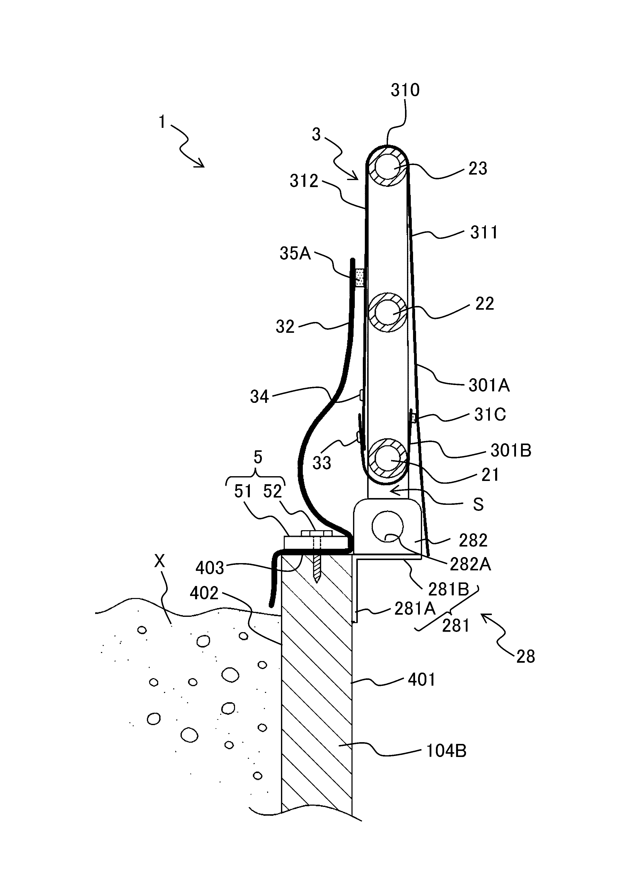
図2は、積載物落下防止装置1の一部を拡大して示す斜視図である。図3は、枠体2があおり板104B上に立設した状態の積載物落下防止装置1をダンプトラック10の前側から見た場合の断面図である。図4は、枠体2があおり板104Bの側に倒れた状態の積載物落下防止装置1をダンプトラック10の前側から見た場合の断面図である。図5は、シート部材3が取り外された状態のダンプトラック10を示す外観側面図である。図6Aは、図5におけるP部を拡大して示す側面図である。図6Bは、図5におけるP部を拡大して示す上面図である。
FIG. 2 is a perspective view showing an enlarged part of the load
積載物落下防止装置1は、あおり板104Bに取り付けられた枠体2と、枠体2に着脱可能に装着された積載物落下防止シートとしてのシート部材3と、シート部材3を枠体2に固定するための固定部材としての複数の結束バンド4と、を備える。
A load
なお、積載物落下防止装置1は、これらの各部材を左右のあおり板104Bに対応して一対ずつ備えているが、対となる各部材の構成はいずれも同一であるため、以下では、図1に示されている方、すなわち車両の左側に配置されている方の各部材の構成を例に挙げて説明する。
The load
枠体2は、図1および図5に示すように、金属製の棒状部材を加工して枠状に形成されたものであって、外枠部分が、あおり板104Bに対応した大きさを有する略長方形になっている。なお、図1では、枠体2は、シート部材3の内側に隠れた状態であるため、破線で示している。
As shown in FIGS. 1 and 5, the
本実施形態では、枠体2は、あおり板104Bの長辺方向(車両の前後方向)に沿って延在する3つの長手部21~23と、3つの長手部21~23をそれらの延在方向と交差する方向に接続する4つの短手部24~27と、が組み合わされて短冊状に形成されている。
In this embodiment, the
枠体2は、3つの取付部28によってあおり板104Bの上端部に取り付けられている。なお、本実施形態では、枠体2は、モータ(不図示)の駆動力により、あおり板104Bの長辺方向に沿った軸を中心に、あおり板104Bの上側に立設した位置(図1、図3および図5に示す位置)と、あおり板104Bとその外側で重なる位置(図4に示す位置)との間で回動することが可能となっている。
The
図1および図3に示すように、3つの長手部21~23は、例えば、中空の円形パイプで形成され、ダンプトラック10の高さ方向に所定の間隔を空けて並んで配置されている。具体的には、3つの長手部21~23のうち、第1長手部21があおり板104Bの最も近くに、第2長手部22が第1長手部21の隣りに、第3長手部23が第2長手部22の隣りに(あおり板104Bから最も離れて)、それぞれ位置している。すなわち、3つの長手部21~23は、あおり板104Bの側から第1長手部21、第2長手部22、第3長手部23の順に並んで位置している。第1長手部21と第3長手部23との間に位置する第2長手部22は、水平方向の中枠に相当する。
As shown in FIGS. 1 and 3, the three
4つの短手部24~27は、3つの長手部21~23と同様に、例えば、中空の円形パイプで形成され、図1に示すように、ダンプトラック10の前後方向に所定の間隔を空けて並んで配置されている。具体的には、4つの短手部24~27のうち、第1短手部24と第2短手部25とが、第1長手部21と第3長手部23とをそれらの長手方向の両端部で接続し、残りの第3短手部26と第4短手部27とが、第1短手部24と第2短手部25との間で第2長手部22と第3長手部23とを接続している。
Like the three
図3に示すように、3つの取付部28はそれぞれ、例えば、3つの長手部21~23および4つの短手部24~27と同様の金属材料で形成され、あおり板104Bの外側面401に固定されたブラケット281と、ブラケット281に固定されて第1長手部21が回動可能に取り付けられた本体282と、を有する。
As shown in FIG. 3, the three mounting
ブラケット281は、断面L字状であって、あおり板104Bの外側面401との固定面となる固定面部281Aと、固定面部281Aの上端からあおり板104Bの外側に向かって張り出した張り出し面部281Bと、を有する。
The
本体282は、略直方体状であって、張り出し面部281B上に固定されている。本体282には、あおり板104Bの長手方向に貫通する貫通穴282Aが形成されている。この貫通穴282Aには、第1長手部21が挿通されている。すなわち、第1長手部21は、3つの取付部28それぞれにおける本体282の貫通穴282Aに挿通されることで、本体282に対して回動自在に取り付けられている。これにより、本実施形態では、枠体2は、あおり板104Bに対してその上端部を中心として回動することが可能となっている。
The
積載物落下防止装置1は、使用する時には枠体2をあおり板104Bの上側に立設した状態で固定し(図3参照)、使用しない時には枠体2を回し下げてあおり板104Bとその外側面401で重なる状態となっている(図4参照)。したがって、図3および図4に示すように、枠体2の回動中心となる軸は、あおり板104Bを含む平面から外側に向かってオフセットしている必要がある。そのため、図3、図6A、および図6Bに示すように、枠体2があおり板104Bの上側に立設した状態では、第1長手部21とあおり板104Bの上端部との間には、所定の隙間Sが介在している。
When the load
より具体的には、隙間Sは、図6Aに示すように、第1長手部21とあおり板104Bの上端面403との間を水平方向(車体の左右方向)に貫通すると共に、図6Bに示すように、第1長手部21とあおり板104Bの外側面401との間を鉛直方向(車体の上下方向)に貫通する。
More specifically, as shown in FIG. 6A, the gap S extends horizontally (horizontal direction of the vehicle body) between the first
なお、枠体2は、必ずしもあおり板104Bに対して回動可能に取り付けられている必要はなく、あおり板104Bの上端部に隙間Sを介して立設した状態で回動不可に固定されていてもよく、ダンプトラック10の仕様に応じて適宜変更可能である。
It should be noted that the
また、本実施形態では、枠体2は、3つの長手部21~23と、4つの短手部24~27と、3つの取付部28と、を有しているが、長手部21~23および短手部24~27については、それぞれ複数であれば良く、また、必ずしも中空の円形パイプで形成されている必要はなく、取付部28については、あおり板104Bに取り付け可能であれば数および形状に関して特に制限はない。
Further, in this embodiment, the
(シート部材3の構成)
次に、シート部材3の具体的な構成について、図2~4に加えて、図7~9を参照して説明する。
(Structure of sheet member 3)
Next, a specific configuration of the
図7は、シート部材3の平面図である。図8は、シート部材3の展開図である。図9は、シート部材3の側面側断面図である。
7 is a plan view of the
シート部材3は、図2に示すように、枠体2に被せられた本体シート部31と、本体シート部31に取り付けられた補強シート部32と、を有する。
The
本体シート部31は、図2~4および図9に示すように、長方形状のシート材料であるメインシート材301Aの長辺方向の一端側が他端側に向かって頂部で折り返されることにより形成され、折り返された部分である折り返し部(頂部)310と、折り返し部310を挟んだ一側領域311と他側領域312とを接合する一対の接合部313A,313Bと、折り返し部310の反対側で開口する開口部314と、を有する。本体シート部31では、メインシート材301Aの長辺方向が短手方向となり、メインシート材301Aの短辺方向が長手方向となる。
As shown in FIGS. 2 to 4 and 9, the
なお、本体シート部31は、図8に示すように、一側領域311と他側領域312とが一対の接合部313A,313Bによって接合されて袋状に形成されていることが望ましいが、必ずしも袋状である必要はなく、少なくとも頂部で折り返されて折り返し部310を有していればよい。
In addition, as shown in FIG. 8, the
本実施形態では、本体シート部31は、特に図9に示すように、メインシート材301Aの裏面(枠体2に接触する側の面)における長辺方向の一端部に、メインシート材301Aと同一のシート材料からなる補助シート材301Bが、例えば、溶着や縫合などの接合手段により接合されている。
In the present embodiment, as shown particularly in FIG. 9, the
補助シート材301Bは、長方形状であり、長辺の長さが、メインシート材301Aの短辺の長さと同一である。図8において砂地で示すように、メインシート材301Aの長辺方向の一端部と補助シート材301Bの一側の長辺部分とが、互いの接合部31Cとなる。接合部31Cは、メインシート材301Aの短辺方向(補助シート材301Bの長辺方向)の一端から他端に亘って延在している。メインシート材301Aおよび補助シート材301Bには、例えば、防水性を有する塩化ビニル系の素材が用いられる。
The
なお、本体シート部31は、必ずしもメインシート材301Aおよび補助シート材301Bの2枚のシート材料で形成されている必要はなく、1枚のシート材料、すなわちメインシート材301Aのみで形成されていてもよい。
It should be noted that the
図3に示すように、本体シート部31は、枠体2に対して第3長手部23の側から被せられており、折り返し部310が第3長手部23の側に、開口部314が第1長手部21の側に、それぞれ位置している。
As shown in FIG. 3, the main
ここで、枠体2があおり板104B上に立設した状態において、本体シート部31の折り返し部310を挟んで荷台104の外側に面する領域を「外側領域」とし、本体シート部31の折り返し部310を挟んで荷台104の内側に面する領域を「内側領域」とする。本実施形態では、折り返し部310を挟んだ一側領域311が「外側領域」に、折り返し部310を挟んだ他側領域312が「内側領域」に、それぞれ相当する。なお、以下の説明において、「一側領域311」を「外側領域311」とし、「他側領域312」を「内側領域312」とする場合がある。
Here, in a state in which the
一対の接合部313A,313Bは、図8において砂地で示すように、本体シート部31の長手方向の両端部にて、例えば、溶着や縫合などの接合手段により、一側領域311と他側領域312とを接合している。一対の接合部313A,313Bはそれぞれ、折り返し部310からその反対側となる開口部314側に向かって延在している。
The pair of
図9に示すように、本体シート部31は、折り返し部310から一側領域311の先端(補助シート材301Bの先端)までの長さが、折り返し部310から他側領域312の先端までの長さよりも長く設定されている。すなわち、本体シート部31は、枠体2が立設した状態において、外側領域311が内側領域312よりもあおり板104Bの側に延出している。
As shown in FIG. 9, the length from the folded
図7および図8に示すように、本体シート部31の外側領域311(補助シート材301B)の先端部には、厚み方向に貫通する複数の貫通穴33が、枠体2の長手方向に沿って所定の間隔を空けて形成されている。同様にして、本体シート部31の内側領域312の先端部には、厚み方向に貫通する複数の貫通穴34が、枠体2の長手方向に沿って所定の間隔を空けて形成されている。
As shown in FIGS. 7 and 8, a plurality of through
外側領域311に形成された複数の貫通穴33と内側領域312に形成された複数の貫通穴34とは、互いに対応する位置に配置されている。これら複数の貫通穴33,34のそれぞれには、図2および図7に示すように、結束バンド4が挿通される。本体シート部31の枠体2への固定方法については、後述する。
The plurality of through
補強シート部32は、例えば、防水性を有する塩化ビニル系の素材からなる長方形状のシート材料で形成され、長辺の長さが、本体シート部31の長手方向の長さ、すなわちメインシート材301Aの短辺の長さと同一である。
The reinforcing
図2に示すように、補強シート部32は、一側の長辺部分が、本体シート部31の内側領域312の表面(荷台104の内側に露出した面)に取り付けられている。本体シート部31と補強シート部32との接合部35A(図3、図4、および図8において砂地で示す)は、枠体2の第2長手部22の位置において、その長手方向の一端から他端に亘って延在している。
As shown in FIG. 2, one long side portion of the reinforcing
なお、第2長手部22は、中枠として管製枠体を補強するものであるが、この第2長手部22に積載物Xが当たると、間に介在する本体シート部31の内側領域312を破損する可能性がある。そこで、図2に示すように、第2長手部22と本体シート部31との接触領域が補強シート部32で覆われるように、補強シート部32の接合部35Aは、第2長手部22と第3長手部23との間に位置していることが望ましい。
The second
本実施形態では、接合部35Aには、面ファスナーが用いられており、補強シート部32は、本体シート部31に対して着脱可能に取り付けられている。なお、補強シート部32は、必ずしも本体シート部31に対して着脱可能に取り付けられている必要はなく、本体シート部31に固定されていてもよい。
In this embodiment, a hook-and-loop fastener is used for the joining
また、本実施形態では、補強シート部32は、図9に示すように、シート材料の厚みT2が、本体シート部31のシート材料(メインシート材301Aおよび補助シート材301B)の厚みT1よりも厚くなっている(補強シート部32の厚みT2>本体シート部31の厚みT1)。すなわち、補強シート部32のシート材料には、本体シート部31のシート材料よりも丈夫な素材が用いられている。
Further, in the present embodiment, as shown in FIG. 9, the thickness T2 of the sheet material of the reinforcing
図2~4に示すように、補強シート部32は、本体シート部31の内側領域312よりもあおり板104Bの側に延出している。なお、図6では、補強シート部32は、本体シート部31の外側領域311の先端よりも延出しているが、これに限らず、本体シート部31の仕様によっては、本体シート部31の外側領域311が、補強シート部32の先端よりも延出していてもよい。
As shown in FIGS. 2 to 4, the reinforcing
(シート部材3の固定方法)
次に、シート部材3の固定方法について、図2、図3、および図7を参照して説明する。
(Fixing method of sheet member 3)
Next, a method for fixing the
シート部材3を枠体2に装着する際は、まず、図2および図3に示すように、あおり板104B上に枠体2が立設された状態で、本体シート部31を開口部314を介して第3長手部23の側から枠体2に被せる。このとき、補強シート部32は、図3に示すように、荷台104の内側に配置された状態であおり板104Bの内側面402に延出している。
When attaching the
次に、本体シート部31の外側領域311の先端部を、第1長手部21とあおり板104Bの上端部との間の隙間を通して、内側領域312の側に向かって折り返す。続いて、折り返された状態の外側領域311の複数の貫通穴33と内側領域312の複数の貫通穴34とに、結束バンド4をそれぞれ挿通させて外側領域311と内側領域312とを結束する。これにより、シート部材3が枠体2に固定される。このように、シート部材3は、枠体2への装着に手間の掛からない簡易な構造となっている。
Next, the tip of the
このとき、図3に示すように、補強シート部32は、本体シート部31の外側領域311と内側領域312との固定部分(複数の結束バンド4で結束されている部分)を覆うと共に、第1長手部21とあおり板104Bの上端部との間の隙間Sを閉塞している。
At this time, as shown in FIG. 3, the reinforcing
また、このとき、本実施形態では、本体シート部31のメインシート材301Aの先端部があおり板104B側に向かって延在して、隙間Sを閉塞している(図1および図3参照)。これにより、隙間Sは、外部(荷台104の外側)から見えない状態となるため、見栄えが良好となる。このように、本実施形態では、隙間Sは、荷台104の内側から補強シート部32によって閉塞されると共に、荷台104の外側から本体シート部31(メインシート材301A)によって閉塞されている。
Also, at this time, in the present embodiment, the leading end of the
続いて、本実施形態では、補強シート用の固定装置5を用いて、補強シート部32をあおり板104Bの上端面403に固定する。補強シート用の固定装置5は、あおり板104Bの長辺方向に延びる押さえ部材51と、補強シート部32をあおり板104Bに固定するための補強シート固定具としての複数のネジ52と、を有する。
Subsequently, in the present embodiment, the reinforcing
押さえ部材51は、例えば、鉄板などで形成されており、短手方向の幅が、あおり板104Bの上端面403の幅寸法と同程度の寸法に設定されている。押さえ部材51には、複数のネジ52が取り付けられる複数のネジ孔が、長手方向に所定の間隔を空けて設けられている。
The pressing
このように、本実施形態では、補強シート部32は、あおり板104Bの上端面403と押さえ部材51との間に挟まれた状態で、複数のネジ52によりあおり板104Bの上端面403に固定されているため、例えば、ダンプトラック10の走行によって発生する風などによって補強シート部32が煽られてめくれてしまうといった事態を回避することができる。
As described above, in this embodiment, the reinforcing
なお、補強シート部32の固定位置は、必ずしもあおり板104Bの上端面403である必要はなく、あおり板104Bの上端部であれば特に制限はない。あおり板104Bの上端面403以外で補強シート部32を固定する場合については、変形例として後述する。
The fixing position of the reinforcing
また、補強シート部32は、補強シート用の固定装置5によりあおり板104Bの上端部に固定されている状態において、先端部(接合部35Aとは反対側の端部)が荷台104内に積載された積載物Xにできる限り接触しないよう、短辺方向の長さが設定されていることが好ましい。仮に、補強シート部32の先端部が積載物Xとあおり板104Bの内側面402との間に挟まれていると、補強シート部32の先端部が積載物Xとの摩擦などによって摩耗しやすくなってしまう。そのため、補強シート部32を積載物Xに接触させないようにすることで、補強シート部32の摩耗を最小限に抑えることができる。
Further, the reinforcing
さらに、図3に示すように、補強シート部32は、枠体2があおり板104B上に立設した状態において、本体シート部31との接合部35Aと補強シート用の固定装置5により固定された部分との間の少なくとも一部が、荷台104の内側に向かって凸となって膨らんでいる。この膨らみがクッションの役割を担うため、荷台104内に積載された積載物Xが補強シート部32に当たった場合であっても補強シート部32の損傷を抑えることができる。
Further, as shown in FIG. 3, the reinforcing
以上のように、積載物落下防止装置1は、枠体2に対してシート部材3が装着されているだけの簡易な構造である。他方で、シート部材3は、本体シート部31の外側領域311の端部が、枠体2の第1長手部21とあおり板104Bの上端部との隙間S1を通って内側領域312の側に折り返された状態で複数の結束バンド4により内側領域312と結束されているため、ダンプトラック10の走行によって風や振動が発生した場合であっても、シート部材3が枠体2から外れにくい構造となっている。
As described above, the load
さらに、本実施形態では、シート部材3を枠体2に固定するための固定部材が複数の結束バンド4であるため、例えば、先行技術文献に挙げた特許文献3にあるように、1本の長尺の紐を巻き付けることによってシート部材3を枠体2に固定する場合と比べて、取付作業が容易である。また、1本の長尺の紐を巻き付けることによってシート部材3を枠体2に固定する場合には、紐のいずれか1箇所でも切れてしまうと、シート部材3は枠体2から外れやすくなるが、複数の結束バンド4でシート部材3を枠体2に固定する場合には、複数の結束バンド4のうちのいずれかが外れても、シート部材3は枠体2に固定された状態を維持することができる。
Furthermore, in this embodiment, since the fixing member for fixing the
また、積載物落下防止装置1は、シート部材3の補強シート部32が、荷台104の内側に配置された状態であおり板104Bの内側面402に向かって延出して、本体シート部31の外側領域311と内側領域312との固定部分(複数の結束バンド4が取り付けられた部分)を覆うと共に、枠体2の第1長手部21とあおり板104Bの上端部との隙間を閉塞しているため、補強シート部32を備えていないものに比べて、荷台104からの積載物Xの外部へのこぼれ落ちをより確実に抑制することが可能である。
In addition, in the load
さらに、本実施形態では、補強シート部32は、本体シート部31のシート材料の厚みよりも厚いシート材料で形成されているため、積載物Xである土砂や砕石などが補強シート部32に衝突した場合であっても破損しにくい。
Furthermore, in the present embodiment, since the reinforcing
なお、シート材料は、同一素材においては厚みが増すほど重量も増大するため、面積の大きい本体シート部31を厚いシート材料で形成するとシート部材3の全体の重量も増大してしまい、枠体2に対するシート部材3の着脱作業が難しくなる。そして、この問題は、荷台104が大型化するほど顕著になる。しかしながら、本実施形態のように、積載物Xが直接接触する補強シート部32のみを厚いシート材料で形成することにより、シート部材3は、全体の重量の増大を抑えながらも破損しにくい部材となる。
It should be noted that the weight of the sheet material increases as the thickness of the same material increases. It becomes difficult to attach and detach the
また、本実施形態では、補強シート部32は、面ファスナーにより本体シート部31に対して着脱可能に取り付けられているため、補強シート部32が破損したり摩耗したりした場合には、当該補強シート部32を本体シート部31から取り外して新しい補強シート部32に交換すればよく、シート部材3全体を新しいシート部材3に交換する必要がない。
Further, in the present embodiment, the reinforcing
(変形例)
次に、本発明の第1実施形態の変形例に係る積載物落下防止装置1Aについて、図10を参照して説明する。
(Modification)
Next, a load fall prevention device 1A according to a modification of the first embodiment of the present invention will be described with reference to FIG.
図10は、変形例に係る積載物落下防止装置1をダンプトラック10の前側から見た場合の断面図である。
FIG. 10 is a cross-sectional view of the load
本変形例では、図10に示すように、補強シート部32は、あおり板104Bの内側面402と押さえ部材51との間に挟まれた状態で、複数のネジ52によりあおり板104Bの内側面402に固定されている。このとき、押さえ部材51は、延伸方向の一端が、あおり板104Bの内側面402における上端に位置しており、補強シート用の固定装置5が荷台104の積載物Xにできる限り接触しないように配置されている。
In this modified example, as shown in FIG. 10, the reinforcing
このように、補強シート部32のあおり板104Bにおける固定位置は、内側面402であってもよく、この場合には、第1実施形態の場合と比べて、補強シート用の固定装置5によって補強シート部32におけるより先端部分が固定されることになるため、補強シート部32の先端部に積載物Xがより接触しにくくなる。
Thus, the fixing position of the reinforcing
<第2実施形態>
次に、本発明の第2実施形態に係る積載物落下防止装置1について、図11~14を参照して説明する。なお、図11~14において、第1実施形態に係る積載物落下防止装置1について説明したものと共通する構成要素については、同一の符号を付してその説明を省略する。
<Second embodiment>
Next, a load
図11は、第2実施形態に係る積載物落下防止装置1のシート部材3Aの一部構成を示す斜視図である。図12は、図11に示すシート部材3Aの側面側断面図である。図13は、シート部材3Aの枠体2に対する取付位置の調整方法の一例を示す図である。
FIG. 11 is a perspective view showing a partial configuration of the
本実施形態では、シート部材3Aを様々な高さの枠体2に装着可能とすべく、シート部材3Aは、枠体2に対する高さ方向(短手方向)の取付位置が調整可能となっている。
In this embodiment, the mounting position of the
図11および図12に示すように、シート部材3Aには、厚み方向に貫通して枠体2に対するシート部材3Aの取付位置を調整するための複数の調整穴36,37が、一側領域311Aおよび他側領域312Aのそれぞれに設けられている。
As shown in FIGS. 11 and 12, the
一側領域311Aに設けられた複数の調整穴36は、本体シート部31Aの短手方向に沿って折り返し部310からその反対側である開口部314側に向かって直列に3つ並び、その3つが1セットとなって本体シート部31の長手方向に所定の間隔を空けて複数セット並んでいる。
A plurality of adjustment holes 36 provided in the one-
また、本体シート部31Aの短手方向に沿って直列に並ぶ3つの調整穴36を、折り返し部310側から開口部314側に向かって順に、第1調整穴36A、第2調整穴36B、第3調整穴36Cとする。
In addition, the three
同様にして、他側領域312Aに設けられた複数の調整穴37は、本体シート部31Aの短手方向に沿って折り返し部310からその反対側である開口部314側に向かって直列に3つ並び、その3つが1セットとなって本体シート部31の長手方向に所定の間隔を空けて複数セット並んでいる。
Similarly, the plurality of adjustment holes 37 provided in the
また、一側領域311Aの複数の調整穴36と同様に、本体シート部31Aの短手方向に沿って直列に並ぶ3つの調整穴37を、折り返し部310側から開口部314側に向かって順に、第1調整穴37A、第2調整穴37B、第3調整穴37Cとする。
Also, like the plurality of adjustment holes 36 in the one-
図12に示すように、一側領域311Aの複数の調整穴36と他側領域312Aの複数の調整穴37とは、互いに対応する位置、すなわち向かい合わせの位置に配置されている。具体的には、一側領域311Aの第1調整穴36Aは他側領域312Aの第1調整穴37Aに、一側領域311Aの第2調整穴36Bは他側領域312Aの第2調整穴37Bに、一側領域311Aの第3調整穴36Cは他側領域312Aの第3調整穴37Cに、それぞれ対応している。
As shown in FIG. 12, the plurality of adjustment holes 36 in the one-
本実施形態では、一対の接合部313A,313Bは、折り返し部310から所定の間隔を空けた位置から折り返し部310とは反対側となる開口部314側に向かって延在している。したがって、図11に示すように、本体シート部31Aは、折り返し部310を含む短手方向の一端部では、長手方向の両端部が接合されていない状態となっている。
In this embodiment, the pair of
図13に示すように、枠体2に対するシート部材3Aの取付位置を調整する際には、まず、本体シート部31Aを折り返し部310側から所望の調整穴36,37の位置まで丸める。このとき、所望の調整穴36,37は、枠体2の第3長手部23のすぐ上側に位置した状態となる。そして、本体シート部31Aは、折り返し部310を含む短手方向の一端部が丸められた状態で、所望の調整穴36,37に挿通された調整用結束バンド4Aにより結束される。
As shown in FIG. 13, when adjusting the mounting position of the
図13では、調整用結束バンド4Aは、第3調整穴36C,37Cに挿通されており、シート部材3Aは、第3調整穴36C,37Cの位置で枠体2に対する取付位置が調整されている。本実施形態では、本体シート部31Aの短手方向に沿って3つの調整穴36A~C,37A~Cが所定の間隔を空けて並んでいるため、シート部材3Aは、3段階の取付位置で調整することが可能である。
In FIG. 13, the binding
なお、シート部材3Aの枠体2に対する高さ方向の取付位置の調整方法は、図13に示す方法に限られない。図14は、シート部材3Aの枠体2に対する取付位置の調整方法の他の例を示す図である。
The method of adjusting the mounting position of the
図14では、まず、本体シート部31Aの折り返し部310を枠体2の第3長手部23側に向かって谷折りにする。このとき、所望の調整穴36,37は、図13の場合と同様に、枠体2の第3長手部23のすぐ上側に位置した状態となる。図14の場合は、第1調整穴36A,37Aが第3長手部23のすぐ上側に位置した状態となっている。
In FIG. 14 , first, the folded
そして、本体シート部31Aは、折り返し部310が谷折りになった状態で、所望の調整穴36,37に挿通された調整用結束バンド4Aにより結束される。図14では、調整用結束バンド4Aは、第1調整穴36A,37Aに挿通されており、シート部材3Aは、第1調整穴36A,37Aの位置で枠体2に対する取付位置が調整される。
Then, the main
なお、シート部材3Aの枠体2に対する高さ方向の取付位置の調整は、必ずしも3段階である必要はなく、枠体2の仕様に合わせて適宜変更可能である。また、本体シート部31Aは、必ずしも調整用結束バンド4Aで結束されている必要はなく、折り返し部310を含む短手方向の一端部が丸められた状態あるいは折り返し部310が谷折りになった状態で結束することが可能なバンド部材であれば、その種類については特に制限はない。
The adjustment of the mounting position of the
このように、本実施形態では、シート部材3Aは、折り返し部310の側に短手方向の長さを調整する調整機構を有しているため、様々な高さの枠体2に装着することが可能となる。したがって、シート部材3Aを枠体2の仕様に合わせて個別に形成する必要がない。また、この調整機構は、本体シート部31Aに形成された複数の調整穴36,37と調整用結束バンド4Aとによって構成された簡易な構造であり、手間の掛からない簡単な作業でシート部材3Aの枠体2に対する取付位置を調整することができる。
As described above, in the present embodiment, the
以上、本発明の各実施形態について説明した。なお、本発明は上記した各実施形態に限定されるものではなく、様々な変形例が含まれる。例えば、上記した各実施形態は本発明を分かりやすく説明するために詳細に説明したものであり、必ずしも説明した全ての構成を備えるものに限定されるものではない。また、本実施形態の構成の一部を他の実施形態の構成に置き換えることが可能であり、また、本実施形態の構成に他の実施形態の構成を加えることも可能である。またさらに、本実施形態の構成の一部について、他の構成の追加・削除・置換をすることが可能である。 Each embodiment of the present invention has been described above. In addition, the present invention is not limited to each embodiment described above, and includes various modifications. For example, each of the above-described embodiments has been described in detail in order to explain the present invention in an easy-to-understand manner, and is not necessarily limited to those having all the described configurations. Further, part of the configuration of this embodiment can be replaced with the configuration of another embodiment, and it is also possible to add the configuration of another embodiment to the configuration of this embodiment. Furthermore, it is possible to add, delete, or replace a part of the configuration of this embodiment with another configuration.
例えば、上記実施形態では、積載物落下防止装置1が適用される車両としてダンプトラック10を例に挙げて説明したが、これに限らず、積載物を積載するための荷台104を備えた車両であれば、ダンプトラック10以外の他の車両であってもよい。
For example, in the above embodiment, the
また、上記実施形態では、シート部材3,3Aは、防水性を有する塩化ビニル系の素材からなっていたが、これに限らず、可撓性を有する素材であれば、素材自体について特に制限はない。
Further, in the above embodiment, the
1:積載物落下防止装置
2:枠体
3,3A:シート部材、積載物落下防止シート
4:結束バンド(固定部材)
4A:調整用結束バンド(バンド部材)
10:ダンプトラック(車両)
21~23:長手部
24~27:短手部
28:取付部
31,31A:本体シート部
32:補強シート部
33,34:貫通穴
36,37:調整穴
51:押さえ部材
52:ネジ(補強シート固定具)
104:荷台
104B:あおり板
310:折り返し部、頂部
311,311A:一側領域、外側領域
312,312A:他側領域、内側領域
313A,313B:接合部
314:開口部
S:隙間
1: load drop prevention device 2:
4A: Binding band for adjustment (band member)
10: Dump truck (vehicle)
21 to 23:
104:
Claims (11)
前記荷台の左右の側壁を構成するあおり板に取り付けられた枠体と、
前記枠体に着脱可能に装着されたシート部材と、
前記シート部材を前記枠体に固定するための固定部材と、を備え、
前記枠体は、
前記あおり板の長辺方向に沿って延在する複数の長手部と、
前記複数の長手部をそれらの延在方向と交差する方向に接続する複数の短手部と、
前記あおり板との取付部と、を有し、
前記シート部材は、
前記枠体に被せられ、一端側が他端側に向かって頂部で折り返された本体シート部と、
前記本体シート部に取り付けられた補強シート部と、を有し、
前記枠体が前記あおり板の上側に立設した状態において、
前記複数の長手部のうち前記あおり板の側に位置する第1長手部が、前記あおり板の上端部との間に隙間を介して配置され、
前記本体シート部のうち折り返し部を挟んで前記荷台の外側に面した外側領域の端部が、前記隙間を通って前記本体シート部のうち前記折り返し部を挟んで前記荷台の内側に面した内側領域の側に折り返された状態で前記固定部材により前記内側領域と固定され、
前記補強シート部が、前記荷台の内側に配置された状態で前記あおり板に向かって延出して、前記外側領域と前記内側領域との固定部分を覆うと共に前記隙間を閉塞している
ことを特徴とする積載物落下防止装置。 A load drop prevention device for preventing a load loaded on a vehicle bed from falling to the outside,
a frame attached to a flap that forms left and right side walls of the loading platform;
a sheet member detachably attached to the frame;
a fixing member for fixing the sheet member to the frame,
The frame is
a plurality of longitudinal portions extending along the longitudinal direction of the gate plate;
a plurality of short parts connecting the plurality of longitudinal parts in a direction intersecting with their extending direction;
and a mounting portion for the tilting plate,
The sheet member is
a body sheet portion covered with the frame body and having one end side folded back at the top portion toward the other end side;
a reinforcing sheet portion attached to the main body sheet portion;
In a state in which the frame is erected above the tilting plate,
A first longitudinal portion of the plurality of longitudinal portions located on the side of the gate plate is arranged with a gap between it and an upper end portion of the gate plate,
An end portion of an outer area of the main body sheet portion facing the outside of the cargo bed across the folded portion passes through the gap to the inner side of the main body sheet portion facing the inner side of the cargo bed across the folded portion. fixed to the inner region by the fixing member in a state of being folded back to the side of the region;
The reinforcing sheet portion is arranged inside the cargo bed and extends toward the flap plate to cover the fixed portion between the outer region and the inner region and close the gap. A load drop prevention device.
前記補強シート部は、
面ファスナーにより前記本体シート部に対して着脱可能に取り付けられている
ことを特徴とする積載物落下防止装置。 The load fall prevention device according to claim 1,
The reinforcing sheet portion is
A device for preventing the fall of a load, which is detachably attached to the sheet portion of the main body by means of a hook-and-loop fastener.
前記補強シート部は、
前記本体シート部のシート材料の厚みよりも厚いシート材料で形成されている
ことを特徴とする積載物落下防止装置。 The load fall prevention device according to claim 1,
The reinforcing sheet portion is
A device for preventing a load from falling, wherein the device is made of a sheet material that is thicker than the sheet material of the body sheet portion.
前記あおり板の長辺方向に延びる押さえ部材と、
前記補強シート部を前記あおり板に固定するための補強シート固定具と、をさらに備え、
前記補強シート部は、
前記あおり板の前記上端部と前記押さえ部材との間に挟まれた状態で前記補強シート固定具により前記あおり板の前記上端部に固定されている
ことを特徴とする積載物落下防止装置。 The load fall prevention device according to claim 1,
a pressing member extending in the long side direction of the gate plate;
a reinforcing sheet fixture for fixing the reinforcing sheet portion to the gate plate,
The reinforcing sheet portion is
A device for preventing a load from falling, wherein the device is fixed to the upper end portion of the flap plate by the reinforcing sheet fixture while being sandwiched between the upper end portion of the flap plate and the pressing member.
前記枠体は、
前記あおり板の外側において前記あおり板の長辺方向に沿って設けられた軸を中心に、前記あおり板の上側に立設した位置と、前記あおり板とその外側で重なる位置との間で回動可能に取り付けられ、
前記補強シート部は、
前記軸よりも内側において前記補強シート固定具により前記あおり板の前記上端部に固定され、
前記本体シート部との接合部分と前記補強シート固定具により固定された部分との間の長さが、前記枠体が前記あおり板の上側に立設した状態における前記補強シート部と前記本体シート部との接合部分の位置と前記補強シート固定具の固定位置との間の距離よりも長く形成されている
ことを特徴とする積載物落下防止装置。 The load fall prevention device according to claim 4,
The frame is
Rotating around an axis provided on the outer side of the flap along the longitudinal direction of the flap between a position erected on the upper side of the flap and a position overlapping the flap on the outside thereof. movably mounted,
The reinforcing sheet portion is
fixed to the upper end portion of the gate plate by the reinforcing sheet fixture inside the shaft;
The length between the joint portion with the main body sheet portion and the portion fixed by the reinforcing sheet fixing member is the reinforcing sheet portion and the main body sheet in a state in which the frame is erected above the tilting plate. A device for preventing the fall of a loaded object, characterized in that the distance between a position of a joint portion with a part and a fixing position of the reinforcing sheet fixture is longer than the distance.
前記固定部材は、
複数の結束バンドで構成され、
前記本体シート部には、
厚み方向に貫通する貫通穴が、前記固定部分となる領域に複数設けられ、
前記枠体が前記あおり板の上側に立設した状態において、
前記複数の結束バンドがそれぞれ、複数の前記貫通穴のうち前記外側領域の側の前記貫通穴と前記内側領域の側の前記貫通穴とに挿通された状態で前記外側領域と前記内側領域とを結束している
ことを特徴とする積載物落下防止装置。 The load fall prevention device according to claim 1,
The fixing member is
Consists of multiple cable ties,
In the main body seat part,
A plurality of through-holes penetrating in the thickness direction are provided in the region to be the fixed portion,
In a state in which the frame is erected above the tilting plate,
Each of the plurality of binding bands separates the outer region and the inner region while being inserted through the through hole on the outer region side and the through hole on the inner region side among the plurality of through holes. A device for preventing a load from falling, characterized by being tied.
前記枠体の前記複数の長手部は、
前記第1長手部と、
前記第1長手部の隣りに配置された第2長手部と、
前記第2長手部のさらに隣りに配置された第3長手部と、を含み、
前記補強シート部は、
前記本体シート部との接合部が前記第2長手部と前記第3長手部との間に位置し、前記第2長手部と前記本体シート部との接触領域を覆っている
ことを特徴とする積載物落下防止装置。 The load fall prevention device according to claim 1,
The plurality of longitudinal portions of the frame are
the first longitudinal portion;
a second longitudinal portion arranged adjacent to the first longitudinal portion;
a third longitudinal portion arranged further adjacent to the second longitudinal portion;
The reinforcing sheet portion is
A joint portion with the main body sheet portion is located between the second longitudinal portion and the third longitudinal portion, and covers a contact area between the second longitudinal portion and the main body sheet portion. Load fall prevention device.
前記本体シート部は、
前記折り返し部を挟んだ一側領域と他側領域とを接合する接合部を有し、
前記接合部は、
前記本体シート部における前記折り返し部の延伸方向の両端部にてそれぞれ、前記折り返し部から所定の間隔を空けた位置から前記折り返し部とは反対側に向かって延在し、
前記一側領域および前記他側領域にはそれぞれ、
厚み方向に貫通して前記枠体に対する前記シート部材の取付位置を調整するための複数の調整穴が、前記折り返し部とは反対側に向かって直列に並び、かつ、互いに対応する位置に設けられ、
前記シート部材は、
前記一側領域の側の前記調整穴と前記他側領域の側の前記調整穴とに挿通されたバンド部材が、前記本体シート部を前記折り返し部が前記枠体に向かって谷折りにされた状態で結束することにより、前記枠体に対する取付位置が調整可能となっている
ことを特徴とする積載物落下防止装置。 The load fall prevention device according to claim 1,
The main body sheet portion
Having a joint portion that joins one side region and the other side region sandwiching the folded portion,
The junction is
extending from a position spaced apart from the folded portion at a predetermined distance from the folded portion to the side opposite to the folded portion at both ends of the main body sheet portion in the extending direction of the folded portion;
In the one side area and the other side area, respectively,
A plurality of adjustment holes penetrating in the thickness direction for adjusting the mounting position of the sheet member with respect to the frame are arranged in series toward the side opposite to the folded portion and provided at positions corresponding to each other. ,
The sheet member is
The band member inserted through the adjustment hole on the side of the one side area and the adjustment hole on the side of the other side area is folded so that the main body sheet portion and the folded portion are valley-folded toward the frame. A device for preventing a load from falling, wherein a mounting position with respect to the frame can be adjusted by binding in a state.
一端側が他端側に向かって頂部で折り返された本体シート部と、
前記本体シート部における折り返し部を挟んだ一側の表面に取り付けられた補強シート部と、を備え、
前記本体シート部には、
厚み方向に貫通して前記枠体に固定するための複数の結束バンドが挿通される貫通穴が、前記折り返し部の反対側に形成された開口部の側の端部に複数設けられ、
前記補強シート部は、
先端部が前記本体シート部の前記開口部の側の前記端部よりも延出している
ことを特徴とする積載物落下防止シート。 A cargo fall prevention sheet is detachably attached to a frame attached to a flap that constitutes the left and right side walls of a cargo bed of a vehicle, and prevents a cargo loaded on the cargo bed from falling to the outside. hand,
a main body sheet part with one end side folded back toward the other end side at the top part;
a reinforcing sheet portion attached to one side surface of the body sheet portion sandwiching the folded portion,
In the main body seat part,
A plurality of through holes through which a plurality of binding bands for fixing to the frame are inserted through in the thickness direction are provided at the end on the side of the opening formed on the opposite side of the folded portion,
The reinforcing sheet portion is
A sheet for preventing a load from falling, wherein a leading end portion extends beyond the end portion of the body sheet portion on the side of the opening portion.
前記補強シート部は、
面ファスナーにより前記本体シート部に対して着脱可能に取り付けられている
ことを特徴とする積載物落下防止シート。 The load drop prevention sheet according to claim 9,
The reinforcing sheet portion is
A sheet for preventing a load from falling, characterized in that it is detachably attached to the main body sheet portion with a hook-and-loop fastener.
前記補強シート部は、
前記本体シート部のシート材料の厚みよりも厚いシート材料で形成されている
ことを特徴とする積載物落下防止シート。 The load drop prevention sheet according to claim 9,
The reinforcing sheet portion is
A sheet for preventing a load from falling, characterized by being formed of a sheet material thicker than the sheet material of the body sheet portion.
Priority Applications (1)
| Application Number | Priority Date | Filing Date | Title |
|---|---|---|---|
| JP2022083791A JP7164914B1 (en) | 2022-05-23 | 2022-05-23 | Load drop prevention device and load drop prevention sheet |
Applications Claiming Priority (1)
| Application Number | Priority Date | Filing Date | Title |
|---|---|---|---|
| JP2022083791A JP7164914B1 (en) | 2022-05-23 | 2022-05-23 | Load drop prevention device and load drop prevention sheet |
Publications (2)
| Publication Number | Publication Date |
|---|---|
| JP7164914B1 true JP7164914B1 (en) | 2022-11-02 |
| JP2023172170A JP2023172170A (en) | 2023-12-06 |
Family
ID=83887108
Family Applications (1)
| Application Number | Title | Priority Date | Filing Date |
|---|---|---|---|
| JP2022083791A Active JP7164914B1 (en) | 2022-05-23 | 2022-05-23 | Load drop prevention device and load drop prevention sheet |
Country Status (1)
| Country | Link |
|---|---|
| JP (1) | JP7164914B1 (en) |
Citations (5)
| Publication number | Priority date | Publication date | Assignee | Title |
|---|---|---|---|---|
| JPH0352336B2 (en) * | 1982-05-27 | 1991-08-09 | B & J Mfg Co | |
| JP2009029232A (en) * | 2007-07-26 | 2009-02-12 | Kurohime Co Ltd | Scattering prevention device |
| JP2015044450A (en) * | 2013-08-27 | 2015-03-12 | 日立建機株式会社 | Load dropping arrester for dump truck |
| JP2017001581A (en) * | 2015-06-12 | 2017-01-05 | 幸人 河本 | Vehicle loading platform sheet device |
| JP6652336B2 (en) | 2015-06-25 | 2020-02-19 | ダイワボウホールディングス株式会社 | Covering sheet and sheet structure used for truck truck |
-
2022
- 2022-05-23 JP JP2022083791A patent/JP7164914B1/en active Active
Patent Citations (5)
| Publication number | Priority date | Publication date | Assignee | Title |
|---|---|---|---|---|
| JPH0352336B2 (en) * | 1982-05-27 | 1991-08-09 | B & J Mfg Co | |
| JP2009029232A (en) * | 2007-07-26 | 2009-02-12 | Kurohime Co Ltd | Scattering prevention device |
| JP2015044450A (en) * | 2013-08-27 | 2015-03-12 | 日立建機株式会社 | Load dropping arrester for dump truck |
| JP2017001581A (en) * | 2015-06-12 | 2017-01-05 | 幸人 河本 | Vehicle loading platform sheet device |
| JP6652336B2 (en) | 2015-06-25 | 2020-02-19 | ダイワボウホールディングス株式会社 | Covering sheet and sheet structure used for truck truck |
Also Published As
| Publication number | Publication date |
|---|---|
| JP2023172170A (en) | 2023-12-06 |
Similar Documents
| Publication | Publication Date | Title |
|---|---|---|
| JPH04365678A (en) | Vehicle body front part structure of automobile | |
| JP7164914B1 (en) | Load drop prevention device and load drop prevention sheet | |
| JPS60218295A (en) | Crane bracket | |
| EP3940150B1 (en) | Front guard and work machine | |
| JP2023046924A (en) | Vehicle body lower part structure | |
| JPH057956Y2 (en) | ||
| JP6218047B2 (en) | Dump truck | |
| CN118339057A (en) | Seat frame | |
| JP6834659B2 (en) | Vehicle hood structure | |
| JP3927563B2 (en) | Cab and work machine | |
| JP2022057407A (en) | Battery support structure of vehicle | |
| JP3592135B2 (en) | Panel reinforcement structure | |
| JPH1193209A (en) | Swivel truck frame | |
| JP2004345486A (en) | Operator's cab reinforcing structure | |
| JPH11278300A (en) | Swivel truck frame | |
| JP2023161279A (en) | Vehicle back door structure | |
| JP5119094B2 (en) | Loader working machine | |
| JP2011143869A (en) | Cargo box | |
| JP7643313B2 (en) | Vehicle rear structure | |
| CA1238070A (en) | Spreader and dump truck | |
| JP4425385B2 (en) | Construction machinery cab with sliding door | |
| US2461653A (en) | Vehicle mounted shovel | |
| JP2004238122A (en) | Cab for construction machine | |
| JPH08324456A (en) | Body front structure | |
| JPH0396527A (en) | Support construction of operator's room |
Legal Events
| Date | Code | Title | Description |
|---|---|---|---|
| A621 | Written request for application examination |
Free format text: JAPANESE INTERMEDIATE CODE: A621 Effective date: 20220523 |
|
| A871 | Explanation of circumstances concerning accelerated examination |
Free format text: JAPANESE INTERMEDIATE CODE: A871 Effective date: 20220523 |
|
| A131 | Notification of reasons for refusal |
Free format text: JAPANESE INTERMEDIATE CODE: A131 Effective date: 20220621 |
|
| A521 | Request for written amendment filed |
Free format text: JAPANESE INTERMEDIATE CODE: A523 Effective date: 20220704 |
|
| A131 | Notification of reasons for refusal |
Free format text: JAPANESE INTERMEDIATE CODE: A131 Effective date: 20220906 |
|
| A521 | Request for written amendment filed |
Free format text: JAPANESE INTERMEDIATE CODE: A523 Effective date: 20220909 |
|
| TRDD | Decision of grant or rejection written | ||
| A01 | Written decision to grant a patent or to grant a registration (utility model) |
Free format text: JAPANESE INTERMEDIATE CODE: A01 Effective date: 20221004 |
|
| A61 | First payment of annual fees (during grant procedure) |
Free format text: JAPANESE INTERMEDIATE CODE: A61 Effective date: 20221014 |
|
| R150 | Certificate of patent or registration of utility model |
Ref document number: 7164914 Country of ref document: JP Free format text: JAPANESE INTERMEDIATE CODE: R150 |
|
| R250 | Receipt of annual fees |
Free format text: JAPANESE INTERMEDIATE CODE: R250 |