JP7163576B2 - Vehicle control system and vehicle control device - Google Patents
Vehicle control system and vehicle control device Download PDFInfo
- Publication number
- JP7163576B2 JP7163576B2 JP2017253897A JP2017253897A JP7163576B2 JP 7163576 B2 JP7163576 B2 JP 7163576B2 JP 2017253897 A JP2017253897 A JP 2017253897A JP 2017253897 A JP2017253897 A JP 2017253897A JP 7163576 B2 JP7163576 B2 JP 7163576B2
- Authority
- JP
- Japan
- Prior art keywords
- unit
- units
- output
- arithmetic
- calculation
- Prior art date
- Legal status (The legal status is an assumption and is not a legal conclusion. Google has not performed a legal analysis and makes no representation as to the accuracy of the status listed.)
- Active
Links
Images


Classifications
-
- G—PHYSICS
- G06—COMPUTING; CALCULATING OR COUNTING
- G06F—ELECTRIC DIGITAL DATA PROCESSING
- G06F11/00—Error detection; Error correction; Monitoring
- G06F11/07—Responding to the occurrence of a fault, e.g. fault tolerance
- G06F11/16—Error detection or correction of the data by redundancy in hardware
- G06F11/20—Error detection or correction of the data by redundancy in hardware using active fault-masking, e.g. by switching out faulty elements or by switching in spare elements
- G06F11/202—Error detection or correction of the data by redundancy in hardware using active fault-masking, e.g. by switching out faulty elements or by switching in spare elements where processing functionality is redundant
- G06F11/2023—Failover techniques
- G06F11/2028—Failover techniques eliminating a faulty processor or activating a spare
-
- B—PERFORMING OPERATIONS; TRANSPORTING
- B60—VEHICLES IN GENERAL
- B60W—CONJOINT CONTROL OF VEHICLE SUB-UNITS OF DIFFERENT TYPE OR DIFFERENT FUNCTION; CONTROL SYSTEMS SPECIALLY ADAPTED FOR HYBRID VEHICLES; ROAD VEHICLE DRIVE CONTROL SYSTEMS FOR PURPOSES NOT RELATED TO THE CONTROL OF A PARTICULAR SUB-UNIT
- B60W50/00—Details of control systems for road vehicle drive control not related to the control of a particular sub-unit, e.g. process diagnostic or vehicle driver interfaces
- B60W50/02—Ensuring safety in case of control system failures, e.g. by diagnosing, circumventing or fixing failures
- B60W50/029—Adapting to failures or work around with other constraints, e.g. circumvention by avoiding use of failed parts
-
- G—PHYSICS
- G06—COMPUTING; CALCULATING OR COUNTING
- G06F—ELECTRIC DIGITAL DATA PROCESSING
- G06F11/00—Error detection; Error correction; Monitoring
- G06F11/07—Responding to the occurrence of a fault, e.g. fault tolerance
- G06F11/16—Error detection or correction of the data by redundancy in hardware
- G06F11/20—Error detection or correction of the data by redundancy in hardware using active fault-masking, e.g. by switching out faulty elements or by switching in spare elements
- G06F11/202—Error detection or correction of the data by redundancy in hardware using active fault-masking, e.g. by switching out faulty elements or by switching in spare elements where processing functionality is redundant
- G06F11/2041—Error detection or correction of the data by redundancy in hardware using active fault-masking, e.g. by switching out faulty elements or by switching in spare elements where processing functionality is redundant with more than one idle spare processing component
-
- G—PHYSICS
- G06—COMPUTING; CALCULATING OR COUNTING
- G06F—ELECTRIC DIGITAL DATA PROCESSING
- G06F11/00—Error detection; Error correction; Monitoring
- G06F11/07—Responding to the occurrence of a fault, e.g. fault tolerance
- G06F11/16—Error detection or correction of the data by redundancy in hardware
- G06F11/20—Error detection or correction of the data by redundancy in hardware using active fault-masking, e.g. by switching out faulty elements or by switching in spare elements
- G06F11/202—Error detection or correction of the data by redundancy in hardware using active fault-masking, e.g. by switching out faulty elements or by switching in spare elements where processing functionality is redundant
- G06F11/2048—Error detection or correction of the data by redundancy in hardware using active fault-masking, e.g. by switching out faulty elements or by switching in spare elements where processing functionality is redundant where the redundant components share neither address space nor persistent storage
-
- B—PERFORMING OPERATIONS; TRANSPORTING
- B60—VEHICLES IN GENERAL
- B60W—CONJOINT CONTROL OF VEHICLE SUB-UNITS OF DIFFERENT TYPE OR DIFFERENT FUNCTION; CONTROL SYSTEMS SPECIALLY ADAPTED FOR HYBRID VEHICLES; ROAD VEHICLE DRIVE CONTROL SYSTEMS FOR PURPOSES NOT RELATED TO THE CONTROL OF A PARTICULAR SUB-UNIT
- B60W50/00—Details of control systems for road vehicle drive control not related to the control of a particular sub-unit, e.g. process diagnostic or vehicle driver interfaces
- B60W2050/0001—Details of the control system
- B60W2050/0002—Automatic control, details of type of controller or control system architecture
- B60W2050/0004—In digital systems, e.g. discrete-time systems involving sampling
- B60W2050/0006—Digital architecture hierarchy
-
- B—PERFORMING OPERATIONS; TRANSPORTING
- B60—VEHICLES IN GENERAL
- B60W—CONJOINT CONTROL OF VEHICLE SUB-UNITS OF DIFFERENT TYPE OR DIFFERENT FUNCTION; CONTROL SYSTEMS SPECIALLY ADAPTED FOR HYBRID VEHICLES; ROAD VEHICLE DRIVE CONTROL SYSTEMS FOR PURPOSES NOT RELATED TO THE CONTROL OF A PARTICULAR SUB-UNIT
- B60W50/00—Details of control systems for road vehicle drive control not related to the control of a particular sub-unit, e.g. process diagnostic or vehicle driver interfaces
- B60W50/02—Ensuring safety in case of control system failures, e.g. by diagnosing, circumventing or fixing failures
- B60W50/029—Adapting to failures or work around with other constraints, e.g. circumvention by avoiding use of failed parts
- B60W2050/0292—Fail-safe or redundant systems, e.g. limp-home or backup systems
Landscapes
- Engineering & Computer Science (AREA)
- Theoretical Computer Science (AREA)
- Physics & Mathematics (AREA)
- Quality & Reliability (AREA)
- General Engineering & Computer Science (AREA)
- General Physics & Mathematics (AREA)
- Automation & Control Theory (AREA)
- Transportation (AREA)
- Mechanical Engineering (AREA)
- Human Computer Interaction (AREA)
- Hardware Redundancy (AREA)
- Control Of Driving Devices And Active Controlling Of Vehicle (AREA)
- Safety Devices In Control Systems (AREA)
Description
本開示は、車両に搭載され、複数の演算部のそれぞれが他の演算部の故障の有無を認識可能に構成された車両制御システム、および車両制御装置に関する。 The present disclosure relates to a vehicle control system and a vehicle control device that are mounted on a vehicle and configured such that each of a plurality of calculation units can recognize the presence or absence of a failure in another calculation unit.
下記の特許文献1には、複数の演算部を有する車両制御システムにおいて、通常時に作動する現用系の演算部および通常時は作動せず待機する待機系の演算部を備え、現用系の演算部が故障したときに待機系の演算部が現用系の演算部の代替をすることで、制御を継続するという技術が開示されている。
ところで、システムの故障時に車両を停止させることは、高速道路上において後続車の追突による重大事故を引き起こす虞があり、あるいは、極寒・高温・乾燥などの極限環境においては人命を危険にさらす虞があり、必ずしも安全とは限らない。また、ユーザ視点として、カーディーラー等、自動車の点検整備場へ、自走で移動させたいというニーズも存在する。故に、故障部位を切り離す、あるいは、走行性能を低下させてでも、安全に自動車の走行機能を継続させられる電気・電子制御システムが求められる。
しかしながら、発明者の詳細な検討の結果、特許文献1の技術では、現用系の演算部の故障中に、待機系の演算部にも故障が発生する、いわゆる二重故障が発生した場合に、各演算部から意図しない信号が出力される可能性があり、この際には車両を安全に制御できない虞がある、という課題が見出された。
By the way, stopping a vehicle in the event of a system failure may cause a serious accident due to a rear-end collision with a following vehicle on a highway, or may endanger human life in extreme environments such as extreme cold, high temperatures, and dryness. Yes, not necessarily safe. In addition, from the user's point of view, there is also a need to move the vehicle to an automobile inspection and maintenance facility such as a car dealer by itself. Therefore, there is a demand for an electric/electronic control system that can safely continue the driving function of the automobile even if the faulty part is isolated or the driving performance is degraded.
However, as a result of a detailed study by the inventor, in the technique of
本開示の1つの局面は、車両に搭載され、3以上の演算部のそれぞれが他の2以上の演算部から故障の有無を認識可能に構成された車両制御システム、および車両制御装置において、一部の演算部に故障が発生したときに、可能な限り制御を継続できるようにしつつ、より安全に車両を制御できるような技術を提供することにある。 One aspect of the present disclosure is a vehicle control system and a vehicle control device that are mounted on a vehicle and configured such that each of three or more computing units can recognize the presence or absence of a failure from two or more other computing units. To provide a technique for safely controlling a vehicle while continuing control as much as possible when a failure occurs in an arithmetic unit of a vehicle.
本開示の一態様による車両制御システムは、故障認識部(S210,S302,S402,S502,S1302)と、制御出力部(S214,S224,S234,S313,S323,S413,S423,S513,S523,S91,S125,S1313,S1323,S1333)と、を備える。故障認識部は、当該演算部を除く他の演算部が故障していることを認識するように構成される。 A vehicle control system according to one aspect of the present disclosure includes a failure recognition unit (S210, S302, S402, S502, S1302), a control output unit (S214, S224, S234, S313, S323, S413, S423, S513, S523, S91 , S125, S1313, S1323, S1333). The fault recognizing unit is configured to recognize that other calculating units other than the relevant calculating unit are out of order.
制御出力部は、故障した演算部を故障部とし、故障していない演算部を正常部として、他の演算部のうちの予め2以上の数に設定された規定数以上の演算部が故障部である場合、予め設定されたフェールセーフ処理を実施する旨の出力を行い、他の演算部のうちの規定数未満の演算部が故障部である場合、正常部がフェールセーフ処理とは異なる車両の走行制御を実施する旨の出力を行うように構成される。 In the control output unit, the failed operation unit is defined as the failure unit, the normal operation unit is determined as the non-failed operation unit, and the operation units of the number equal to or greater than the predetermined number set to 2 or more among the other operation units are determined as the failure unit. In this case, an output indicating that a preset fail-safe process is to be performed is performed, and if less than the specified number of calculation units among the other calculation units are faulty parts, the normal part is different from the fail-safe process Vehicle It is configured to perform an output to the effect that the running control of is carried out.
このような構成によれば、3つ以上の演算部のうちの規定数未満の演算部が故障部である場合には正常部に車両の走行制御を実施させ、規定数以上の演算部が故障部である場合にはフェールセーフ処理を実施することができる。よって、可能な限り制御を継続できるようにしつつ、より安全に車両を制御することができる。 According to such a configuration, when less than the specified number of operation units out of the three or more operation units are malfunctioning units, the normal unit is caused to control the running of the vehicle, and the specified number or more of the operation units are caused to malfunction. Fail-safe processing can be implemented if it is a part. Therefore, the vehicle can be controlled more safely while the control can be continued as much as possible.
なお、この欄および特許請求の範囲に記載した括弧内の符号は、一つの態様として後述する実施形態に記載の具体的手段との対応関係を示すものであって、本開示の技術的範囲を限定するものではない。 It should be noted that the symbols in parentheses described in this column and the scope of claims indicate the correspondence with specific means described in the embodiment described later as one aspect, and the technical scope of the present disclosure is It is not limited.
以下、図面を参照しながら、本開示の実施形態を説明する。
[1.第1実施形態]
[1-1.構成]
図1に示す車両制御システム1Aは、演算部A100と、演算部B200と、演算部C300と、を備える。車両制御システム1Aは、3以上の演算部のそれぞれが他の2以上の演算部から故障の有無を監視可能に構成される。
Hereinafter, embodiments of the present disclosure will be described with reference to the drawings.
[1. First Embodiment]
[1-1. Constitution]
The
ここで、「他の2以上の演算部から故障の有無を監視可能」とは、第1実施形態のように、ある演算部が2以上の演算部から監視される構成、および後述する第2実施形態のように、ある演算部が、あるときは1つの演算部から監視され、他のときに異なる1つの演算部から監視される構成、を含む意味である。また、演算部A100,B200,C300は、それぞれが異なる電子制御装置に搭載されてもよいし、1つの電子制御装置に搭載されてもよい。 Here, the phrase "presence or absence of a failure can be monitored from two or more other computing units" means a configuration in which a certain computing unit is monitored by two or more computing units as in the first embodiment, and a second computing unit to be described later. As in the embodiment, it means that a certain computing unit is monitored by one computing unit at one time and monitored by a different one computing unit at other times. Further, the calculation units A100, B200, and C300 may be mounted in different electronic control units, or may be mounted in one electronic control unit.
また、車両制御システム1Aは、ORゲート11,ANDゲート12,13,14、ラッチ回路15,16,17を備えてもよい。
演算部A100,B200,C300は、それぞれ、CPU101,201,301と、例えば、RAM又はROM等の半導体メモリ(以下、メモリ102,202,302)と、を有するマイクロコンピュータを備える。演算部A100,B200,C300の各機能は、CPU101,201,301が非遷移的実体的記録媒体に格納されたプログラムを実行することにより実現される。この例では、メモリ102,202,302が、プログラムを格納した非遷移的実体的記録媒体に該当する。また、このプログラムが実行されることで、プログラムに対応する方法が実行される。
The
The arithmetic units A100, B200, and C300 are respectively provided with
なお、非遷移的実体的記録媒体とは、記録媒体のうちの電磁波を除く意味である。また、演算部A100,B200,C300は、1つのマイクロコンピュータを備えてもよいし、複数のマイクロコンピュータを備えてもよい。 Note that the non-transitional substantive recording medium means a recording medium excluding electromagnetic waves. Moreover, the arithmetic units A100, B200, and C300 may be provided with one microcomputer, or may be provided with a plurality of microcomputers.
また、メモリ102,202,302は、それぞれの演算部A100,B200,C300に備えられる必要はなく、演算部A100,B200,C300が、演算部A100,B200,C300の外部に配置されたメモリを共用するように構成されてもよい。
Further, the
演算部A100,B200,C300は、車両制御の機能を備える。車両制御とは、車両が有する任意の装置を制御することを表し、例えば、エンジン制御、制動制御、エアコン制御、等を含む。特に、ここでは、監視機能を含む。監視機能とは、演算部A100,B200,C300が、他の演算部が正常に作動しているか否かを監視する機能を表す。例えば、演算部A100が駆動力制御を行うユニット、演算部B200が電池制御を行うユニット、演算部C300が演算部A100および演算部B200の監視のみを行うユニットといった構成にすることができる。 The calculation units A100, B200, and C300 have a vehicle control function. Vehicle control refers to controlling any device that the vehicle has, and includes, for example, engine control, braking control, air conditioner control, and the like. In particular, it now includes a monitoring function. The monitoring function is a function of the arithmetic units A100, B200, and C300 to monitor whether other arithmetic units are operating normally. For example, it is possible to configure a unit in which the arithmetic unit A100 performs driving force control, a unit in which the arithmetic unit B200 performs battery control, and a unit in which the arithmetic unit C300 only monitors the arithmetic units A100 and B200.
監視機能では、演算部A100,B200,C300は、相互に監視を行う。これにより、任意の1つの演算部が故障したときに残りの2つの演算部が故障を検出することが可能である。また、任意の1つの演算部の故障後も、残りの2つの演算部で相互に監視を継続することが可能である。 In the monitoring function, the computing units A100, B200, and C300 monitor each other. As a result, when any one calculation unit fails, the remaining two calculation units can detect the failure. Also, even after any one of the calculation units fails, the remaining two calculation units can continue to monitor each other.
なお、ここでいう監視とは、演算部の故障を検知できる方法であれば、その手段は問わない。例えば、被監視側に基本的な演算を実行させ、監視側に結果を出力することで、演算器をチェックする方法、被監視側がウォッチドッグパルスや一定周期で動作するカウンタ等の通信データを監視側に出力し、CPUフローをチェックする方法、などがある。 It should be noted that the monitoring here means any means as long as it is a method capable of detecting a failure of the computing unit. For example, by making the monitored side perform basic calculations and outputting the results to the monitoring side, a method of checking the arithmetic unit, or a method where the monitored side monitors communication data such as watchdog pulses and counters that operate at regular intervals. There is a method of outputting to the side and checking the CPU flow.
あるいは、アプリケーションレベルで、車両制御ソフトウェアの演算結果等の制御で得られるデータを他の演算部で監視してもよい。また、相互監視を行う構成においては、一方の装置へ異常な信号、あるいは通信データを出力したときに、正しく異常判定されるか、すなわち監視機能が動いているか、を他方の装置でチェックする方法なども考えられる。 Alternatively, at the application level, data obtained by control such as calculation results of vehicle control software may be monitored by another calculation unit. In a mutual monitoring configuration, when an abnormal signal or communication data is output to one device, the other device checks whether the abnormality is correctly determined, that is, whether the monitoring function is operating. etc. can also be considered.
演算部A100,B200,C300に含まれる各部の機能を実現する手法はソフトウェアに限るものではなく、その一部又は全部の機能は、一つあるいは複数のハードウェアを用いて実現されてもよい。例えば、上記機能がハードウェアである電子回路によって実現される場合、その電子回路は、デジタル回路、又はアナログ回路、あるいはこれらの組合せによって実現されてもよい。 The method of realizing the functions of the units included in the arithmetic units A100, B200, and C300 is not limited to software, and some or all of the functions may be realized using one or more pieces of hardware. For example, when the above functions are realized by an electronic circuit that is hardware, the electronic circuit may be realized by a digital circuit, an analog circuit, or a combination thereof.
ここで、ORゲート11は、論理和を出力する周知の電子回路である。ANDゲート12,13,14は、論理積を出力する周知の電子回路である。ORゲート11は、演算部A100,B200,C300から出力されるFSxの何れかを受けると、フェールセーフ信号を出力する。
Here, the OR
ラッチ回路15,16,17は、一度ONが入力されると、ラッチ回路に対するリセット信号を受けるまで、ONの出力を継続する機能を有する周知の回路である。ラッチ回路15,16,17は、それぞれANDゲート12,13,14の出力側に配置される。
[1-2.信号]
各演算部A100,B200,C300から出力される信号について以下に説明する。各演算部A100,B200,C300には監視出力端子部を備え、この監視出力端子部からは、Wxyが出力される。Wxyは、監視結果を表す信号であり、xは信号出力元の演算部を表す番号、yは信号出力先の演算部を表す番号である。本実施形態では、演算部A100がx=1、y=1に対応し、演算部B200がx=2、y=2に対応し、演算部C300がx=3、y=3に対応する。
[1-2. signal]
Signals output from the arithmetic units A100, B200, and C300 will be described below. Each arithmetic unit A100, B200, C300 is provided with a monitor output terminal unit, and Wxy is output from this monitor output terminal unit. Wxy is a signal representing a monitoring result, x is a number representing a signal output source arithmetic unit, and y is a number representing a signal output destination arithmetic unit. In this embodiment, the calculation unit A100 corresponds to x=1 and y=1, the calculation unit B200 corresponds to x=2 and y=2, and the calculation unit C300 corresponds to x=3 and y=3.
すなわち、W12は演算部A100が判定する演算部B200の監視結果、W13は演算部A100が判定する演算部C300の監視結果である。また、W21は演算部B200が判定する演算部A100の監視結果、W23は演算部B200が判定する演算部C300の監視結果である。また、W31は演算部C300が判定する演算部A100の監視結果、W32は演算部C300が判定する演算部B200の監視結果である。 That is, W12 is the monitoring result of the computing unit B200 determined by the computing unit A100, and W13 is the monitoring result of the computing unit C300 determined by the computing unit A100. W21 is the monitoring result of the computing unit A100 determined by the computing unit B200, and W23 is the monitoring result of the computing unit C300 determined by the computing unit B200. W31 is the monitoring result of the computing unit A100 determined by the computing unit C300, and W32 is the monitoring result of the computing unit B200 determined by the computing unit C300.
各演算部A100,B200,C300は、監視する演算部の異常を検出する前は、WxyをOFFとし、監視する演算部の異常を検出すると、WxyをONにした出力をする。
また、各演算部A100,B200,C300には、RSTxが入力される入力端子部を備える。xは入力端子部を有する演算部を表す番号である。RSTxは、各演算部に入力される外部リセット信号であり、RSTxのONが入力されると演算部はリセット状態となり、演算部の全ての作動および出力が停止する。
Each of the computing units A100, B200, and C300 turns off Wxy before detecting an abnormality in the monitored computing unit, and turns on Wxy when detecting an abnormality in the monitored computing unit.
Further, each of the arithmetic units A100, B200, and C300 has an input terminal unit to which RSTx is input. x is a number representing a computing unit having an input terminal. RSTx is an external reset signal that is input to each calculation unit. When RSTx is turned ON, the calculation unit is reset, and all operations and outputs of the calculation unit are stopped.
つまり、RSTxは演算部の機能を停止させる停止指令として機能する。本実施形態では、ラッチ回路15,16,17がRSTxのONを継続するので、各演算部A100,B200,C300は、RSTxのON入力の継続により、リセット状態が継続し、信号の出力が停止する。
In other words, RSTx functions as a stop command for stopping the functions of the computing unit. In this embodiment, since the
なお、RST1は演算部A100のリセット入力、RST2は演算部B200のリセット入力、RST3は演算部C300のリセット入力である。後述するように、故障した演算部は、他の演算部から入力端子部にONが入力されることで、リセット状態となる。ここで、以下の説明では、故障した演算部を「故障部」とも表記し、また、故障していない演算部を「正常部」とも表記する。 RST1 is the reset input of the arithmetic section A100, RST2 is the reset input of the arithmetic section B200, and RST3 is the reset input of the arithmetic section C300. As will be described later, the malfunctioning computation unit enters a reset state when ON is input to the input terminal unit from another computation unit. Here, in the following description, a malfunctioning computing unit is also referred to as a "faulty unit", and a non-faulty computing unit is also referred to as a "normal unit".
なお、本案が期待する効果は、本信号のON入力により、故障した演算部が外部に異常な信号を出力しないことにあるので、リセットを継続する構成に換えて、演算部の電源カットをする効果や、全出力ポートを無効化する効果が継続する信号を採用する構成であってもよい。 The expected effect of this proposal is that the malfunctioning calculation unit does not output an abnormal signal to the outside when this signal is turned ON. A configuration that employs a signal that continues to have an effect or an effect of disabling all output ports may be employed.
次に、各演算部A100,B200,C300にはフェールセーフ出力端子部を備え、このフェールセーフ出力端子部からは、FSxが出力される。xは信号出力元の演算部を表す番号である。 Next, each of the arithmetic units A100, B200, and C300 is provided with a fail-safe output terminal section, and FSx is output from this fail-safe output terminal section. x is a number representing a signal output source calculation unit.
FS1は演算部A100からのフェールセーフ出力、FS2は演算部からのフェールセーフ出力、FS3は演算部C300からのフェールセーフ出力である。FSはORゲート11により、FS1,FS2,FS3の論理和として出力される。
FS1 is the fail-safe output from the arithmetic unit A100, FS2 is the fail-safe output from the arithmetic unit, and FS3 is the fail-safe output from the arithmetic unit C300. FS is output by the
FSは、本案で提案するシステム全体から出力されるフェールセーフ出力を表すフェールセーフ信号であり、ONが出力されたときに、フェールセーフ出力を受けた任意の制御装置が車両を安全に停止するように制御する。例えば、ハイブリッド車や電気自動車において、車両の駆動力を生み出す電動モータの駆動装置につながっており、ON出力時には、駆動装置が駆動力を強制的にカットする。 FS is a fail-safe signal that represents the fail-safe output output from the entire system proposed in this proposal. to control. For example, in a hybrid vehicle or an electric vehicle, it is connected to a driving device of an electric motor that generates the driving force of the vehicle, and the driving device forcibly cuts off the driving force at the time of ON output.
各演算部A100,B200,C300は、演算部の二重故障を検出した場合、あるいは走行機能を継続すると不安全な状態となる致命的な異常を検出した場合に、フェールセーフ信号FSxのONを出力する。ただし、本案の課題を鑑みると、演算部の故障が単一故障のみで、走行機能を継続できる場合は、フェールセーフ信号FSxはOFF出力とすることが好ましい。 Each of the arithmetic units A100, B200, and C300 turns on the fail-safe signal FSx when a double failure of the arithmetic unit is detected, or when a fatal abnormality is detected that makes it unsafe to continue the running function. Output. However, in view of the problem of the present invention, it is preferable that the fail-safe signal FSx is turned OFF when the operation unit has only a single failure and the running function can be continued.
何れかの演算部が二重故障や致命的な異常を検出した場合に、車両を安全に停止させるためには、ORゲート11が必要である。なお、各演算部A100,B200,C300は、故障発生後にRSTxによりリセットされた状態ではFSxがOFF出力となるように設定される。
The
ただし、各演算部A100,B200,C300がリセットされた状態でのFSx出力がハイインピーダンスになる場合は、FSx出力は、外部プルアップまたはプルダウンによりOFF出力となるようにしておくとよい。この構成は、単一の故障であれば、残りの演算部で走行継続させ、二重故障や致命的な異常を検出した時のみ、FSをONにするためである。 However, if the FSx output becomes high impedance in a state where each of the arithmetic units A100, B200, and C300 are reset, the FSx output should be turned off by an external pull-up or pull-down. This configuration is intended to allow the remaining operation units to continue running in the event of a single failure, and to turn on the FS only when a double failure or fatal abnormality is detected.
ここで、RST1はW21,W31を入力とするANDゲート12の出力結果であり、RST2はW12,W32を入力とするANDゲート13の出力結果であり、RST3はW13,W23を入力とするANDゲート14の出力結果である。本構成とすることで、例えば、演算部A100が故障したときには、演算部B200および演算部C300が演算部A100の故障を検出し、W21=ON,W31=ONとなるため、演算部A100をリセットさせることができ、故障している演算部A100の出力を停止できる。
Here, RST1 is the output result of the AND
なお、ANDゲート12~14が、ANDゲートではなくORゲートである場合には、例えば演算部A100の単一故障の際、W12が異常出力となり、どのような出力になるか分からない状況となる。例えば、W12がONとなってしまった場合、演算部B200が意図しないタイミングでリセットされてしまう虞がある。
If the AND
このため、本案では、リセット入力側の演算部に対し、監視結果出力側の演算部の単一故障による影響を与えないために、また、故障している演算部のみを確実にリセットさせるために、ANDゲートを備える構成を採用する。 For this reason, in this proposal, in order not to affect the reset input side calculation section due to a single failure of the monitoring result output side calculation section, and to ensure that only the faulty calculation section is reset. , AND gates.
なお、各演算部A100,B200,C300は、RSTxによりリセットされた状態ではWxyがOFF出力となるようにしておく。ただし、各演算部A100,B200,C300がリセットされた状態でのWxyの出力がハイインピーダンスになる場合は、外部プルアップまたはプルダウンによりWxyがOFF出力となるように設定する。 It should be noted that each of the calculation units A100, B200, and C300 is set so that Wxy is turned off when it is reset by RSTx. However, when the output of Wxy becomes high impedance in a state where each arithmetic unit A100, B200, C300 is reset, Wxy is set to be an OFF output by an external pull-up or pull-down.
この構成は、1つの演算部故障後の走行継続中に、2つ目の演算部が故障した時に、3つ目の正常動作している演算部が意図せずリセットされることを防ぐためである。リセット状態でWxyがOFFではなくONとなってしまう場合、例えば演算部A100が故障している状態、すなわち、W13=ONで、演算部B200の故障が発生したときに、W23が異常出力によりONとなってしまうと、正常動作している演算部C300がリセットされてしまう。リセット状態ではWxy=OFFとすることで、二重故障発生時にも3つ目の正常動作している演算部が意図せずリセットされることがなくなるようにしている。 This configuration is to prevent the third operating unit from being unintentionally reset when the second operating unit breaks down while driving continues after one of the operating units fails. be. When Wxy turns ON instead of OFF in the reset state, for example, when the calculation unit A100 is out of order, that is, when W13=ON and a failure occurs in the calculation unit B200, W23 is turned ON due to an abnormal output. , the operating unit C300, which is operating normally, is reset. By setting Wxy=OFF in the reset state, even when a double failure occurs, the third operating unit in normal operation is not unintentionally reset.
ラッチ回路15~17は、RSTx信号がOFFからONになると、OFF状態からON状態に遷移し、その後は、ANDゲート12~14の出力状態に関わらず、ON状態を保持する。本構成とすることで、1つの演算部故障後の走行継続中に、2つ目の演算部が故障した時も、1つ目の故障部はリセット状態が継続され、出力停止状態が継続する。 When the RSTx signal turns from OFF to ON, the latch circuits 15-17 transition from the OFF state to the ON state, and thereafter maintain the ON state regardless of the output states of the AND gates 12-14. With this configuration, even if the second computing unit fails while running is continued after the failure of one computing unit, the reset state of the first malfunctioning unit continues and the output stop state continues. .
なお、ラッチ回路を備えない場合は、例えば演算部A100が故障している状態で、演算部B200の故障が発生すると、W21が異常出力によりOFFとなってしまい、故障している演算部A100がリセット状態から意図せず復帰してしまう虞がある。さらに、この際、故障部からの出力であるW13,W23が異常出力によりONとなってしまうと、正常動作している演算部C300が意図せずリセットしてしまう虞がある。 If the latch circuit is not provided, for example, if the arithmetic unit B200 fails while the arithmetic unit A100 is out of order, W21 is turned off due to an abnormal output, and the malfunctioning arithmetic unit A100 There is a risk of unintended return from the reset state. Furthermore, at this time, if W13 and W23, which are outputs from the failure unit, are turned ON due to an abnormal output, there is a risk that the operating unit C300 that is operating normally may be reset unintentionally.
このため、本案では、演算部が一度リセットされたら、その後はリセット状態を保持する構成とすることで、上記のような、二重故障発生時にリセットした演算部が意図せずに復帰する虞を取り除いている。なお、ラッチ回路15~17において、ラッチ状態のクリア、すなわちリセット解除は、例えば、3つ全ての演算部が正常である場合に行うように構成する。ラッチ回路15~17は、所定のリセット信号を受けるとON状態からOFF状態に遷移する。
For this reason, in this proposal, once the operation unit is reset, the reset state is maintained after that, so that the operation unit reset when the double failure occurs can be prevented from unintentionally returning as described above. are removing. In the
[1-2.処理]
次に、各演算部A100,B200,C300が実行する監視処理について、図2以下のフローチャートを用いて説明する。監視処理では、前述の監視機能を処理として実現する。また、監視処理は、例えば、車両の電源が投入されると開始される。
[1-2. process]
Next, the monitoring process executed by each calculation unit A100, B200, C300 will be described with reference to the flow charts of FIG. 2 and subsequent figures. In the monitoring process, the monitoring function described above is implemented as a process. Also, the monitoring process is started, for example, when the power of the vehicle is turned on.
監視処理では、まず、S210で、演算部A100,B200,C300は、他の演算部に故障が発生したか否かを判定する。演算部A100,B200,C300は、他の演算部に故障が発生していない場合に、S210を繰り返す。 In the monitoring process, first, in S210, the computing units A100, B200, and C300 determine whether or not a failure has occurred in another computing unit. The calculation units A100, B200, and C300 repeat S210 when no failure occurs in other calculation units.
また、演算部B200,C300は、演算部A100が故障したと判定すると、S212に移行する。また、演算部A100,C300は、演算部B200が故障したと判定すると、S222に移行する。また、演算部A100,B200は、演算部C300が故障したと判定すると、S232に移行する。 Further, when the calculation units B200 and C300 determine that the calculation unit A100 has failed, the process proceeds to S212. Further, when the calculation units A100 and C300 determine that the calculation unit B200 has failed, the process proceeds to S222. Further, when the arithmetic units A100 and B200 determine that the arithmetic unit C300 has failed, the process proceeds to S232.
S212では、演算部A100を監視している演算部B200、および演算部C300が演算部A100の異常を検出している。この場合、演算部B200はW21をON出力し、および演算部C300はW31をON出力する。これにより、S213で示すように、RST1がONとなり、演算部A100は動作および出力が停止する。すなわち、故障している演算部A100から外部への異常な信号は全てカットされる。 In S212, the arithmetic unit B200 and the arithmetic unit C300 that monitor the arithmetic unit A100 detect an abnormality in the arithmetic unit A100. In this case, calculation unit B200 turns on W21, and calculation unit C300 turns on W31. As a result, as indicated by S213, RST1 is turned ON, and the operation and output of the arithmetic unit A100 are stopped. That is, all abnormal signals to the outside from the malfunctioning arithmetic unit A100 are cut.
続いてS214で、演算部B200およびC300は、フェールセーフ処理とは異なる車両の走行制御、例えば、演算部A100が故障していないときの制御状態を表す通常制御状態における制御を継続しつつ、演算部B200およびC300のうちの少なくとも一方は、演算部A100が実行していた車両制御を代替して実行する車両制御機能代替を開始する。この結果、演算部B200と演算部C300とが相互に監視を継続している状態で、走行を継続できる。 Subsequently, in S214, the calculation units B200 and C300 continue the vehicle running control different from the fail-safe process, for example, the control in the normal control state representing the control state when the calculation unit A100 is not malfunctioning. At least one of the units B200 and C300 starts vehicle control function substitution to substitute the vehicle control executed by the arithmetic unit A100. As a result, it is possible to continue running while the computation unit B200 and the computation unit C300 continue to monitor each other.
なお、機能代替では、通常制御状態で演算部A100が行っている制御全てをそのまま実行してもよいし、機能を縮退して走行に必要な最低限の機能のみを実行してもよい。また、演算部B200およびC300は、演算部A100の故障を受けて、通常制御状態から実行する制御を変更してもよい。また、演算部A100が故障したときに限らず、演算部B200またはC300が故障したときは、他の演算部が同様に機能してもよい。 Note that, in the function substitution, all the control performed by the arithmetic unit A100 in the normal control state may be performed as it is, or the functions may be degenerated to perform only the minimum functions required for running. Moreover, the calculation units B200 and C300 may change the control to be executed from the normal control state in response to the failure of the calculation unit A100. In addition, other calculation units may function similarly when the calculation unit B200 or C300 fails, not only when the calculation unit A100 fails.
次に、S222では、演算部B200に故障が発生しており、演算部B200を監視している演算部A100およびC300が演算部B200の異常を検出している。この場合、演算部A100は、W12をON出力し、演算部C300は、W32をON出力する。これにより、S223に示すように、RST2がONとなり、演算部B200は動作および出力が停止する。すなわち、故障している演算部B200から外部への異常な信号は全てカットされる。 Next, in S222, a failure has occurred in the arithmetic unit B200, and the arithmetic units A100 and C300 monitoring the arithmetic unit B200 have detected an abnormality in the arithmetic unit B200. In this case, the calculation unit A100 turns on W12, and the calculation unit C300 turns on W32. As a result, as shown in S223, RST2 is turned ON, and operation and output of the calculation unit B200 are stopped. In other words, all abnormal signals to the outside from the malfunctioning arithmetic unit B200 are cut.
続いてS224で、演算部A100およびC300は、通常制御状態における制御を継続しつつ、演算部A100およびC300のうちの少なくとも一方は、演算部B200が実行していた車両制御を代替して実行する車両制御機能代替を開始する。なお、ここでの通常制御状態は、演算部B200が故障していないときの制御状態を表す。この結果、演算部A100と演算部C300とが相互に監視を継続している状態で、走行を継続できる。 Subsequently, in S224, calculation units A100 and C300 continue control in the normal control state, and at least one of calculation units A100 and C300 executes vehicle control instead of calculation unit B200. Start vehicle control function substitution. Note that the normal control state here represents the control state when the calculation unit B200 is not out of order. As a result, it is possible to continue running while the arithmetic units A100 and C300 continue to monitor each other.
次に、S232では、演算部C300に故障が発生しており、演算部C300を監視している演算部A100およびB200が演算部C300の異常を検出している。この場合、演算部A100は、W13をON出力し、演算部B200がW23をON出力する。これにより、S233に示すように、RST3がONとなり、演算部C300は動作および出力が停止する。すなわち、故障している演算部C300から外部への異常な信号は全てカットされる。 Next, in S232, a failure has occurred in the arithmetic unit C300, and the arithmetic units A100 and B200 monitoring the arithmetic unit C300 have detected an abnormality in the arithmetic unit C300. In this case, the calculation unit A100 turns on W13, and the calculation unit B200 turns on W23. As a result, as shown in S233, RST3 is turned ON, and the operation and output of the calculation unit C300 are stopped. That is, all abnormal signals to the outside from the malfunctioning computation unit C300 are cut.
続いてS234で、演算部A100およびB200は、通常制御状態における制御を継続しつつ、演算部A100およびB200のうちの少なくとも一方は、演算部C300が実行していた車両制御を代替して実行する車両制御機能代替を開始する。なお、ここでの通常制御状態は、演算部C300が故障していないときの制御状態を表す。この結果、演算部A100と演算部B200とが相互に監視を継続している状態で、走行を継続できる。 Subsequently, in S234, calculation units A100 and B200 continue control in the normal control state, and at least one of calculation units A100 and B200 executes vehicle control instead of calculation unit C300. Start vehicle control function substitution. Note that the normal control state here represents the control state when the calculation unit C300 is not out of order. As a result, it is possible to continue running while the computation unit A100 and the computation unit B200 continue to monitor each other.
引き続き、演算部A100が故障しているときの処理を図3のフローチャートで説明する。演算部A100の故障中には、S301で、演算部B200およびC300は、演算部A100の故障中での走行制御を継続し、S302で、さらに他の演算部の故障が発生したか否かを判定する。すなわち、第一の故障である演算部A100の故障中に、他の演算部の故障である第二の故障が発生したか否かを判定する。 Subsequently, the processing when the arithmetic unit A100 is out of order will be described with reference to the flowchart of FIG. During the failure of the arithmetic unit A100, in S301, the arithmetic units B200 and C300 continue the running control while the arithmetic unit A100 is out of order. judge. That is, it is determined whether or not a second failure, which is a failure of another arithmetic unit, has occurred during the failure of the arithmetic unit A100, which is the first failure.
演算部C300が演算部B200の故障の発生を認識した場合、演算部C300は、S312以下の処理を実施する。また、演算部B200が演算部C300の故障の発生を認識した場合、演算部B200は、S322以下の処理を実施する。 When the calculation unit C300 recognizes that the calculation unit B200 has failed, the calculation unit C300 performs the processing from S312 onwards. Further, when the calculation unit B200 recognizes that the calculation unit C300 has failed, the calculation unit B200 performs the processing from S322 onwards.
S312では、演算部C300が演算部B200の異常を検出し、演算部C300は演算部A100と演算部B200の二重故障を認識する。このとき、W21は不定となるが、ラッチ回路15により、RST1はONが保持され、演算部A100は動作および出力の停止状態が継続される。
In S312, the calculation unit C300 detects an abnormality in the calculation unit B200, and recognizes the double failure of the calculation units A100 and B200. At this time, W21 becomes indefinite, but RST1 is kept ON by the
続いて、S313で、演算部C300はフェールセーフ処理として、FS3をON出力する。これにより、S314に示すように、FSがONとなり、演算部B200が外部へ異常な信号を出力していたとしても、車両は安全に走行停止することができる。 Subsequently, in S313, the calculation unit C300 turns on FS3 as fail-safe processing. As a result, as shown in S314, even if the FS is turned ON and the calculation unit B200 outputs an abnormal signal to the outside, the vehicle can safely stop running.
一方、S322では、演算部B200が演算部C300の異常を検出し、演算部B200は演算部A100と演算部C300の二重故障を認識する。このとき、W31は不定となるが、ラッチ回路15により、RST1はONが保持され、演算部A100は動作および出力の停止状態が継続される。
On the other hand, in S322, the arithmetic unit B200 detects an abnormality in the arithmetic unit C300, and the arithmetic unit B200 recognizes a double failure of the arithmetic units A100 and C300. At this time, W31 becomes indefinite, but RST1 is kept ON by the
続いて、S323で、演算部B200はフェールセーフ処理として、FS2をON出力する。これにより、S324に示すように、FSがONとなり、演算部C300が外部へ異常な信号を出力していたとしても、車両は安全に走行停止することができる。 Subsequently, in S323, the calculation unit B200 turns on FS2 as fail-safe processing. As a result, as shown in S324, even if FS is turned ON and the calculation unit C300 outputs an abnormal signal to the outside, the vehicle can safely stop running.
引き続き、演算部B200が故障しているときの処理を図4のフローチャートで説明する。演算部B200の故障中には、S401で、演算部A100およびC300は、演算部B200の故障中での走行制御を継続し、S402で、さらに他の演算部の故障が発生したか否かを判定する。すなわち、第一の故障である演算部B200の故障中に、他の演算部の故障である第二の故障が発生したか否かを判定する。 Subsequently, the processing when the calculation unit B200 is out of order will be described with reference to the flowchart of FIG. During the failure of the arithmetic unit B200, in S401, the arithmetic units A100 and C300 continue running control while the arithmetic unit B200 is out of order. judge. That is, it is determined whether or not a second failure, which is a failure of another computing unit, has occurred during the failure of the computing unit B200, which is the first failure.
演算部C300が演算部A100の故障の発生を認識した場合、演算部C300は、S412以下の処理を実施する。また、演算部A100が演算部C300の故障の発生を認識した場合、演算部A100は、S422以下の処理を実施する。 When the calculation unit C300 recognizes that the calculation unit A100 has failed, the calculation unit C300 performs the processing from S412 onwards. Further, when the arithmetic unit A100 recognizes that the arithmetic unit C300 has failed, the arithmetic unit A100 performs the processing from S422 onwards.
S412では、演算部C300が演算部A100の異常を検出し、演算部C300は演算部B200と演算部A100の二重故障を認識する。このとき、W12は不定となるが、ラッチ回路16により、RST2はONが保持され、演算部B200は動作および出力の停止状態が継続される。
In S412, the arithmetic unit C300 detects an abnormality in the arithmetic unit A100, and the arithmetic unit C300 recognizes a double failure of the arithmetic units B200 and A100. At this time, W12 is undefined, but RST2 is kept ON by the
続いて、S413で、演算部C300はフェールセーフ処理として、FS3をON出力する。これにより、S414に示すように、FSがONとなり、演算部A100が外部へ異常な信号を出力していたとしても、車両は安全に走行停止することができる。 Subsequently, in S413, the calculation unit C300 turns on FS3 as fail-safe processing. As a result, as shown in S414, even if the FS is turned ON and the arithmetic unit A100 outputs an abnormal signal to the outside, the vehicle can safely stop running.
一方、S422では、演算部A100が演算部C300の異常を検出し、演算部A100は演算部B200と演算部C300の二重故障を認識する。このとき、W32は不定となるが、ラッチ回路16により、RST2はONが保持され、演算部B200は動作および出力の停止状態が継続される。
On the other hand, in S422, the arithmetic unit A100 detects an abnormality in the arithmetic unit C300, and the arithmetic unit A100 recognizes a double failure of the arithmetic units B200 and C300. At this time, W32 becomes indefinite, but RST2 is kept ON by the
続いて、S423で、演算部A100はフェールセーフ処理として、FS1をON出力する。これにより、S424に示すように、FSがONとなり、演算部C300が外部へ異常な信号を出力していたとしても、車両は安全に走行停止することができる。 Subsequently, in S423, the arithmetic unit A100 turns on FS1 as fail-safe processing. As a result, as shown in S424, even if the FS is turned ON and the calculation unit C300 outputs an abnormal signal to the outside, the vehicle can safely stop running.
引き続き、演算部C300が故障しているときの処理を図5のフローチャートで説明する。演算部C300の故障中には、S501で、演算部A100およびB200は、演算部C300の故障中での走行制御を継続し、S502で、さらに他の演算部の故障が発生したか否かを判定する。すなわち、第一の故障である演算部C300の故障中に、他の演算部の故障である第二の故障が発生したか否かを判定する。 Subsequently, the processing when the computing unit C300 is out of order will be described with reference to the flowchart of FIG. During the failure of the computation unit C300, in S501, the computation units A100 and B200 continue the running control during the failure of the computation unit C300. judge. That is, it is determined whether or not a second failure, which is a failure of another computing unit, has occurred during the failure of the computing unit C300, which is the first failure.
演算部B200が演算部A100の故障の発生を認識した場合、演算部B200は、S512以下の処理を実施する。また、演算部A100が演算部B200の故障の発生を認識した場合、演算部A100は、S522以下の処理を実施する。 When the calculation unit B200 recognizes that the calculation unit A100 has failed, the calculation unit B200 performs the processing from S512 onwards. Further, when the arithmetic unit A100 recognizes that the arithmetic unit B200 has failed, the arithmetic unit A100 performs the processing from S522 onwards.
S512では、演算部B200が演算部A100の異常を検出し、演算部B200は演算部C300と演算部A100の二重故障を認識する。このとき、W13は不定となるが、ラッチ回路17により、RST3はONが保持され、演算部C300は動作および出力の停止状態が継続される。
In S512, the arithmetic unit B200 detects an abnormality in the arithmetic unit A100, and the arithmetic unit B200 recognizes a double failure of the arithmetic units C300 and A100. At this time, W13 becomes undefined, but RST3 is kept ON by the
続いて、S513で、演算部B200はフェールセーフ処理として、FS2をON出力する。これにより、S514に示すように、FSがONとなり、演算部A100が外部へ異常な信号を出力していたとしても、車両は安全に走行停止することができる。 Subsequently, in S513, the calculation unit B200 turns on FS2 as fail-safe processing. As a result, as shown in S514, even if the FS is turned ON and the arithmetic unit A100 outputs an abnormal signal to the outside, the vehicle can safely stop running.
一方、S522では、演算部A100が演算部B200の異常を検出し、演算部A100は演算部C300と演算部B200の二重故障を認識する。このとき、W23は不定となるが、ラッチ回路17により、RST3はONが保持され、演算部C300は動作および出力の停止状態が継続される。
On the other hand, in S522, the arithmetic unit A100 detects an abnormality in the arithmetic unit B200, and the arithmetic unit A100 recognizes a double failure of the arithmetic units C300 and B200. At this time, W23 becomes indefinite, but RST3 is kept ON by the
続いて、S523で、演算部A100はフェールセーフ処理として、FS1をON出力する。これにより、S524に示すように、FSがONとなり、演算部B200が外部へ異常な信号を出力していたとしても、車両は安全に走行停止することができる。 Subsequently, in S523, the arithmetic unit A100 turns on FS1 as fail-safe processing. As a result, as shown in S524, even if the FS is turned ON and the calculation unit B200 outputs an abnormal signal to the outside, the vehicle can safely stop running.
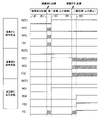
次に、図6は、通常制御状態から演算部A100が故障し、続いて演算部B200が故障したときの各信号の状態の一例を示すタイミングチャートである。t61に示す通常制御状態では、各信号はOFFである。 Next, FIG. 6 is a timing chart showing an example of the state of each signal when the arithmetic unit A100 fails in the normal control state and then the arithmetic unit B200 fails. In the normal control state shown at t61, each signal is OFF.
t62は、演算部A100が故障したタイミングである。t63は、演算部B200および演算部C300が演算部A100の異常を検出したタイミングであって、演算部B200およびC300のうちの少なくとも一方が演算部A100の機能代替を開始するタイミングである。 t62 is the timing at which the arithmetic unit A100 fails. t63 is the timing at which arithmetic units B200 and C300 detect an abnormality in arithmetic unit A100, and the timing at which at least one of arithmetic units B200 and C300 starts replacing the function of arithmetic unit A100.
t63ではW21およびW31がONとなり、以降、演算部A100は出力停止状態となるため、演算部B200は故障している演算部A100の影響を受けることなく、動作を継続できる。ここで、t62からt63の間は、演算部A100の出力信号である、W12,W13が不定状態となるが、ANDゲート13および14により、RST2,RST3はOFFを継続し、演算部B200および演算部C300は動作および出力を継続する。
At t63, W21 and W31 are turned ON, and thereafter the operation unit A100 stops outputting, so the operation unit B200 can continue its operation without being affected by the malfunctioning operation unit A100. Here, between t62 and t63, W12 and W13, which are the output signals of the arithmetic unit A100, are in an undefined state, but the AND
t62からt63の間は、FS1も不定となるため、ORゲート11により、システム全体から出力されるフェールセーフ信号FSは一時的に不定となる。ただし、フェールセーフ処理を実施する装置は、t62からt63の間、一時的にFSがON出力されたとしても、t63のタイミングで、フェールセーフ信号FSが解除された場合には、車両がフェールセーフ状態から復帰できるように構成される。
Since FS1 is also undefined between t62 and t63, the fail-safe signal FS output from the entire system by the
例えば、フェールセーフ処理を実施する装置として、電動自動車の電動モータのドライバが備えられる場合には、電動モータのドライバは、t62からt63の間、一時的に車両の駆動力をカットするだけで、t63のタイミングからは、通常制御状態と同じく、指令した駆動力で制御するように構成される。 For example, when an electric motor driver for an electric vehicle is provided as a device that performs fail-safe processing, the electric motor driver only cuts the driving force of the vehicle temporarily between t62 and t63. From timing t63, control is performed with the commanded driving force, as in the normal control state.
t64は、演算部B200が故障したタイミングであり、t65は、演算部C300が演算部B200の異常を検出し、フェールセーフ処理を行うタイミングである。t65でFS3がONとなり、フェールセーフ信号FSのON出力により、車両は安全に走行停止することができる。 t64 is the timing at which the calculation unit B200 fails, and t65 is the timing at which the calculation unit C300 detects an abnormality in the calculation unit B200 and performs fail-safe processing. At t65, FS3 is turned ON, and the vehicle can safely stop running due to the ON output of the fail-safe signal FS.
ここでt64以降は、演算部B200の出力信号である、W21が不定状態となるが、ラッチ回路15により、t64以降も演算部A100の出力停止状態が継続する。また、t64以降は、W23も不定状態となるが、ANDゲート14により、RST3はOFFを継続し、演算部C300は動作および出力を継続する。
After t64, W21, which is the output signal of the calculation unit B200, is in an undefined state, but the
さらに、t64以降は、FS2も不定状態となるため、ORゲート11により、システム全体から出力されるフェールセーフ信号FSは、t64からt65の間、不定となる。しかし、仮にこの間FS2がON出力されていたとしても、FSがONとなるタイミングがt65から早まるだけであり、車両は安全に走行停止することができるため、問題とはならない。
Further, after t64, FS2 is also in an undefined state, so the fail-safe signal FS output from the entire system by the
以上のような構成と動作により、3つの演算部の内任意の1つの演算部が故障した場合にも、残りの2つの演算部で制御と監視を継続可能である。また、残りの2つの演算部が故障部の動作と出力を停止させるので、単一故障に対し安全に走行機能を継続可能である。さらに、3つの内、任意の2つの演算部が故障した場合も、残りの1つの演算部がフェールセーフ信号を出力することで、二重故障に対し安全に走行停止可能である。 With the configuration and operation as described above, even if any one of the three calculation units fails, the remaining two calculation units can continue control and monitoring. In addition, since the remaining two calculation units stop the operation and output of the malfunctioning unit, the running function can be safely continued even in the event of a single malfunction. Furthermore, even if any two of the three calculation units fail, the remaining one calculation unit outputs a fail-safe signal so that the vehicle can be stopped safely against double failures.
[1-3.効果]
上記の車両制御システム1Aは、下記をポイントとする。
・3つの制御装置である演算部A100,B200,C300が相互に監視し合う構成とすることで、その内任意の1つの演算部が故障した場合にも、残りの2つの演算部で制御と監視を継続可能である。また、残りの2つの演算部が故障部の出力を停止させることで、単一故障に対し安全に走行機能を継続可能である。
[1-3. effect]
The above
・By configuring the three control units A100, B200, and C300 to mutually monitor each other, even if any one of them fails, the remaining two calculation units can still be used for control. Monitoring can be continued. In addition, the remaining two calculation units stop the output of the failure unit, so that the running function can be safely continued even in the event of a single failure.
・3つの内、任意の2つの演算部が故障した場合には、残りの1つの演算部がフェールセーフ信号を出力可能である。すなわち、二重故障に対し安全に走行停止可能である。
・各演算部に対し、他の演算部の代替が可能なソフトウェアをあらかじめ組み込んでおけば、待機系の演算処理装置を別途備える必要は無く、従来から存在する演算部のみで本案を実現でき、開発コストも抑えられる。
- If any two of the three calculation units fail, the remaining one calculation unit can output a fail-safe signal. In other words, it is possible to safely stop running against a double failure.
・If software that can replace other processing units is installed in advance for each processing unit, there is no need to separately provide a standby processing unit, and this proposal can be realized only with the conventional processing unit. It also reduces development costs.
詳細には、以上詳述した第1実施形態によれば、以下の構成を備えるとともに、以下の効果を奏する。
(1a)上記の車両制御システム1Aは、3つ以上の演算部A100,B200,C300を備える。演算部A100,B200,C300は、S210,S302,S402,S502で、当該演算部を除く他の演算部が故障していることを認識するように構成される。
Specifically, according to the first embodiment described in detail above, it has the following configuration and has the following effects.
(1a) The
故障した演算部A100,B200,C300を故障部とし、故障していない演算部A100,B200,C300を正常部として、演算部A100,B200,C300は、S214,S224,S234,S313,S323,S413,S423,S513,S523で、他の演算部のうちの予め2以上の数に設定された規定数以上の演算部A100,B200,C300が故障部である場合、予め設定されたフェールセーフ処理を実施する旨の出力を行い、他の演算部A100,B200,C300のうちの規定数未満の演算部A100,B200,C300が故障部である場合、正常部がフェールセーフ処理とは異なる車両の走行制御を実施する旨の出力を行うように構成される。 Calculation units A100, B200, and C300 that have failed are assumed to be faulty units, and calculation units A100, B200, and C300 that have not failed are assumed to be normal units. , S423, S513, and S523, if the operating units A100, B200, and C300, which are equal to or larger than the specified number set to 2 or more in advance among the other operating units, are faulty units, a preset fail-safe process is performed. Output to the effect that it will be implemented, and if less than the specified number of arithmetic units A100, B200, and C300 among the other arithmetic units A100, B200, and C300 are faulty units, the normal part is different from the fail-safe process. It is configured to output to the effect that the control is to be executed.
なお、本実施形態では、規定数は2に設定される。このため、演算部A100,B200,C300は、故障部の数が1である場合に、フェールセーフ処理とは異なる車両の走行制御として、通常制御を実施する旨の出力を行い、故障部の数が2である場合に、フェールセーフ処理を実施する旨の出力を行う。 Note that the specified number is set to two in the present embodiment. Therefore, when the number of faulty parts is 1, the arithmetic units A100, B200, and C300 output to the effect that normal control is to be performed as vehicle running control different from the fail-safe process, and the number of faulty parts is is 2, an output indicating that fail-safe processing is to be performed is performed.
このような構成によれば、可能な限り制御を継続できるようにしつつ、より安全に車両を制御することができる。
(1b)上記の車両制御システム1Aにおいて、各演算部A100,B200,C300は、他の演算部A100,B200,C300のうちの何れかが正常部である場合、S212,S222,S232で、故障部に対して出力を停止させるための停止指令を送信するように構成される。
According to such a configuration, the vehicle can be controlled more safely while the control can be continued as much as possible.
(1b) In the
このような構成によれば、車両の走行制御に悪影響を与える可能性がある故障部からの出力を遮断することができる。
(1c)上記の車両制御システム1Aは、各演算部A100,B200,C300から送信された停止指令を受信可能であり、2以上の演算部からの停止指令を受けたときのみ前記故障部の出力を停止させるように構成されたANDゲート12,13,14をさらに備える。
このような構成によれば、リセット入力側の演算部に対し、監視結果出力側の演算部の単一故障による影響を与えないようにし、故障している演算部のみを確実にリセットさせることができる。
(1d)上記の車両制御システム1Aは、停止指令が送信されると、少なくともフェールセーフ処理開始後まで前記故障部に対する該停止指令の出力を継続させるように構成されたラッチ回路15,16,17をさらに備える。
According to such a configuration, it is possible to cut off the output from the malfunctioning portion that may adversely affect the running control of the vehicle.
(1c) The
According to such a configuration, it is possible to prevent a single failure of the operation unit on the monitoring result output side from affecting the operation unit on the reset input side, and to reliably reset only the operation unit that is malfunctioning. can.
(1d) The
このような構成によれば、少なくともフェールセーフ処理開始後まで故障部からの出力を抑制することができる。
[2.第2実施形態]
[2-1.第1実施形態との相違点]
第2実施形態は、基本的な構成は第1実施形態と同様であるため、相違点について以下に説明する。なお、第1実施形態と同じ符号は、同一の構成を示すものであって、先行する説明を参照する。
According to such a configuration, it is possible to suppress the output from the failure part at least until after the start of the fail-safe process.
[2. Second Embodiment]
[2-1. Differences from First Embodiment]
Since the basic configuration of the second embodiment is the same as that of the first embodiment, differences will be described below. Note that the same reference numerals as in the first embodiment indicate the same configurations, and refer to the preceding description.
前述した第1実施形態では、複数の演算部A100,B200,C300が互いに故障しているか否かを監視するように構成した。監視の目的は、通常制御状態における任意の1つの演算部の故障検出と、1つの演算部故障中の残りの演算部での二重故障の検出であるので、これらが実現できるような監視体系であればよい。 In the first embodiment described above, it is configured to monitor whether or not the plurality of arithmetic units A100, B200, and C300 are mutually faulty. Since the purpose of monitoring is to detect a failure in any one computing unit under normal control and to detect double failures in the remaining computing units during the failure of one computing unit, a monitoring system capable of realizing these If it is
具体的には、第2実施形態では、各演算部A100,B200,C300が他の何れか1つ以上の演算部に監視されており、第一の故障発生後に、残りの2つで相互監視を行うように切り替えるような形態とする点で第1実施形態と相違する。これにより、通常制御状態における各演算部の監視に係る処理リソースを削減することができる。 Specifically, in the second embodiment, each of the arithmetic units A100, B200, and C300 is monitored by one or more other arithmetic units, and after the occurrence of the first failure, the remaining two mutually monitor each other. is different from the first embodiment in that it is switched to perform As a result, it is possible to reduce the processing resources for monitoring each calculation unit in the normal control state.
[2-2.構成]
図7は、第2実施形態の車両制御システム1Bを示す。図7の左図は、各演算部A100,B200,C300が通常制御状態である場合に、演算部A100が演算部B200に、演算部B200が演算部C300に、演算部C300が演算部A100に監視される構成を示す。つまり、上記の車両制御システム1Bにおいて各演算部A100,B200,C300は、ある演算部が監視対象とする1の演算部とは異なる1の演算部から監視される構成とすることで、監視対象となる演算部がリング状に接続され、全ての演算部A100,B200,C300が何れか1の演算部に監視されるように構成される。
[2-2. Constitution]
FIG. 7 shows a
また、図7の右図は、演算部A100故障時に、演算部B200と演算部C300が相互監視を行うように切り替えるケースを図示している。つまり、各演算部A100,B200,C300は、監視対象である演算部が故障部であることが認識された場合、正常部の何れかに対して、当該正常部の監視対象に、当該故障部が監視対象としていた演算部を追加するように構成される。 Further, the right diagram of FIG. 7 illustrates a case where, when the arithmetic unit A100 fails, the arithmetic units B200 and C300 are switched to monitor each other. In other words, when each of the arithmetic units A100, B200, and C300 recognizes that the arithmetic unit to be monitored is a faulty unit, each of the arithmetic units A100, B200, and C300 assigns the faulty unit is configured to add a computing unit that has been monitored.
[2-3.処理]
次に、第2実施形態の各演算部A100,B200,C300が、第1実施形態の監視処理に代えて実行する監視処理について、図8のフローチャートを用いて説明する。なお、本処理では説明を一部簡略化している。
[2-3. process]
Next, the monitoring process executed by each of the arithmetic units A100, B200, and C300 of the second embodiment in place of the monitoring process of the first embodiment will be described using the flowchart of FIG. Note that the description of this process is partially simplified.
第2実施形態の監視処理において、各演算部A100,B200,C300は、前述のS210で、監視対象の演算部が故障したか否かを判定する。ここでは、演算部A100が故障した場合の例について説明する。なお、演算部B200または演算部C300が故障した場合には、説明を省略するが、故障していない演算部が故障した演算部に応じて以下に述べる処理に対応する処理を実施すればよい。 In the monitoring process of the second embodiment, each of the computing units A100, B200, and C300 determines in S210 whether or not the computing unit to be monitored has failed. Here, an example in which the arithmetic unit A100 fails will be described. In addition, when the calculation unit B200 or the calculation unit C300 fails, although the explanation is omitted, the processing corresponding to the processing described below may be performed according to the malfunctioning calculation unit.
S210で演算部A100が故障したと判定された場合には、図8に示すS81で、演算部B200が演算部A100の異常を検出し、W21をON出力する。この際、演算部B200は、演算部C300に対し、演算部A100の異常を検出したことを通知する。 If it is determined in S210 that the arithmetic unit A100 has failed, in S81 shown in FIG. 8, the arithmetic unit B200 detects an abnormality in the arithmetic unit A100 and outputs W21. At this time, the calculation unit B200 notifies the calculation unit C300 that it has detected an abnormality in the calculation unit A100.
そして、演算部B200は演算部C300の監視を開始する。すなわち、演算部B200は演算部A100のみを監視していた状態から、演算部C300も監視する状態に遷移する。演算部C300は、既に演算部B200を監視しており、演算部B200が演算部C300の監視を開始することで、演算部B200および演算部C300は、互いに監視し合う、相互監視を開始する。 Then, the calculation unit B200 starts monitoring the calculation unit C300. That is, the computing unit B200 transitions from the state of monitoring only the computing unit A100 to the state of monitoring the computing unit C300 as well. The calculation unit C300 has already monitored the calculation unit B200, and when the calculation unit B200 starts monitoring the calculation unit C300, the calculation units B200 and C300 start monitoring each other.
続いて、演算部C300は、S82で、演算部B200から、演算部A100の異常検出通知を受信し、演算部B200が監視正常であることを確認した上で、W31をON出力する。演算部B200が監視正常であることを確認するのは、演算部B200が故障している場合には、演算部A100の異常検出通知自体が信頼性のない情報となるためである。演算部B200が監視正常であれば、演算部A100の異常検出通知は信頼性のある情報のため、演算部A100が故障していると正しく判断できる。 Subsequently, in S82, the calculation unit C300 receives from the calculation unit B200 the abnormality detection notification of the calculation unit A100, confirms that the monitoring of the calculation unit B200 is normal, and then outputs W31 to ON. The reason for confirming that the arithmetic unit B200 is monitoring normally is that if the arithmetic unit B200 is out of order, the abnormality detection notification of the arithmetic unit A100 itself becomes unreliable information. If the arithmetic unit B200 is monitoring normally, it can be correctly determined that the arithmetic unit A100 is out of order because the abnormality detection notification of the arithmetic unit A100 is reliable information.
S82以下は、S213以下の処理を実施するとよい。
[2-4.効果]
以上詳述した第2実施形態によれば、前述した第1実施形態の効果(1a)を奏し、さらに、以下の効果を奏する。
From S82 onwards, it is preferable to perform the processing from S213 onwards.
[2-4. effect]
According to the second embodiment described in detail above, the effect (1a) of the first embodiment described above is obtained, and the following effects are also obtained.
(2a)上記の車両制御システム1Bにおいて各演算部A100,B200,C300は、全ての演算部A100,B200,C300が何れか1以上の演算部に監視されるように構成され、当該演算部の監視対象である演算部が故障部であることが認識された場合、当該故障部が監視対象としていた演算部が当該故障部を除く他の何れの正常部からも監視されない場合には、1以上の正常部に対して、当該正常部の監視対象に、当該故障部が監視対象としていた演算部を追加するように構成される。
(2a) In the
このような構成によれば、演算部A100,B200,C300が1以上の演算部から監視される構成とし、何れかの演算部A100,B200,C300が故障したときに、必要に応じて一部の演算部の監視対象に他の演算部を追加する構成とするので、全ての演算部A100,B200,C300が常に2以上の演算部を監視する必要がない。よって、演算部A100,B200,C300間でのデータのやり取りを少なくすることができ、簡素な構成とすることができる。
なお、上記第2実施形態では、故障のない状態においては、演算部A100,B200,C300が1の演算部を順に監視することでリング状に監視する構成としたが、この構成に限らず、演算部A100,B200,C300が何れか1以上の演算部に監視されるように構成であればよい。例えば、演算部A100が演算部B200に、演算部B200が演算部C300に、演算部C300が演算部A100とB200とに監視される構成としてもよいし、演算部A100が演算部B200に、演算部B200およびC300が演算部A100に監視される構成としてもよい。
According to such a configuration, the computing units A100, B200, and C300 are configured to be monitored by one or more computing units, and when any of the computing units A100, B200, and C300 fails, some Since the configuration is such that other calculation units are added to the monitoring targets of the above calculation units, there is no need for all the calculation units A100, B200, and C300 to always monitor two or more calculation units. Therefore, it is possible to reduce the number of data exchanges among the arithmetic units A100, B200, and C300, and to simplify the configuration.
In the above-described second embodiment, when there is no failure, the arithmetic units A100, B200, and C300 are configured to monitor one arithmetic unit in order to perform ring-shaped monitoring. Any configuration may be employed as long as the arithmetic units A100, B200, and C300 are monitored by one or more arithmetic units. For example, a configuration may be adopted in which the computing unit A100 is monitored by the computing unit B200, the computing unit B200 is monitored by the computing unit C300, and the computing unit C300 is monitored by the computing units A100 and B200. The units B200 and C300 may be configured to be monitored by the arithmetic unit A100.
[3.第3実施形態]
[3-1.第1実施形態との相違点]
前述した第1実施形態では、複数の演算部が故障した場合に、フェールセーフ信号を出力するように構成した。これに対し、第3実施形態では、特定の演算部が故障した場合には、単一故障であってもフェールセーフ信号を出力する点で、第1実施形態と相違する。
[3. Third Embodiment]
[3-1. Differences from First Embodiment]
In the first embodiment described above, a fail-safe signal is output when a plurality of calculation units fails. On the other hand, the third embodiment is different from the first embodiment in that a fail-safe signal is output even if a single failure occurs in a specific arithmetic unit.
特定の演算部には、例えば、故障部が生じたことで車両の走行に支障を来す虞がある演算部、特に重要な演算部、本来であれば故障しにくいはずの演算部等が設定される。
ここでは、演算部C300が故障した場合に、他の演算部が故障していない場合であってもフェールセーフ信号を出力する例について説明する。
Specific calculation units include, for example, calculation units that may hinder the running of the vehicle due to failure, especially important calculation units, and calculation units that should not normally fail. be done.
Here, an example will be described in which the fail-safe signal is output when the arithmetic unit C300 fails even if the other arithmetic units do not malfunction.
[3-2.構成]
第3実施形態の車両制御システム1Cは、図9に示すように、第1実施形態の車両制御システム1Aに対して、ANDゲート14、ラッチ回路17、およびこれらの回路に関する信号ラインを省略した構成である。すなわち、車両制御システム1Cでは、演算部C300が異常な信号を出力していても、フェールセーフ信号が出力されて安全に走行停止できるため、演算部C300の動作および出力を停止する必要がなく、RST3は不要となる。
[3-2. Constitution]
As shown in FIG. 9, the
[3-3.処理]
次に、第3実施形態の各演算部A100,B200,C300が、第1実施形態の監視処理に代えて実行する監視処理について、図10のフローチャートを用いて説明する。
[3-3. process]
Next, monitoring processing executed by each of the arithmetic units A100, B200, and C300 of the third embodiment in place of the monitoring processing of the first embodiment will be described using the flowchart of FIG.
第3実施形態の監視処理において、各演算部A100,B200,C300は、前述のS210で、監視対象の演算部が故障したか否かを判定する。
S210で演算部C300が故障したと判定された場合には、図9に示すS91で、演算部A100または演算部B200あるいはその両方は、フェールセーフ信号FS1,FS2を出力する。これにより、S92に示すように、FSがONとなり、車両は安全に走行停止することができる。
In the monitoring process of the third embodiment, each of the arithmetic units A100, B200, and C300 determines whether or not the arithmetic unit to be monitored has failed in S210 described above.
If it is determined in S210 that the arithmetic unit C300 has failed, in S91 shown in FIG. 9, the arithmetic unit A100 and/or the arithmetic unit B200 output the fail-safe signals FS1 and FS2. As a result, as shown in S92, the FS is turned ON, and the vehicle can be stopped safely.
なお、S210の処理で、演算部C300以外の演算部が故障したと判定された場合には、第1実施形態の監視処理と同様とすればよいため記載を省略する。
[3-4.効果]
以上詳述した第3実施形態によれば、前述した第1実施形態の効果(1a)を奏し、さらに、以下の効果を奏する。
Note that if it is determined in the process of S210 that a calculation unit other than the calculation unit C300 has failed, the monitoring process may be performed in the same manner as in the first embodiment, so description thereof will be omitted.
[3-4. effect]
According to the third embodiment described in detail above, the effect (1a) of the first embodiment described above is obtained, and the following effects are also obtained.
(3a)上記の車両制御システム1Cにおいて演算部A100,B200,C300は、故障部が生じたことで車両の走行に支障を来すか否かを判定し、車両の走行に支障を来すと判定されると、他の演算部A100,B200,C300のうちの何れかが正常部である場合であっても、フェールセーフ処理を実施する旨の出力を行うように構成される。
(3a) In the above-described
このような構成によれば、車両の走行に支障を来す虞がある演算部A100,B200,C300が故障部になった場合には、フェールセーフ処理を実施できるので、より安全に車両を制御することができる。 According to such a configuration, if the arithmetic units A100, B200, and C300, which may hinder the running of the vehicle, become a failure unit, fail-safe processing can be performed, so that the vehicle can be controlled more safely. can do.
(3b)上記の車両制御システム1Cにおいては、演算部C300をリセットする構成を省略している。このような構成によれば、RST3の信号ラインを設けるコストを削減できる。
(3b) In the
(3c)上記の車両制御システム1Cは、予め設定された特定演算部A100,B200,C300が故障部であるか否かを判定し、特定演算部が故障部であると判定されると、他の演算部のうちの規定数未満の演算部が故障部である場合であっても、フェールセーフ処理を実施する旨の出力を行うように構成される。
(3c) The
このような構成によれば、重要な演算部や故障しにくいはずの演算部等の特定演算部が故障部になった場合には、複数の正常部が存在するとしてもフェールセーフ処理を実施できるので、より安全に車両を制御することができる。 According to such a configuration, when a specific calculation unit such as an important calculation unit or a calculation unit that should be unlikely to fail becomes a failure unit, fail-safe processing can be performed even if there are a plurality of normal units. Therefore, the vehicle can be controlled more safely.
(3d)なお、上記の車両制御システム1Cの採否は、RST3信号ラインを設けることによる費用対効果から判断すればよい。例えば、演算部C300には単純な監視のみを行わせるなど、複雑な機能を持たせなくてよい場合、演算部C300はCPUやメモリを持たない、比較的小規模で単純なICで実現されてもよい。
(3d) Whether or not the
単純なICで実現されるが故に、演算部C300の単一故障率が、演算部A100と演算部B200の二重故障が起こる確率よりも極めて低い場合、すなわち、高い確率で、演算部C300の単一故障よりも先に演算部A100と演算部B200の二重故障が起こる場合には、RST3信号ラインを設けることによる費用対効果が低いのであるから、本実施形態の構成を採用してもよい。 Since it is realized by a simple IC, if the single failure rate of the operation part C300 is much lower than the probability of double failures of the operation part A100 and the operation part B200, that is, with a high probability, the operation part C300 If the double failure of the arithmetic unit A100 and the arithmetic unit B200 occurs before the single failure, the provision of the RST3 signal line is less cost-effective. good.
また、走行を継続するのに必ず必要な演算部がある場合、該演算部の故障時には走行を継続できないのであるから、本実施形態の構成を採用し、該演算部の単一故障を検出した他の演算部からフェールセーフ信号を出力するようにすればよい。 In addition, when there is a calculation unit that is absolutely necessary for continuation of running, the vehicle cannot continue running when the calculation unit fails. A fail-safe signal may be output from another computing unit.
[4.第4実施形態]
[4-1.第1実施形態との相違点]
前述した第1実施形態の車両制御システム1Aは、3つの演算部を備えて構成している。これに対し、第4実施形態の車両制御システム1Dでは、4つ以上の演算部を備えて構成している点で、第1実施形態と相違する。
[4. Fourth Embodiment]
[4-1. Differences from First Embodiment]
The
すなわち、4つ以上の演算部のうち、任意の1つの演算部が故障した場合にも、残りの演算部で制御と監視を継続可能であればよい。また、任意の2つの演算部が故障した場合には、残っている1つ以上の演算部がフェールセーフ信号を出力可能であればよい。 In other words, even when any one of the four or more computing units fails, it is sufficient that the remaining computing units can continue control and monitoring. Also, if two arbitrary calculation units fail, at least one remaining calculation unit should be capable of outputting a fail-safe signal.
[4-2.構成]
図11は4つの演算部によるシステム構成例である。車両制御システム1Dは、演算部D400、ANDゲート18、およびラッチ回路19をさらに備える。演算部D400は、例えば、他の演算部と同様のハードウェア構成を有し、予め設定された任意の車両制御を実行する。
[4-2. Constitution]
FIG. 11 is an example of a system configuration with four calculation units. The
車両制御システム1Dでは、1つの演算部は隣接する2つの演算部と相互に監視を行う。ただし、隣接していない、図11では対角の位置にある演算部は、相互に監視する必要はない。
In the
ANDゲート18は、演算部A100および演算部C300から出力されるW14,W34に基づく出力を行う。ラッチ回路19は、ANDゲート18の出力が入力され、他のラッチ回路15~17と同様に作動する。
The AND
[4-3.処理]
次に、第4実施形態の各演算部A100,B200,C300,D400が、第1実施形態の監視処理に代えて実行する監視処理について、図12のフローチャートを用いて説明する。図12は、第一の故障として、例えば、演算部A100が故障したときのフロー詳細である。
[4-3. process]
Next, the monitoring processing executed by the computing units A100, B200, C300, and D400 of the fourth embodiment in place of the monitoring processing of the first embodiment will be described using the flowchart of FIG. FIG. 12 shows the details of the flow when, for example, the arithmetic unit A100 fails as the first failure.
第4実施形態の監視処理において、各演算部A100,B200,C300,D400は、前述のS210で、監視対象の演算部が故障したか否かを判定する。S210で演算部A100が故障したと判定された場合には、図12に示すS121で、演算部B200または演算部D400が演算部A100の異常を検出し、W21およびW41をON出力する。 In the monitoring process of the fourth embodiment, each of the computing units A100, B200, C300, and D400 determines in S210 whether or not the monitored computing unit has failed. When it is determined in S210 that the arithmetic unit A100 has failed, in S121 shown in FIG. 12, the arithmetic unit B200 or the arithmetic unit D400 detects an abnormality in the arithmetic unit A100 and outputs W21 and W41.
これにより、S122に示すように、RST1がONとなり、演算部A100は動作および出力が停止する。そして、S123で、演算部B200または演算部D400は、演算部C300に対し、演算部A100の異常を検出したことを通知する。 As a result, as shown in S122, RST1 is turned ON, and operation and output of the arithmetic unit A100 are stopped. Then, in S123, computing unit B200 or computing unit D400 notifies computing unit C300 that it has detected an abnormality in computing unit A100.
続いて、S124で、演算部C300は、演算部B200または演算部D400から、演算部A100の異常検出通知を受信し、演算部B200または演算部D400が監視正常であることを確認した上で、演算部A100の異常をメモリに記憶する。演算部B200または演算部D400が監視正常であることを確認するのは、演算部B200または演算部D400が故障している場合には、演算部B200または演算部D400からの演算部A100の異常検出通知自体が信頼性のない情報となるためである。演算部B200または演算部D400が監視正常であれば、演算部A100の異常検出通知は信頼性のある情報のため、演算部A100が故障していると正しく判断できる。 Subsequently, in S124, the calculation unit C300 receives the abnormality detection notification of the calculation unit A100 from the calculation unit B200 or the calculation unit D400, confirms that the monitoring of the calculation unit B200 or the calculation unit D400 is normal, The abnormality of the arithmetic unit A100 is stored in the memory. The reason for confirming that the arithmetic unit B200 or the arithmetic unit D400 is normal is that if the arithmetic unit B200 or the arithmetic unit D400 fails, the arithmetic unit B200 or the arithmetic unit D400 detects an abnormality in the arithmetic unit A100. This is because the notification itself becomes unreliable information. If the arithmetic unit B200 or the arithmetic unit D400 is normally monitored, the abnormality detection notification of the arithmetic unit A100 is reliable information, so that it can be correctly determined that the arithmetic unit A100 is out of order.
そして、S125で、演算部B200,C300,D400は、通常制御状態における制御を継続しつつ、何れか1つ以上の演算部で演算部A100の車両制御機能代替を開始する。すると、演算部B200と演算部C300とが相互に監視を継続し、演算部D400と演算部C300とが相互に監視を継続している状態で、走行を継続できる。 Then, in S125, the calculation units B200, C300, and D400 continue the control in the normal control state, and at least one of the calculation units starts substituting the vehicle control function of the calculation unit A100. Then, the calculation unit B200 and the calculation unit C300 continue to monitor each other, and the vehicle can continue running in a state where the calculation unit D400 and the calculation unit C300 continue to monitor each other.
引き続き、演算部A100が故障しているときの処理を図13のフローチャートで説明する。演算部A100の故障中には、S1301で、演算部B200,C300,D400は、演算部A100の故障中での走行制御を継続し、S1302で、さらに他の演算部の故障が発生したか否かを判定する。すなわち、第一の故障である演算部A100の故障中に、他の演算部の故障である第二の故障が発生したか否かを判定する。 Subsequently, the processing when the arithmetic unit A100 is out of order will be described with reference to the flowchart of FIG. During the failure of the arithmetic unit A100, in S1301, the arithmetic units B200, C300, and D400 continue running control during the failure of the arithmetic unit A100. determine whether That is, it is determined whether or not a second failure, which is a failure of another arithmetic unit, has occurred during the failure of the arithmetic unit A100, which is the first failure.
演算部C300が演算部B200の故障の発生を認識した場合、演算部C300は、S1312以下の処理を実施する。また、演算部B200または演算部D400が演算部C300の故障の発生を認識した場合、演算部B200または演算部D400は、S1322以下の処理を実施する。また、演算部C300が演算部D400の故障の発生を認識した場合、演算部C300は、S1332以下の処理を実施する。 When the calculation unit C300 recognizes that the calculation unit B200 has failed, the calculation unit C300 performs the processing from S1312 onwards. Further, when the calculation unit B200 or the calculation unit D400 recognizes that the calculation unit C300 has failed, the calculation unit B200 or the calculation unit D400 performs the processing from S1322 onwards. Further, when the calculation unit C300 recognizes that the calculation unit D400 has failed, the calculation unit C300 performs the processing from S1332 onwards.
S1312では、演算部C300が演算部B200の異常を検出し、演算部C300は演算部A100と演算部B200の二重故障を認識する。
続いて、S1313で、演算部C300はフェールセーフ処理として、FS3をON出力する。これにより、S1314に示すように、FSがONとなり、車両は安全に走行停止することができる。すなわち、演算部C300は、S124で記憶していた演算部A100の異常と合わせて、他の演算部の異常を認識したときに、二重故障であると認識できるので、良好にフェールセーフ処理を行うことができる。
In S1312, the calculation unit C300 detects an abnormality in the calculation unit B200, and recognizes the double failure of the calculation units A100 and B200.
Subsequently, in S1313, the calculation unit C300 turns on FS3 as fail-safe processing. As a result, as shown in S1314, FS is turned ON, and the vehicle can be stopped safely. That is, when the arithmetic unit C300 recognizes the malfunction of the other arithmetic units together with the malfunction of the arithmetic unit A100 stored in S124, it can recognize that there is a double failure, so that the fail-safe process can be performed satisfactorily. It can be carried out.
一方、S1322では、演算部B200または演算部D400が演算部C300の異常を検出し、演算部B200または演算部D400は演算部A100と演算部C300の二重故障を認識する。続いて、S1323で、演算部B200または演算部D400はフェールセーフ処理として、FS2をON出力する。これにより、S1324に示すように、FSがONとなり、車両は安全に走行停止することができる。 On the other hand, in S1322, calculation unit B200 or calculation unit D400 detects an abnormality in calculation unit C300, and calculation unit B200 or calculation unit D400 recognizes a double failure of calculation units A100 and C300. Subsequently, in S1323, the calculation unit B200 or the calculation unit D400 turns on FS2 as fail-safe processing. As a result, as shown in S1324, FS is turned ON, and the vehicle can be stopped safely.
また、S1332では、演算部C300が演算部D400の異常を検出し、演算部C300は演算部A100と演算部D400の二重故障を認識する。
続いて、S1333で、演算部C300はフェールセーフ処理として、FS3をON出力する。これにより、S1334に示すように、FSがONとなり、車両は安全に走行停止することができる。
Also, in S1332, the arithmetic unit C300 detects an abnormality in the arithmetic unit D400, and the arithmetic unit C300 recognizes the double failure of the arithmetic units A100 and D400.
Subsequently, in S1333, the calculation unit C300 turns on FS3 as fail-safe processing. As a result, as shown in S1334, FS is turned ON, and the vehicle can be stopped safely.
なお、S210の処理で、演算部C300以外の演算部が故障したと判定された場合には、故障した演算部以外の演算部が故障した演算部に応じてS121以下に対応する処理を実行すればよいため記載を省略する。 In the process of S210, when it is determined that a calculation unit other than the calculation unit C300 has failed, the processing corresponding to S121 and subsequent steps may be executed according to the failed calculation unit other than the failed calculation unit. Description is omitted because it is sufficient.
[4-4.効果]
以上詳述した第4実施形態によれば、前述した第1実施形態の効果(1a)を奏し、さらに、以下の効果を奏する。
[4-4. effect]
According to the fourth embodiment described in detail above, the effect (1a) of the first embodiment described above is obtained, and the following effects are also obtained.
(4a)第4実施形態の車両制御システム1Dでは、4つ以上の演算部を備えて構成される。このような構成によれば、演算部の数が4以上の構成であっても二重故障に対応することができる。
(4a) The
[5.他の実施形態]
以上、本開示の実施形態について説明したが、本開示は上述の実施形態に限定されることなく、種々変形して実施することができる。
[5. Other embodiments]
Although the embodiments of the present disclosure have been described above, the present disclosure is not limited to the above-described embodiments, and various modifications can be made.
(5a)上記実施形態では、原則として2つの演算部が故障した場合にフェールセーフ処理を実施したが、これに限定されるものではない。例えば、多数の演算部を備える構成では、例えば3つ以上の演算部が故障した場合にフェールセーフ処理を実施するようにしてもよい。すなわち、演算部A100,B200,C300,D400は、故障した演算部A100,B200,C300,D400を故障部とし、故障していない演算部A100,B200,C300,D400を正常部として、他の演算部のうちの予め3以上の数に設定された規定数以上の演算部が故障部である場合、予め設定されたフェールセーフ処理を実施する旨の出力を行い、他の演算部のうちの規定数未満の演算部A100,B200,C300,D400が故障部である場合、正常部がフェールセーフ処理とは異なる車両の走行制御を実施する旨の出力を行うように構成されてもよい。 (5a) In the above embodiment, in principle, fail-safe processing is performed when two computing units fail, but the present invention is not limited to this. For example, in a configuration including a large number of arithmetic units, fail-safe processing may be performed when, for example, three or more arithmetic units fail. That is, the calculation units A100, B200, C300, and D400 are configured such that the faulty calculation units A100, B200, C300, and D400 are the faulty units, and the non-faulty calculation units A100, B200, C300, and D400 are the normal units. If more than a specified number of operation units preset to 3 or more among the units is a failure unit, an output indicating that a preset fail-safe process is to be performed is performed, and the specified number of the other operation units is output. If less than the number of calculation units A100, B200, C300, and D400 are failure units, the normal units may be configured to output an output indicating that the vehicle running control different from the fail-safe process is to be performed.
(5b)上記実施形態における1つの構成要素が有する複数の機能を、複数の構成要素によって実現したり、1つの構成要素が有する1つの機能を、複数の構成要素によって実現したりしてもよい。また、複数の構成要素が有する複数の機能を、1つの構成要素によって実現したり、複数の構成要素によって実現される1つの機能を、1つの構成要素によって実現したりしてもよい。また、上記実施形態の構成の一部を省略してもよい。また、上記実施形態の構成の少なくとも一部を、他の上記実施形態の構成に対して付加又は置換してもよい。なお、特許請求の範囲に記載した文言から特定される技術思想に含まれるあらゆる態様が本開示の実施形態である。 (5b) A plurality of functions possessed by one component in the above embodiment may be realized by a plurality of components, or a function possessed by one component may be realized by a plurality of components. . Also, a plurality of functions possessed by a plurality of components may be realized by a single component, or a function realized by a plurality of components may be realized by a single component. Also, part of the configuration of the above embodiment may be omitted. Moreover, at least part of the configuration of the above embodiment may be added or replaced with respect to the configuration of the other above embodiment. It should be noted that all aspects included in the technical idea specified by the wording described in the claims are embodiments of the present disclosure.
(5c)上述した車両制御システム1A,1B,1C,1Dの他、当該車両制御システム1A,1B,1C,1Dの構成要素となる演算部A100,B200,C300,D400、演算部A100,B200,C300を備える車両制御装置、当該車両制御システム1Aとしてコンピュータを機能させるためのプログラム、このプログラムを記録した半導体メモリ等の非遷移的実態的記録媒体、監視方法など、種々の形態で本開示を実現することもできる。
(5c) In addition to the
[6.実施形態の構成と本開示の構成との対応関係]
上記実施形態において、車両制御システム1A,1B,1C,1Dは本開示でいう車両制御装置に相当し、ANDゲート12,13,14,18は本開示でいう停止出力部に相当し、ラッチ回路15,16,17,19は本開示でいう出力継続部に相当する。また、演算部A100,B200,C300,D400が実行する処理のうちの、S210,S302,S402,S502,S1302の処理は本開示でいう故障認識部に相当し、S214,S224,S234,S313,S323,S413,S423,S513,S523,S91,S125,S1313,S1323,S1333の処理は制御出力部に相当する。
[6. Correspondence between the configuration of the embodiment and the configuration of the present disclosure]
In the above embodiments, the
また、S212,S222,S232,S81,S82,S121の処理は本開示でいう停止送信部に相当し、S81の処理は本開示でいう追加設定部に相当し、S210の処理は本開示でいう支障判定部、故障判定部に相当する。 Further, the processing of S212, S222, S232, S81, S82, and S121 corresponds to the stop transmission unit referred to in this disclosure, the processing of S81 corresponds to the additional setting unit referred to in this disclosure, and the processing of S210 corresponds to It corresponds to a trouble determination unit and a failure determination unit.
1A,1B,1C,1D…車両制御システム、11…ORゲート、12,13,14,18…ANDゲート、15,16,17,19…ラッチ回路、A100,B200,C300,D400…演算部。 1A, 1B, 1C, 1D... Vehicle control system, 11... OR gate, 12, 13, 14, 18... AND gate, 15, 16, 17, 19... Latch circuit, A100, B200, C300, D400... Operation part.
Claims (6)
各演算部は、
当該演算部を除く他の演算部が故障していることを認識するように構成された故障認識部(S210,S302,S402,S502,S1302)と、
故障した演算部を故障部とし、故障していない演算部を正常部として、前記他の演算部のうちの予め2以上の数に設定された規定数以上の演算部が前記故障部である場合、予め設定されたフェールセーフ処理を実施する旨の出力を行い、前記他の演算部のうちの前記規定数未満の演算部が前記故障部である場合、前記正常部が前記フェールセーフ処理とは異なる車両の走行制御を実施する旨の出力を行うように構成された制御出力部(S214,S224,S234,S313,S323,S413,S423,S513,S523,S91,S125,S1313,S1323,S1333)と、
前記各演算部から送信された停止指令を受信可能であり、2以上の演算部からの停止指令を受けたときのみ前記故障部の出力を停止させるように構成された停止出力部(12,13,14,18)と、
を備え、
前記制御出力部は、前記フェールセーフ処理とは異なる車両の走行制御として、前記故障部に対して出力を停止させるための停止指令を送信するように構成された停止送信部(S212,S222,S232,S81,S82,S121)、
をさらに備え、
前記停止出力部は、前記各演算部からの停止指令を入力とし、論理積を出力するように構成されたANDゲートを備える
車両制御システム。 A vehicle control system (1A, 1B, 1C, 1D),
Each calculation part is
a fault recognizing unit (S210, S302, S402, S502, S1302) configured to recognize that other calculating units other than the relevant calculating unit are out of order;
A case where a malfunctioning arithmetic unit is defined as a malfunctioning unit, a normal arithmetic unit is defined as a non-faulty arithmetic unit, and the malfunctioning unit is a predetermined number or more of the other arithmetic units that is set to a number equal to or greater than 2 in advance. , an output indicating that a preset fail-safe process is to be performed, and if the number of operation units less than the specified number among the other operation units is the failure unit, the normal unit is the fail-safe process A control output section (S214, S224, S234, S313, S323, S413, S423, S513, S523, S91, S125, S1313, S1323, S1333) configured to perform an output indicating that running control of different vehicles is to be performed When,
A stop output unit (12, 13) capable of receiving a stop command transmitted from each of the calculation units and configured to stop the output of the malfunctioning unit only when receiving a stop command from two or more calculation units , 14, 18) and
with
The control output unit is a stop transmission unit (S212, S222, S232 , S81, S82, S121),
further comprising
The stop output unit includes an AND gate configured to receive a stop command from each of the calculation units and output a logical product.
vehicle control system.
前記停止指令が送信されると、少なくともフェールセーフ処理開始後まで前記故障部に
対する該停止指令の出力を継続させるように構成された出力継続部(15,16,17,19)、
をさらに備える車両制御システム。 A vehicle control system according to claim 1 ,
an output continuation unit (15, 16, 17, 19) configured to continue outputting the stop command to the faulty unit until at least after the start of the fail-safe process when the stop command is transmitted;
A vehicle control system further comprising:
前記各演算部は、
全ての演算部が何れか1以上の演算部に監視されるように構成され、
前記故障認識部により当該演算部の監視対象である演算部が故障部であることが認識された場合、1以上の正常部に対して、当該正常部の監視対象に、当該故障部が監視対象としていた演算部を追加するように構成された追加設定部(S81)、
をさらに備える車両制御システム。 A vehicle control system according to claim 1 or claim 2 ,
Each computing unit
All computing units are configured to be monitored by any one or more computing units,
When the failure recognizing unit recognizes that the operation unit to be monitored by the operation unit is a failure unit, one or more normal units are to be monitored by the normal unit, and the failure unit is to be monitored. An additional setting unit (S81) configured to add a calculation unit that was set as
A vehicle control system further comprising:
故障部が生じたことで車両の走行に支障を来すか否かを判定する支障判定部(S210)、
をさらに備え、
前記制御出力部は、車両の走行に支障を来すと判定されると、前記他の演算部のうちの前記規定数未満の演算部が前記故障部である場合であっても、前記フェールセーフ処理を実施する旨の出力を行う
ように構成された車両制御システム。 A vehicle control system according to any one of claims 1 to 3 ,
a trouble determination unit (S210) that determines whether or not the occurrence of a faulty part will hinder the running of the vehicle;
further comprising
When it is determined that the running of the vehicle will be hindered, the control output unit performs the fail-safe operation even if the number of operation units less than the specified number among the other operation units is the failure unit. A vehicle control system configured to output an indication that processing is to be performed.
複数の前記 演算部のうちの予め設定された演算部を表す特定演算部が前記故障部であるか否かを判定する故障判定部(S210)、
をさらに備え、
前記制御出力部は、前記特定演算部が前記故障部であると判定されると、前記他の演算部のうちの前記規定数未満の演算部が前記故障部である場合であっても、前記フェールセーフ処理を実施する旨の出力を行う
ように構成された車両制御システム。 Claim 1 to claim41. The vehicle control system according to any one of
a plurality of said a failure determination unit (S210) that determines whether or not a specific operation unit representing a preset operation unit among the operation units is the failure unit;
further comprising
When it is determined that the specific arithmetic unit is the faulty unit, the control output unit controls the above Output to the effect that fail-safe processing will be performed
A vehicle control system configured to:
各演算部は、
当該演算部を除く他の演算部が故障していることを認識するように構成された故障認識部(S210,S302)と、
故障した演算部を故障部とし、故障していない演算部を正常部として、前記他の演算部のうちの予め2以上の数に設定された規定数以上の演算部が前記故障部である場合、予め設定されたフェールセーフ処理を実施する旨の出力を行い、前記他の演算部のうちの前記規定数未満の演算部が前記故障部である場合、前記正常部が前記フェールセーフ処理とは異なる車両の走行制御を実施する旨の出力を行うように構成された制御出力部(S214,S224,S234,S313,S323,S413,S423,S513,S523,S91,S125,S1313,S1323,S1333)と、
前記各演算部から送信された停止指令を受信可能であり、2以上の演算部からの停止指令を受けたときのみ前記故障部の出力を停止させるように構成された停止出力部(12,13,14,18)と、
を備え、
前記制御出力部は、前記フェールセーフ処理とは異なる車両の走行制御として、前記故障部に対して出力を停止させるための停止指令を送信するように構成された停止送信部(S212,S222,S232,S81,S82,S121)、
をさらに備え、
前記停止出力部は、前記各演算部からの停止指令を入力とし、論理積を出力するように構成されたANDゲートを備える
車両制御装置。 A vehicle control device (1A, 1B, 1C, 1D),
Each calculation part is
a fault recognizing unit (S210, S302) configured to recognize that other calculating units other than the relevant calculating unit are out of order;
A case where a malfunctioning arithmetic unit is defined as a malfunctioning unit, a normal arithmetic unit is defined as a non-faulty arithmetic unit, and the malfunctioning unit is a predetermined number or more of the other arithmetic units that is set to a number equal to or greater than 2 in advance. , an output indicating that a preset fail-safe process is to be performed, and if the number of operation units less than the specified number among the other operation units is the failure unit, the normal unit is the fail-safe process A control output section (S214, S224, S234, S313, S323, S413, S423, S513, S523, S91, S125, S1313, S1323, S1333) configured to perform an output indicating that running control of different vehicles is to be performed When,
A stop output unit (12, 13) capable of receiving a stop command transmitted from each of the calculation units and configured to stop the output of the malfunctioning unit only when receiving a stop command from two or more calculation units , 14, 18) and
with
The control output unit is a stop transmission unit (S212, S222, S232 , S81, S82, S121),
further comprising
The stop output unit includes an AND gate configured to receive a stop command from each of the calculation units and output a logical product.
Vehicle controller.
Priority Applications (2)
| Application Number | Priority Date | Filing Date | Title |
|---|---|---|---|
| JP2017253897A JP7163576B2 (en) | 2017-12-28 | 2017-12-28 | Vehicle control system and vehicle control device |
| DE102018221840.4A DE102018221840A1 (en) | 2017-12-28 | 2018-12-14 | Vehicle control system and vehicle control device |
Applications Claiming Priority (1)
| Application Number | Priority Date | Filing Date | Title |
|---|---|---|---|
| JP2017253897A JP7163576B2 (en) | 2017-12-28 | 2017-12-28 | Vehicle control system and vehicle control device |
Publications (2)
| Publication Number | Publication Date |
|---|---|
| JP2019121043A JP2019121043A (en) | 2019-07-22 |
| JP7163576B2 true JP7163576B2 (en) | 2022-11-01 |
Family
ID=66817108
Family Applications (1)
| Application Number | Title | Priority Date | Filing Date |
|---|---|---|---|
| JP2017253897A Active JP7163576B2 (en) | 2017-12-28 | 2017-12-28 | Vehicle control system and vehicle control device |
Country Status (2)
| Country | Link |
|---|---|
| JP (1) | JP7163576B2 (en) |
| DE (1) | DE102018221840A1 (en) |
Families Citing this family (3)
| Publication number | Priority date | Publication date | Assignee | Title |
|---|---|---|---|---|
| JP7338418B2 (en) * | 2019-11-15 | 2023-09-05 | 株式会社デンソー | Inverter shutdown device |
| US20230202494A1 (en) * | 2020-06-16 | 2023-06-29 | Hitachi Astemo, Ltd. | Electronic control device and vehicle control method |
| JP7637973B2 (en) | 2021-03-11 | 2025-03-03 | 株式会社Zmp | Autonomous Vehicles |
Citations (5)
| Publication number | Priority date | Publication date | Assignee | Title |
|---|---|---|---|---|
| JP2011039702A (en) | 2009-08-07 | 2011-02-24 | Autonetworks Technologies Ltd | Control system |
| JP2011065528A (en) | 2009-09-18 | 2011-03-31 | Toyota Motor Corp | Multiprocessor system |
| JP2015058865A (en) | 2013-09-20 | 2015-03-30 | Ntn株式会社 | Control apparatus for rear-wheel steering apparatus |
| JP2016071771A (en) | 2014-10-01 | 2016-05-09 | 株式会社デンソー | Control device and monitoring device |
| JP2017094908A (en) | 2015-11-24 | 2017-06-01 | 株式会社デンソー | Electronic control device |
Family Cites Families (1)
| Publication number | Priority date | Publication date | Assignee | Title |
|---|---|---|---|---|
| JPH0887341A (en) * | 1994-09-16 | 1996-04-02 | Fujitsu Ltd | Computer system with automatic degenerate startup function |
-
2017
- 2017-12-28 JP JP2017253897A patent/JP7163576B2/en active Active
-
2018
- 2018-12-14 DE DE102018221840.4A patent/DE102018221840A1/en active Pending
Patent Citations (5)
| Publication number | Priority date | Publication date | Assignee | Title |
|---|---|---|---|---|
| JP2011039702A (en) | 2009-08-07 | 2011-02-24 | Autonetworks Technologies Ltd | Control system |
| JP2011065528A (en) | 2009-09-18 | 2011-03-31 | Toyota Motor Corp | Multiprocessor system |
| JP2015058865A (en) | 2013-09-20 | 2015-03-30 | Ntn株式会社 | Control apparatus for rear-wheel steering apparatus |
| JP2016071771A (en) | 2014-10-01 | 2016-05-09 | 株式会社デンソー | Control device and monitoring device |
| JP2017094908A (en) | 2015-11-24 | 2017-06-01 | 株式会社デンソー | Electronic control device |
Also Published As
| Publication number | Publication date |
|---|---|
| JP2019121043A (en) | 2019-07-22 |
| DE102018221840A1 (en) | 2019-07-04 |
Similar Documents
| Publication | Publication Date | Title |
|---|---|---|
| US9563523B2 (en) | Architecture for scalable fault tolerance in integrated fail-silent and fail-operational systems | |
| CN112004730B (en) | vehicle control device | |
| US8935569B2 (en) | Control computer system, method for controlling a control computer system, and use of a control computer system | |
| US9372774B2 (en) | Redundant computing architecture | |
| US20160103450A1 (en) | Fail-Safe EE Architecture for Automated Driving | |
| CN110678375B (en) | Vehicle control device and vehicle control system | |
| US7047440B1 (en) | Dual/triple redundant computer system | |
| US8493703B2 (en) | Integrated circuit arrangement for safety critical regulation systems | |
| US10037016B2 (en) | Hybrid dual-duplex fail-operational pattern and generalization to arbitrary number of failures | |
| CN110785742A (en) | Device and method for actuating a vehicle module as a function of a status signal | |
| JP7163576B2 (en) | Vehicle control system and vehicle control device | |
| EP3626554A1 (en) | Vehicle control system | |
| US10503166B2 (en) | Method of processing data for an automated vehicle | |
| US20110043323A1 (en) | Fault monitoring circuit, semiconductor integrated circuit, and faulty part locating method | |
| KR101723932B1 (en) | An method for diagnosing a failure of flight control computer having dual channel | |
| CN105253076A (en) | Failure management in a vehicle | |
| US20240270263A1 (en) | Control device and assistance system for a vehicle | |
| CN113015666A (en) | Control architecture for a vehicle | |
| JP5766360B2 (en) | In-vehicle communication system and in-vehicle communication method | |
| Hammett et al. | Achieving 10⁻ ⁹ Dependability with Drive-by-Wire Systems | |
| CN117980886A (en) | System for providing an output signal based on a generated environmental model of an environment of a mobile platform | |
| KR101448013B1 (en) | Fault-tolerant apparatus and method in multi-computer for Unmanned Aerial Vehicle | |
| CN107783530B (en) | Failure operable system design mode based on software code migration | |
| CN106970550B (en) | Vehicle subsystem communication arbitration | |
| JP2020052479A (en) | Vehicle controller and vehicle control method |
Legal Events
| Date | Code | Title | Description |
|---|---|---|---|
| A621 | Written request for application examination |
Free format text: JAPANESE INTERMEDIATE CODE: A621 Effective date: 20201117 |
|
| A977 | Report on retrieval |
Free format text: JAPANESE INTERMEDIATE CODE: A971007 Effective date: 20210908 |
|
| A131 | Notification of reasons for refusal |
Free format text: JAPANESE INTERMEDIATE CODE: A131 Effective date: 20210928 |
|
| A521 | Request for written amendment filed |
Free format text: JAPANESE INTERMEDIATE CODE: A523 Effective date: 20211108 |
|
| A131 | Notification of reasons for refusal |
Free format text: JAPANESE INTERMEDIATE CODE: A131 Effective date: 20220322 |
|
| A521 | Request for written amendment filed |
Free format text: JAPANESE INTERMEDIATE CODE: A523 Effective date: 20220512 |
|
| TRDD | Decision of grant or rejection written | ||
| A01 | Written decision to grant a patent or to grant a registration (utility model) |
Free format text: JAPANESE INTERMEDIATE CODE: A01 Effective date: 20220920 |
|
| A61 | First payment of annual fees (during grant procedure) |
Free format text: JAPANESE INTERMEDIATE CODE: A61 Effective date: 20221003 |
|
| R151 | Written notification of patent or utility model registration |
Ref document number: 7163576 Country of ref document: JP Free format text: JAPANESE INTERMEDIATE CODE: R151 |