JP7161851B2 - Method for confirming state of immunoassay device and immunoassay device - Google Patents
Method for confirming state of immunoassay device and immunoassay device Download PDFInfo
- Publication number
- JP7161851B2 JP7161851B2 JP2018034674A JP2018034674A JP7161851B2 JP 7161851 B2 JP7161851 B2 JP 7161851B2 JP 2018034674 A JP2018034674 A JP 2018034674A JP 2018034674 A JP2018034674 A JP 2018034674A JP 7161851 B2 JP7161851 B2 JP 7161851B2
- Authority
- JP
- Japan
- Prior art keywords
- container
- liquid phase
- labeling substance
- immunoassay device
- substance
- Prior art date
- Legal status (The legal status is an assumption and is not a legal conclusion. Google has not performed a legal analysis and makes no representation as to the accuracy of the status listed.)
- Active
Links
Images


Classifications
-
- G—PHYSICS
- G01—MEASURING; TESTING
- G01N—INVESTIGATING OR ANALYSING MATERIALS BY DETERMINING THEIR CHEMICAL OR PHYSICAL PROPERTIES
- G01N33/00—Investigating or analysing materials by specific methods not covered by groups G01N1/00 - G01N31/00
- G01N33/48—Biological material, e.g. blood, urine; Haemocytometers
- G01N33/50—Chemical analysis of biological material, e.g. blood, urine; Testing involving biospecific ligand binding methods; Immunological testing
- G01N33/53—Immunoassay; Biospecific binding assay; Materials therefor
- G01N33/543—Immunoassay; Biospecific binding assay; Materials therefor with an insoluble carrier for immobilising immunochemicals
- G01N33/551—Immunoassay; Biospecific binding assay; Materials therefor with an insoluble carrier for immobilising immunochemicals the carrier being inorganic
- G01N33/553—Metal or metal coated
-
- G—PHYSICS
- G01—MEASURING; TESTING
- G01N—INVESTIGATING OR ANALYSING MATERIALS BY DETERMINING THEIR CHEMICAL OR PHYSICAL PROPERTIES
- G01N35/00—Automatic analysis not limited to methods or materials provided for in any single one of groups G01N1/00 - G01N33/00; Handling materials therefor
-
- G—PHYSICS
- G01—MEASURING; TESTING
- G01N—INVESTIGATING OR ANALYSING MATERIALS BY DETERMINING THEIR CHEMICAL OR PHYSICAL PROPERTIES
- G01N35/00—Automatic analysis not limited to methods or materials provided for in any single one of groups G01N1/00 - G01N33/00; Handling materials therefor
- G01N35/02—Automatic analysis not limited to methods or materials provided for in any single one of groups G01N1/00 - G01N33/00; Handling materials therefor using a plurality of sample containers moved by a conveyor system past one or more treatment or analysis stations
Landscapes
- Health & Medical Sciences (AREA)
- Immunology (AREA)
- Life Sciences & Earth Sciences (AREA)
- Chemical & Material Sciences (AREA)
- Engineering & Computer Science (AREA)
- Physics & Mathematics (AREA)
- Analytical Chemistry (AREA)
- Pathology (AREA)
- General Physics & Mathematics (AREA)
- Hematology (AREA)
- Biomedical Technology (AREA)
- Molecular Biology (AREA)
- Urology & Nephrology (AREA)
- General Health & Medical Sciences (AREA)
- Biochemistry (AREA)
- Microbiology (AREA)
- Medicinal Chemistry (AREA)
- Food Science & Technology (AREA)
- Cell Biology (AREA)
- Biotechnology (AREA)
- Inorganic Chemistry (AREA)
- Automatic Analysis And Handling Materials Therefor (AREA)
Description
この発明は、検体中の被検物質の測定を行う免疫測定装置に関する。 The present invention relates to an immunoassay device for measuring a test substance in a sample.
免疫測定を高感度化するための技術として、免疫複合体転移法を用いる免疫測定装置がある(たとえば、特許文献1参照)。 As a technique for increasing the sensitivity of immunoassay, there is an immunoassay device using an immune complex transfer method (see, for example, Patent Document 1).
上記特許文献1に開示された免疫測定装置は、図23に示すように、第1容器901内で、被検物質911および標識物質912を含む免疫複合体913を固相担体914上に形成させ、遊離試薬915によって免疫複合体913を固相担体914から遊離させる。そして、免疫測定装置は、第1容器901内の固相担体914を残して、遊離した免疫複合体913を含む液相を第2容器902に移し替える免疫複合体転移法を実行した後、第2容器902中の免疫複合体913に含まれる標識物質912に基づく信号を検出する。
As shown in FIG. 23, the immunoassay apparatus disclosed in
ところで、免疫測定装置により得られる測定結果は疾病の診断や治療方針の決定の判断材料となるため、測定結果の信頼性が求められる。測定結果の信頼性を確保する方法として、従来では、既知濃度の被検物質を含む精度管理試料を測定する方法があり、簡便に実施できるため、免疫複合体転移法を利用しない従来型の免疫測定装置で利用されている。 By the way, since the measurement results obtained by the immunoassay device are used as a basis for determining disease diagnosis and treatment policy, the reliability of the measurement results is required. As a method to ensure the reliability of measurement results, there is a conventional method of measuring a quality control sample containing a known concentration of the test substance. Used in measuring equipment.
しかしながら、免疫複合体転移法を用いる免疫測定装置では、免疫複合体転移法を実行するために、従来の免疫測定装置にはない機能が付加されている。このことから、従来の精度管理試料を測定する方法では、免疫複合体転移法を実行するための機能の正常、異常などの状態確認を実施できないおそれがある。免疫複合体転移法を用いる上記特許文献1においても、免疫複合体転移法を実行するための機能の状態確認を行う手法については開示されておらず、免疫複合体転移法を実行するための機能の状態確認を簡便に行えるようにすることが望まれる。
However, in an immunoassay device using the immune complex transfer method, a function not found in conventional immunoassay devices is added in order to execute the immune complex transfer method. For this reason, the conventional method of measuring quality control samples may not be able to confirm the state of normality, abnormality, etc. of the function for performing the immunocomplex transfer method. Even in
この発明は、免疫測定装置における免疫複合体転移法を実行するための機能の状態確認を簡便に行えるようにすることに向けたものである。 The present invention is directed to making it possible to easily check the state of the function for executing the immune complex transfer method in an immunoassay device.
この発明の第1の局面による免疫測定装置の状態確認方法は、検体中の被検物質(81)と標識物質(83)とを含み固相担体(82)に担持された免疫複合体(84)を収容する第1容器(11)内で、免疫複合体(84)を固相担体(82)から遊離させ、第1容器(11)内の液相を第2容器(12)に移す複合体転移処理を行う免疫測定装置(100)の状態確認方法であって、少なくとも標識物質(21)が結合した固相担体(82)を含む管理試料(20)が収容された第1容器(11)内の固相担体(82)を第1容器(11)内で集める処理を行う工程と、第1容器(11)内の液相を第2容器(12)に移す工程と、液相が移された第2容器(12)内の標識物質(21)を検出する工程と、第2容器(12)内の標識物質(21)の検出値と基準値との比較に基づいて、複合体転移処理を行う免疫測定装置(100)における第1容器(11)内の固相担体(82)を集める機能の異常の有無または異常の程度を判定する工程と、を備える。
この発明の第2の局面による免疫測定装置の状態確認方法は、検体中の被検物質(81)と標識物質(83)とを含み固相担体(82)に担持された免疫複合体(84)を収容する第1容器(11)内で、免疫複合体(84)を固相担体(82)から遊離させ、第1容器(11)内の液相を第2容器(12)に移す複合体転移処理を行う免疫測定装置(100)の状態確認方法であって、少なくとも標識物質(21)を液相として含む管理試料(20)が収容された第1容器(11)内の液相を第2容器(12)に移す工程と、液相が移された第2容器(12)内の標識物質(21)を検出する工程と、第2容器(12)内の標識物質(21)の検出値と基準値との比較に基づいて、複合体転移処理を行う免疫測定装置(100)における第1容器(11)内の液相を第2容器(12)に移し替える機能の異常の有無または異常の程度を判定する工程と、を備える。
A method for confirming the state of an immunoassay device according to the first aspect of the present invention provides an immune complex (84) containing a test substance (81) in a specimen and a labeling substance (83) and supported on a solid phase carrier (82). ) in a first container (11) containing an immunoconjugate (84) released from a solid phase carrier (82) and transferring the liquid phase in the first container (11) to a second container (12). A method for confirming the state of an immunoassay device (100) for body metastasis processing, comprising: a first container (11 ) in a first container (11), transferring the liquid phase in the first container (11) to a second container (12), and Based on the step of detecting the labeling substance (21) in the transferred second container (12) and comparing the detected value of the labeling substance (21) in the second container (12) with the reference value, the complex and determining the presence or absence or degree of abnormality in the function of collecting the solid phase carriers (82) in the first container (11) in the immunoassay device (100) for performing metastasis treatment.
A method for confirming the state of an immunoassay device according to the second aspect of the present invention provides an immune complex (84) containing a test substance (81) in a sample and a labeling substance (83) and supported on a solid phase carrier (82). ) in a first container (11) containing an immunoconjugate (84) released from a solid phase carrier (82) and transferring the liquid phase in the first container (11) to a second container (12). A method for confirming the state of an immunoassay device (100) that performs body metastasis processing, comprising: a step of transferring to a second container (12); a step of detecting the labeling substance (21) in the second container (12) to which the liquid phase has been transferred; Presence or absence of abnormality in the function of transferring the liquid phase in the first container (11) to the second container (12) in the immunoassay device (100) that performs the complex transfer treatment based on the comparison between the detected value and the reference value. or determining the degree of abnormality .
第1および第2の局面による免疫測定装置の状態確認方法では、上記のように構成することによって、標識物質(21)を含む管理試料(20)を収容する第1容器(11)に対して、複合体転移処理と同様の液相の移し替え動作を行って、第2容器(12)に移された管理試料(20)中の標識物質(21)を検出できる。複合体転移処理が正常に行われなければ、予想される検出結果から外れた異常な検出結果が取得されることになる。これにより、第2容器(12)中の標識物質(21)の検出結果に基づいて、複合体転移処理が正常に実施できたかどうかなどの免疫測定装置の状態を判定することができる。その結果、免疫測定装置における免疫複合体転移法を実行するための機能の状態確認を簡便に行うことができる。ここで、複合体転移処理においては、免疫複合体(84)を含む液相を第2容器(12)に移して、第1容器(11)には固相担体(82)を残すために、第1容器(11)内の固相担体(82)を集める機能が正常か否か、が重要となる。また、複合体転移処理によって第2容器(12)に移し替えた免疫複合体(84)を検出するために、第1容器(11)内の液相を第2容器(12)に移し替える機能が正常か否か、が重要となる。第1および第2の局面によれば、これらの機能の異常の有無を判定できるので、測定結果の信頼性を確保するために特に有用である。 In the method for confirming the state of an immunoassay device according to the first and second aspects, the first container (11) containing the control sample (20) containing the labeling substance (21) is , a liquid phase transfer operation similar to the complex transfer treatment can be performed to detect the labeling substance (21) in the control sample (20) transferred to the second container (12). If the complex transfer process is not performed normally, an abnormal detection result deviating from the expected detection result will be obtained. This makes it possible to determine the state of the immunoassay device, such as whether or not the complex transfer treatment was performed normally, based on the detection result of the labeling substance (21) in the second container (12). As a result, it is possible to easily check the state of the function for executing the immune complex transfer method in the immunoassay device. Here, in the complex transfer treatment, in order to transfer the liquid phase containing the immune complex (84) to the second container (12) and leave the solid phase carrier (82) in the first container (11), It is important whether the function of collecting the solid support (82) in the first container (11) is normal. A function of transferring the liquid phase in the first container (11) to the second container (12) in order to detect the immune complex (84) transferred to the second container (12) by the complex transfer treatment. is normal or not. According to the first and second aspects, the presence or absence of abnormality in these functions can be determined, which is particularly useful for ensuring the reliability of measurement results.
上記第1の局面による免疫測定装置の状態確認方法において、好ましくは、固相担体(82)を集める機能の状態を判定する工程において、第2容器(12)内における標識物質(21)の検出値が基準値(V1)を超えること、に基づいて第1容器(11)内の固相担体(82)を集める機能の異常を判定する。
上記第2の局面による免疫測定装置の状態確認方法において、好ましくは、第1容器(11)内の液相を第2容器(12)に移し替える機能の状態を判定する工程において、第2容器(12)内における標識物質(21)の検出値が基準値を下回ること、に基づいて第1容器(11)内の液相を第2容器(12)に移し替える機能の異常を判定する。
このように構成すれば、正常状態での測定によって得られる検出値に基づいて、正常と異常とを区別するための基準値(V1、V2)を予め設定しておくことにより、検出値と基準値(V1、V2)とを比べるだけで、複合体転移処理の異常判定を容易に行うことができる。
In the method for confirming the state of the immunoassay device according to the first aspect, preferably, in the step of determining the state of the function of collecting the solid phase carrier (82), the labeling substance (21) is detected in the second container (12). Abnormalities in the function of collecting the solid phase carriers (82) in the first container (11) are determined based on the fact that the value exceeds the reference value (V1).
In the method for confirming the state of an immunoassay device according to the second aspect, preferably, in the step of determining the state of the function of transferring the liquid phase in the first container (11) to the second container (12), the second container Abnormality in the function of transferring the liquid phase in the first container (11) to the second container (12) is judged based on the fact that the detected value of the labeling substance (21) in (12) is below the reference value.
With this configuration, by presetting the reference values (V1, V2) for distinguishing between normality and abnormality based on the detection value obtained by measurement in the normal state, the detection value and the reference value can be obtained. Only by comparing the values (V1, V2), it is possible to easily determine whether the complex transfer processing is abnormal.
上記第1または第2の局面による免疫測定装置の状態確認方法において、好ましくは、第1容器(11)内の液相を第2容器(12)に移す工程の前に、免疫測定装置(100)により、管理試料(20)を第1容器(11)に分注する工程をさらに備える。このように構成すれば、免疫測定装置(100)のユーザや装置の保守サービスを行うサービススタッフが事前に管理試料(20)を第1容器(11)に準備しておかなくても、免疫測定装置(100)によって容易に、管理試料(20)を第1容器(11)に収容させることができる。 In the method for confirming the state of an immunoassay device according to the first or second aspect, preferably, before the step of transferring the liquid phase in the first container (11) to the second container (12), the immunoassay device (100 ) to dispense the control sample (20) into the first container (11). With this configuration, even if the user of the immunoassay device (100) or the service staff who performs the maintenance service of the device does not prepare the control sample (20) in the first container (11) in advance, the immunoassay can be performed. The control sample (20) can be easily accommodated in the first container (11) by the device (100).
上記第1の局面による免疫測定装置の状態確認方法において、好ましくは、固相担体(22)が磁性粒子であり、固相担体(22)を集める処理は、磁性粒子を磁力源(52)により集磁する処理を含み、固相担体(82)を集める機能の状態を判定する工程は、第2容器(12)内の標識物質(21)の検出値と基準値との比較に基づいて、磁力源(52)による集磁機能の異常を判定する工程を含む。なお、本明細書において、「集磁機能」とは、磁性粒子を集める機能であり、集磁機能が正常であるとは、集磁しきれずに第1容器(11)から第2容器(12)へ液相と共に移される磁性粒子の持越量が許容範囲内に抑えられることを指す。このように構成すれば、標識物質(21)が結合した磁性粒子を集磁するため、第2容器(12)内の標識物質(21)の検出値に基づいて、磁力源(52)による集磁機能が正常であるか異常であるかを容易に判定できる。 In the method for confirming the state of an immunoassay device according to the first aspect , the solid phase carriers (22) are preferably magnetic particles, and the process of collecting the solid phase carriers (22) is preferably performed by moving the magnetic particles by the magnetic force source (52). The step of determining the state of the function of collecting the solid phase carrier (82) , including the process of collecting magnetism, is based on comparison between the detected value of the labeling substance (21) in the second container (12) and the reference value , It includes a step of judging an abnormality in the magnetic collecting function of the magnetic force source (52). In this specification, the term "magnetism collection function" means the function of collecting magnetic particles, and a normal magnetism collection function means that the magnetism cannot be fully collected and ) is kept within an acceptable range. With this configuration, the magnetic particles to which the labeling substance (21) is bound are magnetically collected. It can be easily determined whether the magnetic function is normal or abnormal.
磁力源(52)による集磁機能の異常を判定する場合、好ましくは、標識物質(21)の検出値が基準値(V1)を上回る場合に、磁力源(52)による集磁機能の異常があると判定する。このように構成すれば、標識物質(21)の検出値が基準値(V1)を上回る場合には、液相を第2容器(12)に移す際に磁性粒子を十分に集磁できていない可能性が高いため、検出値と基準値(V1)との対比により、磁力源(52)による集磁機能を容易に判定できる。 When determining an abnormality in the magnetic collection function of the magnetic force source (52), preferably, when the detected value of the labeling substance (21) exceeds the reference value (V1), the magnetic force source (52) detects an abnormality in the magnetic collection function. Determine that there is. With this configuration, when the detected value of the labeling substance (21) exceeds the reference value (V1), the magnetic particles are not sufficiently collected when the liquid phase is transferred to the second container (12). Since the possibility is high, the magnetic collecting function of the magnetic force source (52) can be easily determined by comparing the detected value and the reference value (V1).
この場合、好ましくは、基準値(V1)は、集磁されずに第2容器(12)に移される磁性粒子の許容上限量に相当する標識物質(21)の予想検出値である。このように構成すれば、許容上限量を超える量の磁性粒子が第2容器(12)に移されている場合に、磁力源(52)による集磁機能が異常であることを容易に判定できる。そのため、許容上限量を超えないことが確認されることにより、測定結果の信頼性を確保することができる。 In this case, preferably, the reference value (V1) is an expected detection value of the labeling substance (21) corresponding to the allowable upper limit amount of the magnetic particles transferred to the second container (12) without magnetization. With this configuration, when the amount of magnetic particles exceeding the allowable upper limit amount is transferred to the second container (12), it can be easily determined that the magnetic force collection function of the magnetic force source (52) is abnormal. . Therefore, by confirming that the allowable upper limit amount is not exceeded, the reliability of the measurement result can be ensured.
上記固相担体を集める処理を行う構成において、好ましくは、第1容器(11)内の液相を第2容器(12)に移す工程の前に、第1容器(11)内で、既知濃度の被検物質(81)を含む試料、被検物質(81)と結合する標識物質(83)、被検物質(81)と結合する捕捉物質(86)、および捕捉物質(86)と結合する固相担体(82)とを接触させることにより、第1容器(11)内に管理試料(20)を調製する工程をさらに備える。このように構成すれば、被検物質(81)を含む検体を実際に測定する場合と同様の処理工程によって、標識物質(83)が結合した固相担体(82)を第1容器(11)中に形成することができる。 In the configuration for performing the process of collecting the solid phase carriers, preferably, before the step of transferring the liquid phase in the first container (11) to the second container (12), in the first container (11), a sample containing a test substance (81) of, a labeling substance (83) that binds to the test substance (81), a capture substance (86) that binds to the test substance (81), and a capture substance (86) that binds to Further comprising the step of preparing a control sample (20) in the first container (11) by contacting it with a solid phase support (82). With this configuration, the solid phase carrier (82) bound with the labeling substance (83) is transferred to the first container (11) by the same processing steps as in the actual measurement of the sample containing the test substance (81). can be formed in
この場合、好ましくは、管理試料(20)は、検体の測定時において複合体転移処理前に第1容器(11)に分注される第1固相担体(82a)を含む。このように構成すれば、被検物質(81)を含む検体を実際に測定する場合に分注される第1固相担体(82a)を用いて、標識物質(21)が結合した固相担体(22)を第1容器(11)中に形成することができる。すなわち、免疫測定装置(100)の状態確認のために専用の固相担体(22)を別途用意する必要がないので、免疫測定装置(100)の利便性を向上させることができる。 In this case, preferably, the control sample (20) contains the first solid phase carrier (82a) dispensed into the first container (11) prior to the complex transfer treatment during sample measurement. With this configuration, the first solid phase carrier (82a) dispensed when actually measuring the specimen containing the test substance (81) is used to bind the labeling substance (21) to the solid phase carrier. (22) can be formed in the first container (11). That is, since it is not necessary to separately prepare a dedicated solid phase carrier (22) for checking the state of the immunoassay device (100), the convenience of the immunoassay device (100) can be improved.
上記被検物質(81)を含む試料、標識物質(83)、捕捉物質(86)、および固相担体(82)を接触させる工程を備える場合、好ましくは、管理試料(20)は、検体の測定時において複合体転移処理後に第2容器(12)に分注される第2固相担体(82b)を含む。このように構成すれば、被検物質(81)を含む検体を実際に測定する場合に分注される第2固相担体(82b)を用いて、標識物質(21)が結合した固相担体(22)を第1容器(11)中に形成することができる。すなわち、免疫測定装置(100)の状態確認のために専用の固相担体(22)を別途用意する必要がないので、免疫測定装置(100)の利便性を向上させることができる。 When the step of contacting the sample containing the test substance (81), the labeling substance (83), the capture substance (86), and the solid phase carrier (82) is provided, preferably the control sample (20) is It includes a second solid phase carrier (82b) that is dispensed into the second container (12) after complex transfer treatment at the time of measurement. With this configuration, the solid phase carrier to which the labeling substance (21) is bound is obtained using the second solid phase carrier (82b) that is dispensed when actually measuring the sample containing the test substance (81). (22) can be formed in the first container (11). That is, since it is not necessary to separately prepare a dedicated solid phase carrier (22) for checking the state of the immunoassay device (100), the convenience of the immunoassay device (100) can be improved.
上記被検物質(81)を含む試料、標識物質(83)、捕捉物質(86)、および固相担体(82)を接触させる工程を備える場合、好ましくは、第1容器(11)内の液相を第2容器(12)に移す工程の前に、被検物質(81)、標識物質(83)、捕捉物質(86)を含む免疫複合体(84)と結合した固相担体(82)と、液相とを分離するBF分離を行う工程をさらに備える。このように構成すれば、BF分離によって、固相担体(82)と結合しなかった液相中の標識物質(83)を、第1容器(11)から排除できる。そのため、第1容器(11)内の液相を第2容器(12)に移す工程において、液相中に標識物質(83)が混ざることを抑制できるので、免疫測定装置(100)の状態確認のための標識物質(83)の検出精度を向上させることができる。 When the step of contacting the sample containing the test substance (81), the labeling substance (83), the capture substance (86), and the solid phase carrier (82) is preferably performed, the liquid in the first container (11) A solid phase carrier (82) bound with an immune complex (84) containing a test substance (81), a labeling substance (83) and a capture substance (86) before the step of transferring the phase to the second container (12). and a step of performing BF separation for separating the liquid phase. With this configuration, the labeling substance (83) in the liquid phase that has not bound to the solid phase carrier (82) can be removed from the first container (11) by BF separation. Therefore, in the step of transferring the liquid phase in the first container (11) to the second container (12), it is possible to suppress the labeling substance (83) from being mixed in the liquid phase. The detection accuracy of the labeling substance (83) for the can be improved.
この場合、好ましくは、複合体転移処理において、第1容器(11)に遊離試薬(85)が分注されることにより、免疫複合体(84)が固相担体(82)から遊離され、BF分離を行う工程の後、第1容器(11)内の液相を第2容器(12)に移す工程の前に、遊離試薬(85)を含まない液相を第1容器(11)に分注する工程をさらに備える。このように構成すれば、被検物質(81)を含む検体を実際に測定する場合に分注される遊離試薬(85)に代えて、遊離試薬(85)を含まない液相(25)を分注するので、実際の検体測定時に遊離試薬(85)を分注するのと同様の動作で、免疫測定装置(100)の状態確認を行える。そして、その場合でも、標識物質(83)と固相担体(82)との結合が解消されることがないので、固相担体(82)を集める機能の確認を適切に行える。 In this case, preferably, in the complex transfer treatment, the immune complex (84) is released from the solid phase carrier (82) by dispensing the free reagent (85) into the first container (11), and the BF After the step of separating, the liquid phase free of free reagents (85) is divided into the first container (11) before the step of transferring the liquid phase in the first container (11) to the second container (12). The step of pouring is further provided. With this configuration, the liquid phase (25) not containing the free reagent (85) is used instead of the free reagent (85) dispensed when actually measuring the specimen containing the test substance (81). Since the sample is dispensed, the status of the immunoassay device (100) can be confirmed by the same operation as dispensing the free reagent (85) during actual sample measurement. Even in that case, the binding between the labeling substance (83) and the solid phase carrier (82) is not eliminated, so the function of collecting the solid phase carrier (82) can be properly confirmed.
上記第1の局面による免疫測定装置の状態確認方法において、好ましくは、管理試料(20)は、被検物質(81)と結合せずに標識物質(21)と結合した第3固相担体(23)を含む。このように構成すれば、免疫測定装置(100)の状態確認のために専用の試薬として、被検物質(81)を含まない第3固相担体(23)を用いて、固相担体(22)を集める機能の確認を行うことができる。固相担体(22)が標識物質(21)だけでなく被検物質(81)とも結合する場合、被検物質(81)の種類に応じて結合可能な固相担体(22)および標識物質(21)を複数種類用意するのに対して、被検物質(81)を含まない第3固相担体(23)では、被検物質(81)の種類によらずに免疫測定装置(100)の状態確認を行うことができる。そのため、免疫測定装置(100)の状態確認をより簡便に行うことができる。 In the method for confirming the state of an immunoassay device according to the first aspect , preferably, the control sample (20) is a third solid-phase carrier ( 23). With this configuration, the solid phase carrier (22) is used as a dedicated reagent for confirming the state of the immunoassay device (100), using the third solid phase carrier (23) that does not contain the test substance (81). ) can be checked. When the solid phase carrier (22) binds not only the labeling substance (21) but also the test substance (81), the binding solid phase carrier (22) and the labeling substance ( 21) are prepared in a plurality of types, whereas the third solid-phase carrier (23) containing no test substance (81) is used for the immunoassay device (100) regardless of the type of the test substance (81). You can check the status. Therefore, the status of the immunoassay device (100) can be checked more easily.
上記第2の局面による免疫測定装置の状態確認方法において、好ましくは、第1容器(11)内の液相を第2容器(12)に移す工程は、第1容器(11)内の液相を吸引し、吸引した液相を第2容器(12)に吐出する分注処理を含み、第1容器(11)内の液相を第2容器(12)に移し替える機能の状態を判定する工程は、第2容器(12)内の標識物質(21)の検出値と基準値との比較に基づいて、分注機能の異常を判定する工程を含む。なお、本明細書において、「分注機能」とは、第1容器(11)内の液相を吸引する機能および吸引した液相を第2容器(12)に吐出する機能を含み、分注機能が正常であるとは、第1容器(11)から液相を吸引して、吸引した液相を第2容器(12)へ吐出できることを指す。このように構成すれば、標識物質(21)の検出値に基づいて、液相の吸引および液相の吐出を行う分注機能が正常であるか異常であるかを容易に判定できる。 In the method for confirming the state of an immunoassay device according to the second aspect , preferably, the step of transferring the liquid phase in the first container (11) to the second container (12) includes: and discharging the sucked liquid phase into the second container ( 12), and determine the state of the function of transferring the liquid phase in the first container (11) to the second container (12) The process includes a process of judging an abnormality in the pipetting function based on a comparison between the detected value of the labeling substance (21) in the second container (12) and the reference value . As used herein, the term "dispensing function" includes the function of aspirating the liquid phase in the first container (11) and the function of discharging the aspirated liquid phase into the second container (12). Normal function means that the liquid phase can be sucked from the first container (11) and the sucked liquid phase can be discharged to the second container (12). With this configuration, it is possible to easily determine whether the pipetting function of sucking the liquid phase and discharging the liquid phase is normal or abnormal based on the detected value of the labeling substance (21).
上記分注機能の異常を判定する場合、好ましくは、標識物質(21)の検出値が基準値(V2)を下回る場合に、分注機能の異常があると判定する。このように構成すれば、標識物質(21)の検出値が基準値(V2)を下回る場合には、第1容器(11)から第2容器(12)に、標識物質(21)を含む液相を適切に移せていない可能性が高いため、検出値と基準値(V2)との対比により、分注機能を容易に判定できる。 When judging an abnormality in the pipetting function, it is preferably judged that there is an abnormality in the pipetting function when the detected value of the labeling substance (21) is lower than the reference value (V2). With this configuration, when the detected value of the labeling substance (21) is below the reference value (V2), the liquid containing the labeling substance (21) is transferred from the first container (11) to the second container (12). Since there is a high possibility that the phase has not been properly transferred, the dispensing function can be easily determined by comparing the detected value with the reference value (V2).
この場合、好ましくは、基準値(V2)は、管理試料(20)に含まれる標識物質(21)の予想検出値の許容限度として設定された値である。このように構成すれば、標識物質(21)を含む液相を第2容器(12)に移す工程を実行しても検出値が基準値(V2)を下回る場合に、分注機能が異常であることを容易に判定できる。そのため、検出値が基準値(V2)を上回ることが確認されることにより、測定結果の信頼性を確保することができる。 In this case, preferably, the reference value (V2) is a value set as the allowable limit of the expected detection value of the labeling substance (21) contained in the controlled sample (20). With this configuration, if the detection value is below the reference value (V2) even after the step of transferring the liquid phase containing the labeling substance (21) to the second container (12) is performed, the dispensing function is abnormal. can be easily determined. Therefore, by confirming that the detected value exceeds the reference value (V2), the reliability of the measurement result can be ensured.
上記第2の局面による免疫測定装置の状態確認方法において、好ましくは、管理試料(20)は、検体の測定時において第1容器(11)に分注される標識物質(83)を含む。このように構成すれば、被検物質(81)を含む検体を実際に測定する場合に分注される標識物質(83)を用いて、第1容器(11)内の液相を第2容器(12)に移す機能が正常か否かを確認できる。すなわち、免疫測定装置(100)の状態確認のために専用の標識物質(21)を別途用意する必要がないので、免疫測定装置(100)の利便性を向上させることができる。 In the method for confirming the state of an immunoassay device according to the second aspect , the control sample (20) preferably contains a labeling substance (83) dispensed into the first container (11) during sample measurement. With this configuration, the liquid phase in the first container (11) is transferred to the second container using the labeling substance (83) dispensed when actually measuring the specimen containing the test substance (81). It can be confirmed whether the function transferred to (12) is normal. That is, since it is not necessary to separately prepare a dedicated labeling substance (21) for confirming the state of the immunoassay device (100), the convenience of the immunoassay device (100) can be improved.
上記第1または第2の局面による免疫測定装置の状態確認方法において、管理試料(20)に含まれる標識物質(21)が酵素であり、第2容器(12)内の標識物質(21)を検出する工程は、酵素の基質を第2容器(12)に添加し、酵素反応により生じた反応産物から生じる信号を測定することにより行われてもよい。 In the immunoassay device state confirmation method according to the first or second aspect, the labeling substance (21) contained in the control sample (20) is an enzyme, and the labeling substance (21) in the second container (12) is The detecting step may be performed by adding a substrate for the enzyme to the second container (12) and measuring the signal generated from the reaction product produced by the enzymatic reaction.
この発明の第3の局面による免疫測定装置(100)は、検体中の被検物質(81)と標識物質(83)とを含み固相担体(82)に担持された免疫複合体(84)を収容する第1容器(11)内で、免疫複合体(84)を固相担体(82)から遊離させ、第1容器(11)内の液相を第2容器(12)に移す複合体転移処理を行う免疫測定装置(100)であって、少なくとも標識物質(21)が結合した固相担体(82)を含む管理試料(20)が収容された第1容器(11)内の固相担体(82)を第1容器(11)内で集める処理を行うとともに、第1容器(11)内の液相を第2容器(12)に移す処理を行う機構部(50)と、液相が移された第2容器(12)内の標識物質(21)を検出する検出部(60)と、検出部(60)の検出値と基準値との比較に基づいて、複合体転移処理における第1容器(11)内の固相担体(82)を集める機能の異常を判定する判定部(70)と、を備える。
この発明の第4の局面による免疫測定装置(100)は、検体中の被検物質(81)と標識物質(83)とを含み固相担体(82)に担持された免疫複合体(84)を収容する第1容器(11)内で、免疫複合体(84)を固相担体(82)から遊離させ、第1容器(11)内の液相を第2容器(12)に移す複合体転移処理を行う免疫測定装置(100)であって、少なくとも標識物質(21)を液相として含む管理試料(20)が収容された第1容器(11)内の液相を第2容器(12)に移す処理を行う機構部(50)と、液相が移された第2容器(12)内の標識物質(21)を検出する検出部(60)と、検出部(60)の検出値と基準値との比較に基づいて、複合体転移処理における第1容器(11)内の液相を第2容器(12)に移し替える機能の異常を判定する判定部(70)と、を備える。
An immunoassay device (100) according to the third aspect of the present invention is an immune complex (84) containing a test substance (81) in a sample and a labeling substance (83) and supported on a solid phase carrier (82). releasing the immunoconjugate (84) from the solid phase carrier (82) in the first container (11) containing the complex An immunoassay device (100) for performing transfer treatment, wherein a solid phase in a first container (11) containing a control sample (20) containing a solid phase carrier (82) to which at least a labeling substance (21) is bound a mechanism part (50) for collecting the carrier (82) in the first container (11) and transferring the liquid phase in the first container (11) to the second container (12); Based on the comparison between the detection unit (60) that detects the labeling substance (21) in the second container (12) to which the is transferred and the detection value of the detection unit (60) and the reference value, in the complex transfer treatment and a judgment unit (70) for judging abnormality of the function of collecting the solid phase carriers (82) in the first container (11) .
An immunoassay device (100) according to the fourth aspect of the present invention is an immune complex (84) containing a test substance (81) in a sample and a labeling substance (83) and supported on a solid phase carrier (82). releasing the immunoconjugate (84) from the solid phase carrier (82) in the first container (11) containing the complex An immunoassay device (100) for performing transfer treatment, wherein a liquid phase in a first container (11) containing a control sample (20) containing at least a labeling substance (21) as a liquid phase is transferred to a second container (12). ), a detection unit (60) for detecting the labeling substance (21) in the second container (12) to which the liquid phase has been transferred, and the detection value of the detection unit (60) and a determination unit (70) for determining an abnormality in the function of transferring the liquid phase in the first container (11) to the second container (12) in the complex transfer treatment based on the comparison between the .
第3および第4の局面による免疫測定装置(100)では、上記のように構成することによって、標識物質(21)を含む管理試料(20)を収容する第1容器(11)に対して、複合体転移処理と同様の液相の移し替え動作を行って、第2容器(12)に移された管理試料(20)中の標識物質(21)を検出できる。複合体転移処理が正常に行われなければ、予想される検出結果から外れた異常な検出結果が取得されることになる。これにより、判定部(70)により、第2容器(12)中の標識物質(21)の検出結果から、複合体転移処理が正常に実施できたかどうかを判定することができるので、免疫測定装置における免疫複合体転移法を実行するための機能の状態確認を簡便に行うことがきる。また、第3および第4の局面による免疫測定装置(100)では、判定部(70)により、複合体転移処理において固相担体(22)を集める機能、および液相を第2容器(12)に移し替える機能の異常の有無をそれぞれ判定できるので、測定結果の信頼性を確保するために特に有用である。 In the immunoassay device (100) according to the third and fourth aspects, by being configured as described above, for the first container (11) containing the control sample (20) containing the labeling substance (21), A liquid phase transfer operation similar to the complex transfer treatment can be performed to detect the labeling substance (21) in the control sample (20) transferred to the second container (12). If the complex transfer process is not performed normally, an abnormal detection result deviating from the expected detection result will be obtained. As a result, the determination unit (70) can determine whether or not the complex transfer treatment was performed normally based on the detection result of the labeling substance (21) in the second container (12). It is possible to easily check the state of the function for executing the immune complex transfer method in In addition, in the immunoassay device (100) according to the third and fourth aspects, the determination unit (70) has a function of collecting the solid phase carrier (22) in the complex transfer treatment and transferring the liquid phase to the second container (12). It is particularly useful for ensuring the reliability of measurement results because it is possible to determine whether or not there is an abnormality in the function to be transferred to.
上記第3の局面による免疫測定装置(100)において、好ましくは、管理試料(20)は、標識物質(21)が結合した磁性粒子を含み、機構部(50)は、第1容器(11)内で標識物質(21)が結合した磁性粒子を集磁する磁力源(52)を含み、判定部(70)は、磁力源(52)による集磁機能の異常を判定する。このように構成すれば、第1容器(11)中で標識物質(21)が結合した固相担体(22)を集磁するので、たとえば標識物質(21)の検出値が上昇する場合には、液相を第2容器(12)に移す際に固相担体(22)が十分に集磁できておらず固相担体(22)も第2容器(12)に移されている可能性が高いと判定できる。そのため、複合体転移処理における磁力源(52)による集磁機能が正常であるか異常であるかを容易に判定できる。 In the immunoassay device (100) according to the third aspect , the control sample (20) preferably contains magnetic particles bound with a labeling substance (21), and the mechanism section (50) comprises the first container (11) It includes a magnetic force source (52) that collects the magnetic particles to which the labeling substance (21) is bound, and a judging section (70) judges whether the magnetic force source (52) has an abnormality in the magnetic force collecting function. With this configuration, the solid phase carrier (22) to which the labeling substance (21) is bound is collected in the first container (11). , when the liquid phase is transferred to the second container (12), there is a possibility that the solid phase carrier (22) is not sufficiently collected and the solid phase carrier (22) is also transferred to the second container (12). can be determined to be high. Therefore, it can be easily determined whether the magnetic collecting function of the magnetic force source (52) in the complex transition process is normal or abnormal.
上記第4の局面による免疫測定装置(100)において、好ましくは、管理試料(20)は、標識物質(21)が溶解した溶液を含み、機構部(50)は、第1容器(11)内の液相を吸引し、吸引した液相を第2容器(12)に吐出する吸引管(51)を含み、判定部(70)は、吸引管(51)による分注機能の異常を判定する。このように構成すれば、第1容器(11)中で標識物質(21)が液相として存在するので、たとえば標識物質(21)の検出値が上昇しない場合には、液相を第2容器(12)に分注する際に、液相の吸引および液相の吐出を行う吸引管(51)による分注機が正常でない可能性が高いと判定できる。そのため、複合体転移処理における吸引管(51)による分注機能の異常の有無を容易に確認できる。 In the immunoassay device (100) according to the fourth aspect , the control sample (20) preferably contains a solution in which the labeling substance (21) is dissolved, and the mechanism section (50) is placed in the first container (11). aspiration tube (51) for aspirating the liquid phase and discharging the aspirated liquid phase into the second container (12); . With this configuration, the labeling substance (21) exists as a liquid phase in the first container (11). When dispensing to (12), it can be determined that there is a high possibility that the dispenser using the suction tube (51) for sucking and discharging the liquid phase is not normal. Therefore, it is possible to easily confirm whether or not there is an abnormality in the pipetting function of the suction tube (51) in the complex transfer process.
上記第3の局面による免疫測定装置(100)において、好ましくは、機構部(50)は、被検物質(81)を含む検体を分注するための検体分注部(120)と、標識物質(21、83)を含む標識試薬、および固相担体(22、82)を含む固相試薬とを分注するための試薬分注部(130)と、を含み、第1容器(11)内に管理試料(20)を調製するように構成されている。このように構成すれば、免疫測定装置(100)のユーザやサービススタッフが事前に管理試料(20)を第1容器(11)に準備しておかなくても、免疫測定装置(100)によって容易に、管理試料(20)を第1容器(11)に収容させることができる。 In the immunoassay device (100) according to the third aspect, the mechanism section (50) preferably includes a sample dispensing section (120) for dispensing a sample containing a test substance (81); a reagent dispensing unit (130) for dispensing a labeling reagent containing (21, 83) and a solid phase reagent containing a solid phase carrier (22, 82), in the first container (11) is configured to prepare a control sample (20) at With such a configuration, the immunoassay device (100) can be easily used without the user or service staff of the immunoassay device (100) having to prepare the control sample (20) in the first container (11) in advance. In addition, the control sample (20) can be accommodated in the first container (11).
この場合、好ましくは、試薬分注部(130)は、検体の測定を行う場合には、免疫複合体(84)を固相担体(82)から遊離させる遊離試薬(85)を第1容器(11)に分注し、第1容器(11)内の固相担体(82)を集める機能の異常を判定する場合には、遊離試薬(85)に代えて遊離試薬(85)を含まない液相(25)を分注する。このように構成すれば、被検物質(81)を含む検体を実際に測定する場合に分注される遊離試薬(85)に代えて、遊離試薬(85)を含まない液相(25)を分注するので、実際の検体測定時に遊離試薬(85)を分注するのと同様の動作で、免疫測定装置(100)の状態確認を行える。そして、その場合でも、標識物質(83)と固相担体(82)との結合が解消されることがないので、固相担体(82)の集磁機能の確認を適切に行える。 In this case, preferably, the reagent dispensing section (130), when measuring the sample, supplies the release reagent (85) that releases the immune complex (84) from the solid phase carrier (82) to the first container ( 11), and when judging the abnormality of the function of collecting the solid phase carrier (82) in the first container (11), a liquid not containing the free reagent (85) is used instead of the free reagent (85). Dispense phase (25). With this configuration, the liquid phase (25) not containing the free reagent (85) is used instead of the free reagent (85) dispensed when actually measuring the specimen containing the test substance (81). Since the sample is dispensed, the status of the immunoassay device (100) can be confirmed by the same operation as dispensing the free reagent (85) during actual sample measurement. Even in this case, since the binding between the labeling substance (83) and the solid phase carrier (82) is not eliminated, the magnetic flux collection function of the solid phase carrier (82) can be properly confirmed.
上記機構部(50)が第1容器(11)内に管理試料(20)を調製する構成において、好ましくは、機構部(50)は、被検物質(81)、標識物質(83)を含む免疫複合体(84)と結合した固相担体(82)と、液相とを分離するBF分離部(170)を含み、BF分離部(170)は、第1容器(11)内の管理試料(20)に対するBF分離を行う。このように構成すれば、BF分離によって、固相担体(82)と結合しなかった液相中の標識物質(83)を、第1容器(11)内から排除できる。そのため、第1容器(11)内の液相を第2容器(12)に移す工程において、液相中に標識物質(83)が混ざることを抑制できるので、免疫測定装置(100)の状態確認のための標識物質(83)の検出精度を向上させることができる。 In the configuration in which the mechanism part (50) prepares the control sample (20) in the first container (11), the mechanism part (50) preferably contains a test substance (81) and a labeling substance (83). A BF separation section (170) for separating a solid phase carrier (82) bound to an immune complex (84) and a liquid phase is included, and the BF separation section (170) is a control sample in the first container (11). BF separation for (20) is performed. With this configuration, the labeling substance (83) in the liquid phase that has not bound to the solid phase carrier (82) can be removed from the first container (11) by BF separation. Therefore, in the step of transferring the liquid phase in the first container (11) to the second container (12), it is possible to suppress the labeling substance (83) from being mixed in the liquid phase. The detection accuracy of the labeling substance (83) for the can be improved.
本発明によれば、免疫測定装置における免疫複合体転移法を実行するための機能の状態確認を簡便に行える。 ADVANTAGE OF THE INVENTION According to this invention, the state confirmation of the function for performing the immune complex transfer method in an immunoassay apparatus can be performed simply.
以下、実施形態を図面に基づいて説明する。 Hereinafter, embodiments will be described based on the drawings.
[免疫測定装置の状態確認方法の概要]
まず、図1および図2を参照して、一実施形態による免疫測定装置の状態確認方法の概要について説明する。
[Overview of method for confirming status of immunoassay device]
First, with reference to FIGS. 1 and 2, an outline of a method for confirming the state of an immunoassay device according to one embodiment will be described.
免疫測定装置100の状態確認方法は、第1容器11内の液相を第2容器12に移す複合体転移処理を行う免疫測定装置100の状態確認方法である。
The method for confirming the state of the
免疫測定装置100は、抗原抗体反応を利用して検体中の被検物質を測定する。検体は、たとえば生体から採取された血液などの生体試料である。血液は、全血、血清、血漿のいずれでもよい。被検物質は、たとえば、血液に含まれる抗原または抗体、タンパク質や、ペプチドなどである。
第1容器11および第2容器12は、たとえば、上端側が開口し下端側の底部がふさがった円筒状容器であり、内部に検体や試薬などの液体を収容できる反応容器(キュベット)である。これらの容器は、たとえば、使い捨て可能な樹脂製の容器である。この場合、使用済みの容器をそのまま廃棄することができる。第1容器11および第2容器12は、同一形状の容器であってもよいし、異なる形状の容器であってもよい。
The
本実施形態では、免疫測定装置100は、免疫複合体転移法による複合体転移処理を行う。免疫複合体転移法(図4参照)は、検体中の被検物質81と標識物質83とを含み固相担体82に担持された免疫複合体(抗原抗体反応による結合体)84を収容する第1容器11内で、免疫複合体84を固相担体82から遊離させ、遊離した免疫複合体84を固相担体82から分離する手法である。免疫測定装置100は、第1容器11内に固相担体82を残して第1容器11内の液相を第2容器12に移すことにより、複合体転移処理を行う。免疫測定装置100は、第1容器11内の液相を第2容器12に移す際に、固相担体82が液相とともに第2容器12に持ち越されることを抑制するため、第1容器11中の固相担体82を集める。
In this embodiment, the
これにより、免疫複合体84を固相担体82に形成させる過程で固相担体82に非特異的に結合した不要な標識物質83が、免疫複合体84から固相担体82と一緒に分離される。その結果、免疫複合体転移法を行わずに測定が行われる場合と比較して、ノイズレベルを下げることができるので、測定データのベースラインを下げて、免疫測定の高感度化ができる。
As a result, the unnecessary labeled
なお、本明細書において、免疫複合体は、標識物質(被検物質と結合する抗体または光源に標識物質が結合したもの)でありうる。免疫複合体は、標識物質と抗体との結合体でありうる。免疫複合体は、標識物質と、抗体と、被検物質との結合体でありうる。 In this specification, the immune complex can be a labeling substance (an antibody that binds to the test substance or a labeling substance bound to a light source). An immunoconjugate can be a conjugate of a labeling substance and an antibody. An immunoconjugate can be a conjugate of a labeling substance, an antibody, and a test substance.
〈免疫測定装置の状態確認方法〉
本実施形態の免疫測定装置100の状態確認方法は、免疫測定装置100による複合体転移処理を行うための機能が正常であるか否かを確認するものである。
<Method for checking the status of the immunoassay device>
The method for confirming the state of the
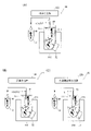
図1および図2に示すように、免疫測定装置100の状態確認方法は、少なくとも標識物質21を含む管理試料20が収容された第1容器11内の液相を第2容器12に移す工程(a)と、液相が移された第2容器12内の標識物質21を検出する工程(b)と、第2容器12内の標識物質21の検出結果に基づいて、複合体転移処理を行う免疫測定装置100の状態を判定する工程(c)と、を備える。すなわち、状態確認方法では、工程(a)として、免疫測定装置100による検体測定時の複合体転移処理と同様の液相の移し替え動作を実施する。そして、工程(b)として、移し替えた第2容器12中の管理試料20の測定を行う。工程(c)において、工程(b)により得られた検出結果に基づく状態判定を行う。
As shown in FIGS. 1 and 2, the method for confirming the state of the
工程(a)は、たとえば、免疫測定装置100が備える吸引管51により、第1容器11内の液相を吸引し、吸引した液相を第2容器12内に吐出する分注処理により行う。
Step (a) is performed, for example, by a dispensing process in which the liquid phase in the
工程(b)では、たとえば、免疫測定装置100が備える検出部により、第2容器12内の標識物質21を検出する。
In step (b), the
工程(c)では、たとえば、免疫測定装置100が備える判定部により、検出結果に基づく状態判定を行う。工程(c)は、たとえば免疫測定装置100と接続するコンピュータ、免疫測定装置100とネットワークを介して通信可能なサーバ装置などによっても実施されうる。
In step (c), for example, the determination unit provided in the
〈標識物質〉
標識物質は、検出または測定可能なシグナルを発することができる物質であれば特に限定されない。例えば、酵素、蛍光物質、放射性同位元素などが挙げられる。酵素としては、アルカリホスファターゼ、β-ガラクドシダーゼ、ペルオキシダーゼ、グルコースオキシダーゼ、チロシナーゼ、酸性ホスファターゼ、ルシフェラーゼなどが挙げられるが、特に限定されない。蛍光物質としては、フルオレセインイソチオシアネート(FITC)、クマリン、ローダミン、フルオレセイン、Cy3、Cy5、Hoechst 33342、4’,6-ジアミジノ-2-フェニルインドール(DAPI)、プロピジウムイオダイド(PI)、Alexa Fluor(モレキュラ・プローブス(Molecular Probes)社の登録商標)シリーズなどの蛍光色素、グリーン蛍光タンパク質(GFP)などの蛍光タンパク質などが挙げられるが、特に限定されない。放射性同位元素としては、125I、14C、32Pなどが挙げられるが、特に限定されない。
<Labeling substance>
The labeling substance is not particularly limited as long as it can emit a detectable or measurable signal. Examples include enzymes, fluorescent substances, and radioactive isotopes. Enzymes include, but are not limited to, alkaline phosphatase, β-galactosidase, peroxidase, glucose oxidase, tyrosinase, acid phosphatase, luciferase, and the like. Fluorescent substances include fluorescein isothiocyanate (FITC), coumarin, rhodamine, fluorescein, Cy3, Cy5,
なお、本明細書において、標識物質21は、測定試薬として用いられる標識抗体(被検物質と結合する抗体に標識物質が結合したもの)も含む概念である。
In the present specification, the
また、本明細書において、管理試料20に含まれる標識物質21は、検体の測定時に免疫複合体84に含まれる標識物質83(図4参照)と同一の標識物質であってもよいし、異なる標識物質であってもよい。
Further, in the present specification, the
標識物質の検出は、標識物質に用いる標識の種類に応じた適切な方法で行われればよく、検出方法は特に限定されない。標識物質に対応した検出手段を用いて標識物質の存在量を検出すればよい。たとえば、標識物質に用いる標識が酵素である場合、測定は、酵素に対して基質を反応させることにより発生する光、色などを測定することにより行うことができる。この場合の検出部として、光電子増倍管、分光光度計、ルミノメータなどが利用できる。また、標識物質が放射性同位体である場合、検出部としてシンチレーションカウンターなどが利用できる。標識物質が蛍光物質である場合、発光される蛍光が検出可能な蛍光検出器を利用して標識物質を検出することができる。 Detection of the labeling substance may be performed by an appropriate method according to the type of label used for the labeling substance, and the detection method is not particularly limited. The abundance of the labeling substance may be detected using detection means compatible with the labeling substance. For example, when the label used for the labeling substance is an enzyme, the measurement can be performed by measuring the light, color, etc. generated by reacting the substrate with the enzyme. A photomultiplier tube, a spectrophotometer, a luminometer, or the like can be used as the detector in this case. Moreover, when the labeling substance is a radioactive isotope, a scintillation counter or the like can be used as the detection unit. When the labeling substance is a fluorescent substance, the labeling substance can be detected using a fluorescence detector capable of detecting emitted fluorescence.
標識物質が酵素である場合、用いる酵素に応じて適宜公知の基質を選択すればよい。例えば、酵素としてアルカリホスファターゼを用いる場合の基質としてはCDP-Star(登録商標)、(4-クロロ-3-(メトキシスピロ[1,2-ジオキセタン-3,2’-(5’-クロロ)トリクシロ[3.3.1.13,7]デカン]-4-イル)フェニルリン酸2ナトリウム)、CSPD(登録商標)(3-(4-メトキシスピロ[1,2-ジオキセタン-3,2-(5’-クロロ)トリシクロ[3.3.1.13,7]デカン]-4-イル)フェニルリン酸2ナトリウム)などの化学発光基質;p-ニトロフェニルホスフェート、5-ブロモ-4-クロロ-3-インドリルリン酸(BCIP)、4-ニトロブルーテトラゾリウムクロリド(NBT)、ヨードニトロテトラゾリウム(INT)などの発光基質;4-メチルウムベリフェニル・ホスフェート(4MUP)などの蛍光基質;5-ブロモ-4-クロロ-3-インドリルリン酸(BCIP)、5-ブロモ-6-クロロ-インドリルリン酸2ナトリウム、p-ニトロフェニルリンなどの発色基質などが利用できる。 When the labeling substance is an enzyme, a known substrate may be appropriately selected according to the enzyme used. For example, CDP-Star (registered trademark), (4-chloro-3-(methoxyspiro[1,2-dioxetane-3,2′-(5′-chloro)trixyl) as a substrate when alkaline phosphatase is used as an enzyme [3.3.1.13,7]Decan]-4-yl)phenyl phosphate disodium), CSPD® (3-(4-methoxyspiro[1,2-dioxetane-3,2-( chemiluminescent substrates such as 5′-chloro)tricyclo[3.3.1.13,7]decane]-4-yl)phenylphosphate); p-nitrophenyl phosphate, 5-bromo-4-chloro- Luminescent substrates such as 3-indolyl phosphate (BCIP), 4-nitrobluetetrazolium chloride (NBT), iodonitrotetrazolium (INT); fluorescent substrates such as 4-methylumberiphenyl phosphate (4MUP); 5-bromo Chromogenic substrates such as 4-chloro-3-indolyl phosphate (BCIP), disodium 5-bromo-6-chloro-indolyl phosphate, p-nitrophenyl phosphate, and the like can be used.
検出により、標識物質21の存在量を反映した検出結果が取得される。検出結果は、標識物質21の存在量に対応する検出値として数値情報の形式で取得されうる。
A detection result reflecting the abundance of the
(標識物質が結合した固相担体を含む管理試料)
図1のように、管理試料20が、標識物質21が結合した固相担体22を含むものである場合、工程(a)を行う際に、固相担体22を集める処理が行われる。工程(a)により、固相担体22を残して液相が第1容器11から第2容器12に移動される。このため、第2容器12には、標識物質21が結合した固相担体22を含まない液相が収容される。
(Control Sample Containing Solid-Phase Carrier Bound with Labeling Substance)
As shown in FIG. 1, when the
〈固相担体〉
固相担体は、たとえば、免疫測定で用いられる公知の粒子である。粒子は、例えば、磁性粒子、ラテックス粒子、赤血球、ゼラチン粒子などが挙げられる。第1容器11中から液相を分離するため、固相担体22として磁性粒子を用いるのが好ましい。磁性粒子としては、磁性を有する材料を基材として含み、通常の免疫測定に用いられる粒子であればよい。例えば、基材としてFe2O3および/またはFe3O4、コバルト、ニッケル、フィライト、マグネタイトなどを用いた磁性粒子が利用できる。
<Solid phase carrier>
Solid phase carriers are known particles used in immunoassays, for example. Particles include, for example, magnetic particles, latex particles, red blood cells, gelatin particles, and the like. Magnetic particles are preferably used as the
なお、本明細において、管理試料20に含まれる固相担体22は、検体の測定時に免疫複合体84と結合する固相担体82と同一の固相担体であってもよいし、異なる固相担体であってもよい。
In the present specification, the solid-
標識物質と固相担体との結合は、化学結合などにより両者を直接結合してもよいし、捕捉物質を介して間接的に結合しても構わない。間接的な結合としては、たとえばビオチンとアビジン類、ハプテンと抗ハプテン抗体、ニッケルとヒスタチジンタグ、グルタチオンとグルタチオン-S-トランスフェラーゼなどの組み合わせが利用できる。なお、「アビジン類」とは、アビジンおよびストレプトアビジンを含むことを意味する。 The binding between the labeling substance and the solid phase carrier may be carried out by direct binding of the two by chemical bonding or the like, or by indirect binding via a capture substance. For indirect binding, combinations such as biotin and avidins, hapten and anti-hapten antibody, nickel and histidine tag, glutathione and glutathione-S-transferase can be used. In addition, "avidins" means including avidin and streptavidin.
一例として、ストレプトアビジンをコーティングした固相担体に、ビオチンを結合した蛍光色素を結合させることができる。このような、標識物質21が結合した固相担体22は、市販されているものを好適に用いることができる。
As an example, a biotin-conjugated fluorescent dye can be bound to a streptavidin-coated solid support. As such a
また、検体の代わりに、既知濃度の被検物質を精度管理試料(キャリブレーター)として使用して、各測定項目の測定用試薬を用いて測定処理を行うことによって、標識物質21が結合した固相担体22を形成してもよい。すなわち、標識物質21が結合した固相担体22は、図4に示した固相担体82上に、標識物質83、被検物質81および捕捉物質86からなる免疫複合体84を形成することによって作製されてもよい。この場合、後述するように免疫測定装置100に、免疫測定動作の一部または全部を実行させることにより、そのような物質を作製することができる。
In addition, instead of the sample, a test substance of known concentration is used as a quality control sample (calibrator), and measurement processing is performed using a measurement reagent for each measurement item, so that the solid phase to which the
図1において、工程(b)が実施されると、第2容器12中の標識物質21が検出される。免疫測定装置100の複合体転移処理を機能が正常である場合、使用上の許容上限量以上には、固相担体22が第2容器12へ持ち越されることはない。そのため、免疫測定装置100の固相担体22を集める機能が正常である場合、工程(b)による標識物質21の検出値は、標識物質21を含まないブランク試料を測定した場合と同等の低値となる。ここで、ブランク試料とは、標識物質21を含まない試料である。一方、免疫測定装置100の固相担体22を集める機能が異常である場合、たとえば第1容器11中で固相担体22が集まらずに分散した状態となっている場合、工程(a)により、標識物質21が結合した固相担体22が液相と共に第2容器12へ移される。そのため、免疫測定装置100の固相担体22を集める機能が異常である場合、工程(b)による標識物質21の検出値は、正常状態の検出値の許容範囲から外れた異常高値となる。
In FIG. 1, when step (b) is performed, the
このため、工程(c)において、工程(b)による検出結果が取得される。検出結果に基づいて、複合体転移処理における免疫測定装置100の状態が判定される。すなわち、検出結果から、複合体転移処理が正常に実施できたかどうかが判定される。判定する状態としては、「正常」か「異常」か、または「0(異常なし)」か「1(異常あり)」か、という2項分類でありうる。判定する状態としては、検出値に応じて正常または異常の程度を判定してもよい。たとえば正常状態のうちに、完全な正常範囲内、正常範囲外だが許容範囲内、許容範囲内だが異常値(許容範囲外)に近い境界範囲内、などの判定範囲を設定し、検出値に応じてどの範囲に属するかを判定してもよい。この場合、ユーザは、判定結果により、たとえば免疫測定装置100のメンテナンスの必要性を判断するための情報を得ることができる。
Therefore, in step (c), the detection result obtained in step (b) is obtained. Based on the detection result, the state of the
(標識物質が溶解した液体を含む管理試料)
図2のように、管理試料20が、標識物質21が溶解した液体を含むものである場合、工程(a)により、標識物質21を含む液相が第1容器11から第2容器12に移動される。このため、第2容器12には、標識物質21を含んだ液相が収容される。
(Control Sample Containing Liquid with Labeled Substance Dissolved)
As shown in FIG. 2, when the controlled
図2において、工程(b)が実施されると、第2容器12中の標識物質21が検出される。免疫測定装置100の第1容器11内の液相を第2容器12に移す機能が正常である場合、液相中の標識物質21が十分に第2容器12中に移される。そのため、免疫測定装置100の第1容器11内の液相を第2容器12に移す機能が正常である場合、工程(b)による標識物質21の検出値は、管理試料20に含まれる標識物質21の既知の濃度から予想される許容範囲内となる。一方、免疫測定装置100の第1容器11内の液相を第2容器12に移す機能が異常である場合、たとえば第1容器11中から第2容器12への液相の移送が行えなかった場合、工程(a)によっても、標識物質21を含む液相が第2容器12へ移されない。そのため、免疫測定装置100の第1容器11内の液相を第2容器12に移す機能が異常である場合、工程(b)による標識物質21の検出値は、標識物質21の既知の濃度から予想される許容範囲から外れた値となる。
In FIG. 2, when step (b) is performed, the
このため、工程(c)において、標識物質21が溶解した液体を含む管理試料20に対して工程(a)および工程(b)を行って得られた検出結果から、複合体転移処理における免疫測定装置100の状態が判定される。すなわち、複合体転移処理が正常に実施できたかが判定される。
Therefore, in step (c), from the detection results obtained by performing steps (a) and (b) on the
このように、本実施形態による免疫測定装置の状態確認方法では、標識物質21を含む管理試料20を収容する第1容器11に対して、複合体転移処理と同様の動作を行って、第2容器12に移された管理試料20中の標識物質21を検出できる。複合体転移処理が正常に行われなければ、予想される検出結果から外れた異常な検出結果が取得されることになる。これにより、第2容器12中の標識物質21の検出結果に基づいて、複合体転移処理が正常に実施できたかどうかなどの免疫測定装置100の状態を判定することができる。その結果、免疫測定装置100における免疫複合体転移法を実行するための機能の状態確認を簡便に行うことができる。
As described above, in the method for confirming the state of an immunoassay device according to the present embodiment, the same operation as the complex transfer processing is performed on the
〈固相担体を集める処理〉
図1のように、管理試料20が、標識物質21が結合した固相担体22を含む場合、第1容器11内の液相を第2容器12に移す工程(a)において、第1容器11内で標識物質21が結合した固相担体22を集める処理を行う。
<Treatment for collecting the solid-phase carrier>
As shown in FIG. 1, when the
固相担体22を集める処理は、たとえば、免疫測定装置100により第1容器11に対して遠心分離を行って固相担体22を容器底部に沈降させることにより行う。固相担体22が磁性粒子である場合、固相担体22を集める処理は、磁性粒子を磁力源52により集磁する処理を含む。たとえば、免疫測定装置100が備える磁力源52により磁性粒子が集磁される。
The process of collecting the
これにより、第1容器11中で標識物質21が結合した固相担体22を集めるので、たとえば標識物質21の検出値が上昇する場合には、液相を第2容器12に移す際に固相担体22が十分に集められておらず固相担体22も移されている可能性が高い。そのため、複合体転移処理における第1容器11内の固相担体22を集める機能が正常か否かを容易に確認できる。
As a result, the solid-
工程(a)および(b)の他に、以下のような工程があってもよい。 In addition to steps (a) and (b), the following steps may be included.
(複合体転移処理における異常を判定する工程)
たとえば、図1および図2において、免疫測定装置の状態確認方法は、第2容器12内の標識物質21の検出結果に基づいて、複合体転移処理における異常を判定する工程をさらに備える。上記の通り、工程(b)によって取得された検出値の大小を判定することによって、複合体転移処理における異常の有無を判定することができる。これにより、たとえば管理試料20中の標識物質21を検出した免疫測定装置100において検出結果の判定を行うことにより、複合体転移処理における異常があるか否かを判定することができる。判定は、たとえば、免疫測定装置100が備える判定部70(図3参照)や、免疫測定装置100と通信可能に接続されたホストコンピュータなどの外部装置などにより、行われうる。
(Step of judging abnormality in complex transfer treatment)
For example, in FIGS. 1 and 2, the immunoassay device state confirmation method further includes a step of determining abnormality in the complex transfer process based on the detection result of the
複合体転移処理を行うための機能は、具体的には、第1容器11中の固相担体22を集める機能、および、第1容器11内の液相を第2容器12に移す機能、を含む。そこで、複合体転移処理における異常を判定する工程は、第1容器11内の固相担体22を集める機能、および第1容器11内の液相を第2容器12に移し替える機能、の少なくともいずれかの異常を判定することを含む。
Specifically, the function for performing the complex transfer treatment includes the function of collecting the
複合体転移処理においては、免疫複合体84を含む液相を第2容器12に移して、第1容器11には固相担体22を残すために、第1容器11内の固相担体22を集める機能が正常か否か、が重要となる。図1に示したように、管理試料20が、標識物質21が結合した固相担体22を含むものである場合、工程(b)の検出結果に基づいて、第1容器11内の固相担体22を集める機能が正常か否かを判定することができる。
In the complex transfer treatment, in order to transfer the liquid phase containing the immune complex 84 to the
また、複合体転移処理において、第2容器12に移し替えた免疫複合体84を検出するために、第1容器11内の液相を第2容器12に移し替える機能が正常か否か、が重要となる。図2に示したように、管理試料20が、標識物質21が溶解した液体を含むものである場合、工程(b)の検出結果に基づいて、第1容器11内の液相を第2容器12に移し替える機能が正常か否かを判定することができる。上記構成によれば、これらの機能の少なくともいずれかの異常の有無を判定できるので、測定結果の信頼性を確保するために特に有用である。高い信頼性を確保するためには、第1容器11内の固相担体22を集める機能の判定と、第1容器11内の液相を第2容器12に移し替える機能の判定との、両方をそれぞれ行うことが好ましい。
In addition, in the complex transfer treatment, whether or not the function of transferring the liquid phase in the
複合体転移処理における異常を判定する工程を行う場合、第2容器12内における標識物質21の検出値が基準値V1を超えること、または検出値が基準値V1を下回ること、に基づいて異常を判定する。これにより、予め管理試料20を測定して得られる検出値から正常と異常とを区別するための基準値V1を設定しておくことにより、検出値と基準値V1とを比べるだけで、複合体転移処理の異常判定を容易に行うことができる。
When performing the step of determining abnormality in the complex transfer treatment, abnormality is detected based on whether the detected value of the
〈管理試料を第1容器に分注する工程〉
図1および図2において、第1容器11内の液相を第2容器12に移す工程の前に、免疫測定装置100により、管理試料20を第1容器11に分注する工程をさらに備え得る。たとえば免疫測定装置100は、予め管理試料20を収容した容器(図示せず)から管理試料20を吸引管51により吸引して、第1容器11内に吐出する。これにより、免疫測定装置100のユーザやサービススタッフが事前に管理試料20を第1容器11に準備しておかなくても、免疫測定装置100によって容易に、管理試料20を第1容器11に収容させることができる。
<Step of dispensing the control sample into the first container>
In FIGS. 1 and 2, before the step of transferring the liquid phase in the
[免疫測定装置の概要]
次に、図3を参照して、一実施形態による免疫測定装置100の概要について説明する。
[Outline of immunoassay device]
Next, an overview of the
免疫測定装置100は、抗原抗体反応を利用して検体中の被検物質を測定する装置である。免疫測定装置100は、免疫複合体転移法による複合体転移処理を行う。すなわち、免疫測定装置100は、図4に示したように、検体中の被検物質81と標識物質83とを含み固相担体82に担持された免疫複合体84を収容する第1容器11内で、免疫複合体84を固相担体82から遊離させ、第1容器11内の液相を第2容器12に移す複合体転移処理を行う免疫測定装置100である。
The
図3に示すように、免疫測定装置100は、少なくとも標識物質21を含む管理試料20が収容された第1容器11内の液相を第2容器12に移す処理を行う機構部50と、液相が移された第2容器12内の標識物質21を検出する検出部60と、検出部60の検出結果に基づいて、複合体転移処理における異常を判定する判定部70と、を備える。
As shown in FIG. 3, the
機構部50は、少なくとも複合体転移処理を実行する機能を有する。すなわち、機構部50は、第1容器11内の液相を第2容器12に移す処理を行うように構成されている。機構部50は、複合体転移処理のみならず、免疫測定のために必要な処理を、反応容器に対して実施する機能を備え得る。たとえば、機構部50は、第1容器11内で、固相担体22上に検体中の被検物質81および標識物質21を含む免疫複合体を形成させる処理を行い得る。
The
機構部50は、免疫測定装置100が行う処理工程の種類および数に応じて、1または複数の処理ユニットを含むことができる。1つの処理ユニットが、1種類の処理工程を実施してもよいし、複数種類の処理工程を実施できる処理ユニットであってもよい。
The
機構部50は、たとえば、第1容器11内の液相を吸引し、吸引した液相を第2容器12に吐出する吸引管51を含む。吸引管51は、たとえば定量ポンプなどの圧力源(図示せず)に接続され、先端から所定量の液体を吸引し、定量分注できる。
The
管理試料20が、標識物質21が結合した固相担体22を含む場合、機構部50は、第1容器11内で標識物質21が結合した磁性粒子を集磁する磁力源52を含む。磁力源52は、第1容器11の近傍に位置付けられる。磁力源52の磁力により、磁性粒子を集磁できる。集磁とは、磁力を作用させて磁性体を集めることである。磁力源52は、たとえば、第1容器11内の磁性粒子に対して磁力を作用させ、磁性粒子を第1容器11の内側面や底部などの所定位置に集磁する。磁力源52としては、たとえば永久磁石または電磁石が採用できる。
When the controlled
たとえば、機構部50は、第1容器11に検体を分注するための検体分注部を含んでもよい。この場合、機構部50は、被検物質81を含む検体を分注する工程を実施できる。予め検体が分注された第1容器11を機構部50が処理する場合、機構部50に検体分注部を設ける必要はない。
For example, the
また、機構部50は、第1容器11に試薬を分注するための試薬分注部を含んでもよい。この場合、機構部50は、磁性粒子などの固相担体22、82を含む固相試薬を分注する工程、標識物質21、83を含む標識試薬を分注する工程、および、遊離試薬85を分注する工程を実施できる。これらの試薬が予め分注された第1容器11を機構部50が処理する場合、機構部50に試薬分注部を設ける必要はない。
Further, the
第1容器11に分注される各種試薬は、液体試薬であり、種類毎にそれぞれ別々の試薬容器に収容される。固相試薬は液体中に磁性粒子などの固相担体22、82を含んだ液体試薬であり、標識試薬は液体中に標識物質21、83を含んだ液体試薬である。遊離試薬85は、免疫複合体84と固相担体82との結合を解消するための成分を含んだ液体試薬である。
Various reagents to be dispensed into the
遊離試薬85は、被検物質81と標識物質83とを含む免疫複合体84と固相担体82との結合を解消させ、免疫複合体84を固相担体82から遊離させる。固相担体82と被検物質81とが結合する場合、遊離試薬85は、固相担体82と被検物質81との結合を解消させる。固相担体82が捕捉物質86を介して被検物質81と結合する場合、遊離試薬85は、固相担体82と捕捉物質86との結合、または、被検物質81と捕捉物質86との結合を解消させればよい。遊離試薬85は、免疫複合体84と固相担体82との結合の種類に応じて選択される。
The
たとえば、免疫複合体84と固相担体82との結合がハプテン-抗ハプテン抗体による結合である場合、ハプテンまたはハプテン誘導体が遊離試薬85として利用できる。また、免疫複合体84と固相担体82との結合が、イオン結合による結合である場合は、遊離試薬85としてイオンを含む溶液が利用できる。また、免疫複合体84と固相担体82との結合が、分離可能結合としてリガンド-レセプターによる結合である場合は、遊離試薬85としてリガンドまたはリガンド類似体が利用できる。免疫複合体84と固相担体82との結合が、分離可能結合としてレクチン-糖鎖による結合である場合は、遊離試薬85として糖質が利用できる。免疫複合体84と固相担体82との結合が、ビオチン-アビジンにより結合している場合は、遊離試薬85としてビオチンが利用できる。
For example, if the binding between immune complex 84 and
また、機構部50は、第1容器11中の試料を加温して反応させるための反応部を含んでもよい。この場合、機構部50は、免疫複合体84を形成させる処理や、免疫複合体84を遊離させる処理に際して、反応に適した温度環境で試料の反応を促進させることができるので、効率的に処理ができる。第1容器11中の試料を加温しなくても反応が十分進行する場合や、機構部50全体が所定温度の恒温槽として構成されている場合などには、機構部50に反応部を設ける必要はない。
In addition, the
検出部60は、第2容器12に分注された液相中の標識物質21、83を検出する機能を備える。上記の通り、検出は、標識物質21、83の種類に応じた適切な方法で行われればよく、検出方法は特に限定されない。検出部60として、光電子増倍管、分光光度計、ルミノメータなどが利用できる。蛍光を検出する場合、検出部60は、励起光を照射するための光源を備えうる。また、標識物質が放射性同位体である場合、検出部60としてシンチレーションカウンターなどが利用できる。
The
判定部70は、検出部60の検出結果を取得する。判定部70は、たとえば、CPUなどのプロセッサと、ハードディスクドライブやフラッシュメモリなどの記憶部とを含むコンピュータにより構成される。プロセッサは、記憶部に記憶された制御プログラムを実行することにより、免疫測定装置100の判定部70として機能する。判定部70は、検出部60の検出結果に基づいて、複合体転移処理における異常を判定する。
The
本実施形態による免疫測定装置100は、上記の構成によって、図1および図2の少なくとも一方に示した免疫測定装置100の状態確認方法を実施する。これにより、標識物質21を含む管理試料20を収容する第1容器11に対して、複合体転移処理と同様の液相の移し替え動作を行って、第2容器12に移された管理試料20中の標識物質21を検出できる。複合体転移処理が正常に行われなければ、予想される検出結果から外れた異常な検出結果が取得されることになる。これにより、第2容器12中の標識物質21の検出結果から、複合体転移処理が正常に実施できたかどうかを確認することができるので、免疫測定装置における免疫複合体転移法を実行するための機能の状態確認を簡便に行うことができる。
The
[免疫測定装置の具体的な構成例]
次に、図5を参照して、免疫測定装置100の具体的な構成例について詳細に説明する。
[Specific Configuration Example of Immunoassay Device]
Next, a specific configuration example of the
免疫測定装置100は、機構部50、検出部60、および判定部70を備える。図5の構成例では、免疫測定装置100は、免疫測定結果を分析するための分析部110を備えている。判定部70は、分析部110が実行する機能の一部として実現されている。
機構部50は、検体分注部120と、試薬分注部130と、容器供給部140と、試薬庫150と、反応部160と、BF分離部170とを含む。また、機構部50は、これらの各部に容器を搬送する容器移送部180を含む。また、免疫測定装置100は、検体搬送部190と、機構部50および検出部60を収容する筐体105とを備える。
The
筐体105は、免疫測定装置100の各部を内部に収容する箱状形状を有する。なお、筐体105は、1つまたは複数の階層で構成され得る。
The
検体搬送部190は、被検体から採取された検体を、検体分注部120による吸引位置まで搬送するように構成されている。検体搬送部190は、検体を収容した検体容器191(図6参照)が複数設置されたラックを所定の検体吸引位置まで搬送できる。
The
検体分注部120は、検体搬送部190により搬送された検体を吸引し、吸引した検体を第1容器11に分注できる。図6に示すように、検体分注部120は、吸引および吐出を行うための流体回路に接続された吸引管121と、吸引管121を移動させる移動機構(図示せず)とを含む。検体分注部120は、たとえば図示しないチップ供給部から分注チップ122を吸引管121の先端に装着して、搬送された検体容器191中の検体を分注チップ122内に所定量吸引する。検体分注部120は、吸引した検体を所定の検体分注位置に配置された第1容器11に分注する。分注後、検体分注部120は、分注チップ122を吸引管121の先端から取り外して廃棄する。
The
容器供給部140は、未使用の反応容器を複数貯留できる。すなわち、容器供給部140は、未使用の第1容器11および第2容器12を複数貯留して、所定の容器供給位置にそれぞれ供給できる。この構成例では、第1容器11および第2容器12として、同一形状および同一材質の反応容器が用いられる。つまり、容器供給部140から供給された未使用の反応容器は、第1容器11としても第2容器12としても使用できる。なお、第1容器11および第2容器12が共通して該当し、区別する必要がない場合は、単に「反応容器10」という。
The
容器移送部180は、反応容器10を移送できる。容器移送部180は、容器供給位置から空の容器を取得し、検体分注部120、試薬分注部130、反応部160、BF分離部170、検出部60などの各々の処理位置に容器を移送する。容器移送部180は、たとえば容器を把持するキャッチャまたは容器の設置穴を有する保持部と、キャッチャまたは保持部を移動させる移動機構とにより構成される。移動機構は、たとえば直線移動可能な1または複数の直動機構により、1軸または複数軸方向に移動する。移動機構は、たとえば上下方向および水平2方向の直交3軸方向に移動できる。移動機構は、回転軸回りに水平回転するアーム機構や、多関節ロボット機構を含んでいてもよい。容器移送部180は、筐体105内の各ユニットの処理位置の配置に応じて、1つまたは複数設けられる。
The
反応部160は、ヒーターおよび温度センサを備え、反応容器10を保持して容器内に収容された試料を加温して反応させる。加温により、容器内に収容された検体および試薬が反応する。反応部160は、筐体105内に1つまたは複数設けられる。反応部160は、筐体105に固定的に設置されていてもよいし、筐体105内で移動可能に設けられていてもよい。反応部160が移動可能に構成される場合、反応部160は、容器移送部180の一部としても機能しうる。
The
試薬庫150は、箱状形状を有し、内部に容器保持部151と冷却機構とを有する。容器保持部151は試薬容器155を保持する。冷却機構は、試薬容器155内の試薬を保管に適した一定温度に保冷する。試薬庫150は、上面に、試薬分注部130が試薬庫150の内部へ進入するための複数の孔部152を有する。
The
容器保持部151は、複数の試薬容器155を円周方向に並べて保持するように形成されている。容器保持部151は、複数の試薬容器155を半径方向に並べて保持できる。つまり、容器保持部151は、円周状に並ぶ複数の試薬容器155の列を、同心円状に径方向に並べて配列できる。容器保持部151は、同心円状の複数の試薬容器155の列を、独立して周方向に回転できる。これにより、容器保持部151は、試薬分注部130に応じて設けられた複数の孔部152の各々の直下の位置に、対応する試薬容器155の列のうちから選択された所望の試薬容器155を配置できる。その結果、孔部152の直下の位置に配置した試薬容器155内の試薬が試薬分注部130により吸引される。容器保持部151には、後述するr1試薬、r4試薬、r5試薬、r6試薬、r7試薬をそれぞれ収容する試薬容器155がセットされる。試薬容器155は、複数の収容室を有して複数種類の試薬を収容できる構造であってもよい。
The
試薬分注部130は、試薬容器155内の試薬を吸引し、吸引した試薬を反応容器10に分注する。試薬分注部130は、試薬の吸引および吐出を行うための吸引管131を、孔部152と、所定の試薬分注位置との間で水平方向に移動できる。また、図7に示すように、試薬分注部130は、吸引管131を上下方向に移動させ、孔部152の上方から孔部152を通過させて試薬容器155の内部に進入させることができ、孔部152の上方位置まで吸引管131を退避させることができる。吸引管131は、図示しない流体回路と接続され、容器保持部151の試薬容器155から所定量の試薬を吸引し、試薬分注位置に移送された反応容器10に試薬を分注する。
The
試薬分注部130は、たとえば、1つまたは複数設けられる。図5の例では、試薬分注部130は、試薬庫150の上に3つ設けられている。3つの試薬分注部130は、それぞれr1試薬、r4試薬、r5試薬、r6試薬、r7試薬のいずれを分注するかが予め設定されているが、どの試薬分注部130によりどの試薬を分注するかは、特に限定されない。また、機構部50は、R4試薬を分注するためのR4試薬分注部134およびR5試薬を分注するためのR5試薬分注部135を含む。
One or a plurality of
R4試薬分注部134およびR5試薬分注部135は、試薬庫150からは離間した位置に設けられている。R4試薬分注部134およびR5試薬分注部135は、それぞれR4試薬およびR5試薬を収容した試薬容器(図示せず)と送液チューブを介して接続されており、容器移送部180によって移送された反応容器10中に試薬を吐出できる。
The R4
BF分離部170は、反応容器10から、液相と固相とを分離するBF分離を実行する機能を有する。免疫測定装置100において、BF分離部170は、1つまたは複数設けられる。図8に示すように、BF分離部170は、集磁部173により磁性粒子を集磁した状態で、吸引管171により反応容器10内の液体成分を吸引して、吐出管172により洗浄液を供給する。吸引管171および吐出管172は、それぞれ図示しない流体回路に接続されている。これにより、液体成分に含まれる不要物質を磁性粒子から分離して除去できる。
The
機構部50は、複合体転移処理を行う機能を有する。
The
図9に示すように、機構部50は、第1容器11内で標識物質21が結合した磁性粒子を集磁する磁力源52を含む。磁力源52は、たとえば第1容器11を保持するための保持孔211が形成された保持部材210に設けられる。磁力源52は、たとえば永久磁石により構成される。保持部材210は、筐体105内に固定的に設置されていてもよいし、移動可能に構成され、容器移送部180の一部として機能してもよい。
As shown in FIG. 9 , the
機構部50は、第1容器11内の液相を吸引し、吸引した液相を第2容器12に吐出する吸引管51を含む。吸引管51は、保持部材210に保持された第1容器11中から液相を吸引して、容器移送部180または別の容器保持部(図示せず)に保持された第2容器12中に、吸引した液相を分注する。
The
複合体転移処理における液相の移し替えは、吸引管を備える構成によって実施される。たとえば、図9(A)に示すように、複合体転移処理は、検体分注部120の吸引管121によって実行することができる。吸引管121が複合体転移処理を行う吸引管51としても機能する。図9(B)に示すように、複合体転移処理は、試薬分注部130の吸引管131によって実行することができる。吸引管131が複合体転移処理を行う吸引管51としても機能する。図9(C)に示すように、機構部50は、複合体転移処理を行うための専用の免疫複合体分注部220を備えていてもよい。その場合、免疫複合体分注部220が備える吸引管51によって、第1容器11内の液相が吸引され、吸引した液相が第2容器12に吐出される。
Transfer of the liquid phase in the complex transfer treatment is carried out by a structure provided with a suction tube. For example, as shown in FIG. 9A, complex transfer processing can be performed by
図10に示すように、検出部60は、光電子増倍管などの光検出器61を含む。検出部60は、第2容器12を内部に受け入れて、検体の被検物質81に結合する標識物質83(図4参照)と発光基質との反応過程で生じる光を光検出器61により検出する。検出部60は、光検出器61で検出された光子の数を計数して、検出値として出力する。
As shown in FIG. 10, the
図4に戻り、分析部110は、たとえば、パーソナルコンピュータにより構成される。分析部110は、たとえば、CPUなどのプロセッサ111と、ROM、RAMおよびハードディスクなどの記憶部112とを含んで構成される。プロセッサ111は、記憶部112に記憶された制御プログラムを実行することにより、免疫測定装置100の分析部110として機能する。
Returning to FIG. 4, the
分析部110は、機構部50と電気的に接続され、検体の測定や、免疫測定装置100の状態確認を実行するように機構部50を制御する。分析部110は、図示しないホストコンピュータから取得した測定オーダに従って機構部50に検体測定を実施させ、検出部60による検出結果を分析する。すなわち、分析部110は、検出部60による検出値と、予め作成された検量線とを比較することにより、試料中の被検物質81の存在量(すなわち、被検物質81と結合した標識物質83の存在量)を取得する。分析部110は、判定部70を含む。つまり、分析部110は、プロセッサ111が制御プログラムを実行することにより、判定部70としても機能する。判定部70として機能する専用のプロセッサを設けてもよい。
The
判定部70は、機構部50による第1容器11内の固相担体22を集める機能、および機構部50による第1容器11内の液相を第2容器12に移し替える機能、の少なくともいずれかの異常を判定する。これにより、複合体転移処理において固相担体22を集める機能、および液相を第2容器12に移し替える機能の少なくともいずれかの異常の有無を判定できるので、測定結果の信頼性を確保するために特に有用である。
The
具体的には、判定部70は、標識物質21が結合した磁性粒子を含む管理試料に対する検出結果に基づいて、磁力源52(図9参照)による集磁機能の異常を判定する。これにより、第1容器11中で標識物質21が結合した固相担体22を集磁するので、たとえば標識物質21の検出値が上昇する場合には、液相を第2容器12に移す際に固相担体22が十分に集磁できておらず固相担体22も移されている可能性が高い。そのため、複合体転移処理における磁力源52による集磁機能が正常であるか異常であるかを容易に判定できる。
Specifically, the determining
また、判定部70は、標識物質21が溶解した溶液を含む管理試料に対する検出結果に基づいて、吸引管51(図9参照)による分注機能の異常を判定する。これにより、第1容器11中で標識物質21が液相として存在するので、たとえば標識物質21の検出値が上昇しない場合には、液相を第2容器12に分注する際に、液相の吸引および液相の吐出を行う吸引管51による分注機が正常でない可能性が高い。そのため、複合体転移処理における吸引管51による分注機能の異常の有無を容易に確認できる。
Further, the
(免疫測定の概要)
図5に示す構成例では、図4に示したように、r1試薬~r7試薬と、R4試薬およびR5試薬とを用いて免疫測定が行われる。ここでは、免疫測定の一例として、被検物質81がB型肝炎表面抗原(HBsAg)である例について説明する。
(Overview of immunoassay)
In the configuration example shown in FIG. 5, as shown in FIG. 4, immunoassays are performed using the r1 to r7 reagents and the R4 and R5 reagents. Here, as an example of immunoassay, an example in which the
まず、試薬分注部130により、第1容器11にr1試薬が分注される。r1試薬は、標識物質83を含有する標識試薬である。標識物質83は、被検物質81と反応して結合する。図4の例では、標識物質は、ALP(アルカリホスファターゼ)標識抗体である。それぞれの試薬の分注後には、反応部160において反応容器10内の試料が所定時間、所定温度に加温される。以下の説明では、反応部160については説明を省略する。
First, the
次に、検体分注部120により、第1容器11に被検物質81を含む検体が分注される。被検物質81は、標識物質83と結合する。なお、被検物質81によっては、予め抗体が結合した状態で検体中に存在する抗原を、抗体から遊離させる前処理として検体をアルカリ変性させる試薬(r2試薬)や、検体のアルカリを中和する試薬(r3試薬)などがさらに分注されてもよい。
Next, the
次に、試薬分注部130により、第1容器11にr4試薬が分注される。r4試薬は、被検物質81と反応して結合する捕捉物質86を含有する捕捉試薬である。捕捉物質86は、捕捉物質86が後述する第1固相担体82aと結合するための第1結合物質86aと、捕捉物質86が後述する第2固相担体82bと結合するための第2結合物質86bとを含む。第1結合物質86aと第2結合物質86bとは、互いに異なる結合能によって、固相担体と結合する物質である。
Next, the r4 reagent is dispensed into the
図4の例では、捕捉物質86は、DNP(ジニトロフェニル基)とビオチンとで修飾された抗体(DNP/biotin抗体)である。すなわち、捕捉物質86には、第1結合物質86aとしてDNP(ジニトロフェニル基)が修飾され、第2結合物質86bとしてビオチンが修飾されている。
In the example of FIG. 4, the
次に、試薬分注部130により、第1容器11にr5試薬が分注される。r5試薬は、固相担体82を含有する固相試薬である。具体的には、r5試薬は、固相担体82として、第1固相担体82aを含有する。第1固相担体82aは、磁性粒子であり、具体的には、抗DNP抗体を固定した磁性粒子(抗DNP抗体化磁性粒子)である。抗ハプテンである抗DNP抗体化磁性粒子の抗DNP抗体は、ハプテンである捕捉物質86のDNPと反応して結合する。この結果、第1固相担体82a上に、被検物質81と、標識物質83と、捕捉物質86とを含む免疫複合体84が形成される。
Next, the
第1固相担体82a上に形成された免疫複合体84と、未反応の標識物質83とは、1次BF分離処理によって分離される。1次BF分離処理によって、未反応の標識物質83などの不要成分が、第1容器11中から除去される。1次BF分離処理は、BF分離部170(図8参照)により行われる。
The immune complex 84 formed on the first
1次BF分離処理の次に、試薬分注部130により、第1容器11にr6試薬が分注される。r6試薬は、遊離試薬85である。図4の例では、遊離試薬85としてDNP-Lys(DNP-Lysine)を用いる。DNP-Lysは、第1固相担体82aである抗DNP抗体化磁性粒子と反応し結合する。そのため、第1容器11にr6試薬が分注されると、捕捉物質86のDNPと第1固相担体82aとの結合と、遊離試薬85(DNP-Lys)と第1固相担体82aとの結合とが競合し、捕捉物質86と第1固相担体82aとの間の結合が解消される。その結果、第1固相担体82aから免疫複合体84が遊離する。
After the primary BF separation process, the
次に、複合体転移処理が行われる。すなわち、r6試薬によって遊離した免疫複合体84を含む液相は、吸引管51によって第1容器11から吸引され、第2容器12に分注される。
Next, complex transfer processing is performed. That is, the liquid phase containing the immune complex 84 liberated by the r6 reagent is sucked from the
複合体転移処理により、第1固相担体82aから遊離した免疫複合体84を含む液相が第1容器11から第2容器12に移し替えられる。免疫複合体84を含む液相が吸引された後の第1容器11には、第1固相担体82aが残留する。この結果、第1固相担体82aに非特異的に結合した標識物質83が、免疫複合体84から分離される。
The complex transfer treatment transfers the liquid phase containing the immune complex 84 released from the first
免疫複合体84が分注された第2容器12には、次に試薬分注部130により、r7試薬が分注される。r7試薬は、第2固相担体82bを含有する。第2固相担体82bは、捕捉物質86の第2結合物質86bと結合する。第2固相担体82bは、磁性粒子であり、具体的には、ビオチンと結合するストレプトアビジンを固定した磁性粒子(StAvi結合磁性粒子)である。StAvi結合磁性粒子のストレプトアビジンは、第2結合物質86bであるビオチンと反応して結合する。この結果、被検物質81と、標識物質83と、捕捉物質86とを含む免疫複合体84が第2固相担体82bと結合する。
Next, the r7 reagent is dispensed by the
第2固相担体82bと結合した免疫複合体84と、免疫複合体84が形成された第2固相担体82b以外の不要成分とは、2次BF分離処理によって分離され、不要成分が第2容器12中から除去される。不要成分は、たとえば、液相中に含まれていた遊離試薬85や、被検物質81と結合せずに、免疫複合体84とともに液相中に含まれていた標識物質83などである。2次BF分離処理は、BF分離部170(図8参照)により行われる。
The immune complex 84 bound to the second solid-
その後、R4試薬分注部134およびR5試薬分注部135により、第2容器12にR4試薬およびR5試薬がそれぞれ分注される。R4試薬は、緩衝液を含有する。第2固相担体82bと結合した免疫複合体84が緩衝液中に分散される。R5試薬は、化学発光基質を含有する。R4試薬に含有される緩衝液は、免疫複合体84に含まれる標識物質83の標識(酵素)と基質との反応を促進する組成を有する。標識に対して基質を反応させることによって光が発生し、発生する光の強度が検出部60(図10参照)により測定される。
Thereafter, the R4
(免疫測定装置の状態確認方法)
次に、図5に示した免疫測定装置100の具体的構成例における状態確認方法について説明する。
(Method for confirming the state of the immunoassay device)
Next, a state confirmation method in the specific configuration example of the
以下の例において、管理試料20に含まれる標識物質21が酵素である。第2容器12内の標識物質21を検出する工程(b)は、酵素の基質を第2容器12に添加し、酵素反応により生じた反応産物から生じる信号を測定することにより行われる。
In the following example, the
〈集磁機能の確認〉
図12~図14を参照して、免疫測定装置100の集磁機能の確認を行う例を示す。図12~図14の例では、管理試料20は、標識物質21が結合した固相担体22を含み、固相担体22は磁性粒子である。固相担体22を集める処理は、磁性粒子を磁力源52により集磁する処理を含む。状態確認方法は、第2容器12内の標識物質21の検出結果に基づいて、磁力源52による集磁機能の異常を判定する工程を備える。これにより、標識物質21が結合した磁性粒子を集磁するため、第2容器12内の標識物質21の検出値に基づいて、磁力源52による集磁機能が正常であるか異常であるかを容易に判定できる。
<Confirmation of magnet collection function>
12 to 14, an example of confirming the magnet collecting function of the
具体的には、図11に示すように、判定部70が、標識物質21の検出値が基準値V1を上回る場合に、磁力源52による集磁機能の異常があると判定する。すなわち、標識物質21の検出値が基準値V1を上回る場合には、液相を第2容器12に移す際に磁性粒子を十分に集磁できていない可能性が高い。これにより、検出値と基準値V1との対比により、磁力源52による集磁機能を容易に判定できる。
Specifically, as shown in FIG. 11, the
集磁機能の確認を行う場合の基準値V1は、集磁されずに第2容器12に移される磁性粒子の許容上限量に相当する標識物質21の予想検出値である。これにより、許容上限量を超える量の磁性粒子が第2容器12に移されている場合に、磁力源52による集磁機能が異常であることを容易に判定できる。そのため、許容上限量を超えないことが確認されることにより、測定結果の信頼性を確保することができる。
The reference value V1 for confirming the magnetism collecting function is an expected detection value of the
(実施形態1)
図12の例では、管理試料20は、被検物質81と結合せずに標識物質21と結合した第3固相担体23を含む。液相中には、標識物質21が実質的に含まれていない。第3固相担体23は、たとえば、予め標識物質21が固定された磁性粒子である。第3固相担体23は、被検物質81に対する結合能を有していない。すなわち、集磁機能の確認を行う場合の第3固相担体23は、上記検体の測定を行う場合のr5試薬に含まれる第1固相担体82a、およびr7試薬に含まれる第2固相担体82bとは別個に用意された精度管理試薬に含まれるものである。
(Embodiment 1)
In the example of FIG. 12, the
これにより、免疫測定装置100の状態確認のために専用の試薬として、被検物質81を含まない第3固相担体23を用いて、固相担体22を集める機能の確認を行うことができる。固相担体22が標識物質21だけでなく被検物質81とも結合させる場合、被検物質81の種類に応じて結合可能な固相担体22および標識物質21を複数種類用意するのに対して、被検物質81を含まない第3固相担体23では、被検物質81の種類によらずに免疫測定装置100の状態確認を行うことができる。そのため、免疫測定装置100の状態確認をより簡便に行うことができる。
As a result, the third solid-
図12の例では、第1容器11内に、標識物質21と結合した第3固相担体23を含む管理試料20が収容される。管理試料20は、機構部50により、第1容器11に分注される。たとえば、管理試料20は、検体容器191と同様に所定の管理試料容器に収容された状態で、検体搬送部190にセットされ、検体分注部120により第1容器11に分注される。また、たとえば、管理試料20は、試薬容器155と同様に所定の管理試料容器に収容された状態で、試薬庫150にセットされ、試薬分注部130により第1容器11に分注される。
In the example of FIG. 12, the controlled
管理試料20が収容された第1容器11内の液相を第2容器12に移す工程(a)の際に、第1容器11内の第3固相担体23が、磁力源52によって第1容器11内に集磁される。集磁された状態で、吸引管51により、第1容器11内の液相が吸引されて第2容器12内に分注される。第3固相担体23は、第1容器11内に集磁されたまま残される。
During the step (a) of transferring the liquid phase in the
次に、検出部60により、液相が移された第2容器12内の標識物質21を検出する工程(b)が行われる。工程(b)により、標識物質21の存在量を示す検出値が取得される。
Next, a step (b) of detecting the
図12の例では、図4に示したr1試薬、検体、r4試薬、r5試薬、r6試薬、r7試薬の分注動作をスキップすることができる。免疫測定装置100の分注動作をスキップしない場合、それぞれの試薬および検体に代えて、緩衝液などの抗原抗体反応を生じない代替液体を分注してもよい。また、図12の例では、図4に示した1次BF分離処理および2次BF分離処理がスキップされる。代替液体の分注を行う場合、BF分離も行ってもよい。図12では、図4に示したr6試薬の分注タイミングで、管理試料20の分注を行う例を示しているが、管理試料20は複合体転移処理の前であればどのタイミングで分注してもよい。
In the example of FIG. 12, the pipetting operations of the r1 reagent, the sample, the r4 reagent, the r5 reagent, the r6 reagent, and the r7 reagent shown in FIG. 4 can be skipped. If the dispensing operation of the
(実施形態2)
図13の例では、状態確認方法は、第1容器11内の液相を第2容器12に移す工程の前に、第1容器11内で、既知濃度の被検物質81を含む試料、被検物質81と結合する標識物質83、被検物質81と結合する捕捉物質86、および捕捉物質86と結合する固相担体82とを接触させる工程を備える。つまり、状態確認方法においても、検体を測定する場合と同様に、被検物質81を含む精度管理試料と、各種試薬とを第1容器11内に分注して、管理試料20を調製する。この結果、管理試料20は、被検物質81、標識物質83および捕捉物質86を含む免疫複合体84と結合した固相担体82を含む。つまり、図13は、免疫測定装置100の状態確認方法に用いる標識物質21および固相担体22として、実際の検体測定で用いる標識物質83および固相担体82を使用する例を示す。
(Embodiment 2)
In the example of FIG. 13 , the state confirmation method includes, before the step of transferring the liquid phase in the
これにより、被検物質81を含む検体を実際に測定する場合と同様の処理工程によって、標識物質83が結合した固相担体82を第1容器11中に形成することができる。液相中には、標識物質83が実質的に含まれない。
As a result, the solid-
図13の例では、まず、第1容器11に標識物質83を含むr1試薬が分注される。次に、既知濃度の被検物質81を含む精度管理試料が分注される。次に、捕捉物質86を含むr4試薬が分注される。そして、第1固相担体82aを含むr5試薬が分注される。この結果、被検物質81、標識物質83および捕捉物質86を含む免疫複合体84と第1固相担体82aとが結合する。試薬の分注は試薬分注部130により行われ、精度管理試料の分注は検体分注部120により行われる。
In the example of FIG. 13, first, the r1 reagent containing the
このように、図13の例では、管理試料20は、検体の測定時において複合体転移処理前に第1容器11に分注される第1固相担体82aを含む。つまり、管理試料20は、r5試薬に含まれる磁性粒子である第1固相担体82aを含む。これにより、被検物質81を含む検体を実際に測定する場合に分注される第1固相担体82aを用いて、標識物質83が結合した固相担体82を第1容器11中に形成することができる。すなわち、免疫測定装置100の状態確認のために専用の固相担体22を別途用意する必要がないので、免疫測定装置100の利便性を向上させることができる。
Thus, in the example of FIG. 13, the
次に、BF分離部170により1次BF分離処理が行われる。つまり、図13の例では、状態確認方法は、第1容器11内の液相を第2容器12に移す工程の前に、被検物質81、標識物質83、捕捉物質86を含む免疫複合体84と結合した固相担体82と、液相とを分離するBF分離を行う工程を備える。これにより、BF分離によって、固相担体82と結合しなかった液相中の標識物質83を、固相担体から分離して排除できる。そのため、第1容器11内の液相を第2容器12に移す工程において、液相中に標識物質83が混ざることを抑制できるので、免疫測定装置100の状態確認のための標識物質83の検出精度を向上させることができる。
Next, the
1次BF分離処理の後、試薬分注部130により、遊離試薬85を含まない液相25が第1容器11に分注される。つまり、検体の測定時には、複合体転移処理において、第1容器11に遊離試薬85が分注されることにより、免疫複合体84が固相担体22から遊離される。これに対して、図13の例では、状態確認方法は、BF分離を行う工程の後、第1容器11内の液相を第2容器12に移す工程の前に、遊離試薬85を含まない液相を第1容器11に分注する工程を備える。
After the primary BF separation process, the
遊離試薬85を含まない液相25は、特に限定されないが、たとえば緩衝液である。これにより、実際の検体測定時に遊離試薬85を分注するのと同様の動作で、免疫測定装置100の状態確認が行われる。この場合、液相25は遊離試薬85を含まないので、標識物質83と固相担体82とは結合したままとなる。
次に、複合体転移処理が行われる。管理試料20が収容された第1容器11内の液相を第2容器12に移す工程(a)の際に、第1容器11内の第1固相担体82aが、磁力源52によって第1容器11内に集磁される。集磁された状態で、吸引管51により、第1容器11内の液相が吸引されて第2容器12内に分注される。第1固相担体82aは、第1容器11内に集磁されたまま残される。第1固相担体82aには、免疫複合体84が結合したままとなるため、第2容器12には、標識物質83を含まない液相が移される。
Next, complex transfer processing is performed. During the step (a) of transferring the liquid phase in the
次に、試薬分注部130により、液相が移された第2容器12中に、第2固相担体82bを含むr7試薬が分注される。そして、BF分離部170により、第2容器12中の管理試料に対して、2次BF分離処理が行われる。次に、R4試薬分注部134およびR5試薬分注部135により、第2容器12中に、緩衝液を含むR4試薬および基質を含むR5試薬が分注される。
Next, the
次に、検出部60により、液相が移された第2容器12内の標識物質21を検出する工程(b)が行われる。工程(b)により、標識物質21の存在量を示す検出値が取得される。
Next, a step (b) of detecting the
(実施形態3)
図14の例は、基本的に図13に示した例と同様であるが、標識物質83に結合させる固相担体82が異なる。また、図14の例では、図13の例とは試薬の分注順序が異なる。
(Embodiment 3)
The example of FIG. 14 is basically the same as the example shown in FIG. 13, but the
図14の例においても、状態確認方法は、第1容器11内の液相を第2容器12に移す工程の前に、第1容器11内で、既知濃度の被検物質81を含む試料、被検物質81と結合する標識物質83、被検物質81と結合する捕捉物質86、および捕捉物質86と結合する固相担体82とを接触させる工程を備える。
In the example of FIG. 14 as well, the state confirmation method includes, before the step of transferring the liquid phase in the
図14の例では、まず、第1容器11に捕捉物質86を含むr4試薬が分注される。次に、既知濃度の被検物質81を含む精度管理試料が分注される。次に、第1容器11に標識物質83を含むr1試薬が分注される。そして、第2固相担体82bを含むr7試薬が分注される。この結果、被検物質81、標識物質83および捕捉物質86を含む免疫複合体84と第2固相担体82bとが結合する。試薬の分注は、試薬分注部130により行われ、精度管理試料の分注は検体分注部120により行われる。
In the example of FIG. 14, the r4 reagent containing the
このように、図14の例では、管理試料20は、検体の測定時において複合体転移処理後に第2容器12に分注される第2固相担体82bを含む。つまり、管理試料20は、r7試薬に含まれる磁性粒子である第2固相担体82bを含む。これにより、被検物質81を含む検体を実際に測定する場合に分注される第2固相担体82bを用いて、標識物質21が結合した固相担体82を第1容器11中に形成することができる。すなわち、免疫測定装置100の状態確認のために専用の固相担体22を別途用意する必要がないので、免疫測定装置100の利便性を向上させることができる。
Thus, in the example of FIG. 14, the
次に、BF分離部170により、1次BF分離処理が行われる。状態確認方法は、第1容器11内の液相を第2容器12に移す工程の前に、被検物質81、標識物質83、捕捉物質86を含む免疫複合体84と結合した固相担体82と、液相とを分離するBF分離を行う工程を備える。
Next, the
1次BF分離処理の後、遊離試薬85を含まない液相25が第1容器11に分注される。状態確認方法は、BF分離を行う工程の後、第1容器11内の液相を第2容器12に移す工程の前に、遊離試薬85を含まない液相25を第1容器11に分注する工程を備える。遊離試薬85を含まない液相25は、たとえば緩衝液である。液相25は遊離試薬85を含まないので、標識物質83と固相担体82とは結合したままとなる。
After the primary BF separation process,
次に、複合体転移処理が行われる。管理試料20が収容された第1容器11内の液相を第2容器12に移す工程(a)の際に、第1容器11内の第2固相担体82bが、磁力源52によって第1容器11内に集磁される。集磁された状態で、吸引管51により、第1容器11内の液相が吸引されて第2容器12内に分注される。第2固相担体82bは、第1容器11内に集磁されたまま残される。第2固相担体82bには、免疫複合体84が結合したままとなるため、第2容器12には、標識物質83を含まない液相が移される。
Next, complex transfer processing is performed. During the step (a) of transferring the liquid phase in the
次に、試薬分注部130により、液相が移された第2容器12中に、第2固相担体82bを含むr7試薬が分注される。このように、図14の例では、第2固相担体82bを含むr7試薬が複合体転移処理の前および後にそれぞれ分注される。そして、BF分離部170により、第2容器12中の管理試料に対して、2次BF分離処理が行われる。次に、R4試薬分注部134およびR5試薬分注部135により、第2容器12中に、緩衝液を含むR4試薬および基質を含むR5試薬が分注される。
Next, the
次に、検出部60により、液相が移された第2容器12内の標識物質83を検出する工程(b)が行われる。工程(b)により、標識物質83の存在量を示す検出値が取得される。
Next, a step (b) of detecting the
このように、図13および図14に示した例では、機構部50は、被検物質81を含む検体を分注するための検体分注部120と、標識物質83を含む標識試薬(r1試薬)、および固相担体82を含む固相試薬(r5試薬またはr7試薬)とを分注するための試薬分注部130と、を含み、第1容器11内に管理試料20を調製するように構成されている。これにより、免疫測定装置100のユーザやサービススタッフが事前に管理試料20を第1容器11に準備しておかなくても、免疫測定装置100によって容易に、管理試料20を第1容器11に収容させることができる。
Thus, in the example shown in FIGS. 13 and 14, the
また、図13および図14に示した例では、試薬分注部130は、検体の測定を行う場合には、免疫複合体84を固相担体82から遊離させる遊離試薬85を第1容器11に分注し、第1容器11内の液相を第2容器12に移す処理における異常を判定する場合には、遊離試薬85に代えて遊離試薬85を含まない液相25を分注する。これにより、被検物質81を含む検体を実際に測定する場合に分注される遊離試薬85に代えて、遊離試薬85を含まない液相を分注するので、実際の検体測定時に遊離試薬85を分注するのと同様の動作で、免疫測定装置100の状態確認を行える。そして、その場合でも、標識物質21が固相担体22との結合が解消されることがないので、固相担体22の集磁機能の確認を適切に行える。
In the example shown in FIGS. 13 and 14, the
また、図13および図14に示した例では、機構部50は、被検物質81、標識物質83を含む免疫複合体84と結合した固相担体82と、液相とを分離するBF分離部170を含み、BF分離部170は、第1容器11内の管理試料20に対するBF分離を行う。つまり、BF分離部170が1次BF分離処理を行う。これにより、BF分離によって、固相担体82と結合しなかった液相中の標識物質83を、固相担体82から分離して排除できる。そのため、第1容器11内の液相を第2容器12に移す工程において、液相中に標識物質83が混ざることを抑制できるので、免疫測定装置100の状態確認のための標識物質83の検出精度を向上させることができる。
In the examples shown in FIGS. 13 and 14, the
〈集磁機能を判定する工程〉
上記の通り、図12~図14に示した実施形態1~実施形態3の例では、管理試料20中の固相担体22に標識物質21を結合させ、第1容器11中で集磁する処理によって、液相を第2容器12に移す工程(a)後に標識物質21が固相担体22とともに第1容器11中に残される。そのため、実施形態1~実施形態3の例では、集磁機能が正常である場合、工程(b)による検出結果として、実質的に標識物質21を含まないブランク試料に対して測定を行った場合と同程度の検出値が取得される。より正確には、集磁機能が正常である場合であっても、第1容器11中の固相担体22を全て集磁できるわけではないので、第1容器11中の固相担体22のごく一部は、液相と共に第2容器12に持ち越される。そのため、集磁機能には、仕様上の固相担体22の許容持越量が設定される。許容持越量は、検出結果に影響を与えない範囲のばらつきとして設定される。集磁機能が正常であるか否かを判定するための基準値V1(17参照)として、ブランク試料を測定した場合の予想検出値に対して、許容持越量の上限範囲を加えた値が設定される。取得された検出値が基準値V1を下回る場合、集磁機能が正常であると判定される。
<Process for judging the magnetic collecting function>
As described above, in the examples of
一方、集磁機能が異常である場合、たとえば固相担体22が集磁できずに第1容器11の液相中に分散する状態となる場合、工程(a)によって標識物質21と結合した固相担体22が液相と共に第2容器12に移されることになる。その結果、実施形態1~実施形態3の例では、集磁機能が異常である場合、工程(b)による検出結果として、許容持越量の上限を超えて検出値が有意に上昇する。そのため、取得された検出値が基準値V1を以上となる場合、集磁機能が異常であると判定される。
On the other hand, when the magnetism collection function is abnormal, for example, when the
(実施例1)
図15は、集磁機能の判定処理の効果確認のために行った実施例1の実験条件を示し、図16は、実施例1による実験結果を示す。実施例1は、図14に示した実施形態3の手順を、免疫測定装置100により実施したものである。
(Example 1)
FIG. 15 shows the experimental conditions of Example 1 performed to confirm the effect of the determination processing of the magnetic collecting function, and FIG. 16 shows the experimental results of Example 1. In Example 1, the procedure of
図15の比較例は、実施例1と対比するため、図4に示した測定時の各処理工程を列記している。図15に示すように、実施例1では、r4試薬としてHISCL HBsAg R1試薬(シスメックス社製)を用い、精度管理試料としてHISCL HBsAgキャリブレータC4(シスメックス社製)を用い、r1試薬としてHISCL HBsAg R3試薬(シスメックス社製)を用い、r7試薬としてHISCL HBsAg R2試薬(シスメックス社製)を用い、遊離試薬85を含まない液相25としてHISCL 洗浄液(シスメックス社製)を用い、R4試薬としてHISCL R4試薬(シスメックス社製)を用い、R5試薬としてHISCL R5試薬(シスメックス社製)を用いた。分注量は図15に示した通りである。
In the comparative example of FIG. 15, in order to compare with the first example, each processing step during the measurement shown in FIG. 4 is listed. As shown in FIG. 15, in Example 1, HISCL HBsAg R1 reagent (manufactured by Sysmex Corporation) was used as the r4 reagent, HISCL HBsAg Calibrator C4 (manufactured by Sysmex Corporation) was used as the quality control sample, and HISCL HBsAg R3 reagent was used as the r1 reagent. (manufactured by Sysmex Corporation), HISCL HBsAg R2 reagent (manufactured by Sysmex Corporation) as the r7 reagent, HISCL washing solution (manufactured by Sysmex Corporation) as the
図16に示すように、実施例1では、集磁機能の正常状態と異常状態とを比較するため、磁力源52による集磁を行う場合(磁石あり)と、磁力源52による集磁を行わない場合(磁石なし)と、についてそれぞれ図15の手順で実験を行った。実験は、それぞれ20回実施し、検出値の平均値、標準偏差(SD)、変動係数(C.V.)、最大値、最小値、レンジ(最大値と最小値との差分)を取得した。検出値は、検出部60の光検出器61で取得された光子のカウント数である。
As shown in FIG. 16, in Example 1, in order to compare the normal state and the abnormal state of the magnetism collecting function, the magnetism collection by the magnetic force source 52 (with magnet) and the magnetism collection by the
図16から、正常(磁石あり)では、約1000カウント~約2000カウントの範囲で検出値が取得され、異常(磁石なし)では、約1600万カウント~約1900万カウントの範囲で検出値が取得された。正常(磁石あり)の検出値は、概ねブランク試料を測定した場合の測定値と一致する。異常(磁石なし)の検出値は、精度管理試料を図4に示した処理工程で測定した場合の検出値と概ね一致する。正常(磁石あり)と異常(磁石なし)とでは、検出値に約1万倍程度の差がある。実施例1から、正常状態での磁性粒子の持越量や、免疫測定装置の経年変化による検出値の変動などを考慮しても、検出値の正常範囲と異常範囲とを明確に区分することが可能であり、判定を行うための基準値V1を適切に設定することにより、複合体転移処理における集磁機能の正常と異常とを判定できることが確認された。 From FIG. 16, the detection value is acquired in the range of about 1000 to 2000 counts in normal (with magnet), and in the range of about 16 to 19 million counts in abnormal (without magnet). was done. The normal (with magnet) detected value generally agrees with the measured value when measuring the blank sample. The detected value of abnormality (no magnet) generally agrees with the detected value when the quality control sample is measured in the processing steps shown in FIG. There is a difference of about 10,000 times in the detected value between normal (with magnet) and abnormal (without magnet). From Example 1, it can be seen that the normal range and the abnormal range of the detected values can be clearly distinguished even in consideration of the carryover amount of the magnetic particles in the normal state and fluctuations in the detected values due to aging of the immunoassay device. It was confirmed that it is possible to determine whether the magnetic flux collecting function is normal or abnormal in the complex transition process by appropriately setting the reference value V1 for determination.
〈分注機能の確認〉
図18および図19を参照して、免疫測定装置100の分注機能の確認を行う例を示す。図18および図19の例では、管理試料20は、標識物質21が溶解した溶液を含む。すなわち、管理試料20中で、標識物質21が固相と結合するのではなく、液相として存在する。この場合、第1容器11中で標識物質21が液相として存在するので、たとえば標識物質21の検出値が上昇しない場合には、液相を第2容器12に移す際に、第1容器11から液相を適切に移せていない可能性が高い。そのため、複合体転移処理における第1容器11内の液相を第2容器12に移す機能が正常か否かを容易に確認できる。
<Checking the dispensing function>
18 and 19 show an example of confirming the dispensing function of the
具体的には、図18および図19の例では、第1容器11内の液相を第2容器12に移す工程(a)は、第1容器11内の液相を吸引し、吸引した液相を第2容器12に吐出する分注処理を含む。そして、状態確認方法は、第2容器12内の標識物質21の検出結果に基づいて、分注機能の異常を判定する工程を備える。これにより、標識物質21の検出値に基づいて、液相の吸引および液相の吐出を行う分注機能が正常であるか異常であるかを容易に判定できる。
Specifically, in the examples of FIGS. 18 and 19, the step (a) of transferring the liquid phase in the
分注機能の判定は、図17に示すように、標識物質21の検出値が基準値V2を下回る場合に、分注機能の異常があると判定する。これにより、標識物質21の検出値が基準値V2を下回る場合には、第1容器11から第2容器12に、標識物質21を含む液相を適切に移せていない可能性が高いため、検出値と基準値V2との対比により、分注機能を容易に判定できる。
As for the determination of the dispensing function, as shown in FIG. 17, it is determined that there is an abnormality in the dispensing function when the detected value of the
分注機能の判定を行うための基準値V2は、管理試料20に含まれる標識物質21の予想検出値の許容限度として設定された値である。これにより、標識物質21を含む液相を第2容器12に移す工程を実行しても検出値が基準値V2を下回る場合に、分注機能が異常であることを容易に判定できる。そのため、検出値が基準値V2を上回ることが確認されることにより、測定結果の信頼性を確保することができる。
The reference value V2 for judging the dispensing function is a value set as the allowable limit of the expected detection value of the
(実施形態4)
図18の例では、検体の測定時に用いる標識物質83とは別の標識物質を、分注機能の確認を行うための標識物質21として用いる例である。すなわち、図18の例では、分注機能の確認を行うための標識物質21は、上記検体の測定を行う場合のr1試薬に含まれる標識物質83とは別個に用意された精度管理用試薬に含まれるものである。
(Embodiment 4)
The example of FIG. 18 is an example in which a labeling substance different from the
図18の例では、第1容器11内に、液相中に標識物質21が溶解した管理試料20が収容される。標識物質21は、固相に結合しない状態で、液相として第1容器11中に収容される。管理試料20は、機構部50により、第1容器11に分注される。たとえば、管理試料20は、検体容器191と同様に所定の管理試料容器に収容された状態で、検体搬送部190にセットされ、検体分注部120により第1容器11に分注される。また、たとえば、管理試料20は、試薬容器155と同様に所定の管理試料容器に収容された状態で、試薬庫150にセットされ、試薬分注部130により第1容器11に分注される。
In the example of FIG. 18, the
なお、図18の例では、r1試薬、r4試薬、r5試薬、r6試薬の分注は、スキップされるか、または緩衝液などに代替されて分注される。図18の例では、1次BF分離処理がスキップされる。代替液体の分注が行われる場合、1次BF分離処理が行われてもよい。 In the example of FIG. 18, the dispensing of the r1 reagent, r4 reagent, r5 reagent, and r6 reagent is skipped or replaced with a buffer or the like. In the example of FIG. 18, the primary BF separation process is skipped. If alternate liquid dispensing is performed, a primary BF separation process may be performed.
次に、管理試料20が収容された第1容器11内の液相を第2容器12に移す工程(a)において、吸引管51により、第1容器11内の液相が吸引されて第2容器12内に分注される。
Next, in the step (a) of transferring the liquid phase in the
図18の例では、複合体転移処理後のr7試薬の分注は、スキップされるか、または緩衝液や洗浄液などに代替されて分注される。図18の例では、2次BF分離処理がスキップされる。標識物質21が酵素標識である場合、酵素に対応した基質がR5試薬として分注される。
In the example of FIG. 18, the dispensing of the r7 reagent after the complex transfer treatment is skipped or replaced with a buffer solution, washing solution, or the like. In the example of FIG. 18, the secondary BF separation process is skipped. When the
次に、検出部60により、液相が移された第2容器12内の標識物質21を検出する工程(b)が行われる。工程(b)により、標識物質21の存在量を示す検出値が取得される。
Next, a step (b) of detecting the
図18の例では、図4に示したr6試薬の分注タイミングで、管理試料20の分注を行う例を示しているが、管理試料20は複合体転移処理の前であればどのタイミングで分注してもよい。
The example of FIG. 18 shows an example in which the
(実施形態5)
図19の例では、検体の測定時に用いる標識物質83と同じ標識物質を、分注機能の確認を行うための標識物質21として用いる例である。すなわち、図19の例では、管理試料20は、検体の測定時において第1容器11に分注されるr1試薬の標識物質83を含む。これにより、被検物質81を含む検体を実際に測定する場合に分注される標識物質83を用いて、第1容器11内の液相を第2容器12に移す機能が正常か否かを確認できる。すなわち、免疫測定装置100の状態確認のために専用の標識物質83を別途用意する必要がないので、免疫測定装置100の利便性を向上させることができる。
(Embodiment 5)
The example of FIG. 19 is an example in which the same labeling substance as the
図19の例では、第1容器11内に、液相中に標識物質83が溶解した管理試料が収容される。標識物質83は、固相に結合しない状態で、液相として第1容器11中に収容される。標識物質83を含むr1試薬は、試薬庫150にセットされた試薬容器155から試薬分注部130により吸引され、第1容器11に分注される。
In the example of FIG. 19, the
図19の例では、図4に示したr1試薬および検体の分注タイミングで、緩衝液を代替液体として分注する例を示している。r4試薬、r5試薬、r6試薬の分注は、スキップされる。緩衝液の分注もスキップしてもよく、その場合、管理試料20がr1試薬そのものであってよい。図19の例では、図4に示したr6試薬の分注タイミングで、r1試薬の分注を行う例を示しているが、r1試薬は複合体転移処理の前であればどのタイミングで分注してもよい。r1試薬の分注後は、1次BF分離処理がスキップされる。
The example of FIG. 19 shows an example in which a buffer solution is dispensed as an alternative liquid at the dispensing timings of the r1 reagent and specimen shown in FIG. Dispensing of r4, r5 and r6 reagents is skipped. The dispensing of the buffer solution may also be skipped, in which case the
次に、管理試料20が収容された第1容器11内の液相を第2容器12に移す工程(a)において、吸引管51により、第1容器11内の液相が吸引されて第2容器12内に分注される。
Next, in the step (a) of transferring the liquid phase in the
図19の例では、複合体転移処理後のr7試薬の分注は、スキップされるか、または緩衝液などに代替されて分注される。図19の例では、2次BF分離処理がスキップされる。図19の例では、R4試薬およびR5試薬が第2容器12に分注される。
In the example of FIG. 19, the dispensing of the r7 reagent after the complex transfer treatment is skipped or replaced with a buffer or the like. In the example of FIG. 19, the secondary BF separation process is skipped. In the example of FIG. 19, R4 reagent and R5 reagent are dispensed into the
次に、検出部60により、液相が移された第2容器12内の標識物質83を検出する工程(b)が行われる。工程(b)により、標識物質83の存在量を示す検出値が取得される。
Next, a step (b) of detecting the
(実施例2)
図20は、分注機能の判定が可能か否かを確認するために行った実施例2の実験条件を示し、図21は、実施例2による実験結果を示す。実施例2は、図19に示した実施形態5の手順を、免疫測定装置100により実施したものである。図20の比較例は、実施例2と対比するため、図4に示した測定時の各処理工程を列記している。
(Example 2)
FIG. 20 shows the experimental conditions of Example 2 conducted to confirm whether the dispensing function can be determined, and FIG. 21 shows the experimental results of Example 2. In FIG. In Example 2, the procedure of
図20に示すように、実施例2では、測定時のr6試薬の分注タイミングで、標識物質83を含むr1試薬としてHISCL HBsAg R3試薬(シスメックス社製)を分注した。複合体転移処理後の2次BF分離処理はスキップした。R4試薬としてHISCL R4試薬(シスメックス社製)を用い、R5試薬としてHISCL R5試薬(シスメックス社製)を用いた。
As shown in FIG. 20, in Example 2, the HISCL HBsAg R3 reagent (manufactured by Sysmex Corporation) was dispensed as the r1 reagent containing the
図21に示すように、実施例2では、分注機能の正常状態と異常状態とを比較するため第1容器11の液相を第2容器12に移す工程(a)における分注量を異ならせた条件で実験を行った。実施例2では、正常状態の分注量を20[μL]と設定し、異常状態の分注量を10[μL]と設定して、それぞれ図20の手順で実験を行った。実験は、それぞれ20回実施し、検出値の平均値、標準偏差(SD)、変動係数(C.V.)、最大値、最小値、レンジ(最大値と最小値との差分)を取得した。検出値は、検出部60の光検出器61で取得された光子のカウント数である。
As shown in FIG. 21, in Example 2, the dispensing amount in the step (a) of transferring the liquid phase in the
図21から、正常(20μL)では、約13000万カウント~約15000万カウントの範囲で検出値が取得され、異常(10μL)では、約8000万カウント~約9000万カウントの範囲で検出値が取得された。正常(20μL)と異常(10μL)とでは、検出値に1.5倍以上の差がある。実施例2から、異常により第2容器12への液相の分注量が変動した場合に、分注量に応じて検出値が変動することが分かる。そのため、液相の分注量の設定値から、管理試料20に含まれる標識物質83の予想検出値の許容範囲を規定する基準値V2を予め設定しておくことにより、複合体転移処理における分注機能が正常か異常かを判定できることが確認された。たとえば、許容範囲として、(平均値±2SD)の範囲を設定しても、正常状態と異常状態とを十分に判定可能である。
From FIG. 21, in normal (20 μL), the detected value is obtained in the range of about 130 million counts to about 150 million counts, and in abnormal (10 μL), the detected value is obtained in the range of about 80 million counts to about 90 million counts. was done. There is a difference of 1.5 times or more in the detected value between normal (20 μL) and abnormal (10 μL). From Example 2, it can be seen that when the amount of the liquid phase dispensed into the
なお、免疫測定装置100は、複合体転移処理における液相の分注量を、可変範囲内で任意に設定可能であってもよい。たとえば、免疫測定装置100は、液相の分注量を、10μL~80μLの範囲で、ユーザが任意に設定可能である。この場合も、実施例2から、分注量に応じて検出値が変動することが分かるので、予め設定された液相の分注量に対応する予想検出値の許容範囲を規定する基準値V2をそれぞれ事前に取得しておけばよい。判定部70は、液相の分注量の設定値を取得し、設定値に応じた基準値V2を選択して、検出値と比較することにより、複合体転移処理における分注機能が正常か異常かを判定できる。
Note that the
(状態確認方法の変形例)
状態確認方法は、上記の集磁機能の確認および分注機能の確認のための各工程に加えて、別の状態確認の工程を実施してもよい。
(Modified example of state confirmation method)
The state confirmation method may perform another state confirmation step in addition to the steps for confirming the magnetic collecting function and confirming the dispensing function.
具体的には、状態確認方法は、第1容器11内で、既知濃度の被検物質81を含む試料または被検物質81を含まない試料、被検物質81と結合する標識物質21、被検物質81と結合する捕捉物質86、および捕捉物質86と結合する固相担体22とを接触させる工程、状態確認方法は、第1容器11内に、標識物質21および捕捉物質86を含む免疫複合体84を固相担体22から遊離させる遊離試薬85を分注した後、第1容器11内の液相を第2容器12に移す工程、および第2容器12内に存在する標識物質21を検出する工程、をさらに備えてもよい。
Specifically, the state confirmation method includes, in the
すなわち、図4に示した検体に代えて、既知濃度の被検物質81を含む精度管理試料または被検物質81を含まない試料を用いて、通常の検体に対する測定動作と同じ動作を行うことにより、状態確認を行ってもよい。既知濃度の被検物質81を含む管理試料の測定によって、工程(b)により得られた検出値が、既知濃度の管理試料から予想される基準値の範囲内に収まることが確認される。また、被検物質81を含まない管理試料の測定によって、工程(b)により得られた検出値が、被検物質81を含まない管理試料(ブランク試料)から予想される基準値の範囲内に収まることが確認される。これにより、複合体転移処理を用いた免疫測定の測定精度が正常であることが確認される。
That is, instead of the sample shown in FIG. 4, a quality control sample containing a known concentration of the
(免疫測定装置の動作説明)
次に、図5に示した免疫測定装置100の動作を、図22を用いて説明する。以下の説明では、免疫測定装置100の動作の各ステップについて図22を参照し、免疫測定装置100の各部について図5~図10を参照するものとする。状態確認の処理については、図11~図14および図17~図19を参照するものとする。以下の各ステップの動作制御は、免疫測定装置100の分析部110により行われる。
(Explanation of the operation of the immunoassay device)
Next, the operation of the
ステップS1において、分析部110は、免疫測定装置100の状態確認を行うか否かを判断する。状態確認は、たとえば、タッチパネルやマウスなどの図示しない入力装置を介してユーザにより状態確認の実行命令が入力された場合に実施される。状態確認は、たとえば、予め設定された状態確認の実行タイミングになった場合に実行される。状態確認の実行タイミングは、少なくとも1日の最初の測定の開始前、または1日の最初の装置起動時である。状態確認の実行タイミングは、予めユーザにより任意に設定されうる。
In step S<b>1 , the
免疫測定装置100の状態確認を行わない場合、ステップS2において、分析部110は、検体の免疫測定を行うか否かを判断する。分析部110は、ホストコンピュータに測定オーダが登録されているか否かにより、免疫測定を行うか否かを判断する。測定オーダが登録されている場合、ステップS3において、分析部110は、機構部50に測定処理を開始させる。免疫測定は、図4に示した手順で実施される。検出部60の検出結果が取得されると、分析部110は、検出値と検量線とを比較して、被検物質81の存在量を所得する。ステップS2において測定オーダが登録されていない場合、処理がステップS1に戻り、状態確認または免疫測定を開始タイミングまで待機する。
If the state of the
ステップS1において、免疫測定装置100の状態確認を行う場合、処理がステップS4に進む。ステップS4~S7において、分析部110は、機構部50により、図12~図19に示した状態確認の動作を実施させる。ここでは、複合体転移処理の前に実施される分注や1次BF分離処理を、便宜的にステップS4の管理試料の準備処理として記載している。また、複合体転移処理の後に実施される分注や2次BF分離処理を、便宜的にステップS6の後処理として記載している。
If the status of the
ここでは、免疫測定装置100の集磁機能の確認と、分注機能の確認との、両方が行われる例を示す。この場合、分析部110は、図12~図14に示したように標識物質21または83が結合した固相担体22または82を含んだ管理試料20を収容した第1容器11と、図18または図19に示したように標識物質21または83が溶解した溶液を含む管理試料20を収容した第1容器11とを、それぞれ準備させる。そして、標識物質21または83が結合した固相担体22または82を含んだ管理試料を収容した第1容器11を用いて集磁機能の確認が行われ、標識物質21または83が溶解した溶液を含む管理試料20を収容した第1容器11を用いて分注機能の確認が行われる。
Here, an example is shown in which both the confirmation of the magnet collection function and the confirmation of the dispensing function of the
ステップS5において、分析部110は、機構部50に複合体転移処理を実施させる。すなわち、分析部110は、機構部50に、標識物質21を含む管理試料20が収容された第1容器11内の液相を第2容器12に移す工程(a)を実施させる。
In step S5, the
ステップS7において、分析部110は、検出部60に、液相が移された第2容器12内の標識物質21を検出する工程(b)を実施させる。ステップS5の結果、管理試料の測定結果が取得される。
In step S7, the
ステップS8において、判定部70が、複合体転移処理を実施するための機能の判定を行う。判定部70は、集磁機能については、検出部60の検出値が基準値V1(図11参照)を下回るか否かに基づいて、集磁機能が正常であるか異常であるかを判定する。判定部70は、分注機能については、検出部60の検出値が基準値V2(図17参照)を上回るか否かに基づいて、分注機能が正常であるか異常であるかを判定する。
In step S8, the
集磁機能および分注機能が正常であると判定された場合、分析部110は、検体の免疫測定を行うために待機する。集磁機能または分注機能が異常であると判定された場合、分析部110は、たとえば図示しない表示装置へのメッセージ表示等によって、免疫測定装置100の複合体転移処理を行う機能に異常があることをユーザに報知する。この際、分析部110は、再び状態確認が実施されて集磁機能および分注機能が正常であると判定されるまで、検体の免疫測定を行う機能を停止させてもよい。
If it is determined that the magnetic flux collection function and the dispensing function are normal, the
なお、今回開示された実施形態は、すべての点で例示であって制限的なものではないと考えられるべきである。本発明の範囲は、上記した実施形態の説明ではなく特許請求の範囲によって示され、さらに特許請求の範囲と均等の意味および範囲内でのすべての変更が含まれる。 It should be noted that the embodiments disclosed this time should be considered as examples and not restrictive in all respects. The scope of the present invention is indicated by the scope of the claims rather than the description of the above-described embodiments, and includes all modifications within the meaning and scope equivalent to the scope of the claims.
11:第1容器、12:第2容器、20:管理試料、21:標識物質、22:固相担体、23:第3固相担体、50:機構部、51:吸引管、52:磁力源、60:検出部、70:判定部、81:被検物質、82:磁性粒子、82a:第1固相担体、82b:第2固相担体、83:標識物質、84:免疫複合体、85:遊離試薬、86:捕捉物質、100:免疫測定装置、110:分析部、120:検体分注部、121:吸引管、130:試薬分注部、131:吸引管、170:BF分離部、V1:基準値、V2:基準値 11: First container, 12: Second container, 20: Control sample, 21: Labeling substance, 22: Solid phase carrier, 23: Third solid phase carrier, 50: Mechanism unit, 51: Suction tube, 52: Magnetic force source , 60: detection unit, 70: determination unit, 81: test substance, 82: magnetic particles, 82a: first solid phase carrier, 82b: second solid phase carrier, 83: labeling substance, 84: immune complex, 85 : free reagent, 86: capture substance, 100: immunoassay device, 110: analysis unit, 120: specimen dispensing unit, 121: aspiration tube, 130: reagent dispensing unit, 131: aspiration tube, 170: BF separation unit, V1: reference value, V2: reference value
Claims (26)
少なくとも前記標識物質が結合した前記固相担体を含む管理試料が収容された前記第1容器内の前記固相担体を前記第1容器内で集める処理を行う工程と、
前記第1容器内の液相を前記第2容器に移す工程と、
液相が移された前記第2容器内の前記標識物質を検出する工程と、
前記第2容器内の前記標識物質の検出値と基準値との比較に基づいて、前記複合体転移処理を行う前記免疫測定装置における前記第1容器内の前記固相担体を集める機能の異常の有無または異常の程度を判定する工程と、を備える、免疫測定装置の状態確認方法。 In a first container containing a test substance in a specimen and a labeling substance and supported on a solid-phase carrier, the immune complex is released from the solid-phase carrier, and A method for checking the state of an immunoassay device that performs complex transfer processing for transferring a liquid phase to a second container, comprising:
a step of collecting in the first container the solid phase carriers in the first container containing a control sample containing at least the solid phase carrier to which the labeling substance is bound;
transferring the liquid phase in the first vessel to the second vessel;
detecting the labeled substance in the second container to which the liquid phase has been transferred;
Based on the comparison between the detected value of the labeling substance in the second container and a reference value, an abnormality in the function of collecting the solid phase carrier in the first container in the immunoassay device that performs the complex transfer treatment is determined. and determining the presence or absence or the degree of abnormality .
少なくとも前記標識物質を液相として含む管理試料が収容された前記第1容器内の液相を前記第2容器に移す工程と、
液相が移された前記第2容器内の前記標識物質を検出する工程と、
前記第2容器内の前記標識物質の検出値と基準値との比較に基づいて、前記複合体転移処理を行う前記免疫測定装置における前記第1容器内の液相を前記第2容器に移し替える機能の異常の有無または異常の程度を判定する工程と、を備える、免疫測定装置の状態確認方法。 In a first container containing a test substance in a specimen and a labeling substance and supported on a solid-phase carrier, the immune complex is released from the solid-phase carrier, and A method for checking the state of an immunoassay device that performs complex transfer processing for transferring a liquid phase to a second container, comprising:
a step of transferring the liquid phase in the first container containing the control sample containing at least the labeling substance as a liquid phase to the second container;
detecting the labeled substance in the second container to which the liquid phase has been transferred;
Transferring the liquid phase in the first container to the second container in the immunoassay device that performs the complex transfer treatment based on the comparison between the detected value of the labeling substance in the second container and the reference value A method for checking the state of an immunoassay device, comprising the step of determining the presence or absence of abnormality in function or the degree of abnormality.
前記固相担体を集める処理は、前記磁性粒子を磁力源により集磁する処理を含み、
前記固相担体を集める機能の状態を判定する工程は、前記第2容器内の前記標識物質の検出値と基準値との比較に基づいて、前記磁力源による集磁機能の異常を判定する工程を含む、請求項1に記載の免疫測定装置の状態確認方法。 the solid phase carrier is a magnetic particle,
The process of collecting the solid-phase carrier includes a process of collecting the magnetic particles with a magnetic force source,
The step of judging the state of the function of collecting the solid phase carrier is the step of judging abnormality of the magnetic force collection function by the magnetic force source based on a comparison between the detected value of the labeling substance in the second container and a reference value. The method for checking the state of an immunoassay device according to claim 1, comprising:
BF分離を行う工程の後、前記第1容器内の液相を前記第2容器に移す工程の前に、前記遊離試薬を含まない液相を前記第1容器に分注する工程をさらに備える、請求項12に記載の免疫測定装置の状態確認方法。 In the complex transfer treatment, the immune complex is released from the solid phase carrier by dispensing a free reagent into the first container,
After the step of performing BF separation, and before the step of transferring the liquid phase in the first container to the second container, the step of dispensing the liquid phase free of the free reagent into the first container. The method for checking the state of an immunoassay device according to claim 12.
前記第1容器内の液相を前記第2容器に移し替える機能の状態を判定する工程は、前記第2容器内の前記標識物質の検出値と基準値との比較に基づいて、分注機能の異常を判定する工程を含む、請求項2に記載の免疫測定装置の状態確認方法。 The step of transferring the liquid phase in the first container to the second container includes a dispensing process of aspirating the liquid phase in the first container and discharging the aspirated liquid phase into the second container;
The step of determining the state of the function of transferring the liquid phase in the first container to the second container includes the dispensing function based on a comparison between the detected value of the labeled substance in the second container and a reference value. 3. The method for confirming the state of an immunoassay device according to claim 2, comprising a step of judging the abnormality of the immunoassay device.
前記第2容器内の前記標識物質を検出する工程は、前記酵素の基質を前記第2容器に添加し、酵素反応により生じた反応産物から生じる信号を測定することにより行われる、請求項1~18のいずれか1項に記載の免疫測定装置の状態確認方法。 the labeling substance contained in the control sample is an enzyme,
The step of detecting the labeling substance in the second container is performed by adding the substrate of the enzyme to the second container and measuring a signal generated from a reaction product produced by the enzymatic reaction. 19. The method for checking the state of an immunoassay device according to any one of 18.
少なくとも前記標識物質が結合した前記固相担体を含む管理試料が収容された前記第1容器内の前記固相担体を前記第1容器内で集める処理を行うとともに、前記第1容器内の液相を前記第2容器に移す処理を行う機構部と、
液相が移された前記第2容器内の前記標識物質を検出する検出部と、
前記検出部の検出値と基準値との比較に基づいて、前記複合体転移処理における前記第1容器内の前記固相担体を集める機能の異常を判定する判定部と、を備える、免疫測定装置。 In a first container containing a test substance in a specimen and a labeling substance and supported on a solid-phase carrier, the immune complex is released from the solid-phase carrier, and An immunoassay device that performs a complex transfer process for transferring a liquid phase to a second container,
performing a process of collecting the solid-phase carrier in the first container containing the control sample containing the solid-phase carrier to which at least the labeling substance is bound, and collecting the solid-phase carrier in the first container; to the second container; and
a detection unit that detects the labeled substance in the second container to which the liquid phase has been transferred;
an immunoassay device, comprising: a judgment unit that judges abnormality in the function of collecting the solid-phase carriers in the first container in the complex transfer treatment, based on a comparison between the detection value of the detection unit and a reference value. .
少なくとも前記標識物質を液相として含む管理試料が収容された前記第1容器内の液相を前記第2容器に移す処理を行う機構部と、
液相が移された前記第2容器内の前記標識物質を検出する検出部と、
前記検出部の検出値と基準値との比較に基づいて、前記複合体転移処理における前記第1容器内の液相を前記第2容器に移し替える機能の異常を判定する判定部と、を備える、免疫測定装置。 In a first container containing a test substance in a specimen and a labeling substance and supported on a solid-phase carrier, the immune complex is released from the solid-phase carrier, and An immunoassay device that performs a complex transfer process for transferring a liquid phase to a second container,
a mechanical unit that performs a process of transferring the liquid phase in the first container containing the control sample containing at least the labeling substance as a liquid phase to the second container;
a detection unit that detects the labeled substance in the second container to which the liquid phase has been transferred;
a determination unit that determines an abnormality in the function of transferring the liquid phase in the first container to the second container in the complex transfer treatment, based on a comparison between the detection value of the detection unit and a reference value. , an immunoassay device.
前記機構部は、前記第1容器内で前記標識物質が結合した前記磁性粒子を集磁する磁力源を含み、
前記判定部は、前記磁力源による集磁機能の異常を判定する、請求項20に記載の免疫測定装置。 The control sample contains magnetic particles to which the labeling substance is bound,
The mechanism unit includes a magnetic force source that attracts the magnetic particles bound with the labeling substance in the first container,
21. The immunoassay device according to claim 20, wherein said determination unit determines an abnormality in the magnetic collecting function of said magnetic force source.
前記機構部は、前記第1容器内の液相を吸引し、吸引した液相を前記第2容器に吐出する吸引管を含み、
前記判定部は、前記吸引管による分注機能の異常を判定する、請求項21に記載の免疫測定装置。 The control sample contains a solution in which the labeling substance is dissolved,
The mechanism unit includes a suction tube that sucks the liquid phase in the first container and discharges the sucked liquid phase into the second container,
22. The immunoassay device according to claim 21, wherein said determination unit determines an abnormality in the pipetting function of said suction tube.
前記検体の測定を行う場合には、前記免疫複合体を前記固相担体から遊離させる遊離試薬を前記第1容器に分注し、
前記第1容器内の前記固相担体を集める機能の異常を判定する場合には、前記遊離試薬に代えて前記遊離試薬を含まない液相を分注する、請求項24に記載の免疫測定装置。 The reagent dispensing unit
When measuring the specimen, dispensing a release reagent that releases the immune complex from the solid phase carrier into the first container,
25. The immunoassay device according to claim 24, wherein a liquid phase containing no free reagent is dispensed instead of the free reagent when determining an abnormality in the function of collecting the solid phase carriers in the first container. .
前記BF分離部は、前記第1容器内の前記管理試料に対するBF分離を行う、請求項24または25に記載の免疫測定装置。 The mechanism unit includes a BF separation unit that separates the solid phase carrier bound to the immune complex containing the test substance and the labeling substance from a liquid phase,
The immunoassay device according to claim 24 or 25, wherein said BF separation section performs BF separation on said control sample in said first container.
Priority Applications (2)
| Application Number | Priority Date | Filing Date | Title |
|---|---|---|---|
| JP2018034674A JP7161851B2 (en) | 2018-02-28 | 2018-02-28 | Method for confirming state of immunoassay device and immunoassay device |
| PCT/JP2019/003455 WO2019167539A1 (en) | 2018-02-28 | 2019-01-31 | Method for confirming state of immunoassay device, and immunoassay device |
Applications Claiming Priority (1)
| Application Number | Priority Date | Filing Date | Title |
|---|---|---|---|
| JP2018034674A JP7161851B2 (en) | 2018-02-28 | 2018-02-28 | Method for confirming state of immunoassay device and immunoassay device |
Publications (2)
| Publication Number | Publication Date |
|---|---|
| JP2019148558A JP2019148558A (en) | 2019-09-05 |
| JP7161851B2 true JP7161851B2 (en) | 2022-10-27 |
Family
ID=67804947
Family Applications (1)
| Application Number | Title | Priority Date | Filing Date |
|---|---|---|---|
| JP2018034674A Active JP7161851B2 (en) | 2018-02-28 | 2018-02-28 | Method for confirming state of immunoassay device and immunoassay device |
Country Status (2)
| Country | Link |
|---|---|
| JP (1) | JP7161851B2 (en) |
| WO (1) | WO2019167539A1 (en) |
Citations (5)
| Publication number | Priority date | Publication date | Assignee | Title |
|---|---|---|---|---|
| WO2008044311A1 (en) | 2006-10-13 | 2008-04-17 | Olympus Corporation | Method for identifying abnormal state, analytical apparatus, and reagent |
| WO2008044313A1 (en) | 2006-10-13 | 2008-04-17 | Olympus Corporation | Method of determining abnormality and analyzer |
| WO2008155820A1 (en) | 2007-06-19 | 2008-12-24 | Olympus Corporation | Method of specifying error and analyzer |
| JP2010133870A (en) | 2008-12-05 | 2010-06-17 | Beckman Coulter Inc | Automatic analyzer and precision management method of automatic analyzer |
| WO2016159319A1 (en) | 2015-03-31 | 2016-10-06 | シスメックス株式会社 | Immunoassay device |
Family Cites Families (1)
| Publication number | Priority date | Publication date | Assignee | Title |
|---|---|---|---|---|
| JP4043132B2 (en) * | 1998-03-19 | 2008-02-06 | オリンパス株式会社 | Automatic analyzer |
-
2018
- 2018-02-28 JP JP2018034674A patent/JP7161851B2/en active Active
-
2019
- 2019-01-31 WO PCT/JP2019/003455 patent/WO2019167539A1/en active Application Filing
Patent Citations (5)
| Publication number | Priority date | Publication date | Assignee | Title |
|---|---|---|---|---|
| WO2008044311A1 (en) | 2006-10-13 | 2008-04-17 | Olympus Corporation | Method for identifying abnormal state, analytical apparatus, and reagent |
| WO2008044313A1 (en) | 2006-10-13 | 2008-04-17 | Olympus Corporation | Method of determining abnormality and analyzer |
| WO2008155820A1 (en) | 2007-06-19 | 2008-12-24 | Olympus Corporation | Method of specifying error and analyzer |
| JP2010133870A (en) | 2008-12-05 | 2010-06-17 | Beckman Coulter Inc | Automatic analyzer and precision management method of automatic analyzer |
| WO2016159319A1 (en) | 2015-03-31 | 2016-10-06 | シスメックス株式会社 | Immunoassay device |
Also Published As
| Publication number | Publication date |
|---|---|
| JP2019148558A (en) | 2019-09-05 |
| WO2019167539A1 (en) | 2019-09-06 |
Similar Documents
| Publication | Publication Date | Title |
|---|---|---|
| JP4473932B2 (en) | Automatic measurement cartridge | |
| JP5329293B2 (en) | Immunodiagnostic test apparatus having at least one imager for providing in advance an aggregation assessment during a centrifugation cycle | |
| CN108254584B (en) | Analysis method and analysis device | |
| JP6934039B2 (en) | Immunoassay | |
| JP5005511B2 (en) | Immunodiagnostics with reduced non-specific reactions | |
| JP6576167B2 (en) | Immunoassay device and immunoassay method | |
| JP2008224439A (en) | Analysis apparatus and abnormality specifying method | |
| US8741218B2 (en) | Automatic analyzer | |
| US20140348704A1 (en) | Analyzing apparatus for laboratory test | |
| JP5123859B2 (en) | Abnormality identification method, analyzer and reagent | |
| JP6300676B2 (en) | Analysis method and automatic analyzer | |
| JP3661605B2 (en) | Immunoassay apparatus and immunoassay method | |
| JP7161851B2 (en) | Method for confirming state of immunoassay device and immunoassay device | |
| JPH04106471A (en) | Measuring device for biological substances | |
| JP2014228318A (en) | Automatic analyzer and automatic analysis method | |
| US20240426755A1 (en) | Examination apparatus | |
| WO2023176399A1 (en) | Inspection device | |
| WO2020166611A1 (en) | Analysis device | |
| WO2023233914A1 (en) | Inspection device | |
| WO2023176400A1 (en) | Inspection device | |
| JP2015055552A (en) | Automatic analyzer and analytic method |
Legal Events
| Date | Code | Title | Description |
|---|---|---|---|
| A621 | Written request for application examination |
Free format text: JAPANESE INTERMEDIATE CODE: A621 Effective date: 20201016 |
|
| A131 | Notification of reasons for refusal |
Free format text: JAPANESE INTERMEDIATE CODE: A131 Effective date: 20211019 |
|
| A601 | Written request for extension of time |
Free format text: JAPANESE INTERMEDIATE CODE: A601 Effective date: 20211210 |
|
| A521 | Request for written amendment filed |
Free format text: JAPANESE INTERMEDIATE CODE: A523 Effective date: 20220210 |
|
| A02 | Decision of refusal |
Free format text: JAPANESE INTERMEDIATE CODE: A02 Effective date: 20220607 |
|
| A521 | Request for written amendment filed |
Free format text: JAPANESE INTERMEDIATE CODE: A523 Effective date: 20220727 |
|
| C60 | Trial request (containing other claim documents, opposition documents) |
Free format text: JAPANESE INTERMEDIATE CODE: C60 Effective date: 20220727 |
|
| A911 | Transfer to examiner for re-examination before appeal (zenchi) |
Free format text: JAPANESE INTERMEDIATE CODE: A911 Effective date: 20220804 |
|
| C21 | Notice of transfer of a case for reconsideration by examiners before appeal proceedings |
Free format text: JAPANESE INTERMEDIATE CODE: C21 Effective date: 20220809 |
|
| TRDD | Decision of grant or rejection written | ||
| A01 | Written decision to grant a patent or to grant a registration (utility model) |
Free format text: JAPANESE INTERMEDIATE CODE: A01 Effective date: 20220830 |
|
| A601 | Written request for extension of time |
Free format text: JAPANESE INTERMEDIATE CODE: A601 Effective date: 20220928 |
|
| A61 | First payment of annual fees (during grant procedure) |
Free format text: JAPANESE INTERMEDIATE CODE: A61 Effective date: 20221017 |
|
| R150 | Certificate of patent or registration of utility model |
Ref document number: 7161851 Country of ref document: JP Free format text: JAPANESE INTERMEDIATE CODE: R150 |