JP7156648B2 - Carbon nanostructured material and method of forming carbon nanostructured material - Google Patents
Carbon nanostructured material and method of forming carbon nanostructured material Download PDFInfo
- Publication number
- JP7156648B2 JP7156648B2 JP2020568541A JP2020568541A JP7156648B2 JP 7156648 B2 JP7156648 B2 JP 7156648B2 JP 2020568541 A JP2020568541 A JP 2020568541A JP 2020568541 A JP2020568541 A JP 2020568541A JP 7156648 B2 JP7156648 B2 JP 7156648B2
- Authority
- JP
- Japan
- Prior art keywords
- carbon
- substrate
- molecules
- gas
- reaction chamber
- Prior art date
- Legal status (The legal status is an assumption and is not a legal conclusion. Google has not performed a legal analysis and makes no representation as to the accuracy of the status listed.)
- Active
Links
Images


Classifications
-
- C—CHEMISTRY; METALLURGY
- C01—INORGANIC CHEMISTRY
- C01B—NON-METALLIC ELEMENTS; COMPOUNDS THEREOF; METALLOIDS OR COMPOUNDS THEREOF NOT COVERED BY SUBCLASS C01C
- C01B32/00—Carbon; Compounds thereof
- C01B32/15—Nano-sized carbon materials
- C01B32/18—Nanoonions; Nanoscrolls; Nanohorns; Nanocones; Nanowalls
-
- B—PERFORMING OPERATIONS; TRANSPORTING
- B82—NANOTECHNOLOGY
- B82Y—SPECIFIC USES OR APPLICATIONS OF NANOSTRUCTURES; MEASUREMENT OR ANALYSIS OF NANOSTRUCTURES; MANUFACTURE OR TREATMENT OF NANOSTRUCTURES
- B82Y30/00—Nanotechnology for materials or surface science, e.g. nanocomposites
-
- B—PERFORMING OPERATIONS; TRANSPORTING
- B82—NANOTECHNOLOGY
- B82Y—SPECIFIC USES OR APPLICATIONS OF NANOSTRUCTURES; MEASUREMENT OR ANALYSIS OF NANOSTRUCTURES; MANUFACTURE OR TREATMENT OF NANOSTRUCTURES
- B82Y40/00—Manufacture or treatment of nanostructures
-
- C—CHEMISTRY; METALLURGY
- C01—INORGANIC CHEMISTRY
- C01P—INDEXING SCHEME RELATING TO STRUCTURAL AND PHYSICAL ASPECTS OF SOLID INORGANIC COMPOUNDS
- C01P2004/00—Particle morphology
- C01P2004/60—Particles characterised by their size
- C01P2004/64—Nanometer sized, i.e. from 1-100 nanometer
-
- H—ELECTRICITY
- H01—ELECTRIC ELEMENTS
- H01M—PROCESSES OR MEANS, e.g. BATTERIES, FOR THE DIRECT CONVERSION OF CHEMICAL ENERGY INTO ELECTRICAL ENERGY
- H01M4/00—Electrodes
- H01M4/02—Electrodes composed of, or comprising, active material
- H01M4/62—Selection of inactive substances as ingredients for active masses, e.g. binders, fillers
- H01M4/624—Electric conductive fillers
- H01M4/625—Carbon or graphite
-
- H—ELECTRICITY
- H01—ELECTRIC ELEMENTS
- H01M—PROCESSES OR MEANS, e.g. BATTERIES, FOR THE DIRECT CONVERSION OF CHEMICAL ENERGY INTO ELECTRICAL ENERGY
- H01M4/00—Electrodes
- H01M4/86—Inert electrodes with catalytic activity, e.g. for fuel cells
- H01M4/8663—Selection of inactive substances as ingredients for catalytic active masses, e.g. binders, fillers
- H01M4/8673—Electrically conductive fillers
-
- H—ELECTRICITY
- H01—ELECTRIC ELEMENTS
- H01M—PROCESSES OR MEANS, e.g. BATTERIES, FOR THE DIRECT CONVERSION OF CHEMICAL ENERGY INTO ELECTRICAL ENERGY
- H01M4/00—Electrodes
- H01M4/86—Inert electrodes with catalytic activity, e.g. for fuel cells
- H01M4/90—Selection of catalytic material
- H01M4/9075—Catalytic material supported on carriers, e.g. powder carriers
- H01M4/9083—Catalytic material supported on carriers, e.g. powder carriers on carbon or graphite
Landscapes
- Chemical & Material Sciences (AREA)
- Engineering & Computer Science (AREA)
- Nanotechnology (AREA)
- Organic Chemistry (AREA)
- Materials Engineering (AREA)
- Inorganic Chemistry (AREA)
- Carbon And Carbon Compounds (AREA)
- Chemical Vapour Deposition (AREA)
- Electric Double-Layer Capacitors Or The Like (AREA)
- Photovoltaic Devices (AREA)
- Inert Electrodes (AREA)
- Battery Electrode And Active Subsutance (AREA)
Description
本発明は、カーボンナノ構造化材料及びカーボンナノ構造化材料の形成方法に関する。垂直配向カーボンナノウォール(CNW)などのカーボンナノウォール材料が、特に注目されている。そのような材料は、例えば、燃料電池、リチウムイオン電池などの充電可能電池、光電池デバイス及び標的気体分子のセンサなどのアプリケーションにおいて注目されている。 The present invention relates to carbon nanostructured materials and methods of forming carbon nanostructured materials. Carbon nanowall materials such as vertically aligned carbon nanowalls (CNWs) have received particular attention. Such materials are of interest in applications such as, for example, fuel cells, rechargeable batteries such as lithium-ion batteries, photovoltaic devices and sensors of target gas molecules.
「カーボンナノウォール」(以下、CNWという)材料は、定義された形態を有する一群の炭素含有構造体を表す。CNW材料は、標準的には約100nm以下の厚さ、約100nmと100,000nmの間の高さを有し、基板の表面から略垂直に延在する。それらは、通常、基板上の高密度アレイに形成され、ランダムに配向されるので、ネットワークを形成することが多い。CNWは、主に炭素で構成されるが、水素、フッ素、窒素、酸素又は金属原子を含む他の所定の元素を含み得る。CNWの構造は、グラフェンシートに富んでいることもあるが、他の種類の炭素も含有し得る。そのような構造体は、滑らかな炭素材料と比べて非常に大きな特異表面積を可能とするが、それでも優れた電気的及び化学的特性の利益を受ける。CNWは、グラフェン状材料の大きな特異表面が必要なデバイスにおけるアプリケーションに対する有望な材料とみなされている。その例は、燃料電池、リチウムイオン電池、光電池デバイス、薄膜トランジスタ、特定の気体分子のセンサ、電界放射デバイス、電池、吸光体、電気化学的気体センサのための強化された検出器、電気二重層コンデンサ、及び再生医学のための骨格を含む。 "Carbon nanowall" (hereinafter CNW) materials represent a group of carbon-containing structures with a defined morphology. The CNW material typically has a thickness of about 100 nm or less, a height between about 100 nm and 100,000 nm, and extends substantially perpendicularly from the surface of the substrate. They are usually formed in dense arrays on a substrate and are randomly oriented, often forming networks. CNWs are composed primarily of carbon, but may contain other selected elements including hydrogen, fluorine, nitrogen, oxygen or metal atoms. The structure of CNWs may be rich in graphene sheets, but may also contain other types of carbon. Such structures allow for very large specific surface areas compared to smooth carbon materials, yet still benefit from excellent electrical and chemical properties. CNWs are regarded as promising materials for applications in devices that require large specific surfaces of graphene-like materials. Examples are fuel cells, lithium ion batteries, photovoltaic devices, thin film transistors, sensors for specific gas molecules, field emission devices, batteries, light absorbers, enhanced detectors for electrochemical gas sensors, electric double layer capacitors. , and scaffolds for regenerative medicine.
CNW構造体の合成に関する最初の報告は、2002年の科学文献(Wu他(2002))に登場した。彼らは、最終圧力3×10-9torrの超高真空システムを用いた。使用された気体は、流量がそれぞれ40及び10seemのメタン及び水素であった。メタンは部分的に解離してプラズマ条件に応じてイオン化するため、そのようなガス混合物は、ダイヤモンド、ナノチューブ及びフラーレンなどの他の任意のカーボンナノ材料を堆積させるための自然な選択である。結果として、C、CH、CH2及びおそらくはCH3などのラジカルは、基板表面に付着する。水素がほとんどないカーボン構造体を成長させるのに適したほぼ純粋な炭素への水素化炭素の好適な分解のために、約700℃の非常に高い基板温度が用いられた。成長するCNWに応じてより高いエネルギーを基板に伝達するように、更なる直流バイアスが印加された。成長を刺激するために、触媒(標準的にはNiFe)が適用された。水素の付加は、原子の水素並びにプラスに帯電した分子及び原子の水素が弱い結合の炭素の除去をもたらすので、CNWの適切な構造に有益なことであり、不可欠なこととして開示された。Wu他(2002)は、電池、発光及び変換デバイス、触媒、並びに大きな表面積材料を必要とする他の分野におけるアプリケーションに適した独自のCNWを見出した。同じグループが、CNWテンプレートにおける磁気ナノ粒子の電気化学的合成も報告した(Yang他(2002))。 The first report on the synthesis of CNW structures appeared in the scientific literature in 2002 (Wu et al. (2002)). They used an ultra-high vacuum system with a final pressure of 3×10 −9 torr. The gases used were methane and hydrogen with flow rates of 40 and 10 seem respectively. Such gas mixtures are a natural choice for depositing diamonds, nanotubes and any other carbon nanomaterials such as fullerenes, since methane is partially dissociated and ionized depending on the plasma conditions. As a result, radicals such as C, CH, CH2 and possibly CH3 attach to the substrate surface. A very high substrate temperature of about 700° C. was used for the preferred decomposition of hydrogenated carbon to nearly pure carbon suitable for growing carbon structures with little hydrogen. An additional DC bias was applied to transfer higher energy to the substrate in response to the growing CNWs. A catalyst (typically NiFe) was applied to stimulate growth. The addition of hydrogen was disclosed as beneficial and essential to the proper structure of CNWs, as atomic hydrogen and positively charged molecular and atomic hydrogen lead to the elimination of weakly bonded carbons. Wu et al. (2002) found unique CNWs suitable for applications in batteries, light emitting and conversion devices, catalysis, and other fields requiring high surface area materials. The same group also reported the electrochemical synthesis of magnetic nanoparticles on CNW templates (Yang et al. (2002)).
2005年に、M.Horiのグループが、フッ化炭素/水素混合物を採用する、容量結合された無線周波プラズマ強化化学蒸着による二次元カーボンナノ構造体(CNW)の製造を報告した(Shiji他、2005)。CNW成長と、炭素原料ガスなどの製造条件との相関関係が調査された。さらに、CNWの成長メカニズムを議論するために、プラズマにおけるH原子密度の影響が真空紫外線吸収分光法を用いて測定された。 In 2005, M. Hori's group reported the fabrication of two-dimensional carbon nanostructures (CNWs) by capacitively coupled radiofrequency plasma-enhanced chemical vapor deposition employing fluorocarbon/hydrogen mixtures (Shiji et al., 2005). Correlations between CNW growth and production conditions such as carbon source gas were investigated. Furthermore, to discuss the growth mechanism of CNWs, the effect of H atom density in the plasma was measured using vacuum ultraviolet absorption spectroscopy.
また、2005年に、Tanaka他(2005)が、マイクロ波プラズマ強化化学蒸着によるSiO2基板におけるCNWの成長を報告した。彼らは、成長プロセスを調査し、(Wu他(2002)とは逆に)CNWがSiO2の細粒質構造において成長し、成長プロセスは触媒を必要としなかったことを明らかにした。CNWは、初期に半円形を有していた。高さ、厚さ及びメッシュサイズは、成長時間とともに増加した。時間の関数としてのCNWの高さは二乗則に従うことが見出された。時速約10μmの非常に高い成長速度が達成された。彼らは、有用な気体混合物として、水素とともに炭化水素も用いた。 Also in 2005, Tanaka et al. (2005) reported the growth of CNWs on SiO2 substrates by microwave plasma enhanced chemical vapor deposition. They investigated the growth process and found that (contrary to Wu et al. (2002)) the CNWs were grown in a fine-grained structure of SiO2 and the growth process did not require a catalyst. The CNW initially had a semi-circular shape. Height, thickness and mesh size increased with growth time. The CNW height as a function of time was found to follow a square law. A very high growth rate of about 10 μm per hour has been achieved. Along with hydrogen, they also used hydrocarbons as useful gas mixtures.
2006年に、Itoh他(2006)が、触媒化学蒸着技術を用いてCNWの調製及び電界放出を報告した。CNW膜は、CH4ガスのみを用いて調製された。プラズマに水素は付加されなかった。基板上のCNW構造体は、約500℃の基板温度において観察された。より低い温度に加熱された基板では、壁構造は観察されなかった。 In 2006, Itoh et al. (2006) reported the preparation and field emission of CNWs using catalytic chemical vapor deposition techniques. CNW films were prepared using CH4 gas only. No hydrogen was added to the plasma. A CNW structure on the substrate was observed at a substrate temperature of about 500°C. No wall structure was observed on substrates heated to lower temperatures.
Dikonimos他(2007)は、10~200nmの範囲の最大長さ寸法及び5nm未満の壁厚のCNWを報告した。そのような構造体は、高周波化学蒸着反応炉においてSi基板上に成長した。成長前駆体は、希ガス(ヘリウム)に希釈されたメタンからなるものであった。成長速度及び膜形態に対する直流プラズマの効果が調査された。実験の設定は、基板表面におけるプラズマ電圧及び電流密度を独立して変化させることを可能とした2グリッドシステムからなるものであった。成長速度の増加は、基板電流密度が増加したときに膜厚が数ナノメートルから約200nmに増加したこととして観察された。 Dikonimos et al. (2007) reported CNWs with maximum length dimensions in the range of 10-200 nm and wall thicknesses less than 5 nm. Such structures were grown on Si substrates in high frequency chemical vapor deposition reactors. The growth precursor consisted of methane diluted in a noble gas (helium). The effect of DC plasma on growth rate and film morphology was investigated. The experimental set-up consisted of a two-grid system that allowed the plasma voltage and current density at the substrate surface to be varied independently. An increase in growth rate was observed as the film thickness increased from a few nanometers to about 200 nm when the substrate current density was increased.
気体混合物における水素の重要性が、Shimabukuro他(2008)において詳述された。上記の内容とは異なり、Shimabukuro他(2008)は、メタン系前駆体の部分的解離のための熱表面(配線)を採用した。異なる水素希釈比のCH4が、水素希釈に対するCNWにおける構造変形に用いられた。10%と25%の間の水素希釈比(H2/CH4+H2)で調製されたサンプルにおける壁高及び幅は、水素希釈なしで調製されたサンプルに対するものよりも大きかった。 The importance of hydrogen in gas mixtures was detailed in Shimabukuro et al. (2008). Unlike the above, Shimabukuro et al. (2008) employed a thermal surface (wiring) for partial dissociation of methane-based precursors. Different hydrogen dilution ratios of CH4 were used for structural deformation in CNWs for hydrogen dilution. The wall height and width in samples prepared with hydrogen dilution ratios (H 2 /CH 4 +H 2 ) between 10% and 25% were greater than those for samples prepared without hydrogen dilution.
米国特許出願公開第2007/184190号は、CNWを生成する方法及びその方法を実施するのに適した装置を開示する。炭素を含有する原料ガスは、平行プレート状容量性結合プラズマ(CCP)発生器を有する反応チャンバに導入される。反応チャンバの外部に配置される第2のラジカル生成チャンバにおいて、RF波又は他の波動を用いて、水素を含有するラジカル原料ガスを分解することによって水素ラジカルが生成される。水素ラジカルはプラズマ雰囲気に導入され、それにより、CNWはCCPの第2の電極に配置された基板上に堆積される。この方法によるCNWの成長は、非常に遅く、約5時間で約1pmの高さのCNWである。米国特許出願公開第2007/184190号の開示は、高品質CNWの成長に不可欠とみなされていた原子の水素の遠隔ソースのアプリケーションに特化している。本発明者は、米国特許出願公開第2007/184190号に開示される方法の欠点は長い処理時間にあると考えた。 US Patent Application Publication No. 2007/184190 discloses a method of producing CNWs and apparatus suitable for carrying out the method. A carbon-containing source gas is introduced into a reaction chamber having a parallel plate capacitively coupled plasma (CCP) generator. Hydrogen radicals are generated by decomposing a hydrogen-containing radical source gas using RF waves or other waves in a second radical generation chamber located outside the reaction chamber. Hydrogen radicals are introduced into the plasma atmosphere, thereby depositing CNW on the substrate located at the second electrode of the CCP. The growth of CNWs by this method is very slow, about 1 pm high CNWs in about 5 hours. The disclosure of US Patent Application Publication No. 2007/184190 is specific to the application of a remote source of atomic hydrogen, which has been deemed essential for the growth of high quality CNWs. The inventors believed that a drawback of the method disclosed in US Patent Application Publication No. 2007/184190 was the long processing time.
特開2008-063196号は、そのような欠点を抑制して、カーボンナノ構造体を形成する基材が連続的に供給されることにより大量生産を容易化するカーボンナノ構造体のための生産方法及び生産装置を提供することを目的とする。特開2008-063196号に記載される方法は、米国特許出願公開第2007/184190号に基づく。 Japanese Patent Application Laid-Open No. 2008-063196 discloses a production method for carbon nanostructures that suppresses such drawbacks and facilitates mass production by continuously supplying a base material for forming carbon nanostructures. and to provide production equipment. The method described in JP 2008-063196 is based on US Patent Application Publication No. 2007/184190.
米国特許出願公開第2011/045207号は、CNWの結晶性を改善するために、米国特許出願公開第2007/184190号に開示される方法を改善することを目的とする。ここで、彼らは、成長速度を約60nm/分まで向上させた。しかし、結晶性の更なる向上は、成長速度を約20nm/分に低下させた。 US Patent Application Publication No. 2011/045207 aims to improve the method disclosed in US Patent Application Publication No. 2007/184190 to improve the crystallinity of CNWs. Here they improved the growth rate to about 60 nm/min. However, further improvement in crystallinity reduced the growth rate to about 20 nm/min.
基材におけるCNWの成長のための方法は、米国特許出願公開第2009/274610号にも開示される。この方法は、
・所定量の炭化水素ガスを所定量の少なくとも1つの非炭化水素ガスに混合する工程と、
・前記基材を反応チャンバに配置する工程と、
・炭化水素ラジカル及び非炭化水素ラジカルを備えるラジカルを反応チャンバ内で生成する工程と、
・前記ラジカルを前記基材に付加する工程と、
・前記炭化水素ラジカルに基づいて前記基材上にCNWを成長させる工程と
を備える。
A method for growth of CNWs on a substrate is also disclosed in US Patent Application Publication No. 2009/274610. This method
- mixing a predetermined amount of a hydrocarbon gas with a predetermined amount of at least one non-hydrocarbon gas;
- placing the substrate in a reaction chamber;
- generating radicals in a reaction chamber comprising hydrocarbon radicals and non-hydrocarbon radicals;
- adding the radical to the substrate;
- growing CNWs on said substrate based on said hydrocarbon radicals;
米国特許出願公開第2009/274610号では、CNWは大気圧下で生成され、この方法でのCNW成長には標準的には数十分のオーダーがかかる。 In US Patent Application Publication No. 2009/274610, CNWs are produced under atmospheric pressure, and CNW growth in this method typically takes on the order of tens of minutes.
中国特許出願公開第103420354号は、CNW調製の2段階方法を開示する。中国特許出願公開第103420354号に開示される方法は、濃度0.01~1mol/Lの酸溶液によって金属基板をエッチングし、反応チャンバにおける金属基板を700~1100℃に加熱しながら化学蒸着を行うことを含む。CNWは、時間スケールで成長する。 Chinese Patent Application Publication No. 103420354 discloses a two-step method for CNW preparation. The method disclosed in Chinese Patent Application Publication No. 103420354 is to etch the metal substrate with an acid solution with a concentration of 0.01-1 mol/L, and perform chemical vapor deposition while heating the metal substrate in the reaction chamber to 700-1100°C. Including. CNWs grow on time scales.
CNWは、国際公開第2016/024301号に開示されるCO2還元デバイス及び方法における副産物としても形成される。この二酸化炭素還元方法は、マイクロ波プラズマ化学蒸着を用いるとともにキャリアガスとして水蒸気を用いてCO2ガスを炭素源に変換することによって副産物としてCNWを生成する。二酸化炭素還元装置は、マイクロ波誘導ユニットの隣接部分の内部に設けられてガス導入チューブ及びガス排気チューブで構成されたU字型反応チューブを有する。マイクロ波プラズマは、反応チューブにおいて、特にU字型反応チューブの屈曲部において生成される。好適な実施形態では、この発明の二酸化炭素還元装置のマイクロ波導波路のサイズは、装置を小型化するために、400mm以下の長さ、200mm以下の幅及び100mm以下の高さを有する。マイクロ波プラズマ化学蒸着法は、反応チューブの内部を流通する酸化炭素含有ガスにおけるCO2ガスを還元するのに用いられる。水蒸気ガスは、酸化炭素含有ガスのキャリアガスとして用いられる。全ての前述の引用文献とは異なり、国際公開第2016/024301号に開示される方法は、炭化水素を気体プラズマに注入することによるものではない。CO2ガスは不動とされ、CNWはガス排気チューブの内部に位置する基材上に生成される。反応チューブ内の圧力は、100~200Paの間に設定される。反応チューブ内の圧力が100Paよりも低い場合又は反応チューブ内の圧力が200Paよりも高い場合、マイクロ波を用いてプラズマを発生させるのは難しくなる。したがって、国際公開第2016/024301号は、ガス排気チューブが後段の二酸化炭素還元装置のガス導入チューブに接続された前段の二酸化炭素還元装置を有する二酸化炭素還元システムと、マイクロ波プラズマCVD法及びキャリアガスとしての水蒸気ガスを用いてCO2ガスを炭素源とすることによってCNWを生成する二酸化炭素還元方法とを開示する。CO2ガスと水蒸気ガスとの流量比は、3:7~5:5である。国際公開第2016/024301号では、二酸化炭素分解の観点において最善の結果は、やや低い合計ガス流量で得られる。標準的な分解率は100seemにおいて約50%であるが、それは500seemでは15%となる。分解率は、放電パワーの増加に伴って増加する。光電池によって生成される電力は、一実施形態ではマイクロ波プラズマの生成のための入力電力として用いられる。さらに、CNWに加えて基材上に蒸着された堆積物も、グラフェンを含有する。 CNWs are also formed as a by-product in the CO2 reduction device and method disclosed in WO2016/024301. This carbon dioxide reduction method uses microwave plasma chemical vapor deposition and produces CNW as a by-product by converting CO2 gas into a carbon source using water vapor as a carrier gas. The carbon dioxide reduction device has a U-shaped reaction tube installed inside the adjacent part of the microwave induction unit and composed of a gas inlet tube and a gas exhaust tube. A microwave plasma is generated in the reactor tube, especially at the bends of the U-shaped reactor tube. In a preferred embodiment, the microwave waveguide size of the carbon dioxide reduction device of the present invention has a length of 400 mm or less, a width of 200 mm or less and a height of 100 mm or less in order to miniaturize the device. Microwave plasma chemical vapor deposition is used to reduce CO2 gas in the carbon oxide-containing gas flowing inside the reaction tube. Water vapor gas is used as a carrier gas for the carbon oxide-containing gas. Unlike all previous references, the method disclosed in WO2016/024301 does not rely on injecting hydrocarbons into the gas plasma. The CO2 gas is immobilized and the CNW is produced on the substrate located inside the gas exhaust tube. The pressure inside the reaction tube is set between 100-200Pa. If the pressure inside the reaction tube is lower than 100 Pa or if the pressure inside the reaction tube is higher than 200 Pa, it becomes difficult to generate plasma using microwaves. Therefore, WO 2016/024301 describes a carbon dioxide reduction system having a front carbon dioxide reduction device in which a gas exhaust tube is connected to a gas introduction tube of a rear carbon dioxide reduction device, a microwave plasma CVD method and a carrier. and a carbon dioxide reduction method for producing CNW by using water vapor gas as the gas and CO2 gas as the carbon source. The flow ratio of CO 2 gas and water vapor gas is 3:7 to 5:5. In WO2016/024301, the best results in terms of carbon dioxide decomposition are obtained with a rather low total gas flow. Typical degradation rate is about 50% at 100seems, but it becomes 15% at 500seems. The decomposition rate increases with increasing discharge power. The power generated by the photovoltaic cells is used as input power for microwave plasma generation in one embodiment. In addition to CNWs, deposits deposited on substrates also contain graphene.
米国特許出願公開第2011/0033367号は、概略として、カーボンナノ構造体の生成のための処理、及びナノチューブで構成されるナノ構造化膜、特定の実施形態では、固体カーボンナノロッド(SCNR)に関する。カーボンナノロッド、カーボンナノチューブ及びナノクラスタの成長は、酸化/還元処理によって得られる。反応ガス(H2、N2、NOx、CO、CO2、H2O、CI2、F2)が、反応チャンバにリークされ、副産物が除去されつつ、インサイチュで生成され、カーバイド(SiC、TiC、B4C、Cr3C2)と反応させられる。カーボンナノ構造体は、高温、標準的には1700℃までの加熱に応じてカーバイドの表面に成長する。発明の方法は、好ましくは、高温に耐えるグラファイト反応炉を採用する。圧力レベルは、0.0001~5Torrの範囲にある。成長は、標準的には、約1時間の時間尺度で達成される。放電は適用されないため、気体プラズマを採用することなく、処理は熱平衡付近で進行する。カーボンナノ構造体は、炭素を含有する材料上で、標準的には、シリコンカーバイド又は他の種類のカーバイド上で成長する。 US Patent Application Publication No. 2011/0033367 relates generally to processes for the production of carbon nanostructures and nanostructured films composed of nanotubes, in particular embodiments solid carbon nanorods (SCNR). The growth of carbon nanorods, carbon nanotubes and nanoclusters is obtained by oxidation/reduction treatment. Reactant gases (H 2 , N 2 , NO x , CO, CO 2 , H 2 O, CI 2 , F 2 ) are leaked into the reaction chamber and generated in situ while by-products are removed to form carbides (SiC, TiC , B4C , Cr3C2 ). Carbon nanostructures grow on the surface of carbides upon heating to high temperatures, typically up to 1700°C. The method of the invention preferably employs a graphite reactor that can withstand high temperatures. Pressure levels range from 0.0001 to 5 Torr. Growth is typically achieved on a timescale of about one hour. Since no discharge is applied, the process proceeds near thermal equilibrium without employing a gas plasma. Carbon nanostructures are grown on carbon-containing materials, typically silicon carbide or other types of carbide.
韓国特許出願公開第200631291号は、反応ガス(CxHy又はCxOyのいずれか)のイオン化のための遠隔プラズマ源を用いてカーボンナノチューブを合成する工程、活性化された反応ガスを処理チャンバ内に噴霧する工程、及びガラスなどの非導電基板を含む任意の適切な基板にカーボンナノチューブを堆積させる工程のための方法を開示する。ナノチューブは、緩衝層又は金属触媒層の補助により成長する。直流電源が触媒層の上部に接続されて負の電位を基板の表面に伝達することにより、基板の表面への気体イオンの加速を補助する。韓国特許出願公開第200631291号は、カーボンナノチューブの成長の方向性に有益な、基板の上部での電界の形成を必要とする。その構成は、低温での遠隔プラズマモードにおける成長を可能とする。さらに、アーク放電を含む基板の損傷が低減され得る。 Korean Patent Application Publication No. 200631291 describes a process of synthesizing carbon nanotubes using a remote plasma source for ionization of a reaction gas (either CxHy or CxOy ) , Methods are disclosed for spraying into a processing chamber and depositing carbon nanotubes on any suitable substrate, including non-conductive substrates such as glass. Nanotubes grow with the aid of buffer layers or metal catalyst layers. A DC power supply is connected to the top of the catalyst layer to transfer a negative potential to the surface of the substrate, thereby assisting acceleration of the gaseous ions to the surface of the substrate. Korean Patent Application Publication No. 200631291 requires the formation of an electric field on top of the substrate, which is beneficial for the directional growth of carbon nanotubes. The configuration allows growth in remote plasma mode at low temperatures. Further, substrate damage, including arcing, may be reduced.
CNWは、燃料電池、リチウムイオン電池、ダイオード、光電池デバイスなどといった様々な目的に使用可能であることが知られている。 It is known that CNWs can be used for various purposes such as fuel cells, lithium-ion batteries, diodes, photovoltaic devices, and the like.
特開2008-239369号では、燃料電池のための触媒層を製造する方法が開示される。ここで、CNWは、反応に参加する水素及び酸素分子と燃料電池における金属触媒及び電解質との接触を向上して充分に三相界面を形成することによって燃料電池の電力生成効率を高めるために改良される。 JP 2008-239369 discloses a method of manufacturing a catalyst layer for a fuel cell. Here, the CNW is improved to enhance the power generation efficiency of the fuel cell by improving the contact between the hydrogen and oxygen molecules participating in the reaction and the metal catalyst and electrolyte in the fuel cell to form a sufficient three-phase interface. be done.
米国特許出願公開第2008/274392号は、燃料電池のための電極層を製造するための処理を簡素化し、触媒成分及び電解質の分散性を改善し、それにより燃料電池の生成効率が改善可能となる方法を開示する。 U.S. Patent Application Publication No. 2008/274392 simplifies the process for manufacturing electrode layers for fuel cells and improves the dispersibility of catalyst components and electrolytes, which can improve the production efficiency of fuel cells. Disclose how.
CNWは、リチウム電池のための負電極材料としても有用である。特開2010-009980号では、リチウムイオン電池の負電極材料が、10~30nmの範囲を有する微結晶が配向された集合体からなる薄片状のCNWを用いて調製される。その材料を用いる薄いリチウム電池も、提供される。 CNWs are also useful as negative electrode materials for lithium batteries. In JP-A-2010-009980, a negative electrode material for a lithium-ion battery is prepared using flaky CNW consisting of oriented aggregates of crystallites having a range of 10-30 nm. A thin lithium battery using the material is also provided.
リチウム電池の負電極としての用途のためのCNWは、特開2010-009980号、中国特許出願公開第102668180号、米国特許出願公開第2014/170490号、台湾特許出願公開第201448327号に開示される。リチウム電池の正電極としての用途のためのCNWは、中国特許出願公開第102668181号に開示される。 CNWs for use as negative electrodes of lithium batteries are disclosed in JP 2010-009980, CN 102668180, US 2014/170490, Taiwan 201448327. . CNWs for use as positive electrodes of lithium batteries are disclosed in CN102668181.
CNWは、ダイオード及び光電池デバイスにも使用され得る。米国特許出願公開第2010/212728号は、カーボンナノ構造体を採用して有用な特性を示す電子デバイスを提供する。n導電型CNWとp導電型CNWの間のpn接合を有するダイオードが提示される。 CNWs can also be used in diodes and photovoltaic devices. US Patent Application Publication No. 2010/212728 provides electronic devices employing carbon nanostructures that exhibit useful properties. A diode with a pn junction between an n-conductivity CNW and a p-conductivity CNW is presented.
CNWは、米国特許出願公開第2012/175515号に開示されるようなレーザ脱離イオン化質量分析(LDI-MS)のためのサンプル基板の一部としても使用され得る。CNWは、広い吸収帯、高い吸光率及び高い変調深さを有する可飽和吸収素子として用いられる(特開2015-118348号)。それらは医療用途においても使用可能であり、一方で移植可能医療デバイスの基板上に成長可能である(国際公開第2016/059024号)。CNWは、グラフェンナノリボン(中国特許出願公開第103935975号、中国特許出願公開第103935982号、中国特許出願公開第103935983号)又は金属支持ナノグラフェン(米国特許出願公開第2014/127411号)のような他の材料を生成するための原料としても用いられる。 CNWs can also be used as part of a sample substrate for laser desorption ionization mass spectrometry (LDI-MS) as disclosed in US Patent Application Publication No. 2012/175515. CNWs are used as saturable absorbers with broad absorption bands, high extinction coefficients and high modulation depths (JP 2015-118348). They can also be used in medical applications, while being grown on substrates of implantable medical devices (WO2016/059024). CNWs are graphene nanoribbons (China Patent Application Publication No. 103935975, China Patent Application Publication No. 103935982, China Patent Application Publication No. 103935983) or other materials such as metal-supported nanographene (US Patent Application Publication No. 2014/127411). It is also used as a raw material to create materials.
従来技術をまとめると以下のようになる。
・気体プラズマ又は熱配線のいずれかが、表面基板に付着して当該基板上にCNWの成長をもたらす反応性炭素含有分子の生成に用いられる。
・前記反応性炭素含有分子は、K.Shiji他(2005)にあるようにフッ化されることもある水素化炭素前駆体から、又は国際公開第2016/024301号にあるように二酸化炭素及び水蒸気の混合物から生成される。
・前駆体は基本的に気体であり、CNWの成長を促進するように反応チャンバに連続的にリークされる。気体は、反応チャンバから連続的に除去される。
・水素が、高品質のナノウォールを得るために、水素化炭素前駆体と同時に反応チャンバにリークされる。希ガスが、反応チャンバにリークされる気体混合物に付加されることもある。二酸化炭素が前記反応性炭素含有分子のソースである国際公開第2016/024301号では、水蒸気が水素の代わりとして作用する。
・金属触媒が初期の文献では適用されたが、最近のものでは省略されている。
・前記反応性炭素含有分子のソースとして固体材料は報告されていない。
・プラズマなしでの米国特許出願公開第2011/0033367号及びカーボンナノチューブを堆積させる前に触媒膜で覆われた基板の直流バイアスによる遠隔プラズマ源を用いる韓国特許出願公開第200631291号におけるカーボンナノチューブ及びナノロッドを成長させること以外に、前駆体として、CxOy気体分子は報告されていない。
・基板の昇温が、CNWの成長に応じて適用される。ある文献では、約500~1700℃の範囲の温度が報告されるが、多くの文献では基板の正確な温度は報告されていない。
The prior art can be summarized as follows.
- Either a gas plasma or a hot wire is used to generate reactive carbon-containing molecules that adhere to the surface substrate and lead to the growth of CNWs on the substrate.
- said reactive carbon-containing molecule is K.I. It is produced from hydrogenated carbon precursors, which may be fluorinated, as in Shiji et al. (2005), or from a mixture of carbon dioxide and water vapor, as in WO2016/024301.
• The precursor is essentially gaseous and is continuously leaked into the reaction chamber to promote CNW growth. Gas is continuously removed from the reaction chamber.
• Hydrogen is leaked into the reaction chamber at the same time as the hydrogenated carbon precursors to obtain high quality nanowalls. Noble gases may also be added to the gas mixture leaked into the reaction chamber. In WO2016/024301, where carbon dioxide is the source of said reactive carbon-containing molecules, water vapor acts as a substitute for hydrogen.
• Metal catalysts were applied in early literature but omitted in more recent ones.
• No solid materials have been reported as a source of said reactive carbon-containing molecules.
- Carbon nanotubes and nanorods in US Patent Application Publication No. 2011/0033367 without plasma and Korean Patent Application Publication No. 200631291 using a remote plasma source with DC bias of a substrate covered with a catalyst film prior to depositing carbon nanotubes C x O y gas molecules have not been reported as precursors other than to grow .
• A temperature elevation of the substrate is applied depending on the growth of the CNWs. Some documents report temperatures in the range of about 500-1700° C., but many documents do not report the exact temperature of the substrate.
CNW堆積のための全ての上記に引用された方法は、非常に低い堆積レートに阻まれ、ほとんどは工業的な規模拡大には適さない。 All the above-cited methods for CNW deposition are hampered by very low deposition rates and most are not suitable for industrial scale-up.
本発明は、上記考察に照らして発案された。 The present invention was devised in light of the above considerations.
概略の態様において、本発明は、COサイクルを用いる基板上のCNWの堆積を提案する。以下に、COサイクルをより詳細に述べる。 In a general aspect, the invention proposes deposition of CNWs on a substrate using a CO cycle. The CO cycle is described in more detail below.
第1の好適な態様では、本発明は、COサイクルを用いて基板上にCNWの層を堆積させる方法を提供する。その方法は、
濃縮形態の炭素含有前駆体材料を反応チャンバに供給する工程と、
酸素含有雰囲気を前記反応チャンバに供給する工程と、
前記反応チャンバ内で前記酸素含有雰囲気においてプラズマ放電を形成する工程と、
を備え、
前記プラズマ放電におけるCO分子が前記炭素含有前駆体材料と相互作用してCxOy分子を形成し、該CxOy分子が前記基板に拡散して前記基板において分解してCO分子及び炭素を形成し、該炭素がCNWを構成する。
In a first preferred aspect, the present invention provides a method of depositing a layer of CNW on a substrate using a CO cycle. The method is
providing a carbon-containing precursor material in concentrated form to a reaction chamber;
providing an oxygen-containing atmosphere to the reaction chamber;
forming a plasma discharge in the oxygen-containing atmosphere within the reaction chamber;
with
CO molecules in the plasma discharge interact with the carbon-containing precursor material to form CxOy molecules that diffuse to the substrate and decompose at the substrate to form CO molecules and carbon. and the carbon constitutes the CNW.
第2の好適な態様では、本発明は、CxOy気体分子を合成する方法を提供する。その方法は、
濃縮形態の炭素含有前駆体材料を反応チャンバに供給する工程と、
酸素含有雰囲気を前記反応チャンバに供給する工程と、
前記反応チャンバ内で前記酸素含有雰囲気においてプラズマ放電を形成する工程と、
を備え、
前記プラズマ放電におけるCO分子が前記炭素含有前駆体材料と相互作用してCxOy分子を形成する。
In a second preferred aspect, the present invention provides a method of synthesizing CxOy gas molecules. The method is
providing a carbon-containing precursor material in concentrated form to a reaction chamber;
providing an oxygen-containing atmosphere to the reaction chamber;
forming a plasma discharge in the oxygen-containing atmosphere within the reaction chamber;
with
CO molecules in the plasma discharge interact with the carbon-containing precursor material to form C x O y molecules.
第3の好適な態様では、本発明は、基板上にCNWの層を堆積させる方法を提供する。その方法は、
任意付加的に本発明の第2の態様によって、CxOy分子を含有する雰囲気を反応チャンバに供給する工程と、
基板を前記反応チャンバに供給する工程と、
前記反応チャンバ内で前記CxOy分子を含有する雰囲気においてプラズマ放電を形成する工程と、
を備え、
CxOy分子が前記基板に拡散し、前記基板において分解してCO分子及び炭素を形成し、該炭素がCNWを構成する。
In a third preferred aspect, the present invention provides a method of depositing a layer of CNW on a substrate. The method is
Optionally according to the second aspect of the present invention, providing an atmosphere containing CxOy molecules to the reaction chamber;
providing a substrate to the reaction chamber;
forming a plasma discharge in the atmosphere containing the CxOy molecules in the reaction chamber;
with
CxOy molecules diffuse into the substrate and decompose there to form CO molecules and carbon, which constitutes the CNW.
第4の好適な態様では、本発明は、第1、第2又は第3の態様による方法によって取得され又は取得可能なCNW材料を提供する。 In a fourth preferred aspect, the invention provides a CNW material obtained or obtainable by a method according to the first, second or third aspects.
第5の好適な態様では、本発明は、燃料電池又は光電池デバイスにおける第4の態様のCNW材料の用途を提供する。 In a fifth preferred aspect the invention provides the use of the CNW material of the fourth aspect in a fuel cell or photovoltaic device.
本発明の更なる任意付加的な特徴がここに提示され、本発明のいずれかの適切な態様と組み合わせられてもよい。 Further optional features of the invention are presented herein and may be combined with any suitable aspect of the invention.
前記CxOy分子の分解によって前記基板において形成された前記CO分子は、続いて前記炭素含有前駆体材料に拡散して更なるCxOy分子を形成し得る。 The CO molecules formed at the substrate by decomposition of the C x O y molecules can subsequently diffuse into the carbon-containing precursor material to form additional C x O y molecules.
前記CxOy気体分子の少なくとも一部が、帯電されることにより、前記基板との相互作用の前に前記プラズマと前記基板の間のシースにおいて加速されてCNWの形成を促進し得る。 At least a portion of the CxOy gas molecules may be charged and accelerated in a sheath between the plasma and the substrate prior to interaction with the substrate to facilitate CNW formation.
CxOy気体分子を検討すると、x>yが当てはまり得る。ある実施形態では、x≧2である。ある実施形態では、y≧1である。 Considering a C x O y gas molecule, x>y may hold. In some embodiments, x≧2. In some embodiments, y≧1.
前記基板は、100~1500℃の範囲の温度に加熱され得る。例えば、基板は、少なくとも400℃又は少なくとも700℃の温度に加熱されてもよい。前記基板は、最大で1200℃又は最大で1000℃の温度に加熱されてもよい。 The substrate can be heated to a temperature in the range of 100-1500°C. For example, the substrate may be heated to a temperature of at least 400°C or at least 700°C. The substrate may be heated to a temperature of up to 1200°C or up to 1000°C.
前記炭素含有前駆体材料は、100℃よりも高い温度に加熱され得る。例えば、前記炭素含有前駆体材料が300℃よりも高い温度に加熱されてもよい。 The carbon-containing precursor material can be heated to a temperature above 100°C. For example, the carbon-containing precursor material may be heated to a temperature above 300°C.
CNWの堆積中の前記反応チャンバの圧力は、1Paと100Paの間であり得る。 The pressure in the reaction chamber during deposition of CNWs can be between 1 Pa and 100 Pa.
前記反応チャンバにおける前記酸素含有雰囲気は、炭化水素、水、水素などの水素含有ガスを実質的に含まなくてもよい。 The oxygen-containing atmosphere in the reaction chamber may be substantially free of hydrocarbons, water, hydrogen-containing gases such as hydrogen.
本発明を用いると、1nm/秒よりも大きく、少なくとも10nm/秒、好ましくは約100nm/秒といったCNWの成長速度を得ることができる。 Using the present invention, CNW growth rates of greater than 1 nm/sec, at least 10 nm/sec, and preferably about 100 nm/sec can be obtained.
本発明の更なる任意付加的特徴及び本発明の好適な実施形態の更なる技術的説明を以下に提示する。 Further optional features of the invention and further technical descriptions of preferred embodiments of the invention are presented below.
反応チャンバに、少なくとも1片の固体の炭素含有前駆体材料が搭載され得る。反応チャンバは、任意の適切な酸素含有ガスで、好ましくは約1022m-3の密度まで充填され得る。気体プラズマは、任意の適切な放電によって生成され得る。 The reaction chamber may be loaded with at least one piece of solid carbon-containing precursor material. The reaction chamber can be filled with any suitable oxygen-containing gas, preferably to a density of about 10 22 m −3 . A gas plasma may be generated by any suitable electrical discharge.
前記酸素含有ガスは、これに限定されないが、酸素、一酸化炭素、二酸化炭素及び酸素含有有機気体分子を含むガスの一覧から選択され得る。前記酸素含有ガスは、従来の開示にあるように連続してリーク及びポンピングされなくてもよく、ここでは、標準的には、前記固体の炭素含有前駆体材料から基板への炭素の移送のための媒体として作用するだけである。そして、CNWは、前記基板上で成長する。前記気体放電の点火に応じて、前記酸素含有ガスは、COラジカルを形成する前記固体の炭素含有前駆体材料と相互作用する酸素原子に解離する。前記COラジカルは、プラズマ条件に応じて部分的にイオン化される。中性の又はイオン化された前記COラジカルは、CxOy気体分子を形成する前記固体の炭素含有材料と相互作用する。CxOy気体分子のyの値は、標準的には1又は2である。前記CxOy気体分子は、プラズマ条件に応じて部分的にイオン化され、前記基板と相互作用するまで、反応チャンバにおいて拡散する。前記基板は、高温に加熱され得る。前記加熱された基板と中性の又はイオン化された前記CxOy気体分子との間の相互作用は、前記CxOy気体分子の分解をもたらし、その炭素がCNWを構成し、COラジカルを放出する。COラジカルは、前記加熱された基板から脱着し、気相に移行し、部分的にイオン化し、反応チャンバにおいて拡散し、最終的に前記炭素含有材料に到達する。前記COラジカルは、CxOy気体分子を形成する前記炭素含有材料と相互作用する。前記CxOy気体分子は、プラズマ条件に応じて部分的にイオン化し、拡散し、最終的に、加熱された基板上で分解するので、前記加熱された基板上により多くのCNWを構成するための炭素の供給を示す。上述の手順をここでは「COサイクル」という。COサイクルは、放電が続く限り、動作し続ける。 The oxygen-containing gas may be selected from a list of gases including, but not limited to, oxygen, carbon monoxide, carbon dioxide and oxygen-containing organic gas molecules. The oxygen-containing gas need not be continuously leaked and pumped as in prior disclosures, where typically for carbon transfer from the solid carbon-containing precursor material to the substrate. It only acts as a medium for CNWs are then grown on the substrate. Upon ignition of the gas discharge, the oxygen-containing gas dissociates into oxygen atoms that interact with the solid carbon-containing precursor material forming CO radicals. The CO radicals are partially ionized depending on plasma conditions. The neutral or ionized CO radicals interact with the solid carbon-containing material forming CxOy gas molecules. The value of y for C x O y gas molecules is typically 1 or 2. The CxOy gas molecules are partially ionized depending on the plasma conditions and diffuse in the reaction chamber until they interact with the substrate. The substrate may be heated to a high temperature. Interaction between the heated substrate and the neutral or ionized CxOy gas molecules results in decomposition of the CxOy gas molecules, the carbon of which constitutes CNWs and CO radicals. emits CO radicals desorb from the heated substrate, enter the gas phase, partially ionize, diffuse in the reaction chamber, and finally reach the carbon-containing material. The CO radicals interact with the carbon-containing material forming CxOy gas molecules. The CxOy gas molecules partially ionize, diffuse, and finally decompose on the heated substrate, depending on the plasma conditions, thus forming more CNWs on the heated substrate. indicates the supply of carbon for The procedure described above is referred to herein as the "CO cycle". The CO cycle will continue to operate as long as the discharge continues.
COラジカルは、標準的には、前記炭素含有材料をアブレーション(ablation)して前記CxOy気体分子を形成し、それは基板上で分解し、前記炭素含有材料をさらにアブレーションするCOを放出し、結果としてより多くの前記CxOy気体分子などを形成する。好ましくは、前記COサイクルは、基板上でのCNWの均一な成長をもたらす。基板のサイズ又は形状は、CNWの成長に大きくは影響せず、前記CxOy気体分子の充分な供給を与えることが確実とされる。本発明の実施形態を用いるCNWの成長速度は、反応チャンバ内のCOラジカルの濃度、並びに前記炭素含有材料及び前記加熱された基板の双方の温度に依存する。プラズマ条件は、COサイクルの持続性に重要なものであると考えられる。好適な実施形態では、成長速度は、秒速約100ナノメートルである。これは、従来技術の方法よりも優れている。好ましくは、発明の方法によって成長されたCNWは、炭素以外の測定可能な量のいずれの原子も含有しない。 CO radicals typically ablate the carbon-containing material to form the CxOy gas molecules, which decompose on the substrate, releasing CO which further ablates the carbon-containing material. , resulting in more said C x O y gas molecules and the like. Preferably, said CO cycle results in uniform growth of CNWs on the substrate. The size or shape of the substrate does not greatly affect the growth of CNWs and is ensured to provide a sufficient supply of said CxOy gas molecules. The growth rate of CNWs using embodiments of the present invention depends on the concentration of CO radicals in the reaction chamber and the temperature of both the carbon-containing material and the heated substrate. Plasma conditions are believed to be critical to the persistence of the CO cycle. In a preferred embodiment, the growth rate is approximately 100 nanometers per second. This is superior to prior art methods. Preferably, the CNWs grown by the method of the invention do not contain any measurable amount of atoms other than carbon.
好適な実施形態では、反応チャンバにおける前記気体放電によって生成されたプラズマに面する全表面は、実質的に前記加熱された基板及び/又は炭素含有前駆体材料の温度以下の温度に維持される。更なる好適な実施形態では、反応チャンバにおける前記気体放電によって生成されたプラズマに面する全てのそのような表面の温度は、100℃以下に維持される。 In a preferred embodiment, substantially all surfaces facing the plasma generated by said gas discharge in the reaction chamber are maintained at a temperature below the temperature of said heated substrate and/or carbon-containing precursor material. In a further preferred embodiment the temperature of all such surfaces facing the plasma generated by said gas discharge in the reaction chamber is maintained below 100°C.
加熱された基板の温度は、300℃と1500℃の間であり得る。前記加熱された基板の低温側は前記CxOy気体分子の分解を抑制し、前記加熱された基板の高温側はCNW以外の形態的及び/又は構造的炭素材料の成長をもたらす。更なる好適な実施形態では、前記加熱された基板の温度は700℃と1000℃の間である。 The temperature of the heated substrate can be between 300°C and 1500°C. The cold side of the heated substrate inhibits the decomposition of the CxOy gas molecules, and the hot side of the heated substrate results in the growth of morphological and/or structural carbon materials other than CNWs . In a further preferred embodiment the temperature of said heated substrate is between 700°C and 1000°C.
好ましくは、前記炭素含有材料の温度は0℃と2000℃の間であり、好ましくは200℃と1500℃の間であり、最も好ましくは500℃から1000℃である。温度は、前記CxOy気体分子のアブレーション速度及び構造/組成の双方に影響する。 Preferably, the temperature of said carbon-containing material is between 0°C and 2000°C, preferably between 200°C and 1500°C, most preferably between 500°C and 1000°C. Temperature affects both the ablation rate and the structure/composition of the CxOy gas molecules.
好ましくは、前記炭素含有前駆体材料は、任意の形態のグラファイトであり、より好ましくは大きく配向された熱分解グラファイトを含む熱分解グラファイトの形態である。他の実施形態では、前記炭素含有材料は、任意の種類のポリマーである。 Preferably, said carbon-containing precursor material is any form of graphite, more preferably in the form of pyrolytic graphite, including highly oriented pyrolytic graphite. In other embodiments, the carbon-containing material is any kind of polymer.
好適な実施形態では、方法は、以下の工程:
i.前記炭素含有前駆体材料及び前記加熱された基板を反応チャンバ内に位置決めする工程と、
ii.前記処理チャンバからガスを排気することにより、前記処理チャンバを減圧する工程と、
iii.排気後の反応チャンバに前記酸素含有ガスを導入する工程と、
iv.電気放電を印加して気体プラズマを反応チャンバに形成する工程と、
v.所望の厚さのCNWが達成されるまで前記COサイクルを動作させておく工程と、
vi.任意付加的に、前記加熱された基板若しくは前記炭素含有前駆体材料のいずれか又は双方を、抵抗加熱、誘導加熱又は光子、電子若しくはイオンの照射による加熱など、プラズマ以外の外部熱源によって加熱する工程と、
vii.前記加熱された基板及び前記炭素含有前駆体材料の双方を温度が300℃以下に低下するまで冷却する工程と、
viii.前記処理チャンバを通気することにより、処理チャンバ内の圧力を大気圧まで増加させる工程と
を備える。
In a preferred embodiment, the method comprises the steps of:
i. positioning the carbon-containing precursor material and the heated substrate in a reaction chamber;
ii. depressurizing the processing chamber by evacuating gas from the processing chamber;
iii. introducing the oxygen-containing gas into the reaction chamber after evacuation;
iv. applying an electrical discharge to form a gaseous plasma in the reaction chamber;
v. allowing the CO cycle to operate until a desired thickness of CNW is achieved;
vi. Optionally, heating either or both the heated substrate or the carbon-containing precursor material by an external heat source other than the plasma, such as resistive heating, inductive heating, or heating by irradiation with photons, electrons or ions. When,
vii. cooling both the heated substrate and the carbon-containing precursor material until the temperature drops below 300°C;
viii. increasing the pressure in the processing chamber to atmospheric pressure by venting the processing chamber.
酸素含有ガスが工程v及びviにおける電気放電の印加に応じて反応チャンバに存在することが理解されるべきである。 It should be understood that an oxygen-containing gas is present in the reaction chamber upon application of the electrical discharge in steps v and vi.
本発明の他の態様は、CNWコーティングの生成に関し、当該方法は、加熱された基板を提供する工程と、上述したような本発明の方法によって前記加熱された基板を変性させる工程と、それにより所望の特性を有するCNWコーティングを得る工程とを備える。 Another aspect of the invention relates to the production of a CNW coating, the method comprising the steps of providing a heated substrate, modifying said heated substrate by the method of the invention as described above, thereby obtaining a CNW coating with desired properties.
本発明の他の態様は、さらに、CNWコーティングの堆積のための前記COサイクルの使用に関し、前記堆積は上述した方法のように実質的に達成される。 Another aspect of the invention further relates to the use of said CO cycle for the deposition of a CNW coating, said deposition being accomplished substantially as in the method described above.
本発明の他の態様は、本発明の方法によって堆積されたCNWコーティングを備える製品に関する。そのような製品は、本発明によると、非常に高い表面積対質量比、増加した疎水性及び/又は可視域波長での高い放射率を有する。 Another aspect of the invention relates to products comprising a CNW coating deposited by the method of the invention. Such products, according to the present invention, have a very high surface area to mass ratio, increased hydrophobicity and/or high emissivity in the visible wavelength range.
本発明の他の態様は、燃料電池における本発明のCNW材料の用途に関する。 Another aspect of the invention relates to the use of the CNW materials of the invention in fuel cells.
本発明の更なる態様は、燃料電池及び/又は光電池デバイスについての本発明の材料又は製品の用途に関する。 A further aspect of the invention relates to the use of the materials or products of the invention for fuel cell and/or photovoltaic devices.
好適な製品は、燃料電池、リチウムイオン電池、光電池デバイス、薄膜トランジスタ、特定の気体分子のセンサ、電界放射デバイス、吸光体、電気化学及び気体センサのための強化された検出器、電気二重層コンデンサ、再生医学及び体内移植のための骨格である。 Suitable products are fuel cells, lithium ion batteries, photovoltaic devices, thin film transistors, sensors of specific gas molecules, field emission devices, light absorbers, enhanced detectors for electrochemical and gas sensors, electric double layer capacitors, A scaffold for regenerative medicine and transplantation.
本発明の他の態様は、CxOy気体分子の生成に関し、当該方法は、
・真空チャンバを提供する工程と、
・少なくとも1片の炭素含有前駆体材料を前記真空チャンバ内に配置する工程と、
・前記真空チャンバを脱気する工程と、
・前記真空チャンバに酸素含有ガスを充填する工程と、
・前記酸素含有ガスで充填された前記真空チャンバ内で気体プラズマを点火し、プラズマ条件における前記酸素含有ガスと前記炭素含有前駆体材料との間の相互作用を可能とする工程と、
・前記酸素含有ガスが少なくとも部分的に前記CxOy気体分子に変換されるまで気体プラズマを維持する工程と
を備える。
Another aspect of the invention relates to the production of CxOy gas molecules, the method comprising :
- providing a vacuum chamber;
- placing at least one piece of carbon-containing precursor material in said vacuum chamber;
- evacuating the vacuum chamber;
- filling the vacuum chamber with an oxygen-containing gas;
- igniting a gas plasma in the vacuum chamber filled with the oxygen-containing gas to allow interaction between the oxygen-containing gas and the carbon-containing precursor material at plasma conditions;
- maintaining a gas plasma until said oxygen-containing gas is at least partially converted to said CxOy gas molecules.
本発明の他の態様は、プラズマ条件におけるCxOy気体分子からのCNWの生成に関する。この態様は、加熱された基板上のCNWの生成に関し、当該方法は、
・真空チャンバを提供する工程と、
・少なくとも1片の前記加熱された基板を前記真空チャンバに配置する工程と、
・前記真空チャンバを脱気する工程と、
・前記真空チャンバにCxOy気体分子を含有する気体を充填する工程と、
・前記CxOy気体分子を含有する気体で充填された前記真空チャンバ内で気体プラズマを点火し、プラズマ条件における前記CxOy気体分子を含有する気体と前記加熱された基板との間の相互作用を可能とする工程と、
・前記CxOy気体分子を含有する気体が少なくとも部分的に前記CNWに変換されるまで気体プラズマを維持する工程と
を備える。
Another aspect of the invention relates to the production of CNWs from C x O y gas molecules in plasma conditions. This aspect relates to the production of CNWs on a heated substrate, the method comprising:
- providing a vacuum chamber;
- placing at least one piece of the heated substrate in the vacuum chamber;
- evacuating the vacuum chamber;
- filling the vacuum chamber with a gas containing CxOy gas molecules;
igniting a gas plasma in the vacuum chamber filled with the gas containing the CxOy gas molecules and between the gas containing the CxOy gas molecules and the heated substrate at plasma conditions; and
- maintaining a gas plasma until the gas containing said CxOy gas molecules is at least partially converted to said CNW .
したがって、一般的な観点において、気体プラズマなどの非平衡気体を用いて垂直配向カーボンナノウォール(CNW)を堆積させる方法が提供される。均一に分布されたナノウォールの急速な堆積が可能となることが示され、これは反応性気体種による大量の炭素材料のアブレーション、酸化炭素含有気体分子の形成、前記分子のイオン化を用いて、中性の又はプラスに帯電された前記分子を基板と相互作用させることによって任意の適切な基板の大表面に行われ得る。発明の方法によって調製されたCNWは、燃料電池、リチウムイオン電池、光電池デバイス、及び特定の気体分子のセンサのような様々なアプリケーションに有用である。 Thus, in a general aspect, a method is provided for depositing vertically aligned carbon nanowalls (CNWs) using non-equilibrium gases, such as gas plasmas. Rapid deposition of uniformly distributed nanowalls has been shown to be possible, using the ablation of bulk carbon material by reactive gas species, the formation of carbon oxide-containing gas molecules, the ionization of said molecules to It can be done on the large surface of any suitable substrate by allowing the neutral or positively charged molecules to interact with the substrate. CNWs prepared by the methods of the invention are useful in a variety of applications such as fuel cells, lithium-ion batteries, photovoltaic devices, and sensors for certain gas molecules.
本発明は、上記態様及び好適な特徴の組合せを、その組合せが明らかに許容されず又は明示的に回避される場合を除いて、含む。 The invention includes any combination of the above aspects and preferred features, except where such combination is clearly impermissible or expressly avoided.
ここで、本発明の原理を説明する実施形態及び実験を添付図面を参照して述べる。 Embodiments and experiments illustrating the principles of the present invention will now be described with reference to the accompanying drawings.
図面で使用される符号は以下の通りである。
1 (中性の又はイオン化された)CO分子
2 炭素含有材料
3 炭素含有材料の表面
4 (中性の又はイオン化された)CxOy気体分子
5 CxOyの拡散経路
6 加熱された基板の表面
7 加熱された基板
8 COの拡散経路
9 反応チャンバ
10 2段階回転真空ポンプ
11 ゲートバルブ
12 酸素含有ガスを有する高圧容器
13 リークバルブ
14 無線周波発生器
15 アンテナ
16 グラファイトブロック
17 サンプル
18 反応チャンバをポンピングするのに使用されるダクト
19 酸素含有ガスを反応チャンバ内にリークさせるのに使用されるダクト
20 炭素含有材料を有するホルダを反応チャンバ内に配置するのに使用されるダクト
21 炭素含有材料を有するホルダ
22 基板を有するホルダを反応チャンバ内に配置するのに使用されるダクト
23 基板を有するホルダ
The symbols used in the drawings are as follows.
1 (neutral or ionized)
5 CxOy diffusion
本発明の態様及び実施形態を、添付図面を参照してここに述べる。更なる態様及び実施形態が、当業者には明らかとなる。この文章で言及する全ての文献は、参照によりここに取り込まれる。 Aspects and embodiments of the present invention will now be described with reference to the accompanying drawings. Further aspects and embodiments will become apparent to those skilled in the art. All documents mentioned in this text are incorporated herein by reference.
本発明は、基板をCxOy気体分子に接触させることによってCNWを堆積する方法に関する。本発明の好適な実施形態では、上記CxOy気体分子のソースは、炭素含有前駆体材料である。上記炭素含有前駆体材料は、気相からその表面に到達する(中性の又はイオン化された)CO分子と相互作用するように残される。上記炭素含有前駆体材料との上記CO分子の相互作用は、上記CxOy気体分子の形成をもたらす。CxOy気体分子は、上記炭素含有前駆体材料の表面から脱着され、気相に移行し、基板に到達するまで気相で拡散する。上記基板が高温に加熱されると、上記(中性の又はイオン化された)CxOy気体分子は上記基板の表面で炭素原子又は炭素クラスタ及びCO分子に分解する。C原子又はクラスタは上記基板の表面にCNWを構成し、一方でCO分子は上記基板の表面から脱着され、気相に移行し、気相において拡散し、最終的には上記炭素含有前駆体材料の表面に到達する。炭素含有前駆体材料は、その表面に気相から到達する上記CO分子と相互作用するように残される。上記炭素含有材料との上記CO分子の相互作用は、上記CxOy気体分子の形成をもたらす。この処理は「COサイクル」といわれるものである。COサイクルでは、上記CO分子は、上記炭素含有材料のアブレーションのための媒体として作用して上記CxOy気体分子を形成する。CxOy気体分子は、CNWの成長のための構成材料として作用する。CNWの成長は、上記基板の表面の上記CxOy気体分子の分解の結果である。 The present invention relates to a method of depositing CNWs by contacting a substrate with CxOy gas molecules. In a preferred embodiment of the invention, the source of CxOy gas molecules is a carbon-containing precursor material. The carbon-containing precursor material is left to interact with CO molecules (neutral or ionized) that reach its surface from the gas phase. Interaction of the CO molecules with the carbon-containing precursor material results in the formation of the CxOy gas molecules. CxOy gas molecules are desorbed from the surface of the carbon-containing precursor material, enter the gas phase, and diffuse in the gas phase until they reach the substrate. When the substrate is heated to a high temperature, the (neutral or ionized ) CxOy gas molecules decompose into carbon atoms or carbon clusters and CO molecules at the surface of the substrate. C atoms or clusters form CNWs on the surface of the substrate, while CO molecules are desorbed from the surface of the substrate, migrate to the gas phase, diffuse in the gas phase, and finally form the carbon-containing precursor material. reach the surface of The carbon-containing precursor material is left to interact with the CO molecules arriving at its surface from the gas phase. Interaction of the CO molecules with the carbon-containing material results in the formation of the CxOy gas molecules. This process is called the "CO cycle". In the CO cycle, the CO molecules act as a medium for ablation of the carbon-containing material to form the C x O y gas molecules. The C x O y gas molecules act as building blocks for the growth of CNWs. CNW growth is the result of decomposition of the CxOy gas molecules on the surface of the substrate.
「COサイクル」は、本発明の背景内では、
・炭素含有前駆体材料、好ましくはグラファイトとのCO分子の相互作用と、
・CxOy気体分子の形成をもたらす上記相互作用と、
・基板に到達してそれと相互作用するまで、気相で拡散する上記CxOy気体分子と、
・上記CxOy気体分子の分解をもたらす、上記CxOy気体分子と上記基板の間の上記相互作用と、
・上記基板の表面のCNWの成長をもたらす、上記CxOy気体分子の上記熱分解と、
・上記基板の表面のCO分子の形成ももたらす、上記CxOy気体分子の上記熱分解と
を関与させる手順として理解されるべきである。
The "CO cycle", within the context of the present invention, is
the interaction of CO molecules with a carbon-containing precursor material, preferably graphite;
- said interaction leading to the formation of CxOy gas molecules;
- said CxOy gas molecules diffusing in the gas phase until they reach and interact with the substrate;
- said interaction between said CxOy gas molecules and said substrate, which results in decomposition of said CxOy gas molecules;
- the thermal decomposition of the CxOy gas molecules, resulting in the growth of CNWs on the surface of the substrate;
- to be understood as a procedure involving the thermal decomposition of the CxOy gas molecules, which also results in the formation of CO molecules on the surface of the substrate.
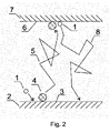
「COサイクル」は、本発明の背景内では、図1及び2に模式的に示される。 The “CO cycle” is shown schematically in FIGS. 1 and 2 within the context of the present invention.
「炭素含有前駆体材料」は、本発明の背景内では、炭素原子を含有する任意の濃縮材料(例えば、固体又は液体材料)として理解されるべきである。「炭素含有前駆体材料」は、例えば、これに限定されないが、グラファイト、大きく配向された熱分解グラファイト、スート、CNW、フラーレン、カーボンブラックを含む任意の形態で純粋な(又は実質的に純粋な)炭素;フッ化、窒化、酸化ポリマーを含む任意の種類のポリマー;又はケトン、アルコール、脂質などの室温で液状のものを含む任意の種類の炭化水素であり得る。 A "carbon-containing precursor material" is to be understood within the context of the present invention as any enriched material (eg solid or liquid material) containing carbon atoms. "Carbon-containing precursor material" is pure (or substantially pure) in any form including, but not limited to, graphite, highly oriented pyrolytic graphite, soot, CNWs, fullerenes, carbon black, ) carbon; any type of polymer, including fluorinated, nitrided, oxidized polymers; or any type of hydrocarbon, including those that are liquid at room temperature, such as ketones, alcohols, lipids, and the like.
「CxOy気体分子」は、本発明の背景内では、少なくとも2個の炭素原子(すなわち、x≧2)及び少なくとも1個の酸素原子(すなわち、y≧1)を含有する任意の分子であればよく、炭素原子数は酸素原子数よりも大きい(すなわち、x>y)。「CxOy気体分子」は、好ましくは、室温で適切な安定性を、高温で適正な不安定性を有すべきである。「CxOy気体分子」の列挙は、本発明の背景内では、これに限定されないが、C4O、C6O、C7Oを含むxが2から約1000までの任意の整数であるCxO;xが3から約1000までの任意の整数であるCxO2などの分子を含む。 A "C x O y gas molecule" within the context of the present invention is any molecule containing at least two carbon atoms (i.e. x≧2) and at least one oxygen atom (i.e. y≧1) and the number of carbon atoms is greater than the number of oxygen atoms (ie, x>y). A "C x O y gas molecule" should preferably have adequate stability at room temperature and adequate instability at elevated temperatures. The enumeration of "C x O y gas molecules" within the context of the present invention includes, but is not limited to, C 4 O, C 6 O, C 7 O, where x is any integer from 2 to about 1000. including molecules such as a C x O; C x O 2 where x is any integer from 3 to about 1000;
「基板」は、本発明の背景内では、金属及び合金、セラミック及びガラスを含む半導体、金属酸化物、金属窒化物及び金属炭化物、ポリマー並びに他の形態の炭素系材料を含む任意の固体材料であり得る。 A "substrate" within the context of the present invention is any solid material including metals and alloys, semiconductors including ceramics and glasses, metal oxides, metal nitrides and metal carbides, polymers and other forms of carbon-based materials. could be.
「CNW」材料は、本発明の背景内では、約100nmまでの厚さ、約100nmと100,000nmの間の高さを有し、基板の表面から延在する炭素含有構造体として理解されるべきである。CNW材料は、本発明の背景内では、ネットワークを形成する基板上にランダムに配向された約100nmまでの厚さの高密度構造体としても理解されるべきである。CNW材料は、本発明の背景内では、主に炭素で構成されるものとして理解されるべきであるが、水素、フッ素、窒素、酸素又は金属の原子を含む他の元素を含有してもよい。CNWの構造体は、本発明の背景内では、グラフェンに富むシートとして理解されるべきであるが、他の種類の炭素も含有し得る。そのような構造体は、滑らかな炭素材料と比べて非常に大きな表面を可能とするが、それでもグラフェンの優れた電気的及び化学的特性の利益を受ける。 A "CNW" material is understood within the context of the present invention as a carbon-containing structure extending from the surface of the substrate, having a thickness of up to about 100 nm and a height between about 100 nm and 100,000 nm. should. CNW materials should also be understood within the context of the present invention as dense structures up to about 100 nm thick randomly oriented on a substrate forming a network. CNW materials are to be understood within the context of the present invention as being composed primarily of carbon, but may contain other elements including atoms of hydrogen, fluorine, nitrogen, oxygen or metals. . The structure of CNWs should be understood within the context of the present invention as graphene-rich sheets, but may also contain other types of carbon. Such structures allow for much larger surfaces compared to smooth carbon materials, yet still benefit from the excellent electrical and chemical properties of graphene.
好適な実施形態では、CNWは、COサイクルを用いて合成される。このアプローチを用いると、固体基板の広い範囲でCNWの急速な合成が可能となり、成長速度は執筆時に本発明者に知られていた合成手順よりも優れる。 In a preferred embodiment, CNWs are synthesized using the CO cycle. Using this approach, rapid synthesis of CNWs on a wide range of solid substrates is possible, with growth rates superior to the synthetic procedures known to the inventors at the time of writing.
CNW材料は、グラフェン特性が好適であって大きな表面積対質量比が必要な場合の大量適用に対して有望である。簡単に上述した公知の技術は、標準的には1nm/秒のオーダーの低い堆積速度に阻まれていた。現技術の低い堆積速度は、CHxラジカルからの炭素の堆積に基づく合成手順に起因する。ラジカルは、気体プラズマにおいて、あるいは熱配線を用いて形成される。処理チャンバ内の圧力は、プラズマにおけるCHxラジカルの密度を制限する。圧力が高すぎると、CHxラジカルの気相凝集が起こり、基板表面で吸着する生成CxOyクラスタは、CNWの形成を可能としないが水素化炭素の薄膜の形成を可能とする。現技術の他の欠点は、CNWの成長に応じた炭素含有材料(ほとんどの技術では炭化水素)の連続供給の必要があることである。現技術のさらに他の欠点は、堆積したCNWの品質を高めるために原子形態で作用する水素が必要となることである。本発明は、CNWの優れたグラフェン状構造を失うことなく成長速度を実質的に増加させることによって現技術のそれら短所に対処する。成長速度は炭素源としてCxOy気体分子を用いて高められ、合成手順は、反応チャンバへの前駆体の連続供給を与えることを要さずに、大幅に制御可能となる。またさらに、発明の方法では、水素は用いられない。 CNW materials are promising for high-volume applications where graphene properties are favorable and a large surface-to-mass ratio is required. Known techniques, briefly mentioned above, have been hampered by low deposition rates, typically on the order of 1 nm/sec. The low deposition rate of the current technology is due to synthetic procedures based on the deposition of carbon from CH x radicals. Radicals are formed in a gas plasma or using a hot wire. The pressure in the process chamber limits the density of CHx radicals in the plasma. If the pressure is too high, vapor phase condensation of CH x radicals will occur and the resulting C x O y clusters that adsorb on the substrate surface will not allow the formation of CNWs but will allow the formation of thin films of hydrogenated carbon. Another drawback of the current technology is the need for a continuous supply of carbon-containing materials (hydrocarbons in most technologies) as the CNW grows. Yet another drawback of the current technology is the need for hydrogen acting in atomic form to enhance the quality of the deposited CNWs. The present invention addresses those shortcomings of the current technology by substantially increasing the growth rate without losing the excellent graphene-like structure of CNWs. The growth rate is enhanced using C x O y gaseous molecules as the carbon source and the synthesis procedure becomes greatly controllable without the need to provide a continuous supply of precursors to the reaction chamber. Furthermore, in the method of the invention, hydrogen is not used.
発明の方法では、CxOy気体分子が、CNWの構成材料として適用される。CxOy気体分子は、文献ではほとんど言及されない。C及びOのみを含有する一般に知られている気体分子は、一酸化炭素(CO)、二酸化炭素(CO2)、二酸化三炭素(C3O2)及び二酸化五炭素(C5O2)である。これらの分子は、室温で気体であるが、炭素原子数が3より大きい場合には本来的に不安定である。グラフェン酸化物は、他のタイプのCxOy気体分子である。これらは、酸素原子によって終端され(エポキシ結合であることが多い)又はOHラジカルによって終端された幾つかの六角形炭素環を含有し得る。グラフェン酸化物は、室温で固体であり、非常に安定的である。非平衡条件下で、酸素を炭素含有材料と相互作用させると、様々なCxOy気体分子が生成される。 In the method of the invention, CxOy gas molecules are applied as building blocks of CNWs . CxOy gas molecules are rarely mentioned in the literature. Commonly known gas molecules containing only C and O are carbon monoxide ( CO), carbon dioxide ( CO2 ), tricarbon dioxide ( C3O2 ) and pentacarbon dioxide ( C5O2 ). be. These molecules are gases at room temperature, but are inherently unstable when the number of carbon atoms is greater than 3. Graphene oxide is another type of C x O y gas molecule. They may contain several hexagonal carbocycles terminated by oxygen atoms (often epoxy bonds) or by OH radicals. Graphene oxide is solid at room temperature and very stable. Under non-equilibrium conditions, the interaction of oxygen with carbon-containing materials produces various C x O y gas molecules.
多くのCxOy気体分子は、不安定であり、自発的に分解する。分解速度は、温度に依存する。一般則として、分解速度は、温度の増加とともに増加する。多くのCxOy気体分子は、室温では低速分解するが、高温では非常に速く分解する。本発明の好適な実施形態は、CxOy気体分子の分解速度の温度依存性を利用する。好適な実施形態では、反応チャンバ全体は、反応チャンバの壁面又は反応チャンバの他の部分における熱分解によるCxOy気体分子の実質的な喪失を防止するために、室温に又は室温よりもわずかに高く維持される。一方、基板は、その表面でのCxOy気体分子の急速な熱分解を促進するために、好ましくはより高い温度に維持される。 Many C x O y gas molecules are unstable and spontaneously decompose. The decomposition rate is temperature dependent. As a general rule, the decomposition rate increases with increasing temperature. Many CxOy gas molecules decompose slowly at room temperature, but very rapidly at elevated temperatures. A preferred embodiment of the present invention exploits the temperature dependence of the decomposition rate of CxOy gas molecules. In a preferred embodiment, the entire reaction chamber is at or slightly below room temperature to prevent substantial loss of CxOy gas molecules due to thermal decomposition on the walls of the reaction chamber or other portions of the reaction chamber. maintained high at Meanwhile, the substrate is preferably maintained at a higher temperature to promote rapid thermal decomposition of the CxOy gas molecules at its surface.
炭素含有気体分子のそれ自体による熱分解は、基板表面での炭素原子の必要なCNW配置を必ずしも確実にしない。理解されるように、炭素は、通常はCNW以外の多数の形態で成長する。CNWは、プラスに帯電したCxOy気体分子の基板との同時相互作用に起因して優先的に成長するものと考えられる。プラスに帯電したイオンは、気体プラズマと基板の間のシースで加速され、基板と相互作用する直前に10eVのオーダーのエネルギーを得る。このエネルギーは、基板上の炭素原子の適正な配置を可能とするので有益であり、上記炭素原子はCNWの形態で配列する。 Thermal decomposition of carbon-containing gas molecules by itself does not necessarily ensure the required CNW arrangement of carbon atoms at the substrate surface. As will be appreciated, carbon typically grows in many forms other than CNWs. CNWs are believed to grow preferentially due to the simultaneous interaction of positively charged C x O y gas molecules with the substrate. Positively charged ions are accelerated in the sheath between the gas plasma and the substrate and acquire energies on the order of 10 eV just before interacting with the substrate. This energy is beneficial because it allows proper placement of the carbon atoms on the substrate, said carbon atoms arranging in the form of CNWs.
方法は、反応チャンバに配置された炭素含有前駆体材料のアブレーションの工程を含み得る。炭素含有前駆体材料のアブレーション速度は、材料の温度に依存する。好適な実施形態では、炭素含有前駆体材料は、炭素含有前駆体材料の急速なアブレーションを確実にするために、非常に高温に加熱される。炭素含有前駆体材料は、好適な実施形態では、反応性プラズマ種によって、特に、上記炭素含有前駆体材料とのCO分子の相互作用によってアブレーションされる。CO分子は、中性とされ又はプラスに帯電され得る。気体プラズマにおける中性のCO分子は、振動的に励起されるようになり、それにより炭素含有材料のアブレーション速度を増加させる。炭素含有材料のアブレーションは、好適な実施形態によると、上記炭素含有材料の表面でのCxOy気体分子の形成をもたらし、上記CxOy気体分子は上記炭素含有材料の表面から脱着される。 The method may include ablation of a carbon-containing precursor material located in the reaction chamber. The ablation rate of carbon-containing precursor materials depends on the temperature of the material. In a preferred embodiment, the carbon-containing precursor material is heated to very high temperatures to ensure rapid ablation of the carbon-containing precursor material. The carbon-containing precursor material is in a preferred embodiment ablated by reactive plasma species, in particular by interaction of CO molecules with said carbon-containing precursor material. CO molecules can be neutral or positively charged. Neutral CO molecules in the gas plasma become vibrationally excited, thereby increasing the ablation rate of carbon-containing materials. Ablation of a carbon-containing material, according to a preferred embodiment, results in the formation of CxOy gas molecules at the surface of said carbon-containing material, said CxOy gas molecules being desorbed from the surface of said carbon-containing material. be.
本発明によるCOサイクルに影響を与えると考えられる他のパラメータは、ガス純度である。理論に拘束されることを望まないが、存在する場合には酸素含有以外のガスも同様に、酸素含有ガスへの曝露に応じて炭素含有前駆体材料と、例えばその表面で反応するものと想定される。したがって、好適な実施形態では、酸素含有ガスは、反応ガスにおいて比較的高いレベルの純度、例えば、90%、95%、99%又は99%のモル濃度の酸素含有ガスで炭素含有材料と接触している。この目的のため、処理チャンバは、他の気体を反応チャンバから除去するために、まず比較的低い圧力に脱気されてから、酸素含有ガスのみがチャンバに付加される。したがって、処理チャンバは、まず適切な真空ポンプによって脱気される。脱気後の処理チャンバ内の圧力は、好ましくは10Pa以下であり、さらにより好ましくは1Pa以下である。脱気が成功した後、処理チャンバは、例えば1000Pa、100Pa又は10Paの(より高い)圧力まで酸素含有ガスで充填される。これは、大気圧よりも低い。そのような適度な圧力は、酸素含有ガスと炭素含有材料の間の親和性の観点で有利なことが分かった。したがって、真空チャンバの使用は、COサイクルを適切に利用するために、酸素含有ガスの高い純度を確実にし、適切な圧力を確実にするのに有利である。 Another parameter that is believed to affect the CO cycle according to the invention is gas purity. While not wishing to be bound by theory, it is assumed that non-oxygen-containing gases, if present, will also react with the carbon-containing precursor material, e.g., at its surface, upon exposure to the oxygen-containing gas. be done. Thus, in preferred embodiments, the oxygen-containing gas is contacted with the carbon-containing material at a relatively high level of purity in the reactant gas, e.g., 90%, 95%, 99% or 99% molar oxygen-containing gas. ing. For this purpose, the processing chamber is first evacuated to a relatively low pressure to remove other gases from the reaction chamber, and then only oxygen-containing gas is added to the chamber. Therefore, the processing chamber is first evacuated by a suitable vacuum pump. The pressure in the processing chamber after degassing is preferably 10 Pa or less, and even more preferably 1 Pa or less. After successful degassing, the process chamber is filled with an oxygen-containing gas to a (higher) pressure of eg 1000Pa, 100Pa or 10Pa. This is below atmospheric pressure. Such moderate pressure has been found to be advantageous in terms of affinity between the oxygen-containing gas and the carbon-containing material. The use of a vacuum chamber is therefore advantageous to ensure high purity of the oxygen-containing gas and to ensure adequate pressure for proper utilization of the CO cycle.
処理の最適な継続時間は、炭素含有材料及び基板の双方の温度、(放電パラメータに同様に依存する)プラズマパラメータ並びに酸素含有ガスの圧力のような処理パラメータに依存する。 The optimum duration of treatment depends on process parameters such as the temperature of both the carbon-containing material and the substrate, the plasma parameters (which also depend on the discharge parameters) and the pressure of the oxygen-containing gas.
CNW堆積速度は、炭素含有前駆体材料の温度の上昇とともに増加する。約300℃の炭素含有前駆体材料において、満足なアブレーション速度が達成される。炭素含有前駆体材料の温度の更なる上昇は、より高いアブレーション速度をもたらす。より高いアブレーション速度は、同様に、CNW堆積速度の増加をもたらす。ある実験では、炭素含有材料の温度が約800℃であり、約100nm/秒の堆積速度が達成された。 The CNW deposition rate increases with increasing temperature of the carbon-containing precursor material. Satisfactory ablation rates are achieved for carbon-containing precursor materials at about 300°C. Further increases in the temperature of the carbon-containing precursor material result in higher ablation rates. Higher ablation rates also lead to increased CNW deposition rates. In one experiment, the temperature of the carbon-containing material was about 800° C. and a deposition rate of about 100 nm/sec was achieved.
基板の温度は、役割を果たす。基板の温度が約100℃であって温度の上昇とともに増加する場合に、基板上のCNWの堆積速度は低いことが分かる。約400℃の基板温度において、より高いCNW堆積速度が達成可能である。基板温度の更なる上昇は、増加するCNW堆積速度をもたらす。ある実験では、基板の温度は約1000℃であり、約100nm/秒の堆積速度が達成された。 Substrate temperature plays a role. It can be seen that the deposition rate of CNW on the substrate is low when the temperature of the substrate is about 100° C. and increases with increasing temperature. At substrate temperatures of about 400° C., higher CNW deposition rates are achievable. Further increases in substrate temperature result in increased CNW deposition rates. In one experiment, the substrate temperature was about 1000° C. and a deposition rate of about 100 nm/sec was achieved.
好適な実施形態では、酸素含有ガスの圧力は、1Paと100Paの間である。この範囲での動作は、種々の電気放電による反応チャンバにおけるプラズマの確実な点火及び維持を可能とする。好適な実施形態では、プラズマは、高周波無電極放電によって維持される。適切な周波数は、0.1MHzと10GHzの間である。プラズマに面する材料のスパッタリングが抑制されるので、そのような無電極結合は有益である。好ましくは、放電は、無線周波数(13.56MHz、27.12MHz、又は13.56MHzの他の任意の高調波)又はマイクロ波周波数(例えば、2.45GHz)で動作する標準的な高周波発生器によって電力供給される。放電発生器の電力は、処理チャンバにおける気体プラズマを維持するのに充分高いものであるべきである。発生器電力の適切な範囲は、反応チャンバの体積及び酸素含有ガスの圧力に依存する。標準的には、より大きな体積及びより高い圧力は、より高い放電電力を必要とする。ある実験では、酸素含有ガスの圧力は30Paであり、高密度プラズマの体積は約1リットルであり、放電電力は800Wであった。 In a preferred embodiment, the pressure of the oxygen-containing gas is between 1Pa and 100Pa. Operation in this range allows reliable ignition and maintenance of a plasma in the reaction chamber by various electrical discharges. In a preferred embodiment the plasma is maintained by a high frequency electrodeless discharge. Suitable frequencies are between 0.1 MHz and 10 GHz. Such electrodeless bonding is beneficial because sputtering of material facing the plasma is suppressed. Preferably, the discharge is by a standard radio frequency generator operating at radio frequency (13.56 MHz, 27.12 MHz, or any other harmonic of 13.56 MHz) or microwave frequency (e.g. 2.45 GHz). Powered. The electrical discharge generator power should be high enough to sustain the gas plasma in the processing chamber. A suitable range of generator power depends on the volume of the reaction chamber and the pressure of the oxygen-containing gas. Typically, larger volumes and higher pressures require higher discharge power. In one experiment, the oxygen-containing gas pressure was 30 Pa, the high-density plasma volume was about 1 liter, and the discharge power was 800W.
好ましくは、加熱された基板とCxOy気体分子との接触時間は、0.1sと1000sの間である。更なる好適な実施形態では、処理時間は、1sと100sの間である。この好適な処理時間は、本発明による、炭素含有材料の好適な圧力及び好適な温度並びに基板の好適な温度において最適なCNWの堆積効率を可能とする。好ましくは、処理中の基板の温度は、700℃と1000℃の間である。より低い温度では、最適なCNW堆積に要する処理時間が長くなりすぎ、より高い温度では、CNWの所望の特性が失われ得るほどにCNWが劣化してしまうことになる。これは、約1500℃以上の温度で、又は他の形態的若しくは構造的形態での炭素の堆積が観察される2000℃でも、特に当てはまる。 Preferably, the contact time between the heated substrate and the CxOy gas molecules is between 0.1s and 1000s. In a further preferred embodiment the treatment time is between 1 s and 100 s. This preferred treatment time allows for optimum CNW deposition efficiency at the preferred pressure and preferred temperature of the carbon-containing material and the preferred temperature of the substrate according to the present invention. Preferably, the temperature of the substrate during processing is between 700°C and 1000°C. Lower temperatures would require too long a process time for optimal CNW deposition, and higher temperatures would degrade the CNWs to such an extent that the desired properties of the CNWs could be lost. This is especially true at temperatures above about 1500° C., or even 2000° C. where deposition of carbon in other morphological or structural forms is observed.
以下の処理パラメータ:圧力30Pa、放電電力800W、発生器周波数13.56MHz、炭素含有前駆体材料の温度800℃、基板温度1000℃及び強度の気体プラズマの体積1リットルは、特に有利であることを示した。 The following process parameters: pressure of 30 Pa, discharge power of 800 W, generator frequency of 13.56 MHz, temperature of the carbon-containing precursor material of 800° C., substrate temperature of 1000° C. and volume of gaseous plasma of 1 liter intensity have been found to be particularly advantageous. Indicated.
ここで、本発明のいくつかの好適な実施形態を、以下の非限定的な実施例を参照して説明する。 Some preferred embodiments of the invention will now be described with reference to the following non-limiting examples.
CNWを、図1及び2に模式的に示す処理に従ってチタン基板上に堆積させた。約1000℃まで加熱された(チタン)基板を酸素含有ガス(この場合、純粋な二酸化炭素)に接触させた圧力は30Paであり、放電発生器の周波数は13.56MHzであり、炭素含有材料の温度は800℃であった。処理時間は20sであった。 CNWs were deposited on titanium substrates according to the process schematically illustrated in FIGS. The pressure at which the (titanium) substrate heated to about 1000° C. was brought into contact with the oxygen-containing gas (pure carbon dioxide in this case) was 30 Pa, the discharge generator frequency was 13.56 MHz, and the carbon-containing material The temperature was 800°C. Processing time was 20 s.
チタン基板上に堆積したCNWを走査型電子顕微鏡(SEM)で撮影した。図3は、標準的な製品のSEM画像を示す。堆積したCNWコーティングは、超疎水性特性を有する。CNWコーティングの表面上の水滴の画像を図4に示す。 The CNWs deposited on the titanium substrate were photographed with a scanning electron microscope (SEM). FIG. 3 shows an SEM image of a standard product. The deposited CNW coating has superhydrophobic properties. An image of water droplets on the surface of the CNW coating is shown in FIG.
本実施例のための実験の設定を図5に模式的に示す。反応チャンバ9は、ホウケイ酸ガラスからなり、2段階回転真空ポンプ10が装備される。真空ポンプ10を反応チャンバ9から切り離すためのゲートバルブ11がある。酸素含有ガスは、リークバルブ13で反応チャンバ9から切り離された高圧容器12に保存された二酸化炭素であった。気体プラズマは、周波数13.56MHz及び出力電力800Wで動作する無線周波発生器14によって反応チャンバ内に生成される。発生器は、気体プラズマにアンテナ15を介して結合される。炭素含有前駆体材料、この場合では一片のグラファイト16、及びサンプル17を同じ反応チャンバ9内に相互に隣接させて配置した。
The experimental set-up for this example is shown schematically in FIG. The
まず、反応チャンバ9を真空ポンプ10によって1Pa以下の圧力まで脱気した。その後、ポンプを、ゲートバルブ11を閉じることによって反応チャンバ9から切り離した。反応チャンバ9において圧力30Paに達するまで、高圧容器12からの二酸化炭素を脱気後の反応チャンバ9にリークバルブ13を用いてリークさせた。圧力30Paに達すると、リークバルブを閉じた。その後、RF発生器14を用いてプラズマを反応チャンバ9内部で生成した。グラファイトブロック16及びサンプル17の双方をRF発生器14によるプラズマへの電力拡散によって反応チャンバ9の内部で加熱したので、この実施例1では外部加熱を行わなかった。プラスに帯電したイオンの密度は、1018m-3のオーダーであった。
First, the
この実施例での処理時間を変化させ、CNWの厚さを各処理時間について測定した。処理時間に対するCNWの厚さを図6に示す。 The treatment time in this example was varied and the CNW thickness was measured for each treatment time. FIG. 6 shows the CNW thickness versus treatment time.
実施例2は、CxOy気体分子の合成に適した構成を開示する。炭素含有前駆体材料及び加熱された基板の気体プラズマへの独立した曝露を可能とするために、図5に示す設定を修正した。全体として、実験の設定は、反応チャンバ9の配置以外は、実施例1に対する図5のものと同様である。実施例2で用いた反応チャンバ9を図7に模式的に示す。反応チャンバ9には、いくつかのダクトが装備されている。ダクト18は、反応チャンバ9をポンピングするために用いられる。ダクト19は、酸素含有ガスを反応チャンバ9にリークさせるために用いられる。ダクト20は、炭素含有前駆体材料21を有するホルダを反応チャンバ9内に配置するために用いられる。炭素含有前駆体材料21を有するホルダは可動であるので、ダクト20内又は反応チャンバ内部(図7の破線位置)のいずれかに配置される。炭素含有前駆体材料21を有するホルダは、これに限定されないが、抵抗加熱、誘導加熱又は光子、電子若しくはイオンの照射を含む任意の適宜の方法を用いて外部加熱され得る。
Example 2 discloses a configuration suitable for the synthesis of CxOy gas molecules. The setup shown in FIG. 5 was modified to allow independent exposure of the carbon-containing precursor material and the heated substrate to the gas plasma. Overall, the experimental setup is similar to that of FIG. 5 for Example 1, except for the placement of the
炭素含有前駆体材料21を有するホルダは、ダクト20内部の位置に搭載された。まず、反応チャンバ9を真空ポンプ10によって1Pa以下の圧力まで脱気した。その後、ポンプを、ゲートバルブ11を閉じることによって反応チャンバ9から切り離した。反応チャンバ9において圧力30Paに達するまで、高圧容器12からの二酸化炭素を脱気後の反応チャンバ9にリークバルブ13を用いてリークさせた。圧力30Paに達すると、リークバルブ13を閉じた。その後、RF発生器14を用いてプラズマを反応チャンバ9内部で生成した。炭素含有材料21を有するホルダをダクト20内部の位置から反応チャンバ9の中心まで移動させた。反応チャンバ9の中心における炭素含有材料21を有するホルダの位置を図7では破線で印す。反応チャンバ9の内部のプラズマは、光学分光法によって特徴付けられた。反応チャンバ内のプラズマのスペクトルでは、炭素含有材料21を有するホルダがダクト20の位置に搭載される限りは原子の酸素のスペクトル線が優勢であった。炭素含有材料21を有するホルダがダクト20内部の位置に搭載される限り、777nmにおける酸素のスペクトル線とC2帯域の最も強いスペクトル線の比は約7であった。炭素含有材料21を有するホルダをダクト20内部の位置から反応チャンバ9の中心-図7の破線位置-へ移動させると、777nmにおける酸素のスペクトル線とC2帯域の最も強いスペクトル線の比は1秒以内に0.5に低下し、安定的なCxOy気体分子への酸素の結合を示した。したがって、実施例2に開示される方法によって安定的なCxOy気体分子の合成が可能となり、これはCNWの成長に有益であると考えられる。
A holder with carbon-containing
実施例3は、CxOy気体分子からのCNWの合成に適した構成を開示する。炭素含有材料及び加熱された基板の気体プラズマへの独立した曝露を可能とするために、図5に模式的に示す設定を修正した。実施例3に有用な反応チャンバ9を、関連する詳細について図7に模式的に示す。反応チャンバ9には、いくつかのダクトが装備されている。ダクト18は、反応チャンバ9をポンピングするために用いられる。ダクト19は、酸素含有ガスを反応チャンバ9にリークさせるために用いられる。ダクト20は、炭素含有材料21を有するホルダを反応チャンバ9内に配置するために用いられる。ダクト22は、基板23を有するホルダを反応チャンバ9内に配置するために用いられる。基板23を有するホルダは可動であるので、ダクト22内又は反応チャンバ内部(図7の破線位置)のいずれかに配置される。基板23を有するホルダは、これに限定されないが、抵抗加熱、誘導加熱又は光子、電子若しくはイオンの照射を含む任意の方法を用いて外部加熱され得る。
Example 3 discloses a configuration suitable for the synthesis of CNWs from C x O y gas molecules. The setup shown schematically in FIG. 5 was modified to allow independent exposure of the carbon-containing material and the heated substrate to the gas plasma. A
基板23を有するホルダをダクト22の位置に搭載した。CxOy気体分子を実施例2に開示される手順に従って合成した。CxOy気体分子が反応チャンバにおいて生成されると、放電をオフし、炭素含有材料21を有するホルダをダクト20の内部の位置に移動させた。そのような放電をオフした状態の構成を数分にわたって維持した。その後、基板23を有するホルダを、図7に示すような反応チャンバ9の内部の破線位置に移動させ、放電をオンした。放電がオンされ、図7の破線位置において基板23を有するホルダが500℃の高温まで加熱されるとすぐに、CNWが、実施例1と同様に、基板23を有するホルダ上で約100nm/秒の成長速度で成長を開始した。
A holder with a
それらの具体的形態で又は開示される機能を実行するための手段、又は開示される結果を得るための方法若しくは処理の観点で表現された以上の説明、以下の特許請求の範囲又は添付図面において開示した特徴は、別個に又はその特徴のいずれかの組合せにおいて、その多様な形態において本発明を実現するのに適宜利用され得る。 In the foregoing description, the following claims or the accompanying drawings expressed in terms of their specific forms or in terms of means for performing the functions disclosed, or methods or processes for achieving the results disclosed The disclosed features may be used individually or in any combination of features as appropriate to implement the invention in its various forms.
本発明を上述の例示的実施形態との関連で説明したが、本開示が与えられれば、当業者には多数の均等な変形例及びバリエーションが明らかとなるはずである。したがって、以上の本発明の例示的実施形態は、限定ではなく例示とみなされるべきである。記載した実施形態に対する種々の変更が、本発明の主旨及び範囲から離れることなくなされ得る。 Although the invention has been described in conjunction with the exemplary embodiments described above, many equivalent modifications and variations should become apparent to those skilled in the art given this disclosure. Accordingly, the exemplary embodiments of the present invention as set forth above are to be considered illustrative rather than limiting. Various changes to the described embodiments may be made without departing from the spirit and scope of the invention.
疑義を回避するため、ここに与えられるいずれの理論的説明は、読者の理解を向上する目的で与えられるものである。発明者は、これらの理論的説明のいずれかに拘束されることを望まない。 For the avoidance of doubt, any theoretical explanation given herein is given for the purpose of enhancing the reader's understanding. The inventors do not wish to be bound by any of these theoretical explanations.
ここに使用されるいずれの見出しも、整理のみを目的とするものであり、記載される主題を限定するものとして解釈されてはならない。 Any headings used herein are for organizational purposes only and should not be construed as limiting the subject matter described.
以降の特許請求の範囲を含み、本明細書の全体を通じて、文脈がそれ以外を要件としない限り、文言「備える」及び「含む」、並びに「備える」、「備えている」及び「含んでいる」などの変化形は、記載される完全体若しくは工程又は完全体若しくは工程の群の包含を意味するものであるが、他のいずれかの完全体若しくは工程又は完全体若しくは工程の群の除外を意味するものではないことが理解されるはずである。 Throughout this specification, including the claims that follow, unless the context requires otherwise, the words "comprising" and "including" and "comprising", "comprising" and "including" is meant to include the recited integer or step or group of integers or steps, but exclude any other integer or step or group of integers or steps. It should be understood that it is not implied.
本願及び添付の特許請求の範囲において使用される単数形「a」、「an」及び「the」は、明らかにそれ以外を述べていない限りは複数形のものを含むことが留意されるべきである。範囲は、「約」一方の特定値から及び/又は「約」他方の特定値までとしてここでは表現され得る。そのような範囲が表現された場合には、他の実施形態は、その一方の特定値から及び/又は他方の特定値までを含む。同様に、先行する「約」の使用によって値が概数として表現される場合、特定値が他の実施形態を形成することが理解されるはずである。数値との関係での文言「約」は、選択的であり、例えば±10%を意味する。 It should be noted that the singular forms "a," "an," and "the," as used in this application and the appended claims, include plural forms unless clearly stated otherwise. be. Ranges can be expressed herein as from "about" one particular value, and/or to "about" the other particular value. When such a range is expressed, another embodiment includes from the one particular value and/or to the other particular value. Similarly, when a value is expressed as an approximation by the use of the antecedent "about," it should be understood that the particular value forms another embodiment. The word "about" in relation to numerical values is optional and means ±10%, for example.
参照文献
本発明及び本発明が関連する現状の技術をより完全に説明及び開示するために、多数の刊行物が上記で引用されている。これらの参照文献についての全引用を以下に与える。これらの参照文献の各々の全体がここに取り込まれる。
Y.Wu、P.Qiao、T.Chong and Z.Shen、Carbon nanowalls grown by microwave plasma enhanced chemical vapor deposition、Advanced Materials vol.14、No.1(2002)
BJ Yang et al.、Nano Letters Vol.2 Iss.7、p.751-754(2002)
K.Shiji et al、Diamond and Related Materials Vol.14 Iss.3-7、p.831-834(2005)
K.Tanaka et al.、Japanese Journal of Applied Physics Vol.44 Iss.4A、p.2074-2076(2005)
Itoh et al、Thin Solid Films Vol.501 Iss.1-2、p.314-317(2006)
Dikonimos et al.、Diamond and Related Materials Iss.4-7 p.1240-1243(2007)
S.Shimabukuro et al.、Effect of hydrogen dilution in preparation of CNW by hot-wire CVD、Thin Solid Films Vol.516 Iss.5 p.710-713(2008)
米国特許出願公開第2007/184190号明細書
特開第2008-063196号
米国特許出願公開第2011/045207号明細書
米国特許出願公開第2009/274610号明細書
中国特許出願公開第103420354号明細書
国際公開第2016/024301号パンフレット
米国特許出願公開第2011/0033367号明細書
韓国特許出願公開第200631291号明細書
特開第2008-239369号
米国特許出願公開第2008/274392号明細書
特開第2010-009980号
特開第2010-009980号
中国特許出願公開第102668180号明細書
米国特許出願公開第2014/170490号明細書
台湾特許出願公開第2014-48327号明細書
中国特許出願公開第102668181号明細書
米国特許出願公開第2010/212728号明細書
米国特許出願公開第2012/175515号明細書
特開第2015-118348号
国際公開第2016/059024パンフレット
中国特許出願公開第103935975号明細書
中国特許出願公開第103935982号明細書
中国特許出願公開第103935983号明細書
米国特許出願公開第2014/127411号明細書
REFERENCES A number of publications are cited above in order to more fully describe and disclose the invention and the state of the art to which the invention pertains. Full citations for these references are given below. The entirety of each of these references is incorporated herein.
Y. Wu, P. Qiao, T. Chong and Z.W. Shen, Carbon nanowalls grown by microwave plasma enhanced chemical vapor deposition, Advanced Materials vol. 14, No. 1 (2002)
BJ Yang et al. , Nano Letters Vol. 2 Iss. 7, p. 751-754 (2002)
K. Shiji et al, Diamond and Related Materials Vol. 14 Iss. 3-7, p. 831-834 (2005)
K. Tanaka et al. , Japanese Journal of Applied Physics Vol. 44 Iss. 4A, p. 2074-2076 (2005)
Itoh et al., Thin Solid Films Vol. 501 Iss. 1-2, p. 314-317 (2006)
Dikonimos et al. , Diamond and Related Materials Iss. 4-7 p. 1240-1243 (2007)
S. Shimabukuro et al. , Effect of hydrogen dilution in preparation of CNW by hot-wire CVD, Thin Solid Films Vol. 516 Iss. 5 p. 710-713 (2008)
US Patent Application Publication No. 2007/184190 JP 2008-063196 US Patent Application Publication No. 2011/045207 US Patent Application Publication No. 2009/274610 China Patent Application Publication No. 103420354 International Publication No. 2016/024301 Pamphlet US Patent Application Publication No. 2011/0033367 Korean Patent Application Publication No. 200631291 JP 2008-239369 US Patent Application Publication No. 2008/274392 JP 2010- 009980 JP 2010-009980 Chinese Patent Application Publication No. 102668180 US Patent Application Publication No. 2014/170490 Taiwan Patent Application Publication No. 2014-48327 Chinese Patent Application Publication No. 102668181 United States Patent Application Publication No. 2010/212728 US Patent Application Publication No. 2012/175515 Japanese Patent Application Publication No. 2015-118348 International Publication No. 2016/059024 Pamphlet China Patent Application Publication No. 103935975 China Patent Application Publication No. 103935982 No. Chinese Patent Application Publication No. 103935983 US Patent Application Publication No. 2014/127411
Claims (16)
固体又は液体材料である炭素含有前駆体材料を反応チャンバに供給する工程と、
酸素含有雰囲気を前記反応チャンバに供給する工程と、
前記反応チャンバ内で前記酸素含有雰囲気においてプラズマ放電を形成する工程と、
を備え、
前記プラズマ放電におけるCO分子が前記炭素含有前駆体材料と相互作用してx>yであるCxOy分子を形成し、該CxOy分子が前記基板に拡散して前記基板において分解してCO分子及び炭素を形成し、該炭素がCNWを形成する、方法。 A method of depositing a layer of CNWs on a substrate using a CO cycle, comprising:
providing a carbon-containing precursor material, which is a solid or liquid material, to the reaction chamber;
providing an oxygen-containing atmosphere to the reaction chamber;
forming a plasma discharge in the oxygen-containing atmosphere within the reaction chamber;
with
CO molecules in the plasma discharge interact with the carbon-containing precursor material to form C x O y molecules where x>y, which C x O y molecules diffuse to and decompose at the substrate. to form CO molecules and carbon, the carbon forming CNWs.
請求項1から13のいずれか一項に記載の方法によって取得され又は取得可能であるCNW材料の製造方法。 A method of manufacturing a CNW material, the method comprising:
14. A method for producing a CNW material obtained or obtainable by the method of any one of claims 1-13.
請求項14に記載のCNW材料の製造方法。 wherein the CNW material is used in a fuel cell or photovoltaic device;
A method for producing a CNW material according to claim 14.
x>yであるCxOy分子を含有する雰囲気を反応チャンバに供給する工程と、
基板を前記反応チャンバに供給する工程と、
前記反応チャンバ内で前記x>yであるCxOy分子を含有する雰囲気においてプラズマ放電を形成する工程と、
を備え、
前記x>yであるCxOy分子が前記基板に拡散し、前記基板において分解してCO分子及び炭素を形成し、該炭素がCNWを形成する、方法。
A method of depositing a layer of CNWs on a substrate, comprising:
providing an atmosphere containing C x O y molecules where x>y to the reaction chamber;
providing a substrate to the reaction chamber;
forming a plasma discharge in the reaction chamber in an atmosphere containing C x O y molecules where x>y;
with
The method wherein the C x O y molecules with x>y diffuse into the substrate and decompose at the substrate to form CO molecules and carbon, which carbon forms CNWs.
Applications Claiming Priority (1)
| Application Number | Priority Date | Filing Date | Title |
|---|---|---|---|
| PCT/EP2018/065365 WO2019238206A1 (en) | 2018-06-11 | 2018-06-11 | Carbon nanostructured materials and methods for forming carbon nanostructured materials |
Publications (2)
| Publication Number | Publication Date |
|---|---|
| JP2021528346A JP2021528346A (en) | 2021-10-21 |
| JP7156648B2 true JP7156648B2 (en) | 2022-10-19 |
Family
ID=62683180
Family Applications (1)
| Application Number | Title | Priority Date | Filing Date |
|---|---|---|---|
| JP2020568541A Active JP7156648B2 (en) | 2018-06-11 | 2018-06-11 | Carbon nanostructured material and method of forming carbon nanostructured material |
Country Status (5)
| Country | Link |
|---|---|
| US (1) | US11673807B2 (en) |
| EP (1) | EP3802418B1 (en) |
| JP (1) | JP7156648B2 (en) |
| SI (1) | SI25662A (en) |
| WO (1) | WO2019238206A1 (en) |
Families Citing this family (19)
| Publication number | Priority date | Publication date | Assignee | Title |
|---|---|---|---|---|
| ES2964898T3 (en) | 2015-12-16 | 2024-04-10 | 6K Inc | Spheroidal dehydrogenated metals and metal alloy particles |
| US10987735B2 (en) | 2015-12-16 | 2021-04-27 | 6K Inc. | Spheroidal titanium metallic powders with custom microstructures |
| EP3810358A1 (en) | 2018-06-19 | 2021-04-28 | 6K Inc. | Process for producing spheroidized powder from feedstock materials |
| CN114007782A (en) | 2019-04-30 | 2022-02-01 | 6K有限公司 | Mechanically alloyed powder feedstock |
| ES2994209T3 (en) | 2019-11-18 | 2025-01-20 | 6K Inc | Unique feedstocks for spherical powders and methods of manufacturing |
| WO2021115596A1 (en) * | 2019-12-11 | 2021-06-17 | Jozef Stefan Institute | Method and apparatus for deposition of carbon nanostructures |
| US11590568B2 (en) | 2019-12-19 | 2023-02-28 | 6K Inc. | Process for producing spheroidized powder from feedstock materials |
| KR20230029836A (en) | 2020-06-25 | 2023-03-03 | 6케이 인크. | Microcomposite alloy structure |
| KR102811425B1 (en) | 2020-09-24 | 2025-05-26 | 6케이 인크. | Systems, devices and methods for initiating plasma |
| WO2022094528A1 (en) | 2020-10-30 | 2022-05-05 | 6K Inc. | Systems and methods for synthesis of spheroidized metal powders |
| US12312679B2 (en) * | 2020-12-22 | 2025-05-27 | Joz̃Stefan Institute | Method for producing N-doped carbon nanomesh |
| AU2022206483A1 (en) | 2021-01-11 | 2023-08-31 | 6K Inc. | Methods and systems for reclamation of li-ion cathode materials using microwave plasma processing |
| EP4313449A1 (en) | 2021-03-31 | 2024-02-07 | 6K Inc. | Systems and methods for additive manufacturing of metal nitride ceramics |
| CN113860285A (en) * | 2021-10-27 | 2021-12-31 | 燕山大学 | Nano-diamond structure carbon material prepared massively at normal pressure and preparation method and application thereof |
| US12261023B2 (en) | 2022-05-23 | 2025-03-25 | 6K Inc. | Microwave plasma apparatus and methods for processing materials using an interior liner |
| US12040162B2 (en) | 2022-06-09 | 2024-07-16 | 6K Inc. | Plasma apparatus and methods for processing feed material utilizing an upstream swirl module and composite gas flows |
| WO2024044498A1 (en) | 2022-08-25 | 2024-02-29 | 6K Inc. | Plasma apparatus and methods for processing feed material utilizing a powder ingress preventor (pip) |
| US12195338B2 (en) | 2022-12-15 | 2025-01-14 | 6K Inc. | Systems, methods, and device for pyrolysis of methane in a microwave plasma for hydrogen and structured carbon powder production |
| JP7742058B2 (en) * | 2023-04-21 | 2025-09-19 | 国立大学法人東海国立大学機構 | ELECTRODE FOR ELECTRIC STORAGE DEVICE, SECONDARY BATTERY, AND METHOD FOR MANUFACTURING ELECTRIC STORAGE DEVICE ELECTRODE |
Citations (3)
| Publication number | Priority date | Publication date | Assignee | Title |
|---|---|---|---|---|
| WO2008117777A1 (en) | 2007-03-25 | 2008-10-02 | Nu Eco Engineering Co. Ltd. | Method for producing carbon nanowall |
| JP2011038797A (en) | 2009-08-06 | 2011-02-24 | Nagoya Univ | Sample substrate for laser eliminated ionization mass analysis, and method and device for analyzing laser eliminated ionization mass using the same |
| WO2019035438A1 (en) | 2017-08-15 | 2019-02-21 | 住友電気工業株式会社 | Body obtained by processing solid carbon-containing material, producing method thereof and producing apparatus thereof |
Family Cites Families (23)
| Publication number | Priority date | Publication date | Assignee | Title |
|---|---|---|---|---|
| JP3962420B2 (en) | 2003-08-27 | 2007-08-22 | Nuエコ・エンジニアリング株式会社 | Carbon nanowall manufacturing method, carbon nanowall and manufacturing apparatus |
| KR100578193B1 (en) | 2004-10-08 | 2006-05-11 | 주식회사 대우일렉트로닉스 | Rotary shaft holder of motor |
| JP5074662B2 (en) | 2005-02-14 | 2012-11-14 | 勝 堀 | Method and apparatus for producing catalyst layer for fuel cell |
| US20100212728A1 (en) | 2005-09-29 | 2010-08-26 | Masaru Hori | Diode and Photovoltaic Device Using Carbon Nanostructure |
| KR101253262B1 (en) | 2006-04-06 | 2013-04-10 | 주성엔지니어링(주) | Substrate processing apparatus and method for manufacturing carbon nano tube using the same |
| JP5309317B2 (en) | 2006-09-08 | 2013-10-09 | 古河電気工業株式会社 | Method and apparatus for producing carbon nanostructure |
| JP2008239369A (en) | 2007-03-26 | 2008-10-09 | Toyota Motor Corp | Carbon nanowall (CNW) purification method, purified carbon nanowall, method for producing fuel cell catalyst layer, fuel cell catalyst layer, and solid polymer fuel cell |
| AU2009233885B2 (en) | 2008-04-09 | 2013-05-30 | Riehl-Johnson Holdings, Llc | Method for production of carbon nanostructures |
| JP5412638B2 (en) | 2008-06-27 | 2014-02-12 | 公立大学法人横浜市立大学 | Negative electrode material for lithium ion battery and rapid charge / discharge type lithium ion battery using the same |
| US8501145B2 (en) | 2009-07-12 | 2013-08-06 | Mahmood Ghoanneviss | Method for growing carbon nanowalls |
| JP5130275B2 (en) | 2009-11-11 | 2013-01-30 | トヨタ自動車株式会社 | Negative electrode for lithium secondary battery and method for producing the same |
| JP5001995B2 (en) | 2009-11-11 | 2012-08-15 | トヨタ自動車株式会社 | Positive electrode for lithium secondary battery and method for producing the same |
| JP5800294B2 (en) | 2011-08-09 | 2015-10-28 | 株式会社Ihi | Method for producing nano-graphite carrying metal |
| CN103420354A (en) | 2012-05-22 | 2013-12-04 | 海洋王照明科技股份有限公司 | Preparation method of carbon nanowalls |
| CN103718347A (en) | 2012-06-13 | 2014-04-09 | 株式会社三五 | Negative electrode for lithium secondary battery and manufacturing method thereof |
| CN103935982B (en) | 2013-01-18 | 2016-01-13 | 海洋王照明科技股份有限公司 | The preparation method of graphene nanobelt |
| CN103935983B (en) | 2013-01-18 | 2016-01-13 | 海洋王照明科技股份有限公司 | The preparation method of graphene nanobelt |
| CN103935975B (en) | 2013-01-18 | 2016-02-10 | 海洋王照明科技股份有限公司 | The preparation method of carbon nanometer wall and graphene nanobelt |
| TWI521774B (en) | 2013-06-12 | 2016-02-11 | Sango Co Ltd | Lithium secondary battery negative electrode and manufacturing method thereof |
| JP6330317B2 (en) | 2013-12-20 | 2018-05-30 | 株式会社Ihi | Saturable absorption element, saturable absorption element generation method, and laser apparatus |
| JP5888685B2 (en) * | 2014-07-01 | 2016-03-22 | 国立大学法人名古屋大学 | Electronic devices using carbon nanowalls |
| WO2016024301A1 (en) | 2014-08-11 | 2016-02-18 | 株式会社ティサポート | Co2 reduction device and co2 reduction method |
| GB201418056D0 (en) | 2014-10-13 | 2014-11-26 | Jozef Stefan Inst And Nat Inst For Laser Plasma And Radiation Physics And University Of Maribor | Method of growing carbon nanowalls on a substrate |
-
2018
- 2018-06-11 US US17/251,547 patent/US11673807B2/en active Active
- 2018-06-11 WO PCT/EP2018/065365 patent/WO2019238206A1/en not_active Ceased
- 2018-06-11 EP EP18732286.2A patent/EP3802418B1/en active Active
- 2018-06-11 JP JP2020568541A patent/JP7156648B2/en active Active
- 2018-10-02 SI SI201800216A patent/SI25662A/en active IP Right Grant
Patent Citations (3)
| Publication number | Priority date | Publication date | Assignee | Title |
|---|---|---|---|---|
| WO2008117777A1 (en) | 2007-03-25 | 2008-10-02 | Nu Eco Engineering Co. Ltd. | Method for producing carbon nanowall |
| JP2011038797A (en) | 2009-08-06 | 2011-02-24 | Nagoya Univ | Sample substrate for laser eliminated ionization mass analysis, and method and device for analyzing laser eliminated ionization mass using the same |
| WO2019035438A1 (en) | 2017-08-15 | 2019-02-21 | 住友電気工業株式会社 | Body obtained by processing solid carbon-containing material, producing method thereof and producing apparatus thereof |
Also Published As
| Publication number | Publication date |
|---|---|
| US20210253430A1 (en) | 2021-08-19 |
| SI25662A (en) | 2019-12-31 |
| US11673807B2 (en) | 2023-06-13 |
| EP3802418A1 (en) | 2021-04-14 |
| JP2021528346A (en) | 2021-10-21 |
| EP3802418B1 (en) | 2022-06-08 |
| WO2019238206A1 (en) | 2019-12-19 |
Similar Documents
| Publication | Publication Date | Title |
|---|---|---|
| JP7156648B2 (en) | Carbon nanostructured material and method of forming carbon nanostructured material | |
| EP4073846B1 (en) | Method and apparatus for deposition of carbon nanostructures | |
| Wang et al. | Low-temperature plasma synthesis of carbon nanotubes and graphene based materials and their fuel cell applications | |
| KR100759547B1 (en) | Carbon Nanotubes for Fuel Cell, Manufacturing Method and Fuel Cell Employing the Same | |
| CA2654430C (en) | Carbon nanowall with controlled structure and method for controlling carbon nanowall structure | |
| US8992880B2 (en) | Method of manufacturing onion-like carbon | |
| JP3837451B2 (en) | Method for producing carbon nanotube | |
| US20210188646A1 (en) | Process, reactor and system for fabrication of free-standing two-dimensional nanostructures using plasma technology | |
| CN114614031A (en) | Graphene modified electrode rich in heteroatom defects and preparation method and application thereof | |
| US20110045207A1 (en) | Method for producing carbon nanowalls | |
| JP2005350342A (en) | Method for producing carbon nanotube and plasma CVD apparatus for carrying out the method | |
| JP2006036593A (en) | Single-walled carbon nanotube manufacturing method and manufacturing apparatus thereof | |
| CN112853324A (en) | Vertical graphene composite heat-conducting copper foil and preparation method thereof | |
| KR101018668B1 (en) | Method for forming silicon nanocrystal structure terminated with oxygen or nitrogen and silicon nanocrystal structure terminated with oxygen or nitrogen formed thereby | |
| KR100459060B1 (en) | Manufacturing method of Pt catalyst for electrode utilizing carbon nanotube | |
| JP2012176865A (en) | Carbon nitride, and method for manufacturing carbon nitride | |
| JP6983404B2 (en) | Manufacturing method of electron source, electron beam irradiation device and electron source | |
| CN1304631C (en) | Technology for preparing nano tube of carbon by direct current glow plasma chemical vapour phase deposition process | |
| CN111994899A (en) | Large-area rapid preparation method of graphene with vertical structure | |
| TWI852195B (en) | Graphene nanowalls, manufacturing method thereof, electrode and supercapacitor | |
| US20240177943A1 (en) | Graphene nanowalls, manufacturing method thereof, electrode and supercapacitor | |
| KR100367455B1 (en) | Vacuum multi-chamber plasma CVD system for synthesizing carbon nanotubes and method for synthesizing carbon nanotubes using the system | |
| CN116654915A (en) | A method for preparing vertical graphene arrays using copper foam as a catalyst | |
| CN120193245A (en) | A method for preparing a thermal interface material with large thickness, high density and high purity vertical carbon nanotube array | |
| CN118062839A (en) | Method for converting carbon dioxide into solid graphite by aid of plasma |
Legal Events
| Date | Code | Title | Description |
|---|---|---|---|
| A621 | Written request for application examination |
Free format text: JAPANESE INTERMEDIATE CODE: A621 Effective date: 20210121 |
|
| A521 | Request for written amendment filed |
Free format text: JAPANESE INTERMEDIATE CODE: A523 Effective date: 20210903 |
|
| A131 | Notification of reasons for refusal |
Free format text: JAPANESE INTERMEDIATE CODE: A131 Effective date: 20220221 |
|
| A521 | Request for written amendment filed |
Free format text: JAPANESE INTERMEDIATE CODE: A523 Effective date: 20220523 |
|
| A131 | Notification of reasons for refusal |
Free format text: JAPANESE INTERMEDIATE CODE: A131 Effective date: 20220725 |
|
| A521 | Request for written amendment filed |
Free format text: JAPANESE INTERMEDIATE CODE: A523 Effective date: 20220822 |
|
| TRDD | Decision of grant or rejection written | ||
| A01 | Written decision to grant a patent or to grant a registration (utility model) |
Free format text: JAPANESE INTERMEDIATE CODE: A01 Effective date: 20220920 |
|
| A61 | First payment of annual fees (during grant procedure) |
Free format text: JAPANESE INTERMEDIATE CODE: A61 Effective date: 20220928 |
|
| R150 | Certificate of patent or registration of utility model |
Ref document number: 7156648 Country of ref document: JP Free format text: JAPANESE INTERMEDIATE CODE: R150 |
|
| R250 | Receipt of annual fees |
Free format text: JAPANESE INTERMEDIATE CODE: R250 |