JP7154533B2 - A radio wave quality estimation device, a terminal device equipped with the same, a program to be executed by a computer, and a computer-readable recording medium recording the program - Google Patents
A radio wave quality estimation device, a terminal device equipped with the same, a program to be executed by a computer, and a computer-readable recording medium recording the program Download PDFInfo
- Publication number
- JP7154533B2 JP7154533B2 JP2018094993A JP2018094993A JP7154533B2 JP 7154533 B2 JP7154533 B2 JP 7154533B2 JP 2018094993 A JP2018094993 A JP 2018094993A JP 2018094993 A JP2018094993 A JP 2018094993A JP 7154533 B2 JP7154533 B2 JP 7154533B2
- Authority
- JP
- Japan
- Prior art keywords
- radio wave
- received power
- estimating
- quality
- height
- Prior art date
- Legal status (The legal status is an assumption and is not a legal conclusion. Google has not performed a legal analysis and makes no representation as to the accuracy of the status listed.)
- Active
Links
Images


Landscapes
- Mobile Radio Communication Systems (AREA)
Description
特許法第30条第2項適用 2018年電子情報通信学会総合大会通信講演論文集1SAT2017-71,第81-86頁(平成30年2月23日)に発表Application of
この発明は、電波品質推定装置、それを備えた端末装置、コンピュータに実行させるためのプログラム、プログラムを記録したコンピュータ読み取り可能な記録媒体およびデータ構造に関する。 TECHNICAL FIELD The present invention relates to a radio wave quality estimation device, a terminal device equipped with the same, a program to be executed by a computer, a computer-readable recording medium storing the program, and a data structure.
ドローンに代表される無人航空機(UAV:Unmanned Aerial Vehicle)は、配送、測量、監視、探索、農作物等の栽培および生育管理等の広範な分野での応用が期待され、大きく注目されている。UAVでは、地上からの制御が不可欠であり、そのための通信回線品質を確保することが重要である。 Unmanned Aerial Vehicles (UAVs) represented by drones are expected to be applied in a wide range of fields such as delivery, surveying, monitoring, searching, cultivation and growth management of agricultural products, etc., and are attracting a great deal of attention. UAVs must be controlled from the ground, and it is important to ensure the quality of communication lines for that purpose.
現状では、小型無人機のほとんどの操縦端末にISM(Industry Science Medical)バンドが用いられており、様々な干渉が避けられない。このため、国内では、ロボット用電波として3つのバンドを開放し、また、WRC(World Radiocommunication Conference、世界無線会議)では、UAV通信のための周波数帯に関する議論が進められている(非特許文献1)。 At present, ISM (Industry Science Medical) bands are used for most control terminals of small unmanned aircraft, and various interferences are unavoidable. For this reason, in Japan, three bands have been released as radio waves for robots, and at the WRC (World Radiocommunication Conference), discussions on frequency bands for UAV communication are underway (Non-Patent Document 1 ).
一方、ライセンスバンドで運用するセルラーシステムをドローンの通信に利用する検討も進められている(非特許文献2)。非特許文献2では、マルチセル環境での上空エリア測定がなされており、陸上エリアに比べて、DL(Down Link、下りリンク)では受信信号強度(RSSI)自体は強く、UL(Up Link、上りリンク)では送信電力が低く済むものの、DLではSINR特性が悪く、ULでは、他セルへの干渉が大きくなることが示されている。
On the other hand, studies are also underway to use a cellular system operated in a licensed band for drone communications (Non-Patent Document 2). In
このような結果も踏まえ、今後、新たに必要となる無線制御などが検討され、セルラーシステムに反映されていくものと想定される。初期のシステム設計には、統計的な伝搬モデルが重要な役割を果たす。3GPPでは、既存の伝搬モデルを高高度へ拡張するための議論も行われている(非特許文献3)。 Based on these results, it is expected that radio control, which will be newly required, will be studied and reflected in the cellular system in the future. Statistical propagation models play an important role in early system design. 3GPP is also discussing extending the existing propagation model to high altitudes (Non-Patent Document 3).
更に、エリア設計やシステムの運用、調整の段階では、局所的な品質を把握する手法も必要になると予想される。陸上移動通信では、建物情報とレイトレーシング法(非特許文献4)に基づく大規模な受信強度推定が報告されている(非特許文献5)。 Furthermore, at the stage of area design, system operation, and adjustment, it is expected that a technique for grasping local quality will be required. In land mobile communications, large-scale reception strength estimation based on building information and the ray tracing method (Non-Patent Document 4) has been reported (Non-Patent Document 5).
このような手法は、実測値に基づく未測定エリアでの受信強度推定法(非特許文献6,7)と同様、上空エリア推定でも重要になると思われる。 Such a method is considered to be important in sky area estimation as well as the method of estimating received signal strength in an unmeasured area based on actual measurements (Non-Patent Documents 6 and 7).
しかし、ドローン台数の増加による周波数の混雑が予想され、上空の無線エリアの構築が困難であるため、通信品質の確保が困難であるという問題がある。 However, there is a problem that it is difficult to secure communication quality because frequency congestion is expected due to an increase in the number of drones, and it is difficult to construct a wireless area in the sky.
そこで、この発明の実施の形態によれば、上空における電波品質を容易に推定可能な電波品質推定装置を提供する。 Therefore, according to an embodiment of the present invention, there is provided a radio wave quality estimating device that can easily estimate the radio wave quality in the sky.
また、この発明の実施の形態によれば、上空における電波品質を容易に推定可能な電波品質推定装置を備える端末装置を提供する。 Moreover, according to the embodiment of the present invention, there is provided a terminal device equipped with a radio wave quality estimation device capable of easily estimating the radio wave quality in the sky.
更に、この発明の実施の形態によれば、上空における電波品質の容易な推定をコンピュータに実行させるためのプログラムを提供する。 Furthermore, according to the embodiment of the present invention, there is provided a program for causing a computer to easily estimate radio wave quality in the sky.
更に、この発明の実施の形態によれば、上空における電波品質の容易な推定をコンピュータに実行させるためのプログラムを記録したコンピュータ読み取り可能な記録媒体を提供する。 Furthermore, according to an embodiment of the present invention, there is provided a computer-readable recording medium recording a program for causing a computer to easily estimate radio wave quality in the sky.
更に、この発明の実施の形態によれば、上空における電波品質を容易に推定するためのデータ構造を提供する。 Furthermore, according to the embodiment of the present invention, a data structure is provided for easily estimating radio wave quality in the sky.
(構成1)
この発明の実施の形態による電波品質推定装置は、電波の品質を推定する対象領域において無線通信に用いられる複数の周波数のうち、端末装置が無線通信に共用する共用周波数を有する電波の品質を推定する電波品質推定装置であって、記憶手段と、電力推定手段と、品質推定手段とを備える。記憶手段は、3次元空間において測定された発射源からの電波の受信電力である第1の受信電力と、第1の受信電力が測定された位置を示す位置情報とを対応付けて記憶する。電力推定手段は、電波品質を推定する位置が入力されると、その入力された位置における受信電力を電波の伝搬モデルに基づいて推定する。品質推定手段は、電波品質を推定する位置が入力されると、その入力された位置に対応する第1の受信電力を記憶手段から読み出し、その読み出した第1の受信電力と電力推定手段によって推定された第2の受信電力との和に対する第2の受信電力の比を電波品質として推定する。
(Configuration 1)
A radio wave quality estimation apparatus according to an embodiment of the present invention estimates the quality of a radio wave having a shared frequency shared by a terminal device for radio communication, among a plurality of frequencies used for radio communication in a radio wave quality estimation target area. A radio wave quality estimating device for performing radio wave quality, comprising storage means, power estimating means, and quality estimating means. The storage means associates and stores the first received power, which is the received power of the radio wave from the emission source measured in the three-dimensional space, and the position information indicating the position where the first received power was measured. When a position for estimating radio wave quality is input, the power estimating means estimates the received power at the input position based on a radio wave propagation model. When a position for estimating radio wave quality is input, the quality estimating means reads the first received power corresponding to the input position from the storage means, and estimates the read first received power and the power estimating means. A ratio of the second received power to the sum of the calculated second received power is estimated as radio wave quality.
構成1によれば、測定された第1の受信電力と、推定された第2の受信電力との和に対する第2の受信電力の比が電波品質として推定される。
According to
従って、上空における電波品質を容易に推定できる。 Therefore, the radio wave quality in the sky can be easily estimated.
(構成2)
構成1において、電力推定手段は、電波の伝搬環境に適合した伝搬モデルに基づいて第2の受信電力を推定する。
(Configuration 2)
In
構成2によれば、第2の受信電力は、電波の伝搬環境に適合した伝搬モデルに基づいて推定される。
According to
従って、電波の伝搬環境に適合して電波品質を推定できる。 Therefore, the radio wave quality can be estimated in accordance with the radio wave propagation environment.
(構成3)
構成2において、電力推定手段は、電波の伝搬環境が、建物が存在する伝搬環境である場合、発射源の配置位置の高さと建物の高さまたは平均高さとの比較結果に応じて異なる伝搬モデルに基づいて第2の受信電力を推定する。
(Composition 3)
In
構成3によれば、第2の受信電力は、発射源の配置位置の高さと建物の高さまたは平均高さとの比較結果に応じて異なる伝搬モデルに基づいて推定される。その結果、第2の受信電力は、発射源の配置位置の高さが建物の高さまたは平均高さ以上である場合と、発射源の配置位置の高さが建物の高さまたは平均高さよりも低い場合とで、伝搬モデルを変えて推定される。
According to
従って、発射源の配置位置の高さが建物の高さまたは平均高さ以上である場合における電波の伝搬と、発射源の配置位置の高さが建物の高さまたは平均高さよりも低い場合における電波の伝搬との違いを考慮して第2の受信電力を推定できる。 Therefore, the propagation of radio waves when the height of the placement position of the emission source is higher than the height of the building or the average height, and the propagation of radio waves when the height of the placement position of the emission source is lower than the height of the building or the average height The second received power can be estimated in consideration of differences from radio wave propagation.
(構成4)
構成3において、電力推定手段は、発射源の配置位置の高さが建物の高さまたは平均高さ以上であるとき、発射源からの直接波と発射源からの電波の1回反射波とを含む第1の伝搬モデルに基づいて第2の受信電力を推定する。
(Composition 4)
In
構成4によれば、第2の受信電力は、直接波と1回反射波とを含む伝搬モデルに基づいて推定される。
According to
従って、発射源の配置位置の高さが建物の高さまたは平均高さ以上である場合における電波の伝搬に適合して第2の受信電力を推定できる。 Therefore, it is possible to estimate the second received power in conformity with the propagation of radio waves when the height of the arrangement position of the emission source is equal to or higher than the height of the building or the average height.
(構成5)
構成3において、電力推定手段は、発射源の配置位置の高さが建物の高さまたは平均高さよりも低いとき、直接波、1回反射波、および発射源からの電波の壁面反射波を含む第2の伝搬モデルに基づいて第2の受信電力を推定する。
(Composition 5)
In
構成5によれば、第2の受信電力は、直接波と1回反射波と壁面反射波とを含む伝搬モデルに基づいて推定される。
According to
従って、発射源の配置位置の高さが建物の高さまたは平均高さよりも低い場合における電波の伝搬に適合して第2の受信電力を推定できる。 Therefore, the second received power can be estimated in conformity with the propagation of radio waves when the height of the position where the emission source is arranged is lower than the height of the building or the average height.
(構成6)
構成1から構成5のいずれかにおいて、記憶手段は、第1の受信電力および位置情報に共用周波数を対応付けて記憶する。電力推定手段は、電波品質を推定する位置および共用周波数を用いて、電波の伝搬モデルに基づいて第2の受信電力を推定する。品質推定手段は、電波品質を推定する位置および共用周波数が入力されると、電波品質を推定する位置および共用周波数に対応付けられた第1の受信電力を記憶手段から読み出し、その読み出した第1の受信電力と電力推定手段によって推定された第2の受信電力とに基づいて電波品質を推定する。
(Composition 6)
In any one of
構成6によれば、共用周波数が複数個である場合も、各共用周波数を有する電波の電波品質を推定できる。 According to configuration 6, even when there are a plurality of shared frequencies, the radio wave quality of radio waves having each shared frequency can be estimated.
(構成7)
また、この発明の実施の形態によれば、端末装置は、構成1から構成6のいずれかに記載の電波品質推定装置と、通信手段とを備える。通信手段は、電波品質推定装置によって推定された電波品質が基準値以内であるとき、無線通信を行う。
(Composition 7)
Further, according to the embodiment of the present invention, a terminal device includes the radio wave quality estimation device according to any one of
構成7によれば、端末装置は、電波品質が基準値以内であるとき、無線通信を行う。
According to
従って、無線通信の品質を向上できる。 Therefore, the quality of wireless communication can be improved.
(構成8)
更に、この発明の実施の形態によれば、プログラムは、電波の品質を推定する対象領域において無線通信に用いられる複数の周波数のうち、端末装置が無線通信に共用する共用周波数を有する電波の品質の推定をコンピュータに実行させるためのプログラムであって、電力推定手段が、電波品質を推定する位置が入力されると、その入力された位置における受信電力を電波の伝搬モデルに基づいて推定する第1のステップと、品質推定手段が、電波品質を推定する位置が入力されると、3次元空間において測定された発射源からの電波の受信電力である第1の受信電力と第1の受信電力が測定された位置を示す位置情報とを対応付けて記憶する記憶手段から、入力された位置に対応する第1の受信電力を読み出し、その読み出した第1の受信電力と第1のステップにおいて推定された第2の受信電力との和に対する第2の受信電力の比を電波品質として推定する第2のステップとをコンピュータに実行させるためのプログラムである。
(Composition 8)
Furthermore, according to the embodiment of the present invention, the program determines the quality of radio waves having a shared frequency shared by terminal devices for radio communication, among a plurality of frequencies used for radio communication in a target area for estimating radio wave quality. wherein, when a position for estimating radio wave quality is input, the power estimating means estimates the received power at the input position based on a radio wave propagation model. When
構成8によれば、プログラムを実行することによって、測定された第1の受信電力と、推定された第2の受信電力との和に対する第2の受信電力の比が電波品質として推定される。
According to
従って、上空における電波品質を容易に推定できる。 Therefore, the radio wave quality in the sky can be easily estimated.
(構成9)
構成8において、電力推定手段は、第1のステップにおいて、電波の伝搬環境に適合した伝搬モデルに基づいて第2の受信電力を推定する。
(Composition 9)
In
構成9によれば、プログラムを実行することによって、第2の受信電力は、電波の伝搬環境に適合した伝搬モデルに基づいて推定される。
According to
従って、電波の伝搬環境に適合して電波品質を推定できる。 Therefore, the radio wave quality can be estimated in accordance with the radio wave propagation environment.
(構成10)
構成9において、電力推定手段は、第1のステップにおいて、電波の伝搬環境が、建物が存在する伝搬環境である場合、発射源の配置位置の高さと建物の高さまたは平均高さとの比較結果に応じて異なる伝搬モデルに基づいて第2の受信電力を推定する。
(Configuration 10)
In
構成10によれば、プログラムを実行することによって、第2の受信電力は、発射源の配置位置の高さと建物の高さまたは平均高さとの比較結果に応じて異なる伝搬モデルに基づいて推定される。その結果、第2の受信電力は、発射源の配置位置の高さが建物の高さまたは平均高さ以上である場合と、発射源の配置位置の高さが建物の高さまたは平均高さよりも低い場合とで、伝搬モデルを変えて推定される。
According to
従って、発射源の配置位置の高さが建物の高さまたは平均高さ以上である場合における電波の伝搬と、発射源の配置位置の高さが建物の高さまたは平均高さよりも低い場合における電波の伝搬との違いを考慮して第2の受信電力を推定できる。 Therefore, the propagation of radio waves when the height of the placement position of the emission source is higher than the height of the building or the average height, and the propagation of radio waves when the height of the placement position of the emission source is lower than the height of the building or the average height The second received power can be estimated in consideration of differences from radio wave propagation.
(構成11)
構成10において、電力推定手段は、第1のステップにおいて、発射源の配置位置の高さが建物の高さまたは平均高さ以上であるとき、発射源からの直接波と発射源からの電波の1回反射波とを含む第1の伝搬モデルに基づいて第2の受信電力を推定する。
(Composition 11)
In
構成11によれば、プログラムを実行することによって、第2の受信電力は、直接波と1回反射波とを含む伝搬モデルに基づいて推定される。
According to
従って、発射源の配置位置の高さが建物の高さまたは平均高さ以上である場合における電波の伝搬に適合して第2の受信電力を推定できる。 Therefore, it is possible to estimate the second received power in conformity with the propagation of radio waves when the height of the arrangement position of the emission source is equal to or higher than the height of the building or the average height.
(構成12)
構成10において、電力推定手段は、第1のステップにおいて、発射源の配置位置の高さが建物の高さまたは平均高さよりも低いとき、直接波、1回反射波、および発射源からの電波の壁面反射波を含む第2の伝搬モデルに基づいて第2の受信電力を推定する。
(Composition 12)
In
構成12によれば、プログラムを実行することによって、第2の受信電力は、直接波と1回反射波と壁面反射波とを含む伝搬モデルに基づいて推定される。
According to
従って、発射源の配置位置の高さが建物の高さまたは平均高さよりも低い場合における電波の伝搬に適合して第2の受信電力を推定できる。 Therefore, the second received power can be estimated in conformity with the propagation of radio waves when the height of the position where the emission source is arranged is lower than the height of the building or the average height.
(構成13)
構成8から構成12のいずれかにおいて、記憶手段は、第1の受信電力および位置情報に共用周波数を対応付けて記憶する。電力推定手段は、第1のステップにおいて、電波品質を推定する位置および共用周波数を用いて、電波の伝搬モデルに基づいて第2の受信電力を推定する。品質推定手段は、第2のステップにおいて、電波品質を推定する位置および共用周波数が入力されると、電波品質を推定する位置および共用周波数に対応付けられた第1の受信電力を記憶手段から読み出し、その読み出した第1の受信電力と第1のステップにおいて推定された第2の受信電力とに基づいて電波品質を推定する。
(Composition 13)
In any one of
構成13によれば、プログラムを実行することによって、共用周波数が複数個である場合も、各共用周波数を有する電波の電波品質を推定できる。
According to
(構成14)
更に、この発明の実施の形態によれば、記録媒体は、構成8から構成13のいずれかに記載のプログラムを記録したコンピュータ読み取り可能な記録媒体である。
(Composition 14)
Further, according to the embodiment of the present invention, the recording medium is a computer-readable recording medium recording the program according to any one of
構成14によれば、電波品質の推定をコンピュータに実行させるためのプログラムを容易に流通できる。
According to
(構成15)
更に、この発明の実施の形態によれば、データ構造は、電波品質する推定するためのデータ構造であって、端末装置が共用する周波数と、電波品質を推定する位置を示す位置情報と、位置情報によって示される位置における電波の測定受信電力と、位置情報によって示される位置における電波の推定受信電力とを含み、周波数および位置情報は、品質推定手段が周波数および位置情報に対応する測定受信電力および推定受信電力を検出するのに用いられ、検出された測定受信電力および推定受信電力は、品質推定手段が測定受信電力と推定受信電力との和に対する推定受信電力の比を位置情報によって示される位置における電波品質として推定するのに用いられる。
(Composition 15)
Furthermore, according to the embodiment of the present invention, the data structure is a data structure for estimating radio wave quality, and includes a frequency shared by terminal devices, position information indicating a position for estimating radio wave quality, position including the measured received power of radio waves at the position indicated by the information and the estimated received power of radio waves at the position indicated by the position information, the frequency and position information being the measured received power and the corresponding frequency and position information by the quality estimating means; The detected measured received power and the estimated received power are used to detect the estimated received power, and the quality estimating means calculates the ratio of the estimated received power to the sum of the measured received power and the estimated received power at the position indicated by the position information. It is used to estimate the radio wave quality in
構成15によれば、データ構造を用いることによって、3次元空間の任意の位置における電波品質を容易に推定できる。 According to configuration 15, the radio wave quality at any position in the three-dimensional space can be easily estimated by using the data structure.
上空における電波品質を容易に推定できる。 The radio wave quality in the sky can be easily estimated.
本発明の実施の形態について図面を参照しながら詳細に説明する。なお、図中同一または相当部分には同一符号を付してその説明は繰返さない。 An embodiment of the present invention will be described in detail with reference to the drawings. The same or corresponding parts in the drawings are denoted by the same reference numerals, and the description thereof will not be repeated.
図1は、この発明の実施の形態による電波品質推定装置の概略図である。図1を参照して、この発明の実施の形態による電波品質推定装置1は、受付手段11と、記憶手段12と、電力推定手段13と、品質推定手段14とを備える。
FIG. 1 is a schematic diagram of a radio wave quality estimation device according to an embodiment of the invention. Referring to FIG. 1, radio wave
受付手段11は、実測された発射源からの電波の受信電力RSSIと、受信電力RSSIを検出した位置を示す位置情報PS_MES=[xr,yr,hr]と、発射源からの電波の周波数fとを相互に対応付けた測定データD=[f/[xr,yr,hr]/RSSI]を受け付け、その受け付けた測定データD=[f/[xr,yr,hr]/RSSI]を記憶手段12に記憶する。 The receiving means 11 receives the measured received power RSSI of the radio wave from the emission source, the position information P S_MES =[x r , yr , hr ] indicating the position where the received power RSSI was detected, and the radio wave from the emission source . Receive measurement data D = [f/[x r , yr , hr ]/RSSI] in which the frequency f of the h r ]/RSSI] is stored in the storage means 12 .
端末装置は、例えば、ドローンである。また、周波数fは、複数の端末装置が共用する共用周波数である。 A terminal device is, for example, a drone. A frequency f is a shared frequency shared by a plurality of terminal devices.
受付手段11は、電波品質を推定する電波の周波数fANA、電波品質を推定する位置を示す位置情報PS_ANA、発射源の位置を示す位置情報PS_SRC=[xt,yt,ht]および電波の伝搬環境を示す環境情報INFOCIRを受け付ける。環境情報INFOCIRは、市街地、郊外および開放地等の電波が伝搬する環境を示す情報と、発射源Sの送信電力Ptと、建物の高さおよび位置を示す情報と、発射源Sと建物の壁面との水平距離である距離xWとを含む。
The
そして、受付手段11は、その受け付けた周波数fANA、位置情報PS_ANA、位置情報PS_SRCおよび環境情報INFOCIRを電力推定手段13へ出力する。また、受付手段11は、その受け付けた周波数fANAおよび位置情報PS_ANAを品質推定手段14へ出力する。 The receiving means 11 then outputs the received frequency f ANA , position information P S_ANA , position information P S_SRC and environment information INFO CIR to the power estimation means 13 . Further, receiving means 11 outputs the received frequency f ANA and position information P S_ANA to quality estimating means 14 .
記憶手段12は、受付手段11から受けた測定データD=[f/[xr,yr,hr]/RSSI]を記憶する。即ち、記憶手段12は、周波数f、位置情報[xr,yr,hr]および受信電力RSSIを相互に対応付けて記憶する。
The storage means 12 stores the measurement data D=[f/[x r , yr , hr ]/RSSI] received from the reception means 11 . That is, the
そして、記憶手段12は、品質推定手段14からの周波数fANAおよび位置情報PS_ANAに対応する受信電力RSSIの読出要求に応じて、周波数fANAおよび位置情報PS_ANAに対応する受信電力RSSIを品質推定手段14へ出力する。 Then, in response to a request from the quality estimating means 14 to read the received power RSSI corresponding to the frequency f ANA and the position information P S_ANA , the storage means 12 stores the received power RSSI corresponding to the frequency f ANA and the position information P S_ANA as a quality. Output to the estimation means 14 .
電力推定手段13は、環境情報INFOCIRと、電波の伝搬モデルとを対応付けて保持する。電力推定手段13は、周波数fANA、位置情報PS_ANA、位置情報PS_SRCおよび環境情報INFOCIRを受付手段11から受ける。そして、電力推定手段13は、その受けた環境情報INFOCIRに対応する電波の伝搬モデル、周波数fANA、位置情報PS_ANAおよび位置情報PS_SRCに基づいて、後述する方法によって、周波数fANAを有する電波の位置情報PS_ANAにおける受信電力RSSI_ESTを推定する。そうすると、電力推定手段13は、その推定した受信電力RSSI_ESTを品質推定手段14へ出力する。 The power estimating means 13 stores the environment information INFO CIR and the radio wave propagation model in association with each other. Power estimation means 13 receives frequency f ANA , position information P S_ANA , position information P S_SRC and environment information INFO CIR from reception means 11 . Then, the power estimating means 13 has the frequency f ANA by a method to be described later based on the propagation model of radio waves corresponding to the received environment information INFO CIR , the frequency f ANA , the position information P S_ANA and the position information P S_SRC . Estimate received power RSSI_EST in position information PS_ANA of radio waves. Then, power estimation means 13 outputs the estimated received power RSSI_EST to quality estimation means 14 .
品質推定手段14は、周波数fANAおよび位置情報PS_ANAを受付手段11から受ける。そして、品質推定手段14は、周波数fANAおよび位置情報PS_ANAに対応する受信電力RSSIを記憶手段12から読み出し、その読み出した受信電力RSSIを、測定された受信電力RSSI_MESとする。 The quality estimation means 14 receives the frequency f ANA and the position information P S_ANA from the reception means 11 . Then, the quality estimation means 14 reads the received power RSSI corresponding to the frequency f ANA and the position information P S_ANA from the storage means 12, and sets the read received power RSSI as the measured received power RSSI_MES.
そうすると、品質推定手段14は、受信電力RSSI_ESTと受信電力RSSI_MESとの和(RSSI_EST+RSSI_MES)に対する受信電力RSSI_ESTの比RSSI_Ratio=RSSI_EST/(RSSI_EST+RSSI_MES)を演算し、その演算した比RSSI_Ratioを電波品質として推定する。このように、品質推定手段14は、測定された受信電力RSSI_MESと推定された受信電力RSSI_ESTとの和に対する推定された受信電力RSSI_ESTの比RSSI_Ratioを電波品質として推定する。
Then, the
電力推定手段13による受信電力RSSI_ESTの推定方法について説明する。図2は、受信電力の推定方法を説明するための図である。
A method of estimating the received power RSSI_EST by the
図2を参照して、電波の発射源Sは、地面からの高さhtに配置されており、端末装置2は、地面からの高さhrに配置されている。
Referring to FIG. 2, a radio wave emission source S is arranged at a height ht from the ground, and a
非特許文献8は、受信電力の推定においては、発射源S(送信点)と端末装置2(受信点)との推定距離が発射源Sおよび端末装置2の高さに比べて十分大きいと仮定し、水平距離に反比例した電界強度を与えている。
しかし、この前提が必ずしも成立しないので、この発明の実施の形態においては、直接波E1を式(1)から求め、大地での反射波E2を式(2)から求める。なお、発射源S(送信点)の座標を(0,0,ht)とし、端末装置2(受信点)の座標を(xr,yr,hr)とする。 However, since this premise does not necessarily hold, in the embodiment of the present invention, the direct wave E1 is obtained from equation ( 1 ), and the ground reflected wave E2 is obtained from equation ( 2 ). Let the coordinates of the emission source S (transmitting point) be (0, 0, ht ) and the coordinates of the terminal device 2 (receiving point) be ( xr , yr , hr ).
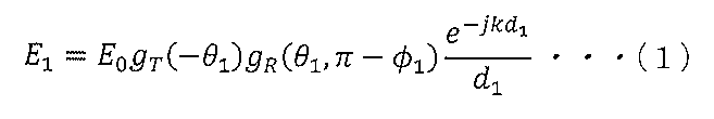

式(1),(2)において、E0は、定数であり、kは、位相定数2π/λ(λは、電波の波長である。)である。 In equations (1) and (2), E0 is a constant and k is a phase constant 2π/λ (λ is the wavelength of radio waves).
また、式(1),(2)において、φ1は、発射源S(送信点)から端末装置2(受信点)を見たときの水平角であり、θ1は、発射源S(送信点)から端末装置2(受信点)を見たときの仰角であり、θ2は、発射源S(送信点)のアンテナから反射点を見たときの俯角であり、θGは、大地反射波の入射角である。ここで、θG=π/2-θ2の関係がある。 In equations (1) and (2), φ 1 is the horizontal angle when viewing the terminal device 2 (receiving point) from the emission source S (transmission point), and θ 1 is the emission source S (transmission point). θ 2 is the angle of depression when the reflection point is viewed from the antenna of the source S (transmission point), and θ G is the ground reflection is the angle of incidence of the wave. Here, there is a relationship of θ G =π/2-θ 2 .
更に、式(1),(2)において、gT(θ)は、送信アンテナのE面指向性係数に絶対利得を乗じた関数であり、gR(θ,φ)は、受信アンテナのE面とH面に関する同様の関数である。 Furthermore, in equations (1) and (2), g T (θ) is a function obtained by multiplying the E-plane directivity coefficient of the transmitting antenna by the absolute gain, and g R (θ, φ) is the E A similar function for the plane and the H plane.
更に、式(1)におけるd1は、発射源Sから端末装置2(受信点)への直接波の経路長であり、次式(3)によって表される。 Furthermore, d1 in equation ( 1 ) is the path length of the direct wave from the emission source S to the terminal device 2 (receiving point), and is expressed by the following equation (3).
![]()
![]()
更に、式(2)におけるd2は、発射源Sからの電波の大地反射波の経路長であり、次式(4)によって表される。 Furthermore, d2 in equation ( 2 ) is the path length of the ground-reflected wave of the radio wave from source S, and is expressed by the following equation (4).
![]()
![]()
更に、式(2)において、RV(θ)は、TM入射時の大地反射係数であり、次式(5)によって表される。 Furthermore, in equation (2), R V (θ) is the ground reflection coefficient at the time of TM incidence and is expressed by the following equation (5).
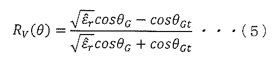
反射面の起伏の標準偏差は、波長に比べて小さいと考えられるので、粗面反射係数を適用しない。 Since the standard deviation of the undulations of the reflective surface is assumed to be small compared to the wavelength, no rough surface reflection coefficient is applied.
式(5)において、θGtは、屈折角であり、ε^r(“^”がεの上に配置されていることを表す)は、大地の複素比誘電率であり、角周波数ω、比誘電率εrおよび導電率σを用いて次式(6)によって表される。なお、スネルの法則によって屈折角θGtを求めることができる。 In equation (5), θ Gt is the angle of refraction, ε ̂ r (representing that “̂” is placed above ε) is the complex relative permittivity of the earth, the angular frequency ω, It is represented by the following equation (6) using relative dielectric constant εr and electrical conductivity σ. Note that the refraction angle θ Gt can be obtained by Snell's law.
![]()
![]()
式(6)において、ε0は、空気の誘電率である。 In equation (6), ε 0 is the dielectric constant of air.
図3は、アンテナの指向性の測定結果を示す図である。図3において、アンテナの指向性は、次の測定条件を用いて測定された。 FIG. 3 is a diagram showing measurement results of antenna directivity. In FIG. 3, the directivity of the antenna was measured using the following measurement conditions.
送信アンテナとして、ロッドアンテナを用いた。また、周波数は、1270MHzであり、偏波は、垂直偏波であり、受信アンテナは、Omni-LOG 70600(非特許文献9参照)である。 A rod antenna was used as a transmitting antenna. The frequency is 1270 MHz, the polarization is vertical polarization, and the receiving antenna is Omni-LOG 70600 (see Non-Patent Document 9).
上述したgT(θ)およびgR(θ,φ)は、図3に示す特性から求めることができる。 The g T (θ) and g R (θ, φ) described above can be obtained from the characteristics shown in FIG.
図4は、直接波、大地反射波および壁面反射波の経路を示す図である。図4を参照して、x軸方向における発射源S(送信点T)と壁面3との距離は、xWである。端末装置2の高さhrがhr<20mである場合、発射源S(送信点T)からの電波が壁面3で反射することが想定される。従って、発射源S(送信点T)からの直接波および大地反射波は、経路4を伝搬して端末装置2へ到達し、壁面3での壁面反射波は、経路5を伝搬して端末装置2へ到達する。
FIG. 4 is a diagram showing paths of direct waves, ground reflected waves, and wall reflected waves. Referring to FIG. 4, the distance between the emission source S (transmission point T) and the
壁面反射波E3は、次式(7)によって表される。 The wall - reflected wave E3 is represented by the following equation (7).
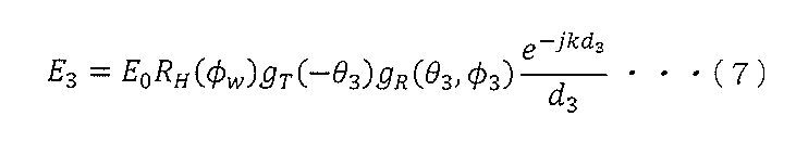
式(7)において、φ3は、送信点Tから壁面反射点を見込んだ水平角であり、θ3は、送信点Tから壁面反射点を見込んだ俯角である。 In equation (7) , φ3 is the horizontal angle from the transmission point T to the wall reflection point, and θ3 is the depression angle from the transmission point T to the wall reflection point.
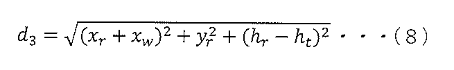
また、d3は、壁面反射波の経路長(図4に示す経路5の長さ)であり、次式(8)によって表される。
Also, d3 is the path length of the wall - reflected wave (length of
式(7)のRH(φ)は、TE入射時の反射係数であり、次式(9)によって表される。 R H (φ) in equation (7) is the reflection coefficient at the time of TE incidence and is expressed by the following equation (9).

式(9)において、φtは、屈折角であり、スネルの法則によって求めることができる。また、式(9)において、ε^Wr(“^”がεの上に配置されていることを表す)は、壁面の複素比誘電率であり、角周波数ω、壁面の比誘電率εWrおよび導電率σWを用いて次式(10)によって表される。 In Equation (9), φ t is the angle of refraction and can be obtained by Snell's law. Also, in equation (9), ε^ Wr (indicating that “^” is placed on ε) is the complex relative permittivity of the wall surface, the angular frequency ω, and the relative permittivity of the wall surface ε Wr and electrical conductivity σ W are represented by the following equation (10).

電界強度の2乗と波動インピーダンスとから受信電力RSSIを求めることができる。即ち、端末装置2の高さhrがhr≧20mである場合、端末装置2(受信点R)における受信電力PR,hr≧20は、上述した式(1),(2)を用いて、次式(11)によって表される。
The received power RSSI can be obtained from the square of the electric field intensity and the wave impedance. That is, when the height h r of the

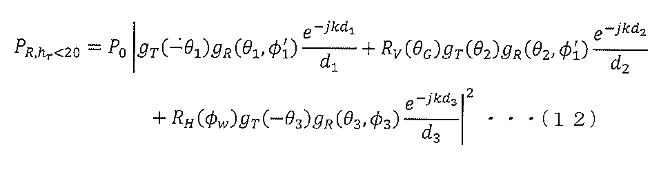
また、端末装置2の高さhrがhr<20mである場合、端末装置2(受信点R)における受信電力PR,hr<20は、上述した式(1),(2),(7)を用いて、次式(12)によって表される。
Further, when the height h r of the
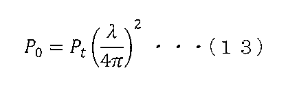
式(11),(12)において、φ’1は、φ’1=π-φ1である。また、式(11),(12)におけるP0は、フリスの伝達公式と整合が取れるように、送信電力をPtとして次式(13)によって決定される。 In equations (11) and (12), φ' 1 is φ' 1 =π-φ 1 . P 0 in equations (11) and (12) is determined by the following equation (13) with transmission power as P t so as to match the Friis transfer formula.
式(11)において、右辺の電界強度の2乗を表す項において、第1項は、直接波を表し、第2項は、大地反射波を表す。従って、式(11)は、直接波および大地反射波(=1回反射波)を用いて受信電力PR,hr≧20を求める電波の伝搬モデルを表す。 In equation (11), in terms representing the square of the electric field strength on the right side, the first term represents a direct wave, and the second term represents a ground reflected wave. Therefore, Equation (11) represents a radio wave propagation model for obtaining the received power P R,hr ≧20 using the direct wave and the ground reflected wave (=one-time reflected wave).
また、式(12)において、右辺の電界強度の2乗を表す項において、第1項は、直接波を表し、第2項は、大地反射波を表し、第3項は、壁面反射波を表す。従って、式(12)は、直接波、大地反射波(=1回反射波)および壁面反射波を用いて受信電力PR,hr<20を求める電波の伝搬モデルを表す。 Further, in equation (12), in the term representing the square of the electric field intensity on the right side, the first term represents the direct wave, the second term represents the ground reflected wave, and the third term represents the wall reflected wave. show. Therefore, Equation (12) expresses a radio wave propagation model that obtains the received power P R,hr <20 using the direct wave, ground reflected wave (=single reflected wave), and wall reflected wave.
式(11)または式(12)を用いて受信電力RSSIを計算するときに必要な反射係数を求めるための電気定数を表1に示す。 Table 1 shows the electrical constants for determining the reflection coefficient required when calculating the received power RSSI using Equation (11) or Equation (12).
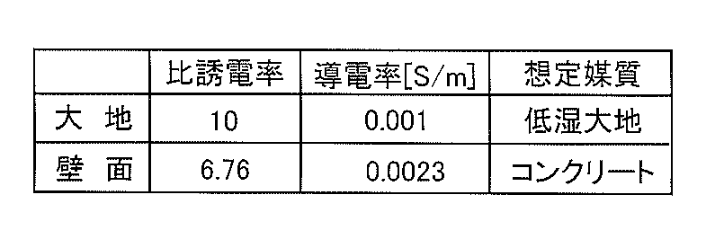
表1における想定媒質としての「低湿大地」は、非特許文献5に記載されており、想定媒質としての「コンクリート」は、非特許文献10に記載されている。
"Low wet earth" as the assumed medium in Table 1 is described in
この発明の実施の形態においては、表1に示す比誘電率および導電率を用いて反射係数を算出した。 In the embodiment of the present invention, the reflection coefficient was calculated using the relative permittivity and conductivity shown in Table 1.
図5は、反射係数と入射角との関係を示す図である。図5において、縦軸は、反射係数を表し、横軸は、入射角を表す。また、実線は、壁面へのTE入射における反射係数と入射角との関係を示し、破線は、大地へのTM入射における反射係数と入射角との関係を示す。なお、図5に示す反射係数は、表1に示す電気定数を用いて計算された計算値である。 FIG. 5 is a diagram showing the relationship between the reflection coefficient and the incident angle. In FIG. 5, the vertical axis represents the reflection coefficient and the horizontal axis represents the angle of incidence. The solid line indicates the relationship between the reflection coefficient and the angle of incidence for TE incident on the wall, and the dashed line indicates the relationship between the reflection coefficient and the angle of incidence for TM incident on the ground. Note that the reflection coefficients shown in FIG. 5 are calculated values calculated using the electrical constants shown in Table 1.
図5を参照して、TE入射(壁面)においては、反射係数は、入射角の増加に伴って徐々に大きくなる。一方、TM入射(大地)においては、反射係数は、入射角が約70度までの範囲においては、入射角の増加に伴って徐々に低下し、約70度の入射角において最小になる。そして、入射角が約70度よりも大きくなると、反射係数は、入射角の増加に伴って指数関数的に大きくなる。 Referring to FIG. 5, at TE incidence (wall), the reflection coefficient gradually increases as the incidence angle increases. On the other hand, for TM incidence (ground), the reflection coefficient gradually decreases with increasing incidence angle up to about 70 degrees, and reaches a minimum at about 70 degrees. Then, when the incident angle is greater than about 70 degrees, the reflection coefficient increases exponentially with increasing incident angle.
電力推定手段13は、式(11)に示す電波の伝搬モデルMDL1と、式(12)に示す電波の伝搬モデルMDL2とを受信電力を推定する位置[xr,yr,hr]の高さhrに対応付けて保持する。より具体的には、電力推定手段13は、20m以上の高さhrに対応付けて電波の伝搬モデルMDL1を保持し、20mよりも低い高さhrに対応付けて電波の伝搬モデルMDL2を保持する。 The power estimating means 13 uses the radio wave propagation model MDL1 shown in Equation (11) and the radio wave propagation model MDL2 shown in Equation (12) to estimate the received power at the position [x r , yr , hr ] . It is stored in association with shr . More specifically, the power estimating means 13 stores the radio wave propagation model MDL1 in association with heights hr equal to or greater than 20 m, and stores the radio wave propagation model MDL2 in association with heights hr lower than 20 m . Hold.
また、電力推定手段13は、図5に示すTM入射(大地)における反射係数と入射角との関係RLT1と、TE入射(壁面)における反射係数と入射角との関係RET2とを保持する。
The
そして、電力推定手段13は、電波の周波数fと、送信電力Ptと、発射源Sの位置[xt,yt,zt]と、受信電力を推定する位置[xr,yr,hr]と、発射源Sの位置[xt,yt,zt]と壁面との水平方向の距離xWとを受けると、大地における反射点の位置[xRV,yRV,hRV]と、壁面における反射点の位置[xRH,yRH,hRH]とを算出する。なお、電力推定手段13は、大地の反射面に対して受信点Rの対称な鏡像を作成し、送信点Tと受信点Rの鏡像とを直線で結んだときの直線と反射面との交点を反射点の位置[xRV,yRV,hRV]として算出する。また、電力推定手段13は、同様にして、反射点の位置[xRH,yRH,hRH]を算出する。
Then, the
その後、電力推定手段13は、距離xW、位置[xt,yt,ht]、位置[xr,yr,hr]、位置[xRV,yRV,hRV]および位置[xRH,yRH,hRH]を用いて、上述した水平角φ1、仰角θ1、俯角θ2、入射角θG、入射角φW、水平角φ3および俯角θ3を算出する。また、電力推定手段13は、位置[xt,yt,ht]および位置[xr,yr,hr]を用いて、式(3),(4),(8)によってそれぞれ経路長d1,d2,d3を算出する。更に、電力推定手段13は、φ’1=π-φ1によってφ’1を算出し、スネルの法則によって屈折角φGt,φtを求める。更に、電力推定手段13は、入射角θG、屈折角φGtおよび式(5),(6)に基づいて反射係数RV(θG)を算出し、入射角φW、屈折角φtおよび式(9),(10)に基づいて反射係数RH(φW)を算出する。更に、電力推定手段13は、周波数fに基づいて電波の波長λを算出し、その算出した波長λと送信電力Ptとを式(13)に代入して定数P0を算出する。なお、波長λは、光速c/周波数fによって算出される。
After that, the power estimation means 13 calculates the distance x W , the position [x t , y t , h t ], the position [x r , yr , hr ], the position [ x RV , y RV , h RV ] and the position [ x RH , y RH , h RH ] are used to calculate the horizontal angle φ 1 , elevation angle θ 1 , depression angle θ 2 , incident angle θ G , incident angle φ W , horizontal angle φ 3 and depression angle θ 3 . Also, the
そうすると、電力推定手段13は、位置[xr,yr,hr]の高さhrがhr≧20mであるとき、定数P0、仰角θ1、水平角φ’1、反射係数RV(θG)、俯角θ2、および経路長d1,d2を式(11)に代入してPR,hr≧20を算出し、その算出したPR,hr≧20を位置[xr,yr,zr]における受信電力RSSI_ESTとして推定する。
Then, when the height h r of the position [x r , y r , h r ] is h r ≧20 m, the
また、電力推定手段13は、位置[xr,yr,hr]の高さhrがhr<20mであるとき、定数P0、仰角θ1、水平角φ’1、水平角φ3、反射係数RV(θG)、反射係数RH(θW)、俯角θ2、俯角θ3および経路長d1,d2,d3を式(12)に代入してPR,hr<20を算出し、その算出したPR,hr<20を位置[xr,yr,hr]における受信電力RSSI_ESTとして推定する。 Further, when the height h r of the position [x r , y r , h r ] is h r <20 m, the power estimating means 13 calculates the constant P 0 , the elevation angle θ 1 , the horizontal angle φ′ 1 , the horizontal angle φ 3 , the reflection coefficient R V (θ G ), the reflection coefficient R H (θ W ), the depression angle θ 2 , the depression angle θ 3 and the path lengths d 1 , d 2 , and d 3 are substituted into the equation (12) to obtain PR , Calculate hr <20, and estimate the calculated PR , hr<20 as the received power RSSI_EST at location [x r , yr , hr ].
即ち、電力推定手段13は、位置[xr,yr,hr]の高さhrがhr≧20mであるとき、電波の伝搬モデルMDL1に基づいて位置[xr,yr,hr]における受信電力RSSI_ESTを推定し、位置[xr,yr,hr]の高さhrがhr<20mであるとき、電波の伝搬モデルMDL2に基づいて位置[xr,yr,hr]における受信電力RSSI_ESTを推定する。 That is, when the height h r of the position [x r , y r , h r ] is h r ≧20 m, the power estimating means 13 calculates the position [x r , y r , h r ] and estimate the position [ x r , yr , h r ].
電力推定手段13が電波の伝搬モデルMDL1または電波の伝搬モデルMDL2に基づいて受信電力RSSI_ESTを推定することは、電力推定手段13が電波の伝搬環境に適合した伝搬モデルを用いて受信電力RSSI_ESTを推定することに相当する。電波の伝搬モデルMDL1は、建物の高さ(=20m)以上の領域における電波の伝搬モデルであり、電波の伝搬モデルMDL2は、建物の高さ(=20m)よりも低い領域における電波の伝搬モデルであるからである。 Estimating the received power RSSI_EST by the power estimating means 13 based on the radio wave propagation model MDL1 or the radio wave propagation model MDL2 means that the power estimating means 13 estimates the received power RSSI_EST using a propagation model suitable for the radio wave propagation environment. equivalent to The radio wave propagation model MDL1 is a radio wave propagation model in an area above the building height (=20 m), and the radio wave propagation model MDL2 is a radio wave propagation model in an area below the building height (=20 m). Because it is.
また、電力推定手段13が電波の伝搬モデルMDL1または電波の伝搬モデルMDL2に基づいて受信電力RSSI_ESTを推定することは、発射源Sの配置位置の高さと建物の高さとの比較結果に応じて異なる伝搬モデルに基づいて受信電力を推定することに相当する。電力推定手段13は、発射源Sの配置位置の高さが建物の高さ以上である場合、伝搬モデルMDL1を用いて受信電力RSSI_ESTを推定し、発射源Sの配置位置の高さが建物の高さよりも低い場合、伝搬モデルMDL2を用いて受信電力RSSI_ESTを推定し、伝搬モデルMDL1,MDL2は、それぞれ式(11),(12)に示すように相互に異なる伝搬モデルであるからである。 Further, the estimation of the received power RSSI_EST by the power estimating means 13 based on the radio wave propagation model MDL1 or the radio wave propagation model MDL2 differs depending on the result of comparison between the height of the arrangement position of the emission source S and the height of the building. This corresponds to estimating the received power based on the propagation model. The power estimating means 13 estimates the received power RSSI_EST using the propagation model MDL1 when the height of the arrangement position of the emission source S is equal to or higher than the height of the building. This is because when the height is lower than the height, the received power RSSI_EST is estimated using the propagation model MDL2, and the propagation models MDL1 and MDL2 are different propagation models as shown in equations (11) and (12), respectively.
図6は、電波の受信電力を測定する環境を説明するための図である。なお、図6においては、上空から見た電波の伝搬環境を示す。 FIG. 6 is a diagram for explaining the environment in which the received power of radio waves is measured. Note that FIG. 6 shows the radio wave propagation environment as seen from above.
図6を参照して、建物6,7が存在し、建物6は、建物7よりも低く、例えば、20mの高さを有する。建物7は、壁面7Hを有し、20mよりも高い高さを有する。建物6,7に近接する地面には、樹木8が植えられている。領域REGは、グランドであり、舗装路面から10cm程度盛り上がっている。
Referring to FIG. 6, there are
図6の紙面において、右方向が東方向であり、左方向が西方向であり、上方向が北方向であり、下方向が南方向である。従って、x軸は、東西方向に平行に配置され、x軸の正方向が東方向である。また、y軸は、南北方向に平行に配置され、y軸の正方向は、北方向である。 6, the right direction is the east direction, the left direction is the west direction, the upward direction is the north direction, and the downward direction is the south direction. Thus, the x-axis is arranged parallel to the east-west direction, with the positive direction of the x-axis being the east direction. Also, the y-axis is arranged parallel to the north-south direction, and the positive direction of the y-axis is the north direction.
送信点Tは、建物6の屋上において、位置[0,0,20]に配置されている。また、受信点Rの位置は、[xr,yr,hr]によって表される。 The transmission point T is placed at position [0, 0, 20] on the roof of building 6 . Also, the position of the reception point R is represented by [x r , y r , hr ].
送信点Tから発射された電波の直接波および大地反射波は、太線の矢印で示す経路に沿って送信点Tから受信点Rに到達する。 A direct wave and ground-reflected radio waves emitted from the transmission point T reach the reception point R from the transmission point T along the paths indicated by the thick arrows.
また、送信点Tから発射された電波の壁面反射波は、破線の矢印で示す経路に沿って送信点Tから受信点Rに到達する。即ち、壁面反射波は、建物7の壁面7Hで反射して受信点Rに到達する。
A wall-reflected wave of the radio wave emitted from the transmission point T reaches the reception point R from the transmission point T along the route indicated by the dashed arrow. That is, the wall-reflected wave reaches the reception point R after being reflected by the
そして、受信機を搭載したドローンを用いて、高さ5m、10mおよび30mにおいて、送信点Tから発射された電波の受信電力RSSI_MESを測定した。ドローンは、定速で西から東へ3往復飛行し、その間、計継続的に受信電力RSSI_MESを測定して記録する。受信点Rの位置[xr,yr,hr]の範囲は、東西方向xrが2~100mの範囲であり、南北方向yrが-37~-52mの範囲である。また、受信電力の測定間隔は、東西方向が1.6m程度であり、南北方向が3m程度である。 Then, using a drone equipped with a receiver, the received power RSSI_MES of radio waves emitted from the transmission point T was measured at heights of 5 m, 10 m and 30 m. The drone flies three round trips from west to east at a constant speed, during which time the received power RSSI_MES is continuously measured and recorded. The range of the position [x r , y r , h r ] of the receiving point R is 2 to 100 m in the east-west direction x r and -37 to -52 m in the north-south direction y r . The measurement interval of received power is about 1.6 m in the east-west direction and about 3 m in the north-south direction.
点線9は、ドローンが5mの高さで飛行経路12を飛行したときの大地反射点の軌跡を示し、実線10は、ドローンが10mの高さで飛行経路12を飛行したときの大地反射点の軌跡を示し、実線11は、ドローンが30mの高さで飛行経路12を飛行したときの大地反射点の軌跡を示す。
A dotted
従って、大地反射点の位置は、受信点Rの高さhrが高くなるに従って、南北方向において送信点Tに近くなり、東西方向における大地反射点の軌跡の長さは、受信点Rの高さhrが高くなるに従って短くなる。 Therefore, the position of the ground reflection point becomes closer to the transmission point T in the north-south direction as the height hr of the reception point R increases, and the length of the locus of the ground reflection point in the east-west direction becomes It becomes shorter as the height r increases.
図7は、図1に示す記憶手段12における受信電力RSSI_MESの記憶方式を示す図である。 FIG. 7 is a diagram showing a storage method of received power RSSI_MES in storage means 12 shown in FIG.
図7を参照して、記憶手段12は、対応表TBLを保持する。対応表TBLは、周波数fと、位置[xr,yr,hr]と、受信電力RSSI_MESとを含む。周波数f、位置[xr,yr,hr]および受信電力RSSI_MESは、相互に対応付けられる。 Referring to FIG. 7, storage means 12 holds correspondence table TBL. The correspondence table TBL includes frequency f, position [x r , yr , hr ] and received power RSSI_MES . The frequency f, the position [xr, yr , hr ] and the received power RSSI_MES are associated with each other.
周波数fは、複数の端末装置2が共用する共用周波数である。位置[xr,yr,hr]は、発射源S(送信点T)から発射された電波の受信電力を測定する位置である。受信電力RSSI_MESは、図6に示す方法で測定された受信電力である。
A frequency f is a shared frequency shared by a plurality of
位置[xr1_1,yr1_1,hr1_1],[xr2_1,yr2_1,hr2_1],・・・,[xrn_1,yrn_1,hrn_1]および受信電力RSSI1_1,RSSI2_1,・・・,RSSIn_1は、周波数f1に対応付けられ、位置[xr1_2,yr1_2,hr1_2],[xr2_2,yr2_2,hr2_2],・・・,[xrn_2,yrn_2,hrn_2]および受信電力RSSI1_2,RSSI2_2,・・・,RSSIn_2は、周波数f2に対応付けられ、以下、同様にした、位置[xr1_m,yr1_m,hr1_m],[xr2_m,yr2_m,hr2_m],・・・,[xrn_m,yrn_m,hrn_m]および受信電力RSSI1_m,RSSI2_m,・・・,RSSIn_mは、周波数fmに対応付けられる。ここで、nおよびmの各々は、正の整数であり、nは、周波数f1~fmの各々における受信電力RSSI_MESの測定個数を表し、mは、共用周波数の個数を表す。 Positions [ xr1_1 , yr1_1 , hr1_1 ], [ xr2_1 , yr2_1 , hr2_1 ], ..., [ xrn_1 , yrn_1 , hr2_1 ] and received power RSSI1_1 , RSSI2_1 , ..., RSSI n_1 is associated with frequency f 1 and has locations [x r1_2 , y r1_2 , h r1_2 ], [x r2_2 , y r2_2 , h r2_2 ] , . The received powers RSSI1_2 , RSSI2_2 , . _ r2_m ] , . _ _ _ _ Here, each of n and m is a positive integer, n represents the number of measurements of received power RSSI_MES in each of frequencies f 1 to f m , and m represents the number of shared frequencies.
なお、図7においては、受信電力RSSI_MESの測定個数nは、周波数f1~fmの各々において同じであるが、この発明の実施の形態においては、受信電力RSSI_MESの測定個数nは、周波数f1~fmにおいて相互に異なっていてもよい。 In FIG. 7, the number n of measurements of received power RSSI_MES is the same for each of frequencies f 1 to f m . 1 to f m may be different from each other.
記憶手段12は、受付手段11から測定データD=[f/[xr,yr,hr]/RSSI]を受けると、測定データDの周波数f、位置[xr,yr,hr]および受信電力RSSIをそれぞれ対応表TBLの周波数f、位置[xr,yr,hr]および受信電力RSSI_MESの欄に格納して記憶する。 Upon receipt of the measurement data D=[f/[ xr , yr , hr ]/RSSI] from the receiving means 11, the storage means 12 stores the frequency f and the position [ xr , yr , hr ] of the measurement data D. ] and received power RSSI are respectively stored in the fields of frequency f, position [x r , yr , hr ] and received power RSSI_MES of the correspondence table TBL.
品質推定手段14は、電波品質を推定する電波の周波数fANAおよび電波品質を推定する位置の位置情報PS_ANAを受付手段11から受けると、記憶手段12に記憶された対応表TBLを参照して、周波数fANAおよび位置情報PS_ANAに対応する受信電力RSSIi_j(iは、1≦i≦nを満たす整数、jは、1≦j≦mを満たす整数)を受信電力RSSI_MESとして読み出す。 The quality estimating means 14 receives from the receiving means 11 the frequency f ANA of the radio wave for which the radio wave quality is to be estimated and the location information P S_ANA of the position for estimating the radio wave quality, and refers to the correspondence table TBL stored in the storing means 12. , the received power RSSI i_j (i is an integer satisfying 1≦i≦n and j is an integer satisfying 1≦j≦m) corresponding to the frequency f ANA and the position information P S_ANA are read as the received power RSSI_MES.
また、品質推定手段14は、受信電力RSSI_ESTを電力推定手段13から受ける。そして、品質推定手段14は、受信電力の比RSSI_Ratio=RSSI_EST/(RSSI_EST+RSSI_MES)を演算し、その演算した、受信電力の比RSSI_Ratioを電波品質として推定する。 Also, the quality estimation means 14 receives the received power RSSI_EST from the power estimation means 13 . Then, the quality estimation means 14 calculates the received power ratio RSSI_Ratio=RSSI_EST/(RSSI_EST+RSSI_MES), and estimates the calculated received power ratio RSSI_Ratio as the radio wave quality.
RSSI_EST/(RSSI_EST+RSSI_MES)を変形すると、1/(1+RSSI_MES/RSSI_EST)となる。RSSI_MES/RSSI_EST=aとすると、受信電力の比RSSI_Ratioは、RSSI_Ratio=1/(1+a)となる。 RSSI_EST/(RSSI_EST+RSSI_MES) is transformed into 1/(1+RSSI_MES/RSSI_EST). If RSSI_MES/RSSI_EST=a, then the received power ratio RSSI_Ratio is RSSI_Ratio=1/(1+a).
図8は、受信電力の比RSSI_Ratioとaとの関係を示す図である。図8において、縦軸は、受信電力の比RSSI_Ratioを表し、横軸は、a(=RSSI_MES/RSSI_EST)を表す。曲線k1は、受信電力の比RSSI_Ratioとaとの関係を示す。 FIG. 8 is a diagram showing the relationship between the received power ratio RSSI_Ratio and a. In FIG. 8, the vertical axis represents the received power ratio RSSI_Ratio, and the horizontal axis represents a (=RSSI_MES/RSSI_EST). A curve k1 shows the relationship between the received power ratio RSSI_Ratio and a.
図8を参照して、受信電力の比RSSI_Ratioは、aの増加に伴って減少する(曲線k1参照)。受信電力RSSI_ESTが受信電力RSSI_MESに一致する場合(即ち、a=1である場合)、受信電力の比RSSI_Ratioは、0.5となり、推定された電波品質は、最も良い。 Referring to FIG. 8, the received power ratio RSSI_Ratio decreases as a increases (see curve k1). When the received power RSSI_EST matches the received power RSSI_MES (that is, when a=1), the received power ratio RSSI_Ratio is 0.5, and the estimated radio wave quality is the best.
推定された受信電力RSSI_ESTが測定された受信電力RSSI_MESよりも小さくなると、aは、1よりも大きくなり、受信電力の比RSSI_Ratioは、0.5よりも小さくなる。 If the estimated received power RSSI_EST is less than the measured received power RSSI_MES, a will be greater than 1 and the ratio of received powers RSSI_Ratio will be less than 0.5.
また、推定された受信電力RSSI_ESTが測定された受信電力RSSI_MESよりも大きくなると、aは、1よりも小さくなり、受信電力の比RSSI_Ratioは、0.5よりも大きくなる。 Also, when the estimated received power RSSI_EST is greater than the measured received power RSSI_MES, a becomes less than 1 and the received power ratio RSSI_Ratio becomes greater than 0.5.
従って、推定された電波品質は、受信電力の比RSSI_Ratioが0.5からずれに従って低下する。 Therefore, the estimated radio wave quality decreases as the received power ratio RSSI_Ratio deviates from 0.5.
このように、この発明の実施の形態によれば、上空における電波品質を容易に推定できる。 Thus, according to the embodiment of the present invention, radio wave quality in the sky can be easily estimated.
なお、図8においては、RSSI_MES/RSSI_EST=aとしたが、この発明の実施の形態においては、RSSI_EST/RSSI_MES=aとしてもよい。この場合、受信電力の比RSSI_Ratio=a/(1+a)となる。そして、受信電力の比RSSI_Ratioを表す曲線は、図8に示す曲線k1を縦軸および横軸の両軸に対称に反転させた曲線になり、受信電力RSSI_ESTが受信電力RSSI_MESに一致する場合(即ち、a=1である場合)、受信電力の比RSSI_Ratioは、0.5となり、推定された電波品質は、最も良い。また、受信電力RSSI_ESTが受信電力RSSI_MESと異なる場合、受信電力の比RSSI_Ratioは、0.5からずれ、電波品質は、低下する。 Although RSSI_MES/RSSI_EST=a in FIG. 8, RSSI_EST/RSSI_MES=a may be set in the embodiment of the present invention. In this case, the received power ratio RSSI_Ratio=a/(1+a). Then, the curve representing the received power ratio RSSI_Ratio is a curve obtained by symmetrically inverting the curve k1 shown in FIG. , a=1), the received power ratio RSSI_Ratio is 0.5, and the estimated radio wave quality is the best. Also, when the received power RSSI_EST differs from the received power RSSI_MES, the received power ratio RSSI_Ratio deviates from 0.5, and the radio wave quality deteriorates.
従って、RSSI_MES/RSSI_EST=aである場合、およびRSSI_EST/RSSI_MES=aである場合の両方において、受信電力の比RSSI_Ratioによって電波品質を推定できる。 Therefore, both when RSSI_MES/RSSI_EST=a and when RSSI_EST/RSSI_MES=a, the radio wave quality can be estimated from the received power ratio RSSI_Ratio.
図9は、図1に示す電波品質推定装置1の動作を説明するためのフローチャートである。なお、図9においては、受付手段11は、測定データDを受け付け、その受け付けた測定データDを記憶手段12に記憶していることを前提として電波品質推定装置1の動作を説明する。
FIG. 9 is a flow chart for explaining the operation of the radio wave
図9を参照して、電波品質推定装置1の動作が開始されると、受付手段11は、電波品質を推定する電波の周波数fANA(=f1~fm)、発射源Sの位置を示す位置情報PS_SRC=[xt,yt,ht]、環境情報INFOCIRおよび受信電力の推定位置を示す位置情報PS_ANA=[xri_j,yri_j,hri_j]を受け付ける(ステップS1)。
Referring to FIG. 9, when the operation of radio wave
そして、受付手段11は、その受け付けた周波数fANA(=f1~fm)、位置情報PS_ANA=[xri_j,yri_j,hri_j]、位置情報PS_SRC=[xt,yt,ht]および環境情報INFOCIRを電力推定手段13へ出力し、その受け付けた周波数fANA(=f1~fm)および位置情報PS_ANA=[xri_j,yri_j,hri_j]を品質推定手段14へ出力する。 Then, the receiving means 11 receives the frequency f ANA (=f 1 to f m ), the location information P S_ANA =[x ri_j , y ri_j , h ri_j ], the location information P S_SRC =[x t , y t , h t ] and the environment information INFO CIR to the power estimation means 13, and the received frequency f ANA (=f 1 to f m ) and position information P S_ANA =[x ri_j , y ri_j , h ri_j ] are used for quality estimation. Output to means 14 .
電力推定手段13は、周波数fANA(=f1~fm)、位置情報PS_ANA=[xri_j,yri_j,hri_j]、位置情報PS_SRC=[xt,yt,ht]および環境情報INFOCIRを受付手段11から受ける。また、品質推定手段14は、周波数fANA(=f1~fm)および位置情報PS_ANA=[xri_j,yri_j,hri_j]を受付手段11から受ける。 The power estimating means 13 includes frequency f ANA (=f 1 to f m ), location information P S_ANA =[x ri_j , y ri_j , h ri_j ], location information P S_SRC =[x t , y t , h t ] and The environment information INFO CIR is received from the receiving means 11 . Also, the quality estimation means 14 receives the frequency f ANA (=f 1 to f m ) and the position information P S_ANA =[x ri — j , y ri — j , h ri — j ] from the reception means 11 .
そして、電力推定手段13は、j=1を設定し(ステップS2)、i=1を設定する(ステップS3)。その後、電力推定手段13は、環境情報INFOCIRに基づいて、電波の伝搬環境に適合した電波の伝搬モデルを選択し、その選択した電波の伝搬モデルに基づいて、周波数fjを有する電波の位置[xri_j,yri_j,hri_j]における受信電力RSSI_ESTi_jを推定する(ステップS4)。そして、電力推定手段13は、その推定した受信電力RSSI_ESTi_jを品質推定手段14へ出力する。
Then, the
品質推定手段14は、受信電力RSSI_ESTi_jを電力推定手段13から受ける。そして、品質推定手段14は、周波数fjおよび位置情報PS_ANAに基づいて、周波数fjおよび位置[xri_j,yri_j,hri_j]に対応する受信電力RSSI_MESi_j(測定された受信電力)を記憶手段12から読み出す(ステップS5)。
The
その後、品質推定手段14は、受信電力の比RSSI_Ratioi_j=RSSI_ESTi_j/(RSSI_ESTi_j+RSSI_MESi_j)を演算し(ステップS6)、その演算した受信電力の比RSSI_Ratioi_jを電波品質として推定する(ステップS7)。 After that, the quality estimation means 14 calculates the ratio RSSI_Ratioi_j of the received power = RSSI_ESTi_j /( RSSI_ESTi_j + RSSI_MESi_j ) (step S6), and estimates the calculated ratio RSSI_Ratioi_j of the received power as the radio wave quality (step S7). ).
そして、電力推定手段13は、i=nであるか否かを判定する(ステップS8)。ステップS8において、i=nでないと判定されたとき、電力推定手段13は、i=i+1を設定する(ステップS9)。その後、一連の動作は、ステップS4へ移行し、ステップS8において、i=nであると判定されるまで、ステップS4~ステップS9が繰り返し実行される。
Then, the
そして、ステップS8において、i=nであると判定されると、電力推定手段13は、j=mであるか否かを更に判定する(ステップS10)。
When it is determined in step S8 that i=n, the
ステップS10において、j=mでないと判定されたとき、電力推定手段13は、j=j+1を設定する(ステップS11)。その後、一連の動作は、ステップS3へ移行し、ステップS10において、j=mであると判定されるまで、ステップS3~ステップS11が繰り返し実行される。
When it is determined in step S10 that j=m is not true, the
そして、ステップS10において、j=mであると判定されると、電力推定手段13は、電波品質の推定が完了したことを示す信号SCOMPを生成して品質推定手段14へ出力する。 Then, when it is determined in step S10 that j=m, the power estimating means 13 generates a signal S-- COMP indicating that the radio wave quality estimation has been completed, and outputs it to the quality estimating means 14. FIG.
品質推定手段14は、信号SCOMPを電力推定手段13から受けると、電波品質RSSI_Ratio1_1~RSSI_Ration_mを出力する(ステップS12)。これによって、電波品質推定装置1の動作が終了する。
Quality estimating means 14, upon receiving signal S COMP from power estimating means 13, outputs radio wave qualities RSSI_Ratio 1_1 to RSSI_Ratio n_m (step S12). This completes the operation of the radio wave
図10は、図9のステップS4の詳細な動作を説明するためのフローチャートである。図10を参照して、図9のステップS3の後、電力推定手段13は、電波の伝搬モデルにおけるパラメータを算出する(ステップS41)。そして、電力推定手段13は、環境情報INFOCIRから建物の高さを検出し、位置[xt,yt,ht]から高さhtを検出する。そうすると、電力推定手段13は、その検出した高さhtが建物の高さ以上であるか否かを判定する(ステップS42)。即ち、電力推定手段13は、発射源Sの配置位置の高さhtが建物の高さ以上であるか否かを判定する。 FIG. 10 is a flow chart for explaining the detailed operation of step S4 in FIG. Referring to FIG. 10, after step S3 in FIG. 9, power estimating means 13 calculates parameters in the radio wave propagation model (step S41). Then, the power estimating means 13 detects the height of the building from the environmental information INFO CIR , and detects the height ht from the position [ xt , yt , ht ]. Then, the power estimating means 13 determines whether or not the detected height ht is equal to or higher than the height of the building (step S42). That is, the power estimating means 13 determines whether or not the height ht of the position where the emission source S is arranged is greater than or equal to the height of the building.
ステップS42において、高さhtが建物の高さ以上であると判定されたとき、電力推定手段13は、電波の伝搬モデルMDL1に基づいて位置[xri_j,yri_j,hri_j]における電波の受信電力RSSI_ESTi_jを推定する(ステップS43)。 In step S42, when it is determined that the height ht is equal to or greater than the height of the building, the power estimating means 13 calculates the height of the radio waves at the position [xri_j, yri_j , hri_j ] based on the radio wave propagation model MDL1. The received power RSSI_EST i_j is estimated (step S43).
一方、ステップS42において、高さhtが建物の高さ以上でないと判定されたとき、電力推定手段13は、電波の伝搬モデルMDL2に基づいて位置[xri_j,yri_j,hri_j]における電波の受信電力RSSI_ESTi_jを推定する(ステップS44)。そして、ステップS43またはステップS44の後、一連の動作は、図9のステップS5へ移行する。 On the other hand, when it is determined in step S42 that the height h t is not equal to or greater than the height of the building, the power estimating means 13 generates the radio wave receive power RSSI_EST i_j (step S44). After step S43 or step S44, the series of operations proceeds to step S5 in FIG.
図11は、図10のステップS41の詳細な動作を説明するためのフローチャートである。図11を参照して、図9のステップS3の後、電力推定手段13は、距離xW、位置[xt,yt,ht]、位置[xri_j,yri_j,hri_j]、位置[xRV,yRV,hRV]および位置[xRH,yRH,hRH]を用いて、水平角φ1,φ3、仰角θ1、俯角θ2,θ3および入射角θG,φWを算出する(ステップS411)。この場合、電力推定手段13は、環境情報INFOCIRから距離xW、位置[xRV,yRV,hRV]および位置[xRH,yRH,hRH]を検出し、その検出した距離xW、位置[xRV,yRV,hRV]および位置[xRH,yRH,hRH]を用いて水平角φ1,φ3、仰角θ1、俯角θ2,θ3および入射角θG,φWを算出する。 FIG. 11 is a flow chart for explaining the detailed operation of step S41 of FIG. Referring to FIG. 11, after step S3 in FIG. 9, power estimating means 13 determines distance xW, position [xt, yt, ht], position [xri_j , yri_j , hri_j ] , position Using [x RV , y RV , h RV ] and position [x RH , y RH , h RH ], horizontal angles φ 1 , φ 3 , elevation angles θ 1 , depression angles θ 2 , θ 3 and incident angles θ G , φ W is calculated (step S411). In this case, the power estimation means 13 detects the distance x W , the position [x RV , y RV , h RV ] and the position [x RH , y RH , h RH ] from the environment information INFO CIR , and the detected distance x Horizontal angles φ 1 , φ 3 , elevation angles θ 1 , depression angles θ 2 , θ 3 and incident angles θ Calculate G and φW .
ステップS411の後、電力推定手段13は、位置[xt,yt,ht]および位置[xri_j,yri_j,hri_j]を用いて、式(3),(4),(8)によってそれぞれ経路長d1,d2,d3を算出する(ステップS412)。 After step S411, the power estimating means 13 uses the position [x t , y t , h t ] and the position [x ri — j , y ri — j , h ri — j ] to obtain equations (3), (4), (8) Then, the path lengths d 1 , d 2 and d 3 are calculated (step S412).
そして、電力推定手段13は、ステップS411において算出した水平角φ1を用いてφ’1=π-φ1によって水平角φ’1を算出する(ステップS413)。
Then, the
その後、電力推定手段13は、フレネルの法則によって屈折角φGt,φtを求める(ステップS414)。
After that, the
引き続いて、電力推定手段13は、入射角θGおよび屈折角φGtを用いて式(5),(6)によって反射係数RV(θG)を算出し、入射角φWおよび屈折角φtを用いて式(9),(10)によって反射係数RH(φW)を算出する(ステップS415)。 Subsequently, the power estimating means 13 calculates the reflection coefficient R V (θ G ) by Equations (5) and (6) using the incident angle θ G and the refraction angle φ Gt , and calculates the incident angle φ W and the refraction angle φ Using t , the reflection coefficient R H (φ W ) is calculated by equations (9) and (10) (step S415).
そして、電力推定手段13は、環境情報INFOCIRから発射源Sの送信電力Ptを検出し、周波数fjに基づいて電波の波長λjを算出し、その算出した波長λjと、送信電力Ptとを用いて式(13)によって定数P0を算出する(ステップS416)。その後、一連の動作は、図10のステップS42へ移行する。 Then, the power estimating means 13 detects the transmission power Pt of the emission source S from the environmental information INFO CIR , calculates the wavelength λ j of the radio wave based on the frequency f j , and calculates the calculated wavelength λ j and the transmission power A constant P 0 is calculated by the equation (13) using P t (step S416). After that, the series of operations proceeds to step S42 in FIG.
図12は、図10のステップS43の詳細な動作を説明するためのフローチャートである。図12を参照して、図10のステップS42において、高さhtが建物の高さ以上であると判定されたとき、電力推定手段13は、定数P0、仰角θ1、水平角φ’1、俯角θ2、反射係数RV(θG)および経路長d1,d2を式(11)に代入して受信電力PR,hr≧20を算出する(ステップS431)。 FIG. 12 is a flow chart for explaining the detailed operation of step S43 of FIG. Referring to FIG. 12, when it is determined in step S42 of FIG. 10 that the height ht is equal to or greater than the height of the building, power estimating means 13 sets constant P 0 , elevation angle θ 1 , horizontal angle φ′ 1 , the depression angle θ 2 , the reflection coefficient R V (θ G ), and the path lengths d 1 and d 2 are substituted into the equation (11) to calculate the received power P R,hr≧20 (step S431).
そして、電力推定手段13は、その算出した受信電力PR,hr≧20を位置[xri_j,yri_j,hri_j]における受信電力RSSI_ESTi_jとして推定する(ステップS432)。その後、一連の動作は、図9のステップS5へ移行する。
The
図13は、図10のステップS44の詳細な動作を説明するためのフローチャートである。図13を参照して、図10のステップS42において、高さhtが建物の高さ以上でないと判定されたとき、電力推定手段13は、定数P0、仰角θ1、水平角φ’1,φ3、俯角θ2,θ3、反射係数RV(θG),RH(φW)および経路長d1,d2,d3を式(12)に代入して受信電力PR,hr<20を算出する(ステップS441)。 FIG. 13 is a flow chart for explaining the detailed operation of step S44 of FIG. 13, when it is determined in step S42 of FIG. 10 that the height ht is not equal to or greater than the height of the building, the power estimating means 13 sets constant P 0 , elevation angle θ 1 , horizontal angle φ′ 1 , φ 3 , depression angles θ 2 , θ 3 , reflection coefficients RV (θ G ), RH (φ W ), and path lengths d 1 , d 2 , d 3 are substituted into equation (12) to obtain the received power P R . , hr<20 (step S441).
そして、電力推定手段13は、その算出した受信電力PR,hr<20を位置[xri_j,yri_j,hri_j]における受信電力RSSI_ESTi_jとして推定する(ステップS442)。その後、一連の動作は、図9のステップS5へ移行する。
Then, the
図9に示すフローチャート(図10から図13に示すフローチャートを含む)によれば、電力推定手段13は、入力された周波数f1~fmの各々について位置[xr1_j,yr1_j,hr1_j]~[xrn_j,yrn_j,hrn_j]の全てについて電波品質RSSI_Ratio1_1~RSSI_Ration_mを推定する。
According to the flowchart shown in FIG. 9 (including the flowcharts shown in FIGS. 10 to 13), the
そして、電波品質を推定する位置[xri_j,yri_j,hri_j]のx座標xri_j、y座標yri_jおよび高さhri_jの全てを変化させて電波品質RSSI_Ratio1_1~RSSI_Ration_mを推定した場合、3次元空間の任意の位置における電波品質を推定できる。 Then, when the radio wave qualities RSSI_Ratio 1_1 to RSSI_Ratio n_m are estimated by changing all of the x-coordinate x ri_j , y-coordinate y ri_j and height h ri_j of the position [x ri_j , y ri_j , h ri_j ] where the radio wave quality is to be estimated. , the radio wave quality at any position in the three-dimensional space can be estimated.
また、電波品質を推定する位置[xri_j,yri_j,hri_j]の高さhri_jを一定に保持してx座標xri_jおよびy座標yri_jを変化させて電波品質RSSI_Ratio1_1~RSSI_Ration_mを推定した場合、一定の高さにおける電波品質を推定できる。 Further, while the height h ri_j of the position [x ri_j , y ri_j , h ri_j ] for estimating the radio wave quality is kept constant, the x-coordinate x ri_j and the y-coordinate y ri_j are changed to change the radio wave quality RSSI_Ratio 1_1 to RSSI_Ratio n_m . When estimated, the radio wave quality at a certain height can be estimated.
更に、電波品質を推定する位置[xri_j,yri_j,hri_j]のx座標xri_jおよびy座標yri_jを一定に保持して高さhri_jのみを変化させて電波品質RSSI_Ratio1_1~RSSI_Ration_mを推定した場合、大地の一定の位置において高さ方向の電波品質を推定できる。 Further, the x-coordinate x ri_j and y-coordinate y ri_j of the position [x ri_j , y ri_j , h ri_j ] for which the radio wave quality is to be estimated are kept constant, and only the height h ri_j is changed to obtain the radio wave quality RSSI_Ratio 1_1 to RSSI_Ratio n_m. is estimated, the radio wave quality in the height direction can be estimated at a certain position on the ground.
更に、電波品質を推定する位置[xri_j,yri_j,hri_j]のx座標xri_jを一定に保持してy座標yri_jおよび高さhri_jを変化させて電波品質RSSI_Ratio1_1~RSSI_Ration_mを推定した場合、x軸に垂直な面における電波品質を推定できる。 Furthermore, while the x-coordinate x ri_j of the position [x ri_j , y ri_j , h ri_j ] for which the radio wave quality is to be estimated is kept constant, the y-coordinate y ri_j and the height h ri_j are changed to change the radio wave qualities RSSI_Ratio 1_1 to RSSI_Ratio n_m . When estimated, the radio wave quality in a plane perpendicular to the x-axis can be estimated.
更に、電波品質を推定する位置[xri_j,yri_j,hri_j]のy座標yri_jを一定に保持してx座標xri_jおよび高さhri_jを変化させて電波品質RSSI_Ratio1_1~RSSI_Ration_mを推定した場合、y軸に垂直な面における電波品質を推定できる。 Further, while the y-coordinate y ri_j of the position [x ri_j , y ri_j , h ri_j ] for which the radio wave quality is to be estimated is kept constant, the x-coordinate x ri_j and the height h ri_j are changed to change the radio wave qualities RSSI_Ratio 1_1 to RSSI_Ratio n_m . When estimated, the radio wave quality in a plane perpendicular to the y-axis can be estimated.
このように、位置[xri_j,yri_j,hri_j]のx座標xri_j、y座標yri_jおよび高さhri_jの少なくとも1つを変化させて電波品質RSSI_Ratio1_1~RSSI_Ration_mを推定することによって所望の位置における電波品質を推定できる。 Thus, by changing at least one of the x-coordinate x ri_j , y-coordinate y ri_j and height h ri_j of the position [x ri_j , y ri_j , h ri_j ] and estimating the radio wave qualities RSSI_Ratio 1_1 to RSSI_Ratio n_m Radio wave quality at a desired position can be estimated.
発射源Sを配置する場所として、市街地、郊外および開放地を想定した場合、図9に示すフローチャート(図10から図13に示すフローチャートを含む)によれば、電力推定手段13は、市街地では、発射源Sの配置位置の高さhtと建物の高さとの比較結果に応じて電波の伝搬モデルMDL1または電波の伝搬モデルMDL2に基づいて位置[xri_j,yri_j,hri_j]における受信電力RSSI_ESTi_jを推定することになり、郊外では、電波の伝搬モデルMDL1に基づいて位置[xri_j,yri_j,hri_j]における受信電力RSSI_ESTi_jを推定することが多くなり、開放地では、殆ど、電波の伝搬モデルMDL1に基づいて位置[xri_j,yri_j,hri_j]における受信電力RSSI_ESTi_jを推定することになる。 Assuming an urban area, a suburban area, and an open area as places where the launch source S is arranged, according to the flowchart shown in FIG. Received power at the position [x ri — j , y ri — j , h ri — j ] based on the radio wave propagation model MDL1 or the radio wave propagation model MDL2 according to the comparison result between the height h t of the arrangement position of the emission source S and the height of the building. In the suburbs, the received power RSSI_EST i_j at the position [x ri_j , y ri_j , h ri_j ] is often estimated based on the radio wave propagation model MDL1. The received power RSSI_EST i_j at the position [x ri — j , y ri — j , h ri — j ] is estimated based on the radio wave propagation model MDL1.
従って、図9に示すフローチャート(図10から図13に示すフローチャートを含む)に従えば、発射源Sが市街地、郊外および開放地のいずれに設置されていても、電波の伝搬モデルMDL1および電波の伝搬モデルMDL2のいずれかに基づいて位置[xri_j,yri_j,hri_j]における受信電力RSSI_ESTi_jを推定できる。 Therefore, according to the flow chart shown in FIG. 9 (including the flow charts shown in FIGS. 10 to 13), the radio wave propagation model MDL1 and the radio wave We can estimate the received power RSSI_EST i_j at location [x ri_j , y ri_j , h ri_j ] based on any of the propagation models MDL2.
なお、図10のステップS42においては、高さhtが建物の高さ以上であるか否かを判定すると説明したが、発射源Sが市街地に配置される場合、高さが異なる複数の建物が存在する。従って、発射源Sが市街地に配置される場合、図10のステップS42においては、高さhtが建物の高さの平均以上であるか否かを判定するようにしてもよい。 In step S42 of FIG. 10, it has been explained that it is determined whether or not the height ht is equal to or greater than the height of the building. exists. Therefore, if the emission source S is located in an urban area, it may be determined in step S42 of FIG. 10 whether or not the height ht is equal to or greater than the average height of buildings.
図6において説明した電波の伝搬環境において測定した受信電力と推定した受信電力との比較について説明する。この比較結果の例として、図6に示す飛行経路のうち、最も北側(図6の紙面における上側)の1往路(yr=-37m)と、最も南側(図6の紙面における下側)の1復路(yr=-52m)との比較結果を示す。 A comparison between the received power measured in the radio wave propagation environment described with reference to FIG. 6 and the estimated received power will be described. As an example of this comparison result, of the flight paths shown in FIG. A comparison result with one return trip (y r =-52 m) is shown.
図14は、北側往路(yr=-37m)における受信電力の比較を示す図である。また、図15は、南側復路(yr=-52m)における受信電力の比較を示す図である。 FIG. 14 is a diagram showing a comparison of received power on the northbound route (y r =−37 m). Also, FIG. 15 is a diagram showing a comparison of received power on the south return route (y r =−52 m).
図14および図15において、縦軸は、受信電力RSSIを表し、横軸は、x軸方向の距離xrを表す。また、曲線は、推定された受電電力を示し、点は、測定された受信電力を示す。更に、電波品質を推定する位置の高さhrは、5m、10m、20mおよび30mである。 14 and 15, the vertical axis represents received power RSSI, and the horizontal axis represents distance xr in the x-axis direction. Also, the curve indicates the estimated received power and the dots indicate the measured received power. Furthermore, the height h r of the position for estimating radio wave quality is 5 m, 10 m, 20 m and 30 m.
図14を参照して、高さhrが20m以上である場合、xr<20m~40mの領域において、推定された受信電力RSSI_ESTと測定された受信電力RSSI_MESとの差は、最大で14dB程度である。それ以外の領域においては、受信電力RSSI_ESTと受信電力RSSI_MESとの差異は、5dB未満に収まっており、良い一致が見られる。 Referring to FIG. 14, when the height h r is 20 m or more, the difference between the estimated received power RSSI_EST and the measured received power RSSI_MES in the region of x r <20 m to 40 m is about 14 dB at maximum. is. In other areas, the difference between the received power RSSI_EST and the received power RSSI_MES is less than 5 dB, showing good agreement.
図15を参照して、高さhrが20m以上である場合、xr<20m~40mの領域において、受信電力RSSI_ESTと受信電力RSSI_MESとの差異は、残っているが、東側(図15の紙面における右側)に移動している。また、高さhr=10mの測定値(受信電力RSSI_MES)は、ほぼ全般的に推定値(受信電力RSSI_EST)よりも低く、その差は、最大で10dB強である。更に、高さhr=5mの測定値(受信電力RSSI_MES)は、40m<xr<70mの領域を中心に推定値(受信電力RSSI_EST)よりも高めでバラツキも大きい。 Referring to FIG. 15, when the height h r is 20 m or more, in the region of x r <20 m to 40 m, the difference between the received power RSSI_EST and the received power RSSI_MES remains, but the east side (of FIG. 15) right side on the paper). Also, the measured value (received power RSSI_MES) at height h r =10 m is almost universally lower than the estimated value (received power RSSI_EST), the difference being a little over 10 dB at maximum. Furthermore, the measured value (received power RSSI_MES) at the height h r =5 m is higher than the estimated value (received power RSSI_EST) and has large variations mainly in the region of 40 m<x r <70 m.
このように、南側復路(yr=-52m)において測定値(受信電力RSSI_MES)と推定値(受信電力RSSI_EST)との差異が大きい要因として、南側復路(yr=-52m)の大地が傾斜面であることが想定される。 In this way, the reason for the large difference between the measured value (received power RSSI_MES) and the estimated value (received power RSSI_EST) on the south side return path (y r = -52 m) is the slope of the ground on the south side return path (y r = -52 m). It is assumed to be a plane.
図14および図15に示す測定値(受信電力RSSI_MES)と推定値(受信電力RSSI_EST)との差異は、最大で14dB程度であり、概ね、5dB未満である。 The difference between the measured value (received power RSSI_MES) and the estimated value (received power RSSI_EST) shown in FIGS. 14 and 15 is about 14 dB at maximum, and generally less than 5 dB.
従って、測定値(受信電力RSSI_MES)が推定値(受信電力RSSI_EST)から5dBずれているとすると、図8に示すaは、0.91~1.10の範囲となり、受信電力の比RSSI_Ratioは、0.476~0.524となる。 Therefore, if the measured value (received power RSSI_MES) deviates from the estimated value (received power RSSI_EST) by 5 dB, a shown in FIG. 0.476 to 0.524.
そこで、上述した方法によって求めた受信電力の比RSSI_Ratioが0.475~0.525の範囲内であれば、電波品質が良好であると判定し、受信電力の比RSSI_Ratioが0.475~0.525の範囲外であれば、電波品質が良好でないと判定するようにしてもよい。この場合、0.475~0.525は、基準値Stdを構成する。 Therefore, if the received power ratio RSSI_Ratio obtained by the above-described method is within the range of 0.475 to 0.525, it is determined that the radio wave quality is good, and the received power ratio RSSI_Ratio is between 0.475 and 0.475. If it is outside the range of 525, it may be determined that the radio wave quality is not good. In this case, 0.475-0.525 constitutes the reference value Std.
なお、電力推定手段13は、発射源Sの配置位置の高さhtが建物の高さよりも低い場合、上述した電波の伝搬モデルMDL2に代えて、奥村-秦モデルを用いて水平方向の任意の位置における受信電力RSSI_ESTを推定してもよい。 When the height ht of the position where the emission source S is arranged is lower than the height of the building, the power estimating means 13 uses the Okumura-Hata model instead of the above-described radio wave propagation model MDL2 to generate an arbitrary value in the horizontal direction. may estimate the received power RSSI_EST at the location of .
電力推定手段13は、奥村-秦モデルを用いて受信電力RSSI_ESTを推定する場合、奥村-秦モデルにおける複数の電波伝搬モデルを地形データと対応付けて保持しており、標高地図または航空写真を外部から受ける。そして、電力推定手段13は、標高地図または航空写真に基づいて抽出した地形データに最も近い電波伝搬モデルを複数の電波伝搬モデルから選択し、その選択した電波伝搬モデルを用いて受信電力RSSI_ESTを推定する。 When estimating the received power RSSI_EST using the Okumura-Hata model, the power estimating means 13 stores a plurality of radio wave propagation models in the Okumura-Hata model in association with topographical data. receive from Then, the power estimating means 13 selects from a plurality of radio wave propagation models the radio wave propagation model that is closest to the terrain data extracted based on the elevation map or the aerial photograph, and estimates the received power RSSI_EST using the selected radio wave propagation model. do.
図16は、奥村-秦モデルにおける電界強度と距離との関係を示す図である。図16において、縦軸は、電界強度を表し、横軸は、距離を表す。また、曲線k2は、開放地における電界強度と距離との関係を示し、曲線k3は、郊外における電界強度と距離との関係を示し、曲線k4は、中小都市における電界強度と距離との関係を示し、曲線k5は、大都市における電界強度と距離との関係を示す。 FIG. 16 is a diagram showing the relationship between electric field intensity and distance in the Okumura-Hata model. In FIG. 16, the vertical axis represents electric field intensity and the horizontal axis represents distance. Curve k2 shows the relationship between electric field intensity and distance in open ground, curve k3 shows the relationship between electric field intensity and distance in the suburbs, and curve k4 shows the relationship between electric field intensity and distance in small and medium-sized cities. and curve k5 shows field strength versus distance in a large city.
図16に示す曲線k2~k5は、次式(14)によって表される。 Curves k2 to k5 shown in FIG. 16 are represented by the following equation (14).
![]()
![]()
式(14)において、A,Bは、曲線k2~k5に共通であり、a(hm)およびCは、エリア毎に異なる。また、LCHは、電界強度であり、dは、距離であり、hmは、端末装置2のアンテナ高さである。
In Equation (14), A and B are common to curves k2 to k5, and a(h m ) and C are different for each area. Also, LCH is the electric field intensity, d is the distance, and hm is the antenna height of the
式(14)のA,Bは、次式(15)によって表される。 A and B in the formula (14) are represented by the following formula (15).
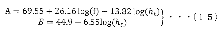
式(15)において、fは、伝搬する電波の周波数であり、htは、発射源Sのアンテナ高さである。 (15), f is the frequency of the propagating radio wave and ht is the height of the source S antenna.
電波の伝搬環境が開放地である場合(曲線k2)、a(hm)およびCは、次式(16)によって表される。 When the radio wave propagation environment is an open ground (curve k2), a(h m ) and C are expressed by the following equation (16).

電波の伝搬環境が郊外である場合(曲線k3)、a(hm)およびCは、次式(17)によって表される。 When the radio wave propagation environment is in the suburbs (curve k3), a(h m ) and C are expressed by the following equation (17).

電波の伝搬環境が中小都市である場合(曲線k4)、a(hm)およびCは、次式(18)によって表される。 When the radio wave propagation environment is a medium-sized city (curve k4), a(h m ) and C are expressed by the following equation (18).

電波の伝搬環境が大都市である場合(曲線k5)、a(hm)およびCは、次式(19)によって表される。 When the radio wave propagation environment is a metropolitan area (curve k5), a(h m ) and C are expressed by the following equation (19).
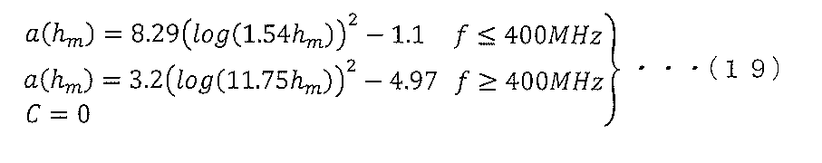
式(19)に示すように、大都市においては、周波数によってa(hm)が異なる。 As shown in Equation (19), a(h m ) differs depending on the frequency in large cities.
電力推定手段13は、式(14)~式(19)を保持しており、地形データが開放地に最も近いとき、式(14),(15),(16)によって曲線k2に示す電波伝搬特性を演算し、その演算した電波の伝搬モデルに基づいて位置[xr,yr,hr]における受信電力RSSI_ESTを推定する。 The power estimating means 13 holds the formulas (14) to (19), and when the terrain data is closest to the open ground, the radio wave propagation shown by the curve k2 by the formulas (14), (15), and (16) Characteristics are calculated, and the received power RSSI_EST at the position [x r , y r , hr ] is estimated based on the calculated radio wave propagation model.
また、電力推定手段13は、地形データが郊外に最も近いとき、式(14),(15),(17)によって曲線k3に示す電波の伝搬モデルを演算し、その演算した電波の伝搬モデルに基づいて位置[xr,yr,hr]における受信電力RSSI_ESTを推定する。 Further, when the terrain data is closest to the suburbs, the power estimating means 13 calculates the radio wave propagation model indicated by the curve k3 by the equations (14), (15), and (17), and uses the calculated radio wave propagation model as Estimate the received power RSSI_EST at location [x r , yr , hr ] based on.
更に、電力推定手段13は、地形データが中小都市に最も近いとき、式(14),(15),(18)によって曲線k4に示す電波の伝搬モデルを演算し、その演算した電波伝搬特性に基づいて位置[xr,yr,hr]における受信電力RSSI_ESTを推定する。 Furthermore, when the terrain data is closest to a small or medium-sized city, the power estimation means 13 calculates the radio wave propagation model indicated by the curve k4 by the equations (14), (15), and (18), and the calculated radio wave propagation characteristics are: Estimate the received power RSSI_EST at location [x r , yr , hr ] based on.
更に、推定手段17は、地形データが大都市に最も近いとき、式(14),(15),(19)によって曲線k5に示す電波の伝搬モデルを演算し、その演算した電波の伝搬モデルに基づいて位置[xr,yr,hr]における受信電力RSSI_ESTを推定する。 Furthermore, when the terrain data is closest to a large city, the estimation means 17 computes the radio wave propagation model indicated by the curve k5 using equations (14), (15), and (19), and uses the computed radio wave propagation model as Estimate the received power RSSI_EST at location [x r , yr , hr ] based on.
図17は、この発明の実施の形態による端末装置2の概略図である。図17を参照して、端末装置2は、電波品質推定装置1と、アンテナ21と、送受信手段22と、ホストシステム23と、GPS(Global Positioning System)受信機24とを備える。
FIG. 17 is a schematic diagram of a
送受信手段22は、ホストシステムから共用周波数fj(f1~fmのいずれか)を受け、その受けた共用周波数fjを有する電波をアンテナ21を介して受信し、電波を受信したときの受信電力RSSI_MESi_jを検出する。そして、送受信手段22は、その検出した受信電力RSSI_MESi_jをホストシステム23へ出力する。
Transmitting/receiving means 22 receives a shared frequency f j (any of f 1 to f m ) from the host system, receives radio waves having the received shared frequency f j via
また、送受信手段22は、アンテナ21を介して信号を受信し、その受信した受信信号をホストシステム23へ出力する。
Also, the transmitting/receiving means 22 receives a signal via the
更に、送受信手段22は、ホストシステム23から送信信号を受けると、その受けた送信信号をアンテナ21を介して送信する。
Furthermore, upon receiving a transmission signal from the
ホストシステム23は、共用周波数fjを送受信手段22へ出力する。また、ホストシステム23は、受信電力RSSI_MESi_jを送受信手段22から受け、端末装置2の位置を示す位置情報[xr,yr,hr]をGPS受信機24から受ける。そして、ホストシステム23は、共用周波数fj、位置[xr,yr,hr]および受信電力RSSI_MESi_jを相互に対応付けて電波品質推定装置1へ出力する。即ち、ホストシステム23は、測定データDを電波品質推定装置1へ出力する。また、ホストシステム23は、地図データを保持しており、位置[xr,yr,hr]および地図データに基づいて、端末装置2の周辺における電波の伝搬環境に関する環境情報INFOCIRを生成して電波品質推定装置1へ出力する。
The
ホストシステム23は、電波品質RSSI_Ratioを電波品質推定装置1から受け、その受けた電波品質RSSI_Ratioが基準値Std以内であるか否かを判定する。
The
ホストシステム23は、電波品質RSSI_Ratioが基準値Std以内であると判定したとき、送信信号を生成し、その生成した送信信号を送受信手段22へ出力する。
When the
一方、ホストシステム23は、電波品質RSSI_Ratioが基準値Std以内でないと判定したとき、送信信号を生成しない。つまり、ホストシステム23は、送信信号の送信を停止する。
On the other hand, when the
GPS受信機24は、GPSによって端末装置2の位置を示す位置情報[xr,yr,hr]を取得し、その取得した位置情報[xr,yr,hr]をホストシステム23へ出力する。
The
電波品質推定装置1は、測定データDをホストシステム23から受け、その受けた測定データDの共用周波数fj、位置[xr,yr,hr]および受信電力RSSI_MESi_jを対応表TBLに格納する。また、電波品質推定装置1は、環境情報INFOCIRをホストシステム23から受ける。
The radio wave
そして、電波品質推定装置1は、上述した方法によって電波品質RSSI_Ratioを推定し、その推定した電波品質RSSI_Ratioをホストシステム23へ出力する。
Then, radio wave
図18は、図17に示す端末装置2の動作を説明するためのフローチャートである。図18を参照して、端末装置2の動作が開始されると、端末装置2のホストシステム23は、上述した方法によって測定データDを収集し(ステップS21)、その収集した測定データDを電波品質推定装置1へ出力する。
FIG. 18 is a flow chart for explaining the operation of the
電波品質推定装置1の受付手段11は、ホストシステム23から測定データDを受け、その受けた測定データDを記憶手段12の対応表TBLに格納する。
The reception means 11 of the radio wave
その後、ホストシステム23は、上述した方法によって環境情報INFOCIRを取得し(ステップS22)、その取得した環境情報INFOCIRを電波品質推定装置1へ出力する。
After that, the
電波品質推定装置1の受付手段11は、ホストシステム23から環境情報INFOCIRを受け、その受けた環境情報INFOCIRを電力推定手段13へ出力する。
The reception means 11 of the radio wave
そして、ホストシステム23は、電波品質を推定すると判定すると(ステップS23)、GPS受信機24から受けた位置情報を、電波品質を推定する位置[xr,yr,hr]として取得し(ステップS24)、その取得した位置[xr,yr,hr]を電波品質推定装置1へ出力する。
Then, when the
そうすると、電波品質推定装置1は、図9に示すフローチャート(図10から図13に示すフローチャートを含む)に従って位置[xr,yr,hr]における電波品質RSSI_Ratioを推定し(ステップS25)、その推定した電波品質RSSI_Ratioをホストシステム23へ出力する。
Then, the radio wave
ホストシステム23は、電波品質RSSI_Ratioを電波品質推定装置1から受ける。そして、ホストシステム23は、電波品質RSSI_Ratioが基準値Std以内であるか否かを判定する(ステップS26)。
The
ステップS26において、電波品質RSSI_Ratioが基準値Std以内でないと判定されたとき、一連の動作は、ステップS23へ移行する。その後、ステップS26において、電波品質RSSI_Ratioが基準値Std以内であると判定されるまで、ステップS23~ステップS26が繰り返し実行される。 When it is determined in step S26 that the radio wave quality RSSI_Ratio is not within the standard value Std, the series of operations proceeds to step S23. Thereafter, steps S23 to S26 are repeatedly executed until it is determined in step S26 that the radio wave quality RSSI_Ratio is within the reference value Std.
そして、ステップS26において、電波品質RSSI_Ratioが基準値Std以内であると判定されると、ホストシステム23は、送受信手段22およびアンテナ21を介して無線通信を実行する(ステップS27)。
Then, when it is determined in step S26 that the radio wave quality RSSI_Ratio is within the reference value Std, the
その後、ホストシステム23は、無線通信を停止するか否かを判定する(ステップS28)。
After that, the
ステップS28において、無線通信を停止しないと判定されたとき、一連の動作は、ステップS23へ移行する。その後、ステップS28において、無線通信を停止すると判定されるまで、ステップS23~ステップS28が繰り返し実行される。そして、ステップS28において、無線通信を停止すると判定されると、端末装置2の動作が終了する。
When it is determined in step S28 not to stop wireless communication, the series of operations proceeds to step S23. Thereafter, steps S23 to S28 are repeatedly executed until it is determined in step S28 that the wireless communication should be stopped. Then, in step S28, when it is determined to stop the wireless communication, the operation of the
このように、端末装置2は、電波品質RSSI_Ratioを推定し、その推定した電波品質RSSI_Ratioが基準値Std以内であるとき、無線通信を実行する(ステップS25、ステップS26の“YES”およびステップS27参照)。
In this way, the
従って、電波品質が良い電波を用いて無線通信を行うことができる。電波品質RSSI_Ratioが基準値Std以内であるとき、推定した受信電力RSSI_ESTが測定した受信電力RSSI_MESにほぼ一致するからである。 Therefore, radio communication can be performed using radio waves with good radio wave quality. This is because the estimated received power RSSI_EST substantially matches the measured received power RSSI_MES when the radio wave quality RSSI_Ratio is within the reference value Std.
なお、図18に示すフローチャートにおいては、端末装置2が測定データDを収集すると説明したが、この発明の実施の形態においては、これに限らず、測定データDは、予め、電波品質推定装置1の記憶手段12に記憶されていてもよい。この場合、図18に示すステップS21は、実行されない。
In the flowchart shown in FIG. 18, it is explained that the
図19は、この発明の実施の形態によるデータ構造を示す図である。図19を参照して、この発明の実施の形態によるデータ構造D_STRは、周波数fと、位置[xr,yr,hr]と、受信電力RSSI_MESと、受信電力RSSI_ESTとを含む。 FIG. 19 is a diagram showing a data structure according to an embodiment of the invention. Referring to FIG. 19, the data structure D_STR according to the embodiment of the invention includes frequency f, position [xr, yr, hr], received power RSSI_MES and received power RSSI_EST .
周波数f、位置[xr,yr,hr]、受信電力RSSI_MESおよび受信電力RSSI_ESTは、相互に対応付けられる。 Frequency f, position [xr, yr, hr ], received power RSSI_MES and received power RSSI_EST are associated with each other.
位置[xr1_1,yr1_1,hr1_1],[xr2_1,yr2_1,hr2_1],・・・,[xrn_1,yrn_1,hrn_1]、受信電力RSSI_MES1_1,RSSI_MES2_1,・・・,RSS_MESIn_1および受信電力RSSI_EST1_1,RSSI_EST2_1,・・・,RSSI_ESTn_1は、周波数f1に対応付けられ、位置[xr1_2,yr1_2,hr1_2],[xr2_2,yr2_2,hr2_2],・・・,[xrn_2,yrn_2,hrn_2],受信電力RSSI_MES1_2,RSSI_MES2_2,・・・,RSSI_MESn_2および受信電力RSSI_EST1_2,RSSI_EST2_2,・・・,RSSI_ESTn_2は、周波数f2に対応付けられ、以下、同様にした、位置[xr1_m,yr1_m,hr1_m],[xr2_m,yr2_m,hr2_m],・・・,[xrn_m,yrn_m,hrn_m]、受信電力RSSI_MES1_m,RSSI_MES2_m,・・・,RSSI_MESn_mおよび受信電力RSSI_EST1_m,RSSI_EST2_m,・・・,RSSI_ESTn_mは、周波数fmに対応付けられる。 Positions [ xr1_1 , yr1_1 , hr1_1 ], [ xr2_1 , yr2_1 , hr2_1 ], ..., [ xrn_1 , yrn_1 , hr2_1 ], received power RSSI_MES1_1 , RSSI_MES2_1 , ..., RSS_MESI n_1 and received power RSSI_EST 1_1 , RSSI_EST 2_1 , . , [ xrn_2 , yrn_2 , hrn_2 ] , received power RSSI_MES1_2 , RSSI_MES2_2 , . Positions [ xr1_m , yr1_m , hr1_m ], [ xr2_m , yr2_m , hr2_m ], ..., [ xrn_m , yrn_m , hr2_m ], received power RSSI_MES 1_m , RSSI_MES 2_m , .
周波数fおよび位置[xr,yr,hr]は、品質推定手段14が周波数fおよび位置[xr,yr,hr]に対応する受信電力RSSI_MESおよび受信電力RSSI_ESTを検出するのに用いられる。
Frequency f and location [xr, yr, hr ] are used by
検出された受信電力RSSI_MESおよび受信電力RSSI_ESTは、品質推定手段14が受信電力の比RSSI_Ratioを推定するのに用いられる。 The detected received power RSSI_MES and received power RSSI_EST are used by the quality estimation means 14 to estimate the received power ratio RSSI_Ratio.
この発明の実施の形態においては、電波品質推定装置1の動作は、ソフトウェアによって実行されてもよい。この場合、電波品質推定装置1は、CPU(Central Processing Unit)、ROM(Read Only Memory)およびRAM(Random Access Memory)を備える。
In the embodiment of the present invention, the operation of radio wave
ROMは、図9に示すフローチャート(図10から図13に示すフローチャートを含む)からなるプログラムProg_Aを格納する。そして、CPUは、プログラムProg_AをROMから読み出し、その読み出したプログラムProg_Aを実行して電波品質RSSI_Ratioを推定する。RAMは、各種演算の結果を一時的に記憶する。 The ROM stores a program Prog_A consisting of the flowchart shown in FIG. 9 (including the flowcharts shown in FIGS. 10 to 13). The CPU then reads the program Prog_A from the ROM and executes the read program Prog_A to estimate the radio wave quality RSSI_Ratio. The RAM temporarily stores the results of various calculations.
また、プログラムProg_Aは、CD,DVD等の記録媒体に記録されて流通してもよい。この場合、CPUは、装着された記録媒体からプログラムProg_Aを読み出し、その読み出したプログラムProg_Aを実行して電波品質RSSI_Ratioを推定する。従って、プログラムProg_Aを記録したCD,DVD等の記録媒体は、コンピュータ(CPU)が読み取り可能な記録媒体である。 Also, the program Prog_A may be recorded on a recording medium such as a CD or DVD and distributed. In this case, the CPU reads the program Prog_A from the attached recording medium, executes the read program Prog_A, and estimates the radio wave quality RSSI_Ratio. Therefore, recording media such as CDs and DVDs on which the program Prog_A is recorded are computer (CPU) readable recording media.
また、この発明の実施の形態においては、端末装置2の動作は、ソフトウェアによって実行されてもよい。この場合、端末装置2は、CPU、ROMおよびRAMを備える。
Moreover, in the embodiment of the present invention, the operation of the
ROMは、図18に示すフローチャート(図9から図13に示すフローチャートを含む))からなるプログラムProg_Bを格納する。そして、CPUは、プログラムProg_BをROMから読み出して実行して電波品質RSSI_Ratioに基づいた無線通信を実行する。 The ROM stores a program Prog_B consisting of the flowchart shown in FIG. 18 (including the flowcharts shown in FIGS. 9 to 13). Then, the CPU reads the program Prog_B from the ROM and executes it to execute wireless communication based on the radio wave quality RSSI_Ratio.
また、プログラムProg_Bは、CD,DVD等の記録媒体に記録されて流通してもよい。この場合、CPUは、装着された記録媒体からプログラムProg_Bを読み出して実行して電波品質RSSI_Ratioに基づいた無線通信を実行する。従って、プログラムProg_Bを記録したCD,DVD等の記録媒体は、コンピュータ(CPU)が読み取り可能な記録媒体である。 Also, the program Prog_B may be recorded on a recording medium such as a CD or DVD and distributed. In this case, the CPU reads out the program Prog_B from the attached recording medium and executes it to perform wireless communication based on the radio wave quality RSSI_Ratio. Therefore, recording media such as CDs and DVDs on which the program Prog_B is recorded are computer (CPU) readable recording media.
上記においては、発射源Sの高さhrが20m以上である場合、電波の伝搬モデルMDL1に基づいて受信電力RSSI_ESTを推定し、発射源Sの高さhrが20mよりも低い場合、電波の伝搬モデルMDL2に基づいて受信電力RSSI_ESTを推定すると説明するとしたが、この発明の実施の形態においては、これに限らず、発射源Sの高さhrが建物の高さまたは平均高さ以上である場合、電波の伝搬モデルMDL1に基づいて受信電力RSSI_ESTを推定し、発射源Sの高さhrが建物の高さまたは平均高さよりも低い場合、電波の伝搬モデルMDL2に基づいて受信電力RSSI_ESTを推定するようにしてもよい。 In the above, when the height hr of the emission source S is 20 m or more, the received power RSSI_EST is estimated based on the radio wave propagation model MDL1 , and when the height hr of the emission source S is lower than 20 m, the radio wave Although it has been described that the received power RSSI_EST is estimated based on the propagation model MDL2 , the embodiment of the present invention is not limited to this, and the height hr of the emission source S is the height of a building or the average height or more. , the received power RSSI_EST is estimated based on the radio wave propagation model MDL1, and if the height h r of the emission source S is lower than the height of the building or the average height, the received power is estimated based on the radio wave propagation model MDL2 RSSI_EST may be estimated.
また、上記においては、対応表TBLは、周波数fを含むと説明したが、この発明の実施の形態においては、これに限らず、共用周波数が1個である場合、対応表TBLは、周波数fを含んでいなくてもよい。即ち、対応表TBLは、位置xri,yri,hri]および受信電力RSSI_MESiが相互に対応付けられた構成からなる。この場合、図9に示すフローチャートにおいては、ステップS1,S5において「周波数f」が削除されるとともに、ステップS2,S10,S11が削除される。従って、電波品質推定装置1は、n個の位置[xr1,yr1,hr1]~[xr1,yr1,hr1]の全てについて受信電力RSSI_EST1~RSSI_ESTnを推定するとともに受信電力の比RSSI_Ratio1~RSSI_Rationを推定する。
In the above description, the correspondence table TBL includes the frequency f, but the embodiment of the present invention is not limited to this. may not contain That is, the correspondence table TBL has a configuration in which positions x ri , y ri , h ri ] and received power RSSI_MES i are associated with each other. In this case, in the flowchart shown in FIG. 9, "frequency f" is deleted from steps S1 and S5, and steps S2, S10, and S11 are deleted. Therefore, the radio wave
更に、この発明の実施の形態によれば、SIR(Signal to Interference Ratio)が既知である場合、上述した方法によって推定された電波品質(=RSSI_Ratio)から無線通信のスループットを求め、その求めたスループットを評価するようにしてもよい。 Furthermore, according to the embodiment of the present invention, when the SIR (Signal to Interference Ratio) is known, the wireless communication throughput is obtained from the radio wave quality (=RSSI_Ratio) estimated by the above-described method, and the obtained throughput may be evaluated.
更に、この発明の実施の形態においては、上述した伝搬モデルMDL1,2および奥村-秦モデルに限らず、電波の伝搬環境によって異なる伝搬モデルであれば、どのような伝搬モデルを用いてもよい。 Further, in the embodiment of the present invention, any propagation model may be used as long as it differs depending on the propagation environment of radio waves, not limited to the propagation models MDL1, 2 and the Okumura-Hata model described above.
更に、上述したように、品質推定手段14がRSSI_EST/(RSSI_EST+RSSI_MES)を演算するのは、次の理由による。 Furthermore, as described above, the reason why the quality estimation means 14 calculates RSSI_EST/(RSSI_EST+RSSI_MES) is as follows.
受信電力RSSI_ESTは、上述したように、発射源Sの送信電力Ptおよび位置[xt,yt,ht]を用いて電波の伝搬モデルに基づいて推定される受信電力であり、その推定された受信電力RSSI_ESTを評価したいからである。 The received power RSSI_EST is the received power estimated based on the radio wave propagation model using the transmission power Pt and the position [ xt , yt, ht ] of the emission source S, as described above. This is because we want to evaluate the received power RSSI_EST received.
今回開示された実施の形態はすべての点で例示であって制限的なものではないと考えられるべきである。本発明の範囲は、上記した実施の形態の説明ではなくて特許請求の範囲によって示され、特許請求の範囲と均等の意味および範囲内でのすべての変更が含まれることが意図される。 It should be considered that the embodiments disclosed this time are illustrative in all respects and not restrictive. The scope of the present invention is indicated by the scope of the claims rather than the description of the above-described embodiments, and is intended to include all modifications within the scope and meaning equivalent to the scope of the claims.
この発明は、電波品質推定装置、それを備えた端末装置、コンピュータに実行させるためのプログラム、プログラムを記録したコンピュータ読み取り可能な記録媒体およびデータ構造に適用される。 INDUSTRIAL APPLICABILITY The present invention is applied to a radio wave quality estimation device, a terminal device equipped with the same, a program to be executed by a computer, a computer-readable recording medium storing the program, and a data structure.
1 電波品質推定装置、2 端末装置、11 受付手段、13 電力推定手段、14 品質推定手段、21 アンテナ、22 送受信手段23 ホストシステム、24 GPS受信機。
1 radio wave
Claims (14)
3次元空間において測定された発射源からの電波の受信電力である第1の受信電力と、前記第1の受信電力が測定された位置を示す位置情報とを対応付けて記憶する記憶手段と、
電波品質を推定する位置が入力されると、その入力された位置における受信電力を電波の伝搬モデルに基づいて推定する電力推定手段と、
前記電波品質を推定する位置が入力されると、その入力された位置に対応する第1の受信電力を前記記憶手段から読み出し、その読み出した第1の受信電力と前記電力推定手段によって推定された第2の受信電力との和に対する前記第2の受信電力の比を電波品質として推定する品質推定手段とを備える電波品質推定装置。 A radio wave quality estimation device for estimating the quality of a radio wave having a shared frequency shared by a terminal device for radio communication among a plurality of frequencies used for radio communication in a radio wave quality estimation target area,
storage means for storing a first received power, which is the received power of a radio wave from a radiation source measured in a three-dimensional space, in association with position information indicating a position where the first received power is measured;
power estimating means for estimating, when a position for estimating radio wave quality is input, the received power at the input position based on a radio wave propagation model;
When the position for estimating the radio wave quality is input, the first received power corresponding to the input position is read from the storage means, and the read first received power and the power estimation means estimate the received power. A radio wave quality estimating device comprising quality estimating means for estimating a ratio of the second received power to the sum of the second received power as radio wave quality.
前記電力推定手段は、前記電波品質を推定する位置および前記共用周波数を用いて、電波の伝搬モデルに基づいて前記第2の受信電力を推定し、
前記品質推定手段は、前記電波品質を推定する位置および前記共用周波数が入力されると、前記電波品質を推定する位置および前記共用周波数に対応付けられた前記第1の受信電力を前記記憶手段から読み出し、その読み出した第1の受信電力と前記電力推定手段によって推定された第2の受信電力とに基づいて前記電波品質を推定する、請求項1から請求項5のいずれか1項に記載の電波品質推定装置。 the storage means associates and stores the shared frequency with the first received power and the position information;
The power estimating means estimates the second received power based on a radio wave propagation model using the position for estimating the radio wave quality and the shared frequency,
When the position for estimating radio wave quality and the shared frequency are input, the quality estimating means stores the first received power associated with the position for estimating radio wave quality and the shared frequency from the storage means. 6. The radio wave quality according to any one of claims 1 to 5, wherein said radio wave quality is read out and said radio wave quality is estimated based on the read out first received power and said second received power estimated by said power estimating means. Radio wave quality estimation device.
前記電波品質推定装置によって推定された電波品質が基準値以内であるとき、無線通信を行う通信手段とを備える端末装置。 A radio wave quality estimation device according to any one of claims 1 to 6;
and communication means for performing wireless communication when the radio wave quality estimated by the radio wave quality estimation device is within a reference value.
電力推定手段が、電波品質を推定する位置が入力されると、その入力された位置における受信電力を電波の伝搬モデルに基づいて推定する第1のステップと、
品質推定手段が、前記電波品質を推定する位置が入力されると、3次元空間において測定された発射源からの電波の受信電力である第1の受信電力と前記第1の受信電力が測定された位置を示す位置情報とを対応付けて記憶する記憶手段から、前記入力された位置に対応する第1の受信電力を読み出し、その読み出した第1の受信電力と前記第1のステップにおいて推定された第2の受信電力との和に対する前記第2の受信電力の比を電波品質として推定する第2のステップとをコンピュータに実行させるためのプログラム。 A program for causing a computer to estimate the quality of a radio wave having a shared frequency shared by a terminal device for wireless communication among a plurality of frequencies used for wireless communication in a target area for estimating the quality of the radio wave,
a first step of estimating the received power at the input position based on a radio wave propagation model, when the position for estimating the radio wave quality is input by the power estimating means;
When the position for estimating the radio wave quality is input to the quality estimating means, the first received power, which is the received power of the radio wave from the emission source measured in the three-dimensional space, and the first received power are measured. The first received power corresponding to the input position is read out from the storage means for storing in association with the position information indicating the position, and the read first received power is estimated in the first step. A program for causing a computer to execute a second step of estimating a ratio of said second received power to a sum of said second received power as radio wave quality.
前記電力推定手段は、前記第1のステップにおいて、前記電波品質を推定する位置および前記共用周波数を用いて、電波の伝搬モデルに基づいて前記第2の受信電力を推定し、
前記品質推定手段は、前記第2のステップにおいて、前記電波品質を推定する位置および前記共用周波数が入力されると、前記電波品質を推定する位置および前記共用周波数に対応付けられた前記第1の受信電力を前記記憶手段から読み出し、その読み出した第1の受信電力と前記第1のステップにおいて推定された第2の受信電力とに基づいて前記電波品質を推定する、請求項8から請求項12のいずれか1項に記載のコンピュータに実行させるためのプログラム。 the storage means associates and stores the shared frequency with the first received power and the position information;
wherein, in the first step, the power estimating means estimates the second received power based on a radio wave propagation model using the position for estimating the radio wave quality and the shared frequency;
When the position for estimating radio wave quality and the shared frequency are input in the second step, the quality estimating means performs the first 8 to 12, wherein the received power is read from the storage means, and the radio wave quality is estimated based on the read first received power and the second received power estimated in the first step. A program to be executed by the computer according to any one of the above.
Priority Applications (1)
| Application Number | Priority Date | Filing Date | Title |
|---|---|---|---|
| JP2018094993A JP7154533B2 (en) | 2018-05-17 | 2018-05-17 | A radio wave quality estimation device, a terminal device equipped with the same, a program to be executed by a computer, and a computer-readable recording medium recording the program |
Applications Claiming Priority (1)
| Application Number | Priority Date | Filing Date | Title |
|---|---|---|---|
| JP2018094993A JP7154533B2 (en) | 2018-05-17 | 2018-05-17 | A radio wave quality estimation device, a terminal device equipped with the same, a program to be executed by a computer, and a computer-readable recording medium recording the program |
Publications (2)
| Publication Number | Publication Date |
|---|---|
| JP2019201333A JP2019201333A (en) | 2019-11-21 |
| JP7154533B2 true JP7154533B2 (en) | 2022-10-18 |
Family
ID=68612357
Family Applications (1)
| Application Number | Title | Priority Date | Filing Date |
|---|---|---|---|
| JP2018094993A Active JP7154533B2 (en) | 2018-05-17 | 2018-05-17 | A radio wave quality estimation device, a terminal device equipped with the same, a program to be executed by a computer, and a computer-readable recording medium recording the program |
Country Status (1)
| Country | Link |
|---|---|
| JP (1) | JP7154533B2 (en) |
Families Citing this family (1)
| Publication number | Priority date | Publication date | Assignee | Title |
|---|---|---|---|---|
| JP7605641B2 (en) * | 2021-01-26 | 2024-12-24 | 東日本旅客鉄道株式会社 | Method for estimating distribution of radio wave intensity received by wireless base station and method for redesigning antenna |
Citations (3)
| Publication number | Priority date | Publication date | Assignee | Title |
|---|---|---|---|---|
| WO2010122731A1 (en) | 2009-04-21 | 2010-10-28 | 日本電気株式会社 | Radio wave propagation characteristic estimation apparatus, method, and computer program |
| JP2014045285A (en) | 2012-08-24 | 2014-03-13 | Kddi Corp | Radio wave propagation height pattern characteristic estimator |
| WO2015159411A1 (en) | 2014-04-17 | 2015-10-22 | 富士通株式会社 | Frequency allocation apparatus, frequency allocation method, and wireless communication system |
-
2018
- 2018-05-17 JP JP2018094993A patent/JP7154533B2/en active Active
Patent Citations (3)
| Publication number | Priority date | Publication date | Assignee | Title |
|---|---|---|---|---|
| WO2010122731A1 (en) | 2009-04-21 | 2010-10-28 | 日本電気株式会社 | Radio wave propagation characteristic estimation apparatus, method, and computer program |
| JP2014045285A (en) | 2012-08-24 | 2014-03-13 | Kddi Corp | Radio wave propagation height pattern characteristic estimator |
| WO2015159411A1 (en) | 2014-04-17 | 2015-10-22 | 富士通株式会社 | Frequency allocation apparatus, frequency allocation method, and wireless communication system |
Non-Patent Citations (1)
| Title |
|---|
| Huawei, HiSilicon,Consideration on channel model for LTE Aerial[online],3GPP TSG RAN WG1 #89 R1- 1709291,Internet<URL:http://www.3gpp.org/ftp/tsg_ran/WG1_RL1/TSGR1_89/Docs/R1-1709291.zip>,2017年05月19日 |
Also Published As
| Publication number | Publication date |
|---|---|
| JP2019201333A (en) | 2019-11-21 |
Similar Documents
| Publication | Publication Date | Title |
|---|---|---|
| US20190219688A1 (en) | Environment perception method and base station | |
| CN113965874B (en) | Wave beam forming signal sending method and base station equipment | |
| EP3591412B1 (en) | Airborne system and method for the characterisation and measurement of radiating systems or antennas | |
| CN106332110B (en) | The prediction technique of 5G millimeter wave network signal intensity urban agglomeration | |
| US20170338901A1 (en) | Method for predicting indoor three-dimensional space signal field strength using an outdoor-to-indoor propagation model | |
| US20190253900A1 (en) | Method and device for communications in millimeter-wave networks | |
| CN114079866B (en) | Signal transmission method, equipment and device | |
| EP2530862A1 (en) | System and method for allocating jamming energy based on three-dimensional geolocation of emitters | |
| CN115085839B (en) | Unmanned aerial vehicle mountain terahertz channel modeling method based on ray tracing | |
| US20210036792A1 (en) | Real-time propagation analysis for communications systems | |
| Zhu et al. | A general altitude-dependent path loss model for UAV-to-ground millimeter-wave communications | |
| Piazzi et al. | Achievable accuracy of site-specific path-loss predictions in residential environments | |
| US20250005856A1 (en) | Metasurface design and placement | |
| JP7154533B2 (en) | A radio wave quality estimation device, a terminal device equipped with the same, a program to be executed by a computer, and a computer-readable recording medium recording the program | |
| Tang et al. | Study on RSS/AOA hybrid localization in life detection in huge disaster situation | |
| Dimitriou et al. | Architectural features and urban propagation | |
| Chebil et al. | Comparison of empirical propagation path loss models for mobile communications in the suburban area of Kuala Lumpur | |
| Yamada et al. | Observation data and 3D map-based radio environment estimation for drone wireless communications | |
| Militaru et al. | 4G/LTE Issues of Low Altitude UAV Flying Systems | |
| Saito et al. | Vertical and horizontal building entry loss measurement in 4.9 GHz band by unmanned aerial vehicle | |
| Afape et al. | Path loss modelling of mmwave outdoor propagation for 5G mobile systems at 28, 38, 60, and 73 GHz in four Nigerian cities | |
| Solomitckii | Evaluation of mmWave 5G performance by advanced ray tracing techniques | |
| Saito et al. | 4.9 GHz band outdoor to indoor propagation loss analysis in high building environment using unmanned aerial vehicle | |
| CN118174808A (en) | An air-to-air channel modeling method and system for UAV communication scenarios | |
| CN117440507A (en) | A positioning method, device, equipment and storage medium |
Legal Events
| Date | Code | Title | Description |
|---|---|---|---|
| A80 | Written request to apply exceptions to lack of novelty of invention |
Free format text: JAPANESE INTERMEDIATE CODE: A80 Effective date: 20180614 |
|
| A621 | Written request for application examination |
Free format text: JAPANESE INTERMEDIATE CODE: A621 Effective date: 20210329 |
|
| A977 | Report on retrieval |
Free format text: JAPANESE INTERMEDIATE CODE: A971007 Effective date: 20220316 |
|
| A131 | Notification of reasons for refusal |
Free format text: JAPANESE INTERMEDIATE CODE: A131 Effective date: 20220426 |
|
| A521 | Request for written amendment filed |
Free format text: JAPANESE INTERMEDIATE CODE: A523 Effective date: 20220512 |
|
| TRDD | Decision of grant or rejection written | ||
| A01 | Written decision to grant a patent or to grant a registration (utility model) |
Free format text: JAPANESE INTERMEDIATE CODE: A01 Effective date: 20220927 |
|
| A61 | First payment of annual fees (during grant procedure) |
Free format text: JAPANESE INTERMEDIATE CODE: A61 Effective date: 20220927 |
|
| R150 | Certificate of patent or registration of utility model |
Ref document number: 7154533 Country of ref document: JP Free format text: JAPANESE INTERMEDIATE CODE: R150 |
|
| R250 | Receipt of annual fees |
Free format text: JAPANESE INTERMEDIATE CODE: R250 |