JP7148774B2 - Drilling sensation imparting device, joint structure, drilling sensation imparting method, drilling sensation imparting program, skill evaluation device, skill evaluation method, and skill evaluation program - Google Patents
Drilling sensation imparting device, joint structure, drilling sensation imparting method, drilling sensation imparting program, skill evaluation device, skill evaluation method, and skill evaluation program Download PDFInfo
- Publication number
- JP7148774B2 JP7148774B2 JP2018024902A JP2018024902A JP7148774B2 JP 7148774 B2 JP7148774 B2 JP 7148774B2 JP 2018024902 A JP2018024902 A JP 2018024902A JP 2018024902 A JP2018024902 A JP 2018024902A JP 7148774 B2 JP7148774 B2 JP 7148774B2
- Authority
- JP
- Japan
- Prior art keywords
- excavation
- force
- feeling
- operator
- excavated
- Prior art date
- Legal status (The legal status is an assumption and is not a legal conclusion. Google has not performed a legal analysis and makes no representation as to the accuracy of the status listed.)
- Active
Links
Images


Landscapes
- Earth Drilling (AREA)
Description
特許法第30条第2項適用 第60回自動制御連合講演会、SuI1-4、公益社団法人計測自動制御学会、平成29年11月12日 http://www.sice.or.jp/rengo60/Application of Article 30,
本発明は、掘削感付与装置、ジョイント構造物、掘削感付与方法、及び掘削感付与プログラム、並びに技能評価装置、技能評価方法、及び技能評価プログラムに関する。 The present invention relates to an excavation sensation imparting device, a joint structure, an excavation sensation imparting method, an excavation sensation imparting program, a skill evaluation device, a skill evaluation method, and a skill evaluation program.
近年、医療技術の向上や医療機器の発展に伴い、手術者等の技能向上や特殊技能の獲得を目的として、力覚提示装置等を用いたトレーニングシミュレータの開発が進められている。 BACKGROUND ART In recent years, with the improvement of medical technology and the development of medical equipment, training simulators using haptic presentation devices and the like have been developed for the purpose of improving the skills of surgeons and acquiring special skills.
このような力覚提示装置としては、例えば、皮膚や臓器等の軟性物体への繊細な接触動作に対して臨場感のある人工現実感を実現するものが提案されており、操作者へ力覚を提示する操作端や該操作端に運動を伝える駆動機構を軽量化することにより応答性の向上を図っている。しかし、操作端や駆動機構を軽量化して応答性を高めると、力覚提示装置の剛性が低下するおそれがあるが、皮膚や臓器等の軟性物体への繊細な接触動作では、操作力が小さいため、力覚提示装置の剛性低下の影響は少ないと考えられる。 As such a haptic presentation device, for example, a device has been proposed that realizes an artificial reality with a sense of realism in response to a delicate contact action on a soft object such as the skin or an organ. The responsiveness is improved by reducing the weight of the manipulator that presents and the drive mechanism that transmits motion to the manipulator. However, increasing the responsiveness by reducing the weight of the operation end and drive mechanism may reduce the rigidity of the haptic device. Therefore, it is considered that the influence of the decrease in rigidity of the haptic device is small.
一方、骨や歯等の硬性物体に対するトレーニングシミュレータとしての力覚提示装置も提案されている。例えば、操作者が握って動かすことができるメスやドリル等の模擬手術道具を備え、複数のモダリティの画像から手術対象部分の各組織を含む画像を合成する画像合成手段と、合成した画像を3次元表示する3次元画像表示手段と、模擬手術道具をその動きを含めて画像に重畳表示する重畳表示手段と、重畳表示手段において模擬手術道具が組織に接したとき、両者の硬度に対応する音を発生し、模擬手術道具に反発力を与える人工現実感創出手段を有する手術シミュレーションシステムが提案されている(例えば、特許文献1参照)。
また、手術を実施する際に外科医を支援するための外科用ナビゲーションシステムに関し、骨の切除シミュレーションについて記載されている(例えば、特許文献2参照)。
On the other hand, force sense presentation devices have also been proposed as training simulators for hard objects such as bones and teeth. For example, an image synthesizing means for synthesizing an image including each tissue of the surgical target portion from images of a plurality of modalities, and synthesizing the synthesized image into three. A three-dimensional image display means for dimensional display, a superimposed display means for superimposing and displaying the simulated surgical tool including its movement on the image, and a sound corresponding to the hardness of both when the simulated surgical tool comes into contact with the tissue in the superimposed display means. A surgical simulation system has been proposed that has an artificial reality creation means that generates a repulsive force on a simulated surgical tool (see, for example, Patent Document 1).
Also, a surgical navigation system for assisting a surgeon in performing surgery is described for bone resection simulation (see, for example, US Pat.
しかしながら、上述した先行技術文献には、骨や歯等の硬性物体に対する臨場感のある人工現実感を与える力覚提示技術については開示されていない。また、骨や歯等の硬性物体への骨切削術及び骨切除術は、強い衝撃力を与える操作であり、その操作に対して臨場感のある人工現実感を与える力覚提示装置には、高い剛性と共に、操作端の運動の高い応答性も求められるが、高い剛性と高い応答性とを兼ね備えた、硬性物体に対する臨場感のある人工現実感を与える力覚提示装置は未だ提供されていない。
更に、骨や歯等の硬性物体に対する骨切削術及び骨切除術を行う操作者は、骨や歯への過剰な負荷により骨や歯の亀裂や骨折、穿孔を生じさせない適切な掘削力と、神経や血管、臓器が近くに存在することが多いため、これらを傷付けることなく安全に手術を行うことができる高度な熟練技能の習得が求められている。
However, the above-mentioned prior art documents do not disclose a haptic presentation technology that gives realistic artificial reality to hard objects such as bones and teeth. In addition, osteotomy and osteotomy for hard objects such as bones and teeth are operations that apply a strong impact force. In addition to high rigidity, high responsiveness in movement of the operating end is also required, but there has not yet been provided a haptic presentation device that has both high rigidity and high responsiveness and gives realistic artificial reality to hard objects. .
Furthermore, an operator who performs osteotomy and osteotomies on hard objects such as bones and teeth must have an appropriate excavation force that does not cause cracks, fractures, and perforations in bones and teeth due to excessive load on the bones and teeth, Nerves, blood vessels, and organs are often located nearby, so there is a need to acquire high-level skills to safely perform surgery without damaging them.
本発明は、従来における前述の諸問題のうち少なくともいずれかを解決し、以下の目的を達成することを課題とする。即ち、本発明は、高い剛性及び高い応答性能を兼ね備えた、硬性物体に対する臨場感のある人工現実感を与える掘削感付与装置、ジョイント構造物、掘削感付与方法、及び掘削感付与プログラムを提供することを目的とする。
また、本発明は、操作者の技能を適正に評価でき、安全かつ確実に熟練技能を習得することができる技能評価装置、技能評価方法、及び技能評価プログラムを提供することを目的とする。
SUMMARY OF THE INVENTION An object of the present invention is to solve at least one of the above-described conventional problems and to achieve the following objects. That is, the present invention provides an excavation sensation imparting device, a joint structure, an excavation sensation imparting method, and an excavation sensation imparting program that imparts realistic artificial reality to a hard object with both high rigidity and high response performance. for the purpose.
Another object of the present invention is to provide a skill evaluation device, a skill evaluation method, and a skill evaluation program capable of properly evaluating the skill of an operator and safely and reliably acquiring expert skills.
本発明の掘削感付与装置は、想定された掘削対象に対する模擬の掘削操作が操作者により行われる被掘削操作部を有する掘削操作手段と、前記被掘削操作部に印加された掘削力に応じて、前記掘削操作手段を介して前記操作者に対して人工的な掘削感を付与する掘削感付与手段と、を有する。
本発明の掘削感付与装置によると、掘削操作手段と掘削感付与手段を有することにより、硬性物体に対する臨場感のある人工現実感を与えることができ、口腔外科手術や整形外科手術などにおける骨や歯等の硬性物体の切削や切除のトレーニングシミュレータとして好適である。
An excavation feeling imparting apparatus of the present invention comprises an excavation operation means having an excavation operation section in which an operator performs a simulated excavation operation on an assumed excavation object, and an excavation operation section that responds to an excavation force applied to the excavation operation section. and excavation feeling imparting means for imparting an artificial excavation feeling to the operator through the excavation operation means.
According to the excavation sensation imparting device of the present invention, by having the excavation operation means and the excavation sensation imparting means, it is possible to impart realistic artificial reality to a hard object. It is suitable as a training simulator for cutting and excision of hard objects such as teeth.
本発明の掘削感付与方法は、想定された掘削対象に対する模擬の掘削操作が被掘削操作部に対して操作者により行われる掘削操作工程と、前記掘削操作工程で前記被掘削操作部に印加された掘削力に応じて、前記掘削操作工程を介して前記操作者に対して人工的な掘削感を付与する掘削感付与工程と、を含む。
本発明の掘削感付与方法によると、掘削操作工程と掘削感付与工程を含むことにより、硬性物体に対する臨場感のある人工現実感を与えることができ、口腔外科手術や整形外科手術などにおける骨や歯等の硬性物体の切削や切除のトレーニングを好適に行うことができる。
The method for imparting an excavation feeling of the present invention includes an excavation operation step in which a simulated excavation operation for an assumed excavation object is performed on an excavation operation portion by an operator, and an excavation operation step in which an excavation operation portion is impressed in the excavation operation step. and a digging feeling imparting step of imparting an artificial digging feeling to the operator through the digging operation step according to the excavating force applied.
According to the excavation sensation imparting method of the present invention, by including the excavation operation step and the excavation sensation imparting step, it is possible to impart realistic artificial reality to a hard object. Training for cutting and resecting hard objects such as teeth can be suitably performed.
本発明の掘削感付与プログラムは、操作者により行われる想定された掘削対象に対する模擬の掘削操作を、被掘削操作部を有する掘削操作手段を介して受け付け、前記被掘削操作部に印加された掘削力に応じて、前記掘削操作手段を介して前記操作者に対して人工的な掘削感を付与する、処理をコンピュータに実行させる。
本発明の掘削感付与プログラムによると、硬性物体に対する臨場感のある人工現実感を与えることができ、口腔外科手術や整形外科手術などにおける骨や歯等の硬性物体の切削や切除のトレーニングを好適に行うことができる。
A program for imparting a feeling of excavation according to the present invention receives a simulated excavation operation for an assumed excavation target performed by an operator via excavation operation means having an excavation operation unit, and excavation is applied to the excavation operation unit. A computer is caused to execute a process of giving an artificial excavation feeling to the operator through the excavation operation means according to the force.
According to the excavation feeling imparting program of the present invention, it is possible to impart realistic artificial reality to hard objects, and it is suitable for training in cutting and excision of hard objects such as bones and teeth in oral surgery and orthopedic surgery. can be done.
本発明のジョイント構造物は、ボールリテーナと、前記ボールリテーナを押圧しつつ前記ボールリテーナの回動を案内する回動案内部材と、前記ボールリテーナに接続される接続部と、前記回動案内部材により案内された前記ボールリテーナの回動方向と直交する方向に前記ボールリテーナを回動可能にするようにして軸支された軸支部とを有する棒状部材と、を有する。
本発明のジョイント構造物は、ボールリテーナと、回動案内部材と、棒状部材とを有する。ボールリテーナは、回動可能な複数のボールを表面に配置した構造を有しており、ボールリテーナはその表面の複数のボールと回動案内部材との点接触によって支持されている。これにより、ボールリテーナと回動案内部材とが密着し、バックラッシを低減させることによって、滑らかな3軸の回転操作を行うことができ、ガタツキを確実に防止できる。
The joint structure of the present invention includes a ball retainer, a rotation guide member for guiding rotation of the ball retainer while pressing the ball retainer, a connecting portion connected to the ball retainer, and the rotation guide member. a rod-like member having a shaft support portion that is pivotally supported so as to allow the ball retainer to rotate in a direction perpendicular to the direction of rotation of the ball retainer guided by the ball retainer.
A joint structure of the present invention has a ball retainer, a rotation guide member, and a rod-shaped member. The ball retainer has a structure in which a plurality of rotatable balls are arranged on its surface, and the ball retainer is supported by point contact between the plurality of balls on its surface and the rotation guide member. As a result, the ball retainer and the rotation guide member are brought into close contact with each other to reduce backlash, thereby enabling smooth rotation of the three axes and reliably preventing backlash.
本発明の技能評価装置は、想定された掘削対象に対する模擬の掘削操作が操作者により行われる被掘削操作部を有する掘削操作手段と、前記被掘削操作部に印加された掘削力に応じて、前記掘削操作手段を介して前記操作者に対して人工的な掘削感を付与する掘削感付与手段と、想定操作者における掘削力の大きさ及び印加方向の少なくともいずれかを予め記憶している基準データと比較して前記操作者の技能を評価する評価部と、を有する。
本発明の技能評価装置によると、掘削操作手段と掘削感付与手段と評価手段とを有することにより、操作者の技能を適正に評価でき、安全かつ確実に技能を習得することができるので、高度な熟練技能を伝承することができる。
The skill evaluation apparatus of the present invention comprises an excavation operation means having an excavation operation unit in which an operator performs a simulated excavation operation on an assumed excavation object; Excavation feeling imparting means for imparting an artificial excavation feeling to the operator through the excavation operation means, and a reference pre-stored at least one of the magnitude and application direction of the excavation force for the assumed operator. an evaluation unit for evaluating the operator's skill compared to the data.
According to the skill evaluation device of the present invention, by having the excavation operation means, the excavation feeling imparting means, and the evaluation means, the operator's skill can be properly evaluated, and the operator can learn the skill safely and reliably. skills can be passed on.
本発明の技能評価方法は、想定された掘削対象に対する模擬の掘削操作が被掘削操作部に対して操作者により行われる掘削操作工程と、前記被掘削操作部に印加された掘削力に応じて、前記掘削操作手段を介して前記操作者に対して人工的な掘削感を付与する掘削感付与工程と、想定操作者における掘削力の大きさ及び印加方向の少なくともいずれかを予め記憶している基準データと比較して前記操作者の技能を評価する評価工程と、を含む。
本発明の技能評価方法によると、掘削操作工程と掘削感付与工程と評価工程とを含むことにより、操作者の技能を適正に評価でき、安全かつ確実に技能を習得することができるので、高度な熟練技能を伝承することができる。
The skill evaluation method of the present invention includes an excavation operation step in which an operator performs a simulated excavation operation on an assumed excavation target on an excavated operation unit, and an excavation force applied to the excavated operation unit. and at least one of a digging feeling imparting step of imparting an artificial digging feeling to the operator via the digging operation means, and the magnitude and application direction of the digging force for the assumed operator are stored in advance. an evaluation step of evaluating the operator's skill compared to reference data.
According to the skill evaluation method of the present invention, by including the excavation operation process, the excavation feeling imparting process, and the evaluation process, the operator's skill can be properly evaluated, and the skill can be learned safely and reliably. skills can be passed on.
本発明の技能評価プログラムは、操作者により行われる想定された掘削対象に対する模擬の掘削操作を、被掘削操作部を有する掘削操作手段を介して受け付け、前記掘削操作手段により前記被掘削操作部に印加された掘削力に応じて、前記掘削操作手段を介して前記操作者に対して人工的な掘削感を付与し、想定操作者における掘削力の大きさ及び印加方向の少なくともいずれかを予め記憶している基準データと比較して前記操作者の技能を評価する処理をコンピュータに実行させる。
本発明の技能評価プログラムによると、操作者の技能を適正に評価でき、安全かつ確実に技能を習得することができるので、高度な熟練技能を伝承することができる。
The skill evaluation program of the present invention receives a simulated excavation operation for an assumed excavation target performed by an operator via an excavation operation means having an excavation operation unit, According to the applied excavation force, an artificial excavation feeling is given to the operator via the excavation operation means, and at least one of the magnitude and application direction of the excavation force for the assumed operator is stored in advance. A computer is caused to perform a process of evaluating the operator's skill in comparison with the reference data that is running.
According to the skill evaluation program of the present invention, the skill of the operator can be properly evaluated, and the skill can be learned safely and reliably, so that highly skilled skills can be handed down.
本発明によると、硬性物体に対する臨場感のある人工現実感を与えることができる掘削感付与装置、ジョイント構造物、掘削感付与方法、及び掘削感付与プログラムを提供することができる。
また、本発明によると、操作者の技能を適正に評価でき、安全かつ確実に技能を習得することができる技能評価装置、技能評価方法、及び技能評価プログラムを提供することができる。
According to the present invention, it is possible to provide an excavation sensation imparting device, a joint structure, an excavation sensation imparting method, and an excavation sensation imparting program capable of imparting realistic artificial reality to a hard object.
Moreover, according to the present invention, it is possible to provide a skill evaluation device, a skill evaluation method, and a skill evaluation program that can properly evaluate the skill of an operator and enable the skill to be learned safely and reliably.
(掘削感付与装置、掘削感付与方法、及び掘削感付与プログラム)
本発明の掘削感付与装置は、掘削操作手段と、掘削感付与手段とを有し、仮想空間表示手段及び支持手段を有することが好ましく、更に必要に応じてその他の手段を有する。
本発明の掘削感付与方法は、掘削操作工程と、掘削感付与工程とを含み、仮想空間表示工程及び支持工程を含むことが好ましく、更に必要に応じてその他の工程を含む。
本発明の掘削感付与プログラムは、操作者により行われる想定された掘削対象に対する模擬の掘削操作を、被掘削操作部を有する掘削操作手段を介して受け付け、前記被掘削操作部に印加された掘削力に応じて、掘削操作手段を介して操作者に対して人工的な掘削感を付与する、処理をコンピュータに実行させる。
(Drilling sensation imparting device, drilling sensation imparting method, and drilling sensation imparting program)
The excavation sensation imparting device of the present invention has excavation operation means and excavation sensation imparting means, preferably virtual space display means and support means, and further comprises other means as necessary.
The excavation feeling imparting method of the present invention includes an excavation operation step and an excavation sensation imparting step, preferably includes a virtual space display step and a supporting step, and further includes other steps as necessary.
A program for imparting a feeling of excavation according to the present invention receives a simulated excavation operation for an assumed excavation target performed by an operator via excavation operation means having an excavation operation unit, and excavation is applied to the excavation operation unit. The computer is caused to execute a process of giving an artificial excavation feeling to the operator via the excavation operation means in accordance with the force.
本発明の「掘削感付与装置」における掘削操作手段や掘削感付与手段等が行う制御は、本発明の「掘削感付与方法」を実施することと同義であるので、本発明の「掘削感付与装置」の説明を通じて本発明の「掘削感付与方法」の詳細についても明らかにする。また、本発明の「掘削感付与プログラム」は、ハードウェア資源としてのコンピュータ等を用いることにより、本発明の「掘削感付与装置」として実現させることから、本発明の「掘削感付与装置」の説明を通じて本発明の「掘削感付与プログラム」の詳細についても明らかにする。
本発明の掘削感付与方法は、本発明の掘削感付与装置により好適に実施することができ、掘削操作工程は掘削操作手段により行うことができ、掘削感付与工程は掘削感付与手段により行うことができ、仮想空間表示工程は仮想空間表示手段により行うことができ、支持工程は支持手段により行うことができ、その他の工程はその他の手段により行うことができる。
The control performed by the excavation operation means, the excavation sensation imparting means, etc. in the "excavation sensation imparting device" of the present invention is synonymous with carrying out the "excavation sensation imparting method" of the present invention. The details of the "excavation feeling imparting method" of the present invention will also be clarified through the explanation of the "apparatus". Further, since the "excavation feeling imparting program" of the present invention is realized as the "excavation feeling imparting device" of the present invention by using a computer or the like as hardware resources, the "excavating sensation imparting device" of the present invention can be realized. The details of the "excavation feeling imparting program" of the present invention will also be clarified through the explanation.
The excavation feeling imparting method of the present invention can be preferably carried out by the excavation sensation imparting device of the present invention, the excavation operation step can be carried out by the excavation operation means, and the excavation sensation imparting step can be carried out by the excavation sensation imparting means. The virtual space display step can be performed by the virtual space display means, the support step can be performed by the support means, and the other steps can be performed by other means.
<掘削操作工程及び掘削操作手段>
掘削操作工程は、想定された掘削対象に対する模擬の掘削操作が被掘削操作部に対して操作者により行われる工程であり、掘削操作手段により行われる。
<Excavation operation step and excavation operation means>
The excavation operation process is a process in which a simulated excavation operation for an assumed excavation target is performed by the operator on the excavated operation unit, and is performed by the excavation operation means.
<<掘削対象>>
以下、本発明における模擬の掘削操作の対象物として想定される対象物のことを「掘削対象」と称する。すなわち、以下の記載において「掘削対象に対し掘削力を印加する」ということは、想定された掘削対象に対し模擬の掘削力を印加する操作を意味する。
掘削対象としては、掘削可能な対象物であれば特に制限はなく、目的に応じて適宜選択することができる。
掘削とは、掘削対象に対して強い力を与えて掘削対象を掘ったり、削ったりすることを意味し、打撃や回転体の押し込みなどにより掘削対象を所望の形状に調整することも含む。
掘削対象としては、例えば、骨、歯、石、金属、木材、プラスチック、セラミックス、宝石などが挙げられる。
骨としては、例えば、頭蓋骨、顔面骨、脊椎骨、胸骨、肋骨、肩甲骨、鎖骨、上腕骨、前腕骨、手根骨、中手骨、指骨、骨盤、大腿骨、膝蓋骨、下腿骨、足根骨、中足骨、趾骨などが挙げられる。
歯としては、例えば、乳歯(乳中切歯、乳側切歯、乳犬歯、第一乳臼歯、第二乳臼歯)、永久歯(切歯、犬歯、小臼歯、大臼歯)などが挙げられる。
石としては、例えば、大理石、御影石、花崗岩、砂岩、石灰岩、安山岩、凝灰岩、粘板岩などが挙げられる。
金属としては、例えば、鉄、アルミニウム、銅、金、銀、マグネシウム、ニッケル、ステンレス鋼、チタン、亜鉛などが挙げられる。
木材としては、例えば、ヒノキ、ベイヒ、ヒバ、ベイヒバ、スギ、ベイスギ、カラマツ、アカマツ、エゾマツ、クリ、ケヤキ、サワラ、マキ、カシ、サクラ、モミ、ツガ、ベイツガなどが挙げられる。
プラスチックとしては、例えば、塩化ビニル、ポリ塩化ビニリデン、ポリビニルアルコール、ポリスチレン、スチレン・アクリロニトリル共重合体、スチレン・ブタジエン・アクリロニトリル共重合体、ポリエチレン、エチレン・酢酸ビニル共重合体、ポリプロピレン、ポリアセタール、アクリル、ポリメチルメタクリレート、変性アクリル、ポリカーボネートポリアミド、ポリウレタン、ポリブチレンテレフタレート、ポリスルホン、ポリフェニレンスルファイド、ポリエーテルエーテルケトン、ポリイミド、ポリエーテルイミドなどが挙げられる。
セラミックスとしては、例えば、アルミナ、ジルコニア、窒化珪素、窒化アルミ、炭化珪素、チタン酸バリウム、ハイドロキシアパタイト、フェライト、酸化アルミニウム、酸化亜鉛などが挙げられる。
宝石としては、例えば、エメラルド、オパール、水晶、ダイヤモンド、トルコ石、真珠などが挙げられる。
<<Drilling target>>
Hereinafter, an object assumed as an object for a simulated excavation operation in the present invention will be referred to as an "excavation object". That is, in the following description, "applying an excavation force to an excavation target" means an operation of applying a simulated excavation force to an assumed excavation target.
The object to be excavated is not particularly limited as long as it is an object that can be excavated, and can be appropriately selected according to the purpose.
Excavation means digging or scraping an object to be excavated by applying a strong force to the object to be excavated, and includes adjusting the object to be excavated into a desired shape by hitting, pressing a rotating body, or the like.
Excavation targets include, for example, bones, teeth, stones, metals, wood, plastics, ceramics, gems, and the like.
Bones include, for example, the skull, facial bones, vertebrae, sternum, ribs, scapula, clavicle, humerus, forearm, carpal, metacarpal, phalanges, pelvis, femur, patella, lower leg, and tarsus. Examples include bones, metatarsal bones, and toe bones.
Teeth include, for example, deciduous teeth (deciduous central incisors, deciduous lateral incisors, deciduous canines, first deciduous molars, second deciduous molars), permanent teeth (incisors, canines, premolars, molars) and the like.
Stones include, for example, marble, granite, granite, sandstone, limestone, andesite, tuff, and slate.
Examples of metals include iron, aluminum, copper, gold, silver, magnesium, nickel, stainless steel, titanium, and zinc.
Examples of wood include cypress, cypress, cypress, cedar, Japanese cedar, larch, red pine, Ezo spruce, chestnut, zelkova, Japanese sawara, Japanese maki, oak, cherry, fir, hemlock, and hemlock.
Examples of plastics include vinyl chloride, polyvinylidene chloride, polyvinyl alcohol, polystyrene, styrene/acrylonitrile copolymer, styrene/butadiene/acrylonitrile copolymer, polyethylene, ethylene/vinyl acetate copolymer, polypropylene, polyacetal, acrylic, polymethyl methacrylate, modified acrylic, polycarbonate polyamide, polyurethane, polybutylene terephthalate, polysulfone, polyphenylene sulfide, polyetheretherketone, polyimide, polyetherimide and the like.
Examples of ceramics include alumina, zirconia, silicon nitride, aluminum nitride, silicon carbide, barium titanate, hydroxyapatite, ferrite, aluminum oxide, and zinc oxide.
Gems include, for example, emeralds, opals, crystals, diamonds, turquoises, pearls, and the like.
<<操作者>>
操作者は、掘削対象に対する模擬の掘削操作を被掘削操作部に対して行う者であり、例えば、医学部や歯学部の学生、医者、歯医者、歯科技工士、大工、木材加工職人、石工、彫刻家、金属加工職人、旋盤工、金型職人、宝石加工職人などが挙げられる。
<<operator>>
An operator is a person who performs a simulated excavation operation on an excavation target, and is, for example, a medical or dental student, a doctor, a dentist, a dental technician, a carpenter, a wood worker, a mason, or a sculptor. , metal workers, lathe workers, mold workers, and jewelers.
<<被掘削操作部>>
被掘削操作部は、掘削対象に対する模擬の掘削操作が操作者により行われる箇所であり、例えば、被打撃部や被回動乃至回転部などである。また、掘削対象に応じて大きさ、形状、構造などを適宜選択・交換することができる。
<<Excavating Operation Part>>
The excavation operation part is a part where the operator performs a simulated excavation operation on the excavation object, and is, for example, a hit part, a rotated or a rotating part, and the like. In addition, the size, shape, structure, etc. can be appropriately selected and exchanged according to the excavation target.
-被打撃部-
被打撃部は、打撃手段により打撃されることにより、掘削力が印加される部分であり、打撃面などが該当する。
打撃とは、掘削対象を強く打つこと、即ち、掘削対象の打撃される面と打撃手段とが強く当たることを意味し、人が実行する場合にかぎられず、機械やロボットが実行する場合も含まれる。
打撃力とは、掘削対象を打撃する力を意味する。
-Striking part-
The hit portion is a portion to which an excavation force is applied by being hit by the hitting means, and corresponds to a hitting surface or the like.
Striking means hitting the object to be excavated hard, that is, the surface of the object to be excavated hits hard against the striking means. be
The impact force means the force with which the object to be excavated is impacted.
被打撃部の大きさ、形状、及び構造としては、特に制限はなく、掘削対象の大きさ、形状、及び構造に応じて適宜選択することができる。
被打撃部の材質としては、掘削対象を掘削することができれば特に制限はなく、目的に応じて適宜選択することができ、例えば、金属、樹脂などが挙げられる。
金属としては、例えば、アルミニウム、鉄、銅、ステンレススチール、クロム-ニッケル合金、チタン合金、などが挙げられる。
樹脂としては、例えば、ポリエチレン、ポリカーボネート、アクリロニトリル-ブタジエン-スチレン(ABS)共重合体、繊維強化プラスチック(FRP)、テフロン(登録商標)などが挙げられる。
The size, shape, and structure of the hit portion are not particularly limited, and can be appropriately selected according to the size, shape, and structure of the object to be excavated.
The material of the impacted portion is not particularly limited as long as the object to be excavated can be excavated, and can be appropriately selected according to the purpose. Examples thereof include metals and resins.
Examples of metals include aluminum, iron, copper, stainless steel, chromium-nickel alloys, titanium alloys, and the like.
Examples of resins include polyethylene, polycarbonate, acrylonitrile-butadiene-styrene (ABS) copolymer, fiber reinforced plastic (FRP), and Teflon (registered trademark).
被打撃部としては、具体的には、ノミ、骨ノミ、メス、カッター、釘、針等の打撃面が挙げられる。
打撃手段としては、例えば、金槌、骨マレット、ハンマー、斧、人の拳などが挙げられる。
Specific examples of the hit part include the hitting surfaces of chisels, bone chisels, scalpels, cutters, nails, needles, and the like.
Examples of striking means include hammers, bone mallets, hammers, axes, human fists, and the like.
-被回動乃至回転部-
被回動乃至回転部は、押圧されながら回動乃至回転されることにより、押圧力、及び回動力乃至回転力が掘削力として印加される部分である。
押圧されながら回動乃至回転するとは、掘削対象に対して回転体を回動乃至回転しながら押し込むことを意味する。
- Rotating or Rotating Part -
The rotated or rotated portion is a portion to which pressing force and rotating force or rotating force are applied as excavation force by being rotated or rotated while being pressed.
Rotating or rotating while being pressed means pushing the rotating body into the excavation object while rotating or rotating.
被回動乃至回転部の大きさ、形状、構造、及び材質としては、特に制限はなく、目的に応じて適宜選択することができる。
被回動乃至回転部の大きさ、形状、及び構造としては、特に制限はなく、掘削対象の大きさ、形状、及び構造に応じて適宜選択することができる。
被回動乃至回転部の材質としては、掘削対象を掘削することができれば特に制限はなく、目的に応じて適宜選択することができ、例えば、金属、樹脂などが挙げられる。
金属としては、例えば、アルミニウム、鉄、銅、ステンレススチール、クロム-ニッケル合金、チタン合金、などが挙げられる。
樹脂としては、例えば、ポリエチレン、ポリカーボネート、アクリロニトリル-ブタジエン-スチレン(ABS)共重合体、繊維強化プラスチック(FRP)、テフロン(登録商標)などが挙げられる。
The size, shape, structure, and material of the to-be-rotated or rotating portion are not particularly limited and can be appropriately selected according to the purpose.
The size, shape, and structure of the to-be-rotated or rotating portion are not particularly limited, and can be appropriately selected according to the size, shape, and structure of the object to be excavated.
The material of the rotated or rotating part is not particularly limited as long as the object to be excavated can be excavated, and can be appropriately selected according to the purpose. Examples thereof include metals and resins.
Examples of metals include aluminum, iron, copper, stainless steel, chromium-nickel alloys, titanium alloys, and the like.
Examples of resins include polyethylene, polycarbonate, acrylonitrile-butadiene-styrene (ABS) copolymer, fiber reinforced plastic (FRP), and Teflon (registered trademark).
被回動乃至回転部としては、具体的には、手動又は電動によるドリル、キリ、ネジ、ボルト、フライス、バイト、ヤスリなどが挙げられる。 Examples of the rotated or rotating part include manual or electric drills, drills, screws, bolts, milling cutters, tools, files, and the like.
<掘削感付与工程及び掘削感付与手段>
掘削感付与工程は、掘削操作工程により被掘削操作部に印加された掘削力に応じて、掘削操作工程を介して操作者に対して人工的な掘削感を付与する工程であり、掘削感付与手段により実施される。
「人工的な掘削感」とは、力学的なバーチャルリアリティ(VR)を意味し、実際に掘削対象を掘削するのではないが、掘削する動作に近い臨場感を与えることを意味する。
<Excavation feeling imparting step and excavation sensation imparting means>
The excavation feeling imparting step is a step of imparting an artificial excavation feeling to the operator through the excavation operation step according to the excavation force applied to the excavated operation part in the excavation operation step. implemented by means.
The “artificial excavation feeling” means a dynamic virtual reality (VR), which does not actually excavate the object to be excavated, but gives a sense of realism close to excavation.
掘削感付与手段は、ボールリテーナと、回動案内部材と、棒状部材とを有し、検出部及び制御部を有することが好ましく、更に必要に応じてその他の部材を有する。
以下、ボールリテーナと、回動案内部材と、棒状部材と、その他の部材とを合わせてジョイント構造部という。
掘削感付与手段は、ジョイント構造部を有することにより、バックラッシを低減させることができ、滑らかな3軸の回転操作を可能とすると共に、衝撃力に耐えうる高い剛性を備えることができる。ガタツキがないので、硬性物体に対する臨場感のある人工現実感を与えることができる。
The excavation feeling imparting means has a ball retainer, a rotation guide member, and a rod-shaped member, preferably has a detection section and a control section, and further has other members as necessary.
Hereinafter, the ball retainer, the rotation guide member, the rod-shaped member, and other members are collectively referred to as a joint structure.
By having the joint structure, the excavation feeling imparting means can reduce backlash, enable smooth three-axis rotation, and have high rigidity to withstand impact force. Since there is no wobble, it is possible to give realistic artificial reality to hard objects.
-ボールリテーナ-
ボールリテーナは、掘削操作手段における被掘削操作部と接続される。
ボールリテーナと被掘削操作部との接続方法としては、特に制限はなく、被掘削操作部に応じて適宜選択することができる。
ボールリテーナは、回動可能な複数のボールを表面に配置した構造を有しており、ボールリテーナはその表面の複数のボールと回動案内部材との点接触によって支持されている。これにより、ボールリテーナと回動案内部材とが密着し、バックラッシを低減させることによって、ガタツキのない滑らかな3軸の回転操作を可能とすると共に、衝撃力に耐えうる高い剛性を有している。
また、ボールリテーナを採用したことにより、例えば、ボールリテーナを一対の半円形支持板で挟んでいるにもかかわらず、Z軸回転方向の回転抵抗を小さくすることができる。
ボールリテーナとしては、特に制限はなく、目的に応じて適宜選択することができ、市販品を用いることができる。市販品としては、例えば、株式会社ミスミ製のボールリテーナ(型番:EMBS8-25)などが挙げられる。
-Ball retainer-
The ball retainer is connected to the excavated operating portion of the excavating operation means.
A connection method between the ball retainer and the operation portion to be excavated is not particularly limited, and can be appropriately selected according to the operation portion to be excavated.
The ball retainer has a structure in which a plurality of rotatable balls are arranged on its surface, and the ball retainer is supported by point contact between the plurality of balls on its surface and the rotation guide member. As a result, the ball retainer and the rotation guide member are in close contact with each other to reduce backlash, thereby enabling smooth three-axis rotation operation without backlash and having high rigidity to withstand impact force. .
In addition, by adopting the ball retainer, for example, even though the ball retainer is sandwiched between the pair of semi-circular support plates, the rotation resistance in the Z-axis rotation direction can be reduced.
The ball retainer is not particularly limited, can be appropriately selected according to the purpose, and a commercially available product can be used. Commercially available products include, for example, a ball retainer manufactured by Misumi Corporation (model number: EMBS8-25).
-回動案内部材-
回動案内部材は、ボールリテーナを押圧しつつボールリテーナに点乃至線接触しかつボールリテーナの回動を案内する。
回動案内部材は、ボールリテーナを押圧する面を有する一対の部材と、一対の部材がボールリテーナを押圧するように一対の部材を付勢する付勢部材と、を有し、例えば、一対の半円形支持板などが挙げられる。
回動案内部材の大きさ、形状、構造、材質としては、掘削対象の大きさ、形状、及び構造に応じて適宜選択することができる。
回動案内部材の材質としては、特に制限はなく、目的に応じて適宜選択することができ、例えば、金属、樹脂などが挙げられる。
金属としては、例えば、アルミニウム、鉄、銅、ステンレススチール、クロム-ニッケル合金、チタン合金、などが挙げられる。
樹脂としては、例えば、ポリエチレン、ポリカーボネート、アクリロニトリル-ブタジエン-スチレン(ABS)共重合体、繊維強化プラスチック(FRP)、テフロン(登録商標)などが挙げられる。
-Rotating guide member-
The rotation guide member presses the ball retainer, makes point or line contact with the ball retainer, and guides the rotation of the ball retainer.
The rotation guide member has a pair of members having surfaces that press the ball retainer, and a biasing member that biases the pair of members so that the pair of members press the ball retainer. A semicircular support plate and the like are included.
The size, shape, structure, and material of the rotary guide member can be appropriately selected according to the size, shape, and structure of the object to be excavated.
The material of the rotation guide member is not particularly limited and can be appropriately selected according to the purpose. Examples thereof include metals and resins.
Examples of metals include aluminum, iron, copper, stainless steel, chromium-nickel alloys, titanium alloys, and the like.
Examples of resins include polyethylene, polycarbonate, acrylonitrile-butadiene-styrene (ABS) copolymer, fiber reinforced plastic (FRP), and Teflon (registered trademark).
-付勢部材-
付勢部材としては、例えば、バネ、ゴム、エラストマー等の弾性体などが挙げられる。
付勢部材としては、具体的には、ボルトと平ワッシャとバネとの組み合わせなどが挙げられる。なお、回動案内部材が弾性材料の場合、回動案内部材が撓むことにより付勢部材を兼ねることもできる。
-biasing member-
Examples of the biasing member include elastic bodies such as springs, rubbers, and elastomers.
Specific examples of the biasing member include a combination of a bolt, a flat washer, and a spring. If the rotation guide member is made of an elastic material, the deflection of the rotation guide member can also serve as an urging member.
-棒状部材-
棒状部材は、一端がボールリテーナに接続される接続部であり、他端が、回動案内部材により案内されたボールリテーナの回動方向と直交する方向に棒状部材を回動可能に軸支する軸支部を有する。軸支部としては、例えば、Z方向支持軸などが挙げられる。また、接続部と軸支部は棒状部材の端でなくてもよく、中間部分に存在していてもかまわない。
棒状部材の大きさ、構造、及び材質としては、特に制限はなく、目的に応じて適宜選択することができる。
棒状部材の材質としては、特に制限はなく、目的に応じて適宜選択することができ、例えば、金属、樹脂などが挙げられる。
金属としては、例えば、アルミニウム、鉄、銅、ステンレススチール、クロム-ニッケル合金、チタン合金、などが挙げられる。
樹脂としては、例えば、ポリエチレン、ポリカーボネート、アクリロニトリル-ブタジエン-スチレン(ABS)共重合体、繊維強化プラスチック(FRP)、テフロン(登録商標)などが挙げられる。
-Bar-shaped member-
The rod-shaped member has one end connected to the ball retainer, and the other end supports the rod-shaped member so as to be rotatable in a direction perpendicular to the rotation direction of the ball retainer guided by the rotation guide member. It has a pivot. Examples of the shaft support include a Z-direction support shaft. Also, the connection part and the pivotal part may not be located at the ends of the rod-like member, and may be present in the intermediate part.
The size, structure, and material of the rod-shaped member are not particularly limited, and can be appropriately selected according to the purpose.
The material of the rod-shaped member is not particularly limited and can be appropriately selected according to the purpose. Examples thereof include metals and resins.
Examples of metals include aluminum, iron, copper, stainless steel, chromium-nickel alloys, titanium alloys, and the like.
Examples of resins include polyethylene, polycarbonate, acrylonitrile-butadiene-styrene (ABS) copolymer, fiber reinforced plastic (FRP), and Teflon (registered trademark).
ジョイント構造部は駆動機構を備えており、X軸方向、Y軸方向、及びZ軸方向の3回転方向への回動乃至回転が可能である。
X方向支持軸は、連結されている駆動機構の作動によりジョイント構造部のX軸方向への回動乃至回転移動を行う。
Y方向支持軸は、連結されている駆動機構の作動によりジョイント構造部のY軸方向への回動乃至回転移動を行う。
Z方向支持軸は、連結されている駆動機構の作動によりジョイント構造部のZ軸方向への回動乃至回転移動を行う。
駆動機構としては、例えば、サーボモータ、ステッピングモータなどが挙げられる。また、駆動機構と減速器やブレーキを組み合わせて回動乃至回転移動を調整することができる。
ジョイント構造部における各サーボモータ内にはロータリーエンコーダが設けられており、ロータリーエンコーダによりジョイント構造部の回転角度、角速度を計測することができる。
計測されたジョイント構造部の回転角度、角速度は、制御部へ送信される。
The joint structure has a drive mechanism, and is capable of turning or rotating in three directions of X-axis, Y-axis, and Z-axis.
The X-direction support shaft rotates or rotates the joint structure in the X-axis direction by the operation of the drive mechanism connected thereto.
The Y-direction support shaft rotates or rotates the joint structure in the Y-axis direction by the operation of the drive mechanism connected thereto.
The Z-direction support shaft rotates or rotates the joint structure in the Z-axis direction by the operation of the drive mechanism connected thereto.
Examples of the drive mechanism include servo motors and stepping motors. Further, the rotation or rotational movement can be adjusted by combining the driving mechanism with the decelerator or the brake.
A rotary encoder is provided in each servomotor in the joint structure, and the rotation angle and angular velocity of the joint structure can be measured by the rotary encoder.
The measured rotation angle and angular velocity of the joint structure are transmitted to the control unit.
<<支持手段>>
前述したジョイント構造部により、掘削操作手段を、X軸方向、Y軸方向、及びZ軸方向の3回転方向への回動乃至回転可能とした。それに加え、支持手段は、掘削感付与装置の設置面内における、X方向、及びX方向と直交するY方向、並びに、設置面と直交するZ方向の各方向に掘削操作手段を移動可能に支持する。
支持手段としては、特に制限はなく、目的に応じて適宜選択することができるが、掘削操作手段の直線運動をガイドし、互いに交差するX軸、Y軸、及びZ軸の3軸に沿って配置される、X軸リニアガイド、Y軸リニアガイド、Z軸リニアガイドが好適である。
X軸リニアガイドは、端部に設けられた駆動機構の作動により掘削操作手段におけるジョイント構造部の左右移動を行う。
Y軸リニアガイドは、端部に設けられた駆動機構の作動により掘削操作手段におけるジョイント構造部の前後移動を行う。
Z軸リニアガイドは、端部に設けられた駆動機構の作動により掘削操作手段におけるジョイント構造部の上下移動を行う。
リニアガイドの大きさ、形状、構造、材質などについては、硬性物体に対する臨場感のある人工現実感を与えるのに必要な高い剛性を備えておれば、特に制限はなく、目的に応じて適宜選択することができる。
X軸、Y軸、及びZ軸のリニアガイドとしては、市販品を用いることができ、市販品としては、例えば、LMガイドアクチュエータ(THK株式会社製、型番:SKR46)などが挙げられる。
駆動機構としては、例えば、サーボモータ、ステッピングモータなどが挙げられる。また、駆動機構と減速器やブレーキを組み合わせて回動乃至回転移動を調整することができる。
支持手段における各サーボモータ内にはロータリーエンコーダが設けられており、ロータリーエンコーダによりリニアガイドの各軸の移動位置、移動距離を計測することができる。
計測されたリニアガイドの各軸の移動位置や移動距離は、制御部へ送信される。
<<Support Means>>
The above-described joint structure allows the excavation operation means to rotate or rotate in three rotation directions of the X-axis direction, the Y-axis direction, and the Z-axis direction. In addition, the support means movably supports the excavation operation means in each of the X direction, the Y direction orthogonal to the X direction, and the Z direction orthogonal to the installation surface within the installation surface of the excavation feeling imparting device. do.
The support means is not particularly limited and can be appropriately selected according to the purpose. Arranged X-axis linear guides, Y-axis linear guides, and Z-axis linear guides are suitable.
The X-axis linear guide moves the joint structure in the excavation operation means to the left and right by the operation of the drive mechanism provided at the end.
The Y-axis linear guide moves the joint structure back and forth in the excavation operation means by the operation of a drive mechanism provided at its end.
The Z-axis linear guide vertically moves the joint structure in the excavation operation means by the operation of the drive mechanism provided at the end.
There are no particular restrictions on the size, shape, structure, material, etc. of the linear guide, as long as it has the high rigidity necessary to give a realistic artificial reality to hard objects, and can be selected appropriately according to the purpose. can do.
As the X-, Y-, and Z-axis linear guides, commercially available products can be used, and examples of commercially available products include LM Guide Actuator (manufactured by THK Corporation, model number: SKR46).
Examples of the drive mechanism include servo motors and stepping motors. Further, the rotation or rotational movement can be adjusted by combining the driving mechanism with the decelerator or the brake.
A rotary encoder is provided in each servomotor in the support means, and the rotary encoder can measure the movement position and movement distance of each axis of the linear guide.
The measured movement position and movement distance of each axis of the linear guide are transmitted to the control unit.
-検出部-
検出部は、被掘削操作部に印加された掘削力の大きさと印加方向とを検出する。
被掘削操作部に印加された掘削力の大きさの検出には、6軸力覚センサを用いることが好ましい。
6軸力覚センサは、例えば、Z軸リニアガイドに支持アームを介して上下移動可能に搭載されているジョイント構造部の土台と支持アームとの間に設けられており、被掘削操作部に印加された掘削力の大きさを検出する。
6軸力覚センサは、力とトルク(モーメント)の大きさと方向を3次元空間ベクトルで示すセンサである。各軸方向の力成分をFx、Fy、Fzで示し、各軸回りに作用するトルク成分をTx、Ty、Tzで示すセンサである。
6軸力覚センサとしては、市販品を用いることができ、例えば、株式会社レプトリノ製の6軸力覚センサ(型番:080YA501)などが挙げられる。
-Detection unit-
The detection unit detects the magnitude and application direction of the excavation force applied to the excavated operation unit.
A six-axis force sensor is preferably used to detect the magnitude of the excavating force applied to the excavating operation part.
The 6-axis force sensor is provided, for example, between the support arm and the base of the joint structure mounted on the Z-axis linear guide so as to be able to move up and down via the support arm. Detects the magnitude of the excavation force applied.
A six-axis force sensor is a sensor that indicates the magnitude and direction of force and torque (moment) by three-dimensional space vectors. In this sensor, Fx, Fy, and Fz indicate force components in each axial direction, and Tx, Ty, and Tz indicate torque components acting around each axis.
As the 6-axis force sensor, a commercially available product can be used, such as a 6-axis force sensor (model number: 080YA501) manufactured by Leptrino Co., Ltd., for example.
なお、検出部において、被掘削操作部に印加された掘削力の印加方向は、ジョイント構造部のX方向、Y方向、及びZ方向支持軸に連結されているサーボモータ内のロータリーエンコーダで計測した回転角度や角速度と、支持手段であるX軸、Y軸、及びZ軸リニアガイドに設けられているサーボモータ内のロータリーエンコーダで計測したリニアガイドの各軸の移動位置と、から求めてもかまわない。 In the detecting section, the application direction of the excavating force applied to the excavating operation section was measured by a rotary encoder in a servo motor connected to the X-, Y-, and Z-direction support shafts of the joint structure. It may be obtained from the rotation angle, angular velocity, and the movement position of each axis of the linear guide measured by the rotary encoder in the servo motor provided in the X-axis, Y-axis, and Z-axis linear guides that are the support means. do not have.
-制御部-
制御部は、検出部が検出した掘削力の大きさと印加方向とに応じて、掘削力が印加される前の被掘削操作部の位置から、掘削力が印加されたときに所定位置に所定速度で被掘削操作部が移動、回動及び回転の少なくともいずれかをするように制御する。
ここで、所定位置とは、印加された掘削力に応じた被掘削操作部の位置を意味する。所定位置としては、例えば、仮想モデルにおいて、掘削力に応じて算出される仮想状態における位置が好ましい。
仮想モデルとは、例えば、質量、バネ定数、粘性係数、あるいは固有角振動数などの機械的性質を示すパラメータにより掘削対象を表す数理モデルである。機械的性質を示すパラメータの設定により、掘削対象として、例えば、金属、木材、骨、歯、石、プラスチック、セラミックスなどを想定することが可能となる。仮想モデルとしてあらかじめ設定した機械的性質を示すパラメータ、並びに、検出した掘削力の大きさ及び印加方向から、掘削力を印加された後の仮想モデルにおける位置、速度、角度、角速度などの仮想状態を算出することができる。
所定速度とは、印加された掘削力に応じた被掘削操作部の移動速度、回動速度及び回転速度の少なくともいずれかの速度を意味する。所定速度としては、例えば、仮想モデルにおいて、検出した掘削力の大きさ及び印加方向に応じて算出される仮想状態における速度が好ましい。
- Control part -
According to the magnitude and application direction of the excavation force detected by the detection unit, the control unit moves the excavated operation unit from a position before application of the excavation force to a predetermined position at a predetermined speed when the excavation force is applied. controls the excavated operation part to move, rotate, or rotate at least one of them.
Here, the predetermined position means the position of the excavating operation part according to the applied excavating force. The predetermined position is preferably, for example, a position in a virtual state calculated according to the excavation force in the virtual model.
A virtual model is a mathematical model that represents an excavation target using parameters that indicate mechanical properties such as mass, spring constant, viscosity coefficient, or natural angular frequency. By setting parameters indicating mechanical properties, it is possible to assume, for example, metals, woods, bones, teeth, stones, plastics, ceramics, etc., as objects to be excavated. A virtual state such as position, speed, angle, angular velocity, etc. in the virtual model after the excavation force is applied is calculated from the parameters indicating the mechanical properties preset as the virtual model and the magnitude and application direction of the detected excavation force. can be calculated.
The predetermined speed means at least one of a moving speed, a rotating speed, and a rotating speed of the excavating operation part according to the applied excavating force. The predetermined speed is preferably, for example, a speed in a virtual state calculated according to the magnitude and application direction of the excavation force detected in the virtual model.
制御部による制御は、フィードバック制御とフィードフォワード制御との組合せにより行われることが好ましい。これにより、制御部は、フィードフォワード制御により、掘削力に応じた掘削感を素早く被掘削操作部に付与するように駆動させ、高い応答性を実現できるとともに、フィードバック制御により、掘削力に応じた掘削感を正確に被掘削操作部に付与するように駆動できる。 Control by the controller is preferably performed by a combination of feedback control and feedforward control. As a result, the control unit can drive the operation part to be excavated so as to quickly give an excavating feeling corresponding to the excavating force by the feedforward control, thereby achieving high responsiveness, and by the feedback control, the excavating force can be controlled according to the excavating force. It is possible to drive so as to accurately give the feeling of excavation to the operation part to be excavated.
制御部は、掘削操作手段により掘削対象に単回乃至複数回印加された掘削力の大きさの累積が設定値を超えると、超えるまでの所定速度よりも大きな速度で被掘削操作部を移動、回動、回転させることが好ましい。なお、掘削力の大きさとは、検出した掘削力の力積を意味する。制御部は、掘削力の大きさの累積が設定値を超えるまでは掘削力を印加した直後の掘削対象の所定速度を低くする(所定速度ゼロも含む)ことにより、掘削対象が硬いという感覚を操作者に得させることができる。また、制御部は、掘削力の大きさの累積が設定値を超えた場合には、所定速度よりも大きな速度で被掘削操作部を移動させることにより、掘削対象が削れたり貫通したりしてノミ等が抜けるという感覚を操作者に得させることができる。所定速度よりも大きな速度で被掘削操作部を移動させるために、制御部は、仮想モデルに設定する機械的性質を示すパラメータを切り替えることが好ましい。制御部は、掘削力の大きさの累積が設定値を超えていないと判定した場合には、機械的性質を示すパラメータをあらかじめ設定されたままにしておく。そして、掘削力の大きさの累積が設定値を超えたと判定した場合には、制御部は、機械的性質を示すパラメータのうち、質量及び固有角振動数がほぼ0であるパラメータに切り替えることにより、操作者が被掘削操作部をほぼ自在に動かせることができるため、掘削対象が削れたり貫通したりしてノミ等が抜けるという感覚を操作者に得させることができる。 The control unit moves the excavation operation unit at a speed higher than a predetermined speed until the accumulated excavation force applied to the excavation object by the excavation operation means once or multiple times exceeds a set value, Rotation and rotation are preferred. The magnitude of the excavation force means the impulse of the detected excavation force. The control unit reduces the predetermined speed of the object to be excavated immediately after the application of the excavating force (including the predetermined speed of zero) until the accumulated magnitude of the excavating force exceeds the set value, thereby making the object to be excavated hard. can be obtained by the operator. Further, when the accumulated excavation force magnitude exceeds the set value, the control unit moves the excavated operation unit at a speed higher than the predetermined speed so that the excavation object is scraped or penetrated. It is possible to make the operator feel that the chisel or the like is coming out. In order to move the excavated operation part at a speed higher than the predetermined speed, it is preferable that the control part switches the parameters indicating the mechanical properties set in the virtual model. When the control unit determines that the accumulated excavating force magnitude does not exceed the set value, the control unit keeps the parameter indicating the mechanical properties set in advance. Then, when it is determined that the accumulated excavating force has exceeded the set value, the control unit switches the parameters indicating the mechanical properties to parameters in which the mass and the natural angular frequency are substantially zero. Since the operator can move the operation part to be excavated almost freely, it is possible for the operator to feel that the excavated object is scraped or pierced and the chisel or the like is pulled out.
制御部が行う各種処理は、制御部を有するコンピュータにより実行される。
コンピュータとしては、記憶、演算、制御などの装置を備えた機器であれば特に制限はなく、目的に応じて適宜選択することができ、例えば、パーソナルコンピュータなどが挙げられる。
Various processes performed by the control unit are executed by a computer having the control unit.
The computer is not particularly limited as long as it is equipped with devices such as storage, calculation, and control, and can be appropriately selected according to the purpose. Examples thereof include personal computers.
<<仮想空間表示手段>>
仮想空間表示手段は、少なくとも掘削対象を仮想空間上に表示する。また、仮想空間表示手段は、掘削対象の手前に被掘削操作部を表示するようにしてもよい。仮想空間表示手段を備えることにより、視覚的なバーチャルリアリティ(VR)を実現でき、掘削感付与装置により付与される掘削感の臨場感を更に高めることができる。
仮想空間表示手段としては、例えば、モニター、プロジェクター、VRゴーグル、ヘッドマウントディスプレイなどが挙げられる。
<<Virtual Space Display Means>>
The virtual space display means displays at least the excavation target in the virtual space. Further, the virtual space display means may display the excavated operation part in front of the excavated object. By providing the virtual space display means, visual virtual reality (VR) can be realized, and the realism of the excavation feeling provided by the excavation feeling imparting device can be further enhanced.
Examples of virtual space display means include monitors, projectors, VR goggles, and head-mounted displays.
<その他の工程及びその他の手段>
その他の工程としては、特に制限はなく、目的に応じて適宜選択することができ、例えば、記録工程、表示工程などが挙げられる。
その他の手段としては、特に制限はなく、目的に応じて適宜選択することができ、例えば、記録手段、表示手段などが挙げられる。
<Other steps and other means>
Other steps are not particularly limited and can be appropriately selected depending on the purpose. Examples thereof include a recording step and a display step.
Other means are not particularly limited and can be appropriately selected according to the purpose. Examples thereof include recording means and display means.
(ジョイント構造物)
本発明のジョイント構造物は、ボールリテーナと、回動案内部材と、棒状部材と、を有し、更に必要に応じてその他の部材を有する。
回動案内部材は、ボールリテーナを押圧する面を有する一対の部材と、一対の部材が前記ボールリテーナを押圧するように一対の部材を付勢する付勢部材と、を有する。
ジョイント構造物におけるボールリテーナ、回動案内部材、棒状部材、及び付勢部材は、いずれも、本発明の掘削感付与装置のジョイント構造部と同様である。
(joint structure)
The joint structure of the present invention has a ball retainer, a rotation guide member, a rod-shaped member, and further has other members as necessary.
The rotation guide member has a pair of members having surfaces that press the ball retainer, and a biasing member that biases the pair of members so that the pair of members press the ball retainer.
The ball retainer, the rotation guide member, the rod-shaped member, and the biasing member in the joint structure are all the same as those in the joint structure of the excavation feeling imparting device of the present invention.
本発明のジョイント構造物は、通常、スライドレール等の軸の摺動などに用いられるボールリテーナを回動乃至回転動作に用いている。
ジョイント構造物においてボールリテーナは、このボールリテーナの表面の複数のボールと回動案内部材としての一対の半円形支持板との点接触によって支持されている。
一対の半円形支持板の間に配置する凸型部材の突出幅はボールリテーナの外径よりも小さく構成されている。一対の半円形支持板の外側から付勢部材によりボールリテーナを挟んだ状態で固定する。付勢部材の押圧力により一対の半円形支持板でボールリテーナを外側から押さえ付けても、一対の半円形支持板の間に配置した凸型部材によりボールリテーナが摺動する隙間は確保できる。そして、ボールリテーナはその表面の複数のボールにより半円形支持板と点接触しているので、ボールリテーナに接続している操作端を滑らかに動かすことができ、ガタツキを確実に防止できる。
The joint structure of the present invention uses a ball retainer, which is normally used for sliding a shaft such as a slide rail, for turning or rotating.
In the joint structure, the ball retainer is supported by point contact between a plurality of balls on the surface of the ball retainer and a pair of semicircular support plates as rotation guide members.
The projecting width of the convex member arranged between the pair of semicircular support plates is configured to be smaller than the outer diameter of the ball retainer. The ball retainer is fixed in a state of being sandwiched by a biasing member from the outside of the pair of semicircular support plates. Even if the ball retainer is pressed from the outside by the pair of semi-circular support plates due to the pressing force of the urging member, the convex member disposed between the pair of semi-circular support plates can secure a clearance for the ball retainer to slide. Since the ball retainer is in point contact with the semicircular support plate by means of a plurality of balls on its surface, the operating end connected to the ball retainer can be smoothly moved, and rattling can be reliably prevented.
ジョイント構造物は、上記特徴を備えており、本発明の掘削感付与装置のジョイント構造部として好適に用いられが、これ以外にも円滑な回動乃至回転動作が必要な各種装置に幅広く用いることができ、例えば、操縦杆、各種操作レバー、コンピュータの入力装置、ゲームのコントローラとしてのジョイスティックなどが挙げられる。 The joint structure has the above characteristics and is suitably used as the joint structure of the device for imparting a feeling of excavation according to the present invention. Examples include control rods, various control levers, computer input devices, and joysticks as game controllers.
(技能評価装置、技能評価方法、及び技能評価プログラム)
本発明の技能評価装置は、掘削操作手段と、掘削感付与手段と、評価手段とを有し、更に必要に応じてその他の手段を有する。
本発明の掘削感付与方法は、掘削操作工程と、掘削感付与工程と、評価工程とを含み、更に必要に応じてその他の工程を含む。
本発明の技能評価プログラムは、操作者により行われる想定された掘削対象に対する模擬の掘削操作を、被掘削操作部を有する掘削操作手段を介して受け付け、被掘削操作部に印加された掘削力に応じて、掘削操作手段を介して操作者に対して人工的な掘削感を付与し、
想定操作者における掘削力の大きさ及び印加方向の少なくともいずれかを予め記憶している基準データと比較して操作者の技能を評価する、処理をコンピュータに実行させる。
(Skill evaluation device, skill evaluation method, and skill evaluation program)
The skill evaluation device of the present invention has excavation operation means, excavation feeling imparting means, and evaluation means, and further has other means as necessary.
The excavation feeling imparting method of the present invention includes an excavation operation step, an excavation sensation imparting step, an evaluation step, and further includes other steps as necessary.
The skill evaluation program of the present invention receives a simulated excavation operation for an assumed excavation object performed by an operator via an excavation operation means having an excavation operation unit, and adjusts the excavation force applied to the excavation operation unit. giving an artificial excavation feeling to the operator through the excavation operation means,
A computer is caused to execute a process of evaluating the operator's skill by comparing at least one of the magnitude and application direction of the excavation force of the assumed operator with pre-stored reference data.
本発明の「技能評価装置」における掘削操作手段、掘削感付与手段や評価手段等が行う制御は、本発明の「技能評価方法」を実施することと同義であるので、本発明の「技能評価装置」の説明を通じて本発明の「技能評価方法」の詳細についても明らかにする。また、本発明の「技能評価プログラム」は、ハードウェア資源としてのコンピュータ等を用いることにより、本発明の「技能評価装置」として実現させることから、本発明の「技能評価装置」の説明を通じて本発明の「技能評価プログラム」の詳細についても明らかにする。
本発明の技能評価方法は、本発明の技能評価装置により好適に実施することができ、掘削操作工程は掘削操作手段により行うことができ、掘削感付与工程は掘削感付与手段により行うことができ、評価工程は評価手段により行うことができ、その他の工程はその他の手段により行うことができる。
The control performed by the excavation operation means, the excavation feeling imparting means, the evaluation means, etc. in the "skill evaluation apparatus" of the present invention is synonymous with implementing the "skill evaluation method" of the present invention. The details of the "skill evaluation method" of the present invention will also be clarified through the explanation of the "apparatus". In addition, since the "skill evaluation program" of the present invention is realized as the "skill evaluation device" of the present invention by using a computer or the like as a hardware resource, the present invention will be explained through the explanation of the "skill evaluation device" of the present invention. The details of the "skill evaluation program" of the invention will also be clarified.
The skill evaluation method of the present invention can be suitably implemented by the skill evaluation device of the present invention, the excavation operation step can be performed by the excavation operation means, and the excavation feeling imparting step can be performed by the excavation sensation imparting means. , the evaluation step can be performed by evaluation means, and the other steps can be performed by other means.
ところで、熟練技能とは、「繰り返しの訓練を通して体で覚える」とか、「先人のやり方を見て覚える」とか、「失敗の繰り返しの中から微妙な感覚を体得する」とかいう中で伝承されてきたものであり、いわゆる「解説しにくい勘所」、「変化に適切に対応する技量」というような、熟練技能者自身でも教示すべき内容を正確に把握しきれていない難しい微妙な項目である場合が多い。
また、「達人」や「職人」などと称される熟練技能者の価値は、予め決められている定型作業においてではなく、新しい事態、あるいは予期せぬ事態への対応において真価が発揮されるものであり、予め決められている定型作業に対しての動作パターンを単に作業仕様に関連付けて抽出するだけでは本当の意味での熟練技能の所在を評価することはできない。
そこで、本発明の技能評価装置及び技能評価方法は、掘削操作手段と掘削感付与手段と評価手段とを有することにより、いわゆる熟練技能といわれる高度かつ微妙な技能の勘所の習得を図るために、操作者の技能を的確に評価することができる。
By the way, skilled skills have been handed down through the process of ``learning with the body through repeated training'', ``learning by watching the methods of predecessors'', and ``obtaining subtle sensations through repeated failures''. It is a difficult and delicate item that even the skilled technician himself cannot accurately grasp what should be taught, such as so-called "points that are difficult to explain" or "skills to respond appropriately to changes". There are many.
In addition, the value of skilled technicians, who are called ``masters'' or ``craftsmen,'' is not in routine work that has been decided in advance, but in responding to new or unexpected situations. Therefore, it is not possible to evaluate the presence of skilled skills in the true sense simply by extracting operation patterns for predetermined routine work in association with work specifications.
Therefore, the skill evaluation device and the skill evaluation method of the present invention include excavation operation means, excavation feeling imparting means, and evaluation means. An operator's skill can be accurately evaluated.
本発明の「技能評価装置」は、評価手段を有する以外は、本発明の「掘削感付与装置」と同様の手段を有している。本発明の「技能評価方法」は、評価工程を含む以外は、本発明の「掘削感付与方法」と同様の工程を含んでいる。 The "skill evaluation device" of the present invention has the same means as the "drilling feeling imparting device" of the present invention, except that it has evaluation means. The "skill evaluation method" of the present invention includes the same steps as the "excavation feeling imparting method" of the present invention, except that the evaluation step is included.
<評価工程及び評価手段>
評価工程は、想定操作者における掘削力の大きさ及び印加方向の少なくともいずれかを予め記憶している基準データと比較して操作者の技能を評価する工程であり、評価手段により実施される。
<Evaluation process and evaluation means>
The evaluation step is a step of comparing at least one of the excavation force magnitude and application direction of the assumed operator with pre-stored reference data to evaluate the operator's skill, and is carried out by the evaluation means.
-想定操作者-
想定操作者とは、技能の評価を行う際の基準となる技術分野における熟練者を意味し、分野に応じて適宜選定することができる。
熟練者としては、例えば、高度な熟練技能を有する整形外科医者、高度な熟練技能を有する口腔外科医者、高度な熟練技能を有する職人などが挙げられる。
-Assumed operator-
The assumed operator means an expert in the technical field that serves as a reference when evaluating the skill, and can be appropriately selected according to the field.
Skilled persons include, for example, highly skilled orthopedic surgeons, highly skilled oral surgeons, and highly skilled craftsmen.
-基準データ-
基準データは、技能の評価を行う際の基準となるデータである。基準データとしては、例えば、熟練者の掘削動作における掘削力の大きさ及び印加方向の時系列データなどが挙げられる。
なお、熟練技能者から得られた基準データからデータベースを構築し、このデータベースのデータを作業仕様に合わせてロボットに教示することもできる。
-Reference data-
The reference data is data that serves as a reference for skill evaluation. Examples of the reference data include time-series data of the magnitude and application direction of the excavation force in the excavation action of the expert.
It is also possible to construct a database from reference data obtained from a skilled worker, and to teach the robot the data in this database according to work specifications.
-評価方法-
評価方法としては、例えば、基準データと操作者の掘削力の大きさ及び印加方向のデータとの差の平均値、標準偏差を求める方法、時系列の基準データと操作者の掘削力の大きさ及び印加方向のデータとの相関を求める方法、時系列の基準データから外れた操作者のエラーの数の累積値を求める方法、などが挙げられる。
-Evaluation method-
Evaluation methods include, for example, a method of obtaining the average value and standard deviation of the difference between the reference data and the operator's excavating force magnitude and application direction data, and a time-series reference data and operator's excavating force magnitude. and a method of obtaining a correlation with the data of the application direction, a method of obtaining a cumulative value of the number of operator errors deviating from the time-series reference data, and the like.
<第1の実施形態>
ここで、本発明の掘削感付与装置の第1の実施形態について、図面を参照して詳細に説明する。
本発明の第1の実施形態の掘削感付与装置は、ジョイント構造物として本発明のジョイント構造物を用いており、本発明のジョイント構造物は本発明の掘削感付与装置に含まれるため、以下の本発明の掘削感付与装置の実施形態の説明を通じて、本発明のジョイント構造物の実施形態についても説明する。
なお、各図面において、同一構成部分には同一符号を付し、重複した説明を省略する場合がある。また、下記構成部材の数、位置、形状等は本実施形態に限定されず、本発明を実施する上で好ましい数、位置、形状等にすることができる。
<First embodiment>
Here, a first embodiment of the excavation feeling imparting device of the present invention will be described in detail with reference to the drawings.
The excavation sensation imparting device of the first embodiment of the present invention uses the joint structure of the present invention as a joint structure, and the joint structure of the present invention is included in the excavation sensation imparting device of the present invention. An embodiment of the joint structure of the present invention will also be described through the description of the embodiment of the device for imparting a feeling of excavation of the present invention.
In addition, in each drawing, the same code|symbol may be attached|subjected to the same component part, and the overlapping description may be abbreviate|omitted. Moreover, the number, position, shape, etc. of the following constituent members are not limited to those of this embodiment, and may be set to a preferable number, position, shape, etc. in carrying out the present invention.
図1は、本発明の掘削感付与装置の一例を示す概略斜視図である。図2は、掘削感付与装置のジョイント構造部の部分拡大斜視図である。この図1の掘削感付与装置100は、被掘削操作部としての骨ノミに見立てた操作端1と、支持手段としてのX軸リニアガイド2、Y軸リニアガイド3、Z軸リニアガイド4と、検出部としての6軸力覚センサ6と、X軸、Y軸、及びZ軸リニアガイドの駆動機構としてのX軸サーボモータ7、Y軸サーボモータ8、Z軸サーボモータ9と、ジョイント構造部50の駆動機構としてのX軸回転方向サーボモータ15、Y軸回転方向サーボモータ16、及びZ軸回転方向サーボモータ17と、制御部11とを有する。なお、図1中10はX軸補助ガイド、12は基台である。
FIG. 1 is a schematic perspective view showing an example of the excavation sensation imparting device of the present invention. FIG. 2 is a partially enlarged perspective view of a joint structure portion of the excavation sensation imparting device. The excavation
操作端1には、操作者の打撃による打撃力が与えられる。1aは被打撃部としての打撃面である。打撃は金槌を用いて行われる。
操作端1へ操作者の金槌による打撃操作により大きな衝撃力が加わることを考慮して、掘削感付与装置100は、高い剛性及び強度を有する構造を備えている。また、操作端1を自在に操作できるように前後方向、上下方向、及び左右方向への移動を可能とすることが求められる。そこで、掘削感付与装置100は、図1に示すように、支持手段としてX軸方向の直線移動をガイドするX軸リニアガイド2と、Y軸方向の直線移動をガイドするY軸リニアガイド3と、Z軸方向の直線移動をガイドするZ軸リニアガイド4とを有することにより、X軸、Y軸、及びZ軸の3方向への並進移動が可能となる。このようなリニアガイドを用いた構造は高い強度、剛性を有しているため、並進移動に対する大きな荷重負荷や衝撃に十分に耐えることができる。したがって、掘削感付与装置100は、硬性物体に対する臨場感のある人工現実感を与えることができる。
The operating
Considering that a large impact force is applied to the operating
支持手段としてのX軸、Y軸、及びZ軸リニアガイド2、3、4は、駆動機構としてのX軸サーボモータ7、Y軸サーボモータ8、及びZ軸サーボモータ9の作動により所望の方向に移動可能である。本実施形態では、X軸、Y軸、及びZ軸リニアガイドとして、LMガイドアクチュエータ(THK株式会社製、型番:SKR46)を用いている。
X軸、Y軸、及びZ軸のサーボモータ7、8、9にはロータリーエンコーダが設けられており、ロータリーエンコーダにより各リニアガイドの各軸の移動位置や移動距離を計測する。
計測されたリニアガイドの各軸の移動位置や移動距離は、制御部11へ送信される。
X-axis, Y-axis and Z-axis
The X-, Y-, and Z-
The measured movement position and movement distance of each axis of the linear guide are transmitted to the
ジョイント構造部10は、ボールリテーナ14と、回動案内部材としての一対の半円形支持板13、13と、棒状部材としてのZ方向支持軸20とを有する。
ジョイント構造部50は、Z軸リニアガイド4に支持アーム33を介して上下移動可能に搭載されており、ジョイント構造部50の基盤22と支持アーム33との間に6軸力覚センサ6が設置されている。本実施形態では、6軸力覚センサ6として、株式会社レプトリノ製の6軸力覚センサ(型番:080YA501)を用いている。
6軸力覚センサ6により掘削力や掘削力の印加方向を検出することができ、定格荷重500(N)、定格モーメント20(Nm)までの計測が可能である。
The
The
The 6-
図2に示すように、X方向支持軸18は、一対の半円形支持板13、13と、棒状部材としてのZ方向支持軸20を介して連結されているサーボモータ15の作動によりジョイント構造部50のX軸方向への回動乃至回転移動を行う。なお、図2中31はモータカバー、32はベアリングホルダーである。
Y方向支持軸19は、連結されているサーボモータ16の作動によりジョイント構造部50のY軸方向への回動乃至回転移動を行う。
Z方向支持軸20は、連結されているサーボモータ17の作動によりジョイント構造部50のZ軸方向への回動乃至回転移動を行う。
各サーボモータ15、16、17内にはロータリーエンコーダが設けられており、ロータリーエンコーダによりジョイント構造部50の回転角度や角速度を計測することができる。
計測されたジョイント構造部50の回転角度や角速度は、制御部11へ送信され、検出部における被掘削操作部に印加された掘削力の回転方向及び回動方向の角度や角速度を検出するのに用いられる。
As shown in FIG. 2, the
The Y-
The Z-
A rotary encoder is provided in each of the
The measured rotation angle and angular velocity of the
ジョイント構造部50は、図3に示すように、ボールリテーナ14を一対の半円形支持板13、13の間で支持する構造を備えている。
ボールリテーナ14は、図4に示すような、回動可能な複数のボール34を表面に配置した構造を有している。本実施形態では、株式会社ミスミ製のボールリテーナ(型番:EMBS8-25)を用いている。
ボールリテーナ14は、ボールリテーナの表面の複数のボール34と一対の半円形支持板13、13との点接触によって支持されている。
一対の半円形支持板13、13の間に配置する凸型部材24、24の突出幅はボールリテーナ14の外径よりも小さく構成されている。一対の半円形支持板13、13の外側からバネ25を介してボルト26でボールリテーナ14を挟んだ状態で固定する。バネ25の押圧力により一対の半円形支持板13、13でボールリテーナ14を外側から押さえ付けても、一対の半円形支持板13、13の間に配置した凸型部材24によりボールリテーナ14が摺動する隙間は確保できる。そして、ボールリテーナ14はその表面の複数のボール34により半円形支持板13、13と点接触しているので、ボールリテーナ14に接続している操作端1を滑らかに動かすことができ、ガタツキを確実に防止できる。
The
The
The
The projecting width of the
支持手段としてのX軸リニアガイド2、Y軸リニアガイド3、及びZ軸リニアガイド4の各リニアガイドに設けられているサーボモータ内のロータリーエンコーダ、ジョイント構造部50のX方向支持軸19、Y方向支持軸20、及びZ方向支持軸21に連結されているサーボモータ内のロータリーエンコーダ、並びに6軸力覚センサ6により得られた各種信号は、制御部11により処理される。
以下では、本実施形態で用いるコンピュータについて説明する。
A rotary encoder in a servo motor provided in each linear guide of the X-axis
The computer used in this embodiment will be described below.
図5は、掘削感付与装置におけるコンピュータのハードウェア構成を含むブロック図である。図5に示すように、コンピュータ70は、駆動機構60と、ヘッドマウントディスプレイ90とに通信可能に接続されている。また、コンピュータ70は以下の各部を有する。各部は、バス77を介してそれぞれ接続されている。
FIG. 5 is a block diagram including the hardware configuration of a computer in the excavation sensation imparting device. As shown in FIG. 5, the
CPU(Central Processing Unit)71は、プロセッサの一種であり、種々の制御や演算を行う処理装置である。
CPU71は、補助記憶装置73などが記憶するOS(Operating System)やプログラムを実行することにより、種々の機能を実現する。すなわち、CPU71は、本実施態様では、掘削感付与プログラムを実行することにより、後述する制御部82として機能する。
A CPU (Central Processing Unit) 71 is a type of processor, and is a processing device that performs various controls and calculations.
The
掘削感付与プログラムは、必ずしも最初から補助記憶装置73などに記憶されていなくともよい。掘削感付与プログラムは、例えば、インターネットなどを介して掘削感付与装置100に通信可能に接続されている他の情報処理装置などに掘削感付与プログラムを格納させ、掘削感付与装置100がこれらから掘削感付与プログラムを取得して実行してもよい。また、掘削感付与プログラムは、例えば、コンピュータ読取り可能な記録媒体に格納され、掘削感付与装置100がこの記録媒体から掘削感付与プログラムを取得して実行してもよい。記録媒体としては、例えば、可搬型記録媒体、半導体メモリ、ハードディスクなどが挙げられる。可搬型記録媒体としては、例えば、CD(Compact Disc)-ROM(Read Only Memory)、USB(Universal Serial Bus)メモリなどが挙げられる。半導体メモリとしては、例えば、フラッシュメモリなどが挙げられる。
The excavation feel imparting program does not necessarily have to be stored in the
また、CPU71は、掘削感付与装置100全体の動作を制御するために用いられる。なお、本実施態様では、掘削感付与装置100全体の動作を制御する装置をCPU71としたが、これに限ることなく、例えば、FPGA(Field Programmable Gate Array)などとしてもよい。これらは、1種単独で用いてもよく、2種以上を併用してもよい。
Further, the
主記憶装置72は、各種プログラムを記憶し、また各種プログラムを実行するために必要なデータなどを記憶する。
主記憶装置72は、図示しない、ROMと、RAM(Random Access Memory)と、を有する。
ROMは、BIOS(Basic Input/Output System)等の各種プログラムなどを記憶している。
RAMは、各種プログラムがCPU71により実行される際に展開される作業範囲などとして機能する。RAMとしては、特に制限はなく、目的に応じて適宜選択することができる。RAMとしては、例えば、DRAM(Dynamic Random Access Memory)、SRAM(Static Random Access Memory)などが挙げられる。
The
The
The ROM stores various programs such as BIOS (Basic Input/Output System).
The RAM functions as a working range or the like that is developed when various programs are executed by the
補助記憶装置73は、本実施態様では、ハードディスクドライブ(「HDD」と称することもある)である。
なお、補助記憶装置73としては、各種情報を記憶できれば特に制限はなく、目的に応じて適宜選択することができ、例えば、ソリッドステートドライブ、磁気テープなどが挙げられる。また、他の補助記憶装置73としては、例えば、CDドライブ、DVD(Digital Versatile Disc)ドライブなどの可搬記憶装置などが挙げられる。これらは、1種単独で用いてもよく、2種以上を併用してもよい。
The
The
通信インターフェイス74は、本実施態様では、CAN(Controller Area Network)ボードである。
なお、通信インターフェイス74としては、特に制限はなく、適宜公知のものを用いることができ、例えば、LAN(Local Area Network)ポート等の有線を用いた通信デバイス、無線を用いた通信デバイスなどが挙げられる。また、通信インターフェイス74は、インターネットなどに接続されていてもよい。
The
The
入力装置75は、本実施態様では、キーボード及びマウスである。
なお、入力装置75としては、掘削感付与装置100に対する各種要求を受け付けることができれば特に制限はなく、適宜公知のものを用いることができ、例えば、タッチパネルなどが挙げられる。これらは、1種単独で用いてもよく、2種以上を併用してもよい。
The
Note that the
出力装置76は、本実施態様では、液晶ディスプレイである。
なお、出力装置76としては、特に制限はなく、適宜公知のものを用いることができ、例えば、他のディスプレイ、スピーカーなどが挙げられる。これらは、1種単独で用いてもよく、2種以上を併用してもよい。
It should be noted that the
仮想空間表示装置としてのヘッドマウントディスプレイ90は、操作端1と掘削対象としての骨を仮想空間上に表示する。
A head-mounted
図6は、掘削感付与装置におけるコンピュータ70の機能構成を示すブロック図である。図6に示すように、掘削感付与装置100は、通信部81と、制御部82と、記憶部83と、入力部84と、出力部85と、を有する。
FIG. 6 is a block diagram showing the functional configuration of the
通信部81には、通信インターフェイス74により、6軸力覚センサ6からセンサ出力信号が入力されるとともに、各ロータリーエンコーダから検出信号が入力される。通信部81は、センサ出力信号及び検出信号に基づいた指令信号としての電流指令値を各サーボモータにそれぞれ出力する。
The
制御部82は、センサ出力信号及び検出信号により算出した掘削力を入力とし、図7に示すアドミタンス制御のブロック線図のように、フィードフォワード制御及びフィードバック制御により得た電流指令Idを駆動機構60に出力する。これにより、制御部82は、電流指令Idに基づいて各サーボモータを駆動させて力覚としての駆動力を操作端1に伝達できるため、掘削力に応じた力覚を操作者に提示することができる。
The
図7は、制御部82が行うアドミタンス制御のブロック線図を示す。図7に示すように、制御部82は、フィードバック制御器と、フィードフォワード制御器と、仮想モデルと、駆動機構60と、を備える。
制御部82は、掘削力が印加された後の仮想モデルの位置と当該掘削力が印加される前の駆動機構60の位置との差分をフィードバック制御器に入力する。これにより、掘削対象を駆動させる駆動機構60は、掘削力が印加された後の仮想モデルの位置に応じて精度よく制御することができる。
さらに、制御部82は、フィードフォワード制御器とフィードバック制御器との組合せとすることにより、フィードバック制御器のみを備えている場合よりも駆動機構60の初期の駆動速度を速くすることができる。このため、掘削感付与装置100は、印加された掘削力に対し高い応答性を得ることができる。
なお、本実施形態では掘削対象を骨と想定し、仮想モデルの質量、粘性抵抗、及びバネ定数のパラメータを比較的大きく設定すると、制御部82は、操作端1に大きな掘削力を与えても仮想モデルの質量が大きい設定であるため仮想モデルの移動が微小となり、仮想モデルの仮想状態に応じて制御される操作端1の移動も微小となる。なお、例えば、掘削対象を臓器などと想定し、仮想モデルの質量、粘性抵抗、及びバネ定数のパラメータを比較的小さく設定すると、制御部82は、操作端1に僅かな掘削力を印加されても仮想モデルが移動し、操作端1も移動する。このように、掘削感付与装置は、仮想モデルのパラメータの設定により、掘削対象が所望の材質に近いような力覚を操作者に提示することができる。
FIG. 7 shows a block diagram of admittance control performed by the
The
Furthermore, by combining the feedforward controller and the feedback controller, the
In this embodiment, assuming that the object to be excavated is a bone, if the virtual model's mass, viscous resistance, and spring constant parameters are set relatively large, the
図8は、制御部82が行うアドミタンス制御の詳細なブロック線図を示す。なお、本実施形態では、駆動機構60の各サーボモータは電流制御系である。このときの駆動機構60の運動は、次式のように表現される。
FIG. 8 shows a detailed block diagram of the admittance control performed by the
![]()
また、式(1)を標準化すると次式となる。
![]()
Further, standardizing the formula (1) yields the following formula.
![]()
そして、仮想モデルでは、6軸力覚センサ6により計測される掘削トルクTn(Nm)から、回転機構のハンドル長さL0(m)を除することで掘削力F(N)が算出される。掘削力F(N)から操作端の仮想位置xv(m)の関係を次式に示す。
![]()
In the virtual model, the excavation force F (N) is calculated by dividing the handle length L 0 (m) of the rotating mechanism from the excavation torque T n (Nm) measured by the 6-
![]()
![]()
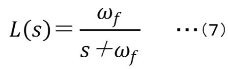
また、式(3)を標準化すると式(4)となる。

ここで、固有角振動数をωv(rad/s)、減衰比をζとする。式(4)におけるパラメータmv、ωv、ζを設定することにより、掘削対象の様々な感覚の創出を可能とする。本実施形態では、振動させず高い応答性を得る目的でζ=1とする。掘削力を印加したときに硬いと感じる感覚の創出では、パラメータのmv、ωvを大きく与え、抵抗の大きい弾性体を作り出すことで、掘削力F(N)が入力された際に、変位を生じさせず硬いと感じさせることができる。その値は、表1上段に示すとおりであり、パラメータを徐々に増加させていき、十分硬いと感じ、それ以上大きくしても変化が見込まれないと判断した値である。
制御部82は、掘削対象が削れた際にノミが抜ける様な感覚を創出するために、以下のように制御する。まず、制御部82は、掘削力F(N)を蓄積し、式(5)のように、掘削対象の現在の状態r(k)を一つ前の状態r(k-1)と力積を加算していく。次に、加算した力積の値が設定値を超えた際に、表1上段に示したパラメータから、表1下段に示すような、人間が手を自然に動かした状態に近いと感じたときの各パラメータに瞬間的に切り替えるようにする。これにより、掘削感付与装置100は、掘削対象が削れた際にノミが抜ける様な感覚を創出することができる。なお、表1下段に示したパラメータは、切り替えた後に台車に過剰な挙動がないよう、バネ定数kvは0としていない。
Here, the natural angular frequency is ω v (rad/s), and the damping ratio is ζ. By setting the parameters m v , ω v , and ζ in Equation (4), it is possible to create various sensations of the excavation target. In this embodiment, .zeta.=1 for the purpose of obtaining high responsiveness without causing vibration. To create a feeling of hardness when an excavation force is applied, the parameters mv and ωv are given large values to create an elastic body with a large resistance. It can be made to feel hard without causing The values are as shown in the upper part of Table 1, and are the values determined by gradually increasing the parameter, feeling that the material is sufficiently hard, and not expecting any change even if the parameter is increased further.
The
![]()
![]()

ここで、離散時間をk、サンプリング時間をΔt、参照係数をαとする。r(k)に所定の設定値を設け、設定値を超えた際にパラメータが切り替わる。
フィードフォワード制御器では、駆動機構60を仮想モデルの仮想状態に応じて制御するように、次式のようにする。
Here, k is the discrete time, Δt is the sampling time, and α is the reference coefficient. A predetermined set value is provided for r(k), and the parameter is switched when the set value is exceeded.
In the feedforward controller, the following equation is used so as to control the

そして、フィードバック制御器は、駆動機構60からの出力と仮想モデルからの出力の偏差を補償するために設置される。本実施形態ではフィードバック制御器をPD制御とする。PD制御器を次式に示す。
A feedback controller is then installed to compensate for deviations in the output from the
![]()
![]()
図9は、金槌で操作端1に掘削力を加えたときの実験結果を示す。掘削力Fを断続的に印加すると、パラメータ変化前では変位は非常に小さく、硬い感覚を創出していることが確認される。r(k)の値は徐々に増加し、設定値を超えた際に台車が瞬間的に移動することで、物体が削れた際のノミが抜けるような感覚が創出される。このパラメータ変化は、r(k)の設定値に依存しているため、この設定値を操作しパラメータ変化時期を調節することで、切削材料の板厚の想定も可能とする。また、ノミの抜ける際に発生する加速度は4.55m/s2と、操作者に違和感を与えない高い加速度が生成されていることが確認される。即ち、これにより、掘削感付与装置は、掘削対象の質量が大きい場合にも、高い応答性を発揮できることが確認される。
FIG. 9 shows experimental results when a digging force is applied to the operating
図10は、図9においてフィードフォワード制御を行わず、フィードバック制御だけにより金槌で操作端1に掘削力を加えたときの実験結果を示す。その結果、ノミの抜ける際に発生する加速度は1.5m/s2であり、図9の加速度4.55m/s2に比べて小さい加速度となった。この結果から、掘削感付与装置100がフィードフォワード制御器を備えていないと、備えている場合と比べて駆動機構60の初期の駆動速度が遅くなるため、印加された掘削力に対し高い応答性が得えられないことが確認された。換言すると、掘削感付与装置100ではフィードフォワード制御を行わないと、臨場感のあるノミが抜けるような感覚を操作者が十分に得られないことが確認された。
FIG. 10 shows experimental results when the excavating force was applied to the operating
<第2の実施形態>
ここで、第2の実施形態の技能評価装置について、図面を参照して詳細に説明する。
本発明の第2の実施形態の技能評価装置は、ジョイント構造物として本発明のジョイント構造物を用いており、本発明のジョイント構造物は本発明の技能評価装置に含まれる。
<Second embodiment>
Here, the skill evaluation device of the second embodiment will be described in detail with reference to the drawings.
The skill evaluation device of the second embodiment of the present invention uses the joint structure of the present invention as a joint structure, and the joint structure of the present invention is included in the skill evaluation device of the present invention.
図11は、本発明の第2の実施形態の技能評価装置300の一例を示す概略斜視図である。この図11の技能評価装置300は、評価手段310を有する以外は、図1の掘削感付与装置100と同じ構成を有するので、同一構成部分には同一符号を付し、重複した説明を省略する場合がある。また、下記構成部材の数、位置、形状等は本実施形態に限定されず、本発明を実施する上で好ましい数、位置、形状等にすることができる。
FIG. 11 is a schematic perspective view showing an example of a
評価手段310は、想定操作者における掘削力の大きさ及び印加方向の少なくともいずれかを予め記憶している基準データと比較して操作者の技能を評価する手段である。
本実施形態では、想定操作者として熟練者の掘削力の大きさ及び印加方向の少なくともいずれかを予め記憶しておき基準データとし、この基準データに基づき、操作者の技能を評価する。
評価方法としては、例えば、基準データの操作者のデータとの差の平均値、標準偏差を求める方法、時系列の基準データとの相関を求める方法、時系列の基準データから外れたエラーの数の累積値を求める方法、などが挙げられる。
The evaluation means 310 is means for evaluating the operator's skill by comparing at least one of the excavation force magnitude and application direction of the assumed operator with pre-stored reference data.
In the present embodiment, at least one of the magnitude and application direction of the excavation force of an expert as an assumed operator is stored in advance and used as reference data, and the skill of the operator is evaluated based on this reference data.
Evaluation methods include, for example, the average value and standard deviation of the difference between the reference data and the operator's data, the method of obtaining the correlation with the time-series reference data, and the number of errors that deviate from the time-series reference data. , and the like.
なお、本発明の第1の実施形態及び第2の実施形態では、操作者が被掘削操作部として操作端1に金槌で掘削力を加えたが、これに限ることなく、操作者が被掘削操作部としての被回動乃至回転部に回動乃至回転時における押圧力を印加することにより、操作者に対しドリルなどによる掘削操作の人工現実感を与えることも可能である。
In the first and second embodiments of the present invention, the operator applied the excavating force with a hammer to the
本発明の態様は、例えば、以下のとおりである。
<1> 想定された掘削対象に対する模擬の掘削操作が操作者により行われる被掘削操作部を有する掘削操作手段と、
前記被掘削操作部に印加された掘削力に応じて、前記掘削操作手段を介して前記操作者に対して人工的な掘削感を付与する掘削感付与手段と、
を有することを特徴とする掘削感付与装置である。
<2> 前記被掘削操作部が、打撃手段により打撃されることにより、前記掘削力が印加される被打撃部である前記<1>に記載の掘削感付与装置である。
<3> 前記被掘削操作部が、押圧されながら回動乃至回転されることにより、押圧力、及び回動力乃至回転力が前記掘削力として印加される被回動乃至回転部である前記<1>に記載の掘削感付与装置である。
<4> 前記掘削感付与手段が、
前記被掘削操作部と接続されたボールリテーナと、
前記ボールリテーナを押圧しつつ前記ボールリテーナの回動を案内する回動案内部材と、
棒状部材であって、前記ボールリテーナに接続される接続部と、前記回動案内部材により案内された前記ボールリテーナの回動方向と直交する方向に前記棒状部材を回動可能に軸支する軸支部とを有する棒状部材と、
を有する前記<1>から<3>のいずれかに記載の掘削感付与装置である。
<5> 前記回動案内部材が、
前記ボールリテーナを押圧する面を有する一対の部材と、
前記一対の部材が前記ボールリテーナを押圧するように前記一対の部材を付勢する付勢部材と、
を有する前記<4>に記載の掘削感付与装置である。
<6> 前記掘削感付与手段が、前記被掘削操作部に印加された掘削力の大きさと印加方向とを検出する検出部を有する前記<1>から<5>のいずれかに記載の掘削感付与装置である。
<7> 前記検出部が、6軸力覚センサである前記<6>に記載の掘削感付与装置である。
<8> 前記検出部が検出した掘削力の大きさと印加方向とに応じて、
前記掘削力が印加される前の前記被掘削操作部の位置から、
前記掘削力が印加されたときに所定位置に所定速度で前記被掘削操作部が移動するように制御する制御部を有する前記<6>から<7>のいずれかに記載の掘削感付与装置である。
<9> 前記制御部による制御が、フィードバック制御とフィードフォワード制御との組合せにより行われる前記<8>に記載の掘削感付与装置である。
<10> 前記制御部が、
前記被掘削操作部に単回乃至複数回印加された前記掘削力の大きさの累積が設定値を超えると、
前記設定値を超えるまでの間における前記被掘削操作部を移動させる所定速度よりも速い速度で前記被掘削操作部を移動させる、前記<8>から<9>のいずれかに記載の掘削感付与装置である。
<11> 仮想空間表示手段を更に有し、
前記仮想空間表示手段が、少なくとも前記想定された掘削対象を仮想空間上に表示する前記<1>から<10>のいずれかに記載の掘削感付与装置である。
<12> 前記掘削感付与装置の設置面内における、X方向、及び前記X方向と直交するY方向、並びに、前記設置面と直交するZ方向の各方向に前記掘削操作手段を移動可能に支持する支持手段を更に有する前記<1>から<11>のいずれかに記載の掘削感付与装置である。
<13> 前記支持手段が、リニアガイドである前記<12>に記載の掘削感付与装置である。
<14> ボールリテーナと、
前記ボールリテーナを押圧しつつ前記ボールリテーナの回動を案内する回動案内部材と、
棒状部材であって、前記ボールリテーナに接続される接続部と、前記回動案内部材により案内された前記ボールリテーナの回動方向と直交する方向に前記棒状部材を回動可能に軸支する軸支部とを有する棒状部材と、
を有することを特徴とするジョイント構造物である。
<15> 前記回動案内部材が、
前記ボールリテーナを押圧する面を有する一対の部材と、
前記一対の部材が前記ボールリテーナを押圧するように前記一対の部材を付勢する付勢部材と、
を有する前記<14>に記載のジョイント構造物である。
<16> 想定された掘削対象に対する模擬の掘削操作が被掘削操作部に対して操作者により行われる掘削操作工程と、
前記掘削操作工程で前記被掘削操作部に印加された掘削力に応じて、前記掘削操作工程を介して前記操作者に対して人工的な掘削感を付与する掘削感付与工程と、
を含むことを特徴とする掘削感付与方法である。
<17> 想定された掘削対象に対する模擬の掘削操作が操作者により行われる被掘削操作部を有する掘削操作手段と、
前記被掘削操作部に印加された掘削力に応じて、前記掘削操作手段を介して前記操作者に対して人工的な掘削感を付与する掘削感付与手段と、
想定操作者における掘削力の大きさ及び印加方向の少なくともいずれかを予め記憶している基準データと比較して前記操作者の技能を評価する評価手段と、
を有することを特徴とする技能評価装置である。
<18> 想定された掘削対象に対する模擬の掘削操作が被掘削操作部に対して操作者により行われる掘削操作工程と、
前記被掘削操作部に印加された掘削力に応じて、前記掘削操作手段を介して前記操作者に対して人工的な掘削感を付与する掘削感付与工程と、
想定操作者における掘削力の大きさ及び印加方向の少なくともいずれかを予め記憶している基準データと比較して前記操作者の技能を評価する評価工程と、
を含むことを特徴とする技能評価方法である。
<19> 操作者により行われる想定された掘削対象に対する模擬の掘削操作を、被掘削操作部を有する掘削操作手段を介して受け付け、
前記被掘削操作部に印加された掘削力に応じて、前記掘削操作手段を介して前記操作者に対して人工的な掘削感を付与する、
処理をコンピュータに実行させることを特徴とする掘削感付与プログラムである。
<20> 操作者により行われる想定された掘削対象に対する模擬の掘削操作を、被掘削操作部を有する掘削操作手段を介して受け付け、
前記被掘削操作部に印加された掘削力に応じて、前記掘削操作手段を介して前記操作者に対して人工的な掘削感を付与し、
想定操作者における掘削力の大きさ及び印加方向の少なくともいずれかを予め記憶している基準データと比較して前記操作者の技能を評価する
処理をコンピュータに実行させることを特徴とする技能評価プログラムである。
Aspects of the present invention are, for example, as follows.
<1> an excavation operation means having an excavation operation section in which an operator performs a simulated excavation operation on an assumed excavation target;
excavation feeling imparting means for imparting an artificial excavation feeling to the operator via the excavation operation means according to the excavation force applied to the excavated operation part;
It is an excavation feeling imparting device characterized by having
<2> The excavation sensation imparting device according to <1>, wherein the excavation operation portion is a hit portion to which the excavation force is applied by being hit by a hitting means.
<3> The excavating operation portion is a rotated or rotated portion to which a pressing force and a rotating force or a rotating force are applied as the excavating force by being rotated or rotated while being pressed. > is the device for imparting a feeling of excavation according to the above.
<4> The excavation feeling imparting means includes:
a ball retainer connected to the excavated operation part;
a rotation guide member that guides the rotation of the ball retainer while pressing the ball retainer;
A rod-shaped member, a connecting portion connected to the ball retainer, and a shaft that supports the rod-shaped member so as to be rotatable in a direction perpendicular to the rotation direction of the ball retainer guided by the rotation guide member. a rod-shaped member having a branch;
The device for imparting a feeling of excavation according to any one of <1> to <3>.
<5> The rotation guide member is
a pair of members having surfaces for pressing the ball retainer;
a biasing member that biases the pair of members so that the pair of members presses the ball retainer;
The device for imparting a feeling of excavation according to <4>.
<6> The excavation feeling according to any one of <1> to <5>, wherein the excavation feeling imparting means has a detection unit for detecting the magnitude and application direction of the excavation force applied to the excavated operation part. Applicator.
<7> The excavation feeling imparting device according to <6>, wherein the detection unit is a 6-axis force sensor.
<8> Depending on the magnitude and application direction of the excavation force detected by the detection unit,
from the position of the excavated operation part before the excavation force is applied,
The excavation feeling imparting device according to any one of <6> to <7>, further comprising a control unit that controls the excavation operation unit to move to a predetermined position at a predetermined speed when the excavation force is applied. be.
<9> The excavation feeling imparting device according to <8>, wherein the control by the control unit is performed by a combination of feedback control and feedforward control.
<10> The control unit
When the cumulative magnitude of the excavating force applied to the excavating operation portion once or multiple times exceeds a set value,
The feeling of excavation according to any one of <8> to <9>, wherein the operation part to be excavated is moved at a speed higher than a predetermined speed for moving the operation part to be excavated until the set value is exceeded. It is a device.
<11> further comprising virtual space display means;
The excavation feeling imparting device according to any one of <1> to <10>, wherein the virtual space display means displays at least the assumed excavation object in a virtual space.
<12> The excavation operation means is movably supported in each of the X direction, the Y direction orthogonal to the X direction, and the Z direction orthogonal to the installation surface within the installation surface of the excavation feeling imparting device. The device for imparting a feeling of excavation according to any one of <1> to <11>, further comprising support means for providing a feeling of excavation.
<13> The device for imparting a feeling of excavation according to <12>, wherein the support means is a linear guide.
<14> a ball retainer;
a rotation guide member that guides the rotation of the ball retainer while pressing the ball retainer;
A rod-shaped member, a connecting portion connected to the ball retainer, and a shaft that supports the rod-shaped member so as to be rotatable in a direction perpendicular to the rotation direction of the ball retainer guided by the rotation guide member. a rod-shaped member having a branch;
A joint structure characterized by having
<15> The rotation guide member is
a pair of members having surfaces for pressing the ball retainer;
a biasing member that biases the pair of members so that the pair of members presses the ball retainer;
The joint structure according to <14>.
<16> an excavation operation step in which an operator performs a simulated excavation operation on an assumed excavation target on the excavated operation unit;
an excavation feeling imparting step of imparting an artificial excavation feeling to the operator through the excavation operation step according to the excavation force applied to the excavated operation part in the excavation operation step;
A method for imparting an excavation feeling, characterized by comprising:
<17> an excavation operation means having an excavation operation section in which an operator performs a simulated excavation operation on an assumed excavation target;
excavation feeling imparting means for imparting an artificial excavation feeling to the operator via the excavation operation means according to the excavation force applied to the excavated operation part;
evaluation means for evaluating the operator's skill by comparing at least one of the magnitude and application direction of the excavation force of an assumed operator with reference data stored in advance;
It is a skill evaluation device characterized by having
<18> an excavation operation step in which an operator performs a simulated excavation operation on an assumed excavation target on the excavated operation unit;
an excavation feeling imparting step of imparting an artificial excavation feeling to the operator via the excavation operation means according to the excavation force applied to the excavated operation part;
an evaluation step of comparing at least one of the magnitude and application direction of the excavation force of an assumed operator with reference data stored in advance to evaluate the skill of the operator;
A skill evaluation method characterized by including
<19> Receiving a simulated excavation operation for an assumed excavation target performed by an operator via an excavation operation means having an excavation operation unit;
Giving an artificial excavation feeling to the operator via the excavation operation means according to the excavation force applied to the excavated operation part;
It is an excavation feeling imparting program characterized by causing a computer to execute processing.
<20> Receiving a simulated excavation operation for an assumed excavation target performed by an operator via an excavation operation means having an excavation operation unit;
giving an artificial excavation feeling to the operator via the excavation operation means according to the excavation force applied to the excavated operation part;
A skill evaluation program characterized by causing a computer to execute a process of evaluating the skill of an assumed operator by comparing at least one of the magnitude and direction of application of the excavation force of the assumed operator with pre-stored reference data. is.
前述の<1>から<13>のいずれかに記載の掘削感付与装置、前述の<14>から<15>のいずれかに記載のジョイント構造物、前述の<16>に記載の掘削感付与方法、前述の<17>に記載の技能評価装置、前述の<18>に記載の技能評価方法、前述の<19>に記載の掘削感付与プログラム、及び前述の<20>に記載の技能評価プログラムによると、従来における前述の諸問題を解決し、前述の本発明の目的を達成することができる。 The excavation feeling imparting device according to any one of <1> to <13> above, the joint structure according to any one of <14> to <15> above, and the excavation feeling imparting device according to <16> above. The method, the skill evaluation device according to <17> above, the skill evaluation method according to <18> above, the drilling feeling imparting program according to <19> above, and the skill evaluation according to <20> above. According to the program, it is possible to solve the above-mentioned conventional problems and achieve the above-mentioned object of the present invention.
1 操作端
1a 被打撃部(打撃面)
2 X軸リニアガイド
3 Y軸リニアガイド
4 Z軸リニアガイド
6 6軸力覚センサ
7 X軸サーボモータ
8 Y軸サーボモータ
9 Z軸サーボモータ
10 X軸補助ガイド
11 制御部
12 基台
14 ボールリテーナ
15 X軸回転方向サーボモータ
16 Y軸回転方向サーボモータ
17 Z軸回転方向サーボモータ
22 基盤
33 支持アーム
50 ジョイント構造部
60 駆動機構
70 コンピュータ
90 ヘッドマウントディスプレイ
100 掘削感付与装置
300 技能評価装置
310 評価手段
1 operating
2 X-axis linear guide 3 Y-axis linear guide 4 Z-axis
Claims (15)
前記被掘削操作部に印加された掘削力に応じて、前記掘削操作手段を介して前記掘削対象の材質を掘削する動作に近い力覚を提示することにより前記操作者に対して人工的な掘削感を付与する掘削感付与手段と、
を有し、
前記被掘削操作部が、打撃手段により打撃されることにより、前記掘削力が印加される被打撃部である;又は押圧されながら回動乃至回転されることにより、押圧力、及び回動力乃至回転力が前記掘削力として印加される被回動乃至回転部であることを特徴とする掘削感付与装置。 an excavation operation means having an excavation operation section for an operator to perform a simulated excavation operation on an assumed excavation target;
artificial excavation to the operator by presenting a force sensation close to an excavation action of the material of the excavation object via the excavation operation means according to the excavation force applied to the excavation operation part; an excavation feeling imparting means for imparting a feeling;
has
The excavating operation part is a hit part to which the excavation force is applied by being hit by the hitting means; An excavation feeling imparting device characterized by being a rotated or rotating part to which a force is applied as the excavation force.
前記被掘削操作部と接続されたボールリテーナと、
前記ボールリテーナを押圧しつつ前記ボールリテーナの回動を案内する回動案内部材と、
棒状部材であって、前記ボールリテーナに接続される接続部と、前記回動案内部材により案内された前記ボールリテーナの回動方向と直交する方向に前記棒状部材を回動可能に軸支する軸支部とを有する棒状部材と、
を有する請求項1に記載の掘削感付与装置。 The excavation feeling imparting means is
a ball retainer connected to the excavated operation part;
a rotation guide member that guides the rotation of the ball retainer while pressing the ball retainer;
A rod-shaped member, a connecting portion connected to the ball retainer, and a shaft that supports the rod-shaped member so as to be rotatable in a direction perpendicular to the rotation direction of the ball retainer guided by the rotation guide member. a rod-shaped member having a branch;
The excavation feeling imparting device according to claim 1, comprising:
前記ボールリテーナを押圧する面を有する一対の部材と、
前記一対の部材が前記ボールリテーナを押圧するように前記一対の部材を付勢する付勢部材と、
を有する請求項2に記載の掘削感付与装置。 The rotation guide member is
a pair of members having surfaces for pressing the ball retainer;
a biasing member that biases the pair of members so that the pair of members presses the ball retainer;
The excavation feeling imparting device according to claim 2, comprising:
前記掘削力が印加される前の前記被掘削操作部の位置から、
前記掘削力が印加されたときに所定位置に所定速度で前記被掘削操作部が移動するように制御する制御部を有する請求項4から5のいずれかに記載の掘削感付与装置。 Depending on the magnitude and application direction of the excavation force detected by the detection unit,
from the position of the excavated operation part before the excavation force is applied,
6. The excavation feeling imparting device according to claim 4, further comprising a control section for controlling the excavation operation section to move to a predetermined position at a predetermined speed when the excavation force is applied.
前記被掘削操作部に単回乃至複数回印加された前記掘削力の大きさの累積が設定値を超えると、
前記設定値を超えるまでの間における前記被掘削操作部を移動させる所定速度よりも速い速度で前記被掘削操作部を移動させる、請求項6から7のいずれかに記載の掘削感付与装置。 The control unit
When the cumulative magnitude of the excavating force applied to the excavating operation portion once or multiple times exceeds a set value,
8. The excavation feeling imparting device according to claim 6, wherein the excavated operation part is moved at a speed higher than a predetermined speed for moving the excavated operation part until the set value is exceeded.
前記仮想空間表示手段が、少なくとも前記想定された掘削対象を仮想空間上に表示する請求項1から8のいずれかに記載の掘削感付与装置。 further comprising virtual space display means;
9. The excavation feeling imparting device according to any one of claims 1 to 8, wherein the virtual space display means displays at least the assumed excavation object in the virtual space.
前記掘削操作工程で前記被掘削操作部に印加された掘削力に応じて、前記被掘削操作部を有する掘削操作手段を介して前記掘削対象の材質を掘削する動作に近い力覚を提示することにより人工的な掘削感が付与される掘削感付与工程と、
を含み、
前記被掘削操作部が、打撃手段により打撃されることにより、前記掘削力が印加される被打撃部である;又は押圧されながら回動乃至回転されることにより、押圧力、及び回動力乃至回転力が前記掘削力として印加される被回動乃至回転部であることを特徴とする掘削感付与方法。 an excavation operation step in which a simulated excavation operation for an assumed excavation target is performed on the excavated operation part;
In the excavation operation step, according to the excavation force applied to the operation subject to be excavated, a force sense similar to that of excavating the material of the object to be excavated is presented via excavation operation means having the operation subject to excavation. an excavation feeling imparting step in which an artificial excavation feeling is imparted by
including
The excavating operation part is a hit part to which the excavation force is applied by being hit by the hitting means; A method for imparting an excavation feeling, wherein a force is a rotated or rotating part to which a force is applied as the excavation force.
前記被掘削操作部に印加された掘削力に応じて、前記掘削操作手段を介して前記掘削対象の材質を掘削する動作に近い力覚を提示することにより前記操作者に対して人工的な掘削感を付与する、
処理をコンピュータに実行させ、
前記被掘削操作部が、打撃手段により打撃されることにより、前記掘削力が印加される被打撃部である;又は押圧されながら回動乃至回転されることにより、押圧力、及び回動力乃至回転力が前記掘削力として印加される被回動乃至回転部である ことを特徴とする掘削感付与プログラム。 receiving a simulated excavation operation for an assumed excavation target performed by an operator via an excavation operation means having an excavation operation part;
According to the excavation force applied to the excavated operation part, the excavation target materialoperation to drillgiving an artificial excavation feeling to the operator by presenting a force sense close to
let the computer do the work,
The excavation operation part is a hit part to which the excavation force is applied by being hit by the hitting means; is a rotated or rotating part to which a force is applied as said digging force An excavation feeling imparting program characterized by:
前記被掘削操作部に印加された掘削力に応じて、前記掘削操作手段を介して前記掘削対象の材質を掘削する動作に近い力覚を提示することにより前記操作者に対して人工的な掘削感を付与し、 artificial excavation to the operator by presenting a force sensation close to an excavation action of the material of the excavation object via the excavation operation means according to the excavation force applied to the excavation operation part; give a sense of
想定操作者における掘削力の大きさ及び印加方向の少なくともいずれかを予め記憶している基準データと比較して前記操作者の技能を評価する、 Evaluating the operator's skill by comparing at least one of the magnitude and application direction of the excavation force of the assumed operator with pre-stored reference data;
処理をコンピュータに実行させることを特徴とする技能評価プログラム。 A skill evaluation program characterized by causing a computer to execute processing.
Priority Applications (2)
| Application Number | Priority Date | Filing Date | Title |
|---|---|---|---|
| JP2018024902A JP7148774B2 (en) | 2018-02-15 | 2018-02-15 | Drilling sensation imparting device, joint structure, drilling sensation imparting method, drilling sensation imparting program, skill evaluation device, skill evaluation method, and skill evaluation program |
| JP2021172763A JP2022009382A (en) | 2018-02-15 | 2021-10-22 | Joint structure |
Applications Claiming Priority (1)
| Application Number | Priority Date | Filing Date | Title |
|---|---|---|---|
| JP2018024902A JP7148774B2 (en) | 2018-02-15 | 2018-02-15 | Drilling sensation imparting device, joint structure, drilling sensation imparting method, drilling sensation imparting program, skill evaluation device, skill evaluation method, and skill evaluation program |
Related Child Applications (1)
| Application Number | Title | Priority Date | Filing Date |
|---|---|---|---|
| JP2021172763A Division JP2022009382A (en) | 2018-02-15 | 2021-10-22 | Joint structure |
Publications (2)
| Publication Number | Publication Date |
|---|---|
| JP2019136437A JP2019136437A (en) | 2019-08-22 |
| JP7148774B2 true JP7148774B2 (en) | 2022-10-06 |
Family
ID=67692617
Family Applications (2)
| Application Number | Title | Priority Date | Filing Date |
|---|---|---|---|
| JP2018024902A Active JP7148774B2 (en) | 2018-02-15 | 2018-02-15 | Drilling sensation imparting device, joint structure, drilling sensation imparting method, drilling sensation imparting program, skill evaluation device, skill evaluation method, and skill evaluation program |
| JP2021172763A Pending JP2022009382A (en) | 2018-02-15 | 2021-10-22 | Joint structure |
Family Applications After (1)
| Application Number | Title | Priority Date | Filing Date |
|---|---|---|---|
| JP2021172763A Pending JP2022009382A (en) | 2018-02-15 | 2021-10-22 | Joint structure |
Country Status (1)
| Country | Link |
|---|---|
| JP (2) | JP7148774B2 (en) |
Families Citing this family (1)
| Publication number | Priority date | Publication date | Assignee | Title |
|---|---|---|---|---|
| JP7424926B2 (en) * | 2020-06-26 | 2024-01-30 | 株式会社日立製作所 | digitization system |
Citations (3)
| Publication number | Priority date | Publication date | Assignee | Title |
|---|---|---|---|---|
| JP2003532144A (en) | 2000-04-26 | 2003-10-28 | ユニベルシテ パリ 7 − ドニ ディドロ | Training apparatus and method with virtual reality for dentistry |
| US20100311028A1 (en) | 2009-06-04 | 2010-12-09 | Zimmer Dental, Inc. | Dental Implant Surgical Training Simulation System |
| JP2013030053A (en) | 2011-07-29 | 2013-02-07 | Tohoku Univ | Force sense presentation device |
Family Cites Families (5)
| Publication number | Priority date | Publication date | Assignee | Title |
|---|---|---|---|---|
| JPS5276853U (en) * | 1976-11-19 | 1977-06-08 | ||
| JPH064128Y2 (en) * | 1989-12-07 | 1994-02-02 | 株式会社丸山製作所 | Operating device for continuously variable transmission |
| JPH0612137A (en) * | 1992-05-25 | 1994-01-21 | Sakae Tsushin Kogyo Kk | Operation shaft guide structure |
| JP3273377B2 (en) * | 1992-11-04 | 2002-04-08 | スズキ株式会社 | Shift lever device |
| JP3167958B2 (en) * | 1997-05-08 | 2001-05-21 | コナミ株式会社 | Multi-directional switching operation device |
-
2018
- 2018-02-15 JP JP2018024902A patent/JP7148774B2/en active Active
-
2021
- 2021-10-22 JP JP2021172763A patent/JP2022009382A/en active Pending
Patent Citations (3)
| Publication number | Priority date | Publication date | Assignee | Title |
|---|---|---|---|---|
| JP2003532144A (en) | 2000-04-26 | 2003-10-28 | ユニベルシテ パリ 7 − ドニ ディドロ | Training apparatus and method with virtual reality for dentistry |
| US20100311028A1 (en) | 2009-06-04 | 2010-12-09 | Zimmer Dental, Inc. | Dental Implant Surgical Training Simulation System |
| JP2013030053A (en) | 2011-07-29 | 2013-02-07 | Tohoku Univ | Force sense presentation device |
Also Published As
| Publication number | Publication date |
|---|---|
| JP2019136437A (en) | 2019-08-22 |
| JP2022009382A (en) | 2022-01-14 |
Similar Documents
| Publication | Publication Date | Title |
|---|---|---|
| JP6049788B2 (en) | Virtual tool operation system | |
| JP6956081B2 (en) | Robot system and how to backdrive the robot system | |
| JP4705928B2 (en) | Force-sensitive tactile interface | |
| Salcudean et al. | A robot system for medical ultrasound | |
| US9037295B2 (en) | Dynamic physical constraint for hard surface emulation | |
| Prattichizzo et al. | Cutaneous force feedback as a sensory subtraction technique in haptics | |
| Schorr et al. | Tactor-induced skin stretch as a sensory substitution method in teleoperated palpation | |
| Kasahara et al. | Telerobotic‐assisted bone‐drilling system using bilateral control with feed operation scaling and cutting force scaling | |
| US20060106369A1 (en) | Haptic interface for force reflection in manipulation tasks | |
| O’malley et al. | Haptic interfaces | |
| Walker et al. | Holdable haptic device for 4-dof motion guidance | |
| L’Orsa et al. | Introduction to haptics for neurosurgeons | |
| Lee et al. | A master manipulator with a remote‐center‐of‐motion kinematic structure for a minimally invasive robotic surgical system | |
| Wang et al. | A robotic system with force feedback for micro-surgery | |
| CN119212643B (en) | Adaptive damper for computer-aided systems | |
| JP7148774B2 (en) | Drilling sensation imparting device, joint structure, drilling sensation imparting method, drilling sensation imparting program, skill evaluation device, skill evaluation method, and skill evaluation program | |
| Maier et al. | Force-feedback assisted and virtual fixtures based K-wire drilling simulation | |
| US20240375282A1 (en) | Techniques for following commands of an input device using a constrained proxy | |
| Yu et al. | Frequency-based analysis of the relationship between cutting force and CT number for an implant-surgery-teaching robot | |
| Wu et al. | Effects of velocity on human force control | |
| Pratticò et al. | A breakdown study of a mockup-based consumer haptic setup for virtual reality | |
| Fehlberg et al. | Improved active handrest performance through use of virtual fixtures | |
| Fjellin | Design of a bilateral master-slave system with haptic feedback for ultrasound examinations | |
| Verner et al. | 15 effects of gripping and translational forces on teleoperation | |
| Provancher et al. | Tactile perception of rotational sliding |
Legal Events
| Date | Code | Title | Description |
|---|---|---|---|
| A80 | Written request to apply exceptions to lack of novelty of invention |
Free format text: JAPANESE INTERMEDIATE CODE: A80 Effective date: 20180316 |
|
| RD04 | Notification of resignation of power of attorney |
Free format text: JAPANESE INTERMEDIATE CODE: A7424 Effective date: 20190220 |
|
| A621 | Written request for application examination |
Free format text: JAPANESE INTERMEDIATE CODE: A621 Effective date: 20201027 |
|
| A131 | Notification of reasons for refusal |
Free format text: JAPANESE INTERMEDIATE CODE: A131 Effective date: 20210824 |
|
| A977 | Report on retrieval |
Free format text: JAPANESE INTERMEDIATE CODE: A971007 Effective date: 20210827 |
|
| A521 | Request for written amendment filed |
Free format text: JAPANESE INTERMEDIATE CODE: A523 Effective date: 20211014 |
|
| A131 | Notification of reasons for refusal |
Free format text: JAPANESE INTERMEDIATE CODE: A131 Effective date: 20220315 |
|
| A521 | Request for written amendment filed |
Free format text: JAPANESE INTERMEDIATE CODE: A523 Effective date: 20220404 |
|
| RD03 | Notification of appointment of power of attorney |
Free format text: JAPANESE INTERMEDIATE CODE: A7423 Effective date: 20220519 |
|
| TRDD | Decision of grant or rejection written | ||
| A01 | Written decision to grant a patent or to grant a registration (utility model) |
Free format text: JAPANESE INTERMEDIATE CODE: A01 Effective date: 20220809 |
|
| A61 | First payment of annual fees (during grant procedure) |
Free format text: JAPANESE INTERMEDIATE CODE: A61 Effective date: 20220902 |
|
| R150 | Certificate of patent or registration of utility model |
Ref document number: 7148774 Country of ref document: JP Free format text: JAPANESE INTERMEDIATE CODE: R150 |
|
| R250 | Receipt of annual fees |
Free format text: JAPANESE INTERMEDIATE CODE: R250 |