JP7136612B2 - Conveyor with local purge function - Google Patents
Conveyor with local purge function Download PDFInfo
- Publication number
- JP7136612B2 JP7136612B2 JP2018133067A JP2018133067A JP7136612B2 JP 7136612 B2 JP7136612 B2 JP 7136612B2 JP 2018133067 A JP2018133067 A JP 2018133067A JP 2018133067 A JP2018133067 A JP 2018133067A JP 7136612 B2 JP7136612 B2 JP 7136612B2
- Authority
- JP
- Japan
- Prior art keywords
- atmosphere
- inert gas
- semiconductor wafer
- wafer
- replacement function
- Prior art date
- Legal status (The legal status is an assumption and is not a legal conclusion. Google has not performed a legal analysis and makes no representation as to the accuracy of the status listed.)
- Active
Links
Images


Classifications
-
- H—ELECTRICITY
- H01—ELECTRIC ELEMENTS
- H01L—SEMICONDUCTOR DEVICES NOT COVERED BY CLASS H10
- H01L21/00—Processes or apparatus adapted for the manufacture or treatment of semiconductor or solid state devices or of parts thereof
- H01L21/67—Apparatus specially adapted for handling semiconductor or electric solid state devices during manufacture or treatment thereof; Apparatus specially adapted for handling wafers during manufacture or treatment of semiconductor or electric solid state devices or components ; Apparatus not specifically provided for elsewhere
- H01L21/677—Apparatus specially adapted for handling semiconductor or electric solid state devices during manufacture or treatment thereof; Apparatus specially adapted for handling wafers during manufacture or treatment of semiconductor or electric solid state devices or components ; Apparatus not specifically provided for elsewhere for conveying, e.g. between different workstations
- H01L21/67763—Apparatus specially adapted for handling semiconductor or electric solid state devices during manufacture or treatment thereof; Apparatus specially adapted for handling wafers during manufacture or treatment of semiconductor or electric solid state devices or components ; Apparatus not specifically provided for elsewhere for conveying, e.g. between different workstations the wafers being stored in a carrier, involving loading and unloading
- H01L21/67766—Mechanical parts of transfer devices
-
- B—PERFORMING OPERATIONS; TRANSPORTING
- B25—HAND TOOLS; PORTABLE POWER-DRIVEN TOOLS; MANIPULATORS
- B25J—MANIPULATORS; CHAMBERS PROVIDED WITH MANIPULATION DEVICES
- B25J11/00—Manipulators not otherwise provided for
- B25J11/0095—Manipulators transporting wafers
-
- B—PERFORMING OPERATIONS; TRANSPORTING
- B25—HAND TOOLS; PORTABLE POWER-DRIVEN TOOLS; MANIPULATORS
- B25J—MANIPULATORS; CHAMBERS PROVIDED WITH MANIPULATION DEVICES
- B25J15/00—Gripping heads and other end effectors
- B25J15/06—Gripping heads and other end effectors with vacuum or magnetic holding means
- B25J15/0616—Gripping heads and other end effectors with vacuum or magnetic holding means with vacuum
- B25J15/065—Gripping heads and other end effectors with vacuum or magnetic holding means with vacuum provided with separating means for releasing the gripped object after suction
- B25J15/0658—Pneumatic type, e.g. air blast or overpressure
-
- F—MECHANICAL ENGINEERING; LIGHTING; HEATING; WEAPONS; BLASTING
- F24—HEATING; RANGES; VENTILATING
- F24F—AIR-CONDITIONING; AIR-HUMIDIFICATION; VENTILATION; USE OF AIR CURRENTS FOR SCREENING
- F24F13/00—Details common to, or for air-conditioning, air-humidification, ventilation or use of air currents for screening
- F24F13/02—Ducting arrangements
- F24F13/06—Outlets for directing or distributing air into rooms or spaces, e.g. ceiling air diffuser
-
- H—ELECTRICITY
- H01—ELECTRIC ELEMENTS
- H01L—SEMICONDUCTOR DEVICES NOT COVERED BY CLASS H10
- H01L21/00—Processes or apparatus adapted for the manufacture or treatment of semiconductor or solid state devices or of parts thereof
- H01L21/67—Apparatus specially adapted for handling semiconductor or electric solid state devices during manufacture or treatment thereof; Apparatus specially adapted for handling wafers during manufacture or treatment of semiconductor or electric solid state devices or components ; Apparatus not specifically provided for elsewhere
- H01L21/67005—Apparatus not specifically provided for elsewhere
- H01L21/67011—Apparatus for manufacture or treatment
- H01L21/67017—Apparatus for fluid treatment
-
- H—ELECTRICITY
- H01—ELECTRIC ELEMENTS
- H01L—SEMICONDUCTOR DEVICES NOT COVERED BY CLASS H10
- H01L21/00—Processes or apparatus adapted for the manufacture or treatment of semiconductor or solid state devices or of parts thereof
- H01L21/67—Apparatus specially adapted for handling semiconductor or electric solid state devices during manufacture or treatment thereof; Apparatus specially adapted for handling wafers during manufacture or treatment of semiconductor or electric solid state devices or components ; Apparatus not specifically provided for elsewhere
- H01L21/67005—Apparatus not specifically provided for elsewhere
- H01L21/67011—Apparatus for manufacture or treatment
- H01L21/67155—Apparatus for manufacturing or treating in a plurality of work-stations
- H01L21/67201—Apparatus for manufacturing or treating in a plurality of work-stations characterized by the construction of the load-lock chamber
-
- H—ELECTRICITY
- H01—ELECTRIC ELEMENTS
- H01L—SEMICONDUCTOR DEVICES NOT COVERED BY CLASS H10
- H01L21/00—Processes or apparatus adapted for the manufacture or treatment of semiconductor or solid state devices or of parts thereof
- H01L21/67—Apparatus specially adapted for handling semiconductor or electric solid state devices during manufacture or treatment thereof; Apparatus specially adapted for handling wafers during manufacture or treatment of semiconductor or electric solid state devices or components ; Apparatus not specifically provided for elsewhere
- H01L21/673—Apparatus specially adapted for handling semiconductor or electric solid state devices during manufacture or treatment thereof; Apparatus specially adapted for handling wafers during manufacture or treatment of semiconductor or electric solid state devices or components ; Apparatus not specifically provided for elsewhere using specially adapted carriers or holders; Fixing the workpieces on such carriers or holders
- H01L21/6735—Closed carriers
- H01L21/67373—Closed carriers characterised by locking systems
-
- H—ELECTRICITY
- H01—ELECTRIC ELEMENTS
- H01L—SEMICONDUCTOR DEVICES NOT COVERED BY CLASS H10
- H01L21/00—Processes or apparatus adapted for the manufacture or treatment of semiconductor or solid state devices or of parts thereof
- H01L21/67—Apparatus specially adapted for handling semiconductor or electric solid state devices during manufacture or treatment thereof; Apparatus specially adapted for handling wafers during manufacture or treatment of semiconductor or electric solid state devices or components ; Apparatus not specifically provided for elsewhere
- H01L21/673—Apparatus specially adapted for handling semiconductor or electric solid state devices during manufacture or treatment thereof; Apparatus specially adapted for handling wafers during manufacture or treatment of semiconductor or electric solid state devices or components ; Apparatus not specifically provided for elsewhere using specially adapted carriers or holders; Fixing the workpieces on such carriers or holders
- H01L21/6735—Closed carriers
- H01L21/67376—Closed carriers characterised by sealing arrangements
-
- H—ELECTRICITY
- H01—ELECTRIC ELEMENTS
- H01L—SEMICONDUCTOR DEVICES NOT COVERED BY CLASS H10
- H01L21/00—Processes or apparatus adapted for the manufacture or treatment of semiconductor or solid state devices or of parts thereof
- H01L21/67—Apparatus specially adapted for handling semiconductor or electric solid state devices during manufacture or treatment thereof; Apparatus specially adapted for handling wafers during manufacture or treatment of semiconductor or electric solid state devices or components ; Apparatus not specifically provided for elsewhere
- H01L21/673—Apparatus specially adapted for handling semiconductor or electric solid state devices during manufacture or treatment thereof; Apparatus specially adapted for handling wafers during manufacture or treatment of semiconductor or electric solid state devices or components ; Apparatus not specifically provided for elsewhere using specially adapted carriers or holders; Fixing the workpieces on such carriers or holders
- H01L21/6735—Closed carriers
- H01L21/67386—Closed carriers characterised by the construction of the closed carrier
-
- H—ELECTRICITY
- H01—ELECTRIC ELEMENTS
- H01L—SEMICONDUCTOR DEVICES NOT COVERED BY CLASS H10
- H01L21/00—Processes or apparatus adapted for the manufacture or treatment of semiconductor or solid state devices or of parts thereof
- H01L21/67—Apparatus specially adapted for handling semiconductor or electric solid state devices during manufacture or treatment thereof; Apparatus specially adapted for handling wafers during manufacture or treatment of semiconductor or electric solid state devices or components ; Apparatus not specifically provided for elsewhere
- H01L21/673—Apparatus specially adapted for handling semiconductor or electric solid state devices during manufacture or treatment thereof; Apparatus specially adapted for handling wafers during manufacture or treatment of semiconductor or electric solid state devices or components ; Apparatus not specifically provided for elsewhere using specially adapted carriers or holders; Fixing the workpieces on such carriers or holders
- H01L21/6735—Closed carriers
- H01L21/67389—Closed carriers characterised by atmosphere control
- H01L21/67393—Closed carriers characterised by atmosphere control characterised by the presence of atmosphere modifying elements inside or attached to the closed carrierl
-
- H—ELECTRICITY
- H01—ELECTRIC ELEMENTS
- H01L—SEMICONDUCTOR DEVICES NOT COVERED BY CLASS H10
- H01L21/00—Processes or apparatus adapted for the manufacture or treatment of semiconductor or solid state devices or of parts thereof
- H01L21/67—Apparatus specially adapted for handling semiconductor or electric solid state devices during manufacture or treatment thereof; Apparatus specially adapted for handling wafers during manufacture or treatment of semiconductor or electric solid state devices or components ; Apparatus not specifically provided for elsewhere
- H01L21/677—Apparatus specially adapted for handling semiconductor or electric solid state devices during manufacture or treatment thereof; Apparatus specially adapted for handling wafers during manufacture or treatment of semiconductor or electric solid state devices or components ; Apparatus not specifically provided for elsewhere for conveying, e.g. between different workstations
- H01L21/67763—Apparatus specially adapted for handling semiconductor or electric solid state devices during manufacture or treatment thereof; Apparatus specially adapted for handling wafers during manufacture or treatment of semiconductor or electric solid state devices or components ; Apparatus not specifically provided for elsewhere for conveying, e.g. between different workstations the wafers being stored in a carrier, involving loading and unloading
- H01L21/67772—Apparatus specially adapted for handling semiconductor or electric solid state devices during manufacture or treatment thereof; Apparatus specially adapted for handling wafers during manufacture or treatment of semiconductor or electric solid state devices or components ; Apparatus not specifically provided for elsewhere for conveying, e.g. between different workstations the wafers being stored in a carrier, involving loading and unloading involving removal of lid, door, cover
-
- H—ELECTRICITY
- H01—ELECTRIC ELEMENTS
- H01L—SEMICONDUCTOR DEVICES NOT COVERED BY CLASS H10
- H01L21/00—Processes or apparatus adapted for the manufacture or treatment of semiconductor or solid state devices or of parts thereof
- H01L21/67—Apparatus specially adapted for handling semiconductor or electric solid state devices during manufacture or treatment thereof; Apparatus specially adapted for handling wafers during manufacture or treatment of semiconductor or electric solid state devices or components ; Apparatus not specifically provided for elsewhere
- H01L21/677—Apparatus specially adapted for handling semiconductor or electric solid state devices during manufacture or treatment thereof; Apparatus specially adapted for handling wafers during manufacture or treatment of semiconductor or electric solid state devices or components ; Apparatus not specifically provided for elsewhere for conveying, e.g. between different workstations
- H01L21/67763—Apparatus specially adapted for handling semiconductor or electric solid state devices during manufacture or treatment thereof; Apparatus specially adapted for handling wafers during manufacture or treatment of semiconductor or electric solid state devices or components ; Apparatus not specifically provided for elsewhere for conveying, e.g. between different workstations the wafers being stored in a carrier, involving loading and unloading
- H01L21/67775—Docking arrangements
-
- H—ELECTRICITY
- H01—ELECTRIC ELEMENTS
- H01L—SEMICONDUCTOR DEVICES NOT COVERED BY CLASS H10
- H01L21/00—Processes or apparatus adapted for the manufacture or treatment of semiconductor or solid state devices or of parts thereof
- H01L21/67—Apparatus specially adapted for handling semiconductor or electric solid state devices during manufacture or treatment thereof; Apparatus specially adapted for handling wafers during manufacture or treatment of semiconductor or electric solid state devices or components ; Apparatus not specifically provided for elsewhere
- H01L21/677—Apparatus specially adapted for handling semiconductor or electric solid state devices during manufacture or treatment thereof; Apparatus specially adapted for handling wafers during manufacture or treatment of semiconductor or electric solid state devices or components ; Apparatus not specifically provided for elsewhere for conveying, e.g. between different workstations
- H01L21/67763—Apparatus specially adapted for handling semiconductor or electric solid state devices during manufacture or treatment thereof; Apparatus specially adapted for handling wafers during manufacture or treatment of semiconductor or electric solid state devices or components ; Apparatus not specifically provided for elsewhere for conveying, e.g. between different workstations the wafers being stored in a carrier, involving loading and unloading
- H01L21/67778—Apparatus specially adapted for handling semiconductor or electric solid state devices during manufacture or treatment thereof; Apparatus specially adapted for handling wafers during manufacture or treatment of semiconductor or electric solid state devices or components ; Apparatus not specifically provided for elsewhere for conveying, e.g. between different workstations the wafers being stored in a carrier, involving loading and unloading involving loading and unloading of wafers
- H01L21/67781—Batch transfer of wafers
-
- H—ELECTRICITY
- H01—ELECTRIC ELEMENTS
- H01L—SEMICONDUCTOR DEVICES NOT COVERED BY CLASS H10
- H01L21/00—Processes or apparatus adapted for the manufacture or treatment of semiconductor or solid state devices or of parts thereof
- H01L21/67—Apparatus specially adapted for handling semiconductor or electric solid state devices during manufacture or treatment thereof; Apparatus specially adapted for handling wafers during manufacture or treatment of semiconductor or electric solid state devices or components ; Apparatus not specifically provided for elsewhere
- H01L21/68—Apparatus specially adapted for handling semiconductor or electric solid state devices during manufacture or treatment thereof; Apparatus specially adapted for handling wafers during manufacture or treatment of semiconductor or electric solid state devices or components ; Apparatus not specifically provided for elsewhere for positioning, orientation or alignment
- H01L21/681—Apparatus specially adapted for handling semiconductor or electric solid state devices during manufacture or treatment thereof; Apparatus specially adapted for handling wafers during manufacture or treatment of semiconductor or electric solid state devices or components ; Apparatus not specifically provided for elsewhere for positioning, orientation or alignment using optical controlling means
-
- H—ELECTRICITY
- H01—ELECTRIC ELEMENTS
- H01L—SEMICONDUCTOR DEVICES NOT COVERED BY CLASS H10
- H01L21/00—Processes or apparatus adapted for the manufacture or treatment of semiconductor or solid state devices or of parts thereof
- H01L21/67—Apparatus specially adapted for handling semiconductor or electric solid state devices during manufacture or treatment thereof; Apparatus specially adapted for handling wafers during manufacture or treatment of semiconductor or electric solid state devices or components ; Apparatus not specifically provided for elsewhere
- H01L21/683—Apparatus specially adapted for handling semiconductor or electric solid state devices during manufacture or treatment thereof; Apparatus specially adapted for handling wafers during manufacture or treatment of semiconductor or electric solid state devices or components ; Apparatus not specifically provided for elsewhere for supporting or gripping
- H01L21/687—Apparatus specially adapted for handling semiconductor or electric solid state devices during manufacture or treatment thereof; Apparatus specially adapted for handling wafers during manufacture or treatment of semiconductor or electric solid state devices or components ; Apparatus not specifically provided for elsewhere for supporting or gripping using mechanical means, e.g. chucks, clamps or pinches
- H01L21/68707—Apparatus specially adapted for handling semiconductor or electric solid state devices during manufacture or treatment thereof; Apparatus specially adapted for handling wafers during manufacture or treatment of semiconductor or electric solid state devices or components ; Apparatus not specifically provided for elsewhere for supporting or gripping using mechanical means, e.g. chucks, clamps or pinches the wafers being placed on a robot blade, or gripped by a gripper for conveyance
Landscapes
- Engineering & Computer Science (AREA)
- Microelectronics & Electronic Packaging (AREA)
- Condensed Matter Physics & Semiconductors (AREA)
- General Physics & Mathematics (AREA)
- Manufacturing & Machinery (AREA)
- Computer Hardware Design (AREA)
- Physics & Mathematics (AREA)
- Power Engineering (AREA)
- Robotics (AREA)
- Mechanical Engineering (AREA)
- Chemical & Material Sciences (AREA)
- Combustion & Propulsion (AREA)
- General Engineering & Computer Science (AREA)
- Container, Conveyance, Adherence, Positioning, Of Wafer (AREA)
Description
本発明は、半導体ウエハ等の薄板状基板を搬送する搬送装置内において、FOUP(Front Opening Unified Pod)と呼ばれる密閉可能な容器の内部に収納された半導体ウエハを処理装置との間で搬送する搬送装置に関するものである。 The present invention is a transfer device for transferring semiconductor wafers housed in a sealable container called a FOUP (Front Opening Unified Pod) to and from a processing device in a transfer device for transferring thin plate substrates such as semiconductor wafers. It is related to the device.
従来から、半導体はクリーンルームと呼ばれる比較的清浄な雰囲気に維持された環境内で製造されてきた。また近年半導体の微細化が進み、より清浄な雰囲気での半導体ウエハの取扱いが必要となっている。そこで、クリーンルーム内において、半導体ウエハは内部が高清浄な雰囲気に維持されるFOUPに収納された状態で各処理装置へと順次搬送されている。また、半導体ウエハ等の薄板状基板の表面に成膜、エッチングといった様々な処理を行う処理装置と接続して、薄板状基板の移載を行うEFEM(Equipment Front End Module)では、空気中に浮遊する塵埃が薄板状基板に付着するのを防止するため、薄板状基板が曝される装置内部雰囲気を高清浄に保つミニエンバイロメント空間と呼ばれる空間が形成されている。このミニエンバイロメント空間は、EFEMの天井に配置されるFFU13(Fan Filter Unit)と側面の壁と空気流通可能な床とで囲まれている空間であり、FFU13により清浄化された空気がミニエンバイロメント空間内に充満することで空間内の雰囲気は清浄化される。また、充満した清浄空気は空気流通可能な床を通過してミニエンバイロメント空間の外へと排出されるので、空間内で発生した塵埃もこの清浄空気の気流とともに空間外に排出される。この方法によって、半導体ウエハ等が移動する空間のみを高い清浄度とすることでクリーンルーム全体を高度に高清浄化するよりも比較的安価な費用で、半導体製品の歩留まりを向上させることが出来るようになった。 Conventionally, semiconductors have been manufactured in an environment called a clean room, which is maintained in a relatively clean atmosphere. In recent years, the miniaturization of semiconductors has progressed, and it has become necessary to handle semiconductor wafers in a cleaner atmosphere. Therefore, in the clean room, the semiconductor wafers are stored in FOUPs whose insides are maintained in a highly clean atmosphere and are sequentially transferred to each processing apparatus. Also, in an EFEM (Equipment Front End Module) that transfers thin plate substrates by connecting to a processing device that performs various processes such as film formation and etching on the surface of thin plate substrates such as semiconductor wafers, it is possible to float in the air. In order to prevent dust from adhering to the thin plate-shaped substrate, a space called a mini-environment space is formed to keep the atmosphere inside the apparatus to which the thin-plate-shaped substrate is exposed to a high degree of cleanliness. This mini-environment space is a space surrounded by the FFU 13 (Fan Filter Unit) placed on the ceiling of the EFEM, the side walls, and the floor where air can be circulated. The atmosphere in the space is purified by filling the space. In addition, since the filled clean air passes through the air circulating floor and is discharged outside the mini-environment space, the dust generated in the space is also discharged outside the space together with the flow of this clean air. By this method, it is possible to improve the yield of semiconductor products at a relatively low cost compared to making the entire clean room highly clean by making only the space where semiconductor wafers and the like move to a high degree of cleanliness. rice field.
しかし近年、回路線幅の微細化が急速に進行し、従来のミニエンバイロメント方式による高清浄化だけでは対応出来ない問題が現れてきている。特に、処理装置により表面処理されて密閉容器に搬送された薄板状基板の表面が、ミニエンバイロメント空間内の空気に含まれる酸素や水分と反応して、自然酸化膜を形成してしまうという問題がある。自然酸化膜が形成されることで、薄板状基板の表面に形成されるべき回路が十分に形成されず、結果として所望の動作特性を確保できないというトラブルが発生しているのである。また、処理装置で使用される反応ガスに含まれる化学物質が、薄板状基板に付着したままの状態で密閉容器内に運び込まれて、密閉容器内の未処理の薄板状基板を汚染してしまい、次の処理工程に悪影響を及ぼすこととなり、歩留まりの悪化を招いてしまっているのである。 In recent years, however, the miniaturization of circuit line widths has progressed rapidly, and problems have arisen that cannot be dealt with only by the conventional mini-environment method for high cleanliness. In particular, there is a problem that the surface of a thin plate-shaped substrate that has been surface-treated by a processing apparatus and transferred to a sealed container reacts with oxygen and moisture contained in the air in the mini-environment space, forming a natural oxide film. There is Due to the formation of the natural oxide film, the circuit to be formed on the surface of the thin plate-like substrate is not sufficiently formed, and as a result, the trouble occurs that the desired operating characteristics cannot be secured. In addition, chemical substances contained in the reaction gas used in the processing apparatus are carried into the sealed container while adhering to the thin plate-shaped substrate, and contaminate the unprocessed thin plate-shaped substrate in the sealed container. , adversely affect the subsequent processing steps, resulting in deterioration of the yield.
上記問題を解決するために、半導体ウエハの移送空間であるミニエンバイロメント空間を密閉空間として、内部に窒素等の不活性ガスを充満させることで、ミニエンバイロメント空間内の酸素や水分の濃度を可能な限りゼロにしようという技術が考えられてきた。 In order to solve the above problem, the mini-environment space, which is the transfer space for semiconductor wafers, is closed and filled with an inert gas such as nitrogen to reduce the concentration of oxygen and moisture in the mini-environment space. Techniques have been devised to reduce it to zero as much as possible.
特許文献1には、FFU13によって吸引される空気中にガス供給手段16から不可性ガスを供給して、低酸素濃度の清浄気体をFFU13からの下降気流としてウエハ搬送室9に供給するEFEM1が開示されている。ウエハ搬送室9に供給された低酸素清浄気体はケミカルフィルタ14によって不純物が取り除かれた後、ファン15によってガス帰還路10を通って上部空間に移動して、再度FFU13によってウエハ搬送室9に供給される。図1を参照。これにより、半導体ウエハは、酸素や水分を含んだ大気に触れることなく、FOUPと処理装置との間を移動することが出来るようになり、半導体ウエハ表面の性状の管理を適切に行うことが出来るようになった。
しかしながら、上記のように清浄な気体を循環させることにより新たな問題が生じている。半導体ウエハW表面の酸化を防止するためにはウエハ搬送室9内部を酸素濃度1%以下に維持する必要があり、不活性ガスの供給量が膨大なものとなり、結果として半導体チップの製造コストが増大してしまうのである。また、ウエハ搬送室9には、FOUPと処理装置との間で半導体ウエハを搬送する搬送ロボットや、半導体ウエハの位置決めを行うアライナといった自動化装置やこれら自動化装置を制御する制御部が配置されている。これら自動化装置や制御部の動作による熱、およびFFU13の動作による熱によって、ウエハ搬送室9を循環する低酸素不活性気体が加熱されて温度が上昇してしまうのである。その結果、自動化装置の駆動源であるモータや制御部内のコンピュータ等の冷却が行われず、誤動作や故障の原因となってしまうのである。また、循環している低酸素不活性気体を冷却するための冷却手段を設けた場合、EFEM1の製造コストが増大してしまうのである。
However, circulating clean gas as described above creates new problems. In order to prevent the surface of the semiconductor wafer W from being oxidized, it is necessary to maintain the oxygen concentration inside the
本発明は上記問題点を解決するために考案されたものであり、半導体ウエハの被処理面を酸化性雰囲気に晒すことなくFOUPと処理装置との間で搬送することのできる搬送装置を安価に提供することを目的としている。 SUMMARY OF THE INVENTION The present invention has been devised to solve the above-described problems, and provides a low-cost transfer apparatus capable of transferring between a FOUP and a processing apparatus without exposing the surface of a semiconductor wafer to be processed to an oxidizing atmosphere. intended to provide.
上記目的を達成するために本発明の搬送装置は、置換容器に形成されたフィンガが通過可能な開口は、ヒンジによって揺動する蓋によって閉鎖可能な構成となっており、さらに、蓋は、開口周縁の壁面との間に微小な隙間を開けて開口を閉鎖する構成となっている雰囲気置換機能付きアライナが具備される。この雰囲気置換機能付きアライナは、蓋と開口周縁の壁面とが接触することはなく、塵埃の発生を防止することができる。
In order to achieve the above object, the transfer device of the present invention is configured such that the opening formed in the replacement container through which the fingers can pass can be closed by a lid that swings by means of a hinge. An aligner with an atmosphere replacement function is provided, which is configured to close the opening with a minute gap between it and the wall surface of the peripheral edge. In this aligner with an atmosphere replacement function, the cover does not come into contact with the wall surface at the periphery of the opening, thereby preventing the generation of dust .
また、本発明の請求項2に記載の搬送装置の雰囲気置換機能付きアライナーは、ラインセンサの光軸が通過する位置には、光軸が通過可能な切り欠きが形成されている第1のシャワープレートが備えられている。切り欠きがあることで、第1のシャワープレートから噴出される不活性ガスによって半導体ウエハの被処理面を不活性ガス雰囲気に置換しながら、半導体ウエハの位置合わせも同時に行うことできる。さらに、第1のシャワープレートの切り欠きがある部分からは不活性ガスを噴出することは出来ないが、雰囲気置換の対象である半導体ウエハは、第1のシャワープレートから不活性ガス噴出されている間、スピンドル上にの保持されて水平方向に回転させられるので、部分的に不活性ガスが噴射されないということはなく、万遍なく不活性ガスによって雰囲気置換される。
Further, in the aligner with an atmosphere replacement function for a conveying device according to
また、本発明の請求項3に記載の搬送装置の雰囲気置換機能付きアライナーの第1のノズルは、不活性ガスに含まれる塵芥を除去するフィルタが備えられる。Further, the first nozzle of the aligner with atmosphere replacement function of the conveying apparatus according to
また、本発明の請求項4に記載の搬送装置の雰囲気置換機能付きアライナーの第1のシャワープレートは、不活性ガスに含まれる塵芥を除去するフィルタが備えられる。In addition, the first shower plate of the aligner with atmosphere replacement function of the transport device according to
また、本発明の請求項5に記載の搬送装置の第2の雰囲気置換機能付きアライナは、前記第1のシャワープレートを上下方向に移動させるシャワープレート昇降機構をさらに備える。According to a fifth aspect of the present invention, the second aligner with atmosphere replacement function of the transfer device further comprises a shower plate elevating mechanism for vertically moving the first shower plate.
また、本発明の請求項6に記載の搬送装置は、さらに雰囲気置換機能付きバッファ装置を備え、前記雰囲気置換機能付きバッファ装置は、前記不活性ガスを噴出するノズルと、前記半導体ウエハを載置する棚板に対応する位置に配置される開口と、前記開口を閉鎖可能な蓋とを備える置換容器を備えることを特徴としている。上記雰囲気置換機能付きバッファ装置を備えることで、処理装置等の要因により半導体ウエハに待ち時間が生じた場合でも、半導体ウエハを不活性ガス雰囲気中で保管することが可能になる。According to a sixth aspect of the present invention, the transfer apparatus further comprises a buffer device with an atmosphere replacement function, and the buffer device with an atmosphere replacement function includes a nozzle for ejecting the inert gas and a semiconductor wafer on which the semiconductor wafer is placed. It is characterized by comprising a replacement container having an opening arranged at a position corresponding to the corresponding shelf plate and a lid capable of closing the opening. By providing the buffer device with the atmosphere replacement function, it is possible to store the semiconductor wafers in an inert gas atmosphere even when the semiconductor wafers have a waiting time due to factors such as the processing equipment.
また、本発明の請求項7に記載の搬送装置が備える雰囲気置換機能付きバッファ装置は、バッファ制御部を備えており、前記バッファ制御部は前記開口を開放している間、前記ノズルから噴出される不活性ガスの流量を大きくすることを特徴としている。上記構成とすることで、雰囲気置換機能付き搬送ロボットが半導体ウエハ搬送するために蓋を開放した際にも、雰囲気置換機能付きバッファ装置の内部雰囲気を所定の不活性ガス濃度に維持することが可能になる。According to
また、本発明の請求項8に記載の搬送装置が備える雰囲気置換機能付きバッファ装置は、前記棚板が形成されるカセットと、前記カセットを昇降移動させるカセット昇降機構と、前記カセットと前記カセット昇降機構とを覆うカバーとを備えることを特徴とする。According to an eighth aspect of the present invention, the buffer device with an atmosphere replacement function included in the transport device comprises: a cassette on which the shelf plate is formed; a cassette lifting mechanism for moving the cassette up and down; and a cover that covers the mechanism.
また、本発明の請求項9に記載の搬送装置が備える雰囲気置換機能付きバッファ装置は、前記棚板の上方にシャワープレートを備えており、前記シャワープレートは前記棚板に載置される前記半導体ウエハの被処理面に不活性ガスを噴出することを特徴としている。上記構成とすることで、棚板に載置される半導体ウエハの被処理面に向かって万遍なく不活性ガスを噴出することが可能になるので、半導体ウエハの被処理面を素早く雰囲気置換することが可能になる。According to a ninth aspect of the present invention, the buffer device with an atmosphere replacement function included in the transport device includes a shower plate above the shelf plate, and the shower plate is the semiconductor device placed on the shelf plate. It is characterized by jetting an inert gas onto the surface of the wafer to be processed. With the above configuration, the inert gas can be uniformly jetted toward the processing surface of the semiconductor wafer placed on the shelf plate, so that the atmosphere of the processing surface of the semiconductor wafer can be quickly replaced. becomes possible.
また、本発明の請求項10に記載の搬送装置は、さらに雰囲気置換機能付きロードロックチャンバを備え、前記雰囲気置換機能付きロードロックチャンバは、半導体ウエハを載置する棚板と、前記雰囲気置換機能付きロードロックチャンバの内部空間とミニエンバイロメント空間とを連通する第1の開口と、前記雰囲気置換機能付きロードロックチャンバの内部空間と搬送チャンバの内部空間とを連通する第2の開口と、前記第1の開口を閉鎖可能な第1の蓋部材と、前記第2の開口を閉鎖可能な第2の蓋部材と前記不活性ガスを噴出するシャワープレートとを備えることを特徴としている。雰囲気置換機能付きロードロックチャンバはミニエンバイロメント空間と搬送チャンバの内部空間との間で半導体ウエハを遣り取りするためのものであり、上記構成とすることで、雰囲気置換機能付きロードロックチャンバを介して半導体ウエハを遣り取りする際にも半導体ウエハの被処理面を不活性ガス雰囲気に維持することが可能になる。According to a tenth aspect of the present invention, the transfer apparatus further comprises a load-lock chamber with an atmosphere replacement function, wherein the load-lock chamber with an atmosphere replacement function comprises a shelf board for mounting the semiconductor wafer and the atmosphere replacement function. a first opening that communicates the internal space of the load lock chamber with an atmosphere replacement function with the mini-environment space; a second opening that communicates the internal space of the load lock chamber with the atmosphere replacement function with the internal space of the transfer chamber; It is characterized by comprising a first cover member capable of closing the first opening, a second cover member capable of closing the second opening, and a shower plate for ejecting the inert gas. The load-lock chamber with atmosphere replacement function is for transferring semiconductor wafers between the mini-environment space and the internal space of the transfer chamber. It is possible to maintain the surface of the semiconductor wafer to be processed in an inert gas atmosphere even when the semiconductor wafer is transferred.
また、本発明の請求項11に記載の搬送装置の雰囲気置換機能付きロードロックは棚段状に前記半導体ウエハを載置する前記棚板を備え、シャワープレートは、前記棚段状に載置される前記半導体ウエハのそれぞれの上方に配置されることを特徴としている。上記構成により、棚板上に載置されるそれぞれの半導体ウエハの被処理面を不活性ガス雰囲気に維持することが可能になる。Further, according to the eleventh aspect of the present invention, the load lock with an atmosphere replacement function for a transfer apparatus is provided with the shelf board for placing the semiconductor wafer in the form of a shelf, and the shower plate is placed in the form of the shelf. It is characterized in that it is arranged above each of the semiconductor wafers. With the above configuration, it is possible to maintain the surface to be processed of each semiconductor wafer placed on the shelf plate in an inert gas atmosphere.
上記説明したように、本発明によれば、半導体ウエハの移動経路上で半導体ウエハの被処理面を局所的に不活性ガス雰囲気に置換することが出来るので、搬送装置の内部雰囲気全体を不活性ガスに置換するような大規模な装置は必要無くなり、半導体製造工程におけるコストの削減に寄与することが出来る。 As described above, according to the present invention, the surface to be processed of the semiconductor wafer can be locally replaced with an inert gas atmosphere on the movement path of the semiconductor wafer, so that the entire atmosphere inside the transfer apparatus can be made inert. A large-scale apparatus for gas substitution is no longer required, which can contribute to cost reduction in the semiconductor manufacturing process.
以下に本発明の一実施形態である処理システムAについて、図面を参照して詳しく説明する。図2は本発明の一実施形態である処理システムAを示す断面図であり、図3はその斜視図である。処理システムAはクリーンルームと呼ばれる、0.5μmダストでクラス100程度の比較的清浄な雰囲気に管理された工場内に設置される。処理システムAは、一般的に、搬送装置2と処理装置3から構成され、搬送装置2は、ミニエンバイロメント空間4を形成するフレーム4aとカバー4b、FFU13、雰囲気置換機能付きロードポート20、雰囲気置換機能付き搬送ロボット30、雰囲気置換機能付きアライナ40を備えている。なお、必要に応じて雰囲気置換機能付きバッファ装置60を備える。また、処理装置3は、搬送チャンバ8、プロセスチャンバ11、ロードロックチャンバ12、及び真空搬送ロボット17を備えている。ミニエンバイロメント空間4は、フレーム4aと、フレーム4aに固定されて外部雰囲気と分離するためのカバー4bと、天井に設置されて外部からの空気を高清浄な空気に清浄化した後、下向きの層流としてミニエンバイロメント空間4に導入する高清浄空気導入手段であるFFU13によって形成される。FFU13には、ミニエンバイロメント空間4の内部に向かって下向きに空気を供給するファンと、送られてきた空気の中に存在する微小な塵埃や有機物などの汚染物質を除去する高性能なフィルタが備えられている。また、ミニエンバイロメント空間4の床面にはパンチングプレートといった所定の開効率を有する空気流通可能な部材が取り付けられている。
A processing system A, which is one embodiment of the present invention, will be described in detail below with reference to the drawings. FIG. 2 is a sectional view showing a processing system A, which is one embodiment of the present invention, and FIG. 3 is a perspective view thereof. The processing system A is installed in a factory called a clean room, which is controlled in a relatively clean atmosphere of about class 100 with 0.5 μm dust. The processing system A is generally composed of a
上記の構成により、FFU13からミニエンバイロメント空間4の内部に供給された清浄な空気は、ミニエンバイロメント空間4を下に向かって流れ、床面から装置外部へと排出される。また、搬送ロボット6等の動作により発生した塵埃も、この下向きの気流に乗って装置外部へと排出されるので、ミニエンバイロメント空間4は高清浄雰囲気に保たれている。雰囲気置換機能付き搬送ロボット30は薄板状基板であるウエハWをフィンガ18で保持して、ウエハWの被処理面に不活性ガスを供給しながら、FOUP19とプロセスチャンバ11との間で搬送するもので、雰囲気置換機能付き搬送ロボット30のアーム可動部分は発塵防止構造とすることで、発塵によるウエハWへの悪影響を極力抑える工夫がなされている。さらに、ミニエンバイロメント空間4内部の気圧は外部雰囲気よりも1.5Pa程度陽圧に維持されており、外部からの汚染物質や塵埃の侵入を防止することで、ミニエンバイロメント空間4の内部は0.5μmダストでクラス1以上の高い清浄度を維持されるようになっている。
With the above configuration, the clean air supplied from the
次に、本発明の搬送装置2が備える雰囲気置換機能付きロードポート20の一実施形態について説明する。図4は本実施形態の雰囲気置換機能付きロードポート20を側面から見た断面図である。雰囲気置換機能付きロードポート20(以下、「ロードポート20」と記載する)は、ミニエンバイロメント空間4を形成する正面側フレーム4aの所定の位置に固定されている。ロードポート20は、少なくとも、ウエハWを収容する密閉容器であるFOUP19を所定の位置に載置するステージ21と、ウエハWが通過可能な面積を有するポート開口部22と、ポート開口部22を閉鎖可能であり、FOUP19の蓋19aと一体化して蓋19aを開閉するFIMSドア23と、ステージ21を支持して、ステージ21をFIMSドア23に対して前進・後退移動させるステージ駆動部24と、FIMSドア23を昇降動作させるFIMSドア昇降部25とを備えている。また、ステージ21は、FOUP19を所定の位置に載置する不図示の位置決め部材と、載置されたFOUP19を固定する不図示の固定手段とを備えている。
Next, an embodiment of the
ステージ駆動部24は、ステージ21を水平方向に案内する案内部材と、ステージを水平方向に移動させるボールネジ機構24bと、ボールネジ機構24bを駆動する駆動源であるモータ24aとを備えていて、モータ24aの回転力がボールネジ機構24bに伝達されることで、ステージ21を任意の位置まで移動させることが可能な構成となっている。なお、ステージ駆動部24は、モータ24aとボールネジ機構24bに代えて、空気圧や油圧といった流体圧を利用したシリンダを備えることとしても良い。さらに、本実施形態のロードポート20は、前述した公知のロードポート4の構成に加えて、ステージ21から見てFIMSドア23の後方、すなわち、処理装置3が配置される側に配置される枠体26と、枠体26に形成された開口部を閉鎖可能に積み重ねて配置される遮蔽板27とを備えている。さらに、本実施形態のロードポート20には、遮蔽板27を鉛直方向に昇降移動させるための遮蔽板昇降部28が備えられている。
The
また、ステージ21のFOUP19底面に対向する面にはパージノズル21aが備えられている。このパージノズル21aは、FOUP19の底部に備えられたパージポート19bを介してFOUP19内部に不活性ガスを供給するためのもので、パージポート19bに対応する位置に配置されている。このパージノズル21aを介して不活性ガスがFOUP19の内部空間に供給されることで、FOUP19内部の雰囲気は不活性雰囲気に置換される。また、本実施形態のロードポート20には、不図示の不活性ガス供給源から敷設される配管を接続する継手37と、継手37からパージノズル21aへと不活性ガスを供給する不図示のチューブ部材とが備えられている。また、チューブ部材の途中には、不活性ガス中に含まれる塵埃や不純物を除去するフィルタと電磁弁が備えられている。電磁弁はロードポート制御部5と電気的に接続されていて、このロードポート制御部5が電磁弁をオン・オフさせることで、FOUP19内部への不活性ガスの供給と停止を切換える。不活性ガスの制御はロードポート制御部5に予め記憶されている制御プログラムと各種制御データに則って行われる。制御データには不活性ガスの供給タイミングや、供給時間等のデータが含まれる。また、ロードポート20に酸素濃度や不活性ガスの濃度を測定するセンサを設け、このセンサの検出値により不可性ガスの供給タイミングを調節する構成としても良い。なお、本発明でいう不活性ガスとは、FOUP19内部の雰囲気を置換するためのガスであり、窒素、アルゴン、ネオン、クリプトンのほか、乾燥空気等も含む。
A
FIMSドア23がFOUP19に対して行う開扉動作は、FOUP19の蓋19aと一体化したFIMSドア23を、FOUP19に対して離間した位置まで動作させるか、もしくは、ステージ駆動部24によって、FOUP19を載置したステージ21を、蓋19aと一体化したFIMSドア23に対して離間した位置まで移動させることで行われる。
The door opening operation performed by the
FOUP19の内部空間に供給された不活性ガスは、FOUP19の開口部付近に配置される複数の遮蔽板27によって外部へ流出することを阻止される。また、搬送ロボット6がFOUP19内部に収容されているウエハWにアクセスする場合、もしくは、搬送ロボット6が保持しているウエハWをFOUP19内部に運ぶ場合には、積み重ねられた複数の遮蔽板27のうち、所定の遮蔽板27とその遮蔽板27より上に配置される全ての遮蔽板27を遮蔽板昇降部28が持ち上げることによって発生する開口を介して行われる。この開口は、ウエハWとウエハWを保持するフィンガ18が通過することが出来る最小限の高さ寸法があればよい。このように、遮蔽板27の上昇移動による開口を介してウエハWを搬送することで、FOUP19内部に供給される不活性ガスが外部へ流出することを最小限に抑えることが可能になる。これにより、FOUP19内部は所定の不活性ガス雰囲気に維持されるので、FOUP19内部に収容されている待機中のウエハWの表面に自然酸化膜が形成されることは無くなる。これらロードポート20が備える各駆動機構の制御は、ロードポート制御部5によって行われる。
The inert gas supplied to the internal space of the
上記のように、第1の実施形態のロードポート20は、不活性ガスの流出を防止するための遮蔽板27を備える形態としているが、他の実施形態も本発明に十分適用可能である。図5は本発明の他の実施形態である雰囲気置換機能付きロードポート20-1を示す断面図である。本実施形態のロードポート20-1は、FOUP19の開口付近に不活性ガスを供給するプレート状のノズル29を設け、このノズル29からFOUP19開口を介してFOUP19の内部空間に不活性ガスを供給することでFOUP19内部の雰囲気を不活性雰囲気に置換する形態である。ノズル29の不活性ガス吹き出し面にシート状のフィルタを備えることで、不活性ガス供給ラインの配管や継手に付着した塵埃や不活性ガスに混入している不純物等でウエハWを汚染することを防止している。また、ノズル29は、ノズル昇降手段により昇降移動可能な構成とし、雰囲気置換を行わない時は、ステージ21よりも下方に位置するように構成される。さらに、FOUP19開口周辺に雰囲気置換のための空間を設け、この空間全体とFOUP19の内部空間とを共に雰囲気置換する形態であってもよい。
As described above, the
次に、本発明の搬送装置2が備える雰囲気置換機能付き搬送ロボット30の一実施形態について説明する。本実施形態の雰囲気置換機能付き搬送ロボット30(以下、「搬送ロボット30」と記載する)は、ミニエンバイロメント空間4内に配置されて、FOUP19と処理装置3との間でウエハWの被処理面に不活性ガスを噴出させながらウエハWを搬送する。図6は本発明の一実施形態である搬送ロボット30の概略を示す図である。本実施形態の搬送ロボット30は水平多関節スカラ型ロボットであって、塵埃の飛散を防止することが可能なクリーンロボットである。本実施形態の搬送ロボット30は、搬送装置2の底面に配置されるフレーム4aに固定される基台31と、基台31に対して昇降及び回動可能な胴体部32とで構成されている。基台31には胴体部32を昇降移動させる昇降機構33が備えられていて、胴体部32は、この昇降機構33にブラケットを介して支持されている。昇降機構33は、胴体部32を鉛直方向に案内する案内部材と、胴体部32を昇降移動させるボールネジ機構33aと、ボールネジ機構33aを駆動するモータ33bとで構成される。
Next, an embodiment of the
胴体部32は、第1アーム33の基端部に一体的に形成されている胴体フレーム32aと、胴体フレーム32aに固定された胴体カバー32bとで構成される。第1アーム34の先端部には、第2アーム35が水平面内を回動可能に連結されていて、この第1アーム34と第2アーム35とでアーム体を構成している。また、胴体フレーム32aは、ボールネジ機構33aの移動子に固定されたブラケット33cに、軸受けを介して回動可能に取り付けられていて、ブラケット33cに固定されているモータ36によって水平面内を回動する。これにより、胴体フレーム32aと一体化した第1アーム34も、胴体フレーム32aとともに水平面内を回動する。第1アーム(胴体フレーム)34の先端部には第2アーム35の基端部が回動可能に支持されていて、第2アーム35の先端部には、フィンガ18が回動可能に支持されている。第1アーム(胴体フレーム)34は内部が中空の箱状の筐体となっていて、第2アーム35を駆動するモータと、モータからの駆動力を伝達するプーリやベルトといった伝達機構が配置されている。また、第2アーム35も同様の構成となっていて、内部には保持フィンガ18を駆動するモータと、モータからの駆動力を伝達するプーリやベルトといった伝達機構が配置されている。上記第1アーム34および第2アーム35を駆動するモータや伝達機構をアーム駆動手段と称する。
The
上記構成により、第1アーム34と第2アーム35とが互いに連動して、互いに反対方向に回動することにより、アーム体は屈伸動作することとなり、アーム体の先端に配置されているフィンガ18は進退移動する。また、フィンガ18はモータの動作により、第2アーム35の回動に連動して第2アーム35の回動方向とは反対の方向に回動することにより、所定の方向に対向する姿勢を維持することができる。なお、第1アーム34と第2アーム35の各開口部は蓋により密閉されていて、プーリやベルト等から発生した塵埃が外部へと飛散しない構造となっている。
With the above configuration, the
胴体カバー32bの内側には、胴体カバー32bに接触しないよう所定の隙間をあけて、基台カバー31aが取り付けられている。胴体カバー32bは、胴体部32が最も高い位置まで上昇した状態であっても、胴体カバー32bの下端が基台カバー31aの上端よりも下方に位置するように形成されていて、胴体部32や基台31に配置されるモータやベルト、プーリといった伝達機構から発生する塵埃が外部に飛散することを防止している。また、本実施形態の搬送ロボット30には、不図示の不活性ガス供給源から敷設される配管を接続する継手37と、継手37からパージ部18bへと不活性ガスを供給するチューブ部材38とが備えられている。また、チューブ部材38の先端付近には、不活性ガス中に含まれる塵埃や不純物を除去するフィルタ83が配置されている。フィルタ83は、不活性ガスに混入している塵埃や不純物を除去して不活性ガスをパージ部18bへと供給するもので、これにより、塵埃や不純物がウエハWを汚染することを防止している。
A
次に、本実施形態の搬送ロボット30が備えるフィンガ18について説明する。図7は本実施形態の搬送ロボット30が備えるフィンガ18を示す断面図である。本実施形態のフィンガ18は、ウエハWを保持する保持部18aと、保持部18aが保持しているウエハWの被処理面に向かって不活性ガスを噴出するパージ部18bとで構成される。保持部18aにはウエハWを保持するための公知の保持機構が備えられている。公知の保持機構とは、真空吸着力によりウエハWを保持部18aに固定するものや、ウエハW周縁を把持することでウエハWを固定する形態のことである。また保持部18aには、ウエハWの有無を検出する公知の検出センサが備えられていて、ウエハWの存否を検出することが出来る構成となっている。本実施形態の保持部18aは、フィンガ18の本体部18cに配置されるモータ84によって昇降移動させられる。モータ84は回転角度の制御が可能なステッピングモータが使用されている。また、モータ84は制御部39と電気的に接続されていて、制御部39からの電気信号によりモータ84のシャフト85が正転もしくは逆転することで、シャフト85と螺合している保持部18aが昇降移動する。上記構成により、搬送ロボット20は、FOUP19やその他ウエハ載置台に対して昇降機構33を動作させることなくウエハWを持ち上げたり載置したりすることが出来る。
Next, the
また本実施形態の搬送ロボット30は、本体部18cの内部に塵埃を吸引する吸引手段を設ける構成としても良い。吸引手段を設けることで、本体部18c内に配置されるモータ84やウエハWを保持する保持機構の駆動源86、関節部から発生する塵埃は吸引され、本体部18cから外部に流出することは無くなる。また、本体部18c内部が外部環境に対して負圧に維持されるので、塵埃が外部に飛散することも無くなる。なお、吸引手段は不図示の真空源に接続されたチューブ部材で良く、チューブ部材の先端が発塵する可能性のある部材の近傍に配置される。
Further, the
パージ部18bは保持部18aの上方に配置され、不図示の不活性ガス供給源から搬送ロボット30のチューブ部材38を介して供給されてきた不活性ガスをウエハWの被処理面に噴出させる。パージ部18bはウエハWの直径とほぼ同じ直径を有する円盤状の部材であり、不活性ガスが通過する流路と、この流路を通過する不活性ガスを噴出させるための噴出口が形成されている。
The
不活性ガスの供給と停止は、搬送ロボット30が備えるロボット制御部39が制御していて、保持部18aがウエハWを保持している時に不活性ガスを噴出させ、保持部18aがウエハWを保持していない時には不活性ガスの噴出を停止することが出来る。また、ロボット制御部39は搬送ロボット30が備える各モータの動作の制御も行う。不活性ガスの制御はロボット制御部39に予め記憶されている制御プログラムと各種制御データに則って行われる。制御データには不活性ガスの供給タイミングや、供給継続時間等のデータが含まれる。また、フィンガ18にウエハWの有無を検出する検出センサを設け、このセンサの検出値により不活性ガスの供給タイミングを調節する構成としてもよい。さらに、各アーム34、35を動作させてウエハWを取りに行く場合、各アーム34、35がウエハWを取りに行く前から不活性ガスを噴出させておくように制御してもよい。上記構成により搬送ロボット30は、ウエハWを保持している間、ウエハWの被処理面に不活性ガスを噴出させ続けることが可能になり、ウエハWの被処理面に不要な自然酸化膜が形成されるのを防止することが出来る。特に、ウエハWを大気開放されたロードロックチャンバ12に対して搬送する場合には、酸素濃度や残留ガスの濃度が比較的高いロードロックチャンバ12に対してウエハWを載置してフィンガ18を後退させるまでウエハWに対して不活性ガスを噴出させることが出来るので、従来技術に比べて自然酸化膜の生成を抑制することが出来る。
The supply and stop of the inert gas is controlled by the
なお、本実施形態の搬送ロボット30は、第1アーム34、第2アーム35、及びフィンガ18をそれぞれ個別のモータで駆動する水平多関節型ロボットであるが、本発明はこれに限定されることは無く、雰囲気置換機能を有するフィンガ18を所定の位置まで正確に移動させることが出来るものであればよい。例えば、基台31に対して昇降動作、及び旋回動作可能に構成される胴体部32´に第1アーム34´を回転可能に取り付け、第1アーム34´の先端部に第2アーム35´を回転可能に取付け、第2アーム35´の先端部にフィンガ18を回転可能に取り付ける形態であってもよい。図8(a)の搬送ロボット30-1を参照。第1アーム34´、第2アーム35´、及びフィンガ18がそれぞれプーリとベルトで所定の回転比で連結される構成とすることで、一つのモータの駆動力によって第1アーム34と第2アーム35から構成されるアーム体が屈伸動作を行い、第2アーム35´の先端に取り付けられたフィンガ18が直線の軌道上を進退移動する。さらに、昇降動作、及び旋回動作が可能な胴体部32´にボールネジ機構で構成される直動アーム75を配置して、この直動アーム75の移動子にフィンガ18を固定する形態であっても良い。図8(b)の搬送ロボット30-2を参照。
Although the
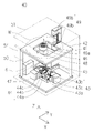
次に本発明の搬送装置2が備える雰囲気置換機能付きアライナ40の一実施形態について説明する。図9は本実施形態の雰囲気置換機能付きアライナ40(以下、「アライナ40記載する」を示す斜視図であり、図10はその断面図である。本実施形態のアライナ40は、不活性ガス雰囲気中でウエハWの中心点の位置のずれ量と、ノッチやオリエンテーションフラットといったウエハ外周縁に形成された切欠き部の位置とを検出して、予め設定された所定の位置に正確に位置決めするものである。本実施形態のアライナ40は、上部にウエハ仮置き台41が立設された上面プレート42と、その上面プレート42の下部に配置され、互いに直交する位置に配置されるX軸移動機構43とY軸移動機構44とを備えていて、これらのX軸移動機構43およびY軸移動機構44によって、上面プレート42の下方に配置される昇降機構45をXY平面内で移動させることが出来る。また、昇降機構45の昇降台にはスピンドル46とスピンドル上に載置されるウエハWを水平面内で回転させるためのスピンドル駆動モータ48が備えられていて、このモータ48の、鉛直方向に延在する出力軸は、スピンドル46の下部に設けられる回転軸と連結されている。
Next, an embodiment of the
スピンドル46は、ウエハWを水平に載せるウエハ載置台であり、スピンドル46上に水平に置かれたウエハWを吸着保持するための吸着孔46aが形成されていて、吸着孔46aは配管部材を介して不図示の真空源と接続されている。真空源と吸着孔46aとを連通させる配管部材の途中には不図示のウエハ保持用電磁弁が配置されていて、このウエハ保持用電磁弁の作動はアライナ制御部6によって制御される。なお、本実施形態のフィンガ18は真空の吸着力によってウエハWを保持する形態としているが、それ以外にも、クランプといった公知の保持手段による保持も十分可能である。アライナ制御部6は予め記憶されている制御プログラムと各種制御データに則って不活性ガスの制御を行う。制御データには不活性ガスの供給タイミングや、供給時間等のデータが含まれる。また、アライナ40に酸素濃度や不活性ガスの濃度を測定するセンサを設け、このセンサの検出値により不可性ガスの供給タイミングを調節する構成としても良い。さらに、不活性ガスの供給ラインを大流量供給ラインと小流量供給ラインというように複数設け、センサの検出値によって供給流量を切換える構成としてもよい。
The
X軸移動機構43は下面プレート47に固定され、Y軸移動機構44が載置された移動子をX軸方向に案内するスライドガイド43aと、スライドガイド43aに対して平行に配置され、移動子と螺合するボールネジ機構43bと、ボールネジ機構43bを駆動させるモータ43cとで構成される。また、Y軸移動機構44は、昇降機構45が載置された移動子をY軸方向に案内するスライドガイド44aと、スライドガイド44aに対して平行に配置され、移動子と螺合するボールナット44bと、ボールナットをY軸方向に延在する回転軸を回転中心として回転させるモータ44cとで構成される。昇降機構45は、スピンドル駆動モータ48が固定された移動子を鉛直方向、すなわちZ軸方向に案内するスライドガイドと、スライドガイドに対して平行に配置され、移動子と螺合するボールナットと、ボールナットをZ軸方向に延在する回転軸を回転中心として回転させるモータとで構成される。これら、X軸駆動機構43、Y軸駆動機構44、昇降機構45、及びスピンドル駆動モータ48はスピンドル駆動手段を構成している。なお、スピンドル駆動手段を構成する各モータは、全て回転軸の角度制御が可能なステッピングモータが使用されていて、各モータの作動はアライナ制御部6によって制御されている。
The
上面プレート42の切り欠かれた部分には、スピンドル46上のウエハWの周辺部を上下から挟むようにラインセンサ49が備えられている。このラインセンサ49は、直線状に配置される複数の発光部を備える投光器49aと、直線状に配置される複数の受光部を備える受光器49bとを、ウエハWの下方と上方とに互いに対向するように、かつ、発光部から照射される検出光の光軸がスピンドル46上に配置されるウエハWの移動方向に対して垂直になるように配置されている。このラインセンサ49は、スピンドル46の回転軸線に対するウエハW中心の偏心量と偏心方向を、投光器49aから照射される検出光がウエハW外周縁によって遮られる様子を受光器49bが検出する検出値によって測定するものであり、受光器49bによる測定値は、アライナ制御部6に電気信号として送信され、アライナ制御部6によって演算処理される。一般的にウエハWはFOUP19に収納されている状態から搬送ロボット30によって搬送されるまでに設計上の所定の位置からずれている場合が多く、搬送ロボット30によってスピンドル46上に載置されたウエハWは、スピンドル46の回転軸線に対して偏心して載置されるので、アライナ40は、スピンドル46上のウエハWを回転させて偏心量を検出し、アライナ制御部6により、予め定められた適切なウエハW中心位置にウエハWの実際の中心点位置が位置するように、ウエハWを水平方向に移動させるとともに、予め定められた適切な切欠き部位置に実際の切欠き部位置が位置するようにウエハWを回転させる。
A
本実施形態のアライナ40には、スピンドル駆動手段が配置されるアライナ40内部に配置される各機構を覆うようにカバー50が取り付けられている。このカバー50によりスピンドル駆動手段の駆動部分から発生した塵埃がアライナ40の外部に流出することを防いでいる。また、本実施形態のアライナ40の下面プレート47には不図示の開口が設けられていて、後述する不活性ガスや一般大気がこの開口から置換容器51の外部へと流出するので、置換容器51の内部を短時間で不活性ガス雰囲気に置換することが出来る。また、本実施形態のアライナ40の下面プレート47に、アライナ40の内部空間に滞留する空気を排出する排気ファンを備える形態としても良い。この排気ファンは、アライナ40に形成された開口を介して、アライナ40の内部空間に滞留する空気をアライナから外部に排出する。上記構成により、スピンドル46上に載置されるウエハWは、スピンドル駆動手段から発生する塵埃に汚染されることは無くなる。
A
さらに、本実施形態のアライナ40は、内部空間を不活性ガス雰囲気に置換することが出来る置換容器51の内部空間に配置されている。図10を参照。本実施形態の置換容器51は、天井部に不活性ガスを噴出するノズル52と、搬送ロボット30がアライナ40との間でウエハWを搬送するための開口53と、この開口53を閉鎖する蓋54とを備えている。ノズル52の噴出口には、チューブ部材やノズル52の内部に付着している不純物や塵埃を除去するフィルタが備えられていて、こういった塵埃等がウエハWを汚染することを防止している。なお、蓋54と置換容器51開口53周縁の壁面とは接触することなく、微小な隙間54aが設けられている。これにより、蓋54と開口53周縁の壁面とが接触することによる塵埃の発生を防止することができる。さらに、置換容器51内部に残留している大気はノズル52から供給される不活性ガスによりこの隙間54aを通って置換容器51の外部に押し出されるので、置換容器51の内部を短時間で不活性ガス雰囲気に置換することが可能になる。また、置換が終了した後も置換容器51内に不活性ガスを供給することにより、不活性ガスが隙間54aから容器外部へと流出していき、この外部へ流出する不活性ガスがシール部材の役割をして、塵埃等が置換容器51の内部に侵入することを防止している。
Furthermore, the
蓋54は、モータやエアシリンダといった公知の駆動手段により駆動される。蓋54の開閉制御はアライナ制御部6によって行われる。蓋54は、アライメントのために搬送ロボット30がウエハWをスピンドル46上に載置する場合、もしくは、アライメントが終了したウエハWを搬送ロボット30が次の工程に搬送する場合に開けられる。上記構成によりアライナ40は、不活性ガス雰囲気に維持されている置換容器51内でウエハWのアライメントを行うことが出来るので、アライメント中にウエハWの被処理面に不要な自然酸化膜が形成されるのを防止することが出来る。また、蓋54を開放した際に置換容器51内部の不活性ガスが外部に流出することで置換容器51内部の不活性ガス濃度が低下してしまう。そこで、アライナ制御部6は蓋54を開放する動作と併せて、アライナ40が備える電磁弁を作動させて、蓋54が開放されている間は通常よりも大流量の不活性ガスを供給させることで、置換容器51内部の不活性ガス濃度が低下することを防止している。なお、アライナ制御部6が不活性ガスの流量を切換えるタイミングは、蓋54の開閉のタイミングでも良いが、置換容器51内部に酸素濃度を検出するセンサを設け、このセンサの検出値が規定値を上回ると大流量の不活性ガスを自動的に供給し、センサの検出値が規定値を下回ると自動的に小流量に切り替えるようにしてもよい。また、本実施形態のアライナ40では、ヒンジ54bを中心に揺動可能な蓋54を備えているが、それ以外にも、例えば、置換容器51に対して隙間54aをあけて上下方向にスライド可能な蓋を備えることとしても良い。
The
次に、アライナ40とは別の実施形態について説明する。図11は本実施形態の雰囲気置換機能付きアライナ40-1を示す斜視図であり、図12(a)はその側面図である。本実施形態の雰囲気置換機能付きアライナ40-1(以下、「アライナ40-1」と記載する)では、アライナ40を覆う置換容器51を備えることなく、スピンドル46上でアライメント処理されているウエハWの被処理面に不活性ガスを吹き付けることでウエハWの被処理面の雰囲気を置換する。本実施形態のアライナ40-1は、ウエハWをスピンドル46上で保持した状態でウエハWの被処理面に向かって不活性ガスを噴出させるシャワープレート55を備えていて、これによってウエハWの被処理面に自然酸化膜が発生するのを防止するものである。
Next, another embodiment of the
シャワープレート55から噴出した不活性ガスは、シャワープレート55とウエハWとで形成される空間56に充満して、この空間56に残留している大気とともに外部へと流出していく。そして、不活性ガスを継続して供給することで、空間56内に残留していた大気や塵埃は空間の外部へと順次流出して、空間56内は不活性ガス雰囲気に置換される。また、空間56内に噴出された不活性ガスは、順次シャワープレート55とウエハWとの間の隙間から外部に流出することになり、この外部へ流出する不活性ガスの外向きの流れがエアシールの役割を果たすので、薄板状基板Wの上側の面である被処理面へ大気が侵入するのを防止することが出来る。これにより、薄板状基板Wの被処理面に自然酸化膜が生成されることを防止できる。シャワープレート55の噴出口には、チューブ部材やシャワープレート55の内部に付着している不純物や塵埃を除去するフィルタが備えられていて、こういった塵埃等によるウエハWの汚染を防止している。
The inert gas ejected from the
本実施形態のシャワープレート55は、パージ対象であるウエハWの直径と同等の直径を有する円盤状に形成されていて、支柱57によって支持されている。本実施形態のシャワープレート55は、不活性ガスの流路55dが形成されている上部材55aと不活性ガスを噴出させるための複数の貫通孔(噴出口)55cが形成されている下部材55bとの2つの部材から構成される。下部材55bに設けられている貫通孔(噴出口)55cの位置は、上部材55aと下部材55bとを貼り合せた際に流路55dと連通する位置に配置されている。これにより、流路55d内に供給された不活性ガスは、貫通孔55cから半導体ウエハWの被処理面に向かって噴出する。また、上部材55aには流路55dと連通する位置に継手37が取り付けられていて、不活性ガスを流通させるチューブ部材38が不図示の電磁弁を経由して不活性ガス供給源に接続される。また、シャワープレート55は、ウエハWの直径と同等の直径を有しているので、FFU13からの清浄空気のダウンフローを遮断しながらウエハWの被処理面全体に不活性ガスを供給うることが出来て、且つ、ウエハWの被処理面に万遍なく不活性ガスを噴出させることが出来る。なお、シャワープレート55は上記形状や大きさに限定されることは無く、ウエハWの直径よりも小さく形成したり、大きく形成したりすることも可能である。また、円盤状に限らず正方形や長方形、六角形といった多角形にすることも十分可能である。なお、本実施形態のシャワープレート55は、陽極酸化処理されたアルミニウムで形成されているが、本発明はこれに限定されることは無く、例えばセラミックやカーボン、エンジニアリングプラスチック等といった材料を用いることも可能である。
The
また、本実施形態のシャワープレート55には、中心部分から半径方向に延在する切欠き58が形成されていて、この切欠き58はアライナ40-1が備えるラインセンサ49の光軸が通過出来るように構成されている。この切欠き58により、シャワープレート55はラインセンサ49の光軸を遮ることなく、ウエハWの被処理面の雰囲気置換を行うことが出来る。また、シャワープレート55は、搬送ロボット30がアライナ40-1にアクセスする際に、フィンガ18の保持部18aとパージ部18bとに干渉しない位置に配置されていて、搬送ロボット30は、フィンガ18をスピンドル46とシャワープレート55との間の空間を通って、スピンドル46上にウエハWを載置したり、スピンドル46上のウエハWを取り出したりすることが出来る。上記構成によりアライナ40-1は、ウエハWを搬送ロボット30から受け取って、ウエハWのアライメントを行っている間、ウエハWの被処理面に不活性ガスを噴出させることが出来るので、ウエハWの被処理面に不要な自然酸化膜が形成されるのを防止することが出来る。
Further, the
さらに、第3の実施形態として、シャワープレート55を昇降移動させる昇降機構59を設けることも出来る。図12(b)は第3の実施形態であるアライナ40-2を示す断面図である。第3の実施形態の雰囲気置換機能付きアライナ40-2(以下、「アライナ40-2」と記載する)が備える昇降機構59は、シャワープレート55を鉛直方向に案内するリニアガイド59aと、シャワープレート55を昇降移動させる駆動源としてエアシリンダ59bを備えている。リニアガイド59aはガイドレールが鉛直方向に延在するようにブラケットを介して下面プレート47に固定されていて、レール上を移動する移動子にはシャワープレート55を支持する支柱57の下端部が固定されている。また、エアシリンダ59bは、シリンダロッドが鉛直方向に進退移動するように、シリンダ本体がブラケットを介して下面プレート47に固定されていて、シリンダロッドの先端部は支柱57に固定されている。また、エアシリンダ59bは、配管を介して不図示のエア供給源と接続されていて、さらに、配管の途中にはレギュレータと電磁弁が接続されている。電磁弁はアライナ制御部6と電気的に接続されていて、アライナ制御部6の動作信号により電磁弁は弁の開閉を行う。この弁の開閉によって、エアシリンダ59bのピストンロッドが進退動作することにより、シャワープレート55は鉛直方向に昇降移動する。
Furthermore, as a third embodiment, an elevating
アライナ制御部6は搬送ロボット30をアライナ40-2にアクセスさせようとする場合には、アライナ40-2に備えられる電磁弁を作動させて、エアシリンダ59bに空気を供給させてシャワープレート55をスピンドル46に対して離れた位置まで上昇移動させる。また、アライナ制御部6は、搬送ロボット30がアライナ40-2へウエハWの搬入が終了した時点で、アライナ40-2の電磁弁を作動させてエアシリンダ59aへの空気の供給を停止させて、シャワープレート55をウエハWに対して接近する位置まで下降移動させる。また、アライナ制御部6は、スピンドル46上にウエハWが載置されたことを検出すると、電磁弁を作動させてシャワープレート55からウエハWの被処理面に向かって不活性ガスを噴出させる。また、アライナ40-2のアライメント動作が終了して、搬送ロボット30がスピンドル46上のウエハWにアクセスする直前まで、アライナ制御部6はシャワープレート55からの不活性ガスの供給を続け、搬送ロボット30のフィンガ18がアライナ40-2に進出してくる時点で不活性ガスの供給を停止する。上記のように、搬送装置2に雰囲気置換機能付きアライナ40、40-1、40-2を備えることで、雰囲気置換機能付き搬送ロボット30によって被処理面を不活性ガス雰囲気に維持されて搬送されてきたウエハWの被処理面に自然酸化膜を生成させることなくアライメントすることが可能になる。さらに、アライメントを終了したウエハWは、雰囲気置換機能付き搬送ロボット30によって被処理面を不活性ガス雰囲気に維持されたまま処理装置3へと搬送されていくので、ミニエンバイロメント空間4内を不活性ガス雰囲気に維持せずとも、自然酸化膜を生成させることなくウエハWを処理装置に搬送することが可能になる。
When the
次に、本発明の搬送装置2が備える雰囲気置換機能付きバッファ装置60について説明する。本実施形態の雰囲気置換機能付きバッファ装置60(以下、「バッファ装置60」と記載する)はミニエンバイロメント空間4内に配置され、ウエハWの処理に要する時間の差によって生じるウエハ搬送の待ち時間を緩和するために、ウエハWを一時的に保管する装置である。なお、処理装置3の処理にかかる時間が比較的短くウエハ搬送の待ち時間が発生しないものには、基本的にバッファ装置60を備える必要は無い。処理装置3の処理にかかる時間が長い場合、長い待ち時間が発生して、ウエハWは一般大気に触れることで被処理面に自然酸化膜が形成されてしまう。そこで、バッファ装置60のウエハWを収納する空間を不活性ガス雰囲気に維持することで、ウエハW表面の自然酸化膜の形成を抑制する。
Next, the
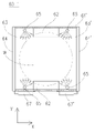
図13は本実施形態のバッファ装置60を示す図であり、図14はその断面図である。本実施形態のバッファ装置60は、ウエハWが収納される空間を形成する箱状の容器61と、ウエハWを上下方向に間隔を空けて載置する複数の棚板62と、それぞれの棚板62にウエハWを搬入・搬出するため容器に設けられた開口63と、この各開口63を閉鎖するための複数のシャッター64と、容器61の内部に不活性ガスを供給するノズル65とを備えている。
FIG. 13 is a diagram showing a
本実施形態のバッファ装置60を形成する箱状の容器61は、ステンレススチール製で、直方体に成形されている。バッファ装置60の搬送ロボット30に対向する面には開口63が形成されていて、この開口63を介して搬送ロボット30は、保持しているウエハWを容器61の内部に搬送したり、バッファ装置60の内部に保管されているウエハWを搬出したりする。また、バッファ装置60には開口63を閉鎖するシャッター64が備えられていて、容器61内部に充満している不活性ガスが容器61の外部に流出することを防止している。各シャッター64の上部にはヒンジが備えられており、このヒンジの水平方向に延在する回転軸を回転中心として回動するように構成されている。また、各シャッター64には、それぞれのシャッター64を開閉するための駆動源であるエアシリンダ67のピストンロッド先端が連結されていて、各エアシリンダ67のシリンダ本体は容器61に回転可能に取り付けられている。また、エアシリンダ67は、配管66を介して不図示のエア供給源と接続されていて、さらに、配管の途中にはレギュレータと電磁弁が接続されている。電磁弁はバッファ制御部7と電気的に接続されていて、バッファ制御部7の動作信号により電磁弁は弁の開閉を行う。この弁の開閉によって、エアシリンダ67のピストンロッドが進退動作することにより、シャッター64は容器61の壁面に対して回動して、開口63を開閉する。
A box-shaped
箱状の容器61の内部には、ウエハWを載置する複数の棚板62が、所定の間隔を空けて鉛直方向に棚段状に配置されている。棚板62は容器61内の対向する位置に配置され、対抗する一対の棚板62でウエハWを水平な姿勢で支持する。各シャッター64の配置は、この各棚にアクセスする搬送ロボット30のフィンガ18が通過可能な位置になるようにそれぞれ配置されていて、目的の棚板62に保管されているウエハWにアクセスしようとする場合、対応するシャッター64だけを開扉するだけでよい。上記構成とすることで、ウエハWにアクセスするための開口63の面積を最小限に抑えることが出来るので、容器61の内部に充満した不活性ガスの外部への流出を最低限に抑えることが出来る。
Inside the box-shaped
バッファ装置60の容器61内に不活性ガスを供給するノズル65は、開口63とは反対側の容器61後方に備えられている。本実施形態のノズル65は多数の噴出口が形成された円筒状の部材であり、上部には継手37が取り付けられていて、不活性ガスを流通させるチューブ部材が不図示の電磁弁を経由して不活性ガス供給源に接続されている。電磁弁はバッファ制御部7と電気的に接続されていて、バッファ制御部7の動作信号により電磁弁は弁の開閉を行い、不活性ガスの供給と停止を切換える。また、ノズル65の内部には、チューブ部材や継手37等の内部に付着している不純物や塵埃を除去するフィルタが備えられていて、こういった塵埃等がウエハWを汚染することを防止している。バッファ制御部7は予め記憶されている制御プログラムと各種制御データに則って不活性ガスの制御を行う。制御データには不活性ガスの供給タイミングや、供給時間等のデータが含まれる。また、バッファ装置60の容器61内に酸素濃度や不活性ガスの濃度を測定するセンサを設け、このセンサの検出値により不可性ガスの供給タイミングを調節する構成としても良い。さらに、不活性ガスの供給ラインを大流量供給ラインと小流量供給ラインというように複数設け、センサの検出値によって供給流量を切換える構成としてもよい。
A
また、容器61の底面に排気口が設けることで、容器61内に残留する一般大気はこの排気口を介して、バッファ装置60の外部へと流出することとなり、容器61内の雰囲気置換が効率よく行われる。なお、不活性ガスを供給するノズル65は、開口63とは反対側の容器61後方に備えることに限定されることは無く、ウエハWを支持する棚板62が配置される側面に設けてもよい。バッファ装置60が備えるノズル65の他の実施形態として、ノズル65は対向する位置に配置される棚板62の両側面にそれぞれ配置される。上記構成とすることで、ノズル65を一つしか備えない第1の実施形態に比べて、各ウエハWの被処理面に対して万遍なく不活性ガスを供給することが可能になる。
In addition, since the exhaust port is provided on the bottom surface of the
次に、バッファ装置60の第2の実施形態について説明する。図15は本実施形態の雰囲気置換機能付きバッファ装置60-1を示す図である。本実施形態の雰囲気置換機能付きバッファ装置60-1(以下、「バッファ装置60-1」と記載する)は、ウエハWにアクセスするための開口63の対向面にも開口63´を設け、さらに開口63と同様に、この開口63´を閉鎖する複数のシャッター64´が備えられていて、各シャッター64´の上部にはヒンジが備えられており、このヒンジの水平方向に延在する回転軸を回転中心として回動するように構成されている。また、各シャッター64´の開閉はエアシリンダ67´で行うように構成されている。上記構成とすることで、搬送ロボット30は、容器61´内部の棚板62に載置されるウエハWに対して、対向して配置される各開口63、63´のいずれからでもアクセスすることが可能になる。
Next, a second embodiment of the
また、本実施形態のアライナ60-2は、搬送ロボット30やアライナ40-1が備えるような板状のシャワープレート87を内部に備えることも可能である。図16は本発明の他の実施形態であるバッファ装置60-2を示す断面図である。本実施形態のバッファ装置60-2にはウエハWを支持する各棚板62のそれぞれの上方にシャワープレート87が配置されている。シャワープレート87は各棚板62に載置されるウエハWの被処理面に向かって不活性ガスを噴出させるものであり、これによってウエハWの被処理面に自然酸化膜が発生するのを防止する。シャワープレート87から噴出した不活性ガスは、シャワープレート87とウエハWとで形成される空間88に充満した後、この空間88に残留している大気とともにバッファ装置60-2の外部へと流出していく。なお、シャワープレート87の噴出口には、チューブ部材やシャワープレート87の内部に付着している不純物や塵埃を除去するフィルタが備えることとしてもよく、これにより、塵埃等がウエハWを汚染することを防止している。
Further, the aligner 60-2 of the present embodiment can be internally equipped with a plate-
本実施形態のシャワープレート87は、パージ対象であるウエハWの直径と同等の直径を有する円盤状に形成されていて、容器61の壁面によって支持されている。シャワープレート87は、不活性ガスの流路が形成されている上部材と不活性ガスを噴出させるための複数の貫通孔(噴出口)が形成されている下部材との2つの部材から構成される。下部材に設けられている貫通孔(噴出口)の位置は、上部材に形成された流路と連通する位置に配置されていて、流路内に供給された不活性ガスは、貫通孔から半導体ウエハWの被処理面に向かって噴出する。また、それぞれのシャワープレート87には各流路と連通する継手89が取り付けられていて、不活性ガスを流通させる配管66が不図示の電磁弁を経由して不活性ガス供給源に接続される。なお、シャワープレート87の形状は円盤状に限らず正方形や長方形、六角形といった多角形にすることも十分可能である。なお、本実施形態のシャワープレート87は、陽極酸化処理されたアルミニウムや、セラミック、カーボン、エンジニアリングプラスチック等といった材料が用いられる。
The
さらに、棚板62の代わりに、流路69が形成された棚部材72をバッファ装置60の内部空間に配置して、棚部材72に形成される噴出口73からウエハWの被処理面に向かって不活性ガスを噴出させる形態であってもよい。図17は不活性ガスの流路69が形成された棚部材72の断面と、棚部材72を備えるバッファ装置60-3を示す断面図である。本実施形態の棚部材72は、鉛直方向に延在する柱部72aと、柱部72aから水平方向に突出して形成される棚部72bとで構成される。バッファ装置60-3の内部に搬送されたウエハWはこの棚部72bの上面に配置される。棚部材72に形成される流路69の一端には継手37が取り付けられていて、不活性ガスを流通させるチューブ部材が不図示の電磁弁を経由して不活性ガス供給源に接続されている。また、流路69の先端の噴出口73には、板状のフィルタ74が固定されていて、流路69に供給された不活性ガスは、フィルタ74を形成するガラス繊維の微小な隙間を通って容器61内に供給される。フィルタ74を介して不活性ガスを供給することで、容器61の隅に滞留する塵埃を巻き上げることなく、比較的大量のガスを容器61の内部に供給することが出来る。また、チューブ部材や棚部材72の内部に付着している不純物や塵埃がウエハWを汚染することを防止している。上記構成のように、棚部材72から不活性ガスを噴出させる構成とすることで、容器61の内部にノズル65を設ける必要がないので、容器61をコンパクトに形成することが可能になる。なお、両側に開口63、63´を有するバッファ装置60-1、60-3は、内部に2台の搬送ロボット30-1a、30-1bが互いに対向する位置に設けられる搬送装置2´に好適に用いられる。
Furthermore, instead of the
また、上記のバッファ装置60-1では、棚板62上に載置されるウエハWのそれぞれの被処理面に向かって不活性ガスを噴出させるシャワープレート87を備える形態としているが、こういった形態は、バッファ装置60-1以外にロードロックチャンバ12やその他のウエハ受渡し用装置にも適用可能である。図18は本発明の一実施形態である雰囲気置換機能付きロードロックチャンバ12-1を示す断面図である。本実施形態の雰囲気置換機能付きロードロックチャンバ12-1(以下、「ロードロックチャンバ12-1」と記載する)は、真空容器90と、ウエハWを載置する棚板62-1と、棚板62-1に載置されるウエハWに被処理面に向かって不活性ガスを噴出させるシャワープレート87-1と、棚板62-1とシャワープレート87-1を鉛直方向に支持する支持部材91と、支持部材91を鉛直方向に昇降移動させる昇降機構102を備えている。本実施形態のロードロックチャンバ12-1は、搬送装置2と搬送チャンバ8との間でウエハWを中継するための装置であり、真空容器90の搬送装置2に対向する面には、ウエハWが通過可能な開口92が設けられていて、この開口は、ゲートバルブ93によって気密に閉鎖可能な構造となっている。また、真空容器90の搬送チャンバ8に対向する面には、ウエハWが通過可能な開口94が設けられていて、この開口は、ゲートバルブ95によって気密に閉鎖可能な構造となっている。ゲートバルブ93、95は、それぞれに対応する開口92、94を気密に閉塞可能な蓋部材であり、ゲートバルブ93によってロードロックチャンバ12-1とミニエンバイロメント空間4との間に設けられる開口92を閉鎖および開放することが出来る。また、ゲートバルブ95によってロードロックチャンバ12-1と搬送チャンバ8とロードロックチャンバ12-1との間に設けられる開口92を閉鎖及び開放することが出来る。
Further, the buffer device 60-1 described above is provided with a
また、真空容器90の内部空間は排気管96を介して不図示の真空ポンプと連通している。また、排気管96の途中にはバルブ97が備えられていて、真空容器90内部の真空度により開度を調節することが可能になっている。さらに、シャワープレート87-1は配管98を介して不図示の不活性ガス供給源と接続されている。また、配管98の途中にはバルブ99が備えられている。バルブ97とバルブ99はロードロック制御部100と電気的に接続されていて、ロードロック制御部100から送信される信号により、バルブ97とバルブ99とは、弁の開閉動作を行う。
The internal space of the
搬送ロボット30によって搬送装置2からウエハWが搬送されて来る場合、ロードロック制御部100はバルブ99を作動させて真空容器90の内部を不活性ガス雰囲気に維持しておく。さらに、ウエハWが搬送ロボット30によって棚板62-1に載置される時にもシャワープレート87-1から不活性ガスを噴出させておき、ウエハWの被処理面に酸化膜が生成されるのを防止する。ウエハWをロードロックチャンバ12-1まで搬送するには、本発明の一実施形態である雰囲気置換機能付き搬送ロボット30を使用することで、搬送時のウエハWに酸化膜が生成されることは防止できる。しかし、ウエハWが搬入される時、真空容器90内は不活性ガス雰囲気に維持されているが、ゲートバルブ93が開けられ、搬送装置2の内部の空気が真空容器90の内部空間に流入するので、内部空間の酸素濃度は若干上昇してしまう。そこで、搬入されたウエハWの被処理面にシャワープレート87-1から不活性ガスを噴出させることで、不要な酸化膜の生成を防止することが出来るのである。なお、ウエハWの搬送が終了したら、ゲートバルブ93が閉じられて、真空容器90の内部空間は真空引きされるが、この真空引きの際には不活性ガスの供給が停止されることは言うまでもない。
When the wafer W is transferred from the
また、本実施形態のロードロックチャンバ12-1は、真空容器90の内部空間を真空状態から大気圧に昇圧させて、ウエハWを搬送装置2側に搬出する際にも有効に作用する。搬送チャンバ8からウエハWが搬入される際には、真空容器90の内部空間は真空雰囲気に維持されている。ウエハWの搬入が完了するとゲートバルブ95が閉じられ、シャワープレート87-1から真空容器90の内部空間に供給される不活性ガスによって大気圧と同程度まで昇圧される。このとき、シャワープレート87-1は棚板62-1に載置されるウエハWに対して至近距離から不活性ガスを噴出させるので、ウエハWの被処理面に残留している反応ガスは除去される。さらに、被処理面は不活性ガスによって置換されるので、自然酸化膜が生成されることはなくなる。また、熱処理直後で余熱が残っているウエハWは、至近距離から噴出される不活性ガスによってより早く冷却される。
In addition, the load lock chamber 12-1 of the present embodiment effectively increases the internal space of the
なお、シャワープレート87-1はウエハWの近傍に配置されウエハWの被処理面に不活性ガスを噴出させることが重要であって、形状については、円盤状、矩形、楕円形といった様々な形状であって構わない。さらに、プレート状プレート形状以外にも、円柱状や半円形といった形状であっても構わない。また、シャワープレート87-1に加えて、ロードロックチャンバ12-1内部に不活性ガスを供給するノズル101を設け、ロードロックチャンバ12-1の内部を素早く昇圧させるように構成してもよい。
It is important that the shower plate 87-1 is arranged in the vicinity of the wafer W to eject the inert gas onto the surface of the wafer W to be processed. It doesn't matter if it is. Furthermore, other than the plate-shaped plate shape, a columnar shape or a semicircular shape may be used. Further, in addition to the shower plate 87-1, a
図19は2台の搬送ロボット30-1a、30-1bを備える搬送装置2´を含む処理システムA-1を上面から見た断面図であり、図20は搬送装置2´を正面から見た断面図である。本実施形態の搬送装置2´には、正面に2台の雰囲気置換機能付きロードポート20a、20bが搭載されていて、搬送装置2´の背面であって各ロードポート20a、20bと対向する位置には、2台の処理装置3a、3bが配置されている。また、搬送装置2´と処理装置3aとの間には、雰囲気置換機能付きロードロックチャンバ12-1aが配置され、搬送装置2´と処理装置3bとの間には、雰囲気置換機能付きロードロックチャンバ12-1bが配置されている。搬送装置2´の天井にはFFU13が配置されていて、FFU13から供給される清浄空気により、ミニエンバイロメント空間4´は常に清浄な雰囲気に維持される。また、ミニエンバイロメント空間4´には、2台の雰囲気置換機能付き搬送ロボット30-1a、30-1bが配置されている。各搬送ロボット30-1a、30-1bは、ミニエンバイロメント空間4内であって、対向して配置されるロードポート20aと処理装置3a、及びロードポート20bと3bそれぞれの中間位置に配置され、ロードポート20aと処理装置3aと搬送ロボット30-1a、及びロードポート20bと処理装置3bと搬送ロボット30-1bとは、それぞれY軸に平行な直線上に配置される。
FIG. 19 is a top cross-sectional view of a processing system A-1 including a transport device 2' having two transport robots 30-1a and 30-1b, and FIG. 20 is a front view of the transport device 2'. It is a sectional view. Two
2台の搬送ロボット30-1a、30-1bは所定の間隔をあけて配置されていて、2台の搬送ロボット30-1a、30-1bの間にはテーブル70が備えられている。さらに、このテーブル70上には2台の雰囲気置換機能付きアライナ40-1a、40-1bが固定されている。また、アライナ40-1a、40-1bの上方には、本実施形態の雰囲気置換機能付きバッファ装置60-1が配置されていて、この雰囲気置換機能付きバッファ装置60-1は、搬送装置2´の天井フレーム4aに固定された支柱71によって上方から保持されている。なお、本実施形態の搬送装置2´が備える2台の雰囲気置換機能付きアライナ40a、40bは、ウエハWを保持するスピンドル46の上方にシャワープレート55を備えるものであり、左右に配置される各雰囲気置換機能付き搬送ロボット30-1a、30-1bがアクセスできる位置に配置されている。
The two transport robots 30-1a and 30-1b are arranged at a predetermined interval, and a table 70 is provided between the two transport robots 30-1a and 30-1b. Further, two aligners 40-1a and 40-1b with an atmosphere replacement function are fixed on the table 70. As shown in FIG. Moreover, above the aligners 40-1a and 40-1b, a buffer device 60-1 with an atmosphere replacement function of the present embodiment is arranged. It is held from above by a
上記構成の搬送装置2´により、一方の搬送ロボット30-1aは、一方のロードポート20aに載置されるFOUP19aからウエハWを取り出してアライナ40aに搬送した後、アライナ40aによってウエハWの正確な位置決めを行って、処理装置3aにウエハWを搬送する。処理装置3aによる処理が終了すると、搬送ロボット30-1aが処理装置3aからウエハWを取出して、バッファ装置60-1へと搬送する。バッファ装置60-1へと搬送されたウエハWは、もう一方の搬送ロボット30-1bによってバッファ装置60-1取り出され、アライナ40bによって正確に位置決めされた後、処理装置3bに搬送される。処理装置3bによる処理が終了すると、ウエハWは搬送ロボット3bによって、ロードポート20bに載置されるFOUP19bへと搬送される。
With the transfer device 2' configured as described above, one transfer robot 30-1a picks up a wafer W from the
上記バッファ装置60-1ではミニエンバイロメント空間4´内に吊り下げて配置されていたが、他の実施形態も可能である。図21は他の実施形態であるバッファ装置60-3を搭載する処理システムA-2を示す断面図である。本実施形態のバッファ装置60-3は、多数のウエハWを上下方向に所定の間隔を空けて載置するカセット77と、カセット77を昇降移動させるカセット昇降機構78と、カセット77とカセット昇降機構78とを覆うカバー79とを備えている。また、カバー79の搬送ロボット30-1a、30-1bに対向するそれぞれの面には、フィンガ18が通過可能な開口80a、80bが形成されていて、この各開口80a、80bは、それぞれシャッター機構81により閉鎖可能な構成となっている。
Although the buffer device 60-1 is suspended in the mini-environment space 4', other embodiments are possible. FIG. 21 is a sectional view showing a processing system A-2 equipped with a buffer device 60-3, which is another embodiment. The buffer device 60-3 of this embodiment includes a
各開口80a、80bは各搬送ロボット30-1a、30-1bがアクセス可能な高さに設定されていて、この各開口80a、80bに対してカセット77の所定の段のウエハWがカセット昇降機構78の作動によって昇降移動することで、各搬送ロボット30-1a、30-1bは所定のウエハWにアクセスすることが可能になる。また、カバー79の天井部分には、不活性ガスをバッファ装置60-3内部に供給するノズル82が備えられている。また、バッファ装置60-3の底部には不図示のスリットが設けられていて、バッファ装置60-3内部の一般大気は不活性ガスに押し出されることで、バッファ装置60-3内部の雰囲気が効率よく置換される。
Each of the openings 80a and 80b is set at a height that can be accessed by each of the transfer robots 30-1a and 30-1b. Each of the transfer robots 30-1a and 30-1b can access a predetermined wafer W by moving up and down by the operation of 78. FIG. Further, the ceiling portion of the
上記のように、バッファ装置60-3を搬送装置2の床面に固定する形態とすることして、カセット77を昇降移動可能な構成とすることで、ウエハWを収納するカセット77を大量のウエハWを収納できるようにすることが出来る。
As described above, the buffer device 60-3 is fixed to the floor surface of the
上記のように、雰囲気置換機能付きロードポート20、雰囲気置換機能付き搬送ロボット30、雰囲気置換機能付きアライナ40、雰囲気置換機能付きバッファ装置60、を備えることにより、ウエハWが留置及び移動する経路上を不活性ガスに置換された雰囲気に局所的に維持されているので、ミニエンバイロメント空間4´の全体を不活性ガス雰囲気に維持する必要は無くなる。さらに、本発明の各実施形態が備える不活性ガス供給ラインには、不活性ガスに混入していたり、配管の中に付着したりしている不純物や塵埃を除去するフィルタを備えることが望ましい。不活性ガス供給ラインにフィルタを備えることで、ロードポート20や搬送ロボット30等の各ユニットによってウエハWの被処理面は常に高清浄な不活性雰囲気に維持されるので、ミニエンバイロメント空間4、4´内部を高清浄な雰囲気に維持する必要が無くなる。すなわち、搬送装置2、2´に高価なFFU13を備える必要が無くなるので、大きなコストダウンが可能になる。
As described above, by providing the
本発明の搬送装置2、2´が備える雰囲気置換機能付き装置は、それぞれが制御部5、6、7、39を備え、個別に不活性ガスの噴出と停止の制御、及び各駆動機構の動作制御を行う構成となっている。また、搬送装置2、2´は、ウエハWを目的の位置まで搬送するために、搬送動作全体を制御するメイン制御ユニット68を備えている。図22は本発明の搬送装置2、2´の制御系統を示すブロック図である。メイン制御ユニット68は、少なくとも、半導体製造工場が備える上位側コンピュータ76、及び雰囲気置換機能付き装置が備える各制御部5、6、7、39と通信する通信モジュールと、中央演算処理装置、予め作成された制御プログラムや各種データを記憶する記憶装置、論理回路を備えている。メイン制御ユニット68は上位側コンピュータ76から受信した制御指令を基に、各雰囲気置換機能付き装置に対して動作指令を送信する。各雰囲気置換機能付き装置は、各制御部5、6、7、39に予め記憶された制御プログラムに則ってモータや電磁弁等を作動させて、所定の動作を行う。また、所定の動作が終了したらフィードバック信号をメイン制御ユニット68に送信する。各雰囲気置換機能付き装置から送信されるフィードバック信号を受信したメイン制御ユニット68は、予め記憶された制御プログラムの則って次の動作指令を送信する。こうした一連の動作によってウエハWは、被処理面を不活性ガ雰囲気に維持されながら所定の位置までに搬送される。
The devices with an atmosphere replacement function included in the
以上、本発明の実施形態を、図面を参照して詳しく説明してきたが、本発明は上記の実施形態に限定されるものではなく、本発明の要旨を逸脱しない範囲での変更等が可能である。例えば、本実施形態の雰囲気置換機能付きバッファ装置60、60-1、60-2にウエハWの検出センサを設け、棚板62上にウエハWが載置されている間に限り不活性ガスを供給する形態としても良い。さらに、ウエハWが移動する空間は全て清浄な不活性ガス雰囲気に維持されているので、搬送装置2、2´はFFU13を備えない形態としても良い。
Although the embodiments of the present invention have been described in detail with reference to the drawings, the present invention is not limited to the above embodiments, and modifications and the like are possible without departing from the gist of the present invention. be. For example, the
Claims (11)
前記半導体ウエハを保持して、前記半導体ウエハの被処理面の雰囲気を置換するフィンガを備える雰囲気置換機能付き搬送ロボットと、
前記半導体ウエハを保持して前記半導体ウエハの被処理面の雰囲気を置換する第1の雰囲気置換機能付きアライナとを備え、
半導体ウエハの被処理面の雰囲気を清浄な不活性ガス雰囲気に置換しながら前記半導体ウエハを搬送する搬送装置であって、
前記フィンガは、前記半導体ウエハを保持する保持部と前記半導体ウエハの被処理面に向かって不活性ガスを噴出するパージ部とを備え、
前記第1の雰囲気置換機能付きアライナは、
置換容器に収納されており、
前記半導体ウエハを保持して水平方向に回転させるスピンドルと、前記スピンドル上に保持される前記半導体ウエハの周縁を上下から挟み込むように配置されるラインセンサと、を備えており、
前記置換容器には、前記半導体ウエハを保持する前記フィンガが通過可能な開口が形成されており、
前記置換容器は、前記置換容器の内部空間に前記不活性ガスを噴出する第1のノズルと、 ヒンジによって揺動することで前記開口を閉鎖可能な蓋とを備え、
前記蓋は、前記開口周縁の壁面との間に微小な隙間を開けて前記開口を閉鎖し、
前記置換容器の前記内部空間に噴出された前記不活性ガスは、前記微小な隙間を介して前記置換容器の外部に流出する
ことを特徴とする搬送装置。
a load port with an atmosphere replacement function for placing a sealable container containing a semiconductor wafer and replacing the inside of the container with an inert gas atmosphere;
a transfer robot with an atmosphere replacement function that holds the semiconductor wafer and has a finger that replaces the atmosphere of the surface to be processed of the semiconductor wafer;
an aligner with a first atmosphere replacement function that holds the semiconductor wafer and replaces the atmosphere of the surface to be processed of the semiconductor wafer;
A transfer apparatus for transferring the semiconductor wafer while replacing the atmosphere of the surface to be processed of the semiconductor wafer with a clean inert gas atmosphere,
The finger includes a holding portion for holding the semiconductor wafer and a purge portion for ejecting an inert gas toward the surface to be processed of the semiconductor wafer,
The first aligner with an atmosphere replacement function,
housed in a replacement container,
a spindle that holds and rotates the semiconductor wafer in a horizontal direction; and a line sensor that is arranged to sandwich the peripheral edge of the semiconductor wafer held on the spindle from above and below;
The replacement container is formed with an opening through which the finger holding the semiconductor wafer can pass,
The replacement container includes a first nozzle that ejects the inert gas into the internal space of the replacement container, and a lid that can close the opening by swinging with a hinge,
The lid closes the opening with a minute gap between the lid and the wall surface of the opening periphery,
The conveying device, wherein the inert gas ejected into the internal space of the replacement container flows out of the replacement container through the minute gap.
前記半導体ウエハを保持して、前記半導体ウエハの被処理面の雰囲気を置換するフィンガを備える雰囲気置換機能付き搬送ロボットと、
前記半導体ウエハを保持して前記半導体ウエハの被処理面の雰囲気を置換する第2の雰囲気置換機能付きアライナとを備え、
半導体ウエハの被処理面の雰囲気を清浄な不活性ガス雰囲気に置換しながら前記半導体ウエハを搬送する搬送装置であって、
前記フィンガは、前記半導体ウエハを保持する保持部と前記半導体ウエハの被処理面に向かって不活性ガスを噴出するパージ部とを備え、
前記第2の雰囲気置換機能付きアライナは、
前記半導体ウエハを保持して水平方向に回転させるスピンドルと、
前記スピンドル上に保持される前記半導体ウエハの周縁を上下から挟み込むように配置されるラインセンサと、
前記スピンドル上に保持される前記半導体ウエハの前記被処理面に向かって前記不活性ガスを噴出する第1のシャワープレートを備え、
前記第1のシャワープレートは、前記ラインセンサの光軸が通過する位置には、前記光軸が通過可能な切り欠きが形成されている
ことを特徴とする搬送装置。
a load port with an atmosphere replacement function for placing a sealable container containing a semiconductor wafer and replacing the inside of the container with an inert gas atmosphere;
a transfer robot with an atmosphere replacement function that holds the semiconductor wafer and has a finger that replaces the atmosphere of the surface to be processed of the semiconductor wafer;
an aligner with a second atmosphere replacement function that holds the semiconductor wafer and replaces the atmosphere of the surface to be processed of the semiconductor wafer;
A transfer apparatus for transferring the semiconductor wafer while replacing the atmosphere of the surface to be processed of the semiconductor wafer with a clean inert gas atmosphere,
the finger includes a holding portion for holding the semiconductor wafer and a purge portion for ejecting an inert gas toward the surface to be processed of the semiconductor wafer,
The second aligner with atmosphere replacement function,
a spindle for holding and horizontally rotating the semiconductor wafer;
a line sensor arranged to sandwich the peripheral edge of the semiconductor wafer held on the spindle from above and below;
a first shower plate for ejecting the inert gas toward the surface to be processed of the semiconductor wafer held on the spindle;
The first shower plate has a notch through which the optical axis of the line sensor passes.
A conveying device characterized by:
2. The conveying apparatus according to claim 1, wherein said first aligner with atmosphere replacement function is provided with a filter for removing dust contained in said inert gas .
3. The conveying apparatus according to claim 2, wherein said second aligner with atmosphere replacement function is provided with a filter for removing dust contained in said inert gas .
5. The second aligner with an atmosphere replacement function according to claim 2 or 4, further comprising a shower plate elevating mechanism for vertically moving the first shower plate. transport device .
前記搬送装置はさらに第1の雰囲気置換機能付きバッファ装置を備え、
前記第1の雰囲気置換機能付きバッファ装置は、
前記半導体ウエハを載置する棚板と、前記棚板に対応する位置に配置される開口と、
前記不活性ガスを噴出する第2のノズルと、
前記開口を閉鎖可能な蓋とを備える置換容器を備えることを特徴とする搬送装置。
The conveying device according to any one of claims 1 to 5,
The transport device further comprises a buffer device with a first atmosphere replacement function,
The first buffer device with atmosphere replacement function includes:
a shelf plate on which the semiconductor wafer is placed; an opening arranged at a position corresponding to the shelf plate;
a second nozzle for ejecting the inert gas;
A conveying device comprising a replacement container including a lid capable of closing the opening .
バッファ制御部を備えており、前記バッファ制御部は前記開口を開放している間、前記第2のノズルから噴出される不活性ガスの流量を大きくすることを特徴とする、請求項6に記載の搬送装置。
The first buffer device with atmosphere replacement function includes:
7. The apparatus according to claim 6, further comprising a buffer control unit, wherein the buffer control unit increases the flow rate of the inert gas ejected from the second nozzle while the opening is open. transport device .
前記棚板が形成されるカセットと、前記カセットを昇降移動させるカセット昇降機構と、前記カセットと前記カセット昇降機構とを覆うカバーとを備えることを特徴とする、請求項6もしくは請求項7のいずれか一項に記載の搬送装置。
The first buffer device with atmosphere replacement function includes:
8. The apparatus according to claim 6, further comprising: a cassette on which said shelf plate is formed; a cassette elevating mechanism for vertically moving said cassette; and a cover for covering said cassette and said cassette elevating mechanism. or the conveying device according to claim 1 .
前記搬送装置はさらに第2の雰囲気置換機能付きバッファ装置を備え、
前記第2の雰囲気置換機能付きバッファ装置は、
前記半導体ウエハを載置する棚板と、前記棚板に対応する位置に配置される開口と、
前記棚板の上方に配置されており、前記棚板に載置される前記半導体ウエハの被処理面に不活性ガスを噴出する第2のシャワープレートとを備えることを特徴とする搬送装置。
The conveying device according to any one of claims 1 to 5,
The transport device further includes a buffer device with a second atmosphere replacement function,
The second buffer device with atmosphere replacement function includes:
a shelf plate on which the semiconductor wafer is placed; an opening arranged at a position corresponding to the shelf plate;
and a second shower plate arranged above the shelf plate for ejecting inert gas onto the surface to be processed of the semiconductor wafer placed on the shelf plate .
前記搬送装置はさらに雰囲気置換機能付きロードロックチャンバを備え、
前記雰囲気置換機能付きロードロックチャンバは、
前記半導体ウエハを載置する棚板と、
前記雰囲気置換機能付きロードロックチャンバの内部空間とミニエンバイロメント空間とを連通する第1の開口と、
前記雰囲気置換機能付きロードロックチャンバの内部空間と搬送チャンバの内部空間とを連通する第2の開口と、
前記第1の開口を閉鎖可能な第1の蓋部材と、前記第2の開口を閉鎖可能な第2の蓋部材と、
前記棚板上に載置された前記半導体ウエハの被処理面に向かって前記不活性ガスを噴出する第3のシャワープレートとを備えることを特徴とする搬送装置。
The conveying device according to any one of claims 1 to 9,
The transfer device further comprises a load lock chamber with an atmosphere replacement function,
The load lock chamber with atmosphere replacement function is
a shelf plate on which the semiconductor wafer is placed;
a first opening communicating between the internal space of the load lock chamber with atmosphere replacement function and the mini-environment space;
a second opening communicating between the internal space of the load lock chamber with the atmosphere replacement function and the internal space of the transfer chamber;
a first lid member capable of closing the first opening; a second lid member capable of closing the second opening;
and a third shower plate for ejecting the inert gas toward the surface to be processed of the semiconductor wafer placed on the shelf .
前記雰囲気置換機能付きロードロックチャンバは棚段状に前記半導体ウエハを載置する前記棚板を備え、
前記第3のシャワープレートは、前記棚段状に載置される前記半導体ウエハのそれぞれの上方に配置されることを特徴とする搬送装置。
A conveying device according to claim 10, wherein
The load-lock chamber with an atmosphere replacement function includes the shelf board on which the semiconductor wafer is placed in a shelf shape,
The conveying apparatus, wherein the third shower plate is arranged above each of the semiconductor wafers placed on the shelf .
Priority Applications (7)
| Application Number | Priority Date | Filing Date | Title |
|---|---|---|---|
| JP2018133067A JP7136612B2 (en) | 2018-07-13 | 2018-07-13 | Conveyor with local purge function |
| TW107129920A TWI765088B (en) | 2018-07-13 | 2018-08-28 | Transport system having local purge function |
| US17/258,872 US20210327737A1 (en) | 2018-07-13 | 2018-08-29 | Transport device having local purge function |
| KR1020207038092A KR102626528B1 (en) | 2018-07-13 | 2018-08-29 | Conveying device with local purge function |
| EP18926100.1A EP3796368B1 (en) | 2018-07-13 | 2018-08-29 | Transport device having local purge function |
| PCT/JP2018/031894 WO2020012669A1 (en) | 2018-07-13 | 2018-08-29 | Transport device having local purge function |
| CN201880095238.3A CN112424923B (en) | 2018-07-13 | 2018-08-29 | Conveying device with local cleaning function |
Applications Claiming Priority (1)
| Application Number | Priority Date | Filing Date | Title |
|---|---|---|---|
| JP2018133067A JP7136612B2 (en) | 2018-07-13 | 2018-07-13 | Conveyor with local purge function |
Publications (2)
| Publication Number | Publication Date |
|---|---|
| JP2020013814A JP2020013814A (en) | 2020-01-23 |
| JP7136612B2 true JP7136612B2 (en) | 2022-09-13 |
Family
ID=69142298
Family Applications (1)
| Application Number | Title | Priority Date | Filing Date |
|---|---|---|---|
| JP2018133067A Active JP7136612B2 (en) | 2018-07-13 | 2018-07-13 | Conveyor with local purge function |
Country Status (7)
| Country | Link |
|---|---|
| US (1) | US20210327737A1 (en) |
| EP (1) | EP3796368B1 (en) |
| JP (1) | JP7136612B2 (en) |
| KR (1) | KR102626528B1 (en) |
| CN (1) | CN112424923B (en) |
| TW (1) | TWI765088B (en) |
| WO (1) | WO2020012669A1 (en) |
Families Citing this family (4)
| Publication number | Priority date | Publication date | Assignee | Title |
|---|---|---|---|---|
| JP7163199B2 (en) * | 2019-01-08 | 2022-10-31 | 東京エレクトロン株式会社 | Substrate processing equipment |
| JP7156332B2 (en) * | 2020-05-21 | 2022-10-19 | 株式会社安川電機 | Conveying Device, Conveying Method and Conveying System |
| EP4163061A4 (en) | 2020-06-05 | 2024-07-24 | Rorze Corporation | WAFER TRANSFER DEVICE AND WAFER TRANSFER METHOD |
| JP2023006718A (en) | 2021-06-30 | 2023-01-18 | 株式会社荏原製作所 | Transfer device and substrate processing device |
Citations (11)
| Publication number | Priority date | Publication date | Assignee | Title |
|---|---|---|---|---|
| JP2000012647A (en) | 1998-06-19 | 2000-01-14 | Sumitomo Eaton Noba Kk | Device and method for carrying wafer |
| JP2003188229A (en) | 2001-12-18 | 2003-07-04 | Hitachi Kasado Eng Co Ltd | System and method for manufacturing wafer |
| JP2004119627A (en) | 2002-09-25 | 2004-04-15 | Hitachi Kokusai Electric Inc | Semiconductor device manufacturing apparatus |
| JP2009032877A (en) | 2007-07-26 | 2009-02-12 | Tokyo Electron Ltd | Substrate conveyance module and substrate processing system |
| JP2013207152A (en) | 2012-03-29 | 2013-10-07 | Dainippon Screen Mfg Co Ltd | Thermal treatment equipment and thermal treatment method |
| WO2013179904A1 (en) | 2012-05-28 | 2013-12-05 | 東京エレクトロン株式会社 | Transportation mechanism, transportation method, and processing system |
| JP2014203918A (en) | 2013-04-03 | 2014-10-27 | 有限会社アクセス | Substrate transport box and substrate transport apparatus |
| JP2015065358A (en) | 2013-09-26 | 2015-04-09 | 株式会社Screenホールディングス | Heat treatment device |
| JP2016086161A (en) | 2014-10-24 | 2016-05-19 | ラム リサーチ コーポレーションLam Research Corporation | Buffer station with single exit-flow direction |
| JP2017128796A (en) | 2016-01-15 | 2017-07-27 | 東京エレクトロン株式会社 | Vacuum processing apparatus and operating method of vacuum processing apparatus |
| JP2017108112A5 (en) | 2016-10-07 | 2020-01-23 |
Family Cites Families (11)
| Publication number | Priority date | Publication date | Assignee | Title |
|---|---|---|---|---|
| CA2043266A1 (en) * | 1990-09-24 | 1992-03-25 | Gary Hillman | Wafer transfer device |
| JPH09330972A (en) * | 1996-06-13 | 1997-12-22 | Dainippon Screen Mfg Co Ltd | Substrate transporting device |
| JP4054248B2 (en) * | 2002-11-18 | 2008-02-27 | 大日本スクリーン製造株式会社 | Substrate processing equipment |
| JP5154008B2 (en) * | 2004-11-10 | 2013-02-27 | 株式会社Sokudo | Substrate processing apparatus and substrate processing method |
| JP2009170740A (en) * | 2008-01-18 | 2009-07-30 | Rorze Corp | Transfer device |
| CN102449752B (en) * | 2009-05-27 | 2015-04-01 | 罗兹株式会社 | Atmosphere replacement device |
| TWI629744B (en) * | 2013-11-11 | 2018-07-11 | 昕芙旎雅股份有限公司 | Surrounding gas replacement device, substrate transfer device, substrate transfer system, and EFEM |
| JP6349750B2 (en) | 2014-01-31 | 2018-07-04 | シンフォニアテクノロジー株式会社 | EFEM |
| JP6556148B2 (en) * | 2014-09-05 | 2019-08-07 | ローツェ株式会社 | Load port and load port atmosphere replacement method |
| US10515834B2 (en) * | 2015-10-12 | 2019-12-24 | Lam Research Corporation | Multi-station tool with wafer transfer microclimate systems |
| EP3401987B1 (en) * | 2016-01-08 | 2024-01-24 | Panasonic Intellectual Property Management Co., Ltd. | Alkaline dry battery |
-
2018
- 2018-07-13 JP JP2018133067A patent/JP7136612B2/en active Active
- 2018-08-28 TW TW107129920A patent/TWI765088B/en active
- 2018-08-29 US US17/258,872 patent/US20210327737A1/en active Pending
- 2018-08-29 CN CN201880095238.3A patent/CN112424923B/en active Active
- 2018-08-29 KR KR1020207038092A patent/KR102626528B1/en active IP Right Grant
- 2018-08-29 WO PCT/JP2018/031894 patent/WO2020012669A1/en unknown
- 2018-08-29 EP EP18926100.1A patent/EP3796368B1/en active Active
Patent Citations (11)
| Publication number | Priority date | Publication date | Assignee | Title |
|---|---|---|---|---|
| JP2000012647A (en) | 1998-06-19 | 2000-01-14 | Sumitomo Eaton Noba Kk | Device and method for carrying wafer |
| JP2003188229A (en) | 2001-12-18 | 2003-07-04 | Hitachi Kasado Eng Co Ltd | System and method for manufacturing wafer |
| JP2004119627A (en) | 2002-09-25 | 2004-04-15 | Hitachi Kokusai Electric Inc | Semiconductor device manufacturing apparatus |
| JP2009032877A (en) | 2007-07-26 | 2009-02-12 | Tokyo Electron Ltd | Substrate conveyance module and substrate processing system |
| JP2013207152A (en) | 2012-03-29 | 2013-10-07 | Dainippon Screen Mfg Co Ltd | Thermal treatment equipment and thermal treatment method |
| WO2013179904A1 (en) | 2012-05-28 | 2013-12-05 | 東京エレクトロン株式会社 | Transportation mechanism, transportation method, and processing system |
| JP2014203918A (en) | 2013-04-03 | 2014-10-27 | 有限会社アクセス | Substrate transport box and substrate transport apparatus |
| JP2015065358A (en) | 2013-09-26 | 2015-04-09 | 株式会社Screenホールディングス | Heat treatment device |
| JP2016086161A (en) | 2014-10-24 | 2016-05-19 | ラム リサーチ コーポレーションLam Research Corporation | Buffer station with single exit-flow direction |
| JP2017128796A (en) | 2016-01-15 | 2017-07-27 | 東京エレクトロン株式会社 | Vacuum processing apparatus and operating method of vacuum processing apparatus |
| JP2017108112A5 (en) | 2016-10-07 | 2020-01-23 |
Also Published As
| Publication number | Publication date |
|---|---|
| TWI765088B (en) | 2022-05-21 |
| KR102626528B1 (en) | 2024-01-18 |
| WO2020012669A1 (en) | 2020-01-16 |
| EP3796368B1 (en) | 2023-12-20 |
| KR20210030286A (en) | 2021-03-17 |
| CN112424923B (en) | 2024-08-06 |
| US20210327737A1 (en) | 2021-10-21 |
| CN112424923A (en) | 2021-02-26 |
| EP3796368A1 (en) | 2021-03-24 |
| TW202005894A (en) | 2020-02-01 |
| EP3796368A4 (en) | 2022-03-02 |
| JP2020013814A (en) | 2020-01-23 |
Similar Documents
| Publication | Publication Date | Title |
|---|---|---|
| TWI776016B (en) | Thin plate substrate-holding device and transfer robot provided with this holding device | |
| KR102400424B1 (en) | Loading port and loading port atmoshpere substitution method | |
| JP7136612B2 (en) | Conveyor with local purge function | |
| TWI765025B (en) | Thin plate substrate-holding finger and transfer robot provided with this finger | |
| WO2013157462A1 (en) | Accommodating container, shutter opening and closing unit for accommodating container, and wafer stocker using same | |
| KR101453189B1 (en) | Carrier device | |
| TWI750501B (en) | Substrate processing apparatus and substrate processing method | |
| KR20230045144A (en) | Apparatus for treating substrate |
Legal Events
| Date | Code | Title | Description |
|---|---|---|---|
| RD02 | Notification of acceptance of power of attorney |
Free format text: JAPANESE INTERMEDIATE CODE: A7422 Effective date: 20201012 |
|
| A521 | Request for written amendment filed |
Free format text: JAPANESE INTERMEDIATE CODE: A821 Effective date: 20201012 |
|
| A621 | Written request for application examination |
Free format text: JAPANESE INTERMEDIATE CODE: A621 Effective date: 20210405 |
|
| A131 | Notification of reasons for refusal |
Free format text: JAPANESE INTERMEDIATE CODE: A131 Effective date: 20220614 |
|
| A521 | Request for written amendment filed |
Free format text: JAPANESE INTERMEDIATE CODE: A523 Effective date: 20220809 |
|
| TRDD | Decision of grant or rejection written | ||
| A01 | Written decision to grant a patent or to grant a registration (utility model) |
Free format text: JAPANESE INTERMEDIATE CODE: A01 Effective date: 20220830 |
|
| A61 | First payment of annual fees (during grant procedure) |
Free format text: JAPANESE INTERMEDIATE CODE: A61 Effective date: 20220901 |
|
| R150 | Certificate of patent or registration of utility model |
Ref document number: 7136612 Country of ref document: JP Free format text: JAPANESE INTERMEDIATE CODE: R150 |