JP7133415B2 - gas conditioner - Google Patents
gas conditioner Download PDFInfo
- Publication number
- JP7133415B2 JP7133415B2 JP2018176536A JP2018176536A JP7133415B2 JP 7133415 B2 JP7133415 B2 JP 7133415B2 JP 2018176536 A JP2018176536 A JP 2018176536A JP 2018176536 A JP2018176536 A JP 2018176536A JP 7133415 B2 JP7133415 B2 JP 7133415B2
- Authority
- JP
- Japan
- Prior art keywords
- gas
- water
- resin
- flow path
- resin tube
- Prior art date
- Legal status (The legal status is an assumption and is not a legal conclusion. Google has not performed a legal analysis and makes no representation as to the accuracy of the status listed.)
- Active
Links
Images


Classifications
-
- F—MECHANICAL ENGINEERING; LIGHTING; HEATING; WEAPONS; BLASTING
- F24—HEATING; RANGES; VENTILATING
- F24F—AIR-CONDITIONING; AIR-HUMIDIFICATION; VENTILATION; USE OF AIR CURRENTS FOR SCREENING
- F24F3/00—Air-conditioning systems in which conditioned primary air is supplied from one or more central stations to distributing units in the rooms or spaces where it may receive secondary treatment; Apparatus specially designed for such systems
- F24F3/12—Air-conditioning systems in which conditioned primary air is supplied from one or more central stations to distributing units in the rooms or spaces where it may receive secondary treatment; Apparatus specially designed for such systems characterised by the treatment of the air otherwise than by heating and cooling
- F24F3/14—Air-conditioning systems in which conditioned primary air is supplied from one or more central stations to distributing units in the rooms or spaces where it may receive secondary treatment; Apparatus specially designed for such systems characterised by the treatment of the air otherwise than by heating and cooling by humidification; by dehumidification
-
- B—PERFORMING OPERATIONS; TRANSPORTING
- B01—PHYSICAL OR CHEMICAL PROCESSES OR APPARATUS IN GENERAL
- B01F—MIXING, e.g. DISSOLVING, EMULSIFYING OR DISPERSING
- B01F23/00—Mixing according to the phases to be mixed, e.g. dispersing or emulsifying
- B01F23/20—Mixing gases with liquids
- B01F23/21—Mixing gases with liquids by introducing liquids into gaseous media
-
- B—PERFORMING OPERATIONS; TRANSPORTING
- B01—PHYSICAL OR CHEMICAL PROCESSES OR APPARATUS IN GENERAL
- B01J—CHEMICAL OR PHYSICAL PROCESSES, e.g. CATALYSIS OR COLLOID CHEMISTRY; THEIR RELEVANT APPARATUS
- B01J19/00—Chemical, physical or physico-chemical processes in general; Their relevant apparatus
-
- C—CHEMISTRY; METALLURGY
- C01—INORGANIC CHEMISTRY
- C01B—NON-METALLIC ELEMENTS; COMPOUNDS THEREOF; METALLOIDS OR COMPOUNDS THEREOF NOT COVERED BY SUBCLASS C01C
- C01B13/00—Oxygen; Ozone; Oxides or hydroxides in general
- C01B13/10—Preparation of ozone
- C01B13/11—Preparation of ozone by electric discharge
-
- F—MECHANICAL ENGINEERING; LIGHTING; HEATING; WEAPONS; BLASTING
- F24—HEATING; RANGES; VENTILATING
- F24F—AIR-CONDITIONING; AIR-HUMIDIFICATION; VENTILATION; USE OF AIR CURRENTS FOR SCREENING
- F24F6/00—Air-humidification, e.g. cooling by humidification
- F24F6/02—Air-humidification, e.g. cooling by humidification by evaporation of water in the air
- F24F6/04—Air-humidification, e.g. cooling by humidification by evaporation of water in the air using stationary unheated wet elements
-
- F—MECHANICAL ENGINEERING; LIGHTING; HEATING; WEAPONS; BLASTING
- F24—HEATING; RANGES; VENTILATING
- F24F—AIR-CONDITIONING; AIR-HUMIDIFICATION; VENTILATION; USE OF AIR CURRENTS FOR SCREENING
- F24F3/00—Air-conditioning systems in which conditioned primary air is supplied from one or more central stations to distributing units in the rooms or spaces where it may receive secondary treatment; Apparatus specially designed for such systems
- F24F3/12—Air-conditioning systems in which conditioned primary air is supplied from one or more central stations to distributing units in the rooms or spaces where it may receive secondary treatment; Apparatus specially designed for such systems characterised by the treatment of the air otherwise than by heating and cooling
- F24F3/14—Air-conditioning systems in which conditioned primary air is supplied from one or more central stations to distributing units in the rooms or spaces where it may receive secondary treatment; Apparatus specially designed for such systems characterised by the treatment of the air otherwise than by heating and cooling by humidification; by dehumidification
- F24F2003/1435—Air-conditioning systems in which conditioned primary air is supplied from one or more central stations to distributing units in the rooms or spaces where it may receive secondary treatment; Apparatus specially designed for such systems characterised by the treatment of the air otherwise than by heating and cooling by humidification; by dehumidification comprising semi-permeable membrane
Landscapes
- Chemical & Material Sciences (AREA)
- Organic Chemistry (AREA)
- Engineering & Computer Science (AREA)
- Inorganic Chemistry (AREA)
- Mechanical Engineering (AREA)
- General Engineering & Computer Science (AREA)
- Combustion & Propulsion (AREA)
- Chemical Kinetics & Catalysis (AREA)
- Air Humidification (AREA)
- Drying Of Gases (AREA)
- Oxygen, Ozone, And Oxides In General (AREA)
- Physical Or Chemical Processes And Apparatus (AREA)
- Air Filters, Heat-Exchange Apparatuses, And Housings Of Air-Conditioning Units (AREA)
- Separation Using Semi-Permeable Membranes (AREA)
Description
本発明は、ガスコンディショナに関する。 The present invention relates to gas conditioners.
酸素ガスを原料としてオゾンガスを発生するオゾン発生装置は、半導体の製造プロセス等に広く用いられている。 Ozone generators that generate ozone gas using oxygen gas as a raw material are widely used in semiconductor manufacturing processes and the like.
この種のオゾン発生装置として、特許文献1には、酸素ガス中に水分を付与する加湿部(ガスコンディショナ)を備えたものが開示されている。具体的に、オゾン発生装置では、酸素ガス源とオゾナイザとの間に加湿部4が直列に接続される。酸素ガス源2から供給された酸素ガスは、加湿部4において極微量な水分が付与され、その後、オゾナイザ9へ供給される。これにより、オゾナイザ9に供給される酸素ガス中の水分量が目標範囲(例えば0.05~40ppm)に調整される。このように、酸素ガス中に極微量な水分を付与することで、生成されるオゾンガスのオゾン濃度の低下を抑制している。
As an ozone generator of this type, Patent Document 1 discloses an ozone generator provided with a humidifying section (gas conditioner) that imparts moisture to oxygen gas. Specifically, in the ozone generator, the
特許文献1に記載のようなガスコンディショナでは、ガス中に付与する水をポンプ等によって搬送する必要があった。また、ガスコンディショナによって極微量の水分をガス中に付与する場合、この水温の変化に伴い、ガス中に付与される水分量が大きく変動してしまう。このため、搬送する水の温度管理が必要であった。この結果、ガスコンディショナ、ないしその付帯設備の複雑化を招くという問題あった。 In the gas conditioner as disclosed in Patent Document 1, it is necessary to convey the water to be added to the gas by a pump or the like. Further, when a very small amount of water is added to the gas by the gas conditioner, the amount of water added to the gas fluctuates greatly as the water temperature changes. Therefore, it was necessary to control the temperature of the water to be transported. As a result, there is a problem that the gas conditioner or its incidental equipment becomes complicated.
本発明は、このような課題に着目したものであり、比較的単純な構成でありながら、ガス中に付与する水分量を安定して調整できるガスコンディショナを提供することである。 SUMMARY OF THE INVENTION The present invention focuses on such problems, and provides a gas conditioner that has a relatively simple structure and is capable of stably adjusting the amount of water added to the gas.
上記の課題を解決するために、本発明では、水が封入される密閉状の中空体からなる樹脂部材をガス流路に配置した。 In order to solve the above problems, in the present invention, a resin member made of a sealed hollow body in which water is enclosed is arranged in the gas flow path.
つまり、本発明は、ガス中に水分を付与するガスコンディショナを対象とし、ガスが流通するガス流路を形成するケースと、ガス流路に配置されるとともに透水性を有する樹脂部材とを備え、樹脂部材は、水が封入される密閉状の中空体で構成される。 That is, the present invention is directed to a gas conditioner that adds moisture to gas, and includes a case that forms a gas flow path through which gas flows, and a water-permeable resin member disposed in the gas flow path. , the resin member is composed of a sealed hollow body in which water is enclosed.
本発明では、ガス流路を流れるガスが中空体の周囲を流れると、樹脂部材の内部の水が該樹脂部材を透過しガス中に移動する。これにより、極微量の水分をガス中に付与できる。樹脂部材は、水が封入される密閉状の中空体であり、水が適宜供給される構造ではない。このため、水を搬送するポンプなどは不要であり、水の温度管理も必要ない。従って、ガスコンディショナの構成の簡素化を図ることができる。ガス中に付与する水分量は極めて少ないため、樹脂部材の内部の水分の減少速度も極めて小さい。このため、樹脂部材内の水がなくなってしまうまでの期間は十分に長い。 In the present invention, when the gas flowing through the gas flow path flows around the hollow body, the water inside the resin member permeates the resin member and moves into the gas. This makes it possible to add a very small amount of moisture to the gas. The resin member is a closed hollow body in which water is enclosed, and does not have a structure in which water is appropriately supplied. Therefore, there is no need for a pump or the like for conveying water, and there is no need for water temperature control. Therefore, it is possible to simplify the configuration of the gas conditioner. Since the amount of water added to the gas is extremely small, the rate at which the water inside the resin member decreases is also extremely small. For this reason, the period until the water in the resin member disappears is sufficiently long.
複数の前記樹脂部材を着脱可能に支持する支持部を備えているのが好ましい。 It is preferable to include a support portion that detachably supports the plurality of resin members.
この構成により、ガス流路に配置する樹脂部材の数を簡単に変更できる。樹脂部材の本数を変更すると、ガス中に付与される水分量を調整できる。よって、ガス流量や、目標の水分濃度に応じて、最適な量の水分をガス中へ付与できる。樹脂部材は、支持部に着脱可能に構成されるため、樹脂部材の数の変更や交換も容易である。 With this configuration, the number of resin members arranged in the gas flow path can be easily changed. By changing the number of resin members, the amount of water added to the gas can be adjusted. Therefore, an optimum amount of water can be added to the gas according to the gas flow rate and the target water concentration. Since the resin members are detachable from the supporting portion, it is easy to change the number of the resin members or to replace the resin members.
樹脂部材は、筒状の周壁部と、周壁部の両端をそれぞれ閉塞する閉塞部とを有し、閉塞部は、樹脂材料の融着部によって構成されるのが好ましい。 The resin member has a cylindrical peripheral wall portion and closing portions that close both ends of the peripheral wall portion.
樹脂部材の周壁部の両端をそれぞれ融着することで、周壁部の両端の開口を閉塞部(融着部)によって閉塞できる。これにより、水が封入された密閉状の中空体を簡単に製造できる。 By fusing both ends of the peripheral wall portion of the resin member, the openings at both ends of the peripheral wall portion can be closed by the closing portions (fused portions). This makes it possible to easily manufacture a sealed hollow body in which water is enclosed.
樹脂部材は、螺旋状に形成されていることが好ましい。樹脂部材を螺旋状に形成することで、樹脂部材の容積及び表面積を拡大できる。樹脂部材の容積が大きくなると、樹脂部材内の水がなくなるまでの期間を長期化できる。樹脂部材の表面積が大きくなると、1つの樹脂部材においてガス中に付与できる水分量を増大できる。従って、樹脂部材やケースの小型化を図ることができる。 It is preferable that the resin member is spirally formed. By forming the resin member in a helical shape, the volume and surface area of the resin member can be increased. If the volume of the resin member is increased, the period until the water in the resin member disappears can be lengthened. When the surface area of the resin member increases, the amount of water that can be imparted to the gas in one resin member can be increased. Therefore, it is possible to reduce the size of the resin member and the case.
ケースは、金属材料で構成されるとともに、空気の温度が調節される空調空間に配置されるのが好ましい。 The case is preferably made of a metal material and placed in an air-conditioned space where the temperature of the air is adjusted.
ケースを金属材料とすると、ケースの熱伝導率が比較的大きくなる。このため、ケース内のガス温度は、ケース周囲の温度に近づき易くなる。ケース周囲の温度は、空調によって調節可能であるため、ケース内のガス温度を間接的に調節できる。樹脂部材内の水は温度管理されていないため、この水温は、ガス流路のガス温度、ひいてはケース周囲の温度が支配的となる。よって、空調によって樹脂部材内に水温を管理でき、ガス中に付与する水分量を精度よく調節できる。また、ケースを金属材料とすることで、ガス流路のガスの漏れを抑制できる。 If the case is made of a metal material, the thermal conductivity of the case is relatively high. Therefore, the gas temperature inside the case tends to approach the temperature around the case. Since the temperature around the case can be adjusted by air conditioning, the gas temperature inside the case can be adjusted indirectly. Since the temperature of the water in the resin member is not controlled, the temperature of the water is dominated by the gas temperature in the gas flow path and the temperature around the case. Therefore, the temperature of the water in the resin member can be controlled by air conditioning, and the amount of water added to the gas can be adjusted with high accuracy. Moreover, by using a metal material for the case, it is possible to suppress leakage of gas from the gas flow path.
本発明によれば、比較的単純な構成でありながら、ガス中に付与する水分量を安定して調整できるガスコンディショナを提供できる。 According to the present invention, it is possible to provide a gas conditioner that has a relatively simple configuration and is capable of stably adjusting the amount of water added to the gas.
以下、本発明の実施形態を図面に基づいて詳細に説明する。なお、以下の実施形態は、本質的に好ましい例示であって、本発明、その適用物、あるいはその用途の範囲を制限することを意図するものではない。 BEST MODE FOR CARRYING OUT THE INVENTION Hereinafter, embodiments of the present invention will be described in detail based on the drawings. The following embodiments are essentially preferable examples, and are not intended to limit the scope of the present invention, its applications, or its uses.
《発明の実施形態》
実施形態に係るガスコンディショナは、オゾン発生装置10に適用される。図1に示すように、オゾン発生装置10は、酸素ガス源5から供給される酸素ガスを原料とし、該原料を用いて生成したオゾンガスを所定の供給対象に供給する。酸素ガス源5は、例えば酸素ガスが充填される酸素ガスボンベで構成される。酸素ガスボンベには、例えば99.9999%の高純度の酸素ガスが充填される。酸素ガス中の水分量は、例えば50ppb~1000ppbの範囲である。オゾンガスの供給対象は、例えば半導体製造設備である。
<<Embodiment of the invention>>
A gas conditioner according to an embodiment is applied to the
オゾン発生装置10は、除湿部27と、装置本体20を有している。装置本体20は、主な構成機器として、加湿部60、放電セル28、制御部50、及び電源51を備えている。なお、除湿部27を省略した構成としてもよい。装置本体20は、主なガス流路として、供給路30を備えている。供給路30は、装置本体20の外部から加湿部60へ至る第1流路31、及び加湿部60から放電セル28へ至る第2流路32を備えている。
The
供給路30の流入端は、酸素ガス源5に接続された除湿部27に接続される。供給路30の流出端は、放電セル28に接続される。除湿部27は、例えば酸素ガス中の水分を選択的に吸着する吸着式の除湿器で構成される。除湿部27では、酸素ガス中の水分量が10ppb以下となるように該水分が除去される。つまり、除湿部27を通過した酸素ガス中の水分量は、実質的にゼロとなる。
The inflow end of the
第1流路31には、除湿部27で水分が除去された後の酸素ガスが送られる。第1流路31の流出端には、酸素ガスに水分を付与する加湿部60が接続される。加湿部60の下流側に位置する第2流路32は、加湿部60を通過した酸素ガスを流出させるように構成される。つまり、第1流路31は、その流入端が除湿部27に接続し、その流出端が加湿部60に接続する。第2流路32は、その流入端が加湿部60に接続し、その流出端が放電セル28に接続する。
The oxygen gas from which moisture has been removed by the
加湿部60は、酸素ガス中に水分を付与するガスコンディショナを構成する。加湿部60は、透水性を有する樹脂チューブ80内の水をガス中に付与する。加湿部60で水分が付与された酸素ガスは、第2流路32へ流出する。なお、加湿部60で加湿された後の酸素ガスは、例えば300ppb~2000ppbの範囲の水分量を含んでいる。
The
第1流路31には、流量調節弁43が設けられる。流量調節弁43は、除湿部27を流出した酸素ガス(即ち、装置本体20に供給される原料ガス)の流量を調節する。
A
放電セル28は、第2流路32を流出した酸素ガスを原料として、オゾンガスを生成する。放電セル28は、例えば無声放電によってオゾンガスを生成する無声放電式のオゾン発生器で構成される。放電セル28で生成したオゾンガスは、所定の供給対象へ供給される。
The
制御部50は、電源51及び流量調節弁43をそれぞれ制御するように構成される。制御部50は、マイクロコンピュータと、該マイクロコンピュータを動作させるためのソフトウエアを格納するメモリディバイス(具体的には半導体メモリ)とを用いて構成されている。なお、流量調節弁43は、装置本体20の外部の別の制御部によって制御されてもよい。
The control unit 50 is configured to control the power source 51 and the
例えば制御部50は、装置本体20に供給される原料ガスの流量が、目標流量に近づくように、流量調節弁43の開度を調節する。また、制御部50は、放電セル28に交流電圧を印加するように、電源51を制御する。
For example, the control unit 50 adjusts the opening degree of the
〈ガスコンディショナの詳細な構成〉
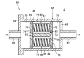
ガスコンディショナ(加湿部60)の構成について、図2~図4を参照しながら詳細に説明する。加湿部60は、ガスが流れるガス流路61が形成されるケース62と、該ガス流路61に設けられる水分付加ユニット70とを備えている。
<Detailed configuration of the gas conditioner>
The configuration of the gas conditioner (humidification section 60) will be described in detail with reference to FIGS. 2 to 4. FIG. The
ケース62は、金属材料で構成される。ケース62は、熱伝導率の高い材料であり、例えばステンレス材料で構成される。ケース62は、ケース本体63、フランジ64、及び閉塞板65を備える。ケース本体63は、両端が開口する筒状(厳密には円筒状)に形成される。フランジ64は、ケース本体63の軸方向の一端(左端)部に取り付けられ、該一端側の開口を閉塞する。閉塞板65は、ケース本体63の軸方向の他端(右端)部に取り付けられ、該他端側の開口を閉塞する。フランジ64の中央部分には、第1ガス管66が接続される。閉塞板65の中央部分には、第2ガス管67が接続される。例えば第1ガス管66は、第1流路31のガスをガス流路61に流入させるガス流入管を構成し、第2ガス管67は、ガス流路61のガスを第2流路32に流出させるガス流出管を構成する。第2ガス管67をガス流入管とし、第1ガス管66をガス流出管としてもよい。
ケース62は、空調空間Sに配置される。空調空間Sは、空気調和装置が導入される半導体製造設備に設けられる。従って、この空気調和装置により、空調空間Sの空気温度が目標温度に維持される。
The
図2に示すように、水分付加ユニット70は、ケース本体63の内部に配置される。図2及び図3に示すように、水分付加ユニット70は、第1仕切板71と、第2仕切板72と、1本の支柱73と、複数の樹脂チューブ80(樹脂部材)とを備えている。
As shown in FIG. 2 , the
第1仕切板71及び第2仕切板72は、円形板状に形成されている。第1仕切板71及び第2仕切板72の外径は、ケース本体63の内径よりも僅かに小さい。従って、第1仕切板71及び第2仕切板72は、ケース本体63に内側に嵌合される。第1仕切板71は、第1ガス管66寄りに配置され、第2仕切板72は、第2ガス管67寄りに配置される。第1仕切板71及び第2仕切板72には、複数の円形の孔74が軸方向に貫通している。
The
支柱73は、第1仕切板71と第2仕切板72の間に介設される。支柱73は、円柱状の長尺の部材である。支柱73の長手方向の一端は、第1仕切板71の軸心部に締結される。支柱73の長手方向の他端は、第2仕切板72の軸心部に締結される。
The
フランジ64と第1仕切板71との間には、第1ヘッダ空間75が形成される。閉塞板65と第2仕切板72との間には、第2ヘッダ空間76が形成される。第1仕切板71と第2仕切板72との間には、加湿流路77が形成される。加湿流路77は、ガス流路61の一部であり、且つ樹脂チューブ80を収容する収容室を構成している。
A
図3に示すように、水分付加ユニット70は、3つの樹脂チューブ80を備えている。樹脂チューブ80の数量は単なる一例である。樹脂チューブ80は、1つ又は2つであってもよいし、4つ以上であってもよい。
As shown in FIG. 3 , the
本実施形態の樹脂チューブ80は、水分を透過する透水性を有する樹脂材料で構成される。例えば樹脂チューブ80は、PTFE、PFA、ETFE、FEPなどのフッ素系の樹脂材料で構成される。樹脂チューブ80は、水が封入される密閉状の中空体で構成される。
The
本実施形態の樹脂チューブ80は、螺旋状に形成されている。より詳細には、各樹脂チューブ80は、螺旋状の周壁部81と、該周壁部81の両端を閉塞する一対の閉塞部82,82とを備えている。周壁部81は、第1ガス管66及び第2ガス管67の延在方向に沿った軸心を中心として旋回する螺旋状に形成される。換言すると、周壁部81は、ケース62の内周面に沿うように旋回する螺旋状に形成される。一対の閉塞部82,82は、周壁部81の長手方向の両端の開口をそれぞれ閉塞している。一対の閉塞部82,82は、周壁部81の両端の開口縁部を熱によって溶融させた後、閉塞させることで成形される。つまり、閉塞部82は、周壁部81の両端の開口縁部を融着させた融着部を構成している。これにより、水分が封入された樹脂チューブ80を容易に製造できる。
The
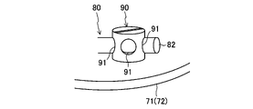
図4に模式的に示すように、第1仕切板71及び第2仕切板72には、複数の樹脂チューブ80が着脱可能となっている。つまり、第1仕切板71及び第2仕切板72は、複数の樹脂チューブ80を着脱可能に支持する支持部を構成している。
As schematically shown in FIG. 4, a plurality of
具体的に、第1仕切板71及び第2仕切板72には、樹脂チューブ80を固定するための固定具90が設けられる。固定具90は、径方向に延びる複数の貫通穴91が形成された円柱状に形成される。固定具90の基端側には雄ねじ部(図示省略)が形成される。固定具90の雄ねじ部が、第1仕切板71や第2仕切板72に形成したねじ穴(図示省略)に締結されることで、固定具90が各仕切板71,72に固定される。
Specifically,
樹脂チューブ80の端部の外径は、固定具90の貫通穴91の口径よりも僅かに小さい。樹脂チューブ80の端部を固定具90の貫通穴91に差し込むことで、樹脂チューブ80の端部が固定具90に固定される。このようにして樹脂チューブ80の両端をそれぞれ固定具90に固定することで、樹脂チューブ80が各仕切板71,72の間に保持される。一方、樹脂チューブ80の両端を貫通穴91からそれぞれ引き抜くことで、樹脂チューブ80が各仕切板71,72から取り外される。
The outer diameter of the end of the
-運転動作-
オゾン発生装置10においてオゾンを発生するための運転動作(オゾン発生方法)について詳細に説明する。
-Driving behavior-
An operation operation (ozone generation method) for generating ozone in the
オゾン発生装置10が運転されると、酸素ガス源5の酸素ガスは、除湿部27を通過する。除湿部27では、酸素ガス源5からの酸素ガス中の水分を10ppb以下にまで除去する除湿工程が行われる。このため、酸素ガス源5の酸素ガス中に水分がある程度の水分が含まれていたり、この酸素ガスの水分量が変化したりしても、除去工程を得た酸素ガス中の水分量は実質的にゼロとなる。
When the
除湿工程により、水分量が10ppb以下となった酸素ガスは、第1流路31より、加湿部60に流入する。加湿部60では、酸素ガスに水分を付与する加湿工程が行われる(詳細は後述する)。ここで、加湿部60には、除湿部27によって水分が実質的にゼロとなった酸素ガスが供給される。このため、例えば酸素ガス源5から供給される酸素ガスの水分量が僅かに変化したとしても、加湿部60に供給される酸素ガス中の水分量はほぼ変化しない(ゼロのまま)である。このため、加湿部60の加湿能力に影響を与える外的要因が減るため、第1流路31から第2流路32へ供給される酸素ガス中の水分量の変化を抑制できる。
The oxygen gas whose water content is reduced to 10 ppb or less by the dehumidifying process flows into the
〈加湿工程の詳細〉
上述した加湿工程では、酸素ガスが第1ガス管66を流れた後、第1ヘッダ空間75に流入する。第1ヘッダ空間75の酸素ガスは、第1仕切板71の複数の孔74に分流した後、加湿流路77に流入する。
<Details of humidification process>
In the humidification process described above, the oxygen gas flows into the
加湿流路77では、酸素ガスが複数の樹脂チューブ80の周囲を流れる。この際、樹脂チューブ80内の水は樹脂チューブ80を透過し、酸素ガス中へ移動する。これにより、酸素ガス中に極微量の水分が付与される。水分が付与された酸素ガスは、第2仕切板72の複数の孔74に分流した後、第2ヘッダ空間76で合流する。第2ヘッダ空間76の酸素ガスは、第2ガス管67を流れた後、第2流路32へ送られる。
Oxygen gas flows around the plurality of
このような加湿工程では、ケース62の周囲の空調空間Sの空気の温度が空気調和装置によって調節される。ケース62は、熱伝導率の高いステンレス材料で構成されるため、ガス流路61を流れるガス温度は、空調空間Sの空気の温度に近づく。樹脂チューブ80は、ガス流路61に配置されるため、樹脂チューブ80内の水温は、ガス流路61を流れるガス温度に近づく。よって、樹脂チューブ80内の水温が、空調空間Sの空気の温度に近づくため、この水温を空気調和装置によって管理できる。従って、樹脂チューブ80内の水温が大きく変動することがないため、このような水温の変化に起因してガス中に放出される水分量が変化してしまうことを抑制できる。
In such a humidification process, the air conditioner adjusts the temperature of the air in the air-conditioned space S around the
加湿工程では、樹脂チューブ80内の水がガス中に付与される際、酸素ガスが樹脂チューブ80内に透過する。このため、樹脂チューブ80から水分が放出されても、樹脂チューブ80の内圧が大きく低下することがない。従って、樹脂チューブ80の内圧の変化に起因してガス中に放出される水分量が変化してしまうことを抑制できる。
In the humidification process, oxygen gas permeates into the
加湿工程では、樹脂チューブ80から極めて微量の水分がガス中に付与される。このため、樹脂チューブ80内の水の減少速度は極めて遅く、樹脂チューブ80内の水がなくなってしまうまでの期間は十分に長い。従って、樹脂チューブ80を頻繁に交換する必要はない。
In the humidification process, an extremely small amount of water is added to the gas from the
〈水分量の調整〉
本実施形態の加湿部60では、樹脂チューブ80の数量を変更することで、ガス中に放出される水分量を調整できる。具体的には、水分付加ユニット70に取り付ける樹脂チューブ80の数を増やすことで、ガス中に付与される水分量も増大する。例えば処理するガス流量が2倍になったり、目標の水分濃度が2倍になったりした場合であれば、樹脂チューブ80の数を2倍とする。これにより、単純に樹脂チューブ80の数を変更するだけで、ガス流量や目標の水分濃度に応じた量の水分をガス中に付与できる。
<Adjustment of water content>
In the
水分量を調節する手段として、樹脂チューブ80の数量以外の要因を変更させることもできる。この要因としては、例えば樹脂チューブ80の厚さ、長さ、大きさ、形状、材質、透水性能などが挙げられる。
Factors other than the number of
-実施形態の効果-
上記実施形態の樹脂チューブ80は、水が封入される密閉状の中空体で構成される。このため、従来例のように、水を搬送するポンプや、搬送する水の温度を調節するチラーユニットなどが不要となる。この結果、加湿部60の構成の簡素化を図りつつ、ガス中に付与する水分量を安定して調整できる。
- Effects of the embodiment -
The
第1仕切板71及び第2仕切板72は、複数の樹脂チューブ80を着脱可能に支持する。このため、加湿部60では、樹脂チューブ80の本数を簡単に変更でき、放出される水分量を簡単に調整できる。また、樹脂チューブ80の交換も簡単である。
The
樹脂チューブ80の両端は、樹脂を融着することにより閉塞部82,82が構成されている。従って、水が封入された樹脂チューブ80を簡単に製造できる。
At both ends of the
樹脂チューブ80は、螺旋状に形成されるため、樹脂チューブ80の容積や表面積を拡大できる。樹脂チューブ80の容積が大きくなると、樹脂チューブ80内の水がなくなるまでの期間を長期化でき、樹脂チューブ80の交換頻度を減らせる。樹脂チューブ80の
表面積が大きくなると、ガス中に付与できる水分量を増大できる。従って、樹脂チューブ80、ひいてはケース62の小型化を図ることができる。
Since the
ケース62は、金属材料で構成されるとともに空調空間Sに配置される。このため、樹脂チューブ80内の水温は、空調空間Sの温度が支配的となるので、水温管理を確実に行うことができる。
The
《実施形態の変形例》
図5に示すように、ケース62の周囲(一部又は全部)を断熱材95で覆うようにしてもよい。このようにすると、ガス流路61のガス温度が、ケース62の周囲の温度の影響により変化することを抑制できる。これにより、樹脂チューブ80の水温は、ガス流路61のガス温度が支配的となる。従って、樹脂チューブ80内の水温を、ガス流路61を流れるガス温度によって一定に管理できる。
<<Modified example of embodiment>>
As shown in FIG. 5 , the periphery (partially or entirely) of the
《その他の実施形態》
上記実施形態では、樹脂部材80が螺旋状の樹脂チューブで構成されている。しかし、樹脂部材80は、水が封入される密閉状の中空体であれば、如何なる構造であってもよい。例えば樹脂部材80は、環状であってもよい。この場合、大径の環状の樹脂部材80の内側に、小径の環状の樹脂部材80を配置することもできる。また、樹脂部材80は、棒状、平板状、円弧状、直方体状などであってもよい。
<<Other embodiments>>
In the above-described embodiment, the
上記実施形態のガスコンディショナ60は、対象ガスを酸素ガスとしている。しかし、対象ガスは、これに限られず、例えば窒素ガス、二酸化炭素ガス、空気などの他のガスであってもよい。また、ガスコンディショナ60がガス中に付与する水は、純水でなくてもよく、他の成分を含んだ水(例えば真水や水道水)であってもよい。
The
上記実施形態の加湿部60は、装置本体20内に設けられているが、加湿部60を装置本体20の外部に設けてもよい。
The
以上説明したように、本発明は、ガスコンディショナに関し有用である。 INDUSTRIAL APPLICABILITY As described above, the present invention is useful for gas conditioners.
60 加湿部(ガスコンディショナ)
61 ガス流路
62 ケース
71 第1仕切板(支持部)
72 第2仕切板(支持部)
80 樹脂チューブ(樹脂部材)
81 周壁部
82 閉塞部(融着部)
S 空調空間
60 Humidification part (gas conditioner)
61
72 second partition plate (supporting part)
80 resin tube (resin member)
81
S air-conditioned space
Claims (5)
前記ガスが流通するガス流路を形成するケースと、
前記ガス流路に配置されるとともに透水性を有する樹脂部材とを備え、
前記樹脂部材は、水が封入される密閉状の中空体で構成されることを特徴とするガスコンディショナ。 A gas conditioner that adds moisture to gas,
a case forming a gas flow path through which the gas flows;
a water-permeable resin member disposed in the gas flow path,
The gas conditioner according to claim 1, wherein the resin member is a closed hollow body in which water is enclosed.
複数の前記樹脂部材を着脱可能に支持する支持部を備えていることを特徴とするガスコンディショナ。 In claim 1,
A gas conditioner, comprising: a support portion that detachably supports the plurality of resin members.
前記樹脂部材は、筒状の周壁部と、該周壁部の両端をそれぞれ閉塞する閉塞部とを有し、
前記閉塞部は、樹脂材料の融着部によって構成されることを特徴とするガスコンディショナ。 In claim 1 or 2,
The resin member has a cylindrical peripheral wall portion and closing portions that respectively close both ends of the peripheral wall portion,
The gas conditioner according to claim 1, wherein the closing portion is composed of a fused portion of a resin material.
前記樹脂部材は、螺旋状に形成されていることを特徴とするガスコンディショナ。 In any one of claims 1 to 3,
The gas conditioner, wherein the resin member is spirally formed.
前記ケースは、金属材料で構成されるとともに、空気の温度が調節される空調空間に配置されることを特徴とするガスコンディショナ。 In any one of claims 1 to 4,
A gas conditioner according to claim 1, wherein the case is made of a metal material and arranged in an air-conditioned space where the temperature of the air is adjusted.
Priority Applications (7)
| Application Number | Priority Date | Filing Date | Title |
|---|---|---|---|
| JP2018176536A JP7133415B2 (en) | 2018-09-20 | 2018-09-20 | gas conditioner |
| PCT/JP2019/025235 WO2020059238A1 (en) | 2018-09-20 | 2019-06-25 | Gas conditioner |
| US17/277,136 US11649972B2 (en) | 2018-09-20 | 2019-06-25 | Gas conditioner |
| EP19862416.5A EP3848643A4 (en) | 2018-09-20 | 2019-06-25 | Gas conditioner |
| KR1020217008189A KR102569436B1 (en) | 2018-09-20 | 2019-06-25 | ozone generator |
| CN201980061449.XA CN112714845A (en) | 2018-09-20 | 2019-06-25 | Gas regulator |
| TW108132352A TWI798486B (en) | 2018-09-20 | 2019-09-09 | air conditioner |
Applications Claiming Priority (1)
| Application Number | Priority Date | Filing Date | Title |
|---|---|---|---|
| JP2018176536A JP7133415B2 (en) | 2018-09-20 | 2018-09-20 | gas conditioner |
Publications (2)
| Publication Number | Publication Date |
|---|---|
| JP2020044514A JP2020044514A (en) | 2020-03-26 |
| JP7133415B2 true JP7133415B2 (en) | 2022-09-08 |
Family
ID=69886897
Family Applications (1)
| Application Number | Title | Priority Date | Filing Date |
|---|---|---|---|
| JP2018176536A Active JP7133415B2 (en) | 2018-09-20 | 2018-09-20 | gas conditioner |
Country Status (7)
| Country | Link |
|---|---|
| US (1) | US11649972B2 (en) |
| EP (1) | EP3848643A4 (en) |
| JP (1) | JP7133415B2 (en) |
| KR (1) | KR102569436B1 (en) |
| CN (1) | CN112714845A (en) |
| TW (1) | TWI798486B (en) |
| WO (1) | WO2020059238A1 (en) |
Citations (3)
| Publication number | Priority date | Publication date | Assignee | Title |
|---|---|---|---|---|
| JP2004217512A (en) | 2002-12-27 | 2004-08-05 | Sumitomo Precision Prod Co Ltd | Method for generating ozone |
| JP2005337640A (en) | 2004-05-28 | 2005-12-08 | Taiyo Nippon Sanso Corp | Gas humidifier |
| CN106129437A (en) | 2016-06-22 | 2016-11-16 | 江苏绿遥燃料电池系统制造有限公司 | A kind of circular smart fuel cell humidifier and air-humidification method thereof |
Family Cites Families (16)
| Publication number | Priority date | Publication date | Assignee | Title |
|---|---|---|---|---|
| AU581986B2 (en) * | 1985-05-22 | 1989-03-09 | Fisher & Paykel Healthcare Limited | Improvements in or relating to methods of and/or apparatus for humidifying gases |
| CA2163955A1 (en) * | 1995-03-09 | 1996-09-10 | Nicholas F. Didomenico | Humidification device |
| EP1290930B1 (en) | 1998-02-05 | 2005-09-14 | E.I. Du Pont De Nemours And Company | Process for germinating plant seeds and growing a seedling |
| CN100579585C (en) * | 2000-05-18 | 2010-01-13 | 夏普公司 | Sterilization method, ion generating element, ion generating device, and air conditioning device |
| JP3547121B2 (en) | 2000-05-31 | 2004-07-28 | 大陽東洋酸素株式会社 | Medical oxygen concentrator |
| JP4166928B2 (en) * | 2000-07-10 | 2008-10-15 | 住友精密工業株式会社 | Ozone generation method |
| US20050084428A1 (en) * | 2001-12-27 | 2005-04-21 | Shigekazu Tokutake | Method of generation ozone, ozone generator, feed gas for ozone generation, and humidifier |
| JP4563118B2 (en) * | 2004-09-10 | 2010-10-13 | 三菱重工業株式会社 | humidifier |
| JP2007046801A (en) | 2005-08-05 | 2007-02-22 | Nissan Motor Co Ltd | Humidifier |
| JP5074743B2 (en) * | 2006-11-13 | 2012-11-14 | トヨタ自動車株式会社 | Hollow fiber membrane module, fuel cell system |
| JP6052661B2 (en) * | 2012-08-08 | 2016-12-27 | 国立研究開発法人産業技術総合研究所 | Trace moisture generator |
| CN203349393U (en) * | 2013-05-30 | 2013-12-18 | 东莞市晋彩实业有限公司 | A composite multifunctional air-activated dust-cleaning and sterilizing device |
| WO2015093079A1 (en) | 2013-12-19 | 2015-06-25 | 三菱電機株式会社 | Humidifier |
| JP2017506736A (en) * | 2014-02-16 | 2017-03-09 | ビー パワー テク,インコーポレイテッド | Heat / mass transfer device and system including the same |
| CN207435174U (en) * | 2017-10-19 | 2018-06-01 | 合肥康家净电器有限公司 | It is a kind of that there is the water purifier of air wetting |
| CN108224658B (en) * | 2017-12-20 | 2019-10-01 | 上海依瓦达环境技术有限公司 | New-air purifying system equipped with constant humidity mechanism |
-
2018
- 2018-09-20 JP JP2018176536A patent/JP7133415B2/en active Active
-
2019
- 2019-06-25 EP EP19862416.5A patent/EP3848643A4/en not_active Ceased
- 2019-06-25 KR KR1020217008189A patent/KR102569436B1/en active Active
- 2019-06-25 CN CN201980061449.XA patent/CN112714845A/en active Pending
- 2019-06-25 WO PCT/JP2019/025235 patent/WO2020059238A1/en unknown
- 2019-06-25 US US17/277,136 patent/US11649972B2/en active Active
- 2019-09-09 TW TW108132352A patent/TWI798486B/en active
Patent Citations (3)
| Publication number | Priority date | Publication date | Assignee | Title |
|---|---|---|---|---|
| JP2004217512A (en) | 2002-12-27 | 2004-08-05 | Sumitomo Precision Prod Co Ltd | Method for generating ozone |
| JP2005337640A (en) | 2004-05-28 | 2005-12-08 | Taiyo Nippon Sanso Corp | Gas humidifier |
| CN106129437A (en) | 2016-06-22 | 2016-11-16 | 江苏绿遥燃料电池系统制造有限公司 | A kind of circular smart fuel cell humidifier and air-humidification method thereof |
Also Published As
| Publication number | Publication date |
|---|---|
| EP3848643A1 (en) | 2021-07-14 |
| TWI798486B (en) | 2023-04-11 |
| JP2020044514A (en) | 2020-03-26 |
| TW202012304A (en) | 2020-04-01 |
| KR102569436B1 (en) | 2023-08-22 |
| US20220113041A1 (en) | 2022-04-14 |
| WO2020059238A1 (en) | 2020-03-26 |
| CN112714845A (en) | 2021-04-27 |
| US11649972B2 (en) | 2023-05-16 |
| EP3848643A4 (en) | 2021-11-17 |
| KR20210046726A (en) | 2021-04-28 |
Similar Documents
| Publication | Publication Date | Title |
|---|---|---|
| JP6070794B1 (en) | Ozone generator | |
| WO2000074122A1 (en) | Ozone treatment device of semiconductor process system | |
| US20110076190A1 (en) | Heat pump type hot-water supply device and hot water sterilization method | |
| JP7133415B2 (en) | gas conditioner | |
| JP7008125B2 (en) | Ozone generator and ozone generation method | |
| JP3708917B2 (en) | Gas ionization separation and purification equipment | |
| JP5953138B2 (en) | Wet gas generation method and humidity controller for small flow rate | |
| JP4987669B2 (en) | Carbon dioxide absorber | |
| JP6694595B2 (en) | Ozone generator | |
| JP6632463B2 (en) | Ozone gas concentration method and ozone gas concentration device | |
| WO2011152513A1 (en) | Electrostatic atomization device | |
| CN203474455U (en) | Ozone generator | |
| JP2006150268A (en) | Aeration method | |
| CN105060254B (en) | Ozone generator for tap water purification or sewage treatment | |
| JP7515745B1 (en) | Ozone supplying device and ozone supplying method | |
| JP3090888U (en) | Energy converter | |
| JP2004077216A (en) | Nitrogen oxide measuring apparatus, and method for checking conversion efficiency in converter used for measuring nitrogen oxide | |
| JP2008226805A (en) | Exhaust gas treatment equipment of fuel cell | |
| JP3311382B2 (en) | Pipe type ozone generator | |
| JP2000178010A (en) | Ozone water generating device | |
| JPH09124303A (en) | Concentration-variable ozone gas generating system | |
| JP2024040884A (en) | Fluid reforming device | |
| JP2006273589A (en) | Method and equipment for adsorbing low-concentration ozone gas | |
| JP2024030276A (en) | ozone water generator | |
| JP2016201316A (en) | Vacuum system |
Legal Events
| Date | Code | Title | Description |
|---|---|---|---|
| A621 | Written request for application examination |
Free format text: JAPANESE INTERMEDIATE CODE: A621 Effective date: 20210818 |
|
| TRDD | Decision of grant or rejection written | ||
| A01 | Written decision to grant a patent or to grant a registration (utility model) |
Free format text: JAPANESE INTERMEDIATE CODE: A01 Effective date: 20220823 |
|
| A61 | First payment of annual fees (during grant procedure) |
Free format text: JAPANESE INTERMEDIATE CODE: A61 Effective date: 20220829 |
|
| R150 | Certificate of patent or registration of utility model |
Ref document number: 7133415 Country of ref document: JP Free format text: JAPANESE INTERMEDIATE CODE: R150 |