JP7122914B2 - Optical communication system, optical communication device, control method, and control program - Google Patents
Optical communication system, optical communication device, control method, and control program Download PDFInfo
- Publication number
- JP7122914B2 JP7122914B2 JP2018170141A JP2018170141A JP7122914B2 JP 7122914 B2 JP7122914 B2 JP 7122914B2 JP 2018170141 A JP2018170141 A JP 2018170141A JP 2018170141 A JP2018170141 A JP 2018170141A JP 7122914 B2 JP7122914 B2 JP 7122914B2
- Authority
- JP
- Japan
- Prior art keywords
- station device
- slave station
- time
- optical
- relay processing
- Prior art date
- Legal status (The legal status is an assumption and is not a legal conclusion. Google has not performed a legal analysis and makes no representation as to the accuracy of the status listed.)
- Active
Links
- 230000003287 optical effect Effects 0.000 title claims description 178
- 238000004891 communication Methods 0.000 title claims description 118
- 238000000034 method Methods 0.000 title claims description 48
- 238000012545 processing Methods 0.000 claims description 191
- 230000005540 biological transmission Effects 0.000 claims description 105
- 238000004364 calculation method Methods 0.000 claims description 7
- 239000000284 extract Substances 0.000 claims description 5
- 230000001934 delay Effects 0.000 claims description 3
- 238000011144 upstream manufacturing Methods 0.000 description 93
- 238000010586 diagram Methods 0.000 description 36
- 238000012937 correction Methods 0.000 description 10
- 238000006243 chemical reaction Methods 0.000 description 9
- 238000000605 extraction Methods 0.000 description 9
- 230000008054 signal transmission Effects 0.000 description 7
- 239000013307 optical fiber Substances 0.000 description 3
- 230000003044 adaptive effect Effects 0.000 description 2
- 230000000052 comparative effect Effects 0.000 description 2
- 239000006185 dispersion Substances 0.000 description 2
- 230000006866 deterioration Effects 0.000 description 1
- 230000000694 effects Effects 0.000 description 1
- 238000012986 modification Methods 0.000 description 1
- 230000004048 modification Effects 0.000 description 1
- 230000010363 phase shift Effects 0.000 description 1
- 230000010287 polarization Effects 0.000 description 1
- 238000007781 pre-processing Methods 0.000 description 1
- 239000007787 solid Substances 0.000 description 1
Images


Landscapes
- Small-Scale Networks (AREA)
Description
本発明は、光通信システム、光通信装置、制御方法、及び制御プログラムに関する。 The present invention relates to an optical communication system, an optical communication device, a control method, and a control program.
光通信システムであるPON(Passive Optical Network)システムが、知られている。PONシステムは、通信事業者局舎に設置される光通信装置(親局装置とも言う)と、加入者側(子局側とも言う)の複数の光通信装置(子局装置とも言う)とを含む。親局装置は、OLT(Optical Line Termination)と言う。子局装置は、ONU(Optical Network Unit)と言う。 A PON (Passive Optical Network) system, which is an optical communication system, is known. A PON system consists of an optical communication device (also referred to as a master station device) installed in a communication carrier office building and a plurality of optical communication devices (also referred to as slave station devices) on the subscriber side (also referred to as a slave station side). include. The parent station device is called an OLT (Optical Line Termination). A slave station device is called an ONU (Optical Network Unit).
PONシステムには、上り信号の時分割多重に基づく制御が行われる。なお、上り信号とは、ONUがOLTに送信する光信号である。当該制御は、IEEE802.3で標準化されている(非特許文献1を参照)。 The PON system is controlled based on time-division multiplexing of upstream signals. Note that the upstream signal is an optical signal transmitted from the ONU to the OLT. The control is standardized by IEEE802.3 (see Non-Patent Document 1).
PONシステムでは、伝送距離を伸ばすために、中継器が含まれる。ここで、中継器を含む通信システムが提案されている(特許文献1,2を参照)。中継器は、中継処理を行う。例えば、中継処理とは、誤り訂正処理又は波形歪みを補償する等化処理である。例えば、中継器は、等化処理として、適応等化アルゴリズムを用いて、偏波モード分散(PMD:Polarization Mode Dispersion)及び波長分散(CD:Chromatic Dispersion)等の影響による波形歪みを補償する。また、例えば、適応等化アルゴリズムは、QPSK(Quadrature Phase Shift Keying)で変調された位相変調信号をデジタルコヒーレント受信するときに用いられるCMA(Constant Modulus Algorithm)である。
Repeaters are included in PON systems to extend the transmission distance. Here, communication systems including repeaters have been proposed (see
ここで、等化処理を行うOLTが提案されている(特許文献3を参照)。 Here, an OLT that performs equalization processing has been proposed (see Patent Document 3).
ところで、複数の通信方式で通信が行われるPONシステムがある。例えば、複数の通信方式とは、複数の通信速度又は複数の変調方式である。当該PONシステムには、OLTと複数のONUとの間に中継器が配置される。複数の通信方式で通信されるため、中継器は、通信方式毎に中継処理を行う。中継処理の実行時間は、通信方式毎に異なる。当該PONシステムでは、時分割多重に基づいて上り信号が制御される。例えば、当該PONシステムに含まれるOLTは、ある上り信号の受信タイミングで当該上り信号と他の上り信号とが衝突しないように、上り信号の送信開始時刻を複数のONUに設定する。しかし、OLTは、複数のONUと中継器との間で上り信号が衝突しないように送信開始時刻を算出していない場合がある。そのため、複数のONUと中継器との間で上り信号の衝突が発生する可能性がある。すなわち、通信方式毎に中継処理の実行時間が異なることをOLTが考慮しないで送信開始時刻を算出するため、ONUと中継器との間で上り信号の衝突が発生する可能性がある。 By the way, there is a PON system in which communication is performed by a plurality of communication methods. For example, multiple communication schemes are multiple communication speeds or multiple modulation schemes. In the PON system, repeaters are arranged between the OLT and a plurality of ONUs. Since communication is performed by a plurality of communication methods, the repeater performs relay processing for each communication method. The execution time of relay processing differs for each communication method. In the PON system, upstream signals are controlled based on time division multiplexing. For example, the OLT included in the PON system sets uplink signal transmission start times to a plurality of ONUs so that the uplink signal does not collide with another uplink signal at the reception timing of the uplink signal. However, there are cases where the OLT does not calculate the transmission start time so that upstream signals do not collide between multiple ONUs and repeaters. Therefore, upstream signal collision may occur between a plurality of ONUs and repeaters. That is, since the OLT calculates the transmission start time without considering that the execution time of the relay process differs depending on the communication system, there is a possibility that upstream signals collide between the ONU and the relay.
本発明の目的は、上り信号の衝突を回避することである。 An object of the present invention is to avoid upstream signal collision.
本発明の一態様に係る光通信システムが提供される。光通信システムは、第1の子局装置、第2の子局装置、中継器、及び親局装置を含む。前記第1の子局装置は、第1の通信方式で通信する。前記第2の子局装置は、第2の通信方式で通信する。前記中継器は、前記第1の子局装置及び前記第2の子局装置と、前記親局装置との間に存在し、前記第1の子局装置が送信した光信号を受信した場合、受信した光信号に対して処理を行い、処理を終了した後の光信号を前記親局装置に送信し、前記第2の子局装置が送信した光信号を受信した場合、受信した光信号に対して処理を行い、処理を終了した後の光信号を前記親局装置に送信する。前記親局装置は、前記第1の子局装置が送信した光信号に対して前記中継器が処理を実行する時間である第1の中継処理時間と、前記第2の子局装置が送信した光信号に対して前記中継器が処理を実行する時間である第2の中継処理時間とに基づいて算出されたガードタイムに応じて、前記第1の子局装置に光信号を送信させた後、次に、前記第2の子局装置に光信号の送信を開始させる時刻である送信開始時刻を算出する。 An optical communication system is provided according to one aspect of the present invention. An optical communication system includes a first slave station device, a second slave station device, a repeater, and a master station device. The first slave station device communicates in a first communication scheme. The second slave station device communicates by a second communication method. The repeater is present between the first slave station device and the second slave station device and the master station device, and when receiving an optical signal transmitted by the first slave station device, The received optical signal is processed, the processed optical signal is transmitted to the master station device, and when the optical signal transmitted by the second slave station device is received, the received optical signal is: Then, the optical signal after the processing is completed is transmitted to the master station apparatus. The master station device sets a first relay processing time, which is a time during which the repeater executes processing on the optical signal transmitted by the first slave station device, and After causing the first slave station device to transmit an optical signal in accordance with a guard time calculated based on a second relay processing time, which is a time during which the repeater performs processing on the optical signal Next, the transmission start time is calculated, which is the time at which the second slave station device starts transmission of the optical signal.
本発明によれば、上り信号の衝突を回避できる。 According to the present invention, collision of upstream signals can be avoided.
以下、図面を参照しながら実施の形態を説明する。以下の実施の形態は、例にすぎず、本発明の範囲内で種々の変更が可能である。 Embodiments will be described below with reference to the drawings. The following embodiments are merely examples, and various modifications are possible within the scope of the present invention.
実施の形態1.
図1は、実施の形態1の光通信システムを示す図である。光通信システムは、OLT100、ONU201~204、及び中継器300を含む。図1は、ONUの数が4つの場合を例示している。しかし、ONUの数は、4つに限らない。
OLT100と中継器300との間は、光ファイバで接続されている。ONU201~204と中継器300は、光カプラ400を介して接続する。中継器300と光カプラ400との間は、光ファイバで接続されている。ONU201~204と光カプラ400との間は、光ファイバで接続されている。
FIG. 1 is a diagram showing an optical communication system according to
An optical fiber connects between the OLT 100 and the
OLT100は、制御方法を実行する装置である。OLT100は、端末装置500と接続する。OLT100は、上位ネットワーク(図示を省略)に接続する。OLT100は、上位ネットワークから取得した情報(電気信号)を光信号に変換して、当該光信号をONUに送信することができる。OLT100がONUに送信する光信号を下り信号と表現する。また、ONUが送信する光信号を上り信号と表現する。OLT100は、上り信号(すなわち、光信号)を電気信号に変換し、当該電気信号を上位ネットワークに送信することができる。
The OLT 100 is a device that executes control methods. The OLT 100 connects with the
ONU201,202は、第1の通信方式で通信する光通信装置である。詳細には、ONU201,202は、10Gbpsの通信速度で通信する光通信装置である。10Gbpsの通信速度は、第1の通信速度とも言う。
ONU203,204は、第2の通信方式で通信する光通信装置である。詳細には、ONU203,204は、1Gbpsの通信速度で通信する光通信装置である。例えば、1Gbpsの通信速度は、第2の通信速度とも言う。また、10Gbpsの通信速度が第2の通信速度と考えた場合、1Gbpsの通信速度は、第1の通信速度と考えてもよい。
The ONUs 201 and 202 are optical communication devices that communicate using the first communication method. Specifically, the ONUs 201 and 202 are optical communication devices that communicate at a communication speed of 10 Gbps. The communication speed of 10 Gbps is also called a first communication speed.
このように、光通信システムは、複数の異なる通信速度で通信するシステムである。そのため、例えば、光通信システムは、10G-EPON(10Gigabit Ethernet Passive Optical Network)システムと考えてもよい。 Thus, an optical communication system is a system that communicates at multiple different communication speeds. Therefore, for example, the optical communication system may be considered as a 10G-EPON (10 Gigabit Ethernet Passive Optical Network) system.
ONU201~204のそれぞれは、各ユーザネットワーク(図示を省略)に接続する。例えば、ONU201は、下り信号(すなわち、光信号)を電気信号に変換し、当該電気信号をユーザネットワークに送信することができる。また、ONU201は、ユーザネットワークから取得した電気信号を光信号に変換し、当該光信号(すなわち、上り信号)をOLT100に送信することができる。
中継器300は、OLT100とONU201~204との間の伝送距離を長くするために、介在している。すなわち、中継器300は、OLT100とONU201~204との間に存在する。中継器300は、OLT100とONU201~204との間で光信号を中継する。
Each of the ONUs 201-204 is connected to each user network (not shown). For example,
中継器300は、上り信号(すなわち、光信号)を電気信号に変換する。中継器300は、電気信号に対して中継処理を実行する。例えば、中継処理は、誤り訂正処理である。中継器300は、中継処理が終わった後の電気信号を光信号に変換する。中継器300は、当該光信号をOLT100に送信する。また、中継器300は、中継処理で波形歪みを補償する等化処理を実行してもよい。
The
光カプラ400は、下り信号をONU201~204に分配することができる。また、光カプラ400は、複数の上り信号を集約することができる。
端末装置500は、管理者が使用する装置である。端末装置500は、管理者の操作により、OLT100に様々な設定を行う。
The
A
ここで、ONU201又はONU202は、第1の子局装置とも言う。ONU201又はONU202が第1の子局装置の場合、ONU201及びONU202は、第1の子局装置群とも言う。また、ONU201又はONU202は、第2の子局装置と考えてもよい。ONU201又はONU202が第2の子局装置の場合、ONU201及びONU202は、第2の子局装置群とも言う。
Here, the
また、ONU203又はONU204は、第2の子局装置とも言う。ONU203又はONU204が第2の子局装置の場合、ONU203及びONU204は、第2の子局装置群とも言う。また、ONU203又はONU204は、第1の子局装置と考えてもよい。ONU203又はONU204が第1の子局装置の場合、ONU203及びONU204は、第1の子局装置群とも言う。
なお、子局装置群に含まれている複数のONUは、同じ通信方式で通信すると言える。
The
It can be said that a plurality of ONUs included in the slave station device group communicate using the same communication method.
次に、OLT100の主なハードウェア構成について説明する。
図2は、実施の形態1のOLTが有する主なハードウェア構成を示す図である。OLT100は、プロセッサ101、揮発性記憶装置102、及び不揮発性記憶装置103を有する。
Next, the main hardware configuration of the
FIG. 2 is a diagram showing the main hardware configuration of the OLT of
プロセッサ101は、OLT100全体を制御する。例えば、プロセッサ101は、CPU(Central Processing Unit)、又はFPGA(Field Programmable Gate Array)などである。プロセッサ101は、マルチプロセッサでもよい。OLT100は、処理回路によって実現されてもよく、又は、ソフトウェア、ファームウェア若しくはそれらの組み合わせによって実現されてもよい。なお、処理回路は、単一回路又は複合回路でもよい。
A
揮発性記憶装置102は、OLT100の主記憶装置である。例えば、揮発性記憶装置102は、RAM(Random Access Memory)である。不揮発性記憶装置103は、OLT100の補助記憶装置である。例えば、不揮発性記憶装置103は、HDD(Hard Disk Drive)又はSSD(Solid State Drive)である。
ONU201~204と中継器300は、OLT100と同様に、プロセッサ、揮発性記憶装置、及び不揮発性記憶装置を有する。
A
The
次に、MPCP(Multi-Point Control Protocol)プロセスについて説明する。
図3は、実施の形態1のMPCPプロセスを説明するための図である。図3は、OLT100とONU201とを用いて説明する。また、図3は、中継器300を省略している。
Next, the MPCP (Multi-Point Control Protocol) process will be described.
FIG. 3 is a diagram for explaining the MPCP process of
(ステップS101)OLT100は、論理的な接続関係を確立するために、Discovery Gateフレームを送信する。
(ステップS102)OLT100は、Discovery Gateフレームを送信する。
このように、OLT100は、定期的にDiscovery Gateフレームを送信する。
(Step S101) The
(Step S102) The
Thus, the
(ステップS103)ONU201は、Discovery Gateフレームを受信した場合、Register RequestフレームをOLT100に送信する。
(ステップS104)OLT100は、Register Requestフレームを受信する。OLT100は、Register Requestフレームを受信することで、ONU201の存在を検出する。また、OLT100は、OLT100とONU201との間のフレーム往復時間を把握する。フレーム往復時間は、RTT(Round Trip Time)とも言う。
(Step S<b>103 ) When the
(Step S104) The
OLT100は、Registerフレームを送信する。Registerフレームは、LLID(Logical Link Identifier)をONU201に割当てるためのフレームである。ONU201にLLIDを割当てることで、ONU201は、割当てられたLLIDを含むフレームを受信した場合、自分宛に送信された情報であることを検出できる。
(ステップS105)OLT100は、Normal Gateフレームを送信する。Normal Gateフレームは、上り信号の送信開始時刻を含む。送信開始時刻は、ONUに上り信号の送信を開始させる時刻である。また、送信開始時刻は、上り信号の送信の開始を許可する時刻と表現してもよい。
(ステップS106)ONU201は、Normal Gateフレームに含まれている送信開始時刻に、Register ACKフレームを送信する。
(Step S105) The
(Step S106)
(ステップS107)OLT100は、Register ACKフレームを受信する。OLT100は、Register ACKフレームを受信することで、LLIDの登録を完了する。これにより、OLT100とONU201との間で論理的な接続関係が確立する。ここで、論理的な接続関係をPONリンクとも言う。
OLT100は、Normal Gateフレームを送信する。
(Step S107) The
(ステップS108)ONU201は、自装置内に蓄積しているデータのデータ量をReportフレームに登録する。ここで、当該データ量は、送信要求データ量とも言う。ONU201は、Reportフレームを送信する。
(ステップS109)OLT100は、上り信号の送信開始時刻と帯域とをNormal Gateフレームに登録する。OLT100は、Normal Gateフレームを送信する。
(ステップS110)ONU201は、Normal Gateフレームに含まれている送信開始時刻に、データを含む上り信号を送信する。
(Step S108)
(Step S109) The
(Step S110) The
次に、中継器とOLTが有する機能について説明する。
図4は、実施の形態1の中継器の構成を示す機能ブロック図である。また、図4では、上り信号に対する中継器300の処理を説明する。
中継器300は、光/電気変換部310、中継処理部320、中継処理部330、及び電気/光変換部340を有する。
Next, functions of the repeater and the OLT will be described.
4 is a functional block diagram showing the configuration of the repeater according to the first embodiment; FIG. Also, FIG. 4 explains the processing of the
The
光/電気変換部310、中継処理部320、中継処理部330、及び電気/光変換部340の一部又は全部は、中継器300が有するプロセッサによって実現してもよい。光/電気変換部310、中継処理部320、中継処理部330、及び電気/光変換部340の一部又は全部は、中継器300が有するプロセッサが実行するプログラムのモジュールとして実現してもよい。
A part or all of the optical/
光/電気変換部310は、上り信号(すなわち、光信号)を電気信号に変換する。詳細に説明する。光/電気変換部310は、10Gbpsで通信するONU201,202が送信した上り信号を電気信号に変換する。光/電気変換部310は、変換した電気信号を中継処理部320に送信する。また、光/電気変換部310は、1Gbpsで通信するONU203,204が送信した上り信号を電気信号に変換する。光/電気変換部310は、変換した電気信号を中継処理部330に送信する。
The optical/
光/電気変換部310は、WDM(Wavelength Division Multiplexing)フィルタを用いて、ONU201,202が送信した上り信号とONU203,204が送信した上り信号と分岐してもよい。また、上り信号を分岐する方法は、これ以外の方法でもよい。
The optical/
中継処理部320は、光/電気変換部310から受信した電気信号に対して中継処理を実行する。例えば、中継処理部320は、光/電気変換部310から受信した電気信号に対して誤り訂正処理を実行する。詳細には、中継処理部320は、電気信号(すなわち、データ)に誤りがあるか否かを判定する。中継処理部320は、電気信号(すなわち、データ)に誤りがある場合、誤りを訂正する。
また、中継処理部320は、波形歪みを補償する等化処理を実行してもよい。
The
Also, the
中継処理部330は、光/電気変換部310から受信した電気信号に対して中継処理を実行する。例えば、中継処理部330は、光/電気変換部310から受信した電気信号に対して誤り訂正処理を実行する。詳細には、中継処理部330は、電気信号(すなわち、データ)に誤りがあるか否かを判定する。中継処理部330は、電気信号(すなわち、データ)に誤りがある場合、誤りを訂正する。
また、中継処理部330は、波形歪みを補償する等化処理を実行してもよい。
The
Also, the
電気/光変換部340は、中継処理部320から電気信号を受信する。電気/光変換部340は、電気信号を光信号(すなわち、上り信号)に変換する。電気/光変換部340は、上り信号をOLT100に送信する。また、電気/光変換部340は、中継処理部330から電気信号を受信する。電気/光変換部340は、電気信号を光信号(すなわち、上り信号)に変換する。電気/光変換部340は、上り信号をOLT100に送信する。
The electrical/
図5は、実施の形態1のOLTの構成を示す機能ブロック図である。OLT100は、記憶部110、光送受信部120、信号処理部130、ガードタイム算出部140、及び制御部11を有する。制御部11は、PON制御部150を含む。また、制御部11の機能は、PON制御部150の機能と同じである。そのため、制御部11の機能については、PON制御部150を用いて説明する。
5 is a functional block diagram showing the configuration of the OLT according to the first embodiment; FIG. The
記憶部110は、揮発性記憶装置102及び不揮発性記憶装置103に確保した記憶領域として実現できる。
光送受信部120、信号処理部130、ガードタイム算出部140、及びPON制御部150の一部又は全部は、プロセッサ101によって実現してもよい。光送受信部120、信号処理部130、ガードタイム算出部140、及びPON制御部150の一部又は全部は、プロセッサ101が実行するプログラムのモジュールとして実現してもよい。当該プログラムは、制御プログラムとも言う。
The
A part or all of the optical transmitter/
記憶部110は、中継処理テーブルを記憶する。中継処理テーブルは、端末装置500がOLT100に登録した情報に基づいて作成されたテーブルである。中継処理テーブルについては、後述する。
光送受信部120は、中継器300を介して、ONU201~204が送信した上り信号を受信する。光送受信部120は、上り信号を電気信号に変換する。光送受信部120は、変換した電気信号を信号処理部130に送信する。また、光送受信部120は、信号処理部130から受信した電気信号を下り信号に変換する。光送受信部120は、下り信号を送信する。
The optical transmitter/
信号処理部130は、電気信号をPON制御部150に送信するための前処理を行う。例えば、信号処理部130は、誤り訂正処理を行う。また、信号処理部130は、上位ネットワーク10を介してデータを受信する。
ガードタイム算出部140は、中継処理テーブルに登録されている情報を用いてガードタイムを算出する。ガードタイムの算出については、後述する。
The
The
PON制御部150は、IEEE802.3に規定されているMPCP機能に関する制御を行う。具体的には、PON制御部150は、PONリンクの確立、RTTの算出、及びNormal Gateフレームの生成を行う。
The
次に、中継処理テーブルについて説明する。
図6は、実施の形態1の中継処理テーブルを示す図である。中継処理テーブル111は、記憶部110に格納されている。中継処理テーブル111は、ONU ID、中継処理種別、及び中継処理時間の項目を有する。
Next, the relay processing table will be explained.
6 is a diagram showing a relay processing table according to
ONU IDの項目は、ONUのIDを示す。例えば、ONU IDの項目には、ONU1、ONU2、ONU3、及びONU4が登録される。ONU1は、ONU201のIDである。ONU2は、ONU202のIDである。ONU3は、ONU203のIDである。ONU4は、ONU204のIDである。 The ONU ID item indicates the ONU ID. For example, ONU1, ONU2, ONU3, and ONU4 are registered in the ONU ID item. ONU1 is the ID of ONU201. ONU2 is the ID of ONU202. ONU3 is the ID of ONU203. ONU4 is the ID of ONU204.
中継処理種別の項目は、処理種別を示す。例えば、中継処理種別の項目には、A1が登録される。A1は、中継処理部320が誤り訂正処理を実行することを示す。また、例えば、中継処理種別の項目には、B1が登録される。B1は、中継処理部330が誤り訂正処理を実行することを示す。
The relay processing type item indicates the processing type. For example, A1 is registered in the relay process type item. A1 indicates that the
中継処理時間の項目は、ONUが送信した光信号に対して中継器300が処理を実行する時間を示す。例えば、中継処理時間の項目には、SPAが登録される。SPAは、中継処理部320が実行する誤り訂正処理の実行時間である。また、例えば、中継処理時間の項目には、SPBが登録される。SPBは、中継処理部330が実行する誤り訂正処理の実行時間である。
The relay processing time item indicates the time for the
ここで、SPAは、第1の中継処理時間とも言う。SPBは、第2の中継処理時間とも言う。また、SPAが第2の中継処理時間と考えた場合、SPBは、第1の中継処理時間と考えてもよい。
中継処理テーブル111は、ONU ID、中継処理種別、及び中継処理時間の項目を有する。しかし、中継処理テーブル111は、中継処理種別の項目を有していなくてもよい。
Here, SPA is also referred to as first relay processing time. SPB is also called a second relay processing time. Also, when SPA is considered as the second relay processing time, SPB may be considered as the first relay processing time.
The relay processing table 111 has items of ONU ID, relay processing type, and relay processing time. However, the relay processing table 111 may not have the relay processing type item.
図7は、実施の形態1のDiscovery Gateシーケンスを示す図である。Discovery Gateシーケンスは、図3のステップS102,103に対応する。また、図7では、OLT100とONU201と中継器300とを用いて説明する。図7の横軸は、時間である。
7 is a diagram showing a Discovery Gate sequence according to
図7は、OLT100が時刻T1にDiscovery Gateフレーム21を送信したことを示している。Discovery Gateフレーム21は、時刻T1の情報を含む。ONU201は、Discovery Gateフレーム21を受信する。ONU201は、ONU201が管理している時間の時刻T2を時刻T1に設定する。これにより、時刻T2と時刻T1が同じになる。
FIG. 7 shows that the
また、Discovery Gateフレーム21には、ONU201にRegister Requestフレームを送信させる時刻T4が含まれている。時刻T4は、OLT100が管理している時間の時刻である。そして、時刻T4は、ONU201が管理している時間の時刻T3に対応する。すなわち、時刻T3と時刻T4は、同じ時刻である。
ONU201は、時刻T3にRegister Requestフレーム22を送信する。Register Requestフレーム22には、ONU201がRegister Requestフレーム22を送信した時刻T3(すなわち、時刻T4)が含まれている。
The
中継器300は、Register Requestフレーム22を受信する。なお、図1の時刻T5は、Register Requestフレーム22の受信開始時刻である。図1の時刻T6は、Register Requestフレーム22の受信終了時刻である。中継器300は、Register Requestフレーム22に対して中継処理を実行する。中継器300は、中継処理を実行終了後、Register Requestフレーム22をOLT100に送信する。
The
OLT100は、Register Requestフレーム22を時刻T7に受信する。OLT100は、式(1)を用いて、中継処理時間を含んだRTTを算出できる。
The
RTT=(T7-T1)-(T3-T2)=(T7-T1)-(T4-T1)=T7-T4・・・(1) RTT=(T7-T1)-(T3-T2)=(T7-T1)-(T4-T1)=T7-T4 (1)
このように、OLT100は、中継処理時間を含んだRTTを算出できる。
Thus, the
図8は、実施の形態1のNormal Gateシーケンスの比較例を示す図である。例えば、Normal Gateシーケンスは、図3のステップS109,110に対応する。
図8の光通信システムは、OLT900、ONU901,902、及び中継器903を含む。ONU901は、10Gbpsの通信速度で通信する光通信装置である。ONU902は、1Gbpsの通信速度で通信する光通信装置である。
FIG. 8 is a diagram showing a comparative example of the Normal Gate sequence of
The optical communication system of FIG. 8 includes
中継器903は、ONU901が送信した上り信号に対して中継処理を実行する。中継処理時間は、SPAである。SPAは、ONU201,202が送信した上り信号に対して中継器300が実行する中継処理の実行時間と同じである。また、中継器903は、ONU902が送信した上り信号に対して中継処理を実行する。中継処理時間は、SPBである。SPBは、ONU203,204が送信した上り信号に対して中継器300が実行する中継処理の実行時間と同じである。
The
OLT900は、Normal Gateフレームを送信する。Normal Gateフレームは、ONU901に上り信号の送信を許可する送信開始時刻T11とONU902に上り信号の送信を許可する送信開始時刻T12を含む。
ONU901は、送信開始時刻T11に上り信号を送信する。ONU902は、送信開始時刻T12に上り信号を送信する。
ここで、OLT900は、ONU901が送信した上り信号の受信タイミングで、ONU901が送信した上り信号とONU902が送信した上り信号とが衝突しないように、送信開始時刻T11,T12をONU901,902に設定する。しかし、OLT900は、ONU901,902と中継器903との間で上り信号が衝突しないように送信開始時刻を算出していない場合がある。図8は、ONU901が送信した上り信号を中継器903が受信しているときにONU902が送信した上り信号が中継器903に到達していることを示している。すなわち、図8は、ONU901が送信した上り信号とONU902が送信した上り信号とが衝突していることを示している。
Here, the
そこで、OLT100は、ONUと中継器との間で上り信号が衝突しないようにする。詳細に説明する。OLT100は、上り信号の衝突が発生しないように、通信方式が変わる度にガードタイムを一定値以上空ける。次に、ガードタイムの算出方法について、図8を用いて説明する。なお、図8のガードタイムは、Tlongである。
Therefore, the
ONU901が送信した上り信号を中継器903が受信を開始する開始時刻は、時刻Taである。ONU902が送信した上り信号を中継器903が受信を開始する開始時刻は、時刻Tbである。ONU901が送信した上り信号を中継器903が受信を終了する終了時刻は、時刻Tcである。ここで、図8のGLは、ONU901,902それぞれに割当てた帯域を示している。また、帯域GLは、時間換算される。
時刻Tcは、式(2)を用いて、算出される。
The start time at which the
Time Tc is calculated using equation (2).
Tc=Ta+GL・・・(2) Tc=Ta+GL (2)
ONU901が送信した上り信号を中継器903が送信を開始する開始時刻は、時刻Tdである。時刻Tdは、式(3)を用いて、算出される。
The start time at which the
Td=Ta+SPA・・・(3) Td=Ta+SPA (3)
ONU901が送信した上り信号を中継器903が送信を終了する終了時刻は、時刻Teである。時刻Teは、式(4)を用いて、算出される。
The termination time at which the
Te=Ta+SPA+GL・・・(4) Te=Ta+SPA+GL (4)
ONU902が送信した上り信号を中継器903が送信を開始する開始時刻は、時刻Tfである。時刻Tfは、式(5)を用いて、算出される。
The start time at which the
Tf=Ta+SPA+GL+Tlong・・・(5) Tf=Ta+SPA+GL+Tlong (5)
時刻Tbは、式(6)を用いて、算出される。 The time Tb is calculated using Equation (6).
Tb=Ta+SPA+GL+Tlong-SPB・・・(6) Tb=Ta+SPA+GL+Tlong-SPB (6)
時刻Tbと時刻Tcとが一致する場合、ガードタイムTlongは、式(2)と式(6)に基づいて、式(7)のようになる。 When the time Tb and the time Tc match, the guard time Tlong is given by Equation (7) based on Equations (2) and (6).
Tlong=SPB-SPA・・・(7) Tlong=SPB-SPA (7)
また、Tlongの値がマイナスになる場合、“SPB-SPA”の値は、絶対値と考えてもよい。
ガードタイム算出部140は、時刻Tbと時刻Tcとが一致する場合は上り信号の衝突が発生してしまうため、式(7)のTlongよりも大きい値をガードタイムΔTlongとする。
Also, when the value of Tlong is negative, the value of "SPB-SPA" may be considered as an absolute value.
Guard
上述したように、ガードタイム算出部140は、中継処理時間(すなわち、SPAとSPB)に基づいて、ガードタイムΔTlongを算出する。詳細には、ガードタイム算出部140は、中継処理テーブル111から中継処理種別毎の中継処理時間(すなわち、SPAとSPB)を取得する。ガードタイム算出部140は、取得した中継処理時間と式(7)に基づいて、Tlongを算出する。ガードタイム算出部140は、Tlongよりも大きい値であるガードタイムΔTlongを算出する。そして、ガードタイム算出部140は、ガードタイムΔTlongをPON制御部150に送信する。また、ガードタイム算出部140は、OLT100に接続可能な装置(図示を省略)からガードタイムΔTlongを取得してもよい。
As described above, guard
PON制御部150は、送信開始時刻を含むNormal Gateフレームを生成する。また、PON制御部150は、各ONUに設定する送信開始時刻を算出する際、ONU間で異なる通信方式になる場合、ガードタイムΔTlongを用いて送信開始時刻を算出する。例えば、PON制御部150は、SPAとSPBとに基づいて算出されたガードタイムΔTlongに応じて、ONU202に光信号を送信させた後、次に、ONU203に光信号の送信を開始させる時刻である送信開始時刻を算出する。また、例えば、PON制御部150は、SPAとSPBとに基づいて算出されたガードタイムΔTlongに応じて、ONU203に光信号を送信させた後、次に、ONU201に光信号の送信を開始させる時刻である送信開始時刻を算出する。
The
また、ガードタイムΔTlongに応じて、算出された送信開始時刻は、次のように表現してもよい。例えば、ONU203の送信開始時刻は、PON制御部150がガードタイムΔTlongを用いないで算出した送信開始時刻よりも、遅い時刻である。すなわち、PON制御部150は、ガードタイムΔTlongを用いないで算出したONU203の送信開始時刻よりも、ガードタイムΔTlongに応じて算出したONU203の送信開始時刻を遅らせる。また、例えば、ONU201の送信開始時刻は、PON制御部150がガードタイムΔTlongを用いないで算出した送信開始時刻よりも、遅い時刻である。すなわち、PON制御部150は、ガードタイムΔTlongを用いないで算出したONU201の送信開始時刻よりも、ガードタイムΔTlongに応じて算出したONU201の送信開始時刻を遅らせる。
Also, the transmission start time calculated according to the guard time ΔTlong may be expressed as follows. For example, the transmission start time of the
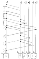
図9は、実施の形態1の上り信号の送信処理の具体例を示す図である。ONU201~204は、ONU201~204のそれぞれに設定される送信開始時刻を含むNormal GateフレームをOLT100から受信する。詳細には、Normal Gateフレームは、ONU202に設定する送信開始時刻T21、ONU203に設定する送信開始時刻T22、ONU201に設定する送信開始時刻T23、及びONU204に設定する送信開始時刻T24を含む。また、送信開始時刻T21~T24は、ガードタイムΔTlongに基づいて算出された時刻である。例えば、送信開始時刻T22は、送信開始時刻T21とONU202に割当てる帯域とガードタイムΔTlongとに基づいて算出される。また、送信開始時刻T22は、これら以外の情報に基づいて算出されてもよい。
FIG. 9 is a diagram showing a specific example of uplink signal transmission processing according to the first embodiment. The ONUs 201-204 receive from the
ONU201~204は、送信開始時刻に上り信号を送信する。
図9は、ONU202が送信した上り信号とONU203が送信した上り信号とが衝突していないことを示している。図9は、ONU203が送信した上り信号とONU201が送信した上り信号とが衝突していないことを示している。図9は、ONU201が送信した上り信号とONU204が送信した上り信号とが衝突していないことを示している。
The
FIG. 9 shows that the upstream signal transmitted by
このように、OLT100は、ガードタイムΔTlongを用いて送信開始時刻を算出することで、ONU201~204と中継器300との間で上り信号の衝突を回避できる。
Thus, the
実施の形態1の光通信システムは、複数の変調方式が混在したPONシステムにも適用できる。例えば、ONU201,202は、強度変調方式を用いて通信する。ONU203,204は、QPSK変調方式を用いて通信する。そして、中継器300の中継処理部320は、誤り訂正処理を実行する。中継器300の中継処理部330は、等化処理を実行する。ここで、強度変調方式は、第1の変調方式とも言う。QPSK変調方式は、第2の変調方式とも言う。また、第1の変調方式がQPSK変調方式と考えた場合、QPSK変調方式は、第1の変調方式と考えてもよい。
The optical communication system of
また、複数の変調方式を混在したPONシステムに含まれる中継器300は、ONU201,202が送信した上り信号を電気信号に変換せず、光信号のまま通過させてもよい。なお、複数の変調方式を混在したPONシステムに含まれる中継器300は、ONU203,204が送信した上り信号に対して、等化処理を実行する。
Further, the
中継器300は、上り信号(すなわち、光信号)をOLT100に送信している。しかし、中継器300は、ONUから受信した上り信号を電気信号に変換し、電気信号に対して中継処理を実行した後、電気信号を光信号に変換せずに、電気信号をOLT100に送信してもよい。
The
実施の形態1では、中継器300が中継処理部を2つ有する場合を例示した。実施の形態1は、中継器300が中継処理部を3つ以上有する場合にも適用できる。
In
実施の形態2.
次に、実施の形態2を説明する。実施の形態1と相違する事項を主に説明し、実施の形態1と共通する事項の説明を省略する。実施の形態2は、図1~7を参照する。
実施の形態1では、OLTにガードタイムΔTlongが設けられる。OLTは、ガードタイムΔTlongの間、上り信号を受信しない。上り信号を受信しない時間があるということは、帯域利用効率が低い。そこで、実施の形態2では、帯域利用効率を向上させる光通信システムを説明する。
Next,
In
図10は、実施の形態2の上り信号の送信処理の具体例を示す図である。後述するOLT100aは、同じ通信速度で通信するONUが連続して上り信号を送信できるように送信開始時刻を設定する。例えば、OLT100aは、ONU202に、送信開始時刻T31に上り信号を送信させる。OLT100aは、ONU201に、送信開始時刻T32に上り信号を送信させる。このように、OLT100aは、同じ通信速度で通信するONU201,202に、連続して上り信号を送信させる。また、OLT100aは、ONU204に、送信開始時刻T33に上り信号を送信させる。OLT100aは、ONU203に、送信開始時刻T34に上り信号を送信させる。このように、OLT100aは、同じ通信速度で通信するONU203,204に、連続して上り信号を送信させる。
FIG. 10 is a diagram showing a specific example of uplink signal transmission processing according to the second embodiment. The
このように、OLT100aは、同じ通信速度で通信するONUが連続して上り信号を送信できるようにすることで、ガードタイムΔTlongを設ける回数を減らすことができる。そのため、OLT100aは、帯域利用効率を向上できる。
In this way, the
次に、OLT100aについて詳細に説明する。
図11は、実施の形態2のOLTの構成を示す機能ブロック図である。OLT100aは、制御部11aを有する。制御部11aは、PON制御部150aを含む。また、制御部11aの機能は、PON制御部150aの機能と同じである。そのため、制御部11aの機能については、PON制御部150aを用いて説明する。
Next, the
FIG. 11 is a functional block diagram showing the configuration of the OLT according to the second embodiment. The
PON制御部150aは、同じ通信速度で通信するONUが連続して上り信号を送信できるように送信開始時刻を算出する。例えば、PON制御部150aは、ONU201とONU202とが連続して上り信号を送信するように、ONU201とONU202に設定する複数の送信開始時刻を算出する。また、例えば、PON制御部150aは、ONU203とONU204とが連続して上り信号を送信するように、ONU203とONU204に設定する複数の送信開始時刻を算出する。
PON制御部150aは、ガードタイムΔTlongに応じて、ONU201,202に光信号を送信させた後、ONU203,204の中で最も早く光信号の送信を開始させる時刻を算出する。また、PON制御部150aは、ガードタイムΔTlongに応じて、ONU203,204に光信号を送信させた後、ONU201,202の中で最も早く光信号の送信を開始させる時刻を算出することもできる。
図5に示される構成と同じ又は対応する図11の構成は、図5に示される符号と同じ符号を付している。
The
After causing the
11 that are the same as or correspond to those shown in FIG. 5 are labeled with the same reference numerals as those shown in FIG.
図12は、実施の形態2のOLTが実行する処理を示すフローチャートである。図12の処理は、図11を参照する。
(ステップS11)光送受信部120は、ONU201~204のそれぞれからReportフレームを受信する。PON制御部150aは、各Reportフレームから送信要求データ量を抽出する。
FIG. 12 is a flow chart showing processing executed by the OLT according to the second embodiment. The processing of FIG. 12 refers to FIG.
(Step S11) The optical transmitter/
(ステップS12)PON制御部150aは、送信要求データ量に基づいて、通信速度が10GbpsのONU201,202に割当てる帯域を算出する。
(ステップS13)PON制御部150aは、送信要求データ量に基づいて、通信速度が1GbpsのONU203,204に割当てる帯域を算出する。
(Step S12) The
(Step S13) The
(ステップS14)PON制御部150aは、ONU201,202が連続して上り信号を送信できるように送信開始時刻を算出する。なお、ONU201とONU202に設定される送信開始時刻は、どちらが先でもよい。ここで、ONU202に設定される送信開始時刻の方がONU201に設定される送信開始時刻よりも先だとする。
(Step S14) The
PON制御部150aは、ONU203,204が連続して上り信号を送信できるように送信開始時刻を算出する。なお、ONU203とONU204に設定される送信開始時刻は、どちらが先でもよい。ここで、ONU204に設定される送信開始時刻の方がONU203に設定される送信開始時刻よりも先だとする。
The
ここで、PON制御部150aは、ONU201に設定する送信開始時刻とONU201に割当てる帯域とガードタイムΔTlongとに基づいて、ONU204に設定する送信開始時刻を算出する。
Here, the
(ステップS15)PON制御部150aは、光送受信部120と信号処理部130を介して、ONU201~204に割当てる帯域とONU201~204に設定する送信開始時刻とを含むNormal GateフレームをONU201~204に送信する。
これにより、ONU201~204は、図10で示したように上り信号を送信する。
(Step S15) The
Accordingly, the
実施の形態2によれば、OLT100aは、同じ通信速度で通信するONUが連続して上り信号を送信できるようにすることで、ガードタイムΔTlongを設ける回数を減らすことができる。そのため、OLT100aは、帯域利用効率を向上できる。また、OLT100aは、帯域利用効率が向上することで、レイテンシの悪化を防ぐことができる。
According to
実施の形態3.
次に、実施の形態3を説明する。実施の形態1,2と相違する事項を主に説明し、実施の形態1,2と共通する事項の説明を省略する。
図13は、実施の形態3の光通信システムを示す図である。光通信システムは、OLT100b、光カプラ401、及びONU600を含む。光カプラ401は、OLT100bと中継器300との間に存在する。ONU600は、光カプラ401を介して、OLT100bと通信する。なお、ONU600の通信速度は、任意である。また、ONU600は、第3の子局装置とも言う。
Embodiment 3.
Next, Embodiment 3 will be described. Matters different from
FIG. 13 is a diagram showing an optical communication system according to the third embodiment. The optical communication system includes
図13では、光カプラ401を介して1つのONU(すなわち、ONU600)がOLT100bと接続する場合を示している。しかし、光カプラ401を介して複数のONUがOLT100bと接続してもよい。
FIG. 13 shows a case where one ONU (that is, ONU 600) is connected to
図14は、実施の形態3の上り信号の送信処理の具体例を示す図である。OLT100bは、実施の形態2のように、同じ通信速度で通信するONUが連続して上り信号を送信できるように送信開始時刻を設定する。
OLT100bは、ガードタイムΔTlongにONU600が送信する上り信号を受信できるように送信開始時刻を算出する。図14は、ONU600が送信開始時刻T35に上り信号の送信を開始したことを示している。
FIG. 14 is a diagram showing a specific example of uplink signal transmission processing according to the third embodiment. As in the second embodiment, the
The
このように、OLT100bは、ガードタイムΔTlongにONU600が送信する上り信号を受信することで、帯域利用効率を向上できる。
In this way, the
次に、OLT100bについて詳細に説明する。
図15は、実施の形態3のOLTの構成を示す機能ブロック図である。OLT100bは、制御部11bを有する。制御部11bは、PON制御部150bを含む。また、制御部11bの機能は、PON制御部150bの機能と同じである。そのため、制御部11bの機能については、PON制御部150bを用いて説明する。
Next, the
15 is a functional block diagram showing the configuration of an OLT according to the third embodiment; FIG. The
PON制御部150bは、ガードタイムΔTlongにONU600から上り信号を受信するために、ONU600に設定する送信開始時刻を算出する。
図5に示される構成と同じ又は対応する図15の構成は、図5に示される符号と同じ符号を付している。
The
15 that are the same as or correspond to those shown in FIG. 5 are labeled with the same reference numerals as those shown in FIG.
図16は、実施の形態3のOLTが実行する処理を示すフローチャートである。図16の処理は、図15を参照する。
(ステップS21)光送受信部120は、ONU201~204及びONU600のそれぞれからReportフレームを受信する。PON制御部150bは、各Reportフレームから送信要求データ量を抽出する。
FIG. 16 is a flow chart showing processing executed by the OLT according to the third embodiment. For the processing of FIG. 16, refer to FIG.
(Step S21) The optical transmitter/
(ステップS22)PON制御部150bは、送信要求データ量に基づいて、通信速度が10GbpsのONU201,202に割当てる帯域を算出する。
(ステップS23)PON制御部150bは、送信要求データ量に基づいて、通信速度が1GbpsのONU203,204に割当てる帯域を算出する。
(Step S22) The
(Step S23) The
(ステップS24)PON制御部150bは、ONU201,202が連続して上り信号を送信できるように送信開始時刻を算出する。なお、ONU201とONU202に設定される送信開始時刻は、どちらが先でもよい。ここで、ONU202に設定される送信開始時刻の方がONU201に設定される送信開始時刻よりも先だとする。
(Step S24) The
PON制御部150bは、ONU203,204が連続して上り信号を送信できるように送信開始時刻を算出する。なお、ONU203とONU204に設定される送信開始時刻は、どちらが先でもよい。ここで、ONU204に設定される送信開始時刻の方がONU203に設定される送信開始時刻よりも先だとする。
The
ここで、PON制御部150bは、ONU201に設定する送信開始時刻とONU201に割当てる帯域とガードタイムΔTlongとに基づいて、ONU204に設定する送信開始時刻を算出する。
Here, the
(ステップS25)PON制御部150bは、ガードタイムΔTlong内で、ONU600が送信する上り信号を受信するための送信開始時刻を算出する。また、PON制御部150bは、ONU600に割当てる帯域を算出する。
(Step S25) The
(ステップS26)PON制御部150bは、光送受信部120と信号処理部130を介して、ONU201~204及びONU600に割当てる帯域と、ONU201~204及びONU600に設定する送信開始時刻とを含むNormal GateフレームをONU201~204及びONU600に送信する。
これにより、ONU201~204及びONU600は、図14で示したように上り信号を送信する。
(Step S26) The
Accordingly, the
実施の形態3によれば、OLT100bは、ガードタイムΔTlongにONU600が送信する上り信号を受信することで、帯域利用効率を向上できる。
なお、OLT100bは、ONU600に対する帯域の割当てを毎回行わなくてもよい。すなわち、OLT100bは、ONU600に対する帯域の割当てを任意のタイミングで行ってもよい。
According to Embodiment 3, the
Note that the
実施の形態3では、OLT100bが同じ通信速度で通信するONUが連続して上り信号を送信できるように送信開始時刻を算出した後、ガードタイムΔTlongにONU600が送信する上り信号をOLT100bが受信できるようにする場合を説明した。しかし、実施の形態3は、実施の形態1にも適用できる。例えば、図9は、ガードタイムΔTlongが3つの場合を示している。OLT100bは、いずれかのガードタイムΔTlongにONU600が送信する上り信号を受信できるように送信開始時刻を算出する。
In the third embodiment, after the
また、実施の形態3の光通信システムでは、光カプラ401とONU600との間に他の中継器が存在してもよい。
Further, in the optical communication system of Embodiment 3, another repeater may exist between
実施の形態4.
次に、実施の形態4を説明する。実施の形態1と相違する事項を主に説明し、実施の形態1と共通する事項の説明を省略する。
実施の形態1~3では、管理者が中継処理テーブル111に登録される情報を端末装置500に入力し、当該情報に基づいて中継処理テーブル111が作成される。実施の形態4では、当該情報を含むフレームをOLTが受信する場合を説明する。
Next,
In the first to third embodiments, the administrator inputs information to be registered in the relay processing table 111 to the
図17は、実施の形態4の光通信システムを示す図である。光通信システムは、OLT100c及び中継器300cを含む。実施の形態4の光通信システムは、端末装置500を含まない点が実施の形態1~3の光通信システムと異なる。
FIG. 17 is a diagram showing an optical communication system according to a fourth embodiment. The optical communication system includes
図18は、実施の形態4の中継器の構成を示す機能ブロック図である。中継器300cは、中継処理情報登録部350を有する。
中継処理情報登録部350の一部又は全部は、中継器300cが有するプロセッサによって実現してもよい。中継処理情報登録部350の一部又は全部は、中継器300cが有するプロセッサが実行するプログラムのモジュールとして実現してもよい。
FIG. 18 is a functional block diagram showing the configuration of a repeater according to the fourth embodiment. The
A part or all of the relay processing
図4に示される構成と同じ又は対応する図18の構成は、図4に示される符号と同じ符号を付している。
中継処理情報登録部350は、Register Requestフレームの余剰ビットに、中継処理種別及び中継処理時間を登録する。ここで、Register Requestフレームについて説明する。
18 that are the same as or correspond to those shown in FIG. 4 are labeled with the same reference numerals as those shown in FIG.
The relay processing
図19は、実施の形態4のRegister Requestフレームのフォーマットを示す図である。Rad/Reservedは、余剰ビットである。そのため、中継処理情報登録部350は、Rad/Reservedに中継処理種別及び中継処理時間を登録する。
FIG. 19 is a diagram showing the format of a Register Request frame according to the fourth embodiment. Rad/Reserved is a surplus bit. Therefore, the relay processing
図20は、実施の形態4の中継器が実行する処理を示すフローチャートである。図20の処理は、図18,19を参照する。
(ステップS31)光/電気変換部310は、Register Requestフレームを受信する。ここで、当該Register Requestフレームは、第1の登録要求とも言う。第1の登録要求は、ONUの登録を要求するフレームである。
FIG. 20 is a flow chart showing processing executed by the repeater according to the fourth embodiment. 18 and 19 are referred to for the processing of FIG.
(Step S31) The optical/
(ステップS32)中継処理情報登録部350は、Register Requestフレームに中継処理種別及び中継処理時間を登録する。詳細には、中継処理情報登録部350は、Register RequestフレームのRad/Reservedに中継処理種別及び中継処理時間を登録する。
ここで、中継処理種別及び中継処理時間を登録したRegister Requestフレームは、第2の登録要求とも言う。
(Step S32) The relay processing
Here, the Register Request frame in which the relay processing type and relay processing time are registered is also referred to as a second registration request.
(ステップS33)電気/光変換部340は、Register RequestフレームをOLT100cに送信する。
(Step S33) The electrical/
図21は、実施の形態4のOLTの構成を示す機能ブロック図である。OLT100cは、中継処理情報抽出部160を有する。
中継処理情報抽出部160の一部又は全部は、プロセッサ101によって実現してもよい。中継処理情報抽出部160の一部又は全部は、プロセッサ101が実行するプログラムのモジュールとして実現してもよい。
FIG. 21 is a functional block diagram showing the configuration of the OLT according to the fourth embodiment. The
A part or all of the relay processing
図5に示される構成と同じ又は対応する図21の構成は、図5に示される符号と同じ符号を付している。
中継処理情報抽出部160は、Register Requestフレームから中継処理種別及び中継処理時間を抽出する。中継処理情報抽出部160は、中継処理種別及び中継処理時間に基づいて中継処理テーブル111を作成する。
21 that are the same as or correspond to those shown in FIG. 5 are labeled with the same reference numerals as those shown in FIG.
The relay processing
図22は、実施の形態4のOLTが実行する処理を示すフローチャートである。図22の処理は、図21を参照する。
(ステップS41)光送受信部120は、中継器300cが送信したRegister Requestフレームを受信する。
FIG. 22 is a flow chart showing processing executed by an OLT according to the fourth embodiment. The processing of FIG. 22 refers to FIG.
(Step S41) The optical transmitter/
(ステップS42)中継処理情報抽出部160は、信号処理部130を介して、Register Requestフレームを受信する。中継処理情報抽出部160は、Register Requestフレームから中継処理種別及び中継処理時間(例えば、SPA及びSPB)を抽出する。
(Step S<b>42 ) The relay processing
(ステップS43)中継処理情報抽出部160は、中継処理種別及び中継処理時間に基づいて中継処理テーブル111を作成する。中継処理情報抽出部160は、中継処理テーブル111を記憶部110に格納する。
(Step S43) The relay processing
実施の形態4によれば、OLT100cは、中継処理種別及び中継処理時間を中継器300cから受信する。そのため、OLT100cは、中継処理種別及び中継処理時間に基づいて中継処理テーブル111を作成できる。そのため、管理者は、中継処理テーブル111に登録される情報を端末装置500に入力する作業を行わなくて済む。よって、光通信システムは、管理者の作業負担を軽減できる。
According to the fourth embodiment, the
以上に説明した各実施の形態における特徴は、互いに適宜組み合わせることができる。また、実施の形態1~4は、10G-EPONシステムに中継器が含まれる場合を例示した。しかし、実施の形態1~4は、10G-EPONシステム以外の光通信システムにも適用できる。
The features of the embodiments described above can be combined as appropriate. Further,
10 上位ネットワーク、 11,11a,11b 制御部、 21 Discovery Gateフレーム、 22 Register Requestフレーム、 100,100a,100b,100c OLT、 101 プロセッサ、 102 揮発性記憶装置、 103 不揮発性記憶装置、 110 記憶部、 111 中継処理テーブル、 120 光送受信部、 130 信号処理部、 140 ガードタイム算出部、 150,150a,150b PON制御部、 160 中継処理情報抽出部、 201,202,203,204 ONU、 300,300c 中継器、 310 光/電気変換部、 320,330 中継処理部、 340 電気/光変換部、 350 中継処理情報登録部、 400,401 光カプラ、 500 端末装置、 600 ONU、 900 OLT、 901,902 ONU、 903 中継器。
10
Claims (13)
前記第1の子局装置は、第1の通信方式で通信し、
前記第2の子局装置は、第2の通信方式で通信し、
前記中継器は、
前記第1の子局装置及び前記第2の子局装置と、前記親局装置との間に存在し、
前記第1の子局装置が送信した光信号を受信した場合、受信した光信号に対して処理を行い、前記第2の子局装置が送信した光信号を受信した場合、受信した光信号に対して処理を行い、
前記親局装置は、前記第1の子局装置が送信した光信号に対して前記中継器が処理を実行する時間である第1の中継処理時間と、前記第2の子局装置が送信した光信号に対して前記中継器が処理を実行する時間である第2の中継処理時間とに基づいて算出されたガードタイムに応じて、前記第1の子局装置に光信号を送信させた後、次に、前記第2の子局装置に光信号の送信を開始させる時刻である送信開始時刻を算出する、
光通信システム。 An optical communication system including a first slave station device, a second slave station device, a repeater, and a master station device,
The first slave station device communicates in a first communication scheme,
The second slave station device communicates by a second communication method,
The repeater is
exists between the first slave station device and the second slave station device and the master station device,
When the optical signal transmitted by the first slave station device is received, the received optical signal is processed, and when the optical signal transmitted by the second slave station device is received, the received optical signal is process the
The master station device sets a first relay processing time, which is a time during which the repeater executes processing on the optical signal transmitted by the first slave station device, and After causing the first slave station device to transmit an optical signal in accordance with a guard time calculated based on a second relay processing time, which is a time during which the repeater performs processing on the optical signal , next, calculating a transmission start time, which is a time to cause the second slave station device to start transmitting an optical signal;
Optical communication system.
請求項1に記載の光通信システム。 The master station device delays the transmission start time of the second slave station device calculated according to the guard time from the transmission start time of the second slave station device calculated without using the guard time. ,
The optical communication system according to claim 1.
請求項1又は2に記載の光通信システム。 The guard time is a value larger than the difference between the first relay processing time and the second relay processing time.
The optical communication system according to claim 1 or 2.
前記第2の子局装置と同じ通信方式で通信する複数の子局装置である第2の子局装置群と、
をさらに含み、
前記親局装置は、
前記第1の子局装置群が連続して光信号を送信するように、前記第1の子局装置群に光信号の送信を開始させる時刻である複数の送信開始時刻を算出し、前記第2の子局装置群が連続して光信号を送信するように、前記第2の子局装置群に光信号の送信を開始させる時刻である複数の送信開始時刻を算出し、かつ前記ガードタイムに応じて、前記第1の子局装置群に光信号を送信させた後、前記第2の子局装置群の中で最も早く光信号の送信を開始させる時刻を算出する、
請求項1から3のいずれか1項に記載の光通信システム。 a first slave station device group, which is a plurality of slave station devices that communicate in the same communication method as the first slave station device;
a second slave station device group, which is a plurality of slave station devices communicating in the same communication method as the second slave station device;
further comprising
The master station device
calculating a plurality of transmission start times that are times at which the first group of slave station devices start transmitting optical signals so that the first group of slave station devices continuously transmit optical signals; calculating a plurality of transmission start times, which are times at which the second group of slave station devices start transmitting optical signals so that the two slave station device groups continuously transmit optical signals, and the guard time; Calculating the earliest time to start transmission of optical signals among the second group of slave station devices after causing the first group of slave station devices to transmit optical signals according to
The optical communication system according to any one of claims 1 to 3.
前記光カプラを介して、前記親局装置と通信する第3の子局装置と、
をさらに含み、
前記親局装置は、前記ガードタイムに前記第3の子局装置から光信号を受信するために、前記第3の子局装置に光信号の送信を開始させる時刻である送信開始時刻を算出する、
請求項1から4のいずれか1項に記載の光通信システム。 an optical coupler existing between the repeater and the master station device;
a third slave station device that communicates with the master station device via the optical coupler;
further comprising
The master station apparatus calculates a transmission start time, which is a time at which the third slave station apparatus starts transmission of an optical signal in order to receive the optical signal from the third slave station apparatus during the guard time. ,
The optical communication system according to any one of claims 1 to 4.
子局装置の登録を要求する第1の登録要求を受信した場合、前記第1の中継処理時間と前記第2の中継処理時間とを前記第1の登録要求に登録し、
前記第1の中継処理時間と前記第2の中継処理時間とを前記第1の登録要求に登録した情報である第2の登録要求を前記親局装置に送信し、
前記親局装置は、前記第1の中継処理時間と前記第2の中継処理時間とを前記第2の登録要求から抽出する、
請求項1から5のいずれか1項に記載の光通信システム。 The repeater is
registering the first relay processing time and the second relay processing time in the first registration request when receiving a first registration request requesting registration of a slave station device;
transmitting a second registration request, which is information in which the first relay processing time and the second relay processing time are registered in the first registration request, to the master station device;
The master station device extracts the first relay processing time and the second relay processing time from the second registration request.
The optical communication system according to any one of claims 1 to 5.
前記第2の通信方式は、前記第1の通信速度よりも遅い第2の通信速度である、
請求項1から6のいずれか1項に記載の光通信システム。 The first communication method is a first communication speed,
The second communication method is a second communication speed slower than the first communication speed,
An optical communication system according to any one of claims 1 to 6.
前記第2の通信方式は、前記第1の通信速度よりも速い第2の通信速度である、
請求項1から6のいずれか1項に記載の光通信システム。 The first communication method is a first communication speed,
The second communication method is a second communication speed faster than the first communication speed,
An optical communication system according to any one of claims 1 to 6.
前記第2の通信方式は、第2の変調方式である、
請求項1から6のいずれか1項に記載の光通信システム。 The first communication scheme is a first modulation scheme,
The second communication scheme is a second modulation scheme,
An optical communication system according to any one of claims 1 to 6.
前記中継器を介して、前記第1の子局装置と、前記第2の子局装置とが送信した光信号を受信する光送受信部と、
前記第1の子局装置が送信した光信号に対して前記中継器が処理を実行する時間である第1の中継処理時間と、前記第2の子局装置が送信した光信号に対して前記中継器が処理を実行する時間である第2の中継処理時間とに基づいて算出されたガードタイムに応じて、前記第1の子局装置に光信号を送信させた後、次に、前記第2の子局装置に光信号の送信を開始させる時刻である送信開始時刻を算出する制御部と、
を有する光通信装置。 A first slave station device that communicates by a first communication method, a second slave station device that communicates by a second communication method, a master station device, and the first slave station device and the second slave station device and an optical communication device that is the master station device in an optical communication system that includes a repeater that relays an optical signal between the master station device and the master station device,
an optical transmission/reception unit that receives optical signals transmitted by the first slave station device and the second slave station device via the repeater;
a first relay processing time, which is a time for the repeater to process the optical signal transmitted by the first slave station device; After causing the first slave station device to transmit the optical signal in accordance with the guard time calculated based on the second relay processing time, which is the time during which the repeater executes the processing, a control unit that calculates a transmission start time, which is a time at which the slave station device of No. 2 starts transmission of an optical signal;
An optical communication device having
請求項10に記載の光通信装置。 further comprising a guard time calculation unit that calculates the guard time based on the first relay processing time and the second relay processing time;
11. The optical communication device according to claim 10.
前記第1の子局装置が送信した光信号に対して前記中継器が処理を実行する時間である第1の中継処理時間と、前記第2の子局装置が送信した光信号に対して前記中継器が処理を実行する時間である第2の中継処理時間とに基づいて算出されたガードタイムに応じて、前記第1の子局装置に光信号を送信させた後、次に、前記第2の子局装置に光信号の送信を開始させる時刻である送信開始時刻を算出する、
制御方法。 A first slave station device that communicates by a first communication method, a second slave station device that communicates by a second communication method, a master station device, and the first slave station device and the second slave station device and an optical communication device that is the master station device in an optical communication system that includes a repeater that relays an optical signal between the master station device and the master station device,
a first relay processing time, which is a time for the repeater to process the optical signal transmitted by the first slave station device; After causing the first slave station device to transmit the optical signal in accordance with the guard time calculated based on the second relay processing time, which is the time during which the repeater executes the processing, Calculating the transmission start time, which is the time to start the transmission of the optical signal by the slave station device of 2,
control method.
前記第1の子局装置が送信した光信号に対して前記中継器が処理を実行する時間である第1の中継処理時間と、前記第2の子局装置が送信した光信号に対して前記中継器が処理を実行する時間である第2の中継処理時間とに基づいて算出されたガードタイムに応じて、前記第1の子局装置に光信号を送信させた後、次に、前記第2の子局装置に光信号の送信を開始させる時刻である送信開始時刻を算出する、
処理を実行させる制御プログラム。 A first slave station device that communicates by a first communication method, a second slave station device that communicates by a second communication method, a master station device, and the first slave station device and the second slave station device and an optical communication device that is the master station device in an optical communication system that includes a repeater that relays an optical signal between the master station device and the master station device,
a first relay processing time, which is a time for the repeater to process the optical signal transmitted by the first slave station device; After causing the first slave station device to transmit the optical signal in accordance with the guard time calculated based on the second relay processing time, which is the time during which the repeater executes the processing, Calculating the transmission start time, which is the time to start the transmission of the optical signal by the slave station device of 2,
A control program that causes a process to be executed.
Priority Applications (1)
| Application Number | Priority Date | Filing Date | Title |
|---|---|---|---|
| JP2018170141A JP7122914B2 (en) | 2018-09-12 | 2018-09-12 | Optical communication system, optical communication device, control method, and control program |
Applications Claiming Priority (1)
| Application Number | Priority Date | Filing Date | Title |
|---|---|---|---|
| JP2018170141A JP7122914B2 (en) | 2018-09-12 | 2018-09-12 | Optical communication system, optical communication device, control method, and control program |
Publications (2)
| Publication Number | Publication Date |
|---|---|
| JP2020043499A JP2020043499A (en) | 2020-03-19 |
| JP7122914B2 true JP7122914B2 (en) | 2022-08-22 |
Family
ID=69798841
Family Applications (1)
| Application Number | Title | Priority Date | Filing Date |
|---|---|---|---|
| JP2018170141A Active JP7122914B2 (en) | 2018-09-12 | 2018-09-12 | Optical communication system, optical communication device, control method, and control program |
Country Status (1)
| Country | Link |
|---|---|
| JP (1) | JP7122914B2 (en) |
Citations (5)
| Publication number | Priority date | Publication date | Assignee | Title |
|---|---|---|---|---|
| WO2010116411A1 (en) | 2009-04-07 | 2010-10-14 | 三菱電機株式会社 | Station-side communication device, optical communication system, and resource allocation method |
| JP2011160195A (en) | 2010-02-01 | 2011-08-18 | Nippon Telegr & Teleph Corp <Ntt> | Band allocating device, and band allocating method |
| WO2012090274A1 (en) | 2010-12-27 | 2012-07-05 | 三菱電機株式会社 | Relay device, station side optical communication device, communication system, and bandwidth allocation method |
| JP2014161120A (en) | 2014-05-30 | 2014-09-04 | Sumitomo Electric Ind Ltd | Relaying method for pon optical communication system |
| JP2014195192A (en) | 2013-03-29 | 2014-10-09 | Hitachi Ltd | Dynamic band allocation method, olt and pon system |
-
2018
- 2018-09-12 JP JP2018170141A patent/JP7122914B2/en active Active
Patent Citations (5)
| Publication number | Priority date | Publication date | Assignee | Title |
|---|---|---|---|---|
| WO2010116411A1 (en) | 2009-04-07 | 2010-10-14 | 三菱電機株式会社 | Station-side communication device, optical communication system, and resource allocation method |
| JP2011160195A (en) | 2010-02-01 | 2011-08-18 | Nippon Telegr & Teleph Corp <Ntt> | Band allocating device, and band allocating method |
| WO2012090274A1 (en) | 2010-12-27 | 2012-07-05 | 三菱電機株式会社 | Relay device, station side optical communication device, communication system, and bandwidth allocation method |
| JP2014195192A (en) | 2013-03-29 | 2014-10-09 | Hitachi Ltd | Dynamic band allocation method, olt and pon system |
| JP2014161120A (en) | 2014-05-30 | 2014-09-04 | Sumitomo Electric Ind Ltd | Relaying method for pon optical communication system |
Also Published As
| Publication number | Publication date |
|---|---|
| JP2020043499A (en) | 2020-03-19 |
Similar Documents
| Publication | Publication Date | Title |
|---|---|---|
| US10389472B2 (en) | Optical line terminal communication method and device with data structure | |
| US9793993B2 (en) | Method and apparatus of delivering upstream data in ethernet passive optical network over coaxial network | |
| US9112612B2 (en) | Relay device, station-side optical communication device, communication system, and bandwidth allocation method | |
| JP2009152916A (en) | Network system and OLT | |
| JP2009152915A (en) | Network system, ONU and OLT | |
| JP5541327B2 (en) | Relay device, station side device, and communication system and communication method using the relay device | |
| US20130343761A1 (en) | Access Equipment that Runs Ethernet Passive Optical Network (PON) or Ethernet PON Over Coax Network | |
| US20090252492A1 (en) | Optical communication system , and optical communication method and communication unit therefor | |
| WO2019141037A1 (en) | Communication network and related devices | |
| WO2013189462A2 (en) | Method for prolonging transmission distance of passive optical network system and optical line terminal | |
| JP6459588B2 (en) | Access control system, access control method, master station device, and slave station device | |
| JP4913876B2 (en) | Bandwidth allocation apparatus and bandwidth allocation method | |
| US20180359235A1 (en) | Transmission apparatus and communication method | |
| JP7122914B2 (en) | Optical communication system, optical communication device, control method, and control program | |
| JP2019022196A (en) | Optical communication system | |
| JP2011166328A (en) | Optical transmission system, optical line terminal and upward transmission control method | |
| JP7158310B2 (en) | Optical communication device and control method | |
| JP6827435B2 (en) | Optical communication device, control method, and control program | |
| JP5661665B2 (en) | Branched optical access system and method | |
| WO2016157626A1 (en) | Station-side device and communication control method | |
| JP5661664B2 (en) | Branched optical access system and method | |
| JP6085244B2 (en) | Optical communication system, signal transmission control method, and subscriber-side optical line terminator | |
| JP2015170991A (en) | Wavelength monitoring method, wavelength monitoring system and master node | |
| JP2015154211A (en) | Master station device, communication system, communication control method and control device | |
| JP2014204368A (en) | Master station device, control device, communication system and band control method |
Legal Events
| Date | Code | Title | Description |
|---|---|---|---|
| A621 | Written request for application examination |
Free format text: JAPANESE INTERMEDIATE CODE: A621 Effective date: 20210326 |
|
| A977 | Report on retrieval |
Free format text: JAPANESE INTERMEDIATE CODE: A971007 Effective date: 20211220 |
|
| A131 | Notification of reasons for refusal |
Free format text: JAPANESE INTERMEDIATE CODE: A131 Effective date: 20220104 |
|
| TRDD | Decision of grant or rejection written | ||
| A01 | Written decision to grant a patent or to grant a registration (utility model) |
Free format text: JAPANESE INTERMEDIATE CODE: A01 Effective date: 20220712 |
|
| A61 | First payment of annual fees (during grant procedure) |
Free format text: JAPANESE INTERMEDIATE CODE: A61 Effective date: 20220809 |
|
| R150 | Certificate of patent or registration of utility model |
Ref document number: 7122914 Country of ref document: JP Free format text: JAPANESE INTERMEDIATE CODE: R150 |