JP7122054B1 - Micro drape and its mounting method - Google Patents
Micro drape and its mounting method Download PDFInfo
- Publication number
- JP7122054B1 JP7122054B1 JP2022530266A JP2022530266A JP7122054B1 JP 7122054 B1 JP7122054 B1 JP 7122054B1 JP 2022530266 A JP2022530266 A JP 2022530266A JP 2022530266 A JP2022530266 A JP 2022530266A JP 7122054 B1 JP7122054 B1 JP 7122054B1
- Authority
- JP
- Japan
- Prior art keywords
- lens
- drape
- lens cap
- protective
- micro
- Prior art date
- Legal status (The legal status is an assumption and is not a legal conclusion. Google has not performed a legal analysis and makes no representation as to the accuracy of the status listed.)
- Active
Links
- 238000000034 method Methods 0.000 title claims description 10
- 230000001681 protective effect Effects 0.000 claims abstract description 93
- 230000003287 optical effect Effects 0.000 claims abstract description 22
- 230000004323 axial length Effects 0.000 claims description 3
- 230000000149 penetrating effect Effects 0.000 claims description 2
- 238000004804 winding Methods 0.000 description 18
- 238000010586 diagram Methods 0.000 description 14
- 230000002093 peripheral effect Effects 0.000 description 9
- 238000001356 surgical procedure Methods 0.000 description 3
- 230000008878 coupling Effects 0.000 description 2
- 238000010168 coupling process Methods 0.000 description 2
- 238000005859 coupling reaction Methods 0.000 description 2
- 230000004313 glare Effects 0.000 description 2
- 238000005286 illumination Methods 0.000 description 2
- 239000000463 material Substances 0.000 description 2
- 239000011347 resin Substances 0.000 description 2
- 229920005989 resin Polymers 0.000 description 2
- 240000001973 Ficus microcarpa Species 0.000 description 1
- 229930182556 Polyacetal Natural products 0.000 description 1
- 239000004698 Polyethylene Substances 0.000 description 1
- 230000000694 effects Effects 0.000 description 1
- 239000011521 glass Substances 0.000 description 1
- 230000000399 orthopedic effect Effects 0.000 description 1
- 239000004417 polycarbonate Substances 0.000 description 1
- 229920000515 polycarbonate Polymers 0.000 description 1
- -1 polyethylene Polymers 0.000 description 1
- 229920000573 polyethylene Polymers 0.000 description 1
- 229920006324 polyoxymethylene Polymers 0.000 description 1
- 230000001954 sterilising effect Effects 0.000 description 1
- 238000004659 sterilization and disinfection Methods 0.000 description 1
- 238000003466 welding Methods 0.000 description 1
- 229910052724 xenon Inorganic materials 0.000 description 1
- FHNFHKCVQCLJFQ-UHFFFAOYSA-N xenon atom Chemical compound [Xe] FHNFHKCVQCLJFQ-UHFFFAOYSA-N 0.000 description 1
Images


Classifications
-
- G—PHYSICS
- G02—OPTICS
- G02B—OPTICAL ELEMENTS, SYSTEMS OR APPARATUS
- G02B21/00—Microscopes
- G02B21/0004—Microscopes specially adapted for specific applications
- G02B21/0012—Surgical microscopes
-
- A—HUMAN NECESSITIES
- A61—MEDICAL OR VETERINARY SCIENCE; HYGIENE
- A61B—DIAGNOSIS; SURGERY; IDENTIFICATION
- A61B46/00—Surgical drapes
- A61B46/10—Surgical drapes specially adapted for instruments, e.g. microscopes
-
- A—HUMAN NECESSITIES
- A61—MEDICAL OR VETERINARY SCIENCE; HYGIENE
- A61B—DIAGNOSIS; SURGERY; IDENTIFICATION
- A61B90/00—Instruments, implements or accessories specially adapted for surgery or diagnosis and not covered by any of the groups A61B1/00 - A61B50/00, e.g. for luxation treatment or for protecting wound edges
- A61B90/20—Surgical microscopes characterised by non-optical aspects
-
- G—PHYSICS
- G02—OPTICS
- G02B—OPTICAL ELEMENTS, SYSTEMS OR APPARATUS
- G02B21/00—Microscopes
- G02B21/02—Objectives
-
- G—PHYSICS
- G02—OPTICS
- G02B—OPTICAL ELEMENTS, SYSTEMS OR APPARATUS
- G02B21/00—Microscopes
- G02B21/06—Means for illuminating specimens
-
- G—PHYSICS
- G02—OPTICS
- G02B—OPTICAL ELEMENTS, SYSTEMS OR APPARATUS
- G02B21/00—Microscopes
- G02B21/24—Base structure
-
- G—PHYSICS
- G02—OPTICS
- G02B—OPTICAL ELEMENTS, SYSTEMS OR APPARATUS
- G02B27/00—Optical systems or apparatus not provided for by any of the groups G02B1/00 - G02B26/00, G02B30/00
- G02B27/0006—Optical systems or apparatus not provided for by any of the groups G02B1/00 - G02B26/00, G02B30/00 with means to keep optical surfaces clean, e.g. by preventing or removing dirt, stains, contamination, condensation
Landscapes
- Health & Medical Sciences (AREA)
- Physics & Mathematics (AREA)
- Surgery (AREA)
- Life Sciences & Earth Sciences (AREA)
- General Physics & Mathematics (AREA)
- Optics & Photonics (AREA)
- General Health & Medical Sciences (AREA)
- Chemical & Material Sciences (AREA)
- Analytical Chemistry (AREA)
- Biomedical Technology (AREA)
- Veterinary Medicine (AREA)
- Heart & Thoracic Surgery (AREA)
- Medical Informatics (AREA)
- Molecular Biology (AREA)
- Animal Behavior & Ethology (AREA)
- Public Health (AREA)
- Engineering & Computer Science (AREA)
- Nuclear Medicine, Radiotherapy & Molecular Imaging (AREA)
- Oral & Maxillofacial Surgery (AREA)
- Pathology (AREA)
- Microscoopes, Condenser (AREA)
- Sampling And Sample Adjustment (AREA)
- Packages (AREA)
Abstract
手術顕微鏡への取付作業をさらに容易化したマイクロドレープを提供する。マイクロドレープは、手術顕微鏡の対物レンズのハウジングに着脱されるレンズキャップと、対物レンズを保護する保護レンズと、手術顕微鏡を覆うドレープ本体とを備える。レンズキャップは、円筒の周方向の一部が開放されて、対物レンズの光軸に直交する断面が円弧形状である。マイクロドレープは、自然状態のレンズキャップの内径寸法より外径寸法が大きい円筒で、保護レンズを保持する保護レンズホルダと、レンズキャップに対して保護レンズホルダを、光軸に直交する回動軸線周りに回動可能に支持するジョイントとを備える。保護レンズホルダは、レンズキャップの内側に進入して、レンズキャップを弾性拡径させる着脱位置と、レンズキャップの内側から対物レンズと反対側に抜け出して、レンズキャップを縮径させると共に、光軸に対して保護レンズを傾斜させる使用位置とに回動する。To provide a micro drape which is easier to attach to a surgical microscope. The micro drape includes a lens cap attached to and detached from the housing of the objective lens of the surgical microscope, a protective lens that protects the objective lens, and a drape body that covers the surgical microscope. The lens cap has an arc-shaped cross section perpendicular to the optical axis of the objective lens, with a portion of the cylinder being open in the circumferential direction. The micro drape is a cylinder whose outer diameter is larger than the inner diameter of the lens cap in its natural state. and a joint rotatably supported on the The protective lens holder enters into the inside of the lens cap and elastically expands the diameter of the lens cap to an attachment/detachment position, and exits from the inside of the lens cap to the opposite side of the objective lens to contract the diameter of the lens cap and align with the optical axis. It rotates to the use position in which the protective lens is tilted against it.
Description
本発明は、手術顕微鏡を覆うマイクロドレープに関する。 The present invention relates to microdrapes covering surgical microscopes.
脳神経外科、耳鼻咽喉科、整形外科や眼科では、手術顕微鏡を用いて術野を拡大しながら、手術が行われることがある。手術は清潔操作で行わなければならないが、手術顕微鏡そのものを滅菌するのは難しいため、手術の度に使い捨てのマイクロドレープで手術顕微鏡を覆って、清潔野を確保するのが一般的である(例えば、特許文献1-4を参照)。 In neurosurgery, otorhinolaryngology, orthopedics, and ophthalmology, surgery is sometimes performed while enlarging the operative field using a surgical microscope. Surgery must be performed with clean operation, but since it is difficult to sterilize the surgical microscope itself, it is common to cover the surgical microscope with a disposable micro-drape to ensure a clean field (e.g., sterilization). , see Patent Documents 1-4).
一般的なマイクロドレープは、手術顕微鏡の対物レンズに着脱されるレンズキャップと、レンズキャップを保持すると共に手術顕微鏡を覆う袋状のドレープ本体とで構成されている。また、特許文献5には、直径の異なる対物レンズに装着可能なレンズキャップの様々なバリエーションと、手術顕微鏡の入射光の反射やグレアを防ぐために光軸に対して保護レンズの角度を変更する構成とが開示されている。
A typical micro drape is composed of a lens cap that can be attached to and detached from the objective lens of the surgical microscope, and a bag-like drape body that holds the lens cap and covers the surgical microscope. In addition,
しかしながら、特許文献5のマイクロドレープでは、対物レンズにレンズキャップを取り付ける作業と、保護レンズの角度を調整する作業とを別々に行う必要がある。そのため、手術顕微鏡にマイクロドレープを取り付ける作業が煩雑になる。
However, in the micro drape of
本発明は、このような従来技術の課題を解決するためになされたものであり、その目的は、手術顕微鏡への取付作業をさらに容易化したマイクロドレープを提供することにある。 SUMMARY OF THE INVENTION The present invention has been made to solve the problems of the prior art, and it is an object of the present invention to provide a micro-drape that can be easily attached to a surgical microscope.
本発明は、前記課題を解決するため、手術顕微鏡の対物レンズのハウジングに着脱されるレンズキャップと、前記対物レンズを保護する保護レンズと、前記手術顕微鏡を覆うドレープ本体とを備えるマイクロドレープにおいて、前記レンズキャップは、円筒の周方向の一部が開放されて、前記対物レンズの光軸に直交する断面が円弧形状であり、自然状態の前記レンズキャップの内径寸法より外径寸法が大きい円筒で、前記保護レンズを保持する保護レンズホルダと、前記レンズキャップに対して前記保護レンズホルダを、前記光軸に直交する回動軸線周りに回動可能に支持するジョイントとを備え、前記保護レンズホルダは、前記レンズキャップの内側に進入して、前記レンズキャップを弾性拡径させる着脱位置と、前記レンズキャップの内側から前記対物レンズと反対側に抜け出して、前記レンズキャップを縮径させると共に、前記光軸に対して前記保護レンズを傾斜させる使用位置とに回動することを特徴とする。 In order to solve the above problems, the present invention provides a micro drape comprising a lens cap detachable from a housing of an objective lens of a surgical microscope, a protective lens protecting the objective lens, and a drape body covering the surgical microscope, The lens cap is a cylinder which is partially open in the circumferential direction, has an arc-shaped cross section perpendicular to the optical axis of the objective lens, and has an outer diameter larger than the inner diameter of the lens cap in a natural state. a protective lens holder that holds the protective lens; and a joint that supports the protective lens holder with respect to the lens cap so as to be rotatable around a rotational axis perpendicular to the optical axis, wherein the protective lens holder enters the inside of the lens cap and elastically expands the diameter of the lens cap to an attachment/detachment position; exits from the inside of the lens cap to the opposite side of the objective lens to contract the diameter of the lens cap; It is characterized by rotating to a use position in which the protective lens is tilted with respect to the optical axis.
本発明によれば、手術顕微鏡への取付作業をさらに容易化したマイクロドレープを得ることができる。 According to the present invention, it is possible to obtain a micro drape which is easier to attach to a surgical microscope.
以下、実施形態に係るマイクロドレープ10を図面に基づいて説明する。なお、以下に記載する本発明の実施形態は、本発明を具体化する際の一例を示すものであって、本発明の範囲を実施形態の記載の範囲に限定するものではない。従って、本発明は、実施形態に種々の変更を加えて実施することができる。
Hereinafter, the
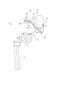
図1は、手術顕微鏡1の要部及びマイクロドレープ10の概略構成図である。図1に示すように、手術顕微鏡1は、互いに回動可能に連結された複数のアーム2、3、4、5と、アーム5の先端に取り付けられた対物レンズ6及び接眼レンズ7とを主に備える。そして、アーム2~5の接合部分が相対的に回動することによって、術野に対面する位置に対物レンズ6を配置することができる。そして、医師(術者)が接眼レンズ7を覗くことによって、拡大された術野を観察することができる。
FIG. 1 is a schematic configuration diagram of a main part of an
また、対物レンズ6は、凸レンズである。そして、対物レンズ6は、円筒形状のハウジング8の内側に取り付けられている。すなわち、図1に一点鎖線で示す対物レンズ6の光軸L0は、ハウジング8の軸方向に一致する。
Also, the
さらに、手術顕微鏡1は、照明装置(例えば、LED、キセノンランプ)を備える。照明装置から照射された光は、アーム2~5内に収容された光学系(レンズ、ミラーなど)を介して対物レンズ6を通過し、術野に向けて照射される。この光が術野で反射して再び対物レンズ6に入射することによって、医師が術野を観察することができる。照明装置による光の照射方向は、例えば、光軸L0に対して3~6°程度傾けられている。
Furthermore, the
手術中に術部に触れるまたは触れる可能性のある全ての器具は滅菌する必要がある。しかしながら、手術顕微鏡1そのものを滅菌するのは難しいので、手術の度に使い捨てのマイクロドレープ10で手術顕微鏡1を覆う。マイクロドレープ10は滅菌された状態で梱包されており、手術室で梱包を解いて手術顕微鏡1に被せられる。
All instruments that touch or may touch the surgical site during surgery must be sterilized. However, since it is difficult to sterilize the
図2は、マイクロドレープ10の下方斜視図である。図3は、マイクロドレープ10の上方斜視図である。図1~図3に示すように、本実施形態に係るマイクロドレープ10は、ドレープ本体20と、レンズキャップユニット30とを主に備える。なお、図2及び図3では、レンズキャップユニット30の図示を省略している。
FIG. 2 is a bottom perspective view of the micro-drape 10. FIG. FIG. 3 is a top perspective view of the micro-drape 10. FIG. As shown in FIGS. 1 to 3, the
ドレープ本体20は、透明または半透明の素材(例えば、ポリエチレン)で形成されたシート状の部材である。図1~図3に示すように、ドレープ本体20は、袋状部21と、帯状部22とで構成される。ドレープ本体20は、長手方向(「延設方向」に一致する。)と短手方向(「幅方向」に一致する。)とを有する長方形状の外形を呈する。延設方向及び幅方向は、ドレープ本体20の厚み方向に直交する平面において、互いに直交する方向である。
The
袋状部21は、シートが二重に重ねられた袋形状の部分である。より詳細には、袋状部21は、上面シート23と、下面シート24とを重ねて構成されている。上面シート23及び下面シート24は、各々が矩形状(長方形状)の外形を呈する。また、上面シート23及び下面シート24の対応する三辺は、互いに接合されている。一方、上面シート23及び下面シート24の他の一辺は、互いに離間して、開口25を画定するように周方向に連続する。
The bag-
また、袋状部21には、開口25の外縁を示す目印26が付加されている。目印26は、開口25の外縁に添付された色付きのシール、開口25の外縁に塗布された色付きのインクなど、透明または半透明のドレープ本体20のうち、開口25の外縁部を作業者が容易に特定できるものであれば、どのようなものでもよい。
Further, a
さらに、袋状部21の下面シート24には、貫通孔27が形成されている。貫通孔27は、下面シート24を厚み方向に貫通する。また、貫通孔27は、下面シート24の概ね中央に形成されている。そして、貫通孔27には、レンズキャップユニット30が取り付けられる。例えば、下面シート24の貫通孔27の周縁を画定する部分が、レンズキャップユニット30の外周面に溶着される。
Furthermore, through
帯状部22は、上面シート23の開口25を画定する辺から、ドレープ本体20の長手方向に沿って延設されている。図1に示すように、手術顕微鏡1の全体を覆う必要がある場合(例えば、外科用)、帯状部22の延設方向の長さは、幅方向より長い帯状に構成される。なお、図2及び図3では、帯状部22の延設方向の長さを短縮して図示している。一方、手術顕微鏡1の対物レンズ6周辺のみを覆えばよい場合(例えば、眼科用)、帯状部22の延設方向の長さは、幅方向より短くてもよい。
The belt-
帯状部22の幅方向の両辺には、複数の結合部28a、28b、28c、29a、29b、29cが取り付けられている。より詳細には、結合部28a~28bは、帯状部22の幅方向の一方側の辺において、延設方向に所定の間隔を隔てて設けられている。結合部29a~29bは、帯状部22の幅方向の他方側の辺において、延設方向に所定の間隔を隔てて設けられている。
A plurality of
図1に示すように、帯状部22を手術顕微鏡1の上面に沿わせて、対応する結合部28a&29a、28b&29b、28c&29cを結合することによって、帯状部22で手術顕微鏡1を覆うことができる。結合部28a~28c、29a~29cは、紐、スナップボタン、線ファスナー、面ファスナー、ゴム紐など、互いに結合することができれば、どのようなものでもよい。
As shown in FIG. 1, the
なお、前述の説明では、ドレープ本体20を、上面シート23及び下面シート24で構成される袋状部21と、帯状部22とに区分している。しかしながら、独立した上面シート23、下面シート24、及び帯状部22を接合して、ドレープ本体20が形成されている必要はない。例えば、帯状のシートの延設方向の一部を折り返して、重ね合わされた部分の幅方向の両端部を溶着することによって、ドレープ本体20が形成されてもよい。この場合、上面シート23及び下面シート24の接合された三辺のうち、一辺が帯状のシートの折り返された部分に相当し、残りの二辺が溶着された部分に相当する。
In the above description, the
すなわち、袋状部21は、一端に開口25が形成された袋状であればよい。また、帯状部22は、袋状部21の開口25の周方向の一部から延設されていればよい。さらに、袋状部21のうち、帯状部22が形成されている領域が上面シート23で、その他の領域が下面シート24となる。
In other words, the bag-
図4は、マイクロドレープ10を三つ折りした状態を示す図である。図3に示すように、マイクロドレープ10は、幅方向に離間した位置で各々が延設方向に延びる仮想線L1、L2に沿って折り返されることによって、図4に示すように三つ折りにされる。以下、ドレープ本体20のうち、仮想線L1、L2の間の中央部の領域を「領域C」と表記し、仮想線L1、L2を挟んで領域Cに隣接する両端部の領域を「領域R」、「領域L」と表記する。
FIG. 4 is a diagram showing a state in which the
領域C、R、Lの幅方向の寸法は、概ね一致する。また、レンズキャップユニット30の取付位置(すなわち、貫通孔27の位置)は、領域Cである。そして、領域Rを仮想線L1で上面シート23側に折り返し、その後に領域Lを仮想線L2で上面シート23側に折り返す。これにより、図4に示すように、領域C、R、Lが互いに重なるように三つ折りされる。但し、領域R、Lを折り返す順序は、逆順でもよい。
The dimensions in the width direction of the regions C, R, and L are substantially the same. Also, the mounting position of the lens cap unit 30 (that is, the position of the through hole 27) is the area C. As shown in FIG. Then, the region R is folded back toward the
図5は、三つ折りされたマイクロドレープ10を巻取り部材40に巻き取った状態を示す図である。巻取り部材40は、例えば、円柱形状(または、円筒形状)の棒状の部材である。そして、図4に示すマイクロドレープ10を、帯状部22の延設端側(袋状部21と反対側の端部)から袋状部21側に向かって巻取り部材40に巻き取ることによって、図5に示すようにロール状になる。
FIG. 5 shows a state in which the
なお、レンズキャップユニット30がロールの外周面側に位置するように、巻取り部材40に巻き取るのが望ましい。換言すれば、三つ折りされたマイクロドレープ10のうち、レンズキャップユニット30が取り付けられた側と反対側面に巻取り部材40を当接させて巻き取るのが望ましい。但し、巻取方向は逆向きでもよい。また、マイクロドレープ10は、図5に示すように巻き取られた状態で梱包されていてもよいし、手術顕微鏡1に取り付けられる前に作業者によって巻取り部材40に巻き取られてもよい。
It is desirable that the
次に、図6~図9を参照して、マイクロドレープ10を手術顕微鏡1に取り付ける方法を説明する。図6は、手術顕微鏡1に取り付ける直前のマイクロドレープ10の状態を示す図である。図7は、レンズキャップユニット30をハウジング8に取り付けた状態を示す図である。図8は、巻取り部材40からドレープ本体20を繰り出した状態を示す図である。図9は、マイクロドレープ10を手術顕微鏡1に取り付ける手順(すなわち、取付方法)を示すフローチャートである。
Next, a method for attaching the
まず、作業者は、図6に示すように、巻取り部材40に巻き取られたドレープ本体20を開口25の位置まで繰り出す(S1)。換言すれば、作業者は、袋状部21及び帯状部22のうちの袋状部21のみを、巻取り部材40から繰り出す。作業者は、例えば、目印26が露出するまで、ドレープ本体20を巻取り部材40から繰り出せばよい。これにより、袋状部21の折り返された領域R、Lを幅方向に展開可能になる。
First, as shown in FIG. 6, the operator draws out the
次に、作業者は、図7に示すように、展開した袋状部21の内側からレンズキャップユニット30を露出させて、対物レンズ6のハウジング8に装着する(S2)。レンズキャップユニット30の形状及びハウジング8への取付方法は、図10~図16を参照して後述する。
Next, as shown in FIG. 7, the operator exposes the
次に、作業者は、図8に示すように、手術顕微鏡1の上面に沿って、巻取り部材40から帯状部22を繰り出す(S3)。次に、作業者は、帯状部22の折り返された領域R、Lを幅方向に展開する(S4)。さらに、作業者は、図1に示すように、帯状部22で手術顕微鏡1を覆った状態で、対応する結合部28a&29a、28b&29b、28c&29cを結合する(S5)。これにより、手術顕微鏡1に対するマイクロドレープ10の取付作業が完了する。
Next, as shown in FIG. 8, the operator feeds out the band-shaped
図10は、保護レンズホルダ32を着脱位置にしたレンズキャップユニット30の下方斜視図である。図11は、保護レンズホルダ32を着脱位置にしたレンズキャップユニット30の上方斜視図である。図12は、保護レンズホルダ32を使用位置にしたレンズキャップユニット30の下方斜視図である。図13は、保護レンズホルダ32を使用位置にしたレンズキャップユニット30の上方斜視図である。
FIG. 10 is a bottom perspective view of the
図10~図13に示すように、レンズキャップユニット30は、レンズキャップ31と、保護レンズホルダ32と、ジョイント33と、保護レンズ34とを主に備える。レンズキャップユニット30は、ドレープ本体20の貫通孔27に取り付けられる。一例として、保護レンズホルダ32または保護レンズ34の外周面に、貫通孔27の周縁部が溶着される。他の例として、軸方向に分割された保護レンズホルダ32で、ドレープ本体20の厚み方向の両側から貫通孔27の周縁部を挟み込んでもよい。すなわち、レンズキャップ31は、保護レンズホルダ32または保護レンズ34を介して、間接的にドレープ本体20に取り付けられる。
As shown in FIGS. 10 to 13, the
レンズキャップ31は、対物レンズ6のハウジング8に着脱される部分である。レンズキャップ31は、円筒の周方向の一部を開放した形状である。すなわち、レンズキャップ31は、対物レンズ6の光軸L0(軸方向)に直交する断面が円弧形状(C型形状)となっている。レンズキャップ31は、弾性変形能を有する樹脂(例えば、ポリカーボネート、ポリアセタール等)で形成されている。これにより、レンズキャップ31は、開放された部分が接離するように、弾性的に拡縮可能になっている。
The
保護レンズホルダ32は、円筒形状の外形を呈する。保護レンズホルダ32の外形寸法は、自然状態(拡径されていない状態)のレンズキャップ31の内径寸法より大きく設定されている。また、保護レンズホルダ32の軸方向の一端(図14の下端)は、軸方向に対して直交している。一方、保護レンズホルダ32の軸方向の他端(図14の上端)は、軸方向に対して傾斜している。すなわち、保護レンズホルダ32の周方向において、保護レンズホルダ32の軸方向の長さは異なっている。そして、保護レンズホルダ32は、軸方向の一端側において、保護レンズ34を保持している。また、保護レンズホルダ32は、ジョイント33を介してレンズキャップ31に回動可能に取り付けられている。
The
ジョイント33は、光軸L0に直交する回動軸線L3周りに、レンズキャップ31に対して保護レンズホルダ32を回動可能に支持している。より詳細には、ジョイント33は、レンズキャップ31の内周面と、保護レンズホルダ32の外周面のうちの軸方向の長さが最も短い位置とに取り付けられている。すなわち、保護レンズホルダ32の軸方向の長さは、円筒の周方向において、ジョイント33の位置から遠いほど長くなっている。そして、保護レンズホルダ32は、図10及び図11に示す着脱位置と、図12及び図13に示す使用位置との間を、レンズキャップ31に対して回動する。
The joint 33 rotatably supports the
着脱位置は、レンズキャップユニット30をハウジング8に着脱する際の保護レンズホルダ32の位置である。着脱位置の保護レンズホルダ32は、レンズキャップ31の内側に進入して、レンズキャップ31を弾性拡径させる。これにより、レンズキャップ31の内径寸法は、想定されるハウジング8の外形寸法より大きくなる。また、着脱位置の保護レンズホルダ32は、光軸L0と直交した状態で保護レンズ34を保持する。
The attaching/detaching position is the position of the
使用位置は、マイクロドレープ10で覆った手術顕微鏡1を使用する際の保護レンズホルダ32の位置である。使用位置の保護レンズホルダ32は、レンズキャップ31の内側から対物レンズ6と反対側に抜け出して、レンズキャップ31を縮径させる。これにより、レンズキャップ31の内周面がハウジング8の外周面に密着して、レンズキャップユニット30がハウジング8に固定される。また、使用位置の保護レンズホルダ32は、光軸L0に対して保護レンズ34を傾斜させる。
The use position is the position of the
保護レンズ34は、光を透過する材料(例えば、ガラス、樹脂など)で形成された平板形状のレンズである。但し、保護レンズ34の形状は平板形状に限定されず、凸形状に隆起した曲面レンズでもよい。保護レンズ34は、保護レンズホルダ32の軸方向の一端に固定されている。すなわち、保護レンズ34は、保護レンズホルダ32及びジョイント33を介して、レンズキャップ31に間接的に取り付けられている。
The
保護レンズ34は、手術顕微鏡1の対物レンズ6を保護する。より詳細には、レンズキャップユニット30をハウジング8に装着したとき、保護レンズ34は、対物レンズ6に対面する。そして、保護レンズ34を通過した外光が対物レンズ6に入射する。また、保護レンズ34は、光軸L0に対して傾斜することによって、手術顕微鏡1の入射光の反射やグレアを防止する。
次に、図14~図17を参照して、手術顕微鏡1のハウジング8にレンズキャップユニット30を取り付ける方法(すなわち、図9のステップS21~S22)を説明する。図14は、レンズキャップユニット30をハウジング8に取り付ける直前の状態を示す図である。図15は、レンズキャップ31をハウジング8に外挿した状態を示す図である。図16は、レンズキャップ31をハウジング8に固定した状態を示す図である。
Next, a method of attaching the
まず、作業者は、図14に示すように、袋状部21(図14では図示省略)の内側から露出させたレンズキャップ31を、ハウジング8の下方にセットする。このときの保護レンズホルダ32は、着脱位置である。これにより、弾性拡径したレンズキャップ31の内径寸法は、ハウジング8の外形寸法より大きい状態になっている。
First, as shown in FIG. 14, the operator sets the
次に、作業者は、図15に示すように、保護レンズホルダ32を着脱位置にした状態で、レンズキャップ31を軸方向からハウジング8に外挿する(S21)。この状態では、未だレンズキャップ31がハウジング8に固定されていないので、作業者はレンズキャップ31の位置を保持しておく必要がある。
Next, as shown in FIG. 15, the operator axially inserts the
次に、作業者は、図16に示すように、保護レンズホルダ32を着脱位置から使用位置に回動させる(S22)。これにより、レンズキャップ31が縮径してハウジング8に固定される。また、対物レンズ6の光軸L0に対して、保護レンズ34が傾斜した状態で保持される。
Next, the operator rotates the
上記の実施形態によれば、例えば以下の作用効果を奏する。 According to the above embodiment, for example, the following operational effects are obtained.
上記の実施形態によれば、保護レンズホルダ32を着脱位置から使用位置に回動させるだけで、レンズキャップ31がハウジング8に固定されると共に、対物レンズ6の光軸L0に対して保護レンズ34を傾斜させることができる。また、レンズキャップ31を弾性拡径させた状態でハウジング8に軸方向から外挿させることができるので、レンズキャップ31をハウジング8に抵抗なく取り付けることができる。その結果、手術顕微鏡1へのレンズキャップユニット30の取付作業が容易になる。
According to the above-described embodiment, the
また、上記の実施形態によれば、保護レンズホルダ32の軸方向の長さが最も短い位置にジョイント33を取り付けることによって、保護レンズホルダ32がレンズキャップ31から抜け出すまでの角度(すなわち、着脱位置と使用位置との角度差)が小さくなる。その結果、使用位置における保護レンズ34の傾斜角度の選択肢が広がる。
Further, according to the above embodiment, by attaching the joint 33 to the position where the length of the
なお、保護レンズホルダ32の使用位置は一箇所でなくてもよい。換言すれば、選択可能な保護レンズ34の傾斜角度は、一種類に限定されない。他の例として、保護レンズホルダ32は、光軸L0に対して保護レンズ34を第1角度(例えば、60°)に傾斜させる第1使用位置と、光軸L0に対して保護レンズ34を第2角度(例えば、45°)に傾斜させる第2使用位置とに、レンズキャップ31に対して回動してもよい。なお、第1角度及び第2角度は、互いに異なる角度であれば、前述の例に限定されない。
In addition, the use position of the
また、上記の実施形態では、保護レンズホルダ32の軸方向の他端側に保護レンズ34が取り付けられている例を説明した。しかしながら、保護レンズホルダ32で保護レンズ34を保持する具体的な方法は、前述の例に限定されない。他の例として、保護レンズホルダ32には、円筒を厚み方向に貫通するスリットが形成されていてもよい。そして、保護レンズ34は、スリットに挿抜可能であってもよい。すなわち、保護レンズホルダ32は、スリットに挿入された保護レンズ34を保持してもよい。これにより、保護レンズ34を用途に応じて容易に交換することができる。
Further, in the above embodiment, an example in which the
また、上記の実施形態によれば、袋状部21及び帯状部22でドレープ本体20を構成することによって、例えば図7及び図8に示すように、マイクロドレープ10を手術顕微鏡1に取り付ける過程において、ドレープ本体20が垂れ下がって床に触れることを防止できる。その結果、清潔な状態を保ったまま、マイクロドレープ10を手術顕微鏡1に容易に取り付けることができる。
Further, according to the above-described embodiment, the drape
また、上記の実施形態によれば、開口25の外縁に目印26を付加することによって、ドレープ本体20を開口25の位置まで巻取り部材40から繰り出す作業(図9のステップS1)が容易になる。すなわち、作業者は、図9のステップS1において、例えば図6に示すように、目印26が露出するまでドレープ本体20を繰り出せばよい。
Further, according to the above-described embodiment, adding the
また、上記の実施形態によれば、帯状部22の幅方向の両辺に結合部28a~28c、29a~29cを設けたので、手術顕微鏡1の上面に沿って配置した帯状部22でアーム2~5などを覆って、容易に固定することができる。また、帯状部22の延設方向の複数の位置に結合部28a~28c、29a~29cを設けることによって、帯状部22で手術顕微鏡1を覆ったときの隙間を少なくできる。
Further, according to the above-described embodiment, since the
また、上記の実施形態によれば、巻取り部材40に巻き取ったマイクロドレープ10(ドレープ本体20)を、手術顕微鏡1の上面に沿って繰り出すことによって、清潔な状態を保ったまま、ドレープ本体20を手術顕微鏡1に被せる作業が容易になる。
Further, according to the above-described embodiment, the micro drape 10 (drape main body 20) wound on the winding
さらに、上記の実施形態によれば、マイクロドレープ10(ドレープ本体20)を三つ折りにした状態で巻取り部材40に巻き取ることによって、使用する前のマイクロドレープ10を小さくすることができる。これにより、マイクロドレープ10の輸送や保管が容易になる。
Furthermore, according to the above-described embodiment, the micro drape 10 (drape body 20) can be made smaller before use by winding the micro drape 10 (drape main body 20) folded in three on the winding
なお、マイクロドレープ10(ドレープ本体20)を折り返す具体的な方法は、図3及び図4の例に限定されない。図17は、領域R、Lを重ねずにマイクロドレープ10を三つ折りした状態を示す図である。図18は、図17のマイクロドレープ10をさらに折りたたんだ状態を示す図である。なお、上記の実施形態との共通点の詳細な説明は省略し、相違点を中心に説明する。
A specific method for folding back the micro drape 10 (drape main body 20) is not limited to the examples shown in FIGS. FIG. 17 is a diagram showing a state in which the
図17に示すように、マイクロドレープ10は、幅方向に離間した位置で各々が延設方向に延びる仮想線L4、L5に沿って、上面シート23側に折り返されてもよい。仮想線L4、L5は、図3に示す仮想線L1、L2と比較して、幅方向に離間している。すなわち、領域Cの幅方向の寸法は、領域R、Lより大きい(2倍)。これにより、図17の下段に示すように、マイクロドレープ10は、領域R、Lそれぞれの幅方向の端部がドレープ本体20の中央で接するように三つ折りされる。
As shown in FIG. 17, the
また、図18に示すように、図17の下段ように三つ折りされたマイクロドレープ10は、幅方向に離間した位置で各々が延設方向に延びる仮想線L6、L7に沿って、上面シート23側にさらに折り返されてもよい。これにより、マイクロドレープ10を幅方向にさらに小型化することができる。
As shown in FIG. 18, the
さらに、本発明に係るマイクロドレープ10は、図2~図5に示すドレープ本体20と、図10~図16に示すレンズキャップユニット30との組み合わせに限定されない。他の例として、マイクロドレープ10は、図2~図5に示すドレープ本体20と、一般的な円筒形状のレンズキャップとで構成されていてもよい。さらに他の例として、マイクロドレープは、一般的な袋状(筒状)のドレープ本体と、図10~図16に示すレンズキャップユニット30とで構成されていてもよい。
Furthermore, the
1…手術顕微鏡、2~5…アーム、6…対物レンズ、7…接眼レンズ、8…ハウジング、10…マイクロドレープ、20…ドレープ本体、21…袋状部、22…帯状部、23…上面シート、24…下面シート、25…開口、26…目印、27…貫通孔、28a~28c,29a~29c…結合部、30…レンズキャップユニット、31…レンズキャップ、32…保護レンズホルダ、33…ジョイント、34…保護レンズ、40…巻取り部材
DESCRIPTION OF
Claims (5)
前記対物レンズを保護する保護レンズと、
前記手術顕微鏡を覆うドレープ本体とを備えるマイクロドレープにおいて、
前記レンズキャップは、円筒の周方向の一部が開放されて、前記対物レンズの光軸に直交する断面が円弧形状であり、
自然状態の前記レンズキャップの内径寸法より外径寸法が大きい円筒で、前記保護レンズを保持する保護レンズホルダと、
前記レンズキャップに対して前記保護レンズホルダを、前記光軸に直交する回動軸線周りに回動可能に支持するジョイントとを備え、
前記保護レンズホルダは、
前記レンズキャップの内側に進入して、前記レンズキャップを弾性拡径させる着脱位置と、
前記レンズキャップの内側から前記対物レンズと反対側に抜け出して、前記レンズキャップを縮径させると共に、前記光軸に対して前記保護レンズを傾斜させる使用位置とに回動することを特徴とするマイクロドレープ。a lens cap to be attached to and detached from the housing of the objective lens of the surgical microscope;
a protective lens that protects the objective lens;
A drape body covering the surgical microscope,
the lens cap is partially open in the circumferential direction of the cylinder and has an arc-shaped cross section perpendicular to the optical axis of the objective lens;
a protective lens holder which is a cylinder having an outer diameter dimension larger than an inner diameter dimension of the lens cap in a natural state and holds the protective lens;
a joint that supports the protective lens holder with respect to the lens cap so as to be rotatable about a rotation axis orthogonal to the optical axis;
The protective lens holder is
an attachment/detachment position for entering the inside of the lens cap and elastically expanding the diameter of the lens cap;
The micro lens is characterized in that it comes out from the inside of the lens cap to the side opposite to the objective lens, reduces the diameter of the lens cap, and rotates to a use position in which the protective lens is tilted with respect to the optical axis. drape.
前記着脱位置の前記保護レンズホルダは、前記光軸と直交した状態で前記保護レンズを保持することを特徴とするマイクロドレープ。The microdrape of claim 1, wherein
The micro drape, wherein the protective lens holder at the attachment/detachment position holds the protective lens in a state perpendicular to the optical axis.
前記保護レンズホルダの軸方向の長さは、円筒の周方向において、前記ジョイントの位置から遠いほど長くなっていることを特徴とするマイクロドレープ。The microdrape of claim 1, wherein
The micro drape, wherein the axial length of the protective lens holder increases with increasing distance from the joint in the circumferential direction of the cylinder.
前記ドレープ本体は、
矩形状の上面シート及び下面シートの三辺が互いに接合され、残りの一辺が開口を画定する袋状部と、
前記上面シートの前記開口を画定する辺から延設された帯状の帯状部とを備え、
前記レンズキャップは、前記下面シートを厚み方向に貫通する貫通孔に取り付けられていることを特徴とするマイクロドレープ。The microdrape of claim 1, wherein
The drape body is
a bag-shaped portion in which three sides of a rectangular top sheet and a bottom sheet are joined together and the remaining one side defines an opening;
a strip-shaped portion extending from a side defining the opening of the top sheet,
A micro drape, wherein the lens cap is attached to a through hole penetrating through the lower sheet in a thickness direction.
前記保護レンズホルダを前記着脱位置にした状態で、前記レンズキャップを軸方向から前記ハウジングに外挿し、
前記保護レンズホルダを前記着脱位置から前記使用位置に回動させることによって、縮径した前記レンズキャップを前記ハウジングに固定することを特徴とする取付方法。
An attachment method for attaching the microdrape according to claim 1 to the surgical microscope,
inserting the lens cap axially onto the housing while the protective lens holder is in the attaching/detaching position;
and fixing the lens cap with a reduced diameter to the housing by rotating the protective lens holder from the attachment/detachment position to the use position.
Applications Claiming Priority (1)
| Application Number | Priority Date | Filing Date | Title |
|---|---|---|---|
| PCT/JP2022/021089 WO2023228242A1 (en) | 2022-05-23 | 2022-05-23 | Microdrape and method for attaching same |
Publications (2)
| Publication Number | Publication Date |
|---|---|
| JP7122054B1 true JP7122054B1 (en) | 2022-08-19 |
| JPWO2023228242A1 JPWO2023228242A1 (en) | 2023-11-30 |
Family
ID=82929856
Family Applications (1)
| Application Number | Title | Priority Date | Filing Date |
|---|---|---|---|
| JP2022530266A Active JP7122054B1 (en) | 2022-05-23 | 2022-05-23 | Micro drape and its mounting method |
Country Status (7)
| Country | Link |
|---|---|
| US (1) | US11883125B2 (en) |
| JP (1) | JP7122054B1 (en) |
| KR (1) | KR102574806B1 (en) |
| CN (1) | CN116456929B (en) |
| IL (1) | IL301779A (en) |
| TW (1) | TWI822589B (en) |
| WO (1) | WO2023228242A1 (en) |
Cited By (1)
| Publication number | Priority date | Publication date | Assignee | Title |
|---|---|---|---|---|
| DE102023110099A1 (en) | 2023-04-20 | 2024-10-24 | avateramedical GmBH | Sterile cover of a robot unit for robot-assisted surgery |
Citations (5)
| Publication number | Priority date | Publication date | Assignee | Title |
|---|---|---|---|---|
| US4266663A (en) * | 1979-11-13 | 1981-05-12 | Carl Zeiss, Inc. | Surgical drape for an operating microscope |
| US6876503B1 (en) * | 2003-10-28 | 2005-04-05 | Contour Fabricators, Inc. | Microscope drape lens protective cover assembly |
| JP2008545506A (en) * | 2005-06-06 | 2008-12-18 | エイビーエス エムイーディ インコーポレイテッド | Surgical microscope drape with removable lens assembly |
| JP2010512851A (en) * | 2006-12-13 | 2010-04-30 | マイクロテック メディカル,インコーポレイテッド | Microscope drape lens cover system and assembly method |
| WO2022003806A1 (en) * | 2020-06-30 | 2022-01-06 | 株式会社名優 | Microdrape |
Family Cites Families (12)
| Publication number | Priority date | Publication date | Assignee | Title |
|---|---|---|---|---|
| US6024454A (en) * | 1998-12-04 | 2000-02-15 | Ph Medical, Inc. | Microscope drape system |
| US7234824B2 (en) * | 2003-09-22 | 2007-06-26 | Langley Nicholas M | Glare-elimination device for surgical microscopes |
| US8155755B2 (en) * | 2005-08-29 | 2012-04-10 | Dignity Health | Disposable sheath for telementry leads of a monitoring device |
| US20100238551A1 (en) * | 2009-03-19 | 2010-09-23 | Hubbs Charles M | Surgical microscope drape lens for reducing glare |
| AR081564A1 (en) * | 2011-06-02 | 2012-10-03 | Desarrollos Tecnologicos Device S R L | AN EXTRACTION DEVICE FOR ELEMENTS CONTAINED IN CAVES, USING A BAG FOR EXTRACTION AND AN APPLICATOR |
| JP5632496B2 (en) | 2013-02-25 | 2014-11-26 | 三鷹光器株式会社 | Micro drape |
| KR102510796B1 (en) * | 2014-03-17 | 2023-03-17 | 인튜어티브 서지컬 오퍼레이션즈 인코포레이티드 | Surgical drape and systems including surgical drape and attachment sensor |
| CN204709007U (en) * | 2015-06-15 | 2015-10-21 | 杨峂 | The aseptic isolating and protecting grip assembly of Dispoable medical |
| DE102015225009A1 (en) | 2015-12-11 | 2017-06-14 | Carl Zeiss Meditec Ag | Protective glass adapter for a surgical microscope |
| KR102522154B1 (en) | 2016-03-15 | 2023-04-17 | 에스케이하이닉스 주식회사 | Controller of semiconductor memory device and operating method thereof |
| CN110292483B (en) * | 2019-07-05 | 2021-09-17 | 山东省眼科医院 | A light filtering protective structure for ophthalmology laser surgery |
| KR102472298B1 (en) | 2020-07-02 | 2022-11-30 | 박우진 | Pillow type neck retractor with laser medical treatment |
-
2022
- 2022-05-23 KR KR1020237009472A patent/KR102574806B1/en active Active
- 2022-05-23 CN CN202280006956.5A patent/CN116456929B/en active Active
- 2022-05-23 US US18/024,105 patent/US11883125B2/en active Active
- 2022-05-23 JP JP2022530266A patent/JP7122054B1/en active Active
- 2022-05-23 WO PCT/JP2022/021089 patent/WO2023228242A1/en unknown
-
2023
- 2023-02-14 TW TW112105160A patent/TWI822589B/en active
- 2023-03-29 IL IL301779A patent/IL301779A/en unknown
Patent Citations (5)
| Publication number | Priority date | Publication date | Assignee | Title |
|---|---|---|---|---|
| US4266663A (en) * | 1979-11-13 | 1981-05-12 | Carl Zeiss, Inc. | Surgical drape for an operating microscope |
| US6876503B1 (en) * | 2003-10-28 | 2005-04-05 | Contour Fabricators, Inc. | Microscope drape lens protective cover assembly |
| JP2008545506A (en) * | 2005-06-06 | 2008-12-18 | エイビーエス エムイーディ インコーポレイテッド | Surgical microscope drape with removable lens assembly |
| JP2010512851A (en) * | 2006-12-13 | 2010-04-30 | マイクロテック メディカル,インコーポレイテッド | Microscope drape lens cover system and assembly method |
| WO2022003806A1 (en) * | 2020-06-30 | 2022-01-06 | 株式会社名優 | Microdrape |
Cited By (1)
| Publication number | Priority date | Publication date | Assignee | Title |
|---|---|---|---|---|
| DE102023110099A1 (en) | 2023-04-20 | 2024-10-24 | avateramedical GmBH | Sterile cover of a robot unit for robot-assisted surgery |
Also Published As
| Publication number | Publication date |
|---|---|
| KR102574806B1 (en) | 2023-09-04 |
| CN116456929B (en) | 2023-10-31 |
| TWI822589B (en) | 2023-11-11 |
| US11883125B2 (en) | 2024-01-30 |
| IL301779A (en) | 2023-05-01 |
| EP4306073A1 (en) | 2024-01-17 |
| TW202345756A (en) | 2023-12-01 |
| US20230414308A1 (en) | 2023-12-28 |
| JPWO2023228242A1 (en) | 2023-11-30 |
| CN116456929A (en) | 2023-07-18 |
| WO2023228242A1 (en) | 2023-11-30 |
Similar Documents
| Publication | Publication Date | Title |
|---|---|---|
| ES2936467T3 (en) | Surgical Microscope Case with Removable Lens Mount | |
| US5433221A (en) | Windowed self-centering drape for surgical camera | |
| CA2784751C (en) | Medical lens assemblies and sterile drapes with a lens assembly | |
| JP7122054B1 (en) | Micro drape and its mounting method | |
| BRPI0719986B1 (en) | MICROSCOPE FIELD COUPLING SYSTEM AND METHOD | |
| US20060139753A1 (en) | Microscope drape coupling system and method | |
| ES2541904T3 (en) | Surgical Microscope Cloth Set | |
| JP6749532B1 (en) | Micro drape | |
| JP7145559B1 (en) | Micro drape and its mounting method | |
| JP5632496B2 (en) | Micro drape | |
| JP2988981B2 (en) | Surgical microscope drape | |
| JP2006343670A (en) | Objective protector and microscopic observation method | |
| CN119300786A (en) | Micro protective bag | |
| JP2017113322A (en) | Display device | |
| JP2017113321A (en) | Display device |
Legal Events
| Date | Code | Title | Description |
|---|---|---|---|
| A621 | Written request for application examination |
Free format text: JAPANESE INTERMEDIATE CODE: A621 Effective date: 20220524 |
|
| A871 | Explanation of circumstances concerning accelerated examination |
Free format text: JAPANESE INTERMEDIATE CODE: A871 Effective date: 20220524 |
|
| TRDD | Decision of grant or rejection written | ||
| A01 | Written decision to grant a patent or to grant a registration (utility model) |
Free format text: JAPANESE INTERMEDIATE CODE: A01 Effective date: 20220712 |
|
| A61 | First payment of annual fees (during grant procedure) |
Free format text: JAPANESE INTERMEDIATE CODE: A61 Effective date: 20220801 |
|
| R150 | Certificate of patent or registration of utility model |
Ref document number: 7122054 Country of ref document: JP Free format text: JAPANESE INTERMEDIATE CODE: R150 |