JP7120548B2 - SENSING DIRECTION ESTIMATION DEVICE, SENSING DIRECTION ESTIMATION METHOD AND PROGRAM - Google Patents
SENSING DIRECTION ESTIMATION DEVICE, SENSING DIRECTION ESTIMATION METHOD AND PROGRAM Download PDFInfo
- Publication number
- JP7120548B2 JP7120548B2 JP2019170144A JP2019170144A JP7120548B2 JP 7120548 B2 JP7120548 B2 JP 7120548B2 JP 2019170144 A JP2019170144 A JP 2019170144A JP 2019170144 A JP2019170144 A JP 2019170144A JP 7120548 B2 JP7120548 B2 JP 7120548B2
- Authority
- JP
- Japan
- Prior art keywords
- sensor
- sensor terminal
- sensing direction
- terminal
- sensing
- Prior art date
- Legal status (The legal status is an assumption and is not a legal conclusion. Google has not performed a legal analysis and makes no representation as to the accuracy of the status listed.)
- Active
Links
Images


Classifications
-
- Y—GENERAL TAGGING OF NEW TECHNOLOGICAL DEVELOPMENTS; GENERAL TAGGING OF CROSS-SECTIONAL TECHNOLOGIES SPANNING OVER SEVERAL SECTIONS OF THE IPC; TECHNICAL SUBJECTS COVERED BY FORMER USPC CROSS-REFERENCE ART COLLECTIONS [XRACs] AND DIGESTS
- Y02—TECHNOLOGIES OR APPLICATIONS FOR MITIGATION OR ADAPTATION AGAINST CLIMATE CHANGE
- Y02D—CLIMATE CHANGE MITIGATION TECHNOLOGIES IN INFORMATION AND COMMUNICATION TECHNOLOGIES [ICT], I.E. INFORMATION AND COMMUNICATION TECHNOLOGIES AIMING AT THE REDUCTION OF THEIR OWN ENERGY USE
- Y02D30/00—Reducing energy consumption in communication networks
- Y02D30/70—Reducing energy consumption in communication networks in wireless communication networks
Landscapes
- Indicating Or Recording The Presence, Absence, Or Direction Of Movement (AREA)
- Length Measuring Devices With Unspecified Measuring Means (AREA)
Description
本発明は、センシング方向推定装置、センシング方向推定方法及びプログラムに関する。 The present invention relates to a sensing direction estimation device, a sensing direction estimation method, and a program.
近年、小型の無線機能付きセンサを監視対象領域にばら撒いてネットワーク化し、様々なアプリケーションに用いようとする試みがなされている。特に、センサ位置の事前設計や登録が必要なく、また、センサそのものもGPSなどの測位機能を搭載していない、廉価、低消費電力、低機能なものを用いる状況を想定することが望ましい。 In recent years, attempts have been made to scatter small sensors with wireless functions over a monitoring target area, network them, and use them for various applications. In particular, it is desirable to assume a situation in which a low-cost, low-power-consumption, low-function sensor that does not require prior design or registration of the sensor position and does not have a positioning function such as GPS is used.
そのようなセンサの一例として小型の距離センサがある。距離センサは、指向性を持っており、或る角度方向(以下、「センシング方向」という。)に線分状のセンシング領域を持つ。センシング領域内に物体が入ってきたとき、距離センサは自身とその物体までの距離を計測し、計測結果(以下、「センシングデータ」という。)を、ネットワーク上の計算サーバ等に送信する。 One example of such sensors is a small distance sensor. A distance sensor has directivity and has a linear sensing area in a certain angular direction (hereinafter referred to as "sensing direction"). When an object enters the sensing area, the distance sensor measures the distance between itself and the object, and transmits the measurement result (hereinafter referred to as "sensing data") to a calculation server or the like on the network.
ばら撒かれた距離センサを用いたアプリケーションの一つに、対象物の形状推定技術がある。非特許文献1では、直線運動する車などの対象物について、全体形状を推定する方法が提案されている。一般的に距離センサはランダムにばら撒かれるため、各距離センサの位置やセンシング方向は未知である。そこで、非特許文献1では、多数の距離センサから得られるセンシングデータを集積し解析することで、まず各距離センサのセンシング方向を算出し、それに基づいて形状推定を行っている。距離センサのセンシング方向を算出することは、対象物の形状推定に限らず、距離センサの位置特定、センサ間の時刻同期など、他のアプリケーションを考える上でも重要である。
One of the applications using scattered distance sensors is the shape estimation technology of an object. Non-Patent
前述のように、距離センサのセンシング方向は一般的に未知であるため、従来技術による対象物の形状推定は、距離センサのセンシング方向の推定を必要とする。ところが、非特許文献1で提案するセンシング方向の推定方法は、距離センサから得られるセンシングデータの時刻に関する高階微分値の計算が必要であるため、センシングデータのノイズに極めて弱いという課題がある。実際、非特許文献1の中でも、センシングデータが大きなノイズを含む場合、センシング方向の推定精度が極めて低くなることが言及されており、結果として対象物の形状推定精度が低下、あるいは推定自体が困難となる。
As mentioned above, the sensing direction of the range sensor is generally unknown, so prior art object shape estimation requires estimation of the sensing direction of the range sensor. However, the method of estimating the sensing direction proposed in
本発明は、上記の点に鑑みてなされたものであって、センシング方向の推定についてセンシングデータのノイズに対する耐性を高めることを目的とする。 SUMMARY OF THE INVENTION The present invention has been made in view of the above points, and an object of the present invention is to improve resistance to noise in sensing data in estimating a sensing direction.
そこで上記課題を解決するため、センシング方向推定装置は、複数のセンサ端末のそれぞれによって測定された、移動する物体と当該センサ端末との距離についての複数の測定値に基づいて、前記各センサ端末のセンシング方向の推定値を計算する推定部を有し、前記推定部は、前記複数のセンサ端末のうちの第1のセンサ端末と他の各センサ端末との組ごとに、前記第1のセンサ端末との組に係る第2のセンサ端末の測定値群を非剛体変換し、非剛体変換後の測定値群と、前記第1のセンサ端末の測定値との距離を最小化する処理を繰り返すことで、前記第1のセンサ端末及び前記第2のセンサ端末それぞれのセンシング方向の推定値を計算する。 Therefore, in order to solve the above problem, a sensing direction estimating device provides a plurality of sensor terminals based on a plurality of measured values of the distance between a moving object and the sensor terminal. an estimating unit for calculating an estimated value of a sensing direction, the estimating unit for each set of a first sensor terminal and each of the other sensor terminals among the plurality of sensor terminals; Repeating the process of non-rigidly transforming the measured value group of the second sensor terminal according to the set of and minimizing the distance between the measured value group after non-rigid transformation and the measured value of the first sensor terminal , compute an estimate of the sensing direction of each of the first sensor terminal and the second sensor terminal.
センシング方向の推定についてセンシングデータのノイズに対する耐性を高めることができる。 It is possible to increase the resistance to noise in sensing data for estimation of the sensing direction.
以下、図面に基づいて本発明の実施の形態を説明する。図1は、本発明の実施の形態におけるセンシング方向推定システムの構成例を示す図である。本実施の形態におけるセンシング方向推定システムは、センシング方向推定装置10と、センサ端末d1~センサ端末dN~のN~個(複数)のセンサ端末(以下、それぞれを区別しない場合「センサ端末d」という。)とを含む。センシング方向推定装置10と各センサ端末dとは、有線又は無線のネットワークを介して接続される。なお、N~は、図中においてNの上の「~」が付加された記号に相当する。
BEST MODE FOR CARRYING OUT THE INVENTION An embodiment of the present invention will be described below based on the drawings. FIG. 1 is a diagram showing a configuration example of a sensing direction estimation system according to an embodiment of the present invention. The sensing direction estimation system according to the present embodiment comprises a sensing
各センサ端末dは、監視対象領域内を移動する物体(以下、「対象物T」という。)を検出するとともに、対象物Tまでの距離を測定する距離センサである。各センサ端末dは、シャープな指向性を持つ距離センサであって、対象物Tとの距離がrmax以下のとき、対象物Tまでの距離r(0≦r≦rmax)を測定結果(以下、「センシングデータ」という。)として得て、センシングデータをセンシング方向推定装置10に送信する。本実施の形態において、各センサ端末dのセンシング領域(対象物Tを検知可能な範囲)は、それぞれ特定の方向(以下、「センシング方向」という。)を有し、長さがrmaxである線分としてモデル化される。なお、各センサ端末dの配置位置はランダムである。すなわち、各センサ端末dは、ランダムに決定される配置位置に撒かれる。
Each sensor terminal d is a distance sensor that detects an object (hereinafter referred to as “target object T”) moving within the monitored area and measures the distance to the target object T. FIG. Each sensor terminal d is a distance sensor with sharp directivity, and when the distance to the object T is r max or less, the distance r (0≦r≦r max ) to the object T is measured as a result ( hereinafter referred to as “sensing data”), and transmits the sensing data to the sensing
センシング方向推定装置10は、「非剛体変換ICP(Iterative Closest Point)アルゴリズム」を含む、後述される処理を実行して、各センサ端末dのセンシング方向を推定する1以上のコンピュータである。センシング方向推定結果は、センシング方向推定装置10からユーザ端末20に送信される。あるいは、当該推定結果は、非特許文献1における、対象物Tの形状推定に用いられてもよい。
The sensing
ユーザ端末20は、センシング方向推定装置10における推定結果を表示する端末である。
The
図2は、本発明の実施の形態において与えられる問題設定を説明するための図である。なお、以下で説明する問題設定は一例に過ぎず、適用可能な問題設定はこれに限られるわけではない。 FIG. 2 is a diagram for explaining problem setting given in the embodiment of the present invention. Note that the problem setting described below is merely an example, and the applicable problem setting is not limited to this.
対象物Tは、単純閉曲線∂Tで囲まれた二次元領域である。対象物Tは、十分広い二次元監視対象領域内をx軸方向に一定速度v(v>0)で平行移動している。対象物Tのうち、y座標の値が最小の点を下端、最大の点を上端と呼ぶことにする。以下では下端、上端はそれぞれ唯一つ存在するものとする。対象物Tを通るx軸に平行な直線を適当に一つ定め、それより上の領域を上半平面、それより下の領域を下半平面と呼ぶことにする。 The object T is a two-dimensional area surrounded by a simple closed curve ∂T. The object T is parallel-moving in the x-axis direction at a constant speed v (v>0) within a sufficiently wide two-dimensional monitoring target area. In the object T, the point with the smallest y-coordinate value is called the bottom end, and the point with the largest y-coordinate value is called the top end. Below, it is assumed that there is only one lower end and one upper end. A straight line passing through the object T and parallel to the x-axis is appropriately defined, and the area above it is called the upper half-plane, and the area below it is called the lower half-plane.
監視対象領域内には、十分な数のセンサ端末dがランダムにばら撒かれているとする。センサ端末dは指向性を有し、方向θ∈[0、2π)、長さrmaxの線分状のセンシング領域を持つ。センサ端末dの位置、センシング方向θは未知であり、センシング領域の長さrmaxは既知である。各変数の下添え字iは、センサ端末番号を表す(θiなど)が、一つのセンサ端末dについて議論するときはセンサ端末番号を省略することがある。 Assume that a sufficient number of sensor terminals d are randomly scattered within the monitored area. The sensor terminal d has directivity and has a linear sensing area with direction θε [0, 2π) and length rmax. The position of the sensor terminal d and the sensing direction θ are unknown, and the length rmax of the sensing region is known. The subscript i of each variable represents the sensor terminal number (such as θi), but the sensor terminal number may be omitted when discussing one sensor terminal d.
各センサ端末dは、各時刻tにおける対象物Tまでの距離r(t)≦rmaxを得る。但し、センサ端末dと対象物Tまでの距離がrmaxを超えるときはr(t)=Φ(空集合)、センサ端末dが対象物T内に含まれるときはr(t)=0とする。 Each sensor terminal d obtains the distance r(t)≦r max to the object T at each time t. However, when the distance between the sensor terminal d and the object T exceeds rmax , r(t)=Φ (empty set), and when the sensor terminal d is included in the object T, r(t)=0. do.
以下では、センシングデータが∀t(r(t)>0 or r(t)=Φ)かつ∃t(r(t)≠Φ)を満たすようなセンサ端末dのみ考えることとする。センシングデータ{ri(t)}iは、センシング方向推定装置10に送信され、センシング方向推定装置10はそれらを用い、後述の処理手順に基づいて{θi}(i=1)
Nを求める。
In the following, only sensor terminals d whose sensing data satisfy ∀t (r(t)>0 or r(t)=Φ) and ∃t (r(t)≠Φ) will be considered. The sensing data {r i (t)} i are transmitted to the sensing
ここで、準備として、θを用いて対象物Tの部分形状を与える式を導いておく。θ∈[0,π)とし、∂Tの主に下半平面部分の推定を考える。t*=argmintr(t)とし、対象物Tの下端をt(0,0)∈∂Tとする。このとき、図3から容易に導かれるように以下の式(1)が成立する。 Here, as a preparation, an equation that gives the partial shape of the object T using θ is derived. Let θε[0, π) and consider mainly the estimation of the lower half-plane part of ∂T. Let t * =argmin tr(t) and let t (0,0)ε∂T be the lower end of object T. At this time, the following equation (1) holds, as can be easily derived from FIG.

なお、非特許文献1では、θを推定した後、式(1)を用いることでセンシングデータr(t)から対象物Tの部分形状を求めている。さらに、各センサ端末dから導かれる∂Tの部分形状を接続することで、∂Tの全体形状を推定している。
In
次に、本実施の形態で提案するセンシング方向θの推定方法を実行するセンシング方向推定装置10について説明する。
Next, the sensing
図4は、本発明の実施の形態におけるセンシング方向推定装置10のハードウェア構成例を示す図である。図4のセンシング方向推定装置10は、それぞれバスBで相互に接続されているドライブ装置100、補助記憶装置102、メモリ装置103、CPU104、及びインタフェース装置105等を有する。
FIG. 4 is a diagram showing a hardware configuration example of the sensing
センシング方向推定装置10での処理を実現するプログラムは、CD-ROM等の記録媒体101によって提供される。プログラムを記憶した記録媒体101がドライブ装置100にセットされると、プログラムが記録媒体101からドライブ装置100を介して補助記憶装置102にインストールされる。但し、プログラムのインストールは必ずしも記録媒体101より行う必要はなく、ネットワークを介して他のコンピュータよりダウンロードするようにしてもよい。補助記憶装置102は、インストールされたプログラムを格納すると共に、必要なファイルやデータ等を格納する。
A program for realizing processing in the sensing
メモリ装置103は、プログラムの起動指示があった場合に、補助記憶装置102からプログラムを読み出して格納する。CPU104は、メモリ装置103に格納されたプログラムに従ってセンシング方向推定装置10に係る機能を実行する。インタフェース装置105は、ネットワークに接続するためのインタフェースとして用いられる。
The
図5は、本発明の実施の形態におけるセンシング方向推定装置10の機能構成例を示す図である。図5において、センシング方向推定装置10は、受信部11及び推定部12を有する。これら各部は、センシング方向推定装置10にインストールされた1以上のプログラムが、CPU104に実行させる処理により実現される。センシング方向推定装置10は、また、データ記憶部13を利用する。データ記憶部13は、例えば、補助記憶装置102、又はセンシング方向推定装置10にネットワークを介して接続可能な記憶装置等を用いて実現可能である。
FIG. 5 is a diagram showing a functional configuration example of the sensing
受信部11は、各センサ端末dからセンシングデータを受信し、当該センシングデータをデータ記憶部13に記憶する。データ記憶部13には、各センサ端末dのセンシングデータが時系列に記憶される。
The receiving
推定部12は、データ記憶部13に記憶されている、各センサ端末dの時系列のセンシングデータに基づき、各センサ端末dのセンシング方向θを推定する。
The
以下、センシング方向推定装置10が実行する、センシング方向θの推定方法の処理手順について説明する。図6は、センシング方向推定装置10が実行する処理手順の一例を説明するためのフローチャートである。なお、図6の開始時点において、データ記憶部13には、センシングデータ{ri(t)}i=1
Nが時系列に記憶されている(有効なセンサ端末数をNとした)。また、図6では、センサ端末d1が下半平面に属すると仮定する(θ1∈[0,π))。但し、本手法ではθのx軸方向に関する鏡映対称性により、下半平面に属するか上半平面に属するかの区別はできないため、この仮定は本質的ではない。
A processing procedure of a method for estimating the sensing direction θ, which is executed by the sensing
ステップS101において、推定部12は、(r1,r2),(r1,r3),…,(r1,rN)の各ペア(すなわち、センサ端末d1と他のセンサ端末dとの組)に対して、後述する「非剛体変換ICP(Iterative Closest Point)アルゴリズム」に基づいて、θ1の推定(θ1の推定値θ^1の計算)を実行する。
In step S101, the
適当な閾値αを用いれば、各ペアから得られる計N-1個の解のうち、一般には約半数は閾値α以内の範囲[θ^1-α,θ^1+α](θ^1とほとんど同じ値)に入り、残りは、θ^1-α未満又はθ^1+αより大きくなるか、空集合となる。 If an appropriate threshold value α is used, generally about half of the total N-1 solutions obtained from each pair fall within the range [θ^ 1 -α, θ^ 1 +α] (θ^ 1 and almost the same value), and the rest are less than θ^ 1 -α or greater than θ^ 1 +α, or empty sets.
そこで、推定部12は、[θ^1-α,θ^1+α]の範囲(θ^1とほとんど同じ値)の解を与えたセンサ端末d群を下半平面、それ以外のセンサ端末d群を上半平面に分類する(S102)。なお、下半平面に属する各センサ端末d群のそれぞれのセンシング方向θの推定値は、上記の過程でθ^1のペアとして既に求められている。
Therefore, the estimating
続いて、推定部12は、上半平面に属するセンサ端末d同士に「非剛体変換ICPアルゴリズム」を適用することで、上半平面に属する各センサ端末dのセンシング方向θの推定値を求める(S103)。すなわち、推定部12は、上半平面に属するセンサ端末d群のうちの一つのセンサ端末dを、ステップS101におけるセンサ端末d1と同じ位置付けとし、当該センサ端末dのセンシングデータと、上半平面に属する他のセンサ端末dのセンシングデータとのペアに対して「非剛体変換ICPアルゴリズム」を適用して、当該各センサ端末dのセンシング方向θの推定値を計算する。
Subsequently, the estimating
次に、「非剛体変換ICPアルゴリズム」について述べる。これは2つのセンサ端末dm、センサ端末dnのセンシングデータrm(tm)、rn(tn)を用いて、センシング方向の推定値(θ^m、θ^n)を求めるアルゴリズムである。 Next, the "non-rigid transformation ICP algorithm" will be described. This is an algorithm that uses sensing data r m (t m ) and r n (t n ) from two sensor terminals dm and dn to obtain the estimated values (θ^ m , θ^ n ) of the sensing direction. .
ここで、センサ端末dm、dnがともに下半平面に属するとする。
ti
*=argmintri(t)(i=m,n)
とし、
t~
i=ti-ti
*,r~
i(t~
i)=ri(ti)-ri(ti
*)
とする。このとき、式(1)は、以下の式(2)のように書き換えることができる。
Now suppose that the sensor terminals dm and dn both belong to the lower half plane.
t i * =argmin t i (t) (i=m, n)
year,
t ~ i = t i - t i * , r ~ i (t i ) = r i (t i ) - r i (t i * )
and At this time, Equation (1) can be rewritten as Equation (2) below.
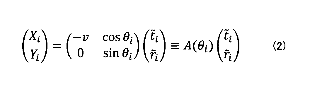
ここで、センサ端末dmの測定値群(センシングデータ群){qj}j={(tm j,rm j)}jと、センサ端末dnの測定値群(センシングデータ群){pk}k={(tn k,rn k)}kが得られているとする(現実的にはセンサ端末dは、連続時間でセンシングできず、測定値(センシングデータ)は離散化された有限個の点となる。添え字j、kは、その測定値を区別するためのインデックスである。)。 Here, the measured value group (sensing data group) of the sensor terminal dm {q j } j = {(t m j , r m j )} j and the measured value group (sensing data group) of the sensor terminal dn {p k } k = {(t n k , r n k )} k is obtained (actually, the sensor terminal d cannot perform sensing in continuous time, and the measured value (sensing data) is discretized There are a finite number of points, and the subscripts j and k are indices for distinguishing the measurements).
図7は、非剛体変換ICPアルゴリズムの処理手順の一例を説明するためのフローチャートである。 FIG. 7 is a flowchart for explaining an example of the processing procedure of the non-rigid transformation ICP algorithm.
ステップS201において、推定部12は、2つのセンサ端末dm、センサ端末dnのそれぞれのセンシング方向について、適当な初期値(θm,θn)を定める。
In step S201, the
続いて、推定部12は、(θm,θn)を用いてセンサ端末dnの各測定値pkをR(θm,θn)pkで変換(非剛体変換)する(S202)。ここで、R(θm,θn)≡A(θm)-1An(θn)である。これにより、センサ端末dnの各測定値(センシングデータ)がセンサ端末dmの測定値空間に写像されたことになる。
Subsequently, the estimating
続いて、推定部12は、センサ端末dmの測定値群{qj}jの中から各R(θm,θn)pkとの所定の距離が最も小さい測定値(これをqj(k))と書くことにする)を特定する(S203)。所定の距離の定義としては、例えば、(速度vを用いて次元を合わせた上での)ユークリッド距離d((t,r),(t',r'))≡√((vt-vt')n+(r-r')n)などを用いればよい。
Subsequently, the estimating
続いて、推定部12は、誤差関数1/M(Σkd(R(θm,θn)pk,qj(k))n)(Mはセンサ端末dnの測定値群のデータ数)を確率勾配法などの任意の最適化手法でθm、θnに関し最小化する(S204)。但し、誤差関数を最小化するためθm、θnを動かす際、ステップS203で定めたpkとqj(k)の対応関係は保ったままとする。
Subsequently, the
続いて、推定部12は、現在のループで得られた誤差(今回の誤差)1/M(Σkd(R(θm,θn)pk,qj(k))n)の値と、一回前のループで得られた誤差(前回の誤差)との差が閾値β以下であるか否かを判定する(S205)。当該差が閾値βより大きい場合(S205でNo)、推定部12は、最小化手続きで得られた(更新された)(θm,θn)を用いて、ステップS202~S204を繰り返す。
Subsequently, the estimating
一方、今回の誤差と前回の誤差との差が閾値β以下である場合(S205でYes)、推定部12は、その時点の(θm,θn)を本アルゴリズムによる推定値(θ^m,θ^n)として出力する(S206)。
On the other hand, if the difference between the current error and the previous error is equal to or less than the threshold value β (Yes in S205), the estimating
このように、本アルゴリズムでは、一方のセンサ端末dの複数のセンシングデータを非剛体変換し、非剛体変換後のセンシングデータ群と、他方のセンサ端末dのセンシングデータ間の距離を最小化する処理を逐次的に繰り返していくことで、これら2つのセンサ端末dのセンシング方向が推定される。 Thus, in this algorithm, a plurality of sensing data of one sensor terminal d are subjected to non-rigid transformation, and the distance between the sensing data group after non-rigid transformation and the sensing data of the other sensor terminal d is minimized. are sequentially repeated, the sensing directions of these two sensor terminals d are estimated.
本アルゴリズムは、非特許文献1におけるθ推定手法と異なり、センシングデータr(t)の高階微分の計算を必要とせず、後述の数値例が示すように、r(t)にノイズが乗る場合でも高い推定精度を維持することができる。
Unlike the θ estimation method in
なお、「P.J. Besl, N.D. McKay, "A method for registration of 3D shapes," IEEE Trans. Pattern Analysis and Machine Intelligence vol. 14, no. 2, 1992.」で提唱され、広く用いられているICPアルゴリズムは、二つの点群(上記で言う{qj}j、{pk}kに相当するもの)を近づけるための変換(上記で言うR(θ1,θ2)に相当する変換)として剛体変換(回転と平行移動)を考えている。本アルゴリズムにおけるR(θ1,θ2)は剛体変換ではないため、非剛体変換ICPアルゴリズムと呼んでいる。 The widely used ICP algorithm proposed in "PJ Besl, ND McKay, "A method for registration of 3D shapes," IEEE Trans. Pattern Analysis and Machine Intelligence vol. 14, no. 2, 1992." , as a transformation (corresponding to R(θ 1 , θ 2 ) mentioned above) for bringing two point groups (corresponding to {q j } j , {p k } k mentioned above) closer together, a rigid transformation (Rotation and translation) are considered. Since R(θ 1 , θ 2 ) in this algorithm is not a rigid transformation, it is called a non-rigid transformation ICP algorithm.
非剛体変換ICPアルゴリズの収束性(ループを繰り返すことで誤差が極小値に収束し、アルゴリズムが停止すること)は、通常のICPアルゴリズムと同様の証明で保証されている。 The convergence of the non-rigid transformation ICP algorithm (that the error converges to a local minimum value by repeating the loop and the algorithm stops) is guaranteed by proof similar to that of the normal ICP algorithm.
なお、ステップS204において、全ての測定値群を用いるのではなく、d(R(θ1,θ2)pk,qj(k))2が、或る一定値以上離れたkに関しては、Σkの中に含めないこととしてもよい。この場合、MはΣkの中に含まれたkの個数となる。 In addition, in step S204, instead of using all the measured value groups, d(R(θ 1 , θ 2 ) p k , q j(k) ) 2 is separated by a certain value or more. It may not be included in Σk . In this case, M is the number of k included in Σk.
また、通常のICPアルゴリズムでは様々な変種(例えば「上記ステップS203にあたるR(θ1,θ2)pkとqj(k)を対応付ける方法として、点間の距離を用いるのではなく垂直距離(点R(θ1,θ2)pkから点群{qk}kがなす接線へ下ろした垂線の距離)を用いる」、「ステップS204での誤差関数として、kごとに異なる重みをつけたものを用いる」など)が考えられている(「S. Rusinkiewicz and M. Levoy, "Efficient variants of the ICP algorithm," in Proc. of 3DIM 2001, 2001.」)が、同様な変種が本アルゴリズムに適用されてもよい。 In addition, in the normal ICP algorithm, various variants (for example, as a method of associating R(θ 1 , θ 2 )p k and q j(k) corresponding to step S203 above, instead of using the distance between points, the vertical distance ( Use the distance of the perpendicular drawn from the point R (θ 1 , θ 2 ) p k to the tangent line formed by the point group {q k } k )”, “As the error function in step S204, a different weight is assigned to each k ("S. Rusinkiewicz and M. Levoy, "Efficient variants of the ICP algorithm," in Proc. of 3DIM 2001, 2001."). may be applied.
続いて、実際に本実施の形態を用いて、楕円形の対象物を用いた数値シミュレーションを実施した結果について説明する。 Next, the results of numerical simulation using an elliptical object using the present embodiment will be described.
物体の速度v=1は既知とし、2つのセンサ端末dの位置、方向を表1のように与えた。 The velocity v=1 of the object is known, and the positions and directions of the two sensor terminals d are given as shown in Table 1.

対象物Tが破線の長方形の領域(監視対象領域)を脱したら計測終了とする。このような設定で得られたセンシングデータ{ri(t)}i(i=1,2)に、平均0、標準偏差10-7、10-6、10-5、10-4、10-3、10-2、10-1、2×10⁻¹、5×10⁻¹のノイズを含めたデータを準備した。各ケースに対し、非特許文献1と本実施の形態の「非剛体変換ICPアルゴリズム」のそれぞれの方法でθ1、θ2の推定を行った。
When the target object T leaves the rectangular area (monitoring target area) indicated by broken lines, the measurement is terminated. Sensing data {r i (t)} i (i=1, 2) obtained with such settings have an average of 0, standard deviations of 10 −7 , 10 −6 , 10 −5 , 10 −4 , 10 − Data including 3 , 10 −2 , 10 −1 , 2×10 −1 and 5×10 −1 noise were prepared. For each case, θ 1 and θ 2 were estimated by the methods of
図9は、シミュレーションの結果を示す図である。図9において、横軸は、ノイズの標準偏差を示し、縦軸はセンシング方向(θ)を示す。また、◆のプロットは、本実施の形態(非剛体変換ICPアルゴリズム)で求めたθ1を示し、□のプロットは、本実施の形態(非剛体変換ICPアルゴリズム)で求めたθ2を示す。一方、△のプロットは、非特許文献1の方法(従来技術)で求めたθ1を示し、●のプロットは、非特許文献1の方法(従来技術)で求めたθ2を示す。更に、破線は、真の(ノイズの無い)θ1を示し、一点鎖線は、真の(ノイズの無い)θ2を示す。 FIG. 9 is a diagram showing simulation results. In FIG. 9, the horizontal axis indicates the standard deviation of noise, and the vertical axis indicates the sensing direction (θ). A plot of ♦ indicates θ 1 obtained by the present embodiment (non-rigid transformation ICP algorithm), and a plot of □ indicates θ 2 obtained by this embodiment (non-rigid transformation ICP algorithm). On the other hand, the plot of Δ indicates θ 1 obtained by the method of Non-Patent Document 1 (prior art), and the plot of ● indicates θ 2 obtained by the method of Non-Patent Document 1 (prior art). Furthermore, the dashed line indicates the true (noiseless) θ 1 and the dash-dotted line indicates the true (noiseless) θ 2 .
図9によれば、ノイズが10-4以下であれば、どちらの方法でも最大で0.3程度のずれでθ1、θ2を求めることができている。しかし、ノイズが10-4より大きくなると、非特許文献1の方法では、θ1、θ2を推定すること自体ができなかったため、図9内に結果はプロットできなかった。一方で、本実施の形態の「非剛体変換ICPアルゴリズム」を用いた場合は、依然として精度よくθ1、θ2が求められていることがわかる。この結果は、本実施の形態を用いればセンシングデータにノイズが含まれている場合であっても、高精度なセンシング方向の推定が可能であることを示すものである。
According to FIG. 9, if the noise is 10 −4 or less, both methods can obtain θ 1 and θ 2 with a maximum deviation of about 0.3. However, when the noise was larger than 10 −4 , the method of
上述したように、本実施の形態によれば、監視対象領域内を移動する対象物Tに対するセンサ端末dのセンシングデータを集積し解析することで、センシングデータにノイズが含まれている場合であっても、高精度にセンシング方向を推定することが可能となる。すなわち、従来技術と異なり高階微分の計算が不要であるため、センシング方向の推定についてセンシングデータのノイズに対する耐性を高めることができる。その結果、高精度な物体形状推定、センサ端末dの位置特定、センサ端末dの時刻同期などが可能になる。 As described above, according to the present embodiment, by accumulating and analyzing the sensing data of the sensor terminal d with respect to the object T moving within the monitoring target area, even if the sensing data contains noise, However, it is possible to estimate the sensing direction with high accuracy. That is, unlike the prior art, calculation of higher-order differentials is not required, so that it is possible to increase the resistance to noise in sensing data in estimating the sensing direction. As a result, highly accurate object shape estimation, position identification of the sensor terminal d, time synchronization of the sensor terminal d, and the like become possible.
以上、本発明の実施の形態について詳述したが、本発明は斯かる特定の実施形態に限定されるものではなく、特許請求の範囲に記載された本発明の要旨の範囲内において、種々の変形・変更が可能である。 Although the embodiments of the present invention have been described in detail above, the present invention is not limited to such specific embodiments, and various modifications can be made within the scope of the gist of the present invention described in the claims. Transformation and change are possible.
10 センシング方向推定装置
11 受信部
12 推定部
13 データ記憶部
20 ユーザ端末
100 ドライブ装置
101 記録媒体
102 補助記憶装置
103 メモリ装置
104 CPU
105 インタフェース装置
B バス
d センサ端末
10 sensing
105 interface device B bus d sensor terminal
Claims (5)
前記推定部は、前記複数のセンサ端末のうちの第1のセンサ端末と他の各センサ端末との組ごとに、前記第1のセンサ端末との組に係る第2のセンサ端末の測定値群を非剛体変換し、非剛体変換後の測定値群と、前記第1のセンサ端末の測定値との距離を最小化する処理を繰り返すことで、前記第1のセンサ端末及び前記第2のセンサ端末それぞれのセンシング方向の推定値を計算する、
ことを特徴とするセンシング方向推定装置。 an estimating unit that calculates an estimate of the sensing direction of each sensor terminal based on a plurality of measurements of the distance between a moving object and the sensor terminal, measured by each of the sensor terminals;
For each set of a first sensor terminal and each of the other sensor terminals among the plurality of sensor terminals, the estimation unit measures a group of measured values of a second sensor terminal related to the set with the first sensor terminal. By repeating the process of non-rigid transformation and minimizing the distance between the measured value group after non-rigid transformation and the measured value of the first sensor terminal, the first sensor terminal and the second sensor Compute an estimate of the sensing direction for each terminal,
A sensing direction estimation device characterized by:
ことを特徴とする請求項1記載のセンシング方向推定装置。 The estimating unit repeats the process for a group of sensor terminals in which the estimated value is not within a threshold with respect to the estimated value of the first sensor terminal among the plurality of sensor terminals, calculating an estimate of the sensing direction of each sensor terminal of the group of sensor terminals;
The sensing direction estimating device according to claim 1, characterized in that:
前記推定手順は、前記複数のセンサ端末のうちの第1のセンサ端末と他の各センサ端末との組ごとに、前記第1のセンサ端末との組に係る第2のセンサ端末の測定値群を非剛体変換し、非剛体変換後の測定値群と、前記第1のセンサ端末の測定値との距離を最小化する処理を繰り返すことで、前記第1のセンサ端末及び前記第2のセンサ端末それぞれのセンシング方向の推定値を計算する、
ことを特徴とするセンシング方向推定方法。 A computer performs an estimation procedure for calculating an estimate of the sensing direction of each sensor terminal based on a plurality of measurements of the distance between a moving object and the sensor terminal, measured by each of the sensor terminals. death,
The estimation procedure includes, for each set of a first sensor terminal and other sensor terminals among the plurality of sensor terminals, a group of measured values of a second sensor terminal associated with the set of the first sensor terminal. By repeating the process of non-rigid transformation and minimizing the distance between the measured value group after non-rigid transformation and the measured value of the first sensor terminal, the first sensor terminal and the second sensor Compute an estimate of the sensing direction for each terminal,
A sensing direction estimation method characterized by:
ことを特徴とする請求項3記載のセンシング方向推定方法。 In the estimation procedure, for a sensor terminal group in which the estimated value is not within a threshold value of the estimated value of the first sensor terminal among the plurality of sensor terminals, the process is repeated for the sensor terminal group, calculating an estimate of the sensing direction of each sensor terminal of the group of sensor terminals;
4. The sensing direction estimation method according to claim 3, wherein:
Priority Applications (1)
| Application Number | Priority Date | Filing Date | Title |
|---|---|---|---|
| JP2019170144A JP7120548B2 (en) | 2019-09-19 | 2019-09-19 | SENSING DIRECTION ESTIMATION DEVICE, SENSING DIRECTION ESTIMATION METHOD AND PROGRAM |
Applications Claiming Priority (1)
| Application Number | Priority Date | Filing Date | Title |
|---|---|---|---|
| JP2019170144A JP7120548B2 (en) | 2019-09-19 | 2019-09-19 | SENSING DIRECTION ESTIMATION DEVICE, SENSING DIRECTION ESTIMATION METHOD AND PROGRAM |
Publications (2)
| Publication Number | Publication Date |
|---|---|
| JP2021047098A JP2021047098A (en) | 2021-03-25 |
| JP7120548B2 true JP7120548B2 (en) | 2022-08-17 |
Family
ID=74876315
Family Applications (1)
| Application Number | Title | Priority Date | Filing Date |
|---|---|---|---|
| JP2019170144A Active JP7120548B2 (en) | 2019-09-19 | 2019-09-19 | SENSING DIRECTION ESTIMATION DEVICE, SENSING DIRECTION ESTIMATION METHOD AND PROGRAM |
Country Status (1)
| Country | Link |
|---|---|
| JP (1) | JP7120548B2 (en) |
Cited By (1)
| Publication number | Priority date | Publication date | Assignee | Title |
|---|---|---|---|---|
| JP3064858B2 (en) | 1995-03-30 | 2000-07-12 | 株式会社押野電気製作所 | Colored cap for small light bulb |
Citations (7)
| Publication number | Priority date | Publication date | Assignee | Title |
|---|---|---|---|---|
| US20050105804A1 (en) | 2003-11-05 | 2005-05-19 | Francos Joseph M. | Parametric estimation of multi-dimensional homeomorphic transformations |
| JP4256342B2 (en) | 2002-05-30 | 2009-04-22 | ヴィズイクス・インコーポレーテッド | System for superimposing first eye image and second eye image |
| JP5300797B2 (en) | 2010-01-12 | 2013-09-25 | 日本電信電話株式会社 | Shape estimation system, angle estimation method, and object number estimation method |
| JP6484577B2 (en) | 2016-03-03 | 2019-03-13 | 日本電信電話株式会社 | Shape estimation apparatus, shape estimation method, and program |
| JP6713953B2 (en) | 2017-06-15 | 2020-06-24 | 日本電信電話株式会社 | Shape estimating device, shape estimating method and program |
| JP6835679B2 (en) | 2017-07-12 | 2021-02-24 | 日本電信電話株式会社 | Shape estimation device, shape estimation method and program |
| JP6888559B2 (en) | 2018-01-24 | 2021-06-16 | 日本電信電話株式会社 | Shape estimation device, shape estimation method and program |
Family Cites Families (2)
| Publication number | Priority date | Publication date | Assignee | Title |
|---|---|---|---|---|
| JP7105447B2 (en) * | 2018-11-20 | 2022-07-25 | 日本電信電話株式会社 | Shape estimation device, shape estimation method and program |
| JP7105448B2 (en) * | 2018-11-20 | 2022-07-25 | 日本電信電話株式会社 | Shape estimation device, shape estimation method and program |
-
2019
- 2019-09-19 JP JP2019170144A patent/JP7120548B2/en active Active
Patent Citations (7)
| Publication number | Priority date | Publication date | Assignee | Title |
|---|---|---|---|---|
| JP4256342B2 (en) | 2002-05-30 | 2009-04-22 | ヴィズイクス・インコーポレーテッド | System for superimposing first eye image and second eye image |
| US20050105804A1 (en) | 2003-11-05 | 2005-05-19 | Francos Joseph M. | Parametric estimation of multi-dimensional homeomorphic transformations |
| JP5300797B2 (en) | 2010-01-12 | 2013-09-25 | 日本電信電話株式会社 | Shape estimation system, angle estimation method, and object number estimation method |
| JP6484577B2 (en) | 2016-03-03 | 2019-03-13 | 日本電信電話株式会社 | Shape estimation apparatus, shape estimation method, and program |
| JP6713953B2 (en) | 2017-06-15 | 2020-06-24 | 日本電信電話株式会社 | Shape estimating device, shape estimating method and program |
| JP6835679B2 (en) | 2017-07-12 | 2021-02-24 | 日本電信電話株式会社 | Shape estimation device, shape estimation method and program |
| JP6888559B2 (en) | 2018-01-24 | 2021-06-16 | 日本電信電話株式会社 | Shape estimation device, shape estimation method and program |
Non-Patent Citations (1)
| Title |
|---|
| 金井 廉 Ren Kanai,第77回(平成27年)全国大会講演論文集(2) 人工知能と認知科学 |
Cited By (1)
| Publication number | Priority date | Publication date | Assignee | Title |
|---|---|---|---|---|
| JP3064858B2 (en) | 1995-03-30 | 2000-07-12 | 株式会社押野電気製作所 | Colored cap for small light bulb |
Also Published As
| Publication number | Publication date |
|---|---|
| JP2021047098A (en) | 2021-03-25 |
Similar Documents
| Publication | Publication Date | Title |
|---|---|---|
| CN107371129B (en) | TDOA (time difference of arrival) positioning method based on indoor positioning of altitude-assisted correction | |
| CN108896047B (en) | Distributed sensor network collaborative fusion and sensor location correction method | |
| CN109195110B (en) | Indoor localization method based on hierarchical clustering technology and online extreme learning machine | |
| CN106709943B (en) | A kind of point cloud registration method based on optimal transmission | |
| CN106599368B (en) | FastSLAM method based on improved particle proposal distribution and adaptive particle resampling | |
| CN104869541B (en) | A kind of indoor positioning method for tracing | |
| EP2098882A2 (en) | Location measurement method based on predictive filter | |
| JP6349418B2 (en) | Object positioning by high-precision monocular movement | |
| CN105866735B (en) | The reaching time-difference iteration localization method of amendment cost function based on MDS models | |
| CN108645415A (en) | A method for predicting ship track | |
| JP2012128661A (en) | Information processor, information processing method and program | |
| WO2014106363A1 (en) | Mobile device positioning system and method | |
| CN107743296A (en) | A Segmented Positioning Method for RSSI Area Based on Compressed Sensing | |
| CN111765882A (en) | Laser radar positioning method and related device thereof | |
| CN111854732B (en) | An indoor fingerprint positioning method based on data fusion and width learning | |
| CN109388856A (en) | A kind of temperature field prediction method based on sensing data fusion | |
| CN111145243A (en) | Parameterized geometric ellipse accurate fitting method | |
| KR20200064421A (en) | Automated system for detecting 3D pipeline | |
| CN113168729A (en) | A 3D shape matching method and device based on local reference coordinate system | |
| CN105765562A (en) | Method and device for determining a data-based functional model | |
| CN116437290A (en) | A Model Fusion Method Based on CSI Fingerprint Location | |
| JP5928010B2 (en) | Road marking detection apparatus and program | |
| JP7120548B2 (en) | SENSING DIRECTION ESTIMATION DEVICE, SENSING DIRECTION ESTIMATION METHOD AND PROGRAM | |
| JP2014106725A (en) | Point group analyzer, point group analysis method and point group analysis program | |
| CN104050686B (en) | A Dense Space Target Tracking Method |
Legal Events
| Date | Code | Title | Description |
|---|---|---|---|
| RD01 | Notification of change of attorney |
Free format text: JAPANESE INTERMEDIATE CODE: A7426 Effective date: 20190924 |
|
| A521 | Request for written amendment filed |
Free format text: JAPANESE INTERMEDIATE CODE: A821 Effective date: 20190924 |
|
| A621 | Written request for application examination |
Free format text: JAPANESE INTERMEDIATE CODE: A621 Effective date: 20210901 |
|
| TRDD | Decision of grant or rejection written | ||
| A01 | Written decision to grant a patent or to grant a registration (utility model) |
Free format text: JAPANESE INTERMEDIATE CODE: A01 Effective date: 20220719 |
|
| A61 | First payment of annual fees (during grant procedure) |
Free format text: JAPANESE INTERMEDIATE CODE: A61 Effective date: 20220726 |
|
| R150 | Certificate of patent or registration of utility model |
Ref document number: 7120548 Country of ref document: JP Free format text: JAPANESE INTERMEDIATE CODE: R150 |
|
| R250 | Receipt of annual fees |
Free format text: JAPANESE INTERMEDIATE CODE: R250 |
|
| S533 | Written request for registration of change of name |
Free format text: JAPANESE INTERMEDIATE CODE: R313533 |
|
| R350 | Written notification of registration of transfer |
Free format text: JAPANESE INTERMEDIATE CODE: R350 |