JP7118084B2 - Wearable display device using multiple visual field - Google Patents
Wearable display device using multiple visual field Download PDFInfo
- Publication number
- JP7118084B2 JP7118084B2 JP2019551593A JP2019551593A JP7118084B2 JP 7118084 B2 JP7118084 B2 JP 7118084B2 JP 2019551593 A JP2019551593 A JP 2019551593A JP 2019551593 A JP2019551593 A JP 2019551593A JP 7118084 B2 JP7118084 B2 JP 7118084B2
- Authority
- JP
- Japan
- Prior art keywords
- image
- light
- projector
- optical path
- display device
- Prior art date
- Legal status (The legal status is an assumption and is not a legal conclusion. Google has not performed a legal analysis and makes no representation as to the accuracy of the status listed.)
- Active
Links
Images


Classifications
-
- G—PHYSICS
- G02—OPTICS
- G02B—OPTICAL ELEMENTS, SYSTEMS OR APPARATUS
- G02B6/00—Light guides; Structural details of arrangements comprising light guides and other optical elements, e.g. couplings
-
- G—PHYSICS
- G02—OPTICS
- G02B—OPTICAL ELEMENTS, SYSTEMS OR APPARATUS
- G02B27/00—Optical systems or apparatus not provided for by any of the groups G02B1/00 - G02B26/00, G02B30/00
- G02B27/02—Viewing or reading apparatus
- G02B27/022—Viewing apparatus
- G02B27/024—Viewing apparatus comprising a light source, e.g. for viewing photographic slides, X-ray transparancies
- G02B27/026—Viewing apparatus comprising a light source, e.g. for viewing photographic slides, X-ray transparancies and a display device, e.g. CRT, LCD, for adding markings or signs or to enhance the contrast of the viewed object
-
- G—PHYSICS
- G02—OPTICS
- G02B—OPTICAL ELEMENTS, SYSTEMS OR APPARATUS
- G02B27/00—Optical systems or apparatus not provided for by any of the groups G02B1/00 - G02B26/00, G02B30/00
- G02B27/0081—Optical systems or apparatus not provided for by any of the groups G02B1/00 - G02B26/00, G02B30/00 with means for altering, e.g. enlarging, the entrance or exit pupil
-
- G—PHYSICS
- G02—OPTICS
- G02B—OPTICAL ELEMENTS, SYSTEMS OR APPARATUS
- G02B27/00—Optical systems or apparatus not provided for by any of the groups G02B1/00 - G02B26/00, G02B30/00
- G02B27/01—Head-up displays
- G02B27/017—Head mounted
- G02B27/0172—Head mounted characterised by optical features
-
- G—PHYSICS
- G02—OPTICS
- G02B—OPTICAL ELEMENTS, SYSTEMS OR APPARATUS
- G02B27/00—Optical systems or apparatus not provided for by any of the groups G02B1/00 - G02B26/00, G02B30/00
- G02B27/18—Optical systems or apparatus not provided for by any of the groups G02B1/00 - G02B26/00, G02B30/00 for optical projection, e.g. combination of mirror and condenser and objective
-
- G—PHYSICS
- G02—OPTICS
- G02B—OPTICAL ELEMENTS, SYSTEMS OR APPARATUS
- G02B27/00—Optical systems or apparatus not provided for by any of the groups G02B1/00 - G02B26/00, G02B30/00
- G02B27/42—Diffraction optics, i.e. systems including a diffractive element being designed for providing a diffractive effect
- G02B27/4272—Diffraction optics, i.e. systems including a diffractive element being designed for providing a diffractive effect having plural diffractive elements positioned sequentially along the optical path
-
- G—PHYSICS
- G02—OPTICS
- G02B—OPTICAL ELEMENTS, SYSTEMS OR APPARATUS
- G02B27/00—Optical systems or apparatus not provided for by any of the groups G02B1/00 - G02B26/00, G02B30/00
- G02B27/01—Head-up displays
- G02B27/0101—Head-up displays characterised by optical features
- G02B2027/0123—Head-up displays characterised by optical features comprising devices increasing the field of view
-
- G—PHYSICS
- G02—OPTICS
- G02B—OPTICAL ELEMENTS, SYSTEMS OR APPARATUS
- G02B6/00—Light guides; Structural details of arrangements comprising light guides and other optical elements, e.g. couplings
- G02B6/0001—Light guides; Structural details of arrangements comprising light guides and other optical elements, e.g. couplings specially adapted for lighting devices or systems
- G02B6/0011—Light guides; Structural details of arrangements comprising light guides and other optical elements, e.g. couplings specially adapted for lighting devices or systems the light guides being planar or of plate-like form
- G02B6/0075—Arrangements of multiple light guides
- G02B6/0078—Side-by-side arrangements, e.g. for large area displays
-
- G—PHYSICS
- G06—COMPUTING OR CALCULATING; COUNTING
- G06T—IMAGE DATA PROCESSING OR GENERATION, IN GENERAL
- G06T19/00—Manipulating 3D models or images for computer graphics
- G06T19/006—Mixed reality
Landscapes
- Physics & Mathematics (AREA)
- General Physics & Mathematics (AREA)
- Optics & Photonics (AREA)
- Engineering & Computer Science (AREA)
- Computer Graphics (AREA)
- Computer Hardware Design (AREA)
- General Engineering & Computer Science (AREA)
- Software Systems (AREA)
- Theoretical Computer Science (AREA)
- Diffracting Gratings Or Hologram Optical Elements (AREA)
- Controls And Circuits For Display Device (AREA)
Description
(関連出願の相互参照)
本願は、2017年3月22日に出願され”Wearable Display Device Utilizing A Composite Field Of View”と題された米国仮特許出願第62/475,087号に対する優先権を主張するものである。
(Cross reference to related applications)
This application claims priority to U.S. Provisional Patent Application No. 62/475,087, filed March 22, 2017 and entitled "Wearable Display Device Utilizing A Composite Field Of View."
ウェアラブルディスプレイデバイスは、多くの場合、略均一な方向においてユーザの眼に画像フィールドを投影する接眼レンズを含む。ウェアラブルディスプレイデバイスの製造において本実践が継続されている1つの理由は、回折導波管の分離光学系が、概して、1つの方向に配向されている分離光学系によって放出される画像フィールドのために限定され、ディスプレイ用途において限定された視野をもたらすためである。このように画像フィールドを分離することは、単純な設計を促進するが、ユーザの眼へのこれらの接眼レンズの近接近は、多くの場合、ウェアラブルディスプレイデバイスによって表示可能な視野のサイズを限定する。ディスプレイのピクセルの有効角度を増加させること等のあるディスプレイ変形例が、ある程度これらの問題を改善することができるが、これらの変更は、多くの場合、付加的電力の必要性をもたらし、あるディスプレイ設計のためには技術的にも適していない場合がある。ウェアラブルデバイスが、概して、バッテリ給電されることを前提として、より高い電力出力は、ウェアラブルデバイスの使用可能動作時間の量を実質的に低減させ得る。 Wearable display devices often include an eyepiece that projects an image field onto the user's eye in a substantially uniform direction. One reason this practice continues in the manufacture of wearable display devices is because of the image field emitted by the separating optics of the diffractive waveguide, which is generally oriented in one direction. This is because it is limited and provides a limited field of view in display applications. Separating the image fields in this way facilitates a simpler design, but the proximity of these eyepieces to the user's eye often limits the size of the field of view that can be displayed by wearable display devices. . While certain display modifications, such as increasing the effective angle of the display's pixels, can ameliorate these problems to some extent, these modifications often result in additional power requirements and some display It may also not be technically suitable for the design. Given that wearable devices are generally battery powered, a higher power output can substantially reduce the amount of usable operating time of the wearable device.
本開示は、概して、ウェアラブルディスプレイデバイスを使用するとき、ユーザの有効視野を拡大するための方法および装置に関する。 FIELD OF THE DISCLOSURE The present disclosure relates generally to methods and apparatus for increasing a user's effective field of view when using a wearable display device.
ウェアラブルデバイスの有効視野は、接眼レンズの各表示領域からの光出力が、概して、ユーザの眼に向かって配向されるように、接眼レンズと関連付けられる異なる表示領域からの光を異なる方向に配向することによって拡大されることができる。このように、ユーザの周辺視野内に位置する表示領域の一部によって放出されている光は、ユーザの眼に到達することができる。いくつかの実施形態では、より多数の表示領域が、有効視野をさらに増加させるために使用されることができる。より多数の表示領域は、各表示領域が1つの方向に配向される画像フィールドを放出することに限定される構成において有用である。例えば、ユーザの視野の遠い周辺領域のみを占有する表示領域は、ユーザの視野の近傍および遠い周辺領域の両方を占有する表示領域よりもユーザの眼に向かって精密に指向され得る。より多い数の表示領域を利用する実施形態はまた、より多数の表示領域をサポートするために、プロジェクタ等のより多数の光源を利用することができる。 The effective field of view of the wearable device directs light from different display areas associated with the eyepiece in different directions such that the light output from each display area of the eyepiece is generally directed towards the user's eye. can be expanded by In this way, light being emitted by a portion of the display area located within the user's peripheral vision can reach the user's eyes. In some embodiments, a larger number of display areas can be used to further increase the effective field of view. A larger number of display areas is useful in configurations where each display area is limited to emitting image fields oriented in one direction. For example, a display area that occupies only the far peripheral area of the user's field of vision may be directed more precisely toward the user's eye than a display area that occupies both near and far peripheral areas of the user's field of vision. Embodiments utilizing a greater number of display areas may also utilize a greater number of light sources, such as projectors, to support a greater number of display areas.
プロジェクタと、プロジェクタから受け取られた光を第1の角度においてユーザに向かって再指向するように構成される第1の入力領域を有する、第1の光学経路と、第1の入力領域に隣接し、プロジェクタから受け取られた光を第1の角度とは異なる第2の角度においてユーザに向かって再指向するように構成される第2の入力領域を有する、第2の光学経路とを画定する、光学要素を備える、導波管システムとを含む、ウェアラブルディスプレイデバイスが、開示される。 a projector; a first optical path having a first input area configured to redirect light received from the projector toward a user at a first angle; , a second optical path having a second input area configured to redirect light received from the projector toward the user at a second angle different from the first angle; A wearable display device comprising a waveguide system comprising an optical element is disclosed.
プロジェクタと、導波管システムとを含む、別のウェアラブルディスプレイデバイスが、説明される。導波管システムは、プロジェクタから光を受け取るように構成される第1および第2の入力領域を有する、入力結合格子と、第1の入力領域および第2の入力領域のうちの対応するものから受け取られた光を透過するように構成される、第1および第2の直交瞳エキスパンダと、直交瞳エキスパンダのうちの対応するものから光を受け取り、光をユーザに向かって再指向するように構成される、第1および第2の射出瞳エキスパンダとを含む。第2の射出瞳エキスパンダは、第1の射出瞳エキスパンダとは異なる角度において導波管システムからの光を分離するように構成される。 Another wearable display device is described that includes a projector and waveguide system. A waveguide system from an input coupling grating having first and second input areas configured to receive light from the projector and a corresponding one of the first input area and the second input area. First and second orthogonal pupil expanders configured to transmit the received light, and to receive light from corresponding ones of the orthogonal pupil expanders and to redirect the light toward the user. and first and second exit pupil expanders configured to: The second exit pupil expander is configured to separate light from the waveguide system at a different angle than the first exit pupil expander.
プロジェクタと、第1の光学経路と、第1の光学経路とは別個であり、明確に異なる、第2の光学経路とを画定する、光学要素を含む、回折導波管システムとを含む、別のウェアラブルディスプレイデバイスが、説明される。第1および第2の光学経路は、プロジェクタから光を受け取るように構成される。第1の光学経路は、プロジェクタから受け取られた光の第1の部分を第1の角度においてユーザに向かって分離するように構成され、第2の光学経路は、プロジェクタからの光の第2の部分を第1の角度とは異なる第2の角度においてユーザに向かって分離するように構成される。
本明細書は、例えば、以下も提供する。
(項目1)
ウェアラブルディスプレイデバイスであって、
プロジェクタと、
光学要素を備える導波管システムであって、前記光学要素は、
前記プロジェクタから受け取られた光を第1の角度においてユーザに向かって再指向するように構成される第1の入力領域を有する第1の光学経路と、
第2の光学経路であって、前記第2の光学経路は、第2の入力領域を有し、前記第2の入力領域は、前記第1の入力領域に隣接し、前記プロジェクタから受け取られた光を前記第1の角度とは異なる第2の角度において前記ユーザに向かって再指向するように構成される、第2の光学経路と
を画定する、導波管システムと
を備える、ウェアラブルディスプレイデバイス。
(項目2)
前記第1の入力領域は、入力結合格子の第1の側上に位置し、前記第2の入力領域は、前記入力結合格子の第2の側上に位置する、項目1に記載のウェアラブルディスプレイデバイス。
(項目3)
前記入力結合格子は、前記第1の入力領域において受け取られた前記光を第1の直交瞳エキスパンダに再指向し、前記第2の入力領域において受け取られた前記光を前記第1の直交瞳エキスパンダとは別個であり、明確に異なる第2の直交瞳エキスパンダに再指向する、項目2に記載のウェアラブルディスプレイデバイス。
(項目4)
前記プロジェクタは、光を前記第1の入力領域および前記第2の入力領域の両方の中に並行して指向するように構成される、項目1に記載のウェアラブルディスプレイデバイス。
(項目5)
前記導波管システムは、入力結合格子と、第1および第2の直交瞳エキスパンダと、第1および第2の射出瞳エキスパンダとを備える、項目1に記載のウェアラブルディスプレイデバイス。
(項目6)
前記第1の射出瞳エキスパンダは、前記第1の光学経路の一部を形成し、前記第2の射出瞳エキスパンダは、前記第2の光学経路の一部を形成し、前記第1の射出瞳エキスパンダから側方にオフセットされる、項目5に記載のウェアラブルディスプレイデバイス。
(項目7)
前記光学要素は、回折光学要素を備える、項目1に記載のウェアラブルディスプレイデバイス。
(項目8)
ウェアラブルディスプレイデバイスであって、
プロジェクタと、
導波管システムであって、前記導波管システムは、
前記プロジェクタから光を受け取るように構成される第1および第2の入力領域と、
前記第1の入力領域および前記第2の入力領域のうちの対応するものから受け取られた光を透過するように構成される第1および第2の直交瞳エキスパンダと、
前記直交瞳エキスパンダのうちの対応するものから光を受け取り、前記光をユーザに向かって再指向するように構成される第1および第2の射出瞳エキスパンダと
を備える、導波管システムと
を備え、
前記第2の射出瞳エキスパンダは、前記第1の射出瞳エキスパンダとは異なる角度において前記導波管システムからの光を分離するように構成される、ウェアラブルディスプレイデバイス。
(項目9)
前記第1および第2の入力領域は、入力結合格子の隣接する部分である、項目8に記載のウェアラブルディスプレイデバイス。
(項目10)
前記第1の射出瞳エキスパンダは、前記光を第1の角度において前記ユーザの眼のうちの第1のものに向かって再指向するように構成され、前記第2の射出瞳エキスパンダは、前記光を前記第1の角度とは異なる第2の角度において前記ユーザの眼のうちの第2のものに向かって再指向するように構成される、項目8に記載のウェアラブルディスプレイデバイス。
(項目11)
前記第1の入力領域は、前記第1の入力領域によって受け取られた少なくとも一部の光が前記第2の直交瞳エキスパンダによって透過されることを防止する光ブロックによって、前記第2の入力領域から分離される、項目8に記載のウェアラブルディスプレイデバイス。
(項目12)
前記プロジェクタは、第1のプロジェクタであり、前記ウェアラブルディスプレイデバイスはさらに、第2のプロジェクタを備える、項目8に記載のウェアラブルディスプレイデバイス。
(項目13)
前記導波管システムは、前記第1のプロジェクタおよび前記第2のプロジェクタの両方から放出された前記光の少なくとも一部を前記ウェアラブルディスプレイデバイスのユーザの片方の眼に送達するように構成される、項目12に記載のウェアラブルディスプレイデバイス。
(項目14)
ウェアラブルディスプレイデバイスであって、
プロジェクタと、
光学要素を備える回折導波管システムであって、前記光学要素は、
第1の光学経路と、
前記第1の光学経路とは別個であり、明確に異なる第2の光学経路であって、前記第1および第2の光学経路は、前記プロジェクタから光を受け取るように構成され、前記第1の光学経路は、前記プロジェクタからの前記光の第1の部分を第1の角度においてユーザに向かって分離するように構成され、前記第2の光学経路は、前記プロジェクタからの前記光の第2の部分を前記第1の角度とは異なる第2の角度において前記ユーザに向かって分離するように構成される、第2の光学経路と
を画定する、回折導波管システムと
を備える、ウェアラブルディスプレイデバイス。
(項目15)
前記回折導波管システムを支持するように定寸される開口部を画定するフレームをさらに備え、前記フレームは、前記ユーザの耳に係合するように構成されるテンプルを備える、項目14に記載のウェアラブルディスプレイデバイス。
(項目16)
前記プロジェクタは、前記テンプルに結合され、前記ユーザの眼から離れるように光を指向するように構成される、項目15に記載のウェアラブルディスプレイデバイス。
(項目17)
前記第1の光学経路は、第1の入力領域を備え、前記第2の光学経路は、前記第1の入力領域に隣接する第2の入力領域を備え、前記第1および第2の入力領域は、前記プロジェクタから前記光を受け取るように構成される、項目14に記載のウェアラブルディスプレイデバイス。
(項目18)
前記回折導波管システムはさらに、第3および第4の光学経路を備え、前記第3および第4の光学経路は、前記プロジェクタから光を受け取るように構成され、前記光の個別の第3および第4の部分を前記ユーザの眼に向かって分離する、項目14に記載のウェアラブルディスプレイデバイス。
(項目19)
前記プロジェクタは、第1のプロジェクタであり、前記ウェアラブルディスプレイデバイスはさらに、前記回折導波管システムの第3および第4の光学経路の中に光を投影するように構成される第2のプロジェクタを備える、項目14に記載のウェアラブルディスプレイデバイス。
(項目20)
前記第1の光学経路は、第1の入力結合格子と、第1の直交瞳エキスパンダと、第1の射出瞳エキスパンダとを備え、前記第2の光学経路は、前記第1の入力結合格子に隣接する第2の入力結合格子と、第2の直交瞳エキスパンダと、第2の射出瞳エキスパンダとを備える、項目14に記載のウェアラブルディスプレイデバイス。
a projector; a first optical path; and a diffractive waveguide system that includes optical elements that define a second optical path that is separate and distinct from the first optical path. wearable display device is described. The first and second optical paths are configured to receive light from the projector. A first optical path is configured to separate a first portion of light received from the projector toward a user at a first angle, and a second optical path is configured to separate a second portion of light from the projector. The portions are configured to separate toward the user at a second angle that is different from the first angle.
This specification also provides, for example:
(Item 1)
A wearable display device,
a projector;
A waveguide system comprising an optical element, said optical element comprising:
a first optical path having a first input area configured to redirect light received from the projector toward a user at a first angle;
a second optical path, said second optical path having a second input area, said second input area adjacent said first input area and received from said projector a second optical path configured to redirect light toward the user at a second angle different from the first angle;
a waveguide system and
A wearable display device comprising:
(Item 2)
2. The wearable display of
(Item 3)
The incoupling grating redirects the light received at the first input region to a first orthogonal pupil expander and directs the light received at the second input region to the first orthogonal pupil expander. 3. The wearable display device of item 2, redirecting to a second orthogonal pupil expander that is separate and distinct from the expander.
(Item 4)
2. The wearable display device of
(Item 5)
2. The wearable display device of
(Item 6)
The first exit pupil expander forms part of the first optical path, the second exit pupil expander forms part of the second optical path, and the first exit pupil expander forms part of the second optical path. 6. The wearable display device of item 5, laterally offset from the exit pupil expander.
(Item 7)
2. The wearable display device of
(Item 8)
A wearable display device,
a projector;
A waveguide system, said waveguide system comprising:
first and second input areas configured to receive light from the projector;
first and second orthogonal pupil expanders configured to transmit light received from corresponding ones of the first input area and the second input area;
first and second exit pupil expanders configured to receive light from corresponding ones of said quadrature pupil expanders and redirect said light towards a user;
a waveguide system comprising
with
The wearable display device, wherein the second exit pupil expander is configured to separate light from the waveguide system at a different angle than the first exit pupil expander.
(Item 9)
9. Wearable display device according to item 8, wherein the first and second input areas are adjacent parts of an input coupling grid.
(Item 10)
The first exit pupil expander is configured to redirect the light toward a first one of the user's eyes at a first angle, and the second exit pupil expander is configured to: 9. Wearable display device according to item 8, configured to redirect the light towards a second one of the user's eyes at a second angle different from the first angle.
(Item 11)
The first input area is defined by a light block that prevents at least some light received by the first input area from being transmitted by the second quadrature pupil expander. 9. The wearable display device of item 8, wherein the wearable display device is separated from.
(Item 12)
9. The wearable display device of item 8, wherein the projector is a first projector and the wearable display device further comprises a second projector.
(Item 13)
wherein the waveguide system is configured to deliver at least a portion of the light emitted from both the first projector and the second projector to one eye of a user of the wearable display device; 13. A wearable display device according to item 12.
(Item 14)
A wearable display device,
a projector;
A diffractive waveguide system comprising an optical element, said optical element comprising:
a first optical path;
a second optical path separate and distinct from said first optical path, said first and second optical paths being configured to receive light from said projector; An optical path is configured to separate a first portion of the light from the projector toward a user at a first angle, and the second optical path separates a second portion of the light from the projector. a second optical path configured to separate portions toward the user at a second angle different from the first angle;
a diffractive waveguide system and
A wearable display device comprising:
(Item 15)
15. Clause 15, further comprising a frame defining an opening dimensioned to support said diffractive waveguide system, said frame comprising temples configured to engage said user's ear. wearable display device.
(Item 16)
16. The wearable display device of item 15, wherein the projector is coupled to the temple and configured to direct light away from the user's eye.
(Item 17)
The first optical path comprises a first input area, the second optical path comprises a second input area adjacent to the first input area, the first and second input areas 15. The wearable display device of item 14, wherein is configured to receive the light from the projector.
(Item 18)
The diffractive waveguide system further comprises third and fourth optical paths, the third and fourth optical paths configured to receive light from the projector and separate third and fourth optical paths of the light. 15. The wearable display device of item 14, separating a fourth portion towards the eye of the user.
(Item 19)
The projector is a first projector, and the wearable display device further includes a second projector configured to project light into third and fourth optical paths of the diffractive waveguide system. 15. The wearable display device of item 14, comprising:
(Item 20)
The first optical path comprises a first incoupling grating, a first orthogonal pupil expander, and a first exit pupil expander, and the second optical path is coupled to the first incoupling. 15. The wearable display device of item 14, comprising a second incoupling grating adjacent to the grating, a second orthogonal pupil expander, and a second exit pupil expander.
本発明の他の側面および利点が、実施例として、説明される実施形態の原理を図示する、付随の図面と併せて検討される、以下の詳細な説明から明白となるであろう。 Other aspects and advantages of the present invention will become apparent from the following detailed description, considered in conjunction with the accompanying drawings, which illustrate, by way of example, the principles of the described embodiments.
本開示は、同様の参照番号が同様の構造要素を指定する、付随の図面と併せて、以下の詳細な説明によって容易に理解されるであろう。 The present disclosure will be readily understood by the following detailed description, taken in conjunction with the accompanying drawings, in which like reference numerals designate like structural elements.
本願による、方法および装置の代表的用途が、本節に説明される。これらの実施例は、文脈を追加し、説明される実施形態の理解を支援するためだけに提供されている。したがって、説明される実施形態は、これらの具体的詳細のうちのいくつかまたは全てを伴わずに実践され得ることが当業者に明白となるであろう。他の事例では、周知のプロセスステップは、説明される実施形態を不必要に不明瞭にすることを回避するために、詳細に説明されていない。他の用途も、可能性として考えられ、したがって、以下の実施例は、限定として捉えられるべきではない。 A representative application of the method and apparatus according to the present application is described in this section. These examples are provided only to add context and aid in understanding the described embodiments. Therefore, it will be apparent to one skilled in the art that the described embodiments may be practiced without some or all of these specific details. In other instances, well known process steps have not been described in detail to avoid unnecessarily obscuring the described embodiments. Other applications are also possible and thus the examples below should not be taken as limiting.
壁掛けディスプレイ等の従来のディスプレイは、多くの場合、複数の異なる角度から視認可能であるように設計される。このように、コンテンツが、そのようなディスプレイの近傍内の複数の異なる場所に位置付けられるユーザに提示され得る。これを遂行するために、ディスプレイの各ピクセル場所は、多くの場合、ディスプレイを視認するユーザが複数の異なる位置からディスプレイの一貫したビューを享受することが可能であるように、これが放出する光を大きい有効角度を横断して拡散するように要求される。残念ながら、大きい有効角度を伴うピクセルを有するディスプレイのために所望の画像輝度を維持することは、概して、小さい有効角度を有するピクセルを伴うディスプレイよりも多くのエネルギーを要求する。大きい有効角度構成は、壁コンセントにプラグ接続された大型定常ディスプレイに関して良好に機能し得るが、本構成は、バッテリ電力に依存するモバイルディスプレイデバイスのために理想的ではない場合がある。 Conventional displays, such as wall-mounted displays, are often designed to be viewable from multiple different angles. In this manner, content may be presented to users positioned at multiple different locations within the vicinity of such a display. To accomplish this, each pixel location in the display often allocates the light it emits so that a user viewing the display can enjoy a consistent view of the display from multiple different positions. Required to diffuse across a large effective angle. Unfortunately, maintaining desired image brightness for displays with pixels with large effective angles generally requires more energy than displays with pixels with small effective angles. While the large effective angle configuration may work well for large stationary displays plugged into a wall outlet, this configuration may not be ideal for mobile display devices that rely on battery power.
一方、本発明の実施形態と関連して本明細書に説明されるもの等のウェアラブルディスプレイデバイスは、その位置が、概して、把握される単一のユーザにコンテンツを提示する役割を果たし得る。この理由から、そのようなウェアラブルディスプレイデバイスは、壁掛けディスプレイおよび広範囲の視認位置を横断して一貫した画像品質を提供することが意図される他のディスプレイデバイスの設計に反映される非効率的な要素のうちのいくつかを含む必要はない。例えば、ピクセル毎の有効角度は、実質的に低減され、光出力は、ユーザの眼の予期される位置と整合されることができる。下記にさらに詳細に説明されるように、これを遂行するための1つの方法は、表示領域が合成画像または画像ストリームを協働的に生成するように、ウェアラブルディスプレイの各接眼レンズを複数の表示領域にセグメント化することである。各表示領域は、次いで、画像または画像ストリームに関連付けられた配向の光の一部をユーザの眼の予期される位置に向かって分離するように構成されることができる。 On the other hand, wearable display devices such as those described herein in connection with embodiments of the present invention may serve to present content to a single user whose position is generally known. For this reason, such wearable display devices are an inefficient factor reflected in the design of wall mounted displays and other display devices intended to provide consistent image quality across a wide range of viewing positions. It is not necessary to include some of the For example, the effective angle per pixel can be substantially reduced and the light output matched with the expected position of the user's eye. As will be described in more detail below, one method for accomplishing this is to connect each eyepiece of the wearable display to multiple views such that the display areas cooperatively produce a composite image or image stream. segmenting into regions. Each display region can then be configured to separate a portion of the oriented light associated with the image or image stream toward the expected position of the user's eye.
いくつかの実施形態では、ウェアラブルディスプレイデバイスは、プロジェクタからの光をウェアラブルデバイスのユーザの眼に指向するように構成される、回折光学要素を含む。回折光学要素によって受け取られた光は、複数の光学経路に分配されることができ、経路のうちの各1つは、個別の表示領域のうちの1つに対応する。光学経路はそれぞれ、投影光を受け取るように構成される入力結合格子、1つ以上の射出瞳エキスパンダに光を分配するように構成される直交瞳エキスパンダ、およびユーザの眼に向かって光を分離するように構成される射出瞳エキスパンダによって画定されることができる。 In some embodiments, the wearable display device includes a diffractive optical element configured to direct light from the projector to the eye of the user of the wearable device. Light received by the diffractive optical element can be distributed into multiple optical paths, each one of which corresponds to one of the discrete display areas. The optical paths each include an input coupling grating configured to receive projection light, a quadrature pupil expander configured to distribute light to one or more exit pupil expanders, and direct light toward the user's eye. It can be defined by an exit pupil expander configured to separate.
いくつかの実施形態では、単一の入力結合格子が、複数の入力領域に細分化されることができ、したがって、入力結合格子によって受け取られた光は、複数の表示領域に分配されることができる。入力結合格子は、複数の方法でプロジェクタから受け取られた光を分割することができる。いくつかの実施形態では、入力結合格子の異なる領域は、ウェアラブルデバイスの異なる表示領域に対応することができる。光遮断要素が、入力結合格子の隣接する領域の間のクロストークを防止するために、入力結合格子内に位置付けられることができる。いくつかの実施形態では、プロジェクタは、特定の光学経路に従って、投影光の特性を変化させるように構成されることができる。例えば、投影光の異なる部分が、異なる偏向を有することができる。いくつかの実施形態では、第1の偏向は、入力結合格子に入射する光が第1の方向に進行することをもたらし、第2の偏向は、入力結合格子に入射する光を第1の方向とは異なる第2の方向に進行させるであろう。偏向感受性入力結合要素(例えば、コレステリック液晶格子)およびそれに光学的に結合される偏向感受性入力結合要素を伴う導波管システムアーキテクチャの実施例が、2018年2月22日に出願された米国特許出願第15/902,927号にさらに詳細に説明されている。少なくともいくつかの実施例では、本明細書に説明されるシステムおよび技法のうちの1つ以上のものは、偏向に基づいて、光を異なる接眼レンズ構成要素に選択的に経路指定するように、そのような偏向感受性入力結合要素および導波管システムアーキテクチャを利用し得るということになる。代替として、プロジェクタは、光の波長を調節し、波長範囲の第1のセット内の光を1つの光学経路を辿って進行させ、波長範囲の第2のセット内の光を別の光学経路を辿って進行させ得る。いくつかの実施形態では、導波管の各光学経路の中に組み込まれた性質は、誤った光学経路に意図せず入射した光が、ユーザに向かって外部結合されることを防止し得る。 In some embodiments, a single incoupling grating can be subdivided into multiple input regions, and thus light received by the incoupling grating can be distributed over multiple display regions. can. The input coupling grating can split the light received from the projector in multiple ways. In some embodiments, different regions of the incoupling grid can correspond to different display regions of the wearable device. Light blocking elements can be positioned within the incoupling grating to prevent crosstalk between adjacent regions of the incoupling grating. In some embodiments, the projector can be configured to change the properties of the projected light according to a particular optical path. For example, different parts of the projection light can have different polarizations. In some embodiments, a first polarization causes light incident on the incoupling grating to travel in a first direction, and a second polarization causes light incident on the incoupling grating to travel in the first direction. will proceed in a second direction different from the Examples of waveguide system architectures with a polarization-sensitive input coupling element (e.g., a cholesteric liquid crystal grating) and a polarization-sensitive input coupling element optically coupled thereto are U.S. patent application filed February 22, 2018 Further details are provided in 15/902,927. In at least some embodiments, one or more of the systems and techniques described herein selectively route light to different eyepiece components based on polarization, It follows that such deflection sensitive input coupling elements and waveguide system architectures can be utilized. Alternatively, the projector modulates the wavelength of the light, directing light within a first set of wavelength ranges down one optical path and light within a second set of wavelength ranges down another optical path. You can follow along and progress. In some embodiments, the embedded nature of waveguides within each optical path may prevent light unintentionally entering the wrong optical path from being coupled out towards the user.
これらおよび他の実施形態は、図1-7を参照して下記に議論されるが、しかしながら、当業者は、これらの図に関して本明細書に与えられる詳細な説明は、解説目的のためだけのものであり、限定として解釈されるべきではないことを容易に理解するであろう。 These and other embodiments are discussed below with reference to FIGS. 1-7, however, those skilled in the art will appreciate that the detailed descriptions provided herein with respect to these figures are for illustrative purposes only. should not be construed as limiting.
図1は、ウェアラブルデバイス100の斜視図を示す。ウェアラブルデバイス100は、破線枠によって示されるように、フレーム102の内部に面する表面に沿った種々の位置において1つ以上のプロジェクタを支持するように構成される、フレーム102を含む。いくつかの実施形態では、プロジェクタは、テンプル106の近傍の位置104に取り付けられることができる。代替として、または加えて、別のプロジェクタが、位置108に設置され得る。そのようなプロジェクタは、例えば、1つ以上のシリコン基板上液晶(LCoS)モジュールまたはファイバ走査デバイスを含んでもよいか、または、それと併せて動作してもよい。いくつかの実施形態では、位置104および108に配置されたプロジェクタからの光は、ユーザの眼への表示のために接眼レンズ110の中に誘導され得る。位置112に設置されたプロジェクタは、これが与える導波管システムへのプロジェクタの近接近のため、若干より小さくあり得る。より近接近することは、導波管システムが光をプロジェクタから接眼レンズ110に誘導する際、光損失の量を低減させることができる。いくつかの実施形態では、位置112におけるプロジェクタは、位置108または104に配置されるプロジェクタと併用されることができる。描写されないが、いくつかの実施形態では、プロジェクタはまた、接眼レンズ110の真下の位置に位置し得る。ウェアラブルデバイス100はまた、センサ114および116を含むように描写される。センサ114および116は、ウェアラブルデバイス100を囲繞する実世界環境を特性評価するように構成される、前方向きおよび側方向き光学センサの形態をとることができる。
FIG. 1 shows a perspective view of a
図2Aは、射出瞳エキスパンダから放出された画像フィールド202を1つの方向に配向するように構成される射出瞳エキスパンダを有する一体表示領域を含む、接眼レンズ110の側面図を示す。射出瞳エキスパンダは、全てが実質的に同一の方向に配向される、固定出力円錐202-1、202-2、および202-3をもたらす、均一な出力構成を有する回折格子の形態をとることができる。図2Aの実施例では、接眼レンズ110の中心領域に沿って表示された像は、ユーザの眼204に到達し得る一方、接眼レンズ110の周辺に沿って表示された像の一部のみが、ユーザの眼204に到達し得る。より具体的には、固定出力円錐202-2を通して射出瞳エキスパンダから出射する光は、ユーザの眼204に到達し得るが、固定出力円錐202-1または202-3を通して瞳エキスパンダから出射する光は、ユーザの眼204によって観察され得ない。実際に、接眼レンズ110のピクセルは、大きい有効角度と関連付けられるにもかかわらず、導波管システム110によって生成される画像フィールドを構成する光の有意な部分は、単一の方向に配向されている画像フィールドによって眼204に到達し得ない。したがって、ユーザは、画像フィールド内の仮想コンテンツのサブセットのみを知覚することが可能であり得る。
FIG. 2A shows a side view of
図2Bは、広い視野を協働的に提示するように構成される異なる構成を有する、複数の表示領域206、208、および210を含む、接眼レンズ110の側面図を示す。いくつかの実施形態では、表示領域は、それぞれ、光線を異なる方向に投影する、異なるように構成される回折格子区分を含むことができる。例えば、表示領域206と関連付けられる例示的出力円錐202-4は、表示領域206内の離散場所から拡散する光を表すことができる。描写されるように、出力円錐202-4はそれぞれ、実質的に同一の角度において眼204に向かって下向きに角度付けられる。出力円錐202-4の群は、眼204に向かって配向される画像フィールドを表す。特に、表示領域を通して出射する光は、別様に回折格子区分の全てが同一の方向に配向された場合に到着するであろうものよりも実質的に多くの光が眼204に到着するように、眼204に向かって付勢されることができる。3つの描写される表示領域は、同様に定寸されるものとして描写されるが、ある場合には、表示領域208は、表示領域206および210よりも実質的に大きくあり得ることを理解されたい。例えば、表示領域208は、眼204によって視認可能な最大サイズに対応する領域を占有し得る。これは、表示領域206および210によって放出された光線がより大きい角度において配向されることを可能にし得、これは、眼204に関する有効視野をさらに増加させ得る。
FIG. 2B shows a side view of
図3Aは、プロジェクタ302からの光をユーザの眼に指向するように構成される、導波管システム300の斜視図を示す。回折光学系を使用する導波管システムのより詳細な説明が、関連出願番号第15/849,527号においてより詳細に示されている。いくつかの実施形態では、プロジェクタ302は、図1に示されるように、位置108においてディスプレイフレームに搭載されることができる。導波管システムは、入力結合格子304と、直交瞳エキスパンダ306と、射出瞳エキスパンダ308とを含む。入力結合格子304は、光が直交瞳エキスパンダ306に向かって配向されるように、プロジェクタ302によって放出された光を約90度回折するように構成されることができる。いくつかの実施形態では、入力結合格子304は、光が誤った直交瞳エキスパンダ306に意図せず進行することを防止するように構成される、1つ以上の光遮断要素310を含むことができる。光遮断要素310は、導波管システム300内に埋設される、光学吸収性構造の形態をとることができる。吸収性構造は、吸収性粒子(例えば、黒色塗料)、空洞、または導波管システム内のカットガラス等の明確に異なる界面を含むことができる。いくつかの実施例では、光遮断要素310は、迷光をウェアラブルデバイスの1つ以上の他の構成要素によって消費され得る電力に変換するための1つ以上の光起電要素を含んでもよい。直交瞳エキスパンダ(OPE)306は、入力結合格子304の周囲に分配され、着信する光を、表示領域312-1から312-4を横断して光を分配する種々の射出瞳エキスパンダ(EPE)308の中に指向することができる。いくつかの実施形態では、光遮断要素はまた、OPEの間のクロストークを防止するために、隣接する直交瞳エキスパンダの間に位置付けられることができる。EPE308は、次いで、導波管システム300からの光をユーザの眼に向かって分離する。
FIG. 3A shows a perspective view of
図3Bは、導波管システム300の正面図と。光線314が、入力結合格子304の入力領域316-1、316-2、316-3、または316-4のうちの1つにおいて導波管システム300の中に、次いで、直交瞳エキスパンダ306のうちの対応するものを通して、そして最後に、ユーザの眼に向かう外部結合のために射出瞳エキスパンダ308の中に進行する様子とを示す。いくつかの実施形態では、各入力領域は、その独自の入力結合格子を有する、物理的に明確に異なる光学要素である。これらの実施形態では、光遮断要素310は、導波管システム300内に埋設されない場合があるが、代わりに、入力領域316-1、316-2、316-3、または316-4が対応する4つの光学要素のそれぞれの間に配置されてもよい。描写されるように、光線314は、それらが直交瞳エキスパンダ306を通して進行する際、方向における変化を受ける。いくつかの実施形態では、入力結合格子304によって受け取られた光線314の少なくとも一部は、光線314が導波管システム300を通して進行する際に表示領域の異なる部分に分配される、複数の光線314に分割または回折されることができる。例えば、入力領域316-1を表示領域312-1に結合する直交瞳エキスパンダ306の下面は、入力領域316-1から進行する光線314の一部が射出瞳エキスパンダ308の中に真っ直ぐ通過することを可能にする一方、その他を同一の直交瞳エキスパンダ306の上面に向かって再指向する、ビーム分割機能を提供してもよい。射出瞳エキスパンダ308の中に真っ直ぐ通過する光線314は、本実施例では、表示領域312-1の下側部分を通した出力のために提供されてもよい。同一の直交瞳エキスパンダ306の上面は、順に、表示領域312-1の上側部分を通した出力のために、射出瞳エキスパンダ308の中に他の光線314を再指向するように、ミラーを含む、またはそれとして機能してもよい。直交瞳エキスパンダ306は、類似する様式で機能してもよい。光線314は、表示領域312を横断して一直線に進行するように描写されるが、導波管システム300からの光線を分離することに加えて、射出瞳エキスパンダ308はまた、表示領域312-1-312-4を横断して光線314を分配するように構成される光学要素を含み得ることを理解されたい。
3B is a front view of
図3Cは、導波管システム300と類似する特徴を有する、導波管システム350を示す。特に、直交瞳エキスパンダ306の内面352は、光314の一部が直交瞳エキスパンダ306を離れ、次いで、表示領域312のうちの1つの中に戻るように入射することを可能にする、半透明側壁を含む。いくつかの実施形態では、内面352は、正しい配向において偏向された光線314のそれらの部分のみを通過させる一方、光線314の他の部分を直交瞳エキスパンダ306内に保つように偏向され得る。図3Dは、いくつかの実施形態では、入力結合格子304が、2つの異なる表示領域312-2および312-4から放出された光線314内の中心に来るように下方に偏移され、表示領域312から対向する方向に分離されることによって眼204に向かって分離され得る様子を示す。
FIG. 3C shows a
図4は、2つの接眼レンズ401を有する、導波管システム400の斜視図を示す。導波管システム400は、位置104(図1参照)に配置される2つのプロジェクタ402を含む。各プロジェクタ402は、光を各接眼レンズ401の2つの明確に異なる表示領域404に分配するように構成されることができる。プロジェクタ402によって放出される仮想コンテンツは、ユーザによって観察される仮想コンテンツが同期して留まるように同期されることができる。プロジェクタ402によって放出される光の経路指定は、図3Bに描写される光線と類似する方法で行われることができる。例えば、光を2つの別個の直交瞳エキスパンダ408に再指向するように設計される2つの別個の入力領域406を含む入力結合格子406が、描写される。
FIG. 4 shows a perspective view of
図5Aは、導波管システム500の斜視図を示す。導波管システム500は、投影光を接眼レンズ501毎の4つの明確に異なる表示領域の中に分配するように構成されることができる。これは、それぞれ、位置104および108(図1参照)に配置される、側方プロジェクタ502および中央プロジェクタ504の両方を使用して、光を導波管システム500の中に投影することによって遂行されることができる。各プロジェクタからの光は、入力結合格子506および直交瞳エキスパンダ508によって受け取られ、対応する表示領域510に分配される。表示領域510のそれぞれの中に配置される射出瞳エキスパンダは、投影光を垂直および水平の両方で、ユーザの眼の位置に対応する位置に向かって付勢するように構成されることができる。水平付勢は、ユーザの水平視野が垂直視野よりも広い傾向があるため、ユーザの総有効視野を拡大する際に特に有用であり得る。
FIG. 5A shows a perspective view of
図5Bに示されるように、各表示領域510内の光線512は、導波管システム500を利用するディスプレイデバイスのユーザによって感じられる没入のレベルをさらに改良するために、個別の接眼レンズ501の中心領域に向かって付勢されることができる。このように、接眼レンズ501の個別の上側および下側上に位置付けられる光線512の垂直成分は、対向する方向に配向される。同様に、接眼レンズ501のうちの1つの個別の左側および右側上に位置付けられる光線512は、対向する水平成分を有する。描写される実施形態は、点線パーティション化表示領域510に沿って位置付けられる光遮断要素によって4つの等しく定寸された表示領域510に分割される接眼レンズ501のそれぞれを示すが、表示領域510はまた、不均一に分割され得ることを理解されたい。例えば、関連付けられるウェアラブルディスプレイデバイスのテンプルにより近接して位置付けられる表示領域510は、関連付けられるウェアラブルディスプレイデバイスのブリッジにより近接して位置付けられる表示領域510よりも広い、または狭くあり得る。
As shown in FIG. 5B,
図5C-5Dは、別の導波管システム550の図を示す。図5Cは、導波管システム550が、光を接眼レンズ501の個別の入力結合格子506の中に投影するように構成される2つのプロジェクタ502を含む様子を示す。図5Cはまた、接眼レンズ501が、それぞれ、入力結合格子506のうちの1つから受け取られた光を表示領域510-2、510-3、510-6、または510-7のうちの1つと関連付けられる射出瞳エキスパンダの中に搬送するように構成される、上側直交瞳エキスパンダ552-1および下側直交瞳エキスパンダ552-2を含む様子を示す。
5C-5D show diagrams of another
図5Dは、導波管システム550を通して進行する光が導波管システム550の回折光学系を通して経路指定される様子を示す。導波管システム550は、入力結合格子506のそれぞれを中心として配列される4つの直交瞳エキスパンダを含む。入力結合格子506において受け取られた光は、4つの直交瞳エキスパンダのうちの1つの中に指向され、これは、光を表示領域510のうちの対応するものに搬送する。上側直交瞳エキスパンダ514-1は、光を表示領域510-2または510-3内に配列される射出瞳エキスパンダの中に指向する。下側直交瞳エキスパンダ514-2は、光を表示領域510-6および510-7内に配列される射出瞳エキスパンダの中に分配し、これは、光を垂直および水平の両方で偏移させる。
FIG. 5D shows how light traveling through
図5Eは、入力結合格子506のうちの1つの拡大図を示す。入力結合格子506は、入力結合格子506の上側領域を入力結合格子506の下側領域から分割する光遮断要素554を含むことができる。このように、入力結合格子506の上側領域の中に投影されるいずれの光も、意図せず入力結合格子506の下側領域の中に通過することを防止されることができる。入力結合格子506はまた、直交瞳エキスパンダ552のために意図される光から直交瞳エキスパンダ508のために意図される光を再指向するように構成される、ビームスプリッタ556を含むことができる。いくつかの実施形態では、ビームスプリッタ556は、偏向ビームスプリッタの形態をとることができる。そのような実施形態では、プロジェクタ502によって放出される光は、光を表示領域510のうちの意図されるものに向かって指向するために、異なる方向に偏向されることができる。いくつかの実施形態では、ビームスプリッタ556は、代替として、着信する光の波長に基づいて着信する光を分割し得る、ダイクロイックビームスプリッタの形態をとることができる。
FIG. 5E shows a magnified view of one of the
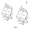
図6は、導波管システム600の上側および下側端部の近傍に位置付けられるプロジェクタ602を有する、導波管システム600を示す。特に、導波管システム600の上側端部におけるプロジェクタ602は、位置112(図1参照)に配置されることができる。このように、プロジェクタ602は、入力結合格子604の中に光を投影することができ、これは、次いで、複数の異なる表示領域606の中に再指向されることができる。表示領域606は、前述で説明される実施形態において上記に説明されるように、ユーザの眼に投影光を再指向するために直交瞳エキスパンダおよび射出瞳エキスパンダを含む導波管を組み込むことができる。導波管システム600は、表示領域606へのプロジェクタ602の近接近に起因して、直交瞳エキスパンダをごくわずかしか、またはいくつかの実施形態では、全く含み得ないことに留意されたい。本構成では、対応する表示領域606と関連付けられる入力結合格子604および射出瞳エキスパンダは、表示領域606を横断して光を協働的に分配し得る。このように、導波管システム600によって占められる空間の量が、低減された、または存在しない直交瞳エキスパンダを有する本構成のため、有意に低減されることができる。隣接する表示領域の間の角度608は、大幅に変動し得ることを理解されたい。例えば、いくつかの実施形態では、表示領域606は、上側および下側表示領域606が、約180度~約90度変動し得る角度608によってオフセットされるように、相互に対して傾斜され得る。いくつかの実施形態では、表示領域606を上向きおよび下向きに傾斜させることによって、表示領域606内に配置される射出瞳エキスパンダは、実質的に同一の設計を有することができる。一般に、両方の角度608は、ユーザの両方の眼が類似する視認体験を提示され得るように、実質的に同一であろう。
FIG. 6 shows a
図7は、ディスプレイデバイスのユーザの眼に投影光を再指向するための方法を説明する、フローチャート700を示す。702において、投影光が、ディスプレイデバイスの入力結合格子によって受け取られる。入力結合格子は、複数の入力領域を含むことができる。いくつかの実施形態では、入力領域は、1つの入力領域によって受け取られた光が隣接する入力領域と関連付けられる導波管に沿って意図せず進行することを防止する、光遮断構造によって分離されることができる。他の実施形態では、入力結合格子に入射する光によってとられる方向は、例えば、偏向ビームスプリッタによって、またはダイクロイックビームスプリッタによって等、他の手段によって制御されることができる。704において、各入力領域から受け取られた光は、直交瞳エキスパンダおよび射出瞳エキスパンダの両方を含み得る対応する導波管に沿って指向される。706において、導波管を通して透過された投影光は、対応する射出瞳エキスパンダに到着する。いくつかの実施形態では、光を入力領域から射出瞳エキスパンダに透過させる直交瞳エキスパンダは、光を射出瞳エキスパンダに向かって、それを横断して指向および分配するために、90度の角度において光を繰り返し反射する。708において、異なる射出瞳エキスパンダが、異なる角度において投影光を出力するように構成される。射出瞳エキスパンダのそれぞれから分離される光に関する分離角度は、実質的に同一であり得る。 FIG. 7 shows a flow chart 700 describing a method for redirecting projection light to a user's eye of a display device. At 702, projected light is received by an incoupling grating of a display device. An input coupling grid can include multiple input regions. In some embodiments, the input regions are separated by light blocking structures that prevent light received by one input region from unintentionally traveling along waveguides associated with adjacent input regions. can In other embodiments, the direction taken by light incident on the incoupling grating can be controlled by other means, such as, for example, by a polarizing beam splitter or by a dichroic beam splitter. At 704, light received from each input region is directed along a corresponding waveguide, which may include both a quadrature pupil expander and an exit pupil expander. At 706, projection light transmitted through the waveguide arrives at a corresponding exit pupil expander. In some embodiments, the orthogonal pupil expander, which transmits light from the input region to the exit pupil expander, uses a 90 degree angle to direct and distribute the light towards and across the exit pupil expander. Reflects light repeatedly at an angle. At 708, different exit pupil expanders are configured to output projection light at different angles. The separation angles for light separated from each of the exit pupil expanders may be substantially the same.
説明される実施形態の種々の側面、実施形態、実装、または特徴は、別個に、または任意の組み合わせにおいて使用されることができる。説明される実施形態の種々の側面は、ソフトウェア、ハードウェア、またはハードウェアおよびソフトウェアの組み合わせによって実装されることができる。説明される実施形態はまた、製造動作を制御するためのコンピュータ可読媒体上のコンピュータ可読コードとして、または製造ラインを制御するためのコンピュータ可読媒体上のコンピュータ可読コードとして、具現化されることができる。コンピュータ可読媒体は、その後、コンピュータシステムによって読み取られ得るデータを記憶し得る、任意のデータ記憶デバイスである。コンピュータ可読媒体の実施例は、読取専用メモリ、ランダムアクセスメモリ、CD-ROM、HDD、DVD、磁気テープ、および光学データ記憶デバイスを含む。コンピュータ可読媒体はまた、コンピュータ可読コードが分散方式において記憶および実行されるように、ネットワーク結合されたコンピュータシステムを経由して分散されることができる。 Various aspects, embodiments, implementations or features of the described embodiments may be used separately or in any combination. Various aspects of the described embodiments can be implemented by software, hardware, or a combination of hardware and software. The described embodiments can also be embodied as computer readable code on a computer readable medium for controlling manufacturing operations or as computer readable code on a computer readable medium for controlling a manufacturing line. . A computer-readable medium is any data storage device that can store data that can then be read by a computer system. Examples of computer-readable media include read-only memory, random-access memory, CD-ROMs, HDDs, DVDs, magnetic tapes, and optical data storage devices. The computer readable medium can also be distributed over network-coupled computer systems so that the computer readable code is stored and executed in a distributed fashion.
前述の説明は、解説の目的のために、説明される実施形態の徹底的な理解を提供するために具体的名称を使用した。しかしながら、具体的詳細は、説明される実施形態を実践するために要求されないことが当業者に明白となるであろう。したがって、具体的実施形態の前述の説明は、例証および説明の目的のために提示される。それらは、包括的であること、または説明される実施形態を開示される精密な形態に限定することを意図していない。多くの修正および変形例が、上記の教示に照らして、可能性として考えられることが当業者に明白となるであろう。 The foregoing description, for purposes of explanation, used specific nomenclature to provide a thorough understanding of the described embodiments. However, it will be apparent to one skilled in the art that the specific details are not required to practice the described embodiments. Accordingly, the foregoing descriptions of specific embodiments are presented for purposes of illustration and description. They are not intended to be exhaustive or to limit the described embodiments to the precise forms disclosed. It will be apparent to those skilled in the art that many modifications and variations are possible in light of the above teachings.
Claims (16)
画像の第1の部分および第2の部分と関連付けられた光を放出するように構成されるプロジェクタであって、前記画像の前記第1の部分は、前記画像の前記第2の部分とは実質的に異なる、プロジェクタと、
光学要素を備える導波管システムであって、前記光学要素は、
前記プロジェクタから前記画像の前記第1の部分と関連付けられた前記光を受け取ることと、前記画像の前記第1の部分と関連付けられた前記光を、第1の表示領域から第1の角度においてユーザの片方の眼に向かって再指向することとを行うように構成される第1の入力領域を有する第1の光学経路と、
第2の光学経路であって、前記第2の光学経路は、第2の入力領域を有し、前記第2の入力領域は、前記第1の入力領域に隣接し、前記プロジェクタから前記画像の前記第2の部分と関連付けられた前記光を受け取ることと、前記画像の前記第2の部分と関連付けられた前記光を、第2の表示領域から第2の角度において前記ユーザの前記片方の眼に向かって再指向することとを行うように構成され、前記第2の角度は、前記第1の角度とは異なり、前記第2の入力領域は、前記第1の入力領域と同一平面上にあり、前記第2の表示領域は、前記第1の表示領域と同一平面上にあり、かつ、前記第1の表示領域から側方にオフセットされ、前記画像の前記第1の部分と関連付けられた前記光が前記第1の表示領域において前記第1の光学経路から分離され、前記画像の前記第2の部分と関連付けられた前記光が前記第2の表示領域において前記第2の光学経路から分離されることにより、前記第1および第2の表示領域が合成画像を協働的に形成するようになっている、第2の光学経路と
を画定する、導波管システムと、
前記光が前記第1の光学経路と前記第2の光学経路との間で意図せず進行することを防止する前記第1の入力領域と前記第2の入力領域との間に位置付けられる光遮断要素と
を備える、ウェアラブルディスプレイデバイス。 A wearable display device,
A projector configured to emit light associated with a first portion and a second portion of an image, wherein the first portion of the image is substantially different from the second portion of the image. physically different projectors and
A waveguide system comprising an optical element, said optical element comprising:
receiving the light associated with the first portion of the image from the projector; and transmitting the light associated with the first portion of the image from a first display area at a first angle. a first optical path having a first input area configured to redirect toward one eye of a user;
a second optical path, said second optical path having a second input area, said second input area adjacent to said first input area, and receiving said image from said projector; receiving the light associated with the second portion; and directing the light associated with the second portion of the image to the one of the user at a second angle from a second display area . wherein the second angle is different than the first angle and the second input area is coplanar with the first input area . wherein the second display area is coplanar with the first display area and laterally offset from the first display area and associated with the first portion of the image. said light is separated from said first optical path in said first display area and said light associated with said second portion of said image is separated from said second optical path in said second display area. a second optical path separated such that the first and second display areas cooperatively form a composite image;
a waveguide system defining
A light block positioned between the first input area and the second input area to prevent the light from unintentionally traveling between the first optical path and the second optical path. element and
A wearable display device comprising:
画像の第1の部分および第2の部分と関連付けられた光を放出するように構成されるプロジェクタであって、前記画像の前記第1の部分は、前記画像の前記第2の部分とは実質的に異なる、プロジェクタと、
導波管システムであって、前記導波管システムは、
前記プロジェクタからそれぞれ前記画像の前記第1の部分および前記第2の部分と関連付けられた前記光を受け取るように構成される第1および第2の入力領域であって、前記第2の入力領域は、前記第1の入力領域と同一平面上にある、第1および第2の入力領域と、
前記第1の入力領域および前記第2の入力領域のうちの対応するものから受け取られた前記画像の前記第1の部分および前記第2の部分と関連付けられた前記光を透過するように構成される第1および第2の直交瞳エキスパンダと、
前記直交瞳エキスパンダのうちの対応するものから前記画像の前記第1の部分および前記第2の部分と関連付けられた前記光を受け取ることと、前記画像の前記第1の部分および前記第2の部分と関連付けられた前記光をユーザの片方の眼に向かって再指向することとを行うように構成される第1および第2の射出瞳エキスパンダであって、前記第1の射出瞳エキスパンダおよび前記第2の射出瞳エキスパンダは、同一平面上にあり、かつ、互いから側方にオフセットされ、前記画像の前記第1の部分と関連付けられた前記光が前記第1の射出瞳エキスパンダにおいて第1の光学経路から分離され、前記画像の前記第2の部分と関連付けられた前記光が前記第2の射出瞳エキスパンダにおいて第2の光学経路から分離される、第1および第2の射出瞳エキスパンダと
を備える、導波管システムと、
前記第1の入力領域と前記第2の入力領域との間に位置付けられる光遮断要素と
を備え、
前記第2の射出瞳エキスパンダは、前記第1の射出瞳エキスパンダとは異なる角度において前記導波管システムから前記画像の前記第2の部分と関連付けられた前記光を分離することにより、前記第1および第2の表示領域が合成画像を協働的に形成するようにするように構成される、ウェアラブルディスプレイデバイス。 A wearable display device,
A projector configured to emit light associated with a first portion and a second portion of an image, wherein the first portion of the image is substantially different from the second portion of the image. physically different projectors and
A waveguide system, said waveguide system comprising:
first and second input areas configured to receive the light respectively associated with the first portion and the second portion of the image from the projector , the second input area being , first and second input areas coplanar with the first input area ;
configured to transmit said light associated with said first portion and said second portion of said image received from corresponding ones of said first input area and said second input area; first and second orthogonal pupil expanders that
receiving the light associated with the first portion and the second portion of the image from corresponding ones of the quadrature pupil expanders; toward one eye of a user , wherein the first exit pupil expander is configured to : The expander and the second exit pupil expander are co-planar and laterally offset from each other such that the light associated with the first portion of the image extends through the first exit pupil expander. first and second optical paths separated from the first optical path at an expander and wherein the light associated with the second portion of the image is separated from the second optical path at the second exit pupil expander exit pupil expander and
a waveguide system comprising
a light blocking element positioned between the first input area and the second input area;
with
The second exit pupil expander separates the light associated with the second portion of the image from the waveguide system at a different angle than the first exit pupil expander, thereby A wearable display device configured to cause the first and second display areas to cooperatively form a composite image .
画像の第1の部分および第2の部分と関連付けられた光を放出するように構成されるプロジェクタであって、前記画像の前記第1の部分は、前記画像の前記第2の部分とは実質的に異なる、プロジェクタと、
光学要素を備える回折導波管システムであって、前記光学要素は、
第1の光学経路と、
前記第1の光学経路とは別個であり、明確に異なる第2の光学経路であって、前記第1および第2の光学経路は、前記プロジェクタから前記画像の前記第1の部分および前記第2の部分と関連付けられた前記光を受け取るように構成され、前記第1の光学経路は、前記画像の前記第1の部分と関連付けられた前記光を、第1の表示領域から第1の角度においてユーザの片方の眼に向かって分離するように構成され、前記第2の光学経路は、前記画像の前記第2の部分と関連付けられた前記光を、第2の表示領域から第2の角度において前記ユーザの前記片方の眼に向かって分離するように構成され、前記第2の角度は、前記第1の角度とは異なり、前記第2の表示領域は、前記第1の表示領域と同一平面上にあり、かつ、前記第1の表示領域から側方にオフセットされ、前記第1および第2の表示領域は、合成画像を協働的に形成する、第2の光学経路と
を画定する、回折導波管システムと、
前記光が前記第1の光学経路と前記第2の光学経路との間で意図せず進行することを防止する前記第1の光学経路と前記第2の光学経路との間に位置付けられる光遮断要素と、
前記回折導波管システムを支持するように定寸される開口部を画定するフレームであって、前記フレームは、前記ユーザの耳に係合するように構成されるテンプルを備え、前記プロジェクタは、前記テンプルに結合され、前記ユーザの前記片方の眼から離れるように前記光を指向するように構成される、フレームと
を備える、ウェアラブルディスプレイデバイス。 A wearable display device,
A projector configured to emit light associated with a first portion and a second portion of an image, wherein the first portion of the image is substantially different from the second portion of the image. physically different projectors and
A diffractive waveguide system comprising an optical element, said optical element comprising:
a first optical path;
A second optical path separate and distinct from said first optical path, said first and second optical paths directing said first portion and said second portion of said image from said projector. wherein the first optical path directs the light associated with the first portion of the image from a first display area at a first angle to configured to split toward one eye of a user, wherein the second optical path directs the light associated with the second portion of the image from a second display area at a second angle ; configured to diverge toward the one eye of the user , wherein the second angle is different than the first angle and the second display area is coplanar with the first display area; a second optical path overlying and laterally offset from said first display area, said first and second display areas cooperatively forming a composite image;
a diffractive waveguide system defining
A light block positioned between the first optical path and the second optical path to prevent the light from unintentionally traveling between the first optical path and the second optical path. element and
a frame defining an opening sized to support the diffractive waveguide system, the frame comprising temples configured to engage the ear of the user, the projector comprising: a frame coupled to the temple and configured to direct the light away from the one eye of the user;
A wearable display device comprising:
said first optical path comprising a first incoupling grating, a first orthogonal pupil expander, and a first exit pupil expander including said first display area ; said second optical path comprises a second incoupling grating adjacent to said first incoupling grating, a second orthogonal pupil expander, and a second exit pupil expander comprising said second display area. 13. The wearable display device according to 12 .
Priority Applications (1)
| Application Number | Priority Date | Filing Date | Title |
|---|---|---|---|
| JP2022123247A JP7383092B2 (en) | 2017-03-22 | 2022-08-02 | Wearable display device that utilizes multiple fields of view |
Applications Claiming Priority (3)
| Application Number | Priority Date | Filing Date | Title |
|---|---|---|---|
| US201762475087P | 2017-03-22 | 2017-03-22 | |
| US62/475,087 | 2017-03-22 | ||
| PCT/US2018/023842 WO2018175776A1 (en) | 2017-03-22 | 2018-03-22 | Wearable display device utilizing a composite field of view |
Related Child Applications (1)
| Application Number | Title | Priority Date | Filing Date |
|---|---|---|---|
| JP2022123247A Division JP7383092B2 (en) | 2017-03-22 | 2022-08-02 | Wearable display device that utilizes multiple fields of view |
Publications (2)
| Publication Number | Publication Date |
|---|---|
| JP2020514829A JP2020514829A (en) | 2020-05-21 |
| JP7118084B2 true JP7118084B2 (en) | 2022-08-15 |
Family
ID=63582487
Family Applications (2)
| Application Number | Title | Priority Date | Filing Date |
|---|---|---|---|
| JP2019551593A Active JP7118084B2 (en) | 2017-03-22 | 2018-03-22 | Wearable display device using multiple visual field |
| JP2022123247A Active JP7383092B2 (en) | 2017-03-22 | 2022-08-02 | Wearable display device that utilizes multiple fields of view |
Family Applications After (1)
| Application Number | Title | Priority Date | Filing Date |
|---|---|---|---|
| JP2022123247A Active JP7383092B2 (en) | 2017-03-22 | 2022-08-02 | Wearable display device that utilizes multiple fields of view |
Country Status (9)
| Country | Link |
|---|---|
| US (2) | US11474362B2 (en) |
| EP (1) | EP3602169A4 (en) |
| JP (2) | JP7118084B2 (en) |
| KR (2) | KR102720048B1 (en) |
| CN (2) | CN110431466B (en) |
| AU (1) | AU2018240363B2 (en) |
| CA (1) | CA3056921C (en) |
| IL (1) | IL269389B2 (en) |
| WO (1) | WO2018175776A1 (en) |
Families Citing this family (26)
| Publication number | Priority date | Publication date | Assignee | Title |
|---|---|---|---|---|
| CN110431466B (en) | 2017-03-22 | 2022-10-28 | 奇跃公司 | Wearable display device using composite field of view |
| US10598938B1 (en) * | 2018-11-09 | 2020-03-24 | Facebook Technologies, Llc | Angular selective grating coupler for waveguide display |
| CN113508580A (en) * | 2018-12-28 | 2021-10-15 | 奇跃公司 | Augmented and virtual reality display system with left and right eye shared display |
| CN115280214A (en) * | 2019-10-17 | 2022-11-01 | 奇跃公司 | Attenuation of Light Transmission Artifacts in Wearable Displays |
| WO2021178908A1 (en) | 2020-03-06 | 2021-09-10 | Magic Leap, Inc. | Angularly selective attenuation of light transmission artifacts in wearable displays |
| CN113495360A (en) * | 2020-03-20 | 2021-10-12 | 宏碁股份有限公司 | Wearable display device |
| KR102732520B1 (en) * | 2020-05-11 | 2024-11-20 | 삼성전자주식회사 | Augmented reality generating device, augmented reality display device, and augmeted reality sytem |
| WO2021237115A1 (en) * | 2020-05-22 | 2021-11-25 | Magic Leap, Inc. | Augmented and virtual reality display systems with correlated in-coupling and out-coupling optical regions |
| WO2021237168A1 (en) | 2020-05-22 | 2021-11-25 | Magic Leap, Inc. | Method and system for dual projector waveguide displays with wide field of view |
| WO2021238560A1 (en) * | 2020-05-29 | 2021-12-02 | 深圳惠牛科技有限公司 | Waveguide ar display device having large field angle, and implementation method therefor |
| KR102882500B1 (en) | 2020-06-01 | 2025-11-07 | 삼성전자주식회사 | Wearable electronic device including display |
| JP2021189379A (en) * | 2020-06-03 | 2021-12-13 | 株式会社日立エルジーデータストレージ | Image display device |
| CN115989448A (en) | 2020-06-25 | 2023-04-18 | 奇跃公司 | Tunable Attenuation of Light Transmission Artifacts in Wearable Displays |
| US12529830B2 (en) | 2020-09-16 | 2026-01-20 | Magic Leap, Inc. | Eyepieces for augmented reality display system |
| US20240094456A1 (en) * | 2021-01-22 | 2024-03-21 | Vuzix Corporation | Image light guide with compound in-coupling diffractive optic |
| KR102873240B1 (en) * | 2021-02-03 | 2025-10-20 | 스냅 인코포레이티드 | Projector Alignment System |
| CN113050221A (en) * | 2021-04-06 | 2021-06-29 | 业成科技(成都)有限公司 | Optical system and near-to-eye display device thereof |
| TWI764763B (en) * | 2021-06-18 | 2022-05-11 | 宏達國際電子股份有限公司 | Head mounted display device |
| EP4130847A1 (en) * | 2021-08-02 | 2023-02-08 | Nokia Technologies Oy | Optical apparatus, modules and devices |
| CN113504607B (en) * | 2021-09-09 | 2021-11-26 | 泉州市德源轴承实业有限公司 | Glass frame structure based on diffraction light waveguide and processing method thereof |
| CN114019697B (en) * | 2021-11-22 | 2023-07-28 | 深圳市光舟半导体技术有限公司 | Reverse light path channel waveguide assembly, AR glasses and brightness adjusting method thereof |
| CN114217436A (en) * | 2022-02-10 | 2022-03-22 | 深圳七泽技术合伙企业(有限合伙) | Display device with large exit pupil, display method, expansion method and display device for vehicle |
| CN114647082A (en) * | 2022-04-02 | 2022-06-21 | 深圳市光舟半导体技术有限公司 | Pupil expanding device, binocular display method and image display method |
| WO2024084383A1 (en) * | 2022-10-18 | 2024-04-25 | Lumus Ltd. | Double-helix onto a single light-guide optical element (loe) |
| KR20250139365A (en) * | 2023-03-31 | 2025-09-23 | 루머스 리미티드 | Optical waveguide with split aperture |
| DE102024101152B4 (en) * | 2024-01-16 | 2025-08-21 | OQmented GmbH | Projection device for multi-field projection of images or information |
Citations (3)
| Publication number | Priority date | Publication date | Assignee | Title |
|---|---|---|---|---|
| US20080198471A1 (en) | 2004-06-17 | 2008-08-21 | Lumus Ltd. | Substrate-Guided Optical Device with Wide Aperture |
| JP2009539129A (en) | 2006-06-02 | 2009-11-12 | ノキア コーポレイション | Split injection pupil expansion element |
| US20100296163A1 (en) | 2007-12-18 | 2010-11-25 | Pasi Saarikko | Exit Pupil Expanders with Wide Field-of-View |
Family Cites Families (40)
| Publication number | Priority date | Publication date | Assignee | Title |
|---|---|---|---|---|
| WO2007031992A1 (en) * | 2005-09-14 | 2007-03-22 | Mirage Innovations Ltd. | Diffraction grating with a spatially varying duty-cycle |
| DE602006005177D1 (en) * | 2005-11-03 | 2009-03-26 | Mirage Innovations Ltd | BINOCULAR OPTICAL RELAY DEVICE |
| EP3683616B1 (en) * | 2006-06-02 | 2022-03-02 | Magic Leap, Inc. | Stereoscopic exit pupil expander display |
| WO2008071830A1 (en) * | 2006-12-14 | 2008-06-19 | Nokia Corporation | Display device having two operating modes |
| EP2242419B1 (en) | 2008-02-14 | 2016-01-13 | Nokia Technologies Oy | Device and method for determining gaze direction |
| US20100149073A1 (en) * | 2008-11-02 | 2010-06-17 | David Chaum | Near to Eye Display System and Appliance |
| AU2010243329B2 (en) * | 2009-04-29 | 2014-01-30 | Snap Inc. | Head mounted display |
| US8233204B1 (en) * | 2009-09-30 | 2012-07-31 | Rockwell Collins, Inc. | Optical displays |
| US8810913B2 (en) * | 2010-01-25 | 2014-08-19 | Bae Systems Plc | Projection display |
| WO2012068543A1 (en) * | 2010-11-18 | 2012-05-24 | Flex Lighting Ii, Llc | Light emitting device comprising a lightguide film and aligned coupling lightguides |
| CA2822978C (en) * | 2010-12-24 | 2019-02-19 | Hong Hua | An ergonomic head mounted display device and optical system |
| GB201114149D0 (en) * | 2011-08-17 | 2011-10-05 | Bae Systems Plc | Projection display |
| US8548290B2 (en) * | 2011-08-23 | 2013-10-01 | Vuzix Corporation | Dynamic apertured waveguide for near-eye display |
| JP2013057782A (en) * | 2011-09-08 | 2013-03-28 | Seiko Epson Corp | Electronic equipment |
| US8903207B1 (en) * | 2011-09-30 | 2014-12-02 | Rockwell Collins, Inc. | System for and method of extending vertical field of view in head up display utilizing a waveguide combiner |
| TWI446001B (en) * | 2011-10-04 | 2014-07-21 | Automotive Res & Testing Ct | Multi-optical head development device |
| US8736963B2 (en) * | 2012-03-21 | 2014-05-27 | Microsoft Corporation | Two-dimensional exit-pupil expansion |
| WO2013167864A1 (en) * | 2012-05-11 | 2013-11-14 | Milan Momcilo Popovich | Apparatus for eye tracking |
| EP2929378A1 (en) * | 2012-12-10 | 2015-10-14 | BAE Systems PLC | Display comprising an optical waveguide and switchable diffraction gratings and method of producing the same |
| EP2938919B1 (en) | 2013-07-30 | 2018-10-24 | LEIA Inc. | Multibeam diffraction grating-based backlighting |
| US9836122B2 (en) | 2014-01-21 | 2017-12-05 | Osterhout Group, Inc. | Eye glint imaging in see-through computer display systems |
| JP2015184560A (en) * | 2014-03-25 | 2015-10-22 | ソニー株式会社 | Light guide device, image display device, and display device |
| US9798145B2 (en) * | 2014-05-23 | 2017-10-24 | Qualcomm Incorporated | Method and apparatus for see-through near eye display |
| US9740004B2 (en) | 2014-06-05 | 2017-08-22 | Making Virtual Solid—California LLC. | Pupil-expanded biocular volumetric display |
| US9477079B2 (en) * | 2014-06-25 | 2016-10-25 | Thalmic Labs Inc. | Systems, devices, and methods for wearable heads-up displays |
| CN106489177B (en) | 2014-07-18 | 2020-06-16 | 伊奎蒂公司 | Near-Eye Display with Self-Emitting Microdisplay Engine |
| US9759919B2 (en) * | 2015-01-05 | 2017-09-12 | Microsoft Technology Licensing, Llc | Virtual image display with curved light path |
| US20160231567A1 (en) * | 2015-02-09 | 2016-08-11 | Pasi Saarikko | Display System |
| US9372347B1 (en) * | 2015-02-09 | 2016-06-21 | Microsoft Technology Licensing, Llc | Display system |
| US9513480B2 (en) * | 2015-02-09 | 2016-12-06 | Microsoft Technology Licensing, Llc | Waveguide |
| CA2976903A1 (en) * | 2015-02-17 | 2016-08-25 | Thalmic Labs Inc. | Systems, devices, and methods for eyebox expansion in wearable heads-up displays |
| US10670862B2 (en) * | 2015-07-02 | 2020-06-02 | Microsoft Technology Licensing, Llc | Diffractive optical elements with asymmetric profiles |
| US10073278B2 (en) | 2015-08-27 | 2018-09-11 | Microsoft Technology Licensing, Llc | Diffractive optical element using polarization rotation grating for in-coupling |
| DE102015122055B4 (en) * | 2015-12-17 | 2018-08-30 | Carl Zeiss Ag | Optical system and method for transmitting a source image |
| EP3420388A4 (en) * | 2016-04-04 | 2019-11-27 | Akonia Holographics, LLC | EQUALIZATION OF PUPILLE |
| US9939647B2 (en) * | 2016-06-20 | 2018-04-10 | Microsoft Technology Licensing, Llc | Extended field of view in near-eye display using optically stitched imaging |
| JP2018054978A (en) * | 2016-09-30 | 2018-04-05 | セイコーエプソン株式会社 | Virtual image display device and manufacturing method thereof |
| US10371896B2 (en) | 2016-12-22 | 2019-08-06 | Magic Leap, Inc. | Color separation in planar waveguides using dichroic filters |
| US10545346B2 (en) * | 2017-01-05 | 2020-01-28 | Digilens Inc. | Wearable heads up displays |
| CN110431466B (en) | 2017-03-22 | 2022-10-28 | 奇跃公司 | Wearable display device using composite field of view |
-
2018
- 2018-03-22 CN CN201880019276.0A patent/CN110431466B/en active Active
- 2018-03-22 AU AU2018240363A patent/AU2018240363B2/en active Active
- 2018-03-22 US US15/933,298 patent/US11474362B2/en active Active
- 2018-03-22 EP EP18771557.8A patent/EP3602169A4/en active Pending
- 2018-03-22 KR KR1020237040169A patent/KR102720048B1/en active Active
- 2018-03-22 CN CN202211288289.2A patent/CN115665389B/en active Active
- 2018-03-22 JP JP2019551593A patent/JP7118084B2/en active Active
- 2018-03-22 WO PCT/US2018/023842 patent/WO2018175776A1/en not_active Ceased
- 2018-03-22 KR KR1020197030860A patent/KR102607225B1/en active Active
- 2018-03-22 CA CA3056921A patent/CA3056921C/en active Active
- 2018-03-22 IL IL269389A patent/IL269389B2/en unknown
-
2022
- 2022-08-02 JP JP2022123247A patent/JP7383092B2/en active Active
- 2022-09-15 US US17/945,748 patent/US12493192B2/en active Active
Patent Citations (3)
| Publication number | Priority date | Publication date | Assignee | Title |
|---|---|---|---|---|
| US20080198471A1 (en) | 2004-06-17 | 2008-08-21 | Lumus Ltd. | Substrate-Guided Optical Device with Wide Aperture |
| JP2009539129A (en) | 2006-06-02 | 2009-11-12 | ノキア コーポレイション | Split injection pupil expansion element |
| US20100296163A1 (en) | 2007-12-18 | 2010-11-25 | Pasi Saarikko | Exit Pupil Expanders with Wide Field-of-View |
Also Published As
| Publication number | Publication date |
|---|---|
| IL269389A (en) | 2019-11-28 |
| US12493192B2 (en) | 2025-12-09 |
| JP2022159352A (en) | 2022-10-17 |
| JP2020514829A (en) | 2020-05-21 |
| EP3602169A1 (en) | 2020-02-05 |
| CA3056921C (en) | 2024-01-09 |
| KR102607225B1 (en) | 2023-11-27 |
| AU2018240363A1 (en) | 2019-10-10 |
| US20180275415A1 (en) | 2018-09-27 |
| US11474362B2 (en) | 2022-10-18 |
| CN110431466B (en) | 2022-10-28 |
| IL269389B1 (en) | 2023-12-01 |
| US20230013334A1 (en) | 2023-01-19 |
| EP3602169A4 (en) | 2020-04-15 |
| CN115665389A (en) | 2023-01-31 |
| JP7383092B2 (en) | 2023-11-17 |
| CA3056921A1 (en) | 2018-09-27 |
| KR20230164224A (en) | 2023-12-01 |
| KR20190124798A (en) | 2019-11-05 |
| CN110431466A (en) | 2019-11-08 |
| IL269389B2 (en) | 2024-04-01 |
| CN115665389B (en) | 2024-10-29 |
| WO2018175776A1 (en) | 2018-09-27 |
| AU2018240363B2 (en) | 2023-02-23 |
| KR102720048B1 (en) | 2024-10-18 |
Similar Documents
| Publication | Publication Date | Title |
|---|---|---|
| JP7118084B2 (en) | Wearable display device using multiple visual field | |
| JP6308630B2 (en) | Directional illumination waveguide arrangement | |
| TWI849097B (en) | Method and apparatus for variable resolution screen | |
| JP6792621B2 (en) | Head-mounted display with swirling imaging light guide | |
| CN104126144B (en) | Optical beam tilt for offset head mounted display | |
| CN103620479B (en) | Eyepiece for near-to-eye display with multi-reflectors | |
| US9733477B2 (en) | Dual axis internal optical beam tilt for eyepiece of an HMD | |
| US9519153B2 (en) | Directional flat illuminators | |
| CN105008983B (en) | Metalens assembly for directional displays | |
| CN108235739A (en) | Aperture multiplier using rectangular waveguides | |
| CN103091850A (en) | Naked-eye multi-dimensional display assembly and display thereof | |
| JP2000352695A (en) | Video display device | |
| CN108476315A (en) | The method that system layout for the display system based on reflex reflection optimizes | |
| JP2021113929A (en) | Light guide member and virtual image display device |
Legal Events
| Date | Code | Title | Description |
|---|---|---|---|
| A621 | Written request for application examination |
Free format text: JAPANESE INTERMEDIATE CODE: A621 Effective date: 20210316 |
|
| A977 | Report on retrieval |
Free format text: JAPANESE INTERMEDIATE CODE: A971007 Effective date: 20220126 |
|
| A131 | Notification of reasons for refusal |
Free format text: JAPANESE INTERMEDIATE CODE: A131 Effective date: 20220225 |
|
| A521 | Request for written amendment filed |
Free format text: JAPANESE INTERMEDIATE CODE: A523 Effective date: 20220512 |
|
| TRDD | Decision of grant or rejection written | ||
| A01 | Written decision to grant a patent or to grant a registration (utility model) |
Free format text: JAPANESE INTERMEDIATE CODE: A01 Effective date: 20220704 |
|
| A61 | First payment of annual fees (during grant procedure) |
Free format text: JAPANESE INTERMEDIATE CODE: A61 Effective date: 20220802 |
|
| R150 | Certificate of patent or registration of utility model |
Ref document number: 7118084 Country of ref document: JP Free format text: JAPANESE INTERMEDIATE CODE: R150 |
|
| R250 | Receipt of annual fees |
Free format text: JAPANESE INTERMEDIATE CODE: R250 |