JP7102053B2 - Regenerative braking system and electrically driven work vehicle using it - Google Patents
Regenerative braking system and electrically driven work vehicle using it Download PDFInfo
- Publication number
- JP7102053B2 JP7102053B2 JP2018228377A JP2018228377A JP7102053B2 JP 7102053 B2 JP7102053 B2 JP 7102053B2 JP 2018228377 A JP2018228377 A JP 2018228377A JP 2018228377 A JP2018228377 A JP 2018228377A JP 7102053 B2 JP7102053 B2 JP 7102053B2
- Authority
- JP
- Japan
- Prior art keywords
- power
- power conversion
- voltage
- line
- input
- Prior art date
- Legal status (The legal status is an assumption and is not a legal conclusion. Google has not performed a legal analysis and makes no representation as to the accuracy of the status listed.)
- Active
Links
- 230000001172 regenerating effect Effects 0.000 title claims description 110
- 238000006243 chemical reaction Methods 0.000 claims description 211
- 230000008929 regeneration Effects 0.000 claims description 77
- 238000011069 regeneration method Methods 0.000 claims description 77
- 238000001514 detection method Methods 0.000 description 55
- 230000009467 reduction Effects 0.000 description 20
- 238000012545 processing Methods 0.000 description 17
- 230000008859 change Effects 0.000 description 14
- 238000000034 method Methods 0.000 description 13
- 238000010586 diagram Methods 0.000 description 10
- 230000008569 process Effects 0.000 description 8
- 230000004048 modification Effects 0.000 description 7
- 238000012986 modification Methods 0.000 description 7
- 238000004804 winding Methods 0.000 description 6
- 230000000694 effects Effects 0.000 description 4
- 238000007796 conventional method Methods 0.000 description 3
- 239000002828 fuel tank Substances 0.000 description 3
- 239000003990 capacitor Substances 0.000 description 2
- 239000003638 chemical reducing agent Substances 0.000 description 2
- 230000008878 coupling Effects 0.000 description 2
- 238000010168 coupling process Methods 0.000 description 2
- 238000005859 coupling reaction Methods 0.000 description 2
- 239000000446 fuel Substances 0.000 description 2
- 238000009413 insulation Methods 0.000 description 2
- 238000012423 maintenance Methods 0.000 description 2
- 230000001681 protective effect Effects 0.000 description 2
- 230000007704 transition Effects 0.000 description 2
- 239000013585 weight reducing agent Substances 0.000 description 2
- 230000005856 abnormality Effects 0.000 description 1
- 230000001133 acceleration Effects 0.000 description 1
- 230000009471 action Effects 0.000 description 1
- 230000037396 body weight Effects 0.000 description 1
- 239000000470 constituent Substances 0.000 description 1
- 230000008602 contraction Effects 0.000 description 1
- 238000001816 cooling Methods 0.000 description 1
- 230000007613 environmental effect Effects 0.000 description 1
- 239000002803 fossil fuel Substances 0.000 description 1
- 238000009499 grossing Methods 0.000 description 1
- 239000004065 semiconductor Substances 0.000 description 1
Images


Classifications
-
- B—PERFORMING OPERATIONS; TRANSPORTING
- B60—VEHICLES IN GENERAL
- B60L—PROPULSION OF ELECTRICALLY-PROPELLED VEHICLES; SUPPLYING ELECTRIC POWER FOR AUXILIARY EQUIPMENT OF ELECTRICALLY-PROPELLED VEHICLES; ELECTRODYNAMIC BRAKE SYSTEMS FOR VEHICLES IN GENERAL; MAGNETIC SUSPENSION OR LEVITATION FOR VEHICLES; MONITORING OPERATING VARIABLES OF ELECTRICALLY-PROPELLED VEHICLES; ELECTRIC SAFETY DEVICES FOR ELECTRICALLY-PROPELLED VEHICLES
- B60L7/00—Electrodynamic brake systems for vehicles in general
- B60L7/10—Dynamic electric regenerative braking
- B60L7/14—Dynamic electric regenerative braking for vehicles propelled by AC motors
-
- B—PERFORMING OPERATIONS; TRANSPORTING
- B60—VEHICLES IN GENERAL
- B60K—ARRANGEMENT OR MOUNTING OF PROPULSION UNITS OR OF TRANSMISSIONS IN VEHICLES; ARRANGEMENT OR MOUNTING OF PLURAL DIVERSE PRIME-MOVERS IN VEHICLES; AUXILIARY DRIVES FOR VEHICLES; INSTRUMENTATION OR DASHBOARDS FOR VEHICLES; ARRANGEMENTS IN CONNECTION WITH COOLING, AIR INTAKE, GAS EXHAUST OR FUEL SUPPLY OF PROPULSION UNITS IN VEHICLES
- B60K6/00—Arrangement or mounting of plural diverse prime-movers for mutual or common propulsion, e.g. hybrid propulsion systems comprising electric motors and internal combustion engines ; Control systems therefor, i.e. systems controlling two or more prime movers, or controlling one of these prime movers and any of the transmission, drive or drive units
- B60K6/20—Arrangement or mounting of plural diverse prime-movers for mutual or common propulsion, e.g. hybrid propulsion systems comprising electric motors and internal combustion engines ; Control systems therefor, i.e. systems controlling two or more prime movers, or controlling one of these prime movers and any of the transmission, drive or drive units the prime-movers consisting of electric motors and internal combustion engines, e.g. HEVs
- B60K6/22—Arrangement or mounting of plural diverse prime-movers for mutual or common propulsion, e.g. hybrid propulsion systems comprising electric motors and internal combustion engines ; Control systems therefor, i.e. systems controlling two or more prime movers, or controlling one of these prime movers and any of the transmission, drive or drive units the prime-movers consisting of electric motors and internal combustion engines, e.g. HEVs characterised by apparatus, components or means specially adapted for HEVs
- B60K6/26—Arrangement or mounting of plural diverse prime-movers for mutual or common propulsion, e.g. hybrid propulsion systems comprising electric motors and internal combustion engines ; Control systems therefor, i.e. systems controlling two or more prime movers, or controlling one of these prime movers and any of the transmission, drive or drive units the prime-movers consisting of electric motors and internal combustion engines, e.g. HEVs characterised by apparatus, components or means specially adapted for HEVs characterised by the motors or the generators
-
- B—PERFORMING OPERATIONS; TRANSPORTING
- B60—VEHICLES IN GENERAL
- B60K—ARRANGEMENT OR MOUNTING OF PROPULSION UNITS OR OF TRANSMISSIONS IN VEHICLES; ARRANGEMENT OR MOUNTING OF PLURAL DIVERSE PRIME-MOVERS IN VEHICLES; AUXILIARY DRIVES FOR VEHICLES; INSTRUMENTATION OR DASHBOARDS FOR VEHICLES; ARRANGEMENTS IN CONNECTION WITH COOLING, AIR INTAKE, GAS EXHAUST OR FUEL SUPPLY OF PROPULSION UNITS IN VEHICLES
- B60K6/00—Arrangement or mounting of plural diverse prime-movers for mutual or common propulsion, e.g. hybrid propulsion systems comprising electric motors and internal combustion engines ; Control systems therefor, i.e. systems controlling two or more prime movers, or controlling one of these prime movers and any of the transmission, drive or drive units
- B60K6/20—Arrangement or mounting of plural diverse prime-movers for mutual or common propulsion, e.g. hybrid propulsion systems comprising electric motors and internal combustion engines ; Control systems therefor, i.e. systems controlling two or more prime movers, or controlling one of these prime movers and any of the transmission, drive or drive units the prime-movers consisting of electric motors and internal combustion engines, e.g. HEVs
- B60K6/42—Arrangement or mounting of plural diverse prime-movers for mutual or common propulsion, e.g. hybrid propulsion systems comprising electric motors and internal combustion engines ; Control systems therefor, i.e. systems controlling two or more prime movers, or controlling one of these prime movers and any of the transmission, drive or drive units the prime-movers consisting of electric motors and internal combustion engines, e.g. HEVs characterised by the architecture of the hybrid electric vehicle
- B60K6/46—Series type
-
- B—PERFORMING OPERATIONS; TRANSPORTING
- B60—VEHICLES IN GENERAL
- B60L—PROPULSION OF ELECTRICALLY-PROPELLED VEHICLES; SUPPLYING ELECTRIC POWER FOR AUXILIARY EQUIPMENT OF ELECTRICALLY-PROPELLED VEHICLES; ELECTRODYNAMIC BRAKE SYSTEMS FOR VEHICLES IN GENERAL; MAGNETIC SUSPENSION OR LEVITATION FOR VEHICLES; MONITORING OPERATING VARIABLES OF ELECTRICALLY-PROPELLED VEHICLES; ELECTRIC SAFETY DEVICES FOR ELECTRICALLY-PROPELLED VEHICLES
- B60L3/00—Electric devices on electrically-propelled vehicles for safety purposes; Monitoring operating variables, e.g. speed, deceleration or energy consumption
- B60L3/0023—Detecting, eliminating, remedying or compensating for drive train abnormalities, e.g. failures within the drive train
- B60L3/003—Detecting, eliminating, remedying or compensating for drive train abnormalities, e.g. failures within the drive train relating to inverters
-
- B—PERFORMING OPERATIONS; TRANSPORTING
- B60—VEHICLES IN GENERAL
- B60L—PROPULSION OF ELECTRICALLY-PROPELLED VEHICLES; SUPPLYING ELECTRIC POWER FOR AUXILIARY EQUIPMENT OF ELECTRICALLY-PROPELLED VEHICLES; ELECTRODYNAMIC BRAKE SYSTEMS FOR VEHICLES IN GENERAL; MAGNETIC SUSPENSION OR LEVITATION FOR VEHICLES; MONITORING OPERATING VARIABLES OF ELECTRICALLY-PROPELLED VEHICLES; ELECTRIC SAFETY DEVICES FOR ELECTRICALLY-PROPELLED VEHICLES
- B60L50/00—Electric propulsion with power supplied within the vehicle
- B60L50/10—Electric propulsion with power supplied within the vehicle using propulsion power supplied by engine-driven generators, e.g. generators driven by combustion engines
- B60L50/15—Electric propulsion with power supplied within the vehicle using propulsion power supplied by engine-driven generators, e.g. generators driven by combustion engines with additional electric power supply
-
- B—PERFORMING OPERATIONS; TRANSPORTING
- B60—VEHICLES IN GENERAL
- B60L—PROPULSION OF ELECTRICALLY-PROPELLED VEHICLES; SUPPLYING ELECTRIC POWER FOR AUXILIARY EQUIPMENT OF ELECTRICALLY-PROPELLED VEHICLES; ELECTRODYNAMIC BRAKE SYSTEMS FOR VEHICLES IN GENERAL; MAGNETIC SUSPENSION OR LEVITATION FOR VEHICLES; MONITORING OPERATING VARIABLES OF ELECTRICALLY-PROPELLED VEHICLES; ELECTRIC SAFETY DEVICES FOR ELECTRICALLY-PROPELLED VEHICLES
- B60L50/00—Electric propulsion with power supplied within the vehicle
- B60L50/50—Electric propulsion with power supplied within the vehicle using propulsion power supplied by batteries or fuel cells
- B60L50/60—Electric propulsion with power supplied within the vehicle using propulsion power supplied by batteries or fuel cells using power supplied by batteries
- B60L50/61—Electric propulsion with power supplied within the vehicle using propulsion power supplied by batteries or fuel cells using power supplied by batteries by batteries charged by engine-driven generators, e.g. series hybrid electric vehicles
-
- B—PERFORMING OPERATIONS; TRANSPORTING
- B60—VEHICLES IN GENERAL
- B60L—PROPULSION OF ELECTRICALLY-PROPELLED VEHICLES; SUPPLYING ELECTRIC POWER FOR AUXILIARY EQUIPMENT OF ELECTRICALLY-PROPELLED VEHICLES; ELECTRODYNAMIC BRAKE SYSTEMS FOR VEHICLES IN GENERAL; MAGNETIC SUSPENSION OR LEVITATION FOR VEHICLES; MONITORING OPERATING VARIABLES OF ELECTRICALLY-PROPELLED VEHICLES; ELECTRIC SAFETY DEVICES FOR ELECTRICALLY-PROPELLED VEHICLES
- B60L7/00—Electrodynamic brake systems for vehicles in general
- B60L7/10—Dynamic electric regenerative braking
- B60L7/12—Dynamic electric regenerative braking for vehicles propelled by DC motors
-
- B—PERFORMING OPERATIONS; TRANSPORTING
- B60—VEHICLES IN GENERAL
- B60L—PROPULSION OF ELECTRICALLY-PROPELLED VEHICLES; SUPPLYING ELECTRIC POWER FOR AUXILIARY EQUIPMENT OF ELECTRICALLY-PROPELLED VEHICLES; ELECTRODYNAMIC BRAKE SYSTEMS FOR VEHICLES IN GENERAL; MAGNETIC SUSPENSION OR LEVITATION FOR VEHICLES; MONITORING OPERATING VARIABLES OF ELECTRICALLY-PROPELLED VEHICLES; ELECTRIC SAFETY DEVICES FOR ELECTRICALLY-PROPELLED VEHICLES
- B60L7/00—Electrodynamic brake systems for vehicles in general
- B60L7/10—Dynamic electric regenerative braking
- B60L7/16—Dynamic electric regenerative braking for vehicles comprising converters between the power source and the motor
-
- B—PERFORMING OPERATIONS; TRANSPORTING
- B60—VEHICLES IN GENERAL
- B60L—PROPULSION OF ELECTRICALLY-PROPELLED VEHICLES; SUPPLYING ELECTRIC POWER FOR AUXILIARY EQUIPMENT OF ELECTRICALLY-PROPELLED VEHICLES; ELECTRODYNAMIC BRAKE SYSTEMS FOR VEHICLES IN GENERAL; MAGNETIC SUSPENSION OR LEVITATION FOR VEHICLES; MONITORING OPERATING VARIABLES OF ELECTRICALLY-PROPELLED VEHICLES; ELECTRIC SAFETY DEVICES FOR ELECTRICALLY-PROPELLED VEHICLES
- B60L7/00—Electrodynamic brake systems for vehicles in general
- B60L7/22—Dynamic electric resistor braking, combined with dynamic electric regenerative braking
-
- B—PERFORMING OPERATIONS; TRANSPORTING
- B60—VEHICLES IN GENERAL
- B60W—CONJOINT CONTROL OF VEHICLE SUB-UNITS OF DIFFERENT TYPE OR DIFFERENT FUNCTION; CONTROL SYSTEMS SPECIALLY ADAPTED FOR HYBRID VEHICLES; ROAD VEHICLE DRIVE CONTROL SYSTEMS FOR PURPOSES NOT RELATED TO THE CONTROL OF A PARTICULAR SUB-UNIT
- B60W20/00—Control systems specially adapted for hybrid vehicles
- B60W20/50—Control strategies for responding to system failures, e.g. for fault diagnosis, failsafe operation or limp mode
-
- B—PERFORMING OPERATIONS; TRANSPORTING
- B60—VEHICLES IN GENERAL
- B60W—CONJOINT CONTROL OF VEHICLE SUB-UNITS OF DIFFERENT TYPE OR DIFFERENT FUNCTION; CONTROL SYSTEMS SPECIALLY ADAPTED FOR HYBRID VEHICLES; ROAD VEHICLE DRIVE CONTROL SYSTEMS FOR PURPOSES NOT RELATED TO THE CONTROL OF A PARTICULAR SUB-UNIT
- B60W30/00—Purposes of road vehicle drive control systems not related to the control of a particular sub-unit, e.g. of systems using conjoint control of vehicle sub-units
- B60W30/18—Propelling the vehicle
- B60W30/18009—Propelling the vehicle related to particular drive situations
- B60W30/18109—Braking
- B60W30/18127—Regenerative braking
-
- H—ELECTRICITY
- H02—GENERATION; CONVERSION OR DISTRIBUTION OF ELECTRIC POWER
- H02M—APPARATUS FOR CONVERSION BETWEEN AC AND AC, BETWEEN AC AND DC, OR BETWEEN DC AND DC, AND FOR USE WITH MAINS OR SIMILAR POWER SUPPLY SYSTEMS; CONVERSION OF DC OR AC INPUT POWER INTO SURGE OUTPUT POWER; CONTROL OR REGULATION THEREOF
- H02M1/00—Details of apparatus for conversion
- H02M1/32—Means for protecting converters other than automatic disconnection
- H02M1/325—Means for protecting converters other than automatic disconnection with means for allowing continuous operation despite a fault, i.e. fault tolerant converters
-
- B—PERFORMING OPERATIONS; TRANSPORTING
- B60—VEHICLES IN GENERAL
- B60L—PROPULSION OF ELECTRICALLY-PROPELLED VEHICLES; SUPPLYING ELECTRIC POWER FOR AUXILIARY EQUIPMENT OF ELECTRICALLY-PROPELLED VEHICLES; ELECTRODYNAMIC BRAKE SYSTEMS FOR VEHICLES IN GENERAL; MAGNETIC SUSPENSION OR LEVITATION FOR VEHICLES; MONITORING OPERATING VARIABLES OF ELECTRICALLY-PROPELLED VEHICLES; ELECTRIC SAFETY DEVICES FOR ELECTRICALLY-PROPELLED VEHICLES
- B60L2200/00—Type of vehicles
- B60L2200/40—Working vehicles
-
- B—PERFORMING OPERATIONS; TRANSPORTING
- B60—VEHICLES IN GENERAL
- B60L—PROPULSION OF ELECTRICALLY-PROPELLED VEHICLES; SUPPLYING ELECTRIC POWER FOR AUXILIARY EQUIPMENT OF ELECTRICALLY-PROPELLED VEHICLES; ELECTRODYNAMIC BRAKE SYSTEMS FOR VEHICLES IN GENERAL; MAGNETIC SUSPENSION OR LEVITATION FOR VEHICLES; MONITORING OPERATING VARIABLES OF ELECTRICALLY-PROPELLED VEHICLES; ELECTRIC SAFETY DEVICES FOR ELECTRICALLY-PROPELLED VEHICLES
- B60L2240/00—Control parameters of input or output; Target parameters
- B60L2240/40—Drive Train control parameters
- B60L2240/42—Drive Train control parameters related to electric machines
- B60L2240/427—Voltage
-
- B—PERFORMING OPERATIONS; TRANSPORTING
- B60—VEHICLES IN GENERAL
- B60W—CONJOINT CONTROL OF VEHICLE SUB-UNITS OF DIFFERENT TYPE OR DIFFERENT FUNCTION; CONTROL SYSTEMS SPECIALLY ADAPTED FOR HYBRID VEHICLES; ROAD VEHICLE DRIVE CONTROL SYSTEMS FOR PURPOSES NOT RELATED TO THE CONTROL OF A PARTICULAR SUB-UNIT
- B60W2300/00—Indexing codes relating to the type of vehicle
- B60W2300/12—Trucks; Load vehicles
- B60W2300/125—Heavy duty trucks
-
- B—PERFORMING OPERATIONS; TRANSPORTING
- B60—VEHICLES IN GENERAL
- B60Y—INDEXING SCHEME RELATING TO ASPECTS CROSS-CUTTING VEHICLE TECHNOLOGY
- B60Y2200/00—Type of vehicle
- B60Y2200/90—Vehicles comprising electric prime movers
- B60Y2200/92—Hybrid vehicles
-
- B—PERFORMING OPERATIONS; TRANSPORTING
- B60—VEHICLES IN GENERAL
- B60Y—INDEXING SCHEME RELATING TO ASPECTS CROSS-CUTTING VEHICLE TECHNOLOGY
- B60Y2400/00—Special features of vehicle units
- B60Y2400/30—Sensors
- B60Y2400/308—Electric sensors
- B60Y2400/3086—Electric voltages sensors
-
- H—ELECTRICITY
- H02—GENERATION; CONVERSION OR DISTRIBUTION OF ELECTRIC POWER
- H02M—APPARATUS FOR CONVERSION BETWEEN AC AND AC, BETWEEN AC AND DC, OR BETWEEN DC AND DC, AND FOR USE WITH MAINS OR SIMILAR POWER SUPPLY SYSTEMS; CONVERSION OF DC OR AC INPUT POWER INTO SURGE OUTPUT POWER; CONTROL OR REGULATION THEREOF
- H02M1/00—Details of apparatus for conversion
- H02M1/0067—Converter structures employing plural converter units, other than for parallel operation of the units on a single load
- H02M1/0074—Plural converter units whose inputs are connected in series
-
- H—ELECTRICITY
- H02—GENERATION; CONVERSION OR DISTRIBUTION OF ELECTRIC POWER
- H02M—APPARATUS FOR CONVERSION BETWEEN AC AND AC, BETWEEN AC AND DC, OR BETWEEN DC AND DC, AND FOR USE WITH MAINS OR SIMILAR POWER SUPPLY SYSTEMS; CONVERSION OF DC OR AC INPUT POWER INTO SURGE OUTPUT POWER; CONTROL OR REGULATION THEREOF
- H02M1/00—Details of apparatus for conversion
- H02M1/0067—Converter structures employing plural converter units, other than for parallel operation of the units on a single load
- H02M1/0077—Plural converter units whose outputs are connected in series
-
- H—ELECTRICITY
- H02—GENERATION; CONVERSION OR DISTRIBUTION OF ELECTRIC POWER
- H02M—APPARATUS FOR CONVERSION BETWEEN AC AND AC, BETWEEN AC AND DC, OR BETWEEN DC AND DC, AND FOR USE WITH MAINS OR SIMILAR POWER SUPPLY SYSTEMS; CONVERSION OF DC OR AC INPUT POWER INTO SURGE OUTPUT POWER; CONTROL OR REGULATION THEREOF
- H02M1/00—Details of apparatus for conversion
- H02M1/32—Means for protecting converters other than automatic disconnection
- H02M1/322—Means for rapidly discharging a capacitor of the converter for protecting electrical components or for preventing electrical shock
-
- Y—GENERAL TAGGING OF NEW TECHNOLOGICAL DEVELOPMENTS; GENERAL TAGGING OF CROSS-SECTIONAL TECHNOLOGIES SPANNING OVER SEVERAL SECTIONS OF THE IPC; TECHNICAL SUBJECTS COVERED BY FORMER USPC CROSS-REFERENCE ART COLLECTIONS [XRACs] AND DIGESTS
- Y02—TECHNOLOGIES OR APPLICATIONS FOR MITIGATION OR ADAPTATION AGAINST CLIMATE CHANGE
- Y02T—CLIMATE CHANGE MITIGATION TECHNOLOGIES RELATED TO TRANSPORTATION
- Y02T10/00—Road transport of goods or passengers
- Y02T10/60—Other road transportation technologies with climate change mitigation effect
- Y02T10/64—Electric machine technologies in electromobility
-
- Y—GENERAL TAGGING OF NEW TECHNOLOGICAL DEVELOPMENTS; GENERAL TAGGING OF CROSS-SECTIONAL TECHNOLOGIES SPANNING OVER SEVERAL SECTIONS OF THE IPC; TECHNICAL SUBJECTS COVERED BY FORMER USPC CROSS-REFERENCE ART COLLECTIONS [XRACs] AND DIGESTS
- Y02—TECHNOLOGIES OR APPLICATIONS FOR MITIGATION OR ADAPTATION AGAINST CLIMATE CHANGE
- Y02T—CLIMATE CHANGE MITIGATION TECHNOLOGIES RELATED TO TRANSPORTATION
- Y02T10/00—Road transport of goods or passengers
- Y02T10/60—Other road transportation technologies with climate change mitigation effect
- Y02T10/70—Energy storage systems for electromobility, e.g. batteries
-
- Y—GENERAL TAGGING OF NEW TECHNOLOGICAL DEVELOPMENTS; GENERAL TAGGING OF CROSS-SECTIONAL TECHNOLOGIES SPANNING OVER SEVERAL SECTIONS OF THE IPC; TECHNICAL SUBJECTS COVERED BY FORMER USPC CROSS-REFERENCE ART COLLECTIONS [XRACs] AND DIGESTS
- Y02—TECHNOLOGIES OR APPLICATIONS FOR MITIGATION OR ADAPTATION AGAINST CLIMATE CHANGE
- Y02T—CLIMATE CHANGE MITIGATION TECHNOLOGIES RELATED TO TRANSPORTATION
- Y02T10/00—Road transport of goods or passengers
- Y02T10/60—Other road transportation technologies with climate change mitigation effect
- Y02T10/7072—Electromobility specific charging systems or methods for batteries, ultracapacitors, supercapacitors or double-layer capacitors
Landscapes
- Engineering & Computer Science (AREA)
- Transportation (AREA)
- Mechanical Engineering (AREA)
- Power Engineering (AREA)
- Life Sciences & Earth Sciences (AREA)
- Sustainable Development (AREA)
- Sustainable Energy (AREA)
- Automation & Control Theory (AREA)
- Biomedical Technology (AREA)
- General Health & Medical Sciences (AREA)
- Health & Medical Sciences (AREA)
- Chemical & Material Sciences (AREA)
- Combustion & Propulsion (AREA)
- Inverter Devices (AREA)
- Electric Propulsion And Braking For Vehicles (AREA)
- Hybrid Electric Vehicles (AREA)
Description
本発明は、回生制動システム、及び、それを用いた電気駆動作業車両に関する。 The present invention relates to a regenerative braking system and an electrically driven work vehicle using the regenerative braking system.
近年、化石燃料の枯渇や地球環境問題の悪化を背景として、ハイブリッド自動車や電気自動車のように電気エネルギーを利用した電動車両への関心が高まっており、また、実用化されている。例えば、鉱山現場においては様々な電気駆動の作業車両が使用されており、搬送用途の作業車両としては、電気駆動ダンプトラックなどが用いられている。電気駆動ダンプトラックとしては、エンジンに接続された主機発電機の発電電力をインバータによって変換して走行モータを駆動する電気駆動システムを用いる場合などがある。このような電気駆動システムを搭載したダンプトラックでは、リタード(制動)時に走行モータが生み出す回生電力を補機に供給する、所謂、回生制動システムを搭載することによって、省エネルギー化や燃料消費量低減を実現できると考えられる。 In recent years, against the background of the depletion of fossil fuels and the worsening of global environmental problems, there has been increasing interest in electric vehicles that use electric energy, such as hybrid vehicles and electric vehicles, and they have been put into practical use. For example, various electrically driven work vehicles are used at a mine site, and an electrically driven dump truck or the like is used as a work vehicle for transportation. As the electric drive dump truck, there is a case where an electric drive system for driving a traveling motor is used by converting the electric power generated by the main generator connected to the engine by an inverter. Dump trucks equipped with such an electric drive system are equipped with a so-called regenerative braking system that supplies the regenerative power generated by the traveling motor to auxiliary equipment during retard (braking) to save energy and reduce fuel consumption. It is thought that it can be realized.
ところで、回生制動システムでは、走行モータが接続される主機系と補機系とで電圧に差があるため、走行モータ用インバータが接続される直流ラインの電圧を変換して、補機が接続される直流ラインに出力する電力回生装置が必要となる。また、一般に主機系と補機系は電気的に絶縁されている必要があるため、電力回生装置ではトランスを用いてその入出力間を絶縁する。一方、ダンプトラックのように車体重量が大きい電気駆動作業車両では主機系の直流ラインの電圧は一般的に高くなるため、電力回生装置は高電圧入力に対応する必要がある。 By the way, in the regenerative braking system, since there is a difference in voltage between the main engine system and the auxiliary equipment system to which the traveling motor is connected, the auxiliary equipment is connected by converting the voltage of the DC line to which the traveling motor inverter is connected. A power regenerator that outputs to the DC line is required. Further, since the main engine system and the auxiliary engine system generally need to be electrically insulated, a transformer is used in the power regenerative device to insulate between the input and output. On the other hand, in an electrically driven work vehicle having a large body weight such as a dump truck, the voltage of the DC line of the main engine system is generally high, so that the power regenerator needs to support a high voltage input.
このような高電圧入力に対応する技術として、例えば、特許文献1には、複数台の単相インバータの出力端をそれぞれ直列接続したU,V,W相構成により、三相高圧出力を得る直接高圧インバータ装置であって、前記U,V,W相の出力端に、それぞれ1台の予備単相インバータの出力端を直列接続し、前記U,V,W相を構成する各単相インバータの出力端および前記予備単相インバータの出力端を個別に短絡できる開閉器を設け、通常運転時は、前記予備単相インバータの出力端を前記開閉器によって短絡状態にして前記U,V,W相の各単相インバータを運転し、前記U,V,W相の少なくとも1つの相で1台の単相インバータが故障発生した時は、当該故障発生した単相インバータの出力端を前記開閉器で短絡状態にし、故障発生した相と同一相の前記予備単相インバータの前記開閉器を開放および該予備単相インバータの運転で装置運転を再開する直接高圧インバータ装置が開示されている。
As a technique corresponding to such a high voltage input, for example, in
上記従来技術においては、電力変換装置である単相インバータをモジュールとして捉え、複数のモジュールを直列接続することで1つの電力変換装置を構成することにより、電力変換装置を構成する各モジュールに印加される電圧が分散(分圧)されるため、モジュール1台あたりに印加される電圧は低くなる。したがって、低耐圧のモジュールを用いて高電圧に対応することが可能となる。 In the above-mentioned prior art, a single-phase inverter which is a power conversion device is regarded as a module, and one power conversion device is configured by connecting a plurality of modules in series, so that the power conversion device is applied to each module constituting the power conversion device. Since the voltage is distributed (divided), the voltage applied to each module becomes low. Therefore, it is possible to cope with a high voltage by using a module having a low withstand voltage.
ところで、上記従来技術においては、故障や保守作業を行う必要が生じた場合に、各モジュールの出力にバイパス手段として接続された開閉器によって出力端子間をバイパス(短絡)状態にすることにより、一部のモジュールを停止させて残りのモジュールにより運転を継続可能としている。また、予備のモジュールを設けており、一部のモジュールを停止させる場合に予備のモジュールを用いることで、出力電圧を低下させずに運転を継続させている。 By the way, in the above-mentioned prior art, when a failure or maintenance work needs to be performed, the output terminals are bypassed (short-circuited) by a switch connected to the output of each module as a bypass means. The module of the part is stopped and the operation can be continued by the remaining modules. Further, a spare module is provided, and by using the spare module when stopping a part of the modules, the operation is continued without lowering the output voltage.
しかしながら、上記従来技術においては、予備モジュールを設ける必要があるため、その分だけ電力変換装置全体が大型化してしまうという課題がある。また、各モジュールのバイパス手段(開閉器)を短絡して一部のモジュールを停止させ、残りのモジュールで運転を継続することも考えられるが、この場合には残りのモジュールに印加される電圧が増加してしまう。このため、各モジュールが電圧の増加に耐えられるよう、予め各モジュールの部品を高耐圧化したり、各モジュール内での絶縁距離を確保したりする必要が生じてしまう。したがって、この場合においても、モジュールが大型化してしまう、すなわち、電力変換装置全体が大型化してしまうという課題がある。 However, in the above-mentioned conventional technique, since it is necessary to provide a spare module, there is a problem that the entire power conversion device becomes large by that amount. It is also conceivable to short-circuit the bypass means (switch) of each module to stop some modules and continue operation with the remaining modules. In this case, the voltage applied to the remaining modules is It will increase. Therefore, in order for each module to withstand an increase in voltage, it becomes necessary to increase the withstand voltage of each module component in advance and to secure an insulation distance within each module. Therefore, even in this case, there is a problem that the module becomes large, that is, the entire power conversion device becomes large.
本発明は上記に鑑みてなされたものであり、装置の大型化を防止しつつ運転の継続性を向上することができる回生制動システム、及び、それを用いた電気駆動作業車両を提供することを目的とする。 The present invention has been made in view of the above, and provides a regenerative braking system capable of improving the continuity of operation while preventing an increase in size of the device, and an electrically driven work vehicle using the regenerative braking system. The purpose.
本願は上記課題を解決する手段を複数含んでいるが、その一例を挙げるならば、エンジンに接続される第一の発電機および第二の発電機と、前記第一の発電機に接続され、前記第一の発電機の出力を整流して直流電力として第一の直流ラインに出力する第一の整流回路と、前記第一の直流ラインと走行モータとの間に接続されるインバータと、前記第一の直流ラインに接続され、前記第一の直流ラインの電力を消費可能な電力消費装置と、前記第二の発電機に接続され、前記第二の発電機の出力を整流して直流電力として第二の直流ラインに出力する第二の整流回路と、前記第二の直流ラインに接続される補機装置と、前記第一の直流ラインの電力を変換して前記第二の直流ラインに供給する電力回生装置と、前記第一の発電機、前記電力消費装置、および、前記電力回生装置を制御する制御装置とを備えた回生制動システムにおいて、前記電力回生装置は、前記第一の直流ラインからの電力を入力する入力部が直列接続された複数の電力変換モジュールと、前記複数の電力変換モジュールの入力部にそれぞれ接続され、前記入力部の正極端子と負極端子の間を個別に短絡可能な第一のバイパス装置群とを備え、前記制御装置は、前記第一の直流ラインから前記電力回生装置に入力される電圧が前記複数の電力変換モジュールの耐電圧特性の合計に基づく可変上限値を超えないように前記第一の発電機、前記電力消費装置、及び、前記電力回生装置を制御し、前記複数の電力変換モジュールの一部を停止させる場合に、停止させる電力変換モジュールの入力部の正極端子と負極端子の間を前記第一のバイパス装置群によって短絡するとともに、前記可変上限値を前記複数の電力変換モジュールのうち停止させる前記一部の電力変換モジュールの耐電圧特性に応じて低減するものとする。 The present application includes a plurality of means for solving the above problems, for example, a first generator and a second generator connected to an engine, and a first generator connected to the first generator. The first rectifying circuit that rectifies the output of the first generator and outputs it as DC power to the first DC line, the inverter connected between the first DC line and the traveling motor, and the above. A power consuming device connected to the first DC line and capable of consuming the power of the first DC line, and a DC power connected to the second generator and rectifying the output of the second generator. The second rectifying circuit that outputs to the second DC line, the auxiliary equipment connected to the second DC line, and the power of the first DC line are converted into the second DC line. In a regenerative braking system including a power regenerating device to be supplied, the first generator, the power consuming device, and a control device for controlling the power regenerating device, the power regenerating device is the first direct current. A plurality of power conversion modules in which input units for inputting power from a line are connected in series and a plurality of power conversion modules are connected to each other, and the positive terminal and the negative terminal of the input unit are individually short-circuited. The control device includes a first possible bypass device group, and the control device has a variable upper limit in which the voltage input from the first DC line to the power regenerator device is based on the sum of the withstand voltage characteristics of the plurality of power conversion modules. Input of the power conversion module to be stopped when a part of the plurality of power conversion modules is stopped by controlling the first generator, the power consuming device, and the power regeneration device so as not to exceed the value. The positive and negative terminals of the unit are short-circuited by the first bypass device group, and the variable upper limit value is stopped among the plurality of power conversion modules according to the withstand voltage characteristics of some of the power conversion modules. It shall be reduced.
本発明によれば、装置の大型化を防止しつつ運転の継続性を向上することができる回生制動システム、及び、それを用いた電気駆動作業車両を提供することができる。 According to the present invention, it is possible to provide a regenerative braking system capable of improving the continuity of operation while preventing an increase in size of the apparatus, and an electrically driven work vehicle using the regenerative braking system.
以下、本発明の実施の形態を図面を参照しつつ説明する。なお、本実施の形態では、電気駆動作業車両の一例として電気駆動ダンプトラックを示して説明するが、例えば、電気駆動ホイールローダのような他の電気駆動作業車両であっても本発明の適用が可能である。 Hereinafter, embodiments of the present invention will be described with reference to the drawings. In the present embodiment, the electric drive dump truck will be described as an example of the electric drive work vehicle, but the present invention can be applied to other electric drive work vehicles such as the electric drive wheel loader, for example. It is possible.
<第1の実施の形態>
本発明の第1の実施の形態を図1~図7参照しつつ説明する。
<First Embodiment>
The first embodiment of the present invention will be described with reference to FIGS. 1 to 7.
図1は、本実施の形態に係る電気駆動ダンプトラックの外観を模式的に示す側面図である。また、図2は、電気駆動ダンプトラックの回生制動システムを含む電気駆動システムを概略的に示す図である。図1及び図2においては、従動輪、駆動輪、及び、走行モータ等は、左右一対の構成のうちの一方のみを図示して符号を付し、他方については図中に括弧書きで符号のみを示して図示を省略する。 FIG. 1 is a side view schematically showing the appearance of the electrically driven dump truck according to the present embodiment. Further, FIG. 2 is a diagram schematically showing an electric drive system including a regenerative braking system for an electric drive dump truck. In FIGS. 1 and 2, for the driven wheel, the driving wheel, the traveling motor, etc., only one of the pair of left and right configurations is illustrated and designated, and the other is indicated by parentheses in the drawing. Is shown and the illustration is omitted.
図1及び図2において、電気駆動ダンプトラック100は、前後方向に延在して支持構造体を形成する車体フレーム1と、車体フレーム1の上部に前後方向に延在するように配置され、その後端下部をピン結合部5aを介して車体フレーム1に傾動可能に設けられた荷台(ベッセル)5と、車体フレーム1の下方前側左右に設けられた一対の従動輪(前輪)2L,2Rと、車体の下方後側左右に設けられた一対の駆動輪(後輪)3L,3Rと、車体フレーム1の上方前側に設けられた運転室4と、車体フレーム1の下方に設けられた燃料タンク9と、車体フレーム1上に配置され、燃料タンク9から供給される燃料により駆動するエンジン11と、エンジン11に接続されて駆動される主機発電機12(第一の発電機)及び主機発電機12から出力される電力を用いて車輪(駆動輪3L,3R)を駆動する走行モータ10L,10R等を有する電気駆動システムとから概略構成されている。走行モータ10L,10Rは、減速機3aL,3aRとともに駆動輪3L,3Rの回転軸部に収められている。車体フレーム1と荷台5とはホイストシリンダ6により接続されており、ホイストシリンダ6の伸縮によって荷台5がピン結合部5aを中心に回動される。
In FIGS. 1 and 2, the electrically driven
車体フレーム1には、オペレータが歩行可能なデッキが取り付けられており、オペレータはデッキを介して運転室4への移動が可能である。運転室4の内部には、図示しないアクセルペダル、ブレーキペダル、ホイストペダル、ハンドルなどが設置されている。オペレータは運転室4内のアクセルペダルやブレーキペダルの踏み込み量により電気駆動ダンプトラック100の加速力や制動力を制御し、ハンドルを左右に回転させることによって油圧駆動による操舵操作を行い、ホイストペダルを踏み込むことにより油圧駆動による荷台5のダンプ操作を行う。
A deck on which the operator can walk is attached to the
運転室4の後方には、各種電力機器が収納されたコントロールキャビネット8と、余剰エネルギーを熱として放散するための複数のh7とが搭載されている。なお、図1には図示しないが、車体フレーム1における左右の前輪2L,2Rの間に位置する部分には、エンジン11や主機発電機12の他に、補機類用の電力源である補機発電機31や油圧機器用の油圧源であるメインポンプ(図示せず)などが搭載されている。
Behind the driver's cab 4, a
図2において、電気駆動ダンプトラック100の回生制動システムは、エンジン11に接続される主機発電機12(第一の発電機)および補機発電機31(第二の発電機)と、主機発電機12に接続され、主機発電機12の出力を整流して直流電力として主機直流ライン16(第一の直流ライン)に出力する整流回路14(第一の整流回路)と、主機直流ライン16と走行モータ10L,10Rとの間に接続される走行モータ用のインバータ13L,13Rと、主機直流ライン16の電力を消費可能な電力消費装置15と、補機発電機31に接続され、補機発電機31の出力を整流して直流電力として補機直流ライン34(第二の直流ライン)に出力する整流回路32(第二の整流回路)と、補機直流ライン34に接続される補機装置33と、主機直流ライン16の電力を変換して補機直流ライン34に供給する電力回生装置21と、主機発電機12、電力消費装置15、および、電力回生装置21を制御する制御装置41とを備えている。
In FIG. 2, the regenerative braking system of the electrically driven
なお、図2においては、図面の簡単のために制御装置41から電力回生装置21に出力される制御信号を1本の信号線に集約して示しているが、後述するように、各電力変換モジュール221~22N、各バイパス装置231~23N,241~24Nへの制御信号、リレー25への制御信号など、複数の信号を含んでいる。同様に、電力回生装置21から制御装置41に出力される検出信号なども1本の信号線に集約して示したが、後述するように、電力回生装置21の各電力変換モジュール221~22Nが検出した電圧や電流、温度などの物理量や、その他の状態量など、複数の情報を含んでいる。
In FIG. 2, the control signals output from the
インバータ13L,13Rは、スイッチング素子として、例えば、IGBT(Insulated Gate Bipolar Transistor)を用いて構成される。
The
整流回路14は、主機発電機12の出力を整流して直流電力として主機直流ライン16に出力するものであり、例えば、ダイオードを用いて構成される。なお、整流回路14の代わりにスイッチング素子を用いたコンバータを用いてもよい。
The
電力消費装置15は、制御装置41からの指令信号に基づいて、主機直流ライン16の電力を消費するものであり、主機直流ライン16の正負の2極間に直列に接続されてチョッパを構成するスイッチング素子152及びダイオード153と、スイッチング素子152に並列に接続される抵抗151とを有している。抵抗151は、グリッドボックス7に搭載されている。スイッチング素子152としては、例えば、IGBTが用いられる。
The
なお、インバータ13L,13Rに用いるスイッチング素子、及び、電力消費装置15に用いるスイッチング素子152としてIGBTを用いる場合を例示して説明したが、これに限られず、例えば、MOSFET(Metal-Oxide-Semiconductor Field Effect Transistor)などの他種のスイッチング素子を用いる構成としてもよい。
The case where the IGBT is used as the switching element used for the
主機直流ライン16の正負の2極間には、主機直流ライン16の電圧を検出する電圧検出器17が接続されている。電圧検出器17で検出された電圧値(検出値)は制御装置41に出力される。
A
補機装置33は、例えば、エアコン用のインバータ及びコンプレッサモータシステムや、機器冷却用のインバータ及びブロアモータシステムなどである。なお、図2においては、これらを1個の等価インピーダンスとみなして補機装置33として図示している。なお、図2においては図示を省略したが、補機直流ライン34には、補機装置33の他にバッテリやコンデンサ、電圧検出器などが接続されている。
The auxiliary device 33 is, for example, an inverter and a compressor motor system for an air conditioner, an inverter and a blower motor system for cooling equipment, and the like. In FIG. 2, these are regarded as one equivalent impedance and are shown as an auxiliary device 33. Although not shown in FIG. 2, a battery, a capacitor, a voltage detector, and the like are connected to the
電力回生装置21は、主機系(主機直流ライン16)と補機系(補機直流ライン34)との間に接続されており、主機直流ライン16の電力(ここでは電圧)を変換して、補機直流ライン34に給電する。すなわち、電力回生装置21は、主機直流ライン16で用いる電圧を補機直流ライン34で用いる電圧に変換して出力している。補機装置33は、補機発電機31から整流回路32を介して供給される電力と、電力回生装置21はから供給される電力とにより駆動される。
The power
電力回生装置21は、入力部221a~22Na及び出力部221b~22Nbが、それぞれ、主機直流ライン16の正負の2極の間および補機直流ライン34の正負の2極の間に直列に接続される複数(例えばN台:Nは2以上の正の整数)の電力変換モジュール221~22Nを備えている。電力変換モジュール221~22Nは、DC-DC変換回路であり、入出力間をトランスで絶縁しつつ、入力される直流電圧を変換して直流電圧を出力する。なお、図示しないが、電力回生装置21は、ブレーカやリレーなどの制御部品、ヒューズなどの保護部品、電圧検出器や電流検出器、ノイズフィルタなどを備えている。
In the
図3は、電力変換モジュールの構成の一例を模式的に示す図である。図3では、複数ある電力変換モジュール221~22Nのうち電力変換モジュール221の構成を代表して説明し、同様の構成を有する他の電力変換モジュール222~22Nについては図示及び説明を省略する。
FIG. 3 is a diagram schematically showing an example of the configuration of the power conversion module. In FIG. 3, the configuration of the
図3において、電力変換モジュール221は、入力部221aの正極端子(+)と負極端子(-)の間に接続されるインバータ261と、出力部221bの正極端子(+)と負極端子(-)の間に接続される整流回路281と、インバータ261と整流回路281との間に接続されるトランス271とから概略構成されている。なお、図示しないが、電力変換モジュール221は、ヒューズなどの保護部品やノイズフィルタ、電圧検出器や電流検出器、温度検出器、入力部221aの入力端子間及び出力端子間に接続された平滑コンデンサなどを備えている。
In FIG. 3, the
インバータ261は、電力変換モジュール221の入力部221aに入力される直流電圧を交流電圧に変換し、トランス271の一次巻線に印加するものである。インバータ261は、例えば、4個のスイッチング素子からなるフルブリッジインバータ回路である。インバータ261の出力端子は、トランス271の一次巻線に接続される。トランス271の二次巻線は、整流回路281の入力端子に接続される。なお、インバータ261としてMOSFETを用いる場合を例示して説明したが、これに限られず、IGBTなど他種のスイッチング素子を用いる構成としてもよい。また、インバータ261としては、同様の機能を果たすものであれば、他の回路方式を用いてもよい。
The
トランス271は、インバータ261と整流回路281の間を絶縁しつつ、インバータ261から出力される交流電圧を変圧して整流回路281に出力するものである。トランス271は、例えば、入力側の1個の一次巻線と出力側の2個の二次巻線とを備えるセンタータップ型である。トランス271により、なお、トランス271としては、同様の機能を果たすものであれば、他の回路方式を用いてもよい。例えば、整流回路281の構成によっては、トランス271として1個の二次巻線を備える構成を利用することができる。
The
整流回路281は、トランス271で変圧されて出力される交流電圧を直流電圧に整流して電力変換モジュール221の出力部221bに出力するものである。整流回路281は、例えば、2個のダイオードとチョークコイルで構成されている。
The
電力変換モジュール221は、上記の構成により、電力変換モジュール221の入出力間(入力部221aと出力部221bの間)を絶縁しつつ、また、電力変換モジュール221は、制御装置41からの指令信号に基づいてインバータ261の動作を制御することにより出力電圧を制御(可変)することができる。
With the above configuration, the
主機直流ライン16の電圧、すなわち、電力回生装置21の入力電圧をViと定義する。電力変換モジュール221~22Nの入力部221a~22Naを直列に接続することによって、入力電圧Viが各電力変換モジュール221~22Nに分散される。電力変換モジュール221~22Nの入力電圧Viがバランスする場合を考えると、電力変換モジュール221~22Nの入力電圧はそれぞれVi/Nとなる。すなわち、電力回生装置21に高電圧(例えば、電力変換モジュール221~22Nの各々の入力電圧の上限を超える電圧)が入力される場合であっても、各電力変換モジュール221~22Nには入力電圧の上限がVi/Nよりも大きい低耐圧の部品を用いることができる。なお、図2に示すように、電力変換モジュール221~22Nの出力部221b~22Nbを直列に接続すると、電力変換モジュール221~22Nの出力電圧の和が電力回生装置21の出力電圧となる。
The voltage of the main
図2に示すように、電力変換モジュール221~22Nの入力部221a~22Naには、バイパス装置231~23N(第一のバイパス装置群)がそれぞれ接続されている。バイパス装置231~23Nは、制御装置41からの制御信号に基づいて、電力変換モジュール221~22Nの入力端子間(すなわち、正負の2極間)をそれぞれ短絡することができる、すなわち、短絡(オン)と開放(オフ)を切り換えるものである。同様に、電力変換モジュール221~22Nの出力部221b~22Nbには、バイパス装置241~24N(第二のバイパス装置群)がそれぞれ接続されている。バイパス装置231~23N,241~24Nとしては、例えば、スイッチング素子やリレーなどが考えられる。
As shown in FIG. 2,
図4は、バイパス装置の動作の一例を示す図である。 FIG. 4 is a diagram showing an example of the operation of the bypass device.
図4においては、電力変換モジュール221のバイパス装置231,241をオン動作させて、入力部221a及び出力部221bの正極端子と負極端子の間を短絡させた様子を例示している。この場合、電力変換モジュール221への入力電圧および出力電圧が0(ゼロ)となる。これにより、電力変換モジュール221~22Nのうち任意のものを直列接続から個別に電気的に外すことができる。また、電力変換モジュール222からの電流は、電力変換モジュール221をバイパス(迂回)して主機直流ライン16及び補機直流ライン34にそれぞれ供給される。
FIG. 4 illustrates a state in which the
また、電力回生装置21の入力側には、制御部品としてのリレー25が設けられている。リレー25は、電力回生装置21を構成する直列接続された電力変換モジュール221~22Nの入力部221a~22Naに対してさらに直列接続されており、開放動作によって電力回生装置21に供給される電力を遮断することが可能である。すなわち、リレー25は、制御装置41からの制御信号に基づいて、主機直流ライン16から電力回生装置21への電力の供給(導通)と遮断を切り換えるものである。
Further, a
制御装置41は、ダンプトラックの状態やオペレータの操作入力に基づいてエンジン11や走行モータ用のインバータ13L,13R、電力消費装置15におけるチョッパ(スイッチング素子152、ダイオード153)、補機装置33を制御することによって、システム内のエネルギーの流れを制御する。
The
図5は、制御装置の処理機能を概略的に示す機能ブロック図である。 FIG. 5 is a functional block diagram schematically showing the processing function of the control device.
図5において、制御装置41は、システム制御部411、発電機制御部412、電力消費装置制御部413、電圧上限値設定部414、及び、電力回生制御部421を備えている。また、電力回生制御部421は、故障検出部422、モジュール制御部423、バイパス制御部424、リレー制御部425、及び、タイミング制御部426を備えている。
In FIG. 5, the
システム制御部411は、制御装置41の全体を制御するものであり、ダンプトラックの状態やオペレータの操作に基づいて、発電機制御部412及び電力消費装置制御部413で用いる電圧設定値を設定して出力する。また、システム制御部411は、電気駆動ダンプトラック100の状態やオペレータの操作、及び、故障検出部422からの電力回生装置21に関する故障検出信号(後述)に基づいて、電力回生制御部421のモジュール制御部423及びタイミング制御部426に制御信号を出力する。モジュール制御部423に出力する制御信号は、電力回生装置21の出力設定値である。また、タイミング制御部426に出力する制御信号は、電力回生装置21の電力変換モジュール221~22Nの稼動(オン)と停止(オフ)、及び、リレー25の導通(オン)と遮断(オフ)をそれぞれ切り換えるタイミングを制御するオン・オフタイミング信号である。
The
電力回生制御部421の故障検出部422は、電力回生装置21からの検出信号に基づいて、システム制御部411、電圧上限値設定部414、モジュール制御部423、バイパス制御部424、及び、リレー制御部425に故障検出信号を出力する。電力回生装置21から故障検出部422に入力される検出信号には、電力回生装置21の各電力変換モジュール221~22Nで検出された電圧や電流、温度などの物理量や、その他の状態量など、複数の情報が含まれる。故障検出部422は、これらの情報に基づいて、過電流発生などの故障の有無や、故障が発生した電力変換モジュールの特定などを行う。故障検出部422が出力する故障検出信号には、複数の中から故障したモジュールを識別するための情報が含まれる。故障検出部422の具体的な動作について以下詳細に説明する。既に説明したように、各電力変換モジュール221~22Nは、電圧検出器、電流検出器、温度検出器を備える。ここでは、各電力変換モジュールの入力電圧を測定するための電圧検出器が搭載されている。電力回生装置21は、各電力変換モジュールの入力電圧の検出値(アナログ信号)を、検出信号として故障検出部422へ出力する。故障検出部422は、電力変換モジュール221の入力電圧が所定の閾値より大きければ、電力変換モジュール221にて過電圧故障が発生したと判定する。また、各電力変換モジュールの電圧検出器は、入力電圧を所定の閾値と比較し、過電圧故障の有無を判定する機能を備えている。この場合、電力回生装置21は、各電力変換モジュールにおける過電圧故障の有無に対応する状態信号(デジタル信号)を、入力電圧の検出信号に重畳して故障検出部422へ出力する。この場合、故障検出部422は、検出信号からデジタル信号である状態信号を分離抽出することにより各電力変換モジュールにおける過電圧故障の有無を直接判定することもできる。
The
電力回生制御部421のタイミング制御部426は、システム制御部411が出力するオン・オフタイミング信号に基づいて、モジュール制御部423、バイパス制御部424、リレー制御部425に個別のオン・オフタイミング信号を出力する。これによって、各モジュール、各バイパス装置、及び、リレー25のオン・オフのタイミングを制御することができる。
The
電力回生制御部421のモジュール制御部423は、システム制御部411が出力する出力設定値に基づいて、電力回生装置21の出力電力が出力設定値と一致するように、電力回生装置21の各電力変換モジュール221~22Nに制御信号を出力する。タイミング制御部426がオン・オフタイミング信号としてオフを出力している期間では、全てのモジュールを停止させるように制御信号を出力する。モジュール制御部423は、故障検出部422が出力する故障検出信号によって故障したモジュールを特定し、段数低減運転では、健全なモジュールのみを動作させるように制御信号を出力する。
The
電力回生制御部421のバイパス制御部424は、タイミング制御部426から出力されたオン・オフタイミング信号に基づいて、電力回生装置21の各バイパス装置231~23N,241~24Nのオン・オフを制御する。バイパス制御部424は、故障検出部422からの故障検出信号によって故障した電力変換モジュールを特定し、故障したモジュールのバイパス装置をオン・オフタイミング信号により指定されたタイミングでオンにするように制御信号を出力する。
The
電力回生制御部421のリレー制御部425は、タイミング制御部426が出力するオン・オフタイミング信号に基づいて、リレー25のオン・オフを制御する。
The
電圧上限値設定部414は、故障検出部422からの故障検出信号に基づいて、可変上限値である電圧上限値(以降、電圧上限値Vmと定義する)を設定し、発電機制御部412と電力消費装置制御部413に出力する。電圧上限値Vmは、主機直流ライン16の電圧(すなわち、電力回生装置21の入力電圧Vi)の上限値である。
The voltage upper limit
発電機制御部412及び電力消費装置制御部413は、電圧検出器17で検出された主機直流ライン16の電圧(すなわち、電力回生装置21の入力電圧Vi)の検出値(電圧検出値)、システム制御部411から出力される電圧設定値、及び、電圧上限値設定部414から出力される電圧上限値Vmに基づいて、主機発電機12及び電力消費装置15を制御する制御信号をそれぞれに出力し、主機発電機12及び電力消費装置15を制御することによって電力回生装置21の入力電圧Viを制御する。より具体的には、発電機制御部412及び電力消費装置制御部413は、入力電圧Viが電圧設定値と一致するように、かつ、入力電力Viが電圧上限値Vmを超えないように、主機発電機12及び電力消費装置15を制御する。
The
以上のように構成した本実施の形態の回生制動システムでは、故障検出部422で故障であることが検出された電力変換モジュール(例えば、電力変換モジュール221)の運転を停止し、健全な電力変換モジュール(例えば、電力変換モジュール222~22N)のみを動作させる段数低減運転を行う。また、段数低減運転では、複数の電力変換モジュール221~22Nの一部(例えば、電力変換モジュール221)を停止させる場合に、停止させる電力変換モジュール221の入力部221aの正極端子と負極端子の間をバイパス装置231によって短絡するとともに、可変上限値である電圧上限値Vmを低減する。
In the regenerative braking system of the present embodiment configured as described above, the operation of the power conversion module (for example, the power conversion module 221) detected to be a failure by the
以下、回生制動システムの段数低減運転を含む処理内容について詳細に説明する。 Hereinafter, the processing contents including the step reduction operation of the regenerative braking system will be described in detail.
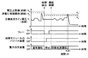
図6は、回生制動システムの処理内容を示すフローチャートである。また、図7は、回生制動システムの処理における電圧上限値や入力電圧と、リレー、故障であることが検出された電力変換モジュールのバイパス装置、及び、電力回生装置のオン・オフ状態との時間変化を示す図である。 FIG. 6 is a flowchart showing the processing contents of the regenerative braking system. Further, FIG. 7 shows the time between the voltage upper limit value and the input voltage in the processing of the regenerative braking system, the relay, the bypass device of the power conversion module detected as a failure, and the on / off state of the power regenerative device. It is a figure which shows the change.
図6において、制御装置41は、段数低減運転を行っていない通常運転中、まず、電力回生制御部421の故障検出部422によって故障した電力変換モジュールの検出を行い(ステップS100)、システム制御部411は、故障検出部422からの故障検出信号に基づいて、故障した電力変換モジュールがあるかどうかを判定する(ステップS110)。ステップS110での判定結果がNOの場合、すなわち、故障した電力変換モジュールが無い場合には、通常運転を継続しつつ判定結果がYESになるまでステップS100,S110の処理を繰り返す。なお、通常運転とは、電力回生装置21のN台全ての電力変換モジュール221~22Nを動作させる運転状態のことである。
In FIG. 6, the
このとき、図7に示すように、システム制御部411は、通常運転では、リレー制御部425を制御することによってリレー25を導通(オン)に制御し、モジュール制御部423を制御することによって電力回生装置21(ここでは、電力変換モジュール221~22N)を動作(オン)に制御する。なお、故障が検出された電力変換モジュールが無いため、バイパス制御部424によって短絡(オン)に制御するバイパス装置は無い。また、システム制御部411は、発電機制御部412及び電力消費装置制御部413を制御することによって、入力電圧Viが電圧設定値と一致するように、かつ、入力電力Viが電圧上限値Vmを超えないように主機発電機12及び電力消費装置15を制御する(期間(1)参照)。
At this time, as shown in FIG. 7, in the normal operation, the
また、ステップS110での判定結果がYESの場合、すなわち、故障検出部422からの故障検出信号に故障が検出された電力変換モジュールの情報が含まれている場合(以降、電力変換モジュール221の故障が検出された場合を例示して説明する)には、システム制御部411は、リレー制御部425を制御することによってリレー25を遮断(オフ)するように制御するとともに(ステップS120)、モジュール制御部423を制御することによって電力回生装置21の全ての電力変換モジュール221~22Nを停止(オフ)に制御し(ステップS130)、さらに、電圧上限値設定部414は、電圧上限値Vmを低減して新たな電圧上限値Vm2を設定して発電機制御部412及び電力消費装置制御部413に出力する(ステップS140)。このステップS120~S140の処理は、図7の故障検出のタイミングに対応する。なお、低減した電圧上限値Vm2の決定には種々の方法が考えられるが、少なくともVm>Vm2が成り立つように決定するものであり、例えば、電力変換モジュール221~22Nの一部(電力変換モジュール221)を停止する場合に、停止しない健全な電力変換モジュール222~22Nの1つ分に相当する電圧上限値が変わらないように電圧上限値Vm2を決定することが考えられる。より具体的には、N個の電力変換モジュール221~22Nの1個(例えば、電力変換モジュール221)を停止させる場合に、Vm/N=Vm2/(N-1)を満たすように電圧上限値Vm2を低減して設定する。
Further, when the determination result in step S110 is YES, that is, when the failure detection signal from the
続いて、システム制御部411は、バイパス制御部424を制御することによって故障が検出された電力変換モジュール221のバイパス装置231,241を短絡(オン)に制御する(ステップS150)。このステップS150の処理は、図7の故障検出~運転再開のタイミングに対応する。
Subsequently, the
続いて、システム制御部411は、リレー制御部425を制御することによってリレー25を導通(オン)に制御し(ステップS160)、モジュール制御部423を制御することによって健全な電力変換モジュール222~22Nを動作(オン)に制御し(ステップS170)、段数低減運転への移行を完了する。このステップS160,S170の処理は、図7の運転再開のタイミングに対応する。
Subsequently, the
段数低減運転においては、図7に示すように、入力電圧Viが電圧設定値と一致するように、かつ、入力電力Viが低減した電圧上限値Vm2を超えないように主機発電機12及び電力消費装置15を制御する(期間(2)参照)。
In the step reduction operation, as shown in FIG. 7, the
以上のように構成した本実施の形態における作用効果を説明する。 The action and effect in the present embodiment configured as described above will be described.
従来技術には、電力変換装置である単相インバータをモジュールとして捉え、複数のモジュールを直列接続することで1つの電力変換装置を構成するものがある。このような従来技術においては、故障や保守作業を行う必要が生じた場合に、各モジュールの出力にバイパス手段として接続された開閉器によって出力端子間をバイパス(短絡)状態にすることにより、一部のモジュールを停止させて残りのモジュールにより運転を継続可能としている。また、予備のモジュールを設けており、一部のモジュールを停止させる場合に予備のモジュールを用いることで、出力電圧を低下させずに運転を継続させている。 In the prior art, there is a method in which a single-phase inverter, which is a power conversion device, is regarded as a module, and a plurality of modules are connected in series to form one power conversion device. In such a conventional technique, when a failure or maintenance work needs to be performed, the output terminals are bypassed (short-circuited) by a switch connected to the output of each module as a bypass means. The module of the part is stopped and the operation can be continued by the remaining modules. Further, a spare module is provided, and by using the spare module when stopping a part of the modules, the operation is continued without lowering the output voltage.
しかしながら、上記従来技術においては、予備モジュールを設ける必要があるため、その分だけ電力回生装置全体が大型化してしまうという課題がある。また、各モジュールのバイパス手段(開閉器)を短絡して一部のモジュールを停止させ、残りのモジュールで運転を継続することも考えられるが、この場合には残りのモジュールに印加される電圧が増加してしまう。このため、各モジュールが電圧の増加に耐えられるよう、予め各モジュールの部品を高耐圧化したり、各モジュール内での絶縁距離を確保したりする必要が生じてしまう。したがって、この場合においても、モジュールが大型化してしまう、すなわち、電力回生装置全体が大型化してしまうという課題がある。 However, in the above-mentioned conventional technique, since it is necessary to provide a spare module, there is a problem that the entire power regenerative device becomes large by that amount. It is also conceivable to short-circuit the bypass means (switch) of each module to stop some modules and continue operation with the remaining modules. In this case, the voltage applied to the remaining modules is It will increase. Therefore, in order for each module to withstand an increase in voltage, it becomes necessary to increase the withstand voltage of each module component in advance and to secure an insulation distance within each module. Therefore, even in this case, there is a problem that the module becomes large, that is, the entire power regenerative device becomes large.
これに対して本実施の形態においては、エンジン11に接続される主機発電機12(第一の発電機)および補機発電機31(第二の発電機)と、主機発電機12に接続され、主機発電機12の出力を整流して直流電力として主機直流ライン16(第一の直流ライン)に出力する整流回路14(第一の整流回路)と、主機直流ライン16と走行モータ10L,10Rとの間に接続される走行モータ用のインバータ13L,13Rと、主機直流ライン16の電力を消費可能な電力消費装置15と、補機発電機31に接続され、補機発電機31の出力を整流して直流電力として補機直流ライン34(第二の直流ライン)に出力する整流回路32(第二の整流回路)と、補機直流ライン34に接続される補機装置33と、主機直流ライン16の電力を変換して補機直流ライン34に供給する電力回生装置21と、主機発電機12、電力消費装置15、および、電力回生装置21を制御する制御装置41とを備えた回生制動システムにおいて、電力回生装置は、主機直流ライン16からの電力を入力する入力部221a~22Naが直列接続された複数の電力変換モジュール221~22Nと、複数の電力変換モジュール221~22Nの入力部221a~22Naにそれぞれ接続され、入力部221a~22Naの正極端子(+)と負極端子(-)の間を短絡可能なバイパス装置231~23Nとを備え、制御装置41は、主機直流ライン16から電力回生装置21に入力される電圧が電圧上限値Vmを超えないように主機発電機12、電力消費装置15、及び、電力回生装置21を制御し、複数の電力変換モジュール221~22Nの一部を停止させる場合に、停止させる電力変換モジュールの入力部の正極端子(+)と負極端子(-)の間をバイパス装置によって短絡するとともに、電圧上限値Vmを低減するように構成したので、装置の大型化を防止しつつ運転の継続性を向上することができる。
On the other hand, in the present embodiment, the main engine generator 12 (first generator) and auxiliary generator 31 (second generator) connected to the
例えば、入力電圧Viが同じである場合を想定すると、段数低減運転時には通常運転時と比べて、各電力変換モジュール221~22Nの入力電圧が高くなる。すなわち、段数低減運転を想定して各電力変換モジュール221~22Nを高耐圧化する必要があり、これは電力回生装置21の大型化につながる。
For example, assuming that the input voltage Vi is the same, the input voltage of each
これに対して、本実施の形態においては、段数低減運転において入力電圧Viの上限値である電圧上限値VmをVm2に低減し、これに従って主機発電機12や電力消費装置15を制御する。すなわち、段数低減運転時では通常運転時と比べて、各電力変換モジュール221~22Nの入力電圧の最大値が上昇しないように、或いは、上昇量が小さくなるように制御する。したがって、各電力変換モジュール221~22Nを高耐圧化する必要はないため、小型・軽量の各電力変換モジュール221~22Nひいては電力回生装置21によって段数低減運転が可能となる。
On the other hand, in the present embodiment, the voltage upper limit value Vm, which is the upper limit value of the input voltage Vi, is reduced to Vm2 in the stage number reduction operation, and the
特に、電力変換モジュール221~22Nを構成するスイッチング素子は、その耐圧が低いほどオン抵抗が小さく、かつ、高速動作が可能であるため、電力損失をさらに低減することができる。また、高速動作が可能であれば、トランス271の動作周波数を高めることが可能となり、トランス271を小型・軽量化できる。トランス271は、寸法・重量の点で電力回生装置21に占める割合が大きいため、トランス271の小型・軽量化は電力回生装置21全体の小型・軽量化につながる。すなわち、本実施の形態のように、複数の電力変換モジュール221~22Nを直列に接続する構成によって、小型・軽量かつ省エネルギーであって、運転の継続性の高い電力回生装置を実現することができる。
In particular, the lower the withstand voltage of the switching elements constituting the
以上、本実施の形態においては、複数の電力変換モジュール221~22Nを直列に接続して構成した電力回生装置21を用いた回生制動システムによって、電気駆動作業車両の省エネルギー化を実現することができるとともに、故障などの理由によって一部の電力変換モジュールを停止させる場合に、残りの電力変換モジュールによって運転を継続させるので、装置の大型化を防止しつつ運転の継続性を向上することができる。
As described above, in the present embodiment, energy saving of the electric drive work vehicle can be realized by the regenerative braking system using the
なお、本実施の形態においては、各電力変換モジュール221~22Nの出力部221b~22Nbの正極の端子と負極の端子の間をそれぞれ短絡と開放とで切り換えることができるスイッチ様のバイパス装置241~24Nを用いる場合を例示して説明したが、バイパス装置241~24Nに代えて、各電力変換モジュール221~22Nの出力部221b~22Nbの正極(+)の端子とカソード端子を、負極(-)をアノード端子とそれぞれ接続したダイオードをバイパス装置として用いてもよい。また、電力変換モジュール221~22Nの出力部221b~22Nbにバイパス装置241~24Nを接続しない構成としてもよい。このような構成では、例えば、図3に例示する電力変換モジュール221のインバータ261のスイッチング素子が故障し、かつ、整流回路281には異常が無い場合には、整流回路281のダイオードが導通してバイパス装置としての機能を果たす。
In the present embodiment, the switch-
<第1の実施の形態の変形例>
第1の実施の形態の変形例を図8を参照しつつ説明する。本変形例では、第1の実施の形態との相違点についてのみ説明するものとし、図面における第1の実施の形態と同様の部材には同じ符号を付し、説明を省略する。
<Modified example of the first embodiment>
A modified example of the first embodiment will be described with reference to FIG. In this modification, only the differences from the first embodiment will be described, and the same members as those in the first embodiment in the drawings are designated by the same reference numerals, and the description thereof will be omitted.
本変形例は、補機直流ライン34の電圧が主機直流ライン16の電圧に比べて十分に低くなることに鑑み、第1の実施の形態の電力回生装置21における電力変換モジュール221~22Nの出力部221b~22Nbを並列接続するものである。
In this modification, in view of the fact that the voltage of the
図8は、本変形例に係るバイパス装置の一例を示す図である。 FIG. 8 is a diagram showing an example of a bypass device according to this modified example.
図8において、電力回生装置21Aは、入力部221a~22Naが主機直流ライン16の正負の2極の間に直列に接続され、出力部221b~22Nbが補機直流ライン34の正負の2極の間に並列に接続される複数(例えばN台:Nは2以上の正の整数)の電力変換モジュール221~22Nを備えている。
In FIG. 8, in the
図8においては、電力変換モジュール221のバイパス装置231をオン動作させて、入力部221aの正極端子(+)と負極端子(-)の間を短絡させた様子を例示している。この場合、電力変換モジュール221への入力電圧が0(ゼロ)となる。これにより、電力変換モジュール221~22Nのうち任意のものを直列接続から個別に電気的に外すことができる。また、電力変換モジュール222からの電流は、電力変換モジュール221をバイパス(迂回)して主機直流ライン16にそれぞれ供給される。
FIG. 8 illustrates a state in which the
本変形例のように各電力変換モジュール221~22Nの出力部221b~22Nbを並列に接続する場合、出力部221b~22Nbのバイパス装置は不要となる。また、各電力変換モジュール221~22Nで出力電圧は共通であり、通常運転時と段数低減運転時で出力電圧は変わらない。そのため、段数低減運転時に出力電圧を高くする制御も不要である。なお、各電力変換モジュール221~22Nの出力電流の和が電力回生装置21の出力電流となる。
When the
その他の構成は第1の実施の形態と同様である。 Other configurations are the same as in the first embodiment.
以上のように構成した本変形例においても第1の実施の形態と同様の効果を得ることができる。 In the present modification configured as described above, the same effect as that of the first embodiment can be obtained.
また、出力部のバイパス装置などの構成部材を削減することができる。 Further, it is possible to reduce the number of constituent members such as the bypass device of the output unit.
<第2の実施の形態>
第2の実施の形態を図9~図13を参照しつつ説明する。本実施の形態では、第1の実施の形態との相違点についてのみ説明するものとし、図面における第1の実施の形態と同様の部材には同じ符号を付し、説明を省略する。
<Second Embodiment>
The second embodiment will be described with reference to FIGS. 9 to 13. In the present embodiment, only the differences from the first embodiment will be described, and the same members as those in the first embodiment in the drawings are designated by the same reference numerals, and the description thereof will be omitted.
本実施の形態は、第1の実施の形態における電圧上限値Vmに代えて可変上限値として過電圧保護閾値Vpを用い、電力回生装置21の入力電圧Viが過電圧保護閾値Vpよりも高い場合に電力回生装置21を停止することによって、電力回生装置21に入力される電圧が可変上限値(過電圧保護閾値Vp)を超えないように制御するものである。
In this embodiment, an overvoltage protection threshold value Vp is used as a variable upper limit value instead of the voltage upper limit value Vm in the first embodiment, and power is generated when the input voltage Vi of the
図9は、本実施の形態に係る制御装置の処理機能を概略的に示す機能ブロック図である。 FIG. 9 is a functional block diagram schematically showing a processing function of the control device according to the present embodiment.
図9において、制御装置41Aは、システム制御部411A、発電機制御部412、電力消費装置制御部413、及び、電力回生制御部421を備えている。また、電力回生制御部421は、故障検出部422、モジュール制御部423、バイパス制御部424、リレー制御部425、及び、タイミング制御部426を備えている。
In FIG. 9, the
システム制御部411Aは、制御装置41Aの全体を制御するものであり、ダンプトラックの状態やオペレータの操作に基づいて、発電機制御部412及び電力消費装置制御部413で用いる電圧設定値を設定して出力する。また、システム制御部411は、電気駆動ダンプトラック100の状態やオペレータの操作、及び、故障検出部422からの電力回生装置21に関する故障検出信号(後述)に基づいて、電力回生制御部421のモジュール制御部423及びタイミング制御部426に制御信号を出力する。モジュール制御部423に出力する制御信号は、電力回生装置21の出力設定値である。また、タイミング制御部426に出力する制御信号は、電力回生装置21の電力変換モジュール221~22Nの稼動(オン)と停止(オフ)、及び、リレー25の導通(オン)と遮断(オフ)をそれぞれ切り換えるタイミングを制御するオン・オフタイミング信号である。
The
また、システム制御部411Aは、電圧検出器17で検出された主機直流ライン16の電圧(すなわち、電力回生装置21の入力電圧Vi)の検出値(電圧検出値)、及び、故障検出部422からの故障検出信号に基づいて、可変上限値である過電圧過保閾値(以降、電圧上限値Vpと定義する)を設定する。過電圧保護閾値Vpは、主機直流ライン16の電圧に対して電力回生装置21の入力部を保護する制御を行うかどうかを判定するための閾値である。システム制御部411Aは、電力回生装置21の入力電圧Viが過電圧保護閾値Vpよりも高い場合に、モジュール制御部423を制御することによって電力回生装置21(より具体的には、電力変換モジュール221~22Nのインバータ261~26N)を停止することで電力回生装置21に入力される電圧が可変上限値(過電圧保護閾値Vp)を超えないように制御する。
Further, the
発電機制御部412及び電力消費装置制御部413は、電圧検出器17で検出された主機直流ライン16の電圧(すなわち、電力回生装置21の入力電圧Vi)の検出値(電圧検出値)と、システム制御部411Aから出力される電圧設定値とに基づいて、主機発電機12及び電力消費装置15を制御する制御信号をそれぞれに出力し、主機発電機12及び電力消費装置15を制御することによって電力回生装置21の入力電圧Viを制御する。より具体的には、発電機制御部412及び電力消費装置制御部413は、入力電圧Viが電圧設定値と一致するように主機発電機12及び電力消費装置15を制御する。
The
以上のように構成した本実施の形態の回生制動システムでは、故障検出部422で故障であることが検出された電力変換モジュール(例えば、電力変換モジュール221)の運転を停止し、健全な電力変換モジュール(例えば、電力変換モジュール222~22N)のみを動作させる段数低減運転を行う。また、段数低減運転では、複数の電力変換モジュール221~22Nの一部(例えば、電力変換モジュール221)を停止させる場合に、停止させる電力変換モジュール221の入力部221aの正極端子と負極端子の間をバイパス装置231によって短絡するとともに、可変上限値である過電圧保護閾値Vpを低減する。
In the regenerative braking system of the present embodiment configured as described above, the operation of the power conversion module (for example, the power conversion module 221) detected to be a failure by the
以下、回生制動システムの段数低減運転を含む処理内容について詳細に説明する。 Hereinafter, the processing contents including the step reduction operation of the regenerative braking system will be described in detail.
図10は、回生制動システムの処理内容を示すフローチャートである。また、図11は、回生制動システムの処理における過電圧保護閾値や入力電圧と、リレー、故障であることが検出された電力変換モジュールのバイパス装置、及び、電力回生装置のオン・オフ状態との時間変化を示す図である。 FIG. 10 is a flowchart showing the processing contents of the regenerative braking system. Further, FIG. 11 shows the time between the overvoltage protection threshold and the input voltage in the processing of the regenerative braking system, the relay, the bypass device of the power conversion module detected as a failure, and the on / off state of the power regenerative device. It is a figure which shows the change.
図10において、制御装置41Aは、段数低減運転を行っていない通常運転中、まず、電圧検出器17で検出された入力電圧Viを取得し(ステップS200)、入力電圧Viが過電圧保護閾値Vpよりも高いかどうかを判定する(ステップS210)。ステップS210での判定結果がNOの場合には、電力回生装置21の全ての電力変換モジュール221~22Nを動作させ(ステップS212)、ステップS210での判定結果がYESの場合には、電力回生装置21の全ての電力変換モジュール221~22Nを停止させる(ステップS211)。
In FIG. 10, the
このとき、図11に示すように、システム制御部411Aは、通常運転では、リレー制御部425を制御することによってリレー25を導通(オン)に制御し、モジュール制御部423を制御することによって電力回生装置21(ここでは、電力変換モジュール221~22N)を動作(オン)に制御する。また、システム制御部411Aは、発電機制御部412及び電力消費装置制御部413を制御することによって、入力電圧Viが電圧設定値と一致するように主機発電機12及び電力消費装置15を制御する。また、入力電力Viが過電圧保護閾値Vpを超えた場合には、モジュール制御部423を制御することによって電力回生装置21を停止(オフ)に制御する(同様の制御を行う段数低減運転の期間(3)参照)。
At this time, as shown in FIG. 11, in normal operation, the
続いて、制御装置41Aは、電力回生制御部421の故障検出部422によって故障した電力変換モジュールの検出を行い(ステップS220)、システム制御部411Aは、故障検出部422からの故障検出信号に基づいて、故障した電力変換モジュールがあるかどうかを判定する(ステップS230)。ステップS230での判定結果がNOの場合、すなわち、故障した電力変換モジュールが無い場合には、判定結果がYESになるまで、通常運転を継続しつつステップS200~S230の処理を繰り返す。なお、通常運転とは、電力回生装置21のN台全ての電力変換モジュール221~22Nを動作させる運転状態のことである。
Subsequently, the
このとき、図11に示すように、システム制御部411Aは、通常運転では、リレー制御部425を制御することによってリレー25を導通(オン)に制御し、モジュール制御部423を制御することによって電力回生装置21(ここでは、電力変換モジュール221~22N)を動作(オン)に制御する。なお、故障が検出された電力変換モジュールが無いため、バイパス制御部424によって短絡(オン)に制御するバイパス装置は無い。また、システム制御部411Aは、発電機制御部412及び電力消費装置制御部413を制御することによって、入力電圧Viが電圧設定値と一致するように主機発電機12及び電力消費装置15を制御する。
At this time, as shown in FIG. 11, in normal operation, the
また、ステップS230での判定結果がYESの場合、すなわち、故障検出部422からの故障検出信号に故障が検出された電力変換モジュールの情報が含まれている場合(以降、電力変換モジュール221の故障が検出された場合を例示して説明する)には、システム制御部411Aは、リレー制御部425を制御することによってリレー25を遮断(オフ)するように制御するとともに(ステップS240)、モジュール制御部423を制御することによって電力回生装置21の全ての電力変換モジュール221~22Nを停止(オフ)に制御し(ステップS250)、さらに、過電圧保護閾値Vpを低減して新たな過電圧保護閾値Vp2を設定する(ステップS260)。このステップS240~S260の処理は、図11の故障検出のタイミングに対応する。なお、低減したか電圧保護閾値Vp2の決定には種々の方法が考えられるが、少なくともVp>Vp2が成り立つように決定するものであり、例えば、電力変換モジュール221~22Nの一部(電力変換モジュール221)を停止する場合に、停止しない健全な電力変換モジュール222~22Nの1つ分に相当する電圧保護閾値が変わらないように電圧保護閾値Vp2を決定することが考えられる。より具体的には、N個の電力変換モジュール221~22Nの1個(例えば、電力変換モジュール221)を停止させる場合に、Vp/N=Vp2/(N-1)を満たすように電圧上限値Vp2を低減して設定する。
Further, when the determination result in step S230 is YES, that is, when the failure detection signal from the
続いて、システム制御部411Aは、バイパス制御部424を制御することによって故障が検出された電力変換モジュール221のバイパス装置231,241を短絡(オン)に制御し(ステップS270)、システム制御部411Aは、リレー制御部425を制御することによってリレー25を導通(オン)に制御する(ステップS280)。このステップS270,280の処理は、図11の故障検出~運転再開の間のタイミングに対応する。
Subsequently, the
続いて、システム制御部411Aは、電圧検出器17で検出された入力電圧Viを取得し(ステップS290)、入力電圧Viが過電圧保護閾値Vpよりも高いかどうかを判定する(ステップS300)。ステップS300での判定結果がNOの場合には、判定結果がYESになるまで、ステップS290,S300の処理を繰り返す。
Subsequently, the
また、ステップS300での判定結果がNOの場合には、システム制御部411Aは、モジュール制御部423を制御することによって健全な電力変換モジュール222~22Nを動作(オン)に制御し(ステップS301)、段数低減運転への移行を完了する。このステップS301の処理は、図11の運転再開のタイミングに対応する。
If the determination result in step S300 is NO, the
段数低減運転においては、図11に示すように、入力電圧Viが電圧設定値と一致するように制御する。また、入力電力Viが過電圧保護閾値Vpを超えた場合には、モジュール制御部423を制御することによって電力回生装置21を停止(オフ)に制御する(期間(3)参照)。
In the step reduction operation, as shown in FIG. 11, the input voltage Vi is controlled so as to match the voltage set value. When the input power Vi exceeds the overvoltage protection threshold value Vp, the
ここで、電力変換モジュールのインバータを構成するスイッチング素子の耐圧と素子電圧との関係について説明する。 Here, the relationship between the withstand voltage of the switching element constituting the inverter of the power conversion module and the element voltage will be described.
図12は、電力変換モジュールが動作している場合のスイッチング素子の素子電圧の時間変化を示す図である。また、図13は、電力変換モジュールが停止している場合のスイッチング素子の素子電圧の時間変化を示す図である。なお、ここでは、電力変換モジュール221のインバータ261のスイッチング素子について例示して説明する。
FIG. 12 is a diagram showing a time change of the element voltage of the switching element when the power conversion module is operating. Further, FIG. 13 is a diagram showing a time change of the element voltage of the switching element when the power conversion module is stopped. Here, the switching element of the
図12に示すように、電力変換モジュール221が電力変換器としての動作を行っている場合、インバータ261のスイッチング素子はオンとオフを周期的に繰り返し、したがって、スイッチング素子の素子電圧は周期的に変化する。例えば、スイッチング素子がオンの状態では、素子電圧はほぼ0(ゼロ)であり、スイッチング素子がオフの状態では、素子電圧と電力変換モジュール221の入力電圧がほぼ等しくなる。なお、図12では、電力回生装置21が通常運転しており、各電力変換モジュール221~22Nの入力電圧がVi/Nであることを想定している。また、スイッチング素子がターンオフする場合にはサージ電圧が発生し、素子電圧は過渡的にVi/Nより高くなる。破線で示したスイッチング素子の耐圧は、このサージ電圧も考慮した上で設定される。
As shown in FIG. 12, when the
一方、図13に示すように、電力変換モジュール221が停止している場合、スイッチング素子は常にオフであるため、素子電圧は一定であり、スイッチングに伴うサージ電圧は発生しない。スイッチング素子が2個のスイッチング素子を直列に接続した構成である場合、電力変換モジュール221の入力電圧が2個のスイッチング素子で分圧される。図13では、2個のスイッチング素子の素子電圧がバランスしていると仮定し、電圧値をVi/(2N)とした。図13から分かるように、電力変換モジュール221が停止していれば、素子電圧の耐圧に対する余裕が大きくなる。
On the other hand, as shown in FIG. 13, when the
その他の構成は第1の実施の形態と同様である。 Other configurations are the same as in the first embodiment.
以上のように構成した本実施の形態においても第1の実施の形態と同様の効果を得ることができる。 Also in the present embodiment configured as described above, the same effect as that of the first embodiment can be obtained.
また、段数低減運転時では通常運転時に比べて電力変換モジュール221~22Nの入力電圧が高くなる。そこで、本実施の形態においては、段数低減運転において過電圧保護閾値Vpを低減し、より低い入力電圧Viにおいて電力変換モジュール221~22Nを停止させるように制御する。これにより、モジュールを高耐圧化することなく、小型・軽量のモジュールひいては電力回生装置21によって段数低減運転が可能となる。さらに、第1の実施の形態においては、段数低減運転時に電圧上限値Vmを低減するため、走行モータ10L,10Rの駆動可能範囲が制限されていたが、本実施の形態においては、入力電圧Viの上限値を低減しないので、走行モータ10L,10Rの駆動可能範囲を制限することなく段数低減運転を行うことができる。
Further, in the operation with a reduced number of stages, the input voltage of the
なお、本実施の形態においては、通常運転時と段数低減運転時の両方において、入力電圧Viが過電圧保護閾値Vp,Vp2より大きい場合に電力回生装置21を停止するよう制御する場合を例示して説明したが、例えば、段数低減運転時のみにおいて、入力電圧Viが過電圧保護閾値Vp,Vp2より大きい場合に電力回生装置21を停止するよう制御するように構成してもよい。これは、通常運転時の過電圧保護閾値Vpを、取り得る入力電圧Viの範囲より高くすることで実現することができる。また、段数低減運転時に動作させる電力変換モジュールの台数によって過電圧保護閾値を可変させるように構成してもよい。
In the present embodiment, a case where the
<その他の実施の形態>
本発明は上記の実施の形態に限定されるものではなく、その要旨を逸脱しない範囲内の様々な変形例や組み合わせが含まれる。例えば、第1の実施の形態において示した電圧上限値Vm,Vm2による主機直流ライン16の電圧Viの制御と、第2の実施の形態において示した過電圧保護閾値Vp,Vp2による電力回生装置21の停止制御とを同時に行うことができる。
<Other embodiments>
The present invention is not limited to the above-described embodiment, and includes various modifications and combinations within a range that does not deviate from the gist thereof. For example, the control of the voltage Vi of the main
図14は、電圧上限値及び過電圧保護閾値を用いた制御を行う場合の回生制動システムの処理における電圧上限値や入力電圧と、リレー、故障であることが検出された電力変換モジュールのバイパス装置、及び、電力回生装置のオン・オフ状態との時間変化を示す図である。 FIG. 14 shows the voltage upper limit and the input voltage in the processing of the regenerative braking system when the control is performed using the voltage upper limit and the overvoltage protection threshold, the relay, and the bypass device of the power conversion module detected to be a failure. Further, it is a figure which shows the time change with the on / off state of a power regeneration apparatus.
図14に示すように、通常運転時の電圧上限値Vmは過電圧保護閾値Vpより高く設定され、かつ、段数低減運転時の電圧上限値Vm2は過電圧保護閾値Vp2より高く設定される。図14における、段数低減運転時の期間(4)では、入力電圧Viが電圧上限値Vm2を超えないように制御されており、かつ、入力電圧Viが過電圧保護閾値Vp2より高いため電力回生装置21を停止させる制御を行っている。
As shown in FIG. 14, the voltage upper limit value Vm during normal operation is set higher than the overvoltage protection threshold value Vp, and the voltage upper limit value Vm2 during the stage reduction operation is set higher than the overvoltage protection threshold value Vp2. In the period (4) during the stage reduction operation in FIG. 14, the input voltage Vi is controlled so as not to exceed the voltage upper limit value Vm2, and the input voltage Vi is higher than the overvoltage protection threshold value Vp2, so that the
以上のような構成においては、電力変換モジュールの耐圧に基づいて入力電圧Viの上限を設定できるようになり、より信頼性の高い回生制動システムを実現することができる。 In the above configuration, the upper limit of the input voltage Vi can be set based on the withstand voltage of the power conversion module, and a more reliable regenerative braking system can be realized.
次に上記の各実施の形態の特徴について説明する。 Next, the features of each of the above embodiments will be described.
(1)上記の実施の形態では、エンジン11に接続される第一の発電機(例えば、主機発電機12)および第二の発電機(例えば、補機発電機31)と、前記第一の発電機に接続され、前記第一の発電機の出力を整流して直流電力として第一の直流ライン(例えば、主機直流ライン16)に出力する第一の整流回路(例えば、整流回路14)と、前記第一の直流ラインと走行モータ10L,10Rとの間に接続される走行モータ用のインバータ13L,13Rと、前記第一の直流ラインに接続され、前記第一の直流ラインの電力を消費可能な電力消費装置15と、前記第二の発電機に接続され、前記第二の発電機の出力を整流して直流電力として第二の直流ライン(例えば、補機直流ライン34)に出力する第二の整流回路(例えば、整流回路32)と、前記第二の直流ラインに接続される補機装置33と、前記第一の直流ラインの電力を変換して前記第二の直流ラインに供給する電力回生装置21と、前記第一の発電機、前記電力消費装置、および、前記電力回生装置を制御する制御装置41,41Aとを備えた回生制動システムにおいて、前記電力回生装置は、前記第一の直流ラインからの電力を入力する入力部221a~22Naが直列接続された複数の電力変換モジュール221~22Nと、前記複数の電力変換モジュールの入力部にそれぞれ接続され、前記入力部の正極端子(+)と負極端子(-)の間を個別に短絡可能な第一のバイパス装置群(例えば、バイパス装置231~23N)とを備え、前記制御装置は、前記第一の直流ラインから前記電力回生装置に入力される電圧Viが前記複数の電力変換モジュールの耐電圧特性の合計に基づく可変上限値(例えば、電圧上限値Vm、過電圧保護閾値Vp)を超えないように前記第一の発電機、前記電力消費装置、及び、前記電力回生装置を制御し、前記複数の電力変換モジュールの一部を停止させる場合に、停止させる電力変換モジュールの入力部の正極端子と負極端子の間を前記第一のバイパス装置群によって短絡するとともに、前記可変上限値を前記複数の電力変換モジュールのうち停止させる前記一部の電力変換モジュールの耐電圧特性に応じて低減するものとした。
(1) In the above embodiment, the first generator (for example, the main engine generator 12) and the second generator (for example, the auxiliary generator generator 31) connected to the
これにより、装置の大型化を防止しつつ運転の継続性を向上することができる。 As a result, it is possible to improve the continuity of operation while preventing the device from becoming large in size.
(2)また、上記の実施の形態では、(1)の回生制動システムにおいて、前記可変上限値は、前記第一の直流ライン(例えば、主機直流ライン16)の電圧Viに係る電圧上限値Vmを含み、前記制御装置41は、前記第一の直流ラインの電圧が前記電圧上限値を超えないように前記第一の発電機(例えば、主機発電機12)および前記電力消費装置15を制御することにより、前記電力回生装置21に入力される電圧が可変上限値を超えないように制御するものとした。
(2) Further, in the above embodiment, in the regenerative braking system of (1), the variable upper limit value is the voltage upper limit value Vm related to the voltage Vi of the first DC line (for example, the main engine DC line 16). The
(3)また、上記の実施の形態では、(1)又は(2)の回生制動システムにおいて、前記可変上限値は、前記電力回生装置21に入力される電圧Viに係る過電圧保護閾値Vpを含み、前記複数の電力変換モジュール221~22Nは、前記入力部221a~22Naから入力される電力の変換に供される少なくとも一つのスイッチング素子をそれぞれ備え、前記制御装置41Aは、前記第一の直流ライン(例えば、主機直流ライン16)の電圧Viが前記過電圧保護閾値に達したときに前記複数の電力変換モジュールの全てのスイッチング素子の動作を停止することにより、前記電力回生装置に入力される電圧が可変上限値を超えないように制御するものとした。
(3) Further, in the above embodiment, in the regenerative braking system of (1) or (2), the variable upper limit value includes an overvoltage protection threshold Vp related to the voltage Vi input to the
(4)また、上記の実施の形態では、(2)の回生制動システムにおいて、前記可変上限値は、前記電力回生装置21に入力される電圧に係る、前記電圧上限値Vmよりも低く設定された過電圧保護閾値Vpを含み、前記複数の電力変換モジュール221~22Nは、前記入力部221a~22Naから入力される電力の変換に供される少なくとも一つのスイッチング素子をそれぞれ備え、前記制御装置41,41Aは、前記第一の直流ライン(主機直流ライン16)の電圧Viが前記過電圧保護閾値に達したときに前記複数の電力変換モジュールの全てのスイッチング素子の動作を停止することにより、前記電力回生装置に入力される電圧が可変上限値(例えば、電圧上限値Vp、過電圧保護閾値Vp)を超えないように制御するものとした。
(4) Further, in the above embodiment, in the regenerative braking system of (2), the variable upper limit value is set lower than the voltage upper limit value Vm related to the voltage input to the
(5)また、上記の実施の形態では、(1)の回生制動システムにおいて、前記複数の電力変換モジュール221~22Nの前記第二の直流ライン(例えば、補機直流ライン34)に電力を出力する出力部221b~22Nbは直列接続されており、前記電力回生装置21は、前記複数の電力変換モジュールの出力部にそれぞれ接続され、前記出力部の正極端子(+)と負極端子(-)の間を短絡可能な第二のバイパス装置群(例えば、バイパス装置241~24N)を備えたものとした。
(5) Further, in the above embodiment, in the regenerative braking system of (1), power is output to the second DC line (for example, auxiliary DC line 34) of the plurality of
(6)また、上記の実施の形態では、(1)の回生制動システムにおいて、前記複数の電力変換モジュール221~22Nの前記第二の直流ライン(例えば、補機直流ライン34)に電力を出力する出力部221b~22Nbが並列接続されたものとした。
(6) Further, in the above embodiment, in the regenerative braking system of (1), power is output to the second DC line (for example, auxiliary DC line 34) of the plurality of
(7)また、上記の実施の形態では、(1)の回生制動システムにおいて、前記制御装置41,41Aは、前記複数の電力変換モジュールの一部を停止させる場合の停止対象ではない電力変換モジュールの台数が多いほど、前記可変上限値(例えば、電圧上限値Vm、過電圧保護閾値Vp)を高くするものとした。
(7) Further, in the above embodiment, in the regenerative braking system of (1), the
(8)また、上記の実施の形態では、(1)の回生制動システムにおいて、第一の直流ライン(主機直流ライン16)から前記電力回生装置21に入力される電力を遮断可能なリレー25を備え、前記制御装置41,41Aは、前記複数の電力変換モジュールの一部を停止させる場合に、前記リレーによって前記電力回生装置に入力される電力を遮断し、かつ、前記複数の電力変換モジュールを全て停止させ、かつ、前記可変上限値(例えば、電圧上限値Vm、過電圧保護閾値Vp)を低減した後に、停止させる前記電力変換モジュールの入力部の正極端子(+)と負極端子(-)の間を前記第一のバイパス装置群(例えば、バイパス装置231~23N)によって短絡し、停止させる前記電力変換モジュールの入力部の正極端子と負極端子の間を短絡した後に、前記リレーによって前記電力回生装置に入力される電力を導通し、前記電力回生装置に入力される電力を導通した後に、停止対象ではない電力変換モジュールの運転を再開するものとした。
(8) Further, in the above embodiment, in the regenerative braking system of (1), a
(9)また、上記の実施の形態では、電気駆動作業車両において、エンジン11と、(1)の回生制動システムと、前記回生制動システムの前記第一の発電機(例えば、主機発電機12)から前記第一の整流回路(例えば、第一の整流回路14)を介して前記第一の直流ライン(例えば、主機直流ライン16)に出力される電力で動作するとともに、前記第一の直流ラインに回生電力を出力する走行モータ10L,10Rにより駆動される駆動輪3L,3Rとを備えるものとした。
(9) Further, in the above-described embodiment, in the electrically driven work vehicle, the
(10)また、上記の実施の形態では、(1)の回生制動システムにおいて、前記複数の電力変換モジュールは耐電圧特性において同等の特性を有し、これらの一部を停止させる場合は、停止させる前記一部の電力変換モジュールの個数に応じて前記可変上限値を低減するものとした。 (10) Further, in the above embodiment, in the regenerative braking system of (1), the plurality of power conversion modules have the same withstand voltage characteristics, and when a part of them is stopped, the power conversion modules are stopped. The variable upper limit value is reduced according to the number of some of the power conversion modules to be generated.
<付記>
なお、本発明は上記の実施の形態に限定されるものではなく、その要旨を逸脱しない範囲内の様々な変形例や組み合わせが含まれる。また、本発明は、上記の実施の形態で説明した全ての構成を備えるものに限定されず、その構成の一部を削除したものも含まれる。また、上記の各構成、機能等は、それらの一部又は全部を、例えば集積回路で設計する等により実現してもよい。また、上記の各構成、機能等は、プロセッサがそれぞれの機能を実現するプログラムを解釈し、実行することによりソフトウェアで実現してもよい。
<Additional notes>
The present invention is not limited to the above-described embodiment, and includes various modifications and combinations within a range that does not deviate from the gist thereof. Further, the present invention is not limited to the one including all the configurations described in the above-described embodiment, and includes the one in which a part of the configurations is deleted. Further, each of the above configurations, functions and the like may be realized by designing a part or all of them by, for example, an integrated circuit. Further, each of the above configurations, functions, and the like may be realized by software by the processor interpreting and executing a program that realizes each function.
1…車体フレーム、2L,2R…従動輪(前輪)、3aL,3aR…減速機、3L,3R…駆動輪(後輪)、4…運転室、5…荷台(ベッセル)、5a…ピン結合部、6…ホイストシリンダ、7…グリッドボックス、8…コントロールキャビネット、9…燃料タンク、10L,10R…走行モータ、11…エンジン、12…主機発電機、13L,13R…インバータ、14…整流回路、15…電力消費装置、16…主機直流ライン、17…電圧検出器、21,21A…電力回生装置、221~22N…電力変換モジュール、221a~22Na…入力部、221b~22Nb…出力部、231~23N,241~24N…バイパス装置、25…リレー、26N…インバータ、31…補機発電機、32…整流回路、33…補機装置、34…補機直流ライン、41,41A…制御装置、100…電気駆動ダンプトラック、151…抵抗、152…スイッチング素子、153…ダイオード、261…インバータ、271…トランス、281…整流回路、411,411A…システム制御部、412…発電機制御部、413…電力消費装置制御部、414…電圧上限値設定部、421…電力回生制御部、422…故障検出部、423…モジュール制御部、424…バイパス制御部、425…リレー制御部、426…タイミング制御部 1 ... Body frame, 2L, 2R ... Driven wheels (front wheels), 3aL, 3aR ... Reducer, 3L, 3R ... Drive wheels (rear wheels), 4 ... Driver's cab, 5 ... Loading platform (Vessel), 5a ... Pin joint , 6 ... Hoist cylinder, 7 ... Grid box, 8 ... Control cabinet, 9 ... Fuel tank, 10L, 10R ... Travel motor, 11 ... Engine, 12 ... Main generator generator, 13L, 13R ... Inverter, 14 ... Rectifier circuit, 15 ... Power consuming device, 16 ... Main engine DC line, 17 ... Voltage detector, 21,21A ... Power regeneration device, 221 to 22N ... Power conversion module, 221a to 22Na ... Input unit, 221b to 22Nb ... Output unit, 231 to 23N , 241-24N ... Bypass device, 25 ... Relay, 26N ... Inverter, 31 ... Auxiliary generator, 32 ... Rectifier circuit, 33 ... Auxiliary device, 34 ... Auxiliary DC line, 41, 41A ... Control device, 100 ... Electric drive dump truck, 151 ... Resistance, 152 ... Switching element, 153 ... Diode, 261 ... Inverter, 271 ... Transformer, 281 ... Rectifier circuit, 411,411A ... System control unit, 412 ... Generator control unit, 413 ... Power consumption Device control unit, 414 ... Voltage upper limit value setting unit, 421 ... Power regeneration control unit, 422 ... Failure detection unit, 423 ... Module control unit, 424 ... Bypass control unit, 425 ... Relay control unit, 426 ... Timing control unit
Claims (10)
前記第一の発電機に接続され、前記第一の発電機の出力を整流して直流電力として第一の直流ラインに出力する第一の整流回路と、
前記第一の直流ラインと走行モータとの間に接続されるインバータと、
前記第一の直流ラインに接続され、前記第一の直流ラインの電力を消費可能な電力消費装置と、
前記第二の発電機に接続され、前記第二の発電機の出力を整流して直流電力として第二の直流ラインに出力する第二の整流回路と、
前記第二の直流ラインに接続される補機装置と、
前記第一の直流ラインの電力を変換して前記第二の直流ラインに供給する電力回生装置と、
前記第一の発電機、前記電力消費装置、および、前記電力回生装置を制御する制御装置と
を備えた回生制動システムにおいて、
前記電力回生装置は、
前記第一の直流ラインからの電力を入力する入力部が直列接続された複数の電力変換モジュールと、
前記複数の電力変換モジュールの入力部にそれぞれ接続され、前記入力部の正極端子と負極端子の間を個別に短絡可能な第一のバイパス装置群とを備え、
前記制御装置は、
前記第一の直流ラインから前記電力回生装置に入力される電圧が前記複数の電力変換モジュールの耐電圧特性の合計に基づく可変上限値を超えないように前記第一の発電機、前記電力消費装置、及び、前記電力回生装置を制御し、
前記複数の電力変換モジュールの一部を停止させる場合に、停止させる電力変換モジュールの入力部の正極端子と負極端子の間を前記第一のバイパス装置群によって短絡するとともに、前記可変上限値を前記複数の電力変換モジュールのうち停止させる前記一部の電力変換モジュールの耐電圧特性に応じて低減することを特徴とする回生制動システム。 The first and second generators connected to the engine,
A first rectifier circuit that is connected to the first generator, rectifies the output of the first generator, and outputs it as DC power to the first DC line.
An inverter connected between the first DC line and the traveling motor,
A power consuming device connected to the first DC line and capable of consuming the power of the first DC line,
A second rectifier circuit that is connected to the second generator and rectifies the output of the second generator and outputs it as DC power to the second DC line.
Auxiliary equipment connected to the second DC line,
A power regenerative device that converts the power of the first DC line and supplies it to the second DC line.
In a regenerative braking system including the first generator, the power consuming device, and a control device for controlling the power regenerating device.
The power regenerative device is
A plurality of power conversion modules in which input units for inputting power from the first DC line are connected in series, and
It is provided with a first bypass device group which is connected to each input unit of the plurality of power conversion modules and can individually short-circuit between the positive electrode terminal and the negative electrode terminal of the input unit.
The control device is
The first generator and the power consuming device so that the voltage input from the first DC line to the power regenerating device does not exceed the variable upper limit value based on the total withstand voltage characteristics of the plurality of power conversion modules. , And control the power regenerator,
When a part of the plurality of power conversion modules is stopped, the positive electrode terminal and the negative electrode terminal of the input portion of the power conversion module to be stopped are short-circuited by the first bypass device group, and the variable upper limit value is set. A regenerative braking system characterized in that the voltage is reduced according to the withstand voltage characteristics of some of the power conversion modules to be stopped among the plurality of power conversion modules.
前記可変上限値は、前記第一の直流ラインの電圧に係る電圧上限値を含み、
前記制御装置は、前記第一の直流ラインの電圧が前記電圧上限値を超えないように前記第一の発電機および前記電力消費装置を制御することにより、前記電力回生装置に入力される電圧が可変上限値を超えないように制御することを特徴とする回生制動システム。 In the regenerative braking system according to claim 1,
The variable upper limit value includes a voltage upper limit value related to the voltage of the first DC line.
The control device controls the first generator and the power consuming device so that the voltage of the first DC line does not exceed the voltage upper limit value, so that the voltage input to the power regeneration device can be increased. A regenerative braking system characterized in that it is controlled so as not to exceed the variable upper limit value.
前記可変上限値は、前記電力回生装置に入力される電圧に係る過電圧保護閾値を含み、
前記複数の電力変換モジュールは、前記入力部から入力される電力の変換に供される少なくとも一つのスイッチング素子をそれぞれ備え、
前記制御装置は、前記第一の直流ラインの電圧が前記過電圧保護閾値に達したときに前記複数の電力変換モジュールの全てのスイッチング素子の動作を停止することにより、前記電力回生装置に入力される電圧が可変上限値を超えないように制御することを特徴とする回生制動システム。 In the regenerative braking system according to claim 1 or 2.
The variable upper limit value includes an overvoltage protection threshold value related to the voltage input to the power regenerative device.
Each of the plurality of power conversion modules includes at least one switching element used for converting power input from the input unit.
The control device is input to the power regeneration device by stopping the operation of all the switching elements of the plurality of power conversion modules when the voltage of the first DC line reaches the overvoltage protection threshold. A regenerative braking system characterized by controlling the voltage so that it does not exceed the variable upper limit.
前記可変上限値は、前記電力回生装置に入力される電圧に係る、前記電圧上限値よりも低く設定された過電圧保護閾値を含み、
前記複数の電力変換モジュールは、前記入力部から入力される電力の変換に供される少なくとも一つのスイッチング素子をそれぞれ備え、
前記制御装置は、前記第一の直流ラインの電圧が前記過電圧保護閾値に達したときに前記複数の電力変換モジュールの全てのスイッチング素子の動作を停止することにより、前記電力回生装置に入力される電圧が可変上限値を超えないように制御することを特徴とする回生制動システム。 In the regenerative braking system according to claim 2,
The variable upper limit value includes an overvoltage protection threshold set lower than the voltage upper limit value related to the voltage input to the power regenerative device.
Each of the plurality of power conversion modules includes at least one switching element used for converting power input from the input unit.
The control device is input to the power regeneration device by stopping the operation of all the switching elements of the plurality of power conversion modules when the voltage of the first DC line reaches the overvoltage protection threshold. A regenerative braking system characterized by controlling the voltage so that it does not exceed the variable upper limit.
前記複数の電力変換モジュールの前記第二の直流ラインに電力を出力する出力部は直列接続されており、
前記電力回生装置は、前記複数の電力変換モジュールの出力部にそれぞれ接続され、前記出力部の正極端子と負極端子の間を短絡可能な第二のバイパス装置群を備えたことを特徴とする回生制動システム。 In the regenerative braking system according to claim 1,
The output units that output power to the second DC line of the plurality of power conversion modules are connected in series.
The power regeneration device is characterized by being connected to each output unit of the plurality of power conversion modules and provided with a second bypass device group capable of short-circuiting between the positive electrode terminal and the negative electrode terminal of the output unit. Braking system.
前記複数の電力変換モジュールの前記第二の直流ラインに電力を出力する出力部が並列接続されたことを特徴とする回生制動システム。 In the regenerative braking system according to claim 1,
A regenerative braking system characterized in that output units that output electric power are connected in parallel to the second DC line of the plurality of electric power conversion modules.
前記制御装置は、前記複数の電力変換モジュールの一部を停止させる場合の停止対象ではない電力変換モジュールの台数が多いほど、前記可変上限値を高くすることを特徴とする電動車両の回生制動システム。 In the regenerative braking system according to claim 1,
The control device is a regenerative braking system for an electric vehicle, characterized in that the variable upper limit value is increased as the number of power conversion modules that are not to be stopped when a part of the plurality of power conversion modules is stopped increases. ..
第一の直流ラインから前記電力回生装置に入力される電力を遮断可能なリレーを備え、
前記制御装置は、
前記複数の電力変換モジュールの一部を停止させる場合に、
前記リレーによって前記電力回生装置に入力される電力を遮断し、かつ、前記複数の電力変換モジュールを全て停止させ、かつ、前記可変上限値を低減した後に、停止させる前記電力変換モジュールの入力部の正極端子と負極端子の間を前記第一のバイパス装置群によって短絡し、
停止させる前記電力変換モジュールの入力部の正極端子と負極端子の間を短絡した後に、前記リレーによって前記電力回生装置に入力される電力を導通し、
前記電力回生装置に入力される電力を導通した後に、停止対象ではない電力変換モジュールの運転を再開することを特徴とする回生制動システム。 In the regenerative braking system according to claim 1,
A relay capable of cutting off the power input to the power regenerator from the first DC line is provided.
The control device is
When stopping a part of the plurality of power conversion modules,
The input unit of the power conversion module that shuts off the power input to the power regenerator by the relay, stops all the plurality of power conversion modules, reduces the variable upper limit value, and then stops. A short circuit is made between the positive electrode terminal and the negative electrode terminal by the first bypass device group.
After short-circuiting between the positive electrode terminal and the negative electrode terminal of the input portion of the power conversion module to be stopped, the power input to the power regeneration device by the relay is conducted to conduct the power.
A regenerative braking system characterized in that, after conducting power input to the power regenerative device, the operation of a power conversion module that is not a stop target is restarted.
請求項1記載の回生制動システムと、
前記回生制動システムの前記第一の発電機から前記第一の整流回路を介して前記第一の直流ラインに出力される電力で動作するとともに、前記第一の直流ラインに回生電力を出力する走行モータにより駆動される駆動輪と
を備えたことを特徴とする電気駆動作業車両。 With the engine
The regenerative braking system according to claim 1 and
Traveling that operates with the electric power output from the first generator of the regenerative braking system to the first DC line via the first rectifier circuit and outputs the regenerative power to the first DC line. An electrically driven work vehicle characterized by having drive wheels driven by a motor.
前記複数の電力変換モジュールは耐電圧特性において同等の特性を有し、これらの一部を停止させる場合は、停止させる前記一部の電力変換モジュールの個数に応じて前記可変上限値を低減することを特徴とする回生制動システム。 In the regenerative braking system according to claim 1,
The plurality of power conversion modules have the same withstand voltage characteristics, and when a part of them is stopped, the variable upper limit value is reduced according to the number of the part of the power conversion modules to be stopped. A regenerative braking system featuring.
Priority Applications (5)
| Application Number | Priority Date | Filing Date | Title |
|---|---|---|---|
| JP2018228377A JP7102053B2 (en) | 2018-12-05 | 2018-12-05 | Regenerative braking system and electrically driven work vehicle using it |
| US17/293,949 US11834033B2 (en) | 2018-12-05 | 2019-11-27 | Regenerative braking system and electrically-driven work vehicle using regenerative braking system |
| CN201980074568.9A CN113015663B (en) | 2018-12-05 | 2019-11-27 | Regenerative braking system and electric drive work vehicle using same |
| PCT/JP2019/046336 WO2020116272A1 (en) | 2018-12-05 | 2019-11-27 | Regenerative braking system and electrically driven work vehicle using same |
| EP19893216.2A EP3892507A4 (en) | 2018-12-05 | 2019-11-27 | Regenerative braking system and electrically driven work vehicle using same |
Applications Claiming Priority (1)
| Application Number | Priority Date | Filing Date | Title |
|---|---|---|---|
| JP2018228377A JP7102053B2 (en) | 2018-12-05 | 2018-12-05 | Regenerative braking system and electrically driven work vehicle using it |
Publications (2)
| Publication Number | Publication Date |
|---|---|
| JP2020090188A JP2020090188A (en) | 2020-06-11 |
| JP7102053B2 true JP7102053B2 (en) | 2022-07-19 |
Family
ID=70974234
Family Applications (1)
| Application Number | Title | Priority Date | Filing Date |
|---|---|---|---|
| JP2018228377A Active JP7102053B2 (en) | 2018-12-05 | 2018-12-05 | Regenerative braking system and electrically driven work vehicle using it |
Country Status (5)
| Country | Link |
|---|---|
| US (1) | US11834033B2 (en) |
| EP (1) | EP3892507A4 (en) |
| JP (1) | JP7102053B2 (en) |
| CN (1) | CN113015663B (en) |
| WO (1) | WO2020116272A1 (en) |
Families Citing this family (7)
| Publication number | Priority date | Publication date | Assignee | Title |
|---|---|---|---|---|
| JP7102053B2 (en) * | 2018-12-05 | 2022-07-19 | 日立建機株式会社 | Regenerative braking system and electrically driven work vehicle using it |
| JP6923722B1 (en) * | 2020-07-28 | 2021-08-25 | 日立建機株式会社 | Drive system |
| JP7053919B1 (en) | 2021-03-26 | 2022-04-12 | 日立建機株式会社 | Dump truck drive system |
| CN113370957B (en) * | 2021-08-16 | 2021-11-02 | 北京晟科网鼎网络科技有限公司 | Braking force distribution control method, braking system and braking method for electric loader |
| JP7198330B1 (en) | 2021-10-25 | 2022-12-28 | 日立建機株式会社 | Dump truck drive system |
| JP7209798B1 (en) | 2021-10-28 | 2023-01-20 | 日立建機株式会社 | power generation system |
| US12224656B2 (en) * | 2023-02-08 | 2025-02-11 | Ravisekhar Nadimpalli Raju | Modular power converter with bypassable isolated modules |
Citations (2)
| Publication number | Priority date | Publication date | Assignee | Title |
|---|---|---|---|---|
| JP2008113548A (en) | 2006-10-04 | 2008-05-15 | Denso Corp | Two transformer dc-dc converter |
| JP2018152172A (en) | 2017-03-10 | 2018-09-27 | 本田技研工業株式会社 | Electrical power system |
Family Cites Families (26)
| Publication number | Priority date | Publication date | Assignee | Title |
|---|---|---|---|---|
| WO2005118329A1 (en) * | 2004-05-27 | 2005-12-15 | Siemens Energy & Automation, Inc. | System and method for cooling the power electronics of a mining machine |
| JP4747968B2 (en) * | 2006-06-30 | 2011-08-17 | トヨタ自動車株式会社 | Motor drive device |
| US7746670B2 (en) | 2006-10-04 | 2010-06-29 | Denso Corporation | Dual-transformer type of DC-to-DC converter |
| JP4179381B2 (en) * | 2007-01-25 | 2008-11-12 | トヨタ自動車株式会社 | Electric vehicle |
| JP2008252966A (en) * | 2007-03-29 | 2008-10-16 | Matsushita Electric Ind Co Ltd | Motor drive device |
| JP2009033943A (en) * | 2007-07-31 | 2009-02-12 | Meidensha Corp | Direct high voltage inverter apparatus |
| JP4240149B1 (en) * | 2008-02-14 | 2009-03-18 | トヨタ自動車株式会社 | Motor drive device and hybrid drive device |
| JP5229389B2 (en) * | 2009-06-10 | 2013-07-03 | トヨタ自動車株式会社 | Electric vehicle power supply system and control method thereof |
| US8773065B2 (en) * | 2010-11-10 | 2014-07-08 | Toyota Jidosha Kabushiki Kaisha | Power supply system for electric powered vehicle, control method thereof, and electric powered vehicle |
| CN103444065B (en) * | 2011-03-31 | 2015-07-29 | 丰田自动车株式会社 | The power-supply system of vehicle |
| EP2760101A1 (en) * | 2011-09-22 | 2014-07-30 | Toyota Jidosha Kabushiki Kaisha | Vehicle power supply system |
| KR102040632B1 (en) * | 2012-05-11 | 2019-11-05 | 후지 덴키 가부시키가이샤 | Motor drive device |
| JP5480351B2 (en) * | 2012-09-25 | 2014-04-23 | 山洋電気株式会社 | Motor control device |
| JP5626309B2 (en) * | 2012-10-23 | 2014-11-19 | トヨタ自動車株式会社 | Hybrid vehicle |
| JP2014236530A (en) * | 2013-05-30 | 2014-12-15 | 富士電機株式会社 | Power conversion device |
| JP5878495B2 (en) * | 2013-06-11 | 2016-03-08 | 株式会社豊田中央研究所 | Electric vehicle power supply system |
| US10202042B2 (en) * | 2013-10-04 | 2019-02-12 | Samsung Sdi Co., Ltd. | Electric vehicle power conversion system |
| JP6315545B2 (en) * | 2013-11-20 | 2018-04-25 | 住友重機械工業株式会社 | Excavator |
| JP6418252B2 (en) * | 2014-12-25 | 2018-11-07 | アイシン・エィ・ダブリュ株式会社 | Rotating electrical machine control device |
| JP6237671B2 (en) * | 2015-02-24 | 2017-11-29 | トヨタ自動車株式会社 | Power converter |
| JP6476318B2 (en) * | 2015-11-30 | 2019-02-27 | 株式会社日立製作所 | Power converter |
| EP3203621A1 (en) * | 2016-02-03 | 2017-08-09 | Delta Electronics, Inc. | Modular multicell ac/dc converter with ac-side series connection and bypassing switches |
| JP6169203B1 (en) * | 2016-02-16 | 2017-07-26 | 三菱電機株式会社 | Electric motor control apparatus and electric motor control method |
| US10583743B2 (en) * | 2016-09-08 | 2020-03-10 | Hitachi Construction Machinery Co., Ltd. | Regenerative braking device and dump truck |
| JP6592470B2 (en) * | 2017-03-10 | 2019-10-16 | 日立建機株式会社 | Electric drive dump truck |
| JP7102053B2 (en) * | 2018-12-05 | 2022-07-19 | 日立建機株式会社 | Regenerative braking system and electrically driven work vehicle using it |
-
2018
- 2018-12-05 JP JP2018228377A patent/JP7102053B2/en active Active
-
2019
- 2019-11-27 US US17/293,949 patent/US11834033B2/en active Active
- 2019-11-27 WO PCT/JP2019/046336 patent/WO2020116272A1/en unknown
- 2019-11-27 CN CN201980074568.9A patent/CN113015663B/en active Active
- 2019-11-27 EP EP19893216.2A patent/EP3892507A4/en active Pending
Patent Citations (2)
| Publication number | Priority date | Publication date | Assignee | Title |
|---|---|---|---|---|
| JP2008113548A (en) | 2006-10-04 | 2008-05-15 | Denso Corp | Two transformer dc-dc converter |
| JP2018152172A (en) | 2017-03-10 | 2018-09-27 | 本田技研工業株式会社 | Electrical power system |
Also Published As
| Publication number | Publication date |
|---|---|
| EP3892507A4 (en) | 2022-08-24 |
| EP3892507A1 (en) | 2021-10-13 |
| CN113015663B (en) | 2023-09-26 |
| US11834033B2 (en) | 2023-12-05 |
| CN113015663A (en) | 2021-06-22 |
| US20220001854A1 (en) | 2022-01-06 |
| JP2020090188A (en) | 2020-06-11 |
| WO2020116272A1 (en) | 2020-06-11 |
Similar Documents
| Publication | Publication Date | Title |
|---|---|---|
| JP7102053B2 (en) | Regenerative braking system and electrically driven work vehicle using it | |
| KR102419697B1 (en) | A storage battery charging device for a vehicle, a method of operating an onboard storage battery charging device, a high voltage vehicle electrical system, and use of the storage battery charging device | |
| CN105790588B (en) | Bidirectional DC-DC power converter for vehicle systems | |
| CN102421626B (en) | Power conversion device, power conversion device control method and vehicle in which same is installed | |
| US11077761B2 (en) | Power supply system for vehicle | |
| JP6493363B2 (en) | Electric car | |
| US9774215B2 (en) | Power conversion apparatus | |
| JP7290965B2 (en) | Electric vehicle power supply system | |
| US11097620B2 (en) | Circuit system for railroad vehicle | |
| CN113840753A (en) | Electric vehicle | |
| JP2009268222A (en) | Discharge apparatus for battery device applied to generator-motor driving device | |
| JP2015216824A (en) | Traction motor driving device | |
| CN110723006A (en) | Electrical system, method for providing charging by battery, electric and hybrid motor vehicle | |
| JP7387531B2 (en) | electric vehicle | |
| JP7021930B2 (en) | Drive device for rotary electric machine | |
| KR20200011090A (en) | System and method for low voltage dc-dc converter control of environmentally friendly vehicles | |
| US11833919B2 (en) | Vehicle propulsion system | |
| JP2024053572A (en) | Electric Work Vehicle | |
| WO2024053424A1 (en) | Power conversion apparatus and program | |
| WO2025004815A1 (en) | Power supply system and control program | |
| JP5986034B2 (en) | Power conversion system for auxiliary machine and control method | |
| JP2021112044A (en) | Power supply | |
| JP2022070742A (en) | Vehicle drive |
Legal Events
| Date | Code | Title | Description |
|---|---|---|---|
| A621 | Written request for application examination |
Free format text: JAPANESE INTERMEDIATE CODE: A621 Effective date: 20211006 |
|
| TRDD | Decision of grant or rejection written | ||
| A01 | Written decision to grant a patent or to grant a registration (utility model) |
Free format text: JAPANESE INTERMEDIATE CODE: A01 Effective date: 20220621 |
|
| A61 | First payment of annual fees (during grant procedure) |
Free format text: JAPANESE INTERMEDIATE CODE: A61 Effective date: 20220704 |
|
| R150 | Certificate of patent or registration of utility model |
Ref document number: 7102053 Country of ref document: JP Free format text: JAPANESE INTERMEDIATE CODE: R150 |