JP7084410B2 - Systems, devices and methods for draining and analyzing body fluids - Google Patents
Systems, devices and methods for draining and analyzing body fluids Download PDFInfo
- Publication number
- JP7084410B2 JP7084410B2 JP2019538523A JP2019538523A JP7084410B2 JP 7084410 B2 JP7084410 B2 JP 7084410B2 JP 2019538523 A JP2019538523 A JP 2019538523A JP 2019538523 A JP2019538523 A JP 2019538523A JP 7084410 B2 JP7084410 B2 JP 7084410B2
- Authority
- JP
- Japan
- Prior art keywords
- pressure
- urine
- lumen
- drainage
- balloon
- Prior art date
- Legal status (The legal status is an assumption and is not a legal conclusion. Google has not performed a legal analysis and makes no representation as to the accuracy of the status listed.)
- Active
Links
Images


Classifications
-
- A—HUMAN NECESSITIES
- A61—MEDICAL OR VETERINARY SCIENCE; HYGIENE
- A61M—DEVICES FOR INTRODUCING MEDIA INTO, OR ONTO, THE BODY; DEVICES FOR TRANSDUCING BODY MEDIA OR FOR TAKING MEDIA FROM THE BODY; DEVICES FOR PRODUCING OR ENDING SLEEP OR STUPOR
- A61M25/00—Catheters; Hollow probes
- A61M25/0017—Catheters; Hollow probes specially adapted for long-term hygiene care, e.g. urethral or indwelling catheters to prevent infections
-
- A—HUMAN NECESSITIES
- A61—MEDICAL OR VETERINARY SCIENCE; HYGIENE
- A61B—DIAGNOSIS; SURGERY; IDENTIFICATION
- A61B5/00—Measuring for diagnostic purposes; Identification of persons
- A61B5/0059—Measuring for diagnostic purposes; Identification of persons using light, e.g. diagnosis by transillumination, diascopy, fluorescence
- A61B5/0075—Measuring for diagnostic purposes; Identification of persons using light, e.g. diagnosis by transillumination, diascopy, fluorescence by spectroscopy, i.e. measuring spectra, e.g. Raman spectroscopy, infrared absorption spectroscopy
-
- A—HUMAN NECESSITIES
- A61—MEDICAL OR VETERINARY SCIENCE; HYGIENE
- A61B—DIAGNOSIS; SURGERY; IDENTIFICATION
- A61B5/00—Measuring for diagnostic purposes; Identification of persons
- A61B5/01—Measuring temperature of body parts ; Diagnostic temperature sensing, e.g. for malignant or inflamed tissue
-
- A—HUMAN NECESSITIES
- A61—MEDICAL OR VETERINARY SCIENCE; HYGIENE
- A61B—DIAGNOSIS; SURGERY; IDENTIFICATION
- A61B5/00—Measuring for diagnostic purposes; Identification of persons
- A61B5/02—Detecting, measuring or recording for evaluating the cardiovascular system, e.g. pulse, heart rate, blood pressure or blood flow
- A61B5/0205—Simultaneously evaluating both cardiovascular conditions and different types of body conditions, e.g. heart and respiratory condition
-
- A—HUMAN NECESSITIES
- A61—MEDICAL OR VETERINARY SCIENCE; HYGIENE
- A61B—DIAGNOSIS; SURGERY; IDENTIFICATION
- A61B5/00—Measuring for diagnostic purposes; Identification of persons
- A61B5/03—Measuring fluid pressure within the body other than blood pressure, e.g. cerebral pressure ; Measuring pressure in body tissues or organs
- A61B5/036—Measuring fluid pressure within the body other than blood pressure, e.g. cerebral pressure ; Measuring pressure in body tissues or organs by means introduced into body tracts
-
- A—HUMAN NECESSITIES
- A61—MEDICAL OR VETERINARY SCIENCE; HYGIENE
- A61B—DIAGNOSIS; SURGERY; IDENTIFICATION
- A61B5/00—Measuring for diagnostic purposes; Identification of persons
- A61B5/145—Measuring characteristics of blood in vivo, e.g. gas concentration or pH-value ; Measuring characteristics of body fluids or tissues, e.g. interstitial fluid or cerebral tissue
- A61B5/1455—Measuring characteristics of blood in vivo, e.g. gas concentration or pH-value ; Measuring characteristics of body fluids or tissues, e.g. interstitial fluid or cerebral tissue using optical sensors, e.g. spectral photometrical oximeters
- A61B5/14551—Measuring characteristics of blood in vivo, e.g. gas concentration or pH-value ; Measuring characteristics of body fluids or tissues, e.g. interstitial fluid or cerebral tissue using optical sensors, e.g. spectral photometrical oximeters for measuring blood gases
- A61B5/14552—Details of sensors specially adapted therefor
-
- A—HUMAN NECESSITIES
- A61—MEDICAL OR VETERINARY SCIENCE; HYGIENE
- A61B—DIAGNOSIS; SURGERY; IDENTIFICATION
- A61B5/00—Measuring for diagnostic purposes; Identification of persons
- A61B5/20—Measuring for diagnostic purposes; Identification of persons for measuring urological functions restricted to the evaluation of the urinary system
- A61B5/202—Assessing bladder functions, e.g. incontinence assessment
- A61B5/205—Determining bladder or urethral pressure
-
- A—HUMAN NECESSITIES
- A61—MEDICAL OR VETERINARY SCIENCE; HYGIENE
- A61B—DIAGNOSIS; SURGERY; IDENTIFICATION
- A61B5/00—Measuring for diagnostic purposes; Identification of persons
- A61B5/20—Measuring for diagnostic purposes; Identification of persons for measuring urological functions restricted to the evaluation of the urinary system
- A61B5/207—Sensing devices adapted to collect urine
- A61B5/208—Sensing devices adapted to collect urine adapted to determine urine quantity, e.g. flow, volume
-
- A—HUMAN NECESSITIES
- A61—MEDICAL OR VETERINARY SCIENCE; HYGIENE
- A61B—DIAGNOSIS; SURGERY; IDENTIFICATION
- A61B5/00—Measuring for diagnostic purposes; Identification of persons
- A61B5/68—Arrangements of detecting, measuring or recording means, e.g. sensors, in relation to patient
- A61B5/6846—Arrangements of detecting, measuring or recording means, e.g. sensors, in relation to patient specially adapted to be brought in contact with an internal body part, i.e. invasive
- A61B5/6847—Arrangements of detecting, measuring or recording means, e.g. sensors, in relation to patient specially adapted to be brought in contact with an internal body part, i.e. invasive mounted on an invasive device
- A61B5/6852—Catheters
- A61B5/6853—Catheters with a balloon
-
- A—HUMAN NECESSITIES
- A61—MEDICAL OR VETERINARY SCIENCE; HYGIENE
- A61B—DIAGNOSIS; SURGERY; IDENTIFICATION
- A61B5/00—Measuring for diagnostic purposes; Identification of persons
- A61B5/74—Details of notification to user or communication with user or patient; User input means
- A61B5/746—Alarms related to a physiological condition, e.g. details of setting alarm thresholds or avoiding false alarms
-
- A—HUMAN NECESSITIES
- A61—MEDICAL OR VETERINARY SCIENCE; HYGIENE
- A61F—FILTERS IMPLANTABLE INTO BLOOD VESSELS; PROSTHESES; DEVICES PROVIDING PATENCY TO, OR PREVENTING COLLAPSING OF, TUBULAR STRUCTURES OF THE BODY, e.g. STENTS; ORTHOPAEDIC, NURSING OR CONTRACEPTIVE DEVICES; FOMENTATION; TREATMENT OR PROTECTION OF EYES OR EARS; BANDAGES, DRESSINGS OR ABSORBENT PADS; FIRST-AID KITS
- A61F5/00—Orthopaedic methods or devices for non-surgical treatment of bones or joints; Nursing devices ; Anti-rape devices
- A61F5/44—Devices worn by the patient for reception of urine, faeces, catamenial or other discharge; Colostomy devices
- A61F5/451—Genital or anal receptacles
-
- A—HUMAN NECESSITIES
- A61—MEDICAL OR VETERINARY SCIENCE; HYGIENE
- A61M—DEVICES FOR INTRODUCING MEDIA INTO, OR ONTO, THE BODY; DEVICES FOR TRANSDUCING BODY MEDIA OR FOR TAKING MEDIA FROM THE BODY; DEVICES FOR PRODUCING OR ENDING SLEEP OR STUPOR
- A61M1/00—Suction or pumping devices for medical purposes; Devices for carrying-off, for treatment of, or for carrying-over, body-liquids; Drainage systems
- A61M1/71—Suction drainage systems
- A61M1/74—Suction control
- A61M1/742—Suction control by changing the size of a vent
-
- A—HUMAN NECESSITIES
- A61—MEDICAL OR VETERINARY SCIENCE; HYGIENE
- A61M—DEVICES FOR INTRODUCING MEDIA INTO, OR ONTO, THE BODY; DEVICES FOR TRANSDUCING BODY MEDIA OR FOR TAKING MEDIA FROM THE BODY; DEVICES FOR PRODUCING OR ENDING SLEEP OR STUPOR
- A61M1/00—Suction or pumping devices for medical purposes; Devices for carrying-off, for treatment of, or for carrying-over, body-liquids; Drainage systems
- A61M1/71—Suction drainage systems
- A61M1/74—Suction control
- A61M1/743—Suction control by changing the cross-section of the line, e.g. flow regulating valves
-
- A—HUMAN NECESSITIES
- A61—MEDICAL OR VETERINARY SCIENCE; HYGIENE
- A61M—DEVICES FOR INTRODUCING MEDIA INTO, OR ONTO, THE BODY; DEVICES FOR TRANSDUCING BODY MEDIA OR FOR TAKING MEDIA FROM THE BODY; DEVICES FOR PRODUCING OR ENDING SLEEP OR STUPOR
- A61M25/00—Catheters; Hollow probes
- A61M25/0067—Catheters; Hollow probes characterised by the distal end, e.g. tips
- A61M25/0068—Static characteristics of the catheter tip, e.g. shape, atraumatic tip, curved tip or tip structure
- A61M25/0071—Multiple separate lumens
-
- A—HUMAN NECESSITIES
- A61—MEDICAL OR VETERINARY SCIENCE; HYGIENE
- A61M—DEVICES FOR INTRODUCING MEDIA INTO, OR ONTO, THE BODY; DEVICES FOR TRANSDUCING BODY MEDIA OR FOR TAKING MEDIA FROM THE BODY; DEVICES FOR PRODUCING OR ENDING SLEEP OR STUPOR
- A61M25/00—Catheters; Hollow probes
- A61M25/0067—Catheters; Hollow probes characterised by the distal end, e.g. tips
- A61M25/0074—Dynamic characteristics of the catheter tip, e.g. openable, closable, expandable or deformable
- A61M25/0075—Valve means
-
- A—HUMAN NECESSITIES
- A61—MEDICAL OR VETERINARY SCIENCE; HYGIENE
- A61M—DEVICES FOR INTRODUCING MEDIA INTO, OR ONTO, THE BODY; DEVICES FOR TRANSDUCING BODY MEDIA OR FOR TAKING MEDIA FROM THE BODY; DEVICES FOR PRODUCING OR ENDING SLEEP OR STUPOR
- A61M25/00—Catheters; Hollow probes
- A61M25/01—Introducing, guiding, advancing, emplacing or holding catheters
- A61M25/02—Holding devices, e.g. on the body
- A61M25/04—Holding devices, e.g. on the body in the body, e.g. expansible
-
- A—HUMAN NECESSITIES
- A61—MEDICAL OR VETERINARY SCIENCE; HYGIENE
- A61M—DEVICES FOR INTRODUCING MEDIA INTO, OR ONTO, THE BODY; DEVICES FOR TRANSDUCING BODY MEDIA OR FOR TAKING MEDIA FROM THE BODY; DEVICES FOR PRODUCING OR ENDING SLEEP OR STUPOR
- A61M25/00—Catheters; Hollow probes
- A61M25/10—Balloon catheters
- A61M25/1011—Multiple balloon catheters
-
- A—HUMAN NECESSITIES
- A61—MEDICAL OR VETERINARY SCIENCE; HYGIENE
- A61M—DEVICES FOR INTRODUCING MEDIA INTO, OR ONTO, THE BODY; DEVICES FOR TRANSDUCING BODY MEDIA OR FOR TAKING MEDIA FROM THE BODY; DEVICES FOR PRODUCING OR ENDING SLEEP OR STUPOR
- A61M5/00—Devices for bringing media into the body in a subcutaneous, intra-vascular or intramuscular way; Accessories therefor, e.g. filling or cleaning devices, arm-rests
- A61M5/14—Infusion devices, e.g. infusing by gravity; Blood infusion; Accessories therefor
- A61M5/168—Means for controlling media flow to the body or for metering media to the body, e.g. drip meters, counters ; Monitoring media flow to the body
- A61M5/172—Means for controlling media flow to the body or for metering media to the body, e.g. drip meters, counters ; Monitoring media flow to the body electrical or electronic
- A61M5/1723—Means for controlling media flow to the body or for metering media to the body, e.g. drip meters, counters ; Monitoring media flow to the body electrical or electronic using feedback of body parameters, e.g. blood-sugar, pressure
-
- A—HUMAN NECESSITIES
- A61—MEDICAL OR VETERINARY SCIENCE; HYGIENE
- A61B—DIAGNOSIS; SURGERY; IDENTIFICATION
- A61B5/00—Measuring for diagnostic purposes; Identification of persons
- A61B5/02—Detecting, measuring or recording for evaluating the cardiovascular system, e.g. pulse, heart rate, blood pressure or blood flow
- A61B5/024—Measuring pulse rate or heart rate
- A61B5/02444—Details of sensor
-
- A—HUMAN NECESSITIES
- A61—MEDICAL OR VETERINARY SCIENCE; HYGIENE
- A61B—DIAGNOSIS; SURGERY; IDENTIFICATION
- A61B5/00—Measuring for diagnostic purposes; Identification of persons
- A61B5/08—Measuring devices for evaluating the respiratory organs
- A61B5/0816—Measuring devices for examining respiratory frequency
-
- A—HUMAN NECESSITIES
- A61—MEDICAL OR VETERINARY SCIENCE; HYGIENE
- A61M—DEVICES FOR INTRODUCING MEDIA INTO, OR ONTO, THE BODY; DEVICES FOR TRANSDUCING BODY MEDIA OR FOR TAKING MEDIA FROM THE BODY; DEVICES FOR PRODUCING OR ENDING SLEEP OR STUPOR
- A61M1/00—Suction or pumping devices for medical purposes; Devices for carrying-off, for treatment of, or for carrying-over, body-liquids; Drainage systems
- A61M1/71—Suction drainage systems
- A61M1/73—Suction drainage systems comprising sensors or indicators for physical values
-
- A—HUMAN NECESSITIES
- A61—MEDICAL OR VETERINARY SCIENCE; HYGIENE
- A61M—DEVICES FOR INTRODUCING MEDIA INTO, OR ONTO, THE BODY; DEVICES FOR TRANSDUCING BODY MEDIA OR FOR TAKING MEDIA FROM THE BODY; DEVICES FOR PRODUCING OR ENDING SLEEP OR STUPOR
- A61M25/00—Catheters; Hollow probes
- A61M25/0067—Catheters; Hollow probes characterised by the distal end, e.g. tips
- A61M25/0074—Dynamic characteristics of the catheter tip, e.g. openable, closable, expandable or deformable
- A61M25/0075—Valve means
- A61M2025/0076—Unidirectional valves
- A61M2025/0078—Unidirectional valves for fluid inflow from the body into the catheter lumen
-
- A—HUMAN NECESSITIES
- A61—MEDICAL OR VETERINARY SCIENCE; HYGIENE
- A61M—DEVICES FOR INTRODUCING MEDIA INTO, OR ONTO, THE BODY; DEVICES FOR TRANSDUCING BODY MEDIA OR FOR TAKING MEDIA FROM THE BODY; DEVICES FOR PRODUCING OR ENDING SLEEP OR STUPOR
- A61M25/00—Catheters; Hollow probes
- A61M25/01—Introducing, guiding, advancing, emplacing or holding catheters
- A61M25/02—Holding devices, e.g. on the body
- A61M2025/0286—Holding devices, e.g. on the body anchored in the skin by suture or other skin penetrating devices
-
- A—HUMAN NECESSITIES
- A61—MEDICAL OR VETERINARY SCIENCE; HYGIENE
- A61M—DEVICES FOR INTRODUCING MEDIA INTO, OR ONTO, THE BODY; DEVICES FOR TRANSDUCING BODY MEDIA OR FOR TAKING MEDIA FROM THE BODY; DEVICES FOR PRODUCING OR ENDING SLEEP OR STUPOR
- A61M25/00—Catheters; Hollow probes
- A61M25/10—Balloon catheters
- A61M25/1011—Multiple balloon catheters
- A61M2025/1015—Multiple balloon catheters having two or more independently movable balloons where the distance between the balloons can be adjusted, e.g. two balloon catheters concentric to each other forming an adjustable multiple balloon catheter system
-
- A—HUMAN NECESSITIES
- A61—MEDICAL OR VETERINARY SCIENCE; HYGIENE
- A61M—DEVICES FOR INTRODUCING MEDIA INTO, OR ONTO, THE BODY; DEVICES FOR TRANSDUCING BODY MEDIA OR FOR TAKING MEDIA FROM THE BODY; DEVICES FOR PRODUCING OR ENDING SLEEP OR STUPOR
- A61M2202/00—Special media to be introduced, removed or treated
- A61M2202/04—Liquids
- A61M2202/0496—Urine
-
- A—HUMAN NECESSITIES
- A61—MEDICAL OR VETERINARY SCIENCE; HYGIENE
- A61M—DEVICES FOR INTRODUCING MEDIA INTO, OR ONTO, THE BODY; DEVICES FOR TRANSDUCING BODY MEDIA OR FOR TAKING MEDIA FROM THE BODY; DEVICES FOR PRODUCING OR ENDING SLEEP OR STUPOR
- A61M2205/00—General characteristics of the apparatus
- A61M2205/33—Controlling, regulating or measuring
- A61M2205/3331—Pressure; Flow
- A61M2205/3344—Measuring or controlling pressure at the body treatment site
-
- A—HUMAN NECESSITIES
- A61—MEDICAL OR VETERINARY SCIENCE; HYGIENE
- A61M—DEVICES FOR INTRODUCING MEDIA INTO, OR ONTO, THE BODY; DEVICES FOR TRANSDUCING BODY MEDIA OR FOR TAKING MEDIA FROM THE BODY; DEVICES FOR PRODUCING OR ENDING SLEEP OR STUPOR
- A61M2205/00—General characteristics of the apparatus
- A61M2205/33—Controlling, regulating or measuring
- A61M2205/3368—Temperature
-
- A—HUMAN NECESSITIES
- A61—MEDICAL OR VETERINARY SCIENCE; HYGIENE
- A61M—DEVICES FOR INTRODUCING MEDIA INTO, OR ONTO, THE BODY; DEVICES FOR TRANSDUCING BODY MEDIA OR FOR TAKING MEDIA FROM THE BODY; DEVICES FOR PRODUCING OR ENDING SLEEP OR STUPOR
- A61M2205/00—General characteristics of the apparatus
- A61M2205/50—General characteristics of the apparatus with microprocessors or computers
-
- A—HUMAN NECESSITIES
- A61—MEDICAL OR VETERINARY SCIENCE; HYGIENE
- A61M—DEVICES FOR INTRODUCING MEDIA INTO, OR ONTO, THE BODY; DEVICES FOR TRANSDUCING BODY MEDIA OR FOR TAKING MEDIA FROM THE BODY; DEVICES FOR PRODUCING OR ENDING SLEEP OR STUPOR
- A61M2210/00—Anatomical parts of the body
- A61M2210/10—Trunk
- A61M2210/1078—Urinary tract
- A61M2210/1085—Bladder
-
- A—HUMAN NECESSITIES
- A61—MEDICAL OR VETERINARY SCIENCE; HYGIENE
- A61M—DEVICES FOR INTRODUCING MEDIA INTO, OR ONTO, THE BODY; DEVICES FOR TRANSDUCING BODY MEDIA OR FOR TAKING MEDIA FROM THE BODY; DEVICES FOR PRODUCING OR ENDING SLEEP OR STUPOR
- A61M2230/00—Measuring parameters of the user
Landscapes
- Health & Medical Sciences (AREA)
- Life Sciences & Earth Sciences (AREA)
- Heart & Thoracic Surgery (AREA)
- Animal Behavior & Ethology (AREA)
- Veterinary Medicine (AREA)
- Public Health (AREA)
- Engineering & Computer Science (AREA)
- General Health & Medical Sciences (AREA)
- Biomedical Technology (AREA)
- Biophysics (AREA)
- Physics & Mathematics (AREA)
- Pathology (AREA)
- Medical Informatics (AREA)
- Molecular Biology (AREA)
- Surgery (AREA)
- Hematology (AREA)
- Anesthesiology (AREA)
- Pulmonology (AREA)
- Physiology (AREA)
- Urology & Nephrology (AREA)
- Vascular Medicine (AREA)
- Epidemiology (AREA)
- Cardiology (AREA)
- Spectroscopy & Molecular Physics (AREA)
- Diabetes (AREA)
- Child & Adolescent Psychology (AREA)
- Optics & Photonics (AREA)
- Nursing (AREA)
- Orthopedic Medicine & Surgery (AREA)
- External Artificial Organs (AREA)
- Media Introduction/Drainage Providing Device (AREA)
- Measuring And Recording Apparatus For Diagnosis (AREA)
Description
本出願は、2017年1月19日に出願された米国仮出願第62/448,237号、及び2017年5月8日に出願された米国仮出願第62/503,209号並びに2017年9月26日に出願された米国仮出願第62/563,546号の優先権を主張し、その各々はその全体が参照により本明細書に組み込まれる。本出願はまた、2011年7月11日に出願された国際特許出願第PCT/US2011/043570号、2012年3月7日に出願されたPCT/US2012/028071号、2016年11月3日に出願されたPCT/US2016/060365号、2015年9月28日に出願されたPCT/US2015/052716号、2014年6月27日に出願されたPCT/US2014/044565号、2015年1月7日に出願されたPCT/US2015/010530号、及び2016年11月3日に出願されたPCT/US2016/060365号に関連し、そのそれぞれがあたかもそのような個々の刊行物又は特許出願が具体的かつ個別に参照によりそのように組み込まれることが示されたかのように本明細書中に援用される。 This application is for US provisional application Nos. 62 / 448,237 filed on January 19, 2017, and US provisional application Nos. 62 / 503, 209 and September 2017, filed on May 8, 2017. Claim the priority of US Provisional Application No. 62 / 563,546 filed on 26th March, each of which is incorporated herein by reference in its entirety. This application is also filed on July 11, 2011, International Patent Application No. PCT / US2011 / 034570, March 7, 2012, PCT / US2012 / 028071, November 3, 2016. PCT / US2016 / 06365 filed, PCT / US2015 / 052716 filed on September 28, 2015, PCT / US2014 / 044565 filed on June 27, 2014, January 7, 2015. In connection with PCT / US2015 / 010530 filed in, and PCT / US2016 / 060365 filed on November 3, 2016, each as if such an individual publication or patent application was specific and Incorporated herein as if individually indicated by reference as such.
本発明は、医療装置、特に膀胱の排出を補助し、尿排出量及び酸素圧、尿コンダクタンス及び尿比重などの様々な尿パラメータを測定し、腎機能をモニタリングし、感染の存在を含む尿量を含む尿パラメータを分析し、水分投与を追跡及び/又は管理する装置の分野に関する。本発明はさらに、尿路、胃腸管、直腸位置、腹膜前、胸膜腔又は他の体腔のいずれかに存在するように適合されたカテーテルに組み込まれたセンサに基づいて生理学的データを感知することができる医療装置に関する。 The present invention assists the drainage of medical devices, especially the bladder, measures various urinary parameters such as urine drainage and oxygen pressure, urine conductance and specific gravity, monitors renal function, and urine volume including the presence of infection. With respect to the field of devices that analyze urinary parameters, including, and track and / or manage fluid administration. The invention further senses physiological data based on sensors incorporated into a catheter adapted to be present in any of the urinary tract, gastrointestinal tract, rectal position, preperitoneal, pleural space or other body cavity. Regarding medical equipment that can be used.
本明細書で言及される全ての刊行物及び特許出願は、あたかもそのような個々の刊行物又は特許出願のそれぞれが具体的かつ個別にそのように参考として援用されると示されるのと同程度に本明細書に参考として援用される。 All publications and patent applications referred to herein are as if each such individual publication or patent application is specifically and individually indicated to be incorporated as such reference. Incorporated in this specification as a reference.
入院中及び介護中の全患者の10%が留置尿道カテーテルを受けると推定されている。ほとんどすべての重症患者は1つの留置尿道カテーテルを受け、ICUではそれは1時間ごとに尿量をモニタリングすることである。産生される尿の量は体液状態と腎機能の指標である。しかしながら、多数の誤差原因がこの重要な指標の誤った測定を引き起こす可能性がある。 It is estimated that 10% of all hospitalized and long-term care patients will receive an indwelling urinary catheter. Almost all critically ill patients receive one indwelling urinary catheter, which in the ICU is to monitor urine output hourly. The amount of urine produced is an indicator of fluid status and renal function. However, numerous sources of error can lead to erroneous measurements of this important indicator.
膀胱から排液するために使用される最も一般的な装置はフォーリーカテーテルである。その導入以来、尿が中心管腔を通って排出することを可能にする固定バルーン及び小穴を有する可撓性チューブの設計は、大部分は変わっていない。しかしながら、現在のフォーリーカテーテルの設計は、例えば仰向けの患者では50mLを超えるような、膀胱内に大きな残存容量が残る可能性があることが判明している。Fallis,Wendy M. Indwelling Foley Catheters Is the Current Design a Source of Erroneous Measurement of Urine Output? Critical Care Nurse 25.2 (2005):44-51を参照のこと。ある研究では、平均残存容量はICUで96mL、一般病棟で136mLであった。Garcia et al., Traditional Foley Drainage Systems- Do They Drain the Bladder?, J Urol. 2007 Jan;177(l):203-7;discussion 207を参照のこと。フォーリーカテーテルをドレナージバッグに接続するドレーンチューブ、又はドレナージシステム内の他の場所にも、大量の残尿があることがよくある。 The most common device used to drain fluid from the bladder is a Foley catheter. Since its introduction, the design of flexible tubes with fixed balloons and small holes that allow urine to drain through the central lumen has remained largely unchanged. However, current Foley catheter designs have been found to leave a large residual volume in the bladder, for example in patients lying on their backs, which exceeds 50 mL. Fallis, Wendy M. Indwelling Foley Catheters Is the Current Design a Source of Erloneous Measurement of Uline Output? See Critical Care Nurse 25.2 (2005): 44-51. In one study, the average residual volume was 96 mL in the ICU and 136 mL in the general ward. Garcia et al. , Traditional Foley Drainage Systems-Do They Drain the Bladder? , J Urol. 2007 Jan; 177 (l): 203-7; see discussion 207. There is often a large amount of residual urine in the drain tube that connects the Foley catheter to the drainage bag, or elsewhere in the drainage system.
膀胱及びドレナージチューブ内の残留尿は、チューブ内に形成され、膀胱から排尿バッグへの尿の流れを妨げる大きな気泡(エアロック)の結果である。結果として、尿排出量を測定する前に看護師が排尿管を操作することは日常的な手順となり、これは管を空にするのを助ける。ICUでは、1時間ごとに測定が行われるため、これは非常に反復的で不正確なプロセスである。より正確で自動の尿排出量測定が必要とされている。 Residual urine in the bladder and drainage tube is the result of large air bubbles (airlocks) that form in the tube and impede the flow of urine from the bladder to the urination bag. As a result, it is a routine procedure for nurses to manipulate the urinary tract before measuring urine output, which helps to empty the urinary tract. This is a very iterative and inaccurate process, as measurements are taken hourly in the ICU. More accurate and automatic urine output measurement is needed.
さらに、尿収集システム内に、尿パラメータを測定し分析する機会が存在する。 In addition, there are opportunities within the urine collection system to measure and analyze urine parameters.
尿排出測定及び尿パラメータ分析を改善することに加えて、尿ドレナージカテーテルそれ自体は、さらなる患者パラメータを検出、収集及び分析するための未活用の機会を提供する。 In addition to improving urine excretion measurement and urine parameter analysis, the urine drainage catheter itself provides an unused opportunity to detect, collect and analyze additional patient parameters.
さらに、多くの種類の医療機器は、患者の治療及び/又は維持を制御するように設計されている。例えば、人工呼吸器は、とりわけ患者の呼吸速度、容積、及び/又はガス混合を制御することができる。IV(静脈内送達)は、流体及び/又は薬物などの他の物質を患者に送達することができる。他の装置には、薬を送達したり他の行動を実行することができるものが含まれる。これらの種類の医療機器は、様々な設定などを介して厳密に制御することができる。看護師又は他の施術者は、様々な患者パラメータをチェックし、それに応じて医療機器設定を調整することができる。自動的又は半自動的に患者パラメータを使用して治療装置の設定を制御するコントローラが必要とされている。 In addition, many types of medical devices are designed to control the treatment and / or maintenance of patients. For example, the ventilator can specifically control the patient's breathing rate, volume, and / or gas mixing. IV (intravenous delivery) can deliver fluids and / or other substances such as drugs to the patient. Other devices include those capable of delivering drugs or performing other actions. These types of medical devices can be tightly controlled via various settings and the like. The nurse or other practitioner can check various patient parameters and adjust the medical device settings accordingly. There is a need for a controller that automatically or semi-automatically controls the configuration of the treatment device using patient parameters.
広く使用され、低コストであり、医療専門家によって容易に配置されるフォーリー型カテーテルは、フォーリー型カテーテルを修正することにより、及び/又は機能性をフォーリー型カテーテルに追加することにより、重要な診断情報を導出するための媒体として使用され得る。本明細書に開示される技術は、腹腔内圧力(及び他の)感知機能を備えたフォーリー型カテーテルに由来し得るように、高度に分解され、以前は利用できなかった診断情報の送達を提供する。 Widely used, low cost, and easily placed by medical professionals, Foley catheters are an important diagnosis by modifying Foley catheters and / or by adding functionality to Foley catheters. It can be used as a medium for deriving information. The techniques disclosed herein provide the delivery of highly degraded and previously unavailable diagnostic information, as can be derived from Foley-type catheters with intra-abdominal pressure (and other) sensing capabilities. do.
加えて、エアロックの開発により、腹腔内圧の測定値が著しく歪むことがわかった。さらに、空でない膀胱も膀胱内の圧力測定値に悪影響を与える可能性がある。本明細書で開示される技術は、腹腔内圧力測定又はその他の設定の際のエアロックの検出及び除去、並びにより完全な膀胱排液も提供する。 In addition, the development of the airlock has been found to significantly distort the measured intra-abdominal pressure. In addition, a non-empty bladder can adversely affect pressure measurements in the bladder. The techniques disclosed herein also provide detection and removal of airlocks during intra-abdominal pressure measurements or other settings, as well as more complete bladder drainage.
本明細書で開示する技術は、膀胱をより効果的に排出し、ドレナージチューブ内にエアロックが形成され、ドレナージチューブから排出されるのを防ぎ、自動化された方法で尿量を測定する精度を高めることを目指している。開示された技術は、体液状態、腎機能、及びその他の重要な患者パラメータのモニタリングを改善するために、酸素圧、コンダクタンス、及び比重、ガス圧、濁度、感染、沈殿物などを含む尿の追加測定値を組み込むことも目指している。 The techniques disclosed herein provide more effective drainage of the bladder, formation of airlocks within the drainage tube, prevention of drainage from the drainage tube, and the accuracy of measuring urine volume in an automated manner. Aiming to increase. The disclosed techniques include oxygen pressure, conductance, and specific gravity, gas pressure, turbidity, infections, deposits, etc. in urine to improve monitoring of fluid status, renal function, and other important patient parameters. It also aims to incorporate additional measurements.
開示された技術は、患者の膀胱及び/又は尿路からの生理学的データを感知するフォーリー型カテーテルにも関し、生理学的データは、特に、忠実度の高い圧力感知及び処理に適した信号への変換によって収集されたものを含む。いくつかの実施形態では、圧力センシングフォーリー型カテーテルはさらに、臨床的に重要な温度及び検体を感知することが可能になり得る。センシングフォーリーカテーテルシステムが測定できる生理学的パラメータの例(時間固有の測定値と経時的な値の傾向)には、尿量、呼吸数、心拍数、心拍数の変動、1回拍出量、1回拍出量の変動、腹腔内圧(IAP)、組織酸素化、組織ガス含有量、パルス通過時間、肺血液量変動、体温、血液含有量及びその他の患者パラメータが含まれる。 The disclosed technique also relates to Foley-type catheters that sense physiological data from the patient's bladder and / or urinary tract, where the physiological data is particularly directed to signals suitable for high fidelity pressure sensing and processing. Includes those collected by the conversion. In some embodiments, the pressure sensing foley catheter may also be capable of sensing clinically significant temperatures and specimens. Examples of physiological parameters that can be measured by the Sensing Foley catheter system (time-specific measurements and trends over time) include urine volume, respiratory rate, heart rate, heart rate variability, single stroke volume, 1 Fluctuations in pump volume, intraperitoneal pressure (IAP), tissue oxygenation, tissue gas content, pulse transit time, pulmonary blood volume fluctuations, body temperature, blood content and other patient parameters are included.
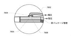
陰圧の蓄積を防止するように構成されたドレナージアセンブリの一実施形態は、一般に、体腔内に挿入するように構成された第1の端部を有する細長いカテーテルを備えてもよい。カテーテルは、それを通して画定されるカテーテル管腔と流体連通する第1の端部の又は第1の端部の近くに少なくとも一つの開口部、カテーテルの第2の端部と流体連通するドレナージ管腔、ドレナージ管腔と流体連通するリザーバ、及びドレナージ管腔及び陽圧管腔と流体連通する通気機構を有してもよい。通気機構内に弁を配置し、ドレナージ管腔内の第1の圧力レベルが第2の圧力レベルに下がるまで閉位置を維持し、弁が開位置に移動するように構成することができる。また、弁と流体連通するように通気孔を配置することができ、通気機構は、ドレナージ管腔内の液体からの通気孔の濡れを阻止するように構成され、リザーバと連通するコントローラは、リザーバ内に収集された流体量を決定するように構成されている。 One embodiment of the drainage assembly configured to prevent the buildup of negative pressure may generally include an elongated catheter with a first end configured to be inserted into the body cavity. The catheter has at least one opening at or near the first end of the first end that fluidly communicates with the catheter lumen defined through it, and the drainage lumen that fluidly communicates with the second end of the catheter. , A reservoir for fluid communication with the drainage lumen, and a ventilation mechanism for fluid communication with the drainage and positive pressure lumens. A valve can be placed within the ventilation mechanism and maintained in the closed position until the first pressure level in the drainage lumen drops to the second pressure level, and the valve can be configured to move to the open position. Vents can also be arranged to communicate fluid with the valve, the ventilation mechanism is configured to prevent the vents from getting wet from the liquid in the drainage lumen, and the controller communicating with the reservoir is the reservoir. It is configured to determine the amount of fluid collected within.
別の実施形態では、ドレナージアセンブリは、体腔内に挿入するように構成された第1の端部を有する細長いカテーテルを一般に含む陰圧の蓄積を防ぐように構成されてもよく、カテーテルはそれを通して規定されるカテーテル内腔と流体連通する端部又はその近くに少なくとも一つの開口部を有する。ドレナージ管腔は、カテーテルの第2の端部と流体連通し、ドレナージ管腔と流体連通した陽圧管腔、ドレナージ管腔と流体連通したリザーバ、及びドレナージ管腔に連結された通気機構であり、通気機構は、ドレナージ管腔内の流体からの通気孔の濡れを抑制するように構成されている。コントローラは、リザーバと通信していてもよく、コントローラは、リザーバ内に収集された流体量を決定するように構成されていてもよく、閉位置と開位置との間で構成可能な弁も含まれ、弁は弁に加えられた第1の圧力レベルがリザーバ内の第2の圧力レベルまで低下すると、閉位置から開位置へ移動する。 In another embodiment, the drainage assembly may be configured to prevent the buildup of negative pressure, generally including an elongated catheter with a first end configured to be inserted into the body cavity, through which the catheter. It has at least one opening at or near the end of fluid communication with the defined catheter lumen. The drainage lumen is a ventilation mechanism connected to a fluid communication with the second end of the catheter, a positive pressure lumen with fluid communication with the drainage lumen, a reservoir with fluid communication with the drainage lumen, and a drainage lumen. The ventilation mechanism is configured to prevent the ventilation holes from getting wet from the fluid in the drainage lumen. The controller may communicate with the reservoir, the controller may be configured to determine the amount of fluid collected in the reservoir, and may also include a configurable valve between the closed and open positions. The valve moves from the closed position to the open position when the first pressure level applied to the valve drops to the second pressure level in the reservoir.
開示された技術により測定及び/又は決定され得る特定の患者パラメータは、医療装置による患者の治療により影響を受け、及び/又は影響を与える。例えば、患者の尿量、呼吸数、心拍数、1回拍出量、1回拍出量の変動、腹腔内圧(IAP)、組織酸素化、組織ガス量、体温、血液量、及びその他の患者パラメータが及び/又は衝撃、医療により影響を受ける場合がある。医療機器によって制御される医療のいくつかの例には、呼吸器によって制御される呼吸速度と内容、IV点滴コントローラによって制御されるIV速度と内容、薬物送達装置又はIVコントローラによって制御される薬物送達、排尿ポンプ、ドレナージポンプによって制御される腹水量、及び他の医療機器によって制御される他の治療が含まれる。 Certain patient parameters that can be measured and / or determined by the disclosed techniques are affected and / or affected by the treatment of the patient with medical devices. For example, patient urine volume, respiratory rate, heart rate, one-time pumping volume, one-time pumping volume fluctuation, intraperitoneal pressure (IAP), tissue oxygenation, tissue gas volume, body temperature, blood volume, and other patients. Parameters may be affected by and / or impact, medical care. Some examples of medical devices controlled by medical devices include respiratory rate and content controlled by the respiratory system, IV rate and content controlled by the IV drip controller, and drug delivery controlled by the drug delivery device or IV controller. Includes urine pumps, ascites volume controlled by drainage pumps, and other treatments controlled by other medical devices.
体液を分析するためのシステムの一実施形態は、一般に、カテーテルの遠位端又はその近くに位置する拡張可能なバルーンを有し、バルーンに近接する1つ又は複数の開口をさらに規定する細長いカテーテル、カテーテルの近位端、陰圧が通気機構に加えられたときに空気が通過するように構成された通気機構、通気機構に連結されて1つ以上の開口部と流体連通する第1の管腔、流体連通する第2の管腔バルーン、第1の管腔の近位端に連結され、1つ又は複数の開口部と流体連通するリザーバ、及びリザーバに接続するように構成され、第1の管腔内の圧力を制御するようにプログラムされるコントローラはさらに、患者からリザーバ内で受け取った尿出力をモニタリングし、腹部内圧を決定するようにプログラムされている患者は、バルーン内の圧力の変化に部分的に基づいており、コントローラは、患者データを保存するようにさらに構成されている。 One embodiment of a system for analyzing body fluids is generally an elongated catheter that has an expandable balloon located at or near the distal end of the catheter and further defines one or more openings in the vicinity of the balloon. , The proximal end of the catheter, a ventilation mechanism configured to allow air to pass when negative pressure is applied to the ventilation mechanism, a first tube connected to the ventilation mechanism for fluid communication with one or more openings. A cavity, a second luminal balloon with fluid communication, a reservoir connected to the proximal end of the first cavity and fluid communication with one or more openings, and a first configured to connect to the reservoir. The controller, which is programmed to control the intraluminal pressure, also monitors the urine output received from the patient in the reservoir, and the patient, which is programmed to determine the abdominal pressure, is the pressure in the balloon. Partially based on changes, the controller is further configured to store patient data.
患者からの1つ以上の身体パラメータを分析するための1つの例示的な方法において、方法は一般に、少なくとも部分的に満たされた身体管腔内のカテーテルの遠位端の近く又は遠位に位置する拡張可能なバルーンを有する細長いカテーテルを配置すること、バルーンに近接してカテーテルに沿って定義された1つ以上の開口部から尿を受け取り、さらに体腔の外部にあるリザーバ内で体液を受け取り、1つ以上の開口部と流体連通している体液流体管腔、陰圧が流体管腔に加えられたときに流体管腔と連通している通気機構を介して空気を排出し、陰圧を制御するようにプログラムされたコントローラを介してリザーバ内に収容された尿の量を分析する通気機構、バルーン内の圧力の変化に部分的に基づいて患者の腹腔内圧を決定すること、コントローラを介して患者データの1つ以上のパラメータを保存することを含み得る。 In one exemplary method for analyzing one or more body parameters from a patient, the method is generally located near or distal to the distal end of the catheter within at least a partially filled body lumen. Placing an elongated catheter with an inflatable balloon, receiving urine from one or more openings defined along the catheter in close proximity to the balloon, and receiving fluid in a reservoir outside the body cavity, A fluid fluid cavity that communicates fluidly with one or more openings, and when negative pressure is applied to the fluid cavity, air is expelled through a ventilation mechanism that communicates with the fluid lumen to release negative pressure. A ventilation mechanism that analyzes the amount of urine contained in the reservoir via a controller programmed to control, determining the patient's intraperitoneal pressure based in part on changes in pressure within the balloon, via the controller It may include storing one or more parameters of patient data.
センシングフォーリーカテーテルシステムのいくつかの実施形態は、患者パラメータに関する1つ以上のデータを受け取り、この情報を使用して1つ以上の医療治療装置を制御するループコントローラを含む。ループコントローラは、患者パラメータを測定する装置、医療装置、又はその両方と統合することができる。 Some embodiments of the Sensing Foley Catheter system include a loop controller that receives one or more data about patient parameters and uses this information to control one or more medical treatment devices. The loop controller can be integrated with a device that measures patient parameters, a medical device, or both.
カテーテル上の圧力測定バルーン、例えばSensing Foley Catheterという名称の国際特許出願番号PCT/US14/44565に開示されているもの(参照によりその全体が本明細書に組み込まれる)は、患者のパラメータを測定する装置の例である。追加の実施形態が本明細書に開示される。センシングフォーリーカテーテルシステムには、圧力測定バルーン及び/又はその他のセンサ、及び尿排出量と内容を測定して、尿排出量、IAP、呼吸数、心拍数、1回拍出量組織の酸素化、尿組成、体温、その他の患者パラメータなどの患者パラメータを決定する機能が含まれる。 Pressure-measuring balloons on catheters, such as those disclosed in International Patent Application No. PCT / US14 / 44565, named Sensing Foley Cather, which are incorporated herein by reference in their entirety, measure patient parameters. This is an example of a device. Additional embodiments are disclosed herein. The sensing Foley catheter system includes a pressure measuring balloon and / or other sensor, and urine output, IAP, respiratory rate, heart rate, and one-time pumping tissue oxygenation, which measures urine output and content. Includes the ability to determine patient parameters such as urine composition, body temperature, and other patient parameters.
センシングフォーリー型カテーテルを介して測定及び/又は決定され得る他のパラメータには、尿比重及び脈圧変動性が含まれる。これらのパラメータは、人工呼吸器及び/又は注入及び/又は水分補給装置などの医療治療装置の制御を支援するために使用されてもよい。 Other parameters that can be measured and / or determined via a sensing foley catheter include urine specific gravity and pulse pressure volatility. These parameters may be used to assist in the control of medical treatment devices such as ventilators and / or infusions and / or hydration devices.
尿比重は、尿中の溶質粒子の数と重量の尺度である。通常の範囲は約1.010~1.030である。これよりも高い測定値は、脱水又は他の状態を示している可能性がある。これより低い測定値は、液体の過負荷又はその他の状態を示している可能性がある。測定は、センシングフォーリーカテーテルのセンサで行うことができる。測定結果は、患者への注入速度の増加(脱水の場合)又は減少(体液過剰の場合)を示す場合がある。測定結果は、換気パラメータや薬物注入などの変化を示す場合もある。 Urine specific gravity is a measure of the number and weight of solute particles in urine. The usual range is about 1.010 to 1.030. Measurements higher than this may indicate dehydration or other conditions. Lower readings may indicate a liquid overload or other condition. The measurement can be performed with a sensor of a sensing Foley catheter. The measurement results may indicate an increase (in the case of dehydration) or a decrease (in the case of excess fluid) infusion rate into the patient. Measurement results may indicate changes in ventilation parameters, drug infusions, etc.
脈圧変動は、人工呼吸器及び/又は流体注入装置などの医療装置に対する流体応答性の予測因子となり得る。センシングフォーリーカテーテルは圧力波形を記録でき、コントローラは呼吸サイクルと一致する最大及び最小圧力パルスを識別できる。コントローラは脈圧変動を計算できる。脈圧変動は、特定の患者が輸液療法に反応するかどうかを判断するのに役立つ。コントローラは、脈圧変動を使用してフィードバックループの治療を制御することもできる。脈圧の変動が大きい場合、患者により多くの液体が必要になることがある。脈圧の変動性が低い場合、必要な液体は少なくなる。 Pulse pressure fluctuations can be predictors of fluid responsiveness to medical devices such as ventilators and / or fluid infusion devices. Sensing Foley catheters can record pressure waveforms and the controller can identify maximum and minimum pressure pulses that match the respiratory cycle. The controller can calculate pulse pressure fluctuations. Pulse pressure fluctuations help determine whether a particular patient responds to fluid therapy. The controller can also use pulse pressure fluctuations to control the treatment of feedback loops. Patients may need more fluid if their pulse pressure fluctuates significantly. If the pulse pressure is less volatile, less fluid is needed.
センシングフォーリーカテーテルシステムは、膀胱内の圧力検知を介して心臓活動を測定することができる。センシングフォーリーカテーテルは呼吸活動と心臓活動を測定することができ、患者の呼吸数と心拍数の頻度は互いに類似している可能性があるため、患者の呼吸測定は心臓測定を歪める可能性がある。この問題を克服するために、コントローラのいくつかの実施形態は、1つ以上の吸気ポイントの終わりで人工呼吸器を一時停止し、かつ/又は1つ以上の呼気ポイントの終わりで人工呼吸器を一時停止し(毎回、例えば数秒間だけ1~3秒、又は、例えば1~4秒)、これにより、呼吸の歪みなしに心臓波形を捕捉できる。この方法で詳細な心臓波形を捕捉することで、コントローラは、敗血症の検出及び体液過剰の予防に役立つ一回拍出量変動(SVV)を決定できる。代替実施形態として、患者は、吸気点及び/又は呼気点で呼吸を止めるように求められてもよい。 The Sensing Foley Catheter System can measure cardiac activity via pressure sensing in the bladder. Patient respiratory measurements can distort cardiac measurements because Sensing Foley catheters can measure respiratory and cardiac activity, and the patient's respiratory rate and heart rate frequency may be similar to each other. .. To overcome this problem, some embodiments of the controller suspend the ventilator at the end of one or more inspiratory points and / or the ventilator at the end of one or more exhalation points. Pause (each time, eg, 1-3 seconds for a few seconds, or, eg, 1-4 seconds), which allows the heart waveform to be captured without respiratory distortion. By capturing detailed cardiac waveforms in this way, the controller can determine stroke volume fluctuations (SVVs) that help detect sepsis and prevent fluid excess. As an alternative embodiment, the patient may be asked to stop breathing at the inspiratory and / or expiratory points.
別の実施形態では、カテーテルシステムは、一般に、カテーテルの遠位端付近又は遠位端に少なくとも1つの開口部を有するカテーテル、カテーテルの近位端と流体連通するバーブ、少なくとも1つの開口部と流体連通するドレナージチューブ、及びバーブと流体連通する通気管を備えてもよい。一方向弁は、通気管と一列に並んで、バーブの近位の位置に配置されてもよく、コントローラは一方向弁と通信していてもよく、コントローラはドレナージに陰圧を加えるようにプログラムされており、その結果、一方向弁が開き、流体が通気管を通過する。 In another embodiment, the catheter system generally comprises a catheter having at least one opening near or at the distal end of the catheter, a barb that fluidly communicates with the proximal end of the catheter, at least one opening and fluid. A drainage tube for communication and a ventilation tube for fluid communication with the barb may be provided. The one-way valve may be located in line with the vent pipe and proximal to the barb, the controller may be communicating with the one-way valve, and the controller may be programmed to apply negative pressure to the drainage. As a result, the one-way valve opens and the fluid passes through the vent pipe.
別の実施形態では、流体を排出するための1つの方法は、一般に、カテーテルの遠位端の近く又は遠位に少なくとも1つの開口部を有するカテーテルを有するカテーテルの近位端と流体連通するバーブ(barb)、及び少なくとも1つの開口部と流体連通するドレナージチューブを有するカテーテルシステムを対象の身体の近くに配置することを含み得る。一方向弁と連通しているコントローラは、一方向弁が通気管と一列に配置され、バーブと流体連通している場合に作動させることができ、一方向弁はさらにバーブに近位の位置に配置される。ドレナージチューブに陰圧をかけると、一方向弁が開き、流体が通気管を通過する。 In another embodiment, one method for draining fluid is generally a barb that communicates fluidly with the proximal end of the catheter having a catheter having at least one opening near or distal to the distal end of the catheter. (Barb), and may include placing a catheter system with a drainage tube with fluid communication with at least one opening close to the subject's body. A controller that communicates with a one-way valve can be activated when the one-way valve is in line with the vent pipe and has fluid communication with the barb, with the one-way valve further proximal to the barb. Be placed. When negative pressure is applied to the drainage tube, the one-way valve opens and the fluid passes through the vent tube.
本発明の新規な特徴が記載される。本発明の特徴及び利点のより良い理解は、本発明の原理が利用される例示的な実施形態を記載する以下の詳細な説明、及び添付の図面を参照することにより得られるであろう。 Novel features of the invention are described. A better understanding of the features and advantages of the invention will be obtained by reference to the following detailed description, which describes exemplary embodiments in which the principles of the invention are utilized, and the accompanying drawings.
本発明の好ましい実施形態を本明細書で詳細に説明する。しかしながら、装置の様々な特徴の代替実施形態も可能である。これらの実施形態の例を以下に提供するが、本発明の範囲はこれらの特定の構成に限定されない。 Preferred embodiments of the present invention are described in detail herein. However, alternative embodiments of various features of the device are also possible. Examples of these embodiments are provided below, but the scope of the invention is not limited to these particular configurations.
センシングフォーリーカテーテル Sensing foley catheter
図1は、センシングフォーリーカテーテルの実施形態及びその特徴のいくつかを示す。カテーテルは、カテーテルが人間の被験者に挿入されたときの配置に応じて、被験者の外部に残る近位部分、中央部又は尿道に残る部分、及び遠位又は尿膀胱に残る部分など、さまざまな区画を持っていると理解できる。 FIG. 1 shows an embodiment of a sensing foley catheter and some of its features. The catheter can be divided into various compartments, such as the proximal part remaining outside the subject, the central part or the part remaining in the urethra, and the distal part or the part remaining in the urinary bladder, depending on the placement when the catheter is inserted into the human subject. Can be understood to have.
膀胱保持バルーン104及び保持バルーンポート118と連通する空気又は流体管腔など、様々な内部管腔がカテーテルの長さを横断する。尿ドレナージ管腔は、内部に存在する遠位開口部又は開口部106を有し、カテーテルの膀胱部分、及びカテーテルの近位端114に開口部を有する。尿ドレナージ管腔は、尿を収集容器に運ぶ尿ドレナージチューブに接続されてもよい。尿ドレナージチューブは、センシングフォーリーカテーテルとは別のものでも、一体型でもよい。いくつかの実施形態では、膀胱のドレナージ管腔及び遠位開口部は、薬剤を注入することができる、又は加熱又は冷却流体を注入することができる注入導管としても機能し得る。検体センサ(図示せず)又は温度センサ(図示せず)は、カテーテルの尿道部分又はカテーテルの膀胱内在部分のいずれかに配置することができる。電気又は光ファイバの導線は、遠位に配置されたセンサとカテーテルの近位部分との間の検知信号の通信を可能にする管腔に配置され、その後、データ処理装置又はコントローラとさらに通信する。
Various internal lumens traverse the length of the catheter, such as air or fluid lumens communicating with the
膨張可能な圧力感知バルーン108(又は開口部を横切って配置された圧力感知膜)は、カテーテルの遠位端又はその近くに配置されてもよい。圧力感知バルーン又は圧力感知膜の実施形態は、膀胱内からの圧力にさらされる遠位に面する表面と、近位流体柱に曝される近位に面する表面とを有する圧力インターフェースを備えると理解され得る。圧力感知バルーン又は膜は、カテーテルの近位端又はその近くで圧力ポート116と流体連通している流体柱又は管腔と流体連通している。(液体又は気体のいずれかの流体で満たされた)流体カラムの実施形態は、専用の管腔又は共有管腔を備えてもよい。
The inflatable pressure-sensitive balloon 108 (or pressure-sensitive membrane placed across the opening) may be placed at or near the distal end of the catheter. An embodiment of a pressure sensing balloon or pressure sensing membrane comprises a pressure interface having a distally facing surface exposed to pressure from within the bladder and a proximally facing surface exposed to a proximal fluid column. Can be understood. The pressure sensing balloon or membrane communicates with a fluid column or lumen that communicates with the
いくつかの実施形態では、温度センサは、カテーテルの遠位端又はその近くに存在してもよい。温度ポート110は、温度センサをディスプレイ、コネクタ及び/又はコントローラに接続する温度通信線112を含むことができる。
In some embodiments, the temperature sensor may be present at or near the distal end of the catheter. The
図1は複数の別個のポートを含むカテーテルの近位端を示しているが、ポートのいくつか又はすべては単一のポートに統合されるか、又は尿排出システム及び/又はコントローラに移動する尿排出ラインに統合され得る。他の管腔及び/又はポートも存在し得る。 Figure 1 shows the proximal end of a catheter containing multiple separate ports, but some or all of the ports are integrated into a single port or urine that moves to a urine drainage system and / or controller. Can be integrated into the emission line. Other lumens and / or ports may also be present.
センシングフォーリーカテーテルシステムが感知し得る、及び/又は感知されたパラメータに基づいてコントローラを介して決定し得る圧力ベースの生理学的パラメータは、例として、腹圧、呼吸数、及び心拍数、相対的な肺一回換気量プロファイル、心拍出量、相対心拍出量、絶対心拍出量を含み得る。フォーリー型カテーテルのいくつかの実施形態は、温度センサ、1つ又は複数の検体センサ、電極、並びに光源とセンサのペアのいずれかをさらに備えていてもよい。このようにさらに装備された実施形態は、例えば、血圧、酸素飽和度、パルスオキシメトリー、EKG、及び毛細血管充填圧などの他の形態の生理学的データを送達することができる。 Pressure-based physiological parameters that can be sensed by the Sensing Foley catheter system and / or determined via the controller based on the sensed parameters are, for example, abdominal pressure, respiratory rate, and cardiac output, relative. It may include lung tidal volume profile, cardiac output, relative cardiac output, absolute cardiac output. Some embodiments of the Foley catheter may further comprise a temperature sensor, one or more specimen sensors, electrodes, and any of a light source / sensor pair. Such further equipped embodiments can deliver other forms of physiological data such as blood pressure, oxygen saturation, pulse oximetry, EKG, and capillary filling pressure.
センシングフォーリーカテーテルの実施形態は、以下の例に含まれるような、臨床的に関連する複数のパラメータのうちの任意の1つ以上を感知することができ得る:尿pH、尿酸素含有量、尿硝酸含有量、呼吸数、心拍数、膀胱壁又は尿道壁の灌流圧、膀胱又は尿道内の温度、膀胱壁又は尿道上のセンサを介した心電図、呼吸量、呼吸圧、腹膜圧、尿グルコース、尿道粘膜を介した血糖及び/又は膀胱粘膜、尿タンパク質、尿ヘモグロビン、血圧。 Embodiments of sensing foley catheters may be able to sense any one or more of a plurality of clinically relevant parameters, such as those included in the following examples: urine pH, urine oxygen content, urine. Nitrate content, respiratory rate, heart rate, perfusion pressure on bladder wall or urinary tract wall, temperature in bladder or urinary tract, electrocardiogram via sensor on bladder wall or urinary tract, respiratory volume, respiratory pressure, peritoneal pressure, urinary glucose, Blood glucose and / or bladder mucosa via the urinary mucosa, urinary protein, urinary hemoglobin, blood pressure.
いくつかの実施形態では、カテーテルは複数のパラメータを感知することができるが、いくつかの実施形態は、集中用途(例えば、呼吸困難の患者の呼吸数)のための単一のパラメータに制限される場合がある。 In some embodiments, the catheter can sense multiple parameters, but some embodiments are limited to a single parameter for intensive use (eg, respiratory rate in patients with dyspnea). May occur.
開示された技術は、膀胱内からの腹圧の高解像度の経時的プロファイル(時間の関数としての圧力)を捕捉し、腹膜圧、呼吸数、及び心拍数を含む特定の生理学的ソースに割り当て可能な別個の圧力プロファイルに変換及び処理できる。技術によって提供されるように、十分に速いサンプリング速度で圧力プロファイルを追跡することにより、圧力プロファイルは、相対的肺一回換気量、心拍出量、相対心拍出量、及び絶対心拍出量にさらに分解及び/又は分析できる。 The disclosed technique captures a high resolution temporal profile of abdominal pressure from within the bladder (pressure as a function of time) and can be assigned to specific physiological sources including peritoneal pressure, respiratory rate, and heart rate. Can be converted and processed into separate pressure profiles. By tracking the pressure profile at a sufficiently fast sampling rate, as provided by the technique, the pressure profile can be used for relative lung tidal volume, cardiac output, relative cardiac output, and absolute cardiac output. Can be further decomposed and / or analyzed into quantities.
したがって、開示される技術の態様は、膀胱内の圧力の変化に応じて産生される圧力信号の忠実度及び分解能に関し、そのような変化は、腹膜腔内の圧力プロファイルを反映し、そのような圧力プロファイルは、前述の生理学的ソースからの蓄積的入力を含む。この技術の側面はさらに、圧力信号の高度に分解可能な電気信号への変換の忠実度と解像度に関連している。技術の側面は、さらに、腹膜腔内の圧力プロファイルの代理である電気信号プロファイルの全体を、生理学的ソースに割り当てることができるコンポーネントプロファイルに処理することに関する。 Accordingly, aspects of the disclosed technique relate to the fidelity and resolution of the pressure signal produced in response to changes in pressure within the bladder, such changes reflecting the pressure profile within the peritoneal cavity and such. The pressure profile includes accumulative inputs from the aforementioned physiological sources. Aspects of this technique are further related to the fidelity and resolution of the conversion of pressure signals into highly decomposable electrical signals. An aspect of the technique further relates to processing the entire electrical signal profile, which is a surrogate for the pressure profile in the peritoneal cavity, into a component profile that can be assigned to a physiological source.
圧力センサとしての膨張したバルーンの感度は、一部には、ベースライン条件としてのバルーン膜の前後の圧力差の関数である。バルーンは、ベースラインの圧力差がゼロに近いときに、圧力に対して最大の感度を持つ。ベースライン圧力差が大きくなると、感圧バルーンの感度が低下する。したがって、開示された技術は、バルーンを膨張状態に維持するが、最小の圧力差で自動プライミング方法を提供する。 The sensitivity of the inflated balloon as a pressure sensor is, in part, a function of the pressure difference before and after the balloon membrane as a baseline condition. The balloon has maximum sensitivity to pressure when the baseline pressure difference is close to zero. As the baseline pressure difference increases, the sensitivity of the pressure sensitive balloon decreases. Accordingly, the disclosed technique provides an automated priming method with minimal pressure difference while keeping the balloon inflated.
生理学的圧力プロファイルを効果的に捕捉するために、プロファイルの変化の固有の頻度を解決するのに十分な速度でプロファイルをサンプリングする必要がある。この考慮事項は、ナイキスト-シャノンサンプリング定理によって通知される。この定理では、Bサイクル/秒の頻度で実行される事象を解決するには、少なくとも2Bサンプル/秒のサンプリング頻度が必要であると述べている。例えば、生理的圧力サイクルに適用される場合、70拍/分の心拍数は、サイクルを効果的に捕捉するために少なくとも140サンプル/分のサンプリングレートを必要とする。この関係は、相対的な肺一回換気量、心拍出量、相対的な心拍出量、絶対心拍出量などの生理学的圧力サイクルを捕捉するために特に必要なサンプリングレートを指定する開示技術の側面の基礎となる。 In order to effectively capture the physiological pressure profile, the profile needs to be sampled fast enough to resolve the inherent frequency of profile changes. This consideration is communicated by the Nyquist-Shannon sampling theorem. This theorem states that a sampling frequency of at least 2B samples / second is required to solve an event that is performed at a frequency of B cycles / second. For example, when applied to a physiological pressure cycle, a heart rate of 70 beats / minute requires a sampling rate of at least 140 samples / minute to effectively capture the cycle. This relationship specifies the sampling rate specifically required to capture physiological pressure cycles such as relative lung tidal volume, cardiac output, relative cardiac output, and absolute cardiac output. It forms the basis of aspects of the disclosed technology.
本技術の実施形態は、順応性膜又は非順応性膜のいずれかを有するバルーンによって表され得るような圧力インターフェースを含む。 Embodiments of the invention include a pressure interface as can be represented by a balloon having either an adaptable or non-adaptable membrane.
本技術の実施形態による、拡張可能な圧力感知バルーンは、順応性又は非順応性の少なくとも2つの基本形態のうちの1つ又は複数を想定してもよい。一般に従来のパーティバルーンに例えることができる順応性バルーンタイプでは、感圧バルーンは順応性膜から形成されるか、順応性膜を含む。したがって、膜の表面積は、バルーンの膨張の関数として膨張又は収縮する。膜の順応性は、膨張の異なるレベルで、全体としてバルーンのさまざまな機能を決定する。拡張時に、バルーンは、拘束されていない場合、バルーンが形成されるマンドレルによって決定されるように、実質的に一定又は好ましい形状又は形状を維持する。バルーンが最小容積から最大容積まで膨張すると、バルーンの膜は緊張状態を維持する。順応性膜の順応性の範囲内で、膨張中の圧力の増加により、結果として体積が拡大する。バルーンは、全体として、形状が拡張又は膨張時に遭遇する可能性のある空間的制約に対応するという点で部分的に適合していると見なされる場合があるが、バルーンは優先又はネイティブの形状を持ち、そのような形状の優先度は、形状順応性又は非順応性バルーンによって示されるような適合性のレベルを防ぐ。 The expandable pressure-sensitive balloon according to an embodiment of the art may be assumed to be one or more of at least two basic embodiments of adaptable or non-adaptable. In the adaptable balloon type, which can generally be compared to a conventional party balloon, the pressure sensitive balloon is formed from or contains an adaptable membrane. Therefore, the surface area of the membrane expands or contracts as a function of balloon expansion. Membrane adaptability determines the various functions of the balloon as a whole at different levels of swelling. Upon expansion, the balloon, if not constrained, maintains a substantially constant or preferred shape or shape, as determined by the mandrel in which the balloon is formed. When the balloon inflates from a minimum volume to a maximum volume, the balloon membrane remains tense. Within the adaptability of the adaptable membrane, the increase in pressure during expansion results in an increase in volume. Balloons may be considered as a whole to be partially adapted in that their shape accommodates spatial constraints that may be encountered during expansion or expansion, but balloons have a preferred or native shape. Having such a shape priority prevents the level of suitability as indicated by the shape adaptable or non-adaptive balloon.
非順応性バルーンでは、拡張可能な圧力感知バルーンは、非弾性膜、又は実質的に非弾性の膜から形成されるか、又はそれらを含む。したがって、膜の表面積は、バルーンの膨張/加圧のレベルに応じて膨張又は収縮しない。非順応性の圧力感知バルーンは、一般的に従来のMylar(登録商標)バルーンに例えられる。膜の順応性の欠如は、全体として、膨張の異なるレベルでのバルーンのさまざまな特徴を決定する。バルーンが最小容積から最大容積に近いレベルまで拡張すると、バルーンの膜はしなやかで、ある程度のたるみがある。不適合なバルーンの膨張は、膜のしわやひだを外側に向けて滑らかにすることで起こる。非順応性バルーンの収縮又は圧縮は、一般的に内側に向かうしわ及び折り畳みによって発生する。順応性のないバルーンが閉じ込め空間に入らずに完全に膨張する(又は実質的に膨張する)場合、バルーンの膜又は布の形状によって決定される好ましい形状又は自然な形状を想定する。しかし、部分的に膨張した状態では、バルーンは全体として非常に柔軟で順応性があり、閉じ込め空間によって指示される形状を広く取る。 In non-adaptive balloons, the expandable pressure-sensitive balloon is formed from, or contains, an inelastic membrane, or a substantially inelastic membrane. Therefore, the surface area of the membrane does not expand or contract depending on the level of expansion / pressurization of the balloon. The non-adaptive pressure sensing balloon is generally likened to a conventional Mylar® balloon. The lack of membrane adaptability, as a whole, determines the various characteristics of the balloon at different levels of swelling. When the balloon expands from a minimum volume to a level close to the maximum volume, the balloon membrane is supple and has some sagging. Incompatible balloon swelling occurs by smoothing the wrinkles and folds of the membrane outwards. The contraction or compression of the non-adaptive balloon is generally caused by inward wrinkles and folds. If the inflexible balloon does not enter the confinement space and is fully inflated (or substantially inflated), assume a preferred or natural shape as determined by the shape of the balloon's membrane or cloth. However, in the partially inflated state, the balloon as a whole is very flexible and adaptable, taking a wide range of shapes dictated by the confinement space.
技術の実施形態による拡張可能な圧力感知バルーンはまた、順応性及び非順応性の2つの基本的な形態の両方の特徴を含み得る。これらの実施形態では、膜は、順応性のある領域と非順応性の領域を含むことができる。このハイブリッドタイプのバルーンは、全体として、上記のように、順応性バルーンと非順応性バルーンの両方の動作面から描画する方法で動作する。さらに、順応性バルーンは、均一な組成又は厚さではない膜で形成されてもよい。そのような実施形態では、異なる厚さ又は組成の領域は、さまざまな程度の順応性を有することができ、したがって、バルーンの拡張中のこれらの領域の挙動に影響を及ぼす。さらに他の実施形態では、膜の順応性は、1つ以上の方向の順応性を可能にする傾向があるバイアス又は極性を有し、1つ以上の他の方向の順応性を禁止する傾向がある。 The expandable pressure-sensitive balloon according to an embodiment of the technique may also include features of both the two basic forms of adaptability and non-adaptability. In these embodiments, the membrane can include adaptive and non-adaptive regions. As a whole, this hybrid type balloon operates by drawing from the operating surface of both the adaptive balloon and the non-adaptable balloon as described above. In addition, the adaptable balloon may be formed of a membrane that is not of uniform composition or thickness. In such embodiments, regions of different thickness or composition can have varying degrees of adaptability and thus affect the behavior of these regions during balloon expansion. In yet other embodiments, the adaptability of the membrane has a bias or polarity that tends to allow adaptability in one or more directions and tends to prohibit adaptability in one or more other directions. be.
技術の実施形態による拡張可能な圧力感知バルーンはまた、順応性及び非順応性の2つの基本的な形態の両方の特徴を含み得る。これらの実施形態では、膜は、順応性のある領域と非順応性の領域を含むことができる。このハイブリッドタイプのバルーンは、全体として、上記のように、順応性バルーンと非順応性バルーンの両方の動作面から描画する方法で動作する。さらに、順応性バルーンは、均一な組成又は厚さではない膜で形成されてもよい。そのような実施形態では、異なる厚さ又は組成の領域は、さまざまな程度の順応性を有することができ、したがって、バルーンの拡張中のこれらの領域の挙動に影響を及ぼす。さらに他の実施形態では、膜の順応性は、1つ以上の方向の順応性を可能にする傾向があるバイアス又は極性を有し、1つ以上の他の方向の順応性を禁止する傾向がある。 The expandable pressure-sensitive balloon according to an embodiment of the technique may also include features of both the two basic forms of adaptability and non-adaptability. In these embodiments, the membrane can include adaptive and non-adaptive regions. As a whole, this hybrid type balloon operates by drawing from the operating surface of both the adaptive balloon and the non-adaptable balloon as described above. In addition, the adaptable balloon may be formed of a membrane that is not of uniform composition or thickness. In such embodiments, regions of different thickness or composition can have varying degrees of adaptability and thus affect the behavior of these regions during balloon expansion. In yet other embodiments, the adaptability of the membrane has a bias or polarity that tends to allow adaptability in one or more directions and tends to prohibit adaptability in one or more other directions. be.
これらのデータは、小さな直径の小児用カテーテルにおける圧力変換システムの実施形態を4Fという小さなサイズまで使用することの適切性を示している。この実施形態においても、カテーテルの先端は、圧力感知バルーンを追加しても一貫して小さな直径を可能にするために、カテーテルの残りの部分よりも低いプロファイルであり得る。したがって、本発明のカテーテルは、より適切で侵襲性の低いモニタリング方法が切実に必要とされる小児の適応症に独特に適している。別の実施形態では、必要な管腔の数を最小限にするために、保持バルーン自体を圧力バルーンとして使用することができる。一実施形態では、保持バルーンは、完全に膨張した状態で使用され、IAPのマクロトレンドを追跡するためにのみ使用される。別の実施形態では、保持バルーンは、圧力の小さな変化に対するバルーンの感度を高めるためにわずかに膨らまされる。この実施形態は、心拍数、相対的な一回拍出量、相対的な心拍出量、呼吸数、及び相対的な一回換気量などのミクロパラメータのより細かい測定を可能にする。また、圧力管腔を小さくすると、センサなどの他のテクノロジー用の大きなカテーテルにスペースを確保できる。 These data demonstrate the suitability of using embodiments of the pressure conversion system in small diameter pediatric catheters up to a small size of 4F. Also in this embodiment, the tip of the catheter can have a lower profile than the rest of the catheter to allow consistently smaller diameters with the addition of a pressure sensitive balloon. Therefore, the catheters of the present invention are uniquely suitable for pediatric indications in which more appropriate and less invasive monitoring methods are urgently needed. In another embodiment, the retention balloon itself can be used as a pressure balloon to minimize the number of lumens required. In one embodiment, the retention balloon is used in a fully inflated state and is only used to track the macrotrend of the IAP. In another embodiment, the retention balloon is slightly inflated to increase the sensitivity of the balloon to small changes in pressure. This embodiment allows for finer measurements of microparameters such as heart rate, relative stroke volume, relative cardiac output, respiratory rate, and relative tidal volume. The smaller pressure lumen also provides space for larger catheters for other technologies such as sensors.
保持バルーンが圧力バルーンとして使用されるセンシングフォーリーカテーテルの実施形態では、保持バルーン内で測定される圧力は、保持バルーンとして機能するのに十分なだけバルーンを膨張させるのに必要な圧力によって相殺される。その結果、膨張圧力、及び場合によっては膀胱の内面と接触している保持バルーンから生じる圧力を圧力測定値から差し引く必要がある。このようにして、小さな圧力変化は、個別の圧力バルーンで測定されたものと同様に追跡できる。膨張圧力オフセットは、患者に最初に挿入されたときに保持バルーン内の圧力を測定するか、患者の外部で保持バルーンの膨張圧力を測定するか、又は他の手段で決定できる。保持バルーンは、流体、空気、又は他の適切なガスで満たされていてもよい。 In an embodiment of a sensing Foley catheter in which a retention balloon is used as a pressure balloon, the pressure measured within the retention balloon is offset by the pressure required to inflate the balloon enough to function as a retention balloon. .. As a result, the inflatable pressure and, in some cases, the pressure generated by the holding balloon in contact with the inner surface of the bladder must be subtracted from the pressure measurement. In this way, small pressure changes can be tracked as if they were measured with individual pressure balloons. The expansion pressure offset can be determined by measuring the pressure inside the retention balloon when first inserted into the patient, measuring the expansion pressure of the retention balloon outside the patient, or by other means. The retention balloon may be filled with fluid, air, or other suitable gas.
開示された技術の実施形態は、圧力センサが、光ファイバ、歪みゲージ、磁気、共鳴、及び/又は他の適切な技術を使用するものなどの機械的圧力センサである実施形態を含み得る。 Embodiments of the disclosed technique may include embodiments in which the pressure sensor is a mechanical pressure sensor, such as one that uses an optical fiber, strain gauge, magnetism, resonance, and / or other suitable technique.
図2は、センシングフォーリーカテーテルシステムの実施形態によって提供される、被験者からの呼吸数感知データの例を示す。このテスト期間中、被験者は次のような呼吸シーケンスを実行する。(1)呼気の終わりに呼気、(2)バルサルバ、(3)過呼吸、(4)バルサルバ、及び(5)吸気の終わりに呼気。 FIG. 2 shows an example of respiratory rate sensing data from a subject provided by an embodiment of a sensing Foley catheter system. During this test period, subjects perform the following breathing sequence. (1) Exhalation at the end of exhalation, (2) Balsalva, (3) Hyperventilation, (4) Balsalva, and (5) Exhalation at the end of inspiration.
図3は、図2に示したものと同様の呼吸プロファイルにおける通常の呼吸周期の詳細な部分を示している。圧力曲線は呼吸ピークを明確に示しているため、呼吸数と心拍数のピークを決定できる。したがって、心拍数を決定できる。 FIG. 3 shows a detailed portion of the normal respiratory cycle in a respiratory profile similar to that shown in FIG. The pressure curve clearly shows the respiratory peaks so that the respiratory and heart rate peaks can be determined. Therefore, the heart rate can be determined.
図4は、センシングフォーリーカテーテルシステムの実施形態によって提供される、被験者からの心拍数及び相対心拍出量感知データの例、並びに同時に独立して測定されるEKGトレースを示す。このグラフは、センシングフォーリーカテーテルで測定された心拍数のピークが心拍数と一致していることを明確に示している。 FIG. 4 shows an example of heart rate and relative cardiac output sensing data from a subject provided by an embodiment of a sensing Foley catheter system, as well as an EKG trace measured simultaneously and independently. This graph clearly shows that the peak heart rate measured with a sensing Foley catheter coincides with the heart rate.
図5は、心拍の増加した振幅によって実証されるように、心拍出量が増加する人間の脚上げ運動における相対的心拍出量感知に関連するデータを示す。 FIG. 5 shows data related to relative cardiac output sensing in human leg-raising exercises with increased cardiac output, as demonstrated by the increased amplitude of the heart rate.
図6及び7は、IACUCが承認したプロトコルの下でヨークシャー豚を用いて行われた研究に由来している。図6は、センシングフォーリーカテーテルシステムの実施形態によって提供される、ブタからの呼吸数に焦点を合わせた腹膜感知データの例を示している。図7は、腹腔内高血圧を検出するセンシングフォーリーカテーテルシステムの実施形態の能力を実証するブタ研究の一例を示している。この研究では、腹膜腔に5mmテナミアントロカールでアクセスした。次に、トロカールを蠕動ポンプを介して乳酸リンゲル液の5Lバッグに取り付け、1分あたり約1Lの速度で溶液を注入した。約20mmHgの圧力が得られた後、流体の流れは中断され、その後、空洞に出入りする正味の流体の流れはなくなった。 Figures 6 and 7 are derived from studies performed with Yorkshire pigs under a protocol approved by IACUC. FIG. 6 shows an example of peritoneal sensing data focused on respiratory rate from a pig provided by an embodiment of a sensing Foley catheter system. FIG. 7 shows an example of a pig study demonstrating the ability of an embodiment of a sensing Foley catheter system to detect intra-abdominal hypertension. In this study, the peritoneal cavity was accessed with a 5 mm tenamian trocar. Next, the trocar was attached to a 5 L bag of Lactated Ringer's solution via a peristaltic pump, and the solution was injected at a rate of about 1 L per minute. After a pressure of about 20 mmHg was obtained, the fluid flow was interrupted and then there was no net fluid flow in and out of the cavity.
図8は、圧力(対数目盛のmmHg)対周波数(Hz)の2次元プロットとして概略的に配列された腹腔内圧、呼吸波圧、及び心圧を示している。圧力と周波数の間には反比例の関係があり、この方法で配列された場合、さまざまな生理学的圧力関連パラメータが異なるセクターを占めることがわかりる。本明細書に開示される方法の実施形態は、生理学的起源に応じて、単一の全体の時間的圧力プロファイルを別個のサブプロファイルに分解できるのは、これらの圧力及び/又は周波数プロファイルの両方の明確さによる。腹腔内圧測定は、約0Hzから約0.5Hzの周波数範囲で解決できる。呼吸圧測定は、約0.25Hz~約0.75Hzの周波数範囲で解決できる。心圧測定は、約0.75Hzから約3.0Hzの周波数範囲で解決できる。腹腔内圧測定は、約5mmHgから約30mmHgの振幅範囲で解決できる。呼吸圧の測定値は、約0.5mmHgから約5mmHgの振幅範囲で解決できる。心圧測定は、約0mmHgから約0.5mmHgの振幅範囲で解決される場合がある。サンプリング周波数(圧力測定が行われる周波数)は、分解能周波数の約2倍であることが望ましい。例えば、サンプリング周波数は、腹腔内圧測定では約0Hz-1Hz、呼吸圧測定では0.5Hz-1.5Hz、心圧測定では1.5Hz-6Hzになる。 FIG. 8 shows intraperitoneal pressure, respiratory wave pressure, and cardiac pressure generally arranged as a two-dimensional plot of pressure (mmHg on a logarithmic scale) vs. frequency (Hz). It can be seen that there is an inverse proportional relationship between pressure and frequency, and that different physiological pressure-related parameters occupy different sectors when arranged in this way. Embodiments of the methods disclosed herein are capable of decomposing a single overall temporal pressure profile into separate subprofiles, both of these pressure and / or frequency profiles, depending on their physiological origin. Depends on the clarity of. Intraperitoneal pressure measurements can be resolved in the frequency range from about 0 Hz to about 0.5 Hz. Respiratory pressure measurements can be resolved in the frequency range of about 0.25 Hz to about 0.75 Hz. Cardiac pressure measurements can be resolved in the frequency range from about 0.75 Hz to about 3.0 Hz. Intraperitoneal pressure measurements can be resolved in an amplitude range of about 5 mmHg to about 30 mmHg. Respiratory pressure measurements can be resolved in an amplitude range of about 0.5 mmHg to about 5 mmHg. Cardiac pressure measurements may be resolved in the amplitude range of about 0 mmHg to about 0.5 mmHg. The sampling frequency (frequency at which pressure measurement is performed) is preferably about twice the resolution frequency. For example, the sampling frequency is about 0 Hz-1 Hz for intraperitoneal pressure measurement, 0.5 Hz-1.5 Hz for respiratory pressure measurement, and 1.5 Hz-6 Hz for cardiac pressure measurement.
図9は、膀胱内から検出される、腹腔内の様々な周波数及び振幅の波として動的に発生する圧力をモニタリングする方法の実施形態のフロー図を提供する。圧力インターフェースの機関を通じて、高忠実度の圧力プロファイルが産生され、流体カラムを通じて近位に送信される。より近位では、圧力トランスデューサが高忠実度圧力波を、圧力周波数と振幅の情報となる高忠実度電気信号に変換する。産生された忠実度の高い電気信号は、コントローラによって処理され、腹圧、呼吸数、心拍数、相対心拍出量、及び患者の運動又は活動などの特定の生理学的ソースに起因する全体的な圧力プロファイル内の成分を反映するデータサブセットが生成される。 FIG. 9 provides a flow chart of an embodiment of a method of monitoring pressure dynamically generated as waves of various frequencies and amplitudes in the abdominal cavity detected from within the bladder. A high fidelity pressure profile is produced through the engine of the pressure interface and transmitted proximally through the fluid column. More proximally, a pressure transducer transforms a high fidelity pressure wave into a high fidelity electrical signal that provides information on pressure frequency and amplitude. The high-fidelity electrical signals produced are processed by the controller and are global due to specific physiological sources such as abdominal pressure, respiratory rate, heart rate, relative cardiac output, and patient exercise or activity. A data subset is generated that reflects the components in the pressure profile.
センシングフォーリーカテーテルシステム Sensing foley catheter system
図10Aは、エアロック清掃機構及び流体収集及び分析システムの実施形態とともに使用されるセンシングフォーリーカテーテルの実施形態を示す。尿排出と圧力測定値の両方が、尿排出ラインのエアロックの除去又は削減の恩恵を受ける。 FIG. 10A shows an embodiment of a sensing Foley catheter used with an embodiment of an airlock cleaning mechanism and a fluid collection and analysis system. Both urine drainage and pressure measurements benefit from the removal or reduction of airlocks in the urine drainage line.
センシングフォーリーカテーテル1000は、図1に示されるセンシングフォーリーカテーテルに類似している。センシングフォーリーカテーテルは、膀胱1014で使用中に示される。図1に示されるカテーテルの近位端のいくつかのポートは、図10Aに示される実施形態。尿ドレナージチューブ1001もここに示されている。尿ドレナージチューブは、センシングフォーリーカテーテルと組み合わせるか、別のコンポーネントにすることができる。尿ドレナージチューブ1001及び/又はセンシングフォーリーカテーテルはまた、通気孔バーブ(又はバーブ)1016を含み得るか、又は通気孔バーブは別個のコンポーネントであり得る。エアロック清掃機構及び流体収集及び分析システム1002もここに示されており、センシングフォーリーカテーテル1000と流体連通している尿ドレナージチューブ1001と流体連通している。エアロック清掃機構及び流体収集及び分析システムはベース/コントローラ1018、流体収集バッグ1020及びリザーバ又はカセット1022を含む。センシングフォーリーカテーテル1000、尿ドレナージチューブ1001、及びエアロック清掃機構及び流体収集及び分析システム1002の組み合わせは、本明細書ではセンシングフォーリーカテーテルシステムとも呼ばれる。センシングフォーリーカテーテル、尿排出ライン、及びリザーバ/カセットは使い捨てで、ユニットとして販売できる。この使い捨てアセンブリは図10Dに示されており、フォーリーカテーテル1000の感知、尿ドレナージチューブ1001(通気孔バーブを含む)、及びリザーバ/カセット1022を含む。
The
通気孔バーブ1016は、1つ又は複数の通気孔1006及び尿サンプリングポート1004を含むことができる。この実施形態では、通気孔1006は、疎水性膜などの液体ではなく気体の透過を可能にする膜から作られることが好ましい。そのような例示的な通気孔の一例は、PTFE(ポリテトラフルオロエチレン)、ePTFE(拡張PTFE)、又はVersapor(登録商標)(ポール・コーポレーション、ニューヨーク州ポートワシントンから)膜であるが、他の材料を使用してもよい。通気管により、ドレナージチューブに陰圧が加えられるとシステムに空気が入り、ドレナージラインのエアロックにより陽圧が生じると空気がシステムから出ることができる。そのような機構は、例えば膀胱壁での吸引外傷を防ぐ。通気孔1006は、空気がドレナージラインから出たり、ドレナージラインに入るのを防ぐ一方向弁を組み込んでもよい。好ましい実施形態では、一方向弁を使用して、空気がドレナージラインを出るのを防ぐが、通気孔1006を介して空気がドレナージラインに入ることを可能にする。このように、弁は尿が通気孔1006と接触することも防ぐ。
The
尿ドレナージチューブ1001は、圧力管腔1010、温度管腔1008、及び尿管腔1012を含むいくつかの管腔を含み得る。圧力管腔1010は、圧力感知バルーン108並びにコントローラ1018内の圧力トランスデューサインターフェース1026と流体連通する。フォーリーカテーテルのセンサに温度センサ(図示せず)があり、コントローラに温度コネクター1024がある。尿管腔1012は、1つ又は複数の開口部106及び尿リザーバ又はカセット1022と流体連通している。
The
使い捨て測定容器、収集容器、チャンバ又はカセットコンポーネント1022は、カセットマウント、ベース又はコントローラ1018に収まり、コントローラのコンポーネントと連動するように設計されている。コントローラカセットインターフェース(カセットポンプインターフェース1148の後ろ)は、ポンプ1134及び使い捨てカセットコンポーネント上のカセットポンプインターフェース1148に接続する。ポンプは、カセットコンポーネントの内部に真空を産生するように設計されており、真空はドレナージラインの尿ドレナージ管腔に送られる。好ましくは、収集容器/カセットは、ポンプが陰圧をかけるときに一定の容積を維持するために剛性である。適用される陰圧のレベルは、圧力センサによってモニタリングできる。エアロックのクリアランス中、圧力は図59に示すような特徴的な曲線に従いる。吸引が適用されると圧力が低下し、尿のメニスカスがドレナージチューブの最低点を通過すると、最終的に変曲点に達する。この時点で、エアロックをクリアし続けるために必要な吸引量は少ないため、エアロックが完全にクリアされたら膀胱に送られる吸引量を最小限に抑えるために、ポンプの出力を下げることができる。例えば、この圧力検出機能を持たない大型の船舶は、エアロックが解除されてから大気と平衡する時間になる前に、実質的な陰圧を膀胱に伝達する。コントローラ圧力インターフェース(カセット圧力インターフェース1150の後ろ)は、圧力トランスデューサなどの圧力測定デバイスとカセット圧力インターフェース1150に接続する。圧力測定装置は、圧力トランスデューサなどの圧力測定装置にかかる圧力に基づいて、尿又は他の液体の体積を測定するように設計されている。超音波トランスデューサインターフェース1130はまた、尿量測定を提供することである。超音波測定は、圧力測定と組み合わせて使用することができる。又は、尿又は他の液体の体積出力を決定するために使用できる。アクティブピンチ弁1132は、カセットの流出チューブに接続するように設計されている。ピンチ弁はカセット容器の空を制御するためのものであり、圧力及び/又は超音波測定によって決定されるように、尿出力がカセット内の特定の体積に達すると尿/流体を放出するようにピンチ弁はコントローラによって制御される。カセット内の尿の量が測定され、尿が特定の量に達すると、尿はピンチ弁を介して尿ドレナージバッグ1020に排出される。例えば、カセット内の尿の量が約50mLに達すると、カセットは空になる。あるいは、カセット内の尿の量が約40mLに達したら、カセットを空にすることができる。あるいは、カセット内の尿の量が約30mLに達したら、カセットを空にすることができる。あるいは、カセット内の尿の量が約20mLに達したら、カセットを空にすることができる。あるいは、カセット内の尿の量が約10mLに達したときに、カセットを空にすることができる。このようにして、尿の排出量を経時的に正確に測定できる。
The disposable measuring container, collection container, chamber or
カセットを空にすることは、空にするプロセス中にカセットを加圧することにより増強又は加速され得る。 Emptying the cassette can be augmented or accelerated by pressurizing the cassette during the emptying process.
あるいは、コントローラは、カセットを空にする間の設定時間を利用し、空にする直前にカセット内の尿の量を測定してもよい。あるいは、コントローラは、ポンプの起動によってトリガーされるエアロックの取り外しなどの通気孔が発生したときにカセットを空にすることができる。例えば、コントローラは定期的なエアロッククリアランスサイクルを設定し、その後にカセット内の尿量を測定し、その後カセットを空にすることができる。 Alternatively, the controller may utilize the set time while emptying the cassette to measure the amount of urine in the cassette just before emptying. Alternatively, the controller can empty the cassette when vents occur, such as the removal of an airlock triggered by the activation of the pump. For example, the controller can set a periodic airlock clearance cycle, then measure the amount of urine in the cassette, and then empty the cassette.
例えば、コントローラは、尿量が約50mLに達したときにピンチ弁を制御してリザーバ/カセットを空にすることができる。あるいは、コントローラはピンチ弁を制御して、カセット内の尿量を測定した後、1時間ごとにリザーバ/カセットを空にすることができる。あるいは、コントローラはピンチ弁を制御して、ポンプの運転などの尿排出通気孔中又はその後にリザーバ/カセットを空にすることができる。又は、コントローラはこれらのトリガーの組み合わせを使用して、ピンチ弁を制御してリザーバ/カセットを空にすることができる。 For example, the controller can control the pinch valve to empty the reservoir / cassette when the urine volume reaches about 50 mL. Alternatively, the controller can control the pinch valve to measure the amount of urine in the cassette and then empty the reservoir / cassette every hour. Alternatively, the controller can control the pinch valve to empty the reservoir / cassette during or after the urine drain vent, such as when operating a pump. Alternatively, the controller can use a combination of these triggers to control the pinch valve to empty the reservoir / cassette.
圧力ベース、抵抗ベース、静電容量ベース、超音波ベース、又は光学ベースの技術を含む、圧力及び/又は超音波に加えて、又はその代わりに、尿量を測定するために他の技術が使用される場合がある。複数の技術を使用して、測定値を互いに比較し、体積測定の精度を向上させることができる。より正確な尿量測定を得るために、1つ又は複数の技術によって行われた複数の量測定を冗長性、バックアップ、又は互いに組み合わせて使用できる。 Other techniques used to measure urine output in addition to or instead of pressure and / or ultrasound, including pressure-based, resistance-based, capacitance-based, ultrasound-based, or optical-based techniques. May be done. Multiple techniques can be used to compare measurements to each other and improve the accuracy of volumetric measurements. Multiple quantification measurements made by one or more techniques can be used in redundancy, backup, or in combination with each other to obtain more accurate urine volume measurements.
ベッドフック1116は、必要に応じてコントローラをベッド又は他のデバイスにフックするためのものである。また、患者輸送のためにコントローラをポータブルデバイスにフックするのにも使用できる。収集バッグのフック/穴1102は、尿/流体がピンチ弁を通過した後、尿/流体が最終的に収集されるドレナージバッグを取り付けるためのものである。収集バッグフック1102は、バッグ内の流体の重量を決定できるようにひずみ測定値を提供し、したがってバッグ内の流体の体積を決定する別の方法を提供するように設計することができる。例えば、圧電トランスデューサが使用されてもよい。コントローラは、比重の決定を使用して、重量と比重に基づいて有用な体積測定値を決定することもできる。
The
画面1110は、現在の尿/体液量の状態、システムの状態などを含む情報を表示するためのものである。画面1110はタッチスクリーンでもあり、設定、画面表示の変更、メニューの変更などを含む入力を受け取ることができる。圧力ポート1026は膀胱圧力ライン1010に接続し、使用される場合、センシングフォーリーカテーテルを使用して膀胱圧力を測定する。あるいは、圧力ポートは、カセット1022の下のカセットマウント内又はコントローラ/ベースの他の場所に配置されてもよい。ポート1024の温度は、管腔1008を介したセンシングフォーリーカテーテル又は他の手段を介して体温を測定するサーミスタ/温度センサに接続する。温度出力ポート1122は、温度測定値を外部デバイス及び/又はモニタに送信するためのものである。アダプタポート1124は、RFIDアダプタの場合など、コントローラを他のデバイスに適合させるためのものである。これを使用して、IAP、呼吸数、心拍数、心拍出量、又はセンシングフォーリーカテーテルで測定できるその他のパラメータの測定など、追加/高度な機能をアクティブにすることができる。これにより、その情報が必要な場合にのみ、追加のパラメータを有効化し、病院で支払うことができる。高度な機能の起動は、例えば異なる使い捨てコンポーネントの使用によって制御することもできる。あるいは、使い捨て機能の一部として、又は個別に購入したソフトウェアアップグレードによって、高度な機能を有効にすることができる。ソフトウェアのアップグレードは、ワイヤレス、USBドングル、micro-SDカード、EPROMカード、又はその他の適切な技術によって提供される。各患者及び/又は集計された患者のデータも、コントローラによって保存される場合がある。患者データは、メモリ、USB、マイクロSDカード、EPROMカード、ハードドライブなどに保存できる。患者データは、無線又は有線接続により、インターネット又はイントラネット上のサーバーなどの別のストレージデバイスに転送できる。患者データは匿名化される場合がある。患者IDなどの患者データは、特定の患者に固有のデータがコントローラによって認識され、その患者が使用する使い捨てコンポーネントに関連付けられるように、RFIDアダプタに保存される。
The
電源LED/インジケータ1114は、電源がオン又はオフになっていることを示す。エラーLED/インジケータ1112は、システム内でエラーが発生した場合のインジケータである。エラーの詳細は画面1110に表示できるが、インジケータ1112はエラーが存在することをユーザーに警告する。インジケータには、音やその他の警告も組み込まれている場合がある。
The power LED /
ポート1108は、EMR(電子医療記録)システムとの統合など、ダウンロード、アップロード、ソフトウェアのアップグレード、他のデバイスへの接続などに使用される。ポート1108はUSBポート又はその他の適切なポートである。SDポート1106はデータのダウンロード用である。電源ポート1104は、コントローラを壁又は他の電源に接続してコントローラに電力を供給するためのものである。
尿/流体ドレナージバッグ1020は、オーバーフロー管1138及び流出チュービング1140に接続された一方向弁1136を含み、収集されると尿/流体がドレナージバッグから出るのを防ぐ。これらの弁は、ポンプ1134が真空を引いているときに空気が収集容器1022に入るのを防ぎ、真空がバッグではなくドレナージチューブに作用するようにする。好ましい実施形態では、オーバーフロー管と流出管の両方に単一の弁が使用される。取り付けフック/穴1102により、ドレナージバッグ1020をコントローラ1018に取り外し可能に取り付けることができる。通気孔1142は、疎水性又は他の通気孔であり、空気又は気体がドレナージバッグから出ることを可能にするが、流体がバッグから出ることはできない。これにより、過剰な空気、及び潜在的に圧力がバッグ内に蓄積するのを防ぎ、したがってドレナージバッグの効率的な充填を可能にする。目盛り付きマーク1144は、バッグが収集される際のバッグ内の流体量のやや粗い測定値を示している。流出弁1146を使用して、流体/尿のバッグを空にすることができる。好ましくは、弁は一人で簡単に操作できる。ひずみ測定要素として設計された収集バッグのフック1102は、バッグがフル容量に達し、空にする必要がある場合にアラームを鳴らすこともできる。バッグに不必要に過剰な力が加わった場合、例えばバッグが引っ張られたり、患者の移動中に障害物に引っかかったりした場合にも、アラームが鳴ることがある。
The urine /
患者の体温は、患者の体内のサーミスタ/温度センサを使用して測定される。この温度はコントローラを通過して、サードパーティのデバイスに表示される場合がある。図10Bは、温度測定が外部ディスプレイ又は外部デバイスに転送される前に、温度測定の誤差を減らすために並列ポテンショメータを使用する方法を示している。 The patient's body temperature is measured using a thermistor / temperature sensor inside the patient's body. This temperature may pass through the controller and be displayed to third party devices. FIG. 10B shows how a parallel potentiometer is used to reduce temperature measurement errors before the temperature measurements are transferred to an external display or device.
ドレナージバッグは、透明なビニール又は他の適切な材料でできていてもよい。一方向弁は、ビニール又は他の適切な材料でできていてもよい。疎水性通気孔は、ePTFE、Versapor、又は他の適切な材料でできていてもよい。流出弁は、PVC、PC、又は他の適切な材料でできていてもよい。 The drainage bag may be made of clear vinyl or other suitable material. The one-way valve may be made of vinyl or other suitable material. Hydrophobic vents may be made of ePTFE, Versapor, or other suitable material. The outflow valve may be made of PVC, PC, or other suitable material.
センシングフォーリーカテーテルからの圧力測定値を使用して、ポンプを作動させ、したがってドレナージチューブを空にすることができる。例えば、膀胱で感知された圧力が事前設定された数を超えると、ポンプが作動して排尿チューブを介して尿をより迅速に移動させることができる。 Pressure measurements from the Sensing Foley catheter can be used to operate the pump and thus empty the drainage tube. For example, when the pressure sensed in the bladder exceeds a preset number, the pump can be activated to move urine through the urination tube more quickly.
コントローラ/ベース及び/又はリザーバ/カセットは、コントローラ/カセットが水平であるときと水平でないときを判断するために、加速度計又は他のセンサを含むことができる。コントローラ/カセットが水平でない場合、アラームが鳴ることがある。あるいは、尿量の測定値を調整して、システム内のさまざまな角度を考慮することもできる。 The controller / base and / or reservoir / cassette may include an accelerometer or other sensor to determine when the controller / cassette is horizontal and when it is not horizontal. If the controller / cassette is not horizontal, an alarm may sound. Alternatively, the urine output readings can be adjusted to take into account different angles within the system.
カセット内の尿リザーバの底部は丸いエッジを持っているか、又はピンチ弁が開いたときに尿がカセットから完全に空になるように構成されている。 The bottom of the urine reservoir in the cassette has a rounded edge or is configured so that urine is completely emptied from the cassette when the pinch valve is opened.
図10Cは、エアロッククリア機構及び流体収集及び分析システム1002の詳細図である。画面1110は、患者パラメータ並びにタッチスクリーン又は他の制御機能を含むユーザーインターフェースを表示する。心拍数エリア1152は、センシングフォーリーカテーテルによって検出された膀胱内圧の測定値に基づいてコントローラによって決定される患者の心拍数を示す。呼吸数エリア1154は、フォーリーカテーテルの検知によって検出された膀胱内圧測定値に基づいてコントローラによって決定される患者の呼吸数を示す。芯部体温領域1156は、フォーリーカテーテルの温度センサなどで検出された患者の深部体温を示す。尿出力エリア1158は、圧力インターフェース1150及び/又は超音波トランスデューサインターフェース1130に接続された圧力測定装置によって測定される尿量測定に基づいてコントローラによって決定される患者の現在及び/又は平均尿出力を示す。敗血症指数領域1160は、収集及び/又は計算された1つ又は複数の患者パラメータに基づいてコントローラによって決定される患者の敗血症の可能性を示す。例えば、敗血症のリスクを判断する際に、体温、心拍数異常、呼吸数異常、及び/又は尿量などの要因を考慮することができる。これらのパラメータの傾向は、リスクの評価にも使用できる。例えば、尿量の減少、心拍数の増加、中核体温の増減は、敗血症の指標となる場合がある。
FIG. 10C is a detailed view of the airlock clearing mechanism and the fluid collection and
他のリスク評価は、コントローラによって決定され、敗血症指数に加えて、又は敗血症指数の代替として表示される場合がある。これらには、急性腎障害、尿路感染症、腹腔内高血圧、腹部コンパートメント症候群、感染リスク、敗血症、ARDS(急性呼吸窮迫症候群)などのリスク評価が含まれる。例えば、急性腎障害と尿路感染のサンプルリスクアルゴリズムを図58Aに示す。急性腎障害、敗血症、急性呼吸窮迫症候群のサンプルリスクアルゴリズムを図58Bに示す。測定される尿パラメータには、コンダクタンス、比重、尿排出量、感染の有無、細菌、白血球、酸素分圧などが含まれる場合がある Other risk assessments are determined by the controller and may be displayed in addition to or as an alternative to the sepsis index. These include risk assessments such as acute renal impairment, urinary tract infections, intra-abdominal hypertension, abdominal compartment syndrome, infection risk, sepsis, and ARDS (Acute Respiratory Distress Syndrome). For example, a sample risk algorithm for acute kidney injury and urinary tract infection is shown in FIG. 58A. A sample risk algorithm for acute kidney injury, sepsis, and acute respiratory distress syndrome is shown in Figure 58B. Urine parameters measured may include conductance, density, urine excretion, presence or absence of infection, bacteria, leukocytes, oxygen partial pressure, etc.
グラフィカルインジケータ1162は、これらのエリアの履歴データを示す。例えば、ユーザーは画面に触れることでグラフィック表示を切り替えて、患者の尿量、体温、心拍数、呼吸数、敗血症指数、急性腎障害のリスク、尿路感染症、腹腔内高血圧、腹部コンパートメント症候群、感染リスクなどの患者の履歴、又はその他の関連パラメータを表示できる場合がある。履歴の時間枠は、すべての時間、毎日、毎時、又はユーザーが設定した期間である。範囲外であるため、リスクが高い任意のリスク要因は、ここ又はディスプレイ上の他の場所に自動的に表示される場合がある。アラート及び/又は範囲は、ユーザーが設定でき、絶対値や長期にわたる傾向を含めることができる。例えば、特定の時間枠で芯部体温が2度を超えて上昇すると、視覚的な警告音又は音声による警告音が表示されることがある。 Graphical indicator 1162 shows historical data for these areas. For example, the user can switch the graphic display by touching the screen to switch the patient's urine volume, body temperature, heart rate, respiratory rate, sepsis index, risk of acute renal injury, urinary tract infection, intra-abdominal hypertension, abdominal compartment syndrome, etc. It may be possible to view the patient's history, such as infection risk, or other related parameters. The history time frame is all time, daily, hourly, or user-set period. Any risk factor at high risk, as it is out of range, may automatically appear here or elsewhere on the display. Alerts and / or ranges can be set by the user and can include absolute values and long-term trends. For example, if the core body temperature rises above 2 degrees in a particular time frame, a visual or audible warning sound may be displayed.
図11Aは、図10Aに示すものと同様のセンシングフォーリーカテーテルシステム(エアロッククリア機構、流体排出、収集及び分析システム/コントローラを含む)の実施形態を示し、通気孔1180はコントローラ1018又はリザーバ/カセット1022に配置される。この実施形態では、通気孔1180は、通気孔1184を介して尿ドレナージ管腔1012と流体連通しており、通気管腔1184は、通気孔1184で尿管腔1012に流体的に接続している。本実施形態においてバーブ設計は簡素化され、ドレナージチューブは、図10Aに示す実施形態と比較して、追加の管腔を単に有する。通気孔はシステム内のどこにでも配置でき、尿管腔との流体界面もシステム内のどこにでも配置できる。
FIG. 11A shows an embodiment of a sensing foley catheter system (including an air lock clear mechanism, fluid drainage, collection and analysis system / controller) similar to that shown in FIG. 10A, where the
図11Bは、図11Aに示されるものと同様のセンシングフォーリーカテーテルシステムの実施形態を示す。この実施形態では、ガス透過性通気孔/フィルタがカセット1022及び/又はコントローラ1018に組み込まれている。通気孔管腔は、ドレナージチューブ1012に沿って、バーブ1182から通気孔管1184内を通過することができる。通気孔管腔は、カセット及び/又はコントローラの外部で終了するか、又はここに示すように、カセット及び場合によってはコントローラを通過し、ガス透過性通気孔/フィルタ1180を組み込んでもよい。図11Bは弁1186も示している。弁は、流体(例えば、大気)の流れが通気孔管腔を通り、バーブを介してドレナージチューブに、又はドレナージチューブ又はフォーリーカテーテルに沿った他の場所、又はベース/コントローラ1018内に流れることを可能にする一方向弁であってもよい。弁は、尿や空気などの液体が通気管を通って流れ、フィルタに達する可能性を防ぐ。弁は、ここに示されているように受動的であっても、コントローラによって能動的に制御されてもよい。弁は、バーブ内、通気管に沿った場所、カセット内、コントローラ内、又はコントローラの外側、例えばコントローラの非患者側など、通気孔内腔内又は通気孔内腔に沿ったどこにでもあり得る。
FIG. 11B shows an embodiment of a sensing foley catheter system similar to that shown in FIG. 11A. In this embodiment, gas permeable vents / filters are incorporated in
いくつかの実施形態では、ドレナージチューブ内の陰圧を制御することにより、コントローラを介して弁が能動的に制御される。ドレナージチューブのドレナージ管腔内の陰圧を引くコントローラによって弁を開くことができ、ドレナージチューブに適用される真空を減らすコントローラによって弁を閉じることができる(つまり、陰圧を下げ、ゼロ圧力をかける、又はドレナージ管腔にわずかに陽圧をかける)。カテーテル及びドレナージチューブのドレナージ管腔は通気管の管腔と流体連通しているため、ドレナージチューブに加えられた陰圧は通気管の管腔にも加えられ、弁の前後の圧力差が弁のクラッキング圧力を超えていると弁が開く。ドレナージ管腔に適用される真空を低下させることにより、弁は再び閉じられ、したがって、弁の前後の圧力差を弁のクラッキング圧力未満の圧力に低下させる。このようにして、コントローラは、弁自体がパッシブ弁である場合でも、通気管内の弁の開閉を能動的に制御できる。 In some embodiments, the valve is actively controlled via the controller by controlling the negative pressure in the drainage tube. The valve can be opened by a controller that draws negative pressure in the drainage lumen of the drainage tube, and the valve can be closed by a controller that reduces the vacuum applied to the drainage tube (ie, lowers negative pressure and applies zero pressure). , Or apply a slight positive pressure to the drainage lumen). Since the drainage lumen of the catheter and drainage tube is in fluid communication with the lumen of the ventilation tube, the negative pressure applied to the drainage tube is also applied to the lumen of the ventilation tube, and the pressure difference between the front and back of the valve is the valve. The valve opens when the cracking pressure is exceeded. By reducing the vacuum applied to the drainage lumen, the valve is closed again, thus reducing the pressure difference between the front and back of the valve to less than the cracking pressure of the valve. In this way, the controller can actively control the opening and closing of the valve in the vent pipe, even if the valve itself is a passive valve.
いくつかの実施形態では、弁を能動的に開くコントローラは、例えば定期的なスケジュールで定期的に行われてもよい。これを図11Fにグラフで示す。例えば、コントローラは少なくとも30分(T1で表される)ごとに弁を開き、少なくとも15秒間(T2で表される)弁を開いたままにして、サイクルが再び始まるまでさらに30分間弁を閉じることができる。弁を開くために適用される真空と閉じた弁を維持するために適用される真空の差は、図のDIFFで表される。DIFFは、弁のクラッキング圧力差よりも大きくなる。あるいは、T1は少なくとも60分である。あるいは、T1は少なくとも20分である。あるいは、T1は少なくとも10分である。あるいは、T1は少なくとも5分である。あるいは、T2は少なくとも5秒である。あるいは、T2は少なくとも10秒である。あるいは、T2は少なくとも20秒である。あるいは、T2は少なくとも30秒である。 In some embodiments, the controller that actively opens the valve may be periodically performed, for example on a periodic schedule. This is shown graphically on FIG. 11F. For example, the controller opens the valve at least every 30 minutes (represented by T1), keeps the valve open for at least 15 seconds (represented by T2), and closes the valve for an additional 30 minutes until the cycle begins again. Can be done. The difference between the vacuum applied to open the valve and the vacuum applied to keep the valve closed is represented by the DIFF in the figure. The DIFF is greater than the cracking pressure difference of the valve. Alternatively, T1 is at least 60 minutes. Alternatively, T1 is at least 20 minutes. Alternatively, T1 is at least 10 minutes. Alternatively, T1 is at least 5 minutes. Alternatively, T2 is at least 5 seconds. Alternatively, T2 is at least 10 seconds. Alternatively, T2 is at least 20 seconds. Alternatively, T2 is at least 30 seconds.
図11Fは、陰圧での弁閉鎖圧力を示しているが、弁閉鎖圧力はゼロでも陽性でもよい。 FIG. 11F shows the valve closing pressure under negative pressure, but the valve closing pressure may be zero or positive.
あるいは、サイクル長は可変であってもよく、T1及び/又はT2は尿排出流量に依存する。あるいは、このサイクルは、ドレナージチューブ内のエアロックを検知するシステムに基づいてもよい。これは、システム内の圧力、例えば、ドレナージチューブ内の真空圧又はバーブの圧力を測定することで実行できる。 Alternatively, the cycle length may be variable and T1 and / or T2 depend on urine output. Alternatively, this cycle may be based on a system that detects an airlock in the drainage tube. This can be done by measuring the pressure in the system, for example the vacuum pressure in the drainage tube or the pressure in the barb.
いくつかの実施形態では、弁1186は、フィルタ1180なしで所定の位置にあり得る。いくつかの実施形態では、フィルタ1180は、ドレナージ管腔と弁1186との間にあり得る。
In some embodiments, the
いくつかの実施形態では、通気管1184は、ドレナージチューブの長さの全部又は一部に沿ってドレナージチューブ1012と一体化される。
In some embodiments, the
弁は、ダックビル弁、アンブレラ弁、ボール弁、ドーム弁、ベルビル弁、クロススリット弁、x-fragm弁、又は医療用途に適した他の弁であってもよい。弁のクラッキング圧力は非常に低いか、より高い可能性があるが、通常はゼロから真空ポンプによって引き出される陰圧の大きさの間である。 The valve may be a duckbill valve, an umbrella valve, a ball valve, a dome valve, a bellville valve, a cross slit valve, an x-frame valve, or another valve suitable for medical use. The cracking pressure of the valve can be very low or higher, but is usually between zero and the magnitude of the negative pressure drawn by the vacuum pump.
図11Cは、図11Bに示されるものと同様のセンシングフォーリーカテーテルシステムの実施形態を示す。この実施形態では、通気管は、バーブと弁との間の直径がより小さい管腔の一部を含む。バーブと弁の間の内径が小さいチューブは、弁とバーブの間に空気の柱を作り、これにより、一般に、通気管弁が閉じているときに尿が通気管に入るのを防ぐ。通気管弁が開いている場合、流体の流れは一般的に逆方向(つまり、ドレナージ管腔)に流れ、尿が通気管に入るのを防ぐ。 FIG. 11C shows an embodiment of a sensing foley catheter system similar to that shown in FIG. 11B. In this embodiment, the vent tube comprises a portion of a smaller diameter lumen between the barb and the valve. The small inner diameter tube between the barbs creates a column of air between the valves, which generally prevents urine from entering the vents when the vent valve is closed. When the vent valve is open, fluid flow generally flows in the opposite direction (ie, the drainage lumen), preventing urine from entering the vent.
図11Dは、異なる直径区画を備えた通気管の例を示している。第1区画1188は、患者に最も近い区画であり、ID1の内部ID及びL1の長さを有する。この実施形態では、弁1186は、破線の矢印で示すように、流体が一般に右から左にのみ流れることを可能にする。第2の区画1190は、患者からさらに離れており、内側ID ID2及び長さL2を有する。いくつかの実施形態では、L1はL2未満であり、ID1はID2未満である。いくつかの実施形態では、ID1はID2よりも小さいが、長さは変動してもよく、互いに同じでもよい。L1+L2は、ドレナージチューブとほぼ同じ長さである。
FIG. 11D shows an example of a vent pipe with different diameter compartments. The
いくつかの実施形態では、ID1は約1.8~2.0mmであり得る。いくつかの実施形態では、ID1は約1.6~1.8mmであってもよい。いくつかの実施形態では、ID1は約1.4~1.6mmであり得る。いくつかの実施形態では、ID1は約1.2~1.4mmであり得る。いくつかの実施形態では、ID1は約1.0~1.2mmであり得る。いくつかの実施形態では、ID1は約0.8~1.0mmであってもよい。いくつかの実施形態では、ID1は約0.5~0.8mmであり得る。いくつかの実施形態では、ID1は約0.2~5mmであってもよい。一部の実施形態では、ID1は約1mm未満であり得る。一部の実施形態では、ID1は約2mm未満であり得る。いくつかの実施形態では、ID1は約3mm未満であり得る。いくつかの実施形態では、ID1は約4mm未満であり得る。一部の実施形態では、ID1は約2mm未満であり得る。好ましくは、ID1は、サイフォンをその長さの全体又は一部にわたって保持するのに十分なほど小さい。 In some embodiments, ID1 can be about 1.8-2.0 mm. In some embodiments, ID1 may be from about 1.6 to 1.8 mm. In some embodiments, ID1 can be about 1.4-1.6 mm. In some embodiments, ID1 can be about 1.2-1.4 mm. In some embodiments, ID1 can be from about 1.0 to 1.2 mm. In some embodiments, ID1 may be about 0.8-1.0 mm. In some embodiments, ID1 can be about 0.5-0.8 mm. In some embodiments, ID1 may be about 0.2-5 mm. In some embodiments, ID1 can be less than about 1 mm. In some embodiments, ID1 can be less than about 2 mm. In some embodiments, ID1 can be less than about 3 mm. In some embodiments, ID1 can be less than about 4 mm. In some embodiments, ID1 can be less than about 2 mm. Preferably, ID1 is small enough to hold the siphon over all or part of its length.
いくつかの実施形態では、ID2は約1.8~2.0mmであり得る。いくつかの実施形態では、ID2は約1.6~1.8mmであり得る。いくつかの実施形態では、ID2は約1.4~1.6mmであり得る。いくつかの実施形態では、ID2は約1.2~1.4mmであってもよい。いくつかの実施形態では、ID2は約1.0~1.2mmであってもよい。いくつかの実施形態では、ID2は約0.8~1.0mmであり得る。いくつかの実施形態では、ID2は約0.5~0.8mmであり得る。いくつかの実施形態では、ID2は約0.2~5mmであり得る。いくつかの実施形態では、ID2は約4mm未満であり得る。一部の実施形態では、ID2は約5mm未満であり得る。いくつかの実施形態では、ID2は約6mm未満であり得る。一部の実施形態では、ID2は約2mmより大きくてもよい。いくつかの実施形態では、ID2は約6mm未満であり得る。一部の実施形態では、ID2は約2mmより大きくてもよい。いくつかの実施形態では、ID2は約5mmより大きくてもよい。いくつかの実施形態では、ID2は約6mmより大きくてもよい。
In some embodiments, the
一部の実施形態では、L1は約5cm未満であり得る。一部の実施形態では、L1は約10cm未満であり得る。一部の実施形態では、L1は約5~10cmであり得る。一部の実施形態では、L1は約10~20cmであり得る。一部の実施形態では、L1は約20~30cmであり得る。一部の実施形態では、L1は約30~50cmであり得る。いくつかの実施形態では、L1は約50cmより大きくてもよい。いくつかの実施形態では、L1は約1cmより大きくてもよい。いくつかの実施形態では、L1は約2cmより大きくてもよい。いくつかの実施形態では、L1は約5cmより大きくてもよい。いくつかの実施形態では、L1は約10cmより大きくてもよい。 In some embodiments, L1 can be less than about 5 cm. In some embodiments, L1 can be less than about 10 cm. In some embodiments, L1 can be about 5-10 cm. In some embodiments, L1 can be about 10-20 cm. In some embodiments, L1 can be about 20-30 cm. In some embodiments, L1 can be about 30-50 cm. In some embodiments, L1 may be greater than about 50 cm. In some embodiments, L1 may be greater than about 1 cm. In some embodiments, L1 may be greater than about 2 cm. In some embodiments, L1 may be greater than about 5 cm. In some embodiments, L1 may be greater than about 10 cm.
一部の実施形態では、L2は約50~150cmであり得る。 In some embodiments, L2 can be about 50-150 cm.
一部の実施形態では、ID1とID2は同一であってもよい。 In some embodiments, ID1 and ID2 may be the same.
図11Eは、通気管腔1184が流体収集バッグ1020と直接流体連通するカテーテルシステムの実施形態を示す。この実施形態では、感知機能を含むコントローラが存在しても存在しなくてもよい。この実施形態では、流体収集バッグ内の通気孔1142を使用して尿ドレナージ管腔1012を通気孔する通気孔管腔によってエアロックが回避される。通気孔は、追加的又は代替的に、通気孔管腔に沿ったどこにあってもよい。通気管腔は、ドレナージ管腔の長さの一部又は全部に亘っていてもよい。尿ドレナージ管腔は、弁1136を含み得る接続点1192でドレナージバッグに流体接続する。通気管腔は、接続点1194でドレナージバッグに接続する。この実施形態、及び潜在的に他の実施形態の流体収集バッグ1020は、流体収集バッグが接続点1194の周りでつぶれないことを保証するために、剛性又は半剛性部分1196を含んでもよい。この実施形態は、弁1186を含んでも含まなくてもよい。通気管1184は、ドレナージチューブシステムに組み込まれてもよく、フォーリーカテーテルのバーブとドレナージバッグの接続点1194で接続される追加部品であってもよい。
FIG. 11E shows an embodiment of a catheter system in which the
図12Aは、図10Aに示されたシステムとは対照的に、圧力バルーンが利用されない、図10Aに示されたものと同様のセンシングフォーリーカテーテルシステムの実施形態を示す。その代わり、圧力はセンシングフォーリーカテーテルの尿管腔(又は他の管腔)を介して膀胱内で測定される。この実施形態では、圧力管腔1202は、通気孔1204、又は患者の外部のシステムの他の場所に接続され、少なくとも定期的に、カテーテルのドレナージ/尿管腔と流体連通する。この実施形態では、センシングフォーリーカテーテルシステムは、任意の標準フォーリーカテーテルとともに使用されてもよい。なお、センシングフォーリーカテーテルシステムの任意の実施形態は、標準フォーリーカテーテルとともに使用できる。図12に示されるシステムは、膀胱内の圧力測定が望ましくない場合、圧力管腔1202なしで、標準フォーリーカテーテルとともに使用されてもよい。
FIG. 12A shows an embodiment of a sensing foley catheter system similar to that shown in FIG. 10A, in which a pressure balloon is not utilized, in contrast to the system shown in FIG. 10A. Instead, pressure is measured intravesically through the ureteral lumen (or other lumen) of the sensing Foley catheter. In this embodiment, the
図12Bは、IAP又は温度の測定を含まないセンシングフォーリーカテーテルシステムの実施形態を示す。なお、この実施形態は依然としてエアロック防止機能を有する。 FIG. 12B shows an embodiment of a sensing foley catheter system that does not include IAP or temperature measurements. It should be noted that this embodiment still has an airlock prevention function.
図13は、図12に示されるものと同様のセンシングフォーリーカテーテルシステムの実施形態を示す。この実施形態では、弁1302を利用して、圧力管腔1202を尿ドレナージ管腔に周期的に閉じることができる。弁は、圧力測定が行われるとコントローラ又は手動で開き、膀胱の圧力の読み取りが不要な場合はコントローラ又は手動で再び閉じることができる。
FIG. 13 shows an embodiment of a sensing foley catheter system similar to that shown in FIG. In this embodiment, the
図10A、10C、11、及び12は、ドレナージチューブ内のサイフォン又はポンプ機構のいずれか又はその両方が原因で陰圧が発生した場合に空気がドレナージチューブに入ることを可能にするドレナージチューブの患者端付近に通気孔を含むセンシングフォーリーカテーテルシステムの実施形態を示す。通気孔/フィルタがないと、そのような陰圧は、膀胱の粘膜内層に引き起こされる外傷などの吸引外傷につながる可能性がある。なお、これらの実施形態は、通気孔が空気を排出するがドレナージ管に入ることはできない装置とは異なる。 10A, 10C, 11 and 12 show a patient in a drainage tube that allows air to enter the drainage tube when negative pressure is generated due to either the siphon or the pump mechanism in the drainage tube or both. An embodiment of a sensing foley catheter system comprising a vent near the end is shown. In the absence of vents / filters, such negative pressure can lead to suction trauma such as trauma caused by the mucosal lining of the bladder. It should be noted that these embodiments are different from the devices in which the ventilation holes discharge air but cannot enter the drainage pipe.
尿ドレナージ管腔は、好ましくは、管腔内の液体が管腔と円周接触を維持し、シールを形成し、ポンプ機構が作動したときに液体が前進できるように、約0.25インチ未満の内径を有する。ポンプ機構が故障した場合、流れの閉塞を防ぐために、複数のドレナージ管腔が存在する場合がある。これらの実施形態では、ドレナージ管腔は、好ましくは、一般に空であり、これは、ポンプ機構の連続的な作動を必要とし得る。あるいは、体積の測定を行う前にポンプ機構を作動させて、すべての液体が排出されたことを確認し、デバイスの所要電力を削減することができる。 The urinary drainage lumen is preferably less than about 0.25 inches so that the fluid in the lumen maintains circumferential contact with the lumen, forms a seal, and allows the fluid to advance when the pump mechanism is activated. Has an inner diameter of. If the pump mechanism fails, there may be multiple drainage lumens to prevent flow blockage. In these embodiments, the drainage lumen is preferably generally empty, which may require continuous operation of the pump mechanism. Alternatively, the pump mechanism can be activated before making the volume measurement to ensure that all liquid has been drained and reduce the power requirements of the device.
センシングフォーリーカテーテルシステムのいくつかの実施形態は、身体器官内の圧力が一定のままである間にドレナージラインの圧力スパイクを検出することを含み、ドレナージラインの圧力が身体器官の圧力と等しくなるまで、ドレナージラインを通して陰圧を作り出すためにポンプを使用する。 Some embodiments of the sensing Foley catheter system include detecting a pressure spike in the drainage line while the pressure in the body organ remains constant, until the pressure in the drainage line becomes equal to the pressure in the body organ. Use a pump to create negative pressure through the drainage line.
一実施形態では、通気孔は、患者からの液体の流れに対する抵抗よりも大きい空気流に対する抵抗を有し、その結果、空気が通気孔を通って入る前に患者内の液体の蓄積がドレナージラインにパージされる。例えば、尿排出の場合、通気孔を通る気流の抵抗が患者のカテーテルを流れる尿の抵抗よりも大きい限り、通気孔から空気が入る前に完全な膀胱がドレナージラインに排出される。しかし、吸引外傷を最小限に抑えるために、この要件を満たす一方で、通気孔は空気流に対して可能な限り小さい抵抗を有することが好ましい。 In one embodiment, the vents have greater resistance to airflow than the resistance to fluid flow from the patient, resulting in drainage lines of fluid accumulation in the patient before air enters through the vents. Is purged to. For example, in the case of urine drainage, as long as the resistance of the airflow through the vents is greater than the resistance of the urine flowing through the patient's catheter, the complete bladder is drained into the drainage line before air enters through the vents. However, in order to minimize suction trauma, it is preferred that the vents have as little resistance as possible to airflow while meeting this requirement.
別の実施形態では、通気孔は空気流に対する抵抗が非常に少ないため、膀胱は吸引からさらに保護され、コントローラポンプはより頻繁な間隔、例えば1分ごと、5分ごと、又は10分間、ドレナージラインに尿が入らないようにする。ポンプが作動すると、尿が排出されなくなったことを検出するまで作動し続け、膀胱が完全に空になったことを示す。あるいは、ポンプは、例えば約30秒、約1分、約3分、約5分、又は約10分などの設定された期間にわたって動作し得る。コントローラポンプは、インターバル間で不活性であるか、エアロッククリアランスインターバル間で「バックグラウンドバキューム」(エアロッククリアランス圧力よりも低い陰圧)を産生する場合がある。 In another embodiment, the vents have very low resistance to airflow, so the bladder is further protected from suction and the controller pump is drained at more frequent intervals, eg, every 1 minute, every 5 minutes, or 10 minutes. Prevent urine from entering the urinary bladder. When the pump is activated, it will continue to operate until it detects that urine is no longer drained, indicating that the bladder is completely empty. Alternatively, the pump may operate over a set period of time, for example, about 30 seconds, about 1 minute, about 3 minutes, about 5 minutes, or about 10 minutes. The controller pump may be inactive during the interval or produce a "background vacuum" (negative pressure below the airlock clearance pressure) during the airlock clearance interval.
使用されるポンプ機構は、蠕動ポンプ、ダイヤフラムポンプ、ベーンポンプ、インペラーポンプ、遠心ポンプ、又はその他の適切なポンプを含むが、これらに限定されない、適切な機構である可能性がある。ポンプは、壁のコンセント、バッテリー、人力、又はその他の適切な電源から電力を供給される。いくつかの実施形態では、真空は約0~-50mmHgの範囲にある。あるいは、陰圧は、しばしば病院の部屋に存在する壁の真空によって供給されてもよい。ポンプ機構には、収集容器に直接適用される蠕動様ポンプ又は吸引が含まれる場合がある。ポンプは、ドレナージリザーバの患者側に配置することができ、又は、ポンプは、好ましくは、ドレナージリザーバ/カセットの非患者側に配置し、リザーバが患者とポンプの間にあるようにする。適切に機能するために、ポンプは、ドレナージチューブ内の最大液柱高さに等しい陰圧を産生できることが望ましい。これは、ドレナージチューブの長さの半分である場合がある。最大長が60インチの尿ドレナージチューブの場合、必要な最大陰圧は約30インチH2O、つまり56mmHgになる。 The pump mechanism used may be a suitable mechanism including, but not limited to, a peristaltic pump, a diaphragm pump, a vane pump, an impeller pump, a centrifugal pump, or other suitable pump. The pump is powered by a wall outlet, battery, human power, or other suitable power source. In some embodiments, the vacuum is in the range of about 0-50 mmHg. Alternatively, the negative pressure may be supplied by a vacuum in the wall often present in the hospital room. The pump mechanism may include a peristaltic pump or suction that is applied directly to the collection vessel. The pump can be located on the patient side of the drainage reservoir, or the pump is preferably located on the non-patient side of the drainage reservoir / cassette so that the reservoir is between the patient and the pump. For proper functioning, it is desirable that the pump be able to produce a negative pressure equal to the maximum fluid column height in the drainage tube. This may be half the length of the drainage tube. For a urine drainage tube with a maximum length of 60 inches, the maximum negative pressure required is about 30 inches H2O, or 56 mmHg.
他の技術を使用して、脈動の機械的、振動音響、熱、振動、ピンチ、ローリング、又は電磁刺激を含むチューブ及び/又はシステムを介して尿を促し、ドレナージラインとその中の体液の動きの少なくとも一方を引き起こすことができる。いくつかの実施形態では、ローリング刺激は、複数の内腔が連続して圧縮されることを含み、その結果、内腔がすべて同時に圧縮されることは決してない。 Other techniques are used to stimulate urine through tubes and / or systems that include mechanical, vibrating acoustics, heat, vibration, pinch, rolling, or electromagnetic stimuli of pulsation, and the movement of drainage lines and fluids therein. Can cause at least one of them. In some embodiments, the rolling stimulus involves the continuous compression of multiple lumens, so that all the lumens are never compressed at the same time.
別の実施形態において、エアロックは、より堅いねじれ抵抗チューブ内にある折り畳み可能なドレナージチューブによって除去される。図14Aは、そのような実施形態を折り畳まれていない形態で示している。内側折り畳み式ドレナージチューブ1402は、外側ねじれ抵抗チューブ1404の内側にある。図14Bは、内側折り畳み式チューブが折り畳まれた実施形態を示す。折り畳みチューブとねじれ防止チューブの間の空間に陽圧を加えるか、折り畳みチューブの内側に陰圧をかけるなどして、ドレナージチューブは定期的に折り畳まれる。次に、ドレナージチューブがつぶれると、尿が患者から収集容器に向かって押し出される。
In another embodiment, the airlock is removed by a foldable drainage tube within a stiffer torsional resistance tube. FIG. 14A shows such an embodiment in an unfolded form. The inner
別の実施形態では、ドレナージ管腔清掃機構は、約0.25インチ未満の内径を有するチューブを備え、その結果、エアポケットはチューブの長さを超えて移動することができない。これは、小さなチューブ内の表面張力により可能になり、チューブの一端が大気に閉じられたときの流体の動きを防ぐ(膀胱の場合のように)。したがって、ドレナージチューブは常に尿で満たされたままであり、尿は非圧縮性であるため、産生される尿の各容積に対して同じ量の尿がドレナージチューブから排出されなければならない。別の実施形態では、内径は0.125インチ未満である。別の態様では、前記ドレナージチューブはサイフォンとして作用し、膀胱に少量の安全な量の真空を提供する。あるいは、小さな管腔ドレナージチューブを使用すると、通気孔/弁を介して空気を定期的に管腔に入れることができる。ポンプによって引き起こされる陰圧はこれを促進するかもしれない。ポンプによって引き起こされる陰圧のために、尿は収集リザーバに流れ続け、エアロックを防ぐ。 In another embodiment, the drainage lumen cleaning mechanism comprises a tube having an inner diameter of less than about 0.25 inches, so that the air pocket cannot move beyond the length of the tube. This is made possible by surface tension within a small tube, which prevents fluid movement when one end of the tube is closed to the atmosphere (as in the case of the bladder). Therefore, since the drainage tube remains always filled with urine and the urine is incompressible, the same amount of urine must be drained from the drainage tube for each volume of urine produced. In another embodiment, the inner diameter is less than 0.125 inches. In another aspect, the drainage tube acts as a siphon, providing a small amount of safe amount of vacuum to the bladder. Alternatively, a small luminal drainage tube can be used to allow air to enter the luminal periodically through vents / valves. Negative pressure caused by the pump may facilitate this. Due to the negative pressure caused by the pump, urine continues to flow into the collection reservoir, preventing airlocks.
また、小径のチューブを使用すると、従来技術と比較して、ドレナージチューブ内の残留尿の量が少なくなる。尿が患者の膀胱から収集容器へより速く移動できるため、残留容量が少ない方が優先される。この輸送の速度は、より最近生産された尿を測定するために重要である。これは、尿が膀胱から収集容器に運ばれるのにさらに時間がかかるため、尿の産生率が低い患者にとって特に重要である。例えば、標準ドレナージチューブを使用して尿を10mL/hrのみ産生する患者(約40mLの残留量)の場合、収集容器での尿の測定は、真の尿産生を4時間遅らせる。対照的に、より小さなチューブ(約5mLの残留容量を持つチューブなど)では、測定は真の生産を30分遅らせるだけである。通気孔/弁の有無にかかわらず、小径管腔を利用する一部の実施形態では、ドレナージラインに陰圧を供給するためのポンプは不要である。 Also, when a small diameter tube is used, the amount of residual urine in the drainage tube is reduced as compared with the prior art. Less residual volume is preferred because urine can move faster from the patient's bladder to the collection vessel. The rate of this transport is important for measuring more recently produced urine. This is especially important for patients with low urine production, as it takes longer for urine to be transported from the bladder to the collection vessel. For example, in the case of a patient who produces only 10 mL / hr of urine using a standard drainage tube (residual amount of about 40 mL), measurement of urine in the collection vessel delays true urine production by 4 hours. In contrast, for smaller tubes (such as tubes with a residual capacity of about 5 mL), the measurement only delays true production by 30 minutes. In some embodiments utilizing small diameter lumens, with or without vents / valves, a pump is not required to supply negative pressure to the drainage line.
図15は、患者に一定の陰圧を加える胸部チューブ又は他のドレナージチューブをドレナージするのによく適した装置の実施形態を示す。これらの実施形態はまた、膀胱から尿又は他の空洞から流体を排出するのに適している場合がある。胸腔チューブドレナージに関連して開示された特徴のいずれも、膀胱ドレナージ又は他の体腔ドレナージに適用されてもよい。液体は、収集管1582に接続するドレナージ管腔1585を通して患者から排液される。ドレナージは、例えば吸引チューブ1583を病院の壁の吸引に取り付けることにより、収集容器1582に陰圧をかけることにより支援される。吸引は、本明細書の他の場所で開示されているポンプなど、他の方法でも適用され得る。空気は、所望の陰圧に等しいクラッキング圧力を有する弁1584を通ってドレナージ管腔1585に入る。正しいクラッキング圧力(例えば、-15~0mmHg、又は10mmHg)を選択すると、病院の壁の吸引/ポンプが収集容器1582で十分な吸引を産生できる限り、患者にかかる圧力はこの圧力のままになる。好ましくは、サイフォンを維持しながら、胸部チューブの排出に使用されるドレナージ管腔はできるだけ大きい。適切な内径には、約1/4インチ、約5/16インチ、又は約3/8インチが含まれるが、これらに限定されない。
FIG. 15 shows an embodiment of a well-suited device for draining a chest tube or other drainage tube that applies constant negative pressure to a patient. These embodiments may also be suitable for draining fluid from the bladder through urine or other cavities. Any of the features disclosed in connection with chest tube drainage may be applied to bladder drainage or other body cavity drainage. The fluid is drained from the patient through the drainage lumen 1585 that connects to the collection tube 1582. Drainage is assisted by applying negative pressure to the collection vessel 1582, for example by attaching a
図16は、患者に一定の陰圧を加える胸部チューブ又は他のドレナージチューブを排液するのによく適した装置の別の実施形態を示す。液体は、ドレナージ管腔1688を通して患者から排出され、ポンプ機構1686を使用して陰圧が加えられる。圧力センサ1687は、患者側のドレナージチューブ内にあり、それによって患者にかかる圧力を測定する。センサ1687によって得られた測定値は、ポンプ機構1686を制御するコントローラに送り返され、ポンプ機構1686によって産生される圧力は、センサ1687(及び患者)の圧力を所望のレベルに保つために調整される。圧力センサ1687は、システム内の別の場所に配置することもできる。センサは、チューブの患者側の圧力を受動的にモニタリングするためにも使用でき、臨床医に適用されている吸引レベルに関する情報を提供する。図16は、ドレナージリザーバの患者側のポンプを示しているが、代替として、リザーバが患者とポンプの間にあるように、ポンプはドレナージリザーバの反対側にあってもよい。 FIG. 16 shows another embodiment of a device that is well suited for draining a chest tube or other drainage tube that applies constant negative pressure to a patient. The liquid is drained from the patient through the drainage lumen 1688 and negative pressure is applied using the pump mechanism 1686. The pressure sensor 1687 is located in the drainage tube on the patient side, thereby measuring the pressure applied to the patient. The measurements obtained by the sensor 1687 are sent back to the controller controlling the pump mechanism 1686, and the pressure produced by the pump mechanism 1686 is adjusted to keep the pressure of the sensor 1687 (and the patient) at the desired level. .. The pressure sensor 1687 can also be located elsewhere in the system. The sensor can also be used to passively monitor the patient-side pressure of the tube, providing information about the suction level applied to the clinician. FIG. 16 shows the patient-side pump of the drainage reservoir, but as an alternative, the pump may be on the opposite side of the drainage reservoir so that the reservoir is between the patient and the pump.
胸腔チューブの排出に使用される本発明の別の実施形態では、臨床医に胸腔チューブの排出状態に関する情報を提供するために、排出される流体の体積が測定される。この測定は、任意の適切な手段、特に尿量を測定するために記載されている手段によって達成することができる。 In another embodiment of the invention used for draining a chest tube, the volume of drained fluid is measured to provide the clinician with information about the draining state of the chest tube. This measurement can be achieved by any suitable means, in particular the means described for measuring urine output.
エアロックを排除することに加えて、上で詳述したエアロッククリアランス設計のいくつかは、尿ドレナージラインから堆積物と血栓を効果的に除去することがわかっている。これらの問題は、現在の尿ドレナージチューブ、特により小さな管腔ドレナージチューブ及びドレナージバッグでのモニタリング技術を伴うものを悩ませ、本発明は、これらのドレナージブロック破片及び凝血塊の除去を自動化することにより最新技術の進歩を提供する。この機能は、フォーリーの先端のバルーンで、又は膀胱と流体連通して圧力検出と組み合わせて使用する場合に特に便利である。これにより、膀胱内の圧力と真空のモニタリングが可能になり、血餅/閉塞が解消されるまで、実際の膀胱の圧力に基づいてより積極的な圧送が可能になる。この圧力/真空センシングがないと、膀胱粘膜が過度の真空にさらされるため、ドレナージチューブ内の液体の圧送により、吸引外傷などの膀胱に臨床的後遺症が発生する場合がある。 In addition to eliminating airlocks, some of the airlock clearance designs detailed above have been found to effectively remove deposits and blood clots from the urinary drainage line. These problems plague those involving monitoring techniques with current urinary drainage tubes, especially smaller luminal drainage tubes and drainage bags, and the present invention automates the removal of these drainage block debris and clots. Provides the latest technological advances. This feature is particularly useful when used with a balloon at the tip of a foley or in combination with pressure sensing in fluid communication with the bladder. This allows for pressure and vacuum monitoring in the bladder and allows for more aggressive pumping based on the actual bladder pressure until the clot / occlusion is resolved. Without this pressure / vacuum sensing, the bladder mucosa is exposed to excessive vacuum, and the pumping of fluid in the drainage tube can cause clinical sequelae to the bladder, such as suction trauma.
図17に示される別の実施形態では、ガスサンプリング管腔1790は、ドレナージチューブの長さにわたって延び、尿と接触したままであるガス透過性で液体不透過性のフィルタ1791で終わり、そのメニスカス1792はフィルタより患者から遠い。酸素、二酸化炭素、又はその他のガスの測定が必要な場合、ガスサンプリング管腔1790内の空気は、分析のためにドレナージ装置のベース1789に引き込まれる。この構成により、図10から16に示されるようなドレナージラインへの空気の流入を可能にする装置の実施形態でも、正確なガス分析が可能になる。 In another embodiment shown in FIG. 17, the gas sampling lumen 1790 extends over the length of the drainage tube and ends with a gas permeable, liquid opaque filter 1791 that remains in contact with urine and its meniscus 1792. Is farther from the patient than the filter. If measurement of oxygen, carbon dioxide, or other gas is required, the air in the gas sampling cavity 1790 is drawn into the base 1789 of the drainage appliance for analysis. This configuration also enables accurate gas analysis in embodiments of devices that allow air to flow into the drainage line as shown in FIGS. 10-16.
図18に示すように、活性の通気システムは、通気孔1802、ドレナージライン1804、収集容器1806、及びポンプ1808を含む。ドレナージラインの通気孔側は患者に接続されている。一実施形態では、排出される流体は尿であり、尿カテーテルへの接続が行われる。流体は患者からドレナージラインを通って流れ、収集容器に収集される。この実施形態のポンプは、ドレナージラインに直接作用するのではなく、収集容器に真空を引いている。ポンプは、収集容器に陰圧をかけることで排水を促進し、ドレナージラインに液体を押し込む。好ましくは、収集容器は、ポンプが陰圧をかけるときに一定の容積を維持するために剛性である。ドレナージチューブの患者側の通気孔は、気体(好ましくは空気)の透過を可能にするが、液体の透過を防ぐ通気孔であることが好ましい。それにより、通気孔は、大気がシステムに入ることを可能にすることにより、患者に実質的な陰圧がかかるのを防ぐ。そのような機構は、例えば膀胱壁での吸引外傷を防ぐ。
As shown in FIG. 18, the active ventilation system includes
このシステムのポンプは、蠕動ポンプ、ダイヤフラムポンプ、又は遠心ポンプを含むが、これらに限定されない、ガスをポンピングするための任意の適切なポンプとすることができる。適切に機能するために、ポンプは、ドレナージチューブ内の最大液柱高さに等しい陰圧を産生できることが望ましい。これは、ドレナージチューブの長さの半分である場合がある。最大長が60インチの尿ドレナージチューブの場合、必要な最大陰圧は約30インチH2O、つまり56mmHgになる。 Pumps in this system can be any suitable pump for pumping gas, including, but not limited to, peristaltic pumps, diaphragm pumps, or centrifugal pumps. For proper functioning, it is desirable that the pump be able to produce a negative pressure equal to the maximum fluid column height in the drainage tube. This may be half the length of the drainage tube. For a urine drainage tube with a maximum length of 60 inches, the maximum negative pressure required is about 30 inches H2O, or 56 mmHg.
図19に示すように、体液を排出するための活性の通気孔システムには、追加の通気孔がある。そのような通気孔の1つである通気孔1962は、収集容器上に配置することができ、空気が収集容器から逃げることを可能にする。これにより、システムに流入する各体積の流体を、システムから流出する同じ体積の空気で相殺できるため、新しい流体が容器に入る際の圧力の蓄積が防止される。別のそのような通気孔、通気孔1964は、収集容器とポンプの間に位置してもよい。この通気孔は、気体(できれば空気)の透過を可能にするが、細菌やウイルスが収集容器とドレナージチューブに出入りするのを防ぐために、液体の透過を防ぐ。好ましくは、この通気孔は無菌グレードであり、通過する空気は無菌であると見なされることを意味する。通気孔(ここには不図示)は、ドレナージラインの患者側にある場合とない場合がある。
As shown in FIG. 19, the active vent system for draining body fluids has additional vents. One such vent, the
図20に示すように、圧力オフセットは、収集容器の1つの通気孔で達成できる。この場合、通気孔、通気孔2072は、前述のように収集容器とポンプの間にあるが、追加の弁2074により、陽圧の存在下で空気が収集容器から逃げることができる。この弁は、システムから空気を排出することはできるが、システムに入ることはできない。ポンプが作動すると、一方向弁が閉じ、空気を収集容器から引き抜く必要があり、これにより、収集に陰圧が発生し、ドレナージラインを通る流体の流れが促進される。通気孔は、ドレナージラインの患者側に存在する場合と存在しない場合がある(ここでは不図示)。
As shown in FIG. 20, the pressure offset can be achieved with one vent in the collection vessel. In this case, the vents,
感染の検出 Infection detection
図21は、UV/光/ラマン分光法を使用して尿中の細菌、血液及び/又は他の物質を検出するためのセンシングフォーリーカテーテルシステムに含まれ得る収集容器、チャンバ又はカセットの実施形態を示す。カセット2100は、好ましくは剛性である容器壁2102を含む。尿2106はカセットに収集される。尿の収集が速すぎる場合、又はカセットを空にするのに何らかの障害がある場合、オーバーフロー領域2104により、過剰な尿がカセットから排出される。カセット2100は、好ましくはカセットの外壁に組み込まれる光学的に透明な区画2110と、好ましくはカセットの内壁にあるか、又は組み込まれる反射器区画2112とを含むことができる。ここで「光学的に透明」とは、光学的に透明な部分を通して必要な分析波長の光を透過できることを意味する。光学的に透明な部分は、ポリメチルメタクリレート、ポリスチレン、アクリル、石英などの紫外線を透過できる材料でできていることが好ましい。適切なUV波長が光学的に透明な部分を透過できるように、壁の厚さは十分に薄い必要がある。例えば、光学的に透明な区画の厚さは、約0.5mmから約0.7mmの厚さであり得る。あるいは、光学的に透明な部分の厚さは、約0.5mmから約0.6mmの厚さであってもよい。あるいは、光学的に透明な部分の厚さは、約0.6mmから約0.7mmの厚さであってもよい。あるいは、光学的に透明な区画の厚さは、約0.7mm未満の厚さであってもよい。
FIG. 21 illustrates an embodiment of a collection vessel, chamber or cassette that may be included in a sensing Foley catheter system for detecting bacteria, blood and / or other substances in urine using UV / light / Raman spectroscopy. show. The
UV/光送信機/受信機2108は、適切な波長のUV又は他の波長の光を、光学的に透明な区画2110、カセット内の尿を通して、カセット内の反射器2112に送信する。UV/光送信機/受信機は、センシングフォーリーカテーテルシステムのコントローラコンポーネントに組み込まれるか、又は接続されてもよい。光は反射してUV/光受信機に戻り、信号分析のために収集したデータをコントローラに送信する。複数のUV/光波長を同時に又は連続して分析できる。UV範囲内の光に加えて、UV範囲外の光を使用することができる。光の送信と受信の間の物理的に尿の量は、尿中の1つ又は複数の物質の濃度を反映するより強い信号のために最大化されることが好ましい。送信機/受信機は、図21に示すように、又はカセットの他の領域に配置できる。受信機は送信機とは異なる場所にあってもよく、反射板は必要でなくても存在していなくてもよい。カセット内の尿は頻繁に空になるため、UV/光吸収の測定値は時間の経過とともに収集でき、尿中の1つ以上の物質のレベルの増加及び/又は減少は、本質的に、又はほぼ、リアルタイムで追跡することができる。これは、尿路感染症やカテーテル関連尿路感染症(CAUTI)など、感染を迅速に特定する上で特に重要である。UV/光の検出は、ドレナージチューブ、別のサンプリングエリアなどを含むフォーリーカテーテルシステムのセンシングの他の場所で実行することもできる。
The UV / optical transmitter /
感染は、UV/光分光法を使用して、細菌、赤血球、血漿及び/又は白血球の尿を分析することで特定できる。図22は、尿中の大腸菌、赤血球、血漿のさまざまな吸収波長を示している。尿中の血漿/白血球及び/又は細菌の存在は両方とも感染の指標である。赤血球の存在は、感染の指標ではない場合がある。したがって、尿中の赤血球と細菌/血漿/白血球を区別することが望ましい。赤血球の分光学的特徴は、約414nmの波長で細菌又は血漿/白血球のいずれとも著しく異なるため、赤血球の信号は細菌及び/又は血漿/白血球細胞の信号から分離することができ、感染は、この波長の光の吸収を分析することによって特定できる。260nmと280nmの波長では血漿と細菌との特徴が互いに異なるため、これらの波長を使用して血漿と細菌とを区別できる。ただし、感染中は血漿と細菌との両方が存在する可能性がある。 Infection can be identified by analyzing the urine of bacteria, red blood cells, plasma and / or leukocytes using UV / photospectroscopy. FIG. 22 shows various absorption wavelengths of Escherichia coli, erythrocytes, and plasma in urine. The presence of plasma / white blood cells and / or bacteria in the urine is both an indicator of infection. The presence of red blood cells may not be an indicator of infection. Therefore, it is desirable to distinguish between red blood cells in urine and bacteria / plasma / leukocytes. Since the spectroscopic characteristics of erythrocytes are significantly different from either bacteria or plasma / leukocytes at a wavelength of about 414 nm, the erythrocyte signal can be separated from the bacterial and / or plasma / leukocyte cell signals, and the infection is this. It can be identified by analyzing the absorption of light of wavelength. Since the characteristics of plasma and bacteria differ from each other at wavelengths of 260 nm and 280 nm, these wavelengths can be used to distinguish between plasma and bacteria. However, both plasma and bacteria may be present during infection.
他の波長及び他の技術を使用して、尿又は収集/排出された体液中のさまざまな物質を検出することもできる。濁度の検出には、UV/光吸収も使用できる。色素又は薬物又は反応性物質をシステムに導入するか、システムの内部、カセットなどにコーティングして、尿中の物質と反応させて分析を支援することもできる。任意のタイプのセンサを使用して、収集された尿の物質又は品質を断続的又は継続的にリアルタイムで検出できる。例えば、尿中のマグネシウムを検出するセンサは、子癇前症又は子癇症の診断に使用できる。乳酸センサを使用して、尿中の乳酸(又は乳酸脱水素酵素)を検査できる。尿中の乳酸の同定は、敗血症の初期指標かもしれない。乳酸センサには、酵素乳酸センサが含まれてもよい。例えば、Weber(Weber J.,Kumar A., Kumar A., Bhansali S.Novel lactate and pH biosensor for skin and sweat analysis based on single walled carbon nanotubes.Sens.Actuators,B,Chem.2006;117:308-313),and/or Mo (Mo,JW,Smart,W,Lactate biosensors for continuous monitoring.Front Biosci.2004 Sep 1;9:3384-91)、両方とも参照によりその全体が本明細書に組み込まれ、使用できる。 Other wavelengths and other techniques can also be used to detect various substances in urine or collected / excreted body fluids. UV / light absorption can also be used to detect turbidity. Dyes or drugs or reactive substances can also be introduced into the system or coated inside the system, cassettes, etc. to react with substances in the urine to assist analysis. Any type of sensor can be used to detect the substance or quality of collected urine intermittently or continuously in real time. For example, a sensor that detects magnesium in urine can be used to diagnose pre-eclampsia or pre-eclampsia. A lactate sensor can be used to test for lactate (or lactate dehydrogenase) in urine. Identification of lactic acid in urine may be an early indicator of sepsis. The lactate sensor may include an enzyme lactate sensor. For example, Weber (Weber J., Kumar A., Kumar A., Hansali S. Novell lactic acid and pH biosensor for skin and sweat analysis basesend ons. 313), and / or Mo (Mo, JW, Smart, W, Lactate biosensors for contactinous monitoring. Front Biosci. 2004 Sep 1; 9: 3384-91), both incorporated herein by reference in their entirety. Can be used.
適切なセンサを使用して、収集された尿から薬物又は薬物残留物を検出できる。感知される可能性のある収集された尿の他の物質又は特性には、色、透明度、臭気、比重、浸透圧、pHタンパク質、グルコース、クレアチニン、亜硝酸塩、白血球エステラーゼ(WBCエステラーゼ)、ケトン、赤血球又は白血球、ギプス、結晶、細菌、酵母細胞、寄生虫、扁平上皮細胞などが含まれる。 Appropriate sensors can be used to detect drugs or drug residues in the collected urine. Other substances or properties of collected urine that may be perceived include color, clarity, odor, specific gravity, osmotic pressure, pH protein, glucose, creatinine, nitrite, leukocyte esterase (WBC esterase), ketone, Includes erythrocytes or leukocytes, gypsum, crystals, bacteria, yeast cells, parasites, squamous epithelial cells and the like.
CAUTI又は感染は、分光法、光波長などを用いて尿を分析し、汚染物質の早期発見すること、吸引による膀胱外傷を軽減すること、膀胱の尿閉を減少させること、抗菌コーティング又は銀又はその他の材料などの埋め込み材料の使用により細菌又は微生物の存在を減少させること、膀胱内の吸引を減らすことにより膀胱内の圧力測定の精度を向上させること、システム内のエアロック及び膀胱内部の吸引を減らすことにより尿排出量測定の精度を向上させることを含むいくつかの方法により特定及び/又は減少させることができる。膀胱内の吸引によって引き起こされる圧力スパイクは、約-20mmHg未満の圧力測定値として定義できる。あるいは、膀胱内の吸引によって引き起こされる圧力スパイクは、約-10mmHgから約-20mmHg未満の圧力測定値として定義されてもよい。あるいは、膀胱内の吸引によって引き起こされる圧力スパイクは、約-10mmHg未満の圧力測定値として定義できる。 CAUTI or infection analyzes urine using spectroscopy, light wavelength, etc. to detect contaminants early, reduce bladder trauma due to inhalation, reduce bladder urinary obstruction, antibacterial coating or silver or The use of implantable materials such as other materials reduces the presence of bacteria or microorganisms, improves the accuracy of pressure measurements in the bladder by reducing inhalation in the bladder, air locks in the system and inhalation inside the bladder. Can be identified and / or reduced by several methods, including improving the accuracy of urine output measurement by reducing. The pressure spike caused by suction in the bladder can be defined as a pressure measurement of less than about -20 mmHg. Alternatively, the pressure spike caused by suction in the bladder may be defined as a pressure measurement from about -10 mmHg to less than about -20 mmHg. Alternatively, the pressure spike caused by suction in the bladder can be defined as a pressure measurement of less than about -10 mmHg.
CAUTIは、UV光、又は任意の有効波長の光、又は放射線を使用して、尿及び/又はシステム内の細菌を減らすことによっても減らすことができる。カセット内又はシステム内の別の場所で尿を殺菌する紫外線を使用して、尿を処理することができる。例えば、UV光は、例えば図101Aに示すように入口点弁10104で、又はカセット内、又はカセットの上方、例えばカセットの上のドレナージチューブで、カセットに入るときに尿を殺菌する場合がある。
CAUTI can also be reduced by using UV light, or light of any effective wavelength, or radiation to reduce bacteria in the urine and / or system. Urine can be processed using UV light that kills urine elsewhere in the cassette or system. For example, UV light may sterilize urine as it enters the cassette, for example at the
図23は、バッフル又はフラップ2302を含むカセットの実施形態を示す。このバッフル/フラップは、点線の矢印で示すように、カセットの内壁に沿って尿が吸い上げられるのを防ぐためのものである。バッフルは、尿がバッフルのポイントを越えて吸い上げられるのを防ぎ、尿が下の測定リザーバに戻るようにする。
FIG. 23 shows an embodiment of a cassette that includes a baffle or
プライミング Priming
特定の生理学的ソースからの圧力プロファイル(腹膜圧、呼吸数、心拍数、相対的な肺一回換気量、心拍出量、相対的な心拍出量、絶対心臓拍動量など)からの高解像度信号を達成するのに特に有利な開示技術の態様)は、圧力感知バルーンの膜によって表される圧力インターフェースの両側の圧力のバランスを調整及び維持することに関連してモニタリングされ得る。この圧力のバランスは、圧力差と呼ばれる場合がある。いくつかの実施形態では、好ましい圧力差はゼロ又はほぼゼロである。いくつかの実施形態では、好ましい圧力差は異なる値であってもよい。バルーンの外面(膀胱の内面に面している)に作用する圧力は、患者の生理機能に応じて変化する。バルーンの内面(流体柱と流体連通している)の圧力は、流体の漏れと不完全な封止のために劣化しやすい。 High from pressure profiles from specific physiological sources (peritoneal pressure, respiratory rate, heart rate, relative pulmonary tidal volume, heart rate output, relative heart rate output, absolute heart beat volume, etc.) A particularly advantageous aspect of the disclosure technique for achieving a resolution signal) can be monitored in connection with adjusting and maintaining the pressure balance on either side of the pressure interface represented by the membrane of the pressure sensing balloon. This pressure balance is sometimes referred to as the pressure difference. In some embodiments, the preferred pressure difference is zero or near zero. In some embodiments, the preferred pressure difference may be different. The pressure acting on the outer surface of the balloon (facing the inner surface of the bladder) varies depending on the patient's physiology. The pressure on the inner surface of the balloon (which communicates with the fluid column) is prone to deterioration due to fluid leakage and incomplete sealing.
センシングフォーリーカテーテルを最初に挿入すると、一般に、膀胱内から圧力界面に加えられる圧力の第1近似値まで、外部圧力が流体柱に圧力界面に対して加えられる。圧力インターフェースで測定される圧力信号は、圧力差がほぼゼロのときに最大の振幅を有する。したがって、圧力信号の振幅を使用して、流体界面から圧力界面に対して加えられる圧力を調整することができる。界面に対して適切な量の圧力を加えるこのプロセスは、流体柱のプライミング又はバルーンのプライミングと呼ばれる場合がある。上記のように、圧力インターフェースの両側の圧力が変化する可能性があるため、流体カラムは時々プライミング又は再調整する必要がある。再プライミングの必要性は、圧力信号プロファイルの最大振幅を達成するために圧力の小さな変化をテストすることでモニタリングできる。あるいは、定期的にコントローラを介してプライミングを自動的に行うことができる。 When the Sensing Foley catheter is first inserted, external pressure is generally applied to the fluid column against the pressure interface up to the first approximation of the pressure applied from within the bladder to the pressure interface. The pressure signal measured at the pressure interface has the maximum amplitude when the pressure difference is near zero. Therefore, the amplitude of the pressure signal can be used to adjust the pressure applied from the fluid interface to the pressure interface. This process of applying the appropriate amount of pressure to the interface is sometimes referred to as fluid column priming or balloon priming. As mentioned above, the fluid column may need to be primed or readjusted from time to time as the pressure on both sides of the pressure interface can vary. The need for repriming can be monitored by testing small changes in pressure to achieve the maximum amplitude of the pressure signal profile. Alternatively, priming can be performed automatically via the controller on a regular basis.
開示されたシステム及び方法の実施形態は、コントローラによる自動圧力調整を含む。したがって、調整システムは、感知された圧力信号をモニタリングし、必要に応じて空気又は流体の体積を追加又は除去することにより、バルーンを膨張させる最適な目標圧力及び体積を検出できる。例えば、カテーテルの挿入時に、バルーンの体積と圧力とを調整する圧力調整回路は、生理学的圧力を検出するまでバルーンを膨張させることがある。その速度を感知すると、圧力調整コントローラは、感知された波の振幅が最大になるまで、手順のルーチン化又はプログラムされたシーケンスで微量の空気を追加又は削除する。最適に調整された圧力(バルーンの圧力と容積として現れる)と検知された生理学的圧力プロファイルの間の制御フィードバックループは、生理学的データの忠実度の高い測定を保証するために、必要に応じて継続的に繰り返される。いくつかの実施形態では、生理学的データが送信及び表示されている間に、明白な背景で(in the apparent background)自動圧力調整が実行されてもよい;他の実施形態では、システムは、圧力調整シーケンス中に生理学的データの送信を一時停止してもよい。 Embodiments of the disclosed systems and methods include automatic pressure regulation by a controller. Therefore, the conditioning system can detect the optimum target pressure and volume to inflate the balloon by monitoring the sensed pressure signal and adding or removing volumes of air or fluid as needed. For example, upon insertion of a catheter, a pressure regulator that regulates the volume and pressure of the balloon may inflate the balloon until it detects physiological pressure. Upon sensing its velocity, the pressure regulator adds or removes traces of air in a routine or programmed sequence of procedures until the amplitude of the sensed wave is maximized. A control feedback loop between the optimally adjusted pressure (appearing as the pressure and volume of the balloon) and the detected physiological pressure profile is needed to ensure a high fidelity measurement of the physiological data. It is repeated continuously. In some embodiments, automatic pressure regulation may be performed in the apparent background while physiological data is being transmitted and displayed; in other embodiments, the system is pressure. Transmission of physiological data may be suspended during the adjustment sequence.
開示された技術の実施形態は、プライミング操作でガスを送達できるガス送達システムを含み、それにより、圧力インターフェースの近位に面する側面に近位の流体カラムに圧力を加えることができる。圧縮空気や液体などの気体源は、貯蔵タンクに保持される。CO2を例にとると、CO2は、タンク内の圧力(例えば、約850psiの圧力)を約1psiから約2psiの範囲まで下げることができる圧力調整器を介して、貯蔵タンクから制御可能に放出される。放出されたガスは、約2.5psiに設定されたフィルタと圧力開放弁を通過する。圧力安全弁は、上流の調整器が故障した場合に2.5psiを超えるレベルのガスの流れを防ぐ安全機能である。次に、圧力安全弁を出るCO2は、最初のソレノイド制御充填弁を通過してカテーテルラインに入り、最終的に圧力検知インターフェイスを含むバルーンを充填する。バルーン内の圧力が30mmHgのレベルまで上昇すると、最初のソレノイド制御弁が閉じる。第1の弁の遠位にある第2のソレノイド制御弁は、カテーテルからの圧力を目標圧力まで解放することができるドレナージ弁として動作する。あるいは、呼吸波形が検出されるまでドレナージ弁を作動させ、その後、バルーンを最適に呼び水して弁を閉じる。ドレン弁は、電圧又はパルス幅変調(PWM)に基づいて動作する比例制御の対象となる場合があり、これにより、目標圧力に到達するために排水速度が十分に遅くなり、オーバーシュートする前に弁を閉じることができる。あるいは、蠕動ポンプ又は他の空気ポンプを利用して、バルーンを室内空気で満たしてもよい。 An embodiment of the disclosed technique comprises a gas delivery system capable of delivering gas in a priming operation, whereby pressure can be applied to a fluid column proximal to the proximally facing flank of the pressure interface. Gas sources such as compressed air and liquids are held in storage tanks. Taking CO 2 as an example, CO 2 can be controlled from the storage tank via a pressure regulator that can reduce the pressure in the tank (eg, the pressure of about 850 psi) from about 1 psi to about 2 psi. It is released. The released gas passes through a filter and pressure release valve set at about 2.5 psi. The pressure safety valve is a safety function that prevents the flow of gas at a level exceeding 2.5 psi in the event of an upstream regulator failure. CO 2 exiting the pressure safety valve then passes through the first solenoid controlled fill valve into the catheter line and finally fills the balloon containing the pressure sensing interface. When the pressure in the balloon rises to a level of 30 mmHg, the first solenoid control valve closes. The second solenoid control valve, distal to the first valve, acts as a drainage valve capable of releasing the pressure from the catheter to the target pressure. Alternatively, the drainage valve is activated until a respiratory waveform is detected, after which the balloon is optimally primed to close the valve. The drain valve may be subject to proportional control that operates on the basis of voltage or pulse width modulation (PWM), which slows the drainage rate sufficiently to reach the target pressure and before overshooting. The valve can be closed. Alternatively, a peristaltic pump or other air pump may be utilized to fill the balloon with room air.
図24は、いくつかの実施形態における圧力バルーンプライミング方法を表すグラフを示している。ここでは、少量の流体バースト(約0.3cc)が圧力感知バルーンに追加され、バルーン内の圧力が測定される。バルーン内の測定された圧力が安定した圧力2401に落ち着くまで、少量の流体バーストが導入される。この遷移は、変曲点2402に示されている。測定された圧力が急速に増加し始めるまで、ボリュームバーストがこのポイントを過ぎて導入される(例えば、曲線の勾配2404が約2mmHg/10msより大きい場合)。この変曲点は2406に示されている。この時点で、バルーン内の圧力は、安定した圧力2401の周囲又はわずかに上の圧力まで低下する。この圧力は、いくつかの実施形態では、圧力を測定するプライム圧力を表す。このプロセスは、図27のフローチャートにも示されている。
FIG. 24 shows a graph showing the pressure balloon priming method in some embodiments. Here, a small amount of fluid burst (about 0.3 cc) is added to the pressure sensitive balloon and the pressure in the balloon is measured. A small fluid burst is introduced until the measured pressure in the balloon settles to a
あるいは、圧力バルーンのプライミングには、圧力バルーンを0mmHgをはるかに超えて加圧してから、少量の空気/ガス/流体を除去し、圧力バルーンの圧力をモニタリングすることが含まれる。圧力バルーンの圧力は、最適なプライミング圧力に近づくにつれて安定する。この最適な圧力を決定するために、少量の空気が圧力バルーンから除去されるときに圧力測定が行われ、後続の圧力測定値が本質的に同じ場合(互いに約2mmHg以内)、バルーンは最適なプライミング圧力になる。2つの後続の測定値が本質的に均等でない場合、圧力バルーンは0mmHgをはるかに超えて再加圧され、プロセスが繰り返される。圧力バルーンから少量の空気が除去されるときに取得される圧力測定値は、圧力測定値に対する呼吸の影響を補正するために、約5~約15秒にわたって取得される。いくつかの実施形態では、圧力測定が行われる前に、少量の空気/ガス/流体が圧力バルーンから除去された後、圧力信号は短い安定化期間を必要とし得る。 Alternatively, priming the pressure balloon involves pressurizing the pressure balloon well above 0 mmHg, then removing a small amount of air / gas / fluid and monitoring the pressure of the pressure balloon. The pressure of the pressure balloon stabilizes as it approaches the optimum priming pressure. To determine this optimal pressure, if pressure measurements are taken when a small amount of air is removed from the pressure balloon and subsequent pressure measurements are essentially the same (within about 2 mmHg of each other), the balloon is optimal. It becomes priming pressure. If the two subsequent measurements are not essentially equal, the pressure balloon is repressurized well above 0 mmHg and the process is repeated. The pressure measurement obtained when a small amount of air is removed from the pressure balloon is obtained over about 5 to about 15 seconds to compensate for the effect of breathing on the pressure measurement. In some embodiments, the pressure signal may require a short stabilization period after a small amount of air / gas / fluid has been removed from the pressure balloon before the pressure measurement is made.
少量の液体の噴出は、約0.2ccから約0.4ccになる。少量の液体の噴出は、約0.1ccから約0.5ccである場合がある。少量の液体の噴出は、最大で約0.5ccである。少量の液体の噴出は、最大で約1.0ccである。 The ejection of a small amount of liquid goes from about 0.2 cc to about 0.4 cc. The ejection of a small amount of liquid may be from about 0.1 cc to about 0.5 cc. The ejection of a small amount of liquid is up to about 0.5 cc. The ejection of a small amount of liquid is up to about 1.0 cc.
図25は、いくつかの実施形態における圧力バルーンプライミング方法を表すグラフを示す。この方法は、図24に示す破裂がなく、圧力感知バルーン内の圧力がよりスムーズに増加することを除いて、図24に示す方法と類似している。液量が圧力検知バルーンに追加され、バルーン内の圧力が測定される。バルーン内の測定圧力が安定した圧力2505に落ち着くまで、バルーンの圧力を上げる。この遷移は、変曲点2506に示されている。バルーンの圧力は、測定された圧力が急速に増加し始めるまでこのポイントを超えて増加する(例えば、曲線の勾配2510が約2mmHg/10msより大きい場合)。この変曲点は2508で示されている。この時点で、バルーン内の圧力は、安定した圧力2505の周囲の圧力又はわずかに上の圧力まで低下する。この圧力は、いくつかの実施形態では最適な、又はプライム圧力を表す。このプロセスは、図28のフローチャートにも示されている。
FIG. 25 shows a graph showing the pressure balloon priming method in some embodiments. This method is similar to the method shown in FIG. 24, except that there is no rupture shown in FIG. 24 and the pressure in the pressure sensing balloon increases more smoothly. The amount of liquid is added to the pressure sensing balloon and the pressure inside the balloon is measured. Increase the pressure of the balloon until the measured pressure in the balloon settles to a stable pressure of 2505. This transition is shown at inflection point 2506. The pressure of the balloon increases beyond this point until the measured pressure begins to increase rapidly (eg, if the slope of the
図26は、本発明の特定の実施形態のバルーンプライミングプロセスのフローチャートを示す。開示されたシステム及び方法の実施形態は、コントローラによる自動圧力調整を含む。したがって、調整システムは、感知された圧力信号をモニタリングし、必要に応じて空気量を追加又は除去することにより、最適な目標圧力と体積を検出してバルーンを膨張させることができる。例えば、カテーテルを挿入すると、バルーンの体積と圧力を調整する圧力調整回路が生理学的圧力を検出するまでバルーンを膨張させる。その速度を感知すると、圧力調整コントローラは、感知された波の振幅が最大になるまで、定期的な順序で微量の空気又は流体(約0.3cc)を追加又は削除する。最適に調整された圧力(バルーンの圧力と容積として現れる)と検知された生理学的圧力プロファイルの間の制御フィードバックループは、生理学的データの忠実度の高い測定を保証するために、必要に応じて継続的に繰り返される。いくつかの実施形態では、生理学的データが送信及び表示されている間に、明白な背景で(in the apparent background)自動圧力調整が実行されてもよく、他の実施形態では、システムは、圧力調整シーケンス中に生理学的データの送信を一時停止してもよい。 FIG. 26 shows a flow chart of a balloon priming process according to a particular embodiment of the present invention. Embodiments of the disclosed systems and methods include automatic pressure regulation by a controller. Therefore, the conditioning system can detect the optimum target pressure and volume and inflate the balloon by monitoring the sensed pressure signal and adding or removing air volume as needed. For example, when a catheter is inserted, the balloon is inflated until a pressure regulator that regulates the volume and pressure of the balloon detects physiological pressure. Upon sensing its velocity, the pressure regulator adds or removes trace amounts of air or fluid (approximately 0.3 cc) in a periodic order until the amplitude of the sensed wave is maximized. A control feedback loop between the optimally adjusted pressure (appearing as the pressure and volume of the balloon) and the detected physiological pressure profile is needed to ensure a high fidelity measurement of the physiological data. It is repeated continuously. In some embodiments, automatic pressure regulation may be performed in the apparent background while physiological data is being transmitted and displayed, in other embodiments the system is pressure. Transmission of physiological data may be suspended during the adjustment sequence.
微量の空気又は液体は、約0.2ccから約0.4ccである場合がある。微量の空気又は液体は、約0.1ccから約0.5ccである場合がある。微量の空気又は液体は、最大で約0.5ccである。微量の空気又は液体は、最大約1.0ccになる場合がある。 Trace amounts of air or liquid can be from about 0.2 cc to about 0.4 cc. Trace amounts of air or liquid can be from about 0.1 cc to about 0.5 cc. A trace amount of air or liquid is up to about 0.5 cc. Trace amounts of air or liquid can be up to about 1.0 cc.
いくつかの実施形態では、バルーンのプライミングは、システムの特性に基づいてもよい。圧力バルーンは、超音波トランスデューサ、圧力ポンプ、システムの抵抗、圧力バルーンなどを含むシステムを特徴付けるために、1、2回以上膨らませることができる。その時点での特定のシステムの特性を決定するために圧力バルーンがある範囲の圧力を超えて加圧されてもよい。この情報は、圧力バルーンの膨張圧力を最適化するために使用される。 In some embodiments, balloon priming may be based on the characteristics of the system. The pressure balloon can be inflated one or more times to characterize the system including ultrasonic transducers, pressure pumps, system resistance, pressure balloons and the like. A pressure balloon may be pressurized above a range of pressure to determine the characteristics of a particular system at that time. This information is used to optimize the expansion pressure of the pressure balloon.
ループコントローラ Loop controller
センシングフォーリーカテーテルシステムやその他の手段で測定された特定の患者パラメータは、医療機器による患者の治療の影響を受ける。 Certain patient parameters measured by sensing Foley catheter systems and other means are affected by the treatment of the patient with medical devices.
ループコントローラをセンシングフォーリーカテーテルシステムのコントローラと統合して(同じデバイス又は別のデバイスで)、患者のパラメータを解釈して、患者の治療を制御できる。 The loop controller can be integrated with the controller of the sensing Foley catheter system (on the same device or another device) to interpret the patient's parameters and control the patient's treatment.
例えば、IAPを使用してIV注入速度を制御できる。IAPが高くなりすぎると、IAPが許容範囲に戻るまで注入速度が低下又は停止する場合がある。相対的な一回拍出量及び/又は一回拍出量の変動(呼吸周期中に膀胱などで見られる心臓パルスのサイズの変動)と組み合わせたIAPは、過剰な液体と相対的なストローク量の増加の指標としてIAPを使用したIV輸液又は血液製剤注入の優れた制御及び追加の液体が必要であることの指標としてストローク量の変動性の減少を可能にする。尿排出量を制御ループにさらに追加して、尿排出量が戻ったときに体液状態が回復したことを示す指標を提供してもよい。心拍数と呼吸数とを組み合わせて、薬物注入(薬物の種類、注入速度、頻度、投与量など)を制御することができる。このようにして、薬物を使用して、患者をより安定した状態にすることができ、これは、心臓と呼吸数とによって決定される。IAP及び呼吸数は、人工呼吸器又は人工呼吸器を制御するためにも使用できる。IAPが上昇すると、人工呼吸器によって供給される呼吸終末陽圧(PEEP)も上昇して、この圧力を克服する。換気が不十分であるという指標は、組織の酸素化及び/又は自然呼吸数で見ることができ、これは機械的換気の根底にある信号として見ることができる。この信号は、機械的換気中に抽出するか、ループ制御器が機械的人工呼吸器を一時停止して、基礎となる呼吸数/呼吸駆動のより精密で正確な検出を可能にすることができる。このIAP、組織の酸素化及び/又は呼吸数は、患者の状態の悪化を医療提供者に警告するために使用され、及び/又は呼吸数、PEEP、%O2吸入及び他の設定を含む人工呼吸器設定の自動調整を提供するために使用される。理想的なシナリオでは、これらのパラメータをループコントローラで使用して、機械学習とアルゴリズム調整によって通知される方法で治療をモニタリング及び制御できる。これらはほんの一例であるが、多くの組み合わせが存在する。1つ以上のパラメータを使用して、1つ以上の治療装置を制御できる。 For example, IAP can be used to control the IV infusion rate. If the IAP becomes too high, the infusion rate may slow down or stop until the IAP returns to an acceptable range. IAP combined with relative stroke volume and / or stroke volume fluctuations (changes in heart pulse size seen in the bladder, etc. during the respiratory cycle) is relative to excess fluid and stroke volume. It allows for better control of IV infusion or blood product infusion using IAP as an indicator of the increase in stroke volume and a decrease in stroke volume variability as an indicator of the need for additional fluids. Urine excretion may be further added to the control loop to provide an indicator that fluid status has recovered when urine excretion returns. Heart rate and respiratory rate can be combined to control drug infusion (drug type, infusion rate, frequency, dosage, etc.). In this way, the drug can be used to make the patient more stable, which is determined by the heart and respiratory rate. IAP and respiratory rate can also be used to control the ventilator or ventilator. As the IAP rises, the positive end-expiratory pressure (PEEP) supplied by the ventilator also rises to overcome this pressure. An indicator of inadequate ventilation can be seen in tissue oxygenation and / or spontaneous respiratory rate, which can be seen as the underlying signal of mechanical ventilation. This signal can be extracted during mechanical ventilation or the loop controller can suspend the mechanical ventilator for more precise and accurate detection of the underlying respiratory rate / respiratory drive. .. This IAP, tissue oxygenation and / or respiratory rate is used to warn the care provider of deterioration of the patient's condition and / or artificial respiration including respiratory rate, PEEP,% O2 inhalation and other settings. Used to provide automatic adjustment of instrument settings. In an ideal scenario, these parameters could be used in a loop controller to monitor and control treatment in a manner notified by machine learning and algorithm tuning. These are just a few examples, but there are many combinations. One or more parameters can be used to control one or more treatment devices.
図29は、患者環境におけるループコントローラの実施形態を示す。この例では、ループコントローラはセンシングフォーリーカテーテル2902から患者パラメータ入力を受信している。センシングフォーリーカテーテルは患者の膀胱2904にあり、保持バルーン2908と圧力センシングバルーン2910を含みる。センシングフォーリーカテーテルは本明細書中に開示される他のセンサを含んでもよい。
FIG. 29 shows an embodiment of a loop controller in a patient environment. In this example, the loop controller receives patient parameter inputs from the sensing
センシングフォーリーカテーテル2902は、保持バルーン膨張管腔、圧力バルーン感知管腔、及び尿管腔を含む。圧力検知バルーン2910は、コントローラ2928に組み込まれ得る圧力トランスデューサ2920に接続される圧力検知管腔に接続される。尿管腔は、尿ドレナージチューブ2912に接続されている。尿ドレナージチューブは、尿量測定デバイス2916に接続され得る、又は本明細書に開示されるようにコントローラに組み込まれ得る尿リザーバ2914に入る。さらに、尿排出は尿ポンプ2918によって制御することができ、尿ポンプ2918は尿ドレナージチューブに配置するか、コントローラに組み込むか、又は本明細書の他の箇所で開示するようにコントローラの非患者側に配置することができる。
The sensing
この患者は、人工呼吸器マスク2922で示されており、人工呼吸器チューブ2924から供給される。呼吸ガスの流れ及び補給は、人工呼吸器2926によって制御される。
This patient is shown on the
ループコントローラ2928は、それぞれコネクタ2930、2932、2934、及び2936を介して、尿量測定デバイス2916、尿ポンプ2918、圧力トランスデューサ2920、及び人工呼吸器2926に接続される。コネクタは有線でも無線でもよい。あるいは、この実施形態及び他の実施形態では、尿量測定デバイス2916、尿ポンプ2918、及び/又は圧力トランスデューサ2920の一部又はすべてをコントローラ2928に組み込んでもよい。
The
この例では、ループコントローラ2928は尿量測定デバイス2916及び圧力トランスデューサ2920から患者パラメータ入力を受け取り、これらのパラメータによって提供される情報を使用して、尿ポンプ2918及び人工呼吸器2926を制御できる。ループコントローラがセンシングフォーリーカテーテルから受け取る可能性のあるパラメータには、IAP、呼吸数、心拍数、1回拍出量、組織酸素化、組織灌流圧、温度、尿検体、尿排出量、及び本明細書中に開示されているものを含むその他のパラメータが含まれる。
In this example, the
例えば、ループコントローラが患者のIAPが上昇していることを示すパラメータ情報を受信した場合、ループコントローラは人工呼吸器の灌流速度、圧力、又はその他のパラメータを制御できる。ループコントローラは、1つ以上の入力パラメータからのデータを組み込み、1つ以上の治療用医療機器を制御してもよい。例えば、受信されたIAP及び異常組織酸素化パラメータの上昇に基づいて、ループコントローラは、尿ポンプ2918を制御することにより、人工呼吸器2926の出力及び尿出力速度を制御し得る。
For example, if the loop controller receives parameter information indicating that the patient's IAP is elevated, the loop controller can control the perfusion rate, pressure, or other parameters of the ventilator. The loop controller may incorporate data from one or more input parameters to control one or more therapeutic medical devices. For example, based on the increased IAP and abnormal tissue oxygenation parameters received, the loop controller may control the output and urine output rate of the
ループコントローラは、引き続き患者パラメータをモニタリングし、それに応じて治療用医療機器を調整する。患者のパラメータが正常になると、治療医療機器の制御は、ループコントローラによって制御されるフィードバックループが閉ループになるように、それに応じて調整される。ループは、必要に応じて手動で調整することもでき、その場合、ループはオープンループ又はセミクローズループにすることができる。 The loop controller continues to monitor patient parameters and adjust the therapeutic medical device accordingly. Once the patient's parameters are normal, control of the therapeutic medical device is adjusted accordingly so that the feedback loop controlled by the loop controller becomes a closed loop. The loop can also be adjusted manually as needed, in which case the loop can be an open loop or a semi-closed loop.
図30は、患者環境におけるループコントローラの別の例を示している。この例では、患者の腕の血管に静脈(IV)ライン3002がある。IV流体バッグ3004を上昇させて、IV流体がIVライン3002を介して患者に滴下及び/又は流入できるようにする。弁3006は、流体を自由に流すことにより患者へのIV流体の流量を制御し、流れを制限し、又は流れを停止する。ここで、弁3006は、接続3008を介してループコントローラ2928によって制御される。IV流体バッグ3004は、水和流体及び/又は薬物を含み得る。1つ又は複数のIVバッグが関与する場合があり、1つ又は複数の弁がIVバッグを制御する場合がある。ループコントローラは、ループコントローラによって受信された患者パラメータに基づいて、患者へのIV流体の流量と内容を制御することができる。
FIG. 30 shows another example of a loop controller in a patient environment. In this example, there is a vein (IV)
図31は、患者環境におけるループコントローラの別の例を示している。この例では、患者は腹部に挿入されたドレナージライン3102を有する。腹部からの流体は、患者からレセプタクル3104に流れてもよい。流体の流れは、接続3108を介してループコントローラ2928によって制御されるポンプ3106によって制御されてもよい。ループコントローラは、受け取った患者パラメータに基づいて、ポンプ3106を介して患者から容器3104への流体の流れを制御することができる。例えば、IAPが異常に高い場合、ループコントローラは、ポンプ3106を制御することにより、患者からの体液除去の速度を上げるか、開始することができる。
FIG. 31 shows another example of a loop controller in a patient environment. In this example, the patient has a
図32に、患者環境でのループコントローラの別の例を示す。この例では、患者の腕の血管に静脈(IV)ライン3202がある。薬物注入デバイス3204は、IVライン3202を介して患者への薬物の流量を制御する。複数の薬物注入デバイスを使用してもよい。ここで、薬物注入デバイス3204は、接続3206を介してループコントローラ2928によって制御される。薬物注入デバイス3204は、任意の適切な流体及び/又は薬物を含み得る。ループコントローラは、ループコントローラによって受信された患者パラメータに基づいて、患者への薬物の流れと内容を制御してもよい。
FIG. 32 shows another example of a loop controller in a patient environment. In this example, there is a vein (IV)
これらの例は、ループコントローラで制御できる医療機器の一部を示しているが、任意の医療機器を使用できる。 These examples show some of the medical devices that can be controlled by the loop controller, but any medical device can be used.
図33はループコントローラの詳細図である。ループコントローラ2928は、センシングフォーリーカテーテル又は他のデバイスから1つ又は複数の患者パラメータ入力を受け取ることができる。これらの入力には、尿排出量と尿量、膀胱からの圧力プロファイル、及びフォーリーカテーテル又はその他のデバイスからのセンサ情報が含まれるが、これらに限定されない。膀胱からの圧力プロファイル情報をさらに分析して、IAP、呼吸数、心拍数、1回拍出量、敗血症指数、AKI指数、及びその他の患者パラメータを決定できる。この分析は、ループコントローラ2928で、又は有線又は無線接続のいずれかによってループコントローラに接続されている別個のコントローラで実行されてもよい。接続は、インターネット、イントラネット、WAN、LAN、又はその他のネットワークを介して行うことも、Bluetooth(登録商標)、Wi-Fiなどを介してローカルで行うこともできる。
FIG. 33 is a detailed view of the loop controller. The
ループコントローラは、1つ又は複数の入力を受け取り、データを分析して、治療装置の制御を変更する必要があるかどうかを判断する。患者のパラメータを目標範囲に収めるために、1つ又は複数の医療機器を制御できる。ひとたび患者の目標範囲が達成されると、ループコントローラは、制御された医療機器を標準状態に戻す。標準状態は、各医療機器ごとに異なり、患者ごとに異なる可能性がある。患者パラメータの目標範囲も同様に、患者ごとに、また患者の状態によって異なる。例えば、呼吸速度の目標範囲は、患者が鎮静されているかどうかによって異なる場合がある。 The loop controller receives one or more inputs and analyzes the data to determine if control of the treatment device needs to be changed. One or more medical devices can be controlled to keep the patient's parameters within the target range. Once the patient's target range is achieved, the loop controller returns the controlled medical device to normal state. Standard conditions vary from medical device to patient and may vary from patient to patient. The target range of patient parameters also varies from patient to patient and from patient condition. For example, the target range of respiratory rate may vary depending on whether the patient is sedated.
本技術の実施形態は、心拍出量からのフィードバック又は感知された呼吸数に基づいて、静脈内輸液又は薬物注入速度を自動的に調整することもできる。そのような一実施形態では、呼吸速度が低くなりすぎると、患者制御鎮痛ポンプを停止することができる。このグループでは呼吸抑制が致命的となる可能性があり、この保護手段は過剰摂取を防ぐ。自動フィードバックシステムは、大量の蘇生処置においても有利である可能性があり、この場合、腹腔内圧に基づいて輸液を調整し、腹部コンパートメント症候群を防ぐために、アラートを鳴らし、腹腔内圧が上昇するにつれて注入速度を遅くすることができる。さらに別の自動化されたフィードバック機能は、人工呼吸器システムに直接フィードバックを提供して、換気ガスの最適な圧力を提供し得る。腹圧の増加の設定では、典型的な人工呼吸器の設定では、患者に十分な呼吸が提供されない。この実施形態からの腹腔内圧力フィードバックに基づく人工呼吸器設定の自動調整は、最適な患者換気を有利に提供し得る。本技術の実施形態は、他の診断測定の応用又は理解における修正としても適用され得る。例えば、腹部内圧が上昇すると、中心静脈圧が劇的に歪む場合がある。中心静脈圧報告システムによるこれらのデータへの直接アクセスを提供することにより、この重要な生理学的パラメータの自動修正と正確な報告が可能になる。本技術の実施形態は、心拍出量又は他のパラメータの増加又は減少に応じて、昇圧剤又は利尿剤などの活性剤をさらに含み得る流体の注入を含む治療を自動化する様々な他の方法で使用されてもよい。 Embodiments of the art can also automatically adjust the rate of intravenous infusion or drug infusion based on feedback from cardiac output or perceived respiratory rate. In one such embodiment, the patient-controlled analgesic pump can be stopped if the breathing rate becomes too low. Respiratory depression can be fatal in this group, and this protective measure prevents overdose. An automated feedback system may also be advantageous in high volume resuscitation procedures, in which case the infusion is adjusted based on the intra-abdominal pressure, alerted and infused as the intra-abdominal pressure rises to prevent abdominal compartment syndrome. You can slow it down. Yet another automated feedback function may provide direct feedback to the ventilator system to provide optimal pressure for ventilation gas. In the setting of increased abdominal pressure, the typical ventilator setting does not provide sufficient breathing to the patient. Automatic adjustment of ventilator settings based on intra-abdominal pressure feedback from this embodiment may advantageously provide optimal patient ventilation. Embodiments of the present art may also be applied as modifications in the application or understanding of other diagnostic measurements. For example, increased abdominal pressure can dramatically distort central venous pressure. Providing direct access to these data by the Central Venous Pressure Reporting System enables automatic correction and accurate reporting of this important physiological parameter. Embodiments of the invention are various other methods of automating treatment, including infusion of a fluid that may further contain an activator, such as a pressor agent or a diuretic, in response to an increase or decrease in cardiac output or other parameters. May be used in.
ループコントローラへのその他の入力及び出力には、栄養チューブ又は静脈経由で提供される栄養、創傷ドレナージ、糞便出力、汗出力、呼気蒸気出力などが含まれる。 Other inputs and outputs to the loop controller include nutrients, wound drainage, fecal output, sweat output, exhaled vapor output, etc. provided via the feeding tube or vein.
治療装置を直接制御することに加えて、ループコントローラ2928は、可聴アラーム、電子メールアラーム、テキストアラーム、ポケットベルアラームなどを含むアラームを鳴らしてもよい。ループコントローラ2928は、電子健康記録、その他のデータアーカイブシステム、又はその他のシステムへの情報の出力等のシステム統合のために他のシステムに出力を提供してもよい。ループコントローラ2928はまた、様々なEHR、EMR、又は他のシステムから入力を受信する場合がある。
In addition to direct control of the treatment device, the
センシングフォーリーカテーテルシステムによって収集及び/又は分析されたデータの結果として、患者に医療が施されてもよい。この治療は、ループコントローラを介して自動的に投与される薬物療法である場合もあれば、伝統的な薬物療法、すなわち経口投与、注射などを介して手動で投与される場合もある。 The patient may be treated as a result of the data collected and / or analyzed by the Sensing Foley catheter system. This treatment may be a medication that is automatically administered via a loop controller, or it may be a traditional medication, ie, manually administered via oral administration, injection, or the like.
フォーリーカテーテルシステムの検出結果に基づいて、さらなる医療診断を実施することもできる。 Further medical diagnosis can also be performed based on the detection results of the Foley catheter system.
比重 specific gravity
尿比重は、センシングフォーリーカテーテルを使用した圧力及び超音波測定を使用して測定できる。図34は、体積の超音波及び圧力測定が液体密度とともにどのように分岐するかを示すプロットを示している。測定される液体は合成尿濃縮物で、比重は約1.100である。 Urine specific gravity can be measured using pressure and ultrasonic measurements using a sensing Foley catheter. FIG. 34 shows a plot showing how volumetric ultrasound and pressure measurements diverge with liquid density. The liquid to be measured is a synthetic urine concentrate with a specific density of about 1.100.
比重が1.000の液体の場合、2つの測定手法が較正され、同じ体積測定値が得られる。ただし、密度が増加すると、それらは発散し始める。V=A*h及びP=ρ*g*h、又はV=A*ρ*g/Pであるため、圧力により密度が増加すると体積測定値が増加する。超音波の場合、V=A*h、v=h*2/t、v=(E/ρ)^(1/2)であるため、V=A*(E/ρ)^(1/2)*t/2。
V:容積
A:断面積
h:液体の高さ
P:圧力
ρ:液体密度
g:重力
v:音速
t:音が反射する時間
E:液体の体積弾性率
For liquids with a specific density of 1.000, the two measurement methods are calibrated to give the same volume measurement. However, as the density increases, they begin to diverge. Since V = A * h and P = ρ * g * h, or V = A * ρ * g / P, the volume measurement value increases as the density increases due to pressure. In the case of ultrasonic waves, V = A * h, v = h * 2 / t, v = (E / ρ) ^ (1/2), so V = A * (E / ρ) ^ (1/2). ) * T / 2.
V: Volume A: Cross-sectional area h: Liquid height P: Pressure ρ: Liquid density g: Gravity v: Sound velocity t: Sound reflection time E: Liquid volume elasticity
簡単に言えば、液体の密度が高くなると、圧力が高くなり、その測定値が大きく歪んでしまう。同時に、音はより速く伝わり、超音波測定値を低く歪ませる。それらがどれだけ発散したかを測定することにより、液体の密度を決定できる。これは、温度が変化していないことを前提としているが、温度をモニタリングして温度のばらつきを補正することもできる。超音波と圧力による体積測定は、温度測定と同様に、センシングフォーリーカテーテルを使用して実行できる。このようにして、コントローラと組み合わせたセンシングフォーリーカテーテルは、尿の比重を測定できる。 Simply put, the higher the density of the liquid, the higher the pressure and the greater the distortion of the measured value. At the same time, the sound travels faster, distorting the ultrasound readings lower. The density of the liquid can be determined by measuring how much they diverge. This assumes that the temperature has not changed, but it is also possible to monitor the temperature and correct for temperature variations. Volumetric measurements by ultrasound and pressure can be performed using a sensing Foley catheter, similar to temperature measurements. In this way, the sensing foley catheter combined with the controller can measure the specific density of urine.
凝結の低減 Reduction of condensation
バルーンカテーテル、特に、比較的長期間にわたって人間又は動物の体内に留まるように設計されたバルーンカテーテルは、時間が経つと漏れることがある。例えば、空気又は別のガスで膨らんだバルーンは、時間が経つとバルーンから空気が漏れることがある。あるいは、液体で満たされたバルーンは、時間の経過とともに液体が漏れる場合がある。その逆も同様である。尿、血液などの液体に存在する気体又は空気で満たされたバルーンは、時間の経過とともにバルーン内に液体が漏れることがある。これは、バルーンが比較的低い圧力で膨張している場合に特に当てはまる。 Balloon catheters, especially those designed to stay in the human or animal body for a relatively long period of time, can leak over time. For example, a balloon inflated with air or another gas may leak air from the balloon over time. Alternatively, a balloon filled with liquid may leak liquid over time. The reverse is also true. A balloon filled with gas or air present in a liquid such as urine or blood may leak into the balloon over time. This is especially true if the balloon is inflated at a relatively low pressure.
センシングフォーリーカテーテルは、比較的長時間、比較的低い圧力で膨張するように設計されたバルーンの例である。バルーンが圧力を測定するように設計されているこの例では、バルーンは比較的低い圧力で膨らませることができ、その結果、比較的柔らかく薄い材料から製造することができる。膨張圧力が低く、柔らかいバルーン素材が柔らかいため、時間が経つと液体がバルーンに漏れる可能性がある。圧力測定バルーン内の液体は、特に圧力測定が行われるカテーテル内腔に液体が移動する場合、非常に敏感な圧力測定に悪影響を及ぼす可能性がある。 Sensing Foley catheters are an example of a balloon designed to inflate at relatively low pressure for a relatively long period of time. In this example, where the balloon is designed to measure pressure, the balloon can be inflated at a relatively low pressure and, as a result, can be made from a relatively soft and thin material. Due to the low expansion pressure and the softness of the soft balloon material, liquid can leak into the balloon over time. The liquid in the pressure measurement balloon can adversely affect very sensitive pressure measurements, especially if the liquid moves into the lumen of the catheter where the pressure measurement is performed.
この課題を解決するための一実施形態は、圧力測定バルーンとカテーテルの圧力測定管腔の間に非常に小さな孔フィルタ又は疎水性フィルタを配置することである。これにより、バルーンを膨張させ、継続的にプライミングして圧力を維持できるほか、カテーテル内腔を介して圧力測定を行うことができる。空気又はガスはフィルタを通過できるが、流体は通過できない。 One embodiment for solving this problem is to place a very small pore filter or hydrophobic filter between the pressure measuring balloon and the pressure measuring lumen of the catheter. This allows the balloon to be inflated and continuously primed to maintain pressure, as well as pressure measurement through the catheter lumen. Air or gas can pass through the filter, but fluid cannot.
別の実施形態は、低透湿性材料からバルーンを作ることを含む。 Another embodiment comprises making a balloon from a low moisture permeability material.
別の実施形態は、1つの管腔又は複数の管腔のいずれかを介してバルーンに真空及び圧力を交互に加えることにより、バルーン内のガスを再注入することを含む。 Another embodiment comprises re-injecting gas into the balloon by alternately applying vacuum and pressure to the balloon through either one lumen or multiple lumens.
別の実施形態は、複数の管腔がバルーンにアクセスすることにより、バルーン内でガスを循環させることを含む。1つの管腔を使用してガスをバルーンに導入し、別の管腔を使用してバルーンからガスを吸引することができる。 Another embodiment comprises circulating gas within the balloon by allowing multiple lumens to access the balloon. One lumen can be used to introduce gas into the balloon and another lumen can be used to aspirate gas from the balloon.
別の実施形態は、バルーン、バルーン内腔、バルーンへのガス供給、又はこれらの任意の組み合わせ内で乾燥剤を使用することを含む。 Another embodiment comprises using a desiccant within a balloon, a balloon lumen, a gas supply to the balloon, or any combination thereof.
図35は、凝結の軽減から恩恵を受ける可能性のあるフォーリー型バルーンカテーテルの遠位端を示している。この例では、バルーンカテーテルは膀胱から尿を排出するのを助けるために患者の膀胱に配置されるように設計されている。カテーテルは、膀胱内にカテーテルを固定する保持バルーン3506を備えている。カテーテルシャフト3502は、カテーテルの内腔を含む。開口部3504により、膀胱内からの尿がカテーテルを通って排出され、カテーテルの近位端(図示せず)から出ることが可能になる。開口部3508は、保持バルーンを膨張及び収縮させるためのものである。圧力感知バルーン3510は、開口部3512を介して膨張及び収縮する。圧力感知バルーン3510は、膀胱内からカテーテルシャフト内の圧力管腔を介して、カテーテルの近位端に近い圧力トランスデューサに圧力信号を送信する。
FIG. 35 shows the distal end of a Foley-type balloon catheter that may benefit from reduced coagulation. In this example, the balloon catheter is designed to be placed in the patient's bladder to help drain urine from the bladder. The catheter comprises a
特定の状況下では、時間が経つと、流体が圧力バルーン3510に漏れることがある。さらに、流体は圧力バルーン3510内から開口部3512を通ってカテーテルシャフト3502に移動する。圧力管腔内の流体は、圧力バルーンからの圧力測定値に悪影響を与える可能性がある。結果として、流体が圧力バルーン内から開口部3512を通って移動するのを防ぐか、可能であれば、圧力バルーンに入る流体の量を減らすことが望ましい。
Under certain circumstances, over time, fluid may leak into the
図36は、バルーン内のフィルタの実施形態を示す。フィルタ3602は、バルーン3510の内部とカテーテルの開口部3512の内側の圧力管腔との間にある。フィルタ3602は、好ましくは、気体を通過させるが流体は通過させない材料でできている。例えば、フィルタは、Versapor、PTFE、ePTFEなどの疎水性膜から作成することができる。フィルタは、ナイロンなどのポリマー、又は他の適切な材料でできていてもよい。孔径は、約3ミクロン、又は約5ミクロン、又は約0.2ミクロンから約5ミクロンの範囲、又は約5ミクロンから約10ミクロンの範囲であってもよい。フィルタの厚さは、約6ミルから約12ミルの範囲である。あるいは、フィルタの厚さは約1ミルから約6ミルの範囲である場合がある。孔径は、バルーンの感度に関連している。例えば、5ミクロンの孔径のフィルタは、約5mmHgから約20mmHgに膨張したバルーンに適している場合があり、0.01mmHgの解像度範囲までの圧力差を検出できる。圧力バルーンで測定した圧力の感度が低い場合は、より小さな孔フィルタを使用できる。圧力バルーンを介して測定される圧力をより敏感にする必要がある場合は、より大きなポアフィルタを使用できる。
FIG. 36 shows an embodiment of a filter in a balloon. The
図36は、開口部3512でカテーテルシャフトを取り囲み、開口部を完全に覆う管の形態のフィルタを示す。フィルタは、適切な接着剤又は熱収縮などの他の手段を使用して、その端でカテーテルシャフトに接着されてもよい。フィルタとカテーテルの間の封止は理想的にはガス不透過性であるため、開口部3512を介してバルーン3510に出入りするガスはフィルタ3602を通過しなければならない。
FIG. 36 shows a filter in the form of a tube that surrounds the catheter shaft with an
図37は、フィルタがバルーン内に取り付けられているより小さなカテーテルシャフトを含む本発明の別の実施形態である。バルーン内のカテーテルシャフト3704は、バルーンの下にないカテーテルシャフト3706よりも小さい直径である。これは、フィルタ3702の追加されたバルクが収縮したバルーンの直径を増加させることを防ぐ。
FIG. 37 is another embodiment of the invention comprising a smaller catheter shaft in which the filter is mounted within the balloon. The
図38は、バルーンが収縮した図37に示す実施形態を示しており、バルーン領域の下のカテーテルシャフトの直径が減少することにより、バルーンカテーテルの顕著な膨らみが防止されることが分かる。 FIG. 38 shows the embodiment shown in FIG. 37 in which the balloon contracts, and it can be seen that the reduction in diameter of the catheter shaft below the balloon region prevents significant bulging of the balloon catheter.
図39は、バルーンの下のフィルタの別の実施形態を示す。この実施形態におけるフィルタ3902は、カテーテルのシャフトの周りを完全に回るのではなく、代わりに、接着剤又は他の適切な手段を介してカテーテルシャフトに接着される平坦又は湾曲したフィルタ片である。接着剤は、好ましくは、バルーン膨張/収縮/圧力測定開口部3512を侵害することなく、フィルタをその縁の周りで完全に密封する。
FIG. 39 shows another embodiment of the filter under the balloon. The
図40は、フィルタの長さがより短いフィルタ4002の別の実施形態を示す。
FIG. 40 shows another embodiment of the
図41は、フィルタを備えたバルーンカテーテルの別の実施形態を示している。この実施形態では、バルーンカテーテルは、バルーンと流体連通する2つの管腔を有する。フィルタ4102は開口部4104を覆っており、開口部4106は覆われていない。この実施形態では、開口部4104及び4106はそれぞれ、カテーテルの別個の管腔、又は同じ管腔にアクセスし得る。それらが別個の管腔にアクセスする実施形態では、バルーン膨張、収縮、及び圧力測定は、いずれの管腔を介しても実行され得る。例えば、圧力測定は、管腔内の液体の蓄積が圧力測定に悪影響を与えるまで、開口部4106と流体連通する管腔を介して行われ得る。この時点で、圧力トランスデューサは、開口部4104と流体連通している管腔に切り替えられて、液体のない管腔を通して圧力測定が行われ得る。
FIG. 41 shows another embodiment of a balloon catheter with a filter. In this embodiment, the balloon catheter has two lumens that allow fluid communication with the balloon. The
あるいは、管腔内の液体の蓄積が圧力測定に悪影響を与えるまで、開口部4106と流体連通する管腔を介して圧力測定を行ってもよい。この時点で、開口部4106と流体連通する管腔にガスを導入して、管腔から流体を除去することができる。同時に、開口部4104と連通する管腔を介してバルーンから気体を引くことができる。このようにして、開口部4106と連通する管腔から液体を除去し、その管腔を通して圧力測定を再開できる。このラインクリア手順は、定期的に行われるようにプログラムできる。
Alternatively, the pressure measurement may be performed through the cavity in which the fluid communicates with the
図41は、カテーテルの異なる側の2つのバルーン開口部4102及び4106を示し、フィルタ4104は開口部の一方のみを覆っている。あるいは、図42は、フィルタ4202が開口部の1つのみを覆う2つの開口部4204及び4206が並んでいてもよいことを除いて、図41の実施形態と同様の実施形態を示す。
FIG. 41 shows two
図43は、フィルタ4302がより大きい開口部4304を覆う本発明の実施形態を示す。バルーンからより正確な圧力測定値を得るためには、より大きい開口部が望ましい場合がある。さらに、フィルタ、及び場合によってはその接着手段が開口部4304の周りのカテーテルの領域に提供する余分な完全性のために、フィルタ4304を追加することにより、より大きな開口部が可能になり得る。
FIG. 43 shows an embodiment of the invention in which the
図44は、フィルタ4402が熱収縮チューブセグメント4404を介してカテーテルシャフトに取り付けられている本発明の実施形態を示している。これにより、カテーテル開口部4406が透明のままであることを保証しながら、フィルタとカテーテルの間の気密封止が可能になる。
FIG. 44 shows an embodiment of the invention in which the
図45は、図44の実施形態と同様の実施形態を示しており、カテーテルシャフトはバルーン領域の下に縮小されている。これにより、フィルタが取り付けられているカテーテルに膨らみを生じさせることなく、バルーンを収縮させることができる。フィルタ4502は、熱収縮チューブセグメント4504を介してカテーテルシャフトに取り付けられている。これにより、カテーテル開口部が透明なままであることを保証しながら、フィルタとカテーテルとの間の気密封止が可能になる。
FIG. 45 shows an embodiment similar to that of FIG. 44, in which the catheter shaft is reduced below the balloon region. This allows the balloon to contract without causing bulging in the catheter to which the filter is attached. The
図46は、フィルタ4602が開口部でカテーテルの内側に取り付けられている本発明の実施形態を示している。
FIG. 46 shows an embodiment of the invention in which the
図47は、バルーンが2つのアクセス管腔4702及び4704を有する本発明の実施形態を示す。この実施形態では、バルーンカテーテルは、バルーンと流体連通する2つの管腔を有する。この実施形態では、開口部4702及び4704はそれぞれ、カテーテルの別個の管腔、又は同じ管腔にアクセスし得る。それらが別個の管腔にアクセスする実施形態では、バルーン膨張、収縮、及び圧力測定は、いずれかの管腔を介して実行され得る。例えば、圧力測定は、管腔内の液体の蓄積が圧力測定に悪影響を与えるまで、又は設定された期間まで、開口部4702と流体連通する管腔を介して行われ得る。この時点で、開口部4702と流体連通する管腔にガスを導入して、管腔から流体を取り除くことができる。同時に、開口部4704と連通する管腔を介してバルーンからガスを引くことができる。逆も行うことができる-開口部4704と流体連通する管腔に流体を導入し、開口部4702と流体連通する管腔から除去することができる。このようにして、開口部4702と連通する管腔から液体を除去することができ、その管腔を通して圧力測定を再開することができる。このラインクリア手順は、定期的に行われるようにプログラムできる。開口部4702及び4704は、ここでは互いに反対に示されているが、開口部は互いにずらして配置されてもよい。
FIG. 47 shows an embodiment of the invention in which the balloon has two
図48及び49は、2つの異なる圧力バルーン設計を示すが、任意の適切な設計及び/又は形状が使用されてもよい。バルーンの素材に応じて、バルーンはさまざまな方法で製造できる。ブロー成形に適した材料もあれば、ディップ成形に適した材料もある。他の製造技術、例えば、抵抗ヒートシールも同様に使用され得る。図48は、ブロー成形されたバルーンの例を示している。図49は、ディップ成形バルーンの例を示している。 Figures 48 and 49 show two different pressure balloon designs, but any suitable design and / or shape may be used. Balloons can be manufactured in a variety of ways, depending on the material of the balloon. Some materials are suitable for blow molding, while others are suitable for dip molding. Other manufacturing techniques, such as resistance heat seals, may be used as well. FIG. 48 shows an example of a blow molded balloon. FIG. 49 shows an example of a dip molded balloon.
バルーンを製造することができる材料のいくつかの例には、ウレタン、ポリウレタン、ポリエチレン、ナイロン、ポリフッ化ビニリデン、又は任意の他の適切なポリマー又は他の材料、又は材料の任意の組み合わせが含まれる。 Some examples of materials from which balloons can be made include urethane, polyurethane, polyethylene, nylon, polyvinylidene fluoride, or any other suitable polymer or other material, or any combination of materials. ..
バルーンの流体透過性を低下させるために、バルーンコーティングも利用され得る。そのようなコーティングの例は、ポリ(p-キシリレン)ポリマー、又はパリレンである。 Balloon coatings can also be used to reduce the fluid permeability of the balloon. Examples of such coatings are poly (p-xylylene) polymers, or parylene.
いくつかの実施形態では、水蒸気が圧力バルーンに入るのを防ぐことが望ましい。これらの実施形態では、水又は流体の不浸透性材料をバルーンに使用してもよい。本明細書内で言及される材料のいくつかは適切である。さらに、多くの場合ブランド名であるマイラーと呼ばれる二軸延伸ポリエチレンテレフタレート(BoPET)を使用することができる。また、金属化ポリマー又は他の適切な材料を使用してもよい。 In some embodiments, it is desirable to prevent water vapor from entering the pressure balloon. In these embodiments, a water or fluid impermeable material may be used for the balloon. Some of the materials referred to herein are appropriate. In addition, biaxially stretched polyethylene terephthalate (BoPET), often referred to as the brand name Mylar, can be used. Also, metallized polymers or other suitable materials may be used.
いくつかの実施形態では、センシングフォーリー型カテーテルは、空気で満たされた管腔(圧力管腔など)内の水滴又は他の障害物の存在を報告し、その後、滴を処理又は分解するように構成される。特に低体温の設定では、空気管腔内の水分が凝縮して閉塞性の水滴を形成する可能性がある。空気で満たされた管腔内の水滴(又は水で満たされた管腔内の気泡)は、水の表面張力により圧力信号を乱したり複雑にしたりする可能性がある。したがって、開示された技術のいくつかの実施形態における圧力伝達管腔は、途切れない連続したエアチャネルを維持するため水分を管腔から逃がすための親水性の特徴(管腔自体の壁のコーティング、又は管腔の長さにわたって伸びる親水性繊維など)を含むことができる。いくつかの実施形態では、吸湿性組成物(例えば、シリカゲル)を空気注入ラインに沿って、又は空気注入管腔自体内で使用して、水又は湿度を捕捉することができる。いくつかの実施形態では、吸湿性組成物をカテーテル内に含めることができるため、この材料を交換するために空気注入回路を整備する必要はない。 In some embodiments, the sensing foley catheter reports the presence of water droplets or other obstacles in an air-filled lumen (such as a pressure lumen) and then processes or decomposes the droplets. It is composed. Especially in hypothermic settings, the water in the air lumen can condense to form obstructive water droplets. Water droplets in an air-filled cavity (or air bubbles in a water-filled cavity) can disturb or complicate the pressure signal due to the surface tension of the water. Therefore, the pressure transfer lumen in some embodiments of the disclosed technique is a hydrophilic feature for allowing moisture to escape from the lumen in order to maintain an uninterrupted continuous air channel (coating of the wall of the lumen itself, Alternatively, it can include hydrophilic fibers that extend over the length of the lumen). In some embodiments, a hygroscopic composition (eg, silica gel) can be used along the air injection line or within the air injection lumen itself to capture water or humidity. In some embodiments, the hygroscopic composition can be included within the catheter, so there is no need to provide an air injection circuit to replace this material.
いくつかの実施形態では、水分の蓄積を防ぐために、乾燥させた空気又は気体を圧力管腔及び圧力バルーンで使用してもよい。 In some embodiments, dried air or gas may be used in the pressure lumen and pressure balloon to prevent the accumulation of water.
いくつかの実施形態では、圧力管腔及び/又は圧力バルーンに疎水性又は親水性コーティングを使用してもよい。 In some embodiments, hydrophobic or hydrophilic coatings may be used on the pressure lumen and / or pressure balloon.
ガス含有量 Gas content
別の実施形態は、膀胱内の尿との界面又は尿道の粘膜内層として疎水性フィルタ又は膜を使用して、尿又は組織の相対酸素又は他のガス含有量を測定することを含む。 Another embodiment comprises measuring the relative oxygen or other gas content of urine or tissue using a hydrophobic filter or membrane as the interface with urine in the bladder or the mucosal lining of the urethra.
センシングフォーリーカテーテルのいくつかの実施形態では、ガス含有量組織及び/又は尿又はガス含有量の経時的な変化を測定することが望ましい。対象となる可能性のあるガスには、酸素、二酸化炭素、窒素、麻酔に関連するガス、又は他のガスが含まれる。いくつかの実施形態では、膜は気体に対して透過性であるが、液体に対しては透過性ではなく、例えば、疎水性膜又は他の適切な膜が使用されてもよい。疎水性膜の孔径は約5ミクロンであり得る。あるいは、疎水性膜の孔径は、約3ミクロンから約7ミクロンであってもよい。 In some embodiments of sensing Foley catheters, it is desirable to measure changes in gas content tissue and / or urine or gas content over time. Potential gases include oxygen, carbon dioxide, nitrogen, anesthesia-related gases, or other gases. In some embodiments, the membrane is permeable to gas but not permeable to liquid, for example hydrophobic membranes or other suitable membranes may be used. The pore size of the hydrophobic membrane can be about 5 microns. Alternatively, the pore size of the hydrophobic membrane may be from about 3 microns to about 7 microns.
図50は、酸素透過膜を備えたセンシングフォーリーカテーテルを示している。保持バルーン5002は、膨張/収縮ポート5010と流体連通している。尿は、開口部5004を通ってカテーテルを通り、開口部5004と流体連通しているポート5012から流出する。圧力感知バルーン5006は、管腔5014と流体連通している。膜5008は、管腔5016と流体連通しているカテーテルの遠位端の開口部を覆っている。
FIG. 50 shows a sensing foley catheter with an oxygen permeable membrane. The
図51は、膜5108が圧力検知バルーン5106と保持バルーン5102との間にあることを除いて、図50に示すものと同様の酸素透過膜を備えたセンシングフォーリーカテーテルを示す。尿の開口部5104は、保持バルーン5102より遠位のどこにでも配置することができる。
FIG. 51 shows a sensing foley catheter with an oxygen permeable membrane similar to that shown in FIG. 50, except that the
図52は、膜5204がガス検知バルーン5202に組み込まれたセンシングフォーリーカテーテルの実施形態を示す。この図では、ガス検知バルーン5202は圧力検知バルーン5206の遠位であるが、そうではない別の実施形態が図53に示されている。ガス検知バルーン5202は、シリコーン、ポリマー、又は他の任意の適切な材料から作られてもよい。
FIG. 52 shows an embodiment of a sensing foley catheter in which the
膜材料は、本明細書の他の実施形態に記載されている疎水性膜材料と同様であってもよい。膜は、ガス、又は特定のガスを透過するが、尿などの液体は透過しない。このようにして、組織及び/又は尿のガス含有量、及び/又は経時的なガス含有量の変化を測定するために、ガスが膜を通過してカテーテルに入ることができる。測定されるガスには、酸素、窒素、二酸化炭素、又はその他のガスが含まれる。 The membrane material may be similar to the hydrophobic membrane material described in other embodiments herein. The membrane is permeable to gas or certain gases, but not liquids such as urine. In this way, gas can pass through the membrane and enter the catheter in order to measure the gas content of the tissue and / or urine and / or the change in gas content over time. The gas to be measured includes oxygen, nitrogen, carbon dioxide, or other gases.
カテーテルは、膜が膀胱又は尿道のいずれかにあるように患者に配置することができる。ここでは、圧力感知バルーンを備えたセンシングフォーリーカテーテル上に膜が示されているが、ガス透過性膜は、血管又は他の体腔内にあるカテーテルを含む任意の生体留置カテーテル上に配置できる。膜は、流体、気体、又は体組織と直接的又は間接的に接触していてもよい。 The catheter can be placed on the patient so that the membrane is in either the bladder or the urethra. Although the membrane is shown here on a sensing Foley catheter with a pressure sensing balloon, the gas permeable membrane can be placed on any indwelling indwelling catheter, including catheters in blood vessels or other body cavities. The membrane may be in direct or indirect contact with fluid, gas, or body tissue.
図54は、酸素又は他のガスの測定を制御するコントローラを示している。コントローラは一般に患者の外部にあり、ポート、例えばポート5016を介してカテーテルに接続する。コントローラは、圧力フォーリー機能又はフォーリーセンシングカテーテルのその他の機能を制御することもできる。
FIG. 54 shows a controller that controls the measurement of oxygen or other gas. The controller is generally outside the patient and connects to the catheter through a port, such as
ガス測定コントローラ5402は、カテーテル5404及びガス移動膜5406の表示とともにここに示される。ガス測定コントローラ5402は、空気又は気体、入口5408、空気又は気体、排気5410、ポンプ5412、酸素、又は他のタイプのセンサ5414及び逆止弁5416を含む。 The gas measurement controller 5402 is shown herein with an indication of the catheter 5404 and the gas transfer membrane 5406. The gas measurement controller 5402 includes air or gas, inlet 5408, air or gas, exhaust 5410, pump 5412, oxygen, or other type of sensor 5414 and check valve 5416.
この実施形態では、ポンプ5412は、定期的に少量の空気又は他のガスをチューブを通してカテーテルに押し込む。空気は膜「窓」5406を通過し、空気の酸素含有量は、粘膜内層(ガス輸送膜が尿道にある場合)又は尿(ガス輸送膜が膀胱にある場合)の酸素含有量に基づいて変化する。さらに下流(ガス測定コントローラボックス5402に戻る)では、光ファイバ又は他のタイプの酸素センサを使用して、空気の酸素割合を測定する。ポンプは、システム時間内の空気が組織/流体と平衡させるために短時間だけ動作する場合がある。 In this embodiment, the pump 5412 periodically pushes a small amount of air or other gas into the catheter through a tube. Air passes through the membrane "window" 5406 and the oxygen content of the air varies based on the oxygen content of the mucosal lining (if the gas transport membrane is in the urethra) or urine (if the gas transport membrane is in the bladder). do. Further downstream (returning to the gas measurement controller box 5402), fiber optics or other types of oxygen sensors are used to measure the oxygen percentage of the air. The pump may only operate for a short time to equilibrate the air within the system time with the tissue / fluid.
逆止弁5416は、システムを通過した空気と外気又は以前の測定間隔の空気との混合を制限するのに役立つ。 The check valve 5416 serves to limit the mixing of air that has passed through the system with outside air or air at previous measurement intervals.
測定された酸素又はその他のガスの含有量は非常に少ない場合がある。測定値は、絶対ガスレベル又は相対ガスレベルのいずれかを示す場合がある。例えば、ガス測定コントローラの測定値は、患者の状態の変化を示すために、患者の相対的な酸素含有量を経時的に表示する場合がある。 The measured oxygen or other gas content may be very low. Measures may indicate either absolute gas levels or relative gas levels. For example, a gas measurement controller reading may display the relative oxygen content of the patient over time to indicate a change in the patient's condition.
図55は、ガス測定コントローラがカテーテルと相互作用して尿又は患者の組織のガス量を測定する方法の概略図を示している。カテーテル5502は、尿ドレナージ管腔5504、並びにガス移動膜5510と流体連通しているガス測定管腔5506及び5508を含む。管腔5506は、カテーテルに入る空気又は他のガスを含み、管腔5508は、キャリアガスがガス移動膜を通過した後カテーテルを出る空気又は他のガスを含む。ドレナージガス中の酸素又は他のガスのレベルを測定して、患者の尿及び/又は組織の酸素レベル又は酸素レベルの変化を判定する。入ってくるガス測定管腔5506は、大気又は他のソースに対して開いていてもよく、又は閉じたシステムであってもよいため、管腔5506及び5508内のガスは連続的に循環され、ガス含有量の変化を経時的に容易に決定できる。すなわち、図54の空気又は気体の入口5408及び空気又は気体の排気5410は、互いに流体的に接続されてもよい。 FIG. 55 shows a schematic diagram of how a gas measurement controller interacts with a catheter to measure the amount of gas in urine or patient tissue. The catheter 5502 includes a urinary drainage lumen 5504 and gas measuring lumens 5506 and 5508 that are in fluid communication with the gas transfer membrane 5510. Lumen 5506 contains air or other gas that enters the catheter and lumen 5508 contains air or other gas that exits the catheter after the carrier gas has passed through the gas transfer membrane. The level of oxygen or other gas in the drainage gas is measured to determine changes in oxygen or oxygen levels in the patient's urine and / or tissue. The incoming gas measuring lumen 5506 may be open to the atmosphere or other sources, or may be a closed system, so that the gas in the lumens 5506 and 5508 is continuously circulated. Changes in gas content can be easily determined over time. That is, the air or gas inlet 5408 and the air or gas exhaust 5410 of FIG. 54 may be fluidly connected to each other.
入ってくるガス測定管腔5506が大気に開放されている場合、ポンプを断続的に作動させて、ガス測定管腔内のガスが膜表面全体で平衡化する時間を長くすることができる。これにより、測定ガスの断続的な濃度が高くなるため、より感度の高い測定が可能になる。 When the incoming gas measuring lumen 5506 is open to the atmosphere, the pump can be operated intermittently to prolong the time it takes for the gas in the gas measuring lumen to equilibrate across the membrane surface. As a result, the intermittent concentration of the measurement gas becomes high, so that more sensitive measurement becomes possible.
ポンプは、システムが閉じているか開いているかに関係なく、連続的又は断続的に実行できるが、オープンシステムモードで断続的に実行すると、より感度の高い測定が可能になる。クローズドシステムモードでは、システム内の測定ガスが測定中の尿、体液、又は組織のガスレベルと平衡するため、傾向がより明確になる場合がある。 The pump can be run continuously or intermittently regardless of whether the system is closed or open, but running intermittently in open system mode allows for more sensitive measurements. In closed system mode, the trend may be more pronounced as the measured gas in the system equilibrates with the gas level of urine, fluid, or tissue being measured.
この実施形態では、尿管腔とガス測定管腔は別個である。しかしながら、図56に示すように、ガス輸送膜は尿管腔とガス測定管腔との間に位置してもよく、ガス輸送膜5602は尿管腔と流体連通している。 In this embodiment, the ureteral lumen and the gas measuring lumen are separate. However, as shown in FIG. 56, the gas transport membrane may be located between the ureter and the gas measurement lumen, and the gas transport membrane 5602 is in fluid communication with the ureter.
図57A及び57Bは、ガス測定アドオンコンポーネントの実施形態を示す。ガス測定コンポーネント5702は、センシングフォーリーカテーテル1000又は任意のフォーリーカテーテルと、尿ドレナージチューブ1001又は任意の尿ドレナージチューブとの間に挿入されてもよい。ガス測定コンポーネント5702は、本明細書の他の箇所で開示された材料で作られ得る疎水性フィルタ5704を含む。ガス入口管腔5706及びガス出口管腔5708は、ドレナージシステム内の尿とガス連通しているフィルタ5704上をガスが通過することを可能にする。フィルタ5704の近くの空気又は気体は、ドレナージシステム内の尿内の気体と非常に急速に平衡状態になる。図57Bは、フィルタ5704の前後の空気流の経路を示す。ガス出口管腔5708は、関連するガスについて管腔内のガスを分析するコントローラ(ここでは図示せず)と流体連通している。ガス入口管腔5706は、大気、別のガスに対して開いていてもよく、又はコントローラ内のガス出口管腔5708との閉ループにあってもよい。コントローラは、本明細書の他の箇所で述べた尿出力を測定するのと同じコントローラでもよいし、別個のコントローラでもよい。管腔5706及び5708は、ドレナージチューブ1001に組み込まれてもよく、別個であってもよい。ガス測定コンポーネント5702は、ここに示されるように別個のコンポーネントであってもよく、又は通気孔バーブ1016に組み込まれてもよい。あるいは、ガス測定コンポーネント5702は、システム内のどこかに配置されてもよい。
57A and 57B show embodiments of the gas measurement add-on component. The
特定の条件の検出/決定 Detection / determination of specific conditions
図58Aは、AKI(腎前、内因性及び閉塞性)の異なる指標について指紋又は署名(パラメータの組み合わせ)を可能にするパラメータの組み合わせをリストする表を示している。さらに、パラメータの変更のタイミングに関して指紋又は署名があり、AKIの原因も特定される場合がある(例えば、糸球体腎炎によって引き起こされる内因性AKIと、急性尿細管壊死によって引き起こされる内因性AKIの一部のパラメータが速く変化することはもっともらしい)。また、このマルチパラメトリックアプローチは、AKIのさまざまな原因が異なる効果的な治療法を持っているため、AKIを治療するための効果的な治療法の選択を促進する可能性がある(例えば、組換えアルカリホスファターゼは、内因性(敗血症)AKIの治療には効果的であるが、非敗血症AKIの治療には効果がない)。 FIG. 58A shows a table listing parameter combinations that allow fingerprints or signatures (parameter combinations) for different indicators of AKI (prerenal, endogenous and obstructive). In addition, there may be a fingerprint or signature regarding the timing of parameter changes, which may also identify the cause of AKI (eg, one of the endogenous AKI caused by glomerulonephritis and the endogenous AKI caused by acute tubular necrosis. It is plausible that the parameters of the part change quickly). This multiparametric approach may also facilitate the selection of effective treatments for treating AKI, as different causes of AKI have different effective treatments (eg, pair). Alkaline phosphatase is effective in the treatment of endogenous (septic) AKI, but not in the treatment of non-septic AKI).
図58Bは、敗血症、AKI、及び急性呼吸窮迫症候群(ARDS)の異なる指標の指紋又は特徴(パラメータの組み合わせ)を可能にするパラメータの組み合わせをリストする表を示している。これらの特徴には、尿量、心拍数、呼吸数、体温、1回拍出量、心拍出量、腹部灌流圧など、さまざまな患者パラメータの増加、減少、又は両方が含まれる。腹部灌流圧は、平均動脈圧(MAP)から腹腔内圧(IAP)を引いたものである。平均動脈圧は、拡張期血圧(DP)+脈圧(PP)の1/3に等しくなる。(脈圧は、収縮期圧から拡張期圧を引いたものに等しい。)要するに、MAP=DP+1/3PP FIG. 58B shows a table listing the combinations of parameters that allow fingerprints or features (combinations of parameters) of different indicators of sepsis, AKI, and acute respiratory distress syndrome (ARDS). These features include an increase, decrease, or both of various patient parameters such as urine volume, heart rate, respiratory rate, body temperature, stroke volume, cardiac output, abdominal perfusion pressure. Abdominal perfusion pressure is mean arterial pressure (MAP) minus intraperitoneal pressure (IAP). Mean arterial pressure is equal to 1/3 of diastolic blood pressure (DP) + pulse pressure (PP). (Pulse pressure is equal to systolic pressure minus diastolic pressure.) In short, MAP = DP + 1 / 3PP.
他の患者パラメータも使用できる。1つ、いくつか、又はすべての関連パラメータをコントローラが使用して、診断やリスクをユーザー又は別のデバイスに伝えることができる。センシングフォーリーカテーテルシステムによって捕捉された患者パラメータは、単独で使用することも、EKG、血圧測定デバイス、EMRからの情報など、他の場所で取得したパラメータと組み合わせて使用することもできる。 Other patient parameters can also be used. The controller can use one, some, or all relevant parameters to convey the diagnosis or risk to the user or another device. Patient parameters captured by the Sensing Foley catheter system can be used alone or in combination with parameters obtained elsewhere, such as information from EKG, blood pressure measuring devices, EMR, etc.
センシングフォーリーカテーテルシステムは、さまざまな病状を早期に検出するためのリアルタイム、自動、正確な生理学的パラメータモニタリングを提供する。これらの高周波データストリームのリアルタイム多変量(ポイント値)及び時系列(トレンド)分析を利用して、機械学習を活用したモデルに通知することにより、早期敗血症発症(又はその他の病状判定)に対する高感度の生理学的特徴を開発できる。これにより、早期の診断と介入とが可能になり、臨床結果が改善される。特定の病状の発症前及び/又は発症中に発生する生理学的変化に関するデータに関連する特徴は、関連するパラメータを強化し、関連性の低いパラメータを弱めて構築又は接続を破壊する。これにより、コントローラはアルゴリズムを利用して、医学的状態を互いに区別し、正常及び他の病状と区別することができる。 The Sensing Foley Catheter System provides real-time, automated and accurate physiological parameter monitoring for early detection of a variety of medical conditions. Using real-time multivariate (point value) and time-series (trend) analysis of these high-frequency data streams to notify models using machine learning, they are highly sensitive to the onset of early septicemia (or other pathological determination). Can develop the physiological characteristics of. This allows for early diagnosis and intervention and improves clinical outcomes. Data-related features of data on physiological changes that occur before and / or during the onset of a particular condition enhance the relevant parameters and weaken the less relevant parameters to disrupt construction or connectivity. This allows the controller to use algorithms to distinguish medical conditions from each other and from normal and other medical conditions.
本発明のいくつかの実施形態は、患者に利尿剤が投与された直後に尿排出量を測定することができる。このタイプのテストは、AKIの患者がより重症のステージに進行するか、死亡するかどうかの強力な指標となる。利尿薬の投与後に患者の尿量が増加する場合、これは患者がAKIのより重症の段階に進行する可能性が低いことを示す。利尿薬の投与後に患者の尿量が大幅に増加しない場合、これは患者がAKIのより重症の段階に進行する可能性が高いことを示す。本発明は、リアルタイムで迅速かつ正確に尿排出量を測定することができる。したがって、利尿薬への反応は、従来の尿測定技術を使用した場合よりも迅速に(数時間ではなく数分で)検出できる。 In some embodiments of the present invention, urine excretion can be measured immediately after the diuretic is administered to the patient. This type of test provides a strong indicator of whether a patient with AKI progresses to a more severe stage or dies. If the patient's urine output increases after administration of the diuretic, this indicates that the patient is less likely to progress to the more severe stages of AKI. If the patient's urine output does not increase significantly after administration of the diuretic, this indicates that the patient is likely to progress to a more severe stage of AKI. The present invention can measure urine excretion quickly and accurately in real time. Therefore, the response to a diuretic can be detected more quickly (in minutes instead of hours) than using conventional urine measurement techniques.
このテストは、制御された用量の利尿薬を提供するコントローラで自動化でき、その後、数分又は数時間、できれば数分で尿量をモニタする。与えられる利尿薬はフロセミド、又は他の適切なループ利尿薬又は他の利尿薬であり得る。参照により本明細書に組み込まれるChawla LS,Davison DL,Brasha-Mitchell E,Koyner JL,Arthur JM,Tumlin JA,Shaw AD,Trevino S,Kimmel PL,Seneff MG.Development and standardisation of a furosemide stress test to predict the severity of acute kidney injury.Crit Care.2013 Sep 20;17(5):R207に開示されているように、利尿薬を投与し、データを収集することができる。
This test can be automated with a controller that provides a controlled dose of diuretic and then monitors urine output in minutes or hours, preferably minutes. The given diuretic can be furosemide, or any other suitable loop diuretic or other diuretic. Chawla LS, Davison DL, Brasha-Mitchell E, Koyner JL, Arthur JM, Tumlin JA, Shaw AD, Trevino S, Kimmel PL, Seneff MG, which are incorporated herein by reference. Devopment and standardization of a furosemide stress test to predict the safety of acute kidney. Crit Care. 2013
AKIの検出に加えて、本発明は、酸素圧、二酸化炭素レベルの低下、比重の増加、及び比較的安定した尿排出量及びコンダクタンスによって示されるように、尿路感染症(UTI)を検出することができる。UTIの検出は、UTIの一意の指紋の尿マーカーを組み合わせることにより、AKIの不在下で、おそらくAKIの存在下で達成できる。ユニークなUTIのはっきりした特徴は、臨床医にUTIの存在を知らせることができる。 In addition to detecting AKI, the present invention detects urinary tract infections (UTIs), as indicated by oxygen pressure, decreased carbon dioxide levels, increased density, and relatively stable urine output and conductance. be able to. Detection of UTI can be achieved in the absence of AKI, perhaps in the presence of AKI, by combining UTI's unique fingerprint urine markers. A distinctive feature of the UTI can inform the clinician of the presence of the UTI.
説明されたパラメータを使用してAKI及びUTIを検出することに加えて、これらのパラメータは、腹腔内圧(IAP)、呼吸数(RR)、心拍数(HR)、心拍出量(CO)、相対的な拍出量(RSV)、体温(Temp)、脈圧(PP)、尿コンダクタンス(UC)、尿量(UO)及び/又は1回拍出量(SV)の読み取り値(すでに腹腔内高血圧(IAH)などの状態の検出に使用されている)、腹部コンパートメント症候群(ACS)及び敗血症との結合で用いてもよい。IAP、RR、HR、CO、RSV、Temp、PP、UC、UO、及び/又はSV測定値をここで説明するアルゴリズムに追加すると、AKI又はUTIの検出の感度と特異性が向上する場合がある。一方、本発明によって得られた測定値をIAP、RR、HR、CO、RSV、Temp、PP、UC、UO及び/又はSV測定アルゴリズムに追加すると、IAH、ACS又は敗血症を検知する敏感性と特異性とが増大するかもしれない。他の臨床応用には、外傷と火傷の治療が含まれる。 In addition to detecting AKI and UTI using the described parameters, these parameters include intraperitoneal pressure (IAP), respiratory rate (RR), heart rate (HR), cardiac output (CO), Relative stroke volume (RSV), body temperature (Temp), pulse pressure (PP), urinary conductance (UC), urine volume (UO) and / or single stroke volume (SV) readings (already intraperitoneal) Used in the detection of conditions such as hypertension (IAH)), may be used in combination with abdominal compartment syndrome (ACS) and sepsis. Adding IAP, RR, HR, CO, RSV, Temperature, PP, UC, UO, and / or SV measurements to the algorithms described here may improve the sensitivity and specificity of AKI or UTI detection. .. On the other hand, when the measurements obtained by the present invention are added to the IAH, RR, HR, CO, RSV, Temperature, PP, UC, UO and / or SV measurement algorithms, the sensitivity and specificity to detect IAH, ACS or sepsis Sex may increase. Other clinical applications include the treatment of trauma and burns.
IAP、RR、HR、CO、RSV、温度、PP、UC、UO、ガス濃度及び/又はSVの絶対測定に加えて、これらのパラメータのトレンドデータを使用してIAH、ACS、敗血症又はその他の状態を検出することもできる。例えば、これらのパラメータの値の経時的な傾き、及び/又はこれらのパラメータの値の経時的な変動も使用できる。データ傾向を使用する別の例は、脈圧波形分析と脈波速度(又は脈波伝播時間)の使用である。脈波伝播時間は、センシングフォーリーカテーテルのリード線などからEKGなどの心臓信号を取得し、脈波圧信号が膀胱に到達する時間を決定することで決定できる。IAH、ACS、敗血症又はその他の状態の存在を判断するために、複数のパラメータ及び/又はパラメータの傾向を使用できる。 In addition to absolute measurements of IAP, RR, HR, CO, RSV, temperature, PP, UC, UO, gas concentration and / or SV, trend data for these parameters are used for IAH, ACS, sepsis or other conditions. Can also be detected. For example, the slope of the values of these parameters over time and / or the variation of the values of these parameters over time can also be used. Another example of using data trends is the use of pulse pressure waveform analysis and pulse wave velocity (or pulse wave velocity). The pulse wave propagation time can be determined by acquiring a cardiac signal such as EKG from a lead wire of a sensing foley catheter and determining the time for the pulse wave pressure signal to reach the bladder. Multiple parameters and / or parameter trends can be used to determine the presence of IAH, ACS, sepsis or other conditions.
トレンドデータの使用例には次のものがある。 Examples of using trend data are as follows.
安定したバイタルの設定でUOが減少する場合(そうでない場合)は、急性腎障害を示す場合がある。拍出量が減少している場合、腎臓は虚血性である可能性がある。安定したバイタルの設定で尿量が急増した場合、中毒性の急性腎障害を示している可能性がある。 If UO is reduced (otherwise) with stable vital settings, it may indicate acute renal failure. If the pumping volume is reduced, the kidney may be ischemic. A rapid increase in urine output with stable vital settings may indicate addictive acute kidney injury.
ストローク量の減少に伴う呼吸数の増加は、肺塞栓症、出血、又は他の量の減少を示している場合がある。 An increase in respiratory rate with a decrease in stroke volume may indicate a decrease in pulmonary embolism, bleeding, or other volume.
安定したバイタルの設定での呼吸数の増加は、切迫した気道閉塞を示している可能性がある。 Increased respiratory rate in a stable vital setting may indicate an imminent airway obstruction.
他のパラメータの安定性の設定における呼吸数の減少は、麻薬の過剰摂取を示している可能性がある。これは、患者管理鎮痛法の大きな問題である。 Decreased respiratory rate in the stability setting of other parameters may indicate drug overdose. This is a major problem with patient-managed analgesia.
安定した一回拍出量の設定での腹腔内圧(IAP)の増加と尿量の増加とは、切迫した体液過剰の指標となる場合がある。 Increased intra-abdominal pressure (IAP) and increased urine volume at a stable stroke volume setting may be indicators of imminent fluid excess.
UOの減少と心拍出量の減少に伴うIAPの増加は、心肺機能不全の指標となる場合がある。これは、体液過剰、敗血症などが原因である可能性がある。 Increased IAP with decreased UO and decreased cardiac output may be an indicator of cardiopulmonary dysfunction. This may be due to fluid excess, sepsis, etc.
本発明は、様々な病院環境(例えば、救急室、手術室、集中治療室、病棟)で使用することができる。いつでも、デバイスを使用して、AKIの進行、及びAKIが改善又は減少しているかどうかをモニタリングできる。そのアルゴリズムは、新しく開発されたAKIのケース又はAKIのステータスの変化を臨床医に警告するように機能する。AKIの開始を検出するために、腎臓への傷害が発生する前にデバイスを配置することがある(例えば、腎臓への傷害が手術中に開始するかどうかを検出するために心臓手術を受ける患者)。その時点で損傷の程度を検出するために、腎障害に対する損傷が既に存在する場合に配置されてもよい。このデバイスは、治療/治療的介入の応答をモニタリングするためにも使用できる(例:腎代替療法、輸液蘇生)。 The present invention can be used in various hospital environments (eg, emergency room, operating room, intensive care unit, ward). At any time, the device can be used to monitor the progress of AKI and whether AKI is improving or decreasing. The algorithm functions to warn the clinician of newly developed AKI cases or changes in AKI status. A device may be placed before kidney injury occurs to detect the onset of AKI (eg, a patient undergoing heart surgery to detect whether kidney injury begins during surgery). ). In order to detect the extent of damage at that time, it may be placed if damage to renal damage is already present. The device can also be used to monitor the response of therapeutic / therapeutic interventions (eg renal replacement therapy, fluid resuscitation).
代替実施形態 Alternative embodiment
本技術の実施形態はまた、発作障害の検出又は診断における患者の動きを報告してもよい。この実施形態では、圧力変動は、EEG又は記録装置を動作させ、発作であると疑われるエピソード中の激しいモニタリング期間を可能にし得る。さらに、又は代わりに、蠕動、患者の動き、発作の機能活動、患者の震え、咳の頻度、咳の重症度、睡眠時間、睡眠の質、発話検出、患者の順応性(動き又はその欠如)を含む腸の活動を検出するために、圧力センサ、音響センサ又は他のセンサを使用することができ、患者が動いておらず、方向転換又は転回する必要があることを医療提供者に警告することができる。この運動関連の情報は、発作活動、震え及び/又は咳を制御又は軽減するために、低体温装置、薬物送達装置、又は他の装置に中継することもできる。 Embodiments of the technique may also report patient movements in the detection or diagnosis of seizure disorders. In this embodiment, pressure fluctuations may operate an EEG or recording device, allowing a period of intense monitoring during an episode suspected of having a seizure. Further or instead, peristaltic, patient movement, functional activity of the seizure, patient tremor, cough frequency, cough severity, sleep time, sleep quality, speech detection, patient adaptability (movement or lack thereof). Pressure sensors, acoustic sensors or other sensors can be used to detect intestinal activity, including to warn the healthcare provider that the patient is not moving and needs to turn or turn. be able to. This exercise-related information can also be relayed to a hypothermic device, drug delivery device, or other device to control or reduce seizure activity, tremors and / or cough.
いくつかの実施形態では、センシングフォーリー型カテーテルは、空気で満たされた管腔(圧力管腔など)内の水滴又は他の障害物の存在を報告し、その後、滴を処理又は分解するように構成される。特に低体温の設定では、空気管腔内の水分が凝縮して閉塞性の水滴を形成する可能性がある。空気で満たされた管腔内の水滴(又は水で満たされた管腔内の気泡)は、水の表面張力により圧力信号を乱したり複雑にしたりする可能性がある。したがって、開示された技術のいくつかの実施形態における圧力伝達管腔は、途切れない連続した風洞を維持するため水分を管腔から逃がすための親水性の特徴(管腔自体の壁のコーティング、又は管腔の長さを走る親水性繊維など)を含むことができる。いくつかの実施形態では、吸湿性組成物(例えば、シリカゲル)を空気注入ラインに沿って、又は空気注入管腔自体内で使用して、水又は湿度を捕捉することができる。
いくつかの実施形態では、吸湿性組成物をカテーテル内に含めることができるため、この材料を交換するために空気注入回路を整備する必要はない。
In some embodiments, the sensing foley catheter reports the presence of water droplets or other obstacles in an air-filled lumen (such as a pressure lumen) and then processes or decomposes the droplets. It is composed. Especially in hypothermic settings, the water in the air lumen can condense to form obstructive water droplets. Water droplets in an air-filled cavity (or air bubbles in a water-filled cavity) can disturb or complicate the pressure signal due to the surface tension of the water. Therefore, the pressure transfer lumen in some embodiments of the disclosed technique is a hydrophilic feature for allowing moisture to escape from the lumen in order to maintain an uninterrupted and continuous wind tunnel (coating on the wall of the lumen itself, or Hydrophilic fibers that run the length of the lumen, etc.) can be included. In some embodiments, a hygroscopic composition (eg, silica gel) can be used along the air injection line or within the air injection lumen itself to capture water or humidity.
In some embodiments, the hygroscopic composition can be included within the catheter, so there is no need to provide an air injection circuit to replace this material.
開示される技術のいくつかの実施形態では、上記でさらに詳細に説明したように、空気が断続的(及び自動的)に圧力感知バルーンに注入及び抽出され、バルーンが最適にプライミングされた一定の状態になるようにしてもよい。管腔内の吸上繊維又は親水性コーティングの場合、空気の抽出は、送気管から水を除去及び捕捉するのにも寄与する可能性がある。液体で満たされた管腔の例では、圧力管腔の内側の親水性繊維又は親水性コーティングは、この管腔が気泡を処理できるようにする上で同様の利点を提供する。この例では、気泡が信号を歪ませる可能性があるが、カテーテルの管腔内の親水性コーティングにより、空気と水との界面の表面張力が緩和される。 In some embodiments of the disclosed technique, as described in more detail above, air is intermittently (and automatically) injected and extracted into the pressure sensitive balloon and the balloon is optimally primed at a constant level. It may be in a state. In the case of suction fibers or hydrophilic coatings in the lumen, air extraction may also contribute to the removal and trapping of water from the insufflation tube. In the case of a liquid-filled lumen, hydrophilic fibers or a hydrophilic coating inside the pressure lumen provide similar advantages in allowing the lumen to handle air bubbles. In this example, air bubbles can distort the signal, but the hydrophilic coating in the lumen of the catheter relaxes the surface tension at the air-water interface.
さらに、液体及び/又は空気で満たされた管腔の場合の閉塞を防ぐために、カスタム押し出し及び管腔形状も使用され得る。本技術のいくつかの実施形態では、例えば、フォーリー型カテーテルは、断面プロファイルが星形である管腔を有し得る。そのような管腔は、一般に、水滴がそれ自体に凝集し、疎水性壁から離れる傾向があるため、水滴による閉塞の影響を受けない。この動作は、断面空間を充填させない傾向があり、通気管が水滴の周りに開いたままになり、センサと通信できるようにする。同じ論理が、親水性の星状水管腔内の水中の気泡にも適用される。この例では、親水性の液体が壁にしみつき、内腔の中心への気泡を排除する連続的な水柱を可能にする。同じことが、疎水性管腔内の疎水性液体にも当てはまる。いくつかの実施形態では、カテーテルは、空気チャネル、及びカテーテル自体に組み込まれたセンサ、又は圧力をセンサに戻すことができる流体管腔を含んでもよい。 In addition, custom extrusions and lumen shapes may be used to prevent obstruction in the case of liquid and / or air-filled lumens. In some embodiments of the technique, for example, a Foley catheter may have a lumen with a star-shaped cross-sectional profile. Such lumens are generally unaffected by water droplet obstruction, as water droplets tend to aggregate on themselves and separate from the hydrophobic wall. This behavior tends not to fill the cross-section space, leaving the vent tube open around the water droplets, allowing communication with the sensor. The same logic applies to air bubbles in water within the hydrophilic stellate lumen. In this example, the hydrophilic liquid clings to the wall, allowing a continuous water column to eliminate air bubbles to the center of the lumen. The same applies to hydrophobic liquids in hydrophobic lumens. In some embodiments, the catheter may include an air channel and a sensor built into the catheter itself, or a fluid lumen capable of returning pressure to the sensor.
ドレナージチューブは、尿ドレナージライン、圧力管腔、及び熱電対のワイヤを収容するマルチ管腔チューブであり、一端がバーブに、他端がコントローラに接続されている。 A drainage tube is a multi-luminal tube that houses a urinary drainage line, a pressure lumen, and a thermocouple wire, one end connected to a barb and the other end connected to a controller.
フォーリーカテーテルは、BaSO4で押し出されるか、X線不透過性マーカーを取り付けて透視観察が可能である。 Foley catheters can be extruded with BaSO4 or fitted with an X-ray opaque marker for fluoroscopic observation.
カテーテルの先端にあるサーミスタは、多くの押出プロファイルとアセンブリ技術を使用して所定の位置に固定することができる。 The thermistor at the tip of the catheter can be fixed in place using many extrusion profiles and assembly techniques.
いくつかの実施形態では、センシングフォーリーカテーテルは、いくつかの形態のいずれかを取り得る血圧検知要素を含み得る。一実施形態では、血圧感知素子は、膨張して光学的に分析されて決定することができる圧力送達バルーン(別個の専用バルーン又はデバイス保持バルーン又は圧力感知バルーンと流体連通するバルーンのいずれか)を含む。膀胱又は尿道内の血管を圧迫し、ブランチング(blanching)し、血流を停止する。このアプローチは、全身血圧と血管抵抗との両方を反映するような、圧力送達バルーンに隣接する組織の灌流圧の測定値を提供する。灌流圧装置のこの実施形態は、敗血症、ショック、出血などの様々な急性又は緊急の医学的状態の早期検出又はモニタリングを提供するために使用でき、早期段階でこれらの状態を検出するのに特に有利であり得る。敗血症の予測において、本発明の実施形態は、白血球数情報を受信して、敗血症をより良く予測することができる場合がある。 In some embodiments, the sensing Foley catheter may include a blood pressure sensing element that may take any of several forms. In one embodiment, the blood pressure sensing element is an inflatable, optically analyzed and determined pressure delivery balloon (either a separate dedicated balloon or a device holding balloon or a balloon that communicates with the pressure sensing balloon). include. It compresses blood vessels in the bladder or urethra, blanchs them, and stops blood flow. This approach provides measurements of perfusion pressure in the tissue adjacent to the pressure delivery balloon that reflects both systemic blood pressure and vascular resistance. This embodiment of the perfusion pressure apparatus can be used to provide early detection or monitoring of various acute or urgent medical conditions such as sepsis, shock, bleeding, etc., especially for detecting these conditions at an early stage. Can be advantageous. In predicting sepsis, embodiments of the present invention may be able to receive white blood cell count information to better predict sepsis.
血管系の圧迫を提供するための内腔、体腔、又は身体組織内の断続的な膨張の一般的な方法論的側面とともに、組織がブランチング又は虚血したことも検出するために他のモダリティが使用され得る。この装置及び関連する方法の実施形態は、断続的に膨張可能な部材を用いて身体の他の領域の灌流圧を検出し、血流又は血液の存在を光学的に検出するためにも使用できる。 Other modalities to detect tissue branching or ischemia, as well as the general methodological aspects of intermittent swelling within the lumen, body cavity, or body tissue to provide compression of the vascular system. Can be used. Embodiments of this device and related methods can also be used to detect perfusion pressure in other areas of the body using intermittently inflatable members and to optically detect blood flow or the presence of blood. ..
組織灌流情報は、カテーテルが所定の位置にあるときに尿道壁に接触するように、カテーテルのシャフトに配置されたセンサによって提供されてもよい。これらのセンシング技術には、微小透析、ピルビン酸、乳酸、pO2、pCO2、pH、灌流指数、近赤外分光法、レーザードップラー流量計、尿道カプノグラフィー(capnography)、及び直交偏光分光法が含まれる。これらのテストはいずれも、組織灌流の測定値を産生するために、尿又は膀胱壁自体に対して実行される。 Tissue perfusion information may be provided by a sensor placed on the shaft of the catheter so that it contacts the urethral wall when the catheter is in place. These sensing techniques include microdialysis, pyruvate, lactate, pO2, pCO2, pH, perfusion index, near infrared spectroscopy, laser Doppler flowmeter, urinary tract capnography, and orthogonal polarization spectroscopy. Is done. Both of these tests are performed on the urine or the bladder wall itself to produce measurements of tissue perfusion.
センシングフォーリーカテーテルシステムの別の実施形態は、ドレナージラインの開始点付近の陽の気流のためのデバイス及び/又はポートを含む清掃機構の実施形態を含む。陽性の気流は、尿を強制的にドレナージラインに流すことにより、排液を促進する。陽性の気流装置は、尿が尿収集装置に向かってのみ流れることを可能にし、空気がカテーテルに入るのを防ぐ、尿カテーテルの端部に一方向弁を含んでもよい。 Another embodiment of the Sensing Foley catheter system includes an embodiment of a cleaning mechanism that includes a device and / or a port for positive airflow near the start of the drainage line. Positive airflow promotes drainage by forcing urine to drain into the drainage line. A positive airflow device may include a one-way valve at the end of the urine catheter that allows urine to flow only towards the urine collector and prevents air from entering the catheter.
いくつかの実施形態において、尿除去機構は、尿ドレナージチューブの内側にコーティングを備えて、表面張力を低減し、排出を促進する。一態様では、前記コーティングは、PTFE又はFEPを含むがこれらに限定されない疎水性ポリマーである。 In some embodiments, the urine removal mechanism comprises a coating on the inside of the urine drainage tube to reduce surface tension and facilitate drainage. In one aspect, the coating is a hydrophobic polymer comprising, but not limited to, PTFE or FEP.
さらに別の実施形態では、清掃機構は、その長さ全体にわたって空気が排出されるように、装置のドレナージ管腔に挿入できる管状の疎水性通気フィルタを備える。チューブがこれらの領域を通過するときに空気が確実にチューブから排出されるように、セグメント化された疎水性通気孔を一定の間隔で組み込むこともできる。この実施形態では、疎水性通気孔は、尿中の通気孔の水没を防ぐために、少なくとも1~2フィートの間隔で配置される。余剰性を提供することにより、複数の通気孔/フィルタは、浸水による1つのフィルタ/通気孔の故障を防ぐ。理想的な構成では、通気孔はPTFE又はePTFE材料であり、バーブで固定され、又は製造が容易になるように間隔を空けてチューブにグロメットで固定される。代替実施形態では、通気孔は、ドレナージチューブの長さにわたって延びるスリット又は螺旋の形態をとり、それにより、空気が任意の点で管から逃げることを可能にする。これにより、エアロックを防止及び/又は排除するときに、ドレナージチューブが位置に依存するのを防ぐ。 In yet another embodiment, the cleaning mechanism comprises a tubular hydrophobic ventilation filter that can be inserted into the drainage lumen of the device so that air is expelled over its entire length. Segmented hydrophobic vents can also be incorporated at regular intervals to ensure that air is expelled from the tube as it passes through these areas. In this embodiment, the hydrophobic vents are spaced at least 1-2 feet apart to prevent submersion of the vents in the urine. By providing surplus, the plurality of vents / filters prevent failure of one filter / vent due to flooding. In an ideal configuration, the vents are made of PTFE or ePTFE material and are fixed with a barb or grommeted to the tube at intervals for ease of manufacture. In an alternative embodiment, the vents take the form of slits or spirals that extend over the length of the drainage tube, thereby allowing air to escape from the tube at any point. This prevents the drainage tube from being position dependent when preventing and / or eliminating the airlock.
別の実施形態では、エアロックは、チューブの高い部分に空気のポケットが形成され、低い部分に尿が集まるのを防ぐ伸縮可能なドレナージチューブによって防止される。延長可能なチューブは、尿道カテーテルと収集バッグの間でチューブをできるだけ真っ直ぐに保つことにより、チューブの高い部分に空気のポケットが形成され、低い部分に尿が集まるのが発生するのを防ぐ。一態様では、延長可能なドレナージチューブは、患者から収集バッグまでの距離に合わせて延長又は折り畳むことができる複数の伸縮区画で構成される。別の態様では、ドレナージチューブはひだ付けされて(pleated)アコーディオンを形成し、必要に応じて延長又は折り畳み又は変形することができる。さらに別の態様では、チューブはコイル状になっている。さらに別の態様では、ドレナージチューブは、適切な長さを達成するためにホイールの周りにチューブを巻き付けるスプリングコイルによって引き込み可能(retractable)である。 In another embodiment, the airlock is prevented by a stretchable drainage tube that forms a pocket of air in the high part of the tube and prevents urine from collecting in the low part. The extendable tube keeps the tube as straight as possible between the urinary catheter and the collection bag, preventing air pockets from forming in the high part of the tube and causing urine to collect in the low part. In one aspect, the extendable drainage tube consists of a plurality of telescopic compartments that can be extended or folded according to the distance from the patient to the collection bag. In another aspect, the drainage tube can be pleated to form a plated accordion, which can be extended or folded or deformed as needed. In yet another embodiment, the tube is coiled. In yet another aspect, the drainage tube is retractable by a spring coil that wraps the tube around the wheel to achieve a suitable length.
相対的な心拍出量と相対的な一回換気量も、圧力センサ及び/又は他のフォースゲージのたわみに基づいて計算される。十分な周波数(1Hz以上など)でサンプリングされた場合、カテーテルの留置時の偏位の振幅に対する相対的な方法で、呼吸の偏位を定量化できる。より大きな変位は、一般に、より重い呼吸、又はベースラインの上方ドリフトの設定、より高い腹膜圧に関連する。心臓を膨らますことによって引き起こされる振動呼吸波の小さなピークは、より速いサンプリングレート(例えば、5Hz以上)を使用して追跡することもでき、この波の振幅は、比較的一定の腹膜圧の設定において用いることができ、既知の安定した腹膜圧、絶対拍出量及び/又は心拍出量の設定において、相対的な心拍出量を決定する。 Relative cardiac output and relative tidal volume are also calculated based on the deflection of the pressure sensor and / or other force gauges. When sampled at a sufficient frequency (such as 1 Hz or higher), the respiratory deviation can be quantified by a method relative to the amplitude of the deviation during catheter placement. Larger displacements are generally associated with heavier breathing, or setting of baseline upward drift, higher peritoneal pressure. Small peaks of oscillating respiratory waves caused by inflating the heart can also be tracked using faster sampling rates (eg, 5 Hz and above), and the amplitude of this wave is at relatively constant peritoneal pressure settings. It can be used to determine relative cardiac output in known stable peritoneal pressure, absolute stroke and / or cardiac output settings.
開示された技術の実施形態によって感知されるように、腹腔内圧又は膀胱圧はまた、患者の動きのレベルを検出するために用いてもよく(例えば、動きが実質的にない場合と動きの高いレベルの間で変化する場合がある)、移動レベルを医療提供者へ報告するために用いることができる。膀胱圧活性の山と谷の短いバーストは、そのような膀胱圧プロファイルが、例えば、座ったり、ベッドの外に出たりするために患者が腹筋を使用していることを示す強力な指標であるため、体の動きの代理として機能する。この実施形態は、転倒の危険がある患者にとって特に有益であり得る。転倒リスクのある患者では、ヘルスケア提供者は、患者が座っていることを通知され、それに応じて応答する場合がある。あるいは、装置は、患者の不活動及び/又は患者の動きの欠如を報告するために使用されてもよい。 As perceived by embodiments of the disclosed technique, intra-abdominal or bladder pressure may also be used to detect the level of movement of the patient (eg, with virtually no movement and high movement). It can be used to report the movement level to the healthcare provider (which may vary between levels). A short burst of peaks and valleys of bladder pressure activity is a powerful indicator that such a bladder pressure profile is using the abdominal muscles of the patient, for example, to sit or get out of bed. Therefore, it functions as a substitute for body movements. This embodiment may be particularly beneficial for patients at risk of falling. In patients at risk of falling, the health care provider may be notified that the patient is sitting and respond accordingly. Alternatively, the device may be used to report a patient's inactivity and / or a patient's lack of movement.
パルス酸素濃度計要素は、血中酸素濃度又は飽和度の決定を可能にし、カテーテルの尿道の長さに沿ってどこにでも配置できる。いくつかの実施形態では、1つ又は複数のセンサは、尿道粘膜への接近を確実にするためにデバイスの管内に配置される。この技術により、医療提供者は膀胱を尿道カテーテルで減圧し、再現性があり正確な方法でパルスオキシメトリーデータを取得できる。パルスオキシメトリー用の電源は、尿収集容器内又はカテーテル自体内に組み込むことができる。いくつかの実施形態では、パルス酸素濃度計は再利用可能であり、カテーテルインターフェースは使い捨てであり、この構成では、パルスオキシメータは使い捨てカテーテルに可逆的に取り付けられ、酸素測定が不要になったときに取り外す。センシングフォーリーカテーテルの実施形態は、光ファイバケーブル、透明窓、及び再利用可能な酸素濃度計用のインターフェースなど、酸素測定信号用の光学的に透明な、又は十分に透明なチャネルを含み得る。尿道パルスオキシメトリーのためのこの方法及び装置は、本明細書で詳述される他の実施形態のいずれかと組み合わせて使用されてもよく、又はスタンドアロンの装置であってもよい。 The pulsed oxygen meter element allows determination of blood oxygen concentration or saturation and can be placed anywhere along the length of the catheter's urethra. In some embodiments, one or more sensors are placed in the tube of the device to ensure access to the urethral mucosa. This technique allows healthcare providers to decompress the bladder with a urinary catheter and obtain pulse oximetry data in a reproducible and accurate manner. The power source for pulse oximetry can be incorporated into the urine collection container or the catheter itself. In some embodiments, the pulse oximeter is reusable, the catheter interface is disposable, and in this configuration the pulse oximeter is reversibly attached to the disposable catheter when oxygen measurements are no longer needed. Remove to. Embodiments of sensing foley catheters may include optically transparent or sufficiently transparent channels for oxygen measurement signals, such as fiber optic cables, transparent windows, and interfaces for reusable oxygen densitometers. This method and device for urethral pulse oximetry may be used in combination with any of the other embodiments detailed herein, or may be a stand-alone device.
感染を防ぐために、抗菌コーティング、又は抗菌化合物を含浸させた材料をセンシングフォーリーカテーテルに使用できる。抗菌コーティング/材料の例には、銀、クエン酸銀、パリレン、又は他の適切な材料が含まれる。 Antibacterial coatings or materials impregnated with antibacterial compounds can be used for sensing foley catheters to prevent infection. Examples of antibacterial coatings / materials include silver, silver citrate, parylene, or other suitable materials.
肺血液量の変動性は、心不全の存在又はリスクの評価を支援するために、フォーリーカテーテルシステムの検知によって決定される場合もある。左心室機能の低下は、肺の血液量(PBV)の増加又は肺の血液量の変動の減少につながる。PBV変動は、心周期中の経時的なPBVの変化として定義される。PBVは、心拍出量と肺通過時間(PTT)の積として決定できる。心拍出量は、一回拍出量と心拍数の積として決定することができ、ここで、一回拍出量は、1心周期のフロー時間曲線の下の領域である。パルス通過時間は、EKGのQRS複合体と膀胱の信号の出現との間の遅延を調べることで取得できる。EKG信号は、別個のEKGリード、センシングフォーリーカテーテルに組み込まれたリード、カテーテル挿入キットに組み込まれたリード、又は他の場所から取得できる。EKGリードは、システム内のどこからでも、尿の中からEKG信号を読み取ることができる。パルス通過時間をより正確に決定するために、2本のリード線を使用できる。 Lung blood volume variability may also be determined by detection of a Foley catheter system to assist in assessing the presence or risk of heart failure. Decreased left ventricular function leads to increased pulmonary blood volume (PBV) or decreased pulmonary blood volume variability. PBV fluctuations are defined as changes in PBV over time during the cardiac cycle. PBV can be determined as the product of cardiac output and lung transit time (PTT). Cardiac output can be determined as the product of stroke volume and heart rate, where stroke volume is the region below the flow time curve of one cardiac cycle. The pulse transit time can be obtained by examining the delay between the QRS complex of EKG and the appearance of the bladder signal. The EKG signal can be obtained from a separate EKG lead, a lead incorporated into a sensing foley catheter, a lead incorporated into a catheter insertion kit, or elsewhere. The EKG read can read the EKG signal from the urine from anywhere in the system. Two leads can be used to more accurately determine the pulse transit time.
心筋梗塞後に一回拍出量、駆出率、及びPBV変動が減少し、PBV変動に最大の変化が見られることがわかっている。そのため、PBV変動を判定し、PBV変動の減少を特定することは、心不全、又は心不全リスクの強力な指標となる可能性がある。 It has been found that stroke volume, ejection fraction, and PBV variability decrease after myocardial infarction, with maximum changes in PBV variability. Therefore, determining PBV variability and identifying a decrease in PBV variability may be a strong indicator of heart failure or risk of heart failure.
センシングフォーリーカテーテルシステムによって収集されたデータは、データベースに保存され、傾向分析やその他の用途のために分析される。例えば、複数の患者からデータを収集し、匿名で集計して、将来の患者の行動をより適切に治療、モニタリング、又は予測するために使用できる。例えば、心拍数、呼吸数、体温感染などに関して経時的に収集されたデータは、さまざまなパラメータと結果との間の関係などの傾向を見つけるためにコントローラによって集計及び分析される。例えば、温度の特定の傾向だけで、又は他のパラメータと組み合わせて、感染の予測因子、敗血症の発症、ARDS及び/又はAKIがある。図58はいくつかの既知の例を示しているが、集約された患者データから他の現在未知の傾向が現れる場合がある。 The data collected by the Sensing Foley catheter system is stored in a database and analyzed for trend analysis and other uses. For example, data can be collected from multiple patients, aggregated anonymously, and used to better treat, monitor, or predict future patient behavior. For example, data collected over time with respect to heart rate, respiratory rate, temperature infection, etc. is aggregated and analyzed by the controller to find trends such as the relationship between various parameters and results. For example, there are predictors of infection, onset of sepsis, ARDS and / or AKI, either alone or in combination with other parameters. FIG. 58 shows some known examples, but other currently unknown trends may emerge from the aggregated patient data.
センシングフォーリーカテーテルシステムによって収集されたデータは、電子健康記録(EHR)又は電子医療記録(EMR)及び/又はその他のシステムと統合できる。センシングフォーリーカテーテルシステムコントローラによって収集されたデータは、EMR/EHRシステムと直接的又は間接的に接続できる。EMR/EHRからの患者の人口統計データや病歴データなどのデータも、センシングフォーリーカテーテルシステムと統合できる。 The data collected by the Sensing Foley Catheter system can be integrated with electronic health records (EHR) or electronic medical records (EMR) and / or other systems. The data collected by the Sensing Foley Catheter System Controller can be directly or indirectly connected to the EMR / EHR system. Data such as patient demographic data and medical history data from EMR / EHR can also be integrated with the sensing foley catheter system.
データ処理システムの例 Data processing system example
図60は、本発明の任意の実施形態で使用され得るデータ処理システムのブロック図である。例えば、システム6000は、本明細書のいくつかの実施形態に示されるように、コントローラの一部として使用されてもよい。なお、図60はコンピュータシステムのさまざまなコンポーネントを示しているが、コンポーネントを相互接続する特定のアーキテクチャ又は方法を表すことを意図していない;そのような詳細は、本発明と密接な関係がないためである。ネットワークコンピュータ、ハンドヘルドコンピュータ、モバイルデバイス、タブレット、携帯電話、及びより少ないコンポーネント又はおそらくより多くのコンポーネントを有する他のデータ処理システムも本発明で使用できることも理解されよう。 FIG. 60 is a block diagram of a data processing system that can be used in any embodiment of the invention. For example, system 6000 may be used as part of a controller, as shown in some embodiments herein. Note that FIG. 60 shows various components of a computer system, but is not intended to represent a particular architecture or method of interconnecting the components; such details are not closely related to the present invention. Because. It will also be appreciated that network computers, handheld computers, mobile devices, tablets, mobile phones, and other data processing systems with fewer or perhaps more components can also be used in the present invention.
図60に示されるように、データ処理システムの形態であるコンピュータシステム6000は、1つ以上のマイクロプロセッサ6003及びROM6007に結合されるバス又は相互接続6002、揮発性RAM6005、及び非相互接続6002を含む。マイクロプロセッサ6003は、キャッシュメモリ6004に結合される。バス6002は、これらの様々なコンポーネントを相互接続し、これらのコンポーネント6003、6007、6005、及び6006をディスプレイコントローラ及びディスプレイデバイス6008に、並びに入力/出力(I/O)デバイス6010に相互接続し、これは、マウス、キーボード、モデム、ネットワークインターフェース、プリンタ、及び当技術分野で周知の他のデバイスとすることができる。
As shown in FIG. 60, a computer system 6000 in the form of a data processing system includes a bus or
通常、入力/出力デバイス6010は、入力/出力コントローラ6009を介してシステムに結合される。揮発性RAM6005は、通常、ダイナミックRAM(DRAM)として実装され、メモリ内のデータをリフレッシュ又は維持するために継続的に電力を必要とする。不揮発性メモリ6006は、典型的には、磁気ハードドライブ、磁気光学ドライブ、光学ドライブ、又はDVD RAM、又はシステムから電力が除去された後でもデータを維持する他のタイプのメモリシステムである。通常、不揮発性メモリはランダムアクセスメモリでもあるが、これは要求されない。
Typically, the input / output device 6010 is coupled to the system via the input / output controller 6009. Volatile RAM 6005 is typically implemented as a dynamic RAM (DRAM) and requires continuous power to refresh or maintain data in memory. The
図60は、不揮発性メモリがデータ処理システム内の残りのコンポーネントに直接結合されたローカルデバイスであることを示しているが、本発明は、モデムやイーサネット(登録商標)インターフェースなどのネットワークインターフェースを介してデータ処理システムに接続されているネットワークストレージデバイスなどシステムから離れた不揮発性メモリを利用してもよい。バス6002は、当技術分野で周知のように、様々なブリッジ、コントローラ、及び/又はアダプタを介して互いに接続された1つ又は複数のバスを含むことができる。一実施形態では、I/Oコントローラ6009は、USB周辺機器を制御するためのUSB(ユニバーサルシリアルバス)アダプタを含む。あるいは、I/Oコントローラ6009は、FireWireデバイスを制御するためのFireWireアダプタとしても知られるIEEE-1394アダプタを含んでもよい。
FIG. 60 shows that non-volatile memory is a local device that is directly coupled to the rest of the components in the data processing system, but the present invention is via a network interface such as a modem or Ethernet® interface. A non-volatile memory away from the system, such as a network storage device connected to the data processing system, may be used.
前述の詳細な説明のいくつかの部分は、コンピュータメモリ内のデータビットに対する操作のアルゴリズム及び記号表現に関して提示されてきた。これらのアルゴリズムの説明と表現とは、データ処理の分野の当業者が自分の仕事の内容を他の当業者に最も効果的に伝えるために使用する方法である。アルゴリズムは、ここでは、そして一般的に、望ましい結果を導く一貫した操作のシーケンスであると考えられている。操作は、物理量の物理的な操作を必要とするものである。 Some parts of the above detailed description have been presented with respect to algorithms and symbolic representations of operations on data bits in computer memory. Descriptions and representations of these algorithms are the methods used by those skilled in the art of data processing to most effectively convey the content of their work to others. Algorithms are here and generally considered to be a consistent sequence of operations that yields the desired result. The operation requires a physical operation of a physical quantity.
しかし、これら及び類似の用語のすべては適切な物理量に関連付けられるべきであり、これらの量に適用される便利なラベルにすぎないことに留意されたい。上記の議論から明らかであると特に明記しない限り、説明全体を通じて、以下の特許請求の範囲に記載されている用語などの用語を使用する議論は、コンピュータシステム又は同様の電子コンピューティングデバイスのアクション及びプロセスを指し、コンピュータシステムのレジスター及びメモリ内の物理(電子)量として表されるデータを、コンピュータシステムのメモリ又はレジスター内の物理量として同様に表される他のデータに操作及び変換することが理解される。 However, keep in mind that all of these and similar terms should be associated with appropriate physical quantities and are only convenient labels that apply to these quantities. Unless otherwise stated to be clear from the above discussion, discussions using terms such as those described in the scope of claims below are the actions of computer systems or similar electronic computing devices and discussions throughout the description. It refers to a process and is understood to manipulate and transform data represented as physical (electronic) quantities in computer system registers and memory into other data similarly represented as physical quantities in computer system memory or registers. Will be done.
図に示される技術は、1つ又は複数の電子デバイスに格納され実行されるコード及びデータを使用して実装することができる。そのような電子デバイスは、非一時的なコンピュータ読み取り可能な記憶媒体(磁気ディスク、光ディスク、ランダムアクセスメモリなど)などのコンピュータ読み取り可能な媒体を使用して、コード及びデータを(内部及び/又はネットワーク経由で他の電子デバイスと)保管及び通信する;読み取り専用メモリ、フラッシュメモリデバイス、相変化メモリ)及び一時的なコンピュータ読み取り可能な伝送媒体(例えば、搬送波、赤外線信号、デジタル信号などの電気信号、光学信号、音響信号、又はその他の形式の伝播信号)。 The techniques shown in the figures can be implemented using code and data stored and executed in one or more electronic devices. Such electronic devices use computer-readable media such as non-temporary computer-readable storage media (magnetic disks, optical disks, random access memory, etc.) to store codes and data (internal and / or network). Stores and communicates with other electronic devices via); read-only memory, flash memory devices, phase change memory) and temporary computer-readable transmission media (eg, electrical signals such as carriers, infrared signals, digital signals, etc.) Optical signal, acoustic signal, or other form of propagating signal).
前の図に示されたプロセス又は方法は、ハードウェア(例えば、回路、専用ロジックなど)、ファームウェア、ソフトウェア(例えば、非一時的なコンピュータ可読媒体上で実施される)又は両方の組み合わせを含む処理ロジックによって実行できる。プロセス又は方法は、いくつかの順次処理に関して上で説明されているが、説明された処理のいくつかは異なる順序で実行されてもよいことを理解されたい。さらに、一部の操作は、連続ではなく並行して実行される場合がある。 The process or method shown in the previous figure is a process involving hardware (eg, circuits, dedicated logic, etc.), firmware, software (eg, performed on non-temporary computer-readable media), or a combination of both. It can be executed by logic. Although the process or method is described above for some sequential processing, it should be understood that some of the described processing may be performed in a different order. In addition, some operations may be performed in parallel rather than continuously.
他に定義されない限り、本明細書で使用されるすべての技術用語は、医療分野の当業者によって一般に理解されるのと同じ意味を有する。特定の方法、装置、及び材料が本出願に記載されているが、本明細書に記載のものと類似又は均等の任意の方法及び材料を本発明の実施に使用することができる。本発明の実施形態をある程度詳細にかつ例示として説明したが、そのような例示は理解を明確にすることのみを目的としており、限定することを意図するものではない。発明の詳細な説明では、本発明の理解を伝えるためにさまざまな用語が使用されている;これらのさまざまな用語の意味は、その一般的な言語的又は文法的なバリエーションにまで及ぶことが理解されよう。さらに、技術の理解を促進するためにいくつかの理論的考察が進められたかもしれないが、本発明の添付の特許請求の範囲はそのような理論に拘束されない。さらに、本発明の任意の実施形態の任意の1つ以上の特徴は、本発明の範囲から逸脱することなく、本発明の任意の他の実施形態の任意の1つ以上の他の特徴と組み合わせることができる。さらに、本発明は、例示の目的で示された実施形態に限定されず、各要素に権利がある(each element thereof is entitled)均等の全範囲を含む、特許出願に添付された請求項の公正な解釈によってのみ定義されることを理解されたい。 Unless otherwise defined, all technical terms used herein have the same meaning as commonly understood by one of ordinary skill in the medical art. Although specific methods, devices, and materials are described in this application, any method and material similar to or equivalent to that described herein can be used in the practice of the invention. Although embodiments of the present invention have been described in some detail and as illustrations, such illustrations are for the purpose of clarifying understanding only and are not intended to be limiting. In the detailed description of the invention, various terms are used to convey an understanding of the invention; it is understood that the meanings of these various terms extend to their general linguistic or grammatical variations. Will be done. In addition, some theoretical considerations may have been made to facilitate understanding of the art, but the claims of the present invention are not bound by such theory. Moreover, any one or more features of any other embodiment of the invention may be combined with any one or more other features of any other embodiment of the invention without departing from the scope of the invention. be able to. Moreover, the invention is not limited to the embodiments shown for illustrative purposes, but the fairness of the claims attached to the patent application, which includes the entire scope of equality in which each element is entitled (each element the reference). It should be understood that it is defined only by a good interpretation.
センシングフォーリーカテーテルシステムのいくつかの実施形態は、UV光、又は適切な波長の光を使用して、収集チャンバ自体又はシステムの他のコンポーネントを滅菌することを含む。UV光源は、収集チャンバの壁を通してUV光を向けることができ、あるいは、UV光源は収集チャンバの内部に配置することができる。チャンバが空、満杯、又は部分的に満杯のときに、UV光源を使用して収集チャンバを滅菌することができる。UV光源は、尿が収集室に入るときに尿を殺菌するために使用できる。UV殺菌プロセスは、連続的又は断続的に発生する場合がある。UV光源は、センシングフォーリーカテーテルシステム内のどこにでも配置できる。膀胱内では、紫外線又はその他の波長の光が使用される場合がある。 Some embodiments of the sensing Foley catheter system include sterilizing the collection chamber itself or other components of the system using UV light, or light of the appropriate wavelength. The UV light source can direct the UV light through the wall of the collection chamber, or the UV light source can be placed inside the collection chamber. A UV light source can be used to sterilize the collection chamber when the chamber is empty, full, or partially full. UV light sources can be used to sterilize urine as it enters the collection chamber. The UV sterilization process may occur continuously or intermittently. The UV light source can be placed anywhere in the sensing Foley catheter system. In the bladder, ultraviolet light or light of other wavelengths may be used.
分光法-分光測光法 Spectroscopy-Spectroscopic photometry
センシングフォーリーカテーテルシステムのいくつかの実施形態は、細菌、赤血球、及び/又は血漿/白血球を識別するために約520nmから約650nmの範囲の光波長を使用することを含む。図61の楕円の内側の領域を参照のこと。 Some embodiments of the Sensing Foley Catheter system include the use of light wavelengths in the range of about 520 nm to about 650 nm to identify bacteria, red blood cells, and / or plasma / leukocytes. See the area inside the ellipse in FIG.
センシングフォーリーカテーテルシステムのいくつかの実施形態は、分光光度法を組み合わせて白血球及び細菌を特定し、PO2の減少及び/又はCO2の増加を特定して感染を特定することを含む。 Some embodiments of the Sensing Foley Catheter system include the combination of spectrophotometry to identify leukocytes and bacteria, and to identify a decrease in PO2 and / or an increase in CO2 to identify an infection.
センシングフォーリーカテーテルシステムのいくつかの実施形態は、利尿剤の投与直後に増加した尿出力を補償するために尿出力データをフィルタリングするコントローラを含む。尿量は一般に利尿薬の投与直後に増加する。しかし、特定の状況では、利尿薬の投与に関連する増加した尿排出データを本質的に無視することが有益である。センシングフォーリーカテーテルシステムのコントローラは、利尿薬の投与に関連する尿排出曲線の形状を特定し、この増加に関連するデータを減算及び/又は無視することにより、利尿薬の投与に関連する尿排出データを自動的に無視できる。曲線の形状の識別は、勾配、増加の長さ、増加の振幅、形状などによって行われる。利尿薬によって誘発された尿出力データの減算は、AKIの発症を決定又は予測するのに有益である。図62を参照のこと。例えば、尿量が約2,000mL/時間(ピーク)を超える場合、コントローラはこれを利尿薬が投与された状況として識別することができる。 Some embodiments of the sensing Foley catheter system include a controller that filters urine output data to compensate for the increased urine output immediately after administration of the diuretic. Urine volume generally increases immediately after administration of diuretics. However, in certain situations, it is beneficial to essentially ignore the increased urinary excretion data associated with the administration of diuretics. The controller of the Sensing Foley Catheter System identifies the shape of the urine drainage curve associated with diuretic administration and subtracts and / or ignores data associated with this increase to provide urine drainage data associated with diuretic administration. Can be automatically ignored. The shape of a curve is identified by slope, length of increase, amplitude of increase, shape, and so on. Subtraction of diuretic-induced urine output data is useful in determining or predicting the onset of AKI. See FIG. 62. For example, if the urine volume exceeds about 2,000 mL / hour (peak), the controller can identify this as a diuretic-administered situation.
利尿剤の投与によって引き起こされる尿排出量の増加は、尿ドレナージチューブ及び/又はフォーリーカテーテルのクランプ、又はそうでなければ遮断によって引き起こされる尿排出量の増加と区別することができる。ドレナージ管腔が固定されている状況では、増加前の尿量は本質的にゼロ、又は非常に低く、例えば5mL/時間未満になる。対照的に、利尿薬を投与した状況では、利尿薬を投与する直前の尿量は非常に低い場合があるが、ゼロを超える可能性が高く、例えば約5mL/時間を超える。加えて、ドレナージ管腔が固定されている状況では、ドレナージ管腔の固定解除後の尿排出量の増加は、比較的短い期間、例えば約30秒から約5分である。対照的に、投与された利尿薬の状況では、尿量の増加はより長い期間、例えば、約30分から約2時間になる。さらに、ドレナージ管腔が固定されている状況では、ドレナージ管腔の固定解除後の尿排出量は約1000mL未満になる可能性がある。対照的に、利尿薬を投与した状況では、利尿薬の投与後の尿量は約1000mLを超える可能性がある。これらの要因のいずれか又はすべてをコントローラで使用して、時間曲線での尿排出量を分析し、利尿薬が投与された時期を判断し、利尿薬に起因する増加した尿排出量をユーザーに提示される尿排出量から差し引くことができる。 The increase in urine output caused by administration of diuretics can be distinguished from the increase in urine output caused by clamping of urinary drainage tubes and / or Foley catheters, or otherwise blocking. In the situation where the drainage lumen is fixed, the urine volume before increase is essentially zero or very low, for example less than 5 mL / hour. In contrast, in situations where a diuretic is administered, the urine volume immediately prior to the administration of the diuretic may be very low, but is likely to exceed zero, eg, about 5 mL / hour. In addition, in situations where the drainage lumen is immobilized, the increase in urine excretion after unfixation of the drainage lumen is for a relatively short period of time, eg, about 30 seconds to about 5 minutes. In contrast, in the context of administered diuretics, the increase in urine volume will be for a longer period of time, eg, about 30 minutes to about 2 hours. In addition, in situations where the drainage lumen is immobilized, urine output after defixation of the drainage lumen can be less than about 1000 mL. In contrast, in the situation where a diuretic is administered, the urine volume after administration of the diuretic can exceed about 1000 mL. Use any or all of these factors in your controller to analyze urine output over time curves to determine when diuretics were administered and to give users increased urine output due to diuretics. It can be deducted from the presented urine output.
このようにして、コントローラは、利尿薬が投与される時期を自動的に決定し得る。 あるいは、コントローラのユーザーインターフェースは、利尿薬が投与されたことを示すボタン又は他のユーザー入力デバイス(タッチスクリーン、音声制御など)を含んでもよい。次に、コントローラは、増加した尿量を探し、利尿薬に起因する増加した尿量をユーザーに提示された尿量データから差し引く。 In this way, the controller may automatically determine when the diuretic is administered. Alternatively, the user interface of the controller may include a button indicating that the diuretic has been administered or other user input device (touch screen, voice control, etc.). The controller then looks for increased urine output and subtracts the increased urine output due to the diuretic from the urine output data presented to the user.
センシングフォーリーカテーテルシステムのいくつかの実施形態は、腹部灌流圧(APP)を決定するコントローラを含む。APPは、平均動脈圧と腹腔内圧(IAP)の差として定義される。平均動脈圧は従来の方法で決定でき、コントローラを決定するIAPと組み合わせてAPPを決定できる。コントローラはさらに、輸液及び/又は昇圧/昇圧の注入を自動的に変更して、血圧を上昇又は低下させることができる。 Some embodiments of the sensing Foley catheter system include a controller that determines the abdominal perfusion pressure (APP). APP is defined as the difference between mean arterial pressure and intra-abdominal pressure (IAP). Mean arterial pressure can be determined by conventional methods and APP can be determined in combination with IAP, which determines the controller. The controller can also automatically change the infusion and / or boost / pressurization injection to increase or decrease blood pressure.
フィルタ/通気孔の濡れを防ぐ Prevents filters / vents from getting wet
センシングフォーリーカテーテルシステムのいくつかの実施形態は、フォーリーカテーテル内に陰圧が蓄積して膀胱に吸引外傷を引き起こすのを防ぐために、1つ以上の通気孔及び/又はフィルタを含む。フィルタ/通気孔は、以下に説明するように、フォーリーカテーテルとドレナージチューブの接合部、又は収集容器内、あるいはドレナージチューブ又はフォーリーカテーテル自体の管腔内などのどこかに配置することができる。 Some embodiments of the sensing Foley catheter system include one or more vents and / or filters to prevent negative pressure from accumulating in the Foley catheter and causing aspiration trauma to the bladder. The filter / vent can be located anywhere, such as at the junction of the Foley catheter and the drainage tube, or within the collection vessel, or within the lumen of the drainage tube or the Foley catheter itself, as described below.
いくつかの実施形態におけるフィルタ/通気孔は、流体をはじくように、すなわち疎水性材料から設計される。ただし、疎水性材料を使用しているにもかかわらず、フィルタ/通気孔は依然として液体、特に尿による濡れの影響を受けやすい可能性がある。いくつかの実施形態は、より大きな管腔、又は管腔領域を含み、そこでは、流体の表面張力によって管腔が流体で満たされる可能性を低減するためにフィルタ/通気孔が配置される。図63Aは、より小さな直径の管腔を示し、図63Bは、通気孔/フィルタ領域のより大きな直径の管腔を示す。なお、通気孔/フィルタ6304が上向き又は外側を向いている場合、小さい管腔でも流体6202でフィルタ/通気孔を濡らすことができ、大きい管腔ではフィルタ/通気孔が濡れる可能性を減らすことができる。
The filters / vents in some embodiments are designed to repel fluids, i.e. from hydrophobic materials. However, despite the use of hydrophobic materials, filters / vents may still be susceptible to wetting with liquids, especially urine. Some embodiments include a larger lumen, or lumen region, where filters / vents are arranged to reduce the likelihood that the lumen will be filled with fluid due to the surface tension of the fluid. FIG. 63A shows a smaller diameter lumen and FIG. 63B shows a larger diameter lumen in the vent / filter region. Note that if the vents /
フィルタ/通気孔がフォーリーカテーテルとドレナージチューブとの接合部又はその近くに位置する実施形態では、一旦フォーリーカテーテルが配置されると、フィルタ/通気孔の下又は近くの領域を患者の脚にテープで留めて、フォーリーカテーテルを安定させることができる。より大きな管腔チューブは、この状況、特に通気孔/フィルタが脚から離れる方向、つまり患者から離れる方向にある場合にフィルタ/通気孔が濡れないようにするのに役立つ。いくつかの実施形態では、通気孔バーブは、バーブ又はバーブ領域が患者の脚にテープで固定されたときに通気孔/フィルタが外側を向くように設計されてもよい。例えば、図64に示されるように、患者の脚6402により良く取り付けられ、方向付けするために、バーブは湾曲していてもよく、又は湾曲したベースに取り付けられてもよい。
In embodiments where the filter / vent is located at or near the junction of the Foley catheter and the drainage tube, once the Foley catheter is placed, the area under or near the filter / vent is taped to the patient's leg. It can be fastened to stabilize the Foley catheter. Larger luminal tubes help prevent the filter / vent from getting wet in this situation, especially when the vent / filter is away from the leg, i.e. away from the patient. In some embodiments, the vent barb may be designed so that the vent / filter faces outward when the barb or barb area is taped to the patient's leg. For example, as shown in FIG. 64, the barb may be curved or attached to a curved base for better attachment and orientation to the patient's
いくつかの実施形態では、バーブ領域は、例えば6~12インチに延長され、通気孔/フィルタを患者からさらに遠ざけて、通気孔/フィルタを濡れを防ぐ位置及び方法で容易に配置できるようにする。 In some embodiments, the barb area is extended, eg, 6-12 inches, to further distance the vents / filters from the patient so that the vents / filters can be easily placed in positions and methods to prevent wetting. ..
いくつかの実施形態では、通気孔/フィルタは、バーブ内又は他の場所のドレナージ管腔の直径の周りの複数の位置に配置されてもよい。あるいは、通気孔は、管腔の周囲のすべて又は大部分を取り囲んでもよい。これらの実施形態では、補強カフ又は他の構造が通気孔を取り囲んで、管腔に構造的完全性を提供してもよい。ドレナージチューブの長さに沿ってフィルタ/通気孔を配置することもできる。 In some embodiments, the vents / filters may be located in multiple locations within the barb or elsewhere around the diameter of the drainage lumen. Alternatively, the vents may surround all or most of the perimeter of the lumen. In these embodiments, a reinforcing cuff or other structure may surround the vents to provide structural integrity to the lumen. Filters / vents can also be placed along the length of the drainage tube.
図65に示される実施形態はまた、通気孔/フィルタの濡れを防ぐ。この実施形態は、バーブ領域6506の近くのドレナージ管腔6504に接続し、通気管に沿って及び/又は他端の近くに1つ以上のフィルタ/通気孔6508を介して大気又は他の空気/ガス/流体に通気される内側管腔を備えた通気管6502を含む。フィルタ/通気孔は、図65に示されるように収集容器内にあってもよいし、収集容器とは別の場所などであってもよい。
The embodiment shown in FIG. 65 also prevents the vents / filters from getting wet. This embodiment connects to a
ドレナージ管腔は、尿ドレナージ管腔に沿って、又は尿ドレナージ管腔内のいずれかで、ドレナージ管腔に組み込まれてもよい。あるいは、通気管腔は、ドレナージ管腔とは別個であり、通気管/ドレナージ管接合部、例えば、バーブ領域6506の近くでドレナージ管腔に接続されてもよい。
The drainage lumen may be integrated into the drainage lumen either along the urinary drainage lumen or within the urinary drainage lumen. Alternatively, the vent lumen is separate from the drainage lumen and may be connected to the drainage lumen near the vent tube / drainage tube junction, eg,
図66に示される実施形態は、尿ドレナージ管腔6604及びポンプ6606と流体連通する内側管腔を有する陽圧通気管6602を有するセンシングフォーリーカテーテルシステムを示す。陽圧通気管は、その長さに沿って、直列又はその他の場所のどこにでもフィルタ6612を含むことができる。陽圧通気管は、チューブのいずれかの端に、チューブに沿ったどこかに通気孔を含んでもよく、又は複数の通気孔を含んでもよい。
The embodiment shown in FIG. 66 shows a sensing foley catheter system with a positive
ポンプは、尿ドレナージ管腔に陰圧をかけ、陽圧を大気中にポンプで送る代わりに、陽圧は、陽圧管を介して尿ドレナージ管腔にポンプで戻される。あるいは、陰圧と陽圧とに異なるポンプを使用することもできる。このようにして、正確な陰圧又は陽圧を、尿ドレナージ管腔と陽圧通気管の接合部6608で制御できる。好ましくは、接合部6608内の圧力は、流体の流れがフォーリーカテーテルに戻るのを防ぐためにわずかに陰性又は中性のいずれかである。例えば、接合部の圧力は約0mmHgに維持される。あるいは、接合部の圧力を約-2mmHgに維持することもできる。任意の調整器6610は、大きさ、タイミングなどにより、陽圧に対して陰圧を制御することができる。例えば、調整器(制御器によって制御される)は、まず尿ドレナージ線に陰圧がかかるようにわずかな遅延を実装し得、次に設定時間後、又は特定の陰圧が達成されると、陽圧が陽圧チューブに加えられ、最終的に陽圧チューブ/ドレナージチューブの接合部に到達する。これにより、陽圧チューブ/ドレナージチューブの接合部での正味の圧力が陽性になり、膀胱からではなく膀胱に尿が流入するのを防ぐ。任意の調整器は、特定の寸法の通気孔の形をとることができる(抵抗を小さくするには表面積を小さくするか、フィルタ材料を密にし、抵抗を小さくするには表面積を大きくするかフィルタ材を緩くする)。陽圧通気管は、設定されたクラッキング圧力を備えた傘弁などの弁を介して尿ドレナージ管腔に接続することができる。
Instead of pumping negative pressure into the urinary drainage lumen and pumping positive pressure into the atmosphere, the positive pressure is pumped back into the urinary drainage lumen through the positive pressure tube. Alternatively, different pumps can be used for negative pressure and positive pressure. In this way, accurate negative or positive pressure can be controlled at the junction of the urinary drainage lumen and the positive
あるいは、陽圧管は、圧縮滅菌流体/気体/空気によって加圧されてもよい。 Alternatively, the positive pressure tube may be pressurized with a compression sterile fluid / gas / air.
さらに、膀胱にかかる陰圧の正確な制御により、膀胱の正常な充満及び排液の複製が可能になり得る。例えば、膀胱が正常に満たされるように、中性又はゼロの圧力を維持するか、フォーリーのベースで少し陽圧を一定期間維持することができる。次に、設定された期間の後、又は特定の圧力(すなわち、フォーリーカテーテルのベースで中立圧力を維持するために必要な圧力)に達した後、圧力を下げて膀胱を空にするか、又は排出する。このプロセスは、圧力調整器を制御するコントローラによって制御され、このプロセスを繰り返して膀胱の通常の充填と排出とを模倣する。 In addition, precise control of negative pressure on the bladder may allow for normal bladder filling and replication of effluent. For example, a neutral or zero pressure can be maintained so that the bladder is normally filled, or a small positive pressure can be maintained at Foley's base for a period of time. Then, after a set period of time, or after reaching a certain pressure (ie, the pressure required to maintain a neutral pressure at the base of the Foley catheter), reduce the pressure to empty the bladder, or Discharge. This process is controlled by a controller that controls the pressure regulator and repeats this process to mimic the normal filling and draining of the bladder.
いくつかの実施形態では、フォーリーカテーテルのベースに弁を使用して、膀胱にかかる圧力(陰性又は陽性)を含むその領域の圧力をよりよく制御することができる。 In some embodiments, a valve at the base of the Foley catheter can be used to better control the pressure in the area, including the pressure exerted on the bladder (negative or positive).
なお、陽圧チューブの実施形態は、本明細書に示されるものとは異なるフィルタ/通気孔構成を備えたものを含む、センシングフォーリーカテーテルシステムの実施形態のいずれかとともに使用できる。さらに、エアロック防止の実施形態のいずれかは、通常の、すなわち非センシングフォーリーカテーテル、又は他のカテーテル又はドレナージチューブとともに使用することができる。 It should be noted that the positive pressure tube embodiment can be used with any of the embodiments of the sensing Foley catheter system, including those with a filter / vent configuration different from those shown herein. In addition, any of the airlock prevention embodiments can be used with conventional, i.e. non-sensing Foley catheters, or other catheters or drainage tubes.
図67~86は、この領域の異なる実施形態の例を示すために、図66のバーブ領域Xの拡大図を示している。 67-86 show an enlarged view of the barb region X of FIG. 66 to show examples of different embodiments of this region.
図67に示される実施形態では、陽圧通気孔管6602の管腔と尿ドレナージ管腔6604との間に設定されたクラッキング圧力を有する傘弁などの弁6702が示されている。弁は一方向弁であってもよい。通気孔6704は、陽圧通気管と大気との間に示されている。通気孔のみ、又は弁のみが存在する構成もある。開口部6706は、尿ドレナージ管腔6604及びチャンバ6714と流体連通する(弁6702がチャンバへの流体連通を定期的に遮断する)。チャンバ6714は、陽圧通気管6602の管腔と流体連通している。周期的又は連続的に、陽圧管腔6702を通して陽圧が印加され、及び/又は尿ドレナージ管腔6604に陰圧が印加される。これを超えると、流体、好ましくはガスが弁6702及び開口部6706及び尿ドレナージ管腔6604の管腔を流れる。これにより、エアロック又は閉塞のラインをクリアし、チャンバ6714から流体をクリアすることができ、それにより通気孔6704が濡れる可能性を減らす。また、通気孔6704が濡れている場合は、通気孔6704をクリアするのにも役立つ。弁6702のクラッキング圧力は、陽圧管腔6702と尿ドレナージ管腔6604との間の圧力差を指す。尿ドレナージ管腔内の圧力がクラッキング圧力により陽圧管腔内の圧力よりも低い場合、弁が開き、陽圧管腔からチャンバを通って、開口部6706を通って、ドレナージ管腔を通って流体が流れるようになる。例えば、クラッキング圧力は約1mmHg未満であり得る。あるいは、クラッキング圧力は約2mmHg未満であってもよい。あるいは、クラッキング圧力は約3mmHg未満であってもよい。あるいは、クラッキング圧力は約4mmHg未満であってもよい。あるいは、クラッキング圧力は約5mmHg未満であってもよい。あるいは、クラッキング圧力は約10mmHg未満であってもよい。
In the embodiment shown in FIG. 67, a
尿ドレナージ管腔内の圧力は、定期的又は継続的に約-5mmHgであってもよい。あるいは、尿ドレナージ管腔内の圧力は、定期的又は継続的に約-7mmHgであってもよい。あるいは、尿ドレナージ管腔内の圧力は、定期的又は継続的に約-10mmHgであってもよい。あるいは、尿ドレナージ管腔内の圧力は、定期的又は継続的に約-15mmHgであってもよい。あるいは、尿ドレナージ管腔内の圧力は、定期的又は継続的に約-20mmHgであってもよい。あるいは、尿ドレナージ管腔内の圧力は、定期的又は継続的に約-25mmHgであってもよい。あるいは、尿ドレナージ管腔内の圧力は、定期的又は継続的に約-30mmHgであってもよい。 The pressure in the urinary drainage lumen may be about -5 mmHg on a regular or continuous basis. Alternatively, the pressure in the urinary drainage lumen may be about -7 mmHg on a regular or continuous basis. Alternatively, the pressure in the urinary drainage lumen may be about -10 mmHg on a regular or continuous basis. Alternatively, the pressure in the urinary drainage lumen may be about -15 mmHg on a regular or continuous basis. Alternatively, the pressure in the urinary drainage lumen may be about −20 mmHg on a regular or continuous basis. Alternatively, the pressure in the urinary drainage lumen may be about -25 mmHg on a regular or continuous basis. Alternatively, the pressure in the urinary drainage lumen may be about -30 mmHg on a regular or continuous basis.
陽圧管腔内の陽圧は、定期的又は継続的に約5mmHgであってもよい。あるいは、陽圧管腔内の陽圧は、定期的又は継続的に約7mmHgであってもよい。あるいは、陽圧管腔内の陽圧は、定期的又は継続的に約10mmHgであってもよい。あるいは、陽圧管腔内の陽圧は、定期的又は継続的に約15mmHgであってもよい。あるいは、陽圧管腔内の陽圧は、定期的又は継続的に約20mmHgであってもよい。あるいは、陽圧管腔内の陽圧は、定期的又は継続的に約25mmHgであってもよい。あるいは、陽圧管腔内の陽圧は、定期的又は継続的に約30mmHgであってもよい。 The positive pressure in the positive pressure lumen may be about 5 mmHg on a regular or continuous basis. Alternatively, the positive pressure in the positive pressure lumen may be about 7 mmHg on a regular or continuous basis. Alternatively, the positive pressure in the positive pressure lumen may be about 10 mmHg on a regular or continuous basis. Alternatively, the positive pressure in the positive pressure lumen may be about 15 mmHg on a regular or continuous basis. Alternatively, the positive pressure in the positive pressure lumen may be about 20 mmHg on a regular or continuous basis. Alternatively, the positive pressure in the positive pressure lumen may be about 25 mmHg on a regular or continuous basis. Alternatively, the positive pressure in the positive pressure lumen may be about 30 mmHg on a regular or continuous basis.
通気孔はまた、又は代替的に、陽圧通気管に沿った他の場所、例えばポンプの近く、又は圧力調整器の一部として存在してもよい。第2の通気孔/弁アセンブリ6708は、図67のバーブに示されているが、この第2の通気孔/弁アセンブリは存在しても存在しなくてもよい。任意のサーミスタ6710と任意の圧力管腔6712も示されている。あるいは、陽圧通気管は大気圧にさらされてもよい。弁、又は追加の弁は、陽圧チューブ6602内又はリザーバ内など、システム内のどこにでも存在できる。
Vents may also, or alternative, be present elsewhere along the positive pressure vents, such as near a pump or as part of a pressure regulator. The second vent /
図68は、通気孔6802、弁6804、及び空気/ガスが通気孔から尿ドレナージ管腔に自由に流れることを可能にするのに十分大きいが、通気孔への液体の流れを防ぐのに十分小さい断面積6806を含むバーブ領域の実施形態を示す。例えば、狭窄部分6806は、直径が約1mm未満であり得る。あるいは、狭窄部分の直径は約2mm未満であってもよい。あるいは、狭窄部分の直径は約3mm未満であってもよい。あるいは、狭窄部分の直径は約4mm未満であってもよい。狭窄部分の長さは約1~5mmである。あるいは、狭窄部分は、約5mm~30mmの長さであり得る。図68に示される実施形態は、陽圧管を含んでも含まなくてもよく、陽圧管なしで示されている(すなわち、大気にさらされている)。この実施形態は、弁を含んでも含まなくてもよい。この実施形態及び任意の実施形態は、バーブに組み込まれてもよく、又は(サンプリング又は他のポートを介して)バーブに又はシステムのどこかに(例えば、ドレナージチューブに沿って、好ましくは患者に最も近いドレナージチューブの1/3のところに)付加することができる別個の構成要素であってもよい。
FIG. 68 is large enough to allow the
図69は、通気孔6902と、通気孔から尿ドレナージ管腔への空気/ガスの自由な流れを可能にするが、通気孔への液体の流れを防ぐのに十分な長さの長い通気管6904とを含むバーブ領域の実施形態を示す。例えば、通気管部分6904は、直径が約1~10mmであってもよく、長さが約1~10cmであってもよい。例えば、通気管部分6904は、約2cmを超える長さであり得る。あるいは、通気管部分6904の長さは約4cmを超えてもよい。あるいは、通気管部分6904は、長さが約10cmを超えてもよい。図69に示す実施形態は、陽圧チューブを含む場合と含まない場合があり、陽圧チューブなしで示されている。この実施形態は、弁を含んでも含まなくてもよい。
FIG. 69 shows the
図70は、通気孔7002と、通気孔から尿ドレナージ管腔に空気/ガスを自由に流すが、通気孔への液体の流れを防ぐのに十分に曲がりくねった、長い蛇行する通気管7004とを含むバーブ領域の実施形態を示す。例えば、通気管部分7004はコイルであってもよい。図70に示される実施形態は、陽圧チューブを含んでも含まなくてもよく、陽圧チューブなしで示される。この実施形態は、弁を含んでも含まなくてもよい。
FIG. 70 includes a
図71は、通気孔7102と、通気孔から尿ドレナージ管腔へ空気/ガスを自由に流すが、通気孔への液体の流れを防ぐのに十分に曲がりくねった、簡素な蛇行する通気管7104とを含むバーブ領域の実施形態を示す。例えば、通気管部分7104は、内腔にバッフル又はメッシュを備えた管であり得る。図71に示す実施形態は、陽圧チューブを含む場合と含まない場合があり、陽圧チューブなしで示されている。この実施形態は、弁を含んでも含まなくてもよい。
FIG. 71 includes a
図72は、通気孔7202及び通気管7204を含むバーブ領域の実施形態を示す。この実施形態では、通気管は陽圧チューブ7206と流体連通しており、通気孔7202は陽圧管腔と一直線になっており、したがって、陽圧下の流体は、開口部7208を介して通気孔を通過し、通気管を通過してドレナージ管腔に入る。通気管7204はここにコイル状に示されており、通気管への尿の逆流を防ぐが、通気管7204は、ストレートチューブ又はバーブ領域に組み込まれた管腔を含むあらゆる構成であってもよい。ここでは、通気管7204と陽圧チューブ7206の接合部付近に通気孔7202が示されているが、通気孔は、ポンプ/カセットの近く、又はドレナージ管腔7208への開口部の近くを含む、陽圧管腔に沿ったどこでもよい。本実施形態は弁を含む場合又は弁を含まない場合がある。
FIG. 72 shows an embodiment of a barb region including a
図73A及びBは、通気孔7302と、通気孔から尿ドレナージ管腔へ空気/ガスを自由に流すが、通気孔への液体の流れを防ぐのに十分に曲がりくねった、簡素な蛇行する通気管7304とを含むバーブ領域の実施形態を示す。さらに、通気管7304の通気孔端は、バーブ領域が患者の脚に固定された後に上方に向けられるように、構成可能又は曲げ可能又は変形可能にすることができる。通気管の通気孔端を上に向けることで、通気孔が液体に触れる可能性が低くなる。例えば、通気管部分7304は、本質的に平らなコイルであり得る。図73に示す実施形態は、陽圧チューブを含む場合と含まない場合がある-陽圧チューブなしで示されている。この実施形態は、弁7306を含んでも含まなくてもよい。
73A and B show the
図74は、複数の通気孔7402及び任意の弁7404を含むバーブ領域の実施形態を示す。複数の通気孔は、すべての通気孔が尿で湿る可能性を低減する。複数の通気孔は、線、円などを含む任意の適切な構成であってもよい。複数の通気孔は、バーブの片側にあってもよく、又はバーブを部分的又は完全に取り囲んでもよい。例えば、2つの通気孔が含まれてもよく、又は例えば、3つの通気孔が含まれてもよく、又は例えば、4つの通気孔が含まれてもよく、又は例えば、5つの通気孔が含まれてもよく、又は例えば、6つの通気孔が含まれてもよく、又は例えば7個の通気孔が含まれてもよく、又は例えば8個の通気孔が含まれてもよく、又は例えば9個の通気孔が含まれてもよく、又は例えば10個の通気孔が含まれてもよい。図74に示す実施形態は、陽圧チューブを含む場合と含まない場合があり、陽圧チューブなしで示されている。この実施形態は、弁を含んでも含まなくてもよい。
FIG. 74 shows an embodiment of a barb region comprising a plurality of
図75Aは、通気孔に依拠しないバーブ領域の実施形態を示すが、それは1つ以上の通気孔を依然として含んでもよい。この実施形態では、陽圧チューブ7502は、開口部7504を介して尿ドレナージ管腔と流体連通している。さらに、弁、好ましくは感圧弁7506は、開口部7504とドレナージカテーテルとの間にあり、開口部7510を介して陽圧源と流体連通している。弁7506は、図75Aでは、環状バルーン(図75Bにも示されている)などの膨張可能な弁として描かれている。弁7506は、陽圧チューブ7502又は別個の供給源に接続された同じ圧力源を介して膨張させられてもよい。弁7506は、ここに示されるように陽圧チューブ7502の管腔と流体連通していてもよく、又は別個の陽圧管腔を介して膨張されてもよい。
FIG. 75A shows an embodiment of a barb region that does not rely on vents, but it may still include one or more vents. In this embodiment, the
この実施形態では、陽圧が陽圧チューブ7502を介してドレナージ管腔に周期的に加えられると、弁7506が閉じる。空気又は陽圧が膀胱に到達するのを防ぎ、陽圧流体(気体又は液体)を可能にするドレナージ管腔をパージする。陽圧チューブ内の陽圧が低下すると、弁が開き、尿が再び膀胱から排出される。陽圧チューブにわずかな陽圧を維持して、尿ドレナージラインの陰圧を相殺することができる。エアロックのラインをクリアするためにより高い圧力が必要な場合、より高い圧力でのフラッシングの間弁7506を閉じる。
In this embodiment, the
図76は、図75に示されるものと同様の実施形態を示すが、この実施形態では、弁7602は受動機械式弁である。弁7602は通常、平らな、又は開いた位置にある。陽圧チューブ内の陽圧がドレナージ内腔内の陰圧よりも高い場合、弁は自動的に閉じて、流体/陽圧が患者のフォーリーカテーテル/膀胱に伝達されないようにする。
FIG. 76 shows an embodiment similar to that shown in FIG. 75, in which the
あるいは、ベンチュリを使用して、自動車のキャブレターと同様に、バーブ領域に滲出する陰圧及び陽圧を制御することができる。 Alternatively, Venturi can be used to control the negative and positive pressures that seep into the barb area, similar to automotive carburetors.
図77A及びBは、より能動的な弁システムを使用する別の実施形態を示す。この実施形態は、吸引チャンバ7702、順応性部分7704、患者側弁7706、ドレナージ側弁7708、ドレナージ管腔入口7710、及び圧力ライン7712、7714、7716、7718を含む。
77A and B show another embodiment using a more active valve system. This embodiment includes a
受動的、又は開位置では、患者側弁7706及びドレナージ側弁7708の両方が開いている、すなわち、バルーン/膀胱は膨らまないため、尿はドレナージカテーテル7722から自由に通過することができ、バーブのドレナージ管腔7720、及びドレナージチューブ7724を通る。開位置では、順応性部分7704は中立位置にある。エアロックなどの閉塞通気孔が発生した場合、又は定期的に閉塞を防止するために、ドレナージラインの弁7708は、圧力ライン7716を介して加圧流体(ガス又は液体)などの圧力を加えることにより閉じられる。順応性部分7704は圧力ライン7718を介して陰圧を印加することにより拡大される。圧力ライン7714は中立のまま、又は閉じたままである。圧力ライン7712は、弁7706を完全に収縮させるために、中立、又は閉じた、又は陰のままである。この構成は、ドレナージライン7724への流体の流れを遮断しながら、順応性部分7704を拡張することにより、ドレナージカテーテルに陰圧を効果的に適用する。この構成は図77Aに示されている。
In the passive or open position, both the patient-
図77Aの構成は、例えば約0.5~1秒、又は約1~3秒、又は約3~5秒の短時間しか続かない。次に、圧力ライン7712に陽圧を加えることで患者側弁7706を閉じ、圧力ライン7716の圧力を中性に下げるか、圧力ライン7716に陰圧をかけることでドレナージ側弁を開く。圧力ライン7718の圧力をニュートラルに上げるか、圧力ライン7718に陽圧を加えることにより減少する。陽圧を圧力ライン7714に加えることもできる。この構成を図77Bに示す。この構成では、ドレナージ管腔7720及びドレナージライン7724内の流体は、圧力ライン7714を介して、及び/又は順応性部分7704の容積の減少によって加えられる陽圧によって流体(気体/液体)で洗い流され、ドレナージラインを通って尿を効果的に洗い流す。フラッシング後、システムは中立位置に戻され、患者側弁7706とドレナージ側弁7708は両方とも開いており、順応性部分7704は中立位置にある。
The configuration of FIG. 77A lasts only as short as, for example, about 0.5 to 1 second, or about 1 to 3 seconds, or about 3 to 5 seconds. Next, the
図78は、図72に示されているものと同様の実施形態を示しているが、別個の通気管ではなく、陽圧通気管7802を備えている。通気孔7804は、陽圧通気管7802の内腔と流体連通し、これと一致する。通気孔7804は、尿ドレナージ管腔のバーブ領域7808とも流体連通し、開口部7806によって領域7808に接続される。陽圧下の流体/空気/ガスは、通気孔7804を通り、開口部7806を通って、ドレナージ管腔と流体連通している領域7808に入る。すなわち、陽圧の流体/空気/ガスがフィルタを通過してバーブの内側に到達する。通気孔7804の湿潤は、陽圧管内で通気孔7804の前後の陽圧、並びにドレナージ管腔の陰圧を制御することにより防止される。いくつかの実施形態では、尿ドレナージ管腔のバーブ領域7808内の圧力は、ほぼゼロに近い。通気孔7804は、陽圧通気管7802の長さに沿ったどこにあってもよい。図78に示される実施形態は、フィルタと開口部との間に一方向弁を含んでも含まなくてもよい。陽性に加圧された流体/空気/ガスは、通気孔を連続的、断続的、散発的に通過させることができる。陽性に加圧された流体/空気/ガスは、ストリーム、パフ又はパルスとして通気孔を通過する。
FIG. 78 shows an embodiment similar to that shown in FIG. 72, but with a positive
バーブ、陽圧チューブ、換気チューブ、リザーバ又は他の場所にあるかどうかにかかわらず、システム全体のフィルタは、圧力を使用してクリアされてもよい。例えば、加圧された空気又はガスのパフをフィルタ全体に使用して、フィルタが濡れている場合はフィルタをクリアするか、濡れないようにする。あるいは、定常的又は断続的な空気又はガスの流れを使用してもよい。 Filters throughout the system, whether in barbs, positive pressure tubes, ventilation tubes, reservoirs or elsewhere, may be cleared using pressure. For example, a pressurized air or gas puff may be used throughout the filter to clear or prevent the filter from getting wet if it is wet. Alternatively, a steady or intermittent flow of air or gas may be used.
図79は、尿ドレナージ管腔と流体連通しているバーブ内の領域がより大きい容積を有する実施形態を示す。尿などの流体2902は、ドレナージカテーテルから大きなリザーバ7904に流れ、次に尿ドレナージ管腔に流れ込む。リザーバ7904は十分に大きく、液体で完全に満たされることはほとんどない。液体で満たされていないリザーバの容積は、空気又は気体で満たされる。一方向弁7908も存在し得る。リザーバ7904には常にいくらかの空気/ガスが入っているため、通気孔7906はリザーバ内の尿/流体とほとんど接触しないように配置することができる。すなわち、通気孔は、リザーバ内の気泡の側面にあり得る。少なくとも1つの通気孔がリザーバ内の気泡と常に流体連通していることを確認するために、複数の通気孔が存在する場合がある。いくつかの実施形態では、リザーバ7904の容積は、ドレナージチューブの内腔の容積よりも大きくてもよい。
FIG. 79 shows an embodiment in which the region within the barb that communicates with the urinary drainage lumen has a larger volume. Fluids such as
図80A及び80Bは、通気孔の面積が非常に大きい実施形態を示す。通気孔8002は、ここでは大きな平らな円又はディスクであるように示されているが、通気孔はどのような形状とサイズでもよい。通気孔は、バーブ領域の周りを包むように、平らでも湾曲していてもよい。ここでの実施形態は、1つの開口部8004及び一方向弁8006とともに示されているが、他の実施形態は、2つ以上の開口部を有してもよく、弁を有しても有さなくてもよい。いくつかの実施形態は、約1cm2より大きいフィルタ表面を有し得る。いくつかの実施形態は、約2cm2より大きいフィルタ表面を有し得る。いくつかの実施形態は、約3から約4cm2のフィルタ表面を有し得る。あるいは、いくつかの実施形態は、約2から約4cm2のフィルタ表面を有してもよい。あるいは、いくつかの実施形態は、約4から約6cm2のフィルタ表面を有してもよい。あるいは、いくつかの実施形態は、約6から約10cm2のフィルタ表面を有してもよい。
80A and 80B show an embodiment in which the area of the ventilation holes is very large. The
図81は、交換可能な通気孔を備えた実施形態を示している。ここでは、陽圧チューブ8104及び一方向弁8106を備えた実施形態において、交換可能な通気孔8102が示されているが、陽圧チューブ及び/又は弁なしの実施形態も存在し得る。交換可能な通気孔8102は、ルアーロック、スナップロック、スライドインロック、圧入、又は他の適切な機構などの取り付け機構を介して取り外して交換することができる。通気孔の交換は、1日に1回など、定期的に実行することも、必要に応じて実行することもできる(例えば、コントローラがユーザーに通気孔が適切に機能しなくなったことを警告したとき、又は通気孔が機能しなくなったことにユーザーが気づいたとき)。通気孔には、尿又は尿の成分に敏感な化学物質があり、色が変化して濡れていることを示す。例えば、pHに敏感な、又は他の化学薬品又は属性に敏感な用紙を交換可能な通気孔に使用して、色を変え、ユーザーに見えるようにすることができる。交換可能な通気孔は使い捨て可能である。
FIG. 81 shows an embodiment with replaceable vents. Here, in embodiments with a
図82A及び82Bは、フィルタが柔軟である実施形態を示す。この実施形態では、フィルタ8202は、可撓性又は変形可能であってもよく、すなわち、それは、そのハウジング内で凸状/凹状であるか、又は緩んでいてもよい。柔軟なフィルタ8202の動きは、フィルタが濡れているか汚染されている場合、フィルタの詰まりを除去するのに役立つ。フィルタの動きは、陽圧チューブ8204を介した陽圧、尿ドレナージ管腔を介した陰圧、弁8206、又は上記の任意の単一又は組み合わせによって制御できる。いくつかの実施形態はまた、フィルタ8202を撹拌、振盪、振動、屈曲及び/又は移動させる機械的機構を含んでもよい。例えば、図82Aは、尿ドレナージ管腔内の陰圧によりフィルタが凹状になる実施形態の例を示す。図82Bは、陽圧チューブ8204を介して通気孔に陽圧が加えられた後の同じ例を示す。通気孔ハウジング8208内の圧力は、一方向弁のクラッキング圧力、又は尿ドレナージ管腔と陽圧チューブ内の相対的な陰圧及び陽圧によって制御され得る。フィルタが柔軟ではないが、フィルタを乾燥状態に保つ同様の方法で通気孔ハウジング8208内の圧力が制御される同様の実施形態も存在し得る。
82A and 82B show embodiments where the filter is flexible. In this embodiment, the
あるいは、フィルタ(可撓性又はそうでなければ)は、手動又は自動のいずれかで機械的に拭き取られるか又は擦り取られてもよい。あるいは、フィルタは、酵素洗剤などのタンパク質の付着及び/又は蓄積を抑制する化学物質を含んでもよい。あるいは、フィルタは、抗菌剤などのバイオフィルムを阻害する化学物質を含んでもよい。 Alternatively, the filter (flexible or otherwise) may be mechanically wiped or scraped either manually or automatically. Alternatively, the filter may contain chemicals such as enzyme detergents that suppress the attachment and / or accumulation of proteins. Alternatively, the filter may contain a chemical that inhibits the biofilm, such as an antibacterial agent.
図83は、複数の積み重ねられたフィルタを備えた実施形態を示す。異なる孔径のフィルタを積み重ねて使用できる。例えば、粗孔フィルタ8304は、微細孔フィルタ8302が濡れないように保護してもよい。粗孔フィルタ8304は、流体/尿と微細孔フィルタ8302の間に配置することができる。この構成では、液体/尿は粗フィルタ8302を通過して微細フィルタ8302と接触する必要がある。2つ以上のフィルタをこのように積み重ねることができる。孔径が段階的、又は類似の孔径、又は任意の孔径を有する。例えば、ますます微細な細孔フィルタを積み重ねて、より微細な細孔フィルタが尿/液体から遠ざかるようにしてもよい。あるいは、同じ又は異なる孔径の1つ以上の粗孔フィルタを尿/液体と微細孔フィルタの間に配置してもよい。一方向弁が存在する場合と存在しない場合がある。粗孔フィルタ8304の孔径は、約10ミクロンであり得る。あるいは、粗孔フィルタ8304の孔径は、約10から約20ミクロンであってもよい。あるいは、粗孔フィルタ8304の孔径は、約10から約30ミクロンであってもよい。
FIG. 83 shows an embodiment with a plurality of stacked filters. Filters with different pore sizes can be stacked and used. For example, the
図84は、陽圧チューブ内の流体によってバーブ領域に継続的に陽圧が加えられる実施形態を示す。陽圧チューブはほぼ一定の陽圧下にあり、流体(好ましくは空気/ガス)が開口部8404を連続的に通過する。バーブの内部8406の流体にかかる陽圧は、流体が尿ドレナージカテーテルに逆流しないように制御される。すなわち、内部8406の流体に加えられる陰圧は、内部8406の流体に加えられる陽圧より常に大きいか、又はほぼ同じである。陽圧は、コントローラで制御されてもよく、及び/又は開口部8404のサイズ、例えば開口部8404のサイズを非常に小さくすることで制御されてもよい。例えば、開口部8404の直径は、約1mm未満であり得る。あるいは、開口部8404の直径は約2mm未満であってもよい。あるいは、開口部8404の直径は約3mm未満であってもよい。あるいは、開口部8404の直径は、約4mm未満であってもよい。
FIG. 84 shows an embodiment in which positive pressure is continuously applied to the barb region by the fluid in the positive pressure tube. The positive pressure tube is under a substantially constant positive pressure and the fluid (preferably air / gas) continuously passes through the
図85は、アコーディオン形状の通気孔を備えた実施形態を示している。この実施形態の通気孔8502は、アコーディオンのような形状である。通気孔は、両方向矢印の方向に圧縮される場合がある。この圧縮により、通気孔から詰まり/濡れなどを取り除くことができる。圧縮は、手動、自動/機械的に、及び/又は通気領域内の圧力(陰性及び/又は陽性)を使用して行うことができる。
FIG. 85 shows an embodiment with accordion-shaped vents. The
図86は、単一の通気孔と複数の開口部を備えた実施形態を示している。この実施形態では、複数の小さな開口部8602が尿ドレナージ管腔を通気孔8604から分離する。小さな開口部は、流体が通気孔8604と接触することを防止する。複数の開口部は余剰性として機能する可能性があるため、1つ以上の開口部が詰まった場合、他の開口部は開いたままである。開口部は、通気孔8604を通る空気/ガス/流体の通過を制御するためにも使用でき、穴が多いほど空気の流れに対する抵抗が小さくなり、穴が少ないと空気の流れに対する抵抗が大きくなる。
FIG. 86 shows an embodiment with a single vent and a plurality of openings. In this embodiment, a plurality of
本明細書の実施形態のいずれかは、生理学的圧力測定を含んでもよく、又は生理学的圧力測定なしで使用されてもよい。例えば、図1及び図2に示すシステムは、図67から図86及び他の実施形態は、サーミスタも圧力管腔も含まなくてもよく、標準のフォーリーカテーテルとともに使用されてもよい。 Any of the embodiments herein may include a physiological pressure measurement or may be used without a physiological pressure measurement. For example, the system shown in FIGS. 1 and 2 may not include a thermistor or pressure lumen in FIGS. 67-86 and other embodiments, and may be used with a standard Foley catheter.
いくつかの実施形態において、圧力は、陽圧チューブ/ドレナージチューブ接合部で測定されてもよい。あるいは、圧力は、センシングフォーリーカテーテル/ドレナージチューブの接合部、又はバーブの領域で測定されてもよい。これらの場所のいずれかで、圧力チューブ/ドレナージチューブの接合部、又は一端でバーブの領域と流体連通し、他端で圧力センサ又は変換器と流体連通する追加のチューブ又は管腔を組み込むことにより、圧力を測定できる。例えば、この圧力測定管腔は、一端(センサ端)に圧力センサを収容するコントローラと流体連通し、他端(検知端)の陽圧チューブ/ドレナージチューブ接合部と流体連通する場合がある)。管腔の尿汚染を防ぐために、感圧膜が検出端に存在してもよい。 In some embodiments, the pressure may be measured at the positive pressure tube / drainage tube junction. Alternatively, the pressure may be measured at the junction of the sensing Foley catheter / drainage tube, or in the area of the barb. At any of these locations, by incorporating additional tubes or cavities at the pressure tube / drainage tube junction, or fluid communication with the area of the barb at one end and fluid communication with the pressure sensor or converter at the other end. , Pressure can be measured. For example, this pressure measuring cavity may have fluid communication with a controller accommodating a pressure sensor at one end (sensor end) and fluid communication with a positive pressure tube / drainage tube joint at the other end (detection end)). A pressure sensitive membrane may be present at the detection end to prevent urinary contamination of the lumen.
エアロックはまた、それらを最適に除去及び/又は回避できるように検出されてもよい。本明細書の実施形態のいずれかを使用して、コントローラは、尿ドレナージ管腔にわずかな陽圧又は陰圧を加えて、応答を感知してもよい。減衰した応答はエアロックの存在を示す場合があり、空気が尿よりも圧縮性が高いため、減衰が少ない応答はエアロックが少ないことを示す。過剰なエアロックが検出された場合、コントローラは、例えばドレナージ管腔に陰圧をかけることにより、エアロックのクリアを開始できる。 Airlocks may also be detected so that they can be optimally removed and / or avoided. Using any of the embodiments herein, the controller may apply a slight positive or negative pressure to the urinary drainage lumen to sense the response. A attenuated response may indicate the presence of an airlock, and since air is more compressible than urine, a less attenuated response indicates less airlock. If excessive airlock is detected, the controller can initiate clearing of the airlock, for example by applying negative pressure to the drainage lumen.
いくつかの実施形態では、弁は、陽圧管内又はリザーバ内を含む、システム内のどこに存在してもよい。 In some embodiments, the valve may be located anywhere in the system, including in a positive pressure tube or in a reservoir.
通気管は、ドレナージチューブとは別個の管であってもよく、ドレナージ管腔内、又はフォーリーカテーテル内にさえ挿入されてもよい。図87は、通気管が尿ドレナージチューブの内側にあるセンシングフォーリーカテーテルシステムの実施形態を示す。このタイプの実施形態は、任意の標準的なドレナージチューブで使用できるという利点を有する。通気管は、ドレナージ管腔内、ドレナージチューブ内、又はフォーリーカテーテル内のいずれかに通気孔を配置する。通気管は、ドレナージチューブ及び/又はフォーリーカテーテル内にスライド可能に挿入されてもよく、いつでも動かされてもよい。 The vent tube may be a tube separate from the drainage tube and may be inserted into the drainage lumen or even into a Foley catheter. FIG. 87 shows an embodiment of a sensing foley catheter system in which the vent tube is inside the urine drainage tube. This type of embodiment has the advantage that it can be used with any standard drainage tube. The vent tube is placed either in the drainage lumen, in the drainage tube, or in the Foley catheter. The vent tube may be slidably inserted into the drainage tube and / or the Foley catheter and may be moved at any time.
図87に示す実施形態では、通気管8704は、一端(「空気端」8708)で収集リザーバ内の通気/フィルタ8702(これは大気圧に開いている)に対して開口しており、ドレナージ管腔8706内にある他端で(「尿端」8710)開口している。ここでは通気管がフォーリーカテーテルのベースのバーブ内で終了するように示されているが、ドレナージチューブ内又はフォーリーカテーテル内のあらゆる場所を含む排尿管腔内のどこでも終了できる。通気管は1つの場所にとどまるか、システム内で移動して尿の排液を最大化し、エアロックと膀胱内の陰圧による膀胱への損傷を最小限に抑えることができる。
In the embodiment shown in FIG. 87, the
図88は、通気管8802が管の「尿端」に通気/フィルタ8804を有し、管の「空気端」8806で大気に開放されているセンシングフォーリーカテーテルシステムの別の実施形態を示す。両端にフィルタ/通気孔がある場合もある。通気管の「空気端」は、Yアームアダプタ、活栓、又はその他の標準的な方法でドレナージ管腔から出ることができる。通気管の「空気端」は、収集容器に組み込まれたチャネル又はポートを介して、収集容器内からシステムを出ることができる。繰り返するが、通気管は、標準的な尿ドレナージチューブを含むあらゆる尿ドレナージチューブとともに使用できる。
FIG. 88 shows another embodiment of a sensing foley catheter system in which the
図89は、陽圧チューブ8902が追加された図88に示されるものと同様の実施形態を示す。
FIG. 89 shows an embodiment similar to that shown in FIG. 88 with the addition of a
図90及び91A及びBは、センシングフォーリーカテーテルシステム内の異なる位置にある通気管を示している。図90では、通気管の「尿端」9002は、ドレナージチューブ内の一部にすぎない。例えば、通気管は、ドレナージチューブの約半分を通して挿入されてもよい。又は、例えば、通気管は、ドレナージチューブの約3分の1を通して挿入されてもよい。又は、例えば、通気管は、ドレナージチューブの約3分の2に挿入される。図91Aでは、通気管の「尿端」9002はフォーリーカテーテル内にある。通気管の「尿端」の位置は、尿の排水を最大化し、排水に対するエアロックの影響を最小限に抑え、膀胱内の陰圧を最小限に抑えることに基づいて決定される。図91Bでは、通気管はドレナージチューブの内側にあり、バーブ又はその近くの一端で接続し、ドレナージラインの約6インチから24インチで終わる。通気管は、フィルタ又は弁を含んでも含まなくてもよい。 90 and 91A and B show vent tubes at different locations within the sensing Foley catheter system. In FIG. 90, the "urinary end" 9002 of the vent tube is only part of the drainage tube. For example, the vent tube may be inserted through about half of the drainage tube. Alternatively, for example, the vent tube may be inserted through about one-third of the drainage tube. Alternatively, for example, the vent tube is inserted into about two-thirds of the drainage tube. In FIG. 91A, the "urinary end" 9002 of the vent tube is inside the Foley catheter. The location of the "urinary end" of the vent is based on maximizing urine drainage, minimizing the effect of the airlock on drainage, and minimizing negative pressure in the bladder. In FIG. 91B, the vent tube is inside the drainage tube, connected at one end at or near the barb, and ends at about 6 to 24 inches of the drainage line. The ventilation pipe may or may not include a filter or valve.
いくつかの実施形態では、尿の初期量が膀胱から排出された後、通気管がセンシングフォーリーカテーテルシステムに取り付けられる。 In some embodiments, a vent tube is attached to the sensing foley catheter system after the initial volume of urine has been drained from the bladder.
通気管は、1つ又は複数のフィルタ/通気孔を組み込むことができる。通気管は、通気管の内腔と流体連通し、最終的に収集リザーバ又は他の場所で通気孔/フィルタと流体連通する1つ又は複数のカットアウトを組み込むことができる。複数のフィルタ/通気孔又は複数のカットアウトは、通気管の周囲、又は通気管に沿って、あるいはその両方に配置できる。通気管は、無菌性を維持するために、フィルタ、「尿端」、又は他の場所に向けられた紫外線を含んでもよい。 The vent pipe can incorporate one or more filters / vents. The vent can incorporate one or more cutouts that communicate with the lumen of the vent and eventually with the vent / filter at the collection reservoir or elsewhere. Multiple filters / vents or cutouts can be placed around the vents, along the vents, or both. Vents may contain UV light directed to filters, "urinary ends", or elsewhere to maintain sterility.
図92A及び92Bは、ドレナージ管腔のいくつかの可能な実施形態、例えば図10Aに示されるドレナージ管腔1012を示す。図92Aは、折り畳み可能/拡張可能部分9202を備えたドレナージ管腔を示す。部分9202は、ドレナージ管腔の残りの部分よりも低いデュロメータ材料から製造され、内部の圧力に応じて潰れたり拡張したりする。管腔は、低い圧力又は陰の圧力でより低い内部領域/容積まで崩壊し、より高い圧力又は陽の圧力で拡張する。エアロックは、異なる圧力での管腔容積のこの変化により減少する場合がある。このタイプの管腔は、本明細書の実施形態のいずれかに組み込むことができる。
92A and 92B show some possible embodiments of the drainage lumen, eg, the
図92Bは、2つの管腔を含むドレナージ管腔の実施形態を示す。ここに示す内側管腔は陰圧/尿ドレナージ管腔9204である。外側管腔は陽圧管腔9206である。2つの管腔の間は開口部9208である。開口部はフィルタ膜を含んでも含まなくてもよい。2つの管腔は、ここに示すように同心円状でも、隣接していてもよい。陽圧管腔は、本書の他の場所に示されている陽圧通気管と本質的に同じ役割を果たす。陰圧がドレナージ管腔9204に作用し、ドレナージ管腔9204のクリアランスをもたらすので、陽圧管腔9206に常に又は定期的に陽圧が作用する。
FIG. 92B shows an embodiment of a drainage lumen comprising two lumens. The medial lumen shown here is the negative pressure /
図93Aから93Eは、ドレナージ管腔の別の実施形態を示す。この実施形態はまた、ドレナージ管腔9302及び陽圧管腔9304を含む。この実施形態では、陽圧管腔9304は拡張可能かつ折り畳み可能である。陽圧管腔の拡張状態では、ドレナージ管腔を部分的又は完全にブロックする。陽圧管腔の折り畳まれた状態では、ドレナージ管腔は実質的に開いており、流体がドレナージ管腔を自由に流れることができる。図93Aは、ドレナージチューブの患者側近くの閉状態のドレナージ管腔を示している。図93Bは、患者からさらに離れた閉状態のドレナージ管腔を示す。図93Cは、開いた状態のドレナージ管腔を示している。
93A-93E show another embodiment of the drainage lumen. This embodiment also includes a
図93Dは、閉じた状態のドレナージチューブの長手方向の図を示す。図93Eは、開いた状態のドレナージチューブの長手方向の図を示す。図93C及び93Eに示すように、開いた状態では、陽圧管腔9304は折り畳まれ、ドレナージ管腔9302を実質的に妨げず、尿が身体からリザーバに自由に流れることができる。ドレナージチューブのエアロック又は他の閉塞クリアランスが実行されると、陽圧管腔が膨張し、尿/液体がドレナージチューブから収集リザーバに向かって押し出される。陽圧管腔の患者端部9306は、陽圧管腔のリザーバ端部9308よりも大きな直径及び/又はより低いデュロメーターのものであり得る。これにより、リザーバ端が膨張する前に、陽圧管腔の患者端が膨張する。このようにして、ドレナージ管腔が最初に患者に最も近くブロックされ、次にドレナージ管腔のほぼすべてが満たされるか、又はドレナージ管腔の一部が陽圧管腔の残りの膨張で満たされる。陽圧管腔は、ドレナージチューブの患者側又はリザーバ側のいずれかで膨張させることができる。ドレナージ管腔の長さに沿って1つ以上のフィルタが存在する場合がある。
FIG. 93D shows a longitudinal view of the drainage tube in the closed state. FIG. 93E shows a longitudinal view of the drainage tube in the open state. As shown in FIGS. 93C and 93E, in the open state, the
センシングフォーリーカテーテルシステムの実施形態は、フォーリーカテーテルに接続された圧力バルーンを介して、又はドレナージチューブ又はフォーリーカテーテルのドレナージ管腔内に挿入された圧力バルーン又は他の圧力センサを介して膀胱内の圧力を測定する能力を含むことができる。例えば、図94A-94Cを参照のこと。 The embodiment of the sensing Foley catheter system is the pressure in the bladder via a pressure balloon connected to the Foley catheter or through a pressure balloon or other pressure sensor inserted into the drainage tube or the drainage lumen of the Foley catheter. Can include the ability to measure. See, for example, FIGS. 94A-94C.
図94A~94Cは、圧力センサがフォーリーカテーテルの尿管腔と流体連通しているが、別個のカテーテル上に存在し得るセンシングフォーリーカテーテルシステムの実施形態を示す。フォーリー型カテーテル9402は、尿管腔9404及び尿ドレナージ開口部9406とともに示されている。圧力検知バルーン9410を備えた小型圧力センシングカテーテル9408は、フォーリー型カテーテルの尿ドレナージ管腔内に示されている。圧力センシングカテーテルの外径は、フォーリー型カテーテルの尿ドレナージ管腔内に収まるように十分に小さい。例えば、圧力センシングカテーテルの外径は約4mm未満、あるいは圧力センシングカテーテルの外径は約3mm未満、あるいは圧力センシングカテーテルの外径は約2mm未満、あるいは圧力センシングカテーテルの外径は約1mm未満である。
FIGS. 94A-94C show embodiments of a sensing Foley catheter system in which the pressure sensor fluidly communicates with the ureter of a Foley catheter but may be on a separate catheter. The
圧力センシングカテーテル上の圧力センサは、圧力センシングカテーテルの遠位端の近くにあってもよく、又はカテーテルの長さに沿ったどこにあってもよい。圧力センサは、圧力感知バルーンであっても、圧電センサ、機械センサなどの任意のタイプの圧力センサであってもよい。圧力感知バルーンの場合、膨張したバルーンはフォーリー型カテーテルの尿ドレナージ管腔の内径よりも小さくてもよく、又は膨張したバルーンは、フォーリー型カテーテルの尿ドレナージ管腔を満たすのに十分な大きさであってもよい。 The pressure sensor on the pressure sensing catheter may be near the distal end of the pressure sensing catheter or may be anywhere along the length of the catheter. The pressure sensor may be a pressure sensing balloon or any type of pressure sensor such as a piezoelectric sensor or a mechanical sensor. For pressure-sensitive balloons, the inflated balloon may be smaller than the inner diameter of the urinary drainage lumen of the Foley catheter, or the inflated balloon is large enough to fill the urinary drainage lumen of the Foley catheter. There may be.
膨張した圧力感知バルーンは、フォーリー型カテーテルの尿ドレナージ管腔を満たすことができ、より良い圧力測定を可能にする。圧力感知バルーンは、膀胱からフォーリー型カテーテルを通って尿が流れるように、定期的に収縮又は部分的に収縮させることができる。圧力感知バルーン膨張サイクルの制御は、本発明のコントローラによって制御され得る。 The inflated pressure-sensitive balloon can fill the urinary drainage lumen of a Foley-type catheter, enabling better pressure measurement. The pressure-sensitive balloon can be periodically or partially contracted to allow urine to flow from the bladder through the Foley-type catheter. The control of the pressure sensitive balloon expansion cycle can be controlled by the controller of the present invention.
図94Bは、閉塞バルーン9424と感圧バルーン9426の両方を有する感圧カテーテルの実施形態を示す。閉塞バルーンは尿ドレナージ管腔を閉塞するため、感圧カテーテルは閉塞バルーンと膀胱との間の圧力のみを検知し、それにより膀胱内の圧力をより精密かつ正確に測定できる。
FIG. 94B shows an embodiment of a pressure sensitive catheter having both an
膨張した圧力感知バルーンの外径は約5mmより小さくてもよく、あるいは圧力センシングカテーテルの外径は約4mmより小さくてもよく、あるいは圧力センシングカテーテルの外径は約3mmより小さくてもよく、あるいは、圧力センシングカテーテルの外径は約2mm未満であってもよく、あるいは圧力センシングカテーテルの外径は約1mm未満であってもよい。 The outer diameter of the inflated pressure sensing balloon may be smaller than about 5 mm, the outer diameter of the pressure sensing catheter may be smaller than about 4 mm, or the outer diameter of the pressure sensing catheter may be smaller than about 3 mm, or , The outer diameter of the pressure sensing catheter may be less than about 2 mm, or the outer diameter of the pressure sensing catheter may be less than about 1 mm.
図94Cは、保持バルーン9412、尿ドレナージ開口部9406、保持バルーンポート9414、及び尿ドレナージポート9416を備えた標準フォーリー型カテーテルを示す。尿ドレナージポート9416に接続されたアダプタ9418が示されている。アダプタ9418には、尿ドレナージポート9420と二次尿管腔ポート9422との2つのポートがある。圧力センシングカテーテル9408は、尿管腔ポート9422に示されている。このようにして、圧力センシングカテーテルは、フォーリー型カテーテルの尿ドレナージ管腔と流体連通している。圧力センシングカテーテル9408の近位端は、本明細書の他の実施形態と同様に、圧力トランスデューサなどの圧力センサに接続される。圧力センシングカテーテル9408は、単一の管腔、感知バルーン管腔のみを有し得るか、又は他の管腔を含み得る。圧力センシングカテーテルの圧力センサが機械的圧力センサである場合、圧力センシングカテーテルは管腔を持たなくてもよく、又は圧力センシングカテーテルはフォーリー型カテーテルの尿ドレナージ管腔を密封するためのバルーンを有してもよい。
FIG. 94C shows a standard Foley catheter with a holding
圧力センシングカテーテルはまた、ドレナージチューブの尿ドレナージ管腔を通して挿入されてもよい。 The pressure sensing catheter may also be inserted through the urinary drainage lumen of the drainage tube.
圧力検出カテーテルを使用して、経時的に圧力測定値を取得し、本明細書に開示された方法のいずれかで分析することができる。圧力測定を改善するために、ドレナージポート9420を定期的に閉じたり、ブロックしたりできる。ドレナージポート9420のブロックは、ストップコック又は弁を使用して機械的に行うことも、例えばコントローラに接続されたソレノイド弁を使用して自動的に行うこともできる。この実施形態の利点は、圧力を測定するために圧力センシングカテーテル9408を任意のフォーリー型カテーテルとともに使用できることである。さらに、フォーリー型カテーテルが患者の膀胱内に既に配置された後に、圧力センシングカテーテル9408を挿入し、フォーリー型カテーテルから取り外すことができる。
Pressure-sensing catheters can be used to obtain pressure measurements over time and be analyzed by any of the methods disclosed herein. The
圧力センシングカテーテルは、他の図に示される通気管と組み合わされてもよい。このようにして、圧力フォーリーカテーテルシステムの圧力検知、尿排出、エアロック防止、通気コンポーネントを、標準のフォーリーカテーテルとドレナージチューブで使用できる。あるいは、圧力センシングカテーテル/通気管の組み合わせを、より特殊化されたフォーリーカテーテル及び/又はドレナージチューブとともに使用してもよい。 The pressure sensing catheter may be combined with a vent tube shown in other figures. In this way, the pressure sensing, urine drainage, airlock prevention and ventilation components of the pressure Foley catheter system can be used with standard Foley catheters and drainage tubes. Alternatively, a pressure sensing catheter / vent tube combination may be used with a more specialized Foley catheter and / or drainage tube.
任意のタイプのエアロッククリア機構を含む実施形態のいずれにおいても、エアロッククリアは、継続的、定期的(定期的又は随時)、オンデマンドで、又はエアロック状態が検知されたときに実行され得る。エアロッククリア機構は、エアロックを防止又は軽減する。例えば、エアロックをクリアする機構は、エアロックが少なくとも60分ごとにクリアされるようにエアロックを減らすことができる。あるいは、エアロックは少なくとも45分ごとにクリアできる。あるいは、エアロックは少なくとも30分ごとにクリアできる。あるいは、エアロックは少なくとも20分ごとにクリアできる。あるいは、エアロックは少なくとも10分ごとにクリアできる。あるいは、エアロックは少なくとも5分ごとにクリアできる。あるいは、エアロックは少なくとも1分ごとにクリアできる。 In any of the embodiments, including any type of airlock clearing mechanism, airlock clearing is performed continuously, periodically (regularly or at any time), on demand, or when an airlock condition is detected. obtain. The airlock clear mechanism prevents or reduces airlock. For example, a mechanism for clearing an airlock can reduce the airlock so that it is cleared at least every 60 minutes. Alternatively, the airlock can be cleared at least every 45 minutes. Alternatively, the airlock can be cleared at least every 30 minutes. Alternatively, the airlock can be cleared at least every 20 minutes. Alternatively, the airlock can be cleared at least every 10 minutes. Alternatively, the airlock can be cleared at least every 5 minutes. Alternatively, the airlock can be cleared at least every minute.
バーブ領域又はドレナージチューブの一部として通気孔又はフィルタ又は通気管を含む実施形態のいずれかでは、通気孔/フィルタ/通気管を介してドレナージ管腔に導入されるガス/空気のために、液体(すなわち尿)排水が不連続、すなわち中断され得る。すなわち、ドレナージ管腔は、液体(すなわち尿)と気体とを交互にすることができる。 In any of the embodiments comprising a vent or a filter or a vent as part of the barb region or drainage tube, the liquid is due to the gas / air introduced into the drainage lumen through the vent / filter / vent. (Ie urine) drainage can be discontinuous, i.e. interrupted. That is, the drainage lumen can alternate between liquid (ie, urine) and gas.
リアルタイムでの尿排出量の測定を含む実施形態のいずれかにおいて、リアルタイムとは、報告される尿排出量測定値が約1分以内に正確であることを意味し得る。あるいは、リアルタイムでは、報告される尿排出量の測定値が約5分以内に正確であることを意味する場合がある。あるいは、リアルタイムでは、報告される尿排出量の測定値が約10分以内まで正確であることがある。あるいは、リアルタイムでは、報告される尿排出量の測定値が約20分以内に正確であることを意味する場合がある。あるいは、リアルタイムでは、報告される尿排出量の測定値が約30分以内に正確であることを意味する場合がある。あるいは、リアルタイムでは、報告される尿排出量の測定値が約60分以内まで正確であることがある。 In any of the embodiments comprising measuring urine excretion in real time, real time may mean that the reported urine excretion measurement is accurate within about 1 minute. Alternatively, in real time, it may mean that the reported urine output measurements are accurate within about 5 minutes. Alternatively, in real time, the reported urine output measurements may be accurate within about 10 minutes. Alternatively, in real time, it may mean that the reported urine output measurements are accurate within about 20 minutes. Alternatively, in real time, it may mean that the reported urine output measurements are accurate within about 30 minutes. Alternatively, in real time, the reported urine output measurements may be accurate within about 60 minutes.
尿中の泡-泡を防ぎ、及び/又は測定値への影響を防ぐ Foam in urine-prevents foam and / or prevents impact on measurements
尿中のタンパク質又は他の成分は、ドレナージ管腔及び/又は収集容器内の尿に過剰な泡立ちを引き起こす場合があり、通気孔/フィルタの濡れ、尿が入るなどの問題を引き起こす場合がある。フォーリーカテーテルカテーテルシステムのいくつかの実施形態は、気泡防止機構を組み込んでいる。 Proteins or other components in the urine can cause excessive foaming in the urine in the drainage lumen and / or collection vessel, which can cause problems such as wetting of vents / filters and entry of urine. Foley Catheter Some embodiments of the catheter system incorporate an antifoaming mechanism.
陽圧チューブを組み込む実施形態などのいくつかの実施形態では、尿ドレナージ内の圧力の正確な制御を得ることができる。時折、ドレナージシステム(つまり、ドレナージ管腔及び/又は収集チャンバ)内にわずかな陽圧を加えて、存在する気泡をつぶしたり、気泡の形成を防ぐことができる。 In some embodiments, such as those incorporating a positive pressure tube, precise control of pressure within the urinary drainage can be obtained. Occasionally, a slight positive pressure can be applied into the drainage system (ie, the drainage lumen and / or the collection chamber) to crush existing bubbles or prevent the formation of bubbles.
シリコーン、シメチコン、又は他の適切な材料などの界面活性剤をシステムに追加してもよい。例えば、遅溶性シリコーンカプセルを収集リザーバに追加してもよい。あるいは、ドレナージ管腔の内側及び/又は収集容器の内側に界面活性剤コーティングを使用してもよい。 Surfactants such as silicone, simethicone, or other suitable material may be added to the system. For example, slow-dissolving silicone capsules may be added to the collection reservoir. Alternatively, a surfactant coating may be used inside the drainage lumen and / or inside the collection vessel.
気泡は、ドレナージチューブと収集容器との接合部で除去又は低減され得る。いくつかの実施形態は、図95A-Cに示されている。例えば、ドレナージチューブのベースは(排水溝の下の排水管のように)S-ドレナージチューブ形状であり、ドレナージチューブの内径は収集容器との接合部付近、又は他の場所で拡大する。ドレナージチューブは、電球形又は円錐形であってもよい。図95Cに示すように、ドレナージ管腔は環状になる。この実施形態では、ビールの泡を減らすためにビールをグラスの中央に入れる代わりにグラスの側面に流し込むのと同様に、流体を斜めの円錐面の側面に流して気泡を減らす。ここでは、気泡低減機能がドレナージチューブのベースに示されているが、ドレナージチューブ又はシステムの任意の部分に配置できる。いくつかの実施形態では、排尿管腔は、再び尿を表面と接触させるために平坦化されてもよい。例えば、尿ドレナージ管腔は、約1mm未満まで平らになる場合がある。尿ドレナージ管腔は、約2mm未満まで平らになる場合がある。尿ドレナージ管腔は、約3mm未満まで平らになる場合がある。 Bubbles can be removed or reduced at the junction between the drainage tube and the collection vessel. Some embodiments are shown in FIGS. 95A-C. For example, the base of the drainage tube is in the shape of an S-drainage tube (like a drain under a drain), and the inner diameter of the drainage tube expands near the junction with the collection vessel or elsewhere. The drainage tube may be bulb-shaped or conical. As shown in FIG. 95C, the drainage lumen is annular. In this embodiment, the fluid is flowed to the sides of the beveled conical surface to reduce air bubbles, similar to pouring beer into the sides of the glass instead of putting it in the center of the glass to reduce beer foam. Although the bubble reduction feature is shown here at the base of the drainage tube, it can be placed on the drainage tube or any part of the system. In some embodiments, the micturition lumen may be flattened to bring the urine back into contact with the surface. For example, the urinary drainage lumen may flatten to less than about 1 mm. The urinary drainage lumen may flatten to less than about 2 mm. The urinary drainage lumen may flatten to less than about 3 mm.
尿はまた、図96Aの逆円錐の実施形態で示されるように、ある点まで強制的に流れることができる。円錐は、ここに示されているような角度を持っている場合もあれば、より湾曲している場合もある。円錐の形状は、一般に小さな領域から大きな領域へ、及び/又は大きな領域から小さな領域に移行する。この及び他の気泡低減機構も収集容器内にあり得る。例えば、図96B~Dに示すように、角度付きバッフルを収集リザーバに組み込んで、流体を角度付き表面に押し下げることができる。傾斜面は、収集容器の底部まで完全に延びていても、収集容器内に部分的にのみ延びていてもよい。異なる角度、例えば、約10度から約80度の角度が使用されてもよい。 Urine can also be forced to flow to a certain point, as shown in the inverted cone embodiment of FIG. 96A. The cone may have an angle as shown here, or it may be more curved. The shape of the cone generally shifts from a small area to a large area and / or from a large area to a small area. This and other bubble reduction mechanisms may also be in the collection vessel. For example, as shown in FIGS. 96B-D, an angled baffle can be incorporated into the collection reservoir to push the fluid down to the angled surface. The inclined surface may extend completely to the bottom of the collection container or may extend only partially into the collection container. Different angles, for example angles from about 10 degrees to about 80 degrees, may be used.
図96C及び図96Dの実施形態によって示されるような角度付きバッフルは、特に患者の尿排出量が低く、尿排出量の連続測定があるクリティカルケア条件下で、尿量測定の精度を改善するためにも好ましい場合がある(mL/min又はmL/sec)は、AKI、敗血症、又はその他の状態の発症に対する患者の脆弱性を診断するために望まれる。少量の尿量の正確な測定は、平底のバッフル又はカセットと比較して、所定の尿量に対して尿柱の高さが高いため、円錐形又は角度付きバッフルでより適切に測定される。コントローラの超音波トランスデューサ又は同様のトランスデューサは、特に患者の腎臓が負傷して尿量が少ない場合に、高さをより確実に測定し、尿量と尿排出量の正確な測定値を提供できる。さらに、角度付き/バッフル又はカセット(尿収集チャンバー)は、少量の尿の場合、平らな表面のカセットと比較して、コントローラの傾斜角の変化に対する感度が低く、測定誤差を減らすことができる。 Angled baffles as shown by the embodiments of FIGS. 96C and 96D are intended to improve the accuracy of urine volume measurement, especially under critical care conditions where the patient's urine output is low and there is continuous measurement of urine output. Also preferred (mL / min or mL / sec) is desired for diagnosing a patient's vulnerability to the development of AKI, septicemia, or other conditions. Accurate measurements of small amounts of urine are more appropriately measured with conical or angled baffles due to the higher height of the urinary column relative to a given urine volume compared to flat-bottomed baffles or cassettes. An ultrasonic transducer of the controller or a similar transducer can more reliably measure height and provide accurate measurements of urine volume and excretion, especially if the patient's kidney is injured and the urine volume is low. In addition, angled / baffles or cassettes (urine collection chambers) are less sensitive to changes in the tilt angle of the controller and can reduce measurement errors for small amounts of urine compared to flat surface cassettes.
図97Aは、流体が流体レベルより下で収集された流体に一般的に排出されるように、ドレナージ管腔が収集容器/カセット内に延びるセンシングフォーリーカテーテルシステムの実施形態を示す。ドレナージ管腔のドレナージ端は、チューブがカセットの底部に接して流体の流れをブロックするのを防ぐために、斜めにカットされる。角度カット9724は、約45度、約10~80度、又は任意の適切な角度であり得る。同じ結果を得るために、ドレナージ管腔のドレナージ端で他の形状を使用してもよい。例えば、図97Bはドレナージ管腔を示しており、その管はドレナージ管端で城郭状になっている。キャスタレーション9726は、丸みを帯びた、長方形、三角形、スカラップなどを含む任意の形状であってもよい。 FIG. 97A shows an embodiment of a sensing foley catheter system in which the drainage lumen extends into a collection vessel / cassette so that the fluid is generally drained into the fluid collected below the fluid level. The drainage end of the drainage lumen is cut diagonally to prevent the tube from contacting the bottom of the cassette and blocking fluid flow. The angle cut 9724 can be about 45 degrees, about 10-80 degrees, or any suitable angle. Other shapes may be used at the drainage end of the drainage lumen to achieve the same result. For example, FIG. 97B shows a drainage lumen, which is fortified at the end of the drainage tube. The casting 9726 may have any shape, including rounded rectangles, triangles, scallops, and the like.
図97Cは、ドレナージ管腔がカセット内に延び、平坦化領域9728を含むセンシングフォーリーカテーテルシステムの実施形態を示す。この実施形態では、ドレナージ管腔の断面積は、同じまま、増加又は減少し得るが、平坦化された領域では、好ましくは、少なくとも1つの寸法が増加して、流体の流れと接触する表面積を増加させる。図97Cに示すように、平らな領域は流れを下向きにするか、平らな部分に角度を付けて、管腔の内面の少なくとも片側と接触するように流体を強制的に流すことができる。代替的又は追加的に、図97Dに示されるバッフル9730などの角度付きバッフルが使用されてもよい。バッフル9730の角度は、約45度、約10~80度、又は任意の適切な角度であり得る。角度付きバッフル、又は平坦な領域は、本明細書に示されるドレナージチューブ/管腔設計のいずれかで使用されてもよい。
FIG. 97C shows an embodiment of a sensing Foley catheter system in which a drainage lumen extends into a cassette and comprises a flattened
図98Aは、ドレナージ管腔面積が増減するセンシングフォーリーカテーテルシステムの実施形態を示す。電球9832は、図98Dに示されるように、カセットの上方、カセット内、又はドレナージ管腔に沿ったどこかにドレナージチューブに組み込まれてもよい。図98Bに示すように、電球の上下の面積は本質的に同じでも、電球の下の面積は電球の上の面積より小さくてもよい。ドレナージ管腔領域の減少部分9834は比較的短くてもよく、例えば、部分9834は約1mm~10mmの長さであってもよい。あるいは、部分9834は、約10mm~20mmの長さであり得る。あるいは、部分9834は約10mmの長さであり得る。図98Cは、狭窄部9836が2つ以上の減少した面積の流体ドレナージ管腔を含む実施形態を示す。これにより、ドレナージ管腔の面積を大幅に削減することなく、ドレナージ管腔の表面接触を増やすことができる。狭窄部9836は、電球9832とともに、又は電球なしで使用されてもよい。
FIG. 98A shows an embodiment of a sensing foley catheter system in which the drainage lumen area increases or decreases. The
なお、本明細書に含まれる気泡低減実施形態のいずれも、カセットの外側のドレナージチューブ、及びカセット内のドレナージチューブ/管腔を含む、ドレナージ管腔のどこでも使用できる。例えば、図98Dは、電球がカセット内にある図98Bに示されている実施形態と同様の実施形態を示している。 It should be noted that any of the bubble reduction embodiments included herein can be used anywhere in the drainage lumen, including the drainage tube on the outside of the cassette and the drainage tube / lumen inside the cassette. For example, FIG. 98D shows an embodiment similar to the embodiment shown in FIG. 98B in which the bulb is in a cassette.
図99Aは、ドレナージ管腔の少なくとも一部が粗く、泡を分散及び/又は破裂させるセンシングフォーリーカテーテルシステムの実施形態を示す。 FIG. 99A shows an embodiment of a sensing Foley catheter system in which at least a portion of the drainage lumen is coarse to disperse and / or rupture bubbles.
図99B及び99Cは、別の気泡低減実施形態を示す。この実施形態では、格子、又はハニカム、又はメッシュがドレナージチューブのベースの内側にある。メッシュは気泡を破壊するのに役立ち、定期的に圧縮して液体の領域をクリアし、気泡を破壊するのにも役立つ。 99B and 99C show another bubble reduction embodiment. In this embodiment, a grid, or honeycomb, or mesh is inside the base of the drainage tube. The mesh helps to break the air bubbles, compresses regularly to clear areas of the liquid, and also helps to break the air bubbles.
あるいは、又はさらに、システム内の任意の場所、例えば、ドレナージチューブ/収集容器の接合部にフラットメッシュを挿入してもよい。 Alternatively, or in addition, a flat mesh may be inserted anywhere in the system, eg, at the drainage tube / collection vessel junction.
いくつかの実施形態では、カセット及び/又はドレナージ管腔は、気泡を破壊するために連続的又は断続的に振動させられてもよい。 In some embodiments, the cassette and / or drainage lumen may be vibrated continuously or intermittently to break the air bubbles.
図100A~Cは、収集容器内の尿の表面又はその近くで気泡を圧縮又は破壊するために、浮遊又は非浮遊の板を組み込む実施形態を示す。板は、単に表面に浮いていて、容器内の尿の量に応じて受動的に上下したり、板を積極的に上下させたりすることがでる。板は所定の位置に固定することもできる。板は多孔質又は中実であってもよい。板が流体の表面上にある実施形態では、板は尿出力測定にも使用され得る。板の位置は、超音波、視覚的手段(カメラなど)、レーザー、又はその他の手法で特定できる。収集容器内の流体の体積は、流体のレベルから直接決定でき、板の位置によって決定できる。 100A-C show embodiments incorporating a floating or non-floating plate to compress or break air bubbles at or near the surface of urine in a collection vessel. The board simply floats on the surface and can be passively moved up and down or actively moved up and down depending on the amount of urine in the container. The board can also be fixed in place. The plate may be porous or solid. In embodiments where the plate is on the surface of the fluid, the plate can also be used to measure urine output. The location of the plate can be determined by ultrasound, visual means (such as a camera), laser, or other method. The volume of fluid in the collection vessel can be determined directly from the level of the fluid and by the position of the plate.
カセットの内部は長方形であってもよく、又は他の形状であってもよい。例えば、カセットの内部の側面は、カセット内の尿の量に対してより大きな尿の上面があるように、底部に向かって内向きにテーパを付けることができる。これにより、より少ない量でより正確な尿量測定が可能になる。 The inside of the cassette may be rectangular or may have another shape. For example, the inner side of the cassette can be tapered inward towards the bottom so that there is an upper surface of urine that is larger than the amount of urine in the cassette. This enables more accurate urine volume measurement with a smaller amount.
一部の実施形態は、設定された体積マーク、例えば50mLに体積バッフルを含むことができる。この容積バッフルは、所定の容積位置にあることを除いて、図23に示されているバッフル2302に類似していてもよい。カセット内の尿量の上面が容積バッフル又はその近くにある場合、超音波信号は他の場合よりも強くなる。例えば、尿の容積の上面が約50mL(又は他の設定容積)にあるとき、尿の容積の上面が容積測定バッフル又はその近くになるように、容積測定バッフルを配置することができる。2つの表面(尿と体積のバッフル)が互いに近づくか、互いに触れると、超音波信号が最も強くなる。
Some embodiments may include a volume baffle in a set volume mark, eg 50 mL. This volume baffle may be similar to the
いくつかの実施形態は、リザーバの傾斜の説明を助けるための導波管を含むことができる。例えば、超音波信号は、それらが反射されるように、リザーバ内の流体の表面に向けて超音波を向けるために、平坦又は湾曲した側面を備えたシリンダー内に向けられてもよい。導波管は、リザーバ内のすべて又は一部に延びていてもよい。導波管は、超音波変換器/センサと流体の表面との間に延びていてもよい。 Some embodiments may include a waveguide to assist in explaining the tilt of the reservoir. For example, ultrasonic signals may be directed into a cylinder with flat or curved sides to direct the ultrasonic waves towards the surface of the fluid in the reservoir so that they are reflected. The waveguide may extend to all or part of the reservoir. The waveguide may extend between the ultrasonic transducer / sensor and the surface of the fluid.
いくつかの実施形態では、超音波トランスデューサ/センサは平坦であってもよく、いくつかの実施形態では、超音波トランスデューサ/センサの表面は、例えば凸状曲線で湾曲していてもよい。凸曲線は、超音波信号をより多くの角度に広げるのに役立ち、これにより、角度の一部がリザーバ内の流体の表面から反射されるようになる。 In some embodiments, the ultrasonic transducer / sensor may be flat, and in some embodiments, the surface of the ultrasonic transducer / sensor may be curved, for example, with a convex curve. The convex curve helps to spread the ultrasonic signal to more angles, which allows a portion of the angle to be reflected from the surface of the fluid in the reservoir.
いくつかの実施形態は、加速度計を使用してリザーバの傾斜を測定し、その後、傾斜角を使用して、流体がリザーバから空になった後にリザーバ(すなわち、リザーバの低角)に残っている流体の体積を計算するコントローラを含む。リザーバに残っているこの計算された量は、精度を高めるために総尿排出量の計算に追加できる。 In some embodiments, an accelerometer is used to measure the tilt of the reservoir, and then the tilt angle is used to remain in the reservoir (ie, the low angle of the reservoir) after the fluid has been emptied from the reservoir. Includes a controller that calculates the volume of the fluid in it. This calculated amount remaining in the reservoir can be added to the total urine output calculation for greater accuracy.
図101Aは、ドレナージポート10102と、ドレナージチューブが収集容器に接続する入口点10104の両方に弁を含むセンシングフォーリーカテーテルシステムの実施形態を示す。これにより、コントローラは定期的に収集容器に圧力をかけることができ、気泡を減らしたり収集容器の排水を促進したりできる。また、この入口ポート弁は、尿ドレナージ中にコントローラによって収集容器への尿の流れを停止できるため、尿の排出量をより正確に測定できる。
FIG. 101A shows an embodiment of a sensing foley catheter system comprising valves at both the
図101Bは、尿オーバーフロー経路がより長く及び/又は回旋状/蛇行状及び/又は狭くなっている収集容器の実施形態を示す。この構成により、気泡がオーバーフローパスに流れにくくなり、尿排出量の測定が不正確になる。オーバーフローパスには、45度を超える1つ以上のパス角度が含まれる場合がある。 FIG. 101B shows an embodiment of a collection vessel in which the urine overflow path is longer and / or spiral / meandering and / or narrower. This configuration makes it difficult for air bubbles to flow into the overflow path, resulting in inaccurate measurement of urine output. The overflow path may include one or more pass angles greater than 45 degrees.
図101Cは、リザーバ内の尿とカセットポンプインターフェース1148との間の流体経路(矢印の破線で示される)が回旋状であり、インターフェース1148の湿潤を防ぐために長い収集容器の実施形態を示す。ポンプインターフェース1148は、気体透過性、液体不透過性のフィルタを含み得る。流路の長さは約6~12cmである。あるいは、流体経路は約3~6cmの長さであってもよい。あるいは、流体経路は約12cmより長くてもよい。あるいは、流路は約3~6cmの長さであってもよい。あるいは、流路は約20cmより長くてもよい。
FIG. 101C shows an embodiment of a collection vessel in which the fluid path (indicated by the dashed arrow) between the urine in the reservoir and the
図101Dは、リザーバ内の尿とカセットポンプインターフェース1148との間の流体経路(破線で示される)が回旋状であり、インターフェース1148の湿潤を防ぐために長い収集容器の別の実施形態を示す。経路は、流体経路の全部又は一部としてコイル状にされているか、又は束ねられている小径のチューブ10108を含んでもよい。 好ましくは、回旋状経路は3次元で回旋状である。
FIG. 101D shows another embodiment of a long collection vessel in which the fluid path (indicated by the dashed line) between the urine in the reservoir and the
図101Eは、リザーバ内の尿とカセットポンプインターフェース1148との間の流体経路(破線で示される)が回旋状であり、インターフェース1148の湿潤を防ぐために長い収集容器の別の実施形態を示す。本実施形態は、小径チューブ10108と、カセットに成形された回旋状の経路の両方を含む。曲がりくねった経路は、部分的に成形、部分的にチューブ、又はすべてのチューブ又はすべてが成形されていてもよい。
FIG. 101E shows another embodiment of a long collection vessel in which the fluid path (indicated by the dashed line) between the urine in the reservoir and the
小径チューブ10108の内径は、約1.8~2.0mmであってもよい。いくつかの実施形態では、IDは約1.6~1.8mmであり得る。いくつかの実施形態では、IDは約1.4~1.6mmであり得る。いくつかの実施形態では、ID1は約1.2~1.4mmであり得る。いくつかの実施形態では、IDは約1.0~1.2mmであり得る。いくつかの実施形態では、IDは約0.8~1.0mmであり得る。いくつかの実施形態では、IDは約0.5~0.8mmであり得る。いくつかの実施形態では、IDは約0.2~5mmであり得る。いくつかの実施形態では、IDは約4mm未満であり得る。いくつかの実施形態では、IDは約3mm未満であり得る。いくつかの実施形態では、IDは約2mm未満であり得る。
The inner diameter of the
いくつかの実施形態は、小さな内腔直径を有するドレナージチューブを含む。例えば、いくつかの実施形態では、内腔の直径は約2mmである。いくつかの実施形態では、内腔の直径は約1mmである。いくつかの実施形態では、内腔の直径は約3mmである。いくつかの実施形態では、内腔の直径は約2mm未満である。いくつかの実施形態では、内腔の直径は約1mm未満である。いくつかの実施形態では、内腔の直径は約3mm未満である。 Some embodiments include drainage tubes with a small lumen diameter. For example, in some embodiments, the diameter of the lumen is about 2 mm. In some embodiments, the diameter of the lumen is about 1 mm. In some embodiments, the diameter of the lumen is about 3 mm. In some embodiments, the diameter of the lumen is less than about 2 mm. In some embodiments, the diameter of the lumen is less than about 1 mm. In some embodiments, the diameter of the lumen is less than about 3 mm.
いくつかの実施形態では、排出された尿を使用して、ドレナージチューブ又は収集リザーバ内の気泡を「洗浄」することができる。尿をドレナージチューブに循環させてドレナージチューブ内の容積を増やし、チューブ及び/又はリザーバ内の泡を「洗い流す」ことができる。コントローラは、尿排出量を計算する際にリサイクルされた尿を補正する。 In some embodiments, the drained urine can be used to "clean" air bubbles in a drainage tube or collection reservoir. Urine can be circulated through the drainage tube to increase the volume in the drainage tube and "wash out" foam in the tube and / or reservoir. The controller corrects for recycled urine when calculating urine output.
いくつかの実施形態では、加圧空気をドレナージチューブ及び/又は収集容器に導入してもよい。強制空気(forced air)は泡を破裂させ及び/又は圧縮し、また尿をシステムの表面に押し付けて泡の形成を減らす。ドレナージチューブの断面積は、ドレナージチューブが平坦部分に移行するにつれて、減少するか、同じままであるか、増加する場合がある。 In some embodiments, pressurized air may be introduced into the drainage tube and / or collection vessel. Forced air bursts and / or compresses bubbles and also pushes urine against the surface of the system to reduce foam formation. The cross-sectional area of the drainage tube may decrease, remain the same, or increase as the drainage tube transitions to the flat area.
レベリング Leveling
尿量が超音波を使用して収集容器内で測定される実施形態では、超音波が超音波センサから約90度の表面(すなわち尿量の表面)を有することが重要である。システムが数度傾いている場合、超音波センサは尿の表面を感知できないため、尿量の正確な測定値を取得できない場合がある。これを補うために、収集容器又はベース/コントローラは、例えば、ローラーに取り付けられた取り付け具を介してベッドに取り付けられ、取り付けられたときに重力が自動的にベースを水平にする。 In embodiments where urine volume is measured in a collection vessel using ultrasonic waves, it is important that the ultrasonic waves have a surface of about 90 degrees from an ultrasonic sensor (ie, the surface of the urine volume). If the system is tilted several degrees, ultrasonic sensors may not be able to detect the surface of the urine and may not be able to obtain accurate measurements of urine volume. To compensate for this, the collection vessel or base / controller is attached to the bed via, for example, a roller-mounted attachment, and gravity automatically leveles the base when attached.
いくつかの実施形態では、システム内のわずかな角度は、収集リザーバ内の尿量に「粗い」表面を作成することにより処理される。「粗い」表面は、超音波反射のための複数の角度を提供し、そのうちのいくつかは、超音波センサ/トランスデューサから約90度になる。粗さは、空気又は他のガスを使用して尿を泡立て、収集リザーバ及び/又は尿を振動させることで作成できる。振動は、機械的、超音波などで達成することができる。尿の表面に浮かぶ、粗い下面、凹状の下面、又は凸状の下面を有するフローティングプレートを使用できる。浮遊ビーズは、尿が排出されたときにリザーバを出るには直径が大きすぎるため、尿が排出されたときにリザーバ内にとどまるようにリザーバ内にある場合がある。ビーズがオーバーフロー領域に入るのを防ぐために、メッシュ、狭い、小径の開口部又は他の機構を使用してもよい。さらに、上記のように、尿量を正確に測定するために、角度付きバッフル又は角度付き壁付き又はテーパ付き壁付きカセット(又は尿収集チャンバ)を使用することもできる。 In some embodiments, the slight angle within the system is treated by creating a "coarse" surface for the urine volume in the collection reservoir. The "rough" surface provides multiple angles for ultrasonic reflection, some of which are about 90 degrees from ultrasonic sensors / transducers. Roughness can be created by whipping urine with air or other gas and vibrating the collection reservoir and / or urine. Vibration can be achieved mechanically, ultrasonically, or the like. Floating plates with a rough lower surface, a concave lower surface, or a convex lower surface that float on the surface of urine can be used. Floating beads may be in the reservoir so that they stay in the reservoir when the urine is drained, as they are too large in diameter to leave the reservoir when the urine is drained. A mesh, narrow, small diameter opening or other mechanism may be used to prevent the beads from entering the overflow area. In addition, as described above, angled baffles or angled walled or tapered walled cassettes (or urine collection chambers) can also be used to accurately measure urine output.
圧力バルーンプライミング Pressure balloon priming
圧力バルーンの圧力を調整して最適な圧力感知測定のためにそれをプライミングするために、非常に少量の空気又は流体が必要になる場合がある。このため、プライミング流体と圧力バルーンの間に空気/ガス/流体調整器を使用できる。調整器により、プライミングポンプはより少ない量の空気で動作し、より正確な圧力バルーンプライミングが可能になる。調整器は、発泡体挿入、流体管腔の狭窄部、又は他の適切な調整器を含み得る。 Very small amounts of air or fluid may be required to adjust the pressure of the pressure balloon and prime it for optimal pressure sensing measurements. Therefore, an air / gas / fluid regulator can be used between the priming fluid and the pressure balloon. The regulator allows the priming pump to operate with a smaller amount of air, allowing for more accurate pressure balloon priming. The regulator may include a foam insert, a constriction of the fluid lumen, or other suitable regulator.
一般的な改善 General improvement
いくつかの実施形態では、センシングフォーリーカテーテルシステム内のベッド、患者、又は他の場所のセンサは、患者が仰向けであるか仰向けでないかを感知する。膀胱内で測定された圧力は、患者が仰向けでないときに増加し、コントローラによる分析用のデータに悪影響を与える可能性がある。その結果、コントローラは、患者が仰向けでいない間に収集された圧力データを無視するか、この時間中に圧力データの収集を停止する場合がある。あるいは、圧力測定自体を使用して、患者が仰向けでないことを検知することができる。圧力の急激な増加又は特定のしきい値を超える増加は、患者が座ったり、動いたり、咳をしたりすることを示す場合がある。異なる圧力プロファイルは、異なるイベントを示す場合がある。褥瘡を防ぐための患者の転がりは、この方法で追跡できる。 In some embodiments, a bed, patient, or otherwise sensor in the sensing Foley catheter system senses whether the patient is on his back or not. The pressure measured in the bladder increases when the patient is not on his back and can adversely affect the data for analysis by the controller. As a result, the controller may either ignore the pressure data collected while the patient is not lying on his back or stop collecting pressure data during this time. Alternatively, the pressure measurement itself can be used to detect that the patient is not lying on his back. A sharp increase in pressure or an increase above a certain threshold may indicate that the patient sits, moves, or coughs. Different pressure profiles may indicate different events. Patient rolling to prevent pressure ulcers can be tracked in this way.
いくつかの実施形態では、センシングフォーリーカテーテルシステムに取り付けられたリード線から得られた、又は独立して得られたEKG測定値を使用して、膀胱の心拍数を介して測定された心拍をEKGと同期させる。 In some embodiments, the EKG measurements obtained from or independently obtained from leads attached to a sensing Foley catheter system are used to EKG the heart rate measured via the bladder heart rate. Synchronize with.
いくつかの実施形態では、ベッドの角度は、IAP又はAPPなどの計算結果への入力パラメータとしてコントローラによって使用されてもよい。例えば、体の角度を大きくする(患者の頭の高さを上げる)と、IAPが増加する。この増加は、健康な患者と健康でない患者とで異なる場合がある。その結果、さまざまなベッド角度でIAPを決定すると、患者の健康に関する追加情報が得られる場合がある。また、頭部レベルを下げるとIAPが低下し、IAPの高い患者が一時的に安定する可能性がある。 In some embodiments, the bed angle may be used by the controller as an input parameter to a calculated result such as IAP or APP. For example, increasing the body angle (increasing the height of the patient's head) increases IAP. This increase may differ between healthy and unhealthy patients. As a result, determining the IAP at different bed angles may provide additional information about the patient's health. Also, lowering the head level lowers IAP, which may temporarily stabilize patients with high IAP.
いくつかの実施形態では、センシングフォーリーカテーテルは、外部圧力センサと流体連通する少なくとも1つの圧力センサ又は管腔を有する。この圧力センサにより、内腔内の圧力を高速又は高頻度で(理想的には1Hzを超える速度で)検出し、内腔内の生理学的信号をモニタリングできる。いくつかの実施形態では、圧力を連続的又は断続的にモニタリングしながら、圧力管腔を手動又は自動で加圧及び/又は減圧してもよい。圧力管腔が圧力バルーンを含む実施形態では、バルーンが膨張及び/又は収縮する一方で、身体によって圧力バルーンに加えられる圧力がモニタリングされる。圧力内腔は、体腔から圧力波を伝達することができ、その1つは、管腔器官及び/又は周囲組織への血液の流入によって発生する心臓の脈動である。心臓の拍動及び/又は呼吸可動域からの拍動圧は、肺及び心血管の圧を決定するために使用できる。さらに、圧力管腔/バルーン内の圧力は、しきい値(すなわち100mmHg)を超えて増加した後、脈圧の起点、脈圧の消光点、及び/又は圧力パルスサイズの相対的な増加/減少を決定するために感知範囲内でゆっくりと減少してもよい。圧力センサによって検出された圧力脈動の起点/消滅又は相対的な増加/減少は、血圧、灌流圧、平均動脈圧、1回拍出量、1回拍出量の変動、呼吸努力、肺圧伝達及び他の肺、胃腸、腎臓又は心血管のパラメータに相関する可能性がある。このプロセスは血圧カフに似ていることがあり、血圧カフでは、圧力が血圧よりも高くなり、血圧波形(心拍)が現れるか消えるまでカフ内の圧力がゆっくりと低下する。 In some embodiments, the sensing foley catheter has at least one pressure sensor or lumen that communicates fluidly with an external pressure sensor. This pressure sensor can detect the pressure in the lumen at high speed or with high frequency (ideally above 1 Hz) and monitor the physiological signal in the lumen. In some embodiments, the pressure lumen may be manually or automatically pressurized and / or depressurized while continuously or intermittently monitoring the pressure. In embodiments where the pressure lumen comprises a pressure balloon, the pressure exerted by the body on the pressure balloon is monitored while the balloon inflates and / or contracts. The pressure lumen can transmit pressure waves from the body cavity, one of which is the pulsation of the heart caused by the influx of blood into the luminal organs and / or surrounding tissues. Pulsating pressure from the heart beat and / or range of motion can be used to determine lung and cardiovascular pressure. In addition, the pressure in the pressure lumen / balloon increases beyond the threshold (ie 100 mmHg) and then the relative increase / decrease in pulse pressure origin, pulse pressure quenching point, and / or pressure pulse size. May decrease slowly within the sensing range to determine. The origin / disappearance or relative increase / decrease of pressure pulsation detected by the pressure sensor is blood pressure, perfusion pressure, mean arterial pressure, one-time pumping volume, one-time pumping volume fluctuation, respiratory effort, lung pressure transmission. And may correlate with other lung, gastrointestinal, renal or cardiovascular parameters. This process can resemble a blood pressure cuff, where the pressure is higher than the blood pressure and the pressure in the cuff slowly drops until the blood pressure waveform (heartbeat) appears or disappears.
図102は、圧力バルーンが膨張するときの圧力波形とその消滅を示す。なお、平均動脈圧を超えると、心臓の拍動が減少及び/又は消滅する。相対圧力ポイントでの消衰の程度を平均動脈圧と相関させるのに十分なデータがあれば、平均動脈圧はこの相対圧力波形から導き出すことができる。同じことが肺の圧力や体の内腔内で感知できる他の圧力にも使用できる。 FIG. 102 shows the pressure waveform and its disappearance when the pressure balloon is inflated. When the mean arterial pressure is exceeded, the heartbeat decreases and / or disappears. Mean arterial pressure can be derived from this relative pressure waveform if there is sufficient data to correlate the degree of extinction at the relative pressure point with the mean arterial pressure. The same can be used for lung pressure and other pressures that can be perceived within the lumen of the body.
いくつかの実施形態では、圧力センサ/管腔は、外部トランスデューサを使用して圧力がモニタリングされている間にゆっくりと膨張又は充填できるカプセル、又はバルーン、又はリザーバである。いくつかの実施形態では、圧力センサは、フォーリーカテーテルなどの尿道カテーテルに関連付けられている。あるいは、圧力センサは、経鼻胃管、口胃管又は直腸管に関連付けられてもよい。さらに別の実施形態では、圧力センサデバイス及び関連する圧力増加デバイスは、完全に移植可能であってもよい。組織灌流の実施形態では、圧力感知を尿道内又は管腔表面に対して膨張させ、パルスオキシメトリーを実行して、各圧力で管腔組織のブランチング及び/又は灌流を検出し、組織灌流圧力を決定することができる。 In some embodiments, the pressure sensor / lumen is a capsule, or balloon, or reservoir that can be slowly inflated or filled while pressure is being monitored using an external transducer. In some embodiments, the pressure sensor is associated with a urinary catheter, such as a Foley catheter. Alternatively, the pressure sensor may be associated with a nasogastric tube, oral gastric tube or rectal tube. In yet another embodiment, the pressure sensor device and associated pressure increasing device may be fully implantable. In an embodiment of tissue perfusion, pressure sensing is inflated into the urethra or against the surface of the lumen and pulse oximetry is performed to detect branching and / or perfusion of the lumen tissue at each pressure and tissue perfusion pressure. Can be determined.
いくつかの実施形態では、カテーテルは、データ分析の品質を改善するために、複数の測定されたパラメータを相乗的に使用することができる。一実施形態では、カテーテルは、ECG信号を尿道又は膀胱を介して内部で、又は脚又は臀部に配置されたセンサを介して外部で捕捉するためのセンサを組み込んでいる。この信号を使用して、心周期と同期する他の測定パラメータ(1回拍出量など)を電気信号と同期させ、多くの個々のサンプルから平均信号又は中央値信号を取得することでノイズを除去できる。別の実施形態において、呼吸信号は、分析を実行する前にモデル波形が現れるのを待つことにより、どの心臓圧信号が一回拍出量変動分析に使用されるべきかを導くために使用される。 In some embodiments, the catheter can synergistically use multiple measured parameters to improve the quality of data analysis. In one embodiment, the catheter incorporates a sensor for capturing ECG signals internally via the urethra or bladder or externally via sensors located on the legs or buttocks. This signal is used to synchronize other measurement parameters (such as stroke volume) that synchronize with the cardiac cycle with the electrical signal to obtain the mean or median signal from many individual samples for noise. Can be removed. In another embodiment, the respiratory signal is used to guide which cardiac pressure signal should be used for stroke volume variation analysis by waiting for the model waveform to appear before performing the analysis. To.
図103は、分析のためのきれいな信号を得るために、心原性信号(近くの腹部大動脈の脈拍によって引き起こされる膀胱の圧力変動など)を同期させる方法を示している。対象の別の心臓信号と同期してECGが捕捉されると、例えばECGのR波を使用して個々のサンプルを同期できる。この図では、ECGのR波を使用して位置合わせを行い、複数の圧力サンプルを捕捉してからオーバーレイしている。次に、心周期中にすべての圧力サンプルの中央値を同時に取得することにより、信号中央値が計算される。平均も使用できる。この方法では、あるサンプルのノイズに起因する外部の高い値が、別のサンプルの同様に外部の低い値によって相殺されるため、ランダムノイズが除外される。データポイントが追加されると、基になる信号が強くなり、分析に使用できるようになる。例えば、示されている圧力信号では、信号のピーク間振幅を使用して、相対的なストローク量を導出できる。 FIG. 103 shows a method of synchronizing cardiogenic signals (such as bladder pressure fluctuations caused by the pulse of a nearby abdominal aorta) to obtain a clean signal for analysis. Once the ECG is captured in synchronization with another cardiac signal of interest, individual samples can be synchronized, for example, using the ECG's R wave. In this figure, ECG R-waves are used for alignment to capture and then overlay multiple pressure samples. The median signal is then calculated by simultaneously obtaining the median of all pressure samples during the cardiac cycle. You can also use the average. Random noise is excluded in this method because the external high values due to the noise in one sample are offset by the similarly external low values in another sample. As data points are added, the underlying signal becomes stronger and can be used for analysis. For example, in the pressure signal shown, the peak-to-peak amplitude of the signal can be used to derive the relative stroke amount.
図104は、一回拍出量変動性(SVV)を決定するために、呼吸圧信号を使用して心臓圧信号分析に通知する方法を示している。この方法は、換気されていない患者、すなわち人工呼吸器を使用していない患者に特に価値がある。熱希釈やパルス輪郭分析などのストローク量を測定するための既存の技術は、呼吸サイクルに影響されないため、ストローク量の変動性の測定(吸気と呼気の間のストローク量の変動性)を実行する能力が制限されている。膀胱内のフォーリーカテーテルなどの本明細書に記載の管腔圧を使用すると、呼吸信号と心臓信号の同時捕捉が可能になるという利点がある(同様にゆっくりと動く腹腔内圧)。このように、このデバイスは、特定の特性が適切な分析(呼吸の速度やサイズなど)により適しているため、1回拍出量変動の分析に使用する呼吸サイクルを区別して選択できる。この図では、膀胱から捕捉されたサンプル圧力信号が示されている。上の生の圧力信号では、大きな変動は呼吸によるものであり、例えば波の幅、振幅、又はピーク値に基づいて分析のために選択される。傾き、曲線下面積、形状、周波数、パターン、再現性などを含む、適切な波を定義するために、示されていない他の特性も使用できる。特定の値を超える振幅の曲線がある場合、曲線振幅フィルタを使用でき、それ以下の値、又は別の特定の値はSVVの計算では使用されない。下の図は、ハイパスフィルタとローパスフィルタを通過した後の同じ信号を示している。ハイパスフィルタは下にある心臓信号(破線)を残し、ローパスフィルタは下にある呼吸信号(実線)を残す。この例では、呼吸信号のピークと谷間の心臓信号の強度の差(ピーク間値など)を使用して、1回拍出量の変動性を計算できる。 FIG. 104 shows a method of notifying cardiac pressure signal analysis using a respiratory pressure signal to determine stroke volume variability (SVV). This method is of particular value to patients who are not ventilated, i.e. who are not using a ventilator. Existing techniques for measuring stroke volume, such as thermal dilution and pulse contour analysis, are not affected by the respiratory cycle and therefore perform stroke volume variability measurements (stroke volume variability between inspiratory and expiratory). Ability is limited. The use of the luminal pressure described herein, such as an intravesical Foley catheter, has the advantage of allowing simultaneous acquisition of respiratory and cardiac signals (similarly slow-moving intra-abdominal pressure). Thus, the device can be distinguished and selected for the respiratory cycle used for the analysis of stroke volume variability, as certain properties are more suitable for appropriate analysis (such as respiratory rate and size). This figure shows a sample pressure signal captured from the bladder. In the raw pressure signal above, the large fluctuations are due to respiration and are selected for analysis, eg, based on wave width, amplitude, or peak value. Other characteristics not shown can be used to define the appropriate wave, including slope, area under the curve, shape, frequency, pattern, reproducibility, etc. If there is a curve with an amplitude above a certain value, a curve amplitude filter can be used, and values below it, or another specific value, are not used in the SVV calculation. The figure below shows the same signal after passing through a high pass filter and a low pass filter. The high-pass filter leaves the underlying heart signal (dashed line), and the low-pass filter leaves the underlying respiratory signal (solid line). In this example, the difference in intensity of the cardiac signal between the peak and valley of the respiratory signal (such as the inter-peak value) can be used to calculate the variability of the stroke volume.
呼吸数及び他のパラメータは、センシングフォーリーカテーテルを介して感知されてもよく、又は任意の従来又は非従来の手段によって感知又は取得されてもよい。収集される可能性のある他のパラメータには、一回換気量、肺活量測定、呼吸流量パラメータ、肺活量測定、呼気努力、吸気努力などを介して収集されるデータが含まれる。これらのパラメータのいずれかを使用して、一回拍出量の変動性および/または他の心臓パラメータの計算を支援することができる。 Respiratory rate and other parameters may be sensed via a sensing Foley catheter, or may be sensed or obtained by any conventional or non-conventional means. Other parameters that may be collected include data collected via tidal volume, spirometry, respiratory flow parameters, spirometry, expiratory effort, inspiratory effort, and the like. Any of these parameters can be used to assist in the calculation of stroke volume variability and / or other cardiac parameters.
SVV計算においてどの圧力ピークが使用されるかを決定するために使用されるフィルタは、本明細書で開示される圧力曲線パラメータのいずれかに基づいてもよい。さらに、SVV計算自体を使用して、計算で使用する圧力曲線のピークを決定できる。例えば、SVVは通常約10%以内である。本明細書で開示されるシステムは、約10%などの特定の値の範囲内にある結果として生じるSVV計算に基づいて圧力曲線データを含むか、又は除外する場合がある。 The filter used to determine which pressure peak is used in the SVV calculation may be based on any of the pressure curve parameters disclosed herein. In addition, the SVV calculation itself can be used to determine the peak of the pressure curve used in the calculation. For example, SVV is usually within about 10%. The systems disclosed herein may include or exclude pressure curve data based on the resulting SVV calculations that are in the range of certain values, such as about 10%.
SVV計算はまた、患者特有のものであり得る。例えば、圧力曲線のピークフィルタは振幅に基づく場合があるが、カットオフ振幅は患者固有であり、その患者の圧力曲線の平均、平均、又はその他のパラメータに基づく場合がある。あるいは、フィルタは、複数の患者、又は特定の疾患状態などの特定のカテゴリー内の複数の患者に基づいてもよい。 The SVV calculation can also be patient-specific. For example, a pressure curve peak filter may be based on amplitude, while the cutoff amplitude may be patient-specific and based on the average, average, or other parameter of the patient's pressure curve. Alternatively, the filter may be based on multiple patients, or multiple patients within a particular category, such as a particular disease state.
信号及び/又はSVV計算は、患者の動き及び/又は咳、シフティング(shifting)、くしゃみなどの他のアーチファクトをフィルタリングすることもできる。 Signals and / or SVV calculations can also filter patient movements and / or other artifacts such as coughing, shifting, and sneezing.
加えて、非常に低い、又は存在しないSVVの計算された結果は、体液過剰の指標であり得、適切な治療が示され得る。 In addition, the calculated results of very low or absent SVV can be an indicator of fluid excess and may indicate appropriate treatment.
開示されたシステムのいくつかの実施形態において、患者は特定の方法で呼吸するよう促されてもよい。例えば、圧力曲線の形状(ピーク振幅、周波数など)に基づいて、システムは、患者がより深く呼吸すること、よりゆっくり呼吸すること、正常に呼吸することなどを促す場合がある。結果として得られる呼吸圧曲線は、SVVの計算に組み込むことができる。このタイプのプロンプトは、圧力曲線がSVV計算を提供するのに不十分な場合、又はその他の理由でシステムによって実行される場合がある。 In some embodiments of the disclosed system, the patient may be encouraged to breathe in a particular manner. For example, based on the shape of the pressure curve (peak amplitude, frequency, etc.), the system may encourage the patient to breathe deeper, slower, or normally. The resulting respiratory pressure curve can be incorporated into the SVV calculation. This type of prompt may be performed by the system if the pressure curve is insufficient to provide the SVV calculation, or for any other reason.
図105A及び105Bは、カセットとコントローラとの間の封止機構のベースピースの2つの図を示す。通常、図105Aと105Bに示すベースピースはカセットに接続され、図106に示すピンはコントローラに接続される。ただし、ピンがカセットに接続され、ベースがコントローラに接続されている場合は、コネクタを逆に取り付けることもできる。封止機構の目的は、カセットがコントローラに接続されると、カセットの管腔をコントローラの管腔に接続することであるが、カセットがコントローラから切断されると、カセットの管腔も密閉される。例えば、患者が手術を受けたり、ある部屋から別の部屋に移動したりすると、カセットがモニタ/コントローラから一時的に切断されることがある。カセットがコントローラから取り外されている間は、カセットの管腔が汚染されず、尿、液体、ガスが漏れたりシステムに入ったりしないように、カセットの管腔を密閉することが望ましい場合がある。 FIGS. 105A and 105B show two views of the base piece of the sealing mechanism between the cassette and the controller. Typically, the basepieces shown in FIGS. 105A and 105B are connected to the cassette and the pins shown in FIG. 106 are connected to the controller. However, if the pins are connected to the cassette and the base is connected to the controller, the connector can be installed in reverse. The purpose of the sealing mechanism is to connect the lumen of the cassette to the lumen of the controller when the cassette is connected to the controller, but when the cassette is disconnected from the controller, the lumen of the cassette is also sealed. .. For example, if a patient undergoes surgery or moves from one room to another, the cassette may be temporarily disconnected from the monitor / controller. While the cassette is being removed from the controller, it may be desirable to seal the lumen of the cassette so that it is not contaminated and urine, liquid, or gas does not leak or enter the system.
例えば、圧力バルーン管腔(圧力トランスデューサインターフェース1026など)、通気管腔1150、カセットポンプインターフェース1148、及び/又はカセット圧力インターフェース1150などの管腔は、これらのようなコネクタを有してもよい。
For example, a tube such as a pressure balloon cavity (such as a pressure transducer interface 1026), a
コネクタのベース部分1050は、図105A及び105Bに示されている。ベースは、シリコーン又はゴムなどの圧縮性の強い不活性材料から製造することができる。ベース部分1050は、ベースヘッド10504、ベースステム10508、及びベースアンカー10502、並びに長さL3のスリット10506を含む。好ましくは、スリット10506は単一の線形スリットであるが、ベースの成形後に鋭利なナイフを備えているため、スリットは丸い縁を有さず、比較的弛緩した状態で完全に密封することができる。ベース1050が管腔に接続されている場合、流体はベースのスリットを通って流れることができない。
The
図106に示されるピン部分1060は、ピンヘッド10604と、それを通る管腔を含むピンステム10602とを含む。ピンステム10602の外径はD3である。ピン1060は、ベース1050のスリット10506の内側に適合し、そのように配置されると、流体が封止機構を通過することを可能にする。いくつかの実施形態では、L3はD3とほぼ同じである。
The
図107A及び107Bは、ベース1050のスリット10506に挿入されたピン1060を示しており、これにより、流体がピンの内腔及び封止機構を通って流れることが可能になる。
FIGS. 107A and 107B show a
図108は、コントローラの開口部にスナップ嵌合されるように設計されたカセットの背面にある封止機構1050のベース部分を示す。ここに示されている封止機構のベース部分は、圧力バルーン管腔インターフェース10802、通気孔管腔インターフェース10804、カセットポンプインターフェース10806、及びカセット圧力インターフェース10808(IAPを測定するため)に接続されている。なお、カセットインターフェースのすべて、一部、又はどれもこれらのタイプの封止機構を使用できない。例えば、IAPを測定するための圧力インターフェース10808は、カセットが取り外されたときに密封する必要がなく、異なるタイプのコネクタを使用してもよい。
FIG. 108 shows the base portion of the
図109は、カセットがコントローラに接続されたときの密閉機構の動作を示している。カセット1022は、封止機構の1つが設置されている断面で示されている。ベース1050はカセット部分に取り付けられ、ピン1060が存在しない場合は密閉される。ピン1060はコントローラ(図示せず)に接続されており、カセット1022がコントローラの所定の位置にスナップされると、ピン1060がベース1050のスリットに挿入され、流体がカセット・コントローラ間を出入りする。接続には、ここではフィルタ10902として示されているフィルタを含めることができる。
FIG. 109 shows the operation of the sealing mechanism when the cassette is connected to the controller.
図110は、ベース1050の実施形態のおおよその寸法を示している。これらの寸法は、用途ごとに異なっていてもよい。
FIG. 110 shows the approximate dimensions of an embodiment of the
図111は、カセットに全体が取り付けられたときにベース1050に加えられる力のいくつかを示している。これらの力は、取り付け穴の直径とステム10508の直径、及びカセット壁の厚さとステム10508の長さによって引き起こされる。さらに、カセットがコントローラにインストールされるとき圧縮力がベースヘッド10504を押す場合がある。これらの力は、ピンがスリットに挿入されているかどうかにかかわらず、ベース1050の封止を強化する傾向がある。すなわち、ベースの寸法と形状に基づいて、スリットには力がかかり、スリット自体が閉じたままになるか、ピンが閉じたままになる。力がスリットを内側に押し込む。力がスリットを内側に押し込み、ベースヘッド10504は底部がわずかに凹んでおり(マッシュルームのように)、底部(より広い部分)に広がり、頂部(スリット開口部がある)で圧縮する傾向がある。これは、カセットの壁厚がステム10508の長さよりも大きい場合に特に当てはまる。
FIG. 111 shows some of the forces applied to the
いくつかの実施形態では、複数のドレナージ管腔を使用して、エアロックを防ぐことができる。近位開口部及び/又は遠位開口部は、ずらされていてもよい。管腔は、単一又は複数のチューブに組み込まれてもよく、サイフォンを保持してもしなくてもよい。例えば、2つのドレナージ管腔を使用するか、3つのドレナージ管腔を使用するか、4つのドレナージ管腔を使用するか、5つのドレナージ管腔を使用するか、6つのドレナージ管腔を使用するか、7つのドレナージ管腔を使用するか、8つのドレナージ管腔を使用するか、8つ以上のドレナージ管腔を使用することができる。
In some embodiments, multiple drainage lumens can be used to prevent airlock. Proximal and / or distal openings may be staggered. The lumen may be incorporated into a single or multiple tubes and may or may not hold the siphon. For example,
本明細書に開示される実施形態のいずれかにおいて、通気管は、フォーリーカテーテルのサンプリングポート、又はフォーリーカテーテルの近くのバーブのサンプリングポートドレナージシステムのどこにでも取り付けることにより、標準又は非標準のフォーリーカテーテルに接続され得る。例えば、図112を参照のこと。 In any of the embodiments disclosed herein, the vent tube is a standard or non-standard Foley catheter by attaching it anywhere in the Foley catheter sampling port, or Barb's sampling port drainage system near the Foley catheter. Can be connected to. See, for example, FIG. 112.
図112は、サンプリングポート1004又は任意の他の適切なポートを含む任意の尿ドレナージシステムに追加することができる通気機構/通気管を含む実施形態を示す。この実施形態では、通気機構11200は、サンプリングポート1004をシステムの通気孔に変えて、エアロックを回避することができる。通気機構11200は、通気管11202と、任意選択で弁11204及び/又はフィルタ11206とを含む。通気機構は、サンプリングポート1004を穿刺又は開放/アクセスし、排出機能を実行するためのドレナージ管腔1012と流体連通する開口を維持する針又は穿刺機構又は鈍管11208も含み得る。この図では、サンプリングポートはバーブ1016の一部として示されているが、サンプリングポートはドレナージシステムのどこにでもある。あるいは、他のポート又はアクセスポイントを使用することもできる。この実施形態は、真空ポンプの有無にかかわらず使用することができる。通気管は、剛性又は可撓性又は曲げ可能であってもよい。通気機構は、通気管を膀胱の高さより上、例えば膀胱の高さより1~10cm上に吊るす手段を含むことができる。通気管の長さは、丸い1cmを超える場合がある。あるいは、通気管の長さは丸い2cmより大きくてもよい。あるいは、通気管の長さは丸い3cmより大きくてもよい。あるいは、通気管の長さは丸い4cmより大きくてもよい。あるいは、通気管の長さは丸い5cmより長くてもよい。あるいは、通気管の長さは丸い10cmを超える場合がある。通気管のIDは約5mm未満である。あるいは、通気管の内径は約4mm未満である場合がある。あるいは、通気管のIDは約3mm未満である場合がある。あるいは、通気管のIDは約2mm未満である場合がある。あるいは、通気管のIDは約1mm未満である場合がある。
FIG. 112 shows an embodiment comprising a ventilation mechanism / ventilation tube that can be added to any urine drainage system including
この図では、通気管11202は大気中で終端するように示されているが、通気管は、図11Eに示されるようにドレナージバッグに接続されてもよい。弁と通気孔が存在する場合、弁はサンプリングポートと通気孔の間にあるか、通気孔がサンプリングポートと弁の間にあることがある。このタイプの通気機構は、初期量の尿が膀胱から排出された後、サンプリングポートに実装できる。このタイプの通気機構は、患者の脚又は他の場所にバーブを固定するためのストラップ又はパッチに組み込むことができる。この実施形態の通気機構/通気管は、図11Dに示されるような長さの1つ以上の小径部分を有してもよい。例えば、通気管11202の部分は、尿が通気管内を移動して弁及び/又はフィルタに到達するのを防ぐために、比較的小さい直径で比較的長くてもよい。
In this figure, the
サンプリングポート1004と共に穿刺機構11208を使用する代わりに、カテーテル又はドレナージチューブのチューブに沿って穿刺機構を使用してもよい。あるいは、ポートが通常は閉じているが、追加の通気機構/通気チューブを受け入れる機構を使用することができる。例えば、ベースがカテーテル/ドレナージチューブ上にあり、ピンが通気機構/通気チューブの一部である場合、又はその逆の場合、図105-111に示されるもののような封止機構ピン構成を使用できる。いくつかの実施形態では、ポート1004は、カテーテルとドレナージチューブとの間に配置されることを意図したアドオンバーブ又はコネクタピース上にあってもよい。
Instead of using the
図113は、ポンプ/アーガ11302を含む実施形態を示す。ポンプは、好ましくは、ドレナージチューブ1012の外側に作用し、そうすることで、ドレナージチューブ内の流体をドレナージバッグに向けて促す。ポンプは、蠕動ポンプ、ローラーを備えたポンプ、周期的な圧力を加えるポンプなどであってもよい。ポンプが非常に単純で周期的な圧力を加える実施形態(ここに概略的に示されている)では、ドレナージチューブのIDは流体が主に一方向、この場合はドレナージバッグに向かって流れるように、その長さに沿って変化させる。ドレナージチューブの患者側のIDは、ドレナージチューブのドレナージバッグ側のIDよりも小さい場合がある。この拡大図に示されているように、IDが低下するか、IDの変更が緩やかになる場合がある。
FIG. 113 shows an embodiment including a pump /
図114は、ドレナージチューブ1012がコイル状又は圧縮区画11402を含む実施形態を示す。この実施形態では、ドレナージチューブの弛みが低減される。コイルは、形状記憶材料によって、又は物理的なクリップ又は何らかの種類のホルダーによって支持されてもよい。好ましくは、ドレナージチューブは、患者の動きに対応するために伸びることができる。
FIG. 114 shows an embodiment in which the
図115A及び115Bは、チューブ着座機構を含むバーブの実施形態を示す。バーブ11502は、尿ドレナージ管腔11506を囲む尿ドレナージチューブ11504と、通気孔管腔11510を囲む通気チューブ11508を含んでいる。チューブ11504及び11506は、製造中にバーブに挿入され、ステップ11512に着座する。これにより、尿ドレナージ管腔と通気管腔との両方が、図115Bに示されるように、カテーテルマニホールド11514の単一の内側管腔11516に開くようになる。
FIGS. 115A and 115B show embodiments of a barb including a tube seating mechanism. The
いくつかの実施形態では、コントローラは、バーブ又はその近くの圧力センサを制御して、バーブ領域内の圧力が過度に陰性ではないときを判断し、膀胱に吸引外傷を引き起こすことなくドレナージラインに真空を引くことができる。圧力センサを使用して、システムの初期配置を決定し、ドレナージラインの圧力が陽性でない又は陰性すぎないことを確認することもできる。ドレナージライン内の圧力が非常に低い場合、コントローラは尿収集リザーバ又は他の場所で弁を操作して一時的に排尿を停止又は遅くし、圧力を低くして膀胱の吸引外傷の可能性を減らす。 In some embodiments, the controller controls a pressure sensor at or near the barb to determine when the pressure in the barb area is not excessively negative and vacuum the drainage line without causing suction trauma to the bladder. Can be drawn. Pressure sensors can also be used to determine the initial placement of the system and ensure that the drainage line pressure is not positive or too negative. If the pressure in the drainage line is very low, the controller operates a valve in the urine collection reservoir or elsewhere to temporarily stop or slow urination and reduce the pressure to reduce the possibility of bladder suction trauma. ..
いくつかの実施形態において、膀胱は、膀胱からの尿の排出を助けるために定期的に加圧される。これは、保持バルーン、感圧バルーン、別のバルーンなどを使用して実行できる。 In some embodiments, the bladder is periodically pressurized to aid the drainage of urine from the bladder. This can be done using a holding balloon, a pressure sensitive balloon, another balloon, and so on.
いくつかの実施形態では、エアロッククリアランスは断続的に実行される。いくつかの実施形態において、エアロッククリアランスは、例えば、ドレナージラインで連続的なわずかな真空を引くことにより連続的に実行される。 In some embodiments, the airlock clearance is performed intermittently. In some embodiments, the airlock clearance is performed continuously, for example, by drawing a continuous small vacuum at the drainage line.
いくつかの実施形態では、パルスオキシメトリーデータは、患者の皮膚から、例えば大腿部から、又は鼠径部又は脚部のどこかから収集することができる。 In some embodiments, pulse oximetry data can be collected from the patient's skin, such as from the thighs, or from anywhere in the groin or legs.
いくつかの実施形態では、コントローラは、システム全体の空気量及び/又は圧力を管理する。例えば、コントローラは、エアフィルタ(いくつかの図で1142として示されている)がブロックされているか、濡れている場合に発生する可能性のある尿収集バッグの過圧を感知する。これにより、バッグが破損するリスクが高まる。これが発生した場合、コントローラは問題を軽減するために1つ以上のことを行うようにシステムに指示する場合がある。コントローラは、フィルタに空気の「パフ」を吹き付けることにより、フィルタをクリアしようとする場合がある。コントローラは、エアロッククリアランスポンプを減速又は停止することにより、尿排出を減速又は停止する場合がある。コントローラは、ポンプに方向を断続的に反転させ、ドレナージバッグ内の圧力を下げるように指示する場合がある。コントローラは、ドレナージバッグの問題を変更するか、手動で修正するようユーザーに警告する場合がある。コントローラは、システム内の任意の場所で圧力をモニタリングし、圧力関連の問題を特定し、場合によっては軽減する。コントローラは、バーブ、ドレナージライン内、通気ライン内、リザーバ/カセット内、ドレナージバッグ内などの圧力をモニタリングできる。例えば、コントローラはカセット内の圧力を制御して、カセットを空にし、フィルタを空にすること、気泡低減などができる。 In some embodiments, the controller manages air volume and / or pressure throughout the system. For example, the controller senses the overpressure of the urine collection bag that can occur if the air filter (shown as 1142 in some figures) is blocked or wet. This increases the risk of bag breakage. When this happens, the controller may instruct the system to do one or more to mitigate the problem. The controller may attempt to clear the filter by blowing a "puff" of air on the filter. The controller may slow or stop urine output by slowing or stopping the airlock clearance pump. The controller may instruct the pump to intermittently reverse direction to reduce the pressure in the drainage bag. The controller may warn the user to change or manually fix the drainage bag problem. The controller monitors pressure anywhere in the system to identify and possibly mitigate pressure-related problems. The controller can monitor the pressure in the barb, in the drainage line, in the ventilation line, in the reservoir / cassette, in the drainage bag, and so on. For example, the controller can control the pressure in the cassette to empty the cassette, empty the filter, reduce air bubbles, and so on.
Claims (20)
前記カテーテルの近位端と流体連通しているバーブと、
前記少なくとも1つの開口部と流体連通するドレナージチューブと、
前記バーブと流体連通する通気管と、
前記通気管と一直線上にかつ前記バーブに対して近位側の位置に配置されている一方向弁と、
前記ドレナージチューブに陰圧を加えることによって前記一方向弁が開放され流体が前記通気管を通過するように制御されるコントローラと、を備えるカテーテルシステム。 A catheter with at least one opening at or near the distal end,
A barb that communicates fluidly with the proximal end of the catheter,
A drainage tube that communicates fluid with at least one opening,
A ventilation pipe that communicates fluid with the barb,
A one-way valve located in line with the ventilation pipe and proximal to the barb.
A catheter system comprising a controller that opens the one-way valve by applying negative pressure to the drainage tube and controls fluid to pass through the vent tube.
Priority Applications (2)
| Application Number | Priority Date | Filing Date | Title |
|---|---|---|---|
| JP2022090468A JP2022107781A (en) | 2017-01-19 | 2022-06-02 | Systems, devices and methods for draining and analyzing bodily fluids |
| JP2025188667A JP2026015416A (en) | 2017-01-19 | 2025-11-07 | Systems, devices and methods for draining and analyzing body fluids |
Applications Claiming Priority (7)
| Application Number | Priority Date | Filing Date | Title |
|---|---|---|---|
| US201762448237P | 2017-01-19 | 2017-01-19 | |
| US62/448,237 | 2017-01-19 | ||
| US201762503209P | 2017-05-08 | 2017-05-08 | |
| US62/503,209 | 2017-05-08 | ||
| US201762563546P | 2017-09-26 | 2017-09-26 | |
| US62/563,546 | 2017-09-26 | ||
| PCT/US2018/013399 WO2018136306A1 (en) | 2017-01-19 | 2018-01-11 | Systems, devices and methods for draining and analyzing bodily fluids |
Related Child Applications (1)
| Application Number | Title | Priority Date | Filing Date |
|---|---|---|---|
| JP2022090468A Division JP2022107781A (en) | 2017-01-19 | 2022-06-02 | Systems, devices and methods for draining and analyzing bodily fluids |
Publications (2)
| Publication Number | Publication Date |
|---|---|
| JP2020506748A JP2020506748A (en) | 2020-03-05 |
| JP7084410B2 true JP7084410B2 (en) | 2022-06-14 |
Family
ID=62909052
Family Applications (3)
| Application Number | Title | Priority Date | Filing Date |
|---|---|---|---|
| JP2019538523A Active JP7084410B2 (en) | 2017-01-19 | 2018-01-11 | Systems, devices and methods for draining and analyzing body fluids |
| JP2022090468A Pending JP2022107781A (en) | 2017-01-19 | 2022-06-02 | Systems, devices and methods for draining and analyzing bodily fluids |
| JP2025188667A Pending JP2026015416A (en) | 2017-01-19 | 2025-11-07 | Systems, devices and methods for draining and analyzing body fluids |
Family Applications After (2)
| Application Number | Title | Priority Date | Filing Date |
|---|---|---|---|
| JP2022090468A Pending JP2022107781A (en) | 2017-01-19 | 2022-06-02 | Systems, devices and methods for draining and analyzing bodily fluids |
| JP2025188667A Pending JP2026015416A (en) | 2017-01-19 | 2025-11-07 | Systems, devices and methods for draining and analyzing body fluids |
Country Status (4)
| Country | Link |
|---|---|
| US (1) | US20190343445A1 (en) |
| EP (1) | EP3548133A4 (en) |
| JP (3) | JP7084410B2 (en) |
| WO (1) | WO2018136306A1 (en) |
Families Citing this family (60)
| Publication number | Priority date | Publication date | Assignee | Title |
|---|---|---|---|---|
| WO2012093370A1 (en) | 2011-01-05 | 2012-07-12 | Noam Levine | A fluid flow meter |
| AU2012221758B2 (en) | 2011-02-24 | 2017-05-04 | Eximo Medical Ltd. | Hybrid catheter for tissue resection |
| US9662058B2 (en) * | 2011-03-07 | 2017-05-30 | Potrero Medical, Inc. | Sensing Foley catheter |
| US12514456B2 (en) | 2013-01-31 | 2026-01-06 | Eximo Medical Ltd. | System and methods for lesion characterization in blood vessels |
| WO2015177790A1 (en) | 2014-05-18 | 2015-11-26 | Eximo Medical Ltd. | System for tissue ablation using pulsed laser |
| US10391275B2 (en) | 2015-11-17 | 2019-08-27 | Potrero Medical, Inc. | Systems, devices and methods for draining and analyzing bodily fluids |
| CN109414292A (en) | 2016-05-05 | 2019-03-01 | 爱克斯莫医疗有限公司 | Device and method for cutting off and/or melting unwanted tissue |
| US10799131B2 (en) | 2017-06-03 | 2020-10-13 | Sentinel Medical Technologies, LLC | Catheter for monitoring intrauterine pressure to protect the fallopian tubes |
| US11045128B2 (en) | 2017-06-03 | 2021-06-29 | Sentinel Medical Technologies, LLC | Catheter for monitoring intra-abdominal pressure |
| US11185245B2 (en) | 2017-06-03 | 2021-11-30 | Sentinel Medical Technologies, Llc. | Catheter for monitoring pressure for muscle compartment syndrome |
| US11045143B2 (en) | 2017-06-03 | 2021-06-29 | Sentinel Medical Technologies, LLC | Catheter with connectable hub for monitoring pressure |
| US10813589B2 (en) | 2017-06-03 | 2020-10-27 | Sentinel Medical Technologies, LLC | Catheter for monitoring uterine contraction pressure |
| US11400255B1 (en) * | 2018-11-15 | 2022-08-02 | Route 92 Medical, Inc. | Aspiration catheter systems and methods of use |
| US11672457B2 (en) * | 2018-11-24 | 2023-06-13 | Sentinel Medical Technologies, Llc. | Catheter for monitoring pressure |
| US11179083B2 (en) * | 2018-11-28 | 2021-11-23 | Siargs Ltd. | Physiological fluid collection bag with instant data transmission |
| GB2579368B (en) * | 2018-11-29 | 2022-11-09 | Nexa Medical Ltd | Wound-dressing conditioning device |
| US11779263B2 (en) | 2019-02-08 | 2023-10-10 | Sentinel Medical Technologies, Llc. | Catheter for monitoring intra-abdominal pressure for assessing preeclampsia |
| WO2020176946A1 (en) * | 2019-03-07 | 2020-09-10 | Ventora Medical Pty Ltd | Systems, devices and methods for determining laryngopharyngeal pressure and/or lower oesophageal sphincter pressure |
| WO2021026020A1 (en) | 2019-08-08 | 2021-02-11 | Sentinel Medical Technologies, LLC | Cable for use with pressure monitoring catheters |
| WO2021087264A1 (en) * | 2019-10-31 | 2021-05-06 | Musc Foundation For Research Development | Ultrasound-based shunt flow detection |
| WO2021126698A1 (en) | 2019-12-18 | 2021-06-24 | Potrero Medical, Inc. | Systems, devices and methods for draining and analyzing bodily fluids and assessing health |
| US11559257B2 (en) | 2019-12-23 | 2023-01-24 | Covidien Lp | Catheter insert including one or more sensors |
| US11617543B2 (en) | 2019-12-30 | 2023-04-04 | Sentinel Medical Technologies, Llc. | Catheter for monitoring pressure |
| EP4585150A3 (en) | 2020-01-31 | 2025-11-05 | C. R. Bard, Inc. | Drainage bag height actuator |
| KR102198014B1 (en) * | 2020-04-23 | 2021-01-08 | 비손메디칼 주식회사 | Endo tube and system capable of trachea treatment |
| US12042607B2 (en) | 2020-04-23 | 2024-07-23 | Covidien Lp | Catheter with valves |
| US11717642B2 (en) | 2020-04-24 | 2023-08-08 | Covidien Lp | Catheter including one or more sensors |
| US11504265B2 (en) | 2020-06-18 | 2022-11-22 | Medline Industries, Lp | Urine collection device, system, and method |
| US11744498B2 (en) | 2020-07-17 | 2023-09-05 | Covidien Lp | Catheter system |
| EP4192543A4 (en) * | 2020-08-04 | 2024-12-11 | CM Technologies, Inc. | FACILITIES MANAGEMENT SYSTEMS AND PROCEDURES |
| US12121669B2 (en) | 2020-08-14 | 2024-10-22 | C. R. Bard, Inc. | Assisted fluid drainage system |
| US11864893B2 (en) | 2020-09-04 | 2024-01-09 | Covidien Lp | Oxygen sensor calibration |
| US11872355B2 (en) * | 2020-09-04 | 2024-01-16 | Covidien Lp | Medical device for detecting fluid parameters using fluorescent probes |
| US12376904B1 (en) | 2020-09-08 | 2025-08-05 | Angiodynamics, Inc. | Dynamic laser stabilization and calibration system |
| US20230363714A1 (en) * | 2020-10-08 | 2023-11-16 | University Of Pittsburgh - Of The Commonwealth System Of Higher Education | Device for Measurement of Core Body Temperature and Temperature Monitoring Methods |
| US12318552B2 (en) | 2020-11-18 | 2025-06-03 | C. R. Bard, Inc. | Collapsible thin-walled valve for drainage control |
| WO2022108589A1 (en) * | 2020-11-19 | 2022-05-27 | C.R. Bard, Inc. | Dynamic pressure response system |
| US11944737B2 (en) | 2020-11-24 | 2024-04-02 | C. R. Bard, Inc. | Air venting meter lid adapter |
| US12109353B2 (en) | 2020-12-04 | 2024-10-08 | C. R. Bard, Inc. | Dynamic pressure response and catheter occlusion system |
| US12408853B2 (en) | 2020-12-17 | 2025-09-09 | C. R. Bard, Inc. | Smart bag to measure urine output via catheter |
| US12128188B2 (en) | 2020-12-21 | 2024-10-29 | C. R. Bard, Inc. | Dynamic pressure response system and method for measuring residual fluid |
| US11992599B2 (en) | 2021-01-08 | 2024-05-28 | C. R. Bard, Inc. | Urinary drainage system with air pressure apparatus |
| US11931541B2 (en) | 2021-01-08 | 2024-03-19 | C. R. Bard, Inc. | Connector for selective occlusion of drainage tube |
| KR20230169282A (en) * | 2021-04-14 | 2023-12-15 | 파이즈 메디컬 리미티드 | Measurement of urine production and other urine-related parameters |
| WO2022266584A1 (en) * | 2021-06-16 | 2022-12-22 | Potrero Medical, Inc. | Systems, devices and methods for draining and analyzing bodily fluids, pressures and assessing health |
| US12491103B2 (en) | 2021-07-14 | 2025-12-09 | C. R. Bard, Inc. | Urinary collection system |
| US12446813B2 (en) | 2021-08-23 | 2025-10-21 | C. R. Bard, Inc. | Automated urine output system for attachment to hospital bed |
| US12214117B2 (en) | 2021-09-10 | 2025-02-04 | C. R. Bard, Inc. | Automated urinary output monitoring system |
| EP4426197A1 (en) * | 2021-11-10 | 2024-09-11 | C. R. Bard, Inc. | Urinary output monitoring system |
| JP7551674B2 (en) * | 2022-02-08 | 2024-09-17 | 日本ライフライン株式会社 | Balloon catheter |
| USD1041003S1 (en) | 2022-02-10 | 2024-09-03 | Medline Industries, Lp | Catheter connector |
| US20250268742A1 (en) * | 2022-04-12 | 2025-08-28 | Medline Industries, Lp | Urine management systems and methods |
| US12038322B2 (en) | 2022-06-21 | 2024-07-16 | Eximo Medical Ltd. | Devices and methods for testing ablation systems |
| CN115445007B (en) * | 2022-10-11 | 2024-07-23 | 中国人民解放军西部战区总医院 | Postoperative drainage device for surgical nursing |
| JP2026500837A (en) * | 2023-01-10 | 2026-01-08 | シー・アール・バード・インコーポレーテッド | Drainage bag with vacuum metering chamber |
| US20250041099A1 (en) * | 2023-08-02 | 2025-02-06 | Hamilton Sundstrand Space Systems International, Inc. | Systems for human waste collection and containment |
| US20250161627A1 (en) | 2023-10-27 | 2025-05-22 | Nowwell Flow Technology AS | Catheter |
| US20250177186A1 (en) * | 2023-12-05 | 2025-06-05 | Stephen L. Rawlins | Cannister-free, vacuum-assisted evacuation of external catheters |
| US20250222230A1 (en) * | 2024-01-05 | 2025-07-10 | William Brubaker | Body fluid movement system with one or more sensors and artificial intelligence |
| WO2025026466A1 (en) * | 2024-09-27 | 2025-02-06 | 广州医科大学附属肿瘤医院(广州市癌症防治中心) | Postoperative indwelling urethral catheter suitable for males |
Citations (3)
| Publication number | Priority date | Publication date | Assignee | Title |
|---|---|---|---|---|
| JP2007515192A (en) | 2003-12-22 | 2007-06-14 | メデラ ホールディング アーゲー | Drainage device and method |
| US20130218106A1 (en) | 2010-07-30 | 2013-08-22 | C. R. Bard, Inc. | Automated Method of Pooling Elimination with a Biological Fluid Collection System |
| WO2016049654A1 (en) | 2014-09-28 | 2016-03-31 | Potrero Medical, Inc. | Systems, devices and methods for sensing physiologic data and draining and analyzing bodily fluids |
Family Cites Families (10)
| Publication number | Priority date | Publication date | Assignee | Title |
|---|---|---|---|---|
| US4957487A (en) * | 1988-12-30 | 1990-09-18 | Baylor College Of Medicine | External male urinary catheter and collection system |
| US5370610A (en) * | 1993-02-09 | 1994-12-06 | Reynolds; James R. | Surgical drainage tube system |
| DE4306478A1 (en) * | 1993-03-02 | 1994-09-08 | Wolfgang Dr Wagner | Drainage device, in particular pleural drainage device, and drainage method |
| US6503208B1 (en) * | 2000-12-05 | 2003-01-07 | Holtech Medical | Method and apparatus for the measurement of intra-abdominal pressure |
| JP2003028098A (en) * | 2001-07-17 | 2003-01-29 | Japan Science & Technology Corp | Pumpless suction device |
| EP1758636A2 (en) * | 2004-04-02 | 2007-03-07 | The Regents Of The University Of California | Device and systems for the intermittent drainage of urine and other biological fluids |
| JP2009502301A (en) * | 2005-07-24 | 2009-01-29 | カーメリ・アダハン | Suction system, method and kit |
| US20100130949A1 (en) * | 2008-05-16 | 2010-05-27 | Garcia Maurice M | Catheter drainage system |
| CA2936078A1 (en) * | 2014-01-07 | 2015-07-16 | Consano, Inc. | Systems, devices and methods for draining and analyzing bodily fluids |
| US10391275B2 (en) * | 2015-11-17 | 2019-08-27 | Potrero Medical, Inc. | Systems, devices and methods for draining and analyzing bodily fluids |
-
2018
- 2018-01-11 JP JP2019538523A patent/JP7084410B2/en active Active
- 2018-01-11 EP EP18741234.1A patent/EP3548133A4/en active Pending
- 2018-01-11 WO PCT/US2018/013399 patent/WO2018136306A1/en not_active Ceased
-
2019
- 2019-06-26 US US16/452,927 patent/US20190343445A1/en active Pending
-
2022
- 2022-06-02 JP JP2022090468A patent/JP2022107781A/en active Pending
-
2025
- 2025-11-07 JP JP2025188667A patent/JP2026015416A/en active Pending
Patent Citations (3)
| Publication number | Priority date | Publication date | Assignee | Title |
|---|---|---|---|---|
| JP2007515192A (en) | 2003-12-22 | 2007-06-14 | メデラ ホールディング アーゲー | Drainage device and method |
| US20130218106A1 (en) | 2010-07-30 | 2013-08-22 | C. R. Bard, Inc. | Automated Method of Pooling Elimination with a Biological Fluid Collection System |
| WO2016049654A1 (en) | 2014-09-28 | 2016-03-31 | Potrero Medical, Inc. | Systems, devices and methods for sensing physiologic data and draining and analyzing bodily fluids |
Also Published As
| Publication number | Publication date |
|---|---|
| WO2018136306A1 (en) | 2018-07-26 |
| US20190343445A1 (en) | 2019-11-14 |
| JP2020506748A (en) | 2020-03-05 |
| JP2022107781A (en) | 2022-07-22 |
| EP3548133A4 (en) | 2020-09-09 |
| JP2026015416A (en) | 2026-01-29 |
| EP3548133A1 (en) | 2019-10-09 |
Similar Documents
| Publication | Publication Date | Title |
|---|---|---|
| JP7084410B2 (en) | Systems, devices and methods for draining and analyzing body fluids | |
| JP7633966B2 (en) | Systems, devices and methods for drainage and analysis of body fluids - Patents.com | |
| JP7693927B2 (en) | System for drainage and analysis of body fluids and for assessment of health | |
| JP7257994B2 (en) | A system for sensing physiological data, draining and analyzing body fluids | |
| JP7688035B2 (en) | Systems, devices and methods for draining and analyzing body fluids and assessing health status - Patents.com | |
| HK1238516A1 (en) | Systems, devices and methods for sensing physiologic data and draining and analyzing bodily fluids |
Legal Events
| Date | Code | Title | Description |
|---|---|---|---|
| A521 | Request for written amendment filed |
Free format text: JAPANESE INTERMEDIATE CODE: A523 Effective date: 20190930 |
|
| A621 | Written request for application examination |
Free format text: JAPANESE INTERMEDIATE CODE: A621 Effective date: 20190930 |
|
| A977 | Report on retrieval |
Free format text: JAPANESE INTERMEDIATE CODE: A971007 Effective date: 20200925 |
|
| A131 | Notification of reasons for refusal |
Free format text: JAPANESE INTERMEDIATE CODE: A131 Effective date: 20201027 |
|
| A521 | Request for written amendment filed |
Free format text: JAPANESE INTERMEDIATE CODE: A523 Effective date: 20210126 |
|
| A131 | Notification of reasons for refusal |
Free format text: JAPANESE INTERMEDIATE CODE: A131 Effective date: 20210713 |
|
| A601 | Written request for extension of time |
Free format text: JAPANESE INTERMEDIATE CODE: A601 Effective date: 20211001 |
|
| A601 | Written request for extension of time |
Free format text: JAPANESE INTERMEDIATE CODE: A601 Effective date: 20211207 |
|
| A521 | Request for written amendment filed |
Free format text: JAPANESE INTERMEDIATE CODE: A523 Effective date: 20211213 |
|
| TRDD | Decision of grant or rejection written | ||
| A01 | Written decision to grant a patent or to grant a registration (utility model) |
Free format text: JAPANESE INTERMEDIATE CODE: A01 Effective date: 20220510 |
|
| A61 | First payment of annual fees (during grant procedure) |
Free format text: JAPANESE INTERMEDIATE CODE: A61 Effective date: 20220602 |
|
| R150 | Certificate of patent or registration of utility model |
Ref document number: 7084410 Country of ref document: JP Free format text: JAPANESE INTERMEDIATE CODE: R150 |
|
| R250 | Receipt of annual fees |
Free format text: JAPANESE INTERMEDIATE CODE: R250 |