[go: up one dir, main page]

JP7076020B1 - Automatic work system - Google Patents

Automatic work system Download PDF

Info

Publication number
JP7076020B1
JP7076020B1 JP2021014988A JP2021014988A JP7076020B1 JP 7076020 B1 JP7076020 B1 JP 7076020B1 JP 2021014988 A JP2021014988 A JP 2021014988A JP 2021014988 A JP2021014988 A JP 2021014988A JP 7076020 B1 JP7076020 B1 JP 7076020B1
Authority
JP
Japan
Prior art keywords
work
plan
abnormal object
automatic
state management
Prior art date
Legal status (The legal status is an assumption and is not a legal conclusion. Google has not performed a legal analysis and makes no representation as to the accuracy of the status listed.)
Active
Application number
JP2021014988A
Other languages
Japanese (ja)
Other versions
JP2022118445A (en
Inventor
裕明 佐藤
理優 成川
亮 金澤
慎二郎 山本
晃司 塩飽
Current Assignee (The listed assignees may be inaccurate. Google has not performed a legal analysis and makes no representation or warranty as to the accuracy of the list.)
Hitachi Construction Machinery Co Ltd
Original Assignee
Hitachi Construction Machinery Co Ltd
Priority date (The priority date is an assumption and is not a legal conclusion. Google has not performed a legal analysis and makes no representation as to the accuracy of the date listed.)
Filing date
Publication date
Application filed by Hitachi Construction Machinery Co Ltd filed Critical Hitachi Construction Machinery Co Ltd
Priority to JP2021014988A priority Critical patent/JP7076020B1/en
Priority to CN202180053538.7A priority patent/CN116249815B/en
Priority to US18/023,454 priority patent/US12385220B2/en
Priority to EP21924832.5A priority patent/EP4187026A4/en
Priority to KR1020237006588A priority patent/KR102782893B1/en
Priority to PCT/JP2021/045900 priority patent/WO2022168447A1/en
Application granted granted Critical
Publication of JP7076020B1 publication Critical patent/JP7076020B1/en
Publication of JP2022118445A publication Critical patent/JP2022118445A/en
Active legal-status Critical Current
Anticipated expiration legal-status Critical

Links

Images

Classifications

    • EFIXED CONSTRUCTIONS
    • E02HYDRAULIC ENGINEERING; FOUNDATIONS; SOIL SHIFTING
    • E02FDREDGING; SOIL-SHIFTING
    • E02F9/00Component parts of dredgers or soil-shifting machines, not restricted to one of the kinds covered by groups E02F3/00 - E02F7/00
    • E02F9/20Drives; Control devices
    • E02F9/2025Particular purposes of control systems not otherwise provided for
    • E02F9/2054Fleet management
    • EFIXED CONSTRUCTIONS
    • E02HYDRAULIC ENGINEERING; FOUNDATIONS; SOIL SHIFTING
    • E02FDREDGING; SOIL-SHIFTING
    • E02F3/00Dredgers; Soil-shifting machines
    • E02F3/04Dredgers; Soil-shifting machines mechanically-driven
    • E02F3/28Dredgers; Soil-shifting machines mechanically-driven with digging tools mounted on a dipper- or bucket-arm, i.e. there is either one arm or a pair of arms, e.g. dippers, buckets
    • E02F3/36Component parts
    • E02F3/42Drives for dippers, buckets, dipper-arms or bucket-arms
    • E02F3/43Control of dipper or bucket position; Control of sequence of drive operations
    • E02F3/435Control of dipper or bucket position; Control of sequence of drive operations for dipper-arms, backhoes or the like
    • E02F3/437Control of dipper or bucket position; Control of sequence of drive operations for dipper-arms, backhoes or the like providing automatic sequences of movements, e.g. linear excavation, keeping dipper angle constant
    • EFIXED CONSTRUCTIONS
    • E02HYDRAULIC ENGINEERING; FOUNDATIONS; SOIL SHIFTING
    • E02FDREDGING; SOIL-SHIFTING
    • E02F9/00Component parts of dredgers or soil-shifting machines, not restricted to one of the kinds covered by groups E02F3/00 - E02F7/00
    • E02F9/20Drives; Control devices
    • E02F9/2025Particular purposes of control systems not otherwise provided for
    • E02F9/205Remotely operated machines, e.g. unmanned vehicles
    • EFIXED CONSTRUCTIONS
    • E02HYDRAULIC ENGINEERING; FOUNDATIONS; SOIL SHIFTING
    • E02FDREDGING; SOIL-SHIFTING
    • E02F9/00Component parts of dredgers or soil-shifting machines, not restricted to one of the kinds covered by groups E02F3/00 - E02F7/00
    • E02F9/24Safety devices, e.g. for preventing overload
    • E02F9/245Safety devices, e.g. for preventing overload for preventing damage to underground objects during excavation, e.g. indicating buried pipes or the like
    • EFIXED CONSTRUCTIONS
    • E02HYDRAULIC ENGINEERING; FOUNDATIONS; SOIL SHIFTING
    • E02FDREDGING; SOIL-SHIFTING
    • E02F9/00Component parts of dredgers or soil-shifting machines, not restricted to one of the kinds covered by groups E02F3/00 - E02F7/00
    • E02F9/26Indicating devices
    • E02F9/261Surveying the work-site to be treated
    • E02F9/262Surveying the work-site to be treated with follow-up actions to control the work tool, e.g. controller

Landscapes

  • Engineering & Computer Science (AREA)
  • Mining & Mineral Resources (AREA)
  • Civil Engineering (AREA)
  • General Engineering & Computer Science (AREA)
  • Structural Engineering (AREA)
  • Life Sciences & Earth Sciences (AREA)
  • General Life Sciences & Earth Sciences (AREA)
  • Paleontology (AREA)
  • Mechanical Engineering (AREA)
  • Operation Control Of Excavators (AREA)
  • Component Parts Of Construction Machinery (AREA)

Abstract

【課題】作業継続を阻害する異常物体が出現した場合であっても、オペレータによる対処を必要とすることなく、作業現場における作業機械の自動運転を継続させ、生産性の低下を防止できる自動作業システムを提供する。【解決手段】自動作業システム10の自動運転コントローラ45は、油圧ショベル1の作業計画を記録する作業DB456と、作業計画中の作業順序に沿って作業内容を選択し、選択した作業内容とレーザスキャナ34により計測された周囲環境の情報とに基づいて動作計画を作成し、動作計画に基づいて車体コントローラ41に制御信号を出力する作業状態管理部452と、レーザスキャナ34により計測された周囲環境の情報に基づいて作業現場に存在する異常物体を検知する異常物体検知部454を備える。作業状態管理部452は、異常物体の存在によって動作計画の実施が阻害されると判定した場合、作業計画の中から他の作業内容を選択する。【選択図】図4PROBLEM TO BE SOLVED: To continue automatic operation of a work machine at a work site and prevent a decrease in productivity even when an abnormal object appearing which hinders the continuation of work, without requiring an operator. Provide the system. An automatic operation controller 45 of an automatic work system 10 selects a work content according to a work DB 456 for recording a work plan of a hydraulic excavator 1 and a work order in the work plan, and the selected work content and a laser scanner. The work state management unit 452 that creates an operation plan based on the information of the surrounding environment measured by 34 and outputs a control signal to the vehicle body controller 41 based on the operation plan, and the ambient environment measured by the laser scanner 34. An abnormal object detection unit 454 that detects an abnormal object existing in the work site based on information is provided. When the work state management unit 452 determines that the presence of an abnormal object hinders the implementation of the motion plan, the work state management unit 452 selects another work content from the work plan. [Selection diagram] FIG. 4

Description

本発明は、自動作業システムに関し、特に建設機械等の作業機械を自動運転で動作させる自動作業システムに関する。 The present invention relates to an automatic work system, and more particularly to an automatic work system for operating a work machine such as a construction machine by automatic operation.

建設機械が用いられる土木や建設等の作業現場において、作業者の業務負担の低減や安全性の向上を目的として、作業者等が指示を出すことで建設機械を自動運転で動作させる自動作業システムが開発されている。例えば特許文献1には、少人数の作業者によって複数の建設機械による自動運転を可能とする技術が記載されている。 An automatic work system that automatically operates construction machines by giving instructions from workers, etc., for the purpose of reducing the work load of workers and improving safety at work sites such as civil engineering and construction where construction machines are used. Has been developed. For example, Patent Document 1 describes a technique that enables automatic operation by a plurality of construction machines by a small number of workers.

より具体的には、特許文献1に記載の技術では、施工管理部から複数の建設機械に施工位置情報をそれぞれ出力することにより、複数の建設機械に施工位置情報を用いて自動運転でそれぞれ作業させる。このように施工管理部の管理下で複数の建設機械を自動運転で作業させることにより、少人数の作業者でも高効率な施工を可能としている。 More specifically, in the technique described in Patent Document 1, the construction management unit outputs construction position information to each of a plurality of construction machines, and the construction position information is used for each of the plurality of construction machines in automatic operation. Let me. By operating a plurality of construction machines by automatic operation under the control of the construction management department in this way, even a small number of workers can perform highly efficient construction.

特開2016-132912号公報Japanese Unexamined Patent Publication No. 2016-132912

しかし、作業現場では例えば埋設物等の異常物体が出土して建設機械の自動運転を阻害する場合がある。特許文献1では、建設機械のオペレータが造成範囲を目視中に通常と異なる状況が発生した場合、その状況に応じて建設機械の作業停止等の操作を行うという記載がある。すなわち、通常と異なる状況が発生したことの認識とその対処の両方をオペレータが行う必要がある。このため、作業全体の生産性が低下してしまう問題が発生する。 However, at the work site, for example, an abnormal object such as a buried object may be excavated and hinder the automatic operation of the construction machine. Patent Document 1 describes that when an operator of a construction machine encounters an unusual situation while visually observing the construction range, he / she performs an operation such as stopping the work of the construction machine according to the situation. That is, it is necessary for the operator to both recognize that an unusual situation has occurred and deal with it. Therefore, there arises a problem that the productivity of the entire work is lowered.

本発明は、作業継続を阻害する異常物体が出現した場合であっても、オペレータによる対処を必要とすることなく、作業現場における作業機械の自動運転を継続させ、生産性の低下を防止できる自動作業システムを提供することを目的とする。 INDUSTRIAL APPLICABILITY The present invention can continue the automatic operation of a work machine at a work site and prevent a decrease in productivity even when an abnormal object that hinders the continuation of work appears, without requiring an operator to take action. The purpose is to provide a working system.

本発明に係る自動作業システムは、作業機械の周囲環境を計測する周囲環境計測装置と、前記作業機械の自動運転を制御する自動運転制御装置と、を備えた自動作業システムであって、前記自動運転制御装置は、前記作業機械の作業状態を管理するように、取得した作業計画中の作業順序に沿って作業内容を選択し、選択した作業内容と前記周囲環境計測装置により計測された前記周囲環境の情報とに基づいて前記作業機械の動作計画を作成し、作成した前記動作計画に基づいて前記作業機械に設けられた車体コントローラに制御信号を出力する作業状態管理部と、前記周囲環境計測装置により計測された前記周囲環境の情報に基づいて、前記作業計画を実施する作業現場に存在する異常物体を検知する異常物体検知部と、を備え、前記異常物体検知部によって異常物体が検知されたとき、前記作業状態管理部は、前記異常物体の存在によって前記動作計画の実施が阻害される否かを判定し、前記異常物体の存在によって前記動作計画の実施が阻害されると判定した場合に、前記作業計画の中から他の作業内容を選択することを特徴としている。 The automatic work system according to the present invention is an automatic work system including an ambient environment measuring device for measuring the ambient environment of the work machine and an automatic operation control device for controlling the automatic operation of the work machine. The operation control device selects work contents according to the work order in the acquired work plan so as to manage the work state of the work machine, and the selected work contents and the surroundings measured by the ambient environment measuring device. The work state management unit that creates an operation plan of the work machine based on the information of the environment and outputs a control signal to the vehicle body controller provided in the work machine based on the created operation plan, and the ambient environment measurement. An abnormal object detection unit that detects an abnormal object existing at the work site where the work plan is executed based on the information of the surrounding environment measured by the apparatus is provided, and the abnormal object is detected by the abnormal object detection unit. At that time, the work state management unit determines whether or not the presence of the abnormal object hinders the implementation of the operation plan, and determines that the presence of the abnormal object hinders the implementation of the operation plan. In addition, it is characterized in that other work contents are selected from the work plan.

本発明に係る自動作業システムでは、異常物体が検知されたとき、自動運転制御装置の作業状態管理部は、異常物体の存在によって動作計画の実施が阻害される否かを判定し、異常物体の存在によって動作計画の実施が阻害されると判定した場合に、作業計画の中から他の作業内容を選択する。従って、作業継続を阻害する異常物体が出現した場合であっても、作業状態管理部は、実施可能な他の作業を選択することで自動運転による作業継続が可能となり、生産性の低下を防止することができる。 In the automatic work system according to the present invention, when an abnormal object is detected, the work state management unit of the automatic operation control device determines whether or not the presence of the abnormal object hinders the implementation of the motion plan, and determines whether or not the implementation of the motion plan is hindered. If it is determined that the existence hinders the implementation of the motion plan, another work content is selected from the work plan. Therefore, even if an abnormal object that hinders the continuation of work appears, the work state management unit can continue the work by automatic operation by selecting other feasible work, and prevent a decrease in productivity. can do.

本発明によれば、作業継続を阻害する異常物体が出現した場合であっても、オペレータによる対処を必要とすることなく、作業現場における作業機械の自動運転を継続させ、生産性の低下を防止することができる。 According to the present invention, even when an abnormal object that hinders the continuation of work appears, the automatic operation of the work machine at the work site is continued without the need for an operator to deal with it, and the decrease in productivity is prevented. can do.

油圧ショベルを示す斜視図である。It is a perspective view which shows the hydraulic excavator. 油圧ショベルの構成を示すブロック図である。It is a block diagram which shows the structure of a hydraulic excavator. 土木の作業現場の一例を示す図である。It is a figure which shows an example of a civil engineering work site. 第1実施形態に自動作業システムの構成を示すブロック図である。It is a block diagram which shows the structure of the automatic work system in 1st Embodiment. 作業現場において異常物体が検知された掘削地の一例を示す平面図である。It is a top view which shows an example of the excavation site where an abnormal object was detected in a work site. 作業現場において異常物体が検知された掘削地の一例を示す側面図である。It is a side view which shows an example of the excavation site where an abnormal object was detected in a work site. 作業現場において異常物体が検知された掘削地の一例を示す側面図である。It is a side view which shows an example of the excavation site where an abnormal object was detected in a work site. 自動運転コントローラの制御処理を示すフローチャートである。It is a flowchart which shows the control process of an automatic operation controller. 自動運転コントローラの制御処理を示すフローチャートである。It is a flowchart which shows the control process of an automatic operation controller. 第2実施形態に係る自動作業システムにおける自動運転コントローラの制御処理を示すフローチャートである。It is a flowchart which shows the control process of the automatic operation controller in the automatic work system which concerns on 2nd Embodiment. モニタに表示される内容を示す例である。This is an example showing the contents displayed on the monitor. 第3実施形態に係る自動作業システムの構成を示すブロック図である。It is a block diagram which shows the structure of the automatic work system which concerns on 3rd Embodiment.

以下、図面を参照して本発明に係る自動作業システムの実施形態について説明する。図面の説明において同一の要素には同一符号を付し、重複する説明は省略する。また、本発明はこれらの図面に限定されず、一部の構成要素を用いない場合もあり、以下で説明する各実施形態の構成要素は適宜組み合わせることができる。 Hereinafter, embodiments of the automated work system according to the present invention will be described with reference to the drawings. In the description of the drawings, the same elements are designated by the same reference numerals, and duplicate description will be omitted. Further, the present invention is not limited to these drawings, and some components may not be used, and the components of each embodiment described below can be appropriately combined.

[第1実施形態]
本実施形態に係る自動作業システム10は、例えば作業機械に搭載され、作業機械を自動運転で動作させるためのシステムである。ここでは、作業機械として油圧ショベル1を挙げて説明するため、本実施形態の自動作業システム10は油圧ショベル1に搭載される。なお、作業機械は、油圧ショベル1に限定するものではなく、例えばホイールローダやブルドーザ等であっても良い。
[First Embodiment]
The automatic work system 10 according to the present embodiment is, for example, a system mounted on a work machine for operating the work machine by automatic operation. Here, in order to explain the hydraulic excavator 1 as a work machine, the automatic work system 10 of the present embodiment is mounted on the hydraulic excavator 1. The work machine is not limited to the hydraulic excavator 1, and may be, for example, a wheel loader or a bulldozer.

[油圧ショベル]
図1は油圧ショベルを示す斜視図であり、図2は油圧ショベルの構成を示すブロック図である。油圧ショベル1は、動力系により走行する下部走行体4と、下部走行体4に対して左右方向に旋回自在に取り付けられた上部旋回体3と、上部旋回体3に取り付けられるとともに掘削等の作業を行う作業機2とを備えている。下部走行体4は左右一対のクローラ44を持ち、クローラ44はそれぞれ走行油圧モータ26b、26cによって駆動される。上部旋回体3は、旋回油圧モータ26aによって旋回駆動される。なお、以下の説明では、旋回油圧モータ26a、走行油圧モータ26b、26cをまとめて「油圧モータ26」と称する場合がある。
[Hydraulic excavator]
FIG. 1 is a perspective view showing a hydraulic excavator, and FIG. 2 is a block diagram showing a configuration of the hydraulic excavator. The hydraulic excavator 1 is attached to a lower traveling body 4 that travels by a power system, an upper swivel body 3 that is freely swiveled in the left-right direction with respect to the lower traveling body 4, and an upper swivel body 3 and is used for excavation and the like. It is equipped with a working machine 2 for performing the above. The lower traveling body 4 has a pair of left and right crawlers 44, and the crawlers 44 are driven by traveling hydraulic motors 26b and 26c, respectively. The upper swivel body 3 is swiveled by a swivel hydraulic motor 26a. In the following description, the swing hydraulic motor 26a, the traveling hydraulic motor 26b, and 26c may be collectively referred to as the "hydraulic motor 26".

作業機2は、上部旋回体3に対して上下方向に回動可能に構成されている。この作業機2は、上部旋回体3に連結されたブーム20と、ブーム20に連結されたアーム21と、アーム21に連結されたバケット22と、ブーム20を駆動するブームシリンダ23aと、アーム21を駆動するアームシリンダ23bと、第1バケットリンク24及び第2バケットリンク25を介してバケット22を駆動するバケットシリンダ23cとを備えている。 The working machine 2 is configured to be rotatable in the vertical direction with respect to the upper swivel body 3. The working machine 2 includes a boom 20 connected to the upper swing body 3, an arm 21 connected to the boom 20, a bucket 22 connected to the arm 21, a boom cylinder 23a for driving the boom 20, and an arm 21. The arm cylinder 23b for driving the bucket 22 and the bucket cylinder 23c for driving the bucket 22 via the first bucket link 24 and the second bucket link 25 are provided.

ブームシリンダ23aの両端は、それぞれ上部旋回体3とブーム20に連結されている。ブーム20は、ブームシリンダ23aの伸縮によって上部旋回体3に対して上下方向に回動する。アームシリンダ23bの両端は、それぞれブーム20とアーム21に連結されている。アーム21は、アームシリンダ23bの伸縮によってブーム20に対して上下方向に回動する。 Both ends of the boom cylinder 23a are connected to the upper swing body 3 and the boom 20, respectively. The boom 20 rotates in the vertical direction with respect to the upper swing body 3 due to the expansion and contraction of the boom cylinder 23a. Both ends of the arm cylinder 23b are connected to the boom 20 and the arm 21, respectively. The arm 21 rotates in the vertical direction with respect to the boom 20 due to the expansion and contraction of the arm cylinder 23b.

バケットシリンダ23cの両端は、それぞれアーム21と第1バケットリンク24に連結されている。第1バケットリンク24は、その一端がバケットシリンダ23cと回動可能に連結され、他端が第2バケットリンク25と回動可能に連結されている。そして、第2バケットリンク25は、その一端が第1バケットリンク24と連結され、他端がバケット22と回動可能に連結されている。アーム21、第1バケットリンク24、第2バケットリンク25及びバケット22は、四節リンク機構を構成している。そして、バケットシリンダ23cが伸縮すると、第1バケットリンク24がアーム21に対して相対的に回動し、それと連動して四節リンク機構を構成するバケット22もアーム21に対して上下方向に回動する。 Both ends of the bucket cylinder 23c are connected to the arm 21 and the first bucket link 24, respectively. One end of the first bucket link 24 is rotatably connected to the bucket cylinder 23c, and the other end is rotatably connected to the second bucket link 25. One end of the second bucket link 25 is connected to the first bucket link 24, and the other end is rotatably connected to the bucket 22. The arm 21, the first bucket link 24, the second bucket link 25, and the bucket 22 constitute a four-node link mechanism. Then, when the bucket cylinder 23c expands and contracts, the first bucket link 24 rotates relative to the arm 21, and in conjunction with this, the bucket 22 constituting the four-node link mechanism also rotates in the vertical direction with respect to the arm 21. Move.

このように構成された油圧ショベル1は、ブームシリンダ23a、アームシリンダ23b、バケットシリンダ23cを適切な位置に駆動することにより、バケット22を任意の位置、任意の姿勢に駆動し、掘削等の作業を行うことができる。ブームシリンダ23a、アームシリンダ23b、及びバケットシリンダ23cは、例えばそれぞれ油圧シリンダによって構成されている。なお、以下の説明では、これらのシリンダをまとめて「油圧シリンダ23」と称する場合がある。 The hydraulic excavator 1 configured in this way drives the bucket 22 to an arbitrary position and an arbitrary posture by driving the boom cylinder 23a, the arm cylinder 23b, and the bucket cylinder 23c to an appropriate position, and works such as excavation. It can be performed. The boom cylinder 23a, the arm cylinder 23b, and the bucket cylinder 23c are each composed of, for example, a hydraulic cylinder. In the following description, these cylinders may be collectively referred to as "hydraulic cylinder 23".

上部旋回体3には、2つのGNSS(Global Navigation Satellite System)アンテナ31a、31bが配置されている。GNSSとは、全地球航法衛星システムであって、複数の測位衛星からの信号を受信し、地球上の自己位置を取得する衛星測位システムを指す。GNSSアンテナ31a、31bは、地球上空に位置する複数のGNSS衛星(図示しない)からの信号(言い換えれば、電波)を受信し、受信した信号をGNSSコントローラ32に出力する。GNSSコントローラ32は、GNSSアンテナ31a、31bからの信号に基づいて各GNSSアンテナ31a、31bの地球上の位置(例えば緯度、経度、標高)を演算する。 Two GNSS (Global Navigation Satellite System) antennas 31a and 31b are arranged on the upper swing body 3. GNSS is a global navigation satellite system, and refers to a satellite positioning system that receives signals from a plurality of positioning satellites and acquires its own position on the earth. The GNSS antennas 31a and 31b receive signals (in other words, radio waves) from a plurality of GNSS satellites (not shown) located above the earth, and output the received signals to the GNSS controller 32. The GNSS controller 32 calculates the position (for example, latitude, longitude, altitude) of each GNSS antenna 31a, 31b on the earth based on the signals from the GNSS antennas 31a, 31b.

なお、この衛星測位の方法には様々な種類が存在し、本発明はこれらを限定するものではない。例えば現場に配置したGNSSアンテナを含む基準局から補正情報を受信し、より高精度に自己位置を取得するRTK-GNSS(Real Time Kinematic-GNSS)という手法を用いても良い。この場合、油圧ショベル1には基準局からの補正情報を受信するための受信機が必要となるが、より精度良くGNSSアンテナ31a、31bの自己位置を測定することができる。 There are various types of this satellite positioning method, and the present invention does not limit these. For example, a method called RTK-GNSS (Real Time Kinematic-GNSS), which receives correction information from a reference station including a GNSS antenna arranged in the field and acquires a self-position with higher accuracy, may be used. In this case, the hydraulic excavator 1 requires a receiver for receiving the correction information from the reference station, but the self-positions of the GNSS antennas 31a and 31b can be measured more accurately.

また、上部旋回体3におけるGNSSアンテナ31a、31bの配置位置が予め分かれば、GNSSアンテナ31a、31bの配置位置から逆算して上部旋回体3の地球上の位置を求めることができる。更に、GNSSアンテナ31a、31bは2つとも上部旋回体3に搭載されているため、上部旋回体3の方位(例えばブーム20、アーム21、バケット22がどの方向を向いているか)も取得することができる。なお、以下の説明では、GNSSアンテナ31a、31bをまとめて「GNSSアンテナ31」と称する場合がある。 Further, if the arrangement positions of the GNSS antennas 31a and 31b in the upper swivel body 3 are known in advance, the position of the upper swivel body 3 on the earth can be obtained by back calculation from the arrangement positions of the GNSS antennas 31a and 31b. Further, since both the GNSS antennas 31a and 31b are mounted on the upper swing body 3, the direction of the upper swing body 3 (for example, which direction the boom 20, arm 21, and bucket 22 are facing) can also be acquired. Can be done. In the following description, the GNSS antennas 31a and 31b may be collectively referred to as "GNSS antenna 31".

また、上部旋回体3には、上部旋回体3の傾斜を計測するための車体IMU(Inertial Measurement Unit、慣性計測装置)28aが取り付けられている。同様に、ブーム20にはブーム20の傾きを計測するためのブームIMU28b、アーム21にはアーム21の傾きを計測するためのアームIMU28c、第1バケットリンク24には第1バケットリンク24の傾きを計測するためのバケットIMU28dがそれぞれ取り付けられている。なお、以下の説明では、これらのIMUをまとめて「IMU28」と称する場合がある。 Further, a vehicle body IMU (Inertial Measurement Unit, inertial measurement unit) 28a for measuring the inclination of the upper turning body 3 is attached to the upper turning body 3. Similarly, the boom 20 has a boom IMU28b for measuring the inclination of the boom 20, the arm 21 has an arm IMU28c for measuring the inclination of the arm 21, and the first bucket link 24 has the inclination of the first bucket link 24. Bucket IMU28d for measurement is attached respectively. In the following description, these IMUs may be collectively referred to as "IMU28".

IMU28は、加速度及び角速度を計測できるセンサユニットであり、計測した加速度及び角速度の結果を後述の自動運転コントローラ45に出力する。自動運転コントローラ45は、IMU28から出力された加速度及び角速度の計測値に基づいて、IMU28の姿勢を取得することができる。すなわち、自動運転コントローラ45は、車体IMU28aの計測結果に基づいて上部旋回体3の前後傾斜及び左右傾斜、ブームIMU28bの計測結果に基づいてブーム20の回動姿勢、アームIMU28cの計測結果に基づいてアーム21の回動姿勢をそれぞれ取得することができる。 The IMU 28 is a sensor unit capable of measuring acceleration and angular velocity, and outputs the results of the measured acceleration and angular velocity to the automated driving controller 45 described later. The automatic driving controller 45 can acquire the attitude of the IMU 28 based on the measured values of the acceleration and the angular velocity output from the IMU 28. That is, the automatic driving controller 45 tilts the upper swing body 3 back and forth and left and right based on the measurement result of the vehicle body IMU28a, the rotation posture of the boom 20 based on the measurement result of the boom IMU28b, and the measurement result of the arm IMU28c. The rotational posture of the arm 21 can be acquired respectively.

一方、バケット22の回動姿勢については、自動運転コントローラ45はバケットIMU28dの計測結果に基づいて第1バケットリンク24の回動姿勢をまず取得し、次にアーム21の回動姿勢と、アーム21、第1バケットリンク24、第2バケットリンク25及びバケット22からなる四節リンク機構の寸法情報とを基に演算することで、該バケット22の回動姿勢を取得することができる。 On the other hand, regarding the rotation posture of the bucket 22, the automatic operation controller 45 first acquires the rotation posture of the first bucket link 24 based on the measurement result of the bucket IMU 28d, and then the rotation posture of the arm 21 and the arm 21. , The rotational posture of the bucket 22 can be obtained by performing a calculation based on the dimensional information of the four-node link mechanism including the first bucket link 24, the second bucket link 25, and the bucket 22.

このようにGNSSアンテナ31と車体IMU28aとに基づいて、上部旋回体3の位置、方位、前後傾斜、及び左右傾斜を取得することができるので、上部旋回体3が地球上のどの位置にどのような姿勢で存在するかを求めることができる。また、ブーム20、アーム21、バケット22のそれぞれの寸法情報を持っていれば、これらの寸法情報と、ブームIMU28b、アームIMU28c、バケットIMU28dから取得するブーム20、アーム21、バケット22の各回動姿勢とに基づいて、上部旋回体3に対するバケット22の先端27の位置を取得することができる。すなわち、バケット22を含む作業機2が地球上のどの位置にどのような姿勢で存在するかを求めることができる。バケット22の先端27は、すなわち作業機2の先端であり、以下ではそれを単に「バケット先端27」と称する。 In this way, based on the GNSS antenna 31 and the vehicle body IMU28a, the position, orientation, front-rear tilt, and left-right tilt of the upper swivel body 3 can be acquired. It is possible to find out whether or not it exists in a proper posture. Further, if each of the boom 20, arm 21, and bucket 22 has dimensional information, these dimensional information and the rotation postures of the boom 20, arm 21, and bucket 22 acquired from the boom IMU28b, arm IMU28c, and bucket IMU28d are obtained. Based on the above, the position of the tip 27 of the bucket 22 with respect to the upper swing body 3 can be acquired. That is, it is possible to determine the position and posture of the working machine 2 including the bucket 22 on the earth. The tip 27 of the bucket 22 is, that is, the tip of the working machine 2, and hereinafter, it is simply referred to as “bucket tip 27”.

油圧ショベル1は、旋回角センサ33及びレーザスキャナ34を更に備えている。旋回角センサ33は、上部旋回体3と下部走行体4との間の旋回角度を計測するセンサであり、例えばロータリーエンコーダ等によって構成されている。旋回角センサ33は、その計測結果を自動運転コントローラ45に出力する。 The hydraulic excavator 1 further includes a turning angle sensor 33 and a laser scanner 34. The turning angle sensor 33 is a sensor that measures the turning angle between the upper turning body 3 and the lower traveling body 4, and is configured by, for example, a rotary encoder or the like. The turning angle sensor 33 outputs the measurement result to the automatic operation controller 45.

レーザスキャナ34は、特許請求の範囲に記載の「周囲環境計測装置」に相当するものであり、上部旋回体3の前後左右にそれぞれ配置され、油圧ショベル1の周囲環境(例えば周囲の地形及び物体)を計測する。より具体的には、レーザスキャナ34は、水平方向及び垂直方向の一定範囲にレーザ光を照射することで油圧ショベル1の車体周囲の地形及び物体の3次元点群データを計測する。そして、レーザスキャナ34は、計測した周囲環境の情報を自動運転コントローラ45に出力する。例えば、レーザスキャナ34は、計測した車体周囲の3次元点群データを、車体を基準とした位置情報として自動運転コントローラ45へ出力する。このようにレーザスキャナ34を備えることにより、油圧ショベル1周囲の地形及び物体の形状を計測可能となっている。 The laser scanner 34 corresponds to the "surrounding environment measuring device" described in the claims, and is arranged on the front, back, left and right sides of the upper swivel body 3, respectively, and the surrounding environment of the hydraulic excavator 1 (for example, surrounding terrain and objects). ) Is measured. More specifically, the laser scanner 34 measures the topography around the vehicle body of the hydraulic excavator 1 and the three-dimensional point group data of an object by irradiating a certain range of horizontal and vertical directions with laser light. Then, the laser scanner 34 outputs the measured information on the surrounding environment to the automatic driving controller 45. For example, the laser scanner 34 outputs the measured three-dimensional point cloud data around the vehicle body to the automatic driving controller 45 as position information with respect to the vehicle body. By providing the laser scanner 34 in this way, it is possible to measure the topography around the hydraulic excavator 1 and the shape of an object.

本実施形態では、作業機2各部の姿勢を計測するのにIMU28を用いているが、本発明はIMU28に限るものではなく、同様の情報が得られればポテンショメータやシリンダストロークセンサ等を用いて良い。更に、本実施形態では、車体周囲の地形及び物体の形状を計測するのにレーザスキャナ34を用いているが、本発明はレーザスキャナ34に限るものではなく、同様の情報が得られればステレオカメラ等を用いて良い。ステレオカメラを用いる場合には、三角測量法により3次元直交座標が取得される。そこで、センサの配置位置と取得された直交座標から、各点のセンサの計測中心を原点とする3次元極座標系を算出することで物体までの距離および計測距離の情報を取得することができる。 In the present embodiment, the IMU 28 is used to measure the posture of each part of the working machine 2, but the present invention is not limited to the IMU 28, and a potentiometer, a cylinder stroke sensor, or the like may be used if similar information can be obtained. .. Further, in the present embodiment, the laser scanner 34 is used to measure the terrain around the vehicle body and the shape of the object, but the present invention is not limited to the laser scanner 34, and a stereo camera can be obtained if similar information can be obtained. Etc. may be used. When a stereo camera is used, three-dimensional Cartesian coordinates are acquired by the triangulation method. Therefore, it is possible to acquire information on the distance to the object and the measurement distance by calculating a three-dimensional polar coordinate system having the measurement center of the sensor at each point as the origin from the arrangement position of the sensor and the acquired orthogonal coordinates.

図2に示すように、油圧ショベル1は、エンジン35、パイロット油圧ポンプ36、メイン油圧ポンプ37、方向制御弁38、遮断弁39、制御弁40a~40l、アーム操作レバー30a、ブーム操作レバー30b、バケット操作レバー30c、旋回操作レバー30d、及び走行操作レバー30e、30fからなる操作レバー30、GNSSコントローラ32、車体コントローラ41、モニタ42、切替スイッチ43、及び自動運転コントローラ45を更に備えている。なお、以下の説明では、制御弁40a~40lをまとめて「制御弁40」と称する場合がある。 As shown in FIG. 2, the hydraulic excavator 1 includes an engine 35, a pilot hydraulic pump 36, a main hydraulic pump 37, a directional control valve 38, a shutoff valve 39, control valves 40a to 40l, an arm operating lever 30a, and a boom operating lever 30b. It further includes an operation lever 30 including a bucket operation lever 30c, a turning operation lever 30d, and a traveling operation lever 30e and 30f, a GNSS controller 32, a vehicle body controller 41, a monitor 42, a changeover switch 43, and an automatic operation controller 45. In the following description, the control valves 40a to 40l may be collectively referred to as "control valve 40".

パイロット油圧ポンプ36とメイン油圧ポンプ37とは、それぞれエンジン35により駆動され、圧油を油圧回路内に供給する。ここで、パイロット油圧ポンプ36により供給される油をパイロット油、メイン油圧ポンプ37により供給される油を作動油と区別して呼ぶこととする。パイロット油圧ポンプ36から供給されるパイロット油は、遮断弁39と制御弁40を通過し方向制御弁38へ送られる。遮断弁39と制御弁40とは、それぞれ車体コントローラ41と電気的に接続されており、車体コントローラ41によって遮断弁39の弁の開閉と、制御弁40の弁開度を制御することが可能となっている。 The pilot hydraulic pump 36 and the main hydraulic pump 37 are each driven by the engine 35 to supply pressure oil into the hydraulic circuit. Here, the oil supplied by the pilot hydraulic pump 36 is referred to as a pilot oil, and the oil supplied by the main hydraulic pump 37 is referred to as a hydraulic oil. The pilot oil supplied from the pilot hydraulic pump 36 passes through the isolation valve 39 and the control valve 40 and is sent to the directional control valve 38. The isolation valve 39 and the control valve 40 are electrically connected to the vehicle body controller 41, respectively, and it is possible to control the opening and closing of the valve of the isolation valve 39 and the valve opening degree of the control valve 40 by the vehicle body controller 41. It has become.

方向制御弁38は、メイン油圧ポンプ37から各油圧シリンダ23及び各油圧モータ26に供給される作動油の流量や方向を制御するものであり、制御弁40を通過したパイロット油に応じて、どの油圧シリンダ23又は油圧モータ26にどれだけの作動油をどの方向に流すかが決まる。具体的には、制御弁40aを経由して方向制御弁38に送られたパイロット油に応じて、アームシリンダ23bを1つの方向に駆動するような作動油の流量が方向制御弁38内で決まり、制御弁40bを経由して方向制御弁38に送られたパイロット油に応じて、アームシリンダ23bをもう1つの方向に駆動するような作動油の流量が方向制御弁38内で決まる。 The directional control valve 38 controls the flow rate and direction of the hydraulic oil supplied from the main hydraulic pump 37 to each hydraulic cylinder 23 and each hydraulic motor 26, and which one is used according to the pilot oil that has passed through the control valve 40. How much hydraulic oil flows into the hydraulic cylinder 23 or the hydraulic motor 26 in which direction is determined. Specifically, the flow rate of the hydraulic oil that drives the arm cylinder 23b in one direction is determined in the directional control valve 38 according to the pilot oil sent to the directional control valve 38 via the control valve 40a. The flow rate of the hydraulic oil that drives the arm cylinder 23b in the other direction is determined in the directional control valve 38 according to the pilot oil sent to the directional control valve 38 via the control valve 40b.

同様に、制御弁40c、40dを経由したパイロット油によってブームシリンダ23aを駆動する作動油の流量、制御弁40e、40fを経由したパイロット油によってバケットシリンダ23cを駆動する作動油の流量、制御弁40g、40hを経由したパイロット油によって旋回油圧モータ26aを駆動する作動油の流量、制御弁40i、40jを経由したパイロット油によって走行油圧モータ26bを駆動する作動油の流量、制御弁40k、40lを経由したパイロット油によって走行油圧モータ26cを駆動する作動油の流量が、それぞれ方向制御弁38内で決まる。 Similarly, the flow rate of the hydraulic oil that drives the boom cylinder 23a by the pilot oil via the control valves 40c and 40d, the flow rate of the hydraulic oil that drives the bucket cylinder 23c by the pilot oil via the control valves 40e and 40f, and the control valve 40g. , The flow rate of the hydraulic oil that drives the swing hydraulic motor 26a by the pilot oil via 40h, the flow rate of the hydraulic oil that drives the traveling hydraulic motor 26b by the pilot oil via the control valves 40i and 40j, via the control valves 40k and 40l. The flow rate of the hydraulic oil that drives the traveling hydraulic motor 26c is determined in the direction control valve 38 by the pilot oil.

操作レバー30は、各レバーの操作量に応じて電圧又は電流を出力するものであり、車体コントローラ41と電気的に接続されている。そして、操作レバー30の各操作量は、車体コントローラ41で読み取り可能となっている。 The operation lever 30 outputs a voltage or a current according to the operation amount of each lever, and is electrically connected to the vehicle body controller 41. Each operation amount of the operation lever 30 can be read by the vehicle body controller 41.

ここで、有人操作状態において車体コントローラ41が車体操作を行うための基本的な処理について説明する。すなわち、車体コントローラ41は、操作レバー30からの操作入力を受けて、まず各アクチュエータ(すなわち、各油圧シリンダ及び各油圧モータ)をどの方向にどの程度の速度(言い換えれば、目標速度)で動作させるかを決定する。 Here, a basic process for the vehicle body controller 41 to operate the vehicle body in a manned operation state will be described. That is, the vehicle body controller 41 receives an operation input from the operation lever 30 and first operates each actuator (that is, each hydraulic cylinder and each hydraulic motor) in which direction and at what speed (in other words, a target speed). To decide.

次に、車体コントローラ41は、決定した方向と目標速度に基づいて、方向制御弁38の各部に供給するパイロット油の圧力(言い換えれば、目標パイロット圧力)を決定する。このとき、車体コントローラ41は、方向制御弁38の各部にどれだけのパイロット圧力が供給されれば、各アクチュエータがどの方向にどれだけの速度で動作するかといったパイロット圧力とアクチュエータ速度との変換マップを持っており、これを適用することで目標速度から目標パイロット圧力に変換することができる。 Next, the vehicle body controller 41 determines the pressure of the pilot oil (in other words, the target pilot pressure) to be supplied to each part of the directional control valve 38 based on the determined direction and the target speed. At this time, the vehicle body controller 41 has a conversion map between the pilot pressure and the actuator speed, such as how much pilot pressure should be supplied to each part of the directional control valve 38 to operate each actuator in which direction and at what speed. By applying this, it is possible to convert from the target speed to the target pilot pressure.

目標パイロット圧力が求まると、車体コントローラ41は、動作させたいアクチュエータとその方向に対応するいずれかの制御弁40の弁開度を調整し、方向制御弁38に対して目標の流量通りのパイロット圧力が供給されるように制御する。このとき、制御弁40の弁開度が車体コントローラ41から出力される電流によって制御される場合、車体コントローラ41は、制御弁40毎にどれくらいの電流を流せばどれだけのパイロット圧力が供給されるかといった電流とパイロット圧力との変換マップを持っており、これを適用することで目標パイロット圧力から制御弁40への出力電流を求め、制御弁40を通過するパイロット圧力が目標通り圧力となるように制御弁40の弁開度を制御することができる。 When the target pilot pressure is obtained, the vehicle body controller 41 adjusts the valve opening degree of the actuator to be operated and one of the control valves 40 corresponding to the direction thereof, and the pilot pressure according to the target flow rate with respect to the directional control valve 38. Is controlled to be supplied. At this time, when the valve opening degree of the control valve 40 is controlled by the current output from the vehicle body controller 41, the vehicle body controller 41 is supplied with how much pilot pressure should be passed through each control valve 40. It has a conversion map between the current and the pilot pressure, and by applying this, the output current from the target pilot pressure to the control valve 40 is obtained, and the pilot pressure passing through the control valve 40 becomes the target pressure. The valve opening degree of the control valve 40 can be controlled.

このようにすることで、有人操作状態において、車体コントローラ41は、アーム操作レバー30aの操作量に応じて制御弁40a、40bの弁開度を制御し、ブーム操作レバー30bの操作量に応じて制御弁40c、40dの弁開度を制御し、バケット操作レバー30cの操作量に応じて制御弁40e、40fの弁開度を制御し、旋回操作レバー30dの操作量に応じて制御弁40g、40hの弁開度を制御し、走行操作レバー30eの操作量に応じて制御弁40i、40jの弁開度を制御し、走行操作レバー30fの操作量に応じて制御弁40k、40lの弁開度を制御する。従って、オペレータが各操作レバー30をそれぞれ操作することにより、アーム21、ブーム20、バケット22、上部旋回体3、左クローラ、右クローラを駆動することができ、操作レバー30の操作によって油圧ショベル1を移動させる等の任意の作業を実施できる。 By doing so, in the manned operation state, the vehicle body controller 41 controls the valve opening degrees of the control valves 40a and 40b according to the operation amount of the arm operation lever 30a, and corresponds to the operation amount of the boom operation lever 30b. The valve opening of the control valves 40c and 40d is controlled, the valve opening of the control valves 40e and 40f is controlled according to the operation amount of the bucket operation lever 30c, and the control valve 40g is controlled according to the operation amount of the turning operation lever 30d. The valve opening of 40h is controlled, the valve opening of the control valves 40i and 40j is controlled according to the operation amount of the traveling operation lever 30e, and the valve opening of the control valves 40k and 40l is controlled according to the operation amount of the traveling operation lever 30f. Control the degree. Therefore, the operator can drive the arm 21, the boom 20, the bucket 22, the upper swivel body 3, the left crawler, and the right crawler by operating each operating lever 30, and the hydraulic excavator 1 can be driven by operating the operating lever 30. Any work such as moving can be performed.

また、上述のように、車体コントローラ41は遮断弁39の弁の開閉も制御できる。遮断弁39が閉じると、パイロット油が制御弁40及び方向制御弁38に供給されることが遮断される。これによって、各アクチュエータが動作できなくなるので、車体コントローラ41は、より確実に全てのアクチュエータの動作を停止させることができる。 Further, as described above, the vehicle body controller 41 can also control the opening and closing of the isolation valve 39. When the shutoff valve 39 is closed, the supply of pilot oil to the control valve 40 and the directional control valve 38 is cut off. As a result, each actuator becomes inoperable, so that the vehicle body controller 41 can more reliably stop the operation of all the actuators.

GNSSコントローラ32は、上述したように、GNSSアンテナ31より出力されたGNSS衛星の信号に基づいて、GNSSアンテナ31の地球上の位置(例えば緯度、経度、標高)を演算し、演算した結果を自動運転コントローラ45へ出力する。 As described above, the GNSS controller 32 calculates the position of the GNSS antenna 31 on the earth (for example, latitude, longitude, altitude) based on the signal of the GNSS satellite output from the GNSS antenna 31, and automatically calculates the result. Output to the operation controller 45.

切替スイッチ43は、油圧ショベル1の有人操作状態(言い換えれば、手動操縦)と無人自動運転状態(言い換えれば、自動操縦)を切り替えるためのスイッチであり、上部旋回体3の運転室内部及び外部の少なくとも一方に配置されている。切替スイッチ43は、自動運転コントローラ45及び車体コントローラ41にそれぞれ接続され、切替スイッチ43から得られる信号を基に自動運転コントローラ45及び車体コントローラ41で有人操作状態と無人自動運転状態が切り替わる。 The changeover switch 43 is a switch for switching between a manned operation state (in other words, manual operation) and an unmanned automatic operation state (in other words, autopilot) of the hydraulic excavator 1, and is a switch for switching between the inside and outside of the cab of the upper swing body 3. It is located on at least one side. The changeover switch 43 is connected to the automatic operation controller 45 and the vehicle body controller 41, respectively, and the automatic operation controller 45 and the vehicle body controller 41 switch between the manned operation state and the unmanned automatic operation state based on the signal obtained from the changeover switch 43.

モニタ42は、特許請求の範囲に記載の「情報入力装置」に相当するものであり、作業管理者やオペレータ等からの入力を受け付ける。具体的には、モニタ42は、例えばタッチパネル式の入出力デバイスであり、上部旋回体3の運転室内部及び外部の少なくとも一方に配置されている。このモニタ42は、無人自動運転の作業内容を入力するのに用いられる。例えば作業管理者が作業の内容(掘削積込、法面整形、土羽打ち等)、作業範囲、目標形状等をモニタ42を介して自動運転コントローラ45に入力することができる。また、作業管理者やオペレータ等は、モニタ42のタッチパネルを操作することで、作業DB456(後述する)に記録された作業計画を編集することができる。 The monitor 42 corresponds to the "information input device" described in the claims, and receives input from a work manager, an operator, or the like. Specifically, the monitor 42 is, for example, a touch panel type input / output device, and is arranged at least one of the inside and outside of the cab of the upper swing body 3. The monitor 42 is used to input the work contents of the unmanned automatic operation. For example, the work manager can input the contents of work (excavation loading, slope shaping, embossing, etc.), work range, target shape, etc. to the automatic operation controller 45 via the monitor 42. Further, the work manager, the operator, and the like can edit the work plan recorded in the work DB 456 (described later) by operating the touch panel of the monitor 42.

また、モニタ42は、特許請求の範囲に記載の「情報表示装置」としての機能を兼ねており、作業状態管理部452により選択された作業内容、作業の実施範囲、動作計画の実施が阻害される異常物体の情報等を表示する。例えばモニタ42は、作業DB456と電気的に接続されており、作業DB456に記録された作業計画を取得し、油圧ショベル1が現在実行している作業の内容や進捗状況等を表示する。また、モニタ42は、作業DB456に記録された作業計画として表1又は下記表2の形で表示しても良い。更に、モニタ42は、作業DB456に記録された作業計画が終了した際に、作業計画が終了したことを表示しても良い。また、モニタ42は、作業状態管理部452(後述する)と電気的に接続され、作業状態管理部452から油圧ショベル1が有人操作状態であるか又は無人自動運転状態であるかの情報を取得して表示する。 Further, the monitor 42 also functions as an "information display device" described in the claims, and the work content, work execution range, and operation plan selected by the work state management unit 452 are hindered. Display information such as abnormal objects. For example, the monitor 42 is electrically connected to the work DB 456, acquires the work plan recorded in the work DB 456, and displays the contents and progress of the work currently being executed by the hydraulic excavator 1. Further, the monitor 42 may be displayed in the form of Table 1 or Table 2 below as a work plan recorded in the work DB 456. Further, the monitor 42 may display that the work plan is completed when the work plan recorded in the work DB 456 is completed. Further, the monitor 42 is electrically connected to the work state management unit 452 (described later), and obtains information from the work state management unit 452 whether the hydraulic excavator 1 is in a manned operation state or an unmanned automatic operation state. And display.

このように一つのモニタ42で「情報入力装置」及び「情報表示装置」としての機能を兼ねることで、自動作業システム10の構成部品を少なくすることができ、自動作業システム10のコンパクト化を図ることができる。 In this way, by combining the functions of the "information input device" and the "information display device" with one monitor 42, the number of components of the automatic work system 10 can be reduced, and the automatic work system 10 can be made compact. be able to.

車体IMU28a、ブームIMU28b、アームIMU28c、バケットIMU28d、GNSSコントローラ32、旋回角センサ33、レーザスキャナ34、モニタ42、及び切替スイッチ43は、それぞれ自動運転コントローラ45と接続されている。 The vehicle body IMU28a, boom IMU28b, arm IMU28c, bucket IMU28d, GNSS controller 32, turning angle sensor 33, laser scanner 34, monitor 42, and changeover switch 43 are each connected to the automatic operation controller 45.

自動運転コントローラ45は、特許請求の範囲に記載の「自動運転制御装置」に相当するものであり、油圧ショベル1の自動運転を制御する。この自動運転コントローラ45は、例えば演算を実行するCPU(Central Processing Unit)と、演算のためのプログラムを記録した二次記憶装置としてのROM(Read Only Memory)と、演算経過の保存や一時的な制御変数を保存する一時記憶装置としてのRAM(Random Access Memory)とを組み合わせてなるマイクロコンピュータにより構成されており、記憶されたプログラムの実行によって油圧ショベル1の自動運転に関する制御を行う。なお、本実施形態において、自動運転コントローラ45は油圧ショベル1に搭載されていることを想定しているが、自動運転コントローラ45を油圧ショベル1の外部に配置し、無線通信等を介して油圧ショベル1と通信可能に構成されても良い。 The automatic operation controller 45 corresponds to the "automatic operation control device" described in the claims, and controls the automatic operation of the hydraulic excavator 1. The automatic operation controller 45 includes, for example, a CPU (Central Processing Unit) that executes operations, a ROM (Read Only Memory) as a secondary storage device that records a program for operations, and storage or temporary operation progress. It is composed of a microcomputer in combination with a RAM (Random Access Memory) as a temporary storage device for storing control variables, and controls the automatic operation of the hydraulic excavator 1 by executing a stored program. In the present embodiment, it is assumed that the automatic operation controller 45 is mounted on the hydraulic excavator 1, but the automatic operation controller 45 is arranged outside the hydraulic excavator 1 and the hydraulic excavator is arranged via wireless communication or the like. It may be configured to be communicable with 1.

本実施形態では、自動運転コントローラ45は、油圧ショベル1が無人自動運転状態で作業を行う作業現場5(図3参照)において、作業計画(後述する)を完了するための作業指示を車体コントローラ41に対して行うことで油圧ショベル1を自動運転で動作させる。 In the present embodiment, the automatic operation controller 45 gives a work instruction for completing a work plan (described later) at a work site 5 (see FIG. 3) in which the hydraulic excavator 1 performs work in an unmanned automatic operation state. The hydraulic excavator 1 is operated by automatic operation.

図3は土木の作業現場の一例を示している。図3に示すように、作業現場5には複数の掘削地51~54が存在する。掘削地51~54は、油圧ショベル1が掘削を行うことで土を掘る領域である。掘削地51~54において、油圧ショベル1による掘削後に作成したい3次元地形形状は、設計地形6(図6参照)として作業計画で定義されている。また、作業計画には、油圧ショベル1がどの順番で複数の掘削地51~54を掘削するかといった掘削順序が記載されている。 FIG. 3 shows an example of a civil engineering work site. As shown in FIG. 3, there are a plurality of excavation sites 51 to 54 at the work site 5. The excavated areas 51 to 54 are areas where the hydraulic excavator 1 excavates to dig soil. In the excavated areas 51 to 54, the three-dimensional terrain shape to be created after excavation by the hydraulic excavator 1 is defined in the work plan as the design terrain 6 (see FIG. 6). Further, the work plan describes the excavation order such as the order in which the hydraulic excavator 1 excavates the plurality of excavated areas 51 to 54.

作業現場5において、油圧ショベル1は、まずブームシリンダ23a、アームシリンダ23b、及びバケットシリンダ23cを駆動させることにより、掘削を行うことでバケット22に土を格納する。次に、油圧ショベル1は、旋回油圧モータ26a、走行油圧モータ26b、26cを駆動させることにより作業現場5に設けられた放土地50まで移動し、更にブームシリンダ23a、アームシリンダ23b及びバケットシリンダ23cを駆動させることでバケット22内の土を放土地50に放土する。 At the work site 5, the hydraulic excavator 1 first drives the boom cylinder 23a, the arm cylinder 23b, and the bucket cylinder 23c to excavate and store the soil in the bucket 22. Next, the hydraulic excavator 1 moves to the land release 50 provided at the work site 5 by driving the swing hydraulic motor 26a, the traveling hydraulic motor 26b, and 26c, and further moves to the boom cylinder 23a, the arm cylinder 23b, and the bucket cylinder 23c. Is driven to release the soil in the bucket 22 to the release land 50.

図4は第1実施形態に自動作業システムの構成を示すブロック図である。本実施形態の自動作業システム10は、上述のレーザスキャナ34、車体コントローラ41、モニタ42、切替スイッチ43及び自動運転コントローラ45によって構成されている。そして、自動運転コントローラ45は、計測データ処理部451、作業状態管理部452、演算部453、異常物体検知部454、物体DB(Data Base)455、及び作業DB(Data Base)456を備えている。一方、車体コントローラ41は、車体制御部411を有するように構成されている。 FIG. 4 is a block diagram showing a configuration of an automated work system according to the first embodiment. The automatic work system 10 of the present embodiment includes the above-mentioned laser scanner 34, vehicle body controller 41, monitor 42, changeover switch 43, and automatic operation controller 45. The automatic operation controller 45 includes a measurement data processing unit 451, a work state management unit 452, a calculation unit 453, an abnormal object detection unit 454, an object DB (Data Base) 455, and a work DB (Data Base) 456. .. On the other hand, the vehicle body controller 41 is configured to have a vehicle body control unit 411.

[計測データ処理部]
計測データ処理部451は、IMU28、GNSSコントローラ32、旋回角センサ33、及びレーザスキャナ34とそれぞれ電気的に接続され、IMU28、GNSSコントローラ32、旋回角センサ33、及びレーザスキャナ34からの情報に基づいて、上部旋回体3の傾斜角度及び位置、方位、旋回角度、作業機2各部の回動姿勢、車体周囲の現況地形を演算する。
[Measurement data processing unit]
The measurement data processing unit 451 is electrically connected to the IMU 28, the GNSS controller 32, the turning angle sensor 33, and the laser scanner 34, respectively, and is based on information from the IMU 28, the GNSS controller 32, the turning angle sensor 33, and the laser scanner 34. Then, the inclination angle and position of the upper turning body 3, the orientation, the turning angle, the turning posture of each part of the working machine 2, and the current terrain around the vehicle body are calculated.

具体的には、自動運転コントローラ45は、各IMU28からの加速度及び角速度の計測結果に基づいて、上部旋回体3の前後傾斜及び左右傾斜、ブーム20の回動姿勢、アーム21の回動姿勢、バケット22の回動姿勢をそれぞれ演算する。例えば自動運転コントローラ45は、IMU28からの計測結果について、角速度の積分処理による角度や重力加速度の取得による重力方向との成す角度などの情報を利用する相補フィルタやカルマンフィルタなどを用いることで、IMU28自体の重力方向に対する3次元角度を求め、各IMU28の油圧ショベル1の各取り付け部に対する取付姿勢を予め較正しておくことで、各IMU28自体の傾斜角度から上部旋回体3、ブーム20、アーム21、第1バケットリンク24の回動姿勢を取得し、更に上述したようにアーム21及び第1バケットリンク24の回動姿勢からバケット22の回動姿勢を取得する。 Specifically, the automatic operation controller 45 has a front-rear tilt and a left-right tilt of the upper swing body 3, a rotation posture of the boom 20, and a rotation posture of the arm 21 based on the measurement results of the acceleration and the angular velocity from each IMU 28. The rotational posture of the bucket 22 is calculated respectively. For example, the automatic operation controller 45 uses a complementary filter, a Kalman filter, or the like that uses information such as an angle formed by integrating the angular velocity and an angle formed with the gravitational direction by acquiring the gravitational acceleration for the measurement result from the IMU 28, thereby using the IMU 28 itself. By obtaining a three-dimensional angle with respect to the gravitational direction of each IMU 28 and calibrating the mounting posture of each IMU 28 with respect to each mounting portion in advance, the upper swivel body 3, boom 20, arm 21 and The rotational posture of the first bucket link 24 is acquired, and the rotational posture of the bucket 22 is acquired from the rotational posture of the arm 21 and the first bucket link 24 as described above.

また、自動運転コントローラ45は、GNSSコントローラ32によって演算されたGNSSアンテナ31a、31bの地球上の位置(例えば緯度、経度、標高)を取得する。 Further, the automatic driving controller 45 acquires the positions (for example, latitude, longitude, altitude) of the GNSS antennas 31a and 31b calculated by the GNSS controller 32 on the earth.

また、自動運転コントローラ45は、旋回角センサ33の計測結果に基づいて、上部旋回体3と下部走行体4との間の旋回角度を取得する。 Further, the automatic operation controller 45 acquires the turning angle between the upper turning body 3 and the lower traveling body 4 based on the measurement result of the turning angle sensor 33.

更に、自動運転コントローラ45は、レーザスキャナ34により計測された車体周囲の3次元点群データと、上部旋回体3に対するレーザスキャナ34の配置箇所や配置姿勢情報とを基に、複数のレーザスキャナ34から得られた情報を車体基準での1つの3次元点群データに統合する。本実施形態では、上部旋回体3に4つのレーザスキャナ34が配置されており、これらのレーザスキャナ34から得られた情報を統合することで車体の全周囲の3次元点群データを計測する。なお、十分な計測範囲を持つセンサを使用する場合に、レーザスキャナ34の個数を減らすことも可能であるし、冗長性を持たせる等の理由から個数を増やしても良い。 Further, the automatic operation controller 45 has a plurality of laser scanners 34 based on the three-dimensional point cloud data around the vehicle body measured by the laser scanner 34 and the arrangement location and arrangement attitude information of the laser scanner 34 with respect to the upper swivel body 3. The information obtained from is integrated into one 3D point cloud data based on the vehicle body. In the present embodiment, four laser scanners 34 are arranged on the upper swivel body 3, and by integrating the information obtained from these laser scanners 34, the three-dimensional point cloud data around the entire vehicle body is measured. When using a sensor having a sufficient measurement range, the number of laser scanners 34 can be reduced, or the number may be increased for reasons such as providing redundancy.

また、計測データ処理部451は、レーザスキャナ34の車体配置位置を用いて、車体座標系におけるレーザスキャナ34の車体配置位置を演算する。また、計測データ処理部451は、GNSSアンテナ31a、31bの車体配置位置と地球上の位置、車体座標系におけるレーザスキャナ34の車体配置位置を用いて、レーザスキャナ34から取得した車体周囲の3次元点群データの位置情報を地球上の位置情報であるグローバル座標系に変換する。更に、計測データ処理部451は、レーザスキャナ34から取得した車体周囲の3次元点群データに基づいて、油圧ショベル1の周囲の地形形状データである現況地形を演算する。 Further, the measurement data processing unit 451 calculates the vehicle body arrangement position of the laser scanner 34 in the vehicle body coordinate system by using the vehicle body arrangement position of the laser scanner 34. Further, the measurement data processing unit 451 uses the vehicle body arrangement position and the position on the earth of the GNSS antennas 31a and 31b, and the vehicle body arrangement position of the laser scanner 34 in the vehicle body coordinate system, and three-dimensionally around the vehicle body acquired from the laser scanner 34. The position information of the point cloud data is converted into the global coordinate system which is the position information on the earth. Further, the measurement data processing unit 451 calculates the current terrain, which is the terrain shape data around the hydraulic excavator 1, based on the three-dimensional point cloud data around the vehicle body acquired from the laser scanner 34.

そして、計測データ処理部451は、上部旋回体3の傾斜角度及び位置、方位、旋回角度、作業機各部の回動姿勢、車体周囲の現況地形の演算結果を演算部453に出力する。また、計測データ処理部451は、車体周囲の現況地形の演算結果を作業状態管理部452に出力する。 Then, the measurement data processing unit 451 outputs to the calculation unit 453 the calculation result of the inclination angle and position of the upper turning body 3, the direction, the turning angle, the rotation posture of each part of the work machine, and the current terrain around the vehicle body. Further, the measurement data processing unit 451 outputs the calculation result of the current terrain around the vehicle body to the work state management unit 452.

[作業DB]
作業DB456は、特許請求の範囲に記載の「作業記録部」に相当するものである。作業DB456には、作業計画とその進捗状況が記録されている。作業計画は、少なくとも1台の油圧ショベル1が実施する作業内容及び作業順序等を含む。作業内容は例えば掘削積込、法面整形等であり、作業順序は例えば複数の掘削地にID番号が付与され、その付与されたID番号の順に決められる。上述の掘削順序は掘削作業(すなわち作業内容)の作業順序である。
[Work DB]
The work DB 456 corresponds to the "work recording unit" described in the claims. The work plan and its progress are recorded in the work DB 456. The work plan includes the work contents and work order carried out by at least one hydraulic excavator 1. The work content is, for example, excavation loading, slope shaping, etc., and the work order is, for example, an ID number is assigned to a plurality of excavated sites and is determined in the order of the assigned ID number. The above-mentioned excavation sequence is the work sequence of excavation work (that is, work content).

表1は作業DB456に記録された作業計画の一例である。表1に示すように、作業計画には、「作業ID」、「掘削地ID」、「作業状態」、「作業残量」及び「作業量」といった要素が少なくとも含まれているが、これら以外の要素も含まれても良い。 Table 1 is an example of a work plan recorded in the work DB 456. As shown in Table 1, the work plan includes at least elements such as "work ID", "excavation site ID", "work state", "remaining work amount" and "work amount", but other than these. Elements may also be included.

Figure 0007076020000002

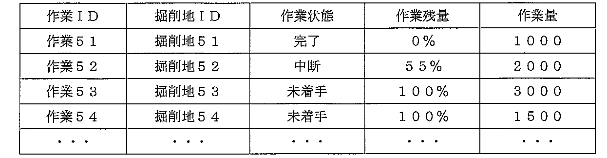
「作業ID」は、各作業を識別するためのIDであり、本実施形態において「作業ID」の番号の昇順で作業が実施されることを想定している。「掘削地ID」は、各掘削地51~54を識別するためのIDであり、「掘削地ID」には油圧ショベル1の掘削動作で作成したい3次元地形形状である設計地形6が紐づけられている。「作業状態」は、「完了」、「中断」、「実行中」、「未着手」の4つの状態が存在する。「作業残量」は、各作業の残量を表す百分率である。「作業量」は、「作業開始前から設計地形を作成するまでに掘削する必要がある土量」である。 The "work ID" is an ID for identifying each work, and it is assumed that the work is carried out in ascending order of the numbers of the "work ID" in the present embodiment. The "excavation site ID" is an ID for identifying each excavation site 51 to 54, and the "excavation site ID" is associated with the design terrain 6 which is a three-dimensional terrain shape to be created by the excavation operation of the hydraulic excavator 1. Has been done. There are four "working states": "completed", "suspended", "running", and "not started". The "remaining amount of work" is a percentage representing the remaining amount of each work. The "work amount" is the "soil amount that needs to be excavated from before the start of work until the design terrain is created".

「作業残量」は、「現在の地形から設計地形を作成するまでに掘削する必要がある土量」を「作業量」で除算し、百分率に換算した値である。「現在の地形から設計地形を作成するまでに掘削する必要がある土量」及び「作業開始前から設計地形を作成するまでに掘削する必要がある土量」は、作業状態管理部452において現況地形に基づいて体積として算出する。「作業残量」が0%に達した作業は「作業状態」が「完了」となる。「作業残量」が100%の作業は「作業状態」が「未着手」となる。「作業残量」が0%に達さずに中断した作業は「作業状態」が「中断」となる。また、油圧ショベル1に対し作業指示を行っている作業は「作業状態」が「実行中」となる。そして、この「作業残量」及び「作業状態」は作業の進捗状況を示すパラメータでもある。なお、作業DB456に記録された作業計画の「掘削地ID」に紐づけられた3次元地形形状である設計地形6は、モニタ42への入力を介して編集可能とされている。 The "remaining amount of work" is a value obtained by dividing "the amount of soil that needs to be excavated from the current terrain to creating the design terrain" by "the amount of work" and converting it into a percentage. "The amount of soil that needs to be excavated from the current terrain to create the design terrain" and "the amount of soil that needs to be excavated from before the start of work until the design terrain is created" are the current status in the work condition management unit 452. Calculated as volume based on terrain. When the "remaining amount of work" reaches 0%, the "working state" becomes "completed". When the "remaining amount of work" is 100%, the "working state" is "not started". If the "remaining amount of work" does not reach 0% and the work is interrupted, the "working state" becomes "interrupted". Further, the "working state" of the work for which the work instruction is given to the hydraulic excavator 1 is "execution". The "remaining amount of work" and "working state" are also parameters indicating the progress of the work. The design terrain 6 which is a three-dimensional terrain shape associated with the “excavation site ID” of the work plan recorded in the work DB 456 can be edited via input to the monitor 42.

[物体DB]
物体DB455は、特許請求の範囲に記載の「物体記録部」に相当するものであり、作業現場5に存在すると予想される予想存在物体の情報及び該予想存在物体以外の非予想存在物体の情報のうち、少なくとも一方を記録している。本実施形態において、物体DB455には、油圧ショベル1が作業現場5において作業を行う上で作業の阻害要素となり得る異常物体7(すなわち、予想存在物体)の情報が記録されている。具体的には、大きな石、水道管、降雨による広範囲のぬかるみといったものを、作業の阻害要素となり得る異常物体7としている。また、物体DB455には、異常物体7を物体検知技術で検知するために必要な特徴量として、3次元点群データが記録されている。なお、物体DB455には、作業を行う上で作業の阻害要素となり得ない異常物体(すなわち、非予想存在物体)の情報が記録されても良い。このようにすれば、様々な異常物体の検出に幅広く対応できる。
[Object DB]
The object DB 455 corresponds to the "object recording unit" described in the claims, and information on a predicted existing object expected to exist at the work site 5 and information on a non-predicted existing object other than the predicted existing object. At least one of them is recorded. In the present embodiment, the object DB 455 records information on the abnormal object 7 (that is, the expected existing object) that can be an obstacle to the work when the hydraulic excavator 1 performs the work at the work site 5. Specifically, large stones, water pipes, and a wide range of mud due to rainfall are designated as anomalous objects 7 that can be obstacles to work. Further, in the object DB 455, three-dimensional point cloud data is recorded as a feature amount necessary for detecting the abnormal object 7 by the object detection technique. In addition, the object DB 455 may record information on an abnormal object (that is, an unpredictable existing object) that cannot be an obstacle to the work in performing the work. By doing so, it is possible to widely cope with the detection of various abnormal objects.

[異常物体検知部]
異常物体検知部454は、レーザスキャナ34の計測結果に基づいて、上記作業計画を実施する作業現場に存在する異常物体を検知する。具体的には、異常物体検知部454は、まずレーザスキャナ34から3次元点群データを取得し、点群の3次元座標情報を用いて油圧ショベル1周囲の物体の位置及び形状の情報を取得する。ここで、物体の位置とは、検知された物体を計測した各点の3次元座標を用いて算出した点群重心座標である。物体の形状とは、各点の3次元座標からX、Y、Z座標それぞれの最大値から最小値までの距離を、奥行き、幅、高さとして算出した直方体である。物体の位置及び形状の検知手法としては、例えば既に知られたOGM(Occupancy Grid Map)法のような、3次元の点群から物体情報を取得できる手法であれば良い。
[Abnormal object detector]
The abnormal object detection unit 454 detects an abnormal object existing at the work site where the work plan is implemented, based on the measurement result of the laser scanner 34. Specifically, the abnormal object detection unit 454 first acquires 3D point cloud data from the laser scanner 34, and acquires information on the position and shape of an object around the hydraulic excavator 1 using the 3D point cloud information of the point cloud. do. Here, the position of the object is the coordinate of the center of gravity of the point cloud calculated by using the three-dimensional coordinates of each point measured by the detected object. The shape of an object is a rectangular parallelepiped obtained by calculating the distance from the maximum value to the minimum value of each of the X, Y, and Z coordinates from the three-dimensional coordinates of each point as the depth, width, and height. The method for detecting the position and shape of an object may be any method that can acquire object information from a three-dimensional point group, such as the already known OGM (Occupancy Grid Map) method.

次に、異常物体検知部454は、物体DB455に記録された3次元点群データである物体情報を習得し、レーザスキャナ34から取得した物体の中に物体情報として記録された異常物体7が存在するか否かを判定することで異常物体の検知を行う。具体的には、異常物体検知部454は、例えばDeep Learningを活用した物体検知技術であるSSD等を用いて、レーザスキャナ34から取得した物体の3次元点群データと、習得した物体情報の3次元点群データとの一致率に基づいて、作業現場5に存在する異常物体を検知する。そして、例えばその一致率が予め設定された閾値以上になった場合に、異常物体検知部454は該物体を異常物体7として検知する。異常物体検知部454は、検知した異常物体7の位置、形状及び種類を異常物体情報として作業状態管理部452に出力する。 Next, the abnormal object detection unit 454 acquires the object information which is the three-dimensional point group data recorded in the object DB 455, and the abnormal object 7 recorded as the object information exists in the object acquired from the laser scanner 34. Anomalous objects are detected by determining whether or not to do so. Specifically, the anomalous object detection unit 454 uses, for example, SSD, which is an object detection technology utilizing Deep Learning, to obtain 3D point group data of an object from the laser scanner 34 and 3 of the acquired object information. An abnormal object existing in the work site 5 is detected based on the matching rate with the three-dimensional point group data. Then, for example, when the matching rate becomes equal to or higher than a preset threshold value, the abnormal object detection unit 454 detects the object as the abnormal object 7. The abnormal object detection unit 454 outputs the position, shape and type of the detected abnormal object 7 to the work state management unit 452 as abnormal object information.

[演算部]
演算部453は、計測データ処理部451と電気的に接続され、上部旋回体3の傾斜角度及び位置、方位、旋回角度、作業機各部の姿勢、現況地形の演算結果を計測データ処理部451から取得する。また、この演算部453は、切替スイッチ43から油圧ショベル1が有人操作状態であるか又は無人自動運転状態であるかを取得し、有人操作状態又は無人自動運転状態に応じて演算等の処理を行う。
[Calculation unit]
The calculation unit 453 is electrically connected to the measurement data processing unit 451 and calculates the inclination angle and position of the upper swivel body 3, the direction, the turning angle, the posture of each part of the working machine, and the calculation result of the current terrain from the measurement data processing unit 451. get. Further, the calculation unit 453 acquires from the changeover switch 43 whether the hydraulic excavator 1 is in the manned operation state or the unmanned automatic operation state, and performs processing such as calculation according to the manned operation state or the unmanned automatic operation state. conduct.

例えば油圧ショベル1が無人自動運転状態である場合、演算部453は、作業状態管理部452から動作計画を取得し、取得した動作計画に基づいて下部走行体4の目標軌跡、バケット先端27の目標軌跡及び各アクチュエータ(各油圧シリンダ23、各油圧モータ26)の目標動作速度等を演算し、演算した結果を作業状態管理部452に出力する。なお、動作計画には、現況地形上におけるバケット先端27の接地位置が少なくとも含まれている。 For example, when the hydraulic excavator 1 is in an unmanned automatic operation state, the calculation unit 453 acquires an operation plan from the work state management unit 452, and based on the acquired operation plan, the target locus of the lower traveling body 4 and the target of the bucket tip 27. The locus and the target operating speed of each actuator (each hydraulic cylinder 23, each hydraulic motor 26) are calculated, and the calculated result is output to the work state management unit 452. The motion plan includes at least the ground contact position of the bucket tip 27 on the current terrain.

具体的には、演算部453は、まず計測データ処理部451から取得した演算結果に基づいて、バケット先端27を現在地点から動作計画に含まれた指定位置に接地できる地点まで移動するための下部走行体4の目標軌跡を演算する。次に、演算部453は、バケット先端27を作業状態管理部452で指定された接地位置まで移動させてバケット22内に土を格納するまでの、バケット先端27の目標軌跡を演算する。 Specifically, the calculation unit 453 first moves the bucket tip 27 from the current position to a point where it can be grounded to a designated position included in the motion plan based on the calculation result acquired from the measurement data processing unit 451. The target locus of the traveling body 4 is calculated. Next, the calculation unit 453 calculates the target locus of the bucket tip 27 until the bucket tip 27 is moved to the ground contact position designated by the work state management unit 452 and the soil is stored in the bucket 22.

また、演算部453は、油圧ショベル1が放土地50に放土するまでの下部走行体4の目標軌跡及びバケット先端27の目標軌跡をそれぞれ演算する。なお、演算部453は、演算した下部走行体4の目標軌跡及びバケット先端27の目標軌跡をグローバル座標系を基準として作成する。更に、演算部453は、演算した下部走行体4の目標軌跡とバケット先端27の目標軌跡とに基づき、車体を動作させるために必要な各アクチュエータ(各油圧シリンダ23、各油圧モータ26)の目標動作速度を演算する。そして、演算部453は演算した結果を作業状態管理部452に出力する。 Further, the calculation unit 453 calculates the target locus of the lower traveling body 4 and the target locus of the bucket tip 27 until the hydraulic excavator 1 releases the soil to the release land 50, respectively. The calculation unit 453 creates the calculated target locus of the lower traveling body 4 and the target locus of the bucket tip 27 with reference to the global coordinate system. Further, the calculation unit 453 is a target of each actuator (each hydraulic cylinder 23, each hydraulic motor 26) necessary for operating the vehicle body based on the calculated target locus of the lower traveling body 4 and the target locus of the bucket tip 27. Calculate the operating speed. Then, the calculation unit 453 outputs the calculation result to the work state management unit 452.

一方、油圧ショベル1が有人操作状態である場合、演算部453は、作業状態管理部452から動作計画を取得せず、下部走行体4の目標軌跡、バケット先端27の目標軌跡、及び各アクチュエータ(各油圧シリンダ23、各油圧モータ26)の目標動作速度の演算を行わない。 On the other hand, when the hydraulic excavator 1 is in the manned operation state, the calculation unit 453 does not acquire the operation plan from the work state management unit 452, and the target locus of the lower traveling body 4, the target locus of the bucket tip 27, and each actuator ( The target operating speed of each hydraulic cylinder 23 and each hydraulic motor 26) is not calculated.

[作業状態管理部]
作業状態管理部452は、油圧ショベル1の作業状態を管理するように、作業DB456に記録された作業計画中の作業順序に沿って作業内容を選択し、選択した作業内容とレーザスキャナ34の計測結果等に基づいて油圧ショベル1の動作計画を作成する。
[Work status management department]
The work state management unit 452 selects work contents according to the work order in the work plan recorded in the work DB 456 so as to manage the work state of the hydraulic excavator 1, and measures the selected work contents and the laser scanner 34. Create an operation plan for the hydraulic excavator 1 based on the results and the like.

具体的には、作業状態管理部452は、異常物体検知部454、作業DB456及び計測データ処理部451とそれぞれ電気的に接続され、異常物体検知部454から検知結果(例えば、異常物体の情報)と、作業DB456から作業計画と、計測データ処理部451から現況地形をそれぞれ取得する。作業状態管理部452は、まず作業DB456から取得した作業計画に基づいて、例えば作業計画中の作業順序に沿って作業内容を順次に選択する。次に、作業状態管理部452は、選択した作業内容について、少なくともバケット先端27の接地位置を含む動作計画を作成する。 Specifically, the work state management unit 452 is electrically connected to the abnormal object detection unit 454, the work DB 456, and the measurement data processing unit 451, respectively, and the detection result (for example, information on the abnormal object) is detected from the abnormal object detection unit 454. Then, the work plan is acquired from the work DB 456, and the current terrain is acquired from the measurement data processing unit 451. The work state management unit 452 first sequentially selects work contents according to, for example, the work order in the work plan, based on the work plan acquired from the work DB 456. Next, the work state management unit 452 creates an operation plan including at least the grounding position of the bucket tip 27 for the selected work content.

次に、作業状態管理部452は、作成した動作計画を演算部453に出力し、該動作計画に基づいたバケット先端27の目標軌跡、下部走行体4の目標軌跡及び各アクチュエータの目標動作速度の演算を演算部453に指示する。次に、作業状態管理部452は、演算部453からバケット先端27の目標軌跡、下部走行体4の目標軌跡及び各アクチュエータの目標動作速度の演算結果を取得する。 Next, the work state management unit 452 outputs the created motion plan to the calculation unit 453, and the target locus of the bucket tip 27, the target locus of the lower traveling body 4, and the target motion speed of each actuator based on the motion plan. The calculation is instructed to the calculation unit 453. Next, the work state management unit 452 acquires the calculation results of the target locus of the bucket tip 27, the target locus of the lower traveling body 4, and the target operating speed of each actuator from the calculation unit 453.

また、作業状態管理部452は、異常物体検知部454から取得した検知結果(例えば、異常物体の情報)と、演算部453から取得したバケット先端27の目標軌跡及び下部走行体4の目標軌跡とに基づいて、異常物体検知部454により検知された異常物体の存在によって上記動作計画の実施が阻害される否かを判定する。 Further, the work state management unit 452 includes the detection result (for example, information on the abnormal object) acquired from the abnormal object detection unit 454, the target locus of the bucket tip 27 acquired from the calculation unit 453, and the target locus of the lower traveling body 4. Based on the above, it is determined whether or not the implementation of the operation plan is hindered by the presence of the abnormal object detected by the abnormal object detection unit 454.

そして、作業現場5上にバケット先端27の目標軌跡及び下部走行体4の目標軌跡のいずれも阻害する異常物体が存在しない場合、作業状態管理部452は、該異常物体の存在によって前記動作計画の実施が阻害されないと判定する。このとき、作業状態管理部452は、演算部453から取得した各アクチュエータ(各油圧シリンダ23、各油圧モータ26)の目標動作速度を作業状態管理情報として車体コントローラ41の車体制御部411に出力する。ここでの作業状態管理情報は、すなわち制御信号である。 When there is no abnormal object on the work site 5 that obstructs both the target locus of the bucket tip 27 and the target locus of the lower traveling body 4, the work state management unit 452 determines the operation plan due to the presence of the abnormal object. Determine that implementation is not hindered. At this time, the work state management unit 452 outputs the target operating speed of each actuator (each hydraulic cylinder 23, each hydraulic motor 26) acquired from the calculation unit 453 to the vehicle body control unit 411 of the vehicle body controller 41 as work state management information. .. The work state management information here is, that is, a control signal.

一方、作業現場5上にバケット先端27の目標軌跡及び下部走行体4の目標軌跡の少なくとも一方を阻害する異常物体が存在する場合、作業状態管理部452は、該異常物体の存在によって動作計画の実施が阻害されると判定する。このとき、作業状態管理部452は、車体制御部411に対し実施中の作業の中断を指示する。次に、作業状態管理部452は、中断した作業(すなわち、阻害される作業)を「異常物体を含む範囲」と「異常物体を含まない範囲」で実施される作業に分割可能か否かを更に判定する。 On the other hand, when there is an abnormal object on the work site 5 that obstructs at least one of the target locus of the bucket tip 27 and the target locus of the lower traveling body 4, the work state management unit 452 determines the operation plan by the presence of the abnormal object. It is determined that the implementation is hindered. At this time, the work state management unit 452 instructs the vehicle body control unit 411 to suspend the work being performed. Next, the work state management unit 452 determines whether or not the interrupted work (that is, the work to be hindered) can be divided into the work performed in the "range including the abnormal object" and the work performed in the "range not including the abnormal object". Further determine.

そして、中断した作業を「異常物体を含む範囲」と「異常物体を含まない範囲」で実施される作業に分割可能であると判定した場合、作業状態管理部452は、「異常物体を含まない範囲」の作業内容を選択し、該「異常物体を含まない範囲」において新たな作業計画を作成し、作業DB456に追加する。その後、作業状態管理部452は、「異常物体を含まない範囲」でのバケット先端27の接地位置を新たな動作計画として演算部453に出力し、該動作計画に基づいたバケット先端27の目標軌跡、下部走行体4の目標軌跡及び各アクチュエータの目標動作速度の演算を演算部453に指示する。言い換えれば、作業状態管理部452は、「異常物体を含まない範囲」での作業を実施するためのバケット先端27の目標軌跡、下部走行体4の目標軌跡、及び各アクチュエータ(各油圧シリンダ23、各油圧モータ26)の目標動作速度の演算を演算部453に求める。 Then, when it is determined that the interrupted work can be divided into the work to be performed in the "range including the abnormal object" and the "range not including the abnormal object", the work state management unit 452 "does not include the abnormal object". Select the work content of "range", create a new work plan in the "range not including abnormal objects", and add it to the work DB 456. After that, the work state management unit 452 outputs the ground contact position of the bucket tip 27 in the "range not including the abnormal object" to the calculation unit 453 as a new operation plan, and the target locus of the bucket tip 27 based on the operation plan. , The calculation unit 453 is instructed to calculate the target locus of the lower traveling body 4 and the target operating speed of each actuator. In other words, the work state management unit 452 has a target locus of the bucket tip 27 for carrying out work in the "range not including abnormal objects", a target locus of the lower traveling body 4, and each actuator (each hydraulic cylinder 23, The calculation unit 453 is requested to calculate the target operating speed of each hydraulic motor 26).

なお、作業状態管理部452は、作業DB456に記録された作業計画に実施可能な作業が存在しない場合、車体制御部411に対し作業終了を指示する。 If there is no feasible work in the work plan recorded in the work DB 456, the work state management unit 452 instructs the vehicle body control unit 411 to end the work.

以下、図5~図7を基に異常物体7が検知された作業現場5において、「異常物体7を含む範囲」と「異常物体7を含まない範囲」に分割する例を詳細に説明する。 Hereinafter, an example of dividing into a “range including the abnormal object 7” and a “range not including the abnormal object 7” in the work site 5 where the abnormal object 7 is detected based on FIGS. 5 to 7 will be described in detail.

図5~図7では、異常物体検知部454によって異常物体7が検知された「掘削地i」を示している。また、図5~図7では、作業現場5上のある点を原点とすることで図示する方向にXYZ空間の現場固有の座標系を定義しており、グローバル座標系で扱われる計測データ処理部451の各演算結果と演算部453により演算された各目標軌跡とは、現場固有の座標系にそれぞれ変換される。 5 to 7 show the “excavation site i” in which the abnormal object 7 is detected by the abnormal object detection unit 454. Further, in FIGS. 5 to 7, a coordinate system peculiar to the site in the XYZ space is defined in the direction shown by setting a certain point on the work site 5 as the origin, and the measurement data processing unit handled by the global coordinate system is used. Each calculation result of 451 and each target locus calculated by the calculation unit 453 are converted into a coordinate system peculiar to the site.

図5は作業現場5の平面図であり、図6及び図7は図5中の矢印に沿った作業現場5の側面図である。図6及び図7に示すように、「掘削地i」の現況地形は斜面72と平面73で構成されている。本実施形態では、異常物体7は作業開始時に斜面72から露出していることを想定する。図6に示すように、「掘削地i」では、設計地形6で示される深さまでの掘削が油圧ショベル1によって実施される。 5 is a plan view of the work site 5, and FIGS. 6 and 7 are side views of the work site 5 along the arrows in FIG. As shown in FIGS. 6 and 7, the current topography of the “excavation site i” is composed of a slope 72 and a plane 73. In the present embodiment, it is assumed that the abnormal object 7 is exposed from the slope 72 at the start of work. As shown in FIG. 6, in the “excavation site i”, excavation to the depth indicated by the design terrain 6 is carried out by the hydraulic excavator 1.

図5~図7に示すように、「掘削地i」において演算部453により演算されたバケット先端27の目標軌跡(図中の破線部分参照)は、異常物体7の位置と重なっており、油圧ショベル1は作業を継続できない状態となっている。なお、本実施形態でいう異常物体7は、油圧ショベル1の作業を阻害する程度の大きさ(例えば大きな石)を有するものを指しており、従って比較的に小さい石のような異常物体が検知されても、実際に作業の阻害にならない。 As shown in FIGS. 5 to 7, the target locus of the bucket tip 27 calculated by the calculation unit 453 in the “excavation site i” (see the broken line portion in the figure) overlaps with the position of the abnormal object 7, and is hydraulically driven. The excavator 1 is in a state where the work cannot be continued. The abnormal object 7 in the present embodiment refers to an object having a size (for example, a large stone) that hinders the work of the hydraulic excavator 1, and therefore an abnormal object such as a relatively small stone is detected. Even if it is done, it does not actually hinder the work.

本実施形態では、「掘削地i」において演算部453により演算された目標軌跡上に異常物体7が存在するため作業を継続できない場合においても、作業状態管理部452は、「掘削地i」を「異常物体7を含む範囲」である「掘削地i_1」と「異常物体7を含まない範囲」である「掘削地i_2」に更に分割し、「異常物体7を含まない範囲」における作業状態管理情報を車体制御部411に指令することにより、油圧ショベル1による作業を継続させることができる。 In the present embodiment, even when the work cannot be continued because the abnormal object 7 exists on the target locus calculated by the calculation unit 453 in the “excavation site i”, the work state management unit 452 sets the “excavation site i”. It is further divided into "excavation site i_1" which is "range including abnormal object 7" and "excavation site i_2" which is "range not including abnormal object 7", and work state management in "range not including abnormal object 7". By commanding the information to the vehicle body control unit 411, the work by the hydraulic excavator 1 can be continued.

[車体制御部]
車体制御部411は、作業状態管理部452により作成された動作計画に基づいて油圧ショベル1の動作を制御する。図4に示すように、車体制御部411は、切替スイッチ43と電気的に接続され、切替スイッチ43から油圧ショベル1が有人操作状態であるか又は無人自動運転状態であるかを取得する。また、車体制御部411は、作業状態管理部452と電気的に接続され、作業状態管理部452から上述の作業状態管理情報を取得する。
[Body control unit]
The vehicle body control unit 411 controls the operation of the hydraulic excavator 1 based on the operation plan created by the work state management unit 452. As shown in FIG. 4, the vehicle body control unit 411 is electrically connected to the changeover switch 43, and acquires from the changeover switch 43 whether the hydraulic excavator 1 is in the manned operation state or the unmanned automatic operation state. Further, the vehicle body control unit 411 is electrically connected to the work state management unit 452, and acquires the above-mentioned work state management information from the work state management unit 452.

そして、油圧ショベル1が有人操作状態である場合、車体制御部411は、操作レバー30の操作量に応じて各アクチュエータを動作させるよう制御弁55を駆動する。一方、油圧ショベル1が無人自動運転状態である場合、車体制御部411は、作業状態管理部452から作業状態管理情報として取得した各アクチュエータの目標動作速度に応じて、各アクチュエータを動作させるよう制御弁55を駆動させる。そして、車体制御部411は、作業状態管理部452から全作業の終了が出力された場合、油圧ショベル1の動作を即時停止、あるいは予め指定された位置まで油圧ショベル1を移動させてから動作を停止する。なお、車体制御部411は、作業状態管理部452から全作業の終了が出力された場合、モニタ42に作業計画が終了したことを出力しても良い。 When the hydraulic excavator 1 is in a manned operation state, the vehicle body control unit 411 drives the control valve 55 to operate each actuator according to the operation amount of the operation lever 30. On the other hand, when the hydraulic excavator 1 is in the unmanned automatic operation state, the vehicle body control unit 411 controls to operate each actuator according to the target operating speed of each actuator acquired as work state management information from the work state management unit 452. Drive the valve 55. Then, when the work state management unit 452 outputs the end of all work, the vehicle body control unit 411 immediately stops the operation of the hydraulic excavator 1 or moves the hydraulic excavator 1 to a position designated in advance and then operates the hydraulic excavator 1. Stop. When the work state management unit 452 outputs the end of all the work, the vehicle body control unit 411 may output to the monitor 42 that the work plan is completed.

以下、図8及び図9を参照して自動作業システム10の制御処理について説明する。図8は制御処理のステップS10~ステップS21を示すフローチャートであり、図9は制御処理のステップS22~ステップS27を示すフローチャートである。 Hereinafter, the control process of the automatic work system 10 will be described with reference to FIGS. 8 and 9. FIG. 8 is a flowchart showing steps S10 to S21 of the control process, and FIG. 9 is a flowchart showing steps S22 to S27 of the control process.

まず、ステップS10では、作業ID番号(作業i)が付与される。ここでは、「i」を例えば51とする。 First, in step S10, a work ID number (work i) is assigned. Here, "i" is set to 51, for example.

ステップS10に続くステップS11では、作業状態管理部452は、作業DB456に記録されている作業計画から「作業i」の情報を取得する。具体的には、作業状態管理部452は、作業IDが「作業i」である作業に関する「掘削地ID」、「作業状態」、「作業残量」及び「作業量」を取得する。 In step S11 following step S10, the work state management unit 452 acquires the information of "work i" from the work plan recorded in the work DB 456. Specifically, the work state management unit 452 acquires the "excavation site ID", "work state", "remaining amount of work", and "work amount" related to the work whose work ID is "work i".

ステップS11に続くステップS12では、作業状態管理部452は、演算部453に対し、取得した「作業i」の情報の中から「掘削地i」の情報を出力する。具体的には、作業状態管理部452は、「掘削地i」と紐づけられた設計地形を演算部453に出力する。「掘削地i」と紐づけられた設計地形は、油圧ショベル1がこれから掘削で作成したい3次元地形の形状である。 In step S12 following step S11, the work state management unit 452 outputs the information of the "excavation site i" from the acquired information of the "work i" to the calculation unit 453. Specifically, the work state management unit 452 outputs the design terrain associated with the “excavation site i” to the calculation unit 453. The design terrain associated with "excavation site i" is the shape of the three-dimensional terrain that the hydraulic excavator 1 wants to create by excavation.

ステップS12に続くステップS13では、作業状態管理部452は、まず作成した動作計画を演算部453に出力し、該動作計画に基づいたバケット先端27の目標軌跡、下部走行体4の目標軌跡、及び各アクチュエータ(各油圧シリンダ23、各油圧モータ26)の目標動作速度を演算するように演算部453に指示する。次に、演算部453は、動作計画に基づいてバケット先端27の目標軌跡、下部走行体4の目標軌跡及び各アクチュエータの目標動作速度をそれぞれ演算し、演算した結果を作業状態管理部452に出力する。これによって、作業状態管理部452は、上記の演算結果を取得する。 In step S13 following step S12, the work state management unit 452 first outputs the created operation plan to the calculation unit 453, and the target locus of the bucket tip 27, the target locus of the lower traveling body 4, and the target locus of the lower traveling body 4 based on the operation plan. The calculation unit 453 is instructed to calculate the target operating speed of each actuator (each hydraulic cylinder 23, each hydraulic motor 26). Next, the calculation unit 453 calculates the target locus of the bucket tip 27, the target locus of the lower traveling body 4, and the target operation speed of each actuator based on the operation plan, and outputs the calculated result to the work state management unit 452. do. As a result, the work state management unit 452 acquires the above calculation result.

ステップS13に続くステップS14では、作業状態管理部452は、異常物体検知部454から異常物体情報を取得する。ステップS14に続くステップS15では、作業状態管理部452は、「作業i」の動作計画を阻害する異常物体が存在するか否かを判定する。このとき、作業状態管理部452は、ステップS13で取得したバケット先端27の目標軌跡及び下部走行体4の走行軌跡といった車体の3次元目標軌跡と、ステップS14で取得した異常物体情報とに基づいて、車体の3次元目標軌跡上に異常物体情報に記載された物体(すなわち、異常物体)が存在するか否かを判定する。 In step S14 following step S13, the work state management unit 452 acquires the abnormal object information from the abnormal object detection unit 454. In step S15 following step S14, the work state management unit 452 determines whether or not there is an abnormal object that obstructs the operation plan of "work i". At this time, the work state management unit 452 is based on the three-dimensional target locus of the vehicle body such as the target locus of the bucket tip 27 and the travel locus of the lower traveling body 4 acquired in step S13, and the abnormal object information acquired in step S14. , It is determined whether or not the object described in the abnormal object information (that is, the abnormal object) exists on the three-dimensional target locus of the vehicle body.

そして、車体の3次元目標軌跡上に異常物体が存在すると判定された場合、制御処理はステップS22に進む。例えば、図5に示す作業現場5のように、現場固有の現場座標系においてバケット先端27の目標軌跡上に異常物体7が存在した場合、制御処理はステップS22に進むことになる。一方、車体の3次元目標軌跡上に異常物体が存在しないと判定された場合、制御処理はステップS16に進む。 Then, when it is determined that an abnormal object exists on the three-dimensional target locus of the vehicle body, the control process proceeds to step S22. For example, when the abnormal object 7 exists on the target locus of the bucket tip 27 in the site coordinate system peculiar to the site as in the work site 5 shown in FIG. 5, the control process proceeds to step S22. On the other hand, if it is determined that no abnormal object exists on the three-dimensional target locus of the vehicle body, the control process proceeds to step S16.

ステップS16では、作業状態管理部452は、車体制御部411に対し作業状態管理情報として出力する。具体的には、作業状態管理部452は、ステップS13で取得した各アクチュエータの目標動作速度を車体制御部411に出力する。そして、車体制御部411は、各アクチュエータの目標動作速度に従って各アクチュエータを動作させる。これによって、油圧ショベル1が自動運転で作業を行う。 In step S16, the work state management unit 452 outputs the work state management information to the vehicle body control unit 411. Specifically, the work state management unit 452 outputs the target operating speed of each actuator acquired in step S13 to the vehicle body control unit 411. Then, the vehicle body control unit 411 operates each actuator according to the target operating speed of each actuator. As a result, the hydraulic excavator 1 performs the work by automatic operation.

ステップS16に続くステップS17では、作業状態管理部452は、「作業i」の「作業残量」を算出し、作業DB456を更新する。具体的には、作業状態管理部452は、作業DB456に記録された「掘削地i」の設計地形と計測データ処理部451から取得した現況地形の3次元情報の差分から「作業i」の「進捗状況」を算出し、作業DBに記録された「作業i」の「作業残量」を更新する。 In step S17 following step S16, the work state management unit 452 calculates the "remaining amount of work" of "work i" and updates the work DB 456. Specifically, the work state management unit 452 "work i" "work i" from the difference between the design terrain of the "excavation site i" recorded in the work DB 456 and the three-dimensional information of the current terrain acquired from the measurement data processing unit 451. The "progress status" is calculated, and the "remaining amount of work" of "work i" recorded in the work DB is updated.

ステップS17に続くステップS18では、作業状態管理部452は、ステップS17で算出した「作業i」の「作業残量」が0%に達しているか否かを判定する。0%に達していると判定された場合、制御処理はステップS19に進む。一方、0%に達していないと判定された場合、制御処理はステップS11に戻る。 In step S18 following step S17, the work state management unit 452 determines whether or not the "remaining amount of work" of "work i" calculated in step S17 has reached 0%. If it is determined that the percentage has reached 0%, the control process proceeds to step S19. On the other hand, if it is determined that the percentage has not reached 0%, the control process returns to step S11.

ステップS19では、作業状態管理部452は、作業DB456に記録された「作業i」の「作業状態」を「完了」に更新する。 In step S19, the work state management unit 452 updates the "work state" of the "work i" recorded in the work DB 456 to "completed".

ステップS19に続くステップS20では、作業状態管理部452は、作業DB456に記憶された作業計画において、「作業状態」に「未着手」の作業が存在するか否かを判定する。「未着手」の作業が存在すると判定した場合、制御処理はステップS21に進む。ステップS21では、i=i+1(すなわち、i=52)と更新される。その後、制御処理はステップS11に戻る。一方、「作業状態」が「未着手」の作業が存在しないと判定した場合、作業状態管理部452は、全作業の終了を車体制御部411に指示する。これによって、一連の制御処理が終了する。 In step S20 following step S19, the work state management unit 452 determines whether or not there is an "unstarted" work in the "work state" in the work plan stored in the work DB 456. If it is determined that there is an "unstarted" operation, the control process proceeds to step S21. In step S21, it is updated as i = i + 1 (that is, i = 52). After that, the control process returns to step S11. On the other hand, when it is determined that there is no work whose "work state" is "not started", the work state management unit 452 instructs the vehicle body control unit 411 to end all the work. This ends a series of control processes.

上述したように、ステップS15で異常物体が存在すると判定された場合、制御処理はステップS22に進む。ステップS22では、作業状態管理部452は、「掘削地i」を「阻害要素が存在する範囲」(すなわち、異常物体を含む範囲)と「阻害要素が存在しない範囲」(すなわち、異常物体を含まない範囲)に分割可能か否かを判定する。具体的には、作業状態管理部452は、作業DB456に記録された図6に示す「作業i」の「掘削地i」を、図7に示すように「異常物体7を含む範囲」である「掘削地i_1」と「異常物体7を含まない範囲」である「掘削地i_2」に分割できるか否かを判定する。 As described above, when it is determined in step S15 that an abnormal object exists, the control process proceeds to step S22. In step S22, the work state management unit 452 sets the "excavation site i" as "a range in which an obstructive element exists" (that is, a range including an abnormal object) and "a range in which an obstructive element does not exist" (that is, includes an abnormal object). It is determined whether or not it can be divided into (no range). Specifically, the work state management unit 452 sets the "excavation site i" of the "work i" shown in FIG. 6 recorded in the work DB 456 to the "range including the abnormal object 7" as shown in FIG. It is determined whether or not it can be divided into "excavation site i_1" and "excavation site i_2" which is a "range not including the abnormal object 7".

例えば図7に示す例では、異常物体7が作業現場5の斜面72から出土したため、作業状態管理部452はY軸方向に沿って、斜面72部分を「掘削地i_1」として、平面73部分を「掘削地i_2」としてそれぞれ分割する。そして、「異常物体7を含む範囲」である「掘削地i_1」は、図5に示すX、Y座標において、異常物体7に対し「一定のマージン」を持つ長方形範囲形状として切り出される。該「一定のマージン」は、異常物体情報に記載された異常物体7の種類に基づき決定されても良く、予め全ての異常物体7に共通する一定値として決定されても良い。「掘削地i」から「掘削地i_1」を切り出した結果、「異常物体7を含まない範囲」である「掘削地i_2」が図5、図7に示す範囲で生じる。 For example, in the example shown in FIG. 7, since the abnormal object 7 was excavated from the slope 72 of the work site 5, the work state management unit 452 set the slope 72 as “excavation site i_1” along the Y-axis direction, and set the plane 73 as “excavation site i_1”. Divide each as "excavation site i_2". Then, the "excavation site i_1", which is the "range including the abnormal object 7," is cut out as a rectangular range shape having a "constant margin" with respect to the abnormal object 7 at the X and Y coordinates shown in FIG. The "constant margin" may be determined based on the type of the abnormal object 7 described in the abnormal object information, or may be determined in advance as a constant value common to all the abnormal objects 7. As a result of cutting out the "excavation site i_1" from the "excavation site i", the "excavation site i_2" which is the "range not including the abnormal object 7" is generated in the range shown in FIGS. 5 and 7.

なお、「掘削地i」を「掘削地i_1」と「掘削地i_2」に分割可能か否かの判定は、例えば予め「作業量」に基づいて閾値を決めておき、「掘削地i_2」が該閾値以上である場合に分割可能、該閾値より小さい場合に分割不可と判定する。 For the determination of whether or not the "excavation site i" can be divided into the "excavation site i_1" and the "excavation site i_2", for example, a threshold value is determined in advance based on the "work amount", and the "excavation site i_2" determines. When it is equal to or more than the threshold value, it is determined that it can be divided, and when it is smaller than the threshold value, it is determined that it cannot be divided.

そして、ステップS22で分割不可と判定された場合、処理はステップS23に進む。ステップS23では、作業状態管理部452は「作業i」の「作業状態」を「中断」に変更する。その後、制御処理はステップS20に戻る。 Then, if it is determined in step S22 that the division is not possible, the process proceeds to step S23. In step S23, the work state management unit 452 changes the "work state" of "work i" to "suspended". After that, the control process returns to step S20.

一方、ステップS22で分割可能と判定された場合、制御処理はステップS24に進む。ステップS24では、作業状態管理部452は、作業DB456に記録された「作業i」の「掘削地i」に対し、「阻害要素が存在する範囲」に「掘削地i_1」、「阻害要素が存在しない範囲」に「掘削地i_2」という名称の掘削地IDをそれぞれ付与する。すなわち、作業状態管理部452は、「異常物体7を含む範囲」に「掘削地i_1」、「異常物体7を含まない範囲」に「掘削地i_2」という名称の掘削地IDをそれぞれ付与する。 On the other hand, if it is determined in step S22 that the division is possible, the control process proceeds to step S24. In step S24, the work state management unit 452 has "excavation site i_1" and "inhibition element present" in the "range in which the obstruction element exists" with respect to the "excavation site i" of "work i" recorded in the work DB 456. An excavation site ID named "excavation site i_2" is assigned to each "range not to be excavated". That is, the work state management unit 452 assigns an excavation site ID named "excavation site i_1" to the "range including the abnormal object 7" and an excavation site ID named "excavation site i_2" to the "range not including the abnormal object 7".

ここでの処理は、例えば下記表2に示すように、「掘削地52」を「掘削地52_1」と「掘削地52_2」に分割可能と判定された場合、作業状態管理部452は、「異常物体7を含む範囲」に「掘削地52_1」、「異常物体7を含まない範囲」に「掘削地52_2」という名称の掘削地IDをそれぞれ付与する。 In the process here, for example, as shown in Table 2 below, when it is determined that the "excavation site 52" can be divided into the "excavation site 52_1" and the "excavation site 52_1", the work state management unit 452 "abnormality". An excavation site ID named "excavation site 52_1" is assigned to the "range including the object 7", and an excavation site ID named "excavation site 52_1" is assigned to the "range not including the abnormal object 7".

ステップS24に続くステップS25では、作業状態管理部452は、作業DB456に記録された「作業i」の作業IDを「作業i_1」、掘削地IDを「掘削地i_1」に更新し、作業状態を「中断」に変更する。ここでの処理は、例えば下記表2に示すように、作業状態管理部452は、作業DB456に記録された「作業52」の作業IDを「作業52_1」、掘削地IDを「掘削地52_1」に更新し、その作業状態を「中断」に変更する。 In step S25 following step S24, the work state management unit 452 updates the work ID of "work i" recorded in the work DB 456 to "work i_1" and the excavation site ID to "excavation site i_1", and changes the work state. Change to "suspended". In the processing here, for example, as shown in Table 2 below, the work state management unit 452 sets the work ID of "work 52" recorded in the work DB 456 to "work 52_1" and the excavation site ID to "excavation site 52_1". And change its working status to "suspended".

ステップS25に続くステップS26では、作業状態管理部452は、作業DB456の作業IDに「作業i_2」、掘削地IDに「掘削地i_2」、作業状態に「未着手」をそれぞれ追加する。ここでの処理は、例えば下記表2に示すように、作業状態管理部452は、作業DB456の作業IDに「作業52_2」、掘削地IDに「掘削地52_2」、作業状態に「未着手」をそれぞれ追加する。 In step S26 following step S25, the work state management unit 452 adds "work i_2" to the work ID of the work DB 456, "excavation site i_2" to the excavation site ID, and "not started" to the work state. In the processing here, for example, as shown in Table 2 below, the work state management unit 452 has the work ID of the work DB 456 as "work 52_2", the excavation site ID as "excavation site 52_2", and the work state as "not started". Are added respectively.

Figure 0007076020000003

ステップS26に続くステップS27では、作業ID番号(作業i)が「i_2」と更新される。その後、処理はステップS11に戻る。 In step S27 following step S26, the work ID number (work i) is updated to "i_2". After that, the process returns to step S11.

本実施形態の自動作業システム10では、異常物体7が検知されたとき、作業状態管理部452は、異常物体7の存在によって動作計画の実施が阻害される否かを判定し、異常物体7の存在によって動作計画の実施が阻害されると判定した場合に、「異常物体を含む範囲」と「異常物体7を含まない範囲」に分割可能か否かを更に判定する。そして、分割可能と判定した場合、作業状態管理部452は、「異常物体を含まない範囲」での作業を選択し、選択した作業の動作計画を作成して油圧ショベル1の自動運転による作業を継続させる。このようにすれば、作業現場5において油圧ショベル1の作業を阻害する異常物体7が出現した場合であっても、オペレータによる対処を必要とすることなく、作業状態管理部452は、実施可能な他の作業(すなわち、「異常物体7を含まない範囲」での作業)を選択することで自動運転による作業継続が可能となるので、生産性の低下を防止することができる。 In the automatic work system 10 of the present embodiment, when the abnormal object 7 is detected, the work state management unit 452 determines whether or not the presence of the abnormal object 7 hinders the implementation of the motion plan, and the abnormal object 7 When it is determined that the existence hinders the implementation of the motion plan, it is further determined whether or not it can be divided into a "range including an abnormal object" and a "range not including the abnormal object 7." Then, when it is determined that the work can be divided, the work state management unit 452 selects the work in the "range not including the abnormal object", creates an operation plan of the selected work, and performs the work by the automatic operation of the hydraulic excavator 1. To continue. By doing so, even if an abnormal object 7 that obstructs the work of the hydraulic excavator 1 appears at the work site 5, the work state management unit 452 can be implemented without requiring an operator to deal with it. By selecting another work (that is, work in the range not including the abnormal object 7), the work can be continued by the automatic operation, so that the decrease in productivity can be prevented.

[第2実施形態]
以下、図8、図10及び図11を参照して第2実施形態の自動作業システムを説明する。本実施形態の自動作業システムは、その構成が第1実施形態と同様であるが、制御処理において第1実施形態と異なっている。以下では、第1実施形態との相違点のみ説明する。
[Second Embodiment]
Hereinafter, the automatic work system of the second embodiment will be described with reference to FIGS. 8, 10 and 11. The automatic work system of the present embodiment has the same configuration as that of the first embodiment, but is different from the first embodiment in control processing. Hereinafter, only the differences from the first embodiment will be described.

すなわち、本実施形態では、作業現場5に油圧ショベル1の作業を阻害する異常物体7が存在する場合、作業管理者の選択操作によって油圧ショベル1が実施する作業の内容が決定される。また、作業状態管理部452は、作業管理者の承認を受けてから「異常物体7を含まない範囲」で作業を継続するための作業状態管理情報を車体制御部411に出力する。また、作業管理者の選択操作によって、油圧ショベル1の無人自動運転状態が有人操作状態に切り替えられる。更に、異常物体7が作業管理者によって作業現場5から取り除かれた後に、油圧ショベル1が有人操作状態から無人自動運転状態に切り替えられることで、油圧ショベル1の自動運転による作業が継続される。 That is, in the present embodiment, when the abnormal object 7 that obstructs the work of the hydraulic excavator 1 exists at the work site 5, the content of the work to be performed by the hydraulic excavator 1 is determined by the selection operation of the work manager. Further, the work state management unit 452 outputs the work state management information for continuing the work within the "range not including the abnormal object 7" to the vehicle body control unit 411 after receiving the approval of the work manager. Further, the unmanned automatic operation state of the hydraulic excavator 1 is switched to the manned operation state by the selection operation of the work manager. Further, after the abnormal object 7 is removed from the work site 5 by the work manager, the hydraulic excavator 1 is switched from the manned operation state to the unmanned automatic operation state, so that the work by the automatic operation of the hydraulic excavator 1 is continued.

作業管理者は、モニタ42及び切替スイッチ43の使用方法を習得している者であれば良い。また、作業管理者は、上部旋回体3の運転室内部、あるいは作業現場5の内外において油圧ショベル1の作業を監視できる場所に存在すれば良い。更に、モニタ42及び切替スイッチ43は、作業管理者が視認や操作できる場所に配置されれば良い。 The work manager may be a person who has mastered how to use the monitor 42 and the changeover switch 43. Further, the work manager may be present in the cab of the upper swing body 3 or in a place where the work of the hydraulic excavator 1 can be monitored inside and outside the work site 5. Further, the monitor 42 and the changeover switch 43 may be arranged in a place where the work manager can visually recognize and operate the monitor 42.

第2実施形態の自動作業システムの制御処理において、ステップS10~ステップS27は第1実施形態と同じであり、ステップS28~ステップS37は新たに加えた処理である。以下では、図10を基に新たに加えたステップS28~ステップS37のみ説明する。また本実施形態において、異常物体検知部454は、レーザスキャナ34の計測結果に基づいて油圧ショベル1の周囲に人が存在するか否かを判定し、人が存在すると判定した場合にその旨を作業状態管理部452に出力する。 In the control process of the automatic work system of the second embodiment, steps S10 to S27 are the same as those of the first embodiment, and steps S28 to S37 are newly added processes. In the following, only steps S28 to S37 newly added based on FIG. 10 will be described. Further, in the present embodiment, the abnormal object detection unit 454 determines whether or not there is a person around the hydraulic excavator 1 based on the measurement result of the laser scanner 34, and if it is determined that there is a person, that fact is determined. It is output to the work state management unit 452.

図10に示すように、ステップS22において「掘削地i」を「阻害要素が存在する範囲」と「阻害要素が存在しない範囲」に分割不可と判定された場合、制御処理は第1実施形態と同様にステップS23に進み、「作業i」の「作業状態」が「中断」への変更が行われる。その後、制御処理はステップS20に戻る。 As shown in FIG. 10, when it is determined in step S22 that the “excavation site i” cannot be divided into the “range in which the obstructing element exists” and the “range in which the obstructing element does not exist”, the control process is the same as that of the first embodiment. Similarly, the process proceeds to step S23, and the "work state" of "work i" is changed to "suspended". After that, the control process returns to step S20.

一方、ステップS22において「掘削地i」を「阻害要素が存在する範囲」と「阻害要素が存在しない範囲」に分割可能と判定された場合、制御処理はステップS28に進む。ステップS28では、作業状態管理部452は、図11に示すように作業を阻害する異常物体7に関する異常物体情報をモニタ42に表示することで、作業管理者に異常物体7の出現を知らせる。更に作業状態管理部452は、図11に示すようにモニタ42上に「異常物体7を含む範囲」である「掘削地i_1」と「異常物体7を含まない範囲」である「掘削地i_2」をモニタ42上に表示し、作業管理者に「掘削地i_1」と「掘削地i_2」に分割可能であることを知らせる。 On the other hand, if it is determined in step S22 that the "excavation site i" can be divided into a "range in which the obstructing element exists" and a "range in which the obstructing element does not exist", the control process proceeds to step S28. In step S28, the work state management unit 452 notifies the work manager of the appearance of the abnormal object 7 by displaying the abnormal object information regarding the abnormal object 7 that obstructs the work on the monitor 42 as shown in FIG. Further, as shown in FIG. 11, the work state management unit 452 has the “excavation site i_1” which is the “range including the abnormal object 7” and the “excavation site i_2” which is the “range not including the abnormal object 7” on the monitor 42. Is displayed on the monitor 42 to inform the work manager that it can be divided into "excavation site i_1" and "excavation site i_2".

ステップS28に続くステップS29では、作業管理者は、分割された「掘削地i_2」において、作業を継続するか否かをモニタ42を介して選択する(図11参照)。作業管理者により作業を継続すると選択された場合、制御処理は上述のステップS24に進む。一方、作業を継続しないと選択された場合、処理はステップS30に進む。 In step S29 following step S28, the work manager selects whether or not to continue the work in the divided “excavation site i_2” via the monitor 42 (see FIG. 11). If the work manager chooses to continue the work, the control process proceeds to step S24 described above. On the other hand, if it is selected not to continue the work, the process proceeds to step S30.

ステップS30では、作業管理者は、異常物体7を作業現場5から排除するか否かをモニタ42を介して選択する(図11参照)。異常物体を排除しないと選択された場合、制御処理は上述のステップS23に進む。一方、作業管理者により異常物体を排除すると選択された場合、制御処理はステップS31に進む。 In step S30, the work manager selects whether or not to exclude the abnormal object 7 from the work site 5 via the monitor 42 (see FIG. 11). If it is selected not to eliminate the anomalous object, the control process proceeds to step S23 described above. On the other hand, if the work manager selects to eliminate the abnormal object, the control process proceeds to step S31.

ステップS31では、作業管理者は、切替スイッチ43を操作することで、油圧ショベル1を無人自動運転状態から有人操作状態に切り替える。ステップS31に続くステップS32では、作業状態管理部452は、有人操作状態の解除パスワードを発行し、モニタ42を介して作業管理者に知らせる。 In step S31, the work manager operates the changeover switch 43 to switch the hydraulic excavator 1 from the unmanned automatic operation state to the manned operation state. In step S32 following step S31, the work state management unit 452 issues a password for canceling the manned operation state, and notifies the work manager via the monitor 42.

ステップS32に続くステップS33では、作業管理者は、作業現場5から異常物体7を排除する。作業現場5から異常物体7を排除する方法として、作業管理者が操作レバー30を操作することによって油圧ショベル1を動作させても良く、作業管理者の手作業によって行われても良い。 In step S33 following step S32, the work manager removes the abnormal object 7 from the work site 5. As a method of removing the abnormal object 7 from the work site 5, the work manager may operate the hydraulic excavator 1 by operating the operation lever 30, or the work manager may manually operate the hydraulic excavator 1.

ステップS33に続くステップS34では、作業管理者は、有人操作状態の解除パスワードをモニタ42に入力し、切替スイッチ43を操作する。ステップS34に続くステップS35では、作業状態管理部452は、異常物体検知部454からの結果に基づいて油圧ショベル1の周囲に人が存在するか否かを判定する。人が存在すると判定された場合、処理はステップS36に進む。ステップS36では、作業状態管理部452は、モニタ42上に油圧ショベル1の周囲から人を退避させることをモニタ42を介して作業管理者に対し勧告する。その後、制御処理はステップS34に戻る。 In step S34 following step S33, the work manager inputs the release password of the manned operation state to the monitor 42 and operates the changeover switch 43. In step S35 following step S34, the work state management unit 452 determines whether or not there is a person around the hydraulic excavator 1 based on the result from the abnormal object detection unit 454. If it is determined that a person exists, the process proceeds to step S36. In step S36, the work state management unit 452 recommends to the work manager via the monitor 42 that a person should be evacuated from the surroundings of the hydraulic excavator 1 on the monitor 42. After that, the control process returns to step S34.

一方、ステップS35で周囲に人が存在しないと判定された場合、制御処理はステップS37に進む。ステップS37では、切替スイッチ43は、油圧ショベル1を有人操作状態から無人自動運転状態に切り替える。その後、制御処理は上述のステップS17に戻り、油圧ショベル1の自動運転による作業が継続される。 On the other hand, if it is determined in step S35 that there are no people around, the control process proceeds to step S37. In step S37, the changeover switch 43 switches the hydraulic excavator 1 from the manned operation state to the unmanned automatic operation state. After that, the control process returns to step S17 described above, and the work by the automatic operation of the hydraulic excavator 1 is continued.

本実施形態の自動作業システムによれば、上述の第1実施形態と同様な作用効果を得られるほか、更に以下の作用効果を得られる。すなわち、「異常物体を含む範囲」と「異常物体を含まない範囲」に分割可能と判定された場合、作業管理者が油圧ショベル1を無人自動運転状態から有人操作状態に切り替えて異常物体7を作業現場5から取り除いた後、油圧ショベル1の作業開始指示が作業管理者により行われ且つ油圧ショベル1の周囲に人が検知されない場合、作業状態管理部452は、作業計画の中から他の作業を選択することで自動運転による作業継続が可能になる。このようにすることで、作業DB456に記載された作業計画を完全に実施することができるので、生産性の低下を一層防止できる。 According to the automatic work system of the present embodiment, the same operation and effect as those of the above-mentioned first embodiment can be obtained, and further, the following operation and effect can be obtained. That is, when it is determined that the hydraulic excavator 1 can be divided into a "range including an abnormal object" and a "range not including an abnormal object", the work manager switches the hydraulic excavator 1 from the unmanned automatic operation state to the manned operation state to switch the abnormal object 7. After removing from the work site 5, when the work manager gives an instruction to start the work of the hydraulic excavator 1 and no person is detected around the hydraulic excavator 1, the work state management unit 452 performs other work from the work plan. By selecting, it is possible to continue work by automatic operation. By doing so, the work plan described in the work DB 456 can be completely implemented, so that the decrease in productivity can be further prevented.

[第3実施形態]
図12は第3実施形態に係る自動作業システムの構成を示すブロック図である。本実施形態の自動作業システム10Aは、物体DB461及び作業DB462はサーバ46に設けられる点において上述の第1実施形態と異なるが、その他の構成は第1実施形態と同様である。
[Third Embodiment]
FIG. 12 is a block diagram showing a configuration of an automated work system according to a third embodiment. The automatic work system 10A of the present embodiment is different from the above-mentioned first embodiment in that the object DB 461 and the work DB 462 are provided on the server 46, but other configurations are the same as those of the first embodiment.

図12に示すように、本実施形態の自動作業システム10Aでは、物体DB461及び作業DB462は、自動運転コントローラ45Aから独立され、サーバ46に設けられている。サーバ46は、例えば管理センターに配置され、自動運転コントローラ45との間で通信可能に構成されている。なお、物体DB461は第1実施形態の物体DB455と同様な構造を有し、作業DB462は第1実施形態の作業DB456と同様な構造を有する。 As shown in FIG. 12, in the automatic work system 10A of the present embodiment, the object DB 461 and the work DB 462 are provided on the server 46 independently of the automatic operation controller 45A. The server 46 is located in, for example, a management center and is configured to be able to communicate with the automatic operation controller 45. The object DB 461 has the same structure as the object DB 455 of the first embodiment, and the work DB 462 has the same structure as the work DB 456 of the first embodiment.

本実施形態の自動作業システム10Aによれば、上述の第1実施形態と同様な作用効果を得られるほか、物体DB461及び作業DB462はサーバ46に設けられるので、自動運転コントローラ45Aのコンパクト化を図ることができる。 According to the automatic work system 10A of the present embodiment, the same operation and effect as those of the first embodiment described above can be obtained, and since the object DB 461 and the work DB 462 are provided on the server 46, the automatic operation controller 45A is made compact. be able to.

なお、これまでに示した実施形態において、作業開始時に掘削地から異常物体が露出している場面を想定していたが、油圧ショベルによる掘削中に異常物体が出土した場面においても適用可能である。また、操作レバーが作業機械内に搭載された油圧ショベルを例として説明したが、油圧ショベルとは別に遠隔操作室内に操作レバーを設け、遠隔操作が可能な油圧ショベルにも適用可能である。 In the embodiments shown so far, it has been assumed that an abnormal object is exposed from the excavated site at the start of work, but it can also be applied to a situation where an abnormal object is excavated during excavation with a hydraulic excavator. .. Further, although the hydraulic excavator in which the operation lever is mounted in the work machine has been described as an example, it can be applied to a hydraulic excavator that can be remotely controlled by providing an operation lever in the remote control room separately from the hydraulic excavator.

以上、本発明の実施形態について詳述したが、本発明は、上述の実施形態に限定されるものではなく、特許請求の範囲に記載された本発明の精神を逸脱しない範囲で、種々の設計変更を行うことができるものである。 Although the embodiments of the present invention have been described in detail above, the present invention is not limited to the above-described embodiments, and various designs are designed without departing from the spirit of the present invention described in the claims. You can make changes.

1 油圧ショベル
2 作業機
3 上部旋回体
4 下部走行体
10,10A 自動作業システム
28a 車体IMU
28b ブームIMU
28c アームIMU
28d バケットIMU
30 操作レバー
31a,31b GNSSアンテナ
32 GNSSコントローラ
33 旋回角センサ
34 レーザスキャナ(周囲環境計測装置)
39 遮断弁
40 制御弁
41 車体コントローラ
42 モニタ(情報入力装置、情報表示装置)
43 切替スイッチ
45,45A 自動運転コントローラ(自動運転制御装置)
46 サーバ
411 車体制御部
451 計測データ処理部
452 作業状態管理部
453 演算部
454 異常物体検知部
455 物体DB(物体記録部)
456 作業DB(作業記録部)
461 物体DB
462 作業DB
1 Hydraulic excavator 2 Working machine 3 Upper swivel body 4 Lower traveling body 10,10A Automatic work system 28a Body IMU
28b boom IMU
28c arm IMU
28d bucket IMU
30 Operating levers 31a, 31b GNSS antenna 32 GNSS controller 33 Turning angle sensor 34 Laser scanner (ambient environment measuring device)
39 Isolation valve 40 Control valve 41 Body controller 42 Monitor (information input device, information display device)
43 Changeover switch 45, 45A Automatic operation controller (automatic operation control device)
46 Server 411 Body control unit 451 Measurement data processing unit 452 Work state management unit 453 Calculation unit 454 Abnormal object detection unit 455 Object DB (object recording unit)
456 Work DB (work record unit)
461 Object DB
462 work DB

Claims (8)

作業機械の周囲環境を計測する周囲環境計測装置と、前記作業機械の自動運転を制御する自動運転制御装置と、を備えた自動作業システムであって、
前記自動運転制御装置は、
前記作業機械の作業状態を管理するように、取得した作業計画中の作業順序に沿って作業内容を選択し、選択した作業内容と前記周囲環境計測装置により計測された前記周囲環境の情報とに基づいて前記作業機械の動作計画を作成し、作成した前記動作計画に基づいて前記作業機械に設けられた車体コントローラに制御信号を出力する作業状態管理部と、 前記周囲環境計測装置により計測された前記周囲環境の情報に基づいて、前記作業計画を実施する作業現場に存在する異常物体を検知する異常物体検知部と、
を備え、
前記異常物体検知部によって異常物体が検知されたとき、前記作業状態管理部は、前記異常物体の存在によって前記動作計画の実施が阻害される否かを判定し、前記異常物体の存在によって前記動作計画の実施が阻害されると判定した場合に、前記作業計画の中から他の作業内容を選択し、
前記作業状態管理部は、前記異常物体の存在によって前記動作計画の実施が阻害されると判定した場合、阻害される作業を前記異常物体を含む範囲と前記異常物体を含まない範囲に分割可能か否かを更に判定し、分割可能と判定した場合、前記異常物体を含まない範囲の動作計画を作成することを特徴とする自動作業システム。
It is an automatic work system including an ambient environment measuring device that measures the ambient environment of the work machine and an automatic operation control device that controls the automatic operation of the work machine.
The automatic operation control device is
The work contents are selected according to the work order in the acquired work plan so as to manage the work state of the work machine, and the selected work contents and the information of the surrounding environment measured by the ambient environment measuring device are used. Based on this, an operation plan of the work machine is created, and based on the created operation plan, the work state management unit that outputs a control signal to the vehicle body controller provided in the work machine and the ambient environment measurement device measure the motion. An abnormal object detection unit that detects anomalous objects existing at the work site where the work plan is implemented based on the information on the surrounding environment, and
Equipped with
When an abnormal object is detected by the abnormal object detection unit, the work state management unit determines whether or not the presence of the abnormal object hinders the implementation of the motion plan, and the presence of the abnormal object causes the operation. If it is determined that the implementation of the plan will be hindered, another work content is selected from the work plan and the work content is selected .
If the work state management unit determines that the presence of the abnormal object hinders the implementation of the motion plan, can the work to be hindered be divided into a range including the abnormal object and a range not including the abnormal object? An automatic work system characterized in that it further determines whether or not it is possible, and when it is determined that it can be divided, it creates an operation plan in a range that does not include the abnormal object .
前記作業機械は、走行体と作業機とを備え、
前記自動運転制御装置は、前記動作計画に基づいて前記作業機の先端の目標軌跡及び前記走行体の目標軌跡を演算する演算部を更に備え、
前記作業状態管理部は、前記演算部により演算された前記作業機の先端の目標軌跡及び前記走行体の目標軌跡の少なくとも一方を阻害する前記異常物体が存在する場合、前記異常物体の存在によって前記動作計画の実施が阻害されると判定する請求項1に記載の自動作業システム。
The work machine includes a traveling body and a work machine.
The automatic operation control device further includes a calculation unit that calculates a target locus at the tip of the work machine and a target locus of the traveling body based on the operation plan.
When the abnormal object that obstructs at least one of the target locus of the tip of the work machine and the target locus of the traveling body calculated by the calculation unit is present, the work state management unit is said to be affected by the presence of the abnormal object. The automatic work system according to claim 1, wherein it is determined that the implementation of the operation plan is hindered.
前記作業現場に存在すると予想される予想存在物体の情報及び該予想存在物体以外の非予想存在物体の情報のうち、少なくとも一方を記録する物体記録部を更に備え、前記物体記録部は、前記自動運転制御装置又はサーバに設けられる請求項1又は2に記載の自動作業システム。 The object recording unit further includes an object recording unit that records at least one of information on a predicted existing object that is expected to exist at the work site and information on a non-predicted existing object other than the predicted existing object, and the object recording unit is the automatic. The automated work system according to claim 1 or 2, which is provided in an operation control device or a server. 前記異常物体検知部は、前記周囲環境計測装置により計測された周囲環境中の物体の情報と、前記物体記録部に記録された物体の情報との一致率に基づいて、前記作業現場に存在する異常物体を検知する請求項3に記載の自動作業システム。 The abnormal object detection unit exists at the work site based on the matching rate between the information of the object in the surrounding environment measured by the ambient environment measuring device and the information of the object recorded in the object recording unit. The automatic work system according to claim 3, which detects an abnormal object. 前記作業状態管理部により選択された作業内容、作業の実施範囲、及び前記動作計画の実施が阻害される前記異常物体の情報を表示する情報表示装置を更に備える請求項に記載の自動作業システム。 The automatic work system according to claim 1 , further comprising an information display device that displays information on the work content selected by the work state management unit, the work execution range, and the abnormal object that hinders the implementation of the operation plan. .. 少なくとも作業管理者からの入力を受け付ける情報入力装置を更に備え、
前記異常物体の存在によって前記動作計画の実施が阻害されると判定された場合において、前記作業管理者による前記情報入力装置への入力で作業の継続が指示されたとき、前記作業状態管理部は、前記異常物体を含まない範囲の作業計画を作成する請求項に記載の自動作業システム。
Further equipped with an information input device that accepts input from at least the work manager,
When it is determined that the presence of the abnormal object hinders the implementation of the motion plan, and the work manager instructs the continuation of the work by the input to the information input device, the work state management unit is instructed to continue the work. The automatic work system according to claim 5 , wherein a work plan within a range not including the abnormal object is created.
前記作業機械が前記作業管理者により手動操縦に切り替えられ且つ前記異常物体が前記作業現場から取り除かれた後、前記作業機械の作業開始指示が前記作業管理者により行われ且つ前記周囲環境計測装置により計測された周囲環境の情報に基づいて前記作業機械の周囲に人が検知されない場合、前記作業状態管理部は、前記作業計画の中から他の作業を選択する請求項に記載の自動作業システム。 After the work machine is switched to manual operation by the work manager and the abnormal object is removed from the work site, the work start instruction of the work machine is given by the work manager and by the ambient environment measuring device. The automatic work system according to claim 6 , wherein when no person is detected around the work machine based on the measured ambient information, the work state management unit selects another work from the work plan. .. 前記作業計画を記録する作業記録部を更に備え、
前記作業計画は、少なくとも1台の作業機械が実施する作業内容及び作業順序を含み、前記作業記録部は、前記自動運転制御装置又はサーバに設けられる請求項1に記載の自動作業システム。
Further equipped with a work recording unit for recording the work plan,
The automatic work system according to claim 1, wherein the work plan includes work contents and work order performed by at least one work machine, and the work recording unit is provided in the automatic operation control device or server.
JP2021014988A 2021-02-02 2021-02-02 Automatic work system Active JP7076020B1 (en)

Priority Applications (6)

Application Number Priority Date Filing Date Title
JP2021014988A JP7076020B1 (en) 2021-02-02 2021-02-02 Automatic work system
CN202180053538.7A CN116249815B (en) 2021-02-02 2021-12-13 Automatic operation system
US18/023,454 US12385220B2 (en) 2021-02-02 2021-12-13 Automated work system
EP21924832.5A EP4187026A4 (en) 2021-02-02 2021-12-13 AUTOMATED WORK SYSTEM
KR1020237006588A KR102782893B1 (en) 2021-02-02 2021-12-13 Automatic operation system
PCT/JP2021/045900 WO2022168447A1 (en) 2021-02-02 2021-12-13 Automated work system

Applications Claiming Priority (1)

Application Number Priority Date Filing Date Title
JP2021014988A JP7076020B1 (en) 2021-02-02 2021-02-02 Automatic work system

Publications (2)

Publication Number Publication Date
JP7076020B1 true JP7076020B1 (en) 2022-05-26
JP2022118445A JP2022118445A (en) 2022-08-15

Family

ID=81749593

Family Applications (1)

Application Number Title Priority Date Filing Date
JP2021014988A Active JP7076020B1 (en) 2021-02-02 2021-02-02 Automatic work system

Country Status (6)

Country Link
US (1) US12385220B2 (en)
EP (1) EP4187026A4 (en)
JP (1) JP7076020B1 (en)
KR (1) KR102782893B1 (en)
CN (1) CN116249815B (en)
WO (1) WO2022168447A1 (en)

Cited By (1)

* Cited by examiner, † Cited by third party
Publication number Priority date Publication date Assignee Title
US20240318409A1 (en) * 2021-07-13 2024-09-26 Kobelco Construction Machinery Co., Ltd. System for detecting abnormal operation of work machines

Families Citing this family (2)

* Cited by examiner, † Cited by third party
Publication number Priority date Publication date Assignee Title
JP2024508916A (en) * 2021-03-05 2024-02-28 トプコン ポジショニング システムズ, インク. Automatic control method for periodic motion in earth-moving machinery
JP2025141039A (en) * 2024-03-15 2025-09-29 コベルコ建機株式会社 Work machine control device, work machine, external device, work machine system, and workability improvement method

Citations (6)

* Cited by examiner, † Cited by third party
Publication number Priority date Publication date Assignee Title
US20040158355A1 (en) 2003-01-02 2004-08-12 Holmqvist Hans Robert Intelligent methods, functions and apparatus for load handling and transportation mobile robots
WO2018164172A1 (en) 2017-03-07 2018-09-13 住友重機械工業株式会社 Shovel and construction machinery work assist system
WO2019167203A1 (en) 2018-02-28 2019-09-06 本田技研工業株式会社 Control device, work machine, and program
JP2019159727A (en) 2018-03-12 2019-09-19 日立建機株式会社 Construction management system and work machine
JP2020143481A (en) 2019-03-05 2020-09-10 日立建機株式会社 Automatic driving work machine
US20200356088A1 (en) 2019-04-05 2020-11-12 Equipmentshare.Com Inc System and method for autonomous operation of a machine

Family Cites Families (12)

* Cited by examiner, † Cited by third party
Publication number Priority date Publication date Assignee Title
JPS5826130A (en) * 1981-08-10 1983-02-16 Meidensha Electric Mfg Co Ltd Method of construction work
US7899584B2 (en) * 2007-02-28 2011-03-01 Caterpillar Inc. Method of controlling a vehicle based on operation characteristics
KR102023196B1 (en) 2012-01-27 2019-09-19 두산인프라코어 주식회사 Apparatus for enhancing operative safety of construction machinery
JP6716195B2 (en) 2015-01-19 2020-07-01 鹿島建設株式会社 Construction machine construction method and construction machine construction system
JP2021014988A (en) 2017-10-25 2021-02-12 パナソニックIpマネジメント株式会社 Measurement device
CN111417757B (en) * 2017-12-21 2022-10-14 住友建机株式会社 Shovel and management system for shovel
WO2019183967A1 (en) * 2018-03-30 2019-10-03 深圳市大疆创新科技有限公司 Route planning method and device
CN109634287B (en) * 2019-01-22 2022-02-01 重庆火虫创新科技有限公司 Mower path planning method and system
JP2020149187A (en) * 2019-03-12 2020-09-17 本田技研工業株式会社 Vehicle control system
US11650595B2 (en) * 2019-07-30 2023-05-16 Caterpillar Inc. Worksite plan execution
KR102295824B1 (en) * 2019-12-06 2021-08-31 엘지전자 주식회사 Mapping method of Lawn Mower Robot.
US20210309352A1 (en) * 2020-04-03 2021-10-07 Cnh Industrial America Llc Systems and methods for generating earthmoving prescriptions

Patent Citations (6)

* Cited by examiner, † Cited by third party
Publication number Priority date Publication date Assignee Title
US20040158355A1 (en) 2003-01-02 2004-08-12 Holmqvist Hans Robert Intelligent methods, functions and apparatus for load handling and transportation mobile robots
WO2018164172A1 (en) 2017-03-07 2018-09-13 住友重機械工業株式会社 Shovel and construction machinery work assist system
WO2019167203A1 (en) 2018-02-28 2019-09-06 本田技研工業株式会社 Control device, work machine, and program
JP2019159727A (en) 2018-03-12 2019-09-19 日立建機株式会社 Construction management system and work machine
JP2020143481A (en) 2019-03-05 2020-09-10 日立建機株式会社 Automatic driving work machine
US20200356088A1 (en) 2019-04-05 2020-11-12 Equipmentshare.Com Inc System and method for autonomous operation of a machine

Cited By (2)

* Cited by examiner, † Cited by third party
Publication number Priority date Publication date Assignee Title
US20240318409A1 (en) * 2021-07-13 2024-09-26 Kobelco Construction Machinery Co., Ltd. System for detecting abnormal operation of work machines
US12486649B2 (en) * 2021-07-13 2025-12-02 Kobelco Construction Machinery Co., Ltd. System for detecting abnormal operation of work machines

Also Published As

Publication number Publication date
WO2022168447A1 (en) 2022-08-11
CN116249815B (en) 2025-11-21
KR20230042737A (en) 2023-03-29
US20230332377A1 (en) 2023-10-19
JP2022118445A (en) 2022-08-15
CN116249815A (en) 2023-06-09
EP4187026A4 (en) 2024-08-28
KR102782893B1 (en) 2025-03-19
EP4187026A1 (en) 2023-05-31
US12385220B2 (en) 2025-08-12

Similar Documents

Publication Publication Date Title
JP7726614B2 (en) Excavator
KR101695914B1 (en) Excavator 3-dimensional earthwork bim system for providing realtime shape information of excavator in executing earthwork construction
EP3590094B1 (en) Augmented reality display for material moving machines
US6782644B2 (en) Remote control system and remote setting system for construction machinery
US12325974B2 (en) Autonomous operation by earth-moving vehicle based on triggering conditions
CA2817811C (en) Control system having tool tracking
US20140064897A1 (en) Single stick operation of a work tool
JP7149205B2 (en) self-driving work machine
JP7076020B1 (en) Automatic work system
US6701239B2 (en) Method and apparatus for controlling the updating of a machine database
US20170120822A1 (en) Device and Method For Providing a Vehicle Environment View For a Vehicle
JPWO2019175917A1 (en) Work machine
JP6918716B2 (en) Construction machinery
JP7759940B2 (en) Virtual boundary systems for work machines.
US20200291608A1 (en) Sensor Retrofit to Autonomously Actuate An Excavation Vehicle
JP6928740B2 (en) Construction management system, work machine, and construction management method
JP2025107331A (en) Control device and control method for loading machine
US10151077B2 (en) Apparatus and method for enhanced clamshell loader grading control
JP7713410B2 (en) Work position indication system
JP7609703B2 (en) Loading machine control system and control method
WO2025192005A1 (en) Work machine control device, work machine, external device, work machine system, and workability improvement method
WO2023041131A1 (en) Control system for a construction vehicle and construction vehicle comprising such control system
JP2025034983A (en) Control system for loading machine, control method for loading machine, and remote operation system for loading machine
JP2024073906A (en) Control device, remote control device and control method for loading machine
JP2023183992A (en) Support systems, remote operation support devices, working machines, programs

Legal Events

Date Code Title Description
A621 Written request for application examination

Free format text: JAPANESE INTERMEDIATE CODE: A621

Effective date: 20211118

A131 Notification of reasons for refusal

Free format text: JAPANESE INTERMEDIATE CODE: A131

Effective date: 20220215

A521 Request for written amendment filed

Free format text: JAPANESE INTERMEDIATE CODE: A523

Effective date: 20220415

TRDD Decision of grant or rejection written
A01 Written decision to grant a patent or to grant a registration (utility model)

Free format text: JAPANESE INTERMEDIATE CODE: A01

Effective date: 20220510

A61 First payment of annual fees (during grant procedure)

Free format text: JAPANESE INTERMEDIATE CODE: A61

Effective date: 20220516

R150 Certificate of patent or registration of utility model

Ref document number: 7076020

Country of ref document: JP

Free format text: JAPANESE INTERMEDIATE CODE: R150