JP7067422B2 - Vehicle photography equipment - Google Patents
Vehicle photography equipment Download PDFInfo
- Publication number
- JP7067422B2 JP7067422B2 JP2018205633A JP2018205633A JP7067422B2 JP 7067422 B2 JP7067422 B2 JP 7067422B2 JP 2018205633 A JP2018205633 A JP 2018205633A JP 2018205633 A JP2018205633 A JP 2018205633A JP 7067422 B2 JP7067422 B2 JP 7067422B2
- Authority
- JP
- Japan
- Prior art keywords
- camera
- cover
- vehicle
- end protrusion
- case
- Prior art date
- Legal status (The legal status is an assumption and is not a legal conclusion. Google has not performed a legal analysis and makes no representation as to the accuracy of the status listed.)
- Active
Links
Images


Landscapes
- Fittings On The Vehicle Exterior For Carrying Loads, And Devices For Holding Or Mounting Articles (AREA)
- Studio Devices (AREA)
Description
本発明は車両のフロントウインドシールドの車内側に設けられる車両用撮影装置に関する。 The present invention relates to a vehicle photographing device provided inside a front windshield of a vehicle.
特許文献1の車両用撮影装置は、車両のフロントウインドシールドの車内側(直後)に位置するカメラと、カメラを支持し且つフロントウインドシールドの車内側面に支持されたケースと、カメラ及びケースの後方、下方、左右両側方及び前方を覆い且つフロントウインドシールドの車内側面に支持されたカバーと、を備えている。 The vehicle photographing device of Patent Document 1 includes a camera located inside (immediately after) the front windshield of the vehicle, a case that supports the camera and is supported by the inner side surface of the front windshield, and the camera and the rear of the case. It is equipped with a cover that covers the lower part, both sides and the front part, and is supported on the inner side surface of the front windshield.
カバーは、カメラとフロントウインドシールドとの間には位置しない。そのため、例えば、車両の前方に位置する被写体(例えば、車両)によって反射された反射光(被写体像)がフロントウインドシールドを後方に透過すると、この反射光はカメラのレンズを透過した後に撮像素子によって撮像データに変換される。 The cover is not located between the camera and the front windshield. Therefore, for example, when the reflected light (subject image) reflected by a subject located in front of the vehicle (for example, the vehicle) is transmitted backward through the front windshield, the reflected light is transmitted through the lens of the camera and then by the image pickup element. It is converted into imaging data.
さらにカバーの下面には貫通孔が形成されており、この貫通孔には換気ファンが設けられている。そのため、カメラから発生した熱は、換気ファンが形成する気流によって、フロントウインドシールドとカバーとの間の空間からカバーの外側へ排気される。 Further, a through hole is formed on the lower surface of the cover, and a ventilation fan is provided in this through hole. Therefore, the heat generated from the camera is exhausted from the space between the front windshield and the cover to the outside of the cover by the air flow formed by the ventilation fan.
特許文献1ではカバーの下面に貫通孔(ファン)が設けられているので、車両の運転席に着座した運転者の視界に貫通孔(ファン)が入る可能性が高い。しかし、貫通孔(ファン)はカバーの美観を損なうおそれがあるので、運転者の視界に入らないように貫通孔をカバーに形成するのが好ましい。 In Patent Document 1, since a through hole (fan) is provided on the lower surface of the cover, there is a high possibility that the through hole (fan) will enter the field of view of the driver seated in the driver's seat of the vehicle. However, since the through hole (fan) may spoil the aesthetic appearance of the cover, it is preferable to form the through hole in the cover so as not to enter the driver's field of view.
そのため、例えば図12に示すように、カバーの前壁にカメラと対向するように貫通孔を形成し、この貫通孔の内部に複数のフィンを設け、且つカメラを貫通孔の直後に位置させることが考えらえる。このような態様で車両用撮影装置を構成すれば、カメラから発生した熱は前壁の貫通孔を介してカバーの外側へ排気される。さらに、前壁に設けられた貫通孔及びフィンが運転者の視界に入る可能性は低い。 Therefore, for example, as shown in FIG. 12, a through hole is formed in the front wall of the cover so as to face the camera, a plurality of fins are provided inside the through hole, and the camera is positioned immediately after the through hole. Can be thought of. If the vehicle photographing device is configured in such an manner, the heat generated from the camera is exhausted to the outside of the cover through the through hole in the front wall. Furthermore, it is unlikely that the through holes and fins provided in the front wall will be in the driver's field of view.
ところで、自動運転動作を実行可能な車両の車両用撮影装置は、前後方向位置が互いに異なる複数のカメラを備えることがある。この場合は、カメラが1つの場合及び複数のカメラの前後方向位置が互いに同一の場合と比べて、カバーの前後長が長くなり易い。そしてこのようなカバーの前壁に貫通孔及びフィンを設け且つ最も前方に位置するカメラ及びこのカメラを支持するケースを貫通孔の直後に位置させると、カバーの前後長がさらに長くなってしまう。カバーの前後長がある程度以上の長さになると、運転者の視界がカバーによって狭められてしまったり、乗員が圧迫感を感じたりするおそれがある。 By the way, a vehicle photographing device of a vehicle capable of performing an automatic driving operation may include a plurality of cameras having different positions in the front-rear direction. In this case, the front-rear length of the cover tends to be longer than in the case of one camera and the case where the front-back positions of the plurality of cameras are the same. If a through hole and fins are provided in the front wall of such a cover and the camera located at the frontmost position and the case supporting the camera are located immediately after the through hole, the front-rear length of the cover becomes further longer. If the front-rear length of the cover is longer than a certain length, the driver's field of vision may be narrowed by the cover, or the occupant may feel oppressive.
本発明は前記課題に対処するためになされた。即ち、本発明の目的の一つは、フロントウインドシールドの直後に位置し且つ前後方向位置が異なる複数のセンサー及びセンサーを支持するケースを覆うカバーに、センサーが発生した熱をカバーの外側に排熱するための排熱手段を乗員の視界に入り難いように設けつつ、カバーの前後方向長を短くすることが可能な車両用撮影装置を提供することにある。 The present invention has been made to address the above problems. That is, one of the objects of the present invention is to dissipate the heat generated by the sensors to the outside of the cover on the cover covering the plurality of sensors located immediately after the front windshield and different in the front-rear direction and the case supporting the sensors. It is an object of the present invention to provide a vehicle photographing device capable of shortening the length of the cover in the front-rear direction while providing a heat exhausting means for heating so as not to be easily seen by an occupant.
前記目的を達成するための本発明による車両用撮影装置(20、20A、20B)は、
車両に設けられたフロントウインドシールド(10)の後方に配設された複数のセンサー(33、34、49、50)と、
前記センサーを支持する複数のケース(31、46)と、
前記フロントウインドシールドの車内側面に固定された被固定部(27)及び前記フロントウインドシールドから離れた位置において前記車両の前方に延びる前端突部(28)を有する部材(26)と、
前記センサー及び前記ケースの少なくとも下方を覆うカバー(65、75)と、
を備え、
少なくとも一つの前記センサーの車両前後方向の位置が他の前記センサーとは異なり、
最も前方に位置する前記センサーである前方センサー(49、50)を支持する前記ケース(46)の前端部に、前方に向かって突出する前端突部(48)が設けられ、
前記ケースの前端突部(48)が前記部材の前端突部(28)に固定され、
前記カバーが、全ての前記センサーより前方に位置し且つ孔(69)が設けられた前壁(68)を有し、
前記ケースの前端突部(48)の前端と、前記部材の前端突部の前端(28)と、が前記カバーの前記前壁の孔(69、73、74)に配設されている。
The vehicle photographing apparatus (20, 20A, 20B) according to the present invention for achieving the above object is
A plurality of sensors (33, 34, 49, 50) arranged behind the front windshield (10) provided in the vehicle, and
A plurality of cases (31, 46) supporting the sensor, and
A member (26) having a fixed portion (27) fixed to the inner side surface of the front windshield and a front end protrusion (28) extending forward of the vehicle at a position away from the front windshield.
A cover (65, 75) that covers at least the bottom of the sensor and the case.
Equipped with
The position of at least one of the sensors in the vehicle front-rear direction is different from that of the other sensors.
A front end protrusion (48) projecting forward is provided at the front end of the case (46) that supports the front sensor (49, 50), which is the most front sensor.
The front end protrusion (48) of the case is fixed to the front end protrusion (28) of the member.
The cover has a front wall (68) located anterior to all the sensors and provided with holes (69) .
The front end of the front end protrusion (48) of the case and the front end (28) of the front end protrusion of the member are arranged in the holes (69, 73, 74) of the front wall of the cover.
本発明では、カバーが、全てのセンサーより前方に位置し且つ孔が設けられた前壁を有する。従って、各センサーが発生した熱を、この孔からカバーの外側に排熱できる。そしてこの孔(排熱手段)はカバーの前壁に設けられているので、この孔が乗員の視界に入るおそれは小さい。 In the present invention, the cover has a front wall located anterior to all sensors and provided with holes. Therefore, the heat generated by each sensor can be exhausted to the outside of the cover through this hole. Since this hole (heat exhausting means) is provided on the front wall of the cover, there is little possibility that this hole will enter the view of the occupant.
さらに本発明では、カバーの前壁の孔に前方センサーを支持するケースの前端部が配設される。そのため、ケースの前端部が前壁(孔)より後方に位置する場合に比べて、カバーの前後方向長を短くすることが可能になる。 Further, in the present invention, the front end portion of the case that supports the front sensor is arranged in the hole in the front wall of the cover. Therefore, it is possible to shorten the length of the cover in the front-rear direction as compared with the case where the front end portion of the case is located behind the front wall (hole).
上記説明においては、本発明の理解を助けるために、後述する実施形態に対応する発明の構成に対し、その実施形態で用いた名称及び/又は符号を括弧書きで添えている。しかしながら、本発明の各構成要素は、前記符号によって規定される実施形態に限定されるものではない。 In the above description, in order to help understanding of the present invention, the name and / or the reference numeral used in the embodiment are added in parentheses to the structure of the invention corresponding to the embodiment described later. However, each component of the present invention is not limited to the embodiment defined by the reference numerals.
以下、添付図面を参照しながら本発明の実施形態に係る車両用撮影装置について説明する。 Hereinafter, the vehicle photographing apparatus according to the embodiment of the present invention will be described with reference to the accompanying drawings.
図1及び図2に示すように、実施形態に係る車両用撮影装置20(以下、「撮影装置20」と称呼する。)は、車両のフロントウインドシールド10の車内側(直後)に設けられる。フロントウインドシールド10は透光性材料(例えば、ガラス又は樹脂)により形成されている。図2に示すように、フロントウインドシールド10は上方から下方に向かうにつれて徐々に車両の前方に向かう態様で車体に対して傾斜している。
As shown in FIGS. 1 and 2, the vehicle photographing device 20 (hereinafter, referred to as “
図1乃至図3に示すように、撮影装置20は、主たる構成要素として、ベース部材22、サブベース部材26、ロケーター望遠カメラ装置30(ロケーターカメラ33、望遠カメラ34)、遮光フード36、ハウジング40、ステレオカメラ装置45(カメラ49、カメラ50)、遮光フード60、メインカバー65及びサブカバー75を具備している。
As shown in FIGS. 1 to 3, the photographing
図2及び図3に示す金属製のベース部材22の前縁部には平面視略台形形状の切欠部23が形成されている。さらにベース部材22の左右両側部には垂下片24が設けられており、各垂下片24には係止孔25が形成されている。ベース部材22の上面はフロントウインドシールド10の車内側面の上部に接着剤により固定されている。
A
図2、図3及び図6に示す金属製のサブベース部材26は、フロントウインドシールド10と略平行な被固定部27と、被固定部27の前縁部の中央部から斜め下方に延びた後に前斜め下方に延びる前端突部28と、被固定部27の前縁部の左右両側部から斜め下方に延びる一対の支持用突部29と、を備えている。前端突部28にはボルト挿通孔28aが形成されている。左右の支持用突部29には係止孔29aが形成されている。さらにサブベース部材26はベース部材22より前方(下方)に位置しており、被固定部27の上面はフロントウインドシールド10の車内側面の上部に接着剤により固定されている。
The
図2及び図3に示すように、ベース部材22の下面にはロケーター望遠カメラ装置30が支持されている。ロケーター望遠カメラ装置30はケース31を有している。図2及び図3に示すようにケース31の上面の前部には平面視略台形形状の凹部32が形成されている。さらに凹部32の後面にはロケーターカメラ33及び望遠カメラ34が支持されている。ロケーターカメラ33は、車両の周辺情報(位置、方向及び距離等)を検知する運転支援用(自動運転用)のカメラセンサーである。望遠カメラ34も運転支援用のカメラセンサーである。ロケーターカメラ33及び望遠カメラ34は、それらの前部に設けられたレンズ及び各レンズの直後に設けられた撮像素子を備えている。
As shown in FIGS. 2 and 3, a locator
図2及び図3に示すように、ケース31の凹部32には平面視略台形の遮光フード36が、ロケーターカメラ33及び望遠カメラ34と干渉しない態様で設けられている。図2に示すように遮光フード36は、フロントウインドシールド10を前方から後方へ透過し且つロケーターカメラ33及び望遠カメラ34の各レンズに入射する撮影光(反射光)と干渉しない形状である。
As shown in FIGS. 2 and 3, the
図2及び図3に示す金属製のハウジング40は、ロケーター望遠カメラ装置30の下面、左右両側面及び後面を覆う形状である。そして、ベース部材22、ロケーター望遠カメラ装置30及びハウジング40は、ベース部材22、ロケーター望遠カメラ装置30及びハウジング40の4箇所を上下方向に貫通し且つその頭部43がベース部材22の上面に溶接された図3に示す4本のウェルドボルト42と、各ウェルドボルト42の下部に螺合される4つのナット(図示略)とによって互いに共締めされている。
The
図2及び図3に示すように、フロントウインドシールド10の直後にはロケーター望遠カメラ装置30より前方(下方)に位置するステレオカメラ装置45が配設されている。ステレオカメラ装置45はケース46を有している。図2及び図3に示すようにケース46の前部には一つの凹部47が形成されている。さらに図2乃至図4に示すように、ケース46の前端部には前方に向かって突出する前端突部48が設けられている。前端突部48には前端突部48を貫通するボルト挿通孔48aが形成されている。さらに凹部47の後面にはカメラ49とカメラ50がそれぞれ設けられている。カメラ49及びカメラ50は、車両の周辺情報(位置、方向及び距離等)を検知する運転支援用のカメラセンサーである。カメラ49及びカメラ50は、それらの前部に設けられたレンズ及び各レンズの直後に設けられた撮像素子を備えている。
As shown in FIGS. 2 and 3, a
ケース46の後部及びベース部材22の前部は、ベース部材22の前部及びケース46の後部の2箇所を上下方向に貫通し且つその頭部53がベース部材22の上面に溶接された図3に示す2本のウェルドボルト52と、各ウェルドボルト52の下部に螺合される2つのナット(図示略)とによって互いに固定されている。さらに図2、図3及び図6に示すように、サブベース部材26の前端突部28の下面はケース46の前端突部48の上面に接触している。そして、前端突部28及び前端突部48は、前端突部28のボルト挿通孔28a及び前端突部48のボルト挿通孔48aを下方から上方へ貫通し且つその頭部55と前端突部48の下面との間でワッシャ57を挟み込むボルト54と、前端突部28の上面に溶接され且つボルト54が螺合されたウェルドナット56とによって互いに固定されている。
FIG. 3 shows that the rear portion of the
このようにしてケース46をフロントウインドシールド10に取り付けると、図2及び図3に示すように、ステレオカメラ装置45がロケーター望遠カメラ装置30より前方に位置する。即ち、ステレオカメラ装置45とロケーター望遠カメラ装置30の前後方向位置が互いに異なる。
When the
図示は省略してあるが、ロケーター望遠カメラ装置30のケース31の内部にはロケーターカメラ33及び望遠カメラ34と接続されたECU(エレクトリックコントロールユニット)が設けられている。このECUは、CPU、ROM、RAM及びインターフェース等を含むマイクロコンピュータを主要構成部品として有する電子制御回路である。さらに、ケース46の内部にはカメラ49及びカメラ50と接続されたECUが設けられている。例えば、車両の前方に位置する被写体によって反射された反射光(被写体像)がフロントウインドシールド10を後方に透過すると、この反射光はロケーターカメラ33及び望遠カメラ34の各レンズを透過し且つカメラ49及びカメラ50の各レンズを透過する。そして、これらのECUによって制御されたロケーターカメラ33及び望遠カメラ34の各撮像素子並びにカメラ49及びカメラ50の各撮像素子によって被写体像が撮像データに変換される。
Although not shown, an ECU (electric control unit) connected to the
図3に示すように、ケース46の凹部47には、共に平面視略台形をなす左右一対の遮光フード60が、カメラ49及びカメラ50とそれぞれ干渉しない態様で設けられている。左右の遮光フード60は、フロントウインドシールド10を前方から後方へ透過し且つカメラ49及びカメラ50の各レンズに入射する撮影光(反射光)と干渉しない形状である。
As shown in FIG. 3, a pair of left and right light-shielding
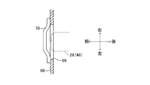
図1乃至図3、図5及び図6に示す樹脂製(例えば、ポリカーボネート製)の一体成形品であるメインカバー65は、略平板状の底板66と、底板66の左右両側部から上方に突設された一対の側壁67と、底板66の前縁部から前斜め上方に延び且つ自身の左右両端部が左右の側壁67の前端部にそれぞれ接続された前壁68と、を備える。図2に示すように底板66の後端部には切欠き66aが形成されている。さらに図5に示すように、左右の側壁67には前後方向に延びる多数のスリット67aが形成されている(図1では図示略)。また、前壁68の左右両側部にはそれぞれ複数列に渡って左右方向に延びるスリット68aが形成されている(図5に一部のスリット68aのみ図示)。
The
図2、図5、図6及び図7に示すように前壁68の幅方向の中央部には正面視横長矩形の貫通孔69が形成されている。さらに前壁68の前面の貫通孔69の左右両側部には、左右方向に延びる2本のフィン70の左右両端部がそれぞれ固定されている。2本のフィン70は共に貫通孔69の直前に位置している。即ち、2本のフィン70の後面は貫通孔69の前端より前方に位置する。さらに、2本のフィン70は互いに上下方向に離間している。さらに図7に示すように、平面視において各フィン70の左右方向の中央部は左右両側部よりも前方に位置している。
As shown in FIGS. 2, 5, 6 and 7, a horizontally long rectangular through
図3に示すように、底板66の上面の左右両側部には係止爪71がそれぞれ設けられている。さらに図3及び図5に示すように、前壁68の内面(後面)には貫通孔69の左右両側にそれぞれ位置し且つ後方に向かって延びる一対の係止爪72が設けられている。
As shown in FIG. 3, locking
そして、図3、図5及び図6に示すように前端突部28及び前端突部48の前端部を貫通孔69の内部に位置させた状態で、メインカバー65の左右の係止爪71がベース部材22の対応する係止孔25にそれぞれ係合され且つ左右の係止爪72がサブベース部材26の対応する係止孔29aにそれぞれ前方から係合されている。このようにしてメインカバー65をベース部材22及びサブベース部材26に装着すると、図1及び図2に示すように、メインカバー65の底板66がステレオカメラ装置45の下方及びハウジング40の下方を覆い、左右の側壁67がステレオカメラ装置45の左右両側を覆い、さらに前壁68がステレオカメラ装置45の前方を覆う。
Then, as shown in FIGS. 3, 5 and 6, the left and right locking
さらに図1及び図2に示すように、底板66の切欠き66aには、樹脂製のサブカバー75が装着される。さらにサブカバー75には切欠き75a(図2参照)が形成されている。そして、切欠き66a及び切欠き75aによって形成された開口には、電子インナーミラー76を支持する支持アーム77が下方から挿入され、且つ、支持アーム77の上端部がステレオカメラ装置45に固定されている。
Further, as shown in FIGS. 1 and 2, a
以上説明した撮影装置20では、ロケーター望遠カメラ装置30(ロケーターカメラ33、望遠カメラ34)とステレオカメラ装置45(カメラ49、カメラ50)の前後方向位置が互いにずれているので、必然的にこれらを覆うカバー(メインカバー65及びサブカバー75)全体の前後方向長はある程度の長さになる。しかし、前壁68の貫通孔69の内部に前端突部28及び前端突部48の前端部を位置させているので、前端突部28及び前端突部48の前端部が前壁68の後面より後方に位置する場合(図12の例)と比べて、上記カバー(メインカバー65及びサブカバー75)全体の前後方向長が短くなる。そのため、車両の運転席に着座した運転者の視界がメインカバー65及びサブカバー75によって狭められてしまったり、乗員がメインカバー65及びサブカバー75によって圧迫感を感じたりするおそれは小さい。
In the photographing
さらにメインカバー65の前壁68には貫通孔69及びフィン70が設けられている。そのため、前壁68の直後に位置するステレオカメラ装置45(カメラ49、カメラ50)及びロケーター望遠カメラ装置30(ロケーターカメラ33、望遠カメラ34)が発生した熱を、この貫通孔69と2つのフィン70との間の隙間及び各スリット67a、68aを通してメインカバー65の外側に排熱できる。
Further, the
さらに、図2の一点鎖線Yは、通常の体格を有し且つ運転席に着座した運転者がフロントウインドシールド10を通して車両の前方を見ているときの当該運転者の視界の上限位置を示している。図2から明らかなように、貫通孔69及びフィン70が(底板66ではなく)前壁68に設けられているので、貫通孔69及びフィン70が運転者の視界に入るおそれは殆どない。
Further, the alternate long and short dash line Y in FIG. 2 indicates the upper limit position of the driver's field of vision when the driver having a normal physique and sitting in the driver's seat is looking ahead of the vehicle through the
以上、本発明を実施形態及び変形例に基づいて説明したが、本発明は上記実施形態に限定されるものではなく、本発明の目的を逸脱しない限りにおいて種々の変更が可能である。 Although the present invention has been described above based on the embodiments and modifications, the present invention is not limited to the above embodiments, and various modifications can be made without departing from the object of the present invention.
図8及び図9は本発明の第1変形例の撮影装置20Aを示している。撮影装置20Aの構成は、フィン70を具備しない点及び後述する凹部73(孔)が形成されている点を除いて撮影装置20と同一である。撮影装置20Aのメインカバー65の前壁68の上面には前壁68を前後方向に貫通する凹部73(孔)が形成されている。そして図9に示すように、前壁68の凹部73の内部に前端突部28及び前端突部48の前端部が位置している。従って、第1変形例の撮影装置20Aは上記実施形態の撮影装置20と同様の作用効果を発揮可能である。
8 and 9 show the photographing
図10及び図11は本発明の第2変形例の撮影装置20Bを示している。撮影装置20Bの構成は、フィン70を具備しない点及び後述する貫通孔74が形成されている点を除いて撮影装置20と同一である。撮影装置20Bのメインカバー65の前壁68には前壁68を前後方向に貫通する貫通孔74が形成されている。そして図11に示すように、前壁68の貫通孔74の内部に前端突部28及び前端突部48の前端部が位置している。従って、第2変形例の撮影装置20Bは上記実施形態の撮影装置20と同様の作用効果を発揮可能である。
10 and 11 show the photographing
撮影装置20、20A、20Bがセンサーとして2つ、3つ又は5つ以上のカメラを備えてもよい。例えば、撮影装置20、20A、20Bがカメラ49、50(ステレオカメラ)の代わりに設けられた一つの単眼カメラと、この単眼カメラの後方に位置するロケーターカメラ33及び望遠カメラ34と、を備えてもよい。
The photographing
車両用撮影装置が複数のセンサーを備える場合は、そのうちの少なくとも一つがレーザレーダであってもよい。 If the vehicle imaging device includes a plurality of sensors, at least one of them may be a laser radar.
前壁68の左右方向の中央部ではなく側部に貫通孔69、74又は凹部73を形成してもよい。
Through
10・・・フロントウインドシールド、20、20A、20B・・・車両用撮影装置、22・・・ベース部材、26・・・サブベース部材、28・・・前端突部、33・・・ロケーターカメラ(レンズ、撮像素子)、34・・・望遠カメラ(レンズ、撮像素子)、46・・・ケース、48・・・前端突部、49、50・・・カメラ(レンズ、撮像素子)、65・・・メインカバー、69・・・貫通孔、70・・・フィン、73・・・凹部、74・・・貫通孔。 10 ... Front windshield, 20, 20A, 20B ... Vehicle photography device, 22 ... Base member, 26 ... Sub base member, 28 ... Front end protrusion, 33 ... Locator camera (Lens, image pickup element), 34 ... Telescope camera (lens, image pickup element), 46 ... Case, 48 ... Front end protrusion, 49, 50 ... Camera (lens, image pickup element), 65. .. Main cover, 69 ... Through hole, 70 ... Fin, 73 ... Recess, 74 ... Through hole.
Claims (1)
前記センサーを支持する複数のケースと、
前記フロントウインドシールドの車内側面に固定された被固定部と前記フロントウインドシールドから離れた位置において前記車両の前方に延びる前端突部とを有する部材と、
前記センサー及び前記ケースの少なくとも下方を覆うカバーと、
を備え、
少なくとも一つの前記センサーの車両前後方向の位置が他の前記センサーとは異なり、
最も前方に位置する前記センサーである前方センサーを支持する前記ケースの前端部に、前方に向かって突出する前端突部が設けられ、
前記ケースの前端突部が前記部材の前端突部に固定され、
前記カバーが、全ての前記センサーより前方に位置し且つ孔が設けられた前壁を有し、
前記ケースの前端突部の前端と、前記部材の前端突部の前端と、が前記カバーの前記前壁の孔に配設されている、
車両用撮影装置。 Multiple sensors located behind the front windshield on the vehicle,
Multiple cases supporting the sensor and
A member having a fixed portion fixed to the inner side surface of the front windshield and a front end protrusion extending to the front of the vehicle at a position away from the front windshield.
A cover that covers at least the bottom of the sensor and the case,
Equipped with
The position of at least one of the sensors in the vehicle front-rear direction is different from that of the other sensors.
A front end protrusion that protrudes forward is provided at the front end of the case that supports the front sensor, which is the sensor located at the frontmost position.
The front end protrusion of the case is fixed to the front end protrusion of the member,
The cover has a front wall located anterior to all the sensors and provided with holes .
The front end of the front end protrusion of the case and the front end of the front end protrusion of the member are arranged in the holes in the front wall of the cover.
Vehicle photography equipment.
Priority Applications (1)
| Application Number | Priority Date | Filing Date | Title |
|---|---|---|---|
| JP2018205633A JP7067422B2 (en) | 2018-10-31 | 2018-10-31 | Vehicle photography equipment |
Applications Claiming Priority (1)
| Application Number | Priority Date | Filing Date | Title |
|---|---|---|---|
| JP2018205633A JP7067422B2 (en) | 2018-10-31 | 2018-10-31 | Vehicle photography equipment |
Publications (2)
| Publication Number | Publication Date |
|---|---|
| JP2020069928A JP2020069928A (en) | 2020-05-07 |
| JP7067422B2 true JP7067422B2 (en) | 2022-05-16 |
Family
ID=70549129
Family Applications (1)
| Application Number | Title | Priority Date | Filing Date |
|---|---|---|---|
| JP2018205633A Active JP7067422B2 (en) | 2018-10-31 | 2018-10-31 | Vehicle photography equipment |
Country Status (1)
| Country | Link |
|---|---|
| JP (1) | JP7067422B2 (en) |
Cited By (1)
| Publication number | Priority date | Publication date | Assignee | Title |
|---|---|---|---|---|
| KR101419889B1 (en) * | 2012-11-05 | 2014-07-15 | 정휘동 | Apparatus of extracting beverage from capsule containing raw material for beverage |
Families Citing this family (1)
| Publication number | Priority date | Publication date | Assignee | Title |
|---|---|---|---|---|
| JP7345000B2 (en) * | 2022-02-04 | 2023-09-14 | 本田技研工業株式会社 | Retention devices and vehicles |
Citations (4)
| Publication number | Priority date | Publication date | Assignee | Title |
|---|---|---|---|---|
| JP2017030663A (en) | 2015-08-05 | 2017-02-09 | スズキ株式会社 | On-vehicle device mounting structure |
| US20170154241A1 (en) | 2015-12-01 | 2017-06-01 | Mobileye Vision Technologies Ltd. | Detecting visual information corresponding to an animal |
| JP2017523088A (en) | 2014-08-12 | 2017-08-17 | ダイムラー・アクチェンゲゼルシャフトDaimler AG | Support device for fixing to automobile window glass and automobile |
| JP2018043562A (en) | 2016-09-13 | 2018-03-22 | トヨタ自動車株式会社 | In-vehicle optical sensor device |
-
2018
- 2018-10-31 JP JP2018205633A patent/JP7067422B2/en active Active
Patent Citations (4)
| Publication number | Priority date | Publication date | Assignee | Title |
|---|---|---|---|---|
| JP2017523088A (en) | 2014-08-12 | 2017-08-17 | ダイムラー・アクチェンゲゼルシャフトDaimler AG | Support device for fixing to automobile window glass and automobile |
| JP2017030663A (en) | 2015-08-05 | 2017-02-09 | スズキ株式会社 | On-vehicle device mounting structure |
| US20170154241A1 (en) | 2015-12-01 | 2017-06-01 | Mobileye Vision Technologies Ltd. | Detecting visual information corresponding to an animal |
| JP2018043562A (en) | 2016-09-13 | 2018-03-22 | トヨタ自動車株式会社 | In-vehicle optical sensor device |
Cited By (1)
| Publication number | Priority date | Publication date | Assignee | Title |
|---|---|---|---|---|
| KR101419889B1 (en) * | 2012-11-05 | 2014-07-15 | 정휘동 | Apparatus of extracting beverage from capsule containing raw material for beverage |
Also Published As
| Publication number | Publication date |
|---|---|
| JP2020069928A (en) | 2020-05-07 |
Similar Documents
| Publication | Publication Date | Title |
|---|---|---|
| JP6962161B2 (en) | Sensor mounting structure | |
| KR101724299B1 (en) | Triple camera | |
| JP7172682B2 (en) | Camera mounting structure | |
| JP6922706B2 (en) | Sensor mounting structure | |
| US20160227078A1 (en) | Stereo Camera | |
| JP6885315B2 (en) | Sensor mounting structure | |
| JP2017092736A (en) | On-vehicle imaging apparatus | |
| EP3495211B1 (en) | Sensor mount structure | |
| JP5983693B2 (en) | Mirror device with display function and display switching method | |
| JP6601273B2 (en) | Camera device | |
| JP7025234B2 (en) | Out-of-vehicle monitoring device | |
| JP7067422B2 (en) | Vehicle photography equipment | |
| JP2016055782A5 (en) | ||
| JP6481970B2 (en) | Driver shooting device | |
| CN108696678B (en) | Camera module | |
| EP3508406B1 (en) | Saddle-type vehicle | |
| US20190158710A1 (en) | Occupant monitoring device | |
| JP2018196012A (en) | On-vehicle camera | |
| US10742857B2 (en) | Occupant monitoring apparatus | |
| JP2023114295A (en) | Holding device and vehicle | |
| JP7369677B2 (en) | Heating device for imaging equipment | |
| JP6229769B2 (en) | Mirror device with display function and display switching method | |
| JP2021187369A (en) | On-vehicle camera device | |
| US12043185B2 (en) | Camera holding structure | |
| WO2020003904A1 (en) | Stereo camera device |
Legal Events
| Date | Code | Title | Description |
|---|---|---|---|
| A621 | Written request for application examination |
Free format text: JAPANESE INTERMEDIATE CODE: A621 Effective date: 20210222 |
|
| A131 | Notification of reasons for refusal |
Free format text: JAPANESE INTERMEDIATE CODE: A131 Effective date: 20220126 |
|
| A977 | Report on retrieval |
Free format text: JAPANESE INTERMEDIATE CODE: A971007 Effective date: 20220127 |
|
| A521 | Request for written amendment filed |
Free format text: JAPANESE INTERMEDIATE CODE: A523 Effective date: 20220314 |
|
| TRDD | Decision of grant or rejection written | ||
| A01 | Written decision to grant a patent or to grant a registration (utility model) |
Free format text: JAPANESE INTERMEDIATE CODE: A01 Effective date: 20220329 |
|
| A61 | First payment of annual fees (during grant procedure) |
Free format text: JAPANESE INTERMEDIATE CODE: A61 Effective date: 20220411 |
|
| R151 | Written notification of patent or utility model registration |
Ref document number: 7067422 Country of ref document: JP Free format text: JAPANESE INTERMEDIATE CODE: R151 |