JP7052730B2 - Glass plate with dielectric multilayer film and its manufacturing method - Google Patents
Glass plate with dielectric multilayer film and its manufacturing method Download PDFInfo
- Publication number
- JP7052730B2 JP7052730B2 JP2018556665A JP2018556665A JP7052730B2 JP 7052730 B2 JP7052730 B2 JP 7052730B2 JP 2018556665 A JP2018556665 A JP 2018556665A JP 2018556665 A JP2018556665 A JP 2018556665A JP 7052730 B2 JP7052730 B2 JP 7052730B2
- Authority
- JP
- Japan
- Prior art keywords
- glass plate
- multilayer film
- dielectric multilayer
- covering portion
- surface covering
- Prior art date
- Legal status (The legal status is an assumption and is not a legal conclusion. Google has not performed a legal analysis and makes no representation as to the accuracy of the status listed.)
- Active
Links
Images


Classifications
-
- G—PHYSICS
- G02—OPTICS
- G02B—OPTICAL ELEMENTS, SYSTEMS OR APPARATUS
- G02B5/00—Optical elements other than lenses
- G02B5/20—Filters
- G02B5/28—Interference filters
-
- G—PHYSICS
- G02—OPTICS
- G02B—OPTICAL ELEMENTS, SYSTEMS OR APPARATUS
- G02B5/00—Optical elements other than lenses
- G02B5/20—Filters
- G02B5/28—Interference filters
- G02B5/281—Interference filters designed for the infrared light
- G02B5/282—Interference filters designed for the infrared light reflecting for infrared and transparent for visible light, e.g. heat reflectors, laser protection
-
- B—PERFORMING OPERATIONS; TRANSPORTING
- B32—LAYERED PRODUCTS
- B32B—LAYERED PRODUCTS, i.e. PRODUCTS BUILT-UP OF STRATA OF FLAT OR NON-FLAT, e.g. CELLULAR OR HONEYCOMB, FORM
- B32B7/00—Layered products characterised by the relation between layers; Layered products characterised by the relative orientation of features between layers, or by the relative values of a measurable parameter between layers, i.e. products comprising layers having different physical, chemical or physicochemical properties; Layered products characterised by the interconnection of layers
- B32B7/02—Physical, chemical or physicochemical properties
- B32B7/025—Electric or magnetic properties
-
- C—CHEMISTRY; METALLURGY
- C03—GLASS; MINERAL OR SLAG WOOL
- C03C—CHEMICAL COMPOSITION OF GLASSES, GLAZES OR VITREOUS ENAMELS; SURFACE TREATMENT OF GLASS; SURFACE TREATMENT OF FIBRES OR FILAMENTS MADE FROM GLASS, MINERALS OR SLAGS; JOINING GLASS TO GLASS OR OTHER MATERIALS
- C03C17/00—Surface treatment of glass, not in the form of fibres or filaments, by coating
- C03C17/34—Surface treatment of glass, not in the form of fibres or filaments, by coating with at least two coatings having different compositions
-
- G—PHYSICS
- G02—OPTICS
- G02B—OPTICAL ELEMENTS, SYSTEMS OR APPARATUS
- G02B5/00—Optical elements other than lenses
- G02B5/20—Filters
- G02B5/26—Reflecting filters
-
- G—PHYSICS
- G02—OPTICS
- G02B—OPTICAL ELEMENTS, SYSTEMS OR APPARATUS
- G02B5/00—Optical elements other than lenses
- G02B5/20—Filters
- G02B5/28—Interference filters
- G02B5/285—Interference filters comprising deposited thin solid films
-
- B—PERFORMING OPERATIONS; TRANSPORTING
- B32—LAYERED PRODUCTS
- B32B—LAYERED PRODUCTS, i.e. PRODUCTS BUILT-UP OF STRATA OF FLAT OR NON-FLAT, e.g. CELLULAR OR HONEYCOMB, FORM
- B32B17/00—Layered products essentially comprising sheet glass, or glass, slag, or like fibres
- B32B17/06—Layered products essentially comprising sheet glass, or glass, slag, or like fibres comprising glass as the main or only constituent of a layer, next to another layer of a specific material
- B32B17/10—Layered products essentially comprising sheet glass, or glass, slag, or like fibres comprising glass as the main or only constituent of a layer, next to another layer of a specific material of synthetic resin
- B32B17/10005—Layered products essentially comprising sheet glass, or glass, slag, or like fibres comprising glass as the main or only constituent of a layer, next to another layer of a specific material of synthetic resin laminated safety glass or glazing
- B32B17/10009—Layered products essentially comprising sheet glass, or glass, slag, or like fibres comprising glass as the main or only constituent of a layer, next to another layer of a specific material of synthetic resin laminated safety glass or glazing characterized by the number, the constitution or treatment of glass sheets
- B32B17/10036—Layered products essentially comprising sheet glass, or glass, slag, or like fibres comprising glass as the main or only constituent of a layer, next to another layer of a specific material of synthetic resin laminated safety glass or glazing characterized by the number, the constitution or treatment of glass sheets comprising two outer glass sheets
Landscapes
- Physics & Mathematics (AREA)
- General Physics & Mathematics (AREA)
- Optics & Photonics (AREA)
- Chemical & Material Sciences (AREA)
- Chemical Kinetics & Catalysis (AREA)
- Engineering & Computer Science (AREA)
- Life Sciences & Earth Sciences (AREA)
- General Chemical & Material Sciences (AREA)
- Geochemistry & Mineralogy (AREA)
- Materials Engineering (AREA)
- Organic Chemistry (AREA)
- Surface Treatment Of Glass (AREA)
- Surface Treatment Of Optical Elements (AREA)
- Laminated Bodies (AREA)
- Joining Of Glass To Other Materials (AREA)
Description
本発明は、誘電体多層膜付きガラス板及びその製造方法に関する。 The present invention relates to a glass plate with a dielectric multilayer film and a method for manufacturing the same.
誘電体多層膜付きガラス板における誘電体多層膜は、高屈折率膜と、高屈折率膜よりも屈折率が低い低屈折率膜とを交互に積層した構造を有し、例えば、反射を抑制する機能をガラス板に付与する。特許文献1の誘電体多層膜付きガラス板は、主面と側面との間の稜面を有し、誘電体多層膜付きガラス板の稜面の一部は、誘電体多層膜によって形成されている。 The dielectric multilayer film in the glass plate with a dielectric multilayer film has a structure in which a high refractive index film and a low refractive index film having a lower refractive index than the high refractive index film are alternately laminated, and for example, reflection is suppressed. The function to do is given to the glass plate. The glass plate with a dielectric multilayer film of Patent Document 1 has a ridge surface between a main surface and a side surface, and a part of the ridge surface of the glass plate with a dielectric multilayer film is formed by the dielectric multilayer film. There is.
上記特許文献1の誘電体多層膜付きガラス板において、ガラス板自体の端部は、ガラスが露出したエッチング面により形成されている。ここで、誘電体多層膜付きガラス板を、例えばモニター用のカバー部材として用いる場合、ガラス板の端部における稜面の少なくとも一部が露出した状態となるようにケースやフレームに組み付けられる場合がある。このように、誘電体多層膜付きガラス板をガラス板の稜面が露出した状態で使用する場合、その稜面では、誘電体多層膜の機能が発揮されず、誘電体多層膜付きガラス板としての機能性が不十分となるおそれがあった。 In the glass plate with a dielectric multilayer film of Patent Document 1, the end portion of the glass plate itself is formed by an etched surface on which the glass is exposed. Here, when a glass plate with a dielectric multilayer film is used as a cover member for a monitor, for example, it may be assembled to a case or a frame so that at least a part of the ridge surface at the end of the glass plate is exposed. be. As described above, when the glass plate with the dielectric multilayer film is used in a state where the ridge surface of the glass plate is exposed, the function of the dielectric multilayer film is not exhibited on the ridge surface, and the glass plate with the dielectric multilayer film is used. There was a risk that the functionality of the glass would be insufficient.
本発明は、こうした実情に鑑みてなされたものであり、その目的は、稜面を有するガラス板を用いた場合に誘電体多層膜の機能を好適に発揮させることのできる誘電体多層膜付きガラス板及びその製造方法を提供することにある。 The present invention has been made in view of such circumstances, and an object thereof is a glass with a dielectric multilayer film capable of suitably exerting the function of the dielectric multilayer film when a glass plate having a ridge surface is used. The present invention is to provide a plate and a method for manufacturing the plate.
上記課題を解決する誘電体多層膜付きガラス板は、ガラス板と、誘電体多層膜とを備える誘電体多層膜付きガラス板であって、前記ガラス板は、少なくとも一方の主面と側面との間の稜面を有し、前記誘電体多層膜は、前記ガラス板の前記主面を被覆する主面被覆部と、前記ガラス板の前記稜面を被覆する稜面被覆部と、を有する。 The glass plate with a dielectric multilayer film that solves the above problems is a glass plate with a dielectric multilayer film including a glass plate and a dielectric multilayer film, and the glass plate has at least one main surface and a side surface. The dielectric multilayer film has a ridge surface between them, and has a main surface covering portion that covers the main surface of the glass plate and a ridge surface covering portion that covers the ridge surface of the glass plate.
上記誘電体多層膜付きガラス板において、前記主面被覆部の反射率は、波長400nm以上、780nm以下の可視光領域の平均反射率において2.0%以下であり、前記稜面被覆部の反射率は、前記主面被覆部における前記可視光領域の平均反射率を100としたとき、前記可視光領域の平均反射率において1500以下であることが好ましい。 In the glass plate with a dielectric multilayer film, the reflectance of the main surface covering portion is 2.0% or less in the average reflectance in the visible light region having a wavelength of 400 nm or more and 780 nm or less, and the reflection of the ridge surface covering portion. The rate is preferably 1500 or less in the average reflectance of the visible light region when the average reflectance of the visible light region in the main surface covering portion is 100.
上記誘電体多層膜付きガラス板において、前記主面被覆部の反射率は、波長950nm以上、1100nm以下の赤外光領域の平均反射率において70%以上であることが好ましい。 In the glass plate with a dielectric multilayer film, the reflectance of the main surface covering portion is preferably 70% or more in the average reflectance in the infrared light region having a wavelength of 950 nm or more and 1100 nm or less.
上記誘電体多層膜付きガラス板において、前記誘電体多層膜の前記主面被覆部と前記稜面被覆部とは、連続した同種類の複数層から構成され、前記稜面被覆部の厚さは、前記主面被覆部の厚さを100としたとき、50以上、95以下であることが好ましい。 In the glass plate with a dielectric multilayer film, the main surface covering portion and the ridge surface covering portion of the dielectric multilayer film are composed of a plurality of continuous layers of the same type, and the thickness of the ridge surface covering portion is When the thickness of the main surface covering portion is 100, it is preferably 50 or more and 95 or less.
上記誘電体多層膜付きガラス板において、前記稜面被覆部の少なくとも一部が露出した状態で取り付けられるカバー部材として用いられることが好ましい。
上記誘電体多層膜付きガラス板の製造方法は、ガラス板材に前記稜面を形成して前記ガラス板を得る工程と、前記ガラス板の前記主面及び前記ガラス板の前記稜面に前記誘電体多層膜を設ける工程と、を備えることが好ましい。In the glass plate with a dielectric multilayer film, it is preferable to use it as a cover member to be attached in a state where at least a part of the ridge surface covering portion is exposed.
The method for manufacturing a glass plate with a dielectric multilayer film includes a step of forming the ridge surface on a glass plate material to obtain the glass plate, and the dielectric material on the main surface of the glass plate and the ridge surface of the glass plate. It is preferable to include a step of providing a multilayer film.
本発明によれば、稜面を有するガラス板を用いた場合に誘電体多層膜の機能を好適に発揮させることができる。 According to the present invention, the function of the dielectric multilayer film can be suitably exhibited when a glass plate having a ridge surface is used.
以下、誘電体多層膜付きガラス板及びその製造方法の実施形態について図面を参照して説明する。なお、図面では、説明の便宜上、構成の一部を誇張して示す場合がある。また、各部分の寸法比率についても、実際と異なる場合がある。 Hereinafter, embodiments of a glass plate with a dielectric multilayer film and a method for manufacturing the same will be described with reference to the drawings. In the drawings, a part of the configuration may be exaggerated for convenience of explanation. In addition, the dimensional ratio of each part may differ from the actual one.
図1及び図2に示すように、誘電体多層膜付きガラス板11は、ガラス板12と誘電体多層膜13とを備えている。ガラス板12は、一方の主面12aと、側面12bとの間の稜面12cを有している。つまり稜面12cは、主面12aと側面12bとを接続している。ガラス板12の稜面12cの傾斜角度は、主面12aに対する面取り角度θにおいて、20°以上、70°以下の範囲に形成されていることが好ましい。本実施形態のガラス板12の稜面12cの傾斜角度は、主面12aに対する面取り角度θにおいて、45°に形成されている。ガラス板12を構成するガラスとしては、例えば、ケイ酸塩系ガラス、ホウ酸塩系ガラス、ホウケイ酸塩系ガラス、リン酸塩系ガラス、及びホウリン酸塩系ガラスが挙げられる。ガラス板12の厚さは、例えば、0.1~5mmの範囲である。
As shown in FIGS. 1 and 2, the
誘電体多層膜13の機能としては、例えば、可視光の反射を抑制する機能、及び赤外光の反射を促進する機能が挙げられる。誘電体多層膜13は、ガラス板12の主面12aを被覆する主面被覆部13aと、ガラス板12の稜面12cを被覆する稜面被覆部13bとを有している。誘電体多層膜13は、高屈折率膜Hと、高屈折率膜Hよりも屈折率が低い低屈折率膜Lとを交互に積層した構造を有する。高屈折率膜Hとしては、例えば、酸化ニオブ、酸化チタン、酸化タンタル、酸化ランタン、酸化タングステン、及び酸化ジルコニウムから選ばれる少なくとも一種が挙げられる。高屈折率膜Hは、酸化ニオブを含むことが好ましい。低屈折率膜Lとしては、例えば、酸化ケイ素、及び酸化アルミニウムから選ばれる少なくとも一種が挙げられる。低屈折率膜Lは、酸化ケイ素を含むことが好ましい。
Functions of the
誘電体多層膜13において、高屈折率膜Hと低屈折率膜Lとの合計積層数は、例えば、4層以上、60層以下である。なお、誘電体多層膜13では、高屈折率膜Hから低屈折率膜Lに向けて屈折率が漸減または漸増する漸移層を高屈折率膜Hと低屈折率膜Lとの間に設けてもよい。また、誘電体多層膜13からガラス板12に向けて屈折率が漸減または漸増する漸移層をガラス板12と誘電体多層膜13との間に設けてもよい。また、高屈折率膜Hと低屈折率膜L以外にも、屈折率が高屈折率膜Hよりも小さく、かつ、低屈折率膜Lより大きい中屈折率膜を設けてもよい。
In the
本実施形態の誘電体多層膜13の主面被覆部13aと稜面被覆部13bとは、連続した同種類の複数層から構成されている。稜面被覆部13bの厚さT1は、稜面被覆部13bの剥離を抑制するという観点から、主面被覆部13aの厚さT2を100としたとき、95以下であることが好ましく、より好ましくは85以下である。稜面被覆部13bの厚さT1は、主面被覆部13aと稜面被覆部13bとの光学特性を近づけるという観点から、主面被覆部13aの厚さT2を100としたとき、50以上であることが好ましく、より好ましくは60以上であり、さらに好ましくは65以上である。
The main surface covering portion 13a and the ridge
誘電体多層膜13の主面被覆部13aの反射率は、波長400nm以上、780nm以下の可視光領域の平均反射率において2.0%以下であることが好ましい。
誘電体多層膜13の稜面被覆部13bの反射率は、稜面被覆部13bにおいて可視光の反射を抑制するという観点から、主面被覆部13aにおける上記可視光領域の平均反射率を100としたとき、上記可視光領域の平均反射率において1500以下であることが好ましく、より好ましくは1000以下である。The reflectance of the main surface covering portion 13a of the
As for the reflectance of the ridge
誘電体多層膜13の主面被覆部13aの反射率は、主面被覆部13aにおいて赤外光の反射を促進するという観点から、波長950nm以上、1100nm以下の赤外光領域の平均反射率において70%以上であることが好ましい。これにより、赤外光が透過することによる悪影響(例えば、熱による影響)を抑制することができる。
The reflectance of the main surface covering portion 13a of the
誘電体多層膜13の稜面被覆部13bの反射率は、稜面被覆部13bにおいて赤外光の反射を促進するという観点から、主面被覆部13aにおける上記赤外光領域の平均反射率を100としたとき、上記赤外光領域の平均反射率において70以上であることが好ましい。
The reflectance of the ridge
上記の平均反射率は、次のように求めることができる。誘電体多層膜付きガラス板11の反射率の測定面とは反対側の面(裏面)をサンドブラストによりブラスト処理した後、ブラスト処理した面を黒塗り加工して裏面の反射を無くした状態とした。このように加工した誘電体多層膜付きガラス板11の所定の波長範囲における分光反射率(入射角5°)を、分光光度計(例えば、U4100、株式会社日立製作所製)により測定(測定波長間隔1nm)し、各波長の反射率の平均値を計算することにより平均反射率を求められる。また、稜面被覆部13bの反射率は、入射角を、(面取り角度θ-5)°、すなわち面取り角度θから5°を減じた値として測定した値である。
The above average reflectance can be obtained as follows. After blasting the surface (back surface) of the
次に、誘電体多層膜付きガラス板11の製造方法について説明する。
誘電体多層膜付きガラス板11の製造方法は、ガラス板材に稜面12cを形成してガラス板12を得る工程と、ガラス板12の主面12a及びガラス板12の稜面12cに誘電体多層膜13を設ける工程とを備えている。ガラス板12を得る工程で準備するガラス板材は、マザーガラスを所定の寸法に割断することで得られる。ガラス板12を得る工程において、ガラス板12の稜面12cは、ガラス板材の端面を研磨することで形成することができる。Next, a method for manufacturing the
The method for manufacturing the
誘電体多層膜付きガラス板11の製造方法において、誘電体多層膜13を設ける工程では、周知の成膜方法を用いてガラス板12の主面12a及びガラス板12の稜面12cに誘電体多層膜13の各層を順次形成する。誘電体多層膜13の成膜方法としては、例えば、スパッタリング法、真空蒸着法、イオンビーム法、イオンプレーティング法、及びCVD法が挙げられる。これらの成膜方法の中でも、各層の厚さを高精度で制御することができるとともに、安定した膜質の誘電体多層膜13が得られることから、スパッタリング法が好ましい。
In the process of manufacturing the
主面被覆部13aの厚さT2に対して稜面被覆部13bの厚さT1を変更する方法としては、スパッタリング法において、例えば、防膜板(防着板、シールド等と呼ばれる場合もある。)を用いる方法が挙げられる。詳述すると、ガラス板12の周縁に沿った枠状の防膜板と、ガラス板12の主面12aとの相対的な高さ位置を調整することで稜面被覆部13bの厚さT1を変更することができる。すなわち、ガラス板12の主面12aに対して防膜板の高さ位置を低くするにつれて稜面被覆部13bの厚さT1はより厚くなる。より具体的には、ガラス板12の主面12aよりも防膜板の主面の高さ位置を低くすることで、稜面被覆部13bの厚さT1を、主面被覆部13aの厚さT2を100としたとき、50以上とすることができる。
As a method of changing the thickness T1 of the ridge
次に、誘電体多層膜付きガラス板11の用途について説明する。
誘電体多層膜付きガラス板11は、稜面被覆部13bの少なくとも一部が露出した状態で取り付けられるカバー部材として好適に用いられる。詳述すると、誘電体多層膜付きガラス板11は、その端部を図1に二点鎖線で示すように支持部材Sで支持することで、カバー部材として用いることができる。誘電体多層膜付きガラス板11(カバー部材)は、ガラス板12の主面12a側(誘電体多層膜13側)が外側となるように配置され、図示を省略した筐体内の部品(例えば、電子部品)を保護する。カバー部材としては、例えば、モニター用途やディスプレイ用途が挙げられる。Next, the use of the
The
次に、誘電体多層膜付きガラス板11の試験例を説明する。
(試験例1)
ガラス板12(ソーダガラス板、厚さ2.5mm、稜面12cの面取り角度θ=45°)の上に誘電体多層膜13をスパッタリング法で形成した。スパッタリング法による誘電体多層膜13の形成には、ロードロック式スパッタリング装置を用いた。誘電体多層膜13の形成では、成膜材料の粒子がガラス板12の稜面12cよりもガラス板12の主面12aに優先して堆積するようにスパッタリングを行った。これにより、主面被覆部13aの厚さT2を100としたとき、稜面被覆部13bの厚さT1が70、80、及び90となる誘電体多層膜付きガラス板11を得た。試験例1の誘電体多層膜付きガラス板11の主面被覆部13aにおける誘電体多層膜13の各層の厚さを表1に示す。誘電体多層膜13は、ガラス板12に近い側を第1層として積層された合計7層の積層構造であり、第1層はガラス板12と第2層との接着性を高めるアンカー層として設けられている。Next, a test example of the
(Test Example 1)
A

図3に示すように、稜面被覆部13bの反射率は、稜面被覆部13bの厚さT1が70の誘電体多層膜付きガラス板11については、波長550nm付近から上昇する。稜面被覆部13bの反射率は、稜面被覆部13bの厚さT1が80の誘電体多層膜付きガラス板11については、波長630nm付近から上昇する。稜面被覆部13bの反射率は、稜面被覆部13bの厚さT1が90の誘電体多層膜付きガラス板11については、波長700nm付近から上昇する。これは、稜面被覆部13bの厚さT1が小さくなるにつれて、主面被覆部13aの反射率の極大値(ピーク)が短波長側にシフトしていることを示している。
As shown in FIG. 3, the reflectance of the ridge
ここで、誘電体多層膜13の厚さを厚くすることで、可視光領域における長波長側の反射を少なくすることができる。すなわち、可視光の反射率の上昇開始波長をより長波長側とするには、例えば、誘電体多層膜13の厚さをより厚く設定すればよい。また、赤外光領域における反射を多くしたい場合、例えば、誘電体多層膜13の厚さをより厚く設定すればよい。
Here, by increasing the thickness of the
上記のように7層構造の誘電体多層膜13において、可視光の反射を抑制し、赤外光の反射を促進するためには、誘電体多層膜13の厚さは、例えば、760nm以上、880nm以下の範囲に設定される。
In the
試験例1の誘電体多層膜付きガラス板11において、主面被覆部13aでの可視光領域の平均反射率は1.17%、稜面被覆部13bでの可視光領域の平均反射率は、主面被覆部13aの厚さT2を100としたときの稜面被覆部13bの厚さT1が70の場合、32.03%、厚さT1が80の場合、15.11%、厚さT1が90の場合、3.45%であった。
In the
試験例1の誘電体多層膜付きガラス板11において、主面被覆部13aでの赤外光領域の平均反射率は、72.10%、稜面被覆部13bでの赤外光領域の平均反射率は、厚さT1が70の場合、20.24%、厚さT1が80の場合、58.27%、厚さT1が90の場合、73.12%であった。
In the
(試験例2)
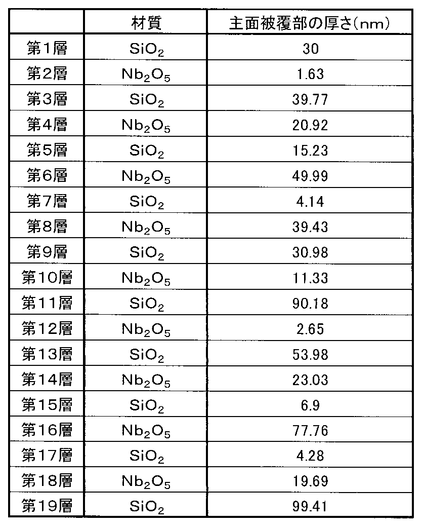
試験例2では、誘電体多層膜13の構成を変更した以外は、試験例1と同様に誘電体多層膜付きガラス板11を得た。なお、試験例2では、主面被覆部13aの厚さT2を100としたとき、稜面被覆部13bの厚さT1が60、65、70、80、及び90となる5種類の誘電体多層膜付きガラス板11を得た。試験例2の誘電体多層膜付きガラス板11の主面被覆部13aにおける誘電体多層膜13の各層の厚さを表2に示す。試験例2の誘電体多層膜13は、ガラス板12に近い側を第1層として積層された合計19層の積層構造であり、第1層はガラス板12と第2層との接着性を高めるアンカー層として設けられている。(Test Example 2)
In Test Example 2, a
試験例2の誘電体多層膜付きガラス板11において、主面被覆部13aでの波長950~1100nmの赤外光領域の平均反射率は、0.77%、稜面被覆部13bでの赤外光領域の平均反射率は、厚さT1が60の場合、36.86%、厚さT1が65の場合、35.06%、厚さT1が70の場合、29.65%、厚さT1が80の場合、13.01%、厚さT1が90の場合、2.18%であった。
In the
図4は、試験例2の誘電体多層膜付きガラス板11に照射した光の波長と反射率との関係を示すグラフである。図4に示すように、稜面被覆部13bの厚さT1が60であっても、稜面被覆部13bでの可視光領域の平均反射率を低く抑えることができる。
FIG. 4 is a graph showing the relationship between the wavelength and the reflectance of the light irradiated to the
以上詳述した実施形態によれば、次のような作用効果が発揮される。
(1)誘電体多層膜付きガラス板11におけるガラス板12は、少なくとも一方の主面12aと側面12bとの間の稜面12cを有している。誘電体多層膜付きガラス板11における誘電体多層膜13は、ガラス板12の主面12aを被覆する主面被覆部13aと、ガラス板12の稜面12cを被覆する稜面被覆部13bとを有している。この構成によれば、ガラス板12の稜面12c上においても、誘電体多層膜13の稜面被覆部13bによって誘電体多層膜13の機能が発揮される。従って、稜面12cを有するガラス板12を用いた場合に誘電体多層膜13の機能を好適に発揮させることができる。これにより、例えば、稜面12cを有するガラス板12のデザイン性と誘電体多層膜13の機能性との少なくともいずれかを発揮させることができる。According to the embodiment described in detail above, the following effects are exhibited.
(1) The
(2)誘電体多層膜付きガラス板11において、誘電体多層膜13の主面被覆部13aの反射率は、波長400nm以上、780nm以下の可視光領域の平均反射率において2.0%以下であることが好ましい。誘電体多層膜13の稜面被覆部13bの反射率は、主面被覆部13aにおける上記可視光領域の平均反射率を100としたとき、上記可視光領域の平均反射率において1500以下であることが好ましい。
(2) In the
この場合、誘電体多層膜付きガラス板11において、誘電体多層膜13の主面被覆部13a及び稜面被覆部13bの可視光の反射を好適に抑制することができる。
また、誘電体多層膜付きガラス板11をモニター用のカバー部材として用いる場合、稜面被覆部13bにおける光の反射を要因として、稜面被覆部13bが主面被覆部13aとは異なる色に見え難くなる。主面被覆部13aの色と稜面被覆部13bの色との統一感が得られるため、デザインに優れるカバー部材を提供することができる。In this case, in the
Further, when the
(3)誘電体多層膜付きガラス板11において、誘電体多層膜13の主面被覆部13aの反射率は、波長950nm以上、1100nm以下の赤外光領域の平均反射率において70%以上であることが好ましい。
(3) In the
この場合、誘電体多層膜付きガラス板11において、誘電体多層膜13の主面被覆部13a及び稜面被覆部13bの赤外光の反射を好適に促進することができる。
また、誘電体多層膜付きガラス板11をモニター用のカバー部材として用いる場合、モニターが損傷する要因として熱による損傷が考えられる。赤外光の反射を促進することで、熱によるモニターの損傷を抑制できる。In this case, in the
Further, when the
(4)誘電体多層膜付きガラス板11において、誘電体多層膜13の主面被覆部13aと稜面被覆部13bとは、連続した同種類の複数層から構成され、誘電体多層膜13の稜面被覆部13bの厚さT1は、主面被覆部13aの厚さT2を100としたとき、50以上、95以下であることが好ましい。
(4) In the
ここで、誘電体多層膜13の主面被覆部13aの厚さT2よりも稜面被覆部13bの厚さT1を薄くすることで、ガラス板12の稜面12cから稜面被覆部13bが剥離することを抑制できるものの、主面被覆部13aと稜面被覆部13bとの光学特性が大きく異なるおそれがある。上記構成の場合、稜面被覆部13bの剥離を抑制し、かつ、稜面被覆部13bの光学特性を主面被覆部13aの光学特性に近づけることができる。これにより、例えば、可視光の反射抑制機能を有する誘電体多層膜13の場合、主面被覆部13aと稜面被覆部13bとの反射率を互いに近づけることができるため、主面被覆部13aと稜面被覆部13bとが異なる色調に視認されることを抑えることができる。
Here, by making the thickness T1 of the ridge
(5)誘電体多層膜付きガラス板11は、誘電体多層膜13の稜面被覆部13bの少なくとも一部が露出した状態で取り付けられるカバー部材として用いられることで、例えば、ガラス板12の稜面12c上であっても、誘電多層膜の機能を発揮する物品を提供することができる。
(5) The
(変更例)
上記実施形態を次のように変更して構成してもよい。
・誘電体多層膜付きガラス板11において、上記ガラス板12の主面12aと反対側の主面や、ガラス板12の側面12bに誘電体多層膜を設けてもよい。(Change example)
The above embodiment may be modified as follows.
In the
・誘電体多層膜付きガラス板11において、誘電体多層膜13の主面被覆部13aと稜面被覆部13bとは、連続した同種類の複数層から構成されているが、異なる種類の複数層から構成されていてもよく、主面被覆部13aの合計積層数と、稜面被覆部13bの合計積層数は、異なっていてもよい。但し、誘電体多層膜付きガラス板11の製造工程を簡素化するという観点から、上述したように連続した同種類の複数層から構成されることが好ましい。
In the
・誘電体多層膜付きガラス板11の誘電体多層膜13は、可視光の反射を抑制する機能と、赤外光の反射を促進する機能のいずれも有しているが、可視光の反射を抑制する機能、及び赤外光の反射を促進する機能の少なくとも一方の機能を有していてもよい。
The
・誘電体多層膜付きガラス板11の誘電体多層膜13は、少なくとも紫外線の反射を促進する機能を有していてもよい。また、誘電体多層膜付きガラス板11は、紫外線遮蔽膜をさらに備えていてもよい。紫外線遮蔽膜は、ガラス板12の主面12aと反対側の主面、ガラス板12と誘電体多層膜13との間、及び誘電体多層膜13上の少なくとも一箇所に設けることができる。
The
11…誘電体多層膜付きガラス板、12…ガラス板、12a…主面、12b…側面、12c…稜面、13…誘電体多層膜、13a…主面被覆部、13b…稜面被覆部、T1…厚さ(稜面被覆部)、T2…厚さ(主面被覆部)。 11 ... glass plate with dielectric multilayer film, 12 ... glass plate, 12a ... main surface, 12b ... side surface, 12c ... ridge surface, 13 ... dielectric multilayer film, 13a ... main surface covering portion, 13b ... ridge surface covering portion, T1 ... Thickness (ridge surface covering portion), T2 ... Thickness (main surface covering portion).
Claims (5)
前記ガラス板は、少なくとも一方の主面と側面との間の稜面を有し、
前記誘電体多層膜は、前記ガラス板の前記主面を被覆する主面被覆部と、前記ガラス板の前記稜面を被覆する稜面被覆部と、を有し、
前記誘電体多層膜の前記主面被覆部と前記稜面被覆部とは、連続した同種類の複数層から構成され、
前記稜面被覆部の厚さは、前記主面被覆部の厚さを100としたとき、50以上、95以下であることを特徴とする誘電体多層膜付きガラス板。 A glass plate with a dielectric multilayer film including a glass plate and a dielectric multilayer film.
The glass plate has a ridge between at least one main surface and a side surface.
The dielectric multilayer film has a main surface covering portion that covers the main surface of the glass plate and a ridge surface covering portion that covers the ridge surface of the glass plate .
The main surface covering portion and the ridge surface covering portion of the dielectric multilayer film are composed of a plurality of continuous layers of the same type.
The glass plate with a dielectric multilayer film is characterized in that the thickness of the ridge surface covering portion is 50 or more and 95 or less when the thickness of the main surface covering portion is 100 .
前記稜面被覆部の反射率は、前記主面被覆部における前記可視光領域の平均反射率を100としたとき、前記可視光領域の平均反射率において1500以下であることを特徴とする請求項1に記載の誘電体多層膜付きガラス板。 The reflectance of the main surface covering portion is 2.0% or less in the average reflectance in the visible light region having a wavelength of 400 nm or more and 780 nm or less.
The claim is characterized in that the reflectance of the ridge surface covering portion is 1500 or less in the average reflectance of the visible light region when the average reflectance of the visible light region in the main surface covering portion is 100. The glass plate with a dielectric multilayer film according to 1.
ガラス板材に前記稜面を形成して前記ガラス板を得る工程と、
前記ガラス板の前記主面及び前記ガラス板の前記稜面に前記誘電体多層膜を設ける工程と、を備えることを特徴とする誘電体多層膜付きガラス板の製造方法。 The method for manufacturing a glass plate with a dielectric multilayer film according to any one of claims 1 to 4 .
The process of forming the ridge surface on the glass plate material to obtain the glass plate, and
A method for manufacturing a glass plate with a dielectric multilayer film, comprising a step of providing the dielectric multilayer film on the main surface of the glass plate and the ridge surface of the glass plate.
Applications Claiming Priority (3)
| Application Number | Priority Date | Filing Date | Title |
|---|---|---|---|
| JP2016243109 | 2016-12-15 | ||
| JP2016243109 | 2016-12-15 | ||
| PCT/JP2017/044378 WO2018110499A1 (en) | 2016-12-15 | 2017-12-11 | Glass plate with dielectric multilayer film and manufacturing method thereof |
Publications (2)
| Publication Number | Publication Date |
|---|---|
| JPWO2018110499A1 JPWO2018110499A1 (en) | 2019-10-31 |
| JP7052730B2 true JP7052730B2 (en) | 2022-04-12 |
Family
ID=62558702
Family Applications (1)
| Application Number | Title | Priority Date | Filing Date |
|---|---|---|---|
| JP2018556665A Active JP7052730B2 (en) | 2016-12-15 | 2017-12-11 | Glass plate with dielectric multilayer film and its manufacturing method |
Country Status (5)
| Country | Link |
|---|---|
| US (1) | US11307336B2 (en) |
| JP (1) | JP7052730B2 (en) |
| CN (1) | CN110088057A (en) |
| TW (1) | TW201834995A (en) |
| WO (1) | WO2018110499A1 (en) |
Families Citing this family (10)
| Publication number | Priority date | Publication date | Assignee | Title |
|---|---|---|---|---|
| CN111880256B (en) | 2017-09-29 | 2022-03-08 | 耐克创新有限合伙公司 | Structurally colored articles and methods of making and using structurally colored articles |
| US11597996B2 (en) | 2019-06-26 | 2023-03-07 | Nike, Inc. | Structurally-colored articles and methods for making and using structurally-colored articles |
| US20210022444A1 (en) | 2019-07-26 | 2021-01-28 | Nike, Inc. | Structurally-colored articles and methods for making and using structurally-colored articles |
| US11986042B2 (en) | 2019-10-21 | 2024-05-21 | Nike, Inc. | Structurally-colored articles and methods for making and using structurally-colored articles |
| WO2021161879A1 (en) | 2020-02-13 | 2021-08-19 | Agc株式会社 | Glass plate structure and on-vehicle display device |
| EP4107007B1 (en) * | 2020-05-29 | 2023-08-30 | Nike Innovate C.V. | Structurally-colored articles and methods for making and using structurally-colored articles |
| US11241062B1 (en) | 2020-08-07 | 2022-02-08 | Nike, Inc. | Footwear article having repurposed material with structural-color concealing layer |
| US11889894B2 (en) | 2020-08-07 | 2024-02-06 | Nike, Inc. | Footwear article having concealing layer |
| US11129444B1 (en) | 2020-08-07 | 2021-09-28 | Nike, Inc. | Footwear article having repurposed material with concealing layer |
| JPWO2023238710A1 (en) * | 2022-06-10 | 2023-12-14 |
Citations (2)
| Publication number | Priority date | Publication date | Assignee | Title |
|---|---|---|---|---|
| JP2002362943A (en) | 2001-06-08 | 2002-12-18 | Asahi Techno Glass Corp | Substrate for optical device, optical device and method for manufacturing optical device |
| WO2014104009A1 (en) | 2012-12-27 | 2014-07-03 | Hoya株式会社 | Mask blank substrate processing device, mask blank substrate processing method, mask blank substrate fabrication method, mask blank fabrication method, and transfer mask fabrication method |
Family Cites Families (8)
| Publication number | Priority date | Publication date | Assignee | Title |
|---|---|---|---|---|
| JPS6051081B2 (en) * | 1978-01-20 | 1985-11-12 | キヤノン株式会社 | Aspheric anti-reflection coating |
| CN1319868A (en) * | 2000-01-26 | 2001-10-31 | 松下电器产业株式会社 | Surface discharge type display device with excellent power consumption suppression effect |
| JP4619166B2 (en) * | 2005-03-28 | 2011-01-26 | シチズンホールディングス株式会社 | Windshield glass for watches |
| JP5096425B2 (en) * | 2009-07-23 | 2012-12-12 | 日本電波工業株式会社 | Manufacturing method of optical filter |
| JP2013252992A (en) * | 2012-06-07 | 2013-12-19 | Nippon Electric Glass Co Ltd | Dielectric multilayer film, glass plate with dielectric multilayer film and method for producing glass plate with dielectric multilayer film |
| US10197716B2 (en) * | 2012-12-19 | 2019-02-05 | Viavi Solutions Inc. | Metal-dielectric optical filter, sensor device, and fabrication method |
| CN103407232A (en) * | 2013-08-14 | 2013-11-27 | 江苏奥蓝工程玻璃有限公司 | Offline antireflection coated glass and manufacturing method thereof |
| JP6225695B2 (en) | 2013-12-25 | 2017-11-08 | セイコーエプソン株式会社 | Cover glass and watch |
-
2017
- 2017-12-11 JP JP2018556665A patent/JP7052730B2/en active Active
- 2017-12-11 WO PCT/JP2017/044378 patent/WO2018110499A1/en not_active Ceased
- 2017-12-11 US US16/468,673 patent/US11307336B2/en active Active
- 2017-12-11 CN CN201780076530.6A patent/CN110088057A/en active Pending
- 2017-12-13 TW TW106143659A patent/TW201834995A/en unknown
Patent Citations (2)
| Publication number | Priority date | Publication date | Assignee | Title |
|---|---|---|---|---|
| JP2002362943A (en) | 2001-06-08 | 2002-12-18 | Asahi Techno Glass Corp | Substrate for optical device, optical device and method for manufacturing optical device |
| WO2014104009A1 (en) | 2012-12-27 | 2014-07-03 | Hoya株式会社 | Mask blank substrate processing device, mask blank substrate processing method, mask blank substrate fabrication method, mask blank fabrication method, and transfer mask fabrication method |
Also Published As
| Publication number | Publication date |
|---|---|
| JPWO2018110499A1 (en) | 2019-10-31 |
| WO2018110499A1 (en) | 2018-06-21 |
| CN110088057A (en) | 2019-08-02 |
| US20190346603A1 (en) | 2019-11-14 |
| US11307336B2 (en) | 2022-04-19 |
| TW201834995A (en) | 2018-10-01 |
Similar Documents
| Publication | Publication Date | Title |
|---|---|---|
| JP7052730B2 (en) | Glass plate with dielectric multilayer film and its manufacturing method | |
| JP5840448B2 (en) | Antireflection film and method of manufacturing antireflection film | |
| TWI659936B (en) | Scratch-resistant chemically tempered glass substrate and use thereof | |
| KR101141232B1 (en) | Conductive film with high transmittance having a number of anti reflection coating, touch panel using the same and manufacturing method thereof | |
| CN108521766A (en) | A transparent layered element containing the screen area | |
| EP3358404A1 (en) | Video projection structure and video projection method | |
| JP5244976B2 (en) | Plate member and structure with observation window | |
| JP4190773B2 (en) | Antireflection film, optical lens and optical lens unit | |
| JP2013156460A (en) | Cover member for portable information terminal | |
| US10816707B2 (en) | Gold color tone multilayer coat and reflector including the same | |
| JP2023027141A (en) | Anti-reflective film-attached transparent substrate and image display device | |
| JP2016218335A (en) | Glass member with optical multi-layer film | |
| CN210506093U (en) | Antireflection film and antireflection glass | |
| WO2015146016A1 (en) | Process for producing lens with antireflection function | |
| JP2017032852A (en) | Antireflection film and optical component | |
| KR102426399B1 (en) | Optical filter and lens system having the same | |
| KR20200143670A (en) | Lens coating layer | |
| CN100580485C (en) | Optical filter and method for manufacturing optical filter | |
| KR20170028190A (en) | Glass or Film Coating Layers of Vehicle Display and the Coating Method for It | |
| JP2000347002A (en) | Anti-reflective coating | |
| KR20240163664A (en) | Transparent body and image display device with anti-reflection film | |
| JP7563019B2 (en) | Coverslips | |
| JPS62143846A (en) | Antireflection treatment of transparent substrate | |
| TWM525452U (en) | Cover lens | |
| JP2019117311A (en) | Nd filter and manufacturing method therefor |
Legal Events
| Date | Code | Title | Description |
|---|---|---|---|
| A621 | Written request for application examination |
Free format text: JAPANESE INTERMEDIATE CODE: A621 Effective date: 20200918 |
|
| A131 | Notification of reasons for refusal |
Free format text: JAPANESE INTERMEDIATE CODE: A131 Effective date: 20211012 |
|
| A521 | Request for written amendment filed |
Free format text: JAPANESE INTERMEDIATE CODE: A523 Effective date: 20211201 |
|
| TRDD | Decision of grant or rejection written | ||
| A01 | Written decision to grant a patent or to grant a registration (utility model) |
Free format text: JAPANESE INTERMEDIATE CODE: A01 Effective date: 20220301 |
|
| A61 | First payment of annual fees (during grant procedure) |
Free format text: JAPANESE INTERMEDIATE CODE: A61 Effective date: 20220314 |
|
| R150 | Certificate of patent or registration of utility model |
Ref document number: 7052730 Country of ref document: JP Free format text: JAPANESE INTERMEDIATE CODE: R150 |