JP7051186B2 - Exhaust gas purification catalyst - Google Patents
Exhaust gas purification catalyst Download PDFInfo
- Publication number
- JP7051186B2 JP7051186B2 JP2018095584A JP2018095584A JP7051186B2 JP 7051186 B2 JP7051186 B2 JP 7051186B2 JP 2018095584 A JP2018095584 A JP 2018095584A JP 2018095584 A JP2018095584 A JP 2018095584A JP 7051186 B2 JP7051186 B2 JP 7051186B2
- Authority
- JP
- Japan
- Prior art keywords
- exhaust gas
- catalyst
- partition wall
- catalyst layer
- gas purification
- Prior art date
- Legal status (The legal status is an assumption and is not a legal conclusion. Google has not performed a legal analysis and makes no representation as to the accuracy of the status listed.)
- Active
Links
- 239000003054 catalyst Substances 0.000 title claims description 302
- 238000000746 purification Methods 0.000 title claims description 93
- 210000004027 cell Anatomy 0.000 claims description 104
- 238000005192 partition Methods 0.000 claims description 95
- 239000000463 material Substances 0.000 claims description 72
- 239000011148 porous material Substances 0.000 claims description 54
- 229910052751 metal Inorganic materials 0.000 claims description 45
- 239000002184 metal Substances 0.000 claims description 45
- 210000002421 cell wall Anatomy 0.000 claims description 20
- 238000002485 combustion reaction Methods 0.000 claims description 14
- 229910052703 rhodium Inorganic materials 0.000 claims description 12
- 239000003502 gasoline Substances 0.000 claims description 9
- 229910052763 palladium Inorganic materials 0.000 claims description 6
- 238000011068 loading method Methods 0.000 claims description 5
- 229910052697 platinum Inorganic materials 0.000 claims description 5
- 239000007789 gas Substances 0.000 description 163
- 239000010410 layer Substances 0.000 description 96
- 239000002002 slurry Substances 0.000 description 69
- 239000002245 particle Substances 0.000 description 36
- 238000000034 method Methods 0.000 description 26
- 239000013618 particulate matter Substances 0.000 description 21
- 238000000151 deposition Methods 0.000 description 17
- 230000008021 deposition Effects 0.000 description 15
- MWUXSHHQAYIFBG-UHFFFAOYSA-N nitrogen oxide Inorganic materials O=[N] MWUXSHHQAYIFBG-UHFFFAOYSA-N 0.000 description 15
- 230000000052 comparative effect Effects 0.000 description 13
- 238000009826 distribution Methods 0.000 description 13
- 150000002739 metals Chemical class 0.000 description 13
- 230000003197 catalytic effect Effects 0.000 description 12
- 239000000843 powder Substances 0.000 description 12
- 239000010948 rhodium Substances 0.000 description 12
- KDLHZDBZIXYQEI-UHFFFAOYSA-N palladium Substances [Pd] KDLHZDBZIXYQEI-UHFFFAOYSA-N 0.000 description 10
- BASFCYQUMIYNBI-UHFFFAOYSA-N platinum Substances [Pt] BASFCYQUMIYNBI-UHFFFAOYSA-N 0.000 description 10
- UGFAIRIUMAVXCW-UHFFFAOYSA-N Carbon monoxide Chemical compound [O+]#[C-] UGFAIRIUMAVXCW-UHFFFAOYSA-N 0.000 description 9
- 229910002091 carbon monoxide Inorganic materials 0.000 description 9
- 238000005259 measurement Methods 0.000 description 9
- QSHDDOUJBYECFT-UHFFFAOYSA-N mercury Chemical compound [Hg] QSHDDOUJBYECFT-UHFFFAOYSA-N 0.000 description 9
- 229910052753 mercury Inorganic materials 0.000 description 9
- PNEYBMLMFCGWSK-UHFFFAOYSA-N aluminium oxide Inorganic materials [O-2].[O-2].[O-2].[Al+3].[Al+3] PNEYBMLMFCGWSK-UHFFFAOYSA-N 0.000 description 7
- QVGXLLKOCUKJST-UHFFFAOYSA-N atomic oxygen Chemical compound [O] QVGXLLKOCUKJST-UHFFFAOYSA-N 0.000 description 7
- 238000001035 drying Methods 0.000 description 7
- 238000010304 firing Methods 0.000 description 7
- 239000002923 metal particle Substances 0.000 description 7
- 239000001301 oxygen Substances 0.000 description 7
- 229910052760 oxygen Inorganic materials 0.000 description 7
- 238000000576 coating method Methods 0.000 description 6
- 239000000446 fuel Substances 0.000 description 6
- 229930195733 hydrocarbon Natural products 0.000 description 6
- 150000002430 hydrocarbons Chemical class 0.000 description 6
- 230000001603 reducing effect Effects 0.000 description 6
- MCMNRKCIXSYSNV-UHFFFAOYSA-N ZrO2 Inorganic materials O=[Zr]=O MCMNRKCIXSYSNV-UHFFFAOYSA-N 0.000 description 5
- 239000011248 coating agent Substances 0.000 description 5
- 239000002131 composite material Substances 0.000 description 5
- 230000001590 oxidative effect Effects 0.000 description 5
- 230000000694 effects Effects 0.000 description 4
- 238000004519 manufacturing process Methods 0.000 description 4
- 239000000203 mixture Substances 0.000 description 4
- 239000000758 substrate Substances 0.000 description 4
- VYPSYNLAJGMNEJ-UHFFFAOYSA-N Silicium dioxide Chemical compound O=[Si]=O VYPSYNLAJGMNEJ-UHFFFAOYSA-N 0.000 description 3
- GWEVSGVZZGPLCZ-UHFFFAOYSA-N Titan oxide Chemical compound O=[Ti]=O GWEVSGVZZGPLCZ-UHFFFAOYSA-N 0.000 description 3
- 239000007864 aqueous solution Substances 0.000 description 3
- 239000007787 solid Substances 0.000 description 3
- 230000002195 synergetic effect Effects 0.000 description 3
- XLYOFNOQVPJJNP-UHFFFAOYSA-N water Substances O XLYOFNOQVPJJNP-UHFFFAOYSA-N 0.000 description 3
- OKTJSMMVPCPJKN-UHFFFAOYSA-N Carbon Chemical compound [C] OKTJSMMVPCPJKN-UHFFFAOYSA-N 0.000 description 2
- CURLTUGMZLYLDI-UHFFFAOYSA-N Carbon dioxide Chemical compound O=C=O CURLTUGMZLYLDI-UHFFFAOYSA-N 0.000 description 2
- 230000010718 Oxidation Activity Effects 0.000 description 2
- 238000009825 accumulation Methods 0.000 description 2
- 230000009471 action Effects 0.000 description 2
- 229910052799 carbon Inorganic materials 0.000 description 2
- CETPSERCERDGAM-UHFFFAOYSA-N ceric oxide Chemical compound O=[Ce]=O CETPSERCERDGAM-UHFFFAOYSA-N 0.000 description 2
- 229910000422 cerium(IV) oxide Inorganic materials 0.000 description 2
- 230000001186 cumulative effect Effects 0.000 description 2
- 239000003779 heat-resistant material Substances 0.000 description 2
- 150000002484 inorganic compounds Chemical class 0.000 description 2
- 229910010272 inorganic material Inorganic materials 0.000 description 2
- 230000003647 oxidation Effects 0.000 description 2
- 238000007254 oxidation reaction Methods 0.000 description 2
- 238000002360 preparation method Methods 0.000 description 2
- 230000008569 process Effects 0.000 description 2
- 230000009467 reduction Effects 0.000 description 2
- 230000001105 regulatory effect Effects 0.000 description 2
- MHOVAHRLVXNVSD-UHFFFAOYSA-N rhodium atom Chemical compound [Rh] MHOVAHRLVXNVSD-UHFFFAOYSA-N 0.000 description 2
- 238000005245 sintering Methods 0.000 description 2
- 239000002904 solvent Substances 0.000 description 2
- 229910018072 Al 2 O 3 Inorganic materials 0.000 description 1
- IJGRMHOSHXDMSA-UHFFFAOYSA-N Atomic nitrogen Chemical compound N#N IJGRMHOSHXDMSA-UHFFFAOYSA-N 0.000 description 1
- 239000004215 Carbon black (E152) Substances 0.000 description 1
- 230000010757 Reduction Activity Effects 0.000 description 1
- KJTLSVCANCCWHF-UHFFFAOYSA-N Ruthenium Chemical compound [Ru] KJTLSVCANCCWHF-UHFFFAOYSA-N 0.000 description 1
- 229910004298 SiO 2 Inorganic materials 0.000 description 1
- 229910010413 TiO 2 Inorganic materials 0.000 description 1
- YKTSYUJCYHOUJP-UHFFFAOYSA-N [O--].[Al+3].[Al+3].[O-][Si]([O-])([O-])[O-] Chemical compound [O--].[Al+3].[Al+3].[O-][Si]([O-])([O-])[O-] YKTSYUJCYHOUJP-UHFFFAOYSA-N 0.000 description 1
- 238000003915 air pollution Methods 0.000 description 1
- 229910052784 alkaline earth metal Inorganic materials 0.000 description 1
- 239000000956 alloy Substances 0.000 description 1
- 229910045601 alloy Inorganic materials 0.000 description 1
- 230000005540 biological transmission Effects 0.000 description 1
- 230000015572 biosynthetic process Effects 0.000 description 1
- 238000004364 calculation method Methods 0.000 description 1
- 229910002092 carbon dioxide Inorganic materials 0.000 description 1
- 239000001569 carbon dioxide Substances 0.000 description 1
- 239000000919 ceramic Substances 0.000 description 1
- 229910000420 cerium oxide Inorganic materials 0.000 description 1
- 239000011362 coarse particle Substances 0.000 description 1
- 238000010276 construction Methods 0.000 description 1
- 238000007796 conventional method Methods 0.000 description 1
- 229910052878 cordierite Inorganic materials 0.000 description 1
- 238000010586 diagram Methods 0.000 description 1
- JSKIRARMQDRGJZ-UHFFFAOYSA-N dimagnesium dioxido-bis[(1-oxido-3-oxo-2,4,6,8,9-pentaoxa-1,3-disila-5,7-dialuminabicyclo[3.3.1]nonan-7-yl)oxy]silane Chemical compound [Mg++].[Mg++].[O-][Si]([O-])(O[Al]1O[Al]2O[Si](=O)O[Si]([O-])(O1)O2)O[Al]1O[Al]2O[Si](=O)O[Si]([O-])(O1)O2 JSKIRARMQDRGJZ-UHFFFAOYSA-N 0.000 description 1
- KZHJGOXRZJKJNY-UHFFFAOYSA-N dioxosilane;oxo(oxoalumanyloxy)alumane Chemical compound O=[Si]=O.O=[Si]=O.O=[Al]O[Al]=O.O=[Al]O[Al]=O.O=[Al]O[Al]=O KZHJGOXRZJKJNY-UHFFFAOYSA-N 0.000 description 1
- 238000007599 discharging Methods 0.000 description 1
- 238000002149 energy-dispersive X-ray emission spectroscopy Methods 0.000 description 1
- 238000011156 evaluation Methods 0.000 description 1
- 239000010419 fine particle Substances 0.000 description 1
- 239000002737 fuel gas Substances 0.000 description 1
- 230000006872 improvement Effects 0.000 description 1
- 238000002347 injection Methods 0.000 description 1
- 239000007924 injection Substances 0.000 description 1
- 229910052741 iridium Inorganic materials 0.000 description 1
- GKOZUEZYRPOHIO-UHFFFAOYSA-N iridium atom Chemical compound [Ir] GKOZUEZYRPOHIO-UHFFFAOYSA-N 0.000 description 1
- 229910052746 lanthanum Inorganic materials 0.000 description 1
- FZLIPJUXYLNCLC-UHFFFAOYSA-N lanthanum atom Chemical compound [La] FZLIPJUXYLNCLC-UHFFFAOYSA-N 0.000 description 1
- CZMAIROVPAYCMU-UHFFFAOYSA-N lanthanum(3+) Chemical group [La+3] CZMAIROVPAYCMU-UHFFFAOYSA-N 0.000 description 1
- FYDKNKUEBJQCCN-UHFFFAOYSA-N lanthanum(3+);trinitrate Chemical group [La+3].[O-][N+]([O-])=O.[O-][N+]([O-])=O.[O-][N+]([O-])=O FYDKNKUEBJQCCN-UHFFFAOYSA-N 0.000 description 1
- 238000003801 milling Methods 0.000 description 1
- 229910052863 mullite Inorganic materials 0.000 description 1
- 229910052762 osmium Inorganic materials 0.000 description 1
- SYQBFIAQOQZEGI-UHFFFAOYSA-N osmium atom Chemical compound [Os] SYQBFIAQOQZEGI-UHFFFAOYSA-N 0.000 description 1
- 230000033116 oxidation-reduction process Effects 0.000 description 1
- TWNQGVIAIRXVLR-UHFFFAOYSA-N oxo(oxoalumanyloxy)alumane Chemical compound O=[Al]O[Al]=O TWNQGVIAIRXVLR-UHFFFAOYSA-N 0.000 description 1
- BMMGVYCKOGBVEV-UHFFFAOYSA-N oxo(oxoceriooxy)cerium Chemical compound [Ce]=O.O=[Ce]=O BMMGVYCKOGBVEV-UHFFFAOYSA-N 0.000 description 1
- RVTZCBVAJQQJTK-UHFFFAOYSA-N oxygen(2-);zirconium(4+) Chemical compound [O-2].[O-2].[Zr+4] RVTZCBVAJQQJTK-UHFFFAOYSA-N 0.000 description 1
- GPNDARIEYHPYAY-UHFFFAOYSA-N palladium(ii) nitrate Chemical compound [Pd+2].[O-][N+]([O-])=O.[O-][N+]([O-])=O GPNDARIEYHPYAY-UHFFFAOYSA-N 0.000 description 1
- 230000000704 physical effect Effects 0.000 description 1
- -1 platinum group metals Chemical class 0.000 description 1
- 238000003825 pressing Methods 0.000 description 1
- 229910052761 rare earth metal Inorganic materials 0.000 description 1
- 239000011347 resin Substances 0.000 description 1
- 229920005989 resin Polymers 0.000 description 1
- VXNYVYJABGOSBX-UHFFFAOYSA-N rhodium(3+);trinitrate Chemical compound [Rh+3].[O-][N+]([O-])=O.[O-][N+]([O-])=O.[O-][N+]([O-])=O VXNYVYJABGOSBX-UHFFFAOYSA-N 0.000 description 1
- 229910052707 ruthenium Inorganic materials 0.000 description 1
- 238000001878 scanning electron micrograph Methods 0.000 description 1
- 238000000790 scattering method Methods 0.000 description 1
- 238000000926 separation method Methods 0.000 description 1
- HBMJWWWQQXIZIP-UHFFFAOYSA-N silicon carbide Chemical compound [Si+]#[C-] HBMJWWWQQXIZIP-UHFFFAOYSA-N 0.000 description 1
- 239000000377 silicon dioxide Substances 0.000 description 1
- 229910052814 silicon oxide Inorganic materials 0.000 description 1
- 239000006104 solid solution Substances 0.000 description 1
- 238000003892 spreading Methods 0.000 description 1
- 230000007480 spreading Effects 0.000 description 1
- 239000010935 stainless steel Substances 0.000 description 1
- 229910001220 stainless steel Inorganic materials 0.000 description 1
- 239000011232 storage material Substances 0.000 description 1
- 230000001629 suppression Effects 0.000 description 1
- 239000002344 surface layer Substances 0.000 description 1
- 238000012360 testing method Methods 0.000 description 1
- OGIDPMRJRNCKJF-UHFFFAOYSA-N titanium oxide Inorganic materials [Ti]=O OGIDPMRJRNCKJF-UHFFFAOYSA-N 0.000 description 1
- 229910052723 transition metal Inorganic materials 0.000 description 1
- 238000011144 upstream manufacturing Methods 0.000 description 1
- 238000007740 vapor deposition Methods 0.000 description 1
- 229910052727 yttrium Inorganic materials 0.000 description 1
- VWQVUPCCIRVNHF-UHFFFAOYSA-N yttrium atom Chemical compound [Y] VWQVUPCCIRVNHF-UHFFFAOYSA-N 0.000 description 1
- 229910001928 zirconium oxide Inorganic materials 0.000 description 1
Images


Landscapes
- Exhaust Gas After Treatment (AREA)
- Processes For Solid Components From Exhaust (AREA)
- Exhaust Gas Treatment By Means Of Catalyst (AREA)
- Catalysts (AREA)
Description
本発明は、排ガス浄化触媒に関する。 The present invention relates to an exhaust gas purification catalyst.
内燃機関から排出される排ガスには、炭素を主成分とする粒子状物質(PM)、不燃成分からなるアッシュなどが含まれ、大気汚染の原因となることが知られている。従来より、ガソリンエンジンよりも比較的に粒子状物質を排出しやすいディーゼルエンジンでは、粒子状物質の排出量が厳しく規制されていたが、近年、ガソリンエンジンにおいても粒子状物質の排出量の規制が強化されつつある。 Exhaust gas emitted from an internal combustion engine contains particulate matter (PM) containing carbon as a main component, ash composed of a non-combustible component, and the like, and is known to cause air pollution. Conventionally, the emission of particulate matter has been strictly regulated in diesel engines, which are relatively easier to emit particulate matter than gasoline engines, but in recent years, the emission of particulate matter has also been regulated in gasoline engines. It is being strengthened.
粒子状物質の排出量を低減するための手段としては、内燃機関の排ガス通路に粒子状物質を堆積させ捕集することを目的としたパティキュレートフィルタを設ける方法が知られている。特に、近年では、搭載スペースの省スペース化等の観点から、粒子状物質の排出抑制と、一酸化炭素(CO)、炭化水素(HC)及び窒素酸化物(NOx)等の有害成分の除去を同時に行うために、パティキュレートフィルタに触媒スラリーを塗工し、これを焼成することで触媒層を設けることが検討されている。 As a means for reducing the emission of particulate matter, a method of providing a particulate filter for the purpose of depositing and collecting particulate matter in the exhaust gas passage of an internal combustion engine is known. In particular, in recent years, from the viewpoint of saving space for mounting, it has been possible to suppress the emission of particulate matter and remove harmful components such as carbon monoxide (CO), hydrocarbons (HC) and nitrogen oxides (NOx). In order to carry out at the same time, it is considered to apply a catalyst slurry to a particulate filter and to provide a catalyst layer by firing the catalyst slurry.
しかしながら、もともと粒子状物質の堆積により圧力損失が上昇しやすいパティキュレートフィルタに触媒層を設ければ、排ガスの流路がより狭くなり圧力損失がより一層上昇しやすくなり、エンジン出力の低下を招くという問題がある。このような問題を解決するため、例えば、特許文献1~3には、圧力損失の上昇の抑制と、排ガス浄化性能の向上を目的として、触媒層の種類やそれらを設ける位置を工夫することが提案されている。
However, if a catalyst layer is provided in the particulate filter where the pressure loss tends to increase due to the accumulation of particulate matter, the flow path of the exhaust gas becomes narrower and the pressure loss tends to increase further, which causes a decrease in engine output. There is a problem. In order to solve such a problem, for example, in
具体的には、特許文献1には、入側セル側の隔壁内部に第1触媒層を形成し、出側セル側の隔壁内部に第2触媒層を形成し、第1触媒層及び第2触媒層の長さを隔壁の全長よりも短くすることで、触媒層を隔壁全体にわたって広範に形成するよりも、浄化性能が高くなることが開示されている。また、特許文献2には、入側セル側の隔壁内部に第1触媒層を形成し、出側セル側の隔壁表面に隔壁の全長よりも短い第2触媒層を形成することで、浄化性能を維持向上できることが開示されている。さらに、特許文献3には、入側セル側の隔壁内部に上流コート領域を設け、出側セル側の隔壁内部に隔壁の全長よりも短い下流コート領域を形成し、下流コート領域において隔壁の表層部分に触媒金属を偏在させることで、浄化性能を維持向上することができることが開示されている。
Specifically, in
このように、触媒層を隔壁内又は隔壁表面(隔壁外)の、排ガス導入側と排ガス排出側の両方に分けて形成し(以下、「壁内分離型触媒層」ともいう。)、圧力損失の上昇の抑制と、排ガス浄化性能の向上を図ることについては種々の検討がなされているが、隔壁内部の排ガス導入側又は排ガス排出側の一方のみに、異なる二種以上の触媒金属を含有する触媒層を形成することにより、圧力損失の上昇を抑えつつ排ガス浄化性能の更なる向上が可能か否かという点については十分な検討はなされていない。 In this way, the catalyst layer is formed separately on both the exhaust gas introduction side and the exhaust gas discharge side inside the partition wall or on the partition wall surface (outside the partition wall) (hereinafter, also referred to as "in-wall separation type catalyst layer"), and pressure loss. Although various studies have been made on suppressing the increase in the amount of exhaust gas and improving the exhaust gas purification performance, only one of the exhaust gas introduction side and the exhaust gas emission side inside the partition wall contains two or more different catalyst metals. It has not been sufficiently investigated whether or not it is possible to further improve the exhaust gas purification performance while suppressing the increase in pressure loss by forming the catalyst layer.
本発明は、上記課題に鑑みてなされたものであり、その目的は、排ガス浄化性能を有しつつ、アッシュ堆積後の圧力損失の上昇を抑えることのできる排ガス浄化触媒を提供することにある。なお、ここでいう目的に限らず、後述する発明を実施するための形態に示す各構成により導かれる作用効果であって、従来の技術によっては得られない作用効果を奏することも、本発明の他の目的として位置づけることができる。 The present invention has been made in view of the above problems, and an object of the present invention is to provide an exhaust gas purification catalyst capable of suppressing an increase in pressure loss after ash deposition while having exhaust gas purification performance. It should be noted that the present invention is not limited to the above-mentioned purpose, and it is an action and effect derived by each configuration shown in the embodiment for carrying out the invention described later, and it is also possible to exert an action and effect which cannot be obtained by the conventional technique. It can be positioned as another purpose.
本発明者らは、上記課題を解決するために鋭意検討を重ねた。その結果、隔壁内部の排ガス排出側(排ガスの流れ方向の下流側の領域)に、異なる二種以上の触媒金属を含有する触媒層を形成することにより、排ガス浄化性能を有しつつ、アッシュ堆積後の圧力損失の上昇が抑えられる余地があることが分かってきた。本発明は、当該知見に基づくものである。すなわち、本発明は、以下に示す種々の具体的態様を提供する。 The present inventors have made extensive studies to solve the above problems. As a result, by forming a catalyst layer containing two or more different catalyst metals on the exhaust gas discharge side (the region on the downstream side in the exhaust gas flow direction) inside the partition wall, ash is deposited while having exhaust gas purification performance. It has become clear that there is room for suppressing the increase in pressure loss later. The present invention is based on this finding. That is, the present invention provides various specific embodiments shown below.
〔1〕
内燃機関から排出される排ガスを浄化する排ガス浄化触媒であって、
排ガス導入側の端部が開口した導入側セルと、該導入側セルに隣接し排ガス排出側の端部が開口した排出側セルとが、多孔質の隔壁により画定されたウォールフロー型基材と、
前記隔壁の気孔内の複数か所に形成された、少なくとも一種以上の触媒金属を含む触媒層と、を有し、
該触媒層が、前記隔壁の厚さ方向において、前記排出側セル側に偏在している、
排ガス浄化触媒。
〔2〕
前記触媒層は、前記隔壁の厚さ方向において、前記排出側セル側のセル壁面に近いほど担持量が増加する傾向を有する、
〔1〕に記載の排ガス浄化触媒。
〔3〕
前記隔壁の壁厚Twとしたとき、前記排出側セル側のセル壁面からTw*5/10までの深さ領域に、前記触媒層の総質量の60%以上が存在する、
〔1〕又は〔2〕に記載の排ガス浄化触媒。
〔4〕
前記隔壁の壁厚Twとしたとき、前記導入側セル側のセル壁面からTw*3/10までの深さ領域に、前記触媒層の総質量の15%以下が存在する、
〔1〕~〔3〕のいずれか一項に記載の排ガス浄化触媒。
〔5〕
前記触媒層が、前記隔壁の延伸方向の全体に亘り、形成されている、
〔1〕~〔4〕のいずれか一項に記載の排ガス浄化触媒。
〔6〕
前記触媒層が、前記隔壁の厚さ方向において、前記導入側セル側のセル壁面から前記排出側セル側のセル壁面にかけて形成されている、
〔1〕~〔5〕のいずれか一項に記載の排ガス浄化触媒。
〔7〕
前記触媒金属が、Rh、Pd及びRh、または、Pt及びRhを含む、
〔1〕~〔6〕のいずれか一項に記載の排ガス浄化触媒。
〔8〕
前記内燃機関が、ガソリンエンジンである、
〔1〕~〔7〕のいずれか一項に記載の排ガス浄化触媒。
[1]
An exhaust gas purification catalyst that purifies the exhaust gas emitted from an internal combustion engine.
An introduction-side cell having an open end on the exhaust gas introduction side and an exhaust-side cell adjacent to the introduction-side cell and having an open end on the exhaust gas discharge side are defined as a wall-flow type base material by a porous partition wall. ,
It has a catalyst layer containing at least one kind of catalyst metal, which is formed at a plurality of places in the pores of the partition wall.
The catalyst layer is unevenly distributed on the discharge side cell side in the thickness direction of the partition wall.
Exhaust gas purification catalyst.
[2]
The catalyst layer has a tendency to increase the supported amount as it is closer to the cell wall surface on the discharge side cell side in the thickness direction of the partition wall.
The exhaust gas purification catalyst according to [1].
[3]
When the wall thickness of the partition wall is Tw, 60% or more of the total mass of the catalyst layer is present in the depth region from the cell wall surface on the discharge side cell side to Tw * 5/10.
The exhaust gas purification catalyst according to [1] or [2].
[4]
When the wall thickness of the partition wall is Tw, 15% or less of the total mass of the catalyst layer exists in the depth region from the cell wall surface on the introduction side cell side to Tw * 3/10.
The exhaust gas purification catalyst according to any one of [1] to [3].
[5]
The catalyst layer is formed over the entire extension direction of the partition wall.
The exhaust gas purification catalyst according to any one of [1] to [4].
[6]
The catalyst layer is formed from the cell wall surface on the introduction side cell side to the cell wall surface on the discharge side cell side in the thickness direction of the partition wall.
The exhaust gas purification catalyst according to any one of [1] to [5].
[7]
The catalyst metal comprises Rh, Pd and Rh, or Pt and Rh.
The exhaust gas purification catalyst according to any one of [1] to [6].
[8]
The internal combustion engine is a gasoline engine.
The exhaust gas purification catalyst according to any one of [1] to [7].
本発明によれば、排ガス浄化性能を有しつつ、アッシュ堆積後の圧力損失の上昇を抑えることのできる排ガス浄化触媒を提供することができる。そして、この排ガス浄化触媒は、触媒を担持したパティキュレートフィルタとして、ガソリンパティキュレートフィルター(GPF)のみならずディーゼルパティキュレートフィルター(DPF)等の他のパティキュレートフィルタにおいても利用することができ、このようなパティキュレートフィルタを搭載した排ガス処理システムの一層の高性能化が図られる。 According to the present invention, it is possible to provide an exhaust gas purification catalyst which has exhaust gas purification performance and can suppress an increase in pressure loss after ash deposition. The exhaust gas purification catalyst can be used not only in a gasoline particulate filter (GPF) but also in other particulate filters such as a diesel particulate filter (DPF) as a particulate filter carrying a catalyst. The performance of the exhaust gas treatment system equipped with such a particulate filter can be further improved.
以下、本発明の実施の形態について詳細に説明する。以下の実施の形態は、本発明の実施態様の一例(代表例)であり、本発明はこれらに限定されるものではない。また、本発明は、その要旨を逸脱しない範囲内で任意に変更して実施することができる。なお、本明細書において、上下左右等の位置関係は、特に断らない限り、図面に示す位置関係に基づくものとする。また、図面の寸法比率は、図示の比率に限定されるものではない。本明細書において、「D50粒子径」とは、体積基準の粒子径の累積分布において小粒径からの積算値が全体の50%に達したときの粒子径をいい、「D90粒子径」とは、体積基準の粒子径の累積分布において小粒径からの積算値が全体の90%に達したときの粒子径をいう。また、本明細書において、「~」を用いてその前後に数値又は物性値を挟んで表現する場合、その前後の値を含むものとして用いる。例えば「1~100」との数値範囲の表記は、その下限値「1」及び上限値「100」の双方を包含するものとする。また、他の数値範囲の表記も同様である。 Hereinafter, embodiments of the present invention will be described in detail. The following embodiments are examples (representative examples) of embodiments of the present invention, and the present invention is not limited thereto. Further, the present invention can be arbitrarily modified and implemented without departing from the gist thereof. In addition, in this specification, the positional relationship such as up, down, left and right shall be based on the positional relationship shown in the drawings unless otherwise specified. Further, the dimensional ratios in the drawings are not limited to the ratios shown in the drawings. In the present specification, the "D50 particle size" refers to the particle size when the integrated value from the small particle size reaches 50% of the total in the cumulative distribution of the particle size based on the volume, and is referred to as "D90 particle size". Refers to the particle size when the integrated value from the small particle size reaches 90% of the total in the cumulative distribution of the particle size based on the volume. Further, in the present specification, when a numerical value or a physical property value is inserted before and after using "-", it is used as including the values before and after that. For example, the notation of the numerical range of "1 to 100" includes both the lower limit value "1" and the upper limit value "100". The same applies to the notation of other numerical ranges.
[排ガス浄化触媒]
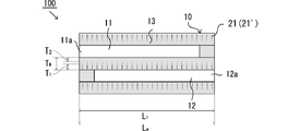
本実施形態の排ガス浄化触媒は、内燃機関から排出される排ガスを浄化する排ガス浄化触媒100であって、排ガス導入側の端部11aが開口した導入側セル11と、該導入側セル11に隣接し排ガス排出側の端部12aが開口した排出側セル12とが、多孔質の隔壁13により画定されたウォールフロー型基材10と、隔壁13の気孔内の複数か所に形成された、少なくとも一種以上の触媒金属を含む触媒層21と、を有し、該触媒層21が、隔壁13の厚さ方向において排出側セル12側に偏在しているものであることを特徴とする。
[Exhaust gas purification catalyst]
The exhaust gas purification catalyst of the present embodiment is an exhaust
以下、図1に示す、本実施形態の排ガス浄化触媒を模式的に示す断面図を参照しつつ、各構成について説明する。本実施形態の排ガス浄化触媒はウォールフロー構造を有する。このような構造を有する排ガス浄化触媒100では、内燃機関から排出される排ガスが、排ガス導入側の端部11a(開口)から導入側セル11内へと流入し、隔壁13の気孔内を通過して隣接する排出側セル12内へ流入し、排ガス排出側の端部12a(開口)から流出する。この過程において、隔壁13の気孔内を通り難い粒子状物質(PM)は、一般に、導入側セル11内の隔壁13上及び/又は隔壁13の気孔内に堆積し、堆積した粒子状物質は、触媒層21の触媒機能によって、或いは所定の温度(例えば500~700℃程度)で燃焼し、除去される。また、排ガスは、隔壁13の気孔内に形成された触媒層21と接触し、これによって排ガスに含まれる一酸化炭素(CO)や炭化水素(HC)は水(H2O)や二酸化炭素(CO2)などへ酸化され、窒素酸化物(NOx)は窒素(N2)へ還元され、有害成分が浄化(無害化)される。なお、本明細書においては、粒子状物質の除去及び一酸化炭素(CO)等の有害成分の浄化をまとめて「排ガス浄化性能」ともいう。以下、各構成についてより詳細に説明する。
Hereinafter, each configuration will be described with reference to the cross-sectional view schematically showing the exhaust gas purification catalyst of the present embodiment shown in FIG. 1. The exhaust gas purification catalyst of this embodiment has a wall flow structure. In the exhaust
(基材)
ウォールフロー型基材10は、排ガス導入側の端部11aが開口した導入側セル11と、該導入側セル11に隣接し排ガス排出側の端部12aが開口した排出側セル12とが、多孔質の隔壁13によって仕切られているウォールフロー構造を有する。
(Base material)
In the wall flow
基材10としては、従来のこの種の用途に用いられる種々の材質及び形体のものが使用可能である。例えば、基材の材質は、内燃機関が高負荷条件で運転された際に生じる高温(例えば400℃以上)の排ガスに曝された場合や、粒子状物質を高温で燃焼除去する場合などにも対応可能なように、耐熱性素材からなるものが好ましい。耐熱性素材としては、例えば、コージェライト、ムライト、チタン酸アルミニウム、及び炭化ケイ素(SiC)等のセラミック;ステンレス鋼などの合金が挙げられる。また、基材の形体は、排ガス浄化性能及び圧力損失上昇抑制等の観点から適宜調整することが可能である。例えば、基材の外形は、円筒形状、楕円筒形状、又は多角筒形状等とすることができる。また、組み込む先のスペースなどにもよるが、基材の容量(セルの総体積)は、好ましくは0.1~5Lであり、より好ましくは0.5~3Lである。また、基材の延伸方向の全長(隔壁13の延伸方向の全長)は、好ましくは10~500mm、より好ましくは50~300mmである。
As the
導入側セル11と排出側セル12は、筒形状の軸方向に沿って規則的に配列されており、隣り合うセル同士は延伸方向の一の開口端と他の一の開口端とが交互に封止されている。導入側セル11及び排出側セル12は、供給される排ガスの流量や成分を考慮して適当な形状および大きさに設定することができる。例えば、導入側セル11及び排出側セル12の口形状は、三角形;正方形、平行四辺形、長方形、及び台形等の矩形;六角形及び八角形等のその他の多角形;円形とすることができる。また、導入側セル11の断面積と、排出側セル12の断面積とを異ならせたHigh Ash Capacity(HAC)構造を有するものであってもよい。なお、導入側セル11及び排出側セル12の個数は、排ガスの乱流の発生を促進し、かつ、排ガスに含まれる微粒子等による目詰まりを抑制できるように適宜設定することができ、特に限定されないが、200cpsi~400cpsiが好ましい。
The introduction-
隣り合うセル同士を仕切る隔壁13は、排ガスが通過可能な多孔質構造を有するものであれば特に制限されず、その構成については、排ガス浄化性能や圧力損失の上昇抑制、基材の機械的強度の向上等の観点から適宜調整することができる。例えば、後述する触媒スラリー21aを用いて該隔壁13内の気孔表面に触媒層21を形成する場合、気孔径(例えば、モード径(気孔径の頻度分布における出現比率がもっとも大きい気孔径(分布の極大値)))や気孔容積が大きい場合には、触媒層21による気孔の閉塞が生じにくく、得られる排ガス浄化触媒は圧力損失が上昇しにくいものとなる傾向にあるが、粒子状物質の捕集能力が低下し、また、基材の機械的強度も低下する傾向にある。一方で、気孔径や気孔容積が小さい場合には、圧力損失が上昇しやすいものとなるが、粒子状物質の捕集能力は向上し、基材の機械的強度も向上する傾向にある。
The
このような観点から、触媒層21を形成する前のウォールフロー型基材10の隔壁13の気孔径(モード径)は、好ましくは8~25μmであり、より好ましくは10~22μmであり、さらに好ましくは13~20μmである。また、隔壁13の厚み(延伸方向に直交する厚さ方向の長さ)は、好ましくは6~12milであり、より好ましくは6~10milである。さらに、水銀圧入法による隔壁13の気孔容積は、好ましくは0.2~1.5cm3/gであり、より好ましくは0.25~0.9cm3/gであり、さらに好ましくは0.3~0.8cm3/gである。また、水銀圧入法による隔壁13の気孔率は、好ましくは20~80%であり、より好ましくは40~70%であり、さらに好ましくは60~70%である。気孔容積又は気孔率が下限以上であることにより、圧力損失の上昇がより抑制される傾向にある。また、気孔容積又は気孔率が上限以下であることにより、基材の強度がより向上する傾向にある。なお、気孔径(モード径)、気孔容積、及び気孔率は、下記実施例に記載の条件において水銀圧入法により算出される値を意味する。
From this point of view, the pore diameter (mode diameter) of the
(触媒層)
次に、触媒層21について説明する。触媒層21は、隔壁13の気孔内の複数か所に形成され、少なくとも一種以上の触媒金属を含み、隔壁13の厚さ方向において排出側セル12側に偏在している(図2)。このような構成を有することにより、排ガス浄化性能を有しつつ、圧力損失、特に、アッシュ堆積後の圧力損失の上昇が抑制される傾向にある。
(Catalyst layer)
Next, the
この理由としては、以下の様な点が考えられる。導入側セル11側に触媒層21が偏在する場合、アッシュは隔壁13内の気孔には入り込まず、導入側セル11の隔壁13表面に堆積し易い傾向にある(図3参照)。不燃成分からなるアッシュは燃焼除去することができないため、アッシュの堆積とともに排ガス浄化触媒の圧力損失は徐々に上昇する。これに対して、排出側セル12側に触媒層21が偏在する場合、不燃成分からなるアッシュは、導入側セル11の隔壁13表面のみならず、導入側セル11側の気孔内に侵入し易いため、同気孔内にも堆積が可能となり(図2参照)、アッシュ堆積後の圧力損失の上昇が抑制されると考えられる。アッシュ堆積後の圧力損失の上昇が抑制されることにより、排ガス浄化触媒の寿命も向上する。但し、アッシュ堆積後の圧力損失の上昇が抑制される理由は、上記に制限されない。
The following points can be considered as the reason for this. When the
触媒層21が偏在する態様は、所望の排ガス浄化性能及びアッシュ堆積後の圧力損失の上昇抑制効果を発揮し得る態様であれば、特に限定されず、触媒層21は、隔壁13の厚さ方向において、排出側セル12側のセル壁面に近いほど担持量が増加する傾向を有することが好ましい。これにより、上記と同様の観点から、アッシュ堆積後の圧力損失の上昇が抑制される傾向にある。
The aspect in which the
このような偏在を示す一つの態様として、隔壁13の壁厚Twとしたとき、排出側セル12側のセル壁面からTw*5/10までの深さ領域T1に、触媒層21の総質量の60%以上が存在することが好ましい。当該深さ領域T1における触媒層21の担持量は、隔壁13の断面の触媒層21の総質量に対して、好ましくは65%以上であり、より好ましくは70%以上であり、さらに好ましくは75%以上である。排出側セル12側のセル壁面からTw*5/10までの深さ領域T1において、触媒層21の担持量が60%以上となるように偏在していることにより、相対的に、導入側セル11側の気孔内に配される触媒層21の担持量が少なくなり、アッシュが堆積可能な空間を確保することができる。
As one aspect showing such uneven distribution, when the wall thickness Tw of the
また、他の態様として、隔壁13の壁厚Twとしたとき、導入側セル11側のセル壁面からTw*3/10までの深さ領域T2に、触媒層21の総質量の15%以下が存在することが好ましい。当該深さ領域T2における触媒層21の担持量は、隔壁13の断面の触媒層21の総質量に対して、好ましくは12%以下であり、より好ましくは10%以下であり、さらに好ましくは8%以下である。導入側セル11側のセル壁面からTw*3/10までの深さ領域T2において、触媒層21の担持量が15%以下となるように偏在していることにより、導入側セル11側の気孔内に配される触媒層21の担持量が少なくなり、アッシュが堆積可能な空間を確保することができる。
Further, as another embodiment, when the wall thickness Tw of the
本実施形態においては、触媒層21が隔壁13の厚さ方向において排出側セル12側に偏って存在してさえいれば、一部の触媒層21が導入側セル11側に存在してもよい。言い換えれば、触媒層21が隔壁13の厚さ方向において排出側セル12側に偏って存在してさえいれば、触媒層21は隔壁13の厚さ方向において、導入側セル11側のセル壁面から排出側セル12側のセル壁面にかけて形成されていてもよい。
In the present embodiment, a part of the
なお、触媒層21の偏在は、排ガス浄化触媒100の隔壁13の断面の走査型電子顕微鏡により確認することができる。具体的には、隔壁13断面の走査型電子顕微鏡写真において、触媒層21が占める部分を特定し、隔壁13の厚さ方向に10分割して各エリア毎に触媒層21の面積をそれぞれ積算することで、求めることができる。この際、隔壁13の排ガス導入側の端部11aに近い部分、排ガス排出側の端部12aに近い部分、及びその間の中央部分、の少なくとも3個所で測定し、その平均値として求めることが望ましい。
The uneven distribution of the
また、隔壁13の延伸方向(長さ方向)において、触媒層21が形成されている範囲L1(触媒層21の塗工長さ)は、ウォールフロー型基材10の延伸方向の全長LW(隔壁13の延伸方向の全長)を100%として、全体にわたって形成されていることが好ましく、具体的には、好ましくは80~100%であり、より好ましくは90~100%であり、さらに好ましくは95~100%である。
Further, in the stretching direction (length direction) of the
触媒層21に含まれる触媒金属としては、特に制限されず、種々の酸化触媒や還元触媒として機能し得る金属種を用いることができる。例えば、白金(Pt)、パラジウム(Pd)、ロジウム(Rh)、ルテニウム(Ru)、イリジウム(Ir)及びオスミウム(Os)等の白金族金属が挙げられる。このなかでも、酸化活性の観点からはパラジウム(Pd)、白金(Pt)が好ましく、還元活性の観点からはロジウム(Rh)が好ましい。本実施形態においては、上記のとおり一種以上の触媒金属を混合された状態で含有する触媒層21を有する。特に二種以上の触媒金属の併用により、異なる触媒活性を有することによる相乗的な効果が期待される。
The catalyst metal contained in the
このような触媒金属の組み合わせの態様は、特に制限されず、酸化活性に優れる二種以上の触媒金属の組み合わせ、還元活性に優れる二種以上の触媒金属の組み合わせ、酸化活性に優れる触媒金属と還元活性に優れる触媒金属の組み合わせが挙げられる。このなかでも、相乗効果の一つの態様として、酸化活性に優れる触媒金属と還元活性に優れる触媒金属の組み合わせが好ましく、Rh、Pd及びRh、または、Pt及びRhを少なくとも含む組合せがより好ましい。このような組み合わせとすることにより、排ガス浄化性能がより向上する傾向にある。 The mode of such a combination of catalyst metals is not particularly limited, and a combination of two or more kinds of catalyst metals having excellent oxidation activity, a combination of two or more kinds of catalyst metals having excellent reduction activity, and a catalyst metal having excellent oxidation activity and reduction Examples thereof include a combination of catalyst metals having excellent activity. Among these, as one aspect of the synergistic effect, a combination of a catalytic metal having excellent oxidative activity and a catalytic metal having excellent reducing activity is preferable, and a combination containing at least Rh, Pd and Rh, or Pt and Rh is more preferable. With such a combination, the exhaust gas purification performance tends to be further improved.
なお、触媒層21が触媒金属を含有することは、排ガス浄化触媒の隔壁13の断面の走査型電子顕微鏡などにより確認することができる。具体的には、走査型電子顕微鏡の視野においてエネルギー分散型X線分析を行うことにより確認することができる。
The fact that the
触媒層21に含まれ、触媒金属を担持する担体粒子としては、従来この種の排ガス浄化用触媒で使用される無機化合物を考慮することができる。例えば、酸化セリウム(セリア:CeO2)、セリア-ジルコニア複合酸化物(CZ複合酸化物)等の酸素吸蔵材(OSC材)、酸化アルミニウム(アルミナ:Al2O3)、酸化ジルコニウム(ジルコニア:ZrO2)、酸化ケイ素(シリカ:SiO2)、酸化チタン(チタニア:TiO2)等の酸化物やこれらの酸化物を主成分とした複合酸化物を挙げることができる。これらは、ランタン、イットリウム等の希土類元素、遷移金属元素、アルカリ土類金属元素が添加された複合酸化物若しくは固溶体であってもよい。なお、これら担体粒子は、一種単独で用いても、二種以上を併用してもよい。ここで、酸素吸蔵材(OSC材)とは、排ガスの空燃比がリーンであるとき(即ち酸素過剰側の雰囲気)には排ガス中の酸素を吸蔵し、排ガスの空燃比がリッチであるとき(即ち燃料過剰側の雰囲気)には吸蔵されている酸素を放出するものをいう。
As the carrier particles contained in the
排ガス浄化性能の向上、触媒金属の粒成長(シンタリング)の進行の抑制などの観点から、触媒層21の触媒金属担持率(基材1Lあたりの触媒金属質量)は、好ましくは0.5~10g/Lであり、より好ましくは1~8g/Lであり、さらに好ましくは1~6g/Lである。
From the viewpoint of improving the exhaust gas purification performance and suppressing the progress of grain growth (sintering) of the catalyst metal, the catalyst metal loading ratio (catalyst metal mass per 1 L of the base material) of the
また、触媒層21が形成された状態の排ガス浄化触媒の水銀圧入法による隔壁13の気孔径(モード径)は、好ましくは10~23μmであり、より好ましくは12~20μmであり、さらに好ましくは14~18μmである。また、触媒層21が形成された状態の排ガス浄化触媒の水銀圧入法による隔壁13の気孔容積は、好ましくは0.2~1.0cm3/gであり、より好ましくは0.25~0.9cm3/gであり、さらに好ましくは0.3~0.8cm3/gである。さらに、触媒層21が形成された状態の排ガス浄化触媒の水銀圧入法による隔壁13の気孔率は、好ましくは20~80%であり、より好ましくは30~70%であり、好ましくは35~60%である。なお、気孔径(モード径)、気孔容積、及び気孔率は、下記実施例に記載の条件において水銀圧入法により算出される値を意味する。
Further, the pore diameter (mode diameter) of the
[排ガス浄化触媒の製造方法]
本実施形態の排ガス浄化触媒の製造方法は、内燃機関から排出される排ガスを浄化する排ガス浄化触媒100の製造方法であって、排ガス導入側の端部11aが開口した導入側セル11と、該導入側セル11に隣接し排ガス排出側の端部12aが開口した排出側セル12とが、多孔質の隔壁13により画定されたウォールフロー型基材10を準備する工程S0と、隔壁13の排出側セル12側に存在する気孔表面上に偏在した触媒層21を形成する触媒層形成工程S1とを有することを特徴とする。
[Manufacturing method of exhaust gas purification catalyst]
The method for manufacturing the exhaust gas purification catalyst of the present embodiment is a method for manufacturing the exhaust
以下、各工程について説明する。なお、本明細書においては、触媒層21を形成する前のウォールフロー型基材を「基材10」と表記し、触媒層21を形成した後のウォールフロー型基材を「排ガス浄化触媒100」と表記する。
Hereinafter, each step will be described. In the present specification, the wall flow type base material before forming the
<準備工程>
この準備工程S0では、基材として、排ガス浄化触媒100において述べたウォールフロー型基材10を準備する。
<Preparation process>
In this preparation step S0, the wall flow
<触媒層形成工程>
この触媒層形成工程S1では、隔壁13の排出側セル12側に存在する気孔表面に触媒スラリー21aを塗工して、乾燥させ、焼成することで、偏在させた触媒層21を形成する。触媒スラリー21aの塗工方法は、特に制限されないが、例えば、基材10の一部に触媒スラリー21aを含浸させて、それを基材10の隔壁13全体に広げる方法が挙げられる。より具体的には、基材10の排ガス排出側の端部12aに、触媒スラリー21aを含浸させる工程S1aと、排ガス排出側の端部12a側から基材10内に気体を導入させることにより、基材10に含浸された触媒スラリー21aを排出側セル12側に存在する気孔表面に塗工する工程S1bを有する方法が挙げられる。
<Catalyst layer formation process>
In this catalyst layer forming step S1, the catalyst slurry 21a is applied to the pore surface existing on the
隔壁13の排出側セル12側に触媒層21を偏在させる方法としては、隔壁13の排出側セル12側に触媒スラリー21aを塗工し、塗工した触媒スラリー21aを乾燥、焼成させる方法であれば、特に制限されない。例えば、隔壁13の排出側セル12側に対して、隔壁13内の気孔への浸透距離を調整するために触媒スラリー21aの粘度や固形分を調整したり、必要に応じて塗工条件や塗工後の乾燥条件も調整する方法が挙げられる。
As a method of unevenly distributing the
工程S1aにおける触媒スラリー21aの含浸方法としては、特に制限されないが、例えば、触媒スラリー21aに基材10の端部を浸漬させる方法が挙げられる。この方法においては、必要に応じて、反対側の端部から気体を排出(吸引)させることにより触媒スラリー21aを引き上げてもよい。触媒スラリー21aは、排ガス排出側の端部12aからウォールフロー型基材10内に供給する。
The method of impregnating the catalyst slurry 21a in the step S1a is not particularly limited, and examples thereof include a method of immersing the end portion of the
また、工程S1bでは、触媒スラリー21aを含浸させた端部側から基材10内に気体を導入させて、排出側セル12側に存在する気孔に触媒スラリー21aを塗工する。触媒スラリー21aを塗工する方法としては、基材10の両端部に気圧差を生じさせる方法が挙げられる。具体的には、排ガス排出側の端部12aを相対的に高気圧として、排ガス排出側の端部12aから含浸させた触媒スラリー21aが排ガス導入側の端部11a側へ向かって塗工されるよう圧力をかけることにより、触媒スラリー21aを塗工することができる。
Further, in step S1b, gas is introduced into the
工程S1cでは、塗工された触媒スラリー21aを乾燥させて乾燥した触媒スラリー21a’とする。工程S1cにおける乾燥条件は、触媒スラリー21aから溶媒が揮発するような条件であれば特に制限されない。例えば、乾燥温度は、好ましくは100~225℃であり、より好ましくは100~200℃であり、さらに好ましくは125~175℃である。また、乾燥時間は、好ましくは0.5~2時間であり、好ましくは0.5~1.5時間である。 In step S1c, the coated catalyst slurry 21a is dried to obtain a dried catalyst slurry 21a'. The drying conditions in step S1c are not particularly limited as long as the solvent volatilizes from the catalyst slurry 21a. For example, the drying temperature is preferably 100 to 225 ° C, more preferably 100 to 200 ° C, and even more preferably 125 to 175 ° C. The drying time is preferably 0.5 to 2 hours, preferably 0.5 to 1.5 hours.
乾燥方法として考えられる方法としては、工程S1b後の基材10を所定の乾燥温度で静置する方法の他、排ガス導入側及び/又は排ガス排出側の端部11a,12aから、基材10内に気体Fを導入させて乾燥を促進する方法が挙げられる。
As a method considered as a drying method, in addition to a method in which the
次いで、工程S1dでは、上記のようにして乾燥させた触媒スラリー21a’を焼成して、触媒層21を形成する。工程S1dにおける焼成条件は、乾燥させた触媒スラリー21a’から触媒層21が形成できるような条件であれば特に制限されない。例えば、焼成温度は、特に制限されないが、好ましくは400~650℃であり、より好ましくは450~600℃であり、さらに好ましくは500~600℃である。また、焼成時間は、好ましくは0.5~2時間であり、好ましくは0.5~1.5時間である。
Next, in step S1d, the catalyst slurry 21a'dried as described above is fired to form the
(触媒スラリー)
触媒層21を形成するための触媒スラリー21aについて説明する。触媒スラリー21aは、触媒粉体と、水などの溶剤とを含む。触媒粉体は、触媒金属粒子と該触媒金属粒子を担持する担体粒子とを含む、複数の触媒粒子の集団であり、後述する焼成工程を経て、触媒層21を形成する。触媒粒子は、特に限定されず、公知の触媒粒子から適宜選択して用いることができる。なお、隔壁13の気孔内への塗工性の観点から、触媒スラリー21aの固形分率は、好ましくは1~50質量%であり、より好ましくは10~40質量%であり、さらに好ましくは15~30質量%である。このような固形分率とすることにより、触媒スラリー21aを隔壁13内の排出側セル12側に塗工しやすくなる傾向にある。
(Catalyst slurry)
The catalyst slurry 21a for forming the
触媒スラリー21aに含まれる触媒粉体のD90粒子径は、好ましくは1~7μmであり、より好ましくは1~6μmであり、さらに好ましくは1~5μmである。D90粒子径が1μm以上であることにより、触媒粉体をミリング装置で破砕する場合の粉砕時間を短縮することができ、作業効率がより向上する傾向にある。また、D90粒子径が7μm以下であることにより、粗大粒子が隔壁13内の気孔を閉塞することが抑制され、圧力損失の上昇が抑制される傾向にある。なお、本明細書において、D90粒子径は、レーザー回折式粒子径分布測定装置(例えば、島津製作所社製、レーザー回折式粒子径分布測定装置SALD-3100等)で測定することができる。
The D90 particle size of the catalyst powder contained in the catalyst slurry 21a is preferably 1 to 7 μm, more preferably 1 to 6 μm, and further preferably 1 to 5 μm. When the D90 particle size is 1 μm or more, the crushing time when the catalyst powder is crushed by the milling device can be shortened, and the work efficiency tends to be further improved. Further, when the D90 particle diameter is 7 μm or less, it is suppressed that the coarse particles block the pores in the
触媒スラリー21aに含まれる触媒金属としては、種々の酸化触媒や還元触媒として機能し得る金属種を二種以上組み合わせて用いることができる。具体的には、触媒層21に含まれる触媒金属で例示したものと同様のものが挙げられる。一つの態様として、触媒スラリー21aに含まれる触媒金属の組み合わせについては、これら触媒スラリー21aにより形成された触媒層21において説明した態様と同様の態様が例示される。具体的には、酸化活性に優れる二種以上の触媒金属の組み合わせ、還元活性に優れる二種以上の触媒金属の組み合わせ、酸化活性に優れる触媒金属と還元活性に優れる触媒金属の組み合わせが挙げられる。このなかでも、相乗効果の一つの態様として、酸化活性に優れる触媒金属と還元活性に優れる触媒金属の組み合わせが好ましく、Pd及びRhを少なくとも含む組合せがより好ましい。
As the catalyst metal contained in the catalyst slurry 21a, two or more kinds of metals that can function as various oxidation catalysts and reduction catalysts can be used in combination. Specifically, the same as those exemplified for the catalyst metal contained in the
排ガスとの接触面積を高める観点から、触媒スラリー21a中の触媒金属粒子の平均粒子径は小さいことが好ましい。具体的には、触媒金属粒子の平均粒子径は、好ましくは1~15nmであり、より好ましくは1~10nmであり、さらに好ましくは1~7nmである。なお、触媒金属粒子の平均粒子径は、例えば日立ハイテクノロジーズ社製HD-2000等の走査型透過電子顕微鏡(STEM:Scanning Transmission Electron Microscope)を用いて確認することができ、本明細書では、無作為に抽出した10点の触媒金属粒子の円相当径を算出し、これらの平均値を触媒金属粒子の平均粒子径とする。 From the viewpoint of increasing the contact area with the exhaust gas, it is preferable that the average particle size of the catalyst metal particles in the catalyst slurry 21a is small. Specifically, the average particle size of the catalyst metal particles is preferably 1 to 15 nm, more preferably 1 to 10 nm, and even more preferably 1 to 7 nm. The average particle size of the catalyst metal particles can be confirmed by using, for example, a scanning transmission electron microscope (STEM) such as HD-2000 manufactured by Hitachi High-Technologies Co., Ltd., which is not described in the present specification. The circle-equivalent diameters of the 10 catalytic metal particles extracted at random are calculated, and the average value thereof is taken as the average particle diameter of the catalytic metal particles.
触媒スラリー21aに含まれる担体粒子としては、従来この種の排ガス浄化用触媒で使用される無機化合物を考慮することができる。具体的には、触媒層21に含まれる担体粒子で例示したものと同様のものが挙げられる。なお、これら担体粒子は、一種単独で用いても、二種以上を併用してもよい。
As the carrier particles contained in the catalyst slurry 21a, an inorganic compound conventionally used in this type of exhaust gas purification catalyst can be considered. Specifically, the same as those exemplified for the carrier particles contained in the
排ガス浄化性能の観点から、触媒スラリー21aに含まれる担体粒子の比表面積は、好ましくは10~500m2/g、より好ましくは30~200m2/gである。 From the viewpoint of exhaust gas purification performance, the specific surface area of the carrier particles contained in the catalyst slurry 21a is preferably 10 to 500 m 2 / g, more preferably 30 to 200 m 2 / g.
また、排ガス浄化性能の向上や、触媒金属の粒成長(シンタリング)の進行の抑制などの観点から、ウォールフロー型基材10に担持させた状態の、触媒スラリー21aに由来する触媒金属担持率(基材1Lあたりの触媒金属質量)は、好ましくは0.5~10g/Lであり、より好ましくは1~8g/Lであり、さらに好ましくは1~6g/Lである。 Further, from the viewpoint of improving the exhaust gas purification performance and suppressing the progress of grain growth (sintering) of the catalyst metal, the catalyst metal loading ratio derived from the catalyst slurry 21a in the state of being supported on the wall flow type base material 10 (Catalyst metal mass per 1 L of the substrate) is preferably 0.5 to 10 g / L, more preferably 1 to 8 g / L, and further preferably 1 to 6 g / L.
[用途]
内燃機関(エンジン)には、酸素と燃料ガスとを含む混合気が供給され、この混合気が燃焼されて、燃焼エネルギーが力学的エネルギーに変換される。このときに燃焼された混合気は排ガスとなって排気系に排出される。排気系には、排ガス浄化触媒を備える排ガス浄化装置が設けられており、排ガス浄化触媒により排ガスに含まれる有害成分(例えば、一酸化炭素(CO)、炭化水素(HC)、窒素酸化物(NOx))が浄化されるとともに、排ガスに含まれる粒子状物質(PM)が捕集され、除去される。特に、本実施形態の排ガス浄化触媒100は、ガソリンエンジンの排ガスに含まれる粒子状物質を捕集し、除去できるガソリンパティキュレートフィルタ(GPF)に用いられるものであることが好ましい。
[Use]
An air-fuel mixture containing oxygen and fuel gas is supplied to an internal combustion engine (engine), and the air-fuel mixture is burned to convert combustion energy into mechanical energy. The air-fuel mixture burned at this time becomes exhaust gas and is discharged to the exhaust system. The exhaust system is provided with an exhaust gas purification device equipped with an exhaust gas purification catalyst, and harmful components (for example, carbon monoxide (CO), hydrocarbons (HC), nitrogen oxides (NOx) contained in the exhaust gas by the exhaust gas purification catalyst are provided. )) Is purified, and particulate matter (PM) contained in the exhaust gas is collected and removed. In particular, the exhaust
以下に試験例、実施例と比較例を挙げて本発明の特徴をさらに具体的に説明するが、本発明は、これらによりなんら限定されるものではない。すなわち、以下の実施例に示す材料、使用量、割合、処理内容、処理手順等は、本発明の趣旨を逸脱しない限り、適宜変更することができる。また、以下の実施例における各種の製造条件や評価結果の値は、本発明の実施態様における好ましい上限値又は好ましい下限値としての意味をもつものであり、好ましい範囲は前記した上限又は下限の値と、下記実施例の値又は実施例同士の値との組み合わせで規定される範囲であってもよい。 Hereinafter, the features of the present invention will be described in more detail with reference to Test Examples, Examples and Comparative Examples, but the present invention is not limited thereto. That is, the materials, amounts used, ratios, treatment contents, treatment procedures, etc. shown in the following examples can be appropriately changed as long as they do not deviate from the gist of the present invention. Further, the values of various production conditions and evaluation results in the following examples have meanings as a preferable upper limit value or a preferable lower limit value in the embodiment of the present invention, and the preferable range is the above-mentioned upper limit value or the lower limit value. And may be in the range specified by the combination of the values of the following examples or the values of the examples.
(実施例1)
D50粒子径が28μm、BET比表面積が141m2/gのアルミナ粉末に、硝酸パラジウム水溶液を含浸させ、その後、500℃で1時間焼成して、Pd担持アルミナ粉末(Pd含有量:8.6質量%)を得た。また、D50粒子径が29μm、BET比表面積が145m2/gのジルコニア-ランタン修飾アルミナ粉末に、硝酸ロジウム水溶液を含浸させ、その後、500℃で1時間焼成して、Rh担持ジルコニア-ランタン修飾アルミナ粉末(Rh含有量:1.4質量%)を得た。
(Example 1)
Alumina powder having a D50 particle size of 28 μm and a BET specific surface area of 141 m 2 / g is impregnated with an aqueous solution of palladium nitrate and then fired at 500 ° C. for 1 hour to obtain Pd-supported alumina powder (Pd content: 8.6 mass). %) Was obtained. Further, a zirconia-lanthanate-modified alumina powder having a D50 particle diameter of 29 μm and a BET specific surface area of 145 m 2 / g was impregnated with a rhodium nitrate aqueous solution and then calcined at 500 ° C. for 1 hour to carry Rh-supported zirconia-lanthanate-modified alumina. A powder (Rh content: 1.4% by mass) was obtained.
得られたPd担持アルミナ粉末0.5kg及びRh担持ジルコニア-ランタン修飾アルミナ粉末0.5kgと、D50粒子径が10μm、BET比表面積が71m2/gのセリアジルコニア複合酸化物粉末2kgと、46%硝酸ランタン水溶液195gと、イオン交換水とを混合し、得られた混合物をボールミルに投入し、触媒粉体が所定の粒子径分布になるまでミリングし、D90粒子径が3.0μmの触媒スラリーを得た。 0.5 kg of Pd-supported alumina powder and 0.5 kg of Rh-supported zirconia-lantern-modified alumina powder, and 2 kg of ceria zirconia composite oxide powder having a D50 particle size of 10 μm and a BET specific surface area of 71 m 2 / g, 46%. 195 g of an aqueous solution of lanthanum nitrate and ion-exchanged water are mixed, and the obtained mixture is put into a ball mill and milled until the catalyst powder has a predetermined particle size distribution to obtain a catalyst slurry having a D90 particle size of 3.0 μm. Obtained.
次いで、コージェライト製のウォールフロー型ハニカム基材(セル数/ミル厚:300cpsi/8mil、直径:118.4mm、全長:127mm、気孔率:65%)を用意した。この基材の排ガス排出側の端部を触媒スラリーに浸漬させ、反対側の端部側から減圧吸引して、基材端部に触媒スラリーを含浸保持させた。触媒スラリーを含浸保持させた端面側から基材内へ気体を流入させて、隔壁内の気孔表面に、厚さ方向において排出側セル側に偏在するよう触媒スラリーを塗工するとともに、基材の排ガス導入側の端部から過剰分の触媒スラリーを吹き払った。その後、基材内へ気体を流入させつつ触媒スラリーを塗工した基材を150℃で乾燥させた後、大気雰囲気下、550℃で焼成した。これにより、封止された開口端から排ガス排出側の開口端部にかけて、厚さ方向において排出側セル側に偏在した触媒層を有する排ガス浄化触媒を作製した。なお、この排ガス浄化触媒において、触媒層は、隔壁13の延伸方向(長さ方向)においては、ウォールフロー型基材10の全長Lwの全体に亘り形成されており、隔壁の厚さ方向においては、導入側セル側のセル壁面から排出側セル側のセル壁面にかけて形成されており、当該触媒層は、排出側セル側のセル壁面に近いほど担持率が増加する傾向を有し、排出側セル側のセル壁面からTw*5/10までの深さ領域に触媒層の総質量の60%以上が存在し、導入側セル側のセル壁面からTw*3/10までの深さ領域に触媒層の総質量の15%以下が存在するものであった。なお、焼成後における触媒層の塗工量は、基材1L当たり60.9g(白金族金属の重量を除く)であった。
Next, a wall-flow type honeycomb substrate made of Cordellite (number of cells / mill thickness: 300 cpsi / 8 mil, diameter: 118.4 mm, total length: 127 mm, porosity: 65%) was prepared. The end portion of the base material on the exhaust gas discharge side was immersed in the catalyst slurry and sucked under reduced pressure from the opposite end side to impregnate and hold the catalyst slurry on the end portion of the base material. Gas flows into the base material from the end face side impregnated and held with the catalyst slurry, and the catalyst slurry is applied to the pore surface in the partition wall so as to be unevenly distributed on the discharge side cell side in the thickness direction, and the base material is coated with the catalyst slurry. The excess catalyst slurry was blown off from the end on the exhaust gas introduction side. Then, the base material coated with the catalyst slurry was dried at 150 ° C. while allowing gas to flow into the base material, and then calcined at 550 ° C. under an atmospheric atmosphere. As a result, an exhaust gas purification catalyst having a catalyst layer unevenly distributed on the discharge side cell side in the thickness direction from the sealed end to the exhaust gas discharge side opening end was produced. In this exhaust gas purification catalyst, the catalyst layer is formed over the entire total length Lw of the wall flow
(比較例1)
導入側セル側の端部を触媒スラリーに浸漬させ、反対側の端部側から減圧吸引して、基材端部に触媒スラリーを含浸保持させ、触媒スラリーを含浸保持させた端面側から基材内へ気体を流入させて、隔壁内の気孔表面に、厚さ方向において導入側セル側に偏在するよう触媒スラリーを塗工するとともに、基材の排ガス排出側の端部から過剰分の触媒スラリーを吹き払ったこと以外は、実施例1と同様の操作により、封止された開口端から排ガス導入側の開口端部にかけて、厚さ方向において導入側セル側に偏在した触媒層を有する排ガス浄化触媒を作製した。
(Comparative Example 1)
The end of the cell on the introduction side is immersed in the catalyst slurry and sucked under reduced pressure from the opposite end side to impregnate and hold the catalyst slurry on the end of the base material, and the base material is impregnated and held from the end face side where the catalyst slurry is impregnated and held. The gas is allowed to flow in, and the catalyst slurry is coated on the pore surface in the partition wall so as to be unevenly distributed on the introduction side cell side in the thickness direction, and the excess catalyst slurry is applied from the end portion of the base material on the exhaust gas discharge side. Exhaust gas purification having a catalyst layer unevenly distributed on the introduction side cell side in the thickness direction from the sealed opening end to the exhaust gas introduction side opening end by the same operation as in Example 1 except that A catalyst was prepared.
(比較例2)
コージェライト製のウォールフロー型ハニカム基材(セル数/ミル厚:300cpsi/8mil、直径:118.4mm、全長:127mm、気孔率:65%)を用意した。この基材の排ガス導入側の端部を触媒スラリーに浸漬させ、反対側の端部側から減圧吸引して、基材端部に触媒スラリーを含浸保持させた。触媒スラリーを含浸保持させた端面側から基材内へ気体を流入させて、隔壁内の気孔表面に、厚さ方向において導入側セル側に偏在するよう触媒スラリーを塗工するとともに、基材の排ガス排出側の端部から過剰分の触媒スラリーを吹き払った。なお、この時の触媒量は最終的な総質量の半分量となるようにした。その後、基材内へ気体を流入させつつ触媒スラリーを塗工した基材を150℃で乾燥させた後、大気雰囲気下、550℃で焼成した。これにより、封止された開口端から排ガス導入側の開口端部にかけて、厚さ方向において導入側セル側に触媒金属が偏在した触媒層を形成した。
(Comparative Example 2)
A wall flow type honeycomb base material made of Cordellite (number of cells / mill thickness: 300 cpsi / 8 mil, diameter: 118.4 mm, total length: 127 mm, porosity: 65%) was prepared. The end portion of the base material on the exhaust gas introduction side was immersed in the catalyst slurry and sucked under reduced pressure from the opposite end side to impregnate and hold the catalyst slurry on the end portion of the base material. Gas is allowed to flow into the base material from the end face side impregnated and held with the catalyst slurry, and the catalyst slurry is applied to the pore surface in the partition wall so as to be unevenly distributed on the introduction side cell side in the thickness direction, and the base material is coated with the catalyst slurry. The excess catalyst slurry was blown off from the end on the exhaust gas discharge side. The amount of catalyst at this time was set to half the final total mass. Then, the base material coated with the catalyst slurry was dried at 150 ° C. while allowing gas to flow into the base material, and then calcined at 550 ° C. under an atmospheric atmosphere. As a result, a catalyst layer in which the catalyst metal is unevenly distributed on the introduction side cell side in the thickness direction is formed from the sealed end to the opening end on the exhaust gas introduction side.
また、同様にして、基材の排ガス排出側の端部を触媒スラリーに浸漬させ、反対側の端部側から減圧吸引して、基材端部に触媒スラリーを含浸保持させた。触媒スラリーを含浸保持させた端面側から基材内へ気体を流入させて、隔壁内の気孔表面に、厚さ方向において排出側セル側に偏在するよう触媒スラリーを塗工するとともに、基材の排ガス導入側の端部から過剰分の触媒スラリーを吹き払った。なお、この時の触媒量は上記と同様に、最終的な総質量の半分量となるようにした。その後、基材内へ気体を流入させつつ触媒スラリーを塗工した基材を150℃で乾燥させた後、大気雰囲気下、550℃で焼成した。これにより、封止された開口端から排ガス排出側の開口端部にかけて、厚さ方向において排出側セル側に触媒金属が偏在した触媒層を形成し、結果として、隔壁全体に亘り略均一に存在する触媒層を有する排ガス浄化触媒を作製した。なお、焼成後における触媒層の塗工量は、基材1L当たり60.9g(白金族金属の重量を除く)であった。 Further, in the same manner, the end portion of the base material on the exhaust gas discharge side was immersed in the catalyst slurry and sucked under reduced pressure from the end portion on the opposite side to impregnate and hold the catalyst slurry on the end portion of the base material. Gas flows into the base material from the end face side impregnated and held with the catalyst slurry, and the catalyst slurry is applied to the pore surface in the partition wall so as to be unevenly distributed on the discharge side cell side in the thickness direction, and the base material is coated with the catalyst slurry. The excess catalyst slurry was blown off from the end on the exhaust gas introduction side. The amount of catalyst at this time was set to be half of the final total mass in the same manner as above. Then, the base material coated with the catalyst slurry was dried at 150 ° C. while allowing gas to flow into the base material, and then calcined at 550 ° C. under an atmospheric atmosphere. As a result, a catalyst layer in which the catalyst metal is unevenly distributed on the discharge side cell side in the thickness direction is formed from the sealed open end to the open end on the exhaust gas discharge side, and as a result, the catalyst layer is substantially uniformly present over the entire partition wall. An exhaust gas purification catalyst having a catalyst layer was produced. The amount of the catalyst layer coated after firing was 60.9 g per 1 L of the base material (excluding the weight of the platinum group metal).
[粒子径分布測定]
触媒スラリーのD90粒子径は、島津製作所社製レーザー回折式粒子径分布測定装置SALD-3100を用いて、レーザー散乱法により測定した。
[Measurement of particle size distribution]
The D90 particle size of the catalyst slurry was measured by a laser scattering method using a laser diffraction type particle size distribution measuring device SALD-3100 manufactured by Shimadzu Corporation.
[気孔率の算出]
実施例及び比較例で作製した排ガス浄化触媒、並びに、触媒スラリーを塗工する前の基材の、排ガス導入側部分、排ガス排出側部分、及び中間部分の各隔壁から、気孔径(モード径)及び気孔容積の測定用サンプル(1cm3)をそれぞれ採取した。測定用サンプルを乾燥後、水銀ポロシメーター(Thermo Fisher Scientific社製、商品名:PASCAL140及びPASCAL440)を用いて、水銀圧入法により気孔分布を測定した。この際、PASCAL140により低圧領域(0~400Kpa)を測定し、PASCAL440により高圧領域(0.1Mpa~400Mpa)を測定した。得られた気孔分布から、気孔径(モード径)を求め、また、気孔径1μm以上の気孔における気孔容積を算出した。なお、気孔径及び気孔容積の値としては、排ガス導入側部分、排ガス排出側部分、及び中間部分それぞれで得られた値の平均値を採用した。
[Calculation of porosity]
Pore diameter (mode diameter) from each partition wall of the exhaust gas introduction side portion, the exhaust gas discharge side portion, and the intermediate portion of the exhaust gas purification catalyst produced in Examples and Comparative Examples and the base material before coating the catalyst slurry. And a sample (1 cm 3 ) for measuring the pore volume was collected. After the measurement sample was dried, the pore distribution was measured by a mercury intrusion method using a mercury porosimeter (manufactured by Thermo Fisher Scientific, trade names: PASCAL 140 and PASCAL 440). At this time, the low pressure region (0 to 400 Kpa) was measured by PASCAL 140, and the high pressure region (0.1 Mpa to 400 Mpa) was measured by PASCAL 440. From the obtained pore distribution, the pore diameter (mode diameter) was obtained, and the pore volume in the pores having a pore diameter of 1 μm or more was calculated. As the values of the pore diameter and the pore volume, the average value of the values obtained in each of the exhaust gas introduction side portion, the exhaust gas discharge side portion, and the intermediate portion was adopted.
次いで、下記式により、実施例及び比較例で作製した排ガス浄化触媒の気孔率を算出した。その結果を、下記表1に示す。
排ガス浄化触媒の気孔率(%)=排ガス浄化触媒の気孔容積(cc/g)÷基材の気孔容積(cc/g)×基材の気孔率(%)
基材の気孔率(%)=65%

Porosity of exhaust gas purification catalyst (%) = Porosity of exhaust gas purification catalyst (cc / g) ÷ Porosity of base material (cc / g) x Porosity of base material (%)
Porosity of the substrate (%) = 65%
[アッシュ堆積前の圧力損失の測定]
実施例及び比較例で作製した排ガス浄化触媒を圧力損失測定装置(ツクバリカセイキ株式会社製)にそれぞれ設置し、設置した排ガス浄化触媒に室温の空気を流入させた。排ガス浄化触媒からの空気の流出量が2m3/minとなったときの空気の導入側と排出側の差圧を測定して得られた値を、排ガス浄化触媒の圧力損失とした。その結果を図4に示す。図4に示されるとおり、実施例で作製した排ガス浄化触媒は、比較例で作製した排ガス浄化触媒と同等の圧力損失を有し、触媒層の位置によっては、アッシュ堆積前の圧力損失に差がないことがわかる。
[Measurement of pressure loss before ash deposition]
The exhaust gas purification catalysts produced in Examples and Comparative Examples were installed in pressure loss measuring devices (manufactured by Tsukubarika Seiki Co., Ltd.), and air at room temperature was allowed to flow into the installed exhaust gas purification catalysts. The value obtained by measuring the differential pressure between the introduction side and the exhaust side of the air when the amount of air outflow from the exhaust gas purification catalyst was 2 m 3 / min was defined as the pressure loss of the exhaust gas purification catalyst. The results are shown in FIG. As shown in FIG. 4, the exhaust gas purification catalyst produced in the example has the same pressure loss as the exhaust gas purification catalyst produced in the comparative example, and the pressure loss before ash deposition differs depending on the position of the catalyst layer. It turns out that there is no such thing.
[アッシュ堆積後の圧力損失の測定]
実施例及び比較例で作製した排ガス浄化触媒にアッシュを100g堆積させた後の排ガス浄化触媒を用いたこと以外は、上記と同様にして、アッシュ堆積後の圧力損失の測定を行った。その結果を図5に示す。図5に示されるとおり、実施例で作製した排ガス浄化触媒は、比較例で作製した排ガス浄化触媒より低い圧力損失を有し、触媒層の位置によっては、アッシュ堆積後の圧力損失に差があることがわかる。
[Measurement of pressure loss after ash deposition]
The pressure loss after ash deposition was measured in the same manner as above, except that the exhaust gas purification catalyst after depositing 100 g of ash was used in the exhaust gas purification catalyst produced in Examples and Comparative Examples. The results are shown in FIG. As shown in FIG. 5, the exhaust gas purification catalyst produced in the example has a lower pressure loss than the exhaust gas purification catalyst produced in the comparative example, and there is a difference in the pressure loss after ash deposition depending on the position of the catalyst layer. You can see that.
[コート状態観察]
実施例及び比較例で作製した排ガス浄化触媒の隔壁から走査型電子顕微鏡(SEM)の測定用サンプル(1cm3)をそれぞれ作製した。測定用サンプルを樹脂に埋め、カーボン蒸着の前処理を行なった。前処理後の測定用サンプルを、走査型電子顕微鏡(Carl Zeiss社製、商品名:ULTRA55)を用いて観察し、基材への触媒の担持状態を確認した。そのトレース図を図6に示す。
[Observation of coat condition]
Measurement samples (1 cm 3 ) of a scanning electron microscope (SEM) were prepared from the partition walls of the exhaust gas purification catalysts prepared in Examples and Comparative Examples, respectively. The measurement sample was embedded in resin and pretreated for carbon vapor deposition. The measurement sample after the pretreatment was observed using a scanning electron microscope (manufactured by Carl Zeiss, trade name: ULTRA55), and the state of supporting the catalyst on the substrate was confirmed. The trace diagram is shown in FIG.
本発明の排ガス浄化触媒は、ガソリンエンジンの排ガス中に含まれる粒子状物質を除去するため排ガス浄化触媒として広く且つ有効に利用することができる。また、本発明の排ガス浄化触媒は、ガソリンエンジンのみならず、ディーゼルエンジン、ジェットエンジン、ボイラー、ガスタービン等の排ガス中に含まれる粒子状物質を除去するため排ガス浄化触媒としても有効に利用可能である。 The exhaust gas purification catalyst of the present invention can be widely and effectively used as an exhaust gas purification catalyst for removing particulate matter contained in the exhaust gas of a gasoline engine. Further, the exhaust gas purification catalyst of the present invention can be effectively used as an exhaust gas purification catalyst because it removes particulate matter contained in exhaust gas of not only gasoline engines but also diesel engines, jet engines, boilers, gas turbines and the like. be.
10 ・・・ウォールフロー型基材
11 ・・・導入側セル
11a・・・排ガス導入側の端部
12 ・・・排出側セル
12a・・・排ガス排出側の端部
13 ・・・隔壁
21 ・・・触媒層
21a・・・触媒スラリー
21a’・・乾燥した触媒スラリー
100 ・・・排ガス浄化触媒
10 ・ ・ ・ Wall flow
Claims (5)
排ガス導入側の端部が開口した導入側セルと、該導入側セルに隣接し排ガス排出側の端部が開口した排出側セルとが、多孔質の隔壁により画定されたウォールフロー型基材と、
前記隔壁の気孔内の複数か所に形成された、少なくとも一種以上の触媒金属を含む触媒層と、を有し、
該触媒層が、前記隔壁の厚さ方向において、前記排出側セル側に偏在しており、
前記触媒層は、前記隔壁の厚さ方向において、前記排出側セル側のセル壁面に近いほど担持率が増加する傾向を有する、
排ガス浄化触媒。 An exhaust gas purification catalyst that purifies the exhaust gas emitted from an internal combustion engine.
An introduction-side cell having an open end on the exhaust gas introduction side and an exhaust-side cell adjacent to the introduction-side cell and having an open end on the exhaust gas discharge side are defined as a wall-flow type base material by a porous partition wall. ,
It has a catalyst layer containing at least one kind of catalyst metal, which is formed at a plurality of places in the pores of the partition wall.
The catalyst layer is unevenly distributed on the discharge side cell side in the thickness direction of the partition wall .
The catalyst layer has a tendency to increase the loading ratio as it is closer to the cell wall surface on the discharge side cell side in the thickness direction of the partition wall.
Exhaust gas purification catalyst.
排ガス導入側の端部が開口した導入側セルと、該導入側セルに隣接し排ガス排出側の端部が開口した排出側セルとが、多孔質の隔壁により画定されたウォールフロー型基材と、
前記隔壁の気孔内の複数か所に形成された、少なくとも一種以上の触媒金属を含む触媒層と、を有し、
該触媒層が、前記隔壁の厚さ方向において、前記排出側セル側に偏在しており、
前記隔壁の壁厚Twとしたとき、前記排出側セル側のセル壁面からTw*5/10までの深さ領域に、前記触媒層の総質量の60%以上が存在する、
排ガス浄化触媒。 An exhaust gas purification catalyst that purifies the exhaust gas emitted from an internal combustion engine.
An introduction-side cell having an open end on the exhaust gas introduction side and an exhaust-side cell adjacent to the introduction-side cell and having an open end on the exhaust gas discharge side are defined as a wall-flow type base material by a porous partition wall. ,
It has a catalyst layer containing at least one kind of catalyst metal, which is formed at a plurality of places in the pores of the partition wall.
The catalyst layer is unevenly distributed on the discharge side cell side in the thickness direction of the partition wall .
When the wall thickness of the partition wall is Tw, 60% or more of the total mass of the catalyst layer is present in the depth region from the cell wall surface on the discharge side cell side to Tw * 5/10.
Exhaust gas purification catalyst.
排ガス導入側の端部が開口した導入側セルと、該導入側セルに隣接し排ガス排出側の端部が開口した排出側セルとが、多孔質の隔壁により画定されたウォールフロー型基材と、
前記隔壁の気孔内の複数か所に形成された、少なくとも一種以上の触媒金属を含む触媒層と、を有し、
該触媒層が、前記隔壁の厚さ方向において、前記排出側セル側に偏在しており、
前記隔壁の壁厚Twとしたとき、前記導入側セル側のセル壁面からTw*3/10までの深さ領域に、前記触媒層の総質量の15%以下が存在する、
排ガス浄化触媒。 An exhaust gas purification catalyst that purifies the exhaust gas emitted from an internal combustion engine.
An introduction-side cell having an open end on the exhaust gas introduction side and an exhaust-side cell adjacent to the introduction-side cell and having an open end on the exhaust gas discharge side are defined as a wall-flow type base material by a porous partition wall. ,
It has a catalyst layer containing at least one kind of catalyst metal, which is formed at a plurality of places in the pores of the partition wall.
The catalyst layer is unevenly distributed on the discharge side cell side in the thickness direction of the partition wall .
When the wall thickness of the partition wall is Tw, 15% or less of the total mass of the catalyst layer exists in the depth region from the cell wall surface on the introduction side cell side to Tw * 3/10.
Exhaust gas purification catalyst.
請求項1~3のいずれか一項に記載の排ガス浄化触媒。 The catalyst metal comprises Rh, Pd and Rh, or Pt and Rh.
The exhaust gas purification catalyst according to any one of claims 1 to 3 .
請求項1~4のいずれか一項に記載の排ガス浄化触媒。 The internal combustion engine is a gasoline engine.
The exhaust gas purification catalyst according to any one of claims 1 to 4 .
Priority Applications (4)
| Application Number | Priority Date | Filing Date | Title |
|---|---|---|---|
| JP2018095584A JP7051186B2 (en) | 2018-05-17 | 2018-05-17 | Exhaust gas purification catalyst |
| PCT/JP2019/019432 WO2019221214A1 (en) | 2018-05-17 | 2019-05-16 | Exhaust gas purifying catalyst |
| EP19803997.6A EP3795247A4 (en) | 2018-05-17 | 2019-05-16 | EXHAUST PURIFICATION CATALYST |
| CN201980012649.6A CN111699038A (en) | 2018-05-17 | 2019-05-16 | Exhaust gas purifying catalyst |
Applications Claiming Priority (1)
| Application Number | Priority Date | Filing Date | Title |
|---|---|---|---|
| JP2018095584A JP7051186B2 (en) | 2018-05-17 | 2018-05-17 | Exhaust gas purification catalyst |
Publications (2)
| Publication Number | Publication Date |
|---|---|
| JP2019198838A JP2019198838A (en) | 2019-11-21 |
| JP7051186B2 true JP7051186B2 (en) | 2022-04-11 |
Family
ID=68612703
Family Applications (1)
| Application Number | Title | Priority Date | Filing Date |
|---|---|---|---|
| JP2018095584A Active JP7051186B2 (en) | 2018-05-17 | 2018-05-17 | Exhaust gas purification catalyst |
Country Status (1)
| Country | Link |
|---|---|
| JP (1) | JP7051186B2 (en) |
Families Citing this family (3)
| Publication number | Priority date | Publication date | Assignee | Title |
|---|---|---|---|---|
| JP7388951B2 (en) * | 2020-03-04 | 2023-11-29 | トヨタ自動車株式会社 | Exhaust gas purification device |
| JPWO2022172584A1 (en) | 2021-02-09 | 2022-08-18 | ||
| EP4474052A1 (en) * | 2022-03-01 | 2024-12-11 | Cataler Corporation | Method for manufacturing exhaust gas purification catalyst |
Citations (4)
| Publication number | Priority date | Publication date | Assignee | Title |
|---|---|---|---|---|
| WO2016160988A1 (en) | 2015-03-30 | 2016-10-06 | Basf Corporation | Multifunctional filters for diesel emission control |
| JP2017177007A (en) | 2016-03-30 | 2017-10-05 | 日本碍子株式会社 | Honeycomb structure |
| JP2018051442A (en) | 2016-09-26 | 2018-04-05 | 株式会社キャタラー | Exhaust gas purification catalyst |
| JP2018158678A (en) | 2017-03-23 | 2018-10-11 | いすゞ自動車株式会社 | Travel control device, vehicle, and travel control method |
-
2018
- 2018-05-17 JP JP2018095584A patent/JP7051186B2/en active Active
Patent Citations (4)
| Publication number | Priority date | Publication date | Assignee | Title |
|---|---|---|---|---|
| WO2016160988A1 (en) | 2015-03-30 | 2016-10-06 | Basf Corporation | Multifunctional filters for diesel emission control |
| JP2017177007A (en) | 2016-03-30 | 2017-10-05 | 日本碍子株式会社 | Honeycomb structure |
| JP2018051442A (en) | 2016-09-26 | 2018-04-05 | 株式会社キャタラー | Exhaust gas purification catalyst |
| JP2018158678A (en) | 2017-03-23 | 2018-10-11 | いすゞ自動車株式会社 | Travel control device, vehicle, and travel control method |
Also Published As
| Publication number | Publication date |
|---|---|
| JP2019198838A (en) | 2019-11-21 |
Similar Documents
| Publication | Publication Date | Title |
|---|---|---|
| JP7065551B2 (en) | Catalyst coated gasoline particulate filter and its manufacturing method | |
| JP7051186B2 (en) | Exhaust gas purification catalyst | |
| WO2019221212A1 (en) | Exhaust gas purification catalyst and method for producing same | |
| JP6526847B1 (en) | Exhaust gas purification catalyst and method for producing the same | |
| WO2019221217A1 (en) | Exhaust gas purification catalyst | |
| WO2019221216A1 (en) | Method for manufacturing exhaust gas purification catalyst | |
| WO2019221214A1 (en) | Exhaust gas purifying catalyst | |
| JP6608090B1 (en) | Exhaust gas purification catalyst | |
| JP6523496B1 (en) | Exhaust gas purification catalyst and method for producing the same | |
| JP6581262B1 (en) | Method for producing exhaust gas purification catalyst | |
| JP6617181B1 (en) | Exhaust gas purification catalyst | |
| JP7075282B2 (en) | Exhaust gas purification catalyst | |
| JP7319293B2 (en) | Exhaust gas purification catalyst and its manufacturing method | |
| JP6526846B1 (en) | Exhaust gas purification catalyst and method for producing the same | |
| WO2021059883A1 (en) | Exhaust-gas-purifying catalyst production method |
Legal Events
| Date | Code | Title | Description |
|---|---|---|---|
| A621 | Written request for application examination |
Free format text: JAPANESE INTERMEDIATE CODE: A621 Effective date: 20210416 |
|
| A131 | Notification of reasons for refusal |
Free format text: JAPANESE INTERMEDIATE CODE: A131 Effective date: 20220201 |
|
| A521 | Request for written amendment filed |
Free format text: JAPANESE INTERMEDIATE CODE: A523 Effective date: 20220307 |
|
| TRDD | Decision of grant or rejection written | ||
| A01 | Written decision to grant a patent or to grant a registration (utility model) |
Free format text: JAPANESE INTERMEDIATE CODE: A01 Effective date: 20220324 |
|
| A61 | First payment of annual fees (during grant procedure) |
Free format text: JAPANESE INTERMEDIATE CODE: A61 Effective date: 20220328 |
|
| R150 | Certificate of patent or registration of utility model |
Ref document number: 7051186 Country of ref document: JP Free format text: JAPANESE INTERMEDIATE CODE: R150 |