JP7037584B2 - Efficient end-to-end single layer reverse display management coding - Google Patents
Efficient end-to-end single layer reverse display management coding Download PDFInfo
- Publication number
- JP7037584B2 JP7037584B2 JP2019569766A JP2019569766A JP7037584B2 JP 7037584 B2 JP7037584 B2 JP 7037584B2 JP 2019569766 A JP2019569766 A JP 2019569766A JP 2019569766 A JP2019569766 A JP 2019569766A JP 7037584 B2 JP7037584 B2 JP 7037584B2
- Authority
- JP
- Japan
- Prior art keywords
- sdr
- image
- edr
- metadata
- display
- Prior art date
- Legal status (The legal status is an assumption and is not a legal conclusion. Google has not performed a legal analysis and makes no representation as to the accuracy of the status listed.)
- Active
Links
Images


Classifications
-
- G—PHYSICS
- G06—COMPUTING OR CALCULATING; COUNTING
- G06T—IMAGE DATA PROCESSING OR GENERATION, IN GENERAL
- G06T5/00—Image enhancement or restoration
- G06T5/90—Dynamic range modification of images or parts thereof
- G06T5/92—Dynamic range modification of images or parts thereof based on global image properties
-
- G—PHYSICS
- G06—COMPUTING OR CALCULATING; COUNTING
- G06T—IMAGE DATA PROCESSING OR GENERATION, IN GENERAL
- G06T5/00—Image enhancement or restoration
- G06T5/40—Image enhancement or restoration using histogram techniques
-
- G—PHYSICS
- G06—COMPUTING OR CALCULATING; COUNTING
- G06T—IMAGE DATA PROCESSING OR GENERATION, IN GENERAL
- G06T5/00—Image enhancement or restoration
- G06T5/60—Image enhancement or restoration using machine learning, e.g. neural networks
-
- H—ELECTRICITY
- H04—ELECTRIC COMMUNICATION TECHNIQUE
- H04N—PICTORIAL COMMUNICATION, e.g. TELEVISION
- H04N19/00—Methods or arrangements for coding, decoding, compressing or decompressing digital video signals
- H04N19/10—Methods or arrangements for coding, decoding, compressing or decompressing digital video signals using adaptive coding
- H04N19/169—Methods or arrangements for coding, decoding, compressing or decompressing digital video signals using adaptive coding characterised by the coding unit, i.e. the structural portion or semantic portion of the video signal being the object or the subject of the adaptive coding
- H04N19/186—Methods or arrangements for coding, decoding, compressing or decompressing digital video signals using adaptive coding characterised by the coding unit, i.e. the structural portion or semantic portion of the video signal being the object or the subject of the adaptive coding the unit being a colour or a chrominance component
-
- H—ELECTRICITY
- H04—ELECTRIC COMMUNICATION TECHNIQUE
- H04N—PICTORIAL COMMUNICATION, e.g. TELEVISION
- H04N19/00—Methods or arrangements for coding, decoding, compressing or decompressing digital video signals
- H04N19/90—Methods or arrangements for coding, decoding, compressing or decompressing digital video signals using coding techniques not provided for in groups H04N19/10-H04N19/85, e.g. fractals
- H04N19/98—Adaptive-dynamic-range coding [ADRC]
-
- G—PHYSICS
- G06—COMPUTING OR CALCULATING; COUNTING
- G06T—IMAGE DATA PROCESSING OR GENERATION, IN GENERAL
- G06T2207/00—Indexing scheme for image analysis or image enhancement
- G06T2207/20—Special algorithmic details
- G06T2207/20081—Training; Learning
-
- G—PHYSICS
- G06—COMPUTING OR CALCULATING; COUNTING
- G06T—IMAGE DATA PROCESSING OR GENERATION, IN GENERAL
- G06T2207/00—Indexing scheme for image analysis or image enhancement
- G06T2207/20—Special algorithmic details
- G06T2207/20172—Image enhancement details
- G06T2207/20208—High dynamic range [HDR] image processing
Landscapes
- Engineering & Computer Science (AREA)
- Physics & Mathematics (AREA)
- General Physics & Mathematics (AREA)
- Theoretical Computer Science (AREA)
- Multimedia (AREA)
- Signal Processing (AREA)
- Compression Or Coding Systems Of Tv Signals (AREA)
- Image Processing (AREA)
Description
[関連出願への相互参照]
本出願は、2017年6月16日に出願された米国仮特許出願第62/520,832号および2017年6月16日に出願された欧州特許出願第17176416.0号に基づく優先権を主張するものであり、両出願の開示内容を本願に援用する。
[Cross-reference to related applications]
This application claims priority under US Provisional Patent Application No. 62 / 520,832 filed June 16, 2017 and European Patent Application No. 17176416.0 filed June 16, 2017. The disclosure contents of both applications shall be incorporated into the present application.
本発明は、画像全般に関する。より詳細には、本発明のある実施形態は、効率的なエンド・ツー・エンドシングルレイヤー逆ディスプレイマネジメント(DM)符号化に関する。 The present invention relates to images in general. More specifically, one embodiment of the invention relates to efficient end-to-end single layer reverse display management (DM) coding.
本明細書において、「ダイナミックレンジ」(DR)という用語は、人間の視覚系(HVS)が画像においてある範囲の強度(例えば、輝度、ルマ)(例えば、最も暗い暗(黒)から最も明るい明(白)まで)を知覚する能力に関し得る。この意味では、DRは、「シーン-リファード(scene-referred)」な強度に関する。DRはまた、ディスプレイデバイスが特定幅を有する強度範囲を十分にまたは近似的に描画する能力にも関し得る。この意味では、DRは、ディスプレイ-リファード(display-referred)な強度に関する。本明細書中のいずれの箇所においても、一方の特定の意味が特に重要であると明示されない限り、この用語は、いずれの意味にも(例えば、交換可能に)使用できるものとする。 As used herein, the term "dynamic range" (DR) refers to a range of intensities (eg, brightness, Luma) (eg, darkest dark (black) to brightest light) in an image in which the human visual system (HVS) is used. (Up to (white)) can be related to the ability to perceive. In this sense, DR relates to "scene-refred" intensity. DR can also relate to the ability of the display device to draw a range of intensities with a particular width sufficiently or approximately. In this sense, DR relates to display-referred intensity. In any part of the specification, the term may be used in any sense (eg, interchangeably) unless one particular meaning is explicitly stated to be of particular importance.
本明細書において、ハイダイナミックレンジ(HDR)という用語は、人間の視覚系(HVS)においておよそ14~15桁以上にわたるDR幅に関する。実際、人間は、幅広い強度範囲を同時に知覚し得るが、そのDRは、HDRに対して幾分端折られ得る。本明細書において、エンハンストダイナミックレンジ(EDR)または視覚ダイナミックレンジ(VDR)という用語は、個別にまたは交換可能に、人間の視覚系(HVS)(眼球運動を含み、シーンまたは画像全体においてある程度の明順応変化を可能にする)がシーンまたは画像において知覚可能なDRに関する。本明細書において、EDRは、5~6桁にわたるDRに関し得る。従って、EDRは、真のシーンリファードなHDRに対しては幾分狭いものの、広いDR幅を表し、HDRとも呼ばれ得る。 As used herein, the term high dynamic range (HDR) relates to a DR width spanning approximately 14-15 digits or more in the human visual system (HVS). In fact, humans can perceive a wide range of intensities at the same time, but the DR can be somewhat broken against HDR. As used herein, the terms Enhanced Dynamic Range (EDR) or Visual Dynamic Range (VDR), individually or interchangeably, include the human visual system (HVS) (including eye movements and have some degree of clarity throughout the scene or image. Allows adaptation changes) with respect to perceptible DR in the scene or image. As used herein, EDR may relate to DR spanning 5-6 digits. Therefore, EDR represents a wide DR width, albeit somewhat narrower for true scene-referred HDR, and can also be referred to as HDR.
実際において、画像は1つ以上の色成分(例えば、ルマYならびにクロマCbおよびCr)を含み、各色成分は、1画素あたりnビットの精度(例えば、n=8)で表される。線形輝度符号化(linear luminance coding)を用いた場合、n≦8の画像(例えば、カラー24ビットJPEG画像)は、スタンダードダイナミックレンジの画像とされ、n>8の画像は、エンハンストダイナミックレンジの画像とされる。 In practice, an image contains one or more color components (eg, Luma Y and chroma Cb and Cr), each color component being represented with an accuracy of n bits per pixel (eg, n = 8). When linear luminance coding is used, an image with n≤8 (eg, a color 24-bit JPEG image) is considered a standard dynamic range image, and an image with n> 8 is an enhanced dynamic range image. It is said that.
あるディスプレイについてのリファレンス電気-光伝達関数(EOTF)は、入力映像信号の明度(color values)(例えば、輝度)間の関係を特徴づけて、そのディスプレイによって生成される出力スクリーン明度(例えば、スクリーン輝度)を出力する。例えば、その開示内容を全て本願に援用するITU Rec.ITU-R BT.1886、「Reference electro-optical transfer function for flat panel displays used in HDTV studio production」(2011年3月)は、フラットパネルディスプレイ用のリファレンスEOTFを定義している。映像ストリームについては、そのEOTFに関する情報が典型的にはメタデータとしてビットストリーム中に埋め込まれる。本明細書において、「メタデータ」という用語は、符号化ビットストリームの一部として送信され、デコーダによる復号化画像の描画を補助する、任意の補助情報に関する。そのようなメタデータは、本明細書において記載されるような、色空間または色域情報、リファレンスディスプレイパラメータ、および補助信号パラメータを含むが、これらに限定されない。 A reference electrical-optical transfer function (EOTF) for a display characterizes the relationship between the color values (eg, brightness) of the input video signal and the output screen brightness (eg, screen) produced by that display. Brightness) is output. For example, ITU Rec. ITU-R BT. 1886, "Reference electro-optic transfer function transfer for flat panel displays used in HDTV studio production" (March 2011) defines a reference EOTF for flat panel displays. For video streams, information about the EOTF is typically embedded in the bitstream as metadata. As used herein, the term "metadata" relates to any auxiliary information transmitted as part of a coded bitstream to assist the decoder in drawing a decoded image. Such metadata includes, but is not limited to, color space or color gamut information, reference display parameters, and auxiliary signal parameters as described herein.
200~1,000cd/m2またはニトの輝度をサポートするディスプレイは、EDR(またはHDR)に対し、より低いダイナミックレンジ(LDR)(スタンダードダイナミックレンジ(SDR)とも呼ばれる)の典型例である。EDRコンテンツは、より高いダイナミックレンジ(例えば1,000ニトから5,000ニト以上)をサポートするEDRディスプレイ上に表示され得る。そのようなディスプレイは、高輝度能力(例えば、0~10,000ニトなど)をサポートする別のEOTFを用いて定義され得る。そのようなEOTFの一例が、その開示内容を全て本願に援用するSMPTE ST 2084:2014「High Dynamic Range EOTF of Mastering Reference Displays」(以下、「SMPTE」)に定義されている。本発明者らは、多様なSDRおよびHDRディスプレイデバイスの表示能力をサポートするために使用され得る映像データを符号化および復号化するための技術を向上させる必要があると考える。 A display that supports a brightness of 200 to 1,000 cd / m 2 or nit is typical of a lower dynamic range (LDR) (also called standard dynamic range (SDR)) relative to EDR (or HDR). EDR content may be displayed on an EDR display that supports a higher dynamic range (eg, 1,000 to 5,000 nits or more). Such a display can be defined with another EOTF that supports high brightness capabilities (eg, 0 to 10,000 nits, etc.). An example of such an EOTF is defined in SMPTE ST 2084: 2014 "High Dynamic Range EOTF of Mastering Reference Devices" (hereinafter "SMPTE"), the entire disclosure of which is incorporated herein by reference. We believe that there is a need to improve techniques for encoding and decoding video data that can be used to support the display capabilities of a variety of SDR and HDR display devices.
本節に記載されたアプローチは、検討され得たアプローチではあるが、必ずしもこれまでに着想または検討されてきたアプローチではない。従って、特に断らない限り、本節に記載されたアプローチはいずれも、本節に記載されているというだけで従来技術とみなされるべきではない。同様に、特に断らない限り、1つ以上のアプローチに関して特定される問題が、本節に基づいて、いずれかの先行技術分野においてすでに認識されていると考えるべきではない。 The approaches described in this section are approaches that could be considered, but not necessarily those that have been conceived or considered so far. Therefore, unless otherwise noted, none of the approaches described in this section should be considered prior art just because they are described in this section. Similarly, unless otherwise noted, issues identified with one or more approaches should not be considered already recognized in any prior art area under this section.
本発明のある実施形態を添付の図面に、限定することなく、例示する。図において、同様の参照符号は、同様の要素を示す。 An embodiment of the present invention is illustrated in the accompanying drawings without limitation. In the figure, similar reference numerals indicate similar elements.
本明細書において、効率的なエンド・ツー・エンドシングルレイヤー逆ディスプレイマネジメント(DM)符号化を説明する。以下の説明において、便宜上、本発明を完全に理解できるように、多数の詳細事項を説明する。ただし、これらの詳細事項が無くても本発明が実施可能であることは明白であろう。他方、本発明の説明を不必要に煩雑にしたり、不明瞭にしたり、難読化したりしないように、周知の構造およびデバイスの細かな詳細までは説明しない。 Efficient end-to-end single-layer reverse display management (DM) coding is described herein. In the following description, for convenience, a number of details will be given to help the present invention be fully understood. However, it will be clear that the present invention can be carried out without these details. On the other hand, detailed details of well-known structures and devices are not described so as not to unnecessarily obscure, obscure, or obfuscate the description of the present invention.
[概要]
本明細書に記載される例示の実施形態は、コンポーザメタデータを用いたシングルレイヤー映像データの符号化に関する。SDR画像が受信される。SDR画像をEDR画像にマッピングするためにコンポーザメタデータが生成される。コンポーザメタデータは、訓練データベースにおける複数のSDR-EDR画像対から生成された逆方向再構成マッピングを特定する。複数のSDR-EDR画像対は、上記のSDR画像を含まない複数のSDR画像と、その複数のSDR画像に対応する複数のEDR画像とを含む。上記のSDR画像およびコンポーザメタデータは、出力SDR映像信号において符号化される。出力SDR映像信号の受信機とともに動作するEDRディスプレイに、EDRディスプレイ画像を描画させる。EDRディスプレイ画像は、コンポーザメタデータに基づいて上記のSDR画像から構成(compose)された構成(composed)EDR画像から導出される。
[Overview]
An exemplary embodiment described herein relates to encoding single layer video data using composer metadata. The SDR image is received. Composer metadata is generated to map the SDR image to the EDR image. The composer metadata identifies the reverse reconstruction mapping generated from multiple SDR-EDR image pairs in the training database. The plurality of SDR-EDR image pairs include a plurality of SDR images that do not include the above-mentioned SDR image, and a plurality of EDR images corresponding to the plurality of SDR images. The SDR image and composer metadata described above are encoded in the output SDR video signal. The EDR display image is drawn on the EDR display that operates together with the receiver of the output SDR video signal. The EDR display image is derived from a composited EDR image configured from the SDR image described above based on composer metadata.
本明細書に記載に記載される例示の実施形態は、コンポーザメタデータを用いたシングルレイヤー映像データの復号化に関する。SDR画像およびコンポーザメタデータを用いて符号化されたSDR映像信号が受信される。コンポーザメタデータは、SDR画像を構成EDR画像にマッピングするために使用される。コンポーザメタデータは、訓練データベースにおける複数のSDR-EDR画像対から映像エンコーダによって生成された逆方向再構成マッピングを特定する。複数のSDR-EDR画像対は、上記のSDR画像を含まない複数のSDR画像と、その複数のSDR画像に対応する複数のEDR画像とを含む。SDR映像信号の受信機とともに動作するEDRディスプレイに、EDRディスプレイ画像を描画させる。EDRディスプレイ画像は、コンポーザメタデータに基づいて上記のSDR画像から構成された構成EDR画像から導出される。 An exemplary embodiment described herein relates to decoding single layer video data using composer metadata. An SDR video signal encoded using the SDR image and composer metadata is received. Composer metadata is used to map the SDR image to the constituent EDR image. The composer metadata identifies the reverse reconstruction mapping generated by the video encoder from multiple SDR-EDR image pairs in the training database. The plurality of SDR-EDR image pairs include a plurality of SDR images that do not include the above-mentioned SDR image, and a plurality of EDR images corresponding to the plurality of SDR images. The EDR display image is drawn on the EDR display that operates together with the receiver of the SDR video signal. The EDR display image is derived from the configured EDR image composed of the above SDR images based on the composer metadata.
[映像供給処理パイプライン例]
図1Aは、映像のキャプチャから映像コンテンツの表示までの種々の段階を示す、映像供給パイプライン(100)のプロセス例を示す。なお、本明細書に記載される技術は、図1Aに示すSDRコンテンツ生成方法など(これに限定されない)の種々のSDRコンテンツ生成方法を用いて行われ得る。いくつかの実施形態において、本明細書に記載されるSDRコンテンツは、図1Aに例示されるように、芸術的な意図を有するいずれのプロフェッショナルのスタジオ編集もカラーグレーディングも行われることなく、生成され得る。したがって、本明細書に記載される技術のうちの一部または全ては、SDRビットストリーム(例えば、単純SDRビットストリームなど)を入力として行われ得る。ビットストリームにおけるSDR画像は、カラーグレーディングされていてもよいし、カラーグレーディングされていなくてもよい。図1Aに例示するように、1シーケンスの映像フレーム(102)は、画像生成ブロック(105)を用いてキャプチャまたは生成される。映像フレーム(102)は、(例えば、デジタルカメラによって)デジタル的にキャプチャされるか、または(例えば、コンピュータアニメーションを用いて)コンピュータによって生成されることにより、映像データ(107)が得られ得る。あるいは、映像フレーム(102)は、銀塩カメラによってフィルム上にキャプチャされてもよい。フィルムがデジタルフォーマットに変換されることによって、映像データ(107)が得られる。プロダクションフェーズ(110)において、映像データ(107)は、編集され、映像プロダクションストリーム(112)を得る。
[Example of video supply processing pipeline]
FIG. 1A shows an example process of a video supply pipeline (100) showing various steps from capturing video to displaying video content. The technique described in the present specification can be performed by using various SDR content generation methods such as (not limited to) the SDR content generation method shown in FIG. 1A. In some embodiments, the SDR content described herein is generated without any studio editing or color grading of any professional with artistic intent, as illustrated in FIG. 1A. obtain. Therefore, some or all of the techniques described herein may be performed with an SDR bitstream (eg, a simple SDR bitstream, etc.) as input. The SDR image in the bitstream may or may not be color graded. As illustrated in FIG. 1A, one sequence of video frames (102) is captured or generated using the image generation block (105). The video frame (102) can be digitally captured (eg, by a digital camera) or generated by a computer (eg, using computer animation) to obtain video data (107). Alternatively, the video frame (102) may be captured on film by a silver halide camera. Video data (107) is obtained by converting the film into a digital format. In the production phase (110), the video data (107) is edited to obtain a video production stream (112).
次いで、プロダクションストリーム(112)の映像データは、ポストプロダクション編集(115)のためのプロセッサに与えられる。ポストプロダクション編集(115)は、画像の特定の領域の色または明るさを調節または変更することにより、画質を上げたり、映像制作者の制作意図にしたがってその画像が特定の見え方をするようにしたりすることを含み得る。これは、「カラータイミング」あるいは「カラーグレーディング」と呼ばれることがある。ポストプロダクション編集(115)において、その他の編集(例えば、シーン選択およびシーケンシング、手動および/または自動シーンカット情報生成、画像クロッピング、コンピュータで生成された視覚的特殊効果の追加など)を行うことにより、SDR(または、比較的狭いダイナミックレンジの)画像の配信用のバージョン(117)を生成してもよい。ポストプロダクション編集(115)において、SDR画像(117)は、SDR画像(117)に対してポストプロダクション編集操作を行っているカラリストによって、リファレンスディスプレイ(125)上で視聴される。リファレンスディスプレイ(125)は、スタンダードダイナミックレンジ(または比較的狭いダイナミックレンジ)をサポートする。 The video data of the production stream (112) is then given to the processor for post-production editing (115). Post-production editing (115) improves image quality by adjusting or changing the color or brightness of a particular area of an image, or makes the image look specific according to the creator's intentions. It can include things like that. This is sometimes referred to as "color timing" or "color grading". In post-production editing (115), by making other edits (eg, scene selection and sequencing, manual and / or automatic scene cut information generation, image cropping, adding computer-generated visual special effects, etc.). , SDR (or relatively narrow dynamic range) images may be generated for distribution (117). In the post-production editing (115), the SDR image (117) is viewed on the reference display (125) by the colorist performing the post-production editing operation on the SDR image (117). The reference display (125) supports standard dynamic range (or relatively narrow dynamic range).
ポストプロダクション編集(115)の後、SDR画像(117)は、例えば、(入力等)SDR YCbCr映像信号(例えば、8ビット映像信号など)として、符号化ブロック(120)に送られ得る。 After post-production editing (115), the SDR image (117) may be sent to the coding block (120) as, for example, an SDR YCbCr video signal (eg, an 8-bit video signal, etc.) (input, etc.).
符号化ブロック(120)は、SDR画像(117)についてのコンポーザメタデータおよびDMメタデータ(これらに限定されない)を含む画像メタデータを生成し、画像メタデータをSDR画像(117)とともに符号化ビットストリーム(122)に含める。いくつかの実施形態において、符号化ブロック(120)は、符号化ビットストリーム(122)を生成するための、ATSC、DVB、DVD、ブルーレイおよびその他の供給フォーマットによって規定されているような音声および映像エンコーダを含んでもよい。 The coding block (120) generates image metadata including composer metadata and DM metadata (but not limited to) for the SDR image (117), and the image metadata is encoded with the SDR image (117). Included in stream (122). In some embodiments, the coded block (120) is audio and video as defined by ATSC, DVB, DVD, Blu-ray and other supply formats for producing a coded bitstream (122). It may include an encoder.
符号化ビットストリーム(122)は、テレビジョン受像機、セットトップボックス、映画館などの下流の復号化・再生機器に送られることになる。いくつかの実施形態において、符号化ビットストリーム(122)は、ポストプロダクション編集(115)において生成されたときの芸術的な意図を保持するSDR画像(117)を用いて符号化される。 The coded bitstream (122) will be sent to downstream decoding / playback devices such as television receivers, set-top boxes, and movie theaters. In some embodiments, the coded bitstream (122) is encoded with an SDR image (117) that retains the artistic intent when generated in post-production editing (115).
SDR画像(117)は、幅広い種類のSDRディスプレイデバイス(例えば、SDRディスプレイなど)に対して後方互換であり得る映像信号(例えば、8ビットSDR映像信号、10ビットSDR映像信号など)における映像データに符号化され得る。限定されないある例において、SDR画像(117)を用いて符号化された映像信号は、シングルレイヤー後方互換性のある映像信号であり得る。 The SDR image (117) can be used as video data in a video signal (eg, 8-bit SDR video signal, 10-bit SDR video signal, etc.) that can be backward compatible with a wide variety of SDR display devices (eg, SDR display, etc.). Can be encoded. In certain unrestricted examples, the video signal encoded using the SDR image (117) can be a single layer backwards compatible video signal.
符号化ビットストリーム(122)から抽出可能なコンポーザメタデータは、下流のデコーダによって使用され、SDR画像(117)に対して構成(composition)/予測演算を行い、EDRディスプレイデバイスにおける描画に対して最適化されたDR画像を生成し得る。 The composer metadata that can be extracted from the coded bitstream (122) is used by the downstream decoder to perform composition / prediction operations on the SDR image (117) and is optimal for drawing on EDR display devices. It is possible to generate a converted DR image.
いくつかの実施形態において、符号化ビットストリーム(122)は、符号化ブロック(120)によって受信される入力SDR YCbCr映像信号と同じ映像信号フォーマットに準拠する映像信号である。例えば、符号化ブロック(120)によって受信された入力SDR YCbCr映像信号が8ビットSDR YCbCr映像信号である場合、符号化ブロック(120)によって出力される符号化ビットストリーム(122)は、符号化ブロック(120)によって生成されたコンポーザメタデータおよびDMメタデータを有する出力8ビットSDR YCbCr映像信号を表し得る。 In some embodiments, the coded bitstream (122) is a video signal conforming to the same video signal format as the input SDR YCbCr video signal received by the coded block (120). For example, if the input SDR YCbCr video signal received by the coded block (120) is an 8-bit SDR YCbCr video signal, the coded bitstream (122) output by the coded block (120) is a coded block. It may represent an output 8-bit SDR YCbCr video signal having composer metadata and DM metadata generated by (120).
いくつかの実施形態において、符号化ビットストリーム(122)は、符号化ブロック(120)によって受信される入力SDR YCbCr映像信号とは異なる映像信号フォーマットに準拠する映像信号である。例えば、符号化ブロック(120)によって受信される入力SDR YCbCr映像信号は、8ビットSDR YCbCr映像信号を表し得る。これに対して、符号化ブロック(120)によって出力される符号化ビットストリーム(122)は、出力10ビットSDR YCbCr映像信号を表し得る。出力10ビットSDR YCbCr映像信号は、8ビットSDR YCbCr映像信号における画像データに対して行われるビット深度スケーリング演算から部分的に導出され得る。 In some embodiments, the coded bitstream (122) is a video signal conforming to a video signal format different from the input SDR YCbCr video signal received by the coded block (120). For example, the input SDR YCbCr video signal received by the coding block (120) may represent an 8-bit SDR YCbCr video signal. On the other hand, the coded bitstream (122) output by the coded block (120) may represent an output 10-bit SDR YCbCr video signal. The output 10-bit SDR YCbCr video signal can be partially derived from the bit depth scaling operation performed on the image data in the 8-bit SDR YCbCr video signal.
受信機(または、下流のデバイス)において、符号化ビットストリーム(122)は、復号化ブロック(130)によって復号化され、復号化画像182を生成する。復号化画像182は、SDR画像(117)(図1Gに例示されるビット深度に依存するコードワードスケーリングファクタを有し得る)と同じものであり得る。ただし、符号化ブロック(120)によって実行される圧縮の際、および復号化ブロック(130)によって実行される復元の際に量子化誤差が生じ得る。いくつかの実施形態において、受信機は、第1のターゲットディスプレイ(140-1)に取り付けられ得る。第1のターゲットディスプレイ(140-1)がリファレンスディスプレイ(125)のスタンダードダイナミックレンジ(または、比較的狭いダイナミックレンジ)をサポートする場合や、復号化画像(182)において表されるように、SDR画像(117)が芸術的コンテンツを用いて編集されている場合は、SDR画像(117)から導出された復号化画像(182)は、第1のターゲットディスプレイ(140-1)においてそのまま視聴可能である。
At the receiver (or downstream device), the coded bitstream (122) is decoded by the decoding block (130) to produce the decoded
いくつかの実施形態において、受信機は、復号化SDR画像(182)によって表されるダイナミックレンジ(例えば、SDRなど)よりも高いダイナミックレンジ(例えば、EDRなど)をサポートする第2のターゲットディスプレイ(140)に取り付けられ得る。その場合、復号化ブロック(130)は、構成/予測演算を、復号化SDR画像(182)に加えてコンポーザメタデータに基づいて、SDR画像(117)(または、おそらくは図1Gに示すようにビット深度に依存するコードワードスケーリングファクタを伴う復号化SDR画像(182))に対して行って、EDR画像(132)を生成してもよい。追加的に、オプションとして、または代替として、ディスプレイマネジメントブロック(135)が、第2のターゲットディスプレイ(140)の特性に適合されたディスプレイマッピング(display-mapped)信号(137)を生成することによって、EDR画像(132)を第2のターゲットディスプレイ(140)の特性となるようにさらに調整する。ディスプレイマネジメントブロック(135)は、例えば、受信機の一部であってもよいし、受信機と協働して別個に動作してもよいし、ターゲットディスプレイ(140)の一部であってもよい。 In some embodiments, the receiver supports a second target display (eg, EDR) that supports a higher dynamic range (eg, EDR, etc.) than the dynamic range represented by the decoded SDR image (182) (eg, SDR, etc.). Can be attached to 140). In that case, the decoding block (130) performs the configuration / prediction operation on the SDR image (117) (or perhaps as shown in FIG. 1G) based on the composer metadata in addition to the decoded SDR image (182). It may be performed on a decoded SDR image (182)) with a depth-dependent codeword scaling factor to generate an EDR image (132). Additionally, as an option or alternative, the display management block (135) generates a display-mapped signal (137) adapted to the characteristics of the second target display (140). The EDR image (132) is further adjusted to be characteristic of the second target display (140). The display management block (135) may be part of the receiver, may operate independently in cooperation with the receiver, or may be part of the target display (140), for example. good.
例えば、符号化ビットストリーム(122)におけるコンポーザメタデータは、第2のターゲットディスプレイ(140)とともに動作する受信機によって使用され、SDR画像(117)(または、おそらくは図1Gに示すようにビット深度に依存するコードワードスケーリングファクタを有する復号化SDR画像(182))からリファレンスEDRディスプレイ(例えば、4000ニトのリファレンスディスプレイなど)用のリファレンスEDR画像(例えば、EDR YCbCr画像など)を構成または予測し得る。リファレンスEDRディスプレイ用に構成/予測されるリファレンスEDR画像は、コンポジション色空間(例えば、YCbCrなど)において最適化され得る。 For example, the composer metadata in the coded bit stream (122) is used by a receiver operating with a second target display (140) to the SDR image (117) (or perhaps bit depth as shown in FIG. 1G). A reference EDR image (eg, EDR YCbCr image, etc.) for a reference EDR display (eg, 4000 nit reference display, etc.) can be constructed or predicted from a decoded SDR image (182) with a dependent codeword scaling factor. The reference EDR image configured / predicted for the reference EDR display can be optimized in the composition color space (eg, YCbCr, etc.).
コンポジション色空間が、DM演算が行われるDM色空間(例えば、RGB色空間、ICtCp色空間、LMS色空間など)とは異なる場合、受信機は、コンポジション色空間(例えば、YCbCrなど)におけるリファレンスEDR画像をDM色空間(例えば、RGB、ICtCp、LMSなど)に変換する。 If the composition color space is different from the DM color space in which the DM calculation is performed (eg, RGB color space, ICtCp color space, LMS color space, etc.), the receiver is in the composition color space (eg, YCbCr, etc.). The reference EDR image is converted into a DM color space (eg RGB, ICtCp, LMS, etc.).
DMメタデータは、受信機のディスプレイマネジメントブロック(135)によって、符号化ビットストリーム(122)から抽出されて使用され、DM色空間(例えば、RGB、ICtCp、LMSなど)におけるリファレンスEDR画像に対してDM演算を行って、DM色空間における第2のターゲットディスプレイ(140)(例えば、2000ニトのターゲットディスプレイ、3000ニトのターゲットディスプレイなど)用のターゲットディスプレイ画像を生成することができる。 The DM metadata is extracted from the coded bit stream (122) and used by the receiver's display management block (135) for reference EDR images in the DM color space (eg RGB, ICtCp, LMS, etc.). A DM operation can be performed to generate a target display image for a second target display (140) in the DM color space (eg, 2000 nit target display, 3000 nit target display, etc.).
DM色空間が、ターゲットディスプレイ画像が描画されるディスプレイ色空間(例えば、RGBなど)とは異なる場合、ディスプレイマネジメントブロック(135)は、さらにターゲットディスプレイ画像をDM色空間からディスプレイ色空間に変換し、そしてディスプレイ色空間におけるターゲットディスプレイ画像を第2のターゲットディスプレイ(140)上に描画する。 If the DM color space is different from the display color space on which the target display image is drawn (eg RGB), the display management block (135) further converts the target display image from the DM color space to the display color space. Then, the target display image in the display color space is drawn on the second target display (140).
[EDRコンテンツおよび後方互換性SDRコンテンツの供給]
過去数十年において、非常に多くの映像/映画が世界中で制作、記録、および/または公開されてきた。これらの映像/映画のほぼ全てがSDRコンテンツである。SDRコンテンツの一例は、図1Aのプロダクションストリーム(112)の映像データから得られるSDR画像(117)などであり得るが、これだけに必ずしも限定されない。
[Supply of EDR content and backward compatibility SDR content]
Over the last few decades, numerous videos / films have been produced, recorded, and / or published worldwide. Almost all of these videos / movies are SDR content. An example of the SDR content may be, but is not limited to, an SDR image (117) obtained from the video data of the production stream (112) of FIG. 1A.
他のアプローチにおいて、EDRコンテンツが圧縮または非圧縮のEDR映像データとして下流のデバイスに供給される。 In another approach, the EDR content is fed to the downstream device as compressed or uncompressed EDR video data.
これに対して、本明細書に記載される技術においては、SDRコンテンツに対応するプロダクション品質またはプロダクション品質に近い品質のEDRコンテンツが、EDR符号化映像データとして圧縮/符号化されて、下流の復号化デバイスに送信される必要はない。代わりに、上流の符号化デバイスは、実際にEDR画像を圧縮/符号化することなく、かつ圧縮されたEDR画像を下流の復号化デバイスに供給することなく、比較的速く低い計算コストで、コンポーザメタデータを生成することができる。上流の符号化デバイスによって生成されたコンポーザメタデータおよびDMメタデータは、符号化ビットストリーム(122)などの映像信号において、SDRコンテンツとともに下流の復号化デバイスに送信され得る。映像信号におけるコンポーザメタデータにより、下流の復号化デバイスは、同じ映像信号におけるSDRコンテンツからプロダクション品質またはプロダクション品質に近い品質のEDRコンテンツを再構築できる。さらに、映像信号におけるDMメタデータにより、下流の復号化デバイスは、プロダクション品質またはプロダクション品質に近い品質のEDRコンテンツを、下流の復号化デバイスがともに動作する特定のターゲットディスプレイにマッピングできる。 On the other hand, in the technique described in the present specification, the production quality corresponding to the SDR content or the EDR content having a quality close to the production quality is compressed / encoded as EDR-encoded video data and decoded downstream. It does not need to be sent to the device. Instead, the upstream coding device does not actually compress / encode the EDR image and does not feed the compressed EDR image to the downstream decoding device, and the composer is relatively fast and at low computational cost. It can generate metadata. The composer metadata and DM metadata generated by the upstream coding device may be transmitted to the downstream decoding device along with the SDR content in a video signal such as a coded bitstream (122). The composer metadata in the video signal allows the downstream decoding device to reconstruct production quality or near production quality EDR content from the SDR content in the same video signal. In addition, the DM metadata in the video signal allows the downstream decoding device to map production-quality or near-production-quality EDR content to a particular target display with which the downstream decoding device operates.
さらに、映像信号におけるSDRコンテンツが、SDRディスプレイデバイスに対して特別に最適化されたSDR画像(例えば、117など)を含み得るので、プロダクション品質またはプロダクション品質に近い品質のSDRコンテンツが、SDRのレンダリングをサポートするだけのデバイスなどの、幅広い種類の下流の復号化デバイスに同時に供給され得る。 Further, since the SDR content in the video signal may include an SDR image (eg, 117, etc.) specifically optimized for the SDR display device, the SDR content of production quality or near production quality is the rendering of the SDR. Can be simultaneously supplied to a wide variety of downstream decryption devices, such as devices that only support.
[コーデックアーキテクチャ]
図1Bは、リファレンスモードで動作する映像エンコーダによって実装される例示のエンコーダアーキテクチャを示す。リファレンスモードにおいて、EDR画像コンテンツは、予測関連演算のためのリファレンスとして機能する。図示されるように、シーンカット検出器170は、シーンカット検出を行って、SDR画像(117)に関連するシーンカット情報を決定する。シーンカット検出器(170)は、シーンカット情報を逆DMモジュール172に与える。逆DMモジュール172は、SDR-EDR変換ツール(例えば、逆トーンマッピングツールなど)を表し得る。逆DMモジュール(172)は、逆DM演算をSDR画像(117)に適用して、逆DM画像(例えば、リファレンスEDR画像など)を生成する。SDR画像(117)および逆DM画像の両方は、コンポーザ予測モジュール174に与えられ、コンポーザ予測係数などのコンポーザメタデータを生成する。コンポーザメタデータは、SDR画像(117)とともに使用され、SDR画像(117)から予測されたEDR画像を生成し得る。予測係数は、逆DMモジュール(172)によって生成された逆DM画像をリファレンス(または、予測ターゲット)として用いて生成され得る。
[Codec architecture]
FIG. 1B shows an exemplary encoder architecture implemented by a video encoder operating in reference mode. In reference mode, the EDR image content serves as a reference for prediction-related operations. As shown, the
DMメタデータ生成器176は、逆DMモジュール(172)によって生成された逆DM画像から(例えば、EDRドメイン等における)DMメタデータを生成する。リファレンスプロセスユニット(RPU)178は、DMメタデータと、コンポーザ予測係数を含むコンポーザメタデータとを、SDR画像(117)を有する符号化ビットストリーム(122)(におけるメタデータフィールド、メタデータコンテナなど)に埋め込む。符号化ビットストリーム(122)は、SDRディスプレイまたはEDRディスプレイとともに動作する受信機に供給され得る。
The
本明細書に記載される技術は、符号化および復号化のパイプライン全体にわたってパフォーマンスの速度を向上させる改善をもたらすために使用され得る。 The techniques described herein can be used to bring about improvements that speed up performance across the encoding and decoding pipeline.
図1Cは、上流の映像エンコーダ(例えば、図1Aの符号化ブロック(120)など)における1つ以上のコンピューティングプロセッサを用いて実装され得る、効率的なエンコーダ側コーデックアーキテクチャを例示する。 FIG. 1C illustrates an efficient encoder-side codec architecture that can be implemented using one or more computing processors in an upstream video encoder (eg, such as the coding block (120) of FIG. 1A).
図1Bに例示したように、逆DM演算を使用して、リファレンスモードにおける予測演算のためのリファレンスEDR画像を生成する代わりに、非リファレンスモードの予測技術が使用される。コンポーザメタデータは、静的な予測係数、または(例えば機械学習の方法等を用いて生成される)ダイナミック(非静的)な予測係数を含み得る。これらの予測係数は、EDR画像のEDR画素値の一部または全てをSDR画像(117)の対応するSDR画素値から構成または予測するために、(例えば、符号化ブロック(120)、コンポーザ構成モジュール184、または受信機等によって)直接的に使用され得る。 As illustrated in FIG. 1B, instead of using the inverse DM operation to generate a reference EDR image for the prediction operation in the reference mode, a non-reference mode prediction technique is used. Composer metadata may include static prediction coefficients or dynamic (non-static) prediction coefficients (eg, generated using machine learning methods, etc.). These prediction coefficients are used to construct or predict some or all of the EDR pixel values of the EDR image from the corresponding SDR pixel values of the SDR image (117) (eg, coding block (120), composer configuration module). Can be used directly (by 184, or receiver etc.).
図1Cに例示される非リファレンスモードにおいて、SDR画像(117)は、上流の符号化デバイスによって、符号化ビットストリーム(122)などの映像信号のシングルレイヤーにおいて符号化および送信される。コンポーザメタデータおよびDMメタデータは、SDR画像(117)とともに映像信号において符号化および送信される。 In the non-reference mode illustrated in FIG. 1C, the SDR image (117) is encoded and transmitted by an upstream coding device in a single layer of video signal such as a coded bitstream (122). The composer metadata and DM metadata are encoded and transmitted in the video signal together with the SDR image (117).
SDR画像(117)は、デコーダ側コーデックアーキテクチャを実装する下流の復号化デバイスによって受信され、映像信号のシングルレイヤーから復号化される。下流の復号化デバイスは、EDRディスプレイデバイスとともに動作する場合、SDR画像(117)、コンポーザメタデータ、およびDMメタデータに基づいてEDR画像を生成し得る。 The SDR image (117) is received by a downstream decoding device that implements a decoder-side codec architecture and is decoded from a single layer of video signal. The downstream decoding device, when operating with the EDR display device, may generate an EDR image based on the SDR image (117), composer metadata, and DM metadata.
いくつかの実施形態において、SDR画像(117)は、「後方互換性SDR画像」を表す。後方互換性SDR画像は、SDRディスプレイ用に特別に最適化されているか、またはカラーグレーディングされている。したがって、下流の復号化デバイスは、SDRディスプレイデバイスとともに動作する場合、例えば、コンポーザメタデータおよび/またはDMメタデータを復号化せずに、SDR画像(117)をSDRディスプレイデバイス上に描画し得る。動的適合型ストリーミングの場合は、SDRディスプレイとともに動作する下流の復号化デバイスは、さらにコンポーザメタデータおよび/またはDMメタデータのストリーミングを回避し得る。 In some embodiments, the SDR image (117) represents a "backwards compatible SDR image". Backwards compatibility SDR images are specially optimized or color graded for SDR displays. Thus, the downstream decoding device may draw the SDR image (117) onto the SDR display device when operating with the SDR display device, for example, without decoding composer metadata and / or DM metadata. In the case of dynamically fitted streaming, the downstream decoding device working with the SDR display may further avoid streaming composer metadata and / or DM metadata.
限定はしないが、例えば、コンポーザ予測モジュール180は、非リファレンスモードで動作し、コンポーザ予測係数を決定/生成する。予測係数は、いずれのEDR画像および/またはいずれの逆DM画像(例えば、図1Bの逆DMモジュール(172)等によって生成される)もリファレンス(または、予測ターゲット)として使用することなく、生成され得る。受信機は、リファレンスなしに生成されたこれらの予測係数をSDR画像(117)とともに受信し、使用して、SDR画像(117)から、構成/予測されたEDR画像を生成し得る。
For example, without limitation, the
非リファレンスモードでコンポーザ予測モジュール(180)によって決定/生成された予測係数は、RPU(178)に与えられ、SDR画像(117)とともに符号化ビットストリーム(122)中に多重化され得るか、または含められ得る。 The prediction coefficients determined / generated by the composer prediction module (180) in non-reference mode are given to the RPU (178) and can be multiplexed in the coded bitstream (122) along with the SDR image (117) or. Can be included.
SDR画像(117)および予測係数は、コンポーザ構成モジュール184に与えられ、EDR画像のEDR画素値の一部または全てをSDR画像(117)の対応するSDR画素値から構成または予測する。
The SDR image (117) and prediction coefficients are given to the
いくつかの実施形態において、これらのEDR画素値は、コンポジション色空間(例えば、YCbCrなど)において構成される。コンポジション色空間は、DMメタデータが生成されることになるDM色空間(例えば、RGB、ICtCp、LMSなど)とは異なる。例えば、コンポジション色空間は、計算集中型行列演算を回避する色空間であり得る。ここで、DM色空間は、リファレンスEDRディスプレイの表示色空間であり得る。これらの実施形態において、コンポーザ構成モジュール(184)は、EDR画素値の一部または全てをコンポジション色空間(例えば、YCbCrなど)からDM色空間(例えば、RGB、ICtCp、LMSなど)に変換し得る。 In some embodiments, these EDR pixel values are configured in a composition color space (eg, YCbCr, etc.). The composition color space is different from the DM color space (eg RGB, ICtCp, LMS, etc.) from which DM metadata will be generated. For example, the composition color space can be a color space that avoids computationally intensive matrix operations. Here, the DM color space can be the display color space of the reference EDR display. In these embodiments, the composer configuration module (184) converts some or all of the EDR pixel values from a composition color space (eg, YCbCr, etc.) to a DM color space (eg, RGB, ICtCp, LMS, etc.). obtain.
DMメタデータ生成器(176)は、DM色空間におけるEDR画素値の一部または全てを受信し、これらのEDR画素値を使用してDMメタデータを推定、計算、または生成する。次いで、DMメタデータは、DMメタデータ生成器(176)によってRPU(178)に与えられ、SDR画像(117)およびコンポーザメタデータとともに符号化ビットストリーム(122)中に多重化または含められ得る。 The DM metadata generator (176) receives some or all of the EDR pixel values in the DM color space and uses these EDR pixel values to estimate, calculate, or generate DM metadata. The DM metadata can then be fed to the RPU (178) by the DM metadata generator (176) and multiplexed or included in the encoded bitstream (122) along with the SDR image (117) and composer metadata.
図1Cによって実装される処理フローは、さらに簡略化され得る。上述したように、コンポーザ構成モジュール(184)は、DMメタデータ生成のためのEDR画素値を得るために用いられる。いくつかの実施形態において、予測係数が既知であることを考慮し、SDRドメインにおけるSDR画像(117)を用いてSDR統計量が計算または測定され得る。SDRドメインにおけるこれらのSDR統計量を使用して、予測係数に少なくとも部分的に基づいて、EDRドメインにおける対応のEDR画像についてのEDR統計量を推定し得る。 The processing flow implemented by FIG. 1C can be further simplified. As mentioned above, the composer configuration module (184) is used to obtain EDR pixel values for DM metadata generation. In some embodiments, the SDR statistic can be calculated or measured using the SDR image (117) in the SDR domain, given that the prediction factors are known. These SDR statistics in the SDR domain can be used to estimate the EDR statistics for the corresponding EDR image in the EDR domain, at least partially based on the prediction factors.
限定しないが、例えば、図1Dに例示するように、SDR画像(117)は、DMメタデータ生成器(176)にそのまま入力され得る。次いで、DMメタデータ生成器(176)は、SDR統計量を測定し、予測係数などのコンポーザメタデータに少なくとも部分的に基づいてEDR統計量を推定する。これにより、EDR画素値を生成するために図1Cにおいて使用される図1Cの構成コンポーザ(184)は、図1Dに例示するプロセスフローから取り除かれ得る。これにより、DMメタデータ生成のためのEDR画素値の生成を回避するので、さらに計算コストが低減され、コンポーザおよびDMメタデータ生成のプロセスが速くなるが、DMメタデータの正確性とのトレードオフがある。 Without limitation, for example, as illustrated in FIG. 1D, the SDR image (117) can be directly input to the DM metadata generator (176). The DM metadata generator (176) then measures the SDR statistic and estimates the EDR statistic based at least in part on composer metadata such as prediction coefficients. Thereby, the configuration composer (184) of FIG. 1C used in FIG. 1C to generate the EDR pixel value can be removed from the process flow illustrated in FIG. 1D. This avoids the generation of EDR pixel values for DM metadata generation, which further reduces computational costs and speeds up the composer and DM metadata generation process, but trades off with DM metadata accuracy. There is.
いくつかの実施形態において、コンポーザメタデータおよびDMメタデータは、画像メタデータ全体(「rpu」データまたはリファレンスプロセッシング部データ)の一部として映像信号において搬送され、映像信号において、SDR画像(117)が映像信号において符号化されているシングルレイヤーとは分離して搬送される。例えば、コンポーザメタデータおよびDMメタデータの一部または全ては、符号化ビットストリーム(122)におけるコンポーネントストリームまたはサブストリーム中に符号化され得る。 In some embodiments, the composer metadata and DM metadata are carried in the video signal as part of the overall image metadata (“rpu” data or reference processing unit data) and in the video signal the SDR image (117). Is conveyed separately from the single layer encoded in the video signal. For example, some or all of the composer metadata and DM metadata may be encoded in a component stream or substream in the encoded bitstream (122).
コンポーザメタデータおよびDMメタデータは、エンコーダ側で利用可能な強力なコンピューティング資源およびオフライン符号化フロー(コンテンツ適合型マルチプルパス(multiple passes)、並列コンピューティング、ルックアヘッド演算、逆ルママッピング、逆クロママッピング、累積密度関数(CDF)に基づく演算、マルチチャネル重回帰(MMR)に基づく演算などがあるがこれらに限定されない)を活用するために、エンコーダ側で生成、または予め生成され得る。 Composer metadata and DM metadata are powerful computing resources and offline coding flows available on the encoder side (content-matched multiple paths, parallel computing, look-ahead operations, inverse luma mapping, inverse chroma). It can be generated or pre-generated on the encoder side to take advantage of mapping, operations based on cumulative density function (CDF), operations based on multi-channel multiple regression (MMR), but not limited to these).
図1B~1Dのエンコーダ側アーキテクチャのいずれを使用しても、EDR画像を、映像信号における符号化/圧縮EDR画像にそのまま符号化することを回避し得る。EDR画像をそのまま符号化するのではなく、映像信号におけるコンポーザメタデータを使用することによって、下流の復号化デバイスがEDRディスプレイ用に最適化されたSDR画像(117)(映像信号中に符号化されている)からEDR画像を予測することが可能となり得る。 By using any of the encoder-side architectures of FIGS. 1B to 1D, it is possible to avoid encoding the EDR image as it is into the coded / compressed EDR image in the video signal. By using composer metadata in the video signal rather than encoding the EDR image as is, the downstream decoding device is encoded in the SDR image (117) (in the video signal) optimized for the EDR display. It may be possible to predict the EDR image from).
図1Eは、デコーダ側コーデックアーキテクチャの例を示す。デコーダ側コーデックアーキテクチャは、下流の映像デコーダ(例えば、図1Aの復号化ブロック(130)および/またはディスプレイマネージャ(135)など)における1つ以上のコンピューティングプロセッサを用いて実装され得る。図示されるように、SDR画像(117)、コンポーザメタデータ、およびDMメタデータを用いて符号化された映像信号は、デコーダ側コーデックアーキテクチャ上で入力として受信される。 FIG. 1E shows an example of a decoder-side codec architecture. The decoder-side codec architecture can be implemented using one or more computing processors in a downstream video decoder (eg, such as the decoding block (130) and / or the display manager (135) of FIG. 1A). As shown, the video signal encoded using the SDR image (117), composer metadata, and DM metadata is received as an input on the decoder-side codec architecture.
復元(decompression)ブロック154(例えば、図1Aの復号化ブロック(130)の一部など)は、映像信号のシングルレイヤーにおける圧縮映像データを復号化SDR画像(182)に復元/復号化する。復号化SDR画像(182)は、SDR画像(117)(図1Gに例示するビット深度に依存するコードワードスケーリングファクタを有し得る)と同じであり得るが、上流のデバイスの圧縮ブロックおよび下流のデバイスの復元ブロック(154)において量子化誤差が生じ得る。復号化SDR画像(182)は、SDRディスプレイデバイス用に最適化されていてもよい。下流のデバイスは、出力SDR映像信号において復号化SDR画像(182)を、(例えば、HDMIインタフェース、映像リンク等を介して)描画のためのSDRディスプレイに出力し得る。 The decompression block 154 (eg, a portion of the decoding block (130) of FIG. 1A) restores / decodes the compressed video data in a single layer of the video signal into a decoded SDR image (182). The decoded SDR image (182) can be the same as the SDR image (117), which may have a bit depth-dependent codeword scaling factor exemplified in FIG. 1G, but the compression block of the upstream device and downstream. Quantization errors can occur in the device restore block (154). The decoded SDR image (182) may be optimized for the SDR display device. The downstream device may output the decoded SDR image (182) in the output SDR video signal to an SDR display for drawing (eg, via HDMI interface, video link, etc.).
さらに、コンポーザ構成ブロック158は、入力映像信号からコンポーザメタデータを抽出し、コンポーザメタデータに基づいて最適な逆方向再構成関数(例えば、パラメータ化関数、逆方向ルックアップテーブルまたはBLUT、1セットの多項式など)などの逆方向再構成マッピングを構築し、最適な逆方向再構成関数に基づいて復号化SDR画像(182)に構成/予測演算(または逆方向再構成演算)を行って、リファレンスEDRディスプレイ(例えば、4000ニトのEDRディスプレイなど)用の構成/予測されたEDR画像を生成する。
Further, the
いくつかの実施形態において、予測されたEDR画像は、リファレンスディスプレイ上での描画のために最適化された、プロダクション品質またはプロダクション品質に近い品質のEDR画像を表す。 In some embodiments, the predicted EDR image represents a production quality or near production quality EDR image optimized for drawing on a reference display.
いくつかの実施形態において、ディスプレイマネージャ(135)は、入力映像信号からDMメタデータを抽出し、ディスプレイマネジメント演算(例えば、デバイス特異的ディスプレイマネジメント演算など)を構成/予測されたEDR画像に適用して、下流のデバイスとともに動作するターゲットディスプレイ(例えば、ターゲットEDRディスプレイなど)用に最適化されたディスプレイ画像(例えば、EDRディスプレイ画像など)を生成する。 In some embodiments, the display manager (135) extracts DM metadata from the input video signal and applies display management operations (eg, device-specific display management operations, etc.) to the configured / predicted EDR image. It produces a display image (eg, EDR display image, etc.) optimized for a target display (eg, target EDR display, etc.) that works with downstream devices.
ディスプレイ画像は、出力映像信号(例えば、出力EDR映像信号など)において、 ターゲットディスプレイ(例えば、ターゲットEDRディスプレイなど)に出力され(例えば、HDMIインタフェースを介して、映像リンクを介してなど)、そして描画され得る。 The display image is output to a target display (eg, a target EDR display, etc.) in an output video signal (eg, an output EDR video signal, etc.) (eg, via an HDMI interface, via a video link, etc.) and drawn. Can be done.
[静的非リファレンスモードにおける予測]
上記のように、本明細書に記載される技術を使用して、EDR画像および/または逆DM画像をリファレンスとして使用せずに、コンポーザ予測係数などのコンポーザメタデータを生成し得る。これらの予測係数は、静的予測、機械学習(ML)に基づく予測などを含むがこれらに限定されない種々の方法を使用して、非リファレンスモードで生成または決定され得る。
[Prediction in static non-reference mode]
As mentioned above, the techniques described herein can be used to generate composer metadata such as composer prediction factors without using EDR images and / or inverse DM images as a reference. These prediction coefficients can be generated or determined in non-reference mode using various methods including, but not limited to, static predictions, machine learning (ML) -based predictions, and the like.
図2Aは、EDR画像を構成/予測するために静的非リファレンスモードで生成または決定され得る逆方向再構成曲線例202(例えば、10ビットの逆方向再構成曲線など)を例示する。逆方向再構成曲線(202)は、100ニトのGamma R.709ルマ値を4000ニトのPQ(知覚的量子化(perceptual quantization))P3ルマ値にマッピングする10ビット逆方向再構成曲線であり得るが、これのみに限定されない。 FIG. 2A illustrates an example reverse reconstruction curve 202 (eg, a 10-bit reverse reconstruction curve) that can be generated or determined in static non-reference mode to compose / predict an EDR image. The reverse reconstruction curve (202) is 100 nits of Gamma R. et al. It can be, but is not limited to, a 10-bit inverse reconstruction curve that maps a 709 Luma value to a PQ (perceptual quantization) P3 Luma value of 4000 nits.
いくつかの実施形態において、逆方向再構成曲線(202)は、リファレンスディスプレイ(例えば、リファレンスEDRディスプレイなど)(例えば、4000ニトのリファレンスEDRディスプレイなど)のピーク輝度(例えば、4000ニトなど)に少なくとも部分的に基づいて選択される(例えば、図1Aの符号化ブロック(120)によって選択される、など)。静的非リファレンスモードは、各SDR画像(例えば、117、182など)について対応するEDR画像を予測するために固定のコンポーザメタデータを使用する。この固定のコンポーザメタデータは、例えば、図2Aの逆方向再構成曲線(202)を規定または特定する。逆方向再構成曲線(202)は、訓練データベースにおける訓練データ(例えば、SDR-EDR画像対)を使用して訓練されるパラメータによって規定され得る。これらのリファレンスディスプレイおよびそのリファレンスディスプレイのピーク輝度に関連づけられた異なる色空間に基づいて、異なるリファレンスディスプレイ(例えば、リファレンスEDRディスプレイ、リファレンス非SDRディスプレイなど)について、異なる逆方向再構成曲線が規定され得る。図2Aに例示したものなどのリファレンス逆方向再構成曲線(202)は、EDR画像が予測されることになるリファレンスディスプレイおよび/またはそのリファレンスディスプレイのピーク輝度に関連づけられた特定の色空間に基づいて、異なる逆方向再構成曲線から選択され得る(例えば、図1Aの符号化ブロック(120)などによって、など)。逆方向再構成曲線(202)の選択や、逆方向再構成曲線(202)を規定/特定するコンポーザメタデータの生成は、その場でルーティンとして行われ得る(例えば、図1Aの符号化ブロック(120)によって、など)。
In some embodiments, the reverse reconstruction curve (202) is at least to the peak luminance (eg, 4000 nits, etc.) of the reference display (eg, reference EDR display, eg, 4000 nits). Selected on a partial basis (eg, selected by the coding block (120) of FIG. 1A, etc.). The static non-reference mode uses fixed composer metadata to predict the corresponding EDR image for each SDR image (
[動的非リファレンスモードでの予測]
図1Fは、EDR画像を構成または予測するためのコンポジションメタデータを生成するために使用され得る機械学習(ML)に基づくプロセス例を例示する。MLに基づくプロセスは、訓練プロセス160(または、訓練フェーズ)および推定プロセス162(または、推定フェーズ)を含む。訓練データベース(例えば、訓練映像データベースなど)を訓練プロセス(160)において使用して、推定プロセス(162)において使用され得るMLモデルの重みを訓練し、本明細書に記載されるコンポーザ予測係数を生成し得る。
[Forecast in dynamic non-reference mode]
FIG. 1F illustrates an example of a machine learning (ML) based process that can be used to generate composition metadata for constructing or predicting EDR images. The ML-based process includes a training process 160 (or training phase) and an estimation process 162 (or estimation phase). A training database (eg, a training video database) is used in the training process (160) to train the weights of the ML model that can be used in the estimation process (162) to generate the composer prediction coefficients described herein. Can be done.
訓練データベースは、一群のSDR画像(「データベースSDR映像」と表記する)およびそのSDR画像に対応する一群のEDR画像(「データベースEDR映像」と表記する)を含み得る。一群のSDR-EDR画像対が一群のSDR画像およびそのSDR画像に対応する一群のEDR画像によって形成され得る。訓練データベースは、これらのSDR画像およびそれに対応するEDR画像を予め収集するか、または連続して重みを訓練するために訓練データベースが訓練プロセス(160)において使用されている際に、および/もしくは連続してコンポーザ予測係数を生成するために重みが推定プロセス(162)において使用されている際に、継続して収集され得る。 The training database may include a set of SDR images (denoted as "database SDR video") and a set of EDR images corresponding to the SDR images (denoted as "database EDR video"). A group of SDR-EDR image pairs can be formed by a group of SDR images and a group of EDR images corresponding to the SDR image. The training database pre-collects these SDR images and their corresponding EDR images, or when the training database is used in the training process (160) to train weights in succession and / or in sequence. The weights can be continuously collected as they are used in the estimation process (162) to generate composer prediction coefficients.
訓練プロセス(160)において、複数のSDR-EDR画像対が訓練データベースから選択される。各SDR-EDR画像対は、SDR画像およびそのSDR画像に対応するEDR画像を含む。複数のSDR-EDR画像対の各SDR-EDR画像対について、リファレンス逆方向再構成関数(例えば、リファレンス逆方向ルマ再構成関数、リファレンス逆方向クロマ再構成関数など)(または、ゴールデンデータ)が構築され得る。例えば、リファレンス逆方向再構成関数(または、一般に逆方向再構成マッピング)は、図1Bに例示するリファレンスモードを使用して構築され得る。このリファレンスモードにおいて、EDR画像は、EDR画像が対応するSDR画像から、予測されたEDR画像を生成するためのリファレンス(または、予測ターゲット)として機能する。いくつかの実施形態において、累積密度関数(CDF)に基づくマッチングを使用して、リファレンス逆方向ルマ再構成関数を構築し得る。なぜなら、CDFに基づくマッチングは、SDR画像とEDR画像との間の見え方(look)(例えば、視覚的見え方、知覚的見え方など)の変換またはマッチングを行うための優れたヒストグラム転写方法を提供し、逆方向再構成関数が単調な非低減であることを確実にする。CDFに基づくマッチングの例は、2016年10月5日に出願された米国仮特許出願第62/404,307号に示されており、その内容の全てを、あたかも本明細書中に記載するかのように、本願に援用する。 In the training process (160), a plurality of SDR-EDR image pairs are selected from the training database. Each SDR-EDR image pair contains an SDR image and an EDR image corresponding to the SDR image. A reference inverse reconstruction function (eg, reference inverse Luma reconstruction function, reference inverse chroma reconstruction function, etc.) (or golden data) is constructed for each SDR-EDR image pair of multiple SDR-EDR image pairs. Can be done. For example, a reference reverse reconstruction function (or, in general, a reverse reconstruction mapping) can be constructed using the reference mode illustrated in FIG. 1B. In this reference mode, the EDR image serves as a reference (or prediction target) for generating a predicted EDR image from the SDR image to which the EDR image corresponds. In some embodiments, matching based on the cumulative density function (CDF) can be used to construct a reference inverse Luma reconstruction function. Because CDF-based matching provides an excellent histogram transfer method for transforming or matching the look (eg, visual, perceptual appearance, etc.) between SDR and EDR images. Provided to ensure that the inverse reconstruction function is monotonous non-reduction. An example of matching based on the CDF is shown in US Provisional Patent Application No. 62 / 404,307 filed October 5, 2016, as if all of its contents were described herein. Incorporated into this application.
訓練プロセス(160)のブロック188において、訓練データとして機能する複数のSDR-EDR画像対におけるSDR画像から特徴(例えば、画像に関連する特徴など)が抽出され得る。これらの特徴を使用して、推定プロセス(162)において使用されることになる重みを訓練して、コンポーザ予測係数を生成し得る。いくつかの実施形態において、訓練プロセス(160)は、一般線形モデル(GLM)をMLモデルとして実装する。したがって、MLモデルの重みは、一般線形モデルの係数である。
In
MLモデルの重み(または 一般線形モデルの係数)について最適化値は、(1)MLモデルの重みに基づいて予測された予測逆方向再構成関数と、(2)リファレンス逆方向再構成関数(例えば、CDFに基づくマッチングを介して構築される、など)との間の差を最小化することによって得られ得る。MLモデルの重みの最適化値(または訓練された値)は、オンラインまたはオフラインで記憶され得る。MLモデルの重みの最適化値を含む、訓練されたMLモデルを推定プロセス(162)(例えば、オンラインの推定プロセス(162)など)において使用して(例えば、後で使用して、同時に使用して、など)、コンポーザ予測係数を生成し得る。 For the weights of the ML model (or the coefficients of the general linear model), the optimized values are (1) the predicted inverse reconstruction function predicted based on the weights of the ML model, and (2) the reference inverse reconstruction function (for example). , Constructed via CDF-based matching, etc.) and can be obtained by minimizing the difference. ML model weight optimization values (or trained values) can be stored online or offline. A trained ML model containing optimized values of ML model weights is used in an estimation process (162) (eg, online estimation process (162), etc.) (eg, later used and used simultaneously). , Etc.), can generate composer prediction coefficients.
限定しないが、例えば、コンポーザ予測係数は、ルマ逆方向LUT(BLUT)を規定または特定する。予測係数は、1セットのSDRコードワード(例えば、等間隔のSDRコードワード、等間隔でないSDRコードワード、固定のSDRコードワードなど)上にK個の予測サンプル点(または、予測されたEDRコードワード)を含み得る。 For example, but not limited to, the composer prediction factor defines or specifies a Luma reverse look-up table (BLUT). Prediction coefficients are K predictive sample points (or predicted EDR code) on a set of SDR codewords (eg, evenly spaced SDR codewords, non-equidistant SDR codewords, fixed SDR codewords, etc.). Word) can be included.
j番目のSDRフレーム(または画像)のk番目のSDRサンプルコードワードを


![]()
The kth SDR sample codeword of the jth SDR frame (or image)
![]()
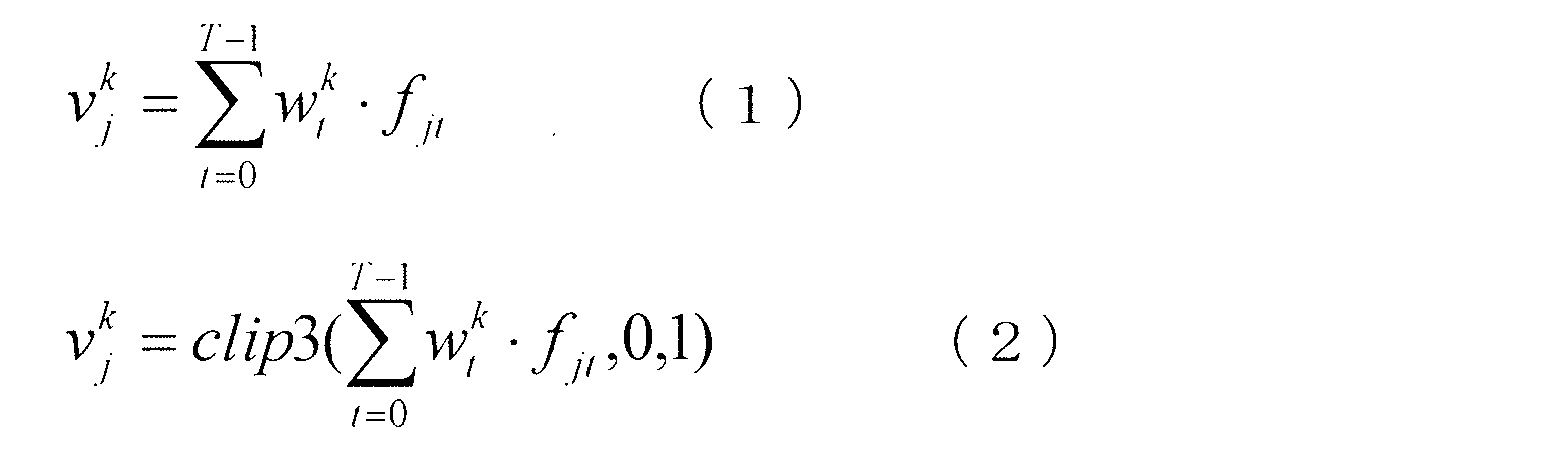
画像に関連する特徴(fjtによって測定される)は、一般線形モデルにおいて予め規定され得る。一般に、最小/最大/平均値は、画像のルマ範囲およびその画像の明るさレベルの良好な指標を提供する。さらに、オプションまたは代替として、ルマ強度値およびクロマ値についての画素値の分布が一般線形モデルにおける画像に関連する特徴において表され得る。 The features associated with the image (measured by f jt ) can be pre-defined in the general linear model. In general, the minimum / maximum / average value provides a good indicator of the Luma range of an image and the brightness level of that image. In addition, as an option or alternative, the distribution of pixel values for Luma intensity and chroma values can be represented in the image-related features of the general linear model.
例えば、一般線形モデルにおける画像に関連する特徴は、以下の3つのカテゴリにおける3セットの特徴を含み得る。 For example, image-related features in a general linear model may include three sets of features in the following three categories:
特徴セット1は、SDR画像の統計値をキャプチャするために使用され、j番目のSDRフレームについての平均ルマ値(
![]()
![]()
![]()
![]()
![]()
![]()
いくつかの実施形態において、特徴セット1は、以下のように、上記の特徴の他に、より高次の特徴を含み得る。

なお、より広く言うと、逆方向再構成関数のより高次の非線形特性を考慮するために、より高次の特徴を使用し得る。したがって、より高次の特徴を使用して訓練されたモデルは、そうでない場合よりも正確になり得る。しかし、より高次の特徴を訓練されたモデルに含めることはまた、訓練プロセス(160)および推定プロセス(162)における計算複雑性を増加させる。より重要なことは、より高次の特徴を訓練されたモデルに含ませると、例えば一般線形モデルの係数を最適化する一方で、特異点(singularity)および/または過剰適合(overfitting)を非常に導入しがちである。いくつかの実施形態において、1つ以上の交差検証方法を実施して、これらの課題または問題を回避または改善し得る。訓練データベースにおける一部のSDR-EDR画像対を任意の過剰適合問題を検出および解決するための検証データとして取っておいてもよい。さらに、オプションまたは代替として、例えば、(1)MLモデルの重みに基づいて予測された予測逆方向再構成関数と、(2)リファレンス逆方向再構成関数(例えば、CDFに基づくマッチングを介して構築される、など)との間の差を最小化するためのコスト関数(またはエラー関数)に、1つ以上の拘束条件または正則化(regularization)項/係数が導入され得る。 More broadly, higher-order features may be used to take into account the higher-order nonlinear properties of the inverse reconstruction function. Therefore, a model trained with higher-order features can be more accurate than it would otherwise be. However, including higher order features in the trained model also increases the computational complexity in the training process (160) and the estimation process (162). More importantly, including higher-order features in the trained model, for example, optimizing the coefficients of a general linear model, while very much singularity and / or overfitting. It tends to be introduced. In some embodiments, one or more cross-validation methods may be implemented to avoid or ameliorate these challenges or problems. Some SDR-EDR image pairs in the training database may be set aside as validation data for detecting and resolving any overfitting problems. In addition, as an option or alternative, for example, (1) a predicted inverse reconstruction function predicted based on the weights of the ML model and (2) a reference inverse reconstruction function (eg, constructed via CDF-based matching). One or more constraints or regularization terms / coefficients may be introduced into the cost function (or error function) to minimize the difference between them.
いくつかの実施形態において、式(2)に示される1次から4次の特徴が特徴セット1に含まれ得る。 In some embodiments, feature set 1 may include primary to quaternary features represented by formula (2).
特徴セット2は、ルマ値の分布をキャプチャするために使用され得、NL階級(bin)ルマヒストグラムにおけるルマ階級を含む。特徴セット3は、クロマ飽和の分布をキャプチャするために使用され得、NC階級クロマヒストグラムを含む。特徴セット2および3における特徴は、以下のようにキャプチャされ得る。 Feature set 2 can be used to capture the distribution of Luma values and includes the Luma class in the NL class (bin) Luma histogram. Feature set 3 can be used to capture the distribution of chroma saturation and includes an NC - class chroma histogram. The features in feature sets 2 and 3 can be captured as follows.
![]()
![]()
![]()
![]()


![]()
![]()
いくつかの実施形態において、NL階級ルマヒストグラムは、全部で8個のルマ階級を含む。したがって、特徴セット2における特徴の総数NLおよび特徴セット3における特徴の総数NCは、以下のように与えられる。
NL=NC=8 (4)
In some embodiments, the N L class Luma histogram contains a total of 8 Luma classes. Therefore, the total number of features N L in the feature set 2 and the total number of features N C in the feature set 3 are given as follows.
N L = NC = 8 (4)
本例において、図1FのMLに基づくプロセスの一般線形モデルにおいて使用される3セットの特徴は、特徴セット1からの4*3=12個の特徴、特徴セット2からの8個の特徴、および特徴セット3からの8個の特徴を含み、SDRフレーム(または画像)から抽出された全部で28個の特徴を生じさせる。 In this example, the three sets of features used in the general linear model of the process based on ML in FIG. 1F are 4 * 3 = 12 features from feature set 1, 8 features from feature set 2, and It contains 8 features from feature set 3 and gives rise to a total of 28 features extracted from the SDR frame (or image).
[係数最適化]
例示として、訓練データベースは、訓練を目的とした全部でF個のSDR-EDR画像対を含む。k番目のサンプル点の重み
![]()
By way of example, the training database contains a total of F SDR-EDR image pairs for training purposes. Weight of kth sample point
![]()
図1Fの訓練プロセス(160)のブロック190(「K点BLUT値を読み出す」と表記する)において、全ての実際のマッピングされたEDRコードワード(または値)は、k番目のサンプル点についてのF個のSDR-EDR画像対におけるF個EDR画像の全てから収集され得る。F個のEDR画像における実際のマッピングされたEDRコードワードは、F個のSDR-EDR画像対におけるそれぞれのSDR-EDR画像対から収集される。それぞれのSDR-EDR画像対から収集された各そのような実際のマッピングされたEDRコードワードは、それぞれのSDR-EDR画像対におけるSDR画像におけるk番目のSDRサンプルコードワードがそれぞれのSDR-EDR画像対におけるEDR画像のEDRコードワードの分布にマッピングされたマッピングEDRコードワードとして決定され得る。 In block 190 (denoted as “reading the K point BLUT value”) of the training process (160) of FIG. 1F, all actual mapped EDR codewords (or values) are F for the kth sample point. It can be collected from all F EDR images in an SDR-EDR image pair. The actual mapped EDR codewords in the F EDR images are collected from each SDR-EDR image pair in the F SDR-EDR image pairs. Each such actual mapped EDR codeword collected from each SDR-EDR image pair is such that the kth SDR sample codeword in the SDR image in each SDR-EDR image pair is the respective SDR-EDR image. It can be determined as a mapping EDR codeword mapped to the distribution of EDR codewords in a pair of EDR images.
例えば、それぞれのSDR-EDR画像対におけるSDR画像におけるSDRコードワードの分布は、SDR画像の実際のSDRコードワードから計算されたSDR CDFによって表され得る。同様に、それぞれのSDR-EDR画像対におけるEDR画像におけるEDRコードワードの分布は、EDR画像の実際のEDRコードワードから計算されたEDR CDFによって表され得る。それぞれのSDR-EDR画像対から収集された実際のマッピングされたEDRコードワードは、EDR CDFの値がk番目のSDRサンプルコードワードでのSDR CDFの値に等しいかまたは一致するEDRコードワードとして決定され得る。 For example, the distribution of SDR codewords in an SDR image in each SDR-EDR image pair can be represented by an SDR CDF calculated from the actual SDR codewords in the SDR image. Similarly, the distribution of EDR codewords in the EDR image in each SDR-EDR image pair can be represented by the EDR CDF calculated from the actual EDR codeword in the EDR image. The actual mapped EDR codeword collected from each SDR-EDR image pair is determined as the EDR codeword whose EDR CDF value is equal to or matches the SDR CDF value in the kth SDR sample codeword. Can be done.
k番目のサンプル点についてのF個のSDR-EDR画像対におけるF個のEDR画像の全てから収集された実際のマッピングされたEDRコードワードは、以下のようにベクトルとして表され得る。

j番目のSDRフレームについて収集された特徴は、以下のようにベクトルとして表され得る。
訓練データベースからのF個のSDR-EDR画像対におけるF個のSDRフレームの全てについての全ての収集された特徴は、以下のようにベクトル(例えば、横(transverse)ベクトルなど)として表され得る。
![]()
![]()
重み(または、一般線形モデルの係数)は、以下のようにベクトル形に配置され得る。

j番目のEDRフレームについての予測または推定された、マッピングされたEDRコードワード(または値)は、一般線形モデルにおいて以下のように与えられ得る。
![]()
![]()
図1Fの訓練プロセス(160)のブロック192(「係数最適化」と表記する)において、F個のSDR-EDR画像対の全てのEDR画像における全ての予測または推定されたEDRコードワード(または値)は、以下のようにベクトルにまとめられる。

式(9)および(10)に基づいて、F個のSDR-EDR画像対の全てのEDR画像における全ての予測または推定されたEDRは、以下の行列形に書き換えられ得る。
![]()
![]()
重みwkの最適化値
![]()

![]()
最適化された重み値
![]()
![]()
![]()
![]()
上記の最適化は、各サンプル点kについて最適化された重み値
![]()
![]()
[BLUTの生成]
推定プロセス(162)において、入力SDR映像(例えば、SDR画像(117)を含む、など)は、訓練されたMLモデル(または、一般線形モデル)によって生成された、最適化された重み値を使用して処理され、入力SDR映像における各フレーム(または画像)についてコンポーザ予測係数が生成される。さらに、オプションまたは代替として、ポストプロセッシングモジュールを推定プロセス(162)において使用して、入力SDR映像のための予測された逆方向再構成関数が平滑性および/または単調な非低減特性を有することを確実にし得る。
[Blood generation]
In the estimation process (162), the input SDR video (eg, including the SDR image (117)) uses optimized weight values generated by the trained ML model (or general linear model). To generate a composer prediction factor for each frame (or image) in the input SDR video. In addition, as an option or alternative, a post-processing module is used in the estimation process (162) to ensure that the predicted inverse reconstruction function for the input SDR video has smoothness and / or monotonous non-reduction properties. Can be certain.
より詳細には、図1FのMLに基づくプロセスの推定プロセス(162)のブロック188において、最適化された重み値
![]()
![]()
![]()
![]()
予測または推定されたEDRコードワード、および予測または推定されたEDRコードワードに対応するSDRコードワードを使用して、逆方向再構成(または予測)プロセスにおいて使用されることになる最適化された逆方向再構成曲線/関数(例えば、パラメータ化曲線/関数、BLUT、近似多項式など)を構築し得る。 Optimized inverse that will be used in the reverse reconstruction (or prediction) process using the predicted or estimated EDR codeword and the SDR codeword corresponding to the predicted or estimated EDR codeword. Directional reconstruction curves / functions (eg, parameterized curves / functions, BLUT, approximate polynomials, etc.) can be constructed.
より詳細には、推定プロセス(162)のブロック188において、新しいSDR画像(例えば、SDR映像を表す1シーケンスのSDR画像に含まれる)のそれぞれについて、まず各そのような新しいSDR画像から特徴が収集される。次いで、各そのような新しいSDR画像について、最適化値
![]()
![]()
K個の予測/推定されたEDRコードワードおよびK個のSDRサンプルコードワードは、一緒になってK個のサンプル点
![]()
![]()
![]()
![]()
![]()
![]()
![]()
![]()
![]()
![]()
![]()
![]()
[単調非低減性]
図2Bおよび図2Cは、いくつかのBLUT例を例示する。図2Bに例示する第1のBLUT例204-1は、単調非低減条件を満たす、補間されたBLUT
![]()
![]()
![]()
[Monotonic non-reduction]
2B and 2C illustrate some BLUT examples. The first BLUT example 204-1 illustrated in FIG. 2B is an interpolated BLUT satisfying the monotonous non-reduction condition.
![]()
![]()
![]()
補間されたBLUT(例えば、図2Cなど)がこの単調非低減条件満たすか否かは、補間されたBLUTが得られる(例えば、上記の補間およびクリッピングを介して)K点BLUTにおいて隣接するサンプル点間の差分値に遡り得る。 Whether or not the interpolated BLUT (eg, FIG. 2C) satisfies this monotonic non-reduction condition is that the interpolated BLUT is obtained (eg, via the above interpolation and clipping) at the adjacent sample points at the K point BLUT. It can be traced back to the difference value between.
例えば、K点BLUT
![]()
![]()
![]()
![]()
![]()
![]()
K点BLUT
![]()
![]()
![]()
![]()
図2Bに例示する第1の補間されたBLUT
![]()
![]()
これに対して、図2Cにおいて例示する第2の補間されたBLUT
![]()
![]()
![]()
![]()
![]()
![]()
![]()
![]()
本明細書に記載される技術を使用して、転写関数(例えば、補間されたBLUT、最終BLUT Bj、EDR画像を予測するために下流のデバイスによって使用されることになる逆方向再構成関数など)が単調非低減条件を満たし、転写関数によってSDRコードワードから予測/推定されるEDRコードワードが、そのSDRコードワードの値が大きくなるにつれても、非低減となることを確実にし得る。単調非低減条件を満たすことは、対応するSDR映像から予測される、構成されたEDR映像の一貫した振る舞いを確実にすることに役立つので、EDR画素強度は、SDR画素強度の増加にともなって低減することはない。 Using the techniques described herein, transfer functions (eg, interpolated BLUT, final BLUT B j , inverse reconstruction functions that will be used by downstream devices to predict EDR images. Etc.) satisfy the monotonous non-reduction condition, and it can be ensured that the EDR codeword predicted / estimated from the SDR codeword by the transcription function becomes non-reduced as the value of the SDR codeword increases. The EDR pixel intensity decreases as the SDR pixel intensity increases, as satisfying the monotonous non-reduction condition helps ensure the consistent behavior of the configured EDR image predicted from the corresponding SDR image. There is nothing to do.
いくつかの実施形態において、単調非低減の最終BLUTを生成するために、単調非低減条件は、一般線形モデルを規定することの一部(例えば、拘束条件など)として、K点BLUTに対して課され得る。 In some embodiments, to generate a monotonous non-reducing final BLUT, the monotonic non-reducing condition is for the K-point BLUT as part of defining a general linear model (eg, constraints). Can be imposed.
追加的に、オプションとして、または代替として、単調非低減の最終BLUTを生成するために、単調非低減条件は、既に構築された、補間された全範囲BLUTに課され得る。例えば、CDFに基づくマッチングを使用することにより、(単調非低減条件を満たしてもよいし、または満たさなくてもよい)補間された全範囲BLUTを、単調非低減条件を満たさないように変更された、補間された全範囲BLUTに再構築する効率的な方法を与え得る。 Additionally, as an option or alternative, to generate a monotonous non-reduced final BLUT, monotonous non-reduced conditions may be imposed on the already constructed, interpolated full range BLUT. For example, by using CDF-based matching, the interpolated full range BLUT (which may or may not meet the monotonous non-reduction condition) is modified to not meet the monotonous non-reduction condition. It can also provide an efficient way to reconstruct the interpolated full range BLUT.
第1のステップは、 SDRヒストグラム(例えば、SDRルマヒストグラムなど)をSDR画像(入力SDR画像)におけるSDRコードワードに基づいて構築し、対応するEDRヒストグラム(例えば、EDRルマヒストグラムなど)を、(単調非低減条件を満たしてもよいし、満たさなくてもよい)補間されたBLUTを使用して予測または推定されるEDRコードワードに基づいて構築することである。より多くのヒストグラム階級を使用すると、CDFに基づくマッチングの正確性がより高くなる。 The first step builds an SDR histogram (eg, SDR Luma histogram, etc.) based on the SDR codeword in the SDR image (input SDR image), and the corresponding EDR histogram (eg, EDR Luma histogram, etc.) (monotonically). The non-reduction condition may or may not be met) to build on the predicted or estimated EDR codeword using the interpolated BLUT. The more histogram classes are used, the more accurate the CDF-based matching will be.
j番目のフレームについての入力SDR画像におけるp番目の画素のルマ正規化値を
![]()
![]()

![]()
![]()
EDRルマヒストグラム(
![]()
![]()
![]()

![]()
![]()
![]()
![]()
![]()

![]()
![]()
各入力SDRコードワードbについてのCDF値を使用して、
![]()
![]()
これにより、{b}→{b´}のSDR-EDRマッピング関数が生成される。このマッピング関数は、単調非低減条件を満たし、j番目のSDR画像からj番目のEDR画像を構成するための
![]()
![]()
さらに、オプションまたは代替として、以下のように平均化フィルタを用いてマッピング関数
![]()

![]()
![]()
![]()
いくつかの実施形態において、式(17)の平滑化されたマッピング関数は、最終BLUT Bjを表し得る。いくつかの実施形態において、最終BLUT Bjは、1セットの多項式(例えば、8区分(piece)2次多項式など)を用いてさらに近似され得る。ピボット(pivot)、傾き、係数、オフセットなどのパラメータは、本明細書に記載されるコンポーザ予測係数とされ得る。 In some embodiments, the smoothed mapping function of equation (17) may represent the final BLUT B j . In some embodiments, the final BLUT B j can be further approximated using a set of polynomials (eg, eight-degree quadratic polynomials, etc.). Parameters such as pivot, slope, coefficient, offset, etc. can be the composer prediction coefficients described herein.
図2Dは、図2Cの補間されたBLUT
![]()
![]()
![]()
![]()
[DMメタデータの推定および生成]
種々の方法およびアルゴリズムのうちの1つ以上を使用し、コンポジションメタデータに少なくとも部分的に基づいて、EDRドメインにおいてDMメタデータを生成するための技術が使用され得る。これらの方法およびアルゴリズムは、EDRドメイン(例えば、DM色空間における、EDR RGB色空間における、など)においてDMメタデータを計算するための元の式を使用すること、EDRドメイン(例えば、コンポジション色空間における、EDR YCbCr色空間における、など)においてDMメタデータを計算するための近似式を使用すること、SDRドメイン(例えば、SDR YCbCr色空間における、など)において計算されたDM関連値をマッピング(例えば、1D-LUT介して、など)することによって、EDRドメインにおいてDMメタデータを生成することなどのいずれかを含み得るが、これらのみに限定されない。
[Estimation and generation of DM metadata]
Techniques for generating DM metadata in the EDR domain can be used using one or more of various methods and algorithms, at least in part based on composition metadata. These methods and algorithms use the original formulas for computing DM metadata in the EDR domain (eg, in the DM color space, in the EDR RGB color space, etc.), the EDR domain (eg, composition color). Use approximations to calculate DM metadata in space, in EDR YCbCr color space, etc.), and map DM-related values calculated in SDR domain (eg, in SDR YCbCr color space, etc.). For example, via 1D-LUT, etc.) may include, but are not limited to, generating DM metadata in the EDR domain.
限定しないが、例示として、コンポーザメタデータおよびSDR画像(117)とともに映像信号に含まれるDMメタデータは、EDR RGB色空間におけるPQ P3ドメインにおいて測定されることになる。なお、種々の実施形態において、DMメタデータは、ここに例示したEDR RGB色空間とは異なるDM色空間において生成または測定され得る。いくつかの実施形態において、EDR RGB色空間は、リファレンスEDRディスプレイのディスプレイ色空間を表し得る。 By way of example, but not limited to, the composer metadata and the DM metadata contained in the video signal along with the SDR image (117) will be measured in the PQ P3 domain in the EDR RGB color space. In various embodiments, the DM metadata can be generated or measured in a DM color space different from the EDR RGB color space exemplified here. In some embodiments, the EDR RGB color space may represent the display color space of the reference EDR display.
入力SDR YCbCr(またはYUV)画像を考慮し、EDR YCbCr(またはYUV)画像が構成/予測を介して生成され得る。いくつかの実施形態において、EDR YCbCr(またはYUV)画像は、EDR RGB色空間におけるDMメタデータを生成するために、生成され、そしてコンポジション色空間であるEDR YCbCr色空間からEDR RGB色空間に変換され得る。 Considering the input SDR YCbCr (or YUV) image, an EDR YCbCr (or YUV) image can be generated via configuration / prediction. In some embodiments, the EDR YCbCr (or YUV) image is generated to generate DM metadata in the EDR RGB color space, and from the composition color space EDR YCbCr color space to the EDR RGB color space. Can be converted.
EDR RGB色空間におけるPQ P3ドメインにおいて測定されることになるDMメタデータは、各EDR画像についての全てのチャネルについての全ての画素値についての最小値(「min」と表記する)、各EDR画像についての全てのチャネルについての全ての画素値についての最大値(「max」と表記する)、各EDR画像についての全てのチャネルについての全ての画素値についての平均値(「avg」と表記する)、各EDR画像についての全てのチャネルについての全ての画素値についての標準偏差値(「std」と表記する)などを含み得るがこれに限定されない。min、max、およびavg値は、L1メタデータと称され得る。std値は、L4メタデータと称され得る。L1およびL4メタデータに少なくとも部分的に基づくディスプレイマネジメント演算の例は、2016年12月22日に出願された米国仮特許出願第62/437,960号に示されており、その内容の全てを、あたかも本明細書中に記載するかのように、本願に援用する。 The DM metadata that will be measured in the PQ P3 domain in the EDR RGB color space is the minimum value (denoted as "min") for all pixel values for all channels for each EDR image and each EDR image. Maximum value for all pixel values for all channels (denoted as "max"), average value for all pixel values for all channels for each EDR image (denoted as "avg") , Standard deviation values (denoted as "std") for all pixel values for all channels for each EDR image, and the like, but are not limited thereto. The min, max, and avg values can be referred to as L1 metadata. The std value may be referred to as L4 metadata. An example of a display management operation based at least in part on L1 and L4 metadata is shown in US Provisional Patent Application No. 62 / 437,960 filed December 22, 2016, all of which is contained in full. , As described herein, incorporated herein by reference.
正規化(したがって、EDRコードワードまたは値は、[0 1)の間にある)後の、j番目のEDR画像におけるp番目の画素についての{R,G,B}チャネルを
![]()

![]()
[YCbCrドメインにおいてYチャネルを使用する推定]
元のEDR RGB式に表されるL1およびL4メタデータを含むがこれらに限定されないEDRドメインにおけるDMメタデータの一部または全ては、実際にはEDR RGB画像を生成せずに、EDR YCbCr色空間におけるY成分の予測されたEDRコードワードなどの、コンポジション色空間における予測されたEDRコードワード(または値)を使用して推定され得る。
[Estimation using Y channel in YCbCr domain]
Some or all of the DM metadata in the EDR domain, including but not limited to L1 and L4 metadata expressed in the original EDR RGB formula, does not actually produce an EDR RGB image and is an EDR YCbCr color space. Can be estimated using the predicted EDR code word (or value) in the composition color space, such as the predicted EDR code word for the Y component in.
j番目のEDR YCbCr画像におけるEDR画素の{Y,Cb,Cr}EDRコードワード(または値)を


Rec.709に準拠する、構成されたEDR画像について、式(19)の右手側(RHS)の3×3行列(「全範囲行列」と表記する)およびベクトルは、それぞれ以下のように与えられる。
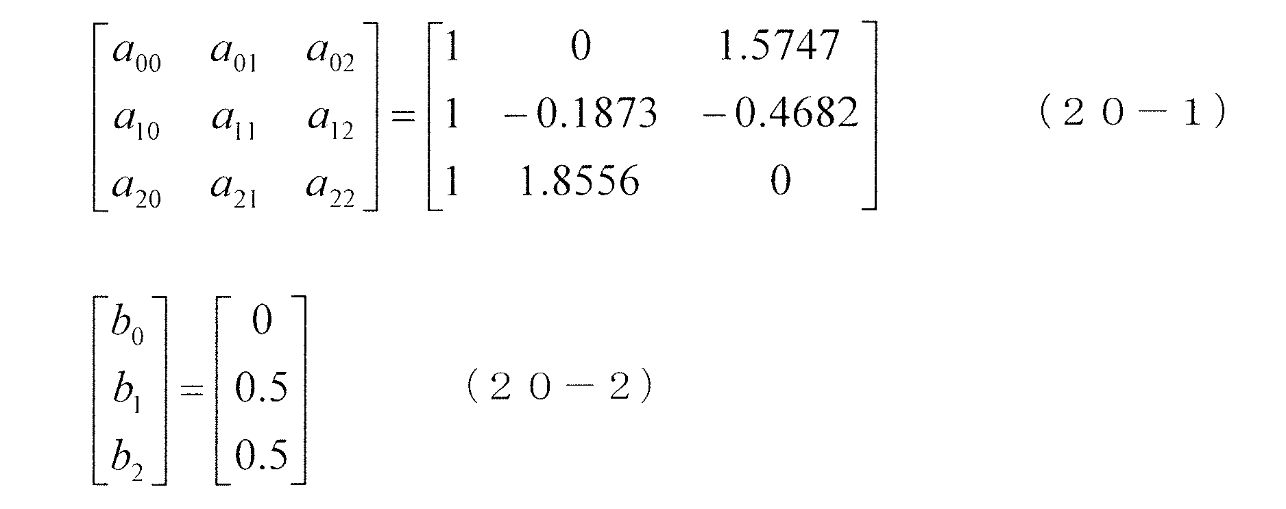
SMPTEに準拠する、構成されたEDR画像について、式(19)の右手側(RHS)の3×3行列(「SMPTE行列」と表記する)およびベクトルは、それぞれ以下のように与えられる。

このように、全範囲行列および対応するベクトルを使用して、以下のように近似関係が成立され得る。

L1メタデータにおけるmin、max、およびavg値は、以下のように推定され得る。

L4メタデータにおける標準偏差値は、以下のように推定され得る。

同様に、SMPTE行列および対応するベクトルを使用して、以下の近似関係が成立され得る。

元のEDR RGB式におけるL1メタデータにおけるmin、max、およびavg値は、以下のようにEDR YCbCrコードワードから推定され得る。

元のEDR RGB式におけるL4メタデータにおける標準偏差値は、以下のようにEDR YCbCrコードワードから推定され得る。

[SDRドメインにおける推定]
上記に例示したように、EDRドメインにおけるDMメタデータは、EDRドメインにおけるEDRコードワードの統計量を含む。リファレンスモード(例えば、図1Bに例示、など)において、EDRコードワードの統計量は、予測演算におけるリファレンスとして機能するリファレンスEDR画像または逆DM(EDR)画像のいずれかにおいてEDRコードワードから収集され得る。非リファレンスモード(例えば、図1Cに例示、など)において、EDRコードワードの統計量は、構成/予測の前にはリファレンスEDR画像および逆DM画像のどちらも存在しない場合があるので、構成/予測されたEDR画像におけるEDRコードワードから収集され得る。
[Estimation in SDR domain]
As exemplified above, DM metadata in the EDR domain includes statistics of EDR codewords in the EDR domain. In reference mode (eg, illustrated in FIG. 1B), EDR codeword statistics can be collected from EDR codeword in either a reference EDR image or an inverse DM (EDR) image that serves as a reference in a predictive operation. .. In non-reference modes (eg, illustrated in FIG. 1C), the EDR codeword statistics may be configured / predicted because neither the reference EDR image nor the inverse DM image may be present prior to the configuration / prediction. It can be collected from the EDR code word in the EDR image.
上記式(18)および(25)に例示される、EDRドメインにおいて統計量測定または収集(例えば、直接に、など)するために、特にDMメタデータの生成に役立てるために、構成/予測されたEDR画像の、一部または全てのEDRコードワードが生成される。このEDR画像構成(または予測)は、なおも著しい計算パワーを消費し得るが、サブサンプリングを採用して、EDRドメインにおいて統計量を計算するためのEDRコードワードの数を減らしてもよい。 Constructed / predicted for statistical measurement or collection (eg, directly, etc.) in the EDR domain, exemplified in the above equations (18) and (25), and particularly to aid in the generation of DM metadata. Some or all EDR codewords of the EDR image are generated. Although this EDR image composition (or prediction) can still consume significant computational power, subsampling may be employed to reduce the number of EDR codewords for calculating statistics in the EDR domain.
いくつかの実施形態において、EDRドメインにおいて統計量を直接的に収集する代わりに、特にDMメタデータを生成するのに役立てるために、EDR画像の構成または予測を一切せずに、既に利用可能なSDRコードワードを用いて、SDRドメインにおいて、まず統計量を収集し得る(例えば、図1DのDMメタデータ生成器(176)によって、など)。逆方向再構成関数/曲線(または、BLUT)が利用可能であるので(例えば、図1Dのコンポーザ予測モジュール(180)からDMメタデータ生成器(176)、など)、EDRドメインにおける統計量は、逆方向再構成関数/曲線(または、BLUT)を用いて、比較的容易にSDRドメインから推定される(例えば、図1DのDMメタデータ生成器(176)によって、など)。 In some embodiments, instead of collecting statistics directly in the EDR domain, it is already available without any configuration or prediction of the EDR image, especially to help generate DM metadata. Statistics can first be collected in the SDR domain using the SDR codeword (eg, by the DM metadata generator (176) in FIG. 1D, etc.). Since the inverse reconstruction function / curve (or BLUT) is available (eg, from the composer prediction module (180) to the DM metadata generator (176), etc. in FIG. 1D), the statistics in the EDR domain are Estimated from the SDR domain relatively easily using the inverse reconstruction function / curve (or BLUT) (eg, by the DM metadata generator (176) in FIG. 1D, etc.).
j番目のSDR画像のp番目のSDR画素の、[0,1)の範囲に正規化され得る、{Y,Cb,Cr}SDRコードワードを
![]()
![]()
j番目のSDR画像に対応するj番目のEDR画像のp番目のEDR画素のルマEDRコードワードは、以下のように上記BLUTに基づいて導出され得る。
![]()
![]()
EDRドメイン(または、j番目のEDR画像)におけるL1メタデータにおけるminおよびmax値は、以下のようにSDRドメイン(または、 j番目のSDR画像)におけるminおよびmax値から推定され得る。

BLUTは、非線形関数であるので、SDRドメインにおけるavg値は、BLUTに基づくシングル値マッピングを介しては、EDRドメインにおけるavg値に一致しない場合がある。この問題は、SDRヒストグラム(例えば、SDRルマヒストグラムなど)およびBLUTを使用することを介して解決され得る。j番目のSDR画像のSDRヒストグラムのb番目の階級を
![]()
![]()
EDRドメイン(または、j番目のEDR画像)におけるL1メタデータにおけるavg値は、以下のようにSDRヒストグラムおよびBLUTから推定され得る。

EDRドメイン におけるL4メタデータにおけるstd値の計算は、BLUTが非線形関数である場合があるので、上記のEDRドメインにおけるL1メタデータにおけるavg値の計算と同じ問題を有する。 The calculation of the std value in the L4 metadata in the EDR domain has the same problem as the calculation of the avg value in the L1 metadata in the EDR domain described above because BLUT may be a non-linear function.
しかし、EDRドメイン(または、j番目のEDR画像)におけるL4メタデータにおけるstd値はまた、以下のようにSDRヒストグラムおよびBLUTから推定され得る。

上記から分かるように、 EDRドメインにおけるDMメタデータは、逆方向再構成関数/曲線(またはthe BLUT)に少なくとも部分的に基づいて、入力SDR信号(またはSDR画像)の統計量測定から、上流の符号化デバイスによって対応するEDR画像を構成することなく、マッピングされ得る。これにより、このSDRドメインにおいて計算された統計量および分布(例えば、ヒストグラムなど)を介してEDRドメインにおけるDMメタデータを導出する方法を使用することによって、著しい計算量を回避し得る。 As can be seen from the above, the DM metadata in the EDR domain is upstream from the statistic measurement of the input SDR signal (or SDR image), at least partially based on the inverse reconstruction function / curve (or the BLUT). It can be mapped without constructing the corresponding EDR image by the encoding device. Thereby, significant computational complexity can be avoided by using the method of deriving DM metadata in the EDR domain via the statistics and distributions calculated in this SDR domain (eg, histograms, etc.).
なお、
![]()
![]()
![]()
![]()
[ビット深度および空間寸法の再フォーマット化]
多くの場合、入力SDR映像信号は、1080pまたは2160pとは異なるフレームサイズを有する8ビットYUV映像信号である。しかし、いくつかの映像ディスプレイアプリケーションは、10ビットYUV映像信号におけるSDR画像データおよび画像関連メタデータを受信およびプロセッシングするように構成され得る。
[Reformatting bit depth and spatial dimensions]
In most cases, the input SDR video signal is an 8-bit YUV video signal with a frame size different from 1080p or 2160p. However, some video display applications may be configured to receive and process SDR image data and image-related metadata in a 10-bit YUV video signal.
図1Gは、入力ビット深度(例えば、8ビットなど)および入力フレーム(空間)寸法(例えば、1080pまたは2160p以外)を出力ビット深度(例えば、10ビットなど)および出力フレーム(空間)寸法(例えば、1080pまたは2160pなど)に再フォーマット化するためのエンコーダ側アーキテクチャを例示する。図1Gのエンコーダ側コーデックアーキテクチャは、上流の映像エンコーダ(例えば、図1Aの符号化ブロック(120)など)における1つ以上のコンピューティングプロセッサを用いて実装され得る。 FIG. 1G shows input bit depth (eg, 8 bits, etc.) and input frame (spatial) dimensions (other than 1080p or 2160p) as output bit depth (eg, 10 bits, etc.) and output frame (spatial) dimensions (eg,). Illustrate an encoder-side architecture for reformatting to 1080p or 2160p, etc.). The encoder-side codec architecture of FIG. 1G can be implemented using one or more computing processors in an upstream video encoder (eg, such as the coding block (120) of FIG. 1A).
エンコーダ側アーキテクチャを使用して、ビット深度(niと表記する)および入力フレームサイズの入力SDR映像信号を、出力ビット深度(noと表記する)および出力フレームサイズの出力SDR映像信号に再フォーマットし得る。出力SDR映像信号は、当該分野において既に利用されている所定のディスプレイアプリケーションまたはシステムと既に互換であるか、または比較的容易に互換にされ得る映像信号フォーマットの信号である。 Reformat the input SDR video signal with bit depth ( denoted as n i ) and input frame size to the output SDR video signal with output bit depth (denoted as no) and output frame size using the encoder-side architecture. Can be. The output SDR video signal is a signal in a video signal format that is already compatible with, or can be relatively easily compatible with, a given display application or system already in use in the art.
限定しないが、例示として、図1Gのエンコーダアーキテクチャは、フレームサイズが(Wi×Hi)であるSDR画像(117)を用いて符号化されたniビットのSDR映像信号を受信するように構成される。コンポーザ予測モジュール(180)は、静的または動的非リファレンスモードで動作し、コンポーザ予測係数を決定/生成する。予測係数は、リファレンス(または、予測ターゲット)として、 EDR画像を一切使用せず、かつ逆DM画像(例えば、図1Bの逆DMモジュール(172)によって生成されるものなど)を一切使用せずに生成され得る。 By way of example, but not limited to, the encoder architecture of FIG. 1G is such that it receives an n i -bit SDR video signal encoded with an SDR image (117) having a frame size of (Wi x Hi ) . It is composed. The composer prediction module (180) operates in static or dynamic non-reference mode to determine / generate composer prediction coefficients. The prediction factor uses no EDR image as a reference (or prediction target) and no reverse DM image (eg, one generated by the reverse DM module (172) in FIG. 1B). Can be generated.
αRを以下のコードワードスケーリングファクタ186(例えば、乗算子など)とする。
αR=1<<(n0-ni) (28)
Let α R be the following codeword scaling factor 186 (eg, multiplier).
α R = 1 << ( n 0 -ni) (28)
SDR画像(117)における入力ビット深度の各入力SDRルマコードワード(またはSDRルマ画素値)は、αRと乗算されて、スケーリングされたSDR画像(117-1)における出力ビット深度の対応のSDRルマコードワードを生成する。 Each input SDR Luma codeword (or SDR Luma pixel value) of the input bit depth in the SDR image (117) is multiplied by α R and the corresponding SDR of the output bit depth in the scaled SDR image (117-1). Generate a Luma code word.
コンポーザ予測モジュール(180)によって決定/生成された予測係数は、RPU(178)に与えられ、入力SDR画像(117)(例えば、入力SDR画像(117)におけるコードワードなど)をαRを用いてスケーリングすることによって生成されたスケーリング化SDR画像(117-1)を用いて符号化ビットストリーム(122)内に多重化または含められ得る。 The prediction coefficient determined / generated by the composer prediction module (180) is given to the RPU (178) and the input SDR image (117) (eg, the codeword in the input SDR image (117)) is used with α R. The scaling SDR image (117-1) generated by scaling can be multiplexed or included in the coded bitstream (122).
受信機(例えば、図1Eのデコーダなど)は、スケーリング化SDR画像(117-1)および予測係数を受信した後、予測係数を使用して、SDR画像(117-1)から予測されたEDR画像を生成し得る。 The receiver (eg, the decoder of FIG. 1E) receives the scaled SDR image (117-1) and the prediction factor and then uses the prediction factor to predict the EDR image from the SDR image (117-1). Can be generated.
図1Gに例示されるエンコーダ側において、SDR画像(117-1)および予測係数は、非リファレンスモードで動作するコンポーザ構成モジュール(184)に与えられ、EDR画像のEDR画素値の一部または全てを構成する。 On the encoder side illustrated in FIG. 1G, the SDR image (117-1) and prediction coefficients are given to the composer configuration module (184) operating in non-reference mode to capture some or all of the EDR pixel values in the EDR image. Configure.
DMメタデータ生成器(176)は、DM色空間におけるEDR画素値の一部または全てを受信し、そしてこれらのEDR画素値を使用して、DMメタデータを推定、計算、または生成する。次いで、DMメタデータは、DMメタデータ生成器(176)によってRPU(178)に与えられ、スケーリング化SDR画像(117-1)およびthe コンポーザメタデータを用いて符号化ビットストリーム(122)内に多重化または含められ得る。 The DM metadata generator (176) receives some or all of the EDR pixel values in the DM color space and uses these EDR pixel values to estimate, calculate, or generate DM metadata. The DM metadata is then fed to the RPU (178) by the DM metadata generator (176) and into the coded bitstream (122) using the scaled SDR image (117-1) and the composer metadata. Can be multiplexed or included.
入力SDR画像におけるSDR画素の数および出力SDR画像におけるSDR画素の数は、それぞれ以下のように与えられる。
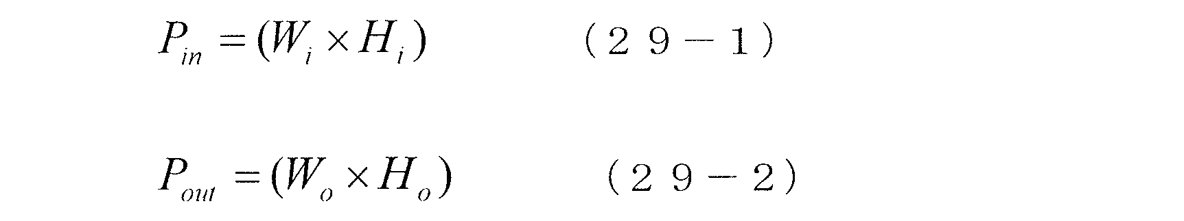
スケーリングされたj番目のSDR画像における入力SDRコードワードを使用して、j番目のSDR画像に対応するj番目のEDR画像におけるEDRコードワードを予測または構成し得る。
![]()
![]()
PRをj番目のSDR画像におけるPin個の入力画素を補完して、j番目のEDR画像におけるPout個の出力画素を生成するためにパディングされた画素の数とする。したがって、
PR=Pout-Pin (30)
である。
P is the number of pixels padded to complement the P in input pixels in the jth SDR image to generate P out output pixels in the jth EDR image. therefore,
PR = P out -P in (30)
Is.
![]()
![]()
![]()
![]()
![]()
![]()
![]()
![]()
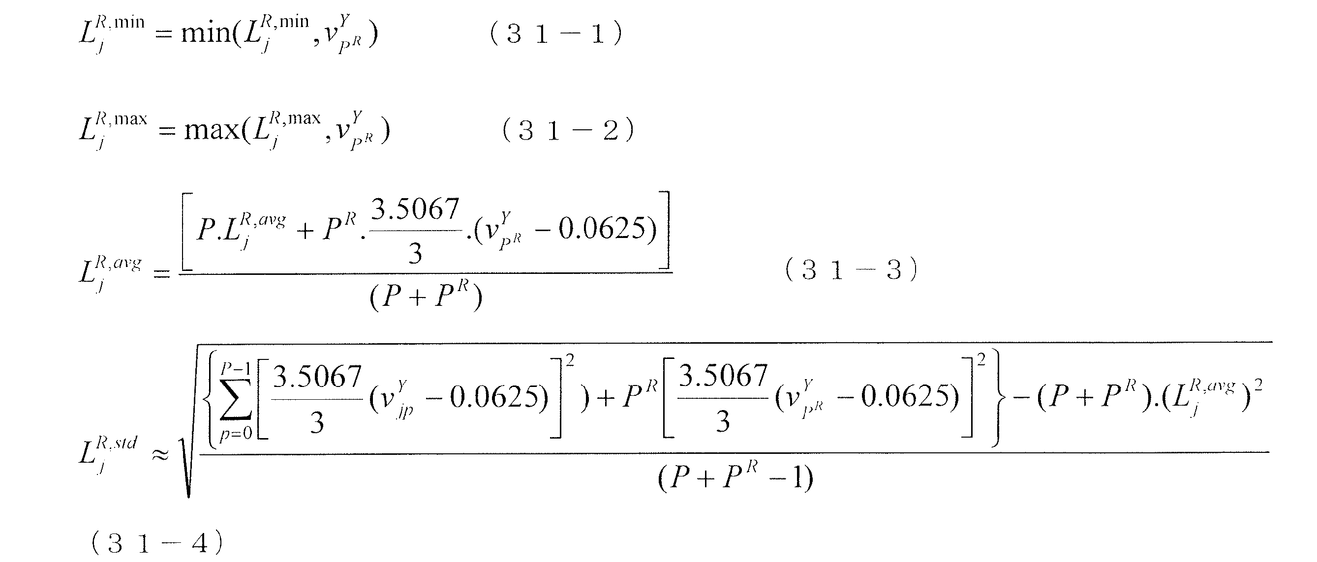
![]()
![]()
[シーンに基づくメタデータ計算]
L1 DMメタデータは、映像エンコーダ(例えば、図1Aの符号化ブロック(120)など)によって、画像関連メタデータの一部として受信機(例えば、EDRディスプレイとともに動作する映像復号化デバイスなど)に送信され、受信機によって構成されることになるEDR画像の最小、最大、および平均値を提供し得る。L4 DMメタデータは、映像エンコーダによって、画像関連メタデータの一部として受信機に送信され、フレーム平均値およびフレーム標準偏差値を提供し得る。
[Scene-based metadata calculation]
The L1 DM metadata is transmitted by a video encoder (eg, the coding block (120) of FIG. 1A, etc.) to a receiver (eg, a video decoding device that works with an EDR display) as part of the image-related metadata. It may provide the minimum, maximum, and average values of the EDR image that will be configured by the receiver. The L4 DM metadata may be transmitted by the video encoder to the receiver as part of the image-related metadata to provide frame mean and frame standard deviation values.
さらに、オプションまたは代替として、最小、最大および平均輝度値を含むが、これらに限定されないシーンレベルのL1およびL4 DMメタデータが映像エンコーダによって生成され、受信機に送信され得る。j番目のEDRについての左および右シーン境界を
![]()

![]()
シーンの最大輝度値(max_PQと表記する)は、以下のように計算され得る。

シーンの中点輝度値(avg_PQと表記する)は、以下のように計算され得る。

いくつかの実施形態において、EDR画像(例えば、現在のEDR画像、j番目のEDR画像など)のフィルタリングされた平均および標準偏差値を含むが、これらに限定されない、フィルタリングされたL1およびL4 DMメタデータが映像エンコーダによって生成され、受信機に送信され得る。 In some embodiments, the filtered L1 and L4 DM metas include, but are not limited to, filtered mean and standard deviation values of EDR images (eg, current EDR image, j-th EDR image, etc.). Data can be generated by the video encoder and transmitted to the receiver.
![]()
![]()
![]()
![]()
![]()
![]()
![]()
![]()
j番目のEDR画像のフィルタリングされた平均および標準偏差値は、以下のように決定され得る。

上記から分かるように、映像エンコーダによって生成されたL1/L4メタデータの一部は、シーンカット情報に依存(例えば、非常に依存など)し得る。いくつかの実施形態において、比較的正確なシーンカット情報が例えばXMLファイルの形態で利用可能である。しかし、いくつかの他の実施形態において、シーンカット情報は、例えば映像エンコーダ、または映像エンコーダと併せて動作するデバイスによって画像コンテンツから自動的に検出される必要があり得る。 As can be seen from the above, some of the L1 / L4 metadata generated by the video encoder can depend on the scene cut information (eg, very dependent). In some embodiments, relatively accurate scene cut information is available, for example, in the form of an XML file. However, in some other embodiments, the scene cut information may need to be automatically detected from the image content by, for example, a video encoder, or a device operating in conjunction with the video encoder.
[誤シーンカット検出に対する感度]
自動シーンカット検出(例えば、人間が入力を全くまたはほとんどせずに、自動画像コンテンツ分析に基づく、など)は、映画などのいくつかの映像コンテンツに対しては良く機能し得る。しかし、誤ったまたは逃したシーンカット検出が特に映画以外の映像コンテンツにおいて生じ得る場合がある。
[Sensitivity to erroneous scene cut detection]
Automatic scene cut detection (eg, based on automatic image content analysis with little or no human input) can work well for some video content such as movies. However, false or missed scene cut detection can occur, especially in non-movie video content.
例えば、誤シーンカットは、映像に焼き付けられたキャプションがある場合に、検出され得る。焼き付けられたキャプションは、1つのシーンフレーム中の数フレームにおいて、または1つのシーンにおいてもしくは複数のシーンにわたって、オン・オフし得る。1つのシーンは、1つの焼き付けられたキャプションまたは複数の焼き付けられたキャプションを有し得る。焼き付けられたキャプションのこれらの異なる振る舞いが存在すると、クリーンな自動シーンカット検出が困難となり得る。 For example, false scene cuts can be detected if the video has captions burned into it. The burned captions can be turned on and off in a few frames in a scene frame, in a scene, or across multiple scenes. One scene can have one burned caption or multiple burned captions. The presence of these different behaviors of burned captions can make clean automatic scene cut detection difficult.
L1メタデータにおけるシーンレベル最小および最大輝度値などのDMメタデータにおけるシーンレベル値は、シーンカットに影響を受けやすい。新しい焼き付けられたキャプション(例えば、白色の明るい画素を含む、など)が現れると、シーンレベルおよび画像レベル最大輝度値が上昇し、他方、焼き付けられたキャプションが消えると、シーンレベルおよび画像レベル最大輝度値がとなる。 Scene level values in DM metadata such as scene level minimum and maximum brightness values in L1 metadata are susceptible to scene cuts. When new burned captions appear (for example, containing bright white pixels), the scene level and image level maximum brightness values increase, while when the burned captions disappear, the scene level and image level maximum brightness values increase. The value is.
画像内の画素の総数に比べて、焼き付けられたキャプションが含む画素が比較的少ない場合、シーンレベルおよび画像レベル平均輝度値は、ほとんど変化しない場合がある。 If the burned caption contains relatively few pixels compared to the total number of pixels in the image, the scene level and image level average brightness values may remain almost unchanged.
いくつかの実施形態において、最小および最大輝度値(例えば、一部または全てシーンについての、など)は、以下のようにシーケンス全体についての最小および最大輝度値などの1シーケンスの画像(例えば、複数のシーンを含む、など)における大域値として設定され得る。

いくつかの実施形態において、平均輝度値は、シーンカットのうちのいずれかが検出有りであるか、または検出無しであるかにかかわらず、各シーンから計算される平均輝度値に設定され得る。 In some embodiments, the average luminance value may be set to the average luminance value calculated from each scene, whether any of the scene cuts are detected or not.
いくつかの演算の場合において、1つの真のシーンが複数の(誤った)シーンであると、誤って検出され得る。これらの複数の誤ったシーンは、1つの真のシーンの異なる誤ったシーンにおける画像から計算される、異なる平均輝度値を有する。ディスプレイの照明制御は、これらの平均輝度値に少なくとも部分的に基づいて、照明レベルを調節し得る。これにより、真の1つのシーンにおける異なる誤ったシーンを介して、照明レベルの調節によって生じる閃光(flashing)が見られ得る。 In the case of some operations, one true scene can be erroneously detected as multiple (wrong) scenes. These plurality of erroneous scenes have different average luminance values calculated from images in different erroneous scenes of one true scene. The lighting control of the display may adjust the lighting level based at least in part on these average brightness values. This allows you to see the flashing caused by the adjustment of the lighting level through different false scenes in one true scene.
この問題に対処するために、平均輝度値の推定に基づくスライディングウィンドウを採用し得る。シーンカット情報(例えば、EDR画像がシーンカット画像であるか否かを示すバイナリインディケータ(binary indicator)など)によって境界づけられたスライディングウィンドウを使用して、各EDR画像についての平均輝度値が計算され得る。 To address this issue, a sliding window based on an estimated average luminance value may be employed. An average luminance value for each EDR image is calculated using a sliding window bounded by scene cut information (eg, a binary indicator indicating whether the EDR image is a scene cut image). obtain.
j番目のEDR画像についての(スライディング)ウィンドウに基づく平均輝度値を
![]()
![]()
![]()
![]()
![]()
![]()
スライディング(または平均)ウィンドウの左および右境界を
![]()

![]()
ここで、j番目のEDRについての平均輝度値に基づくスライディングウィンドウは、以下のように決定され得る。
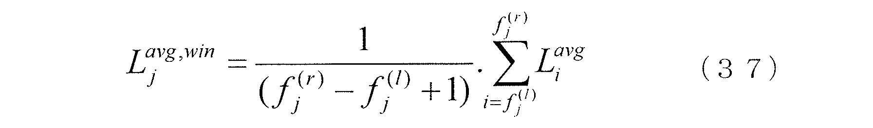
図3は、1シーケンスの画像にわたる平均輝度値のプロット例を例示する。第1のプロット302は、フレームレベルの平均輝度値を表す。各フレームレベルの平均輝度値は、その1シーケンスの画像における対応の個々の画像に基づいて計算される。第2のプロット304は、シーンレベル平均輝度値を表す。各シーンレベル平均輝度値は、その1シーケンスの画像における対応のシーンについて、正しいかもしれないし、正しくないかもしれないシーンカット検出に基づいて計算される。第3のプロット306は、スライディングウィンドウ平均輝度値を表す。各スライディングウィンドウ平均輝度値は、個々の画像について、シーンカット検出および画像レベル平均輝度値の両方に基づいて計算される。
FIG. 3 illustrates an example of plotting the average luminance value over one sequence of images. The
画像レベル平均輝度値が大きく変化し得ることが見て取れる。シーンレベル平均輝度値は、検出されたシーンカットに基づいて、段階的に変化する。誤ったおよび/または逃したシーンカットが生じる場合、これらの平均輝度値を使用して照明制御を決定すると閃光が生じ得る。スライディングウィンドウに基づく平均輝度値は、局所的なスライディングウィンドウ平均に基づいて、比較的平滑な輝度値曲線を生成する。局所的なスライディングウィンドウ平均は、間違って検出されたシーンカットが生じても可視閃光を回避または低減する。 It can be seen that the image level average luminance value can change significantly. The scene level average brightness value changes stepwise based on the detected scene cut. In the event of false and / or missed scene cuts, flashing can occur when determining lighting control using these average brightness values. The average luminance value based on the sliding window produces a relatively smooth luminance value curve based on the local sliding window average. Local sliding window averaging avoids or reduces visible flashes in the event of erroneously detected scene cuts.
いくつかの実施形態において、本明細書に記載される逆方向再構成関数は、クリッピングまたはトリムパス(trim pass)を行わずに、および/またはSDR画像を構成されたEDR画像にマッピングする際に画素値の所定のコードワード領域において完全な情報損失を起こさずに、生成される。これにより、SDR画像において表される画像の詳細は、本明細書に記載される技術において、構成されたEDR画像において保存される。 In some embodiments, the reverse reconstruction functions described herein are pixels without clipping or trim pass and / or when mapping an SDR image to a configured EDR image. Generated without complete information loss in a given codeword area of the value. Thereby, the details of the image represented in the SDR image are preserved in the configured EDR image in the techniques described herein.
いくつかの実施形態において、本明細書に記載される逆方向再構成関数を使用して、SDR画像が表されるソース色空間と、構成されたEDR画像が表されるターゲット色空間との任意の組み合わせをサポートし得る。ソース色空間および/またはターゲット色空間の例は、YCbCr色空間、IPT色空間、RGB色空間、Rec.2020色空間、Rec.709色空間などのいずれをも含み得るが、必ずしもそれらのみに限定されない。 In some embodiments, the inverse reconstruction function described herein is used to optionally represent a source color space in which an SDR image is represented and a target color space in which a constructed EDR image is represented. Can support combinations of. Examples of the source color space and / or the target color space include the YCbCr color space, the IPT color space, the RGB color space, Rec. 2020 color space, Rec. It may include, but is not limited to, any of the 709 color spaces and the like.
本明細書に記載されるSDR-EDRマッピング(例えば、逆方向再構成曲線/関数、行列に基づくマッピングなど)は、CDF基づくマッピング、MMR基づくマッピング、CDF・MMR基づくマッピングなどであり得るが、これらに必ずしも限定されない。いくつかの実施形態において、SDR-EDRマッピングは、入力色空間の1、2、3またはそれ以上の次元におけるSDRコードワードに適用され、出力色空間の1、2、3またはそれ以上の次元におけるEDRコードワードを生成し得る。 The SDR-EDR mappings described herein (eg, inverse reconstruction curves / functions, matrix-based mappings, etc.) can be CDF-based mappings, MMR-based mappings, CDF-MMR-based mappings, and the like. Not necessarily limited to. In some embodiments, SDR-EDR mapping is applied to SDR codewords in 1, 2, 3 or more dimensions of the input color space and in 1, 2, 3 or more dimensions of the output color space. It can generate EDR codewords.
第1の例において、逆方向再構成曲線/関数は、入力SDR色空間のルマ成分(またはチャネル)におけるSDRコードワードを出力EDR色空間のルマ成分(またはチャネル)におけるEDRコードワードにマッピングするために適用され得る。 In the first example, the inverse reconstruction curve / function maps the SDR codeword in the Luma component (or channel) of the input SDR color space to the EDR codeword in the Luma component (or channel) of the output EDR color space. Can be applied to.
第2の例において、MMRに基づくマッピングは、入力SDR色空間の1つ以上のルマおよびクロマ成分(またはチャネル)におけるSDRコードワードを出力EDR色空間の1つ以上のクロマ成分(チャネル)におけるEDRコードワードにマッピングするために適用され得る。MMRに基づくマッピングの例は、上記の米国仮特許出願第62/404,307号に示されている。MMRに基づくマッピングのさらなる例は 、2013年10月8日に出願された米国特許出願第14/110,694号に示されており、その内容の全てを、あたかも本明細書中に記載するかのように、本願に援用する。 In a second example, the MMR-based mapping outputs SDR codewords in one or more Luma and chroma components (or channels) in the input SDR color space EDR in one or more chroma components (channels) in the EDR color space. Can be applied to map to codewords. An example of mapping based on MMR is shown in US Provisional Patent Application No. 62 / 404,307 above. A further example of MMR-based mapping is set forth in U.S. Patent Application No. 14 / 110,694, filed October 8, 2013, as if all of its contents were described herein. Incorporated into this application.
例示のみを目的として、本明細書の記載ようにコンポジションメタデータおよび/またはDMメタデータが入力映像信号におけるSDR画像について生成されることにより、下流のデバイスがSDR画像からEDR画像を構成/予測し、EDR画像をターゲットディスプレイ用のディスプレイ画像にマッピングできるようにし得ることを説明した。なお、しかし、種々の実施形態において、入力映像信号における入力ダイナミックレンジおよび/または入力色域の画像は、Rec.709に規定されるSDR画像などのSDR画像でもよいし、そうでなくてもよい。例えば、いくつかの実施形態において、Rec.709 SDRの入力ダイナミックレンジ以外の入力ダイナミックレンジ(例えば、4000ニト、1000ニトなど)のハイブリッドログガンマ(HLG)画像は、本明細書に記載されるように、入力映像信号から復号化され得る。コンポジションメタデータおよび/またはDMメタデータは、HLG画像について生成され、下流のデバイスがHLG画像からEDR画像を構成/予測し、EDR画像をターゲットディスプレイ用のディスプレイ画像にマッピングできるようにし得る。 For purposes of illustration only, composition metadata and / or DM metadata is generated for the SDR image in the input video signal as described herein so that the downstream device composes / predicts the EDR image from the SDR image. It was explained that the EDR image can be mapped to the display image for the target display. However, in various embodiments, the image of the input dynamic range and / or the input color gamut in the input video signal is obtained by Rec. It may or may not be an SDR image such as the SDR image specified in 709. For example, in some embodiments, Rec. A hybrid log gamma (HLG) image with an input dynamic range other than the input dynamic range of the 709 SDR (eg, 4000 nits, 1000 nits, etc.) can be decoded from the input video signal as described herein. Composition metadata and / or DM metadata may be generated for the HLG image to allow downstream devices to construct / predict the EDR image from the HLG image and map the EDR image to a display image for the target display.
[プロセスフロー例]
図4Aは、本発明のある実施形態によるプロセスフロー例を例示する。いくつかの実施形態において、1つ以上のコンピューティングデバイスまたは構成要素(例えば、符号化デバイス/モジュール、トランスコーディングデバイス/モジュール、復号化デバイス/モジュール、逆トーンマッピングデバイス/モジュール、トーンマッピングデバイス/モジュール、メディアデバイス/モジュールなど)は、このプロセスフローを行い得る。ブロック402において、画像プロセッシングデバイス(例えば、符号化ブロック(120)など)がスタンダードダイナミックレンジ(SDR)画像を受信する。
[Process flow example]
FIG. 4A illustrates an example of a process flow according to an embodiment of the present invention. In some embodiments, one or more computing devices or components (eg, coding device / module, transcoding device / module, decoding device / module, reverse tone mapping device / module, tone mapping device / module). , Media devices / modules, etc.) can perform this process flow. At block 402, an image processing device (eg, a coded block (120), etc.) receives a standard dynamic range (SDR) image.
ブロック404において、画像プロセッシングデバイスは、SDR画像をエンハンストダイナミックレンジ(EDR)画像にマッピングするためのコンポーザメタデータを生成する。コンポーザメタデータは、訓練データベースにおける複数のSDR-EDR画像対から生成された逆方向再構成マッピングを特定する。複数のSDR-EDR画像対は、上記のSDR画像を含まない複数のSDR画像と、その複数のSDR画像に対応する複数のEDR画像とを含む。ある実施形態において、逆方向再構成マッピングは、複数のSDR-EDR画像対を用いて予測係数を訓練することによって得られた、最適化された予測係数値から生成される。 At block 404, the image processing device generates composer metadata for mapping the SDR image to an enhanced dynamic range (EDR) image. The composer metadata identifies the reverse reconstruction mapping generated from multiple SDR-EDR image pairs in the training database. The plurality of SDR-EDR image pairs include a plurality of SDR images that do not include the above-mentioned SDR image, and a plurality of EDR images corresponding to the plurality of SDR images. In certain embodiments, the reverse reconstruction mapping is generated from optimized prediction factor values obtained by training the prediction factors with multiple SDR-EDR image pairs.
ブロック406において、画像プロセッシングデバイスは、出力SDR映像信号において、SDR画像およびコンポーザメタデータを符号化する。 At block 406, the image processing device encodes the SDR image and composer metadata in the output SDR video signal.
ブロック408において、画像プロセッシングデバイスは、出力SDR映像信号の受信機とともに動作するEDRディスプレイにEDRディスプレイ画像を描画させる。EDRディスプレイ画像は、コンポーザメタデータに基づいてSDR画像から構成された構成EDR画像から導出される。 At block 408, the image processing device causes the EDR display, which operates with the receiver of the output SDR video signal, to draw the EDR display image. The EDR display image is derived from a configured EDR image composed of SDR images based on composer metadata.
ある実施形態において、SDR画像は、出力SDR映像信号において符号化されている1シーケンスのSDR画像である。 In certain embodiments, the SDR image is a sequence of SDR images encoded in the output SDR video signal.
ある実施形態において、コンポーザメタデータは、構成されたEDR画像が生成されるコンポジション色空間、構成されたEDR画像用のリファレンスEDRディスプレイによってサポートされるピーク輝度値などのうちの1つ以上に基づいて選択された逆方向再構成関数を特定する。 In certain embodiments, the composer metadata is based on one or more of the composition color spaces in which the configured EDR image is generated, the peak brightness values supported by the reference EDR display for the configured EDR image, and the like. Identify the selected inverse reconstruction function.
ある実施形態において、画像プロセッシングデバイスは、SDR画像から複数の画像関連特徴を抽出すること、その複数の画像関連特徴、および複数のSDR-EDR画像対を使用して生成された複数の最適化された重み値に基づいて逆方向再構成マッピングを特定する1セットのパラメータを生成することなどを行うようにさらに構成される。 In certain embodiments, the image processing device extracts a plurality of image-related features from an SDR image, the plurality of image-related features, and a plurality of optimizations generated using the plurality of SDR-EDR image pairs. It is further configured to generate a set of parameters that specify the reverse reconstruction mapping based on the weighted values.
ある実施形態において、複数の最適化された重み値は、複数のSDR-EDR画像対を使用して、一般線形モデルにおいて生成される。 In certain embodiments, multiple optimized weight values are generated in a general linear model using multiple SDR-EDR image pairs.
ある実施形態において、複数の画像関連特徴は、SDR画像におけるSDRルマコードワードから計算された1セットのルマ統計値に関連する特徴、SDR画像におけるSDRルマコードワードの分布に関連する特徴、SDR画像におけるSDRルマコードワードの分布に対応するクロマ値に関連する特徴などのうちの1つ以上を含む。 In certain embodiments, the plurality of image-related features are features related to a set of Luma statistics calculated from SDR Luma codewords in an SDR image, features related to the distribution of SDR Luma codewords in an SDR image, SDR images. Includes one or more of the features associated with the chroma value corresponding to the distribution of SDR Luma codewords in.
ある実施形態において、画像プロセッシングデバイスは、SDRコードワード空間にわたって分布する1セットのSDRコードワードについての1セットの推定されたEDRコードワードを生成すること、その1セットの推定されたEDRコードワードに基づいて、補間された逆方向再構成マッピングを生成すること、その補間された逆方向再構成マッピングを、出力SDR映像信号において符号化され、単調非低減条件を満たす逆方向再構成関数に変更することなどを行うようにさらに構成される。 In certain embodiments, the image processing device produces a set of estimated EDR codewords for a set of SDR codewords distributed across the SDR codeword space, to that set of estimated EDR codewords. Based on it, it produces an interpolated reverse reconstruction mapping, which is coded in the output SDR video signal and changed to a reverse reconstruction function that satisfies the monotonous non-reduction condition. Further configured to do things and so on.
ある実施形態において、画像プロセッシングデバイスは、移動SDRコードワードウィンドウにわたって逆方向再構成関数を平滑化することを行うようにさらに構成される。 In certain embodiments, the image processing device is further configured to perform reverse reconstruction function smoothing across a moving SDR codeword window.
ある実施形態において、逆方向再構成マッピングは、逆方向再構成曲線、逆方向再構成関数、パラメータ化マッピング関数、逆方向ルックアップテーブル(BLUT)、1セットの近似多項式区分、行列に基づくマッピングなどのうちの1つを表す。 In certain embodiments, the reverse reconstruction mapping includes a reverse reconstruction curve, a reverse reconstruction function, a parameterized mapping function, a reverse lookup table (BLUT), a set of approximate polynomial divisions, a matrix-based mapping, and the like. Represents one of them.
ある実施形態において、出力SDR映像信号は、ディスプレイマネジメント(DM)メタデータを用いてさらに符号化される。ディスプレイマネジメント(DM)メタデータは、受信機によって、リファレンスEDRディスプレイ用に最適化された構成EDR画像に対してDM演算を行うために使用され、EDRディスプレイ用に最適化されたEDRディスプレイ画像を生成することになる。 In certain embodiments, the output SDR video signal is further encoded using display management (DM) metadata. Display management (DM) metadata is used by the receiver to perform DM operations on the configured EDR image optimized for the reference EDR display and generate an EDR display image optimized for the EDR display. Will be done.
ある実施形態において、上記方法は、映像エンコーダによって行われる。DMメタデータは、DM色空間について、コンポジション色空間において構成されたEDRコードワードを使用する近似に基づいて、映像エンコーダによって生成される。 In certain embodiments, the method is performed by a video encoder. The DM metadata is generated by the video encoder based on an approximation using the EDR codeword constructed in the composition color space for the DM color space.
ある実施形態において、DMメタデータは、DM色空間について、そのDM色空間について生成されたEDRコードワードに基づいて、映像エンコーダによって生成される。 In certain embodiments, DM metadata is generated by a video encoder for a DM color space based on the EDR codeword generated for that DM color space.
ある実施形態において、DMメタデータは、DM色空間について、SDR画像におけるSDRコードワードの分布から導出されたマッピング統計値に基づいて、映像エンコーダによって生成される。 In certain embodiments, DM metadata is generated by the video encoder for the DM color space based on mapping statistics derived from the distribution of SDR codewords in the SDR image.
ある実施形態において、DMメタデータは、フレームレベルのDMメタデータ、シーンレベルのDMメタデータ、マルチシーンレベルのDMメタデータ、手動シーンカット情報に少なくとも部分的に基づいて生成されるDMメタデータ、自動的に検出されたシーンカット情報に少なくとも部分的に基づいて生成されるDMメタデータ、スライディングウィンドウを用いて生成された、フィルタリングされたDMメタデータなどのうちの1つ以上を含む。 In certain embodiments, the DM metadata is frame-level DM metadata, scene-level DM metadata, multi-scene-level DM metadata, DM metadata generated at least in part based on manual scene cut information, It contains at least one or more of DM metadata generated based on at least partially based on automatically detected scene cut information, filtered DM metadata generated using a sliding window, and the like.
ある実施形態において、SDR画像、構成されたEDR画像、またはEDRディスプレイ画像のうちの少なくとも1つは、IPT PQ(ICtCp)色空間、YCbCr色空間、RGB色空間、Rec.2020色空間、Rec.709色空間、拡張ダイナミックレンジ(EDR)色空間、ガンマ/HLG/PQ色空間、スタンダードダイナミックレンジ(SDR)色空間などのうちの1つにおいて表される。 In certain embodiments, at least one of the SDR image, the configured EDR image, or the EDR display image is an IPT PQ (ICtCp) color space, a YCbCr color space, an RGB color space, Rec. 2020 color space, Rec. It is represented in one of a 709 color space, an extended dynamic range (EDR) color space, a gamma / HLG / PQ color space, a standard dynamic range (SDR) color space, and the like.
IPT-PQ色空間は、ディスプレイマネジメントアプリケーションのために、2014年2月13日に出願されたPCT出願シリアル番号PCT/US2014/016304において最初に公開された。“Development and testing of a color space (ipt) with improved hue uniformity”,by F.Ebner and M.D.Fairchild,in Proc.6th Color Imaging Conference:Color Science,Systems,and Applications,IS&T,Scottsdale,Arizona,Nov.1998,pp.8-13(以下、Ebner論文と称す)(その開示内容を全て本願で援用する)に記載されるIPTは、人間の視覚系における錐体間の色差のモデルである。この意味において、IPTは、YCbCrまたはCIE-Lab色空間と同様であるが、いくつかの科学研究において、これらの空間よりも人間の視覚プロセッシングをより良く模倣することが示されてきた。CIE-Labと同様に、IPTは、所定のリファレンス輝度に対して正規化された空間である。ある実施形態において、その正規化は、ターゲットディスプレイの最大輝度(例えば、5,000ニト)に基づく。 The IPT-PQ color space was first published for the Display Management application at the PCT application serial number PCT / US2014 / 016304 filed February 13, 2014. “Development and testing of a color space (ipt) with improved weeniformity”, by F. et al. Ebner and M. D. Fairchild, in Proc. 6th Color Imaging Conference: Color Science, Systems, and Applications, IS & T, Scottsdale, Arizona, Nov. 1998, pp. The IPT described in 8-13 (hereinafter referred to as the Ebner paper) (all of which are incorporated herein by reference) is a model of color difference between cones in the human visual system. In this sense, IPT is similar to the YCbCr or CIE-Lab color spaces, but some scientific studies have shown that they better mimic human visual processing than these spaces. Like the CIE-Lab, the IPT is a space normalized to a given reference brightness. In certain embodiments, the normalization is based on the maximum brightness of the target display (eg, 5,000 nits).
本明細書において、「PQ」という用語は、知覚的量子化を指す。人間の視覚系は、光レベルの増大に対して非常に非線形的に反応する。人間が刺激を見る能力は、その刺激の輝度、その刺激の大きさ、その刺激を構成する空間周波数、および、その刺激を見ている特定の時点までに目が適応した輝度レベルに影響される。好適な実施形態において、知覚的量子化子関数は、線形入力グレイレベルを、人間の視覚系におけるコントラスト感度閾値によりマッチした出力グレイレベルにマッピングする。PQマッピング関数の例が、PCT出願シリアル番号PCT/US2012/068212に記載されている。また、PQ非線形系リファレンス転写関数がRec.ITU-RBT.2100-1(06/2017)、「Image parameter values for high dynamic range television for use in production and international programme exchange」に記載されている。これを本願に援用する。 As used herein, the term "PQ" refers to perceptual quantization. The human visual system reacts very non-linearly to increasing light levels. The ability of humans to see a stimulus is influenced by the brightness of the stimulus, the magnitude of the stimulus, the spatial frequencies that make up the stimulus, and the level of brightness that the eye has adapted to the point in time when the stimulus is being viewed. .. In a preferred embodiment, the perceptual quantizer function maps a linear input gray level to an output gray level matched by a contrast sensitivity threshold in the human visual system. An example of the PQ mapping function is described in the PCT application serial number PCT / US2012 / 068212. In addition, the PQ nonlinear system reference transfer function is Rec. ITU-RBT. 21001 (06/2017), "Image parameter values for high dynamic range television for use in product and international program exchange". This is incorporated in this application.
ある実施形態において、SDR画像のビット深度は、8、9、10+ビットなどのうちの1つである。 In certain embodiments, the bit depth of the SDR image is one of 8, 9, 10+ bits and the like.
ある実施形態において、SDR画像は、出力SDR映像信号を同じビット深度の入力SDR映像信号において受信される。 In certain embodiments, the SDR image receives an output SDR video signal at an input SDR video signal of the same bit depth.
ある実施形態において、SDR画像は、出力SDR映像信号とは異なるビット深度の入力SDR映像信号において受信される。この出力SDR映像信号は、ビット深度がスケーリングされたバージョンのSDR画像を含む。 In certain embodiments, the SDR image is received in an input SDR video signal with a bit depth different from the output SDR video signal. This output SDR video signal contains a bit depth scaled version of the SDR image.
ある実施形態において、SDR画像は、映像プロフェッショナルの芸術的な意図に基づいて生成される。 In certain embodiments, the SDR image is generated based on the artistic intent of a video professional.
ある実施形態において、画像プロセッシングデバイスは、SDR画像から抽出された複数の特徴、および複数のSDR-EDR画像対に基づいて訓練された複数の最適化された予測係数に基づいて、それぞれSDRサンプルコードワードを、マッピングされたEDRサンプルコードワードにマッピングする複数のサンプル点マッピングを生成すること、複数のサンプル点マッピングに基づいて、利用可能なSDRコードワードの全範囲にわたって補間された逆方向再構成マッピングを生成すること、利用可能なSDRコードワードの全範囲における各利用可能なSDRコードワードを中心としたスライディングウィンドウを使用して、平均フィルタリングを補間された逆方向再構成マッピングに適用することによって、補間された逆方向再構成マッピングから逆方向再構成マッピングを生成することを行うようにさらに構成される。 In certain embodiments, the image processing device is based on a plurality of features extracted from the SDR image and a plurality of optimized prediction coefficients trained on the basis of a plurality of SDR-EDR image pairs, respectively, with SDR sample code. Generate multiple sample point mappings that map words to mapped EDR sample codewords, reverse reconstruction mapping interpolated over the entire range of available SDR codewords based on multiple sample point mappings. By applying average filtering to interpolated reverse reconstruction mapping using a sliding window centered on each available SDR codeword in the full range of available SDR codewords. It is further configured to generate a reverse reconstruction mapping from the interpolated reverse reconstruction mapping.
ある実施形態において、フィルタリングされたDMメタデータは、スライディングウィンドウに基づいて平滑化フィルタによって平滑化された平均シーンに基づく輝度値を含む。スライディングウィンドウは、自動的に検出されたシーンカット情報において示されるシーンカットにわたって移動する。 In certain embodiments, the filtered DM metadata includes a luminance value based on an average scene smoothed by a smoothing filter based on a sliding window. The sliding window moves over the scene cuts indicated in the automatically detected scene cut information.
図4Bは、本発明のある実施形態によるプロセスフロー例を示す。いくつかの実施形態において、1つ以上のコンピューティングデバイスまたは構成要素(例えば、符号化デバイス/モジュール、トランスコーディングデバイス/モジュール、復号化デバイス/モジュール、逆トーンマッピングデバイス/モジュール、トーンマッピングデバイス/モジュール、メディアデバイス/モジュールなど)がこのプロセスフローを行い得る。ブロック422において、画像プロセッシングデバイス(例えば、符号化ブロック(120)など)がSDR画像およびコンポーザメタデータを用いて符号化されたスタンダードダイナミックレンジ(SDR)映像信号を受信する。 FIG. 4B shows an example of a process flow according to an embodiment of the present invention. In some embodiments, one or more computing devices or components (eg, coding device / module, transcoding device / module, decoding device / module, reverse tone mapping device / module, tone mapping device / module). , Media devices / modules, etc.) can perform this process flow. At block 422, an image processing device (eg, a coding block (120), etc.) receives a standard dynamic range (SDR) video signal encoded using the SDR image and composer metadata.
ブロック424において、画像プロセッシングデバイスは、コンポーザメタデータを使用して、SDR画像を、構成されたエンハンストダイナミックレンジ(EDR)画像にマッピングする。コンポーザメタデータは、訓練データベースにおける複数のSDR-EDR画像対から映像エンコーダによって生成された逆方向再構成マッピングを特定する。複数のSDR-EDR画像対は、上記のSDR画像を含まない複数のSDR画像と、その複数のSDR画像に対応する複数のEDR画像とを含む。 At block 424, the image processing device uses composer metadata to map the SDR image to the configured enhanced dynamic range (EDR) image. The composer metadata identifies the reverse reconstruction mapping generated by the video encoder from multiple SDR-EDR image pairs in the training database. The plurality of SDR-EDR image pairs include a plurality of SDR images that do not include the above-mentioned SDR image, and a plurality of EDR images corresponding to the plurality of SDR images.
ブロック426において、画像プロセッシングデバイスは、SDR映像信号の受信機とともに動作するEDRディスプレイにEDRディスプレイ画像を描画させる。EDRディスプレイ画像は、コンポーザメタデータに基づいてSDR画像から構成された構成EDR画像から導出される。 At block 426, the image processing device causes the EDR display, which operates with the receiver of the SDR video signal, to draw the EDR display image. The EDR display image is derived from a configured EDR image composed of SDR images based on composer metadata.
ある実施形態において、コンポーザメタデータは、SDR画像とは別の画像メタデータとしてSDR映像信号において搬送される。 In certain embodiments, the composer metadata is conveyed in the SDR video signal as image metadata separate from the SDR image.
ある実施形態において、画像プロセッシングデバイスは、構成されたEDR画像に対して色空間変換を行うようにさらに構成される。 In certain embodiments, the image processing device is further configured to perform color space conversion on the configured EDR image.
ある実施形態において、画像プロセッシングデバイスは、SDR映像信号からディスプレイマネジメント(DM)メタデータを抽出すること、構成されたEDR画像からEDRディスプレイ画像を生成することの一部として、構成されたEDR画像に対してDM演算を適用することなどを行うようにさらに構成される。 In certain embodiments, the image processing device is configured on an EDR image as part of extracting display management (DM) metadata from the SDR video signal and generating an EDR display image from the configured EDR image. On the other hand, it is further configured to apply a DM operation or the like.
図4Cは、本発明のある実施形態によるプロセスフロー例を例示する。いくつかの実施形態において、1つ以上のコンピューティングデバイスまたは構成要素(例えば、符号化デバイス/モジュール、トランスコーディングデバイス/モジュール、復号化デバイス/モジュール、逆トーンマッピングデバイス/モジュール、トーンマッピングデバイス/モジュール、メディアデバイス/モジュールなど)がこのプロセスフローを行い得る。ブロック442において、画像プロセッシングデバイス(例えば、符号化ブロック(120)など)がハイブリッドログガンマ(HLG)画像を受信する。 FIG. 4C illustrates an example of a process flow according to an embodiment of the present invention. In some embodiments, one or more computing devices or components (eg, coding device / module, transcoding device / module, decoding device / module, reverse tone mapping device / module, tone mapping device / module). , Media devices / modules, etc.) can perform this process flow. At block 442, an image processing device (eg, a coding block (120), etc.) receives a hybrid log gamma (HLG) image.
ブロック444において、画像プロセッシングデバイスは、HLG画像をエンハンストダイナミックレンジ(EDR)画像にマッピングするためのコンポーザメタデータを生成する。コンポーザメタデータは、訓練データベースにおける複数のHLG-EDR画像対から生成された逆方向再構成マッピングを特定する。複数のHLG-EDR画像対は、上記のHLG画像を含まない複数のHLG画像と、その複数のHLG画像に対応する複数のEDR画像とを含む。ある実施形態において、逆方向再構成マッピングは、複数のHLG-EDR画像対を用いて予測係数を訓練することによって得られた、最適化された予測係数値から生成される。 At block 444, the image processing device generates composer metadata for mapping the HLG image to the enhanced dynamic range (EDR) image. The composer metadata identifies the reverse reconstruction mapping generated from multiple HLG-EDR image pairs in the training database. The plurality of HLG-EDR image pairs include a plurality of HLG images that do not include the above-mentioned HLG image, and a plurality of EDR images corresponding to the plurality of HLG images. In certain embodiments, the reverse reconstruction mapping is generated from optimized prediction factor values obtained by training the prediction factors with multiple HLG-EDR image pairs.
ブロック446において、画像プロセッシングデバイスは、出力HLG映像信号において、HLG画像およびコンポーザメタデータを符号化する。 At block 446, the image processing device encodes the HLG image and composer metadata in the output HLG video signal.
ブロック448において、画像プロセッシングデバイスは、出力HLG映像信号の受信機とともに動作するEDRディスプレイにEDRディスプレイ画像を描画させる。EDRディスプレイ画像は、コンポーザメタデータに基づいてHLG画像から構成された構成EDR画像から導出される。 At block 448, the image processing device causes the EDR display, which operates with the receiver of the output HLG video signal, to draw the EDR display image. The EDR display image is derived from a configured EDR image composed of HLG images based on composer metadata.
ある実施形態において、画像プロセッシングデバイスは、HLG画像から抽出された複数の特徴、および複数のHLG-EDR画像対に基づいて訓練された複数の最適化された予測係数に基づいて、それぞれHLGサンプルコードワードを、マッピングされたEDRサンプルコードワードにマッピングする複数のサンプル点マッピングを生成すること、複数のサンプル点マッピングに基づいて、利用可能なHLGコードワードの全範囲にわたって補間された逆方向再構成マッピングを生成すること、利用可能なHLGコードワードの全範囲における各利用可能なHLGコードワードを中心としたスライディングウィンドウを使用して、平均フィルタリングを補間された逆方向再構成マッピングに適用することによって、補間された逆方向再構成マッピングから逆方向再構成マッピングを生成することなどを行うようにさらに構成される。 In certain embodiments, the image processing device is an HLG sample code based on a plurality of features extracted from the HLG image and a plurality of optimized prediction coefficients trained based on a plurality of HLG-EDR image pairs. Generating multiple sample point mappings that map a word to a mapped EDR sample codeword, a reverse reconstruction mapping interpolated over the entire range of available HLG codewords based on multiple sample point mappings. By applying average filtering to the interpolated reverse reconstruction mapping using a sliding window centered around each available HLG codeword in the full range of available HLG codewords. It is further configured to generate a reverse reconstruction mapping from the interpolated reverse reconstruction mapping.
図4Dは、本発明のある実施形態によるプロセスフロー例を示す。いくつかの実施形態において、1つ以上のコンピューティングデバイスまたは構成要素(例えば、符号化デバイス/モジュール、トランスコーディングデバイス/モジュール、復号化デバイス/モジュール、逆トーンマッピングデバイス/モジュール、トーンマッピングデバイス/モジュール、メディアデバイス/モジュールなど)がこのプロセスフローを行い得る。ブロック462において、画像プロセッシングデバイス(例えば、符号化ブロック(120)など)がHLG画像およびコンポーザメタデータを用いて符号化されたハイブリッドログガンマ(HLG)映像信号を受信する。 FIG. 4D shows an example of a process flow according to an embodiment of the present invention. In some embodiments, one or more computing devices or components (eg, coding device / module, transcoding device / module, decoding device / module, reverse tone mapping device / module, tone mapping device / module). , Media devices / modules, etc.) can perform this process flow. At block 462, an image processing device (eg, a coding block (120), etc.) receives a hybrid log gamma (HLG) video signal encoded using the HLG image and composer metadata.
ブロック464において、画像プロセッシングデバイスは、コンポーザメタデータを使用して、HLG画像を、構成されたエンハンストダイナミックレンジ(EDR)画像にマッピングする。コンポーザメタデータは、訓練データベースにおける複数のHLG-EDR画像対から映像エンコーダによって生成された逆方向再構成マッピングを特定する。複数のHLG-EDR画像対は、上記のHLG画像を含まない複数のHLG画像と、その複数のHLG画像に対応する複数のEDR画像とを含む。 At block 464, the image processing device uses composer metadata to map the HLG image to the configured enhanced dynamic range (EDR) image. The composer metadata identifies the reverse reconstruction mapping generated by the video encoder from multiple HLG-EDR image pairs in the training database. The plurality of HLG-EDR image pairs include a plurality of HLG images that do not include the above-mentioned HLG image, and a plurality of EDR images corresponding to the plurality of HLG images.
ブロック466において、画像プロセッシングデバイスは、HLG映像信号の受信機とともに動作するEDRディスプレイにEDRディスプレイ画像を描画させる。EDRディスプレイ画像は、コンポーザメタデータに基づいてHLG画像から構成された構成EDR画像から導出される。 At block 466, the image processing device causes the EDR display, which operates with the receiver of the HLG video signal, to draw the EDR display image. The EDR display image is derived from a configured EDR image composed of HLG images based on composer metadata.
ある実施形態において、ディスプレイデバイス、モバイルデバイス、セットトップボックス、マルチメディアデバイスなどのあるコンピューティングデバイスは、上記方法のいずれかを行うように構成される。ある実施形態において、ある装置は、プロセッサを含み、上記方法のいずれかを行うように構成される。ある実施形態において、ある非一時的なコンピュータ読み取り可能な記憶媒体は、ソフトウェア命令を記憶する。ソフトウェア命令は、1つ以上のプロセッサによって実行される際に、上記方法のいずれかを行わせる。 In certain embodiments, certain computing devices, such as display devices, mobile devices, set-top boxes, multimedia devices, etc., are configured to perform any of the above methods. In certain embodiments, the device comprises a processor and is configured to perform any of the above methods. In certain embodiments, some non-temporary computer-readable storage medium stores software instructions. Software instructions cause one of the above methods to be performed when executed by one or more processors.
ある実施形態において、あるコンピューティングデバイスは、1つ以上のプロセッサおよび1セットの命令を含む1つ以上の記憶媒体を備える。1セットの命令は、1つ以上のプロセッサによって実行される際に、上記方法のいずれかを行わせる。 In certain embodiments, a computing device comprises one or more processors and one or more storage media containing a set of instructions. A set of instructions causes any of the above methods to be performed when executed by one or more processors.
なお、別々の実施形態を本明細書において記載するが、本明細書に記載の実施形態および/または部分的な実施形態の任意の組み合わせが更なる実施形態を形成し得る。 Although separate embodiments are described herein, any combination of embodiments and / or partial embodiments described herein may form further embodiments.
[コンピュータシステムの実装例]
本発明の実施形態は、コンピュータシステム、電子回路およびコンポーネントで構成されたシステム、マイクロコントローラ、フィールドプログラマブルゲートアレイ(FPG
A)または他のコンフィギュラブルまたはプログラマブルロジックデバイス(PLD)、離散時間またはデジタル信号プロセッサ(DSP)、特定用途向けIC(ASIC)などの集積回路(IC)デバイス、および/または、このようなシステム、デバイスまたはコンポーネントを1つ以上含む装置、を用いて実施し得る。このコンピュータおよび/またはICは、本明細書に記載のエンハンストダイナミックレンジを有する画像の適応型知覚的量子化に関する命令を行い、制御し、または実行し得る。このコンピュータおよび/またはICは、本明細書に記載の適応型知覚的量子化プロセスに関する様々なパラメータまたは値のいずれを演算してもよい。画像およびビデオ実施形態は、ハードウェア、ソフトウェア、ファームウェア、および、その様々な組み合わせで実施され得る。
[Computer system implementation example]
Embodiments of the present invention include a computer system, a system composed of electronic circuits and components, a microcontroller, and a field programmable gate array (FPG).
A) or other configurable or programmable logic devices (PLDs), discrete-time or digital signal processors (DSPs), integrated circuit (IC) devices such as application-specific ICs (ASICs), and / or such systems. , Devices or devices containing one or more components. The computer and / or IC may give, control, or perform commands for adaptive perceptual quantization of images with enhanced dynamic range as described herein. The computer and / or IC may compute any of the various parameters or values associated with the adaptive perceptual quantization process described herein. Image and video embodiments may be implemented in hardware, software, firmware, and various combinations thereof.
本発明の特定の態様は、本発明の方法をプロセッサに行わせるためのソフトウェア命令を実行するコンピュータプロセッサを含む。例えば、ディスプレイ、エンコーダ、セットトップボックス、トランスコーダなどの中の1つ以上のプロセッサは、そのプロセッサがアクセス可能なプログラムメモリ内にあるソフトウェア命令を実行することによって、上記のHDR画像の適応型知覚的量子化に関する方法を実装し得る。本発明は、プログラム製品形態で提供されてもよい。このプログラム製品は、データプロセッサによって実行された時に本発明の方法をデータプロセッサに実行させるための命令を含む1セットの、コンピュータ読み取り可能な信号を格納する任意の非一時的媒体を含み得る。本発明によるプログラム製品は、様々な形態をとり得る。例えば、このプログラム製品は、フロッピーディスク、ハードディスクドライブを含む磁気データ記憶媒体、CD ROM、DVDを含む光学データ記憶媒体、ROM、フラッシュRAMなどを含む電子データ記憶媒体、などの物理的媒体を含み得る。このプログラム製品上のコンピュータ可読信号は、任意に、圧縮または暗号化されていてもよい。 A particular aspect of the invention includes a computer processor that executes software instructions to cause the processor to perform the methods of the invention. For example, one or more processors in a display, encoder, set-top box, transcoder, etc. may perform adaptive perception of the above HDR image by executing software instructions that are in program memory accessible to that processor. A method for target quantization can be implemented. The present invention may be provided in the form of a program product. The program product may include any non-temporary medium containing a set of computer-readable signals containing instructions for causing the data processor to perform the method of the invention when executed by the data processor. The program product according to the present invention can take various forms. For example, the program product may include physical media such as floppy disks, magnetic data storage media including hard disk drives, optical data storage media including CD ROMs, DVDs, electronic data storage media including ROMs, flash RAMs and the like. .. The computer-readable signal on this program product may optionally be compressed or encrypted.
上記においてあるコンポーネント(例えば、ソフトウェアモジュール、プロセッサ、アセンブリ、デバイス、回路など)に言及している場合、そのコンポーネントへの言及(「手段」への言及を含む)は、そうでないと明記されている場合を除いて、当該コンポーネントの機能を果たす(例えば、機能的に均等である)あらゆるコンポーネント(上記した本発明の例示の実施形態に出てくる機能を果たす開示構造に対して構造的に均等ではないコンポーネントも含む)を、当該コンポーネントの均等物として、含むものと解釈されるべきである。 When a component is mentioned above (eg, a software module, processor, assembly, device, circuit, etc.), the reference to that component (including the reference to "means") is specified otherwise. Except as is the case, any component that performs the function of the component (eg, is functionally equal) is structurally uniform with respect to the disclosed structure that performs the function shown in the exemplary embodiments of the invention described above. (Including non-components) should be construed as including as an equivalent of the component.
一実施形態によると、本明細書に記載の技術は、1つ以上の専用コンピューティングデバイスによって実装される。専用コンピューティングデバイスは、上記技術を行うようにハードワイヤードであってもよいし、または上記技術を行うように永続的にプログラムされた1つ以上の特定用途向け集積回路(ASIC)またはフィールド・プログラマブル・ゲート・アレイ(FPGA)などのデジタル電子デバイスを含んでもよし、またはファームウェア、メモリ、他の記憶体、またはそれらの組み合わせにおけるプログラム命令にしたがって上記技術を行うようにプログラムされた、1つ以上の汎用ハードウェアプロセッサを含んでもよい。また、そのような専用コンピューティングデバイスは、カスタムハードワイヤードロジック、ASIC、またはFPGAをカスタムプログラミングと組み合わせて上記技術を達成し得る。専用コンピューティングデバイスは、デスクトップコンピュータシステム、ポータブルコンピュータシステム、携帯デバイス、ネットワーキングデバイス、またはハードワイヤードおよび/もしくはプログラムロジックを含んで上記技術を実装する任意の他のデバイスであり得る。 According to one embodiment, the techniques described herein are implemented by one or more dedicated computing devices. The dedicated computing device may be hard-wired to perform the above techniques, or one or more application-specific integrated circuits (ASICs) or field programmables that are permanently programmed to perform the above techniques. One or more digital electronic devices such as gate arrays (FPGAs) or programmed to perform the above techniques according to program instructions in firmware, memory, other storage units, or combinations thereof. It may include a general purpose hardware processor. Also, such dedicated computing devices may achieve the above techniques by combining custom hardwired logic, ASICs, or FPGAs with custom programming. The dedicated computing device can be a desktop computer system, a portable computer system, a portable device, a networking device, or any other device that implements the above techniques, including hardwired and / or program logic.
例えば、図5は、本発明のある実施形態が実装され得るコンピュータシステム500を例示するブロック図である。コンピュータシステム500は、バス502または情報を送受信するための他の通信機構と、バス502に接続された、情報を処理するためのハードウェアプロセッサ504とを含む。ハードウェアプロセッサ504は、例えば、汎用マイクロプロセッサであり得る。
For example, FIG. 5 is a block diagram illustrating a
また、コンピュータシステム500は、バス502に接続された、情報およびプロセッサ504によって実行されることになる命令を記憶するためのランダムアクセスメモリ(RAM)または他のダイナミック記憶デバイスなどのメインメモリ506を含む。また、メインメモリ506は、プロセッサ504によって実行されることになる命令の実行中の一時的変数または他の中間情報を記憶するために使用され得る。そのような命令は、プロセッサ504がアクセス可能な非一時的な記憶媒体に記憶される場合は、コンピュータシステム500を、命令において特定される動作を行うようにカスタマイズされた専用マシンにする。
The
コンピュータシステム500は、バス502に接続された、静的情報およびプロセッサ504のための命令を記憶するための読み取り専用メモリ(ROM)508または他の静的記憶デバイスをさらに含む。情報および命令を記憶するために、磁気ディスクまたは光学ディスクなどの記憶デバイス510が提供され、バス502に接続される。
The
コンピュータシステム500は、情報をコンピュータユーザに対して表示するための液晶ディスプレイなどのディスプレイ512にバス502を介して接続され得る。プロセッサ504に情報およびコマンド選択を送受信するために、英数字キーまたは他のキーを含む入力デバイス514がバス502に接続される。プロセッサ504に方向情報およびコマンド選択を送受信するための、およびディスプレイ512上のカーソル移動を制御するための他の種類のユーザ入力デバイスは、マウス、トラックボール、またはカーソル方向キーなどのカーソル制御516である。この入力デバイスは、典型的には2つの軸(第1の軸(例えば、x)および第2の軸(例えば、y))における2つの自由度を有する。これにより、そのデバイスは、平面において位置を特定できる。
The
コンピュータシステム500は、コンピュータシステムと組み合わされてコンピュータシステム500を専用マシンにするか、またはプログラムする、ハードワイヤードロジック、1つ以上のASICまたはFPGA、ファームウェアおよび/またはプログラムロジックを使用して、上記技術を実装し得る。一実施形態によると、本明細書に記載される技術は、メインメモリ506に含まれる1つ以上のシーケンスの1つ以上の命令をプロセッサ504が実行することに応答して、コンピュータシステム500によって行われる。そのような命令は、記憶デバイス510などの別の記憶媒体からメインメモリ506に読み込まれ得る。メインメモリ506に含まれる命令シーケンスを実行することによって、プロセッサ504は、本明細書に記載のプロセスステップを行う。別の実施形態において、ハードワイヤードな回路をソフトウェア命令の代わりに、またはそれに組み合わせて使用し得る。
The
本明細書で使用する「記憶媒体」という用語は、マシンを特定のやり方で動作させるデータおよび/または命令を記憶する任意の非一時的媒体を指す。そのような記憶媒体は、不揮発性媒体および/または揮発性媒体を含み得る。非揮発性媒体は、例えば、記憶デバイス510などの光学または磁気ディスクを含む。揮発性媒体は、メインメモリ506などのダイナミックメモリを含む。記憶媒体の一般的な形態は、例えば、フロッピーディスク、フレキシブルディスク、ハードディスク、ソリッドステートドライブ、磁気テープ、または任意の他の磁気データ記憶媒体、CD-ROM、任意の他の光学データ記憶媒体、穴のパターンを有する任意の物理媒体、RAM、PROM、およびEPROM、FLASH-EPROM、NVRAM、任意の他のメモリチップまたはカートリッジを含む。
As used herein, the term "storage medium" refers to any non-temporary medium that stores data and / or instructions that make a machine operate in a particular way. Such storage media may include non-volatile media and / or volatile media. Non-volatile media include, for example, optical or magnetic disks such as
記憶媒体は、伝送媒体とは異なるが、それと併せて使用され得る。伝送媒体は、情報を記憶媒体間で転送することに関与する。例えば、伝送媒体は、同軸ケーブル、銅ワイヤ、および光ファイバを含み、バス502を備えるワイヤを含む。また、伝送媒体は、電波データ通信および赤外データ通信中に生成される音波または光波などの音波または光波の形態をとり得る。
The storage medium is different from the transmission medium but can be used in conjunction with it. Transmission media are involved in transferring information between storage media. For example, the transmission medium includes coaxial cables, copper wires, and optical fibers, including wires comprising a
種々の形態の媒体が1つ以上のシーケンスの1つ以上の命令を実行のためのプロセッサ504に搬送することに関与し得る。例えば、命令は、最初は遠隔のコンピュータの磁気ディスクまたはソリッドステートドライブ上に担持され得る。遠隔コンピュータは、命令をそのダイナミックメモリにロードしたり、命令をモデムを使用して電話回線を介して送信し得る。コンピュータシステム500に対してローカルなモデムは、電話回線上でデータを受信し、赤外送信機を使用してデータを赤外信号に変換し得る。赤外検出器が赤外信号において搬送されるデータを受信し得る。そして、適切な回路がデータをバス502上に配置し得る。バス502は、データをメインメモリ506に搬送する。プロセッサ504は、メインメモリ506から命令を取り込んで、実行する。メインメモリ506によって受信された命令は、プロセッサ504による実行の前または後のいずれかに、必要に応じて記憶デバイス510上に記憶され得る。
Various forms of media may be involved in transporting one or more instructions in one or more sequences to
また、コンピュータシステム500は、バス502に接続された通信インタフェース518を含む。通信インタフェース518は、ローカルネットワーク522に接続されたネットワークリンク520に接続する双方向データ通信を提供する。例えば、通信インタフェース518は、サービス総合デジタル網(ISDN)カード、ケーブルモデム、衛星モデム、またはデータ通信接続を対応する種類の電話回線に与えるためのモデムであり得る。別の例として、通信インタフェース518は、データ通信接続を互換性のあるLANに与えるためのローカルエリア ネットワーク(LAN)カードであり得る。また、無線リンクが実装され得る。任意のそのような実装において、通信インタフェース518は、様々な種類の情報を表すデジタルデータストリームを搬送する電気、電磁または光学信号を送信および受信する。
The
ネットワークリンク520は、典型的には、データ通信を1つ以上のネットワークを介して他のデータデバイスに与える。例えば、ネットワークリンク520は、ローカルネットワーク522を介してホストコンピュータ524、またはインターネットサービスプロバイダ(ISP)526によって操作されるデータ設備に接続を与え得る。次いで、ISP526は、データ通信サービスを、現在一般的に「インターネット」と呼ばれるワールドワイドパケットデータ通信ネットワーク528を介して提供する。ローカルネットワーク522およびインターネット528の両方は、 デジタルデータストリームを搬送する電気、電磁、または光学信号を使用する。コンピュータシステム500へおよびからデジタルデータを搬送する、種々のネットワークを介する信号ならびにネットワークリンク520上のおよび通信インタフェース518を介した信号は、伝送媒体の形態例である。
The
コンピュータシステム500は、ネットワーク、ネットワークリンク520、および通信インタフェース518を介して、メッセージを送信し、プログラムコードなどのデータを受信し得る。インターネット例において、サーバ530は、アプリケーションプログラムについてのリクエストされたコードをインターネット528、ISP526、ローカルネットワーク522、および通信インタフェース518を介して送信し得る。
The
受信されたコードは、受信されるとプロセッサ504によって実行され得るか、および/または後で実行するために、記憶デバイス510または他の不揮発性記憶体に記憶され得る。
The received code may be executed by
[均等物、拡張物、代替物、その他]
この明細書中において、実装毎に異なり得る多数の具体的な詳細に言及しながら本発明の実施形態を説明した。従って、本発明が如何なるものかおよび出願人は本発明が如何なるものであると意図しているかについての唯一且つ排他的な指標は、後の訂正を含む、これら請求項が生じる具体的な形態の、本願から生じる1組の請求項である。当該請求項に含まれる用語に対して本明細書中に明示したあらゆる定義が、請求項内で使用される当該用語の意味を決定するものとする。よって、請求項に明示的に記載されていない限定事項、構成要素、特性、特徴、利点または属性は、いかなる形であれ請求の範囲を限定するものではない。従って、本明細書および図面は、限定的ではなく、例示的であると認識されるべきものである。
[Equals, extensions, alternatives, etc.]
In this specification, embodiments of the present invention have been described with reference to a number of specific details that may vary from implementation to implementation. Accordingly, the only and exclusive indicator of what the invention is and what the applicant intends to be is the specific form in which these claims arise, including later corrections. , A set of claims arising from the present application. Any definition specified herein for a term contained in the claim shall determine the meaning of the term as used in the claim. Thus, the limitations, components, characteristics, features, advantages or attributes not expressly stated in the claims do not limit the scope of the claims in any way. Accordingly, the specification and drawings should be recognized as exemplary, not limiting.
本発明の様々な局面は、以下の列挙された例示の実施形態(enumerated example embodiment:EEE)から理解され得る。
EEE1.
スタンダードダイナミックレンジ(SDR)画像を受信するステップと、
前記SDR画像をエンハンストダイナミックレンジ(EDR)画像にマッピングするためのコンポーザメタデータを生成するステップであって、前記コンポーザメタデータは、訓練データベースにおける複数のSDR-EDR画像対から生成された逆方向再構成マッピングを特定し、前記複数のSDR-EDR画像対は、前記SDR画像を含まない複数のSDR画像と、前記複数のSDR画像に対応する複数のEDR画像とを含む、ステップと、
前記SDR画像および前記コンポーザメタデータを出力SDR映像信号において符号化するステップと、
前記出力SDR映像信号の受信機とともに動作するEDRディスプレイにEDRディスプレイ画像を描画させるステップであって、前記EDRディスプレイ画像は、前記コンポーザメタデータに基づいて前記SDR画像から構成された構成EDR画像から導出される、ステップと、
を含む方法。
EEE2.
前記SDR画像は、前記出力SDR映像信号において符号化されている1シーケンスのSDR画像である、
EEE1の方法。
EEE3.
前記コンポーザメタデータは、前記構成EDR画像が生成されたコンポジション色空間、または前記構成EDR画像用のリファレンスEDRディスプレイによってサポートされるピーク輝度値のうちの1つ以上に基づいて選択された逆方向再構成関数を特定する、
先行するEEEのいずれかに記載の方法。
EEE4.
前記SDR画像から複数の画像関連特徴を抽出するステップと、
前記複数の画像関連特徴、および前記複数のSDR-EDR画像対を使用して生成された複数の最適化された重み値に基づいて、前記逆方向再構成マッピングを特定する1セットのパラメータを生成するステップと、
をさらに含む、先行するEEEのいずれかに記載の方法。
EEE5.
複数の最適化された重み値は、前記複数のSDR-EDR画像対を使用して、一般線形モデルにおいて生成される、
先行するEEEのいずれかに記載の方法。
EEE6.
前記複数の画像関連特徴は、前記SDR画像におけるSDRルマコードワードから計算される1セットのルマ統計値に関連する特徴、前記SDR画像における前記SDRルマコードワードの分布に関連する特徴、または前記SDR画像における前記SDRルマコードワードの前記分布に対応するクロマ値に関連する特徴のうちの1つ以上を含む、
先行するEEEのいずれかに記載の方法。
EEE7.
SDRコードワード空間にわたって分布する1セットのSDRコードワードについての1セットの推定されたEDRコードワードを生成するステップと、
前記1セットの推定されたEDRコードワードに基づいて、補間された逆方向再構成マッピングを生成するステップと、
前記補間された逆方向再構成マッピングを、前記出力SDR映像信号において符号化される前記再構成関数に変更するステップであって、前記逆方向再構成関数は、単調非低減条件を満たす、ステップと、
をさらに含むEEE4に記載の方法。
EEE8.
前記逆方向再構成関数を移動SDRコードワードウィンドウにわたって平滑化するステップ、
をさらに含むEEE7に記載の方法。
EEE9.
前記逆方向再構成マッピングは、逆方向再構成曲線、逆方向再構成関数、パラメータ化マッピング関数、逆方向ルックアップテーブル(BLUT)、1セットの近似多項式区分、または行列に基づくマッピングのうちの1つを表す、
先行するEEEのいずれかに記載の方法。
EEE10.
前記出力SDR映像信号は、ディスプレイマネジメント(DM)メタデータを用いてさらに符号化され、前記ディスプレイマネジメント(DM)メタデータは、前記受信機によって、リファレンスEDRディスプレイ用に最適化された前記構成EDR画像に対してDM演算を行うために使用され、前記EDRディスプレイ用に最適化された前記EDRディスプレイ画像を生成することになる、
先行するEEEのいずれかに記載の方法。
EEE11.
前記方法は、映像エンコーダによって行われ、前記DMメタデータは、DM色空間について、コンポジション色空間において構成されたEDRコードワードを使用する近似に基づいて、前記映像エンコーダによって生成される、
EEE10に記載の方法。
EEE12.
前記方法は、映像エンコーダによって行われ、前記DMメタデータは、DM色空間について、前記DM色空間について生成されたEDRコードワードに基づいて、前記映像エンコーダによって生成される、
EEE10に記載の方法。
EEE13.
前記方法は、映像エンコーダによって行われ、前記DMメタデータは、DM色空間について、前記SDR画像におけるSDRコードワードの分布から導出されたマッピング統計値に基づいて、前記映像エンコーダによって生成される、
EEE10に記載の方法。
EEE14.
前記DMメタデータは、フレームレベルのDMメタデータ、シーンレベルのDMメタデータ、マルチシーンレベルのDMメタデータ、手動シーンカット情報に少なくとも部分的に基づいて生成されるDMメタデータ、自動的に検出されたシーンカット情報に少なくとも部分的に基づいて生成されるDMメタデータ、またはスライディングウィンドウを用いて生成される、フィルタリングされたDMメタデータのうちの1つ以上を含む、
EEE10~13のいずれかに記載の方法。
EEE15.
前記フィルタリングされたDMメタデータは、前記スライディングウィンドウに基づいて平滑化フィルタによって平滑化された平均シーンに基づく輝度値を含み、前記スライディングウィンドウは、前記自動的に検出されたシーンカット情報において示されるシーンカットにわたって移動する、
EEE14に記載の方法。
EEE16.
前記SDR画像、前記構成EDR画像、または前記EDRディスプレイ画像のうちの少なくとも1つは、IPT PQ(ICtCp)色空間、YCbCr色空間、RGB色空間、Rec.2020色空間、Rec.709色空間、拡張ダイナミックレンジ(EDR)色空間、ガンマ/HLG/PQ色空間、またはスタンダードダイナミックレンジ(SDR)色空間のうちの1つにおいて表される、
先行するEEEのいずれかに記載の方法。
EEE17.
前記SDR画像のビット深度は、8、9、または10+ビットうちの1つである、
先行するEEEのいずれかに記載の方法。
EEE18.
前記SDR画像は、前記出力SDR映像信号を同じビット深度の入力SDR映像信号において受信される、
先行するEEEのいずれかに記載の方法。
EEE19.
前記SDR画像は、前記出力SDR映像信号とは異なるビット深度の入力SDR映像信号において受信され、前記出力SDR映像信号は、ビット深度がスケーリングされたバージョンの前記SDR画像を含む、
先行するEEEのいずれかに記載の方法。
EEE20.
前記SDR画像は、映像プロフェッショナルの芸術的な意図に基づいて生成される、
先行するEEEのいずれかに記載の方法。
EEE21.
前記逆方向再構成マッピングは、前記複数のSDR-EDR画像対を用いて予測係数を訓練することによって得られた、最適化された予測係数値から生成される、
先行するEEEのいずれかに記載の方法。
EEE22.
前記SDR画像から抽出された複数の特徴、および前記複数のSDR-EDR画像対に基づいて訓練された複数の最適化された予測係数に基づいて、それぞれSDRサンプルコードワードを、マッピングされたEDRサンプルコードワードにマッピングする複数のサンプル点マッピングを生成するステップと、
前記複数のサンプル点マッピングに基づいて、利用可能なSDRコードワードの全範囲にわたって補間された逆方向再構成マッピングを生成するステップと、
前記利用可能なSDRコードワードの全範囲における各利用可能なSDRコードワードを中心としたスライディングウィンドウを使用して、平均フィルタリングを前記補間された逆方向再構成マッピングに適用することによって、前記補間された逆方向再構成マッピングから前記逆方向再構成マッピングを生成するステップと、
をさらに含む、先行するEEEのいずれかに記載の方法。
EEE23.
SDR画像およびコンポーザメタデータを用いて符号化されたスタンダードダイナミックレンジ(SDR)映像信号を受信するステップと、
前記コンポーザメタデータを使用して、前記SDR画像を、構成されたエンハンストダイナミックレンジ(EDR)画像にマッピングするステップであって、前記コンポーザメタデータは、訓練データベースにおける複数のSDR-EDR画像対から映像エンコーダによって生成された逆方向再構成マッピングを特定し、前記複数のSDR-EDR画像対は、前記SDR画像を含まない複数のSDR画像と、前記複数のSDR画像に対応する複数のEDR画像とを含む、ステップと、
前記SDR映像信号の受信機とともに動作するEDRディスプレイにEDRディスプレイ画像を描画させるステップであって、前記EDRディスプレイ画像は、前記コンポーザメタデータに基づいて前記SDR画像から構成された前記構成EDR画像から導出される、ステップと、
を含む方法。
EEE24.
前記コンポーザメタデータは、前記SDR画像とは別の画像メタデータとして前記SDR映像信号において搬送される、
EEE23に記載の方法。
EEE25.
前記構成EDR画像に対して色空間変換を行うステップ、
をさらに含む、EEE23またはEEE24に記載の方法。
EEE26.
前記SDR映像信号からディスプレイマネジメント(DM)メタデータを抽出するステップと、
前記構成EDR画像から前記EDRディスプレイ画像を生成するステップの一部として、前記構成EDR画像に対してDM演算を適用するステップと、
をさらに含む、EEE23~25のいずれかに記載の方法。
EEE27.
ハイブリッドログガンマ(HLG)画像を受信するステップと、
前記HLG画像をエンハンストダイナミックレンジ(EDR)画像にマッピングするためのコンポーザメタデータを生成するステップであって、前記コンポーザメタデータは、訓練データベースにおける複数のHLG-EDR画像対から生成された逆方向再構成マッピングを特定し、前記複数のHLG-EDR画像対は、前記HLG画像を含まない複数のHLG画像と、前記複数のSDR画像に対応する複数のEDR画像とを含む、ステップと、
前記HLG画像および前記コンポーザメタデータを出力HLG映像信号において符号化するステップと、
前記出力HLG映像信号の受信機とともに動作するEDRディスプレイにEDRディスプレイ画像を描画させるステップであって、前記EDRディスプレイ画像は、前記コンポーザメタデータに基づいて前記HLG画像から構成された構成EDR画像から導出される、ステップと、
を含む方法。
EEE28.
前記HLG画像から抽出された複数の特徴、および前記複数のHLG-EDR画像対に基づいて訓練された複数の最適化された予測係数に基づいて、それぞれHLGサンプルコードワードを、マッピングされたEDRサンプルコードワードにマッピングする複数のサンプル点マッピングを生成するステップと、
前記複数のサンプル点マッピングに基づいて、利用可能なHLGコードワードの全範囲にわたって補間された逆方向再構成マッピングを生成するステップと、
利用可能なHLGコードワードの全範囲における各利用可能なHLGコードワードを中心としたスライディングウィンドウを使用して、平均フィルタリングを前記補間された逆方向再構成マッピングに適用することによって、前記補間された逆方向再構成マッピングから前記逆方向再構成マッピングを生成するステップと、
をさらに含む、EEE27に記載の方法。
EEE29.
ハイブリッドログガンマ(HLG)画像およびコンポーザメタデータを用いて符号化されたHLG映像信号を受信するステップと、
前記コンポーザメタデータを使用して、前記HLG画像を、構成されたエンハンストダイナミックレンジ(EDR)画像にマッピングするステップであって、前記コンポーザメタデータは、訓練データベースにおける複数のHLG-EDR画像対から映像エンコーダによって生成された逆方向再構成マッピングを特定し、前記複数のHLG-EDR画像対は、前記HLG画像を含まない複数のHLG画像と、前記複数のHLG画像に対応する複数のEDR画像とを含む、ステップと、
前記HLG映像信号の受信機とともに動作するEDRディスプレイにEDRディスプレイ画像を描画させるステップであって、前記EDRディスプレイ画像は、前記コンポーザメタデータに基づいて前記HLG画像から構成された前記構成EDR画像から導出される、ステップと、
を含む方法。
EEE30.
EEE1~29にいずれかに記載の方法を行うように構成されたコンピュータシステム。
EEE31.
プロセッサを備え、EEE1~29のいずれかに記載の方法を行うように構成されたコンピュータシステム。
EEE32.
EEE1~29のいずれかに記載の方法を実行するためのコンピュータ実行可能な命令を記憶した、非一時的なコンピュータ読み取り可能な記憶媒体。
Various aspects of the invention can be understood from the following exemplified embodiment embodied (EEE).
EEE1.
Steps to receive a standard dynamic range (SDR) image,
A step of generating composer metadata for mapping the SDR image to an enhanced dynamic range (EDR) image, wherein the composer metadata is a reverse redirection generated from a plurality of SDR-EDR image pairs in a training database. The configuration mapping is specified, and the plurality of SDR-EDR image pairs include a plurality of SDR images not including the SDR image and a plurality of EDR images corresponding to the plurality of SDR images.
The step of encoding the SDR image and the composer metadata in the output SDR video signal, and
A step of drawing an EDR display image on an EDR display operating together with a receiver of the output SDR video signal, the EDR display image is derived from a configured EDR image composed of the SDR image based on the composer metadata. To be done, steps and
How to include.
EEE2.
The SDR image is a sequence of SDR images encoded in the output SDR video signal.
EEE1 method.
EEE3.
The composer metadata is selected in the reverse direction based on one or more of the composition color spaces in which the configuration EDR image was generated, or the peak brightness values supported by the reference EDR display for the configuration EDR image. Identify the reconstruction function,
The method described in any of the preceding EEEs.
EEE4.
A step of extracting a plurality of image-related features from the SDR image, and
Based on the plurality of image-related features and the plurality of optimized weight values generated using the plurality of SDR-EDR image pairs, a set of parameters identifying the reverse reconstruction mapping is generated. Steps to do and
The method according to any of the preceding EEEs, further comprising.
EEE5.
Multiple optimized weight values are generated in a general linear model using said multiple SDR-EDR image pairs.
The method described in any of the preceding EEEs.
EEE6.
The plurality of image-related features are features related to a set of Luma statistics calculated from SDR Luma codewords in the SDR image, features related to the distribution of the SDR Luma codewords in the SDR image, or the SDR. Containing one or more of the features associated with the chroma value corresponding to the distribution of the SDR Luma codeword in the image.
The method described in any of the preceding EEEs.
EEE7.
Steps to generate a set of estimated EDR codewords for a set of SDR codewords distributed across the SDR codeword space, and
A step of generating an interpolated reverse reconstruction mapping based on the set of estimated EDR codewords.
A step of changing the interpolated reverse reconstruction mapping to the reconstruction function encoded in the output SDR video signal, wherein the reverse reconstruction function satisfies the monotonous non-reduction condition. ,
The method according to EEE4, further comprising.
EEE8.
A step of smoothing the reverse reconstruction function across a moving SDR codeword window,
The method according to EEE 7, further comprising.
EEE9.
The reverse reconstruction mapping is one of a reverse reconstruction curve, a reverse reconstruction function, a parameterized mapping function, a reverse lookup table (BLUT), a set of approximate polynomial divisions, or a matrix-based mapping. Represents one
The method described in any of the preceding EEEs.
EEE10.
The output SDR video signal is further encoded using display management (DM) metadata, and the display management (DM) metadata is the configured EDR image optimized by the receiver for a reference EDR display. Is used to perform a DM operation on the EDR display and will generate the EDR display image optimized for the EDR display.
The method described in any of the preceding EEEs.
EEE11.
The method is performed by the video encoder and the DM metadata is generated by the video encoder based on an approximation using the EDR codeword constructed in the composition color space for the DM color space.
The method according to EEE10.
EEE12.
The method is performed by a video encoder and the DM metadata is generated by the video encoder for the DM color space based on the EDR codeword generated for the DM color space.
The method according to EEE10.
EEE 13.
The method is performed by a video encoder and the DM metadata is generated by the video encoder based on mapping statistics derived from the distribution of SDR codewords in the SDR image for the DM color space.
The method according to EEE10.
EEE14.
The DM metadata is automatically detected, frame-level DM metadata, scene-level DM metadata, multi-scene-level DM metadata, DM metadata generated at least partially based on manual scene cut information. Contains one or more of the filtered DM metadata generated using the sliding window, or DM metadata generated based at least in part on the scene cut information made.
The method according to any one of EEE 10 to 13.
EEE15.
The filtered DM metadata includes a luminance value based on an average scene smoothed by a smoothing filter based on the sliding window, the sliding window being shown in the automatically detected scene cut information. Move across scene cuts,
The method according to EEE14.
EEE16.
At least one of the SDR image, the configured EDR image, or the EDR display image is an IPT PQ (ICtCp) color space, a YCbCr color space, an RGB color space, Rec. 2020 color space, Rec. Represented in one of a 709 color space, an extended dynamic range (EDR) color space, a gamma / HLG / PQ color space, or a standard dynamic range (SDR) color space.
The method described in any of the preceding EEEs.
EEE17.
The bit depth of the SDR image is one of 8, 9, or 10+ bits.
The method described in any of the preceding EEEs.
EEE18.
The SDR image receives the output SDR video signal at an input SDR video signal of the same bit depth.
The method described in any of the preceding EEEs.
EEE19.
The SDR image is received in an input SDR video signal having a bit depth different from that of the output SDR video signal, and the output SDR video signal includes a bit depth scaled version of the SDR image.
The method described in any of the preceding EEEs.
EEE20.
The SDR image is generated based on the artistic intent of a video professional.
The method described in any of the preceding EEEs.
EEE21.
The reverse reconstruction mapping is generated from optimized prediction coefficient values obtained by training prediction coefficients with the plurality of SDR-EDR image pairs.
The method described in any of the preceding EEEs.
EEE22.
Each SDR sample codeword is mapped to an EDR sample based on a plurality of features extracted from the SDR image and a plurality of optimized prediction coefficients trained based on the plurality of SDR-EDR image pairs. Steps to generate multiple sample point mappings to map to codeword,
A step of generating an interpolated inverse reconstruction mapping over the entire range of available SDR codewords based on the plurality of sample point mappings.
Interpolated by applying average filtering to the interpolated reverse reconstruction mapping using a sliding window centered on each available SDR codeword in the full range of the available SDR codewords. And the step of generating the reverse reconstruction mapping from the reverse reconstruction mapping.
The method according to any of the preceding EEEs, further comprising.
EEE23.
A step of receiving a standard dynamic range (SDR) video signal encoded using SDR images and composer metadata, and
Using the composer metadata to map the SDR image to a configured enhanced dynamic range (EDR) image, the composer metadata is video from multiple SDR-EDR image pairs in the training database. The reverse reconstruction mapping generated by the encoder is identified, and the plurality of SDR-EDR image pairs include a plurality of SDR images not including the SDR image and a plurality of EDR images corresponding to the plurality of SDR images. Including, steps and
A step of drawing an EDR display image on an EDR display operating together with a receiver of the SDR video signal, the EDR display image is derived from the configured EDR image composed of the SDR image based on the composer metadata. To be done, steps and
How to include.
EEE24.
The composer metadata is conveyed in the SDR video signal as image metadata different from the SDR image.
The method according to EEE23.
EEE25.
A step of performing color space conversion on the configured EDR image,
The method according to EEE23 or EEE24, further comprising.
EEE26.
The step of extracting display management (DM) metadata from the SDR video signal,
As part of the step of generating the EDR display image from the configured EDR image, a step of applying a DM operation to the configured EDR image and a step of applying the DM operation to the configured EDR image.
The method according to any of EEE23-25, further comprising.
EEE27.
Steps to receive a hybrid log gamma (HLG) image,
A step of generating composer metadata for mapping the HLG image to an enhanced dynamic range (EDR) image, wherein the composer metadata is a reverse redirection generated from a plurality of HLG-EDR image pairs in a training database. The configuration mapping is specified, and the plurality of HLG-EDR image pairs include a plurality of HLG images not including the HLG image and a plurality of EDR images corresponding to the plurality of SDR images.
The step of encoding the HLG image and the composer metadata in the output HLG video signal, and
A step of drawing an EDR display image on an EDR display operating together with a receiver of the output HLG video signal, wherein the EDR display image is derived from a configured EDR image composed of the HLG image based on the composer metadata. To be done, steps and
How to include.
EEE28.
Each HLG sample codeword is mapped to an EDR sample based on a plurality of features extracted from the HLG image and a plurality of optimized prediction coefficients trained based on the plurality of HLG-EDR image pairs. Steps to generate multiple sample point mappings to map to codeword,
A step of generating an interpolated inverse reconstruction mapping over the entire range of available HLG codewords based on the plurality of sample point mappings.
Interpolated by applying average filtering to the interpolated reverse reconstruction mapping using a sliding window centered on each available HLG codeword in the full range of available HLG codewords. The step of generating the reverse reconstruction mapping from the reverse reconstruction mapping and
27. The method according to EEE27, further comprising.
EEE29.
A step of receiving an HLG video signal encoded using a hybrid log gamma (HLG) image and composer metadata, and
Using the composer metadata to map the HLG image to a configured Enhanced Dynamic Range (EDR) image, the composer metadata is video from multiple HLG-EDR image pairs in the training database. The reverse reconstruction mapping generated by the encoder is identified, and the plurality of HLG-EDR image pairs include a plurality of HLG images not including the HLG image and a plurality of EDR images corresponding to the plurality of HLG images. Including, steps and
A step of drawing an EDR display image on an EDR display operating together with a receiver of the HLG video signal, wherein the EDR display image is derived from the configured EDR image composed of the HLG image based on the composer metadata. To be done, steps and
How to include.
EEE30.
A computer system configured to perform any of the methods described in EEE 1-29.
EEE31.
A computer system comprising a processor and configured to perform the method according to any of EEE 1-29.
EEE32.
A non-transitory computer-readable storage medium that stores computer-executable instructions for performing the method according to any of EEE 1-29.
Claims (13)
前記SDR画像をエンハンストダイナミックレンジ(EDR)画像にマッピングするためのコンポーザメタデータを生成するステップであって、前記コンポーザメタデータは、訓練データベースにおける複数のSDR-EDR画像対から生成された逆方向再構成マッピングを特定し、前記複数のSDR-EDR画像対は、前記SDR画像を含まない複数のSDR画像と、前記複数のSDR画像に対応する複数のEDR画像とを含む、ステップと、
前記SDR画像および前記コンポーザメタデータを出力SDR映像信号において符号化するステップと、
前記出力SDR映像信号の受信機とともに動作するEDRディスプレイがEDRディスプレイ画像を描画できるように前記SDR映像信号を出力するステップであって、前記EDRディスプレイ画像は、前記コンポーザメタデータに基づいて前記SDR画像から構成された構成EDR画像から導出される、ステップと、
を含む方法であって、
前記コンポーザメタデータを生成するステップは、
前記SDR画像から複数の画像関連特徴を抽出するステップであって、前記複数の画像関連特徴は、前記SDR画像におけるSDRルマコードワードから計算された1セットのルマ統計値に関連する特徴、前記SDR画像における前記SDRルマコードワードの分布に関連する特徴、または前記SDR画像における前記SDRルマコードワードの分布に対応するクロマ値に関連する特徴のうちの1つ以上を含む、ステップと、
前記複数の画像関連特徴および前記複数のSDR-EDR画像対を用いて予測係数を訓練することによって得られた複数の予測係数に基づいて、前記逆方向再構成マッピングを特定する1セットのパラメータを含む前記コンポーザメタデータを生成するステップと、
をさらに含む方法。 Steps to receive a standard dynamic range (SDR) image,
A step of generating composer metadata for mapping the SDR image to an enhanced dynamic range (EDR) image, wherein the composer metadata is a reverse redirection generated from a plurality of SDR-EDR image pairs in a training database. The configuration mapping is specified, and the plurality of SDR-EDR image pairs include a plurality of SDR images not including the SDR image and a plurality of EDR images corresponding to the plurality of SDR images.
The step of encoding the SDR image and the composer metadata in the output SDR video signal, and
A step of outputting the SDR video signal so that the EDR display operating with the receiver of the output SDR video signal can draw the EDR display image, wherein the EDR display image is the SDR image based on the composer metadata. Steps and steps derived from the configuration EDR image composed of
Is a method that includes
The step of generating the composer metadata is
A step of extracting a plurality of image-related features from the SDR image, wherein the plurality of image-related features are features related to a set of Luma statistics calculated from an SDR Luma code word in the SDR image, said SDR. A step comprising one or more of the features related to the distribution of the SDR Lumacode word in the image, or the chroma value corresponding to the distribution of the SDR Lumacode word in the SDR image.
A set of parameters specifying the reverse reconstruction mapping based on the plurality of prediction coefficients obtained by training the prediction coefficients with the plurality of image-related features and the plurality of SDR-EDR image pairs. The steps to generate the composer metadata, including
How to include more.
請求項1に記載の方法。 The reverse reconstruction mapping was selected based on one or more of the composition color spaces in which the configured EDR image was generated, or the peak luminance value supported by the reference EDR display for the configured EDR image. Represents a reverse reconstruction function,
The method according to claim 1.
請求項1または2に記載の方法。 The reverse reconstruction mapping is one of a reverse reconstruction curve, a reverse reconstruction function, a parameterized mapping function, a reverse lookup table (BLUT), a set of approximate polynomial divisions, or a matrix-based mapping. Represents one
The method according to claim 1 or 2.
請求項1から3のいずれかに記載の方法。 The output SDR video signal is encoded to include display management (DM) metadata, which is the configured EDR image optimized by the receiver for a reference EDR display. The EDR display image, which is used to perform a DM operation on the EDR display and is optimized for the EDR display, is generated.
The method according to any one of claims 1 to 3.
請求項1から4のいずれかに記載の方法。 At least one of the SDR image, the configured EDR image, or the EDR display image is an IPT PQ color space, a YCbCr color space, an RGB color space, Rec. 2020 color space, Rec. Represented in one of a 709 color space, an extended dynamic range (EDR) color space, an HLG color space, or a standard dynamic range (SDR) color space.
The method according to any one of claims 1 to 4.
前記複数のサンプル点マッピングに基づいて、利用可能なSDRコードワードの全範囲にわたって補間された逆方向再構成マッピングを生成するステップと、
前記利用可能なSDRコードワードの全範囲における各利用可能なSDRコードワードを中心としたスライディングウィンドウを使用して、平均フィルタリングを前記補間された逆方向再構成マッピングに適用することによって、前記補間された逆方向再構成マッピングから前記逆方向再構成マッピングを生成するステップと、
をさらに含む、請求項1から5のいずれかに記載の方法。 Each SDR sample codeword is mapped to a mapped EDR sample codeword based on a plurality of image-related features extracted from the SDR image and a plurality of prediction coefficients trained based on the plurality of SDR-EDR image pairs. And the steps to generate multiple sample point mappings to map to
A step of generating an interpolated inverse reconstruction mapping over the entire range of available SDR codewords based on the plurality of sample point mappings.
Interpolated by applying average filtering to the interpolated reverse reconstruction mapping using a sliding window centered on each available SDR codeword in the full range of the available SDR codewords. And the step of generating the reverse reconstruction mapping from the reverse reconstruction mapping.
The method according to any one of claims 1 to 5, further comprising.
前記コンポーザメタデータを使用して、前記SDR画像を、構成されたエンハンストダイナミックレンジ(EDR)画像にマッピングするステップであって、前記コンポーザメタデータは、訓練データベースにおける複数のSDR-EDR画像対から映像エンコーダによって生成された逆方向再構成マッピングを特定し、前記複数のSDR-EDR画像対は、前記SDR画像を含まない複数のSDR画像と、前記複数のSDR画像に対応する複数のEDR画像とを含む、ステップと、
前記SDR映像信号の受信機とともに動作するEDRディスプレイにEDRディスプレイ画像を描画させるステップであって、前記EDRディスプレイ画像は、前記コンポーザメタデータに基づいて前記SDR画像から構成された前記構成EDR画像から導出される、ステップと、
を含み、
前記コンポーザメタデータは、1セットのパラメータを含み、
前記逆方向再構成マッピングは、前記複数のSDR-EDR画像対および前記SDR画像から抽出された複数の画像関連特徴を用いて予測係数を訓練することによって得られた複数の予測係数に基づいて生成された前記1セットのパラメータによって特定され、
前記複数の画像関連特徴は、前記SDR画像におけるSDRルマコードワードから計算された1セットのルマ統計値に関連する特徴、前記SDR画像における前記SDRルマコードワードの分布に関連する特徴、または前記SDR画像における前記SDRルマコードワードの分布に対応するクロマ値に関連する特徴のうちの1つ以上を含む、
方法。 A step of receiving a standard dynamic range (SDR) video signal encoded using SDR images and composer metadata, and
Using the composer metadata to map the SDR image to a configured enhanced dynamic range (EDR) image, the composer metadata is video from multiple SDR-EDR image pairs in the training database. The reverse reconstruction mapping generated by the encoder is identified, and the plurality of SDR-EDR image pairs include a plurality of SDR images not including the SDR image and a plurality of EDR images corresponding to the plurality of SDR images. Including, steps and
A step of drawing an EDR display image on an EDR display operating together with a receiver of the SDR video signal, the EDR display image is derived from the configured EDR image composed of the SDR image based on the composer metadata. To be done, steps and
Including
The composer metadata contains a set of parameters.
The reverse reconstruction mapping is generated based on a plurality of prediction coefficients obtained by training the prediction coefficients using the plurality of SDR-EDR image pairs and the plurality of image-related features extracted from the SDR images. Specified by the above set of parameters
The plurality of image-related features are features related to a set of Luma statistics calculated from SDR Luma codewords in the SDR image, features related to the distribution of the SDR Luma codewords in the SDR image, or the SDR. Containing one or more of the features associated with the chroma value corresponding to the distribution of the SDR Luma codeword in the image.
Method.
請求項7に記載の方法。 The composer metadata is conveyed in the SDR video signal as image metadata different from the SDR image.
The method according to claim 7.
をさらに含む、請求項7または8に記載の方法。 The method according to claim 7 or 8 , further comprising a step of performing color space conversion on the configured EDR image.
前記構成EDR画像から前記EDRディスプレイ画像を生成するステップの一部として、前記構成EDR画像に対してDM演算を適用するステップと、
をさらに含む、請求項7から9のいずれかに記載の方法。 The step of extracting display management (DM) metadata from the SDR video signal,
As part of the step of generating the EDR display image from the configured EDR image, a step of applying a DM operation to the configured EDR image and a step of applying the DM operation to the configured EDR image.
The method according to any one of claims 7 to 9, further comprising.
Applications Claiming Priority (5)
| Application Number | Priority Date | Filing Date | Title |
|---|---|---|---|
| US201762520832P | 2017-06-16 | 2017-06-16 | |
| EP17176416.0 | 2017-06-16 | ||
| EP17176416 | 2017-06-16 | ||
| US62/520,832 | 2017-06-16 | ||
| PCT/US2018/037313 WO2018231968A1 (en) | 2017-06-16 | 2018-06-13 | Efficient end-to-end single layer inverse display management coding |
Publications (2)
| Publication Number | Publication Date |
|---|---|
| JP2020524446A JP2020524446A (en) | 2020-08-13 |
| JP7037584B2 true JP7037584B2 (en) | 2022-03-16 |
Family
ID=62685257
Family Applications (1)
| Application Number | Title | Priority Date | Filing Date |
|---|---|---|---|
| JP2019569766A Active JP7037584B2 (en) | 2017-06-16 | 2018-06-13 | Efficient end-to-end single layer reverse display management coding |
Country Status (4)
| Country | Link |
|---|---|
| US (1) | US11288781B2 (en) |
| EP (1) | EP3639238B1 (en) |
| JP (1) | JP7037584B2 (en) |
| CN (1) | CN110770787B (en) |
Families Citing this family (8)
| Publication number | Priority date | Publication date | Assignee | Title |
|---|---|---|---|---|
| KR102380164B1 (en) * | 2018-09-19 | 2022-03-29 | 돌비 레버러토리즈 라이쎈싱 코오포레이션 | Automatic display management metadata generation for gaming and/or SDR+ content |
| WO2020131494A1 (en) | 2018-12-19 | 2020-06-25 | Dolby Laboratories Licensing Corporation | Image debanding using adaptive sparse filtering |
| WO2021247670A1 (en) | 2020-06-03 | 2021-12-09 | Dolby Laboratories Licensing Corporation | Computing dynamic metadata for editing hdr content |
| US20240037720A1 (en) * | 2021-02-15 | 2024-02-01 | Sony Interactive Entertainment Inc. | Learning apparatus, moving image generating apparatus, method of generating learned model, moving image generating method, and program |
| US11973976B2 (en) * | 2021-03-26 | 2024-04-30 | Sharp Kabushiki Kaisha | Systems and methods for performing padding in coding of a multi-dimensional data set |
| EP4409510A1 (en) * | 2021-09-28 | 2024-08-07 | Dolby Laboratories Licensing Corporation | Multi-step display mapping and metadata reconstruction for hdr video |
| US12170814B2 (en) | 2021-10-28 | 2024-12-17 | Avago Technologies International Sales Pte. Limited | Feature and parameter extraction for audio and video processing |
| JP2025011395A (en) * | 2023-07-11 | 2025-01-24 | セイコーエプソン株式会社 | Circuit device and display system |
Citations (6)
| Publication number | Priority date | Publication date | Assignee | Title |
|---|---|---|---|---|
| JP2010231756A (en) | 2009-03-25 | 2010-10-14 | Micro-Star Internatl Co Ltd | Hdr(high dynamic range) image generation method, and electronic device using the method |
| JP2013539610A (en) | 2010-07-06 | 2013-10-24 | コーニンクレッカ フィリップス エヌ ヴェ | Generation of high dynamic range image from low dynamic range image |
| JP2014519221A (en) | 2011-04-28 | 2014-08-07 | コーニンクレッカ フィリップス エヌ ヴェ | Method and apparatus for generating a video encoded signal |
| JP2017033534A (en) | 2015-08-04 | 2017-02-09 | ドルビー ラボラトリーズ ライセンシング コーポレイション | Signal reshaping for high dynamic range signals |
| JP2017509057A (en) | 2014-02-26 | 2017-03-30 | トムソン ライセンシングThomson Licensing | Method and apparatus for encoding and decoding HDR images |
| JP2017509238A (en) | 2014-02-13 | 2017-03-30 | ドルビー・インターナショナル・アーベー | Piecewise inter-layer prediction for signals with enhanced dynamic range |
Family Cites Families (28)
| Publication number | Priority date | Publication date | Assignee | Title |
|---|---|---|---|---|
| KR100850729B1 (en) * | 2000-07-06 | 2008-08-06 | 더 트러스티스 오브 콜롬비아 유니버시티 인 더 시티 오브 뉴욕 | Method and apparatus for enhancing data resolution |
| US6879731B2 (en) * | 2003-04-29 | 2005-04-12 | Microsoft Corporation | System and process for generating high dynamic range video |
| US8665942B2 (en) * | 2007-01-23 | 2014-03-04 | Sharp Laboratories Of America, Inc. | Methods and systems for inter-layer image prediction signaling |
| RU2504011C2 (en) * | 2009-03-13 | 2014-01-10 | Долби Лабораторис Лайсэнзин Корпорейшн | Multilayer compression of video with extended dynamic range, visual dynamic range and wide colour gamma |
| TWI479898B (en) | 2010-08-25 | 2015-04-01 | 杜比實驗室特許公司 | Extended image dynamic range |
| US8737736B2 (en) * | 2010-12-31 | 2014-05-27 | Microsoft Corporation | Tone mapping of very large aerial image mosaic |
| EP3324622B1 (en) | 2011-04-14 | 2019-09-11 | Dolby Laboratories Licensing Corporation | Multiple color channel multiple regression predictor |
| CN103535038B (en) | 2011-05-16 | 2017-10-13 | 杜比实验室特许公司 | Effective framework for being layered VDR codings |
| PH12014500662A1 (en) * | 2011-09-27 | 2014-05-05 | Koninklijke Philips Nv | Apparatus and method for dynamic range transforming of images |
| TWI575933B (en) | 2011-11-04 | 2017-03-21 | 杜比實驗室特許公司 | Layer decomposition in hierarchical vdr coding |
| RS67081B1 (en) | 2011-12-06 | 2025-09-30 | Dolby Laboratories Licensing Corp | Method of improving the perceptual luminance nonlinearity-based image data exchange across different display capabilities |
| GB201216263D0 (en) * | 2012-09-12 | 2012-10-24 | Univ Warwick | Multi-view high dynamic range imaging |
| RU2647636C2 (en) | 2013-02-21 | 2018-03-16 | Долби Лабораторис Лайсэнзин Корпорейшн | Video display control with extended dynamic range |
| CN105052143B (en) | 2013-03-26 | 2018-04-20 | 杜比实验室特许公司 | The video content that perception in being decoded to multilayer VDR quantifies encodes |
| EP3011741B1 (en) | 2013-06-17 | 2018-03-07 | Dolby Laboratories Licensing Corporation | Adaptive reshaping for layered coding of enhanced dynamic range signals |
| US9538155B2 (en) * | 2013-12-04 | 2017-01-03 | Dolby Laboratories Licensing Corporation | Decoding and display of high dynamic range video |
| US10271054B2 (en) * | 2014-02-25 | 2019-04-23 | Apple, Inc. | Display-side adaptive video processing |
| US9230338B2 (en) * | 2014-03-05 | 2016-01-05 | Dolby Laboratories Licensing Corporation | Graphics blending for high dynamic range video |
| CN108182672A (en) * | 2014-05-28 | 2018-06-19 | 皇家飞利浦有限公司 | Method and apparatus for the method and apparatus encoded to HDR image and for using such coded image |
| EP3198556B1 (en) | 2014-09-26 | 2018-05-16 | Dolby Laboratories Licensing Corp. | Encoding and decoding perceptually-quantized video content |
| WO2016120108A1 (en) * | 2015-01-30 | 2016-08-04 | Thomson Licensing | Method and device for mapping a hdr picture to a sdr picture and corresponding sdr to hdr mapping method and device |
| EP3054418A1 (en) * | 2015-02-06 | 2016-08-10 | Thomson Licensing | Method and apparatus for processing high dynamic range images |
| RU2666234C1 (en) | 2015-03-20 | 2018-09-06 | Долби Лэборетериз Лайсенсинг Корпорейшн | Approximation of signal waveform recovery |
| EP3131284A1 (en) | 2015-08-13 | 2017-02-15 | Thomson Licensing | Methods, systems and aparatus for hdr to hdr inverse tone mapping |
| KR102049481B1 (en) * | 2015-08-19 | 2019-11-27 | 삼성전자주식회사 | Electronic device for performing image conversion and method thereof |
| US10701375B2 (en) | 2016-03-23 | 2020-06-30 | Dolby Laboratories Licensing Corporation | Encoding and decoding reversible production-quality single-layer video signals |
| KR102488954B1 (en) * | 2016-05-16 | 2023-01-16 | 엘지전자 주식회사 | Image processing device and image processing method thereof |
| WO2018119161A1 (en) | 2016-12-22 | 2018-06-28 | Dolby Laboratories Licensing Corporation | Ambient light-adaptive display management |
-
2018
- 2018-06-13 US US16/623,326 patent/US11288781B2/en active Active
- 2018-06-13 EP EP18733150.9A patent/EP3639238B1/en active Active
- 2018-06-13 JP JP2019569766A patent/JP7037584B2/en active Active
- 2018-06-13 CN CN201880039785.XA patent/CN110770787B/en active Active
Patent Citations (6)
| Publication number | Priority date | Publication date | Assignee | Title |
|---|---|---|---|---|
| JP2010231756A (en) | 2009-03-25 | 2010-10-14 | Micro-Star Internatl Co Ltd | Hdr(high dynamic range) image generation method, and electronic device using the method |
| JP2013539610A (en) | 2010-07-06 | 2013-10-24 | コーニンクレッカ フィリップス エヌ ヴェ | Generation of high dynamic range image from low dynamic range image |
| JP2014519221A (en) | 2011-04-28 | 2014-08-07 | コーニンクレッカ フィリップス エヌ ヴェ | Method and apparatus for generating a video encoded signal |
| JP2017509238A (en) | 2014-02-13 | 2017-03-30 | ドルビー・インターナショナル・アーベー | Piecewise inter-layer prediction for signals with enhanced dynamic range |
| JP2017509057A (en) | 2014-02-26 | 2017-03-30 | トムソン ライセンシングThomson Licensing | Method and apparatus for encoding and decoding HDR images |
| JP2017033534A (en) | 2015-08-04 | 2017-02-09 | ドルビー ラボラトリーズ ライセンシング コーポレイション | Signal reshaping for high dynamic range signals |
Also Published As
| Publication number | Publication date |
|---|---|
| CN110770787A (en) | 2020-02-07 |
| JP2020524446A (en) | 2020-08-13 |
| EP3639238B1 (en) | 2022-06-15 |
| US20210150680A1 (en) | 2021-05-20 |
| US11288781B2 (en) | 2022-03-29 |
| EP3639238A1 (en) | 2020-04-22 |
| CN110770787B (en) | 2023-04-07 |
Similar Documents
| Publication | Publication Date | Title |
|---|---|---|
| JP7037584B2 (en) | Efficient end-to-end single layer reverse display management coding | |
| US10397576B2 (en) | Reshaping curve optimization in HDR coding | |
| CN112106357B (en) | Method and device for encoding and decoding image data | |
| CN108885783B (en) | Encode and decode reversible production quality single-layer video signals | |
| TWI812874B (en) | Tensor-product b-spline predictor | |
| JP7299982B2 (en) | Machine learning-based dynamic compositing on extended standard dynamic range video (SDR+) | |
| EP3176749B1 (en) | Efficient image processing on content-adaptive pq signal domain | |
| JP6684971B2 (en) | Segment-based reconstruction for encoding high dynamic range video | |
| JP6846442B2 (en) | Chroma reconstruction for high dynamic range images | |
| US10701359B2 (en) | Real-time content-adaptive perceptual quantizer for high dynamic range images | |
| EP3537717B1 (en) | Single-layer progressive coding for supporting multi-capability hdr composition | |
| WO2020061172A1 (en) | Automatic display management metadata generation for gaming and/or sdr+ contents | |
| WO2018231968A1 (en) | Efficient end-to-end single layer inverse display management coding | |
| JP7439251B2 (en) | Adjustable tradeoff between quality and computational complexity in video codecs | |
| CN114830640A (en) | Cascaded prediction | |
| RU2794137C1 (en) | Tensor product b-spline predictor | |
| HK1257716B (en) | Encoding and decoding reversible production-quality single-layer video signals |
Legal Events
| Date | Code | Title | Description |
|---|---|---|---|
| A521 | Request for written amendment filed |
Free format text: JAPANESE INTERMEDIATE CODE: A523 Effective date: 20200214 |
|
| A621 | Written request for application examination |
Free format text: JAPANESE INTERMEDIATE CODE: A621 Effective date: 20200214 |
|
| A977 | Report on retrieval |
Free format text: JAPANESE INTERMEDIATE CODE: A971007 Effective date: 20210224 |
|
| A131 | Notification of reasons for refusal |
Free format text: JAPANESE INTERMEDIATE CODE: A131 Effective date: 20210309 |
|
| A521 | Request for written amendment filed |
Free format text: JAPANESE INTERMEDIATE CODE: A523 Effective date: 20210609 |
|
| A131 | Notification of reasons for refusal |
Free format text: JAPANESE INTERMEDIATE CODE: A131 Effective date: 20211012 |
|
| A521 | Request for written amendment filed |
Free format text: JAPANESE INTERMEDIATE CODE: A523 Effective date: 20211020 |
|
| TRDD | Decision of grant or rejection written | ||
| A01 | Written decision to grant a patent or to grant a registration (utility model) |
Free format text: JAPANESE INTERMEDIATE CODE: A01 Effective date: 20220208 |
|
| A61 | First payment of annual fees (during grant procedure) |
Free format text: JAPANESE INTERMEDIATE CODE: A61 Effective date: 20220304 |
|
| R150 | Certificate of patent or registration of utility model |
Ref document number: 7037584 Country of ref document: JP Free format text: JAPANESE INTERMEDIATE CODE: R150 |
|
| R250 | Receipt of annual fees |
Free format text: JAPANESE INTERMEDIATE CODE: R250 |