JP7030570B2 - Energy storage medium for ultracapacitors - Google Patents
Energy storage medium for ultracapacitors Download PDFInfo
- Publication number
- JP7030570B2 JP7030570B2 JP2018045648A JP2018045648A JP7030570B2 JP 7030570 B2 JP7030570 B2 JP 7030570B2 JP 2018045648 A JP2018045648 A JP 2018045648A JP 2018045648 A JP2018045648 A JP 2018045648A JP 7030570 B2 JP7030570 B2 JP 7030570B2
- Authority
- JP
- Japan
- Prior art keywords
- layer
- electrode
- current collector
- carbon
- carbon nanotubes
- Prior art date
- Legal status (The legal status is an assumption and is not a legal conclusion. Google has not performed a legal analysis and makes no representation as to the accuracy of the status listed.)
- Active
Links
- 238000004146 energy storage Methods 0.000 title description 74
- OKTJSMMVPCPJKN-UHFFFAOYSA-N Carbon Chemical compound [C] OKTJSMMVPCPJKN-UHFFFAOYSA-N 0.000 claims description 315
- 238000000034 method Methods 0.000 claims description 315
- 239000002041 carbon nanotube Substances 0.000 claims description 183
- 239000000758 substrate Substances 0.000 claims description 167
- 229910021393 carbon nanotube Inorganic materials 0.000 claims description 165
- 239000000463 material Substances 0.000 claims description 152
- 239000003792 electrolyte Substances 0.000 claims description 38
- BASFCYQUMIYNBI-UHFFFAOYSA-N platinum Chemical compound [Pt] BASFCYQUMIYNBI-UHFFFAOYSA-N 0.000 claims description 30
- 238000010438 heat treatment Methods 0.000 claims description 28
- 229910052782 aluminium Inorganic materials 0.000 claims description 26
- XAGFODPZIPBFFR-UHFFFAOYSA-N aluminium Chemical compound [Al] XAGFODPZIPBFFR-UHFFFAOYSA-N 0.000 claims description 26
- 229910045601 alloy Inorganic materials 0.000 claims description 23
- 239000000956 alloy Substances 0.000 claims description 23
- 230000008878 coupling Effects 0.000 claims description 19
- 238000010168 coupling process Methods 0.000 claims description 19
- 238000005859 coupling reaction Methods 0.000 claims description 19
- KDLHZDBZIXYQEI-UHFFFAOYSA-N Palladium Chemical compound [Pd] KDLHZDBZIXYQEI-UHFFFAOYSA-N 0.000 claims description 16
- 229910052697 platinum Inorganic materials 0.000 claims description 13
- 239000010931 gold Substances 0.000 claims description 12
- 230000015572 biosynthetic process Effects 0.000 claims description 11
- PCHJSUWPFVWCPO-UHFFFAOYSA-N gold Chemical compound [Au] PCHJSUWPFVWCPO-UHFFFAOYSA-N 0.000 claims description 10
- 229910052737 gold Inorganic materials 0.000 claims description 10
- BQCADISMDOOEFD-UHFFFAOYSA-N Silver Chemical compound [Ag] BQCADISMDOOEFD-UHFFFAOYSA-N 0.000 claims description 8
- 229910052709 silver Inorganic materials 0.000 claims description 8
- 239000004332 silver Substances 0.000 claims description 8
- 239000011135 tin Substances 0.000 claims description 8
- 229910052763 palladium Inorganic materials 0.000 claims description 7
- ATJFFYVFTNAWJD-UHFFFAOYSA-N Tin Chemical compound [Sn] ATJFFYVFTNAWJD-UHFFFAOYSA-N 0.000 claims description 6
- 229910052718 tin Inorganic materials 0.000 claims description 6
- 238000009736 wetting Methods 0.000 claims description 6
- 239000010410 layer Substances 0.000 description 304
- 239000012615 aggregate Substances 0.000 description 179
- 239000007789 gas Substances 0.000 description 108
- 238000004519 manufacturing process Methods 0.000 description 106
- 229910052799 carbon Inorganic materials 0.000 description 101
- 239000003054 catalyst Substances 0.000 description 98
- XUIMIQQOPSSXEZ-UHFFFAOYSA-N Silicon Chemical compound [Si] XUIMIQQOPSSXEZ-UHFFFAOYSA-N 0.000 description 55
- 230000008569 process Effects 0.000 description 47
- 229910052710 silicon Inorganic materials 0.000 description 44
- 239000010703 silicon Substances 0.000 description 44
- 239000000243 solution Substances 0.000 description 43
- 239000002994 raw material Substances 0.000 description 38
- PXHVJJICTQNCMI-UHFFFAOYSA-N Nickel Chemical compound [Ni] PXHVJJICTQNCMI-UHFFFAOYSA-N 0.000 description 35
- 239000003575 carbonaceous material Substances 0.000 description 34
- 238000001816 cooling Methods 0.000 description 34
- 230000003213 activating effect Effects 0.000 description 32
- 239000008208 nanofoam Substances 0.000 description 31
- XEEYBQQBJWHFJM-UHFFFAOYSA-N Iron Chemical compound [Fe] XEEYBQQBJWHFJM-UHFFFAOYSA-N 0.000 description 30
- 238000000151 deposition Methods 0.000 description 30
- 238000011282 treatment Methods 0.000 description 30
- 238000002161 passivation Methods 0.000 description 28
- ZMXDDKWLCZADIW-UHFFFAOYSA-N N,N-Dimethylformamide Chemical compound CN(C)C=O ZMXDDKWLCZADIW-UHFFFAOYSA-N 0.000 description 27
- 239000004020 conductor Substances 0.000 description 27
- 238000010586 diagram Methods 0.000 description 26
- 238000012545 processing Methods 0.000 description 26
- 239000002904 solvent Substances 0.000 description 25
- BLRPTPMANUNPDV-UHFFFAOYSA-N Silane Chemical compound [SiH4] BLRPTPMANUNPDV-UHFFFAOYSA-N 0.000 description 22
- 229910052990 silicon hydride Inorganic materials 0.000 description 22
- 239000003990 capacitor Substances 0.000 description 18
- 238000005255 carburizing Methods 0.000 description 18
- 239000012876 carrier material Substances 0.000 description 18
- 230000008021 deposition Effects 0.000 description 18
- 238000004544 sputter deposition Methods 0.000 description 18
- 239000011261 inert gas Substances 0.000 description 17
- 239000000654 additive Substances 0.000 description 16
- 239000010949 copper Substances 0.000 description 16
- CSCPPACGZOOCGX-UHFFFAOYSA-N Acetone Chemical compound CC(C)=O CSCPPACGZOOCGX-UHFFFAOYSA-N 0.000 description 15
- 238000005229 chemical vapour deposition Methods 0.000 description 15
- 229910052742 iron Inorganic materials 0.000 description 15
- IAZDPXIOMUYVGZ-UHFFFAOYSA-N Dimethylsulphoxide Chemical compound CS(C)=O IAZDPXIOMUYVGZ-UHFFFAOYSA-N 0.000 description 14
- LFQSCWFLJHTTHZ-UHFFFAOYSA-N Ethanol Chemical compound CCO LFQSCWFLJHTTHZ-UHFFFAOYSA-N 0.000 description 14
- 230000000694 effects Effects 0.000 description 14
- 230000006870 function Effects 0.000 description 14
- 229910021389 graphene Inorganic materials 0.000 description 14
- 229910052759 nickel Inorganic materials 0.000 description 14
- VYPSYNLAJGMNEJ-UHFFFAOYSA-N silicon dioxide Inorganic materials O=[Si]=O VYPSYNLAJGMNEJ-UHFFFAOYSA-N 0.000 description 14
- -1 dicyanamide Chemical compound 0.000 description 13
- RYGMFSIKBFXOCR-UHFFFAOYSA-N Copper Chemical compound [Cu] RYGMFSIKBFXOCR-UHFFFAOYSA-N 0.000 description 12
- OKKJLVBELUTLKV-UHFFFAOYSA-N Methanol Chemical compound OC OKKJLVBELUTLKV-UHFFFAOYSA-N 0.000 description 12
- KWYUFKZDYYNOTN-UHFFFAOYSA-M Potassium hydroxide Chemical compound [OH-].[K+] KWYUFKZDYYNOTN-UHFFFAOYSA-M 0.000 description 12
- 230000000996 additive effect Effects 0.000 description 12
- 230000008901 benefit Effects 0.000 description 12
- 229910052802 copper Inorganic materials 0.000 description 12
- 230000000670 limiting effect Effects 0.000 description 12
- 229910052751 metal Inorganic materials 0.000 description 12
- 239000002184 metal Substances 0.000 description 12
- 230000002265 prevention Effects 0.000 description 12
- 229920000049 Carbon (fiber) Polymers 0.000 description 11
- 239000012790 adhesive layer Substances 0.000 description 11
- 239000004917 carbon fiber Substances 0.000 description 11
- 238000007599 discharging Methods 0.000 description 11
- VNWKTOKETHGBQD-UHFFFAOYSA-N methane Chemical compound C VNWKTOKETHGBQD-UHFFFAOYSA-N 0.000 description 11
- 238000002156 mixing Methods 0.000 description 11
- 239000000203 mixture Substances 0.000 description 11
- 239000002071 nanotube Substances 0.000 description 11
- XLYOFNOQVPJJNP-UHFFFAOYSA-N water Substances O XLYOFNOQVPJJNP-UHFFFAOYSA-N 0.000 description 11
- UFHFLCQGNIYNRP-UHFFFAOYSA-N Hydrogen Chemical compound [H][H] UFHFLCQGNIYNRP-UHFFFAOYSA-N 0.000 description 10
- 238000006243 chemical reaction Methods 0.000 description 10
- 239000010409 thin film Substances 0.000 description 10
- KFZMGEQAYNKOFK-UHFFFAOYSA-N Isopropanol Chemical compound CC(C)O KFZMGEQAYNKOFK-UHFFFAOYSA-N 0.000 description 9
- 239000010936 titanium Substances 0.000 description 9
- 238000007740 vapor deposition Methods 0.000 description 9
- YEJRWHAVMIAJKC-UHFFFAOYSA-N 4-Butyrolactone Chemical compound O=C1CCCO1 YEJRWHAVMIAJKC-UHFFFAOYSA-N 0.000 description 8
- CURLTUGMZLYLDI-UHFFFAOYSA-N Carbon dioxide Chemical compound O=C=O CURLTUGMZLYLDI-UHFFFAOYSA-N 0.000 description 8
- 229920000297 Rayon Polymers 0.000 description 8
- RTAQQCXQSZGOHL-UHFFFAOYSA-N Titanium Chemical compound [Ti] RTAQQCXQSZGOHL-UHFFFAOYSA-N 0.000 description 8
- QVGXLLKOCUKJST-UHFFFAOYSA-N atomic oxygen Chemical compound [O] QVGXLLKOCUKJST-UHFFFAOYSA-N 0.000 description 8
- 238000005137 deposition process Methods 0.000 description 8
- 239000010408 film Substances 0.000 description 8
- 239000011888 foil Substances 0.000 description 8
- 239000001257 hydrogen Substances 0.000 description 8
- 229910052739 hydrogen Inorganic materials 0.000 description 8
- 239000011259 mixed solution Substances 0.000 description 8
- 230000003647 oxidation Effects 0.000 description 8
- 238000007254 oxidation reaction Methods 0.000 description 8
- 239000001301 oxygen Substances 0.000 description 8
- 229910052760 oxygen Inorganic materials 0.000 description 8
- 239000002964 rayon Substances 0.000 description 8
- 239000000126 substance Substances 0.000 description 8
- 229910052715 tantalum Inorganic materials 0.000 description 8
- GUVRBAGPIYLISA-UHFFFAOYSA-N tantalum atom Chemical compound [Ta] GUVRBAGPIYLISA-UHFFFAOYSA-N 0.000 description 8
- 229910052719 titanium Inorganic materials 0.000 description 8
- 239000004964 aerogel Substances 0.000 description 7
- 239000008209 carbon nanofoam Substances 0.000 description 7
- 229910021400 carbon nanofoam Inorganic materials 0.000 description 7
- 239000011651 chromium Substances 0.000 description 7
- 239000000356 contaminant Substances 0.000 description 7
- 238000000354 decomposition reaction Methods 0.000 description 7
- 238000001704 evaporation Methods 0.000 description 7
- 239000000835 fiber Substances 0.000 description 7
- 239000012634 fragment Substances 0.000 description 7
- 238000005304 joining Methods 0.000 description 7
- 238000004062 sedimentation Methods 0.000 description 7
- 239000010935 stainless steel Substances 0.000 description 7
- 229910001220 stainless steel Inorganic materials 0.000 description 7
- 238000012546 transfer Methods 0.000 description 7
- WEVYAHXRMPXWCK-UHFFFAOYSA-N Acetonitrile Chemical compound CC#N WEVYAHXRMPXWCK-UHFFFAOYSA-N 0.000 description 6
- RTZKZFJDLAIYFH-UHFFFAOYSA-N Diethyl ether Chemical compound CCOCC RTZKZFJDLAIYFH-UHFFFAOYSA-N 0.000 description 6
- LYCAIKOWRPUZTN-UHFFFAOYSA-N Ethylene glycol Chemical compound OCCO LYCAIKOWRPUZTN-UHFFFAOYSA-N 0.000 description 6
- WYURNTSHIVDZCO-UHFFFAOYSA-N Tetrahydrofuran Chemical compound C1CCOC1 WYURNTSHIVDZCO-UHFFFAOYSA-N 0.000 description 6
- GWEVSGVZZGPLCZ-UHFFFAOYSA-N Titan oxide Chemical compound O=[Ti]=O GWEVSGVZZGPLCZ-UHFFFAOYSA-N 0.000 description 6
- 238000009825 accumulation Methods 0.000 description 6
- JFDZBHWFFUWGJE-UHFFFAOYSA-N benzonitrile Chemical compound N#CC1=CC=CC=C1 JFDZBHWFFUWGJE-UHFFFAOYSA-N 0.000 description 6
- 239000011230 binding agent Substances 0.000 description 6
- 239000000872 buffer Substances 0.000 description 6
- 239000000919 ceramic Substances 0.000 description 6
- 229910017052 cobalt Inorganic materials 0.000 description 6
- 239000010941 cobalt Substances 0.000 description 6
- 238000005260 corrosion Methods 0.000 description 6
- 230000007797 corrosion Effects 0.000 description 6
- MTHSVFCYNBDYFN-UHFFFAOYSA-N diethylene glycol Chemical compound OCCOCCO MTHSVFCYNBDYFN-UHFFFAOYSA-N 0.000 description 6
- 239000006185 dispersion Substances 0.000 description 6
- 238000005516 engineering process Methods 0.000 description 6
- 238000005530 etching Methods 0.000 description 6
- 239000011521 glass Substances 0.000 description 6
- 238000001755 magnetron sputter deposition Methods 0.000 description 6
- VLKZOEOYAKHREP-UHFFFAOYSA-N n-Hexane Chemical compound CCCCCC VLKZOEOYAKHREP-UHFFFAOYSA-N 0.000 description 6
- OFBQJSOFQDEBGM-UHFFFAOYSA-N n-pentane Natural products CCCCC OFBQJSOFQDEBGM-UHFFFAOYSA-N 0.000 description 6
- MWUXSHHQAYIFBG-UHFFFAOYSA-N nitrogen oxide Inorganic materials O=[N] MWUXSHHQAYIFBG-UHFFFAOYSA-N 0.000 description 6
- 239000000047 product Substances 0.000 description 6
- 230000004044 response Effects 0.000 description 6
- 238000002207 thermal evaporation Methods 0.000 description 6
- ITMCEJHCFYSIIV-UHFFFAOYSA-M triflate Chemical compound [O-]S(=O)(=O)C(F)(F)F ITMCEJHCFYSIIV-UHFFFAOYSA-M 0.000 description 6
- 150000001768 cations Chemical class 0.000 description 5
- 229910052804 chromium Inorganic materials 0.000 description 5
- 238000007906 compression Methods 0.000 description 5
- 230000006835 compression Effects 0.000 description 5
- 230000006378 damage Effects 0.000 description 5
- 230000018044 dehydration Effects 0.000 description 5
- 238000006297 dehydration reaction Methods 0.000 description 5
- 230000001747 exhibiting effect Effects 0.000 description 5
- 239000012535 impurity Substances 0.000 description 5
- 238000010884 ion-beam technique Methods 0.000 description 5
- 230000004048 modification Effects 0.000 description 5
- 238000012986 modification Methods 0.000 description 5
- 229910052750 molybdenum Inorganic materials 0.000 description 5
- 239000010453 quartz Substances 0.000 description 5
- 229910052814 silicon oxide Inorganic materials 0.000 description 5
- 230000003746 surface roughness Effects 0.000 description 5
- 230000032258 transport Effects 0.000 description 5
- WFKWXMTUELFFGS-UHFFFAOYSA-N tungsten Chemical compound [W] WFKWXMTUELFFGS-UHFFFAOYSA-N 0.000 description 5
- 229910052721 tungsten Inorganic materials 0.000 description 5
- 239000010937 tungsten Substances 0.000 description 5
- 238000003466 welding Methods 0.000 description 5
- IJGRMHOSHXDMSA-UHFFFAOYSA-N Atomic nitrogen Chemical compound N#N IJGRMHOSHXDMSA-UHFFFAOYSA-N 0.000 description 4
- VYZAMTAEIAYCRO-UHFFFAOYSA-N Chromium Chemical compound [Cr] VYZAMTAEIAYCRO-UHFFFAOYSA-N 0.000 description 4
- ZOKXTWBITQBERF-UHFFFAOYSA-N Molybdenum Chemical compound [Mo] ZOKXTWBITQBERF-UHFFFAOYSA-N 0.000 description 4
- ATUOYWHBWRKTHZ-UHFFFAOYSA-N Propane Chemical compound CCC ATUOYWHBWRKTHZ-UHFFFAOYSA-N 0.000 description 4
- 229910000831 Steel Inorganic materials 0.000 description 4
- YTPLMLYBLZKORZ-UHFFFAOYSA-N Thiophene Chemical compound C=1C=CSC=1 YTPLMLYBLZKORZ-UHFFFAOYSA-N 0.000 description 4
- XLOMVQKBTHCTTD-UHFFFAOYSA-N Zinc monoxide Chemical compound [Zn]=O XLOMVQKBTHCTTD-UHFFFAOYSA-N 0.000 description 4
- PNEYBMLMFCGWSK-UHFFFAOYSA-N aluminium oxide Inorganic materials [O-2].[O-2].[O-2].[Al+3].[Al+3] PNEYBMLMFCGWSK-UHFFFAOYSA-N 0.000 description 4
- 230000003139 buffering effect Effects 0.000 description 4
- 239000001569 carbon dioxide Substances 0.000 description 4
- 229910002092 carbon dioxide Inorganic materials 0.000 description 4
- 229910010293 ceramic material Inorganic materials 0.000 description 4
- 239000011248 coating agent Substances 0.000 description 4
- 238000000576 coating method Methods 0.000 description 4
- GUTLYIVDDKVIGB-UHFFFAOYSA-N cobalt atom Chemical compound [Co] GUTLYIVDDKVIGB-UHFFFAOYSA-N 0.000 description 4
- 231100001010 corrosive Toxicity 0.000 description 4
- 238000013461 design Methods 0.000 description 4
- 238000001035 drying Methods 0.000 description 4
- 239000007772 electrode material Substances 0.000 description 4
- 238000000132 electrospray ionisation Methods 0.000 description 4
- 230000008020 evaporation Effects 0.000 description 4
- 238000011049 filling Methods 0.000 description 4
- 230000008595 infiltration Effects 0.000 description 4
- 238000001764 infiltration Methods 0.000 description 4
- 150000002739 metals Chemical class 0.000 description 4
- 239000011733 molybdenum Substances 0.000 description 4
- 239000002048 multi walled nanotube Substances 0.000 description 4
- 150000002825 nitriles Chemical class 0.000 description 4
- LQNUZADURLCDLV-UHFFFAOYSA-N nitrobenzene Chemical compound [O-][N+](=O)C1=CC=CC=C1 LQNUZADURLCDLV-UHFFFAOYSA-N 0.000 description 4
- TWNQGVIAIRXVLR-UHFFFAOYSA-N oxo(oxoalumanyloxy)alumane Chemical compound O=[Al]O[Al]=O TWNQGVIAIRXVLR-UHFFFAOYSA-N 0.000 description 4
- 239000002245 particle Substances 0.000 description 4
- 238000000059 patterning Methods 0.000 description 4
- 238000010926 purge Methods 0.000 description 4
- 230000009467 reduction Effects 0.000 description 4
- 230000002829 reductive effect Effects 0.000 description 4
- 239000010959 steel Substances 0.000 description 4
- 238000003860 storage Methods 0.000 description 4
- 150000003457 sulfones Chemical class 0.000 description 4
- HHVIBTZHLRERCL-UHFFFAOYSA-N sulfonyldimethane Chemical compound CS(C)(=O)=O HHVIBTZHLRERCL-UHFFFAOYSA-N 0.000 description 4
- 229910000838 Al alloy Inorganic materials 0.000 description 3
- XMWRBQBLMFGWIX-UHFFFAOYSA-N C60 fullerene Chemical class C12=C3C(C4=C56)=C7C8=C5C5=C9C%10=C6C6=C4C1=C1C4=C6C6=C%10C%10=C9C9=C%11C5=C8C5=C8C7=C3C3=C7C2=C1C1=C2C4=C6C4=C%10C6=C9C9=C%11C5=C5C8=C3C3=C7C1=C1C2=C4C6=C2C9=C5C3=C12 XMWRBQBLMFGWIX-UHFFFAOYSA-N 0.000 description 3
- UGFAIRIUMAVXCW-UHFFFAOYSA-N Carbon monoxide Chemical compound [O+]#[C-] UGFAIRIUMAVXCW-UHFFFAOYSA-N 0.000 description 3
- 235000012255 calcium oxide Nutrition 0.000 description 3
- 239000006229 carbon black Substances 0.000 description 3
- 229910002091 carbon monoxide Inorganic materials 0.000 description 3
- 239000003518 caustics Substances 0.000 description 3
- 230000000052 comparative effect Effects 0.000 description 3
- 150000001875 compounds Chemical class 0.000 description 3
- 230000007547 defect Effects 0.000 description 3
- 239000008367 deionised water Substances 0.000 description 3
- 229910021641 deionized water Inorganic materials 0.000 description 3
- 238000003795 desorption Methods 0.000 description 3
- 230000007613 environmental effect Effects 0.000 description 3
- 239000004744 fabric Substances 0.000 description 3
- 229910003472 fullerene Inorganic materials 0.000 description 3
- 150000003949 imides Chemical class 0.000 description 3
- 229910001026 inconel Inorganic materials 0.000 description 3
- 230000037427 ion transport Effects 0.000 description 3
- 150000002500 ions Chemical class 0.000 description 3
- CSJDCSCTVDEHRN-UHFFFAOYSA-N methane;molecular oxygen Chemical compound C.O=O CSJDCSCTVDEHRN-UHFFFAOYSA-N 0.000 description 3
- 229910052755 nonmetal Inorganic materials 0.000 description 3
- 230000003287 optical effect Effects 0.000 description 3
- 230000001590 oxidative effect Effects 0.000 description 3
- 229920001343 polytetrafluoroethylene Polymers 0.000 description 3
- 239000004810 polytetrafluoroethylene Substances 0.000 description 3
- JUJWROOIHBZHMG-UHFFFAOYSA-O pyridinium Chemical compound C1=CC=[NH+]C=C1 JUJWROOIHBZHMG-UHFFFAOYSA-O 0.000 description 3
- 238000000926 separation method Methods 0.000 description 3
- 238000000527 sonication Methods 0.000 description 3
- 238000004381 surface treatment Methods 0.000 description 3
- 239000000725 suspension Substances 0.000 description 3
- 230000002194 synthesizing effect Effects 0.000 description 3
- YLQBMQCUIZJEEH-UHFFFAOYSA-N tetrahydrofuran Natural products C=1C=COC=1 YLQBMQCUIZJEEH-UHFFFAOYSA-N 0.000 description 3
- GKNWQHIXXANPTN-UHFFFAOYSA-M 1,1,2,2,2-pentafluoroethanesulfonate Chemical compound [O-]S(=O)(=O)C(F)(F)C(F)(F)F GKNWQHIXXANPTN-UHFFFAOYSA-M 0.000 description 2
- MXLZUALXSYVAIV-UHFFFAOYSA-N 1,2-dimethyl-3-propylimidazol-1-ium Chemical compound CCCN1C=C[N+](C)=C1C MXLZUALXSYVAIV-UHFFFAOYSA-N 0.000 description 2
- WNXJIVFYUVYPPR-UHFFFAOYSA-N 1,3-dioxolane Chemical compound C1COCO1 WNXJIVFYUVYPPR-UHFFFAOYSA-N 0.000 description 2
- RYHBNJHYFVUHQT-UHFFFAOYSA-N 1,4-Dioxane Chemical compound C1COCCO1 RYHBNJHYFVUHQT-UHFFFAOYSA-N 0.000 description 2
- UVCPHBWNKAXVPC-UHFFFAOYSA-N 1-butyl-1-methylpiperidin-1-ium Chemical compound CCCC[N+]1(C)CCCCC1 UVCPHBWNKAXVPC-UHFFFAOYSA-N 0.000 description 2
- XUAXVBUVQVRIIQ-UHFFFAOYSA-N 1-butyl-2,3-dimethylimidazol-3-ium Chemical compound CCCCN1C=C[N+](C)=C1C XUAXVBUVQVRIIQ-UHFFFAOYSA-N 0.000 description 2
- IQQRAVYLUAZUGX-UHFFFAOYSA-N 1-butyl-3-methylimidazolium Chemical compound CCCCN1C=C[N+](C)=C1 IQQRAVYLUAZUGX-UHFFFAOYSA-N 0.000 description 2
- NNLHWTTWXYBJBQ-UHFFFAOYSA-N 1-butyl-4-methylpyridin-1-ium Chemical compound CCCC[N+]1=CC=C(C)C=C1 NNLHWTTWXYBJBQ-UHFFFAOYSA-N 0.000 description 2
- REACWASHYHDPSQ-UHFFFAOYSA-N 1-butylpyridin-1-ium Chemical compound CCCC[N+]1=CC=CC=C1 REACWASHYHDPSQ-UHFFFAOYSA-N 0.000 description 2
- LDVVBLGHGCHZBJ-UHFFFAOYSA-N 1-decyl-3-methylimidazolium Chemical compound CCCCCCCCCCN1C=C[N+](C)=C1 LDVVBLGHGCHZBJ-UHFFFAOYSA-N 0.000 description 2
- NJMWOUFKYKNWDW-UHFFFAOYSA-N 1-ethyl-3-methylimidazolium Chemical compound CCN1C=C[N+](C)=C1 NJMWOUFKYKNWDW-UHFFFAOYSA-N 0.000 description 2
- JWUJQDFVADABEY-UHFFFAOYSA-N 2-methyltetrahydrofuran Chemical compound CC1CCCO1 JWUJQDFVADABEY-UHFFFAOYSA-N 0.000 description 2
- OBBLBTCBHPSIMJ-UHFFFAOYSA-N 3-methyl-1-propylpyridin-1-ium Chemical compound CCC[N+]1=CC=CC(C)=C1 OBBLBTCBHPSIMJ-UHFFFAOYSA-N 0.000 description 2
- SROUAIZIOIOQID-UHFFFAOYSA-N 4-(3-methylimidazol-3-ium-1-yl)butanenitrile Chemical compound CN1C=C[N+](CCCC#N)=C1 SROUAIZIOIOQID-UHFFFAOYSA-N 0.000 description 2
- PJGSRNRRFJTJNK-UHFFFAOYSA-N 4-[3-(3-cyanopropyl)imidazol-3-ium-1-yl]butanenitrile Chemical compound N#CCCCN1C=C[N+](CCCC#N)=C1 PJGSRNRRFJTJNK-UHFFFAOYSA-N 0.000 description 2
- XKRFYHLGVUSROY-UHFFFAOYSA-N Argon Chemical compound [Ar] XKRFYHLGVUSROY-UHFFFAOYSA-N 0.000 description 2
- PIFVQWSLVZPXDM-UHFFFAOYSA-N CC=C.CCCCCCC Chemical group CC=C.CCCCCCC PIFVQWSLVZPXDM-UHFFFAOYSA-N 0.000 description 2
- OIFBSDVPJOWBCH-UHFFFAOYSA-N Diethyl carbonate Chemical compound CCOC(=O)OCC OIFBSDVPJOWBCH-UHFFFAOYSA-N 0.000 description 2
- RWSOTUBLDIXVET-UHFFFAOYSA-N Dihydrogen sulfide Chemical compound S RWSOTUBLDIXVET-UHFFFAOYSA-N 0.000 description 2
- XTHFKEDIFFGKHM-UHFFFAOYSA-N Dimethoxyethane Chemical compound COCCOC XTHFKEDIFFGKHM-UHFFFAOYSA-N 0.000 description 2
- LCGLNKUTAGEVQW-UHFFFAOYSA-N Dimethyl ether Chemical group COC LCGLNKUTAGEVQW-UHFFFAOYSA-N 0.000 description 2
- OTMSDBZUPAUEDD-UHFFFAOYSA-N Ethane Chemical compound CC OTMSDBZUPAUEDD-UHFFFAOYSA-N 0.000 description 2
- VGGSQFUCUMXWEO-UHFFFAOYSA-N Ethene Chemical compound C=C VGGSQFUCUMXWEO-UHFFFAOYSA-N 0.000 description 2
- 239000005977 Ethylene Substances 0.000 description 2
- KMTRUDSVKNLOMY-UHFFFAOYSA-N Ethylene carbonate Chemical compound O=C1OCCO1 KMTRUDSVKNLOMY-UHFFFAOYSA-N 0.000 description 2
- 229910000640 Fe alloy Inorganic materials 0.000 description 2
- GYHNNYVSQQEPJS-UHFFFAOYSA-N Gallium Chemical compound [Ga] GYHNNYVSQQEPJS-UHFFFAOYSA-N 0.000 description 2
- VEXZGXHMUGYJMC-UHFFFAOYSA-N Hydrochloric acid Chemical compound Cl VEXZGXHMUGYJMC-UHFFFAOYSA-N 0.000 description 2
- RAXXELZNTBOGNW-UHFFFAOYSA-O Imidazolium Chemical compound C1=C[NH+]=CN1 RAXXELZNTBOGNW-UHFFFAOYSA-O 0.000 description 2
- RJUFJBKOKNCXHH-UHFFFAOYSA-N Methyl propionate Chemical compound CCC(=O)OC RJUFJBKOKNCXHH-UHFFFAOYSA-N 0.000 description 2
- SECXISVLQFMRJM-UHFFFAOYSA-N N-Methylpyrrolidone Chemical compound CN1CCCC1=O SECXISVLQFMRJM-UHFFFAOYSA-N 0.000 description 2
- 239000002202 Polyethylene glycol Substances 0.000 description 2
- XBDQKXXYIPTUBI-UHFFFAOYSA-M Propionate Chemical compound CCC([O-])=O XBDQKXXYIPTUBI-UHFFFAOYSA-M 0.000 description 2
- 229910052581 Si3N4 Inorganic materials 0.000 description 2
- QAOWNCQODCNURD-UHFFFAOYSA-N Sulfuric acid Chemical compound OS(O)(=O)=O QAOWNCQODCNURD-UHFFFAOYSA-N 0.000 description 2
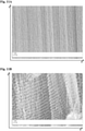
- 238000003917 TEM image Methods 0.000 description 2
- ZMZDMBWJUHKJPS-UHFFFAOYSA-M Thiocyanate anion Chemical compound [S-]C#N ZMZDMBWJUHKJPS-UHFFFAOYSA-M 0.000 description 2
- NRTOMJZYCJJWKI-UHFFFAOYSA-N Titanium nitride Chemical compound [Ti]#N NRTOMJZYCJJWKI-UHFFFAOYSA-N 0.000 description 2
- WGLPBDUCMAPZCE-UHFFFAOYSA-N Trioxochromium Chemical compound O=[Cr](=O)=O WGLPBDUCMAPZCE-UHFFFAOYSA-N 0.000 description 2
- 239000007983 Tris buffer Substances 0.000 description 2
- HCHKCACWOHOZIP-UHFFFAOYSA-N Zinc Chemical compound [Zn] HCHKCACWOHOZIP-UHFFFAOYSA-N 0.000 description 2
- 230000004913 activation Effects 0.000 description 2
- 239000003570 air Substances 0.000 description 2
- 150000001298 alcohols Chemical class 0.000 description 2
- HSFWRNGVRCDJHI-UHFFFAOYSA-N alpha-acetylene Natural products C#C HSFWRNGVRCDJHI-UHFFFAOYSA-N 0.000 description 2
- CYUOWZRAOZFACA-UHFFFAOYSA-N aluminum iron Chemical compound [Al].[Fe] CYUOWZRAOZFACA-UHFFFAOYSA-N 0.000 description 2
- 150000001408 amides Chemical class 0.000 description 2
- TZIHFWKZFHZASV-UHFFFAOYSA-N anhydrous methyl formate Natural products COC=O TZIHFWKZFHZASV-UHFFFAOYSA-N 0.000 description 2
- 150000001450 anions Chemical class 0.000 description 2
- 229910052787 antimony Inorganic materials 0.000 description 2
- WATWJIUSRGPENY-UHFFFAOYSA-N antimony atom Chemical compound [Sb] WATWJIUSRGPENY-UHFFFAOYSA-N 0.000 description 2
- 229910052785 arsenic Inorganic materials 0.000 description 2
- RQNWIZPPADIBDY-UHFFFAOYSA-N arsenic atom Chemical compound [As] RQNWIZPPADIBDY-UHFFFAOYSA-N 0.000 description 2
- 230000004888 barrier function Effects 0.000 description 2
- 229910052810 boron oxide Inorganic materials 0.000 description 2
- 239000001273 butane Substances 0.000 description 2
- 229930188620 butyrolactone Natural products 0.000 description 2
- BRPQOXSCLDDYGP-UHFFFAOYSA-N calcium oxide Chemical compound [O-2].[Ca+2] BRPQOXSCLDDYGP-UHFFFAOYSA-N 0.000 description 2
- ODINCKMPIJJUCX-UHFFFAOYSA-N calcium oxide Inorganic materials [Ca]=O ODINCKMPIJJUCX-UHFFFAOYSA-N 0.000 description 2
- 239000000292 calcium oxide Substances 0.000 description 2
- 230000003197 catalytic effect Effects 0.000 description 2
- 210000004027 cell Anatomy 0.000 description 2
- 230000008859 change Effects 0.000 description 2
- 150000001805 chlorine compounds Chemical class 0.000 description 2
- UPHIPHFJVNKLMR-UHFFFAOYSA-N chromium iron Chemical compound [Cr].[Fe] UPHIPHFJVNKLMR-UHFFFAOYSA-N 0.000 description 2
- 229910000423 chromium oxide Inorganic materials 0.000 description 2
- 238000004891 communication Methods 0.000 description 2
- 239000002131 composite material Substances 0.000 description 2
- 229920001940 conductive polymer Polymers 0.000 description 2
- PMHQVHHXPFUNSP-UHFFFAOYSA-M copper(1+);methylsulfanylmethane;bromide Chemical compound Br[Cu].CSC PMHQVHHXPFUNSP-UHFFFAOYSA-M 0.000 description 2
- 150000004292 cyclic ethers Chemical class 0.000 description 2
- 238000013500 data storage Methods 0.000 description 2
- 229910003460 diamond Inorganic materials 0.000 description 2
- 239000010432 diamond Substances 0.000 description 2
- JKWMSGQKBLHBQQ-UHFFFAOYSA-N diboron trioxide Chemical compound O=BOB=O JKWMSGQKBLHBQQ-UHFFFAOYSA-N 0.000 description 2
- QLVWOKQMDLQXNN-UHFFFAOYSA-N dibutyl carbonate Chemical compound CCCCOC(=O)OCCCC QLVWOKQMDLQXNN-UHFFFAOYSA-N 0.000 description 2
- 239000003989 dielectric material Substances 0.000 description 2
- IEJIGPNLZYLLBP-UHFFFAOYSA-N dimethyl carbonate Chemical compound COC(=O)OC IEJIGPNLZYLLBP-UHFFFAOYSA-N 0.000 description 2
- 230000005611 electricity Effects 0.000 description 2
- 239000002001 electrolyte material Substances 0.000 description 2
- 230000008030 elimination Effects 0.000 description 2
- 238000003379 elimination reaction Methods 0.000 description 2
- JBTWLSYIZRCDFO-UHFFFAOYSA-N ethyl methyl carbonate Chemical compound CCOC(=O)OC JBTWLSYIZRCDFO-UHFFFAOYSA-N 0.000 description 2
- 125000002534 ethynyl group Chemical group [H]C#C* 0.000 description 2
- 230000002349 favourable effect Effects 0.000 description 2
- 239000006260 foam Substances 0.000 description 2
- WBJINCZRORDGAQ-UHFFFAOYSA-N formic acid ethyl ester Natural products CCOC=O WBJINCZRORDGAQ-UHFFFAOYSA-N 0.000 description 2
- 229910052733 gallium Inorganic materials 0.000 description 2
- 229910052732 germanium Inorganic materials 0.000 description 2
- GNPVGFCGXDBREM-UHFFFAOYSA-N germanium atom Chemical compound [Ge] GNPVGFCGXDBREM-UHFFFAOYSA-N 0.000 description 2
- 229910002804 graphite Inorganic materials 0.000 description 2
- 239000010439 graphite Substances 0.000 description 2
- 238000009499 grossing Methods 0.000 description 2
- 229910000037 hydrogen sulfide Inorganic materials 0.000 description 2
- ZMZDMBWJUHKJPS-UHFFFAOYSA-N hydrogen thiocyanate Natural products SC#N ZMZDMBWJUHKJPS-UHFFFAOYSA-N 0.000 description 2
- 238000010348 incorporation Methods 0.000 description 2
- 229910052738 indium Inorganic materials 0.000 description 2
- APFVFJFRJDLVQX-UHFFFAOYSA-N indium atom Chemical compound [In] APFVFJFRJDLVQX-UHFFFAOYSA-N 0.000 description 2
- 238000007735 ion beam assisted deposition Methods 0.000 description 2
- KWUUWVQMAVOYKS-UHFFFAOYSA-N iron molybdenum Chemical compound [Fe].[Fe][Mo][Mo] KWUUWVQMAVOYKS-UHFFFAOYSA-N 0.000 description 2
- 150000002596 lactones Chemical class 0.000 description 2
- CPLXHLVBOLITMK-UHFFFAOYSA-N magnesium oxide Inorganic materials [Mg]=O CPLXHLVBOLITMK-UHFFFAOYSA-N 0.000 description 2
- 239000000395 magnesium oxide Substances 0.000 description 2
- AXZKOIWUVFPNLO-UHFFFAOYSA-N magnesium;oxygen(2-) Chemical compound [O-2].[Mg+2] AXZKOIWUVFPNLO-UHFFFAOYSA-N 0.000 description 2
- WPBNNNQJVZRUHP-UHFFFAOYSA-L manganese(2+);methyl n-[[2-(methoxycarbonylcarbamothioylamino)phenyl]carbamothioyl]carbamate;n-[2-(sulfidocarbothioylamino)ethyl]carbamodithioate Chemical compound [Mn+2].[S-]C(=S)NCCNC([S-])=S.COC(=O)NC(=S)NC1=CC=CC=C1NC(=S)NC(=O)OC WPBNNNQJVZRUHP-UHFFFAOYSA-L 0.000 description 2
- 238000005259 measurement Methods 0.000 description 2
- 239000002082 metal nanoparticle Substances 0.000 description 2
- 229910044991 metal oxide Inorganic materials 0.000 description 2
- 150000004706 metal oxides Chemical class 0.000 description 2
- LGRLWUINFJPLSH-UHFFFAOYSA-N methanide Chemical compound [CH3-] LGRLWUINFJPLSH-UHFFFAOYSA-N 0.000 description 2
- 229940017219 methyl propionate Drugs 0.000 description 2
- 239000010445 mica Substances 0.000 description 2
- 229910052618 mica group Inorganic materials 0.000 description 2
- IJDNQMDRQITEOD-UHFFFAOYSA-N n-butane Chemical compound CCCC IJDNQMDRQITEOD-UHFFFAOYSA-N 0.000 description 2
- 239000002105 nanoparticle Substances 0.000 description 2
- 229910052758 niobium Inorganic materials 0.000 description 2
- 239000010955 niobium Substances 0.000 description 2
- GUCVJGMIXFAOAE-UHFFFAOYSA-N niobium atom Chemical compound [Nb] GUCVJGMIXFAOAE-UHFFFAOYSA-N 0.000 description 2
- 229910052757 nitrogen Inorganic materials 0.000 description 2
- LYGJENNIWJXYER-UHFFFAOYSA-N nitromethane Chemical compound C[N+]([O-])=O LYGJENNIWJXYER-UHFFFAOYSA-N 0.000 description 2
- 230000006911 nucleation Effects 0.000 description 2
- 238000010899 nucleation Methods 0.000 description 2
- RVTZCBVAJQQJTK-UHFFFAOYSA-N oxygen(2-);zirconium(4+) Chemical compound [O-2].[O-2].[Zr+4] RVTZCBVAJQQJTK-UHFFFAOYSA-N 0.000 description 2
- 230000035515 penetration Effects 0.000 description 2
- 230000000737 periodic effect Effects 0.000 description 2
- 230000000704 physical effect Effects 0.000 description 2
- 229920001223 polyethylene glycol Polymers 0.000 description 2
- 238000003825 pressing Methods 0.000 description 2
- 239000001294 propane Substances 0.000 description 2
- RUOJZAUFBMNUDX-UHFFFAOYSA-N propylene carbonate Chemical compound CC1COC(=O)O1 RUOJZAUFBMNUDX-UHFFFAOYSA-N 0.000 description 2
- 238000003908 quality control method Methods 0.000 description 2
- 238000011084 recovery Methods 0.000 description 2
- 150000003839 salts Chemical class 0.000 description 2
- 239000000377 silicon dioxide Substances 0.000 description 2
- HQVNEWCFYHHQES-UHFFFAOYSA-N silicon nitride Chemical compound N12[Si]34N5[Si]62N3[Si]51N64 HQVNEWCFYHHQES-UHFFFAOYSA-N 0.000 description 2
- 239000002356 single layer Substances 0.000 description 2
- 239000002109 single walled nanotube Substances 0.000 description 2
- 239000007921 spray Substances 0.000 description 2
- 238000005507 spraying Methods 0.000 description 2
- HXJUTPCZVOIRIF-UHFFFAOYSA-N sulfolane Chemical compound O=S1(=O)CCCC1 HXJUTPCZVOIRIF-UHFFFAOYSA-N 0.000 description 2
- 229930192474 thiophene Natural products 0.000 description 2
- OGIDPMRJRNCKJF-UHFFFAOYSA-N titanium oxide Inorganic materials [Ti]=O OGIDPMRJRNCKJF-UHFFFAOYSA-N 0.000 description 2
- MAKDTFFYCIMFQP-UHFFFAOYSA-N titanium tungsten Chemical compound [Ti].[W] MAKDTFFYCIMFQP-UHFFFAOYSA-N 0.000 description 2
- ZIBGPFATKBEMQZ-UHFFFAOYSA-N triethylene glycol Chemical compound OCCOCCOCCO ZIBGPFATKBEMQZ-UHFFFAOYSA-N 0.000 description 2
- 230000008016 vaporization Effects 0.000 description 2
- 239000011800 void material Substances 0.000 description 2
- 229910052725 zinc Inorganic materials 0.000 description 2
- 239000011701 zinc Substances 0.000 description 2
- 239000011787 zinc oxide Substances 0.000 description 2
- 229910001928 zirconium oxide Inorganic materials 0.000 description 2
- VSTNJXMWIRGZOX-UHFFFAOYSA-N 1,3-diethoxyimidazol-1-ium Chemical compound CCON1C=C[N+](OCC)=C1 VSTNJXMWIRGZOX-UHFFFAOYSA-N 0.000 description 1
- QTBSBXVTEAMEQO-UHFFFAOYSA-M Acetate Chemical compound CC([O-])=O QTBSBXVTEAMEQO-UHFFFAOYSA-M 0.000 description 1
- 229910018072 Al 2 O 3 Inorganic materials 0.000 description 1
- QGZKDVFQNNGYKY-UHFFFAOYSA-O Ammonium Chemical compound [NH4+] QGZKDVFQNNGYKY-UHFFFAOYSA-O 0.000 description 1
- BVKZGUZCCUSVTD-UHFFFAOYSA-L Carbonate Chemical compound [O-]C([O-])=O BVKZGUZCCUSVTD-UHFFFAOYSA-L 0.000 description 1
- ZAMOUSCENKQFHK-UHFFFAOYSA-N Chlorine atom Chemical compound [Cl] ZAMOUSCENKQFHK-UHFFFAOYSA-N 0.000 description 1
- 229910017060 Fe Cr Inorganic materials 0.000 description 1
- 229910002544 Fe-Cr Inorganic materials 0.000 description 1
- 206010021143 Hypoxia Diseases 0.000 description 1
- 229910001030 Iron–nickel alloy Inorganic materials 0.000 description 1
- 241000549556 Nanos Species 0.000 description 1
- GRYLNZFGIOXLOG-UHFFFAOYSA-N Nitric acid Chemical compound O[N+]([O-])=O GRYLNZFGIOXLOG-UHFFFAOYSA-N 0.000 description 1
- CBENFWSGALASAD-UHFFFAOYSA-N Ozone Chemical compound [O-][O+]=O CBENFWSGALASAD-UHFFFAOYSA-N 0.000 description 1
- OAICVXFJPJFONN-UHFFFAOYSA-N Phosphorus Chemical compound [P] OAICVXFJPJFONN-UHFFFAOYSA-N 0.000 description 1
- NQRYJNQNLNOLGT-UHFFFAOYSA-O Piperidinium(1+) Chemical compound C1CC[NH2+]CC1 NQRYJNQNLNOLGT-UHFFFAOYSA-O 0.000 description 1
- RWRDLPDLKQPQOW-UHFFFAOYSA-O Pyrrolidinium ion Chemical compound C1CC[NH2+]C1 RWRDLPDLKQPQOW-UHFFFAOYSA-O 0.000 description 1
- 229920006362 Teflon® Polymers 0.000 description 1
- 238000005411 Van der Waals force Methods 0.000 description 1
- 239000006096 absorbing agent Substances 0.000 description 1
- 239000002253 acid Substances 0.000 description 1
- 239000011149 active material Substances 0.000 description 1
- 239000000853 adhesive Substances 0.000 description 1
- 230000001070 adhesive effect Effects 0.000 description 1
- 239000002390 adhesive tape Substances 0.000 description 1
- 238000005054 agglomeration Methods 0.000 description 1
- 230000002776 aggregation Effects 0.000 description 1
- 150000001299 aldehydes Chemical class 0.000 description 1
- 239000012080 ambient air Substances 0.000 description 1
- 239000003963 antioxidant agent Substances 0.000 description 1
- 230000003078 antioxidant effect Effects 0.000 description 1
- 229910052786 argon Inorganic materials 0.000 description 1
- 238000013475 authorization Methods 0.000 description 1
- 238000003287 bathing Methods 0.000 description 1
- 230000009286 beneficial effect Effects 0.000 description 1
- 239000006227 byproduct Substances 0.000 description 1
- 150000001722 carbon compounds Chemical class 0.000 description 1
- 239000011203 carbon fibre reinforced carbon Substances 0.000 description 1
- 229910021386 carbon form Inorganic materials 0.000 description 1
- 238000003763 carbonization Methods 0.000 description 1
- 238000010000 carbonizing Methods 0.000 description 1
- 230000015556 catabolic process Effects 0.000 description 1
- 239000000460 chlorine Substances 0.000 description 1
- 229910052801 chlorine Inorganic materials 0.000 description 1
- BIJOYKCOMBZXAE-UHFFFAOYSA-N chromium iron nickel Chemical compound [Cr].[Fe].[Ni] BIJOYKCOMBZXAE-UHFFFAOYSA-N 0.000 description 1
- 238000004140 cleaning Methods 0.000 description 1
- 238000010835 comparative analysis Methods 0.000 description 1
- 239000000470 constituent Substances 0.000 description 1
- 239000002826 coolant Substances 0.000 description 1
- 238000002788 crimping Methods 0.000 description 1
- 230000009849 deactivation Effects 0.000 description 1
- 230000002950 deficient Effects 0.000 description 1
- 238000006731 degradation reaction Methods 0.000 description 1
- 230000032798 delamination Effects 0.000 description 1
- 238000000280 densification Methods 0.000 description 1
- 230000001419 dependent effect Effects 0.000 description 1
- 230000001066 destructive effect Effects 0.000 description 1
- 230000006866 deterioration Effects 0.000 description 1
- 238000009826 distribution Methods 0.000 description 1
- 230000005674 electromagnetic induction Effects 0.000 description 1
- 238000010894 electron beam technology Methods 0.000 description 1
- 150000002148 esters Chemical class 0.000 description 1
- 150000002170 ethers Chemical class 0.000 description 1
- 238000011156 evaluation Methods 0.000 description 1
- 239000010419 fine particle Substances 0.000 description 1
- 238000007730 finishing process Methods 0.000 description 1
- HWKLQEMZQGCUKW-UHFFFAOYSA-N fluorooxy(trifluoromethoxy)borinic acid Chemical compound FOB(O)OC(F)(F)F HWKLQEMZQGCUKW-UHFFFAOYSA-N 0.000 description 1
- 229920002313 fluoropolymer Polymers 0.000 description 1
- 239000004811 fluoropolymer Substances 0.000 description 1
- 238000009472 formulation Methods 0.000 description 1
- 239000003365 glass fiber Substances 0.000 description 1
- 230000009477 glass transition Effects 0.000 description 1
- 239000002241 glass-ceramic Substances 0.000 description 1
- 230000005484 gravity Effects 0.000 description 1
- 239000001307 helium Substances 0.000 description 1
- 229910052734 helium Inorganic materials 0.000 description 1
- SWQJXJOGLNCZEY-UHFFFAOYSA-N helium atom Chemical compound [He] SWQJXJOGLNCZEY-UHFFFAOYSA-N 0.000 description 1
- 229930195733 hydrocarbon Natural products 0.000 description 1
- 150000002430 hydrocarbons Chemical class 0.000 description 1
- 150000002431 hydrogen Chemical class 0.000 description 1
- 230000001146 hypoxic effect Effects 0.000 description 1
- 230000006872 improvement Effects 0.000 description 1
- 210000003000 inclusion body Anatomy 0.000 description 1
- AMGQUBHHOARCQH-UHFFFAOYSA-N indium;oxotin Chemical compound [In].[Sn]=O AMGQUBHHOARCQH-UHFFFAOYSA-N 0.000 description 1
- 239000004615 ingredient Substances 0.000 description 1
- 238000002347 injection Methods 0.000 description 1
- 239000007924 injection Substances 0.000 description 1
- 230000003993 interaction Effects 0.000 description 1
- 238000001888 ion beam-induced deposition Methods 0.000 description 1
- 239000002608 ionic liquid Substances 0.000 description 1
- UGKDIUIOSMUOAW-UHFFFAOYSA-N iron nickel Chemical compound [Fe].[Ni] UGKDIUIOSMUOAW-UHFFFAOYSA-N 0.000 description 1
- 230000001788 irregular Effects 0.000 description 1
- 230000002427 irreversible effect Effects 0.000 description 1
- 235000015110 jellies Nutrition 0.000 description 1
- 239000008274 jelly Substances 0.000 description 1
- 150000002576 ketones Chemical class 0.000 description 1
- 229910052743 krypton Inorganic materials 0.000 description 1
- DNNSSWSSYDEUBZ-UHFFFAOYSA-N krypton atom Chemical compound [Kr] DNNSSWSSYDEUBZ-UHFFFAOYSA-N 0.000 description 1
- 238000003475 lamination Methods 0.000 description 1
- 239000007788 liquid Substances 0.000 description 1
- 238000012423 maintenance Methods 0.000 description 1
- 230000007246 mechanism Effects 0.000 description 1
- 229910052987 metal hydride Inorganic materials 0.000 description 1
- 150000004681 metal hydrides Chemical class 0.000 description 1
- 239000007769 metal material Substances 0.000 description 1
- 238000000465 moulding Methods 0.000 description 1
- 239000002086 nanomaterial Substances 0.000 description 1
- 229910052754 neon Inorganic materials 0.000 description 1
- GKAOGPIIYCISHV-UHFFFAOYSA-N neon atom Chemical compound [Ne] GKAOGPIIYCISHV-UHFFFAOYSA-N 0.000 description 1
- 229910017604 nitric acid Inorganic materials 0.000 description 1
- 150000004767 nitrides Chemical class 0.000 description 1
- 229910052756 noble gas Inorganic materials 0.000 description 1
- 150000002843 nonmetals Chemical class 0.000 description 1
- 125000001741 organic sulfur group Chemical group 0.000 description 1
- 230000036961 partial effect Effects 0.000 description 1
- 239000012071 phase Substances 0.000 description 1
- 238000000206 photolithography Methods 0.000 description 1
- 238000004375 physisorption Methods 0.000 description 1
- 229920001296 polysiloxane Polymers 0.000 description 1
- 239000011148 porous material Substances 0.000 description 1
- 239000000843 powder Substances 0.000 description 1
- 238000004886 process control Methods 0.000 description 1
- 238000004540 process dynamic Methods 0.000 description 1
- 238000011112 process operation Methods 0.000 description 1
- 238000003672 processing method Methods 0.000 description 1
- 230000001681 protective effect Effects 0.000 description 1
- 239000011241 protective layer Substances 0.000 description 1
- 239000003507 refrigerant Substances 0.000 description 1
- 230000002787 reinforcement Effects 0.000 description 1
- 230000003252 repetitive effect Effects 0.000 description 1
- 238000011160 research Methods 0.000 description 1
- 230000002441 reversible effect Effects 0.000 description 1
- 238000007789 sealing Methods 0.000 description 1
- 239000004065 semiconductor Substances 0.000 description 1
- 230000035939 shock Effects 0.000 description 1
- 239000007787 solid Substances 0.000 description 1
- 239000011949 solid catalyst Substances 0.000 description 1
- 241000894007 species Species 0.000 description 1
- 210000000352 storage cell Anatomy 0.000 description 1
- 230000002459 sustained effect Effects 0.000 description 1
- 238000009210 therapy by ultrasound Methods 0.000 description 1
- CCZXMDQFIVMWMF-UHFFFAOYSA-N trifluoromethoxyboronic acid Chemical compound OB(O)OC(F)(F)F CCZXMDQFIVMWMF-UHFFFAOYSA-N 0.000 description 1
- 239000012808 vapor phase Substances 0.000 description 1
- 238000009834 vaporization Methods 0.000 description 1
- 239000006200 vaporizer Substances 0.000 description 1
Images


Classifications
-
- H—ELECTRICITY
- H01—ELECTRIC ELEMENTS
- H01G—CAPACITORS; CAPACITORS, RECTIFIERS, DETECTORS, SWITCHING DEVICES, LIGHT-SENSITIVE OR TEMPERATURE-SENSITIVE DEVICES OF THE ELECTROLYTIC TYPE
- H01G11/00—Hybrid capacitors, i.e. capacitors having different positive and negative electrodes; Electric double-layer [EDL] capacitors; Processes for the manufacture thereof or of parts thereof
- H01G11/22—Electrodes
- H01G11/26—Electrodes characterised by their structure, e.g. multi-layered, porosity or surface features
- H01G11/28—Electrodes characterised by their structure, e.g. multi-layered, porosity or surface features arranged or disposed on a current collector; Layers or phases between electrodes and current collectors, e.g. adhesives
-
- B—PERFORMING OPERATIONS; TRANSPORTING
- B82—NANOTECHNOLOGY
- B82Y—SPECIFIC USES OR APPLICATIONS OF NANOSTRUCTURES; MEASUREMENT OR ANALYSIS OF NANOSTRUCTURES; MANUFACTURE OR TREATMENT OF NANOSTRUCTURES
- B82Y30/00—Nanotechnology for materials or surface science, e.g. nanocomposites
-
- B—PERFORMING OPERATIONS; TRANSPORTING
- B82—NANOTECHNOLOGY
- B82Y—SPECIFIC USES OR APPLICATIONS OF NANOSTRUCTURES; MEASUREMENT OR ANALYSIS OF NANOSTRUCTURES; MANUFACTURE OR TREATMENT OF NANOSTRUCTURES
- B82Y40/00—Manufacture or treatment of nanostructures
-
- C—CHEMISTRY; METALLURGY
- C01—INORGANIC CHEMISTRY
- C01B—NON-METALLIC ELEMENTS; COMPOUNDS THEREOF; METALLOIDS OR COMPOUNDS THEREOF NOT COVERED BY SUBCLASS C01C
- C01B32/00—Carbon; Compounds thereof
- C01B32/15—Nano-sized carbon materials
- C01B32/158—Carbon nanotubes
- C01B32/16—Preparation
- C01B32/162—Preparation characterised by catalysts
-
- H—ELECTRICITY
- H01—ELECTRIC ELEMENTS
- H01G—CAPACITORS; CAPACITORS, RECTIFIERS, DETECTORS, SWITCHING DEVICES, LIGHT-SENSITIVE OR TEMPERATURE-SENSITIVE DEVICES OF THE ELECTROLYTIC TYPE
- H01G11/00—Hybrid capacitors, i.e. capacitors having different positive and negative electrodes; Electric double-layer [EDL] capacitors; Processes for the manufacture thereof or of parts thereof
- H01G11/22—Electrodes
- H01G11/30—Electrodes characterised by their material
- H01G11/32—Carbon-based
- H01G11/36—Nanostructures, e.g. nanofibres, nanotubes or fullerenes
-
- H—ELECTRICITY
- H01—ELECTRIC ELEMENTS
- H01G—CAPACITORS; CAPACITORS, RECTIFIERS, DETECTORS, SWITCHING DEVICES, LIGHT-SENSITIVE OR TEMPERATURE-SENSITIVE DEVICES OF THE ELECTROLYTIC TYPE
- H01G11/00—Hybrid capacitors, i.e. capacitors having different positive and negative electrodes; Electric double-layer [EDL] capacitors; Processes for the manufacture thereof or of parts thereof
- H01G11/66—Current collectors
- H01G11/68—Current collectors characterised by their material
-
- H—ELECTRICITY
- H01—ELECTRIC ELEMENTS
- H01G—CAPACITORS; CAPACITORS, RECTIFIERS, DETECTORS, SWITCHING DEVICES, LIGHT-SENSITIVE OR TEMPERATURE-SENSITIVE DEVICES OF THE ELECTROLYTIC TYPE
- H01G9/00—Electrolytic capacitors, rectifiers, detectors, switching devices, light-sensitive or temperature-sensitive devices; Processes of their manufacture
- H01G9/20—Light-sensitive devices
- H01G9/2004—Light-sensitive devices characterised by the electrolyte, e.g. comprising an organic electrolyte
-
- C—CHEMISTRY; METALLURGY
- C01—INORGANIC CHEMISTRY
- C01B—NON-METALLIC ELEMENTS; COMPOUNDS THEREOF; METALLOIDS OR COMPOUNDS THEREOF NOT COVERED BY SUBCLASS C01C
- C01B2202/00—Structure or properties of carbon nanotubes
- C01B2202/04—Nanotubes with a specific amount of walls
-
- C—CHEMISTRY; METALLURGY
- C01—INORGANIC CHEMISTRY
- C01B—NON-METALLIC ELEMENTS; COMPOUNDS THEREOF; METALLOIDS OR COMPOUNDS THEREOF NOT COVERED BY SUBCLASS C01C
- C01B2202/00—Structure or properties of carbon nanotubes
- C01B2202/20—Nanotubes characterized by their properties
- C01B2202/32—Specific surface area
-
- C—CHEMISTRY; METALLURGY
- C01—INORGANIC CHEMISTRY
- C01B—NON-METALLIC ELEMENTS; COMPOUNDS THEREOF; METALLOIDS OR COMPOUNDS THEREOF NOT COVERED BY SUBCLASS C01C
- C01B2202/00—Structure or properties of carbon nanotubes
- C01B2202/20—Nanotubes characterized by their properties
- C01B2202/34—Length
-
- C—CHEMISTRY; METALLURGY
- C01—INORGANIC CHEMISTRY
- C01B—NON-METALLIC ELEMENTS; COMPOUNDS THEREOF; METALLOIDS OR COMPOUNDS THEREOF NOT COVERED BY SUBCLASS C01C
- C01B2202/00—Structure or properties of carbon nanotubes
- C01B2202/20—Nanotubes characterized by their properties
- C01B2202/36—Diameter
-
- H—ELECTRICITY
- H01—ELECTRIC ELEMENTS
- H01G—CAPACITORS; CAPACITORS, RECTIFIERS, DETECTORS, SWITCHING DEVICES, LIGHT-SENSITIVE OR TEMPERATURE-SENSITIVE DEVICES OF THE ELECTROLYTIC TYPE
- H01G11/00—Hybrid capacitors, i.e. capacitors having different positive and negative electrodes; Electric double-layer [EDL] capacitors; Processes for the manufacture thereof or of parts thereof
- H01G11/84—Processes for the manufacture of hybrid or EDL capacitors, or components thereof
-
- H—ELECTRICITY
- H01—ELECTRIC ELEMENTS
- H01G—CAPACITORS; CAPACITORS, RECTIFIERS, DETECTORS, SWITCHING DEVICES, LIGHT-SENSITIVE OR TEMPERATURE-SENSITIVE DEVICES OF THE ELECTROLYTIC TYPE
- H01G9/00—Electrolytic capacitors, rectifiers, detectors, switching devices, light-sensitive or temperature-sensitive devices; Processes of their manufacture
- H01G9/20—Light-sensitive devices
- H01G9/2004—Light-sensitive devices characterised by the electrolyte, e.g. comprising an organic electrolyte
- H01G9/2009—Solid electrolytes
-
- H—ELECTRICITY
- H01—ELECTRIC ELEMENTS
- H01G—CAPACITORS; CAPACITORS, RECTIFIERS, DETECTORS, SWITCHING DEVICES, LIGHT-SENSITIVE OR TEMPERATURE-SENSITIVE DEVICES OF THE ELECTROLYTIC TYPE
- H01G9/00—Electrolytic capacitors, rectifiers, detectors, switching devices, light-sensitive or temperature-sensitive devices; Processes of their manufacture
- H01G9/20—Light-sensitive devices
- H01G9/2004—Light-sensitive devices characterised by the electrolyte, e.g. comprising an organic electrolyte
- H01G9/2013—Light-sensitive devices characterised by the electrolyte, e.g. comprising an organic electrolyte the electrolyte comprising ionic liquids, e.g. alkyl imidazolium iodide
-
- H—ELECTRICITY
- H01—ELECTRIC ELEMENTS
- H01G—CAPACITORS; CAPACITORS, RECTIFIERS, DETECTORS, SWITCHING DEVICES, LIGHT-SENSITIVE OR TEMPERATURE-SENSITIVE DEVICES OF THE ELECTROLYTIC TYPE
- H01G9/00—Electrolytic capacitors, rectifiers, detectors, switching devices, light-sensitive or temperature-sensitive devices; Processes of their manufacture
- H01G9/20—Light-sensitive devices
- H01G9/2004—Light-sensitive devices characterised by the electrolyte, e.g. comprising an organic electrolyte
- H01G9/2018—Light-sensitive devices characterised by the electrolyte, e.g. comprising an organic electrolyte characterised by the ionic charge transport species, e.g. redox shuttles
-
- H—ELECTRICITY
- H02—GENERATION; CONVERSION OR DISTRIBUTION OF ELECTRIC POWER
- H02J—CIRCUIT ARRANGEMENTS OR SYSTEMS FOR SUPPLYING OR DISTRIBUTING ELECTRIC POWER; SYSTEMS FOR STORING ELECTRIC ENERGY
- H02J7/00—Circuit arrangements for charging or depolarising batteries or for supplying loads from batteries
- H02J7/34—Parallel operation in networks using both storage and other DC sources, e.g. providing buffering
- H02J7/345—Parallel operation in networks using both storage and other DC sources, e.g. providing buffering using capacitors as storage or buffering devices
-
- Y—GENERAL TAGGING OF NEW TECHNOLOGICAL DEVELOPMENTS; GENERAL TAGGING OF CROSS-SECTIONAL TECHNOLOGIES SPANNING OVER SEVERAL SECTIONS OF THE IPC; TECHNICAL SUBJECTS COVERED BY FORMER USPC CROSS-REFERENCE ART COLLECTIONS [XRACs] AND DIGESTS
- Y02—TECHNOLOGIES OR APPLICATIONS FOR MITIGATION OR ADAPTATION AGAINST CLIMATE CHANGE
- Y02E—REDUCTION OF GREENHOUSE GAS [GHG] EMISSIONS, RELATED TO ENERGY GENERATION, TRANSMISSION OR DISTRIBUTION
- Y02E10/00—Energy generation through renewable energy sources
- Y02E10/50—Photovoltaic [PV] energy
- Y02E10/542—Dye sensitized solar cells
-
- Y—GENERAL TAGGING OF NEW TECHNOLOGICAL DEVELOPMENTS; GENERAL TAGGING OF CROSS-SECTIONAL TECHNOLOGIES SPANNING OVER SEVERAL SECTIONS OF THE IPC; TECHNICAL SUBJECTS COVERED BY FORMER USPC CROSS-REFERENCE ART COLLECTIONS [XRACs] AND DIGESTS
- Y02—TECHNOLOGIES OR APPLICATIONS FOR MITIGATION OR ADAPTATION AGAINST CLIMATE CHANGE
- Y02E—REDUCTION OF GREENHOUSE GAS [GHG] EMISSIONS, RELATED TO ENERGY GENERATION, TRANSMISSION OR DISTRIBUTION
- Y02E60/00—Enabling technologies; Technologies with a potential or indirect contribution to GHG emissions mitigation
- Y02E60/13—Energy storage using capacitors
-
- Y—GENERAL TAGGING OF NEW TECHNOLOGICAL DEVELOPMENTS; GENERAL TAGGING OF CROSS-SECTIONAL TECHNOLOGIES SPANNING OVER SEVERAL SECTIONS OF THE IPC; TECHNICAL SUBJECTS COVERED BY FORMER USPC CROSS-REFERENCE ART COLLECTIONS [XRACs] AND DIGESTS
- Y02—TECHNOLOGIES OR APPLICATIONS FOR MITIGATION OR ADAPTATION AGAINST CLIMATE CHANGE
- Y02P—CLIMATE CHANGE MITIGATION TECHNOLOGIES IN THE PRODUCTION OR PROCESSING OF GOODS
- Y02P70/00—Climate change mitigation technologies in the production process for final industrial or consumer products
- Y02P70/50—Manufacturing or production processes characterised by the final manufactured product
-
- Y—GENERAL TAGGING OF NEW TECHNOLOGICAL DEVELOPMENTS; GENERAL TAGGING OF CROSS-SECTIONAL TECHNOLOGIES SPANNING OVER SEVERAL SECTIONS OF THE IPC; TECHNICAL SUBJECTS COVERED BY FORMER USPC CROSS-REFERENCE ART COLLECTIONS [XRACs] AND DIGESTS
- Y10—TECHNICAL SUBJECTS COVERED BY FORMER USPC
- Y10T—TECHNICAL SUBJECTS COVERED BY FORMER US CLASSIFICATION
- Y10T156/00—Adhesive bonding and miscellaneous chemical manufacture
- Y10T156/10—Methods of surface bonding and/or assembly therefor
Landscapes
- Engineering & Computer Science (AREA)
- Chemical & Material Sciences (AREA)
- Power Engineering (AREA)
- Nanotechnology (AREA)
- Materials Engineering (AREA)
- Microelectronics & Electronic Packaging (AREA)
- Crystallography & Structural Chemistry (AREA)
- Chemical Kinetics & Catalysis (AREA)
- General Physics & Mathematics (AREA)
- Condensed Matter Physics & Semiconductors (AREA)
- Physics & Mathematics (AREA)
- Organic Chemistry (AREA)
- Electrochemistry (AREA)
- Manufacturing & Machinery (AREA)
- Composite Materials (AREA)
- Inorganic Chemistry (AREA)
- Electric Double-Layer Capacitors Or The Like (AREA)
- Carbon And Carbon Compounds (AREA)
- Manufacturing Of Micro-Capsules (AREA)
Description
[連邦政府支援による研究の申告]
本発明は、米国エネルギー省によって授与された認可DE-AR0000035/0001の下で政府の援助によってなされた(ARPA-E)。米国政府は本発明に一定の権利を有する。
[Federal-supported research declaration]
The present invention has been made with government assistance under the authorization DE-AR00000035 / 0001 awarded by the US Department of Energy (ARPA-E). The US Government has certain rights to the invention.
本発明は概括的にはキャパシタに関し、より具体的にはキャパシタに用いられるカーボンナノチューブに関する。 The present invention relates generally to capacitors, and more specifically to carbon nanotubes used in capacitors.
カーボンナノチューブ(以下、「CNT」ともよぶ)は、種々の特性を示す炭素構造体である。多数の特性が種々の科学技術における改良の機会を示唆している。例えば、強度、伝導度または静電容量(キャパシタンス)の増大から利益を得る技術は、CNTの使用から利益を得るだろう。従って、CNT技術における進歩は、キャパシタを扱う仕事に従事している人々にとって非常に興味深い。 Carbon nanotubes (hereinafter, also referred to as “CNT”) are carbon structures exhibiting various properties. Numerous properties suggest opportunities for improvement in various science and technology. For example, techniques that benefit from increased strength, conductivity or capacitance will benefit from the use of CNTs. Therefore, advances in CNT technology are of great interest to those engaged in the work of working with capacitors.
キャパシタは、種々の電気システムにおいて重要な構成要素の1つである。機能としては、電力の緩衝(またはバッファリング)、エネルギーの貯蔵および電圧の平滑化(またはスムージング)が挙げられる。種々の産業がキャパシタに対して厳しい要求を示している。 Capacitors are one of the important components in various electrical systems. Functions include power buffering (or buffering), energy storage and voltage smoothing (or smoothing). Various industries are showing strict demands on capacitors.
例えば、自動車、製造業、航空宇宙産業、航空機産業、医療および軍事等の産業は、電気駆動、パルス電力またはプロセス作動にエネルギーまたは電力支援を提供するためにキャパシタを必要とするいくつかの用途を有することを考える。エネルギー容量および電力の能力は、それらの産業における代表的な用途において重要な要件である。電気駆動系(またはドライブトレイン)におけるトルクアシスト(またはトルク補助)、製造プラントにおけるモーター駆動のためのパワーアシスト(または動力補助)または高出力負荷需要の間の電圧サポート(または電圧補助)の提供等の用途は、かなりのエネルギーおよび電力を必要とする。いくつかの用途は制限された物理的スペースまたは重量の上限を示す。いくつかの用途は長いサイクル寿命を必要とする。 For example, industries such as automotive, manufacturing, aerospace, aviation, medical and military have several applications that require capacitors to provide energy or power support for electrical drive, pulse power or process operation. Think about having. Energy capacity and power capacity are important requirements for typical applications in those industries. Providing torque assist (or torque assist) in an electric drive system (or drive train), power assist (or power assist) for motor drive in a manufacturing plant, or voltage support (or voltage assist) during high output load demands, etc. Applications require considerable energy and power. Some uses indicate a limited physical space or weight limit. Some applications require a long cycle life.
従って、産業環境において用いられるキャパシタは、物理的制約を満たしつつ性能に関する要件を満たさなければならない。ウルトラキャパシタの設計者および製造者にとって、付随する課題の1つは所望の出力で機能する電極を得ることである。 Therefore, capacitors used in an industrial environment must meet performance requirements while meeting physical constraints. One of the accompanying challenges for ultracapacitor designers and manufacturers is to obtain electrodes that function at the desired output.
従って、カーボンナノチューブをベースとする高出力の電極を製造するための方法および装置が必要とされる。好ましくは、方法および装置は実行が簡単であり、従って製造コストの低減および生産率(または工率)の向上を提供する。好ましくは、方法および装置は、要求が多い状況において十分に機能するウルトラキャパシタのための電極を提供する。好ましくは、電極は、広い温度範囲にわたって安定な伝導度および低い内部抵抗をもたらす。 Therefore, there is a need for methods and equipment for producing high power electrodes based on carbon nanotubes. Preferably, the methods and appliances are easy to implement and thus provide a reduction in manufacturing costs and an increase in power (or power). Preferably, the methods and devices provide electrodes for ultracapacitors that work well in demanding situations. Preferably, the electrode provides stable conductivity and low internal resistance over a wide temperature range.
カーボンナノチューブを製造するための方法および装置が提供される。方法および装置は、優れた特性、従って種々の用途において用いる際の優れた性能を示すカーボンナノチューブを提供する。電極およびウルトラキャパシタの種々の形態が結果として理解され得る。 Methods and devices for producing carbon nanotubes are provided. Methods and devices provide carbon nanotubes that exhibit excellent properties and thus excellent performance when used in a variety of applications. Various forms of electrodes and ultracapacitors can be understood as a result.
一の実施形態において、垂直に配列されたカーボンナノチューブの集合体の製造方法が提供される。方法は、実質的に酸素のない環境中に基材を装着すること;基材上に触媒を配置して基体を提供すること;基体を原材料ガスに付し、基体上に集合体を成長させるために原材料ガスおよび基体の少なくとも一方を加熱すること;ならびに実質的に酸素のない環境において集合体を冷却することを含む。 In one embodiment, a method for producing an aggregate of vertically arranged carbon nanotubes is provided. The method is to mount the substrate in a substantially oxygen-free environment; place a catalyst on the substrate to provide the substrate; attach the substrate to the raw material gas and grow the aggregate on the substrate. To heat at least one of the raw material gas and the substrate; and include cooling the aggregate in a virtually oxygen-free environment.
もう1つの実施形態において、垂直に配列されたカーボンナノチューブの集合体を製造する装置が提供される。この装置は、実質的に酸素のない環境中に基材を装着するためのローダー部:基材上に触媒を配置して基体を提供するためのスパッタリング部;基体を原材料ガスに付し、基体上に集合体を成長させるために原材料ガスおよび基体の少なくとも一方を加熱するための炭素沈積部;ならびに実質的に酸素のない環境において集合体を冷却するための冷却部を含む。 In another embodiment, an apparatus is provided for producing an aggregate of vertically arranged carbon nanotubes. This device is a loader unit for mounting a substrate in a substantially oxygen-free environment: a sputtering unit for arranging a catalyst on the substrate to provide the substrate; the substrate is attached to a raw material gas and the substrate is attached. Includes a carbon deposit for heating at least one of the raw material gas and the substrate to grow the aggregate on top; and a cooling unit for cooling the aggregate in a virtually oxygen-free environment.
もう1つの実施形態において、ウルトラキャパシタの電極の製造方法であって、電極が垂直に配列されたカーボンナノチューブの集合体を含む、方法が提供される。方法は、実質的に酸素のない環境中に基材を装着すること;基材上に触媒を配置して基体を提供すること;基体を原材料ガスに付し、原材料ガスおよび基体の少なくとも一方を加熱して基体上に集合体を成長させること;ならびに実質的に酸素のない環境において集合体を冷却することによって製造された集合体を選択することと、集合体を集電体と接合すること、集合体を基体から取り外して集電体を集合体上に配置すること、および集合体を他の炭素質材料と組み合わせてその組み合わせを集電体と接合することの1つとを含む。 In another embodiment, there is provided a method of making an electrode of an ultracapacitor, which comprises an aggregate of carbon nanotubes in which the electrodes are vertically arranged. The method is to mount the substrate in a substantially oxygen-free environment; place a catalyst on the substrate to provide the substrate; attach the substrate to the raw material gas and attach at least one of the raw material gas and the substrate. To grow an aggregate on a substrate by heating; as well as to select an aggregate produced by cooling the aggregate in a virtually oxygen-free environment, and to join the aggregate to a current collector. It includes removing the aggregate from the substrate and placing the collector on the aggregate, and combining the aggregate with other carbonaceous materials and joining the combination to the collector.
もう1つの実施形態において、エネルギー貯蔵システムのための電極の製造方法が提供される。方法は、上に配置された一の厚さの垂直に配列されたカーボンナノチューブ(CNT)を含む基体を選択すること;前記厚さのCNT上に結合層を配置すること;結合層を集電体と結合させること;およびCNTから基体を除去して電極を提供することを含む。 In another embodiment, a method of manufacturing electrodes for an energy storage system is provided. The method is to select a substrate containing one thickness of vertically arranged carbon nanotubes (CNTs) placed on top; to place a bond layer on the CNTs of said thickness; to collect the bond layer. Includes binding to the body; and removing the substrate from the CNTs to provide the electrodes.
もう1つの実施形態において、ウルトラキャパシタの製造方法であって、ウルトラキャパシタは、垂直に配列されたカーボンナノチューブの集合体を含む少なくとも1つの電極を含む、方法が提供される。方法は、実質的に酸素のない環境中に基材を装着すること;基材上に触媒を配置して基体を提供すること;基体を原材料ガスに付し、原材料ガスおよび基体の少なくとも一方を加熱して基体上に集合体を成長させること;ならびに実質的に酸素のない環境において集合体を冷却することによって製造された集合体を選択することと、集合体を集電体上に移動させること、基体から集合体を取り外して集合体上に集電体を配置すること、および集合体を集電体上で他の炭素質材料と組み合わせて電極を提供することの1つとによって製造された電極を選択すること;ならびに電極をウルトラキャパシタに組み込むことを含む。 In another embodiment, there is provided a method of making an ultracapacitor, wherein the ultracapacitor comprises at least one electrode comprising an aggregate of vertically arranged carbon nanotubes. The method is to mount the substrate in a substantially oxygen-free environment; place a catalyst on the substrate to provide the substrate; attach the substrate to the raw material gas and attach at least one of the raw material gas and the substrate. To grow the aggregate on the substrate by heating; as well as to select the aggregate produced by cooling the aggregate in a virtually oxygen-free environment and to move the aggregate onto the current collector. Manufactured by removing the aggregate from the substrate and placing the aggregate on the aggregate, and combining the aggregate on the collector with other carbonaceous materials to provide electrodes. Selecting electrodes; as well as incorporating the electrodes into an ultracapsule.
もう1つの実施形態において、エネルギー貯蔵システムのための電極の製造方法が提供される。方法は、集電体と、集電体の表面に配置された第1の接合層とを含む基部を選択すること;および第2の接合層を第1の接合層と接合することであって、第2の接合層はその上に配置された炭素質層を含み、炭素質層は電荷を貯蔵するための材料を含む、ことを含む。 In another embodiment, a method of manufacturing electrodes for an energy storage system is provided. The method is to select a base containing a current collector and a first bonding layer located on the surface of the current collector; and joining the second bonding layer to the first bonding layer. , The second junction layer comprises a carbonaceous layer disposed on it, the carbonaceous layer comprising a material for storing charges.
もう1つの実施形態において、電極が提供される。電極は、集電体と、集電体の表面に配置された第1の接合層とを含む基部;および第1の接合層と接合された第2の接合層であって、第2の接合層は、その上に配置された炭素質層を含み、炭素質層は電荷を貯蔵するための材料を含む、第2の接合層を含む。 In another embodiment, electrodes are provided. The electrode is a base including a current collector and a first bonding layer disposed on the surface of the current collector; and a second bonding layer bonded to the first bonding layer, the second bonding. The layer comprises a carbonaceous layer disposed on it, the carbonaceous layer comprising a second bonding layer containing materials for storing charges.
もう1つの実施形態において、キャパシタが提供される。キャパシタは、集電体および集電体の表面に配置された第1の接合層を含む基部と、第1の接合層に接合された第2の接合層であって、その上に配置された炭素質層を含み、炭素質層はキャパシタの電荷を貯蔵するための材料を含む、第2の接合層とを含む少なくとも1つの電極を備えるハウジング;ならびにハウジングの中に配置される電解質および誘電材料の少なくとも一方を含み、少なくとも1つの電極はハウジングの出力電極に連結される。 In another embodiment, a capacitor is provided. The capacitors are a base including the current collector and a first junction layer disposed on the surface of the current collector, and a second junction layer bonded to the first junction layer, which is disposed on the base. A housing with at least one electrode, including a carbonaceous layer, the carbonaceous layer containing a material for storing the charge of the capacitor, including a second bonding layer; and an electrolyte and dielectric material disposed within the housing. At least one electrode is coupled to the output electrode of the housing, including at least one of the above.
もう1つの実施形態において、エネルギー貯蔵デバイスのためのマルチフォーム電極を提供する方法が提供される。方法は、集電体と電気的に接触するカーボンナノチューブの集合体を含む電極を選択すること;キャリア材料中に分散した少なくとも1つのナノフォームカーボンを集合体の上に配置すること;およびキャリア材料を放出してマルチフォーム電極を提供することを含む。 In another embodiment, a method of providing a multifoam electrode for an energy storage device is provided. The method is to select an electrode containing an aggregate of carbon nanotubes that make electrical contact with the current collector; place at least one nanofoam carbon dispersed in the carrier material on the aggregate; and the carrier material. Includes releasing and providing a multi-form electrode.
もう1つの実施形態において、エネルギー貯蔵デバイスのためのマルチフォーム電極である、マルチフォーム電極が提供される。電極は、集電体の表面に配置されたカーボンナノチューブの集合体を含み、集合体は、キャリア材料中に分配されたナノフォームカーボンを含む溶液として集合体の上に配置されたナノフォームカーボンの少なくとも1つの追加の層を更に含む。 In another embodiment, a multiform electrode, which is a multiform electrode for an energy storage device, is provided. The electrodes contain an aggregate of carbon nanotubes placed on the surface of the current collector, which is a nanofoam carbon placed on top of the aggregate as a solution containing the nanoform carbon distributed in the carrier material. It further comprises at least one additional layer.
もう1つの実施形態において、ウルトラキャパシタが提供される。ウルトラキャパシタは、中に配置されたマルチフォーム電極を少なくとも含むハウジング;集電体の表面に配置されたカーボンナノチューブの集合体を含むマルチフォーム電極であって、集合体は、キャリア材料中に分配されたナノフォームカーボンを含む溶液として集合体の上に配置されたナノフォームカーボンの少なくとも1つの追加の層を更に含む、マルチフォーム電極;およびウルトラキャパシタ内のイオン輸送をもたらす電解質を含む。 In another embodiment, an ultracapacitor is provided. An ultracapacitor is a housing containing at least a multi-form electrode arranged therein; a multi-form electrode containing an aggregate of carbon nanotubes arranged on the surface of a current collector, the aggregate being distributed in a carrier material. A multi-form electrode further comprising at least one additional layer of nanofoam carbon placed on top of the aggregate as a solution containing nanofoam carbon; and an electrolyte that provides ion transport within the ultracapacitor.
もう1つの実施形態において、炭素質集合体を提供する方法が提供される。方法は、配列されたカーボンナノチューブの集合体を第1の溶液中に分散させること;炭素添加物を第2の溶液中に分散させること;第1の溶液および第2の溶液を超音波混合すること;混合された第1の溶液と混合された第2の溶液とを混合して混合溶液を提供すること;混合溶液を超音波混合すること;混合された混合溶液から炭素質集合体を得ることを含む。 In another embodiment, a method of providing a carbonaceous aggregate is provided. The method is to disperse an aggregate of arranged carbon nanotubes in a first solution; to disperse a carbon additive in a second solution; to ultrasonically mix the first and second solutions. That; mixing the mixed first solution and the mixed second solution to provide a mixed solution; ultrasonically mixing the mixed solution; obtaining a carbonaceous aggregate from the mixed mixed solution. Including that.
もう1つの実施形態において、炭素質集合体を含むエネルギー貯蔵媒体を備える電極が提供される。電極は、上に配置された炭素質集合体を含む集電体を含み、集合体は、超音波処理したカーボンナノフォームの組み合わせを含む。 In another embodiment, an electrode with an energy storage medium containing carbonaceous aggregates is provided. The electrodes include a current collector containing a carbonaceous aggregate placed on top, which comprises a combination of sonicated carbon nanofoams.
もう1つの実施形態において、ウルトラキャパシタが提供される。ウルトラキャパシタは、炭素質集合体を含むエネルギー貯蔵媒体を備える少なくとも1つの電極を含み、電極は、上に配置された炭素質集合体を含む集電体を含み、集合体は、超音波処理したカーボンナノフォームの組み合わせを含む。 In another embodiment, an ultracapacitor is provided. The ultracapacitor includes at least one electrode comprising an energy storage medium containing a carbonaceous aggregate, the electrode comprising a current collector containing the carbonaceous aggregate placed on top, and the aggregate being ultrasonically treated. Includes a combination of carbon nanofoams.
もう1つの実施形態において、電極の構成要素の製造方法が提供される。方法は、上に配置されたカーボンナノチューブの集合体を含む基体を選択すること;導電性材料の層を集合体の上に沈積させること;および基体から集合体および導電性材料を取り外すことを含む。 In another embodiment, a method for manufacturing electrode components is provided. The method comprises selecting a substrate containing an aggregate of carbon nanotubes placed on top of it; depositing a layer of conductive material on top of the aggregate; and removing the aggregate and conductive material from the substrate. ..
もう1つの実施形態において、電極が提供される。電極は、複数の電極構成要素を含み、各構成要素は、カーボンナノチューブの集合体と、その上に配置された導電性材料の層とを含み、構成要素の各々は構成要素の別の1つと連結され、少なくとも1つの連結は、構成要素の導電性材料との結合を含む。 In another embodiment, electrodes are provided. The electrode comprises a plurality of electrode components, each component comprising an aggregate of carbon nanotubes and a layer of conductive material placed on it, each of which is a separate component. Connected, at least one connection comprises binding the component to the conductive material.
もう1つの実施形態において、ウルトラキャパシタが提供される。ウルトラキャパシタは、複数の電極構成要素を含む少なくとも1つの電極であって、各々の構成要素はカーボンナノチューブの集合体と、その上に配置された導電性材料の層とを含み、構成要素の各々は構成要素の別の1つと連結され、少なくとも1つの連結は、構成要素の導電性材料との結合を含む、電極;少なくとも1つの電極を収容するハウジング;およびウルトラキャパシタ内のイオンの輸送をもたらす電解質を含む。 In another embodiment, an ultracapacitor is provided. An ultracapacitor is at least one electrode containing a plurality of electrode components, each component comprising an aggregate of carbon nanotubes and a layer of conductive material placed on top of each of the components. Is linked to another one of the components, the at least one linking results in an electrode; a housing containing at least one electrode; and transport of ions within the ultracapacitor, including binding of the component to the conductive material. Contains electrolytes.
もう1つの実施形態において、電極の製造方法が提供される。方法は、カーボンナノチューブ(CNT)の層状の積層体を得ること;層状の積層体を溶液で濡らすこと;層状の積層体を圧縮すること;圧縮された層状の積層体を乾燥させること;および圧縮された層状の積層体に集電体を適用することを含む。 In another embodiment, a method for manufacturing an electrode is provided. The method is to obtain a layered laminate of carbon nanotubes (CNTs); wet the layered laminate with a solution; compress the layered laminate; dry the compressed layered laminate; and compress. It involves applying a current collector to the layered laminate.
もう1つの実施形態において、ウルトラキャパシタが提供される。ウルトラキャパシタは、カーボンナノチューブ(CNT)の圧縮された層状の積層体と、積層体の上に配置された集電体とを含む少なくとも1つの電極;および電極に貯蔵されたエネルギーをウルトラキャパシタの少なくとも1つの端子に輸送するための電解質を含む。 In another embodiment, an ultracapacitor is provided. An ultracapacitor is an at least one electrode containing a compressed layered laminate of carbon nanotubes (CNTs) and a current collector placed on top of the laminate; and at least the energy stored in the electrodes of the ultracapacitor. Contains electrolytes for transport to one terminal.
もう1つの実施形態において、ウルトラキャパシタの使用方法が提供される。方法は、電解質および2つの電極を含むウルトラキャパシタであって、電極の各々は、集電体と電気的に連通し且つセパレータによって他方の電極から離隔される、ウルトラキャパシタを得ること;ならびにウルトラキャパシタを二者択一的に充電および放電することによりウルトラキャパシタをサイクルさせることであって、ウルトラキャパシタの出力される電力密度が、各サイクルについて少なくとも12kW/kgであり、最大で約250kW/kgであることを含む。 In another embodiment, a method of using an ultracapacitor is provided. The method is an ultracapacitor containing an electrolyte and two electrodes, each of which obtains an ultracapacitor that is electrically connected to the current collector and separated from the other electrode by a separator; and an ultracapacitor. The ultracapacitor is cycled by alternately charging and discharging, and the output power density of the ultracapacitor is at least 12 kW / kg for each cycle, and at a maximum of about 250 kW / kg. Including that there is.
もう1つの実施形態において、ウルトラキャパシタの使用方法が提供される。方法は、電解質および2つの電極を含むウルトラキャパシタであって、電極の各々は、集電体と電気的に連通し且つセパレータによって他方の電極から離隔される、ウルトラキャパシタを得ること;ならびにウルトラキャパシタを二者択一的に充電および放電することによりウルトラキャパシタをサイクルさせることであって、ウルトラキャパシタの出力されるエネルギー密度が、各サイクルについて少なくとも1Wh/kgであり、最大で約35Wh/kgであることを含む。 In another embodiment, a method of using an ultracapacitor is provided. The method is an ultracapacitor containing an electrolyte and two electrodes, each of which obtains an ultracapacitor that is electrically connected to the current collector and separated from the other electrode by a separator; and an ultracapacitor. The ultracapacitor is cycled by alternately charging and discharging, and the output energy density of the ultracapacitor is at least 1 Wh / kg for each cycle, and at a maximum of about 35 Wh / kg. Including that there is.
もう1つの実施形態において、ウルトラキャパシタの使用方法が提供される。方法は、電解質および2つの電極を含むウルトラキャパシタであって、電極の各々は、集電体と電気的に連通し且つセパレータによって他方の電極から離隔される、ウルトラキャパシタを得ること;ならびにウルトラキャパシタを横切る電圧を最大電圧と最大電圧の約半分との間に保持しながら、ウルトラキャパシタを二者択一的に少なくとも3回充電および放電することによりウルトラキャパシタをサイクルさせることであって、充電および放電が、1回の充電または放電において少なくとも3.75Wh/kgのエネルギーのウルトラキャパシタからの出力をもたらすことを含む。 In another embodiment, a method of using an ultracapacitor is provided. The method is an ultracapacitor containing an electrolyte and two electrodes, each of which obtains an ultracapacitor that is electrically connected to the current collector and separated from the other by a separator; and an ultracapacitor. Charging and discharging the ultracapacitor by alternately charging and discharging the ultracapacitor at least three times, while keeping the voltage across the maximum voltage between the maximum voltage and about half of the maximum voltage. Discharging comprises providing an output from an ultracapacitor with an energy of at least 3.75 Wh / kg in a single charge or discharge.
追加の実施形態は、以下に提示する説明を踏まえて明らかになるだろう。 Additional embodiments will become apparent in light of the description presented below.
本発明は、以下の図面と共に詳細な説明を参照することによってより十分に理解されるだろう。 The present invention will be better understood by reference to the detailed description with the following drawings.
本明細書において、カーボンナノチューブ(CNT)を提供する方法および装置が開示される。カーボンナノチューブ(CNT)は、ウルトラキャパシタにおいて使用するのに特に良好に適している。ウルトラキャパシタにおいて用いられる場合、本明細書において開示されるカーボンナノチューブ(CNT)は、高電力の出力および信頼性のある操作を提供する。カーボンナノチューブ(CNT)の態様を提示する前に、いくつかの背景をまず提示する。 As used herein, methods and devices for providing carbon nanotubes (CNTs) are disclosed. Carbon nanotubes (CNTs) are particularly well suited for use in ultracapacitors. When used in ultracapacitors, carbon nanotubes (CNTs) disclosed herein provide high power output and reliable operation. Before presenting aspects of carbon nanotubes (CNTs), some background is first presented.
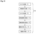
図1に示すように、「ウルトラキャパシタ10」の一の例示的実施形態を示す。この場合において、ウルトラキャパシタ10は、電気二重層キャパシタ(EDLC)である。EDLCは少なくとも1つの電極3を含む(2つの電極3が存在する場合等、いくつかの場合において、電極は、負極3および正極3とよんでよい)。ウルトラキャパシタ10内に取り付けるとき、各々の電極3は、電解質界面において電荷の二重層を提供する。いくつかの実施形態において、複数の電極3が含まれる。尤も、議論の目的のため、2つの電極3のみを示す。慣例通り、本明細書において電極3の少なくとも1つは、エネルギー貯蔵を提供するために炭素ベースのエネルギー貯蔵媒体1(本明細書において更に論じる)を使用する。
As shown in FIG. 1, an exemplary embodiment of the "
電極3の各々はそれぞれ、集電体2(「電荷収集体(charge collector)」ともよぶ)を含む。電極3は、セパレータ5によって離隔される。一般に、セパレータ5は、電極3を2以上の区画に離隔するのに用いられる薄型構造材料(通常はシート(または薄板))である。
Each of the
電解質6の少なくとも1つの形態は、電極3およびセパレータ5における空隙(void space)ならびに電極3とセパレータ5との間の空隙に含まれ、かつそれを満たす。一般に、電解質6は、電荷を帯びたイオンへと分離する物質である。いくつかの実施形態において、その物質を溶解する溶媒が含まれてよい。結果として得られる電解液は、イオン輸送により電気を通す。
At least one form of the electrolyte 6 is contained in and fills the void space in the
一般に、(1または複数の)電極3およびセパレータ5の組み合わせは、その後、巻かれた形状または角柱形の一方に成形され、次いで、円筒形または角柱形のハウジング7に詰められる。電解質6が加えられると、ハウジング7は密封される。種々の例において、パッケージは、レーザー、超音波および/または溶接技術を用いた技術によって密封される。ハウジング7(「封入体(enclosing body)」または「容器(またはケース、case)」または他の同様の用語でよぶ)は、少なくとも1つの端子8を含む。各端子8は、通常はエネルギー貯蔵媒体1に連結された導線(図示せず)を通じて、エネルギー貯蔵媒体1に貯蔵されるエネルギーへの電気的アクセスを提供する。
Generally, the combination of the (one or more)
即ち、いくつかの実施形態において、複数のリード線(図示せず)が、集電体2の各々に電気的に連結される。複数のリード線の各々は、(従ってウルトラキャパシタ10の極性に対して)まとめられてハウジング7の各々の端子8に連結される。
That is, in some embodiments, a plurality of lead wires (not shown) are electrically connected to each of the
例示的EDLCにおいて、エネルギー貯蔵媒体1はカーボンナノチューブから形成される。エネルギー貯蔵媒体1は、例えば活性炭、炭素繊維(またはカーボンファイバー)、レーヨン、グラフェン、エアロゲル、炭素布およびカーボンナノチューブの複数の形態を含む他の炭素質材料を含んでよい。活性炭電極は、例えば、炭素化合物の炭化により得られる炭素材料に第1の活性化処理を行うことにより炭素基材(base material)を製造し、炭素基材にバインダー(または結合剤)を加えることにより成形体を製造し、成形体を炭化し、最後に炭化した成形体に第2の活性化処理を行うことにより活性炭電極を製造することにより製造することができる。炭素繊維電極は、例えば、表面積の大きい炭素繊維を備える紙または布状の母材(またはプレフォーム)を用いることにより製造することができる。カーボンナノチューブの製造およびウルトラキャパシタ10におけるナノチューブの適用は、本明細書において更に詳細に論じられる。
In an exemplary EDLC, the
従って、いくつかの実施形態において、エネルギー貯蔵媒体1を形成するのに用いられる材料は、純炭素(および現在存在し得る又は後に考案され得る炭素の種々の形態)以外の材料を含んでよい。即ち、他の材料の種々の配合がエネルギー貯蔵媒体1に含まれてよい。より具体的には、かつ限定的でない例において、少なくとも1つのバインダー材料をエネルギー貯蔵媒体1において用いてよいが、(バインダー材料等の)他の材料の添加を勧める又は必要とするものではない。尤も、一般に、エネルギー貯蔵媒体1は実質的に炭素から形成され、従って、本明細書において「炭素質材料」、「炭素質層」および他の同様の用語でよんでよい。手短に言えば、エネルギー貯蔵媒体1は、主に炭素から形成されるが、エネルギー貯蔵媒体1として所望の機能性を提供するために、任意の形態の炭素(および適切である又は許容可能であると見なされる任意の添加剤または不純物)を含んでよい。
Thus, in some embodiments, the material used to form the
エネルギー貯蔵媒体1において用いるのに適した炭素質材料の種々の形態のいくつかの実施形態が、本明細書において例として提示される。以下に論じるこれらの実施形態はロバスト性のエネルギー貯蔵をもたらし、電極3において用いるのによく適している。これらの例は説明のためのものであり、エネルギー貯蔵媒体1において用いるのに適した炭素質材料の実施形態に限定されないことに留意すべきである。
Some embodiments of various forms of carbonaceous materials suitable for use in the
電解質6は、カチオン9およびアニオン11のペアを含み、溶媒を含んでよい。各々の種々の組み合わせを用いてよい。例示的EDLCにおいて、カチオン9は、1-(3-シアノプロピル)-3-メチルイミダゾリウム、1,2-ジメチル-3-プロピルイミダゾリウム、1,3-ビス(3-シアノプロピル)イミダゾリウム、1,3-ジエトキシイミダゾリウム、1-ブチル-1-メチルピペリジニウム、1-ブチル-2,3-ジメチルイミダゾリウム、1-ブチル-3-メチルイミダゾリウム、1-ブチル-4-メチルピリジニウム、1-ブチルピリジニウム、1-デシル-3-メチルイミダゾリウム、1-エチル-3-メチルイミダゾリウム、3-メチル-1-プロピルピリジニウムおよびこれらの組み合わせ並びに適切であると見なされる他の同等物の少なくとも1つを含んでよい。 The electrolyte 6 contains a pair of cations 9 and anions 11 and may contain a solvent. Various combinations of each may be used. In an exemplary EDLC, the cation 9 is 1- (3-cyanopropyl) -3-methylimidazolium, 1,2-dimethyl-3-propylimidazolium, 1,3-bis (3-cyanopropyl) imidazolium, 1,3-Diethoxyimidazolium, 1-butyl-1-methylpiperidinium, 1-butyl-2,3-dimethylimidazolium, 1-butyl-3-methylimidazolium, 1-butyl-4-methylpyridinium , 1-butylpyridinium, 1-decyl-3-methylimidazolium, 1-ethyl-3-methylimidazolium, 3-methyl-1-propylpyridinium and combinations thereof and other equivalents deemed appropriate. At least one may be included.
追加の例示的カチオン9は、イミダゾリウム、ピラジニウム、ピペリジニウム、ピリジニウム、ピリミジニウムおよびピロリジニウムを含む。概括的に、これらのカチオン9は、高い熱安定性、低いガラス転移温度(Tg)および高い伝導率を示すものとして選択され、広い温度範囲にわたって良好な電気的性能を示した。従って、所望の特性を示すカチオン9の他の実施形態を同様に使用してよく、または上述のいずれかと併せて使用してよい。 Additional exemplary cations 9 include imidazolium, pyridinium, piperidinium, pyridinium, pyridinium and pyrrolidinium. Overall, these cations 9 have been selected for high thermal stability, low glass transition temperature (Tg) and high conductivity and have shown good electrical performance over a wide temperature range. Therefore, other embodiments of cation 9 exhibiting the desired properties may be used in the same manner or in combination with any of the above.
例示的EDLCにおいて、アニオン11は、ビス(トリフルオロメタンスルホナート)イミド、トリス(トリフルオロメタンスルホナート)メチド、ジシアナミド、テトラフルオロボラート、ヘキサフルオロホスフェート、トリフルオロメタンスルホナート、ビス(ペンタフルオロエタンスルホナート)イミド、チオシアナート、トリフルオロ(トリフルオロメチル)ボレートおよびこれらの組み合わせ並びに適切であると見なされる他の同等物の少なくとも1つを含んでよい。 In an exemplary EDLC, the anion 11 is a bis (trifluoromethanesulfonate) imide, tris (trifluoromethanesulfonate) methide, dicyanamide, tetrafluoroborate, hexafluorophosphate, trifluoromethanesulfonate, bis (pentafluoroethanesulfonate). ) Imid, thiocyanate, trifluoro (trifluoromethyl) borate and combinations thereof and at least one of the other equivalents deemed appropriate.
溶媒は、アセトニトリル、アミド、ベンゾニトリル、ブチロラクトン、環状エーテル、ジブチルカーボナート、ジエチルカーボナート、ジエチルエーテル、ジメトキシエタン、ジメチルカーボナート、ジメチルホルムアミド、ジメチルスルホン、ジオキサン、ジオキソラン、ギ酸エチル、エチレンカーボナート、エチルメチルカーボナート、ラクトン、直鎖状エーテル、ギ酸メチル、メチルプロピオナート、メチルテトラヒドロフラン、ニトリル、ニトロベンゼン、ニトロメタン、n-メチルピロリドン、プロピレンカーボナート、スルホラン、スルホン、テトラヒドロフラン、テトラメチレンスルホン、チオフェン、エチレングリコール、ジエチレングリコール、トリエチレングリコール、ポリエチレングリコール、炭酸エステル、γ-ブチロラクトン、ニトリル、トリシアノヘキサン、これらのいずれかの組み合わせ、または適切な性能特性を示す他の(1または複数の)材料を含んでよい。 Solvents include acetonitrile, amide, benzonitrile, butyrolactone, cyclic ether, dibutyl carbonate, diethyl carbonate, diethyl ether, dimethoxyethane, dimethyl carbonate, dimethylformamide, dimethyl sulfone, dioxane, dioxolane, ethyl formate, ethylene carbonate, Ethylmethylcarbonate, lactone, linear ether, methyl formate, methylpropionate, methyl tetrahydrofuran, nitrile, nitrobenzene, nitromethane, n-methylpyrrolidone, propylene carbonate, sulfone, sulfone, tetrahydrofuran, tetramethylene sulfone, thiophene, Includes ethylene glycol, diethylene glycol, triethylene glycol, polyethylene glycol, carbonate, γ-butyrolactone, nitrile, tricyanohexane, any combination thereof, or other (s) materials exhibiting suitable performance characteristics. It's fine.
セパレータ5は不織ガラスから作製してよい。セパレータ5は、ガラス繊維、セラミック、およびDuPont Chemicals(デラウェア州ウィルミントン)によってTEFLON(登録商標)として一般に市販されているポリテトラフルオロエチレン(PTFE)等のフッ素ポリマーから作製してもよい。例えば、不織ガラスを用いることにより、セパレータ5は、主繊維(main fiber)およびバインダー繊維を含み得、バインダー繊維の各々は主繊維の各々の繊維径より小さい繊維径を有し、主繊維が一緒に結合するのを可能にする。
The
一般に、用語「電極」は、電気回路に組み込んでよいデバイスにおいて、多くの場合非金属である別の材料と接触させるのに用いられる電気伝導体を指す。エネルギー貯蔵媒体における例示的な第2の材料は、固体、液体および気体を含む種々の形態であってよい。エネルギー貯蔵媒体1の材料は、導電性材料、半導体、電解質等を含んでよい。一般に、用語「電極」は、本明細書において用いる場合、エネルギー貯蔵媒体1、および所望の機能性をもたらすためにエネルギー貯蔵媒体1に伴われてよい追加の構成要素(例えばエネルギー貯蔵媒体1と一体になる集電体2)に関する。
In general, the term "electrode" refers to an electrical conductor used to contact another material, which is often non-metal, in a device that may be incorporated into an electrical circuit. An exemplary second material in an energy storage medium may be in various forms, including solids, liquids and gases. The material of the
ここで図2~5を参照して、カーボンナノチューブ(CNT)を製造するための方法および装置の態様を示す。開示される技術は、製造プロセスにわたって高度な制御を提供し、それにより、ウルトラキャパシタ10における使用等の特定の用途に十分に適合され得る(即ち特定の用途のために設計され得る)CNTがもたらされる。概要としては、基材が提供される。次いで、触媒材料を基材上に配置し、炭素質材料を触媒の上に沈積させる。実質的に酸素のない環境において製造を行う場合、酸化に伴う問題および還元の必要性が回避される。技術の種々の態様を実施する場合、CNTの製造者は、高品質のCNTを製造するための効果的な方法を理解するだろう。
Here, with reference to FIGS. 2 to 5, embodiments of methods and devices for producing carbon nanotubes (CNTs) are shown. The disclosed technology provides a high degree of control over the manufacturing process, thereby providing CNTs that can be well adapted (ie, designed for a particular application) for a particular application such as use in an
本明細書に開示される技術は、所望の特性を有するCNTを提供するために必要に応じて調節されてよい。即ち、方法は、例えば密度、表面積、長さ、壁の数、組成(即ち金属または非金属)、端部の特性(即ち開放端(またはオープンエンド)または閉端(またはクローズドエンド))等の好都合な特性を考慮して制御してよい。 The techniques disclosed herein may be adjusted as necessary to provide CNTs with the desired properties. That is, the method may include, for example, density, surface area, length, number of walls, composition (ie metal or non-metal), end characteristics (ie open end (or open end) or closed end (or closed end)), etc. It may be controlled in consideration of favorable characteristics.
例示的実施形態の概説のために図2を参照してよい。図2において、CNTの製造120のための方法の限定的でない態様が提示される。この実施形態において、製造120のための方法は、基材が製作機(「製造装置」および他の同様の用語でもよぶ)の中に装着される第1の工程(基材の装着121)を含む。第2の工程において、触媒の層が基材に適用される(触媒の適用122)。第3の工程において、炭素質材料が触媒の上に徐々に沈積してCNTが成長する(炭素の沈積123、「沈積工程」、「成長工程」または他の同様の用語でもよばれる)。第4の工程において、取り外し及び後続の使用のためにCNTを冷却する(CNT冷却124)。いくつかの実施形態において、本明細書において更に論じるように、緩衝(またはバッファ、buffer)工程125が同様に含まれる。
FIG. 2 may be referred to for an overview of exemplary embodiments. FIG. 2 presents a non-limiting aspect of the method for the production of
CNTの大量生産のための例示的装置の態様が提供される。種々の実施形態において、装置は、厳密な環境制御(例えば温度、雰囲気の含有量(atmospheric content)および/または圧力等の制御)をもたらすように配置(または構成)される。いくつかの実施形態において、CNT製品は、継続的(即ち中断のない又は連続的)プロセスにおいて製造される。プロセス全体にわたって製造環境を制御することにより、また、プロセスの間に必要に応じて製造環境の態様を変化させることにより、所望の特性を示すCNTを製造することが可能である。 An exemplary device aspect for mass production of CNTs is provided. In various embodiments, the device is arranged (or configured) to provide strict environmental control (eg, control of temperature, atmospheric content and / or pressure, etc.). In some embodiments, the CNT product is manufactured in a continuous (i.e., uninterrupted or continuous) process. It is possible to produce CNTs exhibiting the desired characteristics by controlling the production environment throughout the process and by changing the mode of the production environment as needed during the process.
想像されるように、方法は多数の機器および制御を必要とし、従って、これらの4つの工程の説明は過度に単純化されている。製造120のための方法における各工程をより十分に説明するためのいくつかの状況(または前後関係)および追加の実施形態を提示するために、いくつかの定義、パラメータ、特性等を示す。 As you can imagine, the method requires a large number of equipment and controls, so the description of these four steps is oversimplified. Some definitions, parameters, properties, etc. are presented to present some context (or context) and additional embodiments to better illustrate each step in the method for manufacturing 120.
「製造装置」、「製作機」または他の同様の(1または複数の)用語のいずれかでよばれる機械は通常、必要に応じて、またはCNTの作製の要求に従って構成要素(または部品)を含む。製造装置に含まれる例示的構成要素は、記載される機能を必要に応じて果たす構成要素を含む。含まれてよい例示的かつ限定的でない例としては、少なくとも1つのポンプ、バルブ、電線管、ガス管、電力供給装置(または電源)、ガス供給装置(不活性ガス、炭素質ガス等の供給装置を含む)、水供給装置、ノズル、取り入れ口、出口、通気孔(vent)、排気装置(exhaust)、ファン、材料移動装置(例えばコンベヤベルト、駆動システム等)、加熱要素(抵抗加熱要素等)、熱交換器(または他の形態の冷却)、シャッター、ドア、サーボモーター(または自動制御装置、servo)、モーター、センサー(電気、温度、圧力、ガス、光学等)、変換器(またはトランスデューサ)、制御装置(またはコントローラ)、ヒューマンインターフェース、コンピュータインターフェース、処理装置(またはプロセッサ)、データ記憶装置、メモリー、バス、機械の操作を管理するためのコンピュータ実行可能コード、および機械のオペレータ、製造者または設計者により必要とされ得る他の構成要素が挙げられる。手短に言えば、本明細書に記載の方法を支援し且つ可能にする種々の科学技術が周知であると考えられ、概括的には本明細書に開示される発明の一部ではない。従って、本明細書における教示事項を実施するための機器の種々の実施形態および変形を考えると、そのような機器の議論は、概括的にはCNT集合体の発生に影響を及ぼし得るいくつかの態様に限定される。 Machines referred to by any of the terms "manufacturing equipment", "manufacturing machine" or other similar (s) terms usually include components (or parts) as needed or as required to make CNTs. include. Exemplary components included in the manufacturing equipment include components that perform the described functions as needed. Exemplary and non-limiting examples that may be included are at least one pump, valve, wire tube, gas tube, power supply (or power supply), gas supply (inert gas, carbonaceous gas, etc. supply). (Including), water supply equipment, nozzles, intakes, outlets, vents, exhaust equipment (exhaust), fans, material transfer equipment (eg conveyor belts, drive systems, etc.), heating elements (resistance heating elements, etc.) , Heat exchangers (or other forms of cooling), shutters, doors, servo motors (or automated controllers, servos), motors, sensors (electricity, temperature, pressure, gas, optics, etc.), converters (or transducers) , Control (or controller), human interface, computer interface, processor (or processor), data storage, memory, bus, computer executable code to manage machine operations, and machine operators, manufacturers or There are other components that may be needed by the designer. Briefly, various scientific techniques that support and enable the methods described herein are believed to be well known and are not generally part of the invention disclosed herein. Thus, given the various embodiments and variations of the equipment for carrying out the teachings herein, the discussion of such equipment is generally some that can affect the generation of CNT aggregates. Limited to aspects.
本明細書において用いられる場合、「配列されたCNT集合体」、「CNT集合体」、「垂直に配列されたカーボンナノチューブ、VCNT」および同様の用語は通常、多数のCNTが共通の方法で配列または配向している構造体を指す。いくつかの実施形態において、配列されたCNT集合体の比表面積SAは300m2/g以上である(例えばCNTの大部分が閉じている場合)。他の実施形態において、表面積SAは1,300m2/g以上である(例えばCNTの大部分が開いている場合)。「CNTの集合体」は通常、複数の垂直に配列されたCNT構造体を指す。いくつかの実施形態において、重量密度(ρw)は0.002g/cm3~0.2g/cm3の範囲である。一般に、本明細書において論じられるCNTの実施形態は、垂直に配列されたカーボンナノチューブ、VCNTに関する。尤も、CNTが炭素の他のナノフォームと混合される実施形態等のいくつかの実施形態において、このことは必要条件ではなく、あるいは事実ですらない。 As used herein, "arranged CNT aggregates", "CNT aggregates", "vertically arranged carbon nanotubes, VCNTs" and similar terms are usually used by a large number of CNTs in a common manner. Or refers to an oriented structure. In some embodiments, the specific surface area SA of the arranged CNT aggregates is 300 m 2 / g or more (eg, when most of the CNTs are closed). In other embodiments, the surface area SA is at least 1,300 m 2 / g (eg, when most of the CNTs are open). "Aggregate of CNTs" usually refers to a plurality of vertically arranged CNT structures. In some embodiments, the weight density (ρ w ) is in the range of 0.002 g / cm 3 to 0.2 g / cm 3 . In general, embodiments of CNTs discussed herein relate to vertically arranged carbon nanotubes, VCNTs. However, in some embodiments, such as embodiments where CNTs are mixed with other nanoforms of carbon, this is not a requirement or a fact.
ナノチューブおよび他のナノ構造体に関する用語「垂直に配列された」は一般に、製造時におけるナノチューブの配向に関することを認識すべきである。尤も、この専門用語は限定的であることを意味しない。即ち、「垂直に配列されたナノチューブ」の集合体を考える場合、用語「垂直」は重要でないことがあり、あるいは誤解を招くおそれがあり得ることを認識すべきである。従って、本明細書において論じられるように、「垂直に配列されたナノチューブ」の集合体および他の形態は一般に、実質的に平行な、繰り返しの又は組織的な構造を含む集合体を指すことを認識すべきである。 It should be recognized that the term "vertically arranged" for nanotubes and other nanostructures generally relates to the orientation of nanotubes during manufacture. However, this terminology does not mean that it is limited. That is, it should be recognized that the term "vertical" may not be important or may be misleading when considering an aggregate of "vertically arranged nanotubes". Thus, as discussed herein, aggregates and other forms of "vertically arranged nanotubes" generally refer to aggregates containing substantially parallel, repetitive or organized structures. You should be aware.
CNT集合体が共通の配向および大きい比表面積SAを示すためには、CNT集合体の高さは、10μm以上1cm以下の範囲であってよい。一般に、高さが10μm以上であることにより、配向が向上する。別法として、高さが1cm以下であると、そのような高さは急速な成長を可能にし、従って炭素質不純物の付着が制御されるので、比表面積SAを向上させることができる。 In order for the CNT aggregate to exhibit a common orientation and a large specific surface area SA, the height of the CNT aggregate may be in the range of 10 μm or more and 1 cm or less. Generally, when the height is 10 μm or more, the orientation is improved. Alternatively, when the height is 1 cm or less, such height allows rapid growth and thus controls the adhesion of carbonaceous impurities, so that the specific surface area SA can be improved.
種々の実施形態において、カーボンナノチューブは通常、特定の特性を示す。とりわけ、いくつかの実施形態において、製造されるカーボンナノチューブは、約50μm~約5mmの長さ(またはそれより長い長さ)を示す。いくつかの実施形態において、カーボンナノチューブは約200μm~約2mmである。いくつかの実施形態において、カーボンナノチューブは、例えば1~10の壁を含んでよい。いくつかの実施形態において、例えば1~5の壁を含んでよい。カーボンナノチューブは、例えば約0.7nm~10nmの径を有してよい。垂直に配列されたカーボンナノチューブのアレイ(または配列、array)として考えた場合、密度は約103CNT/cm2~約1013CNT/cm2であってよい。いくつかの実施形態において、密度は約1011CNT/cm2~約1012CNT/cm2であってよい。 In various embodiments, carbon nanotubes usually exhibit certain properties. In particular, in some embodiments, the carbon nanotubes produced exhibit a length of about 50 μm to about 5 mm (or longer). In some embodiments, the carbon nanotubes are from about 200 μm to about 2 mm. In some embodiments, the carbon nanotubes may include, for example, 1-10 walls. In some embodiments, it may include, for example, 1-5 walls. The carbon nanotubes may have a diameter of, for example, about 0.7 nm to 10 nm. When considered as an array (or array, array) of vertically arranged carbon nanotubes, the density may be from about 103 CNT / cm 2 to about 1013 CNT / cm 2 . In some embodiments, the density may be from about 1011 CNT / cm 2 to about 1012 CNT / cm 2 .
電極3において用いられるカーボンナノチューブは、特定の特性が実現されるように処理してよく、さもなければ加工してよい。電極に含まれる場合におけるカーボンナノチューブの例示的特性および物理的特性としては、約30μm~500μm、いくつかの場合において約100μm~約200μmの活物質の厚さ;約0.3g/cm3~約0.8g/cm3、いくつかの場合において約0.5g/cm3~約0.6g/cm3の体積密度が挙げられる。一般に、カーボンナノチューブはいずれの種類のバインダーも含まない。エネルギー貯蔵媒体は、垂直に配列されたカーボンナノチューブ、もつれた(entangled)カーボンナノチューブ、他の形態の炭素、および適切であると見なされる材料のいずれかの組み合わせを含んでよい。一般に、カーボンナノチューブは、約500m2/g~約2,200m2/gの表面積SAを示す(これは、CNTの壁に穴(hole)および/または細孔(pore)が形成された結果としての、処理されていないCNTの表面積の増大であってよい)。エネルギー貯蔵媒体として成形した場合、カーボンナノチューブは、約10:1~約100:1の圧縮率(垂直に配列された場合)を有してよい。
The carbon nanotubes used in the
従って、ウルトラキャパシタ10において用いられる場合、本明細書に記載のカーボンナノチューブを用いた電極3は特定の好都合な特性も示してよい。例えば、ウルトラキャパシタ10の性能は、(最大作動電圧において)約100F/g~約200F/gの質量比容量;(最大作動電圧において)約50F/cc~約100F/ccの体積比容量;約3V~4.5Vの最大作動電圧を含んでよい。例えば、ウルトラキャパシタ10は、約0.5Ω/cm2~約1Ω/cm2の等価直列抵抗(ESR)を示してよい。
Therefore, when used in an
用語「基材」は一般に、カーボンナノチューブのための触媒を表面に担持することができる部材であって、高温(例えば400℃以上の温度)であってもその形状を保持し得る部材を指す。CNTの製造に使用可能であることが証明されている任意の種類の基材を用いてよい。材料の限定的でない例としては、以下のものを含む:鉄、ニッケル、クロム、モリブデン、タングステン、チタン、アルミニウム、マンガン、コバルト、銅、銀、金、白金、ニオブ、タンタル、鉛、亜鉛、ガリウム、ゲルマニウム、ヒ素、インジウム、蛍光物質(phosphor)およびアンチモン等の金属;これらの材料または他の適切な材料を含む合金および酸化物;シリコン、石英、ガラス、雲母、黒鉛およびダイヤモンド等の非金属;ならびにセラミック。一般に、一般に、金属材料は、シリコンおよびセラミックよりもコストが低い。特に、Fe-Cr(鉄-クロム)合金、Fe-Ni(鉄-ニッケル)合金、Fe-Cr-Ni(鉄-クロム-ニッケル)合金等が適している。基材は、薄膜、ブロック(または塊)または粉末および平板の形状をとってよい。尤も、特に、基材がその体積に対して大きい表面積を有するような形状が大量生産に好都合である。 The term "base material" generally refers to a member that can support a catalyst for carbon nanotubes on its surface and that can retain its shape even at high temperatures (eg, temperatures above 400 ° C.). Any type of substrate that has been proven to be usable in the manufacture of CNTs may be used. Non-limiting examples of materials include: iron, nickel, chromium, molybdenum, tungsten, titanium, aluminum, manganese, cobalt, copper, silver, gold, platinum, niobium, tantalum, lead, zinc, gallium. Metals such as germanium, arsenic, indium, phosphor and antimony; alloys and oxides containing these or other suitable materials; non-metals such as silicon, quartz, glass, mica, graphite and diamond; As well as ceramic. In general, metallic materials are generally less costly than silicon and ceramics. In particular, Fe—Cr (iron-chromium) alloys, Fe—Ni (iron-nickel) alloys, Fe—Cr—Ni (iron-chromium-nickel) alloys and the like are suitable. The substrate may be in the form of a thin film, block (or mass) or powder and flat plate. However, in particular, a shape in which the base material has a large surface area with respect to its volume is convenient for mass production.
用語「浸炭防止層」は一般に、基材上の層を指す。基材は、その前面または裏面のいずれかに形成された浸炭防止層を有してよい。いくつかの実施形態において、基材は、その前面および裏面の各々に形成された浸炭防止層を含む。形成は、例えばスパッタリング等の技術によって実現されてよい。浸炭防止層は一般に、基材が浸炭して、それによりカーボンナノチューブを発生させる工程において変形するのを防止するための保護層である。浸炭防止層は厚さが様々であってよい。種々の実施形態において、浸炭防止層の厚さは約1nm~約500nmであり、いくつかの場合において約5nm~約100nmである。 The term "carburizing prevention layer" generally refers to a layer on a substrate. The substrate may have a carburizing prevention layer formed on either the front surface or the back surface thereof. In some embodiments, the substrate comprises a carburizing prevention layer formed on each of its front and back surfaces. The formation may be realized by a technique such as sputtering. The carburizing prevention layer is generally a protective layer for preventing the base material from carburizing and thereby deforming in the process of generating carbon nanotubes. The carburizing prevention layer may have various thicknesses. In various embodiments, the thickness of the carburizing prevention layer is from about 1 nm to about 500 nm, and in some cases from about 5 nm to about 100 nm.
いくつかの実施形態において、浸炭防止層は金属またはセラミック材料から構成される(セラミック材料は浸炭を防止するのに効果的である)。適切な金属の例として、銅およびアルミニウムが挙げられる。適切なセラミック材料の例としては、以下のものが挙げられる:酸化アルミニウム、酸化ケイ素、酸化ジルコニウム、酸化マグネシウム、酸化チタン、シリカ、アルミナ、酸化クロム、酸化ホウ素、酸化カルシウムおよび酸化亜鉛等の酸化物;ならびに窒化アルミニウムおよび窒化ケイ素等の窒化物。なお、酸化アルミニウムおよび酸化ケイ素は共に、浸炭を防止するのに非常に効果的である。 In some embodiments, the carburizing prevention layer is composed of a metal or ceramic material (ceramic material is effective in preventing carburizing). Examples of suitable metals include copper and aluminum. Examples of suitable ceramic materials include: aluminum oxide, silicon oxide, zirconium oxide, magnesium oxide, titanium oxide, silica, alumina, chromium oxide, boron oxide, calcium oxide and oxides such as zinc oxide. ; And nitrides such as aluminum nitride and silicon nitride. Both aluminum oxide and silicon oxide are very effective in preventing carburizing.
本明細書において用いられる場合、「触媒」は、基材または浸炭防止層に設けられてよい。CNT製造において使用可能であることが証明されている任意の種類の触媒を用いることができる。触媒の限定的でない例としては、鉄、ニッケル、コバルト、モリブデン、これらの塩化物、これらの合金、ならびにこれらとアルミニウム、アルミナ、チタニア、窒化チタンまたは酸化ケイ素との複合体または層が挙げられる。他の限定的でない例としては、鉄-モリブデン薄膜、アルミナ-鉄薄膜、アルミナ-コバルト薄膜、アルミナ-鉄-モリブデン薄膜、アルミニウム-鉄薄膜およびアルミニウム-鉄-モリブデン薄膜が挙げられる。触媒は、CNT製造に使用可能であることが証明されている量の範囲において用いることができる。例えば、鉄を用いるいくつかの実施形態において、形成される薄膜(またはフィルム)の厚さは0.1nm以上~100nm以下の範囲であってよい。いくつかの他の実施形態において、鉄の厚さは0.5nm以上~5nm以下であってよい。いくつかの更なる実施形態において、鉄の厚さは0.8nm~2nm以下であってよい。 As used herein, the "catalyst" may be provided on a substrate or anti-carburizing layer. Any type of catalyst that has been proven to be usable in CNT production can be used. Non-limiting examples of catalysts include iron, nickel, cobalt, molybdenum, chlorides thereof, alloys thereof, and composites or layers of these with aluminum, alumina, titania, titanium nitride or silicon oxide. Other non-limiting examples include iron-molybdenum thin films, alumina-iron thin films, alumina-cobalt thin films, alumina-iron-molybdenum thin films, aluminum-iron thin films and aluminum-iron-molybdenum thin films. The catalyst can be used in an amount range that has been proven to be usable for CNT production. For example, in some embodiments using iron, the thickness of the thin film (or film) formed may be in the range of 0.1 nm or more and 100 nm or less. In some other embodiments, the thickness of iron may be 0.5 nm or more and 5 nm or less. In some further embodiments, the thickness of iron may be 0.8 nm to 2 nm or less.
触媒は複数の層を含んでよい。触媒は、基材の層または浸炭防止層等のもう1つの(または別の)層にわたって連続的であってよく、あるいは少なくとも部分的に非連続的であってよい。いくつかの実施形態において、追加の浸炭防止層等のもう1つの層は、触媒の表面に配置されてよい。いくつかの実施形態において、触媒は、酸化物等の別の材料の表面に沈積した金属を含んでよい。沈積は、「クラスター」または非連続な層をもたらす。本明細書において用いられる場合、用語「連続的」は一般に、下層の材料の「濡れ」または実質的に全面的な被覆を指す。 The catalyst may include multiple layers. The catalyst may be continuous (or another) over another layer, such as a layer of substrate or an anti-carburizing layer, or at least partially discontinuous. In some embodiments, another layer, such as an additional anti-carburizing layer, may be placed on the surface of the catalyst. In some embodiments, the catalyst may include a metal deposited on the surface of another material, such as an oxide. Sedimentation results in "clusters" or discontinuous layers. As used herein, the term "continuous" generally refers to the "wetting" or substantially total coverage of the underlying material.
基材の表面への触媒の形成に乾式法を適用することが可能である。例えば、スパッタリング蒸発(sputtering evaporation)法を用いてよい。カソードアーク(cathodic arc)蒸着、スパッタ蒸着、イオンビーム支援蒸着、イオンビーム誘起蒸着およびエレクトロスプレーイオン化のいずれかの1以上等の他の技術を必要に応じて用いてよい。更に、周知のフォトリソグラフィ、ナノプリント(nanoprinting)等の適用により得られるパターニングを併用して触媒を任意の形状に成形することが可能である。 It is possible to apply the dry method to the formation of a catalyst on the surface of the substrate. For example, a sputtering evaporation method may be used. Other techniques such as one or more of cathode arc deposition, spatter vapor deposition, ion beam assisted deposition, ion beam induced vapor deposition and electrospray ionization may be used as needed. Further, it is possible to form the catalyst into an arbitrary shape by using the patterning obtained by applying well-known photolithography, nanoprinting, or the like in combination.
一の実施形態において、配列されたCNT集合体の形状を適宜制御することが可能である。このことは、例えば、基体に形成された触媒のパターニングおよびCNTの成長時間の制御に応じて達成され得る。その結果、配列されたCNT集合体は、薄膜形状、円筒形、角柱形または他の複雑な形状のいずれかをとる。特に、薄膜の形状において、配列されたCNT集合体は、その長さ及び幅と比較して非常に小さい厚さ(高さ)を有する;尤も、長さ及び幅は、触媒のパターニングに応じて適宜制御することができ、配列されたCNT集合体を構成するCNTの成長時間に応じて適宜制御することができる。いくつかの実施形態において、触媒の形態は、例えば、触媒における粒子サイズを変化または制御し、それにより触媒上に成長するCNTの径の調節をもたらすことにより適合される。 In one embodiment, it is possible to appropriately control the shape of the arranged CNT aggregates. This can be achieved, for example, depending on the patterning of the catalyst formed on the substrate and the control of the growth time of the CNTs. As a result, the arranged CNT aggregates can take either a thin film shape, a cylindrical shape, a prismatic shape or another complex shape. Especially in the shape of the thin film, the arranged CNT aggregates have a very small thickness (height) relative to their length and width; however, the length and width depend on the patterning of the catalyst. It can be appropriately controlled, and can be appropriately controlled according to the growth time of the CNTs constituting the arranged CNT aggregate. In some embodiments, the form of the catalyst is adapted, for example, by varying or controlling the particle size in the catalyst, thereby resulting in adjustment of the diameter of the CNTs growing on the catalyst.
一般に、「還元ガス」は本明細書の教示事項により必要とされていない。還元ガスは、触媒の還元をもたらすのに従来技術において通常用いられる。還元ガスは、成長温度において気体状態である任意の材料を含んでよい。還元ガスは、CNTの成長に適した微粒子になるため及び触媒の活性を向上させるために触媒を刺激するのに用いてもよい。還元ガスの一例は、水素ガス、アンモニウム、水蒸気またはそれらの混合物等の還元能力を有するガスである。還元ガスは一般に酸化を克服するのに用いられるが、本明細書において開示される方法は、実質的に酸化がない(または酸化を含まない)。 In general, "reducing gas" is not required by the teachings herein. The reducing gas is commonly used in the prior art to bring about the reduction of the catalyst. The reducing gas may include any material that is in a gaseous state at the growth temperature. The reducing gas may be used to stimulate the catalyst in order to obtain fine particles suitable for the growth of CNTs and to improve the activity of the catalyst. An example of a reducing gas is a gas having a reducing ability such as hydrogen gas, ammonium, water vapor or a mixture thereof. Although reducing gases are commonly used to overcome oxidation, the methods disclosed herein are substantially free of (or free of) oxidation.
「原材料ガス」は一般に、CNTを発生させるために原材料(即ち炭素質材料)を供給するのに用いられる。CNT製造に使用可能であることが証明されている任意の種類の原材料を用いることができる。一般に、成長温度において気体状である原料炭素源が使用可能である。中でも、メタン、エタン、エチレン、プロパン、ブタン、ペンタン、ヘキサン、ヘプタンプロピレンおよびアセチレン等の炭化水素が適している。加えて、メタノールおよびエタノール等の低級アルコール、アセトン、一酸化炭素等の低炭素の酸素含有化合物、ならびにこれらの混合物が使用可能である。更に、原材料ガスは不活性ガスで希釈してよい。 "Raw material gas" is commonly used to supply raw materials (ie, carbonaceous materials) to generate CNTs. Any kind of raw material that has been proven to be usable for CNT production can be used. Generally, a raw material carbon source that is gaseous at the growth temperature can be used. Among them, hydrocarbons such as methane, ethane, ethylene, propane, butane, pentane, hexane, heptane propylene and acetylene are suitable. In addition, lower alcohols such as methanol and ethanol, low carbon oxygen-containing compounds such as acetone and carbon monoxide, and mixtures thereof can be used. Further, the raw material gas may be diluted with an inert gas.
一般に、「不活性ガス」は、製造プロセスにおいて含まれてよいガスであり、CNTが成長する温度において不活性であるガスであることのみが必要とされる。一般に、「不活性」は、CNTの成長と実質的に反応しないガスの特性であると考えられる。CNT製造に使用可能であることが証明されている任意の種類の不活性ガスを使用することができる。不活性ガスの限定的でない例は、ヘリウム、アルゴン、水素、窒素、ネオン、クリプトン、二酸化炭素、塩素およびこれらの混合物である。 In general, the "inert gas" is a gas that may be included in the manufacturing process and only needs to be a gas that is inert at the temperature at which the CNTs grow. Generally, "inactivity" is considered to be a property of the gas that does not substantially react with the growth of CNTs. Any type of inert gas that has been proven to be usable for CNT production can be used. Non-limiting examples of inert gases are helium, argon, hydrogen, nitrogen, neon, krypton, carbon dioxide, chlorine and mixtures thereof.
「触媒活性化材料」を種々の実施形態において用いてよい。触媒活性化材料の添加により、カーボンナノチューブ製造における効率およびカーボンナノチューブの純度を向上させることができる。一般に、触媒活性化材料は、CNTを成長温度において実質的に損傷しない酸素含有物質として特徴付けられてよい。従って、いくつかの点において、この実施形態は「実質的に酸素のない環境」であると考えてよい。水以外の有効な例として以下のものが挙げられる:硫化水素、酸素、オゾン、酸性ガス、窒素酸化物、一酸化炭素および二酸化炭素等の低炭素の酸素含有化合物;エタノールおよびメタノール等のアルコール;テトラヒドロフラン等のエーテル;アセトン等のケトン;アルデヒド;エステル;窒素酸化物;およびこれらの混合物。 The "catalytically activating material" may be used in various embodiments. The addition of the catalytically activating material can improve the efficiency and purity of the carbon nanotubes in the production of carbon nanotubes. In general, the catalytically activating material may be characterized as an oxygen-containing material that does not substantially damage the CNTs at growth temperature. Therefore, in some respects, this embodiment may be considered a "substantially oxygen-free environment". Effective examples other than water include: low carbon oxygen-containing compounds such as hydrogen sulfide, oxygen, ozone, acid gas, nitrogen oxides, carbon monoxide and carbon dioxide; alcohols such as ethanol and methanol; Ethers such as tetrahydrofuran; Ketones such as acetone; aldehydes; esters; nitrogen oxides; and mixtures thereof.
一般に、触媒活性化材料は少量加えることのみが必要とされるが、加えるべき量に特定の限定は存在しない。一例として、いくつかの実施形態において、触媒活性化材料が水である場合、触媒活性化材料は、約10ppmから約10,000ppm以下の範囲、これらの実施形態のいくつかにおいて50ppm以上1,000ppm以下の量、およびこれらの実施形態のいくつかにおいて100ppm以上700ppm以下の量が加えられる。
Generally, the catalytically activating material only needs to be added in small amounts, but there is no particular limitation on the amount to be added. As an example, in some embodiments, when the catalytically activating material is water, the catalytically activating material ranges from about 10 ppm to about 10,000 ppm or less, and in some of these
触媒活性化材料を加えることにより、触媒の活性が強化され、触媒の寿命が延びる。触媒活性化材料を加える場合、CNTの成長はより長時間継続し、成長速度が同様に増大する。結果として、高さが著しく増大したCNT集合体が得られる。 By adding the catalyst activating material, the activity of the catalyst is enhanced and the life of the catalyst is extended. When the catalytically activating material is added, the growth of CNTs will continue for a longer period of time and the growth rate will increase as well. The result is a CNT aggregate with a significantly increased height.
「高炭素濃度の環境」は、全流量(または流れ)に対する原料ガスの割合が約2%~約20%である成長雰囲気を指す。これは一般に、過剰の炭素が存在する環境を指し、この環境はCNT集合体の効率の低い成長をもたらし得る。即ち、例えば、高炭素濃度の環境は、触媒の失活を含み得る。 "Environment with high carbon concentration" refers to a growth atmosphere in which the ratio of raw material gas to the total flow rate (or flow) is about 2% to about 20%. This generally refers to an environment in which excess carbon is present, which can result in inefficient growth of CNT aggregates. That is, for example, a high carbon concentration environment may include catalyst deactivation.
触媒の活性は触媒活性化材料によって向上するので、触媒の活性は、炭素濃度が高いいくつかの環境においてさえ持続するだろう。従って、CNTの成長速度はかなり向上し得る。 Since the activity of the catalyst is enhanced by the catalyst activating material, the activity of the catalyst will be sustained even in some environments with high carbon concentration. Therefore, the growth rate of CNTs can be significantly improved.
炉内圧力に関しては、種々の実施形態において、炉内圧力は102Pa以上であり且つ107Pa以下(100気圧)である。いくつかの実施形態において、炉内圧力は104Pa以上であり且つ3×10⁵Pa以下(3気圧)である。 Regarding the pressure inside the furnace, in various embodiments, the pressure inside the furnace is 102 Pa or more and 107 Pa or less (100 atm). In some embodiments, the pressure in the furnace is 104 Pa or more and 3 × 10 5 Pa or less (3 atm).
CNTが合成される反応温度は、金属触媒の特性、原料の炭素源および炉内圧力等の種々のパラメータを考慮して決定してよい。触媒活性化材料を使用する実施形態において、反応温度は一般に、触媒活性化材料が適切にはたらくような温度範囲に設定される。 The reaction temperature at which CNTs are synthesized may be determined in consideration of various parameters such as the characteristics of the metal catalyst, the carbon source of the raw material, and the pressure inside the furnace. In embodiments where the catalytically activating material is used, the reaction temperature is generally set to a temperature range in which the catalytically activating material works appropriately.
特に、触媒活性化材料として水を使用する場合において、反応温度は400℃~1,000℃であることが好ましい。400℃以下において、触媒活性化材料はその効果を発現しない。1,000℃以上において、触媒活性化材料はCNTと反応し得る。 In particular, when water is used as the catalyst activating material, the reaction temperature is preferably 400 ° C to 1,000 ° C. Below 400 ° C., the catalytically activating material does not exhibit its effect. Above 1,000 ° C., the catalytically activating material can react with CNTs.
別法として、触媒活性化材料として二酸化炭素を用いる場合、反応温度は約400℃~約1,100℃であることが好ましい。一般に、400℃以下の温度において、触媒活性化材料はその効果を発現しない。1,100℃以上において、触媒活性化材料はCNTと反応する。 Alternatively, when carbon dioxide is used as the catalyst activating material, the reaction temperature is preferably from about 400 ° C to about 1,100 ° C. Generally, at temperatures below 400 ° C., the catalytically activating material does not exhibit its effect. At 1,100 ° C. and above, the catalytically activating material reacts with CNTs.
本明細書において用いられる場合、用語「成長工程」、「沈積工程」および他の同様の用語は、CNT集合体の合成プロセスを指す。この工程は一般に、原材料ガス等の炭素質成分を含む、触媒の周りの環境を提供すること、ならびに環境、原材料ガスおよび触媒の少なくとも1つを加熱することを含む。これによりCNT集合体がもたらされる。 As used herein, the terms "growth step", "deposition step" and other similar terms refer to the process of synthesizing CNT aggregates. This step generally involves providing an environment around the catalyst, including carbonaceous components such as raw material gas, and heating at least one of the environment, raw material gas and catalyst. This results in a CNT aggregate.
本明細書において用いられる場合、「冷却工程」(「CNTの冷却124」および他の同様の用語でもよぶ)は一般に、CNT集合体、触媒および基材を冷却する工程を指す。いくつかの実施形態において、冷却工程は不活性ガスの存在下で行われる。即ち、成長工程の後、CNT集合体、触媒および基材は高温であり、酸素の存在下におかれるとそれ自体が酸化されるだろう。酸化は、酸化プロセスが実質的に制限される温度にCNT集合体、触媒および基材を冷却することにより実質的に防止される。いくつかの例において、冷却の停止は約200℃以下の温度である。 As used herein, "cooling step" (also referred to as "CNT cooling 124" and other similar terms) generally refers to the step of cooling a CNT aggregate, catalyst and substrate. In some embodiments, the cooling step is performed in the presence of an inert gas. That is, after the growth step, the CNT aggregates, catalysts and substrates are hot and will oxidize themselves in the presence of oxygen. Oxidation is substantially prevented by cooling the CNT aggregate, catalyst and substrate to a temperature at which the oxidation process is substantially restricted. In some examples, the cooling stop is at a temperature below about 200 ° C.
「装着部」は一般に、外気が製造装置に流れ込むのを防止するための一連のデバイスを含む。即ち、操作において、装着部は、基材を装着するための構成要素を備える。一般に、基材は搬送デバイスに装着される。一旦装着されると、酸素が(負圧排気および不活性ガスによる加圧の少なくとも一方により)装着部から放出される。いくつかの実施形態において、装着部は、ガスカーテン、ドア、シャッターまたは他のそのようなデバイスの少なくとも1つによって隔離される。 The "mounting portion" generally includes a set of devices for preventing outside air from flowing into the manufacturing equipment. That is, in operation, the mounting portion includes components for mounting the base material. Generally, the substrate is attached to the transport device. Once mounted, oxygen is released from the mounting (by at least one of negative pressure exhaust and pressurization with an inert gas). In some embodiments, the attachment is isolated by at least one of a gas curtain, door, shutter or other such device.
環境制御が装着部において確立されると(即ち、装着部が実質的に又は十分に酸素のない状態になると)、基材は、触媒の適用122を完了させるために触媒適用部へと進められる。装着部と同様に、製造装置の触媒適用部は環境制御に付される(即ち、実質的に又は十分に酸素のない状態である)。基材が触媒適用部に配置されると、触媒が基材に適用される。触媒を適用するための一の実施形態は、基材に触媒をスパッタリングすることを含む。 Once environmental control is established at the mounting site (ie, when the mounting site is substantially or sufficiently oxygen-free), the substrate is advanced to the catalyst application section to complete the catalyst application 122. .. Like the mounting part, the catalyst application part of the manufacturing equipment is subject to environmental control (ie, virtually or sufficiently oxygen-free). When the substrate is placed in the catalyst application section, the catalyst is applied to the substrate. One embodiment for applying a catalyst comprises sputtering the catalyst onto a substrate.
本明細書において用いられる場合、用語「実質的に酸素のない」は、酸素が意図される機能性を撹乱しない環境に関する。例えば、実質的に酸素のない環境の装着部において、基材は無視できる量の酸化のみを経験するだろう。 As used herein, the term "substantially oxygen-free" refers to an environment in which oxygen does not disturb the intended functionality. For example, in a mounting area in a virtually oxygen-free environment, the substrate will experience only negligible amounts of oxidation.
適切な触媒の層が(上に配置される浸炭防止層を含んでよい)基材に適用されると、CNT基体が実現される。基体は、上に配置された触媒材料の層を有する基材として特徴付けられてよい。好都合なことに、基体は実質的に又は十分に酸素のない環境において製造されたので、触媒は有意な酸化に付されていない。このようにして、CNTの成長のために基体を調製する。 A CNT substrate is realized when a suitable layer of catalyst is applied to the substrate (which may include an anti-carburizing layer placed on top). The substrate may be characterized as a substrate having a layer of catalytic material placed on top of it. Conveniently, the catalyst was not subjected to significant oxidation because the substrate was produced in a substantially or sufficiently oxygen-free environment. In this way, the substrate is prepared for the growth of CNTs.
基体が調製されると、いくつかの実施形態において、基体は、緩衝工程125を完了させるために緩衝(またはバッファ)部の中に移動させられる。種々の実施形態において、緩衝部は、基体の周りの環境における圧力、温度およびガスの少なくとも1つの調節および変更の少なくとも一方を提供する。緩衝部は、基体の装着または再配置等の他の機能性を備えてもよい。 Once the substrate is prepared, in some embodiments, the substrate is moved into the buffer (or buffer) section to complete the buffer step 125. In various embodiments, the buffer provides at least one adjustment and modification of pressure, temperature and gas in the environment surrounding the substrate. The shock absorber may have other functionality, such as mounting or rearranging the substrate.
次いで、基体は、炭素の沈積123を完了させるために炭素沈積部に移動させてよい。沈積部は、触媒の周りの環境を原材料ガスの環境にすることにより、および触媒および原材料ガスの少なくとも一方を加熱することにより、CNT集合体を合成する機能を有する。沈積部の特定の例として、原材料ガスの環境が保持される炉、原材料ガスを注入するための原材料ガス注入部、および触媒および原材料ガスの少なくとも一方を加熱するための加熱器が挙げられる。加熱器は、適切に加熱することが可能な任意の種類の加熱器であってよい。いくつかの実施形態において、加熱器は、約400℃~約1,100℃の範囲の温度に加熱する。加熱器の限定的でない例として、抵抗加熱器、赤外線加熱器および電磁誘導加熱器が挙げられる。 The substrate may then be moved to the carbon deposit to complete the carbon deposit 123. The sedimentation section has the function of synthesizing CNT aggregates by making the environment around the catalyst an environment of raw material gas and by heating at least one of the catalyst and raw material gas. Specific examples of the sedimentation section include a furnace in which the environment of the raw material gas is maintained, a raw material gas injection section for injecting the raw material gas, and a heater for heating at least one of the catalyst and the raw material gas. The heater may be any kind of heater that can be heated appropriately. In some embodiments, the heater heats to a temperature in the range of about 400 ° C to about 1,100 ° C. Non-limiting examples of heaters include resistance heaters, infrared heaters and electromagnetic induction heaters.
いくつかの実施形態において、沈積部は触媒活性化材料を添加するためのサブセクションも含む。一般に、触媒活性化材料を添加するためのサブセクションは、原材料ガスに活性化材料を直接供給するため、または沈積部の内部における触媒の周りの環境に触媒活性化材料を直接添加するために設置される。触媒活性化材料は、種々の方法で供給してよく、バブラー(または気泡管、bubbler)による触媒活性化材料の供給、触媒活性化材料を含有する溶液の気化による触媒活性化材料の供給、触媒活性化材料の気体の状態そのままでの供給、および固体の触媒活性化材料の液化または気化による触媒活性化材料の供給による方法が挙げられる。サブセクションは、気化器、混合器、撹拌機、希釈器、ポンプおよび圧縮器の少なくとも1つ等の種々の装置を用いた供給システムを含んでよい。いくつかの実施形態は、サブセクションにおける触媒活性化材料の濃度を測定するためのデバイスを含む。フィードバックおよびエンジニアリング制御により、触媒活性化材料の安定供給を確保することができる。 In some embodiments, the deposit section also includes a subsection for adding a catalytically activating material. Generally, the subsection for adding the catalytically activating material is set up to directly supply the activating material to the raw material gas or to directly add the catalytically activating material to the environment around the catalyst inside the deposit. Will be done. The catalyst activating material may be supplied by various methods, such as supply of the catalyst activating material by a bubbler (or bubble tube, bubbler), supply of the catalyst activating material by vaporization of a solution containing the catalyst activating material, and a catalyst. Examples thereof include a method of supplying the activating material in the gaseous state as it is, and a method of supplying the catalyst activating material by liquefying or vaporizing the solid catalyst activating material. The subsection may include a supply system using various devices such as a vaporizer, a mixer, a stirrer, a diluter, a pump and at least one of a compressor. Some embodiments include devices for measuring the concentration of catalytically activating material in the subsection. Feedback and engineering control can ensure a stable supply of catalytically activating material.
CNTの成長後、およびCNT集合体が製造に用いられる温度範囲またはその温度範囲付近である温度範囲のままである間、CNT集合体の酸化が懸案事項のままである。従って、CNT集合体は沈積部から冷却部に移動させられる。 Oxidation of the CNT aggregate remains a concern after the growth of the CNT and while the CNT aggregate remains in or near the temperature range used for production. Therefore, the CNT aggregate is moved from the sedimentation section to the cooling section.
冷却部は、CNT集合体と、CNT集合体が上に成長した基体とを冷却するために設けられる。冷却部は、酸化防止剤を機能させる機能、ならびに沈積が完了した後のCNT集合体、触媒および基材における冷却効果を有する。冷却部のための例示的装置は、基体およびCNT集合体を受け入れるための受け入れ領域を含み、受け入れ領域は、不活性ガスが保持される体積内に配置される。体積は、例えば、より低温の不活性ガスの流れを供給するための入口(および出口)、体積内に配置される少なくとも1つの冷却管であって、冷却液(水等)を運ぶための冷却管、および冷媒を運搬するのに適した他の同様の装置を含んでよい。追加の装置が冷却部の外部に含まれてよく、そのような追加の装置として、例えば、冷却ユニットから運ばれる熱を放散することができる少なくとも1つの熱交換器が挙げられる。 The cooling unit is provided to cool the CNT aggregate and the substrate on which the CNT aggregate has grown. The cooling unit has the function of functioning the antioxidant and the cooling effect on the CNT aggregate, the catalyst and the substrate after the deposition is completed. An exemplary device for the cooling section comprises a receiving region for receiving the substrate and the CNT aggregate, the receiving region being arranged within the volume in which the inert gas is held. The volume is, for example, an inlet (and an outlet) for supplying a stream of cooler inert gas, at least one cooling tube arranged within the volume, and cooling for carrying a coolant (water, etc.). It may include a tube and other similar equipment suitable for carrying the refrigerant. Additional equipment may be included outside the cooling unit, such additional equipment may include, for example, at least one heat exchanger capable of dissipating heat carried from the cooling unit.
このように製造装置の種々の構成要素を導入することにより、特定の追加の態様をここで論じる。 Specific additional embodiments are discussed herein by introducing the various components of the manufacturing apparatus in this way.
本明細書に開示される製造技術は一般に、還元ガスの使用を必要としない。即ち、製造技術により、実質的に酸化されることなく調製された触媒材料がもたらされる。従って、製造装置の操作は通常、製造領域内への(周囲空気の形態等の)酸素の侵入を制限する方法で実施される。従って、本明細書において論じられる種々の工程は、少なくとも不活性ガス(とりわけ酸素を置換するために供給される)の存在下で実施してよい。 The manufacturing techniques disclosed herein generally do not require the use of reducing gas. That is, the manufacturing technique results in a catalyst material prepared without being substantially oxidized. Therefore, the operation of the manufacturing apparatus is usually carried out by a method of limiting the intrusion of oxygen (such as the form of ambient air) into the manufacturing area. Therefore, the various steps discussed herein may be performed at least in the presence of an inert gas, especially supplied to replace oxygen.
従って、製造装置は比較的酸素のない環境を確保するように構成されてよい。即ち、種々のエンジニアリング制御(その多くは上記において紹介される)は、所望の環境の維持を確保するように配置(または構成)されてよい。図2と同様に、図3の議論は機能的構成におけるものである。 Therefore, the manufacturing equipment may be configured to ensure a relatively oxygen-free environment. That is, the various engineering controls, many of which are introduced above, may be arranged (or configured) to ensure the maintenance of the desired environment. Similar to FIG. 2, the discussion in FIG. 3 is in functional configuration.
ここで図3を参照して、製造装置の一の追加の実施形態の態様を示す。この実施形態において、中間工程が含まれる。即ち、触媒を基材の上に配置した(触媒の適用122)後、かつ炭素の沈積123の前に、もう1つの工程を実施する。もう1つの工程のいくつかの実施形態において、プラズマが提供される。より具体的には、基体(即ち、触媒が上に配置された基材)は、例えばプラズマ処理による触媒の仕上げ加工126に付される。触媒の適用と同様に、触媒の仕上げ加工126は、還元ガスの添加等による還元雰囲気の形成を必要とすることなく実施される。プラズマの時間および出力を制御することにより、触媒の形態を調節してよい。特に、この工程において、プラズマは、触媒に所望の変化をもたらすように制御してよい。例示的変化として、触媒における粒子サイズおよび粒子の密度の変更が挙げられる。触媒の表面処理が実施される触媒の仕上げ加工126の後、基体は炭素の沈積123へと進められる。図3に表されていないが、いくつかの実施形態は、緩衝工程125を提供するために少なくとも1つの緩衝部を含んでもよい。 Here, with reference to FIG. 3, an embodiment of one additional embodiment of the manufacturing apparatus is shown. In this embodiment, an intermediate step is included. That is, another step is performed after the catalyst is placed on the substrate (catalyst application 122) and before the carbon deposit 123. In some embodiments of another step, plasma is provided. More specifically, the substrate (ie, the substrate on which the catalyst is placed) is subjected to, for example, plasma finishing of the catalyst 126. Similar to the application of the catalyst, the finishing process 126 of the catalyst is carried out without the need to form a reducing atmosphere by adding a reducing gas or the like. The morphology of the catalyst may be adjusted by controlling the time and output of the plasma. In particular, in this step, the plasma may be controlled to bring about the desired change in the catalyst. Exemplary changes include changes in particle size and particle density in the catalyst. After the catalyst finishing 126, where the catalyst surface treatment is performed, the substrate is advanced to a carbon deposit 123. Although not shown in FIG. 3, some embodiments may include at least one buffer to provide the buffer step 125.
一般に、図2および3に示す実施形態において、方法は、人間の相互作用(例えば、基材の装着、完成した製品の取り外し)により開始し且つ終了する。尤も、他の実施形態において、追加の自動化された工程または機能が行われてよい。 Generally, in the embodiments shown in FIGS. 2 and 3, the method begins and ends with human interaction (eg, mounting of the substrate, removal of the finished product). However, in other embodiments, additional automated steps or functions may be performed.
図4は製造装置40の一の実施形態の態様を表す。この例において、製造装置40は、ローダー部41、スパッタリング(sputterer)部42、プラズマ部43、炭素沈積部44および冷却(cooler)部45を含む。操作の間、基材49はローダー部41を介して製造装置に装着される。基材49は、コンベヤベルト上でスパッタリング部42、プラズマ部43、炭素沈積部44および冷却部45を経て進み、完成した製品が現れる。即ち、基材49は、触媒層46がその上に配置され、かつカーボンナノチューブ集合体47が触媒層46の上に配置されて、製造装置40から現れる。これらの実施形態のいくつかにおいて、コンベヤベルト(図示せず)は実際には複数のコンベヤベルトであり、それにより、製造装置40の各部(または各セクション)を通って基材49が運ばれる速度の微調整が可能となる。
FIG. 4 shows an embodiment of one embodiment of the
製造装置40の上述の各部は、適切であると見なされる特定の種類の機器のいずれかが用いられてよく、昇温(または高温)で作動する能力等の実用上考慮すべき事項によってのみ限定される。例えば、炭素質材料の均一な分散をもたらすために、炭素沈積部44において「ガスシャワー」を用いてよい。
Each of the above-mentioned parts of the
一般に、用語「ガスシャワー」は、ガス注入等により少なくとも1つの気体状材料が導入される体積を指す。一般に、ガスシャワーは、例えば、製造装置40における第1の体積を製造装置40における第2の体積から隔離する等の目的の達成をもたらす。ガスシャワーは「排出装置(または排出管、drain)」(即ち排気装置)を含んでよい。排出装置は負圧であってよく、少なくとも1つの気体状材料をガスシャワーの体積から実質的に引き出すようになっていてよい。ガスシャワーは、設計者、製造者および使用者のいずれか1者により決定される意図される設計および/または機能性を達成するために公知の構成要素を用いてよい。
Generally, the term "gas shower" refers to the volume into which at least one gaseous material is introduced, such as by injecting gas. In general, the gas shower provides the achievement of an object, for example, isolating the first volume in the
カーボンナノチューブ集合体47は、種々の方法(そのいくつかは本明細書において示される)で回収してよい。回収後、いくつかの実施形態において、エッチングまたは他の方法を用いて基材49から触媒層46を除去してよい。その後、基材49を適切に調製して製造にリサイクルしてよい。
The
ここで図5を参照して、製造装置の例示的制御システム50の態様を示す。この例において、制御システム50は複数のセンサー58を含む。センサー58は、温度、ガス、供給量(または供給速度)、光学的特性等の測定装置を含んでよい。手短に言えば、製造プロセスを制御するのに有用な任意のプロセス動力(process dynamic)である。センサー58は、通信リンク56を通じて少なくとも1つの処理装置53と通信する。有線および無線リンクを含む任意の種類の通信リンク56を用いてよい。少なくとも1つの処理装置53は同様に、演算要素(computing component)54(メモリー、データ記憶装置、電力供給装置、時計、ソフトウェアの形態で機械可読媒体に格納された機械が実行可能なプログラム指示、および他のそのような構成要素等)および少なくとも1つのインターフェース55と通信する。少なくとも1つのインターフェース55は、キーボード、ビデオディスプレイ、マウス、ネットワークアダプター、プリンターおよび他の同様のインターフェース要素を含んでよい。制御システム50のこれらの構成要素は、製造プロセスを変更するための制御装置52(サーボモーター、モーター、バルブ、加熱器(またはヒーター)、ガス供給装置、オペレータおよび他のいずれかの種類のプロセス制御装置等)への入力を提供する。
Here, with reference to FIG. 5, an embodiment of the
制御システム50は、本明細書に記載の実施形態の装置および他の製造装置等の製造装置40を管理(または制御)するのに用いてよい。例えば、制御システム50は、形成ユニットおよび別個の成長ユニットならびに移動機構を含むシステムと共に用いてよい。手短に言えば、制御システム50はカスタマイズ可能であり、カーボンナノチューブ集合体の製造のために設計されたいずれのシステムをも実質的に制御するのに用いてよい。制御システム50によって制御され得る態様は、温度、流速、コンベヤ速度、積層に関連するプロセス(層の厚さ、材料(例えばガス等)の組み合わせの制御等)等を含むが、これらに限定されない。
The
実施可能であるように、制御システム50は、インライン(即ちリアルタイム)品質管理(または品質制御)を提供する。例として、制御システム50は、触媒層46およびカーボンナノチューブ集合体47の少なくとも一方の少なくとも1つの特性を測定する光学的計測システムを含んでよい。例示的特性として、厚さ、密度、外観(または表面状態)等が挙げられる。製造装置40に含まれる場合、光学的計測システムは、材料の適切な積層、欠陥のある材料の早期排除等を確保するために、使用者に対する情報または他の同様の出力を提供してよい。
As feasible, the
製造装置40の構成要素の材料の例として、石英、耐熱セラミック、耐熱性合金等の高温に耐えることができる材料が挙げられる。尤も、処理の正確性、処理の自由度およびコストの観点からは、耐熱性合金が好ましい。耐熱性合金の例として、耐熱スチール、ステンレススチールおよびニッケル系合金が挙げられる。一般に、用語「耐熱スチール」は、主な割合においてFeを含有し且つ50パーセント以下の濃度で他の合金を含むスチールを指し、「ステンレススチール」は、約12パーセント以上のCrを含有するスチールを指す。更に、ニッケル系合金の例として、NiにMo、Cr、Fe等を加えることにより得られる合金が挙げられる。特に、耐熱性、機械的強度、化学安定性および低コストを考慮すると、SUS 310、Inconel(登録商標)600、Inconel(登録商標)601、Inconel(登録商標)625、Incoloy(登録商標)800、MC合金、Haynes(登録商標)230合金が有用であり得る。
Examples of the material of the constituent elements of the
CNTを合成する際に製造装置40の壁面および他の構成要素に付着する炭素汚染物質の存在は、種々の技術により低減することができる。即ち、例として、炉の内壁等の内部に面している構成要素および/または炉において用いられる構成要素は、金属(例えば、耐熱性合金、および内部に面している表面等の表面処理により仕上げ加工されたもの)から作製してよい。これにより、とりわけ、得られる配列されたCNT集合体の質における劣化を制限しながら、継続した生産量がもたらされる。
The presence of carbon contaminants adhering to the walls and other components of the
慣例として、かつ明確さのために、製造装置の構成要素は処理工程(「不動態化」とよぶ)によって仕上げ加工されてよい。不動態化によって仕上げ加工されてよい製造装置の構成要素は、概括的に「物品(item)」とよぶ。議論の目的のため、「物品」は少なくとも1つの表面を有してよい構成要素を含むと考えられるがこれに限定されず、物品の表面は、滑らか、粗面、不規則および非連続の少なくとも1つであってよい。物品は、内面および外面または外側の面を有してよい。各物品の不動態化は、真空に付される物品の内部にコーティングを適用することにより、水素の浸透に対する耐性または水素の浸透の防止を与えてもよい。不動態化は、物品の内部が真空に付される物品の外側にコーティングを適用することにより、水素の浸透に対する耐性または水素の浸透の防止を与えてもよい。別法として、例えば、物品の内面および外面に不動態化を提供してよい。不動態化は、物品の表面に向上した特性を与えるのに有用であってよい。加えて、不動態化は、炭素質材料(原材料ガスの分解によりもたらされる炭素質材料等)の、製造装置40の構成要素への浸透(または侵入)の制限、従って製造装置40の劣化の制限、およびそれによる製造装置40の寿命の延長において重要な役割を果たし得る。
By convention and for clarity, the components of the manufacturing appliance may be finished by a processing process (referred to as "passivation"). The components of a manufacturing appliance that may be finished by passivation are generally referred to as "items". For the purposes of discussion, an "article" is believed to include, but is not limited to, components that may have at least one surface, the surface of which is smooth, rough, irregular and discontinuous at least. There may be one. The article may have an inner surface and an outer surface or an outer surface. Passivation of each article may provide resistance to hydrogen permeation or prevention of hydrogen permeation by applying a coating to the interior of the article to be evacuated. Passivation may provide resistance to hydrogen infiltration or prevention of hydrogen infiltration by applying a coating to the outside of the article where the inside of the article is evacuated. Alternatively, passivation may be provided, for example, on the inner and outer surfaces of the article. Passivation may be useful in imparting improved properties to the surface of the article. In addition, passivation limits the penetration (or penetration) of carbonaceous materials (such as carbonaceous materials resulting from the decomposition of raw material gas) into the components of
表面における汚染物質の蓄積の制限は、製造装置に組み込まれる物品の不動態化によって達成してよい。一の限定的でない例として、特定の物品の表面を不動態化する方法を用いて、腐食、真空環境における表面の影響またはその両方から物品の少なくとも1つの表面を保護することが挙げられる。一般に、不動態化すべき各物品を処理環境に置き、まず脱水し、次いで環境を排気する。水素化ケイ素ガスを処理環境に導入するが、処理環境はガスの導入前に加熱してよい。ガスの導入前に既に処理環境を加熱していなかった場合、物品およびそのなかに含まれる水素化ケイ素ガスを加熱し、加圧してガスを分解する。シリコンの層が物品の表面に沈積する。シリコン沈積工程の継続時間を制御して、処理環境におけるシリコンダスト(またはシリコン塵、silicon dust)の形成を防止する。次いで、物品を冷却し、冷却温度に保持して後続の沈積のための表面状態を準備し、処理環境を不活性ガスでパージして水素化ケイ素ガスを除去する。物品の表面がシリコンの層で被覆されるまで、シリコン沈積工程に物品を循環させる。その後、処理環境を排気し、物品を室温に冷却する。 Limitation of the accumulation of contaminants on the surface may be achieved by passivation of the articles incorporated in the manufacturing equipment. One non-limiting example is the use of a method of passivating the surface of a particular article to protect at least one surface of the article from corrosion, surface effects in a vacuum environment, or both. Generally, each item to be passivated is placed in a treatment environment, dehydrated first, and then exhausted. The silicon hydride gas is introduced into the treatment environment, which may be heated prior to the introduction of the gas. If the treatment environment has not already been heated before the introduction of the gas, the article and the silicon hydride gas contained therein are heated and pressurized to decompose the gas. A layer of silicon deposits on the surface of the article. The duration of the silicon deposition process is controlled to prevent the formation of silicon dust (or silicon dust) in the processing environment. The article is then cooled, kept at a cooling temperature to prepare the surface condition for subsequent deposition, and the treatment environment is purged with an inert gas to remove the silicon hydride gas. The article is circulated in the silicon deposition process until the surface of the article is covered with a layer of silicon. After that, the treatment environment is exhausted and the article is cooled to room temperature.
もう1つの例において、腐食、真空環境における望ましくない影響またはその両方から物品の表面を保護するために、物品の表面の不動態化が行われる。化学蒸着法を実施することにより、物品をシリコンでコーティングして、腐食環境および/または真空環境に適用するための特性を与える。プロセス温度、圧力および時間を中間で変化させながら単層~多層の沈積層を用いることにより、処理される物品に強化された特性(抵抗性の向上のために腐食環境に適用すること、ならびに物品のオフガス、アウトガスおよび水素浸透を低減するために真空環境に適用することが含まれるがこれらに限定されない)をもたらすコーティングが与えられることがわかった。物品は、例えば低真空(105~3.3×103Pa)、中真空(3.3×103~10-1Pa)、高真空(10-1~10-4Pa)、非常に高度の(very high)真空(10-4~10-7Pa)、超高真空(10-7~10-10Pa)および極超高真空(10-10Pa未満)等の真空環境に対して強化された特性を有してよい。 In another example, passivation of the surface of the article is performed to protect the surface of the article from corrosion, unwanted effects in a vacuum environment, or both. By performing a chemical vapor deposition method, the article is coated with silicone to provide properties for application in corrosive and / or vacuum environments. By using single-layer to multi-layer sedimentation with intermediate changes in process temperature, pressure and time, enhanced properties of the article to be treated (applying to corrosive environments for improved resistance, as well as article). It has been found that a coating is provided that results in, but is not limited to, application to a vacuum environment to reduce off-gas, out-gas and hydrogen infiltration. The articles are, for example, low vacuum (105 to 3.3 x 10 3 Pa), medium vacuum (3.3 x 10 3 to 10 -1 Pa), high vacuum (10 -1 to 10 -4 Pa), very high . For vacuum environments such as high (very high) vacuum ( 10 -4 to 10-7 Pa), ultra-high vacuum ( 10-7 to 10-10 Pa) and ultra-high vacuum (less than 10-10 Pa). It may have enhanced properties.
コーティングしてよい表面は、内面および/または別法として物品の任意の他の表面を含み得る。これらの技術により不動態化された接触面を有する物品は一般に、腐食に対する耐性の向上のための特性を示し、真空環境に付される気体分子の放出が低減される。 The surface that may be coated may include an inner surface and / or optionally any other surface of the article. Articles with contact surfaces passivated by these techniques generally exhibit properties for improved resistance to corrosion and reduce the emission of gas molecules exposed to the vacuum environment.
もう1つの例において、物品は、例えば処理チャンバー等の環境に置かれ、その環境は、不動態化のための工程を実施するために制御されてよい。不動態化は、物品自体を用いて、または処理チャンバーに収容される物品で実施してよい。いくつかの実施形態において、各々の物品の表面はまず、物品の表面を脱水することにより前処理される。脱水工程において、物品は、約10~240分の継続時間にわたって約20℃~600℃の範囲の温度に加熱される。物品は、不活性ガス中で又は真空において加熱してよい。 In another example, the article is placed in an environment, such as a processing chamber, which environment may be controlled to carry out steps for passivation. Passivation may be performed using the article itself or with the article contained in the processing chamber. In some embodiments, the surface of each article is first pretreated by dehydrating the surface of the article. In the dehydration step, the article is heated to a temperature in the range of about 20 ° C. to 600 ° C. over a duration of about 10 to 240 minutes. The article may be heated in an inert gas or in vacuum.
この例において、物品の表面を脱水した後、物品の表面の周りの環境または処理チャンバーを排気する。水素化ケイ素ガスを、物品の周りの環境または処理チャンバーに導入してよい。物品およびガスを加熱および加圧して、処理チャンバー内の水素化ケイ素ガスを分解する。水素化ケイ素ガスの加熱は、処理チャンバーへのガスの導入前、導入中または導入後に行ってよい。処理チャンバーを加熱し、その後水素化ケイ素ガスを導入してよい。ガスが分解するに従って、シリコンの層が物品の表面に沈積する。 In this example, after dehydrating the surface of the article, the environment or processing chamber around the surface of the article is evacuated. Silicon hydride gas may be introduced into the environment around the article or into the processing chamber. The article and gas are heated and pressurized to decompose the silicon hydride gas in the processing chamber. The heating of the silicon hydride gas may be performed before, during or after the introduction of the gas into the treatment chamber. The treatment chamber may be heated and then silicon hydride gas may be introduced. As the gas decomposes, a layer of silicon deposits on the surface of the article.
シリコン沈積工程の継続時間およびガスの圧力は、物品上または処理チャンバー内にシリコンダストが生成するのを防止するように制御される。シリコン沈積の終了時において、環境または処理チャンバーを冷却し、一の温度において一定時間保持し、不活性ガスでパージして水素化ケイ素ガスを除去する。パージは、物品を冷却する前、冷却した後または冷却している間に行ってよい。いくつかの実施形態において、パージは物品が冷却されている際に行われる。シリコン層が物品の表面を完全に被覆している場合、物品を取り出して室温に冷却する。シリコン層が物品の表面を完全に被覆していない場合、表面が完全に被覆され、それにより不動態化されるまで、シリコン沈積工程を繰り返してよい。 The duration of the silicon deposition process and the pressure of the gas are controlled to prevent the formation of silicon dust on the article or in the processing chamber. At the end of the silicon deposition, the environment or treatment chamber is cooled, held at one temperature for a period of time, and purged with an inert gas to remove the silicon hydride gas. Purge may be performed before, after, or while cooling the article. In some embodiments, purging is performed while the article is cooling. If the silicon layer completely covers the surface of the article, remove the article and cool to room temperature. If the silicon layer does not completely cover the surface of the article, the silicon deposition process may be repeated until the surface is completely covered and thus passivated.
いくつかの実施形態において、水素化ケイ素ガスは、SiH4およびSinHn+2を含む群から選択される。水素化ケイ素ガスは、ガスの分解温度にほぼ等しい温度、約300℃~約600℃の範囲の温度等に加熱してよい。いくつかの実施形態において、水素化ケイ素ガスは、約1×10⁻⁷トル(Torr)~2500トルの範囲、特に約100トル~250トルの範囲の圧力に加圧してよい。 In some embodiments, the silicon hydride gas is selected from the group comprising SiH 4 and Sin Hn + 2 . The silicon hydride gas may be heated to a temperature substantially equal to the decomposition temperature of the gas, a temperature in the range of about 300 ° C. to about 600 ° C., or the like. In some embodiments, the silicon hydride gas may be pressurized to a pressure in the range of about 1 x 10⁻⁷ torr (Torr) to 2500 torr, particularly in the range of about 100 torr to 250 torr.
技術は、不動態化された表面を有する耐食性基体または構成要素も提供する。例えば、基体は、(鉄および非鉄)金属、ガラス、炭素、銅、石英、ニッケル含有鉄合金、チタン、アルミニウムおよびセラミックを含んでよい。慣例として、基体の表面は平均表面粗度(または粗さ)RAを有する。シリコン層は、基体表面の上に形成されてその表面を不動態化する。シリコン層は、シリコンの複数の層から形成されてよく、シリコンダストを実質的に含まない。いくつかの実施形態において、シリコンの1~10層を適用してよい。 The technique also provides a corrosion resistant substrate or component with a passivated surface. For example, the substrate may include metals (iron and non-iron), glass, carbon, copper, quartz, nickel-containing iron alloys, titanium, aluminum and ceramics. By convention, the surface of the substrate has an average surface roughness (or roughness) RA. The silicon layer is formed on the surface of the substrate to passivate the surface. The silicon layer may be formed from a plurality of layers of silicon and is substantially free of silicon dust. In some embodiments, 1-10 layers of silicon may be applied.
不動態化のための技術は、構成要素または特定の物品、および特に真空条件、腐食性物質、炭素に富むガスにさらした場合に望ましくない特性を示し、またはさもなければ不動態化から利益を得るであろう物品の表面を不動態化するのに用いてよいことを理解するべきである。例えば、技術は、金属(鉄および非鉄)、ガラス、炭素、銅、石英、ニッケル含有鉄合金、チタン、アルミニウムおよびセラミックで構成される基体の表面を不動態化するのに用いてよい。例えば有機硫黄、硫化水素、アルコール、アセテート、金属水素化物、塩酸、硝酸または硫酸および水性塩類(aqueous salts)等の腐食性物質または分子にさらされるであろう表面の不動態化は、表面を腐食から保護するはたらきをする。表面の不動態化はまた、各々の表面におけるオフガス、アウトガス、水素の浸透、および特に腐食または汚染物質の凝集を含む望ましくない影響を低減するために、真空環境における基体に利益をもたらす。 Techniques for passivation exhibit undesired properties when exposed to components or specific articles, and especially vacuum conditions, corrosives, carbon-rich gases, or otherwise benefit from passivation. It should be understood that it can be used to passivate the surface of the article that will be obtained. For example, the technique may be used to passivate the surface of a substrate composed of metals (iron and non-iron), glass, carbon, copper, quartz, nickel-containing iron alloys, titanium, aluminum and ceramics. Surface immobilization that may be exposed to corrosive substances or molecules such as organic sulfur, hydrogen sulfide, alcohol, acetate, metal hydrides, hydrochloric acid, nitric acid or sulfuric acid and aqueous salts (aqueous salts) corrodes the surface. It works to protect from. Surface passivation also benefits the substrate in a vacuum environment to reduce off-gas, out-gas, hydrogen infiltration at each surface, and particularly unwanted effects including corrosion or agglomeration of contaminants.
ここで、不動態化のための技術をより詳細に提示する。 Here, the technique for passivation is presented in more detail.
初めに、不動態化すべき表面を前処理する。次いで、連続する沈積層の間に表面が冷却され、一の温度において一定時間保持される制御された条件の下で、シリコンの連続層を表面に適用する。いくつかの実施形態において、シリコン沈積層は、シリコン層が物品の表面積全体を被覆するまで適用される。方法は、物品自体の上もしくは内部において、または物品を例えば処理チャンバー等の制御された環境に置くことにより実施してよい。 First, the surface to be passivated is pretreated. A continuous layer of silicon is then applied to the surface under controlled conditions where the surface is cooled during continuous sedimentation and held at one temperature for a period of time. In some embodiments, the silicon sedimentation is applied until the silicon layer covers the entire surface area of the article. The method may be carried out on or inside the article itself, or by placing the article in a controlled environment, such as a processing chamber.
不動態化のための各表面はまず、表面に吸着した水を除去することにより前処理される。脱水工程において、容器を、約10分~240分(4時間)の継続時間の間、約20℃~約600℃の範囲の温度に加熱する。脱水工程の間、不動態化すべき基体が入っている処理チャンバーは排気され又は不活性ガス(希ガスまたは窒素)で満たされる。脱水プロセスの最後において、処理チャンバーを排気して気化した水を除去する。 Each surface for passivation is first pretreated by removing the water adsorbed on the surface. In the dehydration step, the vessel is heated to a temperature in the range of about 20 ° C. to about 600 ° C. for a duration of about 10 minutes to 240 minutes (4 hours). During the dehydration step, the treatment chamber containing the substrate to be passivated is evacuated or filled with an inert gas (noble gas or nitrogen). At the end of the dehydration process, the treatment chamber is evacuated to remove vaporized water.
処理チャンバーを脱水および排気した後、SiH4またはSinHn+2等の水素化ケイ素ガスを、表面、または物品の入っている処理チャンバーに導入する。いくつかの実施形態において、水素化ケイ素ガスの圧力は、約1×10⁻⁷トル~2500トルの範囲内、特に約100トル~250トルの範囲内である。脱水工程の結果として未だガスの分解温度ではない場合、物品および処理チャンバーに含まれるガスは、ガスの分解温度にほぼ等しい温度に加熱される。いくつかの実施形態において、物品およびガスは、約300℃~約600℃の範囲の温度に加熱される。水素化ケイ素ガスは、熱の下で導入してよく、または室温において導入してその後加熱してよい。これらの圧力および温度において、水素化ケイ素ガスは、表面または表面付近においてケイ素と水素ガスとに分解する。分解プロセスの間に形成されたケイ素は処理される物品の表面に付着する。 After dehydrating and evacuating the processing chamber, silicon hydride gas such as SiH 4 or Sin Hn + 2 is introduced into the surface or the processing chamber containing the article. In some embodiments, the pressure of the silicon hydride gas is in the range of about 1 × 10⁻⁷ torr to 2500 torr, especially in the range of about 100 torr to 250 torr. If the decomposition temperature of the gas is not yet as a result of the dehydration step, the gas contained in the article and the processing chamber is heated to a temperature approximately equal to the decomposition temperature of the gas. In some embodiments, the article and gas are heated to a temperature in the range of about 300 ° C to about 600 ° C. The silicon hydride gas may be introduced under heat or may be introduced at room temperature and then heated. At these pressures and temperatures, the silicon hydride gas decomposes into silicon and hydrogen gas on or near the surface. The silicon formed during the decomposition process adheres to the surface of the article to be treated.
一般に、シリコン沈積プロセスの継続時間は制御される。上述の条件の下で、処理チャンバーにおける水素化ケイ素ガスの分解は、圧力、時間および温度の結果として、最終的に、本明細書においてシリコンダストとよぶ望ましくない副生成物も形成し得る。シリコンダストは、水素化ケイ素ガスがそれ自体と反応してシリコンおよび水素ガスを生成した結果である。この気相核形成は、重力により物品の表面または処理チャンバーに沈着するであろうシリコンダストを形成し、表面に形成されるシリコン層の完成度(integrity)を低下させ得る。シリコンダストは、不導態層におけるシリコンの連続層の間の物理的障壁も形成し得る。 In general, the duration of the silicon deposition process is controlled. Under the above conditions, the decomposition of silicon hydride gas in the treatment chamber may ultimately form an unwanted by-product called silicon dust herein as a result of pressure, time and temperature. Silicon dust is the result of silicon hydride gas reacting with itself to produce silicon and hydrogen gas. This gas phase nucleation can form silicon dust that will deposit on the surface of the article or in the processing chamber due to gravity, reducing the integrity of the silicon layer formed on the surface. Silicon dust can also form a physical barrier between the continuous layers of silicon in the non-conducting layer.
シリコンダストの形成は、沈積プロセスの継続時間、ガスの圧力および基体の表面における汚染物質の存在、またはこれらのいずれか若しくは全ての組み合わせによって影響を受け得る。シリコンダストの形成の防止を促進するためには、シリコン沈積プロセスの継続時間を制御して約1分から最大で約480分(8時間)の範囲の時間に制限する。シリコン沈積プロセスは、シリコンダストの形成を防止する方法の1つとして省略してよい。尤も、シリコンの層は、1回のシリコン沈積サイクルの後に表面全体を完全に被覆しなくてよい。従って、シリコン沈積サイクルは、シリコンの不導態層を所望の厚さに積層するために複数回繰り返してよい。尤も、不動態化の有効性は、1層の沈積層により得ることができる。いくつかの実施形態において、有効性は、表面粗度(または粗さ)RAとは無関係に、1層~10層のシリコンを表面に沈積させることにより向上させることができる。いくつかの場合において、表面に沈積した6層のシリコン層を有することにより性能を向上させることが特に好ましいことがある。 The formation of silicon dust can be affected by the duration of the deposition process, the pressure of the gas and the presence of contaminants on the surface of the substrate, or a combination of any or all of these. To facilitate the prevention of silicon dust formation, the duration of the silicon deposition process is controlled and limited to a time ranging from about 1 minute up to about 480 minutes (8 hours). The silicon deposition process may be omitted as one of the methods for preventing the formation of silicon dust. However, the layer of silicon does not have to completely cover the entire surface after one silicon deposition cycle. Therefore, the silicon deposition cycle may be repeated multiple times to laminate the non-conducting layer of silicon to the desired thickness. However, the effectiveness of passivation can be obtained by depositing one layer. In some embodiments, efficacy can be improved by depositing one to ten layers of silicon on the surface, independent of surface roughness (or roughness) RA. In some cases, it may be particularly preferred to have six silicon layers deposited on the surface to improve performance.
第1のシリコン沈積サイクルの後、物品を収容する処理チャンバーを不活性ガスでパージして水素化ケイ素ガスを除去してよい。シリコンの層が物品の表面を完全に被覆していない場合、シリコン沈積サイクルを繰り返してよい。次のシリコン層を沈積させる前に、物品の表面を冷却し、低温のままにして次のシリコン層の沈積の形成における表面特性を確立する。いくつかの実施形態において、表面は約50℃~約400℃の範囲に冷却し、約5分~約100分の間、冷却温度のままにする。 After the first silicon deposition cycle, the processing chamber containing the article may be purged with an inert gas to remove the silicon hydride gas. If the layer of silicon does not completely cover the surface of the article, the silicon deposition cycle may be repeated. Prior to depositing the next silicon layer, the surface of the article is cooled and left at a low temperature to establish surface properties in the formation of the next silicon layer deposit. In some embodiments, the surface is cooled to the range of about 50 ° C to about 400 ° C and remains at the cooling temperature for about 5 to about 100 minutes.
一例として、約20マイクロインチより小さい表面粗度RAを有する粗面または(電解研磨または研磨した)平滑面は、1回の沈積サイクルにより、本明細書において記載される不動態化の利益を得ることができる。不動態化の有効性を増大させるために選択される層の数は、表面粗度RAとは無関係に選択してよい。腐食に対する耐性を向上させるための層の数は、表面粗度RAとは無関係に選択してよい。 As an example, a rough or (electropolished or polished) surface with a surface roughness RA smaller than about 20 microinch will benefit from the passivation described herein by a single deposition cycle. be able to. The number of layers selected to increase the effectiveness of passivation may be selected independently of surface roughness RA. The number of layers to improve resistance to corrosion may be selected independently of surface roughness RA.
シリコンの不導態層を形成した後、物品が入っている処理チャンバーを約50℃~約400℃の範囲に冷却し、約5分~約100分の継続時間保持し、不活性ガスでパージして反応性の水素化ケイ素ガスを除去する。この不活性ガスによるパージにより、水素化ケイ素の分解反応が停止して、水素化ケイ素成分と、物品の表面または処理チャンバーではなく水素化ケイ素成分自体との反応に起因して起こる不要な気相核形成の問題が低減されることが確保される。最後のパージ工程の後に、物品の入っている処理チャンバーを排気して室温に冷却してよい。 After forming the non-conducting layer of silicon, the treatment chamber containing the article is cooled to the range of about 50 ° C to about 400 ° C, held for a duration of about 5 to about 100 minutes, and purged with an inert gas. The reactive silicon hydride gas is removed. By purging with this inert gas, the decomposition reaction of silicon hydride is stopped, and the unnecessary vapor phase caused by the reaction between the silicon hydride component and the silicon hydride component itself rather than the surface of the article or the treatment chamber. It is ensured that the problem of nucleation is reduced. After the final purging step, the processing chamber containing the article may be exhausted and cooled to room temperature.
いくつかの実施形態において、表面に沈積した不動態化されたシリコン層は、約100Å~50,000Åの厚さであってよい。 In some embodiments, the passivated silicon layer deposited on the surface may be about 100 Å to 50,000 Å thick.
不動態化のための上述の技術は、製造装置40内に含まれるであろう物品であって、腐食性成分および気体環境(原材料ガスの環境等)の少なくとも一方に付してよい物品を不動態化するための特定の用途を有する。より具体的には、本明細書において示される不動態化の技術は、表面における炭素質材料および炭素の形態の蓄積が実質的に制限されるという、結果としてもたらされる効果と共に、物品の表面処理をもたらす。このことにより、製造衛生を確保するために少なくとも1つの設計要素を包含する製造装置40が効果的にもたらされる。
The above-mentioned technique for passivation does not allow articles that may be contained in the
不動態化は、とりわけ、各々の表面に抵抗特性を与えて、それにより例えば他の分子の化学吸着;他の分子の可逆的および不可逆的物理吸着、他の分子との触媒活性;無関係な種から攻撃されて、表面および/またはバルクの分子の破壊、構造的破壊および/または表面的な破壊がもたらされること;または上述のいずれかの組み合わせ等の、腐食性物質の望ましくない影響を最小限にするのに用いられてよい。加えて、提示される技術は、真空または低圧環境において用いてよい物品を不動態化するのに特に有用である。不動態化のための技術は、例えば化学的抵抗性を与えること、材料のガス発生の影響を制限すること、洗浄を簡略化すること等の種々の他の利益も同様に提示し得る。 Immobilization, among other things, imparts resistance properties to each surface, thereby, for example, chemisorption of other molecules; reversible and irreversible physisorption of other molecules, catalytic activity with other molecules; unrelated species. Attacked from, resulting in surface and / or bulk molecular destruction, structural destruction and / or superficial destruction; or minimizing the undesired effects of corrosive substances, such as any of the combinations described above. May be used to. In addition, the techniques presented are particularly useful for passivating articles that may be used in a vacuum or low pressure environment. Techniques for passivation may also present various other benefits such as imparting chemical resistance, limiting the effects of gas generation of materials, simplifying cleaning, and the like.
方法は、化学的抵抗特性を基体に与えて、真空環境における基板上の望ましくない表面の影響、例えば目的とする真空に達するのに必要な時間の延長をもたらし且つ/又は目的とする真空に達するのを不可能にし且つ/又は目的とする真空を保持するのを不可能にする真空環境下における基体からの揮発性材料(例えば水蒸気および有機物)のオフガスまたはアウトガス;内側部分が真空に付されるのに対する、内側および/または外側におけるコーティングを通じた真空環境下における基体の水素浸透;または上述のいずれかの組み合わせ等を最小限にするのに用いてよい。 The method imparts chemical resistance properties to the substrate, resulting in an undesired surface effect on the substrate in a vacuum environment, eg, an extension of the time required to reach the desired vacuum and / or reaching the desired vacuum. Off-gas or out-gas of volatile materials (eg steam and organics) from the substrate in a vacuum environment that makes it impossible and / or impossible to hold the desired vacuum; the inner part is evacuated. It may be used to minimize hydrogen permeation of the substrate in a vacuum environment; or any combination of any of the above, etc.
方法は、処理工程の間に各物品を収容するように構成された処理チャンバーを用いて実施してよいが、物品自体が、その構造に応じて、それ自体の処理チャンバーとして機能してよく、物品の内部で方法が実施されてよいことが理解されるだろう。例えば、不動態化プロセスは、いくつかの実施形態において炉(または乾燥器)において実施してよく、炉の内部における表面処理(即ち不動態化)がもたらされてよい。 The method may be carried out using a processing chamber configured to accommodate each article during the processing step, but the article itself may function as its own processing chamber, depending on its structure. It will be understood that the method may be carried out inside the article. For example, the passivation process may be performed in a furnace (or dryer) in some embodiments, resulting in surface treatment (ie, passivation) inside the furnace.
手短に言えば、(1または複数の)炉の構成要素は、製造に先立って不動態化されてよく、またはさもなければ適切に処理してよい。提示される例において、用語「不動態化」は概括的に、製造プロセスの間の汚染物質(即ちトランプ(tramp)炭素または炭素質残余)の蓄積およびそれに付随する原材料ガスの分圧の低下を制限するのに適した処理方法を指すと考えてよい。紹介される方法はケイ素およびケイ素含有材料を含むが、用語「不動態化材料」は、これらの材料および炭素質残余の蓄積を制限するのに適した材料の他のいずれかの実施形態を包含すると考えてよい。 Briefly, the components of the furnace (s) may be passivated prior to production or otherwise treated appropriately. In the examples presented, the term "immobilization" generally refers to the accumulation of contaminants (ie, tramp carbon or carbonaceous residues) during the manufacturing process and the associated reduction in the partial pressure of the raw material gas. It can be thought of as referring to a processing method suitable for limiting. The methods presented include silicon and silicon-containing materials, but the term "passivation material" includes these materials and any other embodiment of the material suitable for limiting the accumulation of carbonaceous residues. You can think of it as.
構成要素は、汚染物質の蓄積を制限する能力のために定期的に評価されてよい。必要に応じて、使用者は、継続的な性能を確保するために構成要素を新しいものにしてよく、または構成要素を交換してよい。 Components may be evaluated on a regular basis due to their ability to limit the accumulation of contaminants. If necessary, the user may replace the components with new ones or replace the components to ensure continuous performance.
このように、優れた特性を示す集合体を製造するための技術を説明してきたが、炭素質材料の集合体および他の形態を(単独で又は集合体と共に)用いるための追加の技術がここで提示される。一般に、これらの追加の技術は、ウルトラキャパシタ10において用いるための優れた電極3を提供することを対象としているが、電極3は、必要に応じて他のエネルギー貯蔵デバイスに組み込まれてよい。
Thus, although techniques for producing aggregates with excellent properties have been described, additional techniques for using aggregates of carbonaceous materials and other forms (alone or with aggregates) are here. Presented at. Generally, these additional techniques are aimed at providing an
好都合なことに、電極3は大量生産されたCNT47から作製してよく、とりわけ、従来達成可能であったものよりも高い質量電力密度(重量の関数としての電力)および体積電力密度(体積の関数としての電力)を示す。更に、高出力の電極3は低い内部抵抗を示し、高電圧(約4ボルト以上等)をもたらすように構成され得る。
Conveniently, the
高電力の電極を提供するための例示的方法および装置のいくつかの実施形態において、電極3は、炭素ベースのエネルギー貯蔵媒体1の少なくとも1層を含み、追加の1~多数の層を含んでよい。
In some embodiments of exemplary methods and devices for providing high power electrodes, the
ここで、炭素質材料の製造技術および炭素質材料から作成される電極の種々の例示的実施形態が提示される。例示的実施形態として、圧縮されたカーボンナノチューブの少なくとも1層から作製される高電力(または高出力)電極;機能的に積層された電極;マルチフォーム電極;成形炭素質集合体から作製される電極;複数の電極構成要素から作製される電極;および高密度化された(densified)電極が挙げられる。例示的実施形態は、エネルギー貯蔵媒体1において用いられる炭素質材料を操作する技術の複数の実施形態を提供する。例は、限定的なものであると考えるべきでない。例えば、一の実施形態の態様は、種々の実施形態の別の1つと共に、少なくとも一部分において用いてよい。更なる技術は、種々の実施形態を精査することにより明らかになるだろう。
Here, techniques for manufacturing carbonaceous materials and various exemplary embodiments of electrodes made from carbonaceous materials are presented. As an exemplary embodiment, high power (or high power) electrodes made from at least one layer of compressed carbon nanotubes; functionally laminated electrodes; multiform electrodes; electrodes made from molded carbonaceous aggregates. Included are electrodes made from multiple electrode components; and densified electrodes. Exemplary embodiments provide a plurality of embodiments of a technique for manipulating carbonaceous materials used in
電極3の一の実施形態において、圧縮されたカーボンナノチューブの少なくとも1つの層がエネルギー貯蔵媒体として用いられる。ここで、電極3のこの実施形態の態様を導入するために、図6~10を参照する。この例において、提示される電極3は、圧縮されたカーボンナノチューブおよび/または炭素の他の形態の複数の層を含んでよい。電極3の組み立てが集電体2および炭素質材料の沈積で始まる図6を参照する。図6~10を参照して論じられる実施形態において、炭素質材料はCNT47の集合体である。尤も、図6~10を参照して論じられる実施形態は、CNT47の使用に限定されず、炭素質材料は、本明細書の他の箇所に示される形態等の他の形態を想定してよい。
In one embodiment of the
図6において集電体2の実施形態を示す。一般に、集電体2は導体層61を含み、結合層62を含んでよい。導体層61は、目的とする用途において電荷を伝導するのに適した任意の材料から作製してよい。例示的材料としてアルミニウムが挙げられる。導体層61は、ホイル(または箔)、メッシュ、複数のワイヤまたは他の形態で示されてよい。一般に、導体層61は伝導度および電気的に不活性であること等の特性で選択される。いくつかの実施形態において、導体層61は、酸化物層を導体層61から除去することにより作製される。酸化物は、例えば導体層61をKOHでエッチングすることにより除去してよい。
FIG. 6 shows an embodiment of the
いくつかの実施形態において、結合層62は導体層61に配置される。結合層62は、スパッタリング、e-ビームまたは別の適切な技術によって適用される層等の薄層として現れてよい。種々の実施形態において、結合層62は約10nm~約500nmの厚さである。一般に、結合層62は、伝導度、電気的に不活性であること、および導体層61の材料との適合性等の結合層62の特性で選択される。いくつかの例示的材料として、アルミニウム、金、銀、パラジウム、スズおよび白金、ならびにFe-Cr-Ni等の材料の合金または組み合わせが挙げられる。
In some embodiments, the
第2の構成要素は、カーボンナノチューブ集合体(CNT)47に対するホスト(host)である基体65を含む。図6に示す実施形態において、基体65は、上に配置された触媒46の薄層を備える基材49を含む。一般に、基体65は少なくとも幾分かは可とう性であり(即ち、基体65は脆性でなく)、CNT47を沈積させるための環境(例えば約400℃~約1,100℃の高温環境)に耐え得る構成要素から作製される。
The second component includes the
CNT47が作製されると、もう1つの結合層62がその上に配置される。いくつかの実施形態において、もう1つの結合層62は約10nm~約500nmの厚さである。その後、図7に示すように、集電体2の結合層62をCNT47の上に配置されたもう1つの結合層62と組み合わせる。
When the
図7は、CNT47を集電体2と組み合わせる態様を説明している。下向きの矢印で示すように、基材49に圧力がかけられる。CNT47の適用は、構成要素の加熱を伴ってよい。一例として、結合層62において白金が用いられる場合、約200℃~約250℃に加熱することが通常は適切である。次いで、CNT47と触媒46とは分離され、集電体2に配置されたCNT47の層が得られる。
FIG. 7 describes an embodiment in which the
触媒46からのCNT47の分離を促進するために種々の製造後プロセスを完了してよい。例えば、沈積を完了させた後、CNT47を上に含む基体65を室内空気、二酸化炭素の環境または別の適切な環境にさらしてよい(例えば上述の環境で加熱してよい)。一般に、CNT47の製造後処理は、CNT47を高温へと徐々に傾斜させ、次いで減圧(即ち約1気圧より低い圧力)の下で一の温度にて数時間CNT47を保持することを含む。
Various post-manufacturing processes may be completed to facilitate the separation of
図8に示すように、圧力を加えることによりCNT47を集電体2の上に移動させる工程は、圧縮されたCNT81の層をもたらす。圧縮されたCNT81は今や、窓(window)および割れ目等の物理的欠陥を含み得、一般に圧縮されていないCNT47より大きい電荷貯蔵のための表面積がもたらされ、一方、圧縮されていないCNT47より小さい体積を占める。CNT47のもう1つの層の追加も図8において示される。
As shown in FIG. 8, the step of moving the
図9に示すように、CNT47のもう1つの層を圧縮されたCNT81の上に適用してよい。いくつかの実施形態において、この工程は、わずかな(nominal)量の圧力を(例えば手によって)かけることを含む。一般に、CNT47のもう1つの層は、カーボンナノチューブ間のファンデルワールス力によって圧縮されたCNT81に移動(即ち接着)されると考えられる。これにより、好都合なことに、図10に示すように圧縮されたCNT81のもう1つの層(即ち、別の厚さの圧縮されたCNT81)が集電体2の上にもたらされる。高出力かつ高エネルギーの電極3は、圧縮されたCNT81の複数の層を適用することにより実現される。
As shown in FIG. 9, another layer of
この方法を繰り返して、複数の厚さの圧縮されたCNT81を集電体2上にもたらしてよい。尤も、一般に、特定の実用上の限定が認識されるであろうことが予測される、即ち、例えば、各層の移動における複合的欠陥により、電荷の貯蔵について所望の性能を示さない圧縮されたCNT81の層がもたらされ得る。尤も、移動プロトコルが向上し続けるにつれて、より一層多くの数の層の追加が可能になるであろうことも予測される。
This method may be repeated to bring compressed CNTs 81 of multiple thicknesses onto the
従って、上に配置された少なくとも1層の圧縮されたCNT81~複数の層の圧縮されたCNT81を備える集電体2を、電荷貯蔵デバイス(即ち、電極3の実施形態)として用いてよい。一般に、電極3のそのような実施形態は、ウルトラキャパシタ10において用いるのに特によく適している。上述のいくつかの利点(より高い質量電力密度および体積電力密度、低い内部抵抗および高い電圧の提供ならびにより高いエネルギー密度)に加えて、必要とされる電解質6がより少ない。従って、使用者は、エネルギー貯蔵のいくつかの同様の実施形態よりも製造に費用がかからない性能の向上したエネルギー貯蔵が提供される。
Therefore, a
CNT47および圧縮されたCNT81の比較例を図11に提示する。即ち、図11Aおよび11B(本明細書においてまとめて図11とよぶ)は、圧縮されていないCNT47および圧縮されたCNT81の各々の透過電子顕微鏡写真を表す。
A comparative example of CNT47 and compressed CNT81 is presented in FIG. That is, FIGS. 11A and 11B (collectively referred to herein as FIG. 11) represent transmission electron micrographs of each of the
図11Aに示すように、CNT47は比較的直線状であり、Y方向に沿って平行である。図11Bに示すように、圧縮されたCNT81は、(「波」のような)周期的変形(または歪み)を示す。即ち、圧縮されたCNT81は概して互いに平行のままである一方、圧縮されたCNT81は(圧縮されていないCNT47と比較して)直線状でない。即ち、いくつかの実施形態において、圧縮されたCNT81の形状は、シヌソイド(または正弦状)関数等の関数によって表されてよい。他の実施形態において、波形の周期性は、他の方法で表現または定量化されてよい。いくつかの更なる実施形態において、圧縮されたCNT81は繰り返しの形態(または変形(deformation))を示さない。手短に言えば、圧縮されたCNT81は、CNT47の特定の特性が向上または強化されるような、CNT47(圧縮されていないCNT)の圧縮の結果であってよい。強化は、例えば密度の増加、欠陥の増加等の特定の現象のいずれか1つ以上の結果であってよい。
As shown in FIG. 11A, the
本明細書において教示されるカーボンナノチューブの利点の実証として比較評価を行った。この評価において、2つのウルトラキャパシタ10を組み立てた。ウルトラキャパシタ10の1つ目は、活性炭から作製された電極3を含んだ。ウルトラキャパシタ10の2つ目は、本明細書の教示事項によるカーボンナノチューブをベースとする電極3を含んだ。結果を図12に示す。他の部分において、ウルトラキャパシタ10は全ての観点において同一であった。
A comparative evaluation was performed as a demonstration of the advantages of carbon nanotubes taught herein. In this evaluation, two
図12Aおよび12B(本明細書においてまとめて図12とよぶ)において、比較性能を示すナイキスト線図が提示される。図12Aは、活性炭電極を用いた(従来技術の)キャパシタを表し、一方、図12Bは、カーボンナノチューブをベースとする電極を用いたウルトラキャパシタ10を表す。電極抵抗の伝統的な評価は、ナイキスト線図における3dBの点における抵抗である。図12Aは、従来技術のキャパシタのセル全体の抵抗が約4Ω/cm2を示し、一方、図12Bは、カーボンナノチューブをベースとするキャパシタのセル全体の抵抗が約1Ω/cm2であることを示す。更に、活性炭の実施形態における電極の接触抵抗(図12A)は(ナイキスト線図において半円形で示されるように)実質的であるが、一方、CNTの実施形態においては実質的に存在しない(図12B)ことが理解され得る。
In FIGS. 12A and 12B (collectively referred to herein as FIG. 12), Nyquist plots showing comparative performance are presented. FIG. 12A represents a (conventional) capacitor using an activated carbon electrode, while FIG. 12B represents an
いくつかの実施形態において、基材49、触媒46、導体層61および結合層62の特定の特性を考慮してよい。即ち、例えば上述の作製が実質的に酸素のない環境において完了する場合、圧縮されたCNT81の少なくとも1層~圧縮されたCNT81の複数の層を備える集電体2を提供するために他の材料およびプロセスが用いられてよい(または省略されてよい)ことが予測される。従って、これらの及び他の実施形態は、当業者によって考案され得るように本発明および本明細書における教示事項の範囲内である。
In some embodiments, certain properties of the
ここで電極3の追加の実施形態を考えるが、この電極3は一般に「機能的に積層された電極」とよばれる。
Here, an additional embodiment of the
ここで図13を参照して、機能的に積層された電極3の例示的実施形態の態様を示す。一般に、機能的に積層された電極3は、2つの別個の構造(即ち、電極基部構造体(electrode base structure)26および電極プロセス構造体(electrode process structure)28)から作製してよい。図13Aに示す例において、電極基部構造体26(作製された電極が上に存在するであろう構造を提供してよい)は、例えばアルミニウム(Al)箔(またはホイル)または銅(Cu)箔から作製された一の実施形態の集電体2を含んでよい。図13Bに示す例示的電極プロセス構造体28は、(例えばタングステン(W)またはステンレススチール(SS)またはアルミニウム(Al)ホイルを含む)プロセス基体層35、およびエネルギー貯蔵媒体1において用いてよい炭素質材料から形成される炭素質層32を含む。一般に、電極プロセス構造体28は、炭素質材料が上に形成される構造を提供する。
Here, with reference to FIG. 13, an embodiment of an exemplary embodiment of functionally
目標の1つはプロセス基体層35の上に炭素質層32を形成することであるが、炭素質層32を、例えば中間材料を介して連結されるように集電体2へと効果的に移動させることである。プロセス基体層35を構成する材料と、集電体2を構成する材料とは異なっていてよい。材料は、炭素材料の製造要件および集電体2の有効性等の態様を考慮して選択してよい。プロセス基体層35および集電体2の材料の選択の間の設計上の制約を切り離すことは、性能、コスト、信頼性等における著しい利点を有する。
One of the goals is to form the carbonaceous layer 32 on the
いくつかの実施形態において、電極基部構造体26は3つの層を含んでよい。例えば、3つの層の第1の層として集電体2が提供されてよい。集電体2は最終的に作動電流をキャパシタの端子から炭素質材料に伝達するので、使用される材料は良好な伝導度で選択するべきである。集電体2は、電極が最終的に浸漬される電解質にさらされるので、集電体2の材料は、良好な電気化学的適合性、所定の電解質との通常は適切に低い反応速度(または反応率)で選択されるべきである。機械的圧縮の下での熱結合し易さ等の実用上の理由で、集電体2における材料および材料の厚さは、機械的可とう性で選択するべきである。集電体2に含まれてよい材料の例としては、アルミニウム(Al)、ステンレススチール、ニッケル(Ni)、銅(Cu)、鉄(Fe)、タンタル(Ta)、導電性酸化物(例えば、インジウム-スズ-酸化物(ITO))またはこれらの材料の組み合わせが挙げられる。一般に、集電体2の厚さは、約1マイクロメートル(μm)~100μmの間で様々であってよい。
In some embodiments, the
集電体2は、必要に応じて、まず水酸化カリウム(KOH、アルミニウムを含む電極の実施形態に有用であり得る)等の塩基性のエッチング液に浸漬してよく、かつ/またはバックスパッタリングを行って酸化物フィルム(例えば酸化アルミニウム(Al2O3))を除去してよい。電極基部構造体26の製造方法がマグネトロンスパッタリングにおいて必要とされるような低酸素環境で行われる場合、エッチング、バックスパッタリングまたは他の方法による酸化物層の除去を同じチャンバーにおいて行ってよい。第2および第3の層は、同じチャンバーにおいて沈積される場合、その後、電極基部構造体26が低酸素環境から取り出された時に更に酸化されるのを防ぐのに有用な保護障壁を形成する。
If necessary, the
第2の層(「接着層34」とよぶ)は、集電体2と第3の層(「第1の接合層36」とよぶ)との接着を向上させるために用いてよい。接着層34はマグネトロンスパッタリングまたは同様の方法を用いて集電体2の上に沈積させてよい。接着層34に含まれる代表的な材料は、チタン(Ti)、クロム(Cr)、チタン-タングステン(Ti-W)またはこれらの材料の組み合わせである。接着層34を構成する材料の伝導度が比較的低い場合、その厚さは、適切な電流処理性能を達成するように限定されるべきである。一般に、この接着層34の厚さは約1ナノメートル(nm)~約100(nm)の間で様々である。
The second layer (referred to as "adhesive layer 34") may be used to improve the adhesion between the
第1の接合層36は、電極基部構造体26を電極プロセス構造体28に接合するのに有用である。電極基部構造体26と電極プロセス構造体28とを、中程度の温度(または中温)および機械的圧力を用いて熱結合すべきである場合、軟質金属が第1の接合層36に最も有用であり得る。第1の接合層36は、マグネトロンスパッタリングまたは同様の方法を用いて接着層34の上に沈積されてよい。第1の接合層36の材料の伝導度が比較的低い場合、第1の接合層36の厚さは、適切な電流処理性能を達成するように限定されるべきである。第1の接合層36に用いられる例示的材料として、白金(Pt)、金(Au)、銀(Ag)、パラジウム(Pd)、スズ(Sn)、ニッケル(Ni)、銅(Cu)またはこれらの材料の組み合わせが挙げられる。一般に、この第1の接合層36の厚さは約1nm~約10μmの間で様々である。
The first bonding layer 36 is useful for bonding the
いくつかの実施形態において、電極プロセス構造体28は4つの層を含む。電極プロセス構造体28の第1の層は、活性電極材料が上に形成されてよいプロセス基体層35である。例示的プロセス基体層35は、タングステン(W)ホイル、鉄(Fe)(粒子)およびアルミニウム(Al)の中間層を含む下部構造である。この例示的プロセス基体層35における層の厚さは、3つの副層(またはサブレイヤー)についてそれぞれ、約5μm~1mm、0.5nm~5nmおよび2nm~100nmの範囲で様々であってよい。この例示的プロセス基体層は、化学蒸着法による垂直に配列されたカーボンナノチューブ(VACNT)を含む特定の炭素電極材料を製造するのに有用である。機械的圧縮の下での熱結合し易さ等の実用上の理由で、プロセス基体材料および厚さは機械的可とう性で選択するべきである。他の代表的なプロセス基体材料として、ステンレススチール、ニッケル(Ni)またはこれらの材料の組み合わせが挙げられる。
In some embodiments, the electrode process structure 28 comprises four layers. The first layer of the electrode process structure 28 is a
電極プロセス構造体28の炭素質層32は、製造されるキャパシタにおける電荷の貯蔵に対する最終的な原因となる材料を含む。炭素質層32において用いるのに適した例示的材料として、活性炭、炭素繊維、レーヨン、グラフェン、エアロゲル、炭素布、カーボンナノホーン、カーボンナノチューブ(CNT)およびこれらの材料の組み合わせが挙げられる。本明細書において開示される他の炭素質材料を炭素質層32において用いてよい。炭素質層32において用いられる材料はとりわけ、化学蒸着(CVD)によって製造されてよく、プロセス基体層35の上に沈積されてよく、またはプレスしてよい。一般に、炭素質層32の厚さは約1μm~約10mmの範囲で様々であってよい。
The carbonaceous layer 32 of the electrode process structure 28 contains materials that are the ultimate cause for charge storage in the capacitors manufactured. Exemplary materials suitable for use in the carbonaceous layer 32 include activated carbon, carbon fibers, rayons, graphenes, aerogels, carbon cloths, carbon nanohorns, carbon nanotubes (CNTs) and combinations of these materials. Other carbonaceous materials disclosed herein may be used in the carbonaceous layer 32. The material used in the carbonaceous layer 32 may be, among other things, manufactured by chemical vapor deposition (CVD), deposited on the
オーミックコンタクト層30は、電極プロセス構造体28に含まれてよく、炭素質層32とのオーミックコンタクトを達成するのに有用である。オーミックコンタクト層30が多孔性の炭素質層32を通じて電極が最終的に浸漬される電解質にさらされる場合、オーミックコンタクト層30の材料は、良好な電気的適合性、その特定の実施形態の電解質との通常は適切に低い反応速度で選択されるべきである。オーミックコンタクト層30は、マグネトロンスパッタリング、熱蒸発または同様の方法を用いて炭素質層32の上に沈積されてよい。オーミックコンタクト層30において用いてよい例示的材料は、アルミニウム(Al)、タンタル(Ta)およびパラジウム(Pt)である。一般に、オーミックコンタクト層30の厚さは、約1nm~約10μmの範囲で様々である。
The
電極プロセス構造体28は第2の接合層38も含む。第2の接合層38は、電極基部構造体26を電極プロセス構造体28と接合するのに有用である。電極基部構造体26と電極プロセス構造体28とを、中程度の温度(または中温)および機械的圧力を用いて熱結合すべきである場合、軟質金属が第2の接合層38に有用である。第2の接合層38は、マグネトロンスパッタリング、熱蒸発または同様のプロセスを用いてオーミックコンタクト層30の上に沈積されてよい。第2の接合層38の材料の伝導度が比較的低い場合、その厚さは適切な電流処理性能を達成するように限定されるべきである。第2の接合層38に有用な例示的材料は、白金(Pt)、金(Au)、銀(Ag)、パラジウム(Pd)、スズ(Sn)、ニッケル(Ni)、銅(Cu)またはこれらの材料の組み合わせを含む。一般に、この第2の接合層38の厚さは約1nm~約10μmの間で様々である。
The electrode process structure 28 also includes a second bonding layer 38. The second bonding layer 38 is useful for bonding the
電極基部構造体26と電極プロセス構造体28とは、第1の接合層36と第2の接合層38との間の界面においてあらゆる方法により接合してよい。一の例示的方法は、2つの構造体が同時に加熱されて一緒に加圧される熱結合である。白金(Pt)接合層の材料について、熱結合に有用な温度範囲は約150℃~約600℃で様々である。
The
電極基部構造体26と電極プロセス構造体28とが接合されると、プロセス基体層35は、単に剥くことにより又は他の方法により除去されて炭素質層32の表面が露出してよい。
When the
図14に示すように、例示的な機能的に積層された電極3は、集電体2、接着層34、第1の接合層36、第2の接合層38、オーミックコンタクト層30および炭素質層32を含む。
As shown in FIG. 14, the exemplary functionally
更なる実施形態において、少なくとも1つの他の層を含んでよい。例えば、オーミックコンタクト層が含まれてよく、もう1つの結合層62、圧縮されたCNT81(「エネルギー貯蔵層」、「活性層」および他の同様の用語でよんでよい)または別の層の間のオーミックコンタクトを増大させるために設けられてよい。もう1つの例において、接着層が含まれてよく、もう1つの結合層62と圧縮されたCNT81または別の層との間の接着を強化するために設けられてよい。追加の層またはオプションの層における材料は、例えば電気伝導度、適合性等の少なくとも1つの特性に従って選択してよい。
In a further embodiment, at least one other layer may be included. For example, an ohmic contact layer may be included, between another
機能的に積層された電極3は一般に層状形状である。本明細書において示される層は、電極3を限定するものではなく、単に説明するためのものである。他の組み合わせを実施してよい。そのような他の組み合わせは、例えば一の層の態様ともう1つの層の態様との組み合わせを考慮してよい。他の態様を考慮してよく、いくつかの態様は全く含めなくてよい。手短に言えば、設計者、製造者、使用者および/もしくはオペレータの要求、ならびに材料および製造プロセスの機能的制約のいずれか、または他の同様の(1または複数の)パラメータのいずれかを考慮する場合、電極3の特定の構成を決定してよい。
The functionally
電極3の更なる実施形態は「マルチフォーム」電極3として提示され、これは図15から始まる製造方法として導入される。
A further embodiment of the
ここで図15を参照して、基部(basic)電極3の実施形態を示す。この限定的でない例において、電極3は、基層15を担持(または支持)する集電体2を含む。いくつかの実施形態において、集電体2は約0.5マイクロメートル(μm)~約25マイクロメートル(μm)の厚さである。集電体2は、化学蒸着(CVD)、スパッタリング、e-ビーム(または電子ビーム)、熱蒸発または別の適切な技術によって適用される層等の、薄層として現れてよい。一般に、集電体2は、伝導度、電気的に不活性であること、および基層15と適合すること等の集電体2の特性で選択される。いくつかの例示的材料は、アルミニウム、白金、金、タンタル、チタンを含み、他の材料および種々の合金を含んでよい。
Here, with reference to FIG. 15, an embodiment of the
例示的実施形態において、基層15は、垂直に配列されたカーボンナノチューブ(VACNT)47から形成される。基層15に含まれてよい炭素のナノフォームの限定的でない例として、単層ナノチューブおよび多層ナノチューブが挙げられるが、これに限定されない。 In an exemplary embodiment, the base layer 15 is formed from vertically aligned carbon nanotubes (VACNTs) 47. Non-limiting examples of carbon nanoforms that may be included in the base layer 15 include, but are not limited to, single-walled nanotubes and multi-walled nanotubes.
ここで図16を参照して、ナノフォームカーボン16を基層15に加える一の実施形態の態様を示す。この例において、電極3はキャリア材料の浴17に浸漬される。いくつかの実施形態において、浴17は溶媒を含む。ナノフォームカーボン16の添加は、浴17において提供され、通常は浴17において懸濁される。一般に、ナノフォームカーボン16は、ナノチューブ、ナノホーン、ナノオニオン、カーボンブラック、フラーレン、グラフェン、酸化グラフェンの少なくとも1つを含む。添加が完了すると、浴17は、蒸気19及び/又はキャリア材料の排出によって除去される。これにより、図17に示すようにマルチフォーム電極3がもたらされる。即ち、得られる電極は、炭素のナノフォームを多数含むので、「マルチフォーム」電極3とよぶ。
Here, with reference to FIG. 16, an embodiment of one embodiment in which the nanofoam carbon 16 is added to the base layer 15 is shown. In this example, the
即ち、浴17を除去する工程により、基層15の上に配置されるナノフォームカーボン16のもう1つの層がもたらされる。従って、マルチフォーム電極3は種々の段階で製造されてよい。
That is, the step of removing the bath 17 results in another layer of nanofoam carbon 16 placed on top of the base layer 15. Therefore, the
基層15の上にナノフォームカーボン16を適用するもう1つの実施形態を図18に示す。図18において、複数のアプリケータ(または塗布装置もしくは散布装置)13が、各電極3の基層15にナノフォームカーボン16を適用する。各々のアプリケータ13は、ナノフォームカーボン16の多数の供給の1つからナノフォームカーボン16が供給されてよい。従って、種々の形態のナノフォームカーボン16を供給してよい。この例において、アプリケータ13の各々は、基層15の上へのナノフォームカーボン16の適切な噴霧を提供する装置を含む。従って、ナノフォームカーボン16は、溶媒または他のキャリア材料と混合してよい。キャリア材料は、基層15の上へのナノフォームカーボン16の分配(または分散)をもたらす。いくつかの実施形態において、キャリア材料は高い蒸気圧を示す。従って、ナノフォームカーボン16は素早く凝固してマルチフォーム(multiform)電極3をもたらすだろう。
Another embodiment in which the nanofoam carbon 16 is applied onto the base layer 15 is shown in FIG. In FIG. 18, a plurality of applicators (or coating devices or spraying devices) 13 apply nanofoam carbon 16 to the base layer 15 of each
一般に、ナノフォームカーボン16はもう1つの層として基層15上に分配(または分散)されると考えてよい。キャリア材料中のナノフォームカーボン16の混合物または溶液としてもう1つの層を適用することにより、特定の利点が実現され得る。例えば、ナノフォームカーボン16の全体的な配置が少なくともある程度制御され得る。例えば、複数の積層を行ってよい。ナノフォームカーボン16の濃度は、用いられるナノフォームカーボン16の組み合わせと同様に制御してよい。従って、マルチフォーム電極3の特定の態様は概括的に制御されてよい(エネルギー貯蔵媒体1の密度等)。顕微鏡レベルにおいて、このことは、もつれ(または絡み合い)、空隙、充填された空間(packed space)等が組み込まれることの結果であり得る。
In general, the nanofoam carbon 16 may be considered to be distributed (or dispersed) on the base layer 15 as another layer. Certain advantages may be realized by applying another layer as a mixture or solution of nanofoam carbon 16 in the carrier material. For example, the overall placement of the nanofoam carbon 16 can be controlled at least to some extent. For example, a plurality of laminations may be performed. The concentration of nanofoam carbon 16 may be controlled in the same manner as the combination of nanofoam carbon 16 used. Therefore, a particular aspect of the
基層15の上にナノフォームカーボン16を供給するための他の実施形態を用いてよい。例えば、紙の製造において用いられる技術を用いてよい。より具体的には、ナノフォームカーボン16はキャリア材料と混合してよく、パルプを配置する方法と同様の方法で基層15の上に適用してよい。 Other embodiments for supplying the nanofoam carbon 16 onto the base layer 15 may be used. For example, the techniques used in the manufacture of paper may be used. More specifically, the nanofoam carbon 16 may be mixed with the carrier material and may be applied onto the base layer 15 in a manner similar to the method of placing pulp.
例示的キャリア材料は、エタノール、イソプロピルアルコール、脱イオン水、アセトン、ジメチルホルムアミド(DMF)、ジメチルスルホキシド(DMSO)および他の同様の材料を含む。 Exemplary carrier materials include ethanol, isopropyl alcohol, deionized water, acetone, dimethylformamide (DMF), dimethyl sulfoxide (DMSO) and other similar materials.
オプションで、製造後の処理を行ってよい。製造後の処理における例示的方法として、マルチフォーム電極3の加熱が挙げられる。例えば、マルチフォーム電極3を適切に加熱して、残っているキャリア材料をナノフォームカーボン16から実質的に放出してよい。方法(加熱等)は、実質的に酸素のない環境等の制御された環境で行ってよい。
As an option, post-manufacturing processing may be performed. An exemplary method in post-manufacturing treatment is heating of the
ここで図19を参照して、マルチフォーム電極3を提供する例示的方法190を提示する。第1段階において、基部電極3を選択して供給する(電極の選択191)。第2段階において、ナノフォームカーボン16を基部電極3に適用する(ナノフォームの適用192)。第3段階において、マルチフォーム電極3が浴17等から回収される(電極の回収193)。オプションの第4段階において、マルチフォーム電極3の後処理が実施される(電極後処理194)。
Here, with reference to FIG. 19, an
電極3の更なる実施形態が、成形炭素質集合体を含む電極3として提供され、図20から始まる製造プロセスとして導入される。電極3のこの実施形態は、「超音波処理された」材料を含むものとよんでよく、従って、「超音波処理された」電極3または他の同様の用語でよんでよい。
A further embodiment of the
ここで図20Aおよび20B(本明細書においてまとめて図20とよぶ)を参照して、溶液の実施形態を示す。図20Aにおいて、第1の溶液66は、溶媒68および垂直に配列されたカーボンナノチューブ(VCNT)47の集合体の分散物を含む。図20Bにおいて、第2の溶液67は、溶媒68および溶媒に分散される炭素添加物27を含む。炭素添加物27は、実質的に炭素から構成される材料の少なくとも1つの形態を含む。炭素添加物27の例示的形態は、例えば、活性炭、炭素粉末、炭素繊維、レーヨン、グラフェン、エアロゲル、ナノホーン、カーボンナノチューブ等の少なくとも1つを含む。いくつかの実施形態において炭素添加物27が実質的に炭素から形成されるが、炭素添加物27は、少なくともいくらかの不純物を故意に又は意図的に含んでよいことが理解される。手短に言えば、炭素添加物27のために選択される(1または複数の)材料は、設計者、製造者または他の同様の状態にある者により適切であると見なされる場合、本明細書の教示事項の実施に適した任意の材料を含んでよい。 Here, embodiments of the solution are shown with reference to FIGS. 20A and 20B (collectively referred to herein as FIG. 20). In FIG. 20A, the first solution 66 contains a dispersion of solvent 68 and an aggregate of vertically aligned carbon nanotubes (VCNTs) 47. In FIG. 20B, the second solution 67 contains a solvent 68 and a carbon additive 27 dispersed in the solvent. The carbon additive 27 comprises at least one form of a material substantially composed of carbon. Exemplary forms of the carbon additive 27 include, for example, at least one such as activated carbon, carbon powder, carbon fiber, rayon, graphene, aerogel, nanohorns, carbon nanotubes and the like. Although in some embodiments the carbon additive 27 is substantially formed from carbon, it is understood that the carbon additive 27 may contain at least some impurities intentionally or intentionally. Briefly, the material selected for the carbon additive 27 is described herein if it is deemed appropriate by the designer, manufacturer or other person in a similar condition. It may contain any material suitable for carrying out the teachings of.
一般に、溶媒68は無水溶媒であるが、このことは必要条件ではない。例えば、溶媒68は、エタノール、メタノール、DMSO、DMF、アセトン等の少なくとも1つを含んでよい。一般に、垂直に配列されたカーボンナノチューブ47の集合体の分散物は、製造サイクルによって製造された垂直に配列されたカーボンナノチューブ47の断片(またはフラグメント)を含む。即ち、垂直に配列されたカーボンナノチューブの集合体47は、基体65から回収した際に断片(またはフラグメント)へと分割してよい。
Generally, the solvent 68 is an anhydrous solvent, but this is not a requirement. For example, the solvent 68 may contain at least one of ethanol, methanol, DMSO, DMF, acetone and the like. Generally, a dispersion of an aggregate of vertically arranged
ここで、第1の溶液66および第2の溶液67の各々が「超音波処理」(例えば超音波装置78によってもたらされる、超音波場において実現される物理的効果)に付されることを示す図21を参照する。第1の溶液66に関しては、超音波処理は一般に、カーボンナノチューブを引き出す(tease out)、膨らませる(または毛羽立てる、fluff)またはさもなければ分解(parse)するのに十分な時間行われる。第2の溶液67に関しては、超音波処理は一般に、溶媒68内の炭素添加物の良好な分散または混合を確保するのに十分な時間行われる。 Here, it is shown that each of the first solution 66 and the second solution 67 is subjected to "sonication" (eg, the physical effect achieved in the ultrasonic field provided by the ultrasonic device 78). See FIG. 21. For the first solution 66, sonication is generally performed for sufficient time to tease out, inflate (or fluff, fluff) or otherwise parse the carbon nanotubes. For the second solution 67, sonication is generally performed for a time sufficient to ensure good dispersion or mixing of the carbon additives in solvent 68.
第1の溶液66および第2の溶液67を適切に超音波処理したら、第1の溶液66および第2の溶液67を一緒に混合して混合溶液69を得(図22を参照のこと)、再び超音波処理する。通常、第1の溶液66および第2の溶液67の混合物は、垂直に配列されたカーボンナノチューブの集合体(VCNT)47と炭素添加物27との良好な混合を確実にするのに十分な時間、超音波処理する。この第2の混合により炭素質集合体51がもたらされる。 After properly sonicating the first solution 66 and the second solution 67, the first solution 66 and the second solution 67 are mixed together to give the mixed solution 69 (see FIG. 22). Sonicate again. Usually, the mixture of the first solution 66 and the second solution 67 is long enough to ensure good mixing of the vertically arranged aggregates of carbon nanotubes (VCNTs) 47 and the carbon additive 27. , Sonicate. This second mixing results in the carbonaceous aggregate 51.
次いで、炭素質集合体51を混合溶液69から取り出して処理する。図23に示すように、炭素質集合体51を成形して成形炭素質集合体51をもたらしてよい。この工程は、炭素質集合体51を適切な表面48に配置することにより補助してよい。適切であると見なされる任意の材料を表面48に用いてよいが、後続の表面からの除去がその表面の特性によって促進されるので、例示的材料としてはPTFEが挙げられる。 The carbonaceous aggregate 51 is then removed from the mixed solution 69 for processing. As shown in FIG. 23, the carbonaceous aggregate 51 may be molded to give the molded carbonaceous aggregate 51. This step may be assisted by placing the carbonaceous aggregate 51 on the appropriate surface 48. Any material deemed appropriate may be used for the surface 48, but PTFE is an exemplary material as subsequent removal from the surface is facilitated by the properties of that surface.
いくつかの実施形態において、炭素質集合体51はプレス機(press)において成形されて、所望の厚さ、面積および密度を示す成形炭素質集合体51がもたらされる。これらの実施形態は、とりわけ、ウルトラキャパシタ10のための電極3の実施形態の場合において有用である。
In some embodiments, the carbonaceous aggregate 51 is molded in a press to provide a molded carbonaceous aggregate 51 exhibiting the desired thickness, area and density. These embodiments are particularly useful in the case of the embodiment of the
電極3の一の実施形態を示す図24を参照する。この例において、電極3は、成形炭素質集合体51から作製されたエネルギー貯蔵媒体1を含む。示される集電体2は、例えば成形炭素質集合体51の上に集電体2を沈積させることによる技術を含む種々の技術によって、成形炭素質集合体51に連結されてよい。
See FIG. 24, which shows one embodiment of the
成形炭素質集合体51の態様をこのように開示してきたが、追加の態様を提示する。要約すれば、各事例のエネルギー貯蔵媒体1の製造は一般に、溶媒68中の垂直に配列されたカーボンナノチューブ(VCNT)47の断片(またはフラグメント)の懸濁液から開始される。次いで、懸濁液は、例えば常套的な超音波装置78を用いて「超音波処理」され又は穏やかに混合される。いくつかの実施形態において、他の形態の炭素が別々に溶媒68において超音波処理され、一方、他の実施形態において、他の形態の炭素が、その後、VCNT47を含む溶液に加えられる。これらの後者の実施形態は、制限された量の溶媒68が用いられ得るという利点を提供する。
Although embodiments of the molded carbonaceous aggregate 51 have been disclosed in this way, additional embodiments are presented. In summary, the production of the
VCNT47および追加の炭素の形態は超音波場によって混合される。適切な時間間隔の後、懸濁液中のVCNT47および種々の形態の炭素は、泡状の炭素質材料へと集合する。その後、泡を溶媒68から取り出し、次いで、乾燥し、平らにし、圧縮し、加熱し、処理し、または種々の方法のいずれか1つ以上で成形して、エネルギー貯蔵媒体1をもたらしてよい。
The VCNT47 and additional carbon morphology are mixed by an ultrasonic field. After an appropriate time interval, VCNT47 and various forms of carbon in the suspension assemble into a foamy carbonaceous material. The foam may then be removed from the solvent 68 and then dried, flattened, compressed, heated, treated, or molded by any one or more of the various methods to yield the
一般に、VCNT47は比較的長い(例えば、約300μmより長い)ナノチューブを含む。炭素添加物の種々の形態は、活性炭、炭素繊維、レーヨン、グラフェン、エアロゲル、ナノホーン、カーボンナノチューブ等の少なくとも1つを含んでよい。カーボンナノチューブの添加物は、多層カーボンナノチューブ(MWNT)および単層カーボンナノチューブ(SWNT)を含んでよい。一般に、炭素添加物に含まれるナノチューブは、VCNT47におけるナノチューブよりも比較的短い。 In general, VCNT47 comprises relatively long (eg, longer than about 300 μm) nanotubes. Various forms of the carbon additive may include at least one such as activated carbon, carbon fiber, rayon, graphene, airgel, nanohorns, carbon nanotubes and the like. Additives for carbon nanotubes may include multi-walled carbon nanotubes (MWNTs) and single-walled carbon nanotubes (SWNTs). Generally, the nanotubes contained in the carbon additive are relatively shorter than the nanotubes in VCNT47.
電極3の更なる実施形態は、複数の電極構成要素を組み立ててより大きい電極3とする技術を含む。導入として、図25から開始される技術の説明が提示される。図25~31に関して開示される実施形態は、複数の電極構成要素を組み立ててより大きい電極3とする技術を含むが、追加の態様が含まれることに留意するべきである。
Further embodiments of the
ここで図25を参照して、カーボンナノチューブ集合体(VCNT)47に対するホストである基体65を示す。図25に示す実施形態において、基体65は、上に配置された触媒46の薄層を備える基材49を含む。
Here, with reference to FIG. 25, the
一般に、基体65は少なくとも幾分かは可とう性であり(即ち、基体65は脆性でない)、エネルギー貯蔵媒体1(例えばVCNT)を沈積させるための環境(例えば約400℃~約1,100℃の高温環境)に耐え得る構成要素から作製される。尤も、適切に決定される場合、種々の材料を基体65に用いてよい。
In general, the
ここで図26を参照する。エネルギー貯蔵媒体1(例えばCNT)が基体65上に作製されると、集電体2がその上に配置される。いくつかの実施形態において、集電体2は約0.5マイクロメートル(μm)~約25マイクロメートル(μm)の厚さである。集電体2は、化学蒸着(CVD)、スパッタリング、e-ビーム、熱蒸発または別の適切な技術によって適用される層等の薄層として現れてよい。一般に、集電体2は、伝導度、電気的に不活性であること、およびエネルギー貯蔵媒体1(例えばCNT47)に適合すること等のその特性で選択される。いくつかの例示的材料は、アルミニウム、白金、金、タンタル、チタンを含み、かつ他の材料および種々の合金を含んでよい。
See FIG. 26 here. When the energy storage medium 1 (eg, CNT) is made on the
集電体2がエネルギー貯蔵媒体1(例えばCNT)の上に配置されると電極構成要素20が実現される。各々の電極構成要素20は個別に電極3として用いてよく、または少なくとももう1つの電極構成要素20と連結(即ち接合)して電極3を提供してよい。
The
オプションで、望ましい基準に従って集電体2が作製される前に、作製後の処理が行われる。例示的後処理としては、わずかに酸化性の環境におけるエネルギー貯蔵媒体1(例えばCNT)の加熱および冷却が挙げられる。作製(およびオプションの後処理)の後、移動器具(transfer tool)が集電体2に適用される。図27を参照してよい。
Optionally, post-production processing is performed before the
図27は、移動器具63の集電体2への適用を図示する。この例において、移動器具63は、「乾式」移動法において用いられる熱剥離(または熱脱着)テープである。例示的熱剥離テープは、NITTO DENKO CORPORATION(カリフォルニア州フリーモントおよび日本国大阪)により製造される。一の適切な移動テープはREVALPHA(登録商標)として市販されている。この剥離テープは、室温においてしっかりと接着し且つ加熱により剥がすことが可能である接着テープとして特徴付けられてよい。このテープおよび熱剥離テープの他の適切な実施形態は、所定の温度で剥離するだろう。好都合なことに、剥離テープは、電極構成要素20において化学的活性残余を残さない。
FIG. 27 illustrates the application of the mobile device 63 to the
「湿式」移動法とよばれるもう1つのプロセスにおいて、化学的剥離(または脱着)のために設計されたテープを用いてよい。一旦適用されると、テープは溶媒に浸漬することにより除去される。溶媒は、接着剤を溶解するように設計される。 In another process, called the "wet" transfer method, tapes designed for chemical stripping (or desorption) may be used. Once applied, the tape is removed by immersing it in a solvent. The solvent is designed to dissolve the adhesive.
移動器具63の他の実施形態において、吸引を集電体2に適用してよい。吸引は、例えば、吸引を分配する(または分布させる)ための複数の穿孔を有するわずかにオーバーサイズのパドル(paddle)を介して適用してよい。もう1つの例において、吸引は、吸引を分配するための複数の穿孔を有するローラーを介して適用される。吸引により駆動される実施形態(即ち空気動力工具)は、電気的に制御されるという利点、および移動プロセスの一部として消耗材が用いられていないので経済的であるという利点を提供する。移動器具63の他の実施形態を用いてよい。
In another embodiment of the mobile device 63, suction may be applied to the
移動器具63を一時的に集電体2と連結させた時点で、電極構成要素20を基体65から徐々に取り外す(図27および28を参照のこと)。取り外しは通常、エネルギー貯蔵媒体1(例えばCNT47)を基体65から剥がすことを伴い、これは基体65およびエネルギー貯蔵媒体1(例えばCNT47)の一の端部において開始される。
When the mobile device 63 is temporarily connected to the
その後、移動器具63を電極構成要素20から分離してよい(図29を参照のこと)。いくつかの実施形態において、移動器具63は、電極構成要素20を取り付けるのに用いられる。例えば、移動器具63は、電極構成要素20をセパレータ5の上に直接置くのに用いてよい。一般に、一旦基体65から取り外されると、電極構成要素20は使用可能である。
The mobile device 63 may then be separated from the electrode component 20 (see FIG. 29). In some embodiments, the mobile device 63 is used to attach the
大型の電極3が望まれる場合において、複数の電極構成要素20を一緒に接合してよい。図30を参照してよい。図30に示すように、複数の電極構成要素20を、例えば、連結59を複数の電極構成要素20の各電極構成要素20と連結させることにより接合してよい。組み合わされた電極構成要素20は、電極3のもう1つの実施形態を提示する。
When a
いくつかの実施形態において、連結59は、接合部57において電極構成要素20の各々と連結される。接合部57の各々は超音波溶接57によりもたらされる。超音波溶接技術は、各接合部57をもたらすのに特によく適していることがわかった。即ち、一般に、エネルギー貯蔵媒体1(例えばCNT47)の集合体は溶接に適合せず、本明細書において開示されている集電体等のわずかな(nominal)集電体2のみが利用される。結果として、電極構成要素20を接合するための多数の技術が破壊的であり、構成要素20荷損傷を与える。尤も、他の実施形態において、他の連結の形態が用いられ、連結59は、結合、圧着(crimp)または他のそのような種類の接続を含む。
In some embodiments, the coupling 59 is coupled to each of the
連結59は、ホイル、メッシュ、複数のワイヤであってよく、または他の形態で実現されてよい。一般に、連結59は、伝導度および電気化学的に不活性であること等の特性で選択される。いくつかの実施形態において、連結59は、集電体2において存在する材料と同じ(1または複数の)材料から作製される。
The connection 59 may be a foil, a mesh, a plurality of wires, or may be realized in other forms. In general, the ligation 59 is selected for properties such as conductivity and electrochemical inertness. In some embodiments, the link 59 is made from the same (s) material as the material present in the
いくつかの実施形態において、連結59は、上に存在する酸化物層を除去することにより調製される。酸化物は、例えば接合部57を設ける前に連結59をエッチングすることにより除去してよい。エッチングは、例えばKOHを用いて達成してよい。 In some embodiments, the link 59 is prepared by removing the oxide layer present on it. The oxide may be removed, for example, by etching the connection 59 before providing the junction 57. Etching may be accomplished using, for example, KOH.
電極3は種々の用途に用いてよい。例えば、電極3は、巻き上げて「ゼリーロール(jelly roll)」型のエネルギー貯蔵体としてよい。
The
ここで図31を参照して、電極を製造するための例示的方法170が提示される。この例示的方法170において、第1の工程はCNTの成長171を指示する。第2の工程は、配列されたCNT集合体の上に集電体を沈積させること172を伴う。第3のオプションの工程は、基体からの取り外しを促進するためのCNT後処理173を伴う。第4の工程は移動器具を集電体の上に設置し(174)、第5の工程において、基体から電極構成要素を回収する(175)。第6の工程において、電極構成要素からの移動器具の取り外し176が行われる。第7の工程において、電極構成要素を一緒に接合してより大きい高出力の電極を提供する(177)。
Here, with reference to FIG. 31, an
電極3の更なる実施形態は、電極3を組み立て、種々の組み立て後処理を行って「高密度化された(densified)」電極3、または「高密度化(または緻密化)」を示す電極3をもたらすための技術を含む。高密度化された電極3を提供するための技術に関して、概括的には技術の理解を確実にするために前図を参照してよい。
A further embodiment of the
電極3を高密度化するための技術は、上述のいくつかの実施形態の態様を含む。高密度化の一例において、CNT47の複数の層は、それらの各々の基体65から取り外される。CNT47の層の各々は、例えば上述の技術等の技術によって(例えば、熱剥離テープ、ブレード(blade)、空気動力工具および他のそのような技術を用いることにより)取り外される。
Techniques for densifying the
次いで、CNT47の層の各々を積層させてCNT47の層状の積層体(layered stack)をもたらす。図9およびそれに関連して論じられる技術を参照してよい。CNT47の層状の積層体が組み立てられると、その後、CNT47の層状の積層体は濡らされる。濡らすことは、例えば溶媒等の溶液と共に提供されてよい。溶媒の例示的実施形態として、イソプロピルアルコール、脱イオン水、アセトン、ジメチルホルムアミド(DMF)、ジメチルスルホキシド(DMSO)、適切な組み合わせ、および他の適切な又は同様の材料のいずれかが挙げられる。 Then, each of the layers of CNT47 is laminated to obtain a layered stack of CNT47. Reference may be made to FIG. 9 and related techniques discussed. Once the layered laminate of CNT47 is assembled, the layered laminate of CNT47 is subsequently wetted. Wetting may be provided with a solution such as a solvent. Exemplary embodiments of the solvent include isopropyl alcohol, deionized water, acetone, dimethylformamide (DMF), dimethyl sulfoxide (DMSO), suitable combinations, and any other suitable or similar material.
濡らすことは、適切な噴霧、浴、または適切であると見なされる他の同様の技術によって達成されてよい。 Wetting may be accomplished by proper spraying, bathing, or other similar techniques deemed appropriate.
CNT47の層状の積層体を適切に濡らし、次いで、CNT47の層状の積層体を圧縮する。適切な圧縮をもたらすための一の例示的器具は「カレンダー」機(即ち対向するローラーを備える機械)である。その後、CNT47の層状の積層体中に残っている溶媒を、蒸発、真空における排出または他の同様の技術によって除去する。CNT47の層状の積層体の加熱を用いて溶媒の排除を促進してよい。 The layered laminate of CNT47 is properly wetted and then the layered laminate of CNT47 is compressed. One exemplary instrument for providing proper compression is a "calendar" machine (ie, a machine with opposing rollers). The solvent remaining in the layered laminate of CNT47 is then removed by evaporation, evacuation in vacuum or other similar technique. Heating of the layered laminate of CNT47 may be used to promote solvent elimination.
乾燥させると、得られるCNT47の圧縮された層状の積層体は通常、可とう性であり、機械的に耐久性(またはロバスト性)がある。一般に、集電体2は、プロセスのこの時点においてCNT47の圧縮された層状の積層体に適用される(尤も、集電体2は例えば積層の間に適用してよいので、このことは必要ではない)。いくつかの実施形態において、集電体2は、化学蒸着(CVD)、スパッタリング、e-ビーム、熱蒸発または別の適切な技術を用いて、圧縮されたCNT47の層状の積層体の上に沈積される。
Upon drying, the resulting compressed layered laminate of CNT47 is usually flexible and mechanically durable (or robust). Generally, the
もう1つの実施形態において、溶媒および炭素のナノフォームの溶液はCNT47の層の間に分散している。 In another embodiment, a solution of solvent and carbon nanoforms is dispersed between the layers of CNT47.
得られる電極3は高いエネルギー密度を示す。一般に、CNT47の層の数が増加すると、エネルギー密度の増加がもたらされる。得られる電極3は、(得られる電極3が組み込まれるウルトラキャパシタ10において)イオン液体が用いられる場合であっても、高い電力密度も示す。
The resulting
例示的ウルトラキャパシタの性能の態様をここで提示する。いくつかの実施形態において、ウルトラキャパシタの総重量は2.25mgであり、ウルトラキャパシタの総体積は2ccであった。質量ピーク電力密度は、下記式(1)および(2)に従って計算した:
Vm2/(4*R*W) 式(1);および
Vm2/(4*R*V) 式(2);
式中、Vm=定格電圧、R=等価直列抵抗(ESR)、W=総重量、V=総体積である。
An exemplary ultracapacitor performance aspect is presented here. In some embodiments, the total weight of the ultracapacitor was 2.25 mg and the total volume of the ultracapacitor was 2 cc. The mass peak power density was calculated according to the following equations (1) and (2):
Vm 2 / (4 * R * W) equation (1); and Vm 2 / (4 * R * V) equation (2);
In the equation, Vm = rated voltage, R = equivalent series resistance (ESR), W = total weight, V = total volume.
要約すれば、開示される技術は、ロバスト性のエネルギー貯蔵システムをもたらす。ウルトラキャパシタ10の例示的実施形態の電力密度を表す性能データを表1に提示し、図32にも表す。
In summary, the disclosed technology results in a robust energy storage system. Performance data representing the power density of the exemplary embodiment of the

図32Aおよび32B(本明細書においてまとめて図32とよぶ)は、本明細書の教示事項に従って製造された電極を含むウルトラキャパシタの一の実施形態の周波数応答の関数としての電力密度を表すグラフである。図32Bは図32Aに提示される曲線の初期部分の拡大図を提示する。 32A and 32B (collectively referred to herein as FIG. 32) are graphs representing the power density as a function of the frequency response of one embodiment of an ultracapacitor comprising electrodes manufactured according to the teachings herein. Is. 32B presents an enlarged view of the initial portion of the curve presented in FIG. 32A.
図33は、例示的ウルトラキャパシタの放電に対する電圧応答を表す。放電曲線は、0.5Aの電流で評価した。放電の評価の更なる態様は表2に提示される。 FIG. 33 shows the voltage response to the discharge of an exemplary ultracapacitor. The discharge curve was evaluated at a current of 0.5 A. Further embodiments of the discharge assessment are presented in Table 2.

図34は、例示的ウルトラキャパシタの充放電サイクルに対する電圧応答を表す。放電の評価の更なる態様は表3に提示される。 FIG. 34 represents a voltage response to an exemplary ultracapacitor charge / discharge cycle. Further embodiments of the discharge assessment are presented in Table 3.

このように種々の実施形態を開示してきたが、エネルギー貯蔵媒体の充填量(即ち、集電体に配置される炭素質材料の重量)を変化させることにより、ウルトラキャパシタ10の電力密度およびエネルギー密度を制御し得ることが理解されるはずである。
Although various embodiments have been disclosed in this way, the power density and energy density of the
即ち、(ウルトラキャパシタ)の総重量に対するエネルギー貯蔵媒体の重量比が高いほど、エネルギー密度が高くなる。対照的に、電力密度は、電極のユークリッド表面積に実質的に依存する。従って、(電極の総表面積が変化しないのに対し、ウルトラキャパシタの総重量は低くなるので)(ウルトラキャパシタ)の総重量に対するエネルギー貯蔵媒体の重量比が低いほど、電力密度が高くなる。 That is, the higher the weight ratio of the energy storage medium to the total weight of the (ultracapacitor), the higher the energy density. In contrast, the power density is substantially dependent on the Euclidean surface area of the electrode. Therefore, the lower the weight ratio of the energy storage medium to the total weight of the (ultracapacitor) (because the total surface area of the electrodes does not change, whereas the total weight of the ultracapacitor is low), the higher the power density.
いくつかの実施形態において、エネルギー貯蔵媒体の充填は0.1mg/cm2~30mg/cm2の範囲であり得る。エネルギー貯蔵媒体の充填が0.1mg/cm2である場合、ウルトラキャパシタは、約250kW/kgを超える等の非常に高い電力密度を示し、この場合においてエネルギー密度は約1Wh/kgだろう。エネルギー貯蔵媒体の充填が30mg/cm2である場合、デバイスは、30Wh/kgを超える等の非常に高いエネルギー密度を示し、この場合において電力密度は約12kW/kgだろう。 In some embodiments, the filling of the energy storage medium can be in the range of 0.1 mg / cm 2-30 mg / cm 2 . If the filling of the energy storage medium is 0.1 mg / cm 2 , the ultracapacitor will show a very high power density, such as over about 250 kW / kg, in which case the energy density will be about 1 Wh / kg. If the filling of the energy storage medium is 30 mg / cm 2 , the device will show a very high energy density, such as over 30 Wh / kg, in which case the power density will be about 12 kW / kg.
電力およびエネルギー出力の組み合わせの観点におけるウルトラキャパシタの性能は、図35および36に提示される。 The performance of ultracapacitors in terms of combination of power and energy output is presented in FIGS. 35 and 36.
慣例として、本明細書において用いられる用語「…であってよい」は、オプション(または任意)であると解釈するべきであること;「含む」は他のオプション(即ち、工程、材料、構成要素(または部品もしくは成分)、組成等)を除外しないと解釈するべきであること;および「…べきである」は必要条件を意味せず、むしろ単に場合による又は状況による好ましい事項を意味することを考慮するべきである。他の類似の専門用語は一般に、常套的な方法で同様に用いられる。 By convention, the term "may be ..." as used herein should be construed as an option (or optional); "contains" is another option (ie, process, material, component). (Or parts or ingredients), composition, etc.) should be construed as not excluding; and "... should" does not mean a requirement, but rather merely a case-by-case or situational preference. Should be considered. Other similar terminology is commonly used in the usual way as well.
一般に、電力出力およびエネルギー出力は、本明細書において種々の形式で表してよい。例えば、電力密度をkW/kgで表してよい。同様に、エネルギー密度をWh/kgで表してよい。両方の場合において、出力を正規化するのに用いられる質量は、評価されるエネルギー貯蔵体(例えばウルトラキャパシタ)の質量である。電力密度およびエネルギー密度の別の表現として、例えば、エネルギー貯蔵体の体積を使用してよく、かつ考慮してよい。 In general, power output and energy output may be expressed in various forms herein. For example, the power density may be expressed in kW / kg. Similarly, the energy density may be expressed in Wh / kg. In both cases, the mass used to normalize the output is the mass of the energy storage (eg, ultracapacitor) being evaluated. As another representation of power density and energy density, for example, the volume of the energy storage may be used and considered.
例示的実施形態を参照して本発明を説明してきたが、当業者は、本発明の範囲から逸脱することなく種々の変更を行ってよく、かつ本発明の構成要素を均等物で置き換えてよいことを理解するだろう。本発明の本質的な範囲から逸脱することなく特定の配置または材料を本発明の教示事項に適合するための多数の変形が当業者に理解されるだろう。 Although the invention has been described with reference to exemplary embodiments, those skilled in the art may make various modifications without departing from the scope of the invention and may replace the components of the invention with equivalents. You will understand that. A number of modifications will be appreciated by those skilled in the art to adapt a particular arrangement or material to the teachings of the invention without departing from the essential scope of the invention.
本明細書における教示事項は単に説明のためのものであり、本発明を限定するものでないことが認識されるべきである。更に、当業者は、追加の構成要素、構成、配置等が本発明の範囲内のままでありながら理解されてよいことを認識するだろう。例えば、層の構成、層の含有量等が、本明細書に開示される実施形態から変化してよい。層が追加されてよく、追加の機能性が与えられてよく、機能性が低減されてよく、いくつかの層を省略してよい。一般に、電極および電極を使用するウルトラキャパシタの設計および/または用途は、システム設計者、製造者、オペレータおよび/または使用者のニーズならびに任意の特定の状況に存在する要求によってのみ限定される。 It should be recognized that the teachings herein are for illustration purposes only and are not intended to limit the invention. Moreover, one of ordinary skill in the art will recognize that additional components, configurations, arrangements, etc. may remain within the scope of the invention while being understood. For example, the composition of the layer, the content of the layer, and the like may be changed from the embodiments disclosed in the present specification. Layers may be added, additional functionality may be given, functionality may be reduced, and some layers may be omitted. In general, the design and / or application of electrodes and ultracapacitors using electrodes is limited only by the needs of system designers, manufacturers, operators and / or users and the requirements present in any particular situation.
更に、種々の他の構成要素が含まれてよく、かつ本明細書における教示事項の態様を提供するために求められる。例えば、追加の材料、材料の組み合わせ及び/又は材料の省略を、本明細書における教示事項の範囲内である追加された実施形態を提供するために用いてよい。 In addition, various other components may be included and are sought to provide aspects of the teachings herein. For example, additional materials, combinations of materials and / or omissions of materials may be used to provide additional embodiments that are within the teachings herein.
本発明の構成要素または本発明の(1または複数の)実施形態を導入する場合、冠詞「a」、「an」および「the」は、1以上の構成要素が存在することを意味することが意図される。同様に、形容詞「もう1つの(または別の)」は、構成要素を導入するのに用いられる場合、1以上の構成要素を意味することが意図される。用語「含む」および「有する」は、列挙された構成要素以外に追加の構成要素が存在してよいように包含的であることが意図される。 When introducing a component of the invention or an embodiment (s) of the invention, the articles "a", "an" and "the" may mean that one or more components are present. Intended. Similarly, the adjective "another (or another)" is intended to mean one or more components when used to introduce a component. The terms "include" and "have" are intended to be inclusive so that additional components may be present in addition to the listed components.
本願において、構成要素(例えば電極材料、電解質等)、状態(または条件)(例えば温度、種々のレベルにおける種々の不純物が存在しないこと)および性能特性(例えば初期サイクルと比較したサイクル後の容量、低リーク電流等)を含む種々の可変物(または変数)が記載されているが、これらに限定されない。これらの可変物のいずれかの任意の組み合わせが本発明の一の実施形態を定義し得ることが理解されるべきである。例えば、特定の温度範囲の下における、特定の値のサイクル後容量及びリーク電流で作動する、特定の量より少ない不純物を含む、特定の電極材料の特定の電解質との組み合わせ(これらの可変物は可能性として含まれるが特定の組み合わせは明確に提示されてないかも知れない)は、本発明の一の実施形態である。当業者に明らかであるように、物品、構成要素、状態および/または方法の他の組み合わせもまた、他の実施形態を定義するために、本明細書に列挙される可変物の中から具体的に選択され得る。 In the present application, components (eg, electrode materials, electrolytes, etc.), states (or conditions) (eg, temperature, the absence of various impurities at different levels) and performance characteristics (eg, post-cycle capacity compared to the initial cycle). Various variables (or variables) including (low leakage current, etc.) are described, but are not limited thereto. It should be understood that any combination of any of these variables may define one embodiment of the invention. For example, in combination with a particular electrolyte of a particular electrode material, containing less than a certain amount of impurities, operating at a particular value of post-cycle capacitance and leakage current under a particular temperature range. Possible but specific combinations may not be explicitly presented) are embodiments of the present invention. As will be apparent to those of skill in the art, other combinations of articles, components, states and / or methods are also specific among the variables listed herein to define other embodiments. Can be selected for.
種々の構成要素または技術が特定の必要な又は有益な機能性または特徴を提供してよいことが認識されるだろう。従って、これらの機能および特徴は、添付の特許請求の範囲およびその変形の裏付けに必要であり得、本明細書における教示事項の一部および開示される発明の一部として本質的に含まれるものと理解される。 It will be appreciated that various components or techniques may provide specific necessary or beneficial functionality or features. Accordingly, these functions and features may be necessary to support the appended claims and variations thereof, and are essentially included as part of the teachings herein and as part of the disclosed invention. Is understood.
例示的実施形態を参照して本発明を説明してきたが、本発明の範囲から逸脱することなく種々の変更を行ってよく、かつ本発明の構成要素を均等物で置き換えてよいことが理解されるだろう。加えて、本発明の本質的な範囲から逸脱することなく特定の機器、状態または材料を本発明の教示事項に適合するための多数の変形が理解されるだろう。従って、本発明は、本発明を実施するために考えられる最良の形態として開示される特定の実施形態に限定されず、本明細書に添付の特許請求の範囲によって理解されるべきであることが意図される。
本願発明は以下の態様を含む。
(態様1)
垂直に配列されたカーボンナノチューブの集合体の製造方法であって、
実質的に酸素のない環境中に基材を装着すること;
基材上に触媒を配置して基体を提供すること;
基体を原材料ガスに付し、基体上に集合体を成長させるために原材料ガスおよび基体の少なくとも一方を加熱すること;ならびに
実質的に酸素のない環境において集合体を冷却すること
を含む、方法。
(態様2)
基材が、鉄、ニッケル、クロム、モリブデン、タングステン、チタン、アルミニウム、マンガン、コバルト、銅、銀、金、白金、ニオブ、タンタル、鉛、亜鉛、ガリウム、ゲルマニウム、ヒ素、インジウム、蛍光物質およびアンチモン;前記の合金、前記の酸化物、シリコン、石英、ガラス、雲母、黒鉛、ダイヤモンドならびにセラミックの少なくとも1つを含む、態様1に記載の方法。
(態様3)
触媒を配置することが、スパッタリング蒸発、カソードアーク蒸着、スパッタ蒸着、イオンビーム支援蒸着、イオンビーム誘起蒸着、およびエレクトロスプレーイオン化の少なくとも1つを用いることを含む、態様1に記載の方法。
(態様4)
触媒を配置することが、約0.1nm~約100nm、約0.5nm~約5nmおよび約0.8nm~約2nmのいずれか1つの厚さを配置することを含む、態様1に記載の方法。
(態様5)
触媒をパターニングして集合体の成形を制御することを更に含む、態様3に記載の方法。
(態様6)
触媒を配置することが、非連続および実質的に連続のいずれか一方である層を配置することを含む、態様1に記載の方法。
(態様7)
集合体の成長の間に、基体を触媒活性化材料に付すことを更に含む、態様1に記載の方法。
(態様8)
触媒活性化材料を原材料ガスに加えることを更に含む、態様7に記載の方法。
(態様9)
原材料ガスが、メタン、エタン、エチレン、プロパン、ブタン、ペンタン、ヘキサン、ヘプタンプロピレンおよびアセチレンの少なくとも1つを含む、態様1に記載の方法。
(態様10)
原材料ガスが、メタノールおよびエタノール、アセトン、一酸化炭素、ならびに低炭素の酸素含有化合物の少なくとも1つを更に含む、態様9に記載の方法。
(態様11)
汚染物質の蓄積を制限するように処理される構成要素を備える製造装置を選択することを更に含む、態様1に記載の方法。
(態様12)
構成要素の処理が、少なくとも1つの不動態化材料で構成要素を不動態化することを含む、態様11に記載の方法。
(態様13)
不動態化材料がシリコン含有材料を含む、態様12に記載の方法。
(態様14)
一旦成長すると、集合体は約300m2/g~約2,200m2/gの比表面積SAを有する、態様1に記載の方法。
(態様15)
一旦成長すると、集合体は約0.002g/cm3~約0.2g/cm3の重量密度(ρw)を有する、態様1に記載の方法。
(態様16)
一旦成長すると、集合体は約50μm~約5mmの高さを有する、態様1に記載の方法。
(態様17)
一旦成長すると、集合体中のカーボンナノチューブは約1~10個の壁を含む、態様1に記載の方法。
(態様18)
一旦成長すると、集合体中のカーボンナノチューブは約0.7nm~約10nmの直径を有する、態様1に記載の方法。
(態様19)
一旦成長すると、集合体は約103CNT/cm2~約1012CNT/cm2の密度を有する、態様1に記載の方法。
(態様20)
触媒が、鉄、ニッケル、コバルト、モリブデン、それらの塩化物、それらの合金、それらとアルミニウム、アルミナ、チタニア、窒化チタンおよび酸化ケイ素の少なくとも1つとの複合体;鉄-モリブデンフィルム、アルミナ-鉄フィルム、アルミナ-コバルトフィルム、アルミナ-鉄-モリブデンフィルム、アルミニウム-鉄フィルムおよびアルミニウム-鉄-モリブデンフィルムの少なくとも1つを含む、態様1に記載の方法。
(態様21)
触媒が複数の層を含む、態様1に記載の方法。
(態様22)
基材および触媒の少なくとも一方に浸炭防止層を配置することを更に含む、態様1に記載の方法。
(態様23)
浸炭防止層が、金属およびセラミック材料の少なくとも一方を含む、態様22に記載の方法。
(態様24)
浸炭防止層が、約1nm~約500nmの厚さである、態様22に記載の方法。
態様1に記載の方法。
(態様25)
浸炭防止層が、銅、アルミニウム、酸化アルミニウム、酸化ケイ素、酸化ジルコニウム、酸化マグネシウム、酸化チタン、シリカ、アルミナ、酸化クロム、酸化ホウ素、酸化カルシウム、酸化亜鉛、窒化アルミニウムおよび窒化ケイ素の少なくとも1つを含む、態様22に記載の方法。
(態様26)
垂直に配列されたカーボンナノチューブの集合体を製造する装置であって、
実質的に酸素のない環境中に基材を装着するためのローダー部:
基材上に触媒を配置して基体を提供するためのスパッタリング部;
基体を原材料ガスに付し、基体上に集合体を成長させるために原材料ガスおよび基体の少なくとも一方を加熱するための炭素沈積部;ならびに
実質的に酸素のない環境において集合体を冷却するための冷却部
を含む、装置。
(態様27)
ローダー部が、実質的に酸素のない環境を提供するための制御装置を含む、態様26に記載の装置。
(態様28)
スパッタリング部が、スパッタリング蒸発、カソードアーク蒸着、スパッタ蒸着、イオンビーム支援蒸着、イオンビーム誘起蒸着、およびエレクトロスプレーイオン化の少なくとも1つのための装置を含む、態様26に記載の装置。
(態様29)
触媒の形態を調節するようになっている触媒の仕上げ加工部を更に含む、態様26に記載の装置。
(態様30)
触媒の仕上げ加工部がグロー放電ユニットを含む、態様29に記載の装置。
(態様31)
炭素沈積部が化学蒸着装置を含む、態様26に記載の装置。
(態様32)
炭素沈積部がガス注入器を含む、態様26に記載の装置。
(態様33)
装置の少なくとも1つの構成要素が不動態化された、態様26に記載の装置。
(態様34)
ウルトラキャパシタの電極の製造方法であって、電極は、垂直に配列されたカーボンナノチューブの集合体を含み、前記方法は:
実質的に酸素のない環境中に基材を装着すること;基材上に触媒を配置して基体を提供すること;基体を原材料ガスに付し、原材料ガスおよび基体の少なくとも一方を加熱して基体上に集合体を成長させること;ならびに実質的に酸素のない環境において集合体を冷却することによって製造された集合体を選択することと、
集合体を集電体と接合すること、集合体を基体から取り外して集電体を集合体上に配置すること、および集合体を他の炭素質材料と組み合わせてその組み合わせを集電体と接合することの1つと
を含む、方法。
(態様35)
追加の集合体および追加の炭素質材料の少なくとも一方を電極に加えることを更に含む、態様34に記載の方法。
(態様36)
移動させることが、集合体の表面に結合層を形成すること、および集合体を集電体に結合することを含む、態様34に記載の方法。
(態様37)
取り外すことが、製造後プロセスにおいて集合体を処理して基体からの集合体の分離を促進することを含む、態様34に記載の方法。
(態様38)
集電体を配置することが、層を集合体に沈積させることを含む、態様37に記載の方法。
(態様39)
組み合わせることが、集合体のもう1つの層の表面に集合体を配置することを含む、態様34に記載の方法。
(態様40)
組み合わせることが、他の炭素質材料の層の表面に集合体を配置することを含む、態様34に記載の方法。
(態様41)
他の炭素質材料が、活性炭、炭素繊維、レーヨン、グラフェン、エアロゲル、炭素布および複数の形態のカーボンナノチューブの少なくとも1つを含む、態様34に記載の方法。
(態様42)
集合体を処理してカーボンナノチューブの表面積SAを増加させることを更に含む、態様34に記載の方法。
(態様43)
処理することが、集合体を酸化させることを含む、態様42に記載の方法。
(態様44)
エネルギー貯蔵システムのための電極の製造方法であって、
上に配置された一の厚さの垂直に配列されたカーボンナノチューブ(CNT)を含む基体を選択すること;
前記厚さのCNT上に結合層を配置すること;
結合層を集電体と結合させて、前記厚さのCNTを圧縮すること;および
CNTから基体を除去して電極を提供すること
を含む、方法。
(態様45)
圧縮されたCNTが周期的変形を示す、態様44に記載の方法。
(態様46)
CNTの少なくとももう1つの層を電極上に配置することを更に含む、態様44に記載の方法。
(態様47)
前記CNTの少なくとももう1つの層を圧縮することを更に含む、態様46に記載の方法。
(態様48)
選択することが、基体からのCNTの分離を促進するように処理された基体を選択することを含む、態様44に記載の方法。
(態様49)
処理が、基体およびCNTを加熱することを含む、態様48に記載の方法。
(態様50)
エネルギー貯蔵システムのための電極であって、
上に配置された結合層を含む集電体;
上に配置された結合層を含む圧縮された垂直に配列されたカーボンナノチューブ(CNT)の少なくとも1つの層;
を含み、
集電体の結合層が、圧縮されたCNTの層の結合層に結合される、電極。
(態様51)
上に配置された結合層を含む集電体と、上に配置された結合層を含む圧縮された垂直に配列されたカーボンナノチューブ(CNT)の少なくとも1つの層とを含む少なくとも1つの電極であって、集電体の結合層が、圧縮されたCNTの層の結合層に結合される、電極;および
少なくとも1つの電極を濡らす電解質
を含む、ウルトラキャパシタ。
(態様52)
ウルトラキャパシタのハウジングが、角柱形および円筒形の一方である、態様51に記載のウルトラキャパシタ。
(態様53)
ウルトラキャパシタの製造方法であって、ウルトラキャパシタは、垂直に配列されたカーボンナノチューブの集合体を含む少なくとも1つの電極を含み、前記方法は:
実質的に酸素のない環境中に基材を装着すること;基材上に触媒を配置して基体を提供すること;基体を原材料ガスに付し、原材料ガスおよび基体の少なくとも一方を加熱して基体上に集合体を成長させること;ならびに実質的に酸素のない環境において集合体を冷却することによって製造された集合体を選択することと、集合体を集電体上に移動させること、基体から集合体を取り外して集合体上に集電体を配置すること、および集合体を集電体上で他の炭素質材料と組み合わせて電極を提供することの1つとによって製造された電極を選択すること;ならびに
電極をウルトラキャパシタに組み込むこと
を含む、方法。
(態様54)
電解質およびセパレータの少なくとも一方をウルトラキャパシタに組み込むことを更に含む、態様53に記載の方法。
(態様55)
ウルトラキャパシタを密封することを更に含む、態様53に記載の方法。
(態様56)
エネルギー貯蔵システムのための電極の製造方法であって、
集電体と、集電体の表面に配置された第1の接合層とを含む基部を選択すること;および
第2の接合層を第1の接合層と接合することであって、第2の接合層はその上に配置された炭素質層を含み、炭素質層は電荷を貯蔵するための材料を含む、こと
を含む、方法。
(態様57)
接合することが、接合層を加熱すること及び接合層を一緒に加圧することの少なくとも一方を含む、態様56に記載の方法。
(態様58)
加熱の温度範囲が約150℃~約600℃である、態様54に記載の方法。
(態様59)
炭素質層から基体層を除去して炭素質層を露出させることを更に含む、態様56に記載の方法。
(態様60)
基部を製造するときに集電体から酸化物を除去することを更に含む、態様56に記載の方法。
(態様61)
炭素質層が、化学蒸着(CVD)によって沈積される、態様56に記載の方法。
(態様62)
接合層の少なくとも1つが、マグネトロンスパッタリングおよび熱蒸発の一方によって沈積される、態様56に記載の方法。
(態様63)
集電体と、集電体の表面に配置された第1の接合層とを含む基部;および
第1の接合層と接合された第2の接合層であって、第2の接合層は、その上に配置された炭素質層を含み、炭素質層は電荷を貯蔵するための材料を含む、第2の接合層
を含む、電極。
(態様64)
炭素質層が、活性炭、炭素繊維、レーヨン、グラフェン、エアロゲル、炭素布、カーボンナノホーン、エッチングされたアルミニウム、カーボンナノチューブ(CNT)およびそれらの組み合わせの少なくとも1つを含む、態様63に記載の電極。
(態様65)
集電体が、アルミニウム、銅、ステンレススチール、ニッケル、鉄、タンタル、導電性酸化物およびそれらの組み合わせの少なくとも1つを含む、態様63に記載の電極。
(態様66)
集電体が、キャパシタの電解質との低い反応速度を示す、態様63に記載の電極。
(態様67)
集電体が実質的に酸化物を含まない、態様63に記載の電極。
(態様68)
集電体と第1の接合層との間に配置される接着層、炭素質層と第2の接合層との間に配置されるオーミック層、および炭素質層が上に配置された基体層の少なくとも1つを更に含む、態様63に記載の電極。
(態様69)
接着層は、集電体と第1の接合層との間の接着性を向上させるようになっている、態様68に記載の電極。
(態様70)
接着層が、チタン、タングステン、クロムおよびそれらの組み合わせの1つを含む、態様68に記載の電極。
(態様71)
オーミック層が、キャパシタの電解質との低い反応速度を示す、態様68に記載の電極。
(態様72)
オーミック層が、アルミニウム、タンタルおよび白金の少なくとも1つを含む、態様68に記載の電極。
(態様73)
基体層が、炭素質層中の材料に対するホストとして選択され、かつ機械的可とう性で選択される、態様68に記載の電極。
(態様74)
第1の接合層および第2の接合層の一方が、白金、金、銀、パラジウム、スズ、ニッケル、銅およびそれらの組み合わせの少なくとも1つを含む、態様63に記載の電極。
(態様75)
集電体および集電体の表面に配置された第1の接合層を含む基部と、第1の接合層に接合された第2の接合層であって、その上に配置された炭素質層を含み、炭素質層はウルトラキャパシタの電荷を貯蔵するための材料を含む、第2の接合層とを含む少なくとも1つの電極を備えるハウジング;ならびに
ハウジングの中に配置される電解質および誘電材料の少なくとも一方を含み、少なくとも1つの電極はハウジングの出力電極に連結される、ウルトラキャパシタ。
(態様76)
ウルトラキャパシタのハウジングが、角柱形および円筒形の一方である、態様75に記載のウルトラキャパシタ。
(態様77)
エネルギー貯蔵デバイスのためのマルチフォーム電極を提供する方法であって、
集電体と電気的に接触するカーボンナノチューブの集合体を含む電極を選択すること;
キャリア材料中に分散した少なくとも1つのナノフォームカーボンを集合体の上に配置すること;および
キャリア材料を放出してマルチフォーム電極を提供すること
を含む、方法。
(態様78)
集合体が、垂直に配列されたカーボンナノチューブを含む、態様77に記載の方法。
(態様79)
集電体が、アルミニウムおよびアルミニウム合金の少なくとも1つを含む、態様77に記載の方法。
(態様80)
配置することが、ナノフォームカーボンを含む浴に電極を浸漬することを含む、態様77に記載の方法。
(態様81)
浴から電極を回収することを更に含む、態様80に記載の方法。
(態様82)
前記放出のために浴を蒸発させることを更に含む、態様80に記載の方法。
(態様83)
配置することが、アプリケータを用いてナノフォームカーボンを適用することを含む、態様77に記載の方法。
(態様84)
放出することが、上に配置されたナノフォームカーボンを含む電極を加熱することを含む、態様77に記載の方法。
(態様85)
配置することが、単層ナノチューブ、多層ナノチューブ、ナノホーン、ナノオニオン、カーボンブラック、フラーレン、グラフェン、酸化グラフェン、金属ナノ粒子、金属酸化物ナノ粒子、導電性ポリマーの少なくとも1つの形態、および上述のものの処理された形態の少なくとも1つをキャリア材料に混入することを含む、態様77に記載の方法。
態様77に記載の方法。
(態様86)
配置することを制御して、マルチフォーム電極におけるエネルギー貯蔵媒体の所望の特性を達成することを更に含む、態様77に記載の方法。
(態様87)
特性が、エネルギー貯蔵媒体の密度を含む、態様86に記載の方法。
(態様88)
エネルギー貯蔵デバイスのためのマルチフォーム電極であって、
集電体の表面に配置されたカーボンナノチューブの集合体であって、集合体は、キャリア材料中に分配されたナノフォームカーボンを含む溶液として集合体の上に配置されたナノフォームカーボンの少なくとも1つの追加の層を更に含む、集合体
を含む、マルチフォーム電極。
(態様89)
集合体が、垂直に配列されたカーボンナノチューブを含む、態様88に記載のマルチフォーム電極。
(態様90)
集電体が、アルミニウムおよびアルミニウム合金の少なくとも一方を含む、態様89に記載のマルチフォーム電極。
(態様91)
中に配置されたマルチフォーム電極を少なくとも含むハウジング;
集電体の表面に配置されたカーボンナノチューブの集合体を含むマルチフォーム電極であって、集合体は、キャリア材料中に分配されたナノフォームカーボンを含む溶液として集合体の上に配置されたナノフォームカーボンの少なくとも1つの追加の層を更に含む、マルチフォーム電極;および
ウルトラキャパシタ内のイオン輸送をもたらす電解質
を含む、ウルトラキャパシタ。
(態様92)
ウルトラキャパシタのハウジングが、角柱形および円筒形の一方である、態様91に記載のウルトラキャパシタ。
(態様93)
電解質が、1-(3-シアノプロピル)-3-メチルイミダゾリウム、1,2-ジメチル-3-プロピルイミダゾリウム、1,3-ビス(3-シアノプロピル)イミダゾリウム、1,3-ジエトキシイミダゾリウム、1-ブチル-1-メチルピペリジニウム、1-ブチル-2,3-ジメチルイミダゾリウム、1-ブチル-3-メチルイミダゾリウム、1-ブチル-4-メチルピリジニウム、1-ブチルピリジニウム、1-デシル-3-メチルイミダゾリウム、1-エチル-3-メチルイミダゾリウム、3-メチル-1-プロピルピリジニウムおよびこれらの組み合わせの少なくとも1つを含む、態様91に記載のウルトラキャパシタ。
(態様94)
電解質が、ビス(トリフルオロメタンスルホナート)イミド、トリス(トリフルオロメタンスルホナート)メチド、ジシアナミド、テトラフルオロボラート、ヘキサフルオロホスフェート、トリフルオロメタンスルホナート、ビス(ペンタフルオロエタンスルホナート)イミド、チオシアナート、トリフルオロ(トリフルオロメチル)ボレートおよびこれらの組み合わせの少なくとも1つを含む、態様91に記載のウルトラキャパシタ。
(態様95)
ナノフォームカーボンが、単層ナノチューブ、多層ナノチューブ、ナノホーン、ナノオニオン、カーボンブラック、フラーレン、グラフェン、酸化グラフェン、金属ナノ粒子、金属酸化物ナノ粒子、導電性ポリマーの少なくとも1つの形態、および上述のものの処理された形態の少なくとも1つを含む、態様91に記載のウルトラキャパシタ。
(態様96)
電解質が、アセトニトリル、アミド、ベンゾニトリル、ブチロラクトン、環状エーテル、ジブチルカーボナート、ジエチルカーボナート、ジエチルエーテル、ジメトキシエタン、ジメチルカーボナート、ジメチルホルムアミド、ジメチルスルホン、ジオキサン、ジオキソラン、ギ酸エチル、エチレンカーボナート,エチルメチルカーボナート、ラクトン、直鎖状エーテル、ギ酸メチル、メチルプロピオナート、メチルテトラヒドロフラン、ニトリル、ニトロベンゼン、ニトロメタン、n-メチルピロリドン、プロピレンカーボナート、スルホラン、スルホン、テトラヒドロフラン、テトラメチレンスルホン、チオフェン、エチレングリコール、ジエチレングリコール、トリエチレングリコール、ポリエチレングリコール、炭酸エステル、γ-ブチロラクトン、ニトリル、トリシアノヘキサン、これらのいずれかの組み合わせの少なくとも1つを含む、態様91に記載のウルトラキャパシタ。
(態様97)
炭素質集合体を提供する方法であって、
配列されたカーボンナノチューブの集合体を第1の溶液中に分散させること;
炭素添加物を第2の溶液中に分散させること;
第1の溶液および第2の溶液を超音波混合すること;
混合された第1の溶液と混合された第2の溶液とを混合して混合溶液を提供すること;
混合溶液を超音波混合すること;
混合された混合溶液から炭素質集合体を得ること
を含む、方法。
(態様98)
炭素質集合体を、エネルギー貯蔵媒体としてウルトラキャパシタの電極に組み込むことを更に含む、態様97に記載の方法。
(態様99)
炭素質集合体を、エネルギー貯蔵媒体としてエネルギー貯蔵セルの電極に組み込むことを更に含む、態様97に記載の方法。
(態様100)
組み込むことが、エネルギー貯蔵媒体の密度、厚さおよび面積の少なくとも1つを制御することを含む、態様97に記載の方法。
(態様101)
炭素添加物を分散させることが、活性炭、炭素粉末、炭素繊維、レーヨン、グラフェン、エアロゲル、ナノホーンおよびカーボンナノチューブの少なくとも1つを分散させることを含む、態様97に記載の方法。
(態様102)
溶液を超音波混合することが、溶液中の炭素を引き出すこと、膨らませること及び分解することの少なくとも1つに対して十分な時間、炭素を混合することを含む、態様97に記載の方法。
(態様103)
炭素質集合体を乾燥させること、平らにすること、圧縮すること、加熱すること、処理すること、および成形することの少なくとも1つを更に含む、態様97に記載の方法。
(態様104)
炭素質集合体を含むエネルギー貯蔵媒体を備える電極であって、
上に配置された炭素質集合体を含む集電体であって、集合体は、超音波処理したカーボンナノフォームの組み合わせを含む、集電体
を含む、電極。
(態様105)
カーボンナノフォームの少なくとも1つが、活性炭、炭素粉末、炭素繊維、レーヨン、グラフェン、エアロゲル、ナノホーンおよびカーボンナノチューブを含む、態様104に記載の電極。
(態様106)
炭素質集合体を含むエネルギー貯蔵媒体を備える少なくとも1つの電極であって、電極は、上に配置された炭素質集合体を含む集電体を含み、集合体は、超音波処理したカーボンナノフォームの組み合わせを含む、電極
を含む、ウルトラキャパシタ。
(態様107)
電解質を更に含む、態様106に記載のウルトラキャパシタ。
(態様108)
電極の構成要素の製造方法であって、
上に配置されたカーボンナノチューブの集合体を含む基体を選択すること;
導電性材料の層を集合体の上に沈積させること;および
基体から集合体および導電性材料を取り外すこと
を含む、方法。
(態様109)
集合体を処理して、集合体と基体との結合を弱めることを更に含む、態様108に記載の方法。
(態様110)
処理することが、結合を酸化させることを含む、態様109に記載の方法。
(態様111)
処理することが、集合体および基体の少なくとも一方を加熱することを含む、態様109に記載の方法。
(態様112)
取り外すことが、移動器具を導電性材料に適用し、基体から集合体を持ち上げることを含む、態様108に記載の方法。
(態様113)
移動器具が、熱剥離テープおよび空気動力工具の一方を含む、態様112に記載の方法。
(態様114)
リード線を電気的接続として導電性材料に連結することを更に含む、態様108に記載の方法。
(態様115)
連結をもたらすために酸化物層を除去することを更に含む、態様114に記載の方法。
(態様116)
連結することが、超音波溶接することを含む、態様115に記載の方法。
(態様117)
電極を提供するために一緒に連結される複数の構成要素を更に含む、態様108に記載の方法。
(態様118)
複数の電極構成要素であって、各構成要素は、カーボンナノチューブの集合体と、その上に配置された導電性材料の層とを含む、電極構成要素
を含む電極であって、
構成要素の各々は構成要素の別の1つと連結され、少なくとも1つの連結は、構成要素の導電性材料との結合を含む、電極。
(態様119)
連結の少なくとも1つが接合部を含む、態様118に記載の電極。
(態様120)
カーボンナノチューブが、垂直に配列されたカーボンナノチューブを含む、態様118に記載の電極。
(態様121)
導電性材料が、アルミニウムおよびアルミニウム合金の一方を含む、態様118に記載の電極。
(態様122)
複数の電極構成要素を含む少なくとも1つの電極であって、各々の構成要素はカーボンナノチューブの集合体と、その上に配置された導電性材料の層とを含み;構成要素の各々は構成要素の別の1つと連結され、少なくとも1つの連結は、構成要素の導電性材料との結合を含む、電極;
少なくとも1つの電極を収容するハウジング;および
ウルトラキャパシタ内のイオンの輸送をもたらす電解質
を含むウルトラキャパシタ。
(態様123)
電極の製造方法であって、
カーボンナノチューブ(CNT)の層状の積層体を得ること;
層状の積層体を溶液で濡らすこと;
層状の積層体を圧縮すること;
圧縮された層状の積層体を乾燥させること;および
圧縮された層状の積層体に集電体を適用すること
を含む、方法。
(態様124)
濡らすことが、溶液の浴および噴霧の少なくとも一方を用いることを含む、態様123に記載の方法。
(態様125)
圧縮することが、カレンダー機を用いて圧力をかけることを含む、態様123に記載の方法。
(態様126)
乾燥させることが、溶液を蒸発させること、圧縮された層状の積層体に真空を適用すること、および圧縮された層状の積層体を加熱することの少なくとも1つを含む、態様123に記載の方法。
(態様127)
層状の積層体中のCNTの層の少なくとも2つの間に、溶媒および炭素のナノフォームの溶液を配置することを更に含む、態様123に記載の方法。
(態様128)
溶液が、エタノール、イソプロピルアルコール、脱イオン水、アセトン、ジメチルホルムアミド(DMF)およびジメチルスルホキシド(DMSO)の少なくとも1つを含む、態様123に記載の方法。
(態様129)
エネルギー貯蔵のための電極であって、
垂直に配列されたカーボンナノチューブ(CNT)の圧縮された層状の積層体および該積層体の上に配置された集電体
を含む、電極。
(態様130)
集電体が、化学蒸着(CVD)、スパッタリング蒸発、カソードアーク蒸着、スパッタ蒸着、イオンビーム支援蒸着、イオンビーム誘起蒸着、およびエレクトロスプレーイオン化の少なくとも1つによってCNTの上に配置される、態様129に記載の電極。
(態様131)
カーボンナノチューブ(CNT)の圧縮された層状の積層体と、該積層体の上に配置された集電体とを含む少なくとも1つの電極;および
電極に貯蔵されたエネルギーをウルトラキャパシタの少なくとも1つの端子に輸送するための電解質
を含むウルトラキャパシタ。
(態様132)
ウルトラキャパシタの使用方法であって、
電解質および2つの電極を含むウルトラキャパシタであって、電極の各々は、集電体と電気的に連通し且つセパレータによって他方の電極から離隔される、ウルトラキャパシタを得ること;ならびに
ウルトラキャパシタを二者択一的に充電および放電することによりウルトラキャパシタをサイクルさせることであって、ウルトラキャパシタの出力される電力密度が、各サイクルについて少なくとも12kW/kgであり、最大で約250kW/kgであること
を含む、方法。
(態様133)
ウルトラキャパシタは、約1000万回サイクルするようになっている、態様132に記載の方法。
(態様134)
ウルトラキャパシタの使用方法であって、
電解質および2つの電極を含むウルトラキャパシタであって、電極の各々は、集電体と電気的に連通し且つセパレータによって他方の電極から離隔される、ウルトラキャパシタを得ること;ならびに
ウルトラキャパシタを二者択一的に充電および放電することによりウルトラキャパシタをサイクルさせることであって、ウルトラキャパシタの出力されるエネルギー密度が、各サイクルについて少なくとも1Wh/kgであり、最大で約35Wh/kgであること
を含む、方法。
(態様135)
ウルトラキャパシタは、約1000万回サイクルするようになっている、態様134に記載の方法。
(態様136)
ウルトラキャパシタの使用方法であって、
電解質および2つの電極を含むウルトラキャパシタであって、電極の各々は、集電体と電気的に連通し且つセパレータによって他方の電極から離隔される、ウルトラキャパシタを得ること;ならびに
ウルトラキャパシタを横切る電圧を最大電圧と最大電圧の約半分との間に保持しながら、ウルトラキャパシタを二者択一的に充電および放電することによりウルトラキャパシタをサイクルさせることであって、充電および放電が、ウルトラキャパシタからの出力をもたらし、1回の充電または放電において少なくとも3.75Wh/kgのエネルギーであること
を含む、方法。
(態様137)
ウルトラキャパシタは、約1000万回サイクルするようになっている、態様136に記載の方法。
(態様138)
最大電圧が約4ボルトである、態様136に記載の方法。
(態様139)
ウルトラキャパシタの使用方法であって、前記方法は、
電解質および2つの電極を含むウルトラキャパシタであって、電極の各々は、集電体と電気的に連通し且つセパレータによって他方の電極から離隔される、ウルトラキャパシタを得ること
を含み、
ウルトラキャパシタの充電および放電の一方が、約7Wh-kW/kg2~約250Wh-kW/kg2の範囲の電力およびエネルギーの組み合わせをもたらし、電力の積は、ウルトラキャパシタの質量で除され、エネルギーはウルトラキャパシタの質量で除される、方法。
(態様140)
範囲が、約25Wh-kW/kg2~約250Wh-kW/kg2の範囲である、態様139に記載の方法。
(態様141)
範囲が、約50Wh-kW/kg2~約250Wh-kW/kg2の範囲である、態様139に記載の方法。
(態様142)
範囲が、約100Wh-kW/kg2~約250Wh-kW/kg2の範囲である、態様139に記載の方法。
(態様143)
範囲が、約150Wh-kW/kg2~約250Wh-kW/kg2の範囲である、態様139に記載の方法。
(態様144)
範囲が、約200Wh-kW/kg2~約250Wh-kW/kg2の範囲である、態様139に記載の方法。
(態様145)
範囲が、約7Wh-kW/kg2~約200Wh-kW/kg2の範囲である、態様139に記載の方法。
(態様146)
範囲が、約25Wh-kW/kg2~約200Wh-kW/kg2の範囲である、態様139に記載の方法。
(態様147)
範囲が、約50Wh-kW/kg2~約200Wh-kW/kg2の範囲である、態様139に記載の方法。
(態様148)
範囲が、約100Wh-kW/kg2~約200Wh-kW/kg2の範囲である、態様139に記載の方法。
(態様149)
範囲が、約150Wh-kW/kg2~約200Wh-kW/kg2の範囲である、態様139に記載の方法。
(態様150)
範囲が、約7Wh-kW/kg2~約150Wh-kW/kg2の範囲である、態様139に記載の方法。
(態様151)
範囲が、約25Wh-kW/kg2~約150Wh-kW/kg2の範囲である、態様139に記載の方法。
(態様152)
範囲が、約50Wh-kW/kg2~約150Wh-kW/kg2の範囲である、態様139に記載の方法。
(態様153)
範囲が、約100Wh-kW/kg2~約150Wh-kW/kg2の範囲である、態様139に記載の方法。
(態様154)
範囲が、約7Wh-kW/kg2~約100Wh-kW/kg2の範囲である、態様139に記載の方法。
(態様155)
範囲が、約25Wh-kW/kg2~約100Wh-kW/kg2の範囲である、態様139に記載の方法。
(態様156)
範囲が、約50Wh-kW/kg2~約100Wh-kW/kg2の範囲である、態様139に記載の方法。
(態様157)
範囲が、約7Wh-kW/kg2~約50Wh-kW/kg2の範囲である、態様139に記載の方法。
(態様158)
範囲が、約25Wh-kW/kg2~約50Wh-kW/kg2の範囲である、態様139に記載の方法。
(態様159)
ウルトラキャパシタの使用方法であって、前記方法は、
電解質および2つの電極を含むウルトラキャパシタであって、電極の各々は集電体と電気的に連通し且つセパレータによって他方の電極から離隔される、ウルトラキャパシタを得ること
を含み、
ウルトラキャパシタを横切る電圧を最大電圧と最大電圧の約半分との間に保持している間の、ウルトラキャパシタの充電および放電の一方が、約7Wh-kW/kg2~約250Wh-kW/kg2の範囲の電力およびエネルギーの組み合わせをもたらし、電力の積は、ウルトラキャパシタの質量で除され、エネルギーはウルトラキャパシタの質量で除される、方法。
(態様160)
範囲が、約5Wh-kW/kg2~約190Wh-kW/kg2の範囲である、態様159に記載の方法。
(態様161)
範囲が、約19Wh-kW/kg2~約190Wh-kW/kg2の範囲である、態様159に記載の方法。
(態様162)
範囲が、約38Wh-kW/kg2~約190Wh-kW/kg2の範囲である、態様159に記載の方法。
(態様163)
範囲が、約75Wh-kW/kg2~約190Wh-kW/kg2の範囲である、態様159に記載の方法。
(態様164)
範囲が、約112Wh-kW/kg2~約190Wh-kW/kg2の範囲である、態様159に記載の方法。
(態様165)
範囲が、約150Wh-kW/kg2~約190Wh-kW/kg2の範囲である、態様159に記載の方法。
(態様166)
範囲が、約5Wh-kW/kg2~約150Wh-kW/kg2の範囲である、態様159に記載の方法。
(態様167)
範囲が、約19Wh-kW/kg2~約150Wh-kW/kg2の範囲である、態様159に記載の方法。
(態様168)
範囲が、約38Wh-kW/kg2~約150Wh-kW/kg2の範囲である、態様159に記載の方法。
(態様169)
範囲が、約75Wh-kW/kg2~約150Wh-kW/kg2の範囲である、態様159に記載の方法。
(態様170)
範囲が、約112Wh-kW/kg2~約150Wh-kW/kg2の範囲である、態様159に記載の方法。
(態様171)
範囲が、約5Wh-kW/kg2~約112Wh-kW/kg2の範囲である、態様159に記載の方法。
(態様172)
範囲が、約19Wh-kW/kg2~約112Wh-kW/kg2の範囲である、態様159に記載の方法。
(態様173)
範囲が、約38Wh-kW/kg2~約112Wh-kW/kg2の範囲である、態様159に記載の方法。
(態様174)
範囲が、約75Wh-kW/kg2~約112Wh-kW/kg2の範囲である、態様159に記載の方法。
(態様175)
範囲が、約5Wh-kW/kg2~約75Wh-kW/kg2の範囲である、態様159に記載の方法。
(態様176)
範囲が、約19Wh-kW/kg2~約75Wh-kW/kg2の範囲である、態様159に記載の方法。
(態様177)
範囲が、約38Wh-kW/kg2~約75Wh-kW/kg2の範囲である、態様159に記載の方法。
(態様178)
範囲が、約5Wh-kW/kg2~約38Wh-kW/kg2の範囲である、態様159に記載の方法。
(態様179)
範囲が、約19Wh-kW/kg2~約38Wh-kW/kg2の範囲である、態様159に記載の方法。
Although the present invention has been described with reference to exemplary embodiments, it is understood that various modifications may be made without departing from the scope of the invention and that the components of the invention may be replaced with equivalents. Will be. In addition, numerous modifications will be appreciated to adapt a particular device, condition or material to the teachings of the invention without departing from the essential scope of the invention. Accordingly, the invention is not limited to the particular embodiment disclosed as the best possible embodiment of the invention and should be understood by the claims herein. Intended.
The present invention includes the following aspects.
(Aspect 1)
A method for producing an aggregate of vertically arranged carbon nanotubes.
Mounting the substrate in a virtually oxygen-free environment;
Placing a catalyst on the substrate to provide the substrate;
A method comprising subjecting a substrate to a raw material gas and heating at least one of the raw material gas and the substrate to grow an aggregate on the substrate; and cooling the aggregate in a substantially oxygen-free environment.
(Aspect 2)
Base materials are iron, nickel, chromium, molybdenum, tungsten, titanium, aluminum, manganese, cobalt, copper, silver, gold, platinum, niobium, tantalum, lead, zinc, gallium, germanium, arsenic, indium, fluorescent substances and antimony. The method according to
(Aspect 3)
The method of
(Aspect 4)
The method of
(Aspect 5)
The method of
(Aspect 6)
The method of
(Aspect 7)
The method of
(Aspect 8)
7. The method of
(Aspect 9)
The method according to
(Aspect 10)
9. The method of aspect 9, wherein the raw material gas further comprises at least one of methanol and ethanol, acetone, carbon monoxide, and a low carbon oxygen-containing compound.
(Aspect 11)
The method of
(Aspect 12)
11. The method of aspect 11, wherein the treatment of the component comprises passivating the component with at least one passivation material.
(Aspect 13)
12. The method of aspect 12, wherein the passivation material comprises a silicon-containing material.
(Aspect 14)
The method of
(Aspect 15)
The method of
(Aspect 16)
The method of
(Aspect 17)
The method of
(Aspect 18)
The method of
(Aspect 19)
The method of
(Aspect 20)
The catalyst is a composite of iron, nickel, cobalt, molybdenum, chlorides thereof, alloys thereof, and at least one of aluminum, alumina, titania, titanium nitride and silicon oxide; iron-molybdenum film, alumina-iron film. The method according to
(Aspect 21)
The method according to
(Aspect 22)
The method of
(Aspect 23)
22. The method of aspect 22, wherein the carburizing prevention layer comprises at least one of a metal and a ceramic material.
(Aspect 24)
22. The method of aspect 22, wherein the carburizing prevention layer has a thickness of about 1 nm to about 500 nm.
The method according to
(Aspect 25)
The anti-carburizing layer contains at least one of copper, aluminum, aluminum oxide, silicon oxide, zirconium oxide, magnesium oxide, titanium oxide, silica, alumina, chromium oxide, boron oxide, calcium oxide, zinc oxide, aluminum nitride and silicon nitride. 22. The method of aspect 22.
(Aspect 26)
A device that manufactures aggregates of vertically arranged carbon nanotubes.
Loader section for mounting the substrate in a virtually oxygen-free environment:
Sputtering unit for arranging a catalyst on a substrate to provide a substrate;
A carbon deposit for attaching the substrate to the raw material gas and heating at least one of the raw material gas and the substrate to grow the aggregate on the substrate; and for cooling the aggregate in a substantially oxygen-free environment. A device that includes a cooling unit.
(Aspect 27)
26. The device of
(Aspect 28)
26. The apparatus of
(Aspect 29)
26. The apparatus of
(Aspect 30)
29. The apparatus of aspect 29, wherein the finishing part of the catalyst comprises a glow discharge unit.
(Aspect 31)
26. The apparatus of
(Aspect 32)
26. The apparatus of
(Aspect 33)
26. The device of
(Aspect 34)
A method of manufacturing an electrode for an ultracapacitor, wherein the electrode comprises an aggregate of vertically arranged carbon nanotubes, wherein the method is:
Mounting the substrate in a substantially oxygen-free environment; placing a catalyst on the substrate to provide the substrate; subjecting the substrate to the raw material gas and heating at least one of the raw material gas and the substrate. To grow aggregates on a substrate; as well as to select aggregates produced by cooling the aggregates in a virtually oxygen-free environment.
Joining the aggregate to the current collector, removing the aggregate from the substrate and placing the current collector on the aggregate, and combining the aggregate with other carbonaceous materials and joining the combination to the current collector. A method that includes one of the things to do.
(Aspect 35)
34. The method of aspect 34, further comprising adding at least one of an additional aggregate and an additional carbonaceous material to the electrode.
(Aspect 36)
34. The method of aspect 34, wherein the movement comprises forming a binding layer on the surface of the aggregate and binding the aggregate to the current collector.
(Aspect 37)
34. The method of aspect 34, wherein removal comprises treating the aggregate in a post-manufacturing process to facilitate separation of the aggregate from the substrate.
(Aspect 38)
37. The method of aspect 37, wherein arranging the current collector comprises depositing the layers in the aggregate.
(Aspect 39)
34. The method of aspect 34, wherein the combination comprises placing the aggregate on the surface of another layer of the aggregate.
(Aspect 40)
34. The method of aspect 34, wherein the combination comprises placing the aggregate on the surface of a layer of another carbonaceous material.
(Aspect 41)
34. The method of aspect 34, wherein the other carbonaceous material comprises at least one of activated carbon, carbon fibers, rayon, graphene, aerogel, carbon cloth and carbon nanotubes in multiple forms.
(Aspect 42)
34. The method of aspect 34, further comprising treating the aggregate to increase the surface area SA of the carbon nanotubes.
(Aspect 43)
42. The method of aspect 42, wherein the treatment comprises oxidizing the aggregate.
(Aspect 44)
A method of manufacturing electrodes for energy storage systems.
Select a substrate containing one-thickness, vertically aligned carbon nanotubes (CNTs) placed on top;
Placing the binding layer on the CNTs of the above thickness;
A method comprising coupling a binding layer with a current collector to compress the CNTs of said thickness; and removing the substrate from the CNTs to provide an electrode.
(Aspect 45)
44. The method of aspect 44, wherein the compressed CNTs exhibit periodic deformation.
(Aspect 46)
44. The method of aspect 44, further comprising placing at least another layer of CNTs on the electrodes.
(Aspect 47)
46. The method of
(Aspect 48)
44. The method of aspect 44, wherein selection comprises selecting a substrate that has been treated to facilitate separation of CNTs from the substrate.
(Aspect 49)
28. The method of aspect 48, wherein the treatment comprises heating the substrate and CNTs.
(Aspect 50)
An electrode for an energy storage system
A current collector containing a coupling layer placed on top;
At least one layer of compressed, vertically aligned carbon nanotubes (CNTs) containing a bonded layer placed on top;
Including
An electrode in which the coupling layer of the current collector is coupled to the coupling layer of the compressed CNT layer.
(Aspect 51)
At least one electrode containing a current collector containing a top-mounted bond layer and at least one layer of compressed vertically aligned carbon nanotubes (CNTs) containing a top-positioned bond layer. An ultracapacitor comprising an electrode; and an electrolyte that wets at least one electrode, wherein the coupling layer of the current collector is coupled to the coupling layer of the compressed CNT layer.
(Aspect 52)
The ultracapacitor according to aspect 51, wherein the housing of the ultracapacitor is either prismatic or cylindrical.
(Aspect 53)
A method of making an ultracapacitor, wherein the ultracapacitor comprises at least one electrode containing an aggregate of vertically arranged carbon nanotubes, wherein the method is:
Mounting the substrate in a substantially oxygen-free environment; placing a catalyst on the substrate to provide the substrate; subjecting the substrate to the raw material gas and heating at least one of the raw material gas and the substrate. Growing aggregates on a substrate; as well as selecting aggregates produced by cooling the aggregates in a virtually oxygen-free environment, and moving the aggregates onto a current collector, substrate. Select an electrode manufactured by one of removing the aggregate from and placing the collector on the aggregate, and combining the aggregate with other carbonaceous materials on the collector to provide the electrode. To do; as well as methods that include incorporating the electrodes into an ultracapsule.
(Aspect 54)
53. The method of aspect 53, further comprising incorporating at least one of the electrolyte and the separator into an ultracapacitor.
(Aspect 55)
53. The method of aspect 53, further comprising sealing the ultracapacitor.
(Aspect 56)
A method of manufacturing electrodes for energy storage systems.
Choosing a base that includes a current collector and a first bonding layer located on the surface of the current collector; and joining the second bonding layer to the first bonding layer, the second A method comprising: a bonding layer comprising a carbonaceous layer placed on it, the carbonaceous layer containing a material for storing charge.
(Aspect 57)
56. The method of aspect 56, wherein joining comprises at least one of heating the joining layer and pressurizing the joining layer together.
(Aspect 58)
54. The method of aspect 54, wherein the heating temperature range is from about 150 ° C to about 600 ° C.
(Aspect 59)
56. The method of aspect 56, further comprising removing the substrate layer from the carbonaceous layer to expose the carbonaceous layer.
(Aspect 60)
56. The method of aspect 56, further comprising removing oxides from the current collector when manufacturing the base.
(Aspect 61)
56. The method of aspect 56, wherein the carbonaceous layer is deposited by chemical vapor deposition (CVD).
(Aspect 62)
56. The method of aspect 56, wherein at least one of the bonding layers is deposited by either magnetron sputtering or thermal evaporation.
(Aspect 63)
A base including a current collector and a first bonding layer disposed on the surface of the current collector; and a second bonding layer bonded to the first bonding layer, wherein the second bonding layer is: An electrode comprising a second bonding layer comprising a carbonaceous layer disposed on it, wherein the carbonaceous layer contains a material for storing charges.
(Aspect 64)
The electrode according to aspect 63, wherein the carbonaceous layer comprises at least one of activated carbon, carbon fibers, rayon, graphene, aerogel, carbon cloth, carbon nanohorns, etched aluminum, carbon nanotubes (CNTs) and combinations thereof.
(Aspect 65)
The electrode according to aspect 63, wherein the current collector comprises at least one of aluminum, copper, stainless steel, nickel, iron, tantalum, a conductive oxide and a combination thereof.
(Aspect 66)
The electrode according to aspect 63, wherein the current collector exhibits a low reaction rate with the electrolyte of the capacitor.
(Aspect 67)
The electrode according to aspect 63, wherein the current collector is substantially free of oxides.
(Aspect 68)
An adhesive layer arranged between the current collector and the first bonding layer, an ohmic layer arranged between the carbonaceous layer and the second bonding layer, and a substrate layer on which the carbonaceous layer is arranged. 63. The electrode according to aspect 63, further comprising at least one of.
(Aspect 69)
The electrode according to aspect 68, wherein the adhesive layer is adapted to improve the adhesiveness between the current collector and the first bonding layer.
(Aspect 70)
The electrode according to aspect 68, wherein the adhesive layer comprises one of titanium, tungsten, chromium and a combination thereof.
(Aspect 71)
The electrode according to aspect 68, wherein the ohmic layer exhibits a low reaction rate with the electrolyte of the capacitor.
(Aspect 72)
The electrode according to aspect 68, wherein the ohmic layer comprises at least one of aluminum, tantalum and platinum.
(Aspect 73)
The electrode according to aspect 68, wherein the substrate layer is selected as a host for the material in the carbonaceous layer and is selected by mechanical flexibility.
(Aspect 74)
The electrode according to aspect 63, wherein one of the first bonding layer and the second bonding layer comprises at least one of platinum, gold, silver, palladium, tin, nickel, copper and a combination thereof.
(Aspect 75)
A base including a first bonding layer arranged on the surface of the current collector and the current collector, and a second bonding layer bonded to the first bonding layer, and a carbonaceous layer arranged on the base. A housing with at least one electrode including a second bonding layer and a carbonaceous layer containing a material for storing the charge of the ultracapacitor; and at least of the electrolyte and dielectric materials disposed in the housing. An ultracapacitor, including one, in which at least one electrode is connected to the output electrode of the housing.
(Aspect 76)
The ultracapacitor according to aspect 75, wherein the housing of the ultracapacitor is either prismatic or cylindrical.
(Aspect 77)
A method of providing multifoam electrodes for energy storage devices,
Select an electrode containing an aggregate of carbon nanotubes that make electrical contact with the current collector;
A method comprising placing at least one nanofoam carbon dispersed in a carrier material on an aggregate; and releasing the carrier material to provide a multifoam electrode.
(Aspect 78)
77. The method of aspect 77, wherein the aggregate comprises vertically aligned carbon nanotubes.
(Aspect 79)
77. The method of aspect 77, wherein the current collector comprises at least one of aluminum and an aluminum alloy.
(Aspect 80)
7. The method of aspect 77, wherein the placement comprises immersing the electrode in a bath containing nanofoam carbon.
(Aspect 81)
80. The method of
(Aspect 82)
80. The method of
(Aspect 83)
The method of aspect 77, wherein the placement comprises applying nanofoam carbon using an applicator.
(Aspect 84)
17. The method of aspect 77, wherein releasing comprises heating an electrode comprising nanofoam carbon disposed above.
(Aspect 85)
Placement can be single-layer nanotubes, multi-layer nanotubes, nanohorns, nanoonions, carbon black, fullerenes, graphene, graphene oxide, metal nanoparticles, metal oxide nanoparticles, at least one form of conductive polymer, and those described above. 7. The method of aspect 77, comprising mixing at least one of the treated forms into the carrier material.
The method according to aspect 77.
(Aspect 86)
7. The method of aspect 77, further comprising controlling placement to achieve the desired properties of the energy storage medium in the multifoam electrode.
(Aspect 87)
86. The method of aspect 86, wherein the property comprises the density of the energy storage medium.
(Aspect 88)
A multi-form electrode for energy storage devices,
An aggregate of carbon nanotubes placed on the surface of the current collector, wherein the aggregate is at least one of the nanoform carbons placed on the aggregate as a solution containing the nanoform carbon distributed in the carrier material. A multi-form electrode containing an aggregate, further comprising one additional layer.
(Aspect 89)
28. The multifoam electrode according to aspect 88, wherein the aggregate comprises vertically arranged carbon nanotubes.
(Aspect 90)
28. The multifoam electrode according to aspect 89, wherein the current collector comprises at least one of aluminum and an aluminum alloy.
(Aspect 91)
Housing containing at least multifoam electrodes placed inside;
A multifoam electrode containing an aggregate of carbon nanotubes placed on the surface of a current collector, the aggregate being nanos placed on top of the aggregate as a solution containing the nanoform carbon distributed in the carrier material. An ultracapacitor comprising a multifoam electrode further comprising at least one additional layer of foam carbon; and an electrolyte providing ion transport within the ultracapacitor.
(Aspect 92)
The ultracapacitor according to aspect 91, wherein the housing of the ultracapacitor is either prismatic or cylindrical.
(Aspect 93)
The electrolytes are 1- (3-cyanopropyl) -3-methylimidazolium, 1,2-dimethyl-3-propylimidazolium, 1,3-bis (3-cyanopropyl) imidazolium, 1,3-diethoxy. Imidazolium, 1-butyl-1-methylpiperidinium, 1-butyl-2,3-dimethylimidazolium, 1-butyl-3-methylimidazolium, 1-butyl-4-methylpyridinium, 1-butylpyridinium, The ultracapsule according to aspect 91, comprising 1-decyl-3-methylimidazolium, 1-ethyl-3-methylimidazolium, 3-methyl-1-propylpyridinium and at least one of combinations thereof.
(Aspect 94)
The electrolytes are bis (trifluoromethanesulfonate) imide, tris (trifluoromethanesulfonate) methide, dicyanamide, tetrafluoroborate, hexafluorophosphate, trifluoromethanesulfonate, bis (pentafluoroethanesulfonate) imide, thiocyanate, tri. The ultracapsule according to aspect 91, comprising at least one of a fluoro (trifluoromethyl) borate and a combination thereof.
(Aspect 95)
Nanoform carbons are single-walled nanotubes, multi-walled nanotubes, nanohorns, nanoonions, carbon black, fullerenes, graphene, graphene oxide, metal nanoparticles, metal oxide nanoparticles, at least one form of conductive polymers, and those described above. The ultracapsule according to aspect 91, comprising at least one of the treated forms.
(Aspect 96)
Electrolyte is acetonitrile, amide, benzonitrile, butyrolactone, cyclic ether, dibutyl carbonate, diethyl carbonate, diethyl ether, dimethoxyethane, dimethyl carbonate, dimethylformamide, dimethyl sulfone, dioxane, dioxolane, ethyl formate, ethylene carbonate, Ethylmethylcarbonate, lactone, linear ether, methyl formate, methylpropionate, methyl tetrahydrofuran, nitrile, nitrobenzene, nitromethane, n-methylpyrrolidone, propylene carbonate, sulfone, sulfone, tetrahydrofuran, tetramethylene sulfone, thiophene, 19. The ultracapsuyl according to aspect 91, comprising at least one of ethylene glycol, diethylene glycol, triethylene glycol, polyethylene glycol, carbonate ester, γ-butyrolactone, nitrile, tricyanohexane, any combination thereof.
(Aspect 97)
A method of providing carbonaceous aggregates,
Dispersing an aggregate of arranged carbon nanotubes in a first solution;
Dispersing the carbon additive in the second solution;
Ultrasonic mixing of the first solution and the second solution;
Mixing the mixed first solution with the mixed second solution to provide a mixed solution;
Ultrasonic mixing the mixed solution;
A method comprising obtaining a carbonaceous aggregate from a mixed mixed solution.
(Aspect 98)
29. The method of aspect 97, further comprising incorporating the carbonaceous aggregate into an electrode of an ultracapacitor as an energy storage medium.
(Aspect 99)
29. The method of aspect 97, further comprising incorporating the carbonaceous aggregate into the electrodes of the energy storage cell as an energy storage medium.
(Aspect 100)
29. The method of aspect 97, wherein the incorporation comprises controlling at least one of the density, thickness and area of the energy storage medium.
(Aspect 101)
28. The method of aspect 97, wherein the dispersion of the carbon additive comprises dispersing at least one of activated carbon, carbon powder, carbon fiber, rayon, graphene, aerogel, nanohorns and carbon nanotubes.
(Aspect 102)
28. The method of aspect 97, wherein the ultrasonic mixing of the solution comprises mixing the carbon for at least one of drawing, inflating and decomposing the carbon in the solution for a sufficient amount of time.
(Aspect 103)
29. The method of aspect 97, further comprising at least one of drying, flattening, compressing, heating, processing, and molding the carbonaceous aggregate.
(Aspect 104)
An electrode with an energy storage medium containing carbonaceous aggregates,
An electrode comprising a carbonaceous aggregate disposed above, wherein the aggregate comprises a combination of sonicated carbon nanofoams.
(Aspect 105)
The electrode according to aspect 104, wherein at least one of the carbon nanofoams comprises activated carbon, carbon powder, carbon fiber, rayon, graphene, aerogel, nanohorns and carbon nanotubes.
(Aspect 106)
At least one electrode with an energy storage medium containing a carbonaceous aggregate, the electrode comprising a current collector containing the carbonaceous aggregate placed on top, the aggregate being ultrasonically treated carbon nanoforms. Ultracapsule, including electrodes, including a combination of.
(Aspect 107)
The ultracapacitor according to aspect 106, further comprising an electrolyte.
(Aspect 108)
It is a method of manufacturing the components of the electrode.
Select a substrate containing an aggregate of carbon nanotubes placed on top;
A method comprising depositing a layer of a conductive material on an aggregate; and removing the aggregate and the conductive material from a substrate.
(Aspect 109)
The method of aspect 108, further comprising treating the aggregate to weaken the bond between the aggregate and the substrate.
(Aspect 110)
10. The method of aspect 109, wherein the treatment comprises oxidizing the bond.
(Aspect 111)
10. The method of aspect 109, wherein the treatment comprises heating at least one of the aggregate and the substrate.
(Aspect 112)
58. The method of aspect 108, wherein removal comprises applying a mobile device to a conductive material and lifting an aggregate from a substrate.
(Aspect 113)
112. The method of
(Aspect 114)
The method of aspect 108, further comprising connecting the leads to a conductive material as an electrical connection.
(Aspect 115)
11. The method of aspect 114, further comprising removing the oxide layer to provide ligation.
(Aspect 116)
The method of aspect 115, wherein the coupling comprises ultrasonic welding.
(Aspect 117)
10. The method of aspect 108, further comprising a plurality of components that are coupled together to provide an electrode.
(Aspect 118)
A plurality of electrode components, each component being an electrode comprising an electrode component, comprising an aggregate of carbon nanotubes and a layer of conductive material disposed on the aggregate.
Each of the components is linked to another one of the components, at least one link comprising a bond of the component to the conductive material of the electrode.
(Aspect 119)
The electrode according to aspect 118, wherein at least one of the connections comprises a junction.
(Aspect 120)
The electrode according to aspect 118, wherein the carbon nanotubes include vertically arranged carbon nanotubes.
(Aspect 121)
The electrode according to aspect 118, wherein the conductive material comprises one of aluminum and an aluminum alloy.
(Aspect 122)
At least one electrode containing a plurality of electrode components, each component comprising an aggregate of carbon nanotubes and a layer of conductive material placed on top of it; each component is a component of the component. An electrode that is linked to another and at least one link contains a bond to the conductive material of the component;
A housing containing at least one electrode; and an ultracapacitor containing an electrolyte that provides the transport of ions within the ultracapacitor.
(Aspect 123)
It is a manufacturing method of electrodes.
Obtaining a layered laminate of carbon nanotubes (CNTs);
Wetting the layered laminate with a solution;
Compressing layered laminates;
A method comprising drying a compressed layered laminate; and applying a current collector to the compressed layered laminate.
(Aspect 124)
The method of aspect 123, wherein wetting comprises using at least one of a bath and a spray of the solution.
(Aspect 125)
The method of aspect 123, wherein compressing comprises applying pressure using a calendar machine.
(Aspect 126)
12. The method of aspect 123, wherein drying comprises evaporating the solution, applying a vacuum to the compressed layered laminate, and heating the compressed layered laminate. ..
(Aspect 127)
23. The method of aspect 123, further comprising placing a solution of solvent and carbon nanoforms between at least two layers of CNTs in the layered laminate.
(Aspect 128)
12. The method of aspect 123, wherein the solution comprises at least one of ethanol, isopropyl alcohol, deionized water, acetone, dimethylformamide (DMF) and dimethyl sulfoxide (DMSO).
(Aspect 129)
An electrode for energy storage
An electrode comprising a compressed layered laminate of vertically aligned carbon nanotubes (CNTs) and a current collector placed on top of the laminate.
(Aspect 130)
The collector is placed on the CNT by at least one of chemical vapor deposition (CVD), sputtering evaporation, cathode arc deposition, sputter vapor deposition, ion beam assisted deposition, ion beam induced deposition, and electrospray ionization, embodiment 129. The electrodes described in.
(Aspect 131)
At least one electrode containing a compressed layered laminate of carbon nanotubes (CNTs) and a current collector placed on top of the laminate; and the energy stored in the electrodes at least one terminal of the ultracapacitor. Ultracapacitors containing electrolytes for transport to.
(Aspect 132)
How to use ultracapacitors
An ultracapacitor containing an electrolyte and two electrodes, each of which obtains an ultracapacitor that is electrically connected to the current collector and separated from the other electrode by a separator; and two ultracapacitors. By selectively charging and discharging the ultracapacitor, the output power density of the ultracapacitor is at least 12 kW / kg for each cycle, and the maximum is about 250 kW / kg. Including, method.
(Aspect 133)
The method of aspect 132, wherein the ultracapacitor is configured to cycle about 10 million times.
(Aspect 134)
How to use ultracapacitors
An ultracapacitor containing an electrolyte and two electrodes, each of which obtains an ultracapacitor that is electrically connected to the current collector and separated from the other electrode by a separator; and two ultracapacitors. By selectively charging and discharging the ultracapacitor, the output energy density of the ultracapacitor is at least 1 Wh / kg and a maximum of about 35 Wh / kg for each cycle. Including, method.
(Aspect 135)
The method of aspect 134, wherein the ultracapacitor is configured to cycle about 10 million times.
(Aspect 136)
How to use ultracapacitors
An ultracapacitor containing an electrolyte and two electrodes, each of which obtains an ultracapacitor that is electrically connected to the current collector and separated from the other by a separator; and the voltage across the ultracapacitor. Is to cycle the ultracapacitor by alternative charging and discharging of the ultracapacitor, while keeping between the maximum voltage and about half of the maximum voltage, charging and discharging from the ultracapacitor. A method comprising providing an output of at least 3.75 Wh / kg in a single charge or discharge.
(Aspect 137)
The method of aspect 136, wherein the ultracapacitor is configured to cycle about 10 million times.
(Aspect 138)
The method of aspect 136, wherein the maximum voltage is about 4 volts.
(Aspect 139)
It is a method of using an ultracapacitor, and the above method is
An ultracapacitor comprising an electrolyte and two electrodes, each of which comprises obtaining an ultracapacitor that is electrically connected to a current collector and is separated from the other electrode by a separator.
One of the charging and discharging of the ultracapacitor results in a combination of power and energy in the range of about 7Wh-kW / kg 2 to about 250Wh-kW / kg 2 , where the product of power is divided by the mass of the ultracapacitor and the energy. Is divided by the mass of the ultracapacitor, the method.
(Aspect 140)
139. The method of aspect 139, wherein the range is from about 25 Wh-kW / kg 2 to about 250 Wh-kW / kg 2 .
(Aspect 141)
139. The method of aspect 139, wherein the range is from about 50 Wh-kW / kg 2 to about 250 Wh-kW / kg 2 .
(Aspect 142)
139. The method of aspect 139, wherein the range is from about 100 Wh-kW / kg 2 to about 250 Wh-kW / kg 2 .
(Aspect 143)
139. The method of aspect 139, wherein the range is from about 150 Wh-kW / kg 2 to about 250 Wh-kW / kg 2 .
(Aspect 144)
139. The method of aspect 139, wherein the range is from about 200 Wh-kW / kg 2 to about 250 Wh-kW / kg 2 .
(Aspect 145)
139. The method of aspect 139, wherein the range is from about 7 Wh-kW / kg 2 to about 200 Wh-kW / kg 2 .
(Aspect 146)
139. The method of aspect 139, wherein the range is from about 25 Wh-kW / kg 2 to about 200 Wh-kW / kg 2 .
(Aspect 147)
139. The method of aspect 139, wherein the range is from about 50 Wh-kW / kg 2 to about 200 Wh-kW / kg 2 .
(Aspect 148)
139. The method of aspect 139, wherein the range is from about 100 Wh-kW / kg 2 to about 200 Wh-kW / kg 2 .
(Aspect 149)
139. The method of aspect 139, wherein the range is from about 150 Wh-kW / kg 2 to about 200 Wh-kW / kg 2 .
(Aspect 150)
139. The method of aspect 139, wherein the range is from about 7 Wh-kW / kg 2 to about 150 Wh-kW / kg 2 .
(Aspect 151)
139. The method of aspect 139, wherein the range is from about 25 Wh-kW / kg 2 to about 150 Wh-kW / kg 2 .
(Aspect 152)
139. The method of aspect 139, wherein the range is from about 50 Wh-kW / kg 2 to about 150 Wh-kW / kg 2 .
(Aspect 153)
139. The method of aspect 139, wherein the range is from about 100 Wh-kW / kg 2 to about 150 Wh-kW / kg 2 .
(Aspect 154)
139. The method of aspect 139, wherein the range is from about 7 Wh-kW / kg 2 to about 100 Wh-kW / kg 2 .
(Aspect 155)
139. The method of aspect 139, wherein the range is from about 25 Wh-kW / kg 2 to about 100 Wh-kW / kg 2 .
(Aspect 156)
139. The method of aspect 139, wherein the range is from about 50 Wh-kW / kg 2 to about 100 Wh-kW / kg 2 .
(Aspect 157)
139. The method of aspect 139, wherein the range is from about 7 Wh-kW / kg 2 to about 50 Wh-kW / kg 2 .
(Aspect 158)
139. The method of aspect 139, wherein the range is from about 25 Wh-kW / kg 2 to about 50 Wh-kW / kg 2 .
(Aspect 159)
It is a method of using an ultracapacitor, and the above method is
An ultracapacitor containing an electrolyte and two electrodes, each of which comprises obtaining an ultracapacitor that is electrically connected to a current collector and is separated from the other electrode by a separator.
While the voltage across the ultracapacitor is held between the maximum voltage and about half of the maximum voltage, one of the charging and discharging of the ultracapacitor is about 7Wh-kW / kg 2 to about 250Wh-kW / kg 2 . A method that results in a range of power and energy combinations, where the product of power is divided by the mass of the ultracapacitor and energy is divided by the mass of the ultracapacitor.
(Aspect 160)
159. The method of aspect 159, wherein the range is from about 5 Wh-kW / kg 2 to about 190 Wh-kW / kg 2 .
(Aspect 161)
159. The method of aspect 159, wherein the range is from about 19 Wh-kW / kg 2 to about 190 Wh-kW / kg 2 .
(Aspect 162)
159. The method of aspect 159, wherein the range is from about 38 Wh-kW / kg 2 to about 190 Wh-kW / kg 2 .
(Aspect 163)
159. The method of aspect 159, wherein the range is from about 75 Wh-kW / kg 2 to about 190 Wh-kW / kg 2 .
(Aspect 164)
159. The method of aspect 159, wherein the range is from about 112 Wh-kW / kg 2 to about 190 Wh-kW / kg 2 .
(Aspect 165)
159. The method of aspect 159, wherein the range is from about 150 Wh-kW / kg 2 to about 190 Wh-kW / kg 2 .
(Aspect 166)
159. The method of aspect 159, wherein the range is from about 5 Wh-kW / kg 2 to about 150 Wh-kW / kg 2 .
(Aspect 167)
159. The method of aspect 159, wherein the range is from about 19 Wh-kW / kg 2 to about 150 Wh-kW / kg 2 .
(Aspect 168)
159. The method of aspect 159, wherein the range is from about 38 Wh-kW / kg 2 to about 150 Wh-kW / kg 2 .
(Aspect 169)
159. The method of aspect 159, wherein the range is from about 75 Wh-kW / kg 2 to about 150 Wh-kW / kg 2 .
(Aspect 170)
159. The method of aspect 159, wherein the range is from about 112 Wh-kW / kg 2 to about 150 Wh-kW / kg 2 .
(Aspect 171)
159. The method of aspect 159, wherein the range is from about 5 Wh-kW / kg 2 to about 112 Wh-kW / kg 2 .
(Aspect 172)
159. The method of aspect 159, wherein the range is from about 19 Wh-kW / kg 2 to about 112 Wh-kW / kg 2 .
(Aspect 173)
159. The method of aspect 159, wherein the range is from about 38 Wh-kW / kg 2 to about 112 Wh-kW / kg 2 .
(Aspect 174)
159. The method of aspect 159, wherein the range is from about 75 Wh-kW / kg 2 to about 112 Wh-kW / kg 2 .
(Aspect 175)
159. The method of aspect 159, wherein the range is from about 5 Wh-kW / kg 2 to about 75 Wh-kW / kg 2 .
(Aspect 176)
159. The method of aspect 159, wherein the range is from about 19 Wh-kW / kg 2 to about 75 Wh-kW / kg 2 .
(Aspect 177)
159. The method of aspect 159, wherein the range is from about 38 Wh-kW / kg 2 to about 75 Wh-kW / kg 2 .
(Aspect 178)
159. The method of aspect 159, wherein the range is from about 5 Wh-kW / kg 2 to about 38 Wh-kW / kg 2 .
(Aspect 179)
159. The method of aspect 159, wherein the range is from about 19 Wh-kW / kg 2 to about 38 Wh-kW / kg 2 .
Claims (15)
上に配置された結合層を含む集電体であって、集電体の結合層は、伝導度、および集電体の材料との適合性の少なくとも1つを備える、集電体;および
上に配置された結合層を含む圧縮された垂直に配列されたカーボンナノチューブの少なくとも1つの層
を含み、
集電体の結合層は、圧縮された垂直に配列されたカーボンナノチューブの層の結合層に結合され、
電極は、前記圧縮された垂直に配列されたカーボンナノチューブの少なくとも1つの層の上に、カーボンナノチューブのもう1つの層を含む、装置。 A device that includes electrodes for ultracapacitors, where the electrodes are
A current collector comprising a coupling layer arranged above, wherein the coupling layer of the current collector has at least one of conductivity and compatibility with the material of the current collector; and
At least one layer of compressed, vertically aligned carbon nanotubes, including a bond layer placed on top.
Including
The current collector's bond layer is bonded to the bond layer of the compressed, vertically aligned carbon nanotube layer.
An apparatus comprising an electrode comprising another layer of carbon nanotubes on top of at least one layer of the compressed, vertically aligned carbon nanotubes.
上に配置された結合層を含む集電体を提供する工程であって、集電体の結合層は、伝導度、および集電体の材料との適合性の少なくとも1つを備える、工程;
上に配置された結合層を含む垂直に配列されたカーボンナノチューブの少なくとも1つの層を提供する工程;
垂直に配列されたカーボンナノチューブの層の結合層に集電体の結合層を結合する工程;
前記垂直に配列されたカーボンナノチューブの少なくとも1つの層を圧縮して、圧縮された垂直に配列されたカーボンナノチューブの層を形成する工程
を含み、
前記圧縮された垂直に配列されたカーボンナノチューブの少なくとも1つの層の上に、カーボンナノチューブのもう1つの層を適用することを含む、方法。 A method comprising forming an electrode for an ultracapacitor, wherein the formation comprises the following steps:
A step of providing a current collector comprising a coupling layer arranged above, wherein the coupling layer of the current collector comprises at least one of conductivity and compatibility with the material of the current collector ;
A step of providing at least one layer of vertically aligned carbon nanotubes, including a bonding layer placed on top;
The step of binding the current collector's binding layer to the binding layer of the vertically arranged carbon nanotube layers;
It comprises the step of compressing at least one layer of the vertically arranged carbon nanotubes to form a layer of compressed vertically arranged carbon nanotubes.
A method comprising applying another layer of carbon nanotubes onto at least one layer of the compressed, vertically aligned carbon nanotubes.
ウルトラキャパシタに電解質を加え、それにより電極を濡らすこと
を含む、請求項8に記載の方法。 The method of claim 8, comprising incorporating the electrode into an ultracapacitor; and adding an electrolyte to the ultracapacitor, thereby wetting the electrode.
圧縮された垂直に配列されたカーボンナノチューブの層の結合層に集電体の結合層を結合する工程の間に、前記少なくとも1つの層に力を加えること
を含む、請求項8または9に記載の方法。 Compressing at least one layer of the vertically aligned carbon nanotubes can
8. The invention of claim 8 or 9, wherein the force is applied to the at least one layer during the step of binding the current collector's binding layer to the binding layer of the compressed, vertically arranged carbon nanotube layers. the method of.
Applications Claiming Priority (14)
| Application Number | Priority Date | Filing Date | Title |
|---|---|---|---|
| US201161494164P | 2011-06-07 | 2011-06-07 | |
| US61/494,164 | 2011-06-07 | ||
| US201161524071P | 2011-08-16 | 2011-08-16 | |
| US61/524,071 | 2011-08-16 | ||
| US201161525326P | 2011-08-19 | 2011-08-19 | |
| US61/525,326 | 2011-08-19 | ||
| US201161568450P | 2011-12-08 | 2011-12-08 | |
| US61/568,450 | 2011-12-08 | ||
| US201161569010P | 2011-12-09 | 2011-12-09 | |
| US61/569,010 | 2011-12-09 | ||
| US201161570587P | 2011-12-14 | 2011-12-14 | |
| US61/570,587 | 2011-12-14 | ||
| US201261602121P | 2012-02-23 | 2012-02-23 | |
| US61/602,121 | 2012-02-23 |
Related Parent Applications (1)
| Application Number | Title | Priority Date | Filing Date |
|---|---|---|---|
| JP2014514859A Division JP2014523841A (en) | 2011-06-07 | 2012-06-07 | Energy storage medium for ultracapacitors |
Related Child Applications (1)
| Application Number | Title | Priority Date | Filing Date |
|---|---|---|---|
| JP2020073584A Division JP7022779B2 (en) | 2011-06-07 | 2020-04-16 | Energy storage medium for ultracapacitors |
Publications (2)
| Publication Number | Publication Date |
|---|---|
| JP2018131381A JP2018131381A (en) | 2018-08-23 |
| JP7030570B2 true JP7030570B2 (en) | 2022-03-07 |
Family
ID=47292626
Family Applications (5)
| Application Number | Title | Priority Date | Filing Date |
|---|---|---|---|
| JP2014514859A Pending JP2014523841A (en) | 2011-06-07 | 2012-06-07 | Energy storage medium for ultracapacitors |
| JP2018045648A Active JP7030570B2 (en) | 2011-06-07 | 2018-03-13 | Energy storage medium for ultracapacitors |
| JP2020073584A Active JP7022779B2 (en) | 2011-06-07 | 2020-04-16 | Energy storage medium for ultracapacitors |
| JP2022017007A Pending JP2022070918A (en) | 2011-06-07 | 2022-02-07 | Energy storage medium for ultracapacitor |
| JP2024067223A Pending JP2024096949A (en) | 2011-06-07 | 2024-04-18 | Energy Storage Media for Ultracapacitors |
Family Applications Before (1)
| Application Number | Title | Priority Date | Filing Date |
|---|---|---|---|
| JP2014514859A Pending JP2014523841A (en) | 2011-06-07 | 2012-06-07 | Energy storage medium for ultracapacitors |
Family Applications After (3)
| Application Number | Title | Priority Date | Filing Date |
|---|---|---|---|
| JP2020073584A Active JP7022779B2 (en) | 2011-06-07 | 2020-04-16 | Energy storage medium for ultracapacitors |
| JP2022017007A Pending JP2022070918A (en) | 2011-06-07 | 2022-02-07 | Energy storage medium for ultracapacitor |
| JP2024067223A Pending JP2024096949A (en) | 2011-06-07 | 2024-04-18 | Energy Storage Media for Ultracapacitors |
Country Status (7)
| Country | Link |
|---|---|
| US (1) | US9218917B2 (en) |
| EP (2) | EP2718945B1 (en) |
| JP (5) | JP2014523841A (en) |
| AU (1) | AU2012267770A1 (en) |
| CA (2) | CA2838557C (en) |
| IL (5) | IL300657A (en) |
| WO (1) | WO2012170749A2 (en) |
Families Citing this family (54)
| Publication number | Priority date | Publication date | Assignee | Title |
|---|---|---|---|---|
| US9053870B2 (en) * | 2010-08-02 | 2015-06-09 | Nanotek Instruments, Inc. | Supercapacitor with a meso-porous nano graphene electrode |
| US9394165B2 (en) * | 2011-06-15 | 2016-07-19 | Georgia Tech Research Corporation | Carbon nanotube array bonding |
| CA3125631C (en) | 2011-07-08 | 2023-03-07 | Fastcap Systems Corporation | High temperature energy storage device |
| US9558894B2 (en) | 2011-07-08 | 2017-01-31 | Fastcap Systems Corporation | Advanced electrolyte systems and their use in energy storage devices |
| CA2854404C (en) | 2011-11-03 | 2021-05-25 | Fastcap Systems Corporation | Production logging instrument |
| EP2780124B1 (en) * | 2011-11-18 | 2023-05-17 | William Marsh Rice University | Graphene-carbon nanotube hybrid materials and use as electrodes |
| DK2794475T3 (en) | 2011-12-21 | 2020-04-27 | Univ California | Connected corrugated carbon-based network |
| WO2013099541A1 (en) * | 2011-12-27 | 2013-07-04 | 株式会社村田製作所 | Electricity storage device and method for manufacturing same |
| US9099241B1 (en) * | 2013-04-10 | 2015-08-04 | Mainstream Engineering Corporation | Enhanced charge-storage electrochemical double layer capacitors with nanoscale electrolyte confinement tunability, and a method for production thereof to obtain axi-symmetric, high surface area electrode growth |
| EP2823496B1 (en) | 2012-03-05 | 2022-10-26 | The Regents Of The University Of California | Capacitor with electrodes made of an interconnected corrugated carbon-based network |
| US9036297B2 (en) | 2012-08-31 | 2015-05-19 | International Business Machines Corporation | Magnetic recording head having protected reader sensors and near zero recession writer poles |
| US9819057B2 (en) * | 2012-09-07 | 2017-11-14 | Samsung Sdi Co., Ltd. | Rechargeable lithium battery |
| US20140087089A1 (en) * | 2012-09-21 | 2014-03-27 | International Business Machines Corporation | Methods for hardening amorphous dielectric films in a magnetic head and other structures |
| US10872737B2 (en) * | 2013-10-09 | 2020-12-22 | Fastcap Systems Corporation | Advanced electrolytes for high temperature energy storage device |
| WO2015069227A1 (en) * | 2013-11-05 | 2015-05-14 | The Regents Of The University Of California | Metal-oxide anchored graphene and carbon-nanotube hybrid foam |
| EP4428886A3 (en) * | 2013-12-20 | 2024-11-27 | FastCAP Systems Corporation | Ultracapacitors with high frequency response |
| US11270850B2 (en) | 2013-12-20 | 2022-03-08 | Fastcap Systems Corporation | Ultracapacitors with high frequency response |
| EP3084481B8 (en) | 2013-12-20 | 2024-01-03 | Fastcap Systems Corporation | Electromagnetic telemetry device |
| US9505624B2 (en) | 2014-02-18 | 2016-11-29 | Corning Incorporated | Metal-free CVD coating of graphene on glass and other dielectric substrates |
| MX2016016239A (en) | 2014-06-16 | 2017-04-06 | Univ California | Hybrid electrochemical cell. |
| US9660470B2 (en) * | 2014-09-08 | 2017-05-23 | Nokia Technologies Oy | Flexible, hybrid energy generating and storage power cell |
| EP3204955B1 (en) | 2014-10-09 | 2022-01-05 | Fastcap Systems Corporation | Nanostructured electrode for energy storage device |
| US10734167B2 (en) | 2014-11-18 | 2020-08-04 | The Regents Of The University Of California | Porous interconnected corrugated carbon-based network (ICCN) composite |
| EP3251133A4 (en) | 2015-01-27 | 2018-12-05 | FastCAP Systems Corporation | Wide temperature range ultracapacitor |
| WO2016140168A1 (en) * | 2015-03-04 | 2016-09-09 | Jxエネルギー株式会社 | Composite film and method for manufacturing same |
| JP7176735B2 (en) | 2015-12-22 | 2022-11-22 | ザ リージェンツ オブ ザ ユニバーシティ オブ カリフォルニア | cellular graphene membrane |
| KR102740268B1 (en) * | 2016-01-07 | 2024-12-09 | 닛산 가가쿠 가부시키가이샤 | Electrodes for energy storage devices |
| JP6616194B2 (en) * | 2016-01-15 | 2019-12-04 | 日東電工株式会社 | Placement member |
| JP6549995B2 (en) * | 2016-01-15 | 2019-07-24 | 日東電工株式会社 | Mounting member |
| WO2017127539A1 (en) | 2016-01-22 | 2017-07-27 | The Regents Of The University Of California | High-voltage devices |
| KR101774253B1 (en) | 2016-02-25 | 2017-09-04 | 한국기계연구원 | Manufacturing method of multi-layer supercapacitor |
| AU2017238201B2 (en) | 2016-03-23 | 2022-01-27 | Nanotech Energy, Inc. | Devices and methods for high voltage and solar applications |
| EP3440683B1 (en) * | 2016-04-01 | 2021-12-08 | The Regents Of The University Of California | Direct growth of polyaniline nanotubes on carbon cloth for flexible and high-performance supercapacitors |
| JP7191699B2 (en) | 2016-05-20 | 2022-12-19 | キョーセラ・エイブイエックス・コンポーネンツ・コーポレーション | Ultracapacitor used at high temperature |
| US11097951B2 (en) | 2016-06-24 | 2021-08-24 | The Regents Of The University Of California | Production of carbon-based oxide and reduced carbon-based oxide on a large scale |
| KR102535218B1 (en) | 2016-08-31 | 2023-05-22 | 더 리전트 오브 더 유니버시티 오브 캘리포니아 | Devices Including Carbon-Based Materials and Their Preparation |
| US11830672B2 (en) | 2016-11-23 | 2023-11-28 | KYOCERA AVX Components Corporation | Ultracapacitor for use in a solder reflow process |
| JP7554556B2 (en) | 2016-12-02 | 2024-09-20 | ファーストキャップ・システムズ・コーポレイション | Composite Electrode |
| WO2018183564A1 (en) * | 2017-03-29 | 2018-10-04 | Ojai Energetics Pbc | Systems and methods for storing electrical energy |
| CN110892572B (en) | 2017-07-14 | 2023-02-17 | 加利福尼亚大学董事会 | Simple method for preparing high-conductivity porous graphene from carbon nanodots for application of super capacitor |
| FR3070381A1 (en) * | 2017-08-29 | 2019-03-01 | Nawatechnologies | METHOD FOR MANUFACTURING VERTICALLY ALIGNED CARBON NANOTUBES, AND ELECTROCHEMICAL SUPERCONDENSATORS USING THESE NANOTUBES AS ELECTRODES |
| WO2019050772A1 (en) * | 2017-09-08 | 2019-03-14 | Clearwater Holdings, Ltd. | Systems and methods for enhancing electric storage |
| CN109599270B (en) * | 2017-09-30 | 2020-08-11 | 清华大学 | A kind of preparation method of photoelectric self-storage device |
| CN110660591B (en) * | 2018-06-29 | 2020-12-04 | 清华大学 | Stretchable capacitor electrode-conductor structure and supercapacitor |
| CN110040712A (en) * | 2019-03-25 | 2019-07-23 | 天津大学 | The classifying porous hollow carbon sphere material of N doping and preparation method for supercapacitor |
| US11557765B2 (en) | 2019-07-05 | 2023-01-17 | Fastcap Systems Corporation | Electrodes for energy storage devices |
| US10938032B1 (en) | 2019-09-27 | 2021-03-02 | The Regents Of The University Of California | Composite graphene energy storage methods, devices, and systems |
| WO2021079565A1 (en) * | 2019-10-24 | 2021-04-29 | 株式会社村田製作所 | Composite capacitor |
| CN110744110A (en) * | 2019-11-07 | 2020-02-04 | 北京星航机电装备有限公司 | Low-damage processing method of inorganic phenolic aerogel |
| WO2021142579A1 (en) * | 2020-01-13 | 2021-07-22 | 江苏大学 | Energy harvesting and self-cleaning system based on graphene aerogel and preparation method therefor |
| US10840032B1 (en) * | 2020-03-24 | 2020-11-17 | Yazaki Corporation | Supercapacitor cell with high-purity binder-free carbonaceous electrode |
| CN118541766A (en) * | 2021-12-16 | 2024-08-23 | 快帽系统公司 | Electrode for energy storage device |
| US20240079187A1 (en) * | 2022-05-25 | 2024-03-07 | Georgia Tech Research Corporation | Silicon-Based Supercapacitor with Additive-Manufactured Design and Electrodes for Same |
| CN115926182B (en) * | 2022-12-06 | 2023-10-31 | 北京信息科技大学 | Preparation method of novel braided Ni-MOF wave-absorbing material |
Citations (7)
| Publication number | Priority date | Publication date | Assignee | Title |
|---|---|---|---|---|
| JP2001176923A (en) | 1999-12-15 | 2001-06-29 | Matsushita Electronics Industry Corp | Method for controlling film thickness of conductive adhesive layer |
| JP2002367633A (en) | 2001-06-12 | 2002-12-20 | Nippon Telegr & Teleph Corp <Ntt> | Cell indirect connection method for solid oxide fuel cell |
| JP2005183443A (en) | 2003-12-16 | 2005-07-07 | Hitachi Zosen Corp | PCB with built-in capacitor |
| JP2009158961A (en) | 2007-12-27 | 2009-07-16 | Qinghua Univ | Super capacitor |
| JP2009224751A (en) | 2007-09-06 | 2009-10-01 | Nichia Corp | Semiconductor apparatus |
| WO2010067509A1 (en) | 2008-12-08 | 2010-06-17 | パナソニック株式会社 | Electric double layer capacitor and method for manufacturing same |
| WO2010150534A1 (en) | 2009-06-23 | 2010-12-29 | クラレケミカル株式会社 | Flow-through capacitor, method for producing deionized water, and device for producing deionized water |
Family Cites Families (141)
| Publication number | Priority date | Publication date | Assignee | Title |
|---|---|---|---|---|
| US3982182A (en) | 1973-08-13 | 1976-09-21 | Coulter Electronics, Inc. | Conductivity cell for particle study device |
| US4408259A (en) | 1979-02-09 | 1983-10-04 | Matsushita Electric Industrial Company, Limited | Electrochemical double-layer capacitor |
| US4349910A (en) | 1979-09-28 | 1982-09-14 | Union Carbide Corporation | Method and apparatus for orientation of electrode joint threads |
| US4934366A (en) | 1988-09-01 | 1990-06-19 | Siemens-Pacesetter, Inc. | Feedthrough connector for implantable medical device |
| NL9001976A (en) | 1990-09-07 | 1992-04-01 | Kinetron Bv | GENERATOR. |
| CH686206A5 (en) | 1992-03-26 | 1996-01-31 | Asulab Sa | Cellule photoelectrochimique regeneratrice transparent. |
| US5476709A (en) | 1992-06-15 | 1995-12-19 | Mitsui Toatsu Chemicals, Inc. | Polymeric insulating material and formed article making use of the material |
| US5711988A (en) | 1992-09-18 | 1998-01-27 | Pinnacle Research Institute, Inc. | Energy storage device and its methods of manufacture |
| US5426561A (en) * | 1992-09-29 | 1995-06-20 | The United States Of America As Represented By The United States National Aeronautics And Space Administration | High energy density and high power density ultracapacitors and supercapacitors |
| US5440447A (en) | 1993-07-02 | 1995-08-08 | The Morgan Crucible Company, Plc | High temperature feed-through system and method for making same |
| US5621607A (en) | 1994-10-07 | 1997-04-15 | Maxwell Laboratories, Inc. | High performance double layer capacitors including aluminum carbon composite electrodes |
| US6060424A (en) * | 1995-09-28 | 2000-05-09 | Westvaco Corporation | High energy density carbons for use in double layer energy storage devices |
| US5905629A (en) * | 1995-09-28 | 1999-05-18 | Westvaco Corporation | High energy density double layer energy storage devices |
| EP0972292B1 (en) * | 1996-05-15 | 2008-12-31 | Hyperion Catalysis International, Inc. | Graphitic nanofibers in electrochemical capacitors |
| IL131248A (en) | 1997-02-19 | 2002-09-12 | Starck H C Gmbh Co Kg | Tantalum powder, method for producing it and sintered anodes obtained from it |
| US6683783B1 (en) | 1997-03-07 | 2004-01-27 | William Marsh Rice University | Carbon fibers formed from single-wall carbon nanotubes |
| US6205016B1 (en) | 1997-06-04 | 2001-03-20 | Hyperion Catalysis International, Inc. | Fibril composite electrode for electrochemical capacitors |
| US6843119B2 (en) | 1997-09-18 | 2005-01-18 | Solinst Canada Limited | Apparatus for measuring and recording data from boreholes |
| US6511760B1 (en) | 1998-02-27 | 2003-01-28 | Restek Corporation | Method of passivating a gas vessel or component of a gas transfer system using a silicon overlay coating |
| US6247533B1 (en) | 1998-03-09 | 2001-06-19 | Seismic Recovery, Llc | Utilization of energy from flowing fluids |
| US6141205A (en) | 1998-04-03 | 2000-10-31 | Medtronic, Inc. | Implantable medical device having flat electrolytic capacitor with consolidated electrode tabs and corresponding feedthroughs |
| US6201685B1 (en) | 1998-10-05 | 2001-03-13 | General Electric Company | Ultracapacitor current collector |
| US6232706B1 (en) | 1998-11-12 | 2001-05-15 | The Board Of Trustees Of The Leland Stanford Junior University | Self-oriented bundles of carbon nanotubes and method of making same |
| US6444326B1 (en) | 1999-03-05 | 2002-09-03 | Restek Corporation | Surface modification of solid supports through the thermal decomposition and functionalization of silanes |
| WO2004030120A2 (en) | 1999-04-08 | 2004-04-08 | Quallion Llc | Battery case, cover and feedthrough |
| EP1059266A3 (en) | 1999-06-11 | 2000-12-20 | Iljin Nanotech Co., Ltd. | Mass synthesis method of high purity carbon nanotubes vertically aligned over large-size substrate using thermal chemical vapor deposition |
| EP1061554A1 (en) | 1999-06-15 | 2000-12-20 | Iljin Nanotech Co., Ltd. | White light source using carbon nanotubes and fabrication method thereof |
| US6449139B1 (en) | 1999-08-18 | 2002-09-10 | Maxwell Electronic Components Group, Inc. | Multi-electrode double layer capacitor having hermetic electrolyte seal |
| US6257332B1 (en) | 1999-09-14 | 2001-07-10 | Halliburton Energy Services, Inc. | Well management system |
| JP2001160525A (en) | 1999-09-24 | 2001-06-12 | Honda Motor Co Ltd | Pretreatment method of active carbon for polarized electrode |
| TW497286B (en) | 1999-09-30 | 2002-08-01 | Canon Kk | Rechargeable lithium battery and process for the production thereof |
| US6413285B1 (en) | 1999-11-01 | 2002-07-02 | Polyplus Battery Company | Layered arrangements of lithium electrodes |
| US6304427B1 (en) | 2000-01-07 | 2001-10-16 | Kemet Electronics Corporation | Combinations of materials to minimize ESR and maximize ESR stability of surface mount valve-metal capacitors after exposure to heat and/or humidity |
| US6679332B2 (en) | 2000-01-24 | 2004-01-20 | Shell Oil Company | Petroleum well having downhole sensors, communication and power |
| KR100487069B1 (en) | 2000-04-12 | 2005-05-03 | 일진나노텍 주식회사 | Supercapacitor using electrode of new material and manufacturing method the same |
| US6388423B1 (en) | 2001-02-23 | 2002-05-14 | John W. Schilleci, Jr. | Battery monitor and open circuit protector |
| JP2002270235A (en) | 2001-03-07 | 2002-09-20 | Nisshinbo Ind Inc | Pregel composition for polymer gel electrolyte, method for dehydrating the same, secondary battery and electric double layer capacitor |
| US6872681B2 (en) | 2001-05-18 | 2005-03-29 | Hyperion Catalysis International, Inc. | Modification of nanotubes oxidation with peroxygen compounds |
| US6497974B2 (en) | 2001-05-23 | 2002-12-24 | Avista Laboratories, Inc. | Fuel cell power system, method of distributing power, and method of operating a fuel cell power system |
| US20080068801A1 (en) | 2001-10-04 | 2008-03-20 | Ise Corporation | High-Power Ultracapacitor Energy Storage Cell Pack and Coupling Method |
| JP3941917B2 (en) | 2001-10-19 | 2007-07-11 | Necトーキン株式会社 | Electric double layer capacitor manufacturing method and electric double layer capacitor |
| EP1472756B1 (en) | 2002-01-09 | 2011-03-16 | Eco-Bat Indiana, LLC | Method for removing an electrolyte from an energy storage and/or conversion device using a supercritical fluid |
| CA2367290A1 (en) | 2002-01-16 | 2003-07-16 | Hydro Quebec | High stability polymer electrolyte > 4 volts as electrolyte for a hybrid supercondenser and electrochemical generator |
| US6872645B2 (en) | 2002-04-02 | 2005-03-29 | Nanosys, Inc. | Methods of positioning and/or orienting nanostructures |
| US7335395B2 (en) * | 2002-04-23 | 2008-02-26 | Nantero, Inc. | Methods of using pre-formed nanotubes to make carbon nanotube films, layers, fabrics, ribbons, elements and articles |
| US7452452B2 (en) | 2002-04-29 | 2008-11-18 | The Trustees Of Boston College | Carbon nanotube nanoelectrode arrays |
| JP2004127737A (en) * | 2002-10-03 | 2004-04-22 | Hitachi Zosen Corp | Carbon nanotube conductive material and method for producing the same |
| EP1411533A1 (en) | 2002-10-09 | 2004-04-21 | Asahi Glass Company, Limited | Electric double layer capacitor and process for its production |
| DE10250808B3 (en) | 2002-10-31 | 2004-04-08 | Honeywell Specialty Chemicals Seelze Gmbh | Preparation of electrolyte containing tetraalkylammonium tetrafluoroborate, used in electrochemical cell or capacitor, involves mixing tetraalkylammonium halide and metal tetrafluoroborate in (partly) water-miscible organic solvent |
| EP2323145A1 (en) | 2002-10-31 | 2011-05-18 | Mitsubishi Chemical Corporation | Electrolytic solution for electrolytic capacitor and electrolytic capacitor as well as method for preparing an organic onium tetrafluoroaluminate |
| KR100675366B1 (en) | 2002-12-30 | 2007-01-29 | 주식회사 네스캡 | Electric energy storage device and its charging / discharging method |
| TWI236778B (en) | 2003-01-06 | 2005-07-21 | Hon Hai Prec Ind Co Ltd | Lithium ion battery |
| US6764874B1 (en) | 2003-01-30 | 2004-07-20 | Motorola, Inc. | Method for chemical vapor deposition of single walled carbon nanotubes |
| AU2003900633A0 (en) | 2003-02-13 | 2003-02-27 | Energy Storage Systems Pty Ltd | A resistive balance for an energy storage device |
| US7070833B2 (en) | 2003-03-05 | 2006-07-04 | Restek Corporation | Method for chemical vapor deposition of silicon on to substrates for use in corrosive and vacuum environments |
| DE10313207A1 (en) | 2003-03-25 | 2004-10-07 | Basf Ag | Cleaning or processing ionic liquids with adsorptive separation processes |
| JPWO2004088690A1 (en) | 2003-03-31 | 2006-07-06 | 東洋アルミニウム株式会社 | Capacitor cathode foil and manufacturing method thereof |
| US20040229117A1 (en) | 2003-05-14 | 2004-11-18 | Masaya Mitani | Electrochemical cell stack |
| US6914341B1 (en) | 2003-07-29 | 2005-07-05 | Mcintyre Stephen | Rotational inertia aided electric generator |
| US7201627B2 (en) | 2003-07-31 | 2007-04-10 | Semiconductor Energy Laboratory, Co., Ltd. | Method for manufacturing ultrafine carbon fiber and field emission element |
| US7612138B2 (en) * | 2005-01-25 | 2009-11-03 | International Technology Center | Electromagnetic radiation attenuation |
| JP4415673B2 (en) | 2003-12-26 | 2010-02-17 | Tdk株式会社 | Capacitor electrode manufacturing method |
| AU2004309904B2 (en) | 2003-12-29 | 2008-04-03 | Shell Internationale Research Maatschappij B.V. | Electrochemical element for use at high temperatures |
| US7999695B2 (en) | 2004-03-03 | 2011-08-16 | Halliburton Energy Services, Inc. | Surface real-time processing of downhole data |
| US7521153B2 (en) | 2004-03-16 | 2009-04-21 | Toyota Motor Engineering & Manufacturing North America, Inc. | Corrosion protection using protected electron collector |
| CN1960943B (en) * | 2004-04-19 | 2013-01-02 | 独立行政法人科学技术振兴机构 | Carbon-based fine structure group, aggregate of carbon based fine structure, use thereof and method for preparation thereof |
| US20050231893A1 (en) * | 2004-04-19 | 2005-10-20 | Harvey Troy A | Electric double layer capacitor enclosed in polymer housing |
| JP4379247B2 (en) * | 2004-04-23 | 2009-12-09 | 住友電気工業株式会社 | Method for producing carbon nanostructure |
| US20050238810A1 (en) | 2004-04-26 | 2005-10-27 | Mainstream Engineering Corp. | Nanotube/metal substrate composites and methods for producing such composites |
| US20050250052A1 (en) * | 2004-05-10 | 2005-11-10 | Nguyen Khe C | Maskless lithography using UV absorbing nano particle |
| US8277984B2 (en) | 2006-05-02 | 2012-10-02 | The Penn State Research Foundation | Substrate-enhanced microbial fuel cells |
| TWI404675B (en) * | 2004-07-27 | 2013-08-11 | Nat Inst Of Advanced Ind Scien | Single layered carbon nanotube and oriented single layered carbon manotube-bulk structure, and manufacturing method, manufacturing apparatus and use thereof |
| US7245478B2 (en) | 2004-08-16 | 2007-07-17 | Maxwell Technologies, Inc. | Enhanced breakdown voltage electrode |
| JP4803715B2 (en) * | 2004-10-15 | 2011-10-26 | 昭和電工株式会社 | Conductive paste, its production method and use |
| WO2007011399A2 (en) | 2004-10-22 | 2007-01-25 | Georgia Tech Research Corporation | Aligned carbon nanotubes and methods for construction thereof |
| KR100627313B1 (en) | 2004-11-30 | 2006-09-25 | 삼성에스디아이 주식회사 | Secondary battery |
| US7699102B2 (en) | 2004-12-03 | 2010-04-20 | Halliburton Energy Services, Inc. | Rechargeable energy storage device in a downhole operation |
| DE102004058907A1 (en) | 2004-12-07 | 2006-06-08 | Basf Ag | Purification of ionic liquids |
| US7381367B1 (en) | 2005-03-21 | 2008-06-03 | Catalytic Materials, Llc | Aluminum electrolytic capacitor having an anode having a uniform array of micron-sized pores |
| US7126207B2 (en) | 2005-03-24 | 2006-10-24 | Intel Corporation | Capacitor with carbon nanotubes |
| US7800886B2 (en) | 2005-04-12 | 2010-09-21 | Sumitomo Chemical Company, Limited | Electric double layer capacitor |
| US20060256506A1 (en) | 2005-04-27 | 2006-11-16 | Showa Denko K.K. | Solid electrolyte capacitor and process for producing same |
| CN101185148A (en) | 2005-05-31 | 2008-05-21 | 康宁股份有限公司 | Cellular honeycomb ultracapacitors and hybrid capacitors and methods for producing |
| US7511941B1 (en) | 2005-06-08 | 2009-03-31 | Maxwell Technologies, Inc. | Ultrasonic sealed fill hole |
| US7271994B2 (en) | 2005-06-08 | 2007-09-18 | Greatbatch Ltd. | Energy dense electrolytic capacitor |
| TWI367511B (en) | 2005-06-10 | 2012-07-01 | Japan Gore Tex Inc | Electrode for electric double layer capacitor and electric double layer capacitor |
| JP2007005718A (en) * | 2005-06-27 | 2007-01-11 | Sanyo Electric Co Ltd | Electrochemical element |
| US8563166B2 (en) | 2005-07-29 | 2013-10-22 | Seiko Instruments Inc. | Electrochemical cell |
| US7466539B2 (en) | 2005-09-30 | 2008-12-16 | Wisconsin Alumni Research Foundation | Electrochemical double-layer capacitor using organosilicon electrolytes |
| KR100997941B1 (en) | 2005-11-22 | 2010-12-02 | 맥스웰 테크놀러지스 인코포레이티드 | Ultra high capacity capacitor pressure control system |
| US7692411B2 (en) | 2006-01-05 | 2010-04-06 | Tpl, Inc. | System for energy harvesting and/or generation, storage, and delivery |
| JP4817296B2 (en) * | 2006-01-06 | 2011-11-16 | 独立行政法人産業技術総合研究所 | Aligned carbon nanotube bulk aggregate and method for producing the same |
| US20090061309A1 (en) | 2006-01-30 | 2009-03-05 | Kyocera Corporation | Container for Electric Energy Storage Device, and Battery and Electric Double Layer Capacitor Using the Same |
| WO2008054839A2 (en) | 2006-03-03 | 2008-05-08 | William Marsh Rice University | Carbon nanotube diameter selection by pretreatment of metal catalysts on surfaces |
| EP2005504B1 (en) | 2006-03-08 | 2013-05-29 | CAP-XX Limited | Electrolyte |
| GB0607957D0 (en) * | 2006-04-21 | 2006-05-31 | Imp Innovations Ltd | Energy storage device |
| US20070258192A1 (en) * | 2006-05-05 | 2007-11-08 | Joel Schindall | Engineered structure for charge storage and method of making |
| US7990679B2 (en) | 2006-07-14 | 2011-08-02 | Dais Analytic Corporation | Nanoparticle ultracapacitor |
| EP2048131A4 (en) | 2006-07-27 | 2012-05-16 | Nichicon Corp | Ionic compound |
| US8284539B2 (en) | 2006-08-02 | 2012-10-09 | Ada Technologies, Inc. | High performance ultracapacitors with carbon nanomaterials and ionic liquids |
| US20080317660A1 (en) * | 2006-08-30 | 2008-12-25 | Molecular Nanosystems, Inc. | Nanotube Structures, Materials, and Methods |
| WO2008153609A1 (en) * | 2007-02-07 | 2008-12-18 | Seldon Technologies, Inc. | Methods for the production of aligned carbon nanotubes and nanostructured material containing the same |
| US8081418B2 (en) * | 2007-06-05 | 2011-12-20 | California Institute Of Technology | Low temperature double-layer capacitors |
| EP2056312B1 (en) | 2007-11-02 | 2018-10-31 | Tsinghua University | Electrochemical capacitor with carbon nanotubes |
| US7983022B2 (en) | 2008-03-05 | 2011-07-19 | Greatbatch Ltd. | Electrically connecting multiple cathodes in a case negative multi-anode capacitor |
| JP4445583B2 (en) * | 2008-03-28 | 2010-04-07 | パナソニック株式会社 | Electrode active material for power storage device, power storage device, electronic device and transport device |
| WO2009118990A1 (en) * | 2008-03-28 | 2009-10-01 | パナソニック株式会社 | Electrode active material for electricity storage device, electricity storage device, electronic device and transport device |
| US20110102002A1 (en) * | 2008-04-09 | 2011-05-05 | Riehl Bill L | Electrode and sensor having carbon nanostructures |
| US9362563B2 (en) * | 2008-04-11 | 2016-06-07 | Panasonic Intellectual Property Management Co., Ltd. | Energy storage device, method for manufacturing the same, and apparatus including the same |
| WO2009128343A1 (en) | 2008-04-16 | 2009-10-22 | 日東電工株式会社 | Fibrous rod-like structure aggregates and adhesive members wherein same are used |
| EP2263974B1 (en) | 2008-04-16 | 2014-06-18 | Zeon Corporation | Equipment and method for producing orientated carbon nano-tube aggregates |
| US8277691B2 (en) * | 2008-05-05 | 2012-10-02 | Ada Technologies, Inc. | High performance carbon nanocomposites for ultracapacitors |
| US8804309B2 (en) * | 2008-06-05 | 2014-08-12 | California Institute Of Technology | Low temperature double-layer capacitors using asymmetric and spiro-type quaternary ammonium salts |
| KR101056734B1 (en) * | 2008-06-20 | 2011-08-12 | 주식회사 아모그린텍 | Electrode of high density supercapacitor and method of manufacturing the same |
| FR2933814B1 (en) | 2008-07-11 | 2011-03-25 | Commissariat Energie Atomique | IONIC LIQUID ELECTROLYTES COMPRISING A SURFACTANT AND ELECTROCHEMICAL DEVICES SUCH AS ACCUMULATORS COMPRISING SAME |
| WO2010014107A1 (en) * | 2008-07-31 | 2010-02-04 | William Marsh Rice University | Method for producing aligned carbon nanotube sheets, ribbons and films from aligned arrays of carbon nanotube carpets/forests and direct transfer to host surfaces |
| EP2306562B1 (en) * | 2008-07-31 | 2020-06-17 | Panasonic Corporation | Accumulator material and accumulator device |
| JP5913804B2 (en) | 2008-08-22 | 2016-04-27 | 日宝化学株式会社 | Ionic compound, method for producing the same, and ion conductive material using the same |
| JP5304153B2 (en) * | 2008-09-30 | 2013-10-02 | 日本ケミコン株式会社 | Electrode for electric double layer capacitor and method for manufacturing the same |
| KR101024940B1 (en) * | 2009-02-03 | 2011-03-31 | 삼성전기주식회사 | Hybrid supercapacitors using surface oxidized transition metal nitride aerogels |
| CN101964291B (en) * | 2009-07-24 | 2012-03-28 | 清华大学 | Transmission electron microscope microgrid and its preparation method |
| WO2011029006A2 (en) | 2009-09-04 | 2011-03-10 | Board Of Regents, The University Of Texas System | Ionic liquids for use in ultracapacitor and graphene-based ultracapacitor |
| US8194395B2 (en) | 2009-10-08 | 2012-06-05 | Avx Corporation | Hermetically sealed capacitor assembly |
| US9562284B2 (en) * | 2009-11-06 | 2017-02-07 | The University Of Akron | Materials and methods for thermal and electrical conductivity |
| US8373971B2 (en) | 2010-01-13 | 2013-02-12 | Karl S. YOUNG | Supercapacitors using nanotube fibers and methods of making the same |
| EP2539904A4 (en) * | 2010-02-27 | 2018-01-10 | Innova Dynamics, Inc. | Structures with surface-embedded additives and related manufacturing methods |
| US8102642B2 (en) | 2010-08-06 | 2012-01-24 | International Battery, Inc. | Large format ultracapacitors and method of assembly |
| US8760851B2 (en) * | 2010-12-21 | 2014-06-24 | Fastcap Systems Corporation | Electrochemical double-layer capacitor for high temperature applications |
| US9237658B2 (en) * | 2011-02-18 | 2016-01-12 | The Board Of Trustees Of The Leland Stanford Junior University | Strongly coupled inorganic-graphene hybrid materials, apparatuses, systems and methods |
| US9001495B2 (en) | 2011-02-23 | 2015-04-07 | Fastcap Systems Corporation | High power and high energy electrodes using carbon nanotubes |
| US9670066B2 (en) * | 2011-03-15 | 2017-06-06 | University Of Kentucky Research Foundation | Carbon particles |
| US9472353B2 (en) * | 2011-04-07 | 2016-10-18 | Corning Incorporated | Ultracapacitor with improved aging performance |
| US8564934B2 (en) * | 2011-04-07 | 2013-10-22 | Corning Incorporated | Ultracapacitor with improved aging performance |
| US20120313586A1 (en) | 2011-06-09 | 2012-12-13 | Fastcap Systems Corporation | Automotive electrified drive train systems with high temperature rechargeable energy storage device |
| US9558894B2 (en) | 2011-07-08 | 2017-01-31 | Fastcap Systems Corporation | Advanced electrolyte systems and their use in energy storage devices |
| US8932750B2 (en) | 2011-07-27 | 2015-01-13 | Fastcap Systems Corporation | Aluminum housing with a hermetic seal |
| US9017634B2 (en) | 2011-08-19 | 2015-04-28 | Fastcap Systems Corporation | In-line manufacture of carbon nanotubes |
| US20130141840A1 (en) | 2011-12-05 | 2013-06-06 | Fastcap Systems Corporation | On-board power supply |
| US20140057164A1 (en) | 2012-05-02 | 2014-02-27 | Fastcap Systems Corporation | Enhanced carbon based electrode for use in energy storage devices |
| US20140265565A1 (en) | 2013-03-15 | 2014-09-18 | Fastcap Systems Corporation | Modular signal interface devices and related downhole power and data systems |
| US9206672B2 (en) | 2013-03-15 | 2015-12-08 | Fastcap Systems Corporation | Inertial energy generator for supplying power to a downhole tool |
-
2012
- 2012-06-07 CA CA2838557A patent/CA2838557C/en active Active
- 2012-06-07 EP EP12796013.6A patent/EP2718945B1/en active Active
- 2012-06-07 EP EP20179097.9A patent/EP3796350A1/en active Pending
- 2012-06-07 IL IL300657A patent/IL300657A/en unknown
- 2012-06-07 JP JP2014514859A patent/JP2014523841A/en active Pending
- 2012-06-07 CA CA3098849A patent/CA3098849A1/en active Pending
- 2012-06-07 US US13/491,593 patent/US9218917B2/en active Active
- 2012-06-07 AU AU2012267770A patent/AU2012267770A1/en not_active Abandoned
- 2012-06-07 WO PCT/US2012/041438 patent/WO2012170749A2/en unknown
-
2013
- 2013-12-05 IL IL22980813A patent/IL229808B/en active IP Right Grant
-
2018
- 2018-03-13 JP JP2018045648A patent/JP7030570B2/en active Active
-
2019
- 2019-09-26 IL IL269720A patent/IL269720B/en active IP Right Grant
-
2020
- 2020-04-16 JP JP2020073584A patent/JP7022779B2/en active Active
-
2021
- 2021-02-11 IL IL280811A patent/IL280811B/en unknown
-
2022
- 2022-01-27 IL IL290191A patent/IL290191B2/en unknown
- 2022-02-07 JP JP2022017007A patent/JP2022070918A/en active Pending
-
2024
- 2024-04-18 JP JP2024067223A patent/JP2024096949A/en active Pending
Patent Citations (7)
| Publication number | Priority date | Publication date | Assignee | Title |
|---|---|---|---|---|
| JP2001176923A (en) | 1999-12-15 | 2001-06-29 | Matsushita Electronics Industry Corp | Method for controlling film thickness of conductive adhesive layer |
| JP2002367633A (en) | 2001-06-12 | 2002-12-20 | Nippon Telegr & Teleph Corp <Ntt> | Cell indirect connection method for solid oxide fuel cell |
| JP2005183443A (en) | 2003-12-16 | 2005-07-07 | Hitachi Zosen Corp | PCB with built-in capacitor |
| JP2009224751A (en) | 2007-09-06 | 2009-10-01 | Nichia Corp | Semiconductor apparatus |
| JP2009158961A (en) | 2007-12-27 | 2009-07-16 | Qinghua Univ | Super capacitor |
| WO2010067509A1 (en) | 2008-12-08 | 2010-06-17 | パナソニック株式会社 | Electric double layer capacitor and method for manufacturing same |
| WO2010150534A1 (en) | 2009-06-23 | 2010-12-29 | クラレケミカル株式会社 | Flow-through capacitor, method for producing deionized water, and device for producing deionized water |
Also Published As
| Publication number | Publication date |
|---|---|
| IL290191B2 (en) | 2023-07-01 |
| IL280811A (en) | 2021-04-29 |
| IL300657A (en) | 2023-04-01 |
| CA2838557A1 (en) | 2012-12-13 |
| CA2838557C (en) | 2021-08-24 |
| JP2014523841A (en) | 2014-09-18 |
| AU2012267770A1 (en) | 2014-01-23 |
| EP2718945A4 (en) | 2015-04-22 |
| IL269720A (en) | 2019-11-28 |
| JP2024096949A (en) | 2024-07-17 |
| IL280811B (en) | 2022-03-01 |
| EP2718945A2 (en) | 2014-04-16 |
| JP2018131381A (en) | 2018-08-23 |
| IL269720B (en) | 2021-02-28 |
| US20120313591A1 (en) | 2012-12-13 |
| WO2012170749A2 (en) | 2012-12-13 |
| EP2718945B1 (en) | 2020-07-22 |
| JP2020120124A (en) | 2020-08-06 |
| EP3796350A1 (en) | 2021-03-24 |
| WO2012170749A3 (en) | 2013-01-31 |
| IL229808B (en) | 2019-10-31 |
| US9218917B2 (en) | 2015-12-22 |
| IL290191A (en) | 2022-03-01 |
| JP2022070918A (en) | 2022-05-13 |
| IL290191B1 (en) | 2023-03-01 |
| CA3098849A1 (en) | 2012-12-13 |
| JP7022779B2 (en) | 2022-02-18 |
Similar Documents
| Publication | Publication Date | Title |
|---|---|---|
| JP7022779B2 (en) | Energy storage medium for ultracapacitors | |
| JP2014523841A5 (en) | ||
| JP5281100B2 (en) | Electric double layer capacitor and manufacturing method thereof | |
| Silva et al. | Graphene sheets produced by carbon nanotubes unzipping and their performance as supercapacitor | |
| Reddy et al. | Nanocrystalline metal oxides dispersed multiwalled carbon nanotubes as supercapacitor electrodes | |
| Song et al. | Triethanolamine functionalized graphene-based composites for high performance supercapacitors | |
| Avasthi et al. | Aligned CNT forests on stainless steel mesh for flexible supercapacitor electrode with high capacitance and power density | |
| JP6004198B2 (en) | Electrode, manufacturing method thereof, energy device including the same, electronic apparatus and transport device | |
| US11170948B2 (en) | Method for preparing an electrode comprising a substrate, aligned carbon nanotubes and a metal oxide deposited by reductive deposition | |
| JP5757173B2 (en) | Power storage device | |
| Park et al. | Highly exfoliated and functionalized single-walled carbon nanotubes as fast-charging, high-capacity cathodes for rechargeable lithium-ion batteries | |
| Wang et al. | Ultrafast high energy supercapacitors based on pillared graphene nanostructures | |
| Krishnaveni et al. | Ultrasound-assisted synthesis of unzipped multiwalled carbon nanotubes/titanium dioxide nanocomposite as a promising next-generation energy storage material | |
| Hussain et al. | Growth and plasma functionalization of carbon nanotubes | |
| CN107151009A (en) | A kind of nitrogen-doped graphene and its preparation method and application | |
| Abdollahi et al. | Fabrication and investigation of high performance CNT-incorporated tin-oxide supercapacitor | |
| WO2009101806A1 (en) | Electric double-layer capacitor and method for manufacturing same | |
| Sun et al. | Enhanced electrical and thermal performance of wet-laid based graphite-laminated carbon non-woven composite | |
| Akbulut | Optimization of carbon nanotube supercapacitor electrode | |
| Qi et al. | A novel catalyst derived from Co-ZIFs to grow N-doped carbon nanotubes for all-solid-state supercapacitors with high performance | |
| Hoque | Non-Crystalline Nitrogenated Carbon Electrode Materials: Bulk and Surface Doping Methods for Controlling Electrochemical Properties | |
| Liu et al. | Performance of vanadium oxide on multi-walled carbon nanotubes/titanium electrode for supercapacitor application |
Legal Events
| Date | Code | Title | Description |
|---|---|---|---|
| A621 | Written request for application examination |
Free format text: JAPANESE INTERMEDIATE CODE: A621 Effective date: 20180410 |
|
| A521 | Request for written amendment filed |
Free format text: JAPANESE INTERMEDIATE CODE: A523 Effective date: 20180601 |
|
| A977 | Report on retrieval |
Free format text: JAPANESE INTERMEDIATE CODE: A971007 Effective date: 20190417 |
|
| A131 | Notification of reasons for refusal |
Free format text: JAPANESE INTERMEDIATE CODE: A131 Effective date: 20190423 |
|
| A601 | Written request for extension of time |
Free format text: JAPANESE INTERMEDIATE CODE: A601 Effective date: 20190722 |
|
| A521 | Request for written amendment filed |
Free format text: JAPANESE INTERMEDIATE CODE: A523 Effective date: 20190807 |
|
| A02 | Decision of refusal |
Free format text: JAPANESE INTERMEDIATE CODE: A02 Effective date: 20191217 |
|
| A521 | Request for written amendment filed |
Free format text: JAPANESE INTERMEDIATE CODE: A523 Effective date: 20200416 |
|
| C60 | Trial request (containing other claim documents, opposition documents) |
Free format text: JAPANESE INTERMEDIATE CODE: C60 Effective date: 20200416 |
|
| C11 | Written invitation by the commissioner to file amendments |
Free format text: JAPANESE INTERMEDIATE CODE: C11 Effective date: 20200428 |
|
| A911 | Transfer to examiner for re-examination before appeal (zenchi) |
Free format text: JAPANESE INTERMEDIATE CODE: A911 Effective date: 20200511 |
|
| C21 | Notice of transfer of a case for reconsideration by examiners before appeal proceedings |
Free format text: JAPANESE INTERMEDIATE CODE: C21 Effective date: 20200512 |
|
| A912 | Re-examination (zenchi) completed and case transferred to appeal board |
Free format text: JAPANESE INTERMEDIATE CODE: A912 Effective date: 20200717 |
|
| C211 | Notice of termination of reconsideration by examiners before appeal proceedings |
Free format text: JAPANESE INTERMEDIATE CODE: C211 Effective date: 20200721 |
|
| C22 | Notice of designation (change) of administrative judge |
Free format text: JAPANESE INTERMEDIATE CODE: C22 Effective date: 20210511 |
|
| C22 | Notice of designation (change) of administrative judge |
Free format text: JAPANESE INTERMEDIATE CODE: C22 Effective date: 20210518 |
|
| C22 | Notice of designation (change) of administrative judge |
Free format text: JAPANESE INTERMEDIATE CODE: C22 Effective date: 20210720 |
|
| C13 | Notice of reasons for refusal |
Free format text: JAPANESE INTERMEDIATE CODE: C13 Effective date: 20210727 |
|
| A521 | Request for written amendment filed |
Free format text: JAPANESE INTERMEDIATE CODE: A523 Effective date: 20211027 |
|
| C23 | Notice of termination of proceedings |
Free format text: JAPANESE INTERMEDIATE CODE: C23 Effective date: 20211221 |
|
| C03 | Trial/appeal decision taken |
Free format text: JAPANESE INTERMEDIATE CODE: C03 Effective date: 20220125 |
|
| C30A | Notification sent |
Free format text: JAPANESE INTERMEDIATE CODE: C3012 Effective date: 20220125 |
|
| A61 | First payment of annual fees (during grant procedure) |
Free format text: JAPANESE INTERMEDIATE CODE: A61 Effective date: 20220222 |
|
| R150 | Certificate of patent or registration of utility model |
Ref document number: 7030570 Country of ref document: JP Free format text: JAPANESE INTERMEDIATE CODE: R150 |