JP7025734B2 - Head light stimulator and program - Google Patents
Head light stimulator and program Download PDFInfo
- Publication number
- JP7025734B2 JP7025734B2 JP2018531726A JP2018531726A JP7025734B2 JP 7025734 B2 JP7025734 B2 JP 7025734B2 JP 2018531726 A JP2018531726 A JP 2018531726A JP 2018531726 A JP2018531726 A JP 2018531726A JP 7025734 B2 JP7025734 B2 JP 7025734B2
- Authority
- JP
- Japan
- Prior art keywords
- phase
- light
- frequency
- control signal
- output
- Prior art date
- Legal status (The legal status is an assumption and is not a legal conclusion. Google has not performed a legal analysis and makes no representation as to the accuracy of the status listed.)
- Active
Links
- 238000000034 method Methods 0.000 claims description 69
- 210000004556 brain Anatomy 0.000 claims description 60
- 238000012545 processing Methods 0.000 claims description 43
- 230000008569 process Effects 0.000 claims description 26
- 238000005070 sampling Methods 0.000 claims description 18
- 230000007274 generation of a signal involved in cell-cell signaling Effects 0.000 claims description 16
- 238000001914 filtration Methods 0.000 claims description 2
- 210000003128 head Anatomy 0.000 description 37
- 238000010586 diagram Methods 0.000 description 26
- 230000006870 function Effects 0.000 description 17
- 230000004913 activation Effects 0.000 description 12
- 230000000694 effects Effects 0.000 description 11
- 210000000822 natural killer cell Anatomy 0.000 description 10
- 230000000638 stimulation Effects 0.000 description 10
- 230000003287 optical effect Effects 0.000 description 9
- 210000003710 cerebral cortex Anatomy 0.000 description 8
- 230000004936 stimulating effect Effects 0.000 description 8
- 238000012935 Averaging Methods 0.000 description 7
- 230000001678 irradiating effect Effects 0.000 description 7
- 230000001360 synchronised effect Effects 0.000 description 7
- 230000024932 T cell mediated immunity Effects 0.000 description 6
- 210000004027 cell Anatomy 0.000 description 6
- 238000006243 chemical reaction Methods 0.000 description 6
- 210000000750 endocrine system Anatomy 0.000 description 5
- 210000000987 immune system Anatomy 0.000 description 5
- 206010028980 Neoplasm Diseases 0.000 description 4
- 238000004458 analytical method Methods 0.000 description 4
- 201000011510 cancer Diseases 0.000 description 4
- 238000012790 confirmation Methods 0.000 description 4
- 210000005036 nerve Anatomy 0.000 description 4
- 230000033764 rhythmic process Effects 0.000 description 4
- 239000000126 substance Substances 0.000 description 4
- 102100021260 Galactosylgalactosylxylosylprotein 3-beta-glucuronosyltransferase 1 Human genes 0.000 description 3
- 101000894906 Homo sapiens Galactosylgalactosylxylosylprotein 3-beta-glucuronosyltransferase 1 Proteins 0.000 description 3
- 101000917858 Homo sapiens Low affinity immunoglobulin gamma Fc region receptor III-A Proteins 0.000 description 3
- 101000917839 Homo sapiens Low affinity immunoglobulin gamma Fc region receptor III-B Proteins 0.000 description 3
- 102100029185 Low affinity immunoglobulin gamma Fc region receptor III-B Human genes 0.000 description 3
- 230000003213 activating effect Effects 0.000 description 3
- 239000000427 antigen Substances 0.000 description 3
- 102000036639 antigens Human genes 0.000 description 3
- 108091007433 antigens Proteins 0.000 description 3
- 238000013459 approach Methods 0.000 description 3
- 230000006399 behavior Effects 0.000 description 3
- 230000007969 cellular immunity Effects 0.000 description 3
- 230000007423 decrease Effects 0.000 description 3
- 239000003814 drug Substances 0.000 description 3
- 239000000284 extract Substances 0.000 description 3
- 210000005153 frontal cortex Anatomy 0.000 description 3
- 210000001652 frontal lobe Anatomy 0.000 description 3
- 210000005007 innate immune system Anatomy 0.000 description 3
- 230000036651 mood Effects 0.000 description 3
- 210000005259 peripheral blood Anatomy 0.000 description 3
- 239000011886 peripheral blood Substances 0.000 description 3
- 238000001126 phototherapy Methods 0.000 description 3
- 210000002442 prefrontal cortex Anatomy 0.000 description 3
- 238000011160 research Methods 0.000 description 3
- 208000012672 seasonal affective disease Diseases 0.000 description 3
- 210000000239 visual pathway Anatomy 0.000 description 3
- 230000004400 visual pathway Effects 0.000 description 3
- SFLSHLFXELFNJZ-QMMMGPOBSA-N (-)-norepinephrine Chemical compound NC[C@H](O)C1=CC=C(O)C(O)=C1 SFLSHLFXELFNJZ-QMMMGPOBSA-N 0.000 description 2
- 208000035473 Communicable disease Diseases 0.000 description 2
- 206010034972 Photosensitivity reaction Diseases 0.000 description 2
- 210000005006 adaptive immune system Anatomy 0.000 description 2
- 230000008901 benefit Effects 0.000 description 2
- 230000008859 change Effects 0.000 description 2
- 230000007123 defense Effects 0.000 description 2
- 230000003111 delayed effect Effects 0.000 description 2
- 208000037265 diseases, disorders, signs and symptoms Diseases 0.000 description 2
- 238000006073 displacement reaction Methods 0.000 description 2
- 230000002708 enhancing effect Effects 0.000 description 2
- 210000002443 helper t lymphocyte Anatomy 0.000 description 2
- 230000033001 locomotion Effects 0.000 description 2
- 210000000653 nervous system Anatomy 0.000 description 2
- 229960002748 norepinephrine Drugs 0.000 description 2
- SFLSHLFXELFNJZ-UHFFFAOYSA-N norepinephrine Natural products NCC(O)C1=CC=C(O)C(O)=C1 SFLSHLFXELFNJZ-UHFFFAOYSA-N 0.000 description 2
- 230000010355 oscillation Effects 0.000 description 2
- 230000036211 photosensitivity Effects 0.000 description 2
- 230000035790 physiological processes and functions Effects 0.000 description 2
- 230000009467 reduction Effects 0.000 description 2
- 210000003625 skull Anatomy 0.000 description 2
- 208000024891 symptom Diseases 0.000 description 2
- 230000007704 transition Effects 0.000 description 2
- 241000251468 Actinopterygii Species 0.000 description 1
- 208000024827 Alzheimer disease Diseases 0.000 description 1
- 241000271566 Aves Species 0.000 description 1
- 241000894006 Bacteria Species 0.000 description 1
- 241000938605 Crocodylia Species 0.000 description 1
- 206010012438 Dermatitis atopic Diseases 0.000 description 1
- 241000282412 Homo Species 0.000 description 1
- 206010022998 Irritability Diseases 0.000 description 1
- 108090000189 Neuropeptides Proteins 0.000 description 1
- 240000007594 Oryza sativa Species 0.000 description 1
- 235000007164 Oryza sativa Nutrition 0.000 description 1
- 206010062519 Poor quality sleep Diseases 0.000 description 1
- 201000004681 Psoriasis Diseases 0.000 description 1
- 206010040943 Skin Ulcer Diseases 0.000 description 1
- 241000700605 Viruses Species 0.000 description 1
- 230000003321 amplification Effects 0.000 description 1
- 210000000612 antigen-presenting cell Anatomy 0.000 description 1
- 201000008937 atopic dermatitis Diseases 0.000 description 1
- 210000003719 b-lymphocyte Anatomy 0.000 description 1
- 230000003542 behavioural effect Effects 0.000 description 1
- 230000033228 biological regulation Effects 0.000 description 1
- 230000000903 blocking effect Effects 0.000 description 1
- 210000004369 blood Anatomy 0.000 description 1
- 239000008280 blood Substances 0.000 description 1
- 230000007177 brain activity Effects 0.000 description 1
- 230000008309 brain mechanism Effects 0.000 description 1
- 238000004364 calculation method Methods 0.000 description 1
- 230000003247 decreasing effect Effects 0.000 description 1
- 210000004443 dendritic cell Anatomy 0.000 description 1
- 238000001514 detection method Methods 0.000 description 1
- 230000002542 deteriorative effect Effects 0.000 description 1
- 230000004069 differentiation Effects 0.000 description 1
- 201000010099 disease Diseases 0.000 description 1
- 208000035475 disorder Diseases 0.000 description 1
- 229940079593 drug Drugs 0.000 description 1
- 239000000975 dye Substances 0.000 description 1
- 230000002124 endocrine Effects 0.000 description 1
- 238000005516 engineering process Methods 0.000 description 1
- 238000000684 flow cytometry Methods 0.000 description 1
- 210000001061 forehead Anatomy 0.000 description 1
- 210000003714 granulocyte Anatomy 0.000 description 1
- 230000035876 healing Effects 0.000 description 1
- 230000020169 heat generation Effects 0.000 description 1
- 230000001900 immune effect Effects 0.000 description 1
- 230000036737 immune function Effects 0.000 description 1
- 230000008076 immune mechanism Effects 0.000 description 1
- 238000011502 immune monitoring Methods 0.000 description 1
- 230000037111 immune power Effects 0.000 description 1
- 230000003832 immune regulation Effects 0.000 description 1
- 230000028993 immune response Effects 0.000 description 1
- 230000006872 improvement Effects 0.000 description 1
- 208000002741 leukoplakia Diseases 0.000 description 1
- 210000002540 macrophage Anatomy 0.000 description 1
- 230000003340 mental effect Effects 0.000 description 1
- 230000004048 modification Effects 0.000 description 1
- 238000012986 modification Methods 0.000 description 1
- 230000001537 neural effect Effects 0.000 description 1
- 210000002569 neuron Anatomy 0.000 description 1
- 239000002858 neurotransmitter agent Substances 0.000 description 1
- 210000000440 neutrophil Anatomy 0.000 description 1
- 238000003199 nucleic acid amplification method Methods 0.000 description 1
- 210000000056 organ Anatomy 0.000 description 1
- 210000001539 phagocyte Anatomy 0.000 description 1
- 210000004560 pineal gland Anatomy 0.000 description 1
- 230000002360 prefrontal effect Effects 0.000 description 1
- 208000020016 psychiatric disease Diseases 0.000 description 1
- 230000002040 relaxant effect Effects 0.000 description 1
- 230000004044 response Effects 0.000 description 1
- 238000012552 review Methods 0.000 description 1
- 235000009566 rice Nutrition 0.000 description 1
- 230000001932 seasonal effect Effects 0.000 description 1
- 238000007493 shaping process Methods 0.000 description 1
- 231100000019 skin ulcer Toxicity 0.000 description 1
- 241000894007 species Species 0.000 description 1
- 238000001228 spectrum Methods 0.000 description 1
- 238000012360 testing method Methods 0.000 description 1
- 230000009466 transformation Effects 0.000 description 1
- 238000002834 transmittance Methods 0.000 description 1
- 230000029663 wound healing Effects 0.000 description 1
Images


Classifications
-
- A—HUMAN NECESSITIES
- A61—MEDICAL OR VETERINARY SCIENCE; HYGIENE
- A61N—ELECTROTHERAPY; MAGNETOTHERAPY; RADIATION THERAPY; ULTRASOUND THERAPY
- A61N5/00—Radiation therapy
- A61N5/06—Radiation therapy using light
- A61N5/0613—Apparatus adapted for a specific treatment
- A61N5/0618—Psychological treatment
-
- A—HUMAN NECESSITIES
- A61—MEDICAL OR VETERINARY SCIENCE; HYGIENE
- A61N—ELECTROTHERAPY; MAGNETOTHERAPY; RADIATION THERAPY; ULTRASOUND THERAPY
- A61N5/00—Radiation therapy
- A61N5/06—Radiation therapy using light
-
- A—HUMAN NECESSITIES
- A61—MEDICAL OR VETERINARY SCIENCE; HYGIENE
- A61B—DIAGNOSIS; SURGERY; IDENTIFICATION
- A61B5/00—Measuring for diagnostic purposes; Identification of persons
- A61B5/24—Detecting, measuring or recording bioelectric or biomagnetic signals of the body or parts thereof
- A61B5/316—Modalities, i.e. specific diagnostic methods
- A61B5/369—Electroencephalography [EEG]
- A61B5/372—Analysis of electroencephalograms
- A61B5/374—Detecting the frequency distribution of signals, e.g. detecting delta, theta, alpha, beta or gamma waves
-
- A—HUMAN NECESSITIES
- A61—MEDICAL OR VETERINARY SCIENCE; HYGIENE
- A61B—DIAGNOSIS; SURGERY; IDENTIFICATION
- A61B5/00—Measuring for diagnostic purposes; Identification of persons
- A61B5/24—Detecting, measuring or recording bioelectric or biomagnetic signals of the body or parts thereof
- A61B5/316—Modalities, i.e. specific diagnostic methods
- A61B5/369—Electroencephalography [EEG]
- A61B5/375—Electroencephalography [EEG] using biofeedback
-
- A—HUMAN NECESSITIES
- A61—MEDICAL OR VETERINARY SCIENCE; HYGIENE
- A61B—DIAGNOSIS; SURGERY; IDENTIFICATION
- A61B5/00—Measuring for diagnostic purposes; Identification of persons
- A61B5/68—Arrangements of detecting, measuring or recording means, e.g. sensors, in relation to patient
- A61B5/6801—Arrangements of detecting, measuring or recording means, e.g. sensors, in relation to patient specially adapted to be attached to or worn on the body surface
- A61B5/6802—Sensor mounted on worn items
- A61B5/6803—Head-worn items, e.g. helmets, masks, headphones or goggles
-
- A—HUMAN NECESSITIES
- A61—MEDICAL OR VETERINARY SCIENCE; HYGIENE
- A61N—ELECTROTHERAPY; MAGNETOTHERAPY; RADIATION THERAPY; ULTRASOUND THERAPY
- A61N5/00—Radiation therapy
- A61N5/06—Radiation therapy using light
- A61N5/0613—Apparatus adapted for a specific treatment
-
- A—HUMAN NECESSITIES
- A61—MEDICAL OR VETERINARY SCIENCE; HYGIENE
- A61N—ELECTROTHERAPY; MAGNETOTHERAPY; RADIATION THERAPY; ULTRASOUND THERAPY
- A61N5/00—Radiation therapy
- A61N5/06—Radiation therapy using light
- A61N5/0613—Apparatus adapted for a specific treatment
- A61N5/0622—Optical stimulation for exciting neural tissue
-
- A—HUMAN NECESSITIES
- A61—MEDICAL OR VETERINARY SCIENCE; HYGIENE
- A61B—DIAGNOSIS; SURGERY; IDENTIFICATION
- A61B18/00—Surgical instruments, devices or methods for transferring non-mechanical forms of energy to or from the body
- A61B2018/00636—Sensing and controlling the application of energy
- A61B2018/00642—Sensing and controlling the application of energy with feedback, i.e. closed loop control
-
- A—HUMAN NECESSITIES
- A61—MEDICAL OR VETERINARY SCIENCE; HYGIENE
- A61B—DIAGNOSIS; SURGERY; IDENTIFICATION
- A61B18/00—Surgical instruments, devices or methods for transferring non-mechanical forms of energy to or from the body
- A61B2018/00636—Sensing and controlling the application of energy
- A61B2018/00696—Controlled or regulated parameters
- A61B2018/0075—Phase
-
- A—HUMAN NECESSITIES
- A61—MEDICAL OR VETERINARY SCIENCE; HYGIENE
- A61B—DIAGNOSIS; SURGERY; IDENTIFICATION
- A61B18/00—Surgical instruments, devices or methods for transferring non-mechanical forms of energy to or from the body
- A61B2018/00636—Sensing and controlling the application of energy
- A61B2018/00773—Sensed parameters
- A61B2018/00839—Bioelectrical parameters, e.g. ECG, EEG
-
- A—HUMAN NECESSITIES
- A61—MEDICAL OR VETERINARY SCIENCE; HYGIENE
- A61B—DIAGNOSIS; SURGERY; IDENTIFICATION
- A61B18/00—Surgical instruments, devices or methods for transferring non-mechanical forms of energy to or from the body
- A61B2018/00636—Sensing and controlling the application of energy
- A61B2018/00773—Sensed parameters
- A61B2018/00869—Phase
-
- A—HUMAN NECESSITIES
- A61—MEDICAL OR VETERINARY SCIENCE; HYGIENE
- A61B—DIAGNOSIS; SURGERY; IDENTIFICATION
- A61B5/00—Measuring for diagnostic purposes; Identification of persons
- A61B5/48—Other medical applications
- A61B5/4836—Diagnosis combined with treatment in closed-loop systems or methods
-
- A—HUMAN NECESSITIES
- A61—MEDICAL OR VETERINARY SCIENCE; HYGIENE
- A61N—ELECTROTHERAPY; MAGNETOTHERAPY; RADIATION THERAPY; ULTRASOUND THERAPY
- A61N5/00—Radiation therapy
- A61N5/06—Radiation therapy using light
- A61N2005/0626—Monitoring, verifying, controlling systems and methods
-
- A—HUMAN NECESSITIES
- A61—MEDICAL OR VETERINARY SCIENCE; HYGIENE
- A61N—ELECTROTHERAPY; MAGNETOTHERAPY; RADIATION THERAPY; ULTRASOUND THERAPY
- A61N5/00—Radiation therapy
- A61N5/06—Radiation therapy using light
- A61N2005/0635—Radiation therapy using light characterised by the body area to be irradiated
- A61N2005/0643—Applicators, probes irradiating specific body areas in close proximity
- A61N2005/0645—Applicators worn by the patient
- A61N2005/0647—Applicators worn by the patient the applicator adapted to be worn on the head
-
- A—HUMAN NECESSITIES
- A61—MEDICAL OR VETERINARY SCIENCE; HYGIENE
- A61N—ELECTROTHERAPY; MAGNETOTHERAPY; RADIATION THERAPY; ULTRASOUND THERAPY
- A61N5/00—Radiation therapy
- A61N5/06—Radiation therapy using light
- A61N2005/065—Light sources therefor
- A61N2005/0651—Diodes
-
- A—HUMAN NECESSITIES
- A61—MEDICAL OR VETERINARY SCIENCE; HYGIENE
- A61N—ELECTROTHERAPY; MAGNETOTHERAPY; RADIATION THERAPY; ULTRASOUND THERAPY
- A61N5/00—Radiation therapy
- A61N5/06—Radiation therapy using light
- A61N2005/0658—Radiation therapy using light characterised by the wavelength of light used
- A61N2005/0659—Radiation therapy using light characterised by the wavelength of light used infrared
-
- A—HUMAN NECESSITIES
- A61—MEDICAL OR VETERINARY SCIENCE; HYGIENE
- A61N—ELECTROTHERAPY; MAGNETOTHERAPY; RADIATION THERAPY; ULTRASOUND THERAPY
- A61N5/00—Radiation therapy
- A61N5/06—Radiation therapy using light
- A61N2005/0658—Radiation therapy using light characterised by the wavelength of light used
- A61N2005/0662—Visible light
-
- A—HUMAN NECESSITIES
- A61—MEDICAL OR VETERINARY SCIENCE; HYGIENE
- A61N—ELECTROTHERAPY; MAGNETOTHERAPY; RADIATION THERAPY; ULTRASOUND THERAPY
- A61N5/00—Radiation therapy
- A61N5/06—Radiation therapy using light
- A61N2005/0664—Details
- A61N2005/0667—Filters
Landscapes
- Health & Medical Sciences (AREA)
- Life Sciences & Earth Sciences (AREA)
- Biomedical Technology (AREA)
- Engineering & Computer Science (AREA)
- Public Health (AREA)
- Pathology (AREA)
- Veterinary Medicine (AREA)
- Animal Behavior & Ethology (AREA)
- General Health & Medical Sciences (AREA)
- Radiology & Medical Imaging (AREA)
- Nuclear Medicine, Radiotherapy & Molecular Imaging (AREA)
- Biophysics (AREA)
- Psychology (AREA)
- Physics & Mathematics (AREA)
- Psychiatry (AREA)
- Surgery (AREA)
- Medical Informatics (AREA)
- Molecular Biology (AREA)
- Heart & Thoracic Surgery (AREA)
- Social Psychology (AREA)
- Neurosurgery (AREA)
- Hospice & Palliative Care (AREA)
- Developmental Disabilities (AREA)
- Child & Adolescent Psychology (AREA)
- Radiation-Therapy Devices (AREA)
- Measurement And Recording Of Electrical Phenomena And Electrical Characteristics Of The Living Body (AREA)
Description
本発明は、光刺激技術に関し、特に、頭部への光刺激技術に関する。 The present invention relates to a light stimulating technique, and more particularly to a light stimulating technique for the head.
自然界における光環境の変化が生体の免疫系にもたらしている例として、秋や冬の日照時間の減少による気分の不快や行動障害の程度が、末梢血中のナチュラルキラー細胞(以下NK細胞)数と負の相関関係を認めたという報告がある(下記非特許文献1参照)。この報告は、日中の太陽光などの連続光が免疫調節に有用である可能性を示唆している。光の生体内における反応については、鳥類、爬虫類、魚類では視覚経路以外にも頭蓋骨を通過して松果体の光感受性を有する細胞に直接反応していると言われているが、ヒトについては視覚経路以外のこのような反応は知られていない。
As an example of changes in the light environment in the natural world causing the immune system of a living body, the degree of mood discomfort and behavioral disorders due to a decrease in sunshine time in autumn and winter is the number of natural killer cells (hereinafter referred to as NK cells) in peripheral blood. There is a report that a negative correlation was found with (see Non-Patent
また、自然界の光以外の光を含めてその医学的効用に着目してみると、現在までに、中波長(UVB)あるいは長波長(UVA)紫外線は乾癬、白斑、アトピー性皮膚炎などの皮膚疾患に、高照度光療法は季節性感情障害(SAD;seasonal affective disorder)やうつ病などの治療に、それぞれ応用されている。また、近赤色線は疼痛や皮膚潰瘍等への治療に応用されており、光の特に臨床医学における幅広い応用がすでに行われつつある。光源にダイオード光を用いた医学的報告については、近赤色発光ダイオード光にて創傷治癒効果の促進を認めたという基礎研究が今までにみられており、侵襲性が少ない光源についてもその医学的有用性が研究されつつある。 Focusing on its medical benefits, including light other than natural light, to date, medium-wavelength (UVB) or long-wavelength (UVA) UV rays have been used for skin such as psoriasis, leukoplakia, and atopic dermatitis. For diseases, high-intensity light therapy has been applied to the treatment of seasonal affective disorder (SAD) and depression. In addition, the near-red line has been applied to the treatment of pain, skin ulcers, etc., and a wide range of applications of light, especially in clinical medicine, are already being performed. Regarding medical reports using diode light as the light source, basic research has been seen so far that near-red light emitting diode light promotes the wound healing effect, and even light sources that are less invasive have been medically reported. Its usefulness is being studied.
可視光が視覚経路、すなわち神経系を介して免疫応答に及ぼす影響についての研究報告は、既にいくつかみられる。また、発明者らは、健常者に光駆動を行うことによりみられる前頭部のα波の賦活化が、末梢血中の細胞性免疫の活性化と相関することを以前に報告した。 There are already several research reports on the effects of visible light on the immune response through the visual pathway, the nervous system. In addition, the inventors have previously reported that the activation of alpha waves in the frontal region, which is observed by light-driving healthy subjects, correlates with the activation of cell-mediated immunity in peripheral blood.
しかしながら、光駆動による眼を介する光刺激は、被験者にとっては一種の物理的ストレスともなるため、この免疫系の増強を妨げる作用をもたらすものと考えられた。 However, light-driven photostimulation through the eye is also a kind of physical stress for the subject, and is therefore considered to have an effect of hindering the enhancement of this immune system.
また、両眼を光から完全に遮蔽した状態にて、前頭部の前方より光を照射し、非侵襲的に脳及び免疫機構の活性化を図る技術も発明者により提案されている(特許文献1及び2参照)。
In addition, the inventor has also proposed a technique for non-invasively activating the brain and immune mechanism by irradiating light from the front of the frontal region with both eyes completely shielded from light (patented). See
特許文献1に記載の照射用具は、前頭部に接する光源部と、当該光源部を使用者の頭部に装着(固定)するバンド部とを備えている。光源部の内側(使用者の前頭部側)には、多数のLEDが配置されている。光源部の下縁部及び側縁部には、遮光部が設けられている。
The irradiation tool described in
しかしながら、上記特許文献1に記載の技術は、頭部に画一的な光を照射するものであり、その効果に個人差が大きいという問題があった。
However, the technique described in
本発明は、上記の課題を解決し、個々人に適した光刺激技術を提供することを目的とする。 An object of the present invention is to solve the above-mentioned problems and to provide a light stimulation technique suitable for an individual.
また、本発明は、初期導入時の違和感等を和らげることを目的とする。 Another object of the present invention is to alleviate a sense of discomfort at the time of initial introduction.
本発明の一観点によれば、脳波センサにより取得した自己脳波をA/D変換するとともに、増幅する脳波アンプと、前記脳波アンプからの出力信号に基づいて、LEDの駆動を制御する制御信号を生成する制御信号生成回路と、前記制御信号生成回路からの出力に基づいて駆動され、頭部に照射するLEDを備えた光照射部と、を備え、前記制御信号生成回路は、入力信号をフィルター処理するバンドパスフィルタと、前記バンドパスフィルタを通過した信号を制御するDSP(信号処理)部と、頭部に照射する近赤外線LEDを使用した光照射出力部と、を備え、前記DSP部は、自己脳波と同期して、前記光照射出力部を制御するPWM出力の位相を合わせるフィードバック機能を有することを特徴とする頭部光刺激装置が提供される。 According to one aspect of the present invention, a self-brain wave acquired by a brain wave sensor is A / D converted and amplified, and a control signal for controlling LED drive based on an output signal from the brain wave amplifier is obtained. The control signal generation circuit includes a control signal generation circuit to be generated and a light irradiation unit equipped with an LED that is driven based on the output from the control signal generation circuit and illuminates the head. The control signal generation circuit filters an input signal. The DSP unit includes a band pass filter to be processed, a DSP (signal processing) unit that controls a signal that has passed through the band path filter, and a light irradiation output unit that uses a near-infrared LED that irradiates the head. Provided is a head light stimulating device having a feedback function for matching the phase of a PWM output that controls the light irradiation output unit in synchronization with a self-brain wave.
θ波の一部帯域とα波の一部帯域とを含む周波数帯域を通過させるバンドパスフィルタを用い、初期導入時の違和感等を和らげるフィードバックを行うことができる。 By using a bandpass filter that passes through a frequency band including a part of theta wave band and a part of the α wave band, it is possible to provide feedback to alleviate the discomfort at the time of initial introduction.
前記DSP部は、θ波の一部帯域とα波の一部帯域を含む周波数帯域を通過させるバンドパスフィルタ(BPF)と、前記バンドパスフィルタからの出力信号の位相を検出するフェーズドロックループ(PLL)と、θ波の一部帯域とα波の一部帯域の最大振幅の周波数を精度よく抽出する高速フーリエ変換(FFT)部と、前記FFT部からの入力信号の前記周波数と前記位相を制御し、前記PLLにフィードバックする周波数/位相制御部とを有することを特徴とする。 The DSP unit includes a bandpass filter (BPF) that passes through a frequency band including a part of the θ wave and a part of the α wave, and a phased lock loop that detects the phase of the output signal from the bandpass filter (BPF). PLL), a high-speed Fourier transform (FFT) unit that accurately extracts the frequency of the maximum amplitude of a part of the θ wave and a part of the α wave, and the frequency and the phase of the input signal from the FFT part. It is characterized by having a frequency / phase control unit that controls and feeds back to the PLL.
前記周波数/位相制御部は、周波数切り替え時に、振幅を入力脳波の位相に合わせて同期することを特徴とする。 The frequency / phase control unit is characterized in that the amplitude is synchronized with the phase of the input brain wave at the time of frequency switching.
前記周波数/位相制御部は、周波数切り替え時に、出力位相がゼロになるまで時間を延長しインターバルをおいてから入力脳波の位相のゼロ点に合わせて同期することを特徴とする。 The frequency / phase control unit is characterized in that, at the time of frequency switching, the time is extended until the output phase becomes zero, an interval is set, and then synchronization is performed according to the zero point of the phase of the input brain wave.
前記FFT部により、θ波の一部帯域とα波の一部帯域から、前記バンドパスフィルタと前記FFTで帯域内の脳波の最大振幅の周波数を抽出し、さらに、移動平均をとることによって精度を上げることを特徴とする。 With the FFT unit, the frequency of the maximum amplitude of the brain wave in the band is extracted from the partial band of theta wave and the partial band of the α wave by the bandpass filter and the FFT, and further, the accuracy is obtained by taking the moving average. It is characterized by raising.
前記PLLは、入力信号の位相を比較する位相比較器と、ループフィルタと、前記ループフィルタの出力を入力として前記位相比較器にその出力をフィードバックするVCOと、
を有することが好ましい。The PLL includes a phase comparator that compares the phase of an input signal, a loop filter, and a VCO that feeds back the output of the loop filter to the phase comparator as an input.
It is preferable to have.
脳波の位相をPLLで常に追従し周波数が変動するが、制御信号により、PLLのVCOの周波数を固定することができる。 The phase of the brain wave is always followed by the PLL and the frequency fluctuates, but the frequency of the VCO of the PLL can be fixed by the control signal.
前記PLLは、切換えのインターラプト(中断)をタイミングt1で行い、次いで、前記VCOの位相がゼロクロスポイントに来るまで発振を継続し、次いで、前記PLLの位相がゼロであるか否かを判定し、ゼロであれば、前回の平均の周波数で前記PLLの信号出力を開始することが好ましい。 The PLL performs switching interrupt (interruption) at timing t1, then continues oscillation until the phase of the VCO reaches the zero crosspoint, and then determines whether or not the phase of the PLL is zero. If it is zero, it is preferable to start the signal output of the PLL at the previous average frequency.
以上のようにして、近赤外LEDへの制御信号の位相の自己脳波の位相への同期を速やかに行うことができる。 As described above, the phase of the control signal to the near-infrared LED can be quickly synchronized with the phase of the self-electroencephalogram.
本発明の他の観点によれば、脳波センサにより取得した自己脳波をA/D変換するとともに、増幅する脳波アンプと、前記脳波アンプからの出力信号に基づいて、LEDの駆動を制御する制御信号を生成する制御信号生成回路と、前記制御信号生成回路からの出力に基づいて駆動され、頭部に照射するLEDを備えた光照射部と、を備える頭部光刺激装置による頭部光刺激方法であって、前記制御信号生成回路は、入力信号をフィルター処理するバンドパスフィルタ処理と、前記バンドパスフィルタを通過した信号を制御するDSP処理と、頭部に照射する近赤外線LEDを使用した光照射出力処理と、を行い、前記DSP処理は、自己脳波と同期して、前記光照射出力処理を制御するPWM出力の位相を合わせるフィードバック処理を含むことを特徴とする頭部光刺激方法が提供される。 According to another aspect of the present invention, the autologous brain wave acquired by the brain wave sensor is A / D converted and amplified, and the control signal for controlling the driving of the LED based on the output signal from the brain wave amplifier. A head light stimulating method using a head light stimulating device including a control signal generation circuit for generating The control signal generation circuit has a bandpass filter process for filtering an input signal, a DSP process for controlling a signal that has passed through the bandpass filter, and light using a near-infrared LED that irradiates the head. Provided is a head light stimulation method comprising an irradiation output processing, and the DSP processing including a feedback processing for matching the phase of a PWM output that controls the light irradiation output processing in synchronization with a self-brain wave. Will be done.
前記DSPステップは、θ波の一部帯域とα波の一部帯域を含む周波数帯域を通過させるバンドパスフィルタ(BPF)処理と、前記バンドパスフィルタ処理における出力信号の位相を検出するフェーズドロックループ(PLL)処理と、θ波の一部帯域とα波の一部帯域の最大振幅の周波数を精度よく抽出する高速フーリエ変換(FFT)処理と、前記FFT処理からの入力信号の前記周波数と前記位相を制御し、前記PLL処理においてフィードバックする周波数/位相制御処理と、を有することを特徴とする。 The DSP step consists of a bandpass filter (BPF) process for passing a frequency band including a part of the θ wave and a part of the α wave, and a phased lock loop for detecting the phase of the output signal in the bandpass filter process. (PL) processing, high-speed Fourier transform (FFT) processing that accurately extracts the frequency of the maximum amplitude of a part of the θ wave and a part of the α wave, and the frequency of the input signal from the FFT processing and the above. It is characterized by having a frequency / phase control process for controlling the phase and feeding back in the PLL process.
本発明は、コンピュータに、請求項8又は9に記載の頭部光刺激方法を実行させるためのプログラムであっても良く、当該プログラムを記録するコンピュータ読み取り可能な記録媒体であっても良い。
The present invention may be a program for causing a computer to execute the head light stimulation method according to
本発明によれば、個々人に適した光刺激技術を提供することができる。 According to the present invention, it is possible to provide a light stimulation technique suitable for an individual.
本発明によれば、初期導入時の違和感等を和らげるフィードバックを行うことができる。 According to the present invention, it is possible to provide feedback to alleviate a feeling of strangeness at the time of initial introduction.
以下では、本発明に係る実施の形態について図面を参照しながら詳細に説明する。なお、図中で説明番号が同じものは、特に断わりがない限り同一部材を示していることとする。 Hereinafter, embodiments according to the present invention will be described in detail with reference to the drawings. In the figure, those having the same explanation number indicate the same member unless otherwise specified.
西洋医学には、「個体差」、「体質」という概念がない。発明者は、個体差、体質も考慮することで、退化した機能を効果的に蘇生させる技術を研究している。 Western medicine does not have the concepts of "individual difference" and "constitution". The inventor is researching a technique for effectively resuscitating degenerated functions by considering individual differences and constitution.
特に、前頭前野(前頭連合野)を中心に、各人固有の脳波のリズムに基づいて、自動的に調整された頭部へのパルス光照射により、自然発生中のα波とθ波の振幅を増強させ、これにより、無侵襲に大脳皮質の神経インパルスの増強、内分泌系の変化による生体としての活性化、及び細胞性免疫の活性化を図ることを思いついた。 In particular, the amplitudes of naturally occurring alpha and theta waves are generated by pulsed light irradiation to the head, which is automatically adjusted based on each person's unique brain wave rhythm, centering on the prefrontal cortex (frontal cortex). I came up with the idea of non-invasively enhancing the nerve impulses of the cerebral cortex, activating the living body by changing the endocrine system, and activating cellular immunity.
上記の発想に基づいて、以下に、本発明の各実施の形態について説明する。 Based on the above idea, each embodiment of the present invention will be described below.
(第1の実施の形態)
まず、本発明の第1の実施の形態による光刺激装置について説明する。尚、本明細書において、頭部とは、前頭前野(前頭連合野)を含み、後頭部を除く頭部を意味する。(First Embodiment)
First, the light stimulator according to the first embodiment of the present invention will be described. In the present specification, the head means the head including the prefrontal cortex (frontal cortex) and excluding the occipital region.
図1Aは、本発明の第1の実施の形態による光刺激装置の一構成例を示す機能ブロック図である。当該機能は、ハードウェア構成又はソフトウェア構成あるいはそれらの組み合わせにより実現可能である。以下、同様である。 FIG. 1A is a functional block diagram showing a configuration example of a light stimulator according to the first embodiment of the present invention. The function can be realized by a hardware configuration, a software configuration, or a combination thereof. The same applies hereinafter.
図2は、本実施の形態で利用される脳波の周波数帯域について説明する図である。θ波は5~8Hz、α波は8~13Hz、β波は13~30Hzの帯域をもつ。 FIG. 2 is a diagram illustrating a frequency band of an electroencephalogram used in the present embodiment. Theta wave has a band of 5 to 8 Hz, the α wave has a band of 8 to 13 Hz, and the β wave has a band of 13 to 30 Hz.
図1Aに示すように、本実施の形態による光刺激装置は、例えばセンサ11により取得した被験者の脳波(脳波センサ11、脳波アンプ13: 自己脳波とも称する。)に基づいて、脳波のうちのθ波の一部とα波の一部、例えば、図2に示す7~13Hzの周波数帯域の脳波を利用する。この周波数帯域の脳波に基づいて、本実施の形態による光刺激装置は、自己脳波に基づく適切な波形を生成する波形生成部1aと、その出力をパルス変調(PWM変調)するパルス変調部3と、パルス変調された駆動波形に基づいて駆動される例えば赤色発光ダイオード(例えば発光波長660nm、LED)などの光照射部4と、を有している。光照射部4における、赤色光の光源波長は、610~750nmの範囲が好ましい。光照射部4から照射された赤色パルス光は、被験者の頭部などの被照射領域5に照射される。上記では、波形生成部1aは、自己脳波に基づいて適切な波形を生成するものとしたが、波形生成対象は、自己脳波に限らない。例えば、近親者や、同じような病気の患者などの脳波を利用することも可能である。
As shown in FIG. 1A, the light stimulator according to the present embodiment is based on, for example, the electroencephalogram of the subject acquired by the sensor 11 (
尚、波形生成部1aは、振幅の個人差を抑制する例えばAGC部1a-1、α波、θ波の所定周波数帯域の波形のみを抽出する例えばBPF部1a-2を有していても良い。これらの詳細な構成については、第2の実施の形態において詳細に説明する。
The
図3Aは、波形生成部1aへの脳波の入力信号(原脳波(a))と波形生成部1aからの出力信号(b)の一例であり、縦軸は振幅、横軸は時間(s)である。いずれも100Hzでサンプリングを行っている。L1、L2は、それぞれの波形の包絡線(エンベロープ)である。
FIG. 3A is an example of an electroencephalogram input signal (original electroencephalogram (a)) to the
図3A及び図3Bに示すように、基本的には、個人的なゆらぎを保持しつつ、エンベロープL1、L2を比較すればわかるように、個人の特異点を吸収(除去)するような波形の変形処理を行う。 As shown in FIGS. 3A and 3B, basically, a waveform that absorbs (removes) an individual's singular point, as can be seen by comparing the envelopes L1 and L2, while maintaining the individual fluctuation. Perform transformation processing.
以上のように、本実施の形態による光刺激装置によれば、個人の脳波に基づく周波数ゆらぎを有する波形を作成し、この波形をパルス変調して生成した駆動波形に基づいて駆動される赤色LEDを頭部に照射するため、個人の特性を考慮しつつ個人の特異点を除去し、さらに、パルス変調により熱の発生を抑制した状態で、無侵襲に大脳皮質の神経インパルスの増強、内分泌系の変化による生体としての活性化、及び細胞性免疫の活性化を図ることができる。 As described above, according to the optical stimulator according to the present embodiment, a red LED driven based on a drive waveform generated by creating a waveform having a frequency fluctuation based on an individual's brain wave and pulse-modulating this waveform. In order to irradiate the head with light, the singularity of the individual is removed while considering the characteristics of the individual, and the generation of heat is suppressed by pulse modulation. It is possible to activate the living body and the cellular immunity by the change of.
尚、LEDは、赤色LEDに限定されるものではなく、周波数帯も7から13Hzに限定されるものではない。光源もLEDを用いたものに限定されない。 The LED is not limited to the red LED, and the frequency band is not limited to 7 to 13 Hz. The light source is not limited to the one using an LED.
(第2の実施の形態)
次に、本発明の第2の実施の形態について詳細に説明する。図1Bは、本実施の形態による光刺激装置の一構成例を示す機能ブロック図であり、図1Aに対応する図である。(Second embodiment)
Next, the second embodiment of the present invention will be described in detail. FIG. 1B is a functional block diagram showing a configuration example of a light stimulator according to the present embodiment, and is a diagram corresponding to FIG. 1A.
自己脳波に基づいてパルス光の駆動電圧を生成する場合に、光刺激が強すぎると身体に与える刺激が強すぎ、一方、光刺激が弱すぎると、効果が少なくなりすぎる。 When the driving voltage of pulsed light is generated based on the self-brain wave, if the light stimulus is too strong, the stimulus given to the body is too strong, while if the light stimulus is too weak, the effect is too small.
図1Bに示すように、本実施の形態による光刺激装置は、センサ11により取得した被験者の脳波をA/D変換するとともに、必要に応じて増幅する脳波アンプ13と、脳波アンプ13からの出力信号に基づいて、LEDの駆動を制御する制御信号を生成する制御信号生成回路1bと、制御信号生成回路1bからの出力をPWM変調するPWM変調部3と、PWM変調部3からの出力信号に基づいて駆動される赤色LEDを備えた光照射部4と、を備えている。光照射部4からの光は、被験者の被照射領域5、例えば頭部にパルス光として照射される。PWM変調部3は、周波数を変化させずに、可変のパルスの幅および正負により、波形を表す。これにより、出力電圧のリップル成分を小さくできることと、負荷変動に対する応答性能を高められる。PWM変調に代えてPFM変調を用いても良い。
As shown in FIG. 1B, the light stimulator according to the present embodiment has an A / D conversion of the subject's brain wave acquired by the
制御信号生成回路1bは、例えば、第1のバンドパスフィルタ(BPF1)1-1と、AGCリミッタ1-2と、第2のバンドパスフィルタ(BPF2)1-3と、を有している。 The control signal generation circuit 1b has, for example, a first bandpass filter (BPF1) 1-1, an AGC limiter 1-2, and a second bandpass filter (BPF2) 1-3.
さらに、制御信号生成回路1bは、第2のバンドパスフィルタ(BPF2)1-3からの出力を、AGCリミッタ1-2にフィードバックするフィードバック機能として、絶対値回路1-4、例えば入力の2倍の周波数にするBEF回路1-5と、その出力のフィルタリングを行うLPF回路(fc、クオリティファクタQ=0.7)1-6と、を有している。中心周波数を5から15Hzの間で任意に設定変更する中心周波数変更部1-1-1として機能させることができる。BEF回路1-5は、帯域除去濾波器であり、ある周波数だけを取り除き他の帯域は通すフィルタである。 Further, the control signal generation circuit 1b has an absolute value circuit 1-4, for example, twice the input, as a feedback function for feeding back the output from the second bandpass filter (BPF2) 1-3 to the AGC limiter 1-2. It has a BEF circuit 1-5 that sets the frequency to the above, and an LPF circuit (fc, quality factor Q = 0.7) 1-6 that filters the output thereof. It can function as a center frequency changing unit 1-1-1 that arbitrarily changes the setting of the center frequency between 5 and 15 Hz. The BEF circuit 1-5 is a band-removing filter, which is a filter that removes only a certain frequency and passes another band.
さらに、第2のバンドパスフィルタ(BPF2)1-3の出力を記憶するメモリ1-7を有していても良い。 Further, it may have a memory 1-7 for storing the output of the second bandpass filter (BPF2) 1-3.
図1Cは、BPFの周波数特性L1と、AGCリミッタ1-2のAGC制御用ノッチL2と、LPF1-6の周波数特性L3とを例示する図である。この特性例は、中心周波数fc=9.0Hz,Q=5の例である。 FIG. 1C is a diagram illustrating the frequency characteristic L1 of the BPF, the AGC control notch L2 of the AGC limiter 1-2, and the frequency characteristic L3 of the LPF 1-6. This characteristic example is an example of a center frequency fc = 9.0 Hz and Q = 5.
これらの特性により、制御信号生成回路1bにより、符号P1で示した周波数範囲の脳波に基づく処理後信号をPWM変調部3に出力することができる。
Due to these characteristics, the control signal generation circuit 1b can output the processed signal based on the brain wave in the frequency range indicated by the reference numeral P1 to the
図3Bは、図1Bの回路による波形処理例を、周波数と振幅との関係により示す図である。 FIG. 3B is a diagram showing an example of waveform processing by the circuit of FIG. 1B by the relationship between frequency and amplitude.
(a)の波形1)は、第1のバンドパスフィルタ(BPF1)1-1への入力波形例を示す図であり、縦軸は振幅、横軸はサンプリング時間である。波形1)は、例えば、個人の脳波(自己脳波)を増幅した第1の波形である。 The waveform 1) in (a) is a diagram showing an example of an input waveform to the first bandpass filter (BPF1) 1-1, in which the vertical axis represents the amplitude and the horizontal axis represents the sampling time. The waveform 1) is, for example, a first waveform obtained by amplifying an individual's electroencephalogram (self-electroencephalogram).
(b)の波形2)は、第1のバンドパスフィルタ(BPF1)1-1からの出力波形例を示す図であり、第1の波形1)のうち、例えば、図2に示すような7~13Hzの波長のみを抽出する。 The waveform 2) of (b) is a diagram showing an example of an output waveform from the first bandpass filter (BPF1) 1-1, and among the first waveforms 1), for example, 7 as shown in FIG. Only wavelengths of ~ 13 Hz are extracted.
(c)の波形3)は、波形2)を入力としたAGCリミッタ1-2の出力波形であり、個人に依存する振幅の変動が抑制されている。 The waveform 3) of (c) is an output waveform of the AGC limiter 1-2 with the waveform 2) as an input, and the fluctuation of the amplitude depending on the individual is suppressed.
(d)の波形4)は、波形3)を入力とした第2のバンドパスフィルタ(BPF2)1-3の出力波形例を示す図であり、BPF2(1-3)は任意に設けられ、波形成形処理が行われる。 The waveform 4) of (d) is a diagram showing an example of the output waveform of the second bandpass filter (BPF2) 1-3 with the waveform 3) as an input, and the BPF2 (1-3) is arbitrarily provided. Waveform shaping processing is performed.
これにより、波形の個人差を残しつつ個人差を抑制するとともに、パルス信号に変形しやすい波形を得ることができる。 As a result, it is possible to suppress individual differences while leaving individual differences in the waveform, and to obtain a waveform that is easily deformed into a pulse signal.
尚、波形3)、4)は、後述するフィードバック機能を働かせた場合の波形例である。 Note that the waveforms 3) and 4) are waveform examples when the feedback function described later is activated.
図3Cは、波形4)を入力としたPWM回路3の入出力波形であり、横軸のスケールを変更している。図3C(a)に示す図3B(d)の波形4)の周期(周波数)と振幅とに応じて、図3C(b)に示すように、パルス波形のデューティが調整された波形である。このように、PWM回路3において、波形4)に応じて、パルス波形を得ることができる。このパルス波形をLED4の駆動電圧として用いることで、発熱を抑制することができる。
FIG. 3C is an input / output waveform of the
図3Dは、図1Bのうちフィードバック回路による波形処理の例を示す図である。 FIG. 3D is a diagram showing an example of waveform processing by the feedback circuit in FIG. 1B.
波形11)は、第2のバンドパスフィルタ(BPF2)1-3の出力波形である。 The waveform 11) is an output waveform of the second bandpass filter (BPF2) 1-3.
波形12)は、波形11)を、絶対値回路1-4により、絶対値とした例である。これにより、波形の振幅を計算しやすくなる。 The waveform 12) is an example in which the waveform 11) is set to an absolute value by the absolute value circuit 1-4. This makes it easier to calculate the amplitude of the waveform.
波形13)は、波形12)を、BEF回路1-5により図1Cに示す制御ノッチの特性により、振幅を抑制させている例である。 The waveform 13) is an example in which the amplitude of the waveform 12) is suppressed by the characteristics of the control notch shown in FIG. 1C by the BEF circuit 1-5.
波形14)は、波形13)を、LPF1-6によりベースラインを振幅0とし、振幅を例えば0.7倍にした例である。 The waveform 14) is an example in which the amplitude of the waveform 13) is set to 0 by LPF1-6 and the amplitude is increased by, for example, 0.7 times.
波形14)をAGCリミッタ1-2の制御端子に入力させることで、個人差に依存する振幅をAGCリミッタ回路1-2にフィードバックし、個人の特徴を保持しつつ変動を抑制することができる。 By inputting the waveform 14) to the control terminal of the AGC limiter 1-2, the amplitude depending on the individual difference is fed back to the AGC limiter circuit 1-2, and the fluctuation can be suppressed while maintaining the characteristics of the individual.
(変形例)
例えば、第2のバンドパスフィルタ(BPF2)1-3の出力を記憶するメモリ1-7により、その個人に対して効果のある波形を記憶させておくことで、それ以降は、メモリからの波形によりパルス信号を生成するようにしても良い。あるいは、脳波をメモリに記憶させておいても良い。その他、メモリに記憶させる信号として、図1Bに示す回路のいずれかの出力を記憶するようにして、処理を簡単にしても良い。(Modification example)
For example, the memory 1-7 that stores the output of the second bandpass filter (BPF2) 1-3 stores the waveform that is effective for the individual, and thereafter, the waveform from the memory. May generate a pulse signal. Alternatively, the brain waves may be stored in the memory. In addition, the output of any of the circuits shown in FIG. 1B may be stored as a signal to be stored in the memory to simplify the process.
(第3の実施の形態)
図4は、本発明の第3の実施の形態として、第1、第2の実施の形態による上記の処理をソフトウェアによる処理とした際の、処理の流れを示すフローチャート図である。図4に示すように、まず、処理を開始すると(Start)、ステップS2において、脳波を取得する。次いで、ステップS3において、BPF1の処理を行い、ステップS4において、AGCリミッタ処理を行う。次いで、ステップS5において絶対値処理を、ステップS6においてBEF処理を、ステップS7においてLPF処理を行った結果をステップS4に戻し、次いで、ステップS8でBPF2処理を、ステップS9でPWM変調処理を行い、ステップS10でLEDに駆動パルス電圧を印加して、処理を終了する(ステップS11)。(Third embodiment)
FIG. 4 is a flowchart showing a flow of processing when the above processing according to the first and second embodiments is a processing by software as a third embodiment of the present invention. As shown in FIG. 4, first, when the process is started (Start), an electroencephalogram is acquired in step S2. Next, in step S3, BPF1 processing is performed, and in step S4, AGC limiter processing is performed. Next, the result of performing the absolute value processing in step S5, the BEF processing in step S6, and the LPF processing in step S7 is returned to step S4, and then the BPF2 processing is performed in step S8 and the PWM modulation processing is performed in step S9. A drive pulse voltage is applied to the LED in step S10 to end the process (step S11).
(第4の実施の形態)
図5は、本発明の第4の実施の形態として、上記の第1~第3までの各実施の形態におけるLED駆動パルス信号に基づいて駆動されるLEDによる被験者の頭部への光照射処理の流れを示すフローチャート図である。(Fourth Embodiment)
FIG. 5 shows, as a fourth embodiment of the present invention, a process of irradiating a subject's head with an LED driven based on an LED drive pulse signal in each of the first to third embodiments described above. It is a flowchart which shows the flow of.
ステップS21において光パルスの照射処理を開始し(Start)、ステップS22において、実際の光照射を開始する。ここで、ステップS23のように、3分間程度の周波数のスイープ処理を行っても良い。周波数のスイープ処理は、例えば、13Hzから7Hzまで、周波数を0.1Hz刻みに等間隔(約3.5秒)で照射する。 The light pulse irradiation process is started in step S21 (Start), and the actual light irradiation is started in step S22. Here, as in step S23, a sweep process having a frequency of about 3 minutes may be performed. In the frequency sweep process, for example, the frequency is irradiated from 13 Hz to 7 Hz at equal intervals (about 3.5 seconds) in 0.1 Hz increments.
次いで、ステップS24において、パルス光を頭部に照射する。照射時間は、例えば、12分程度であり、ステップS25でタイムカウンタなどにより12分が経過するまでは、ステップS26で、光照射用データを更新してステップS22に戻る。光照射データの更新処理は、図4に示すような処理であり、光パルスの照射により変化した脳波に基づく図4の処理結果をLEDの駆動パルス電圧に反映させるフィードバック処理である。照射時間は、例えば、12分(スイープあり)から15分(スイープなし)までが好ましい。 Next, in step S24, the head is irradiated with pulsed light. The irradiation time is, for example, about 12 minutes, and until 12 minutes have elapsed by the time counter or the like in step S25, the light irradiation data is updated in step S26 and the process returns to step S22. The light irradiation data update process is a process as shown in FIG. 4, and is a feedback process in which the process result of FIG. 4 based on the brain wave changed by the irradiation of the light pulse is reflected in the drive pulse voltage of the LED. The irradiation time is preferably, for example, from 12 minutes (with sweep) to 15 minutes (without sweep).
例えば、自己脳波における周波数領域に、基づいて、次の更新データは、自己脳波として検出された周波数領域のみについて光パルスを照射する。また、振幅についても、自己脳波として検出された振幅に応じて、振幅の大小を、振幅が大きければ大きく、振幅が小さければ小さくなるように更新する。このフィードバック処理により、周波数スイープ処理を不要とすることができる。 For example, based on the frequency domain in the autologous EEG, the next updated data irradiates an optical pulse only in the frequency domain detected as the autologous EEG. Also, regarding the amplitude, the magnitude of the amplitude is updated so that the larger the amplitude, the larger the amplitude, and the smaller the amplitude, the smaller the amplitude, according to the amplitude detected as the self-electroencephalogram. This feedback processing can eliminate the need for frequency sweep processing.
(第5の実施の形態)
本実施の形態による光刺激技術は、被験者から読み取った脳波のα波(前述のように、θ波を含んでも良い。)近赤外LED光で頭部に照射しフィードバックする、α波活性技術に関する。(Fifth Embodiment)
The light stimulation technique according to the present embodiment is an α wave activation technique in which an α wave of an electroencephalogram read from a subject (as described above, a θ wave may be included) is irradiated to the head with near-infrared LED light and fed back. Regarding.
α波は、覚醒時、精神的に比較的活動していない時に出現する。例えば、音楽を聴いてリラックスをしている時に発生する。リラックスをした状態だと情報伝達物質の神経ペプチドが活発に生産されナチュラルキラー細胞が活性化する。ナチュラルキラー細胞が活発だとガンや感染症の予防になる。 Alpha waves appear during awakening, when mentally relatively inactive. For example, it occurs when listening to music and relaxing. In a relaxed state, neuropeptides, which are neurotransmitters, are actively produced and natural killer cells are activated. Active natural killer cells help prevent cancer and infectious diseases.
近赤外LED光は頭蓋を透過し脳表面に到達する。α波に同期してフィードバックすることによって脳の活性化を促す。 Near-infrared LED light passes through the skull and reaches the surface of the brain. It promotes brain activation by providing feedback in synchronization with the alpha wave.
例えば、アルツハイマー型認知症の患者では、α波の貧困化、低、中振幅のΘ波の徐波、平坦化の症状が見られる。 For example, patients with Alzheimer's disease have symptoms of alpha wave poverty, low and medium amplitude theta waves slowing down, and flattening.
そのような患者に対して脳活動を活発にする光照射技術を提供できれば、薬などを使わずに非侵襲で症状を軽減することができるとともに、ガンや感染症の予防にもなる。 If it is possible to provide such patients with light irradiation technology that activates brain activity, it will be possible to reduce symptoms non-invasively without using drugs, and it will also prevent cancer and infectious diseases.
上記の第1から第4の実施の形態で説明した技術は、被験者に処方を施す時に、被験者が装置に慣れるまで初動段階(初期段階)において、効果が得られず、場合によっては、気分が良くない等のケースがあった。 The technique described in the first to fourth embodiments above has no effect in the initial stage (initial stage) until the subject becomes accustomed to the device when prescribing the subject, and in some cases, the mood is felt. There were cases such as not good.
発明者は、その原因として、被験者の脳波と装置のフィードバック光の位相とが一致しなかったからであると推測した。図6は、上記の第1から第4までの各実施の形態において説明した、本実施の形態による位相フィードバック機能を備えていない光刺激装置の簡単な構成例を示す機能ブロック図である。 The inventor speculated that the cause was that the phase of the subject's brain wave and the phase of the feedback light of the device did not match. FIG. 6 is a functional block diagram showing a simple configuration example of the photostimulator not provided with the phase feedback function according to the present embodiment described in each of the first to fourth embodiments described above.
図6(図1Bに対応)に示すように、位相フィードバック機能を備えていない光刺激装置においては、脳波から得た信号はマイコンでA/D変換され(脳波アンプ、A/D変換13)、BPF1(1-1)、AGCリミッタ(1-2)、BPF2(1-3)等のデジタルフィルタ処理をし、PWM変調(3)を行った制御信号が図示しないLEDに出力される。近赤外光が脳にフィードバックされる。 As shown in FIG. 6 (corresponding to FIG. 1B), in the optical stimulator not provided with the phase feedback function, the signal obtained from the brain wave is A / D converted by the microcomputer (brain wave amplifier, A / D conversion 13). A control signal that has undergone digital filter processing such as BPF1 (1-1), AGC limiter (1-2), BPF2 (1-3), and PWM modulation (3) is output to an LED (not shown). Near infrared light is fed back to the brain.
その際に、フィルターデバイス(1-1、1-2、1-3)等で信号のディレイが生じる。このディレイがあると、例えば、位相が脳波に対して、180度ずれていた場合、脳波が弱められる可能性がある。 At that time, a signal delay occurs in the filter device (1-1, 1-2, 1-3) and the like. With this delay, for example, if the phase is 180 degrees out of phase with the brain wave, the brain wave may be weakened.
そこで、発明者は、位相と周波数もしくはディレイを調節して正のフィードバックの状態に近づけるための技術に想到した。 Therefore, the inventor came up with a technique for adjusting the phase and frequency or delay to approach the state of positive feedback.
以下に本発明の実施の形態による光刺激技術であって、被験者の脳波に位相を同期して、近赤外LED光をフィードバックする技術について図面を参照しながら、詳細に説明する。 Hereinafter, the light stimulation technique according to the embodiment of the present invention, which synchronizes the phase with the brain wave of the subject and feeds back the near-infrared LED light, will be described in detail with reference to the drawings.
図7は、本実施の形態による光刺激装置の一構成例を示す機能ブロック図である。図8は、図7の信号処理装置(DSP)の一構成例を示す図である。図9は、図8のPLL回路の一構成例を示す機能ブロック図である。 FIG. 7 is a functional block diagram showing a configuration example of the light stimulator according to the present embodiment. FIG. 8 is a diagram showing a configuration example of the signal processing device (DSP) of FIG. 7. FIG. 9 is a functional block diagram showing a configuration example of the PLL circuit of FIG.
図7に示すように、本実施の形態による光刺激装置は、頭部電極(前頭葉に付される)10aと、入力部11aと、DSP部(信号処理部、プロセッサ)1c、3と、近赤外のLED4と、を有し、LED4からの近赤外光が、前頭葉の被照射領域5に照射される。
As shown in FIG. 7, the light stimulator according to the present embodiment has a head electrode (attached to the frontal lobe) 10a, an
頭部(前頭葉)の脳波センサー10aから脳波信号11が検出され、オペアンプ(脳波アンプ)13により増幅される。増幅した脳波信号は、マイコンのA/D変換によりサンプリングされ、DSP部(プロセッサ)1c、3で読み出され信号処理される。処理された信号はPWM変調によって近赤外LED(光出力部)4に出力される。
The
図8に示すように、DSP部は、BPF部(1)1-1と、PLL(フェーズドロックループ)部12と、FFT(フーリエ変換)部15と、周波数及び位相を制御する制御部(周波数&位相コントロール)17とを有している。PLL部12は、BPF(1)1-1から取り出した信号をFFT変換し、目的のα波の周波数のレベルが高くなるようにPLL12の周波数もしくはディレイの位相調整を行う。
As shown in FIG. 8, the DSP unit includes a BPF unit (1) 1-1, a PLL (phased lock loop)
頭部の脳波センサー11から読み出され、A/D変換されたデータは、BPF(1)1-1によりα波の波長帯域を含む、例えば1~30Hzの範囲内に制限される。例えば、10秒間の間に70回のFFTのデータを取り、その移動平均をとる(処理の詳細は後述する)。
The data read from the
次いで、α波内の最大値を検出し、そのα波の周波数で、例えば次の10秒間、PLL12をロックする。切り替え時にPLL12はサンプリングした脳波データに同期させることができる。PLL12から出力されたα波の最大値の信号は、PWM変調(3)され、近赤外LED4を発光させる。
Then, the maximum value in the α wave is detected, and the
図9に示すように、PLL12は、入力部12-1と、位相比較器12-2と、VCO12-3と、ループフィルタ12-4と、出力部12-5とを有している。
As shown in FIG. 9, the
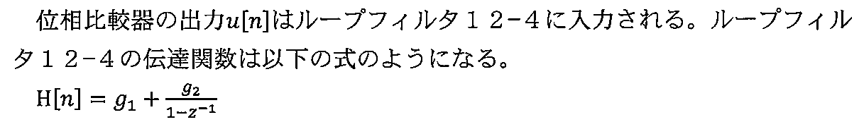

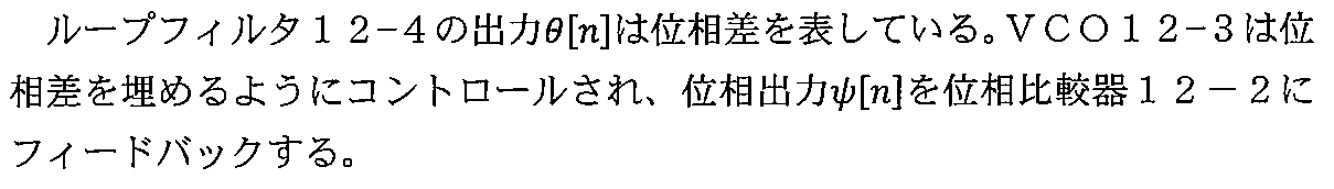


VCO12-3は、ディレイフリーループである。 VCO12-3 is a delay-free loop.
図10は、本実施の形態による制御アルゴリズムの一例を示す図である。 FIG. 10 is a diagram showing an example of a control algorithm according to the present embodiment.
この方法は、FFT解析した信号の中で、最大値を見つけ出し、目的の周波数に導くように周波数をコントロールする方法である。 This method is a method of finding the maximum value in the signal analyzed by FFT and controlling the frequency so as to lead to a target frequency.
脳波から測定したスペクトルの中で、α波近傍の極大値を検索し、初期はその極大値にPLLの周波数をLEDにフィードバックする。 In the spectrum measured from the brain wave, the maximum value near the α wave is searched, and the frequency of the PLL is initially fed back to the LED to the maximum value.
目的の周波数が極大値の周波数より大きいと仮定し、コントロールの次の手順として極大値より例えば1Hz大きい周波数にセットする。すると1Hz周波数が高いので1秒間に1波長分早く位相が回る。 Assuming that the target frequency is larger than the maximum frequency, the next step of control is to set the frequency to be, for example, 1 Hz higher than the maximum. Then, since the 1 Hz frequency is high, the phase turns one wavelength earlier per second.
そうすると、フィードバックによって目標の周波数に近づく。極大値+1Hzのレベルが上がると、再び、目標の周波数に向かって1Hzずつ近づける。目標の周波数に到達すると、そのまま周波数を維持する。 Then, the feedback approaches the target frequency. When the level of the maximum value + 1Hz rises, it approaches the target frequency by 1Hz again. When the target frequency is reached, the frequency is maintained as it is.
尚、計算の条件は以下の通りである。
BPF1: サンプリング周波数258Hz、 中心周波数fc: 10Hz、通過帯域幅: 5~15Hz
FFT: サンプリング周波数128Hz、解析レート 毎秒2回、解析分解能0.5HzThe calculation conditions are as follows.
BPF1: Sampling frequency 258Hz, center frequency fc: 10Hz, passband width: 5 to 15Hz
FFT: Sampling frequency 128Hz, analysis rate twice per second, analysis resolution 0.5Hz
周波数の切り替えは、例えば10秒間隔でFFTの結果を平均したものを使用する。 For frequency switching, for example, the average of the FFT results is used at 10-second intervals.
PLL: 出力レベルはVCOの設定で決定される。 PLL: The output level is determined by the VCO setting.
DELAYは、0~0.2s~ (5Hzの場合)α波周波数によって調整する。 DELAY is adjusted by the α wave frequency from 0 to 0.2 s (in the case of 5 Hz).
次に、サンプリングの方法とFFTの移動平均(加算平均)処理について説明する。 Next, the sampling method and the moving average (additional average) processing of the FFT will be described.
ここで、以下の条件のもとで処理を行う。
脳波の周波数帯域: 0.13~128Hz
α波の周波数帯域: 7~14Hz
サンプリング周波数: 128Hz×2=256Hz
必要サンプリング時間: 1/7Hz=0.143s
加算平均の時間: 10s
加算平均の回数: 10×2/0.143≒140回Here, the processing is performed under the following conditions.
EEG frequency band: 0.13 to 128Hz
Alpha wave frequency band: 7-14Hz
Sampling frequency: 128Hz x 2 = 256Hz
Required sampling time: 1 / 7Hz = 0.143s
Addition average time: 10s
Number of averaging: 10 x 2 / 0.143 ≒ 140 times
サンプリング方法は以下の通りである。 The sampling method is as follows.
サンプリング周波数はナイキスト周波数の定理より2倍とする。α波の最低周波数は7Hzであるので、必要サンプリング時間は0.143sである。サンプリング時間を長くすると、δ波まで周波数帯域を拡張できるが、加算平均の回数が減るので、フィードバックに使用するFFTと解析用のFFTを分けると良い。 The sampling frequency is twice the Nyquist frequency theorem. Since the lowest frequency of the α wave is 7 Hz, the required sampling time is 0.143 s. If the sampling time is lengthened, the frequency band can be extended to the delta wave, but the number of averaging is reduced, so it is better to separate the FFT used for feedback and the FFT for analysis.
FFTの加算平均
次にFFTの加算平均について説明する。Addition average of FFT Next, the addition average of FFT will be described.
図11は、加算平均の求め方の一例を示す図である。縦軸は振幅、横軸は時間であり、単位は任意である。実際には、msecオーダである。 FIG. 11 is a diagram showing an example of how to obtain the added average. The vertical axis is amplitude, the horizontal axis is time, and the unit is arbitrary. In reality, it is on the order of msec.
脳波をA/D変換によりサンプリングし、FFT解析を行う。例えば、10秒(図の0.1)の間、FFTのデータを加算平均して、α波周波数帯域内の最大周波数を検出する。その周波数を次の10秒間のVCOの周波数に反映させる。 Brain waves are sampled by A / D conversion and FFT analysis is performed. For example, for 10 seconds (0.1 in the figure), the FFT data are added and averaged to detect the maximum frequency in the α wave frequency band. The frequency is reflected in the VCO frequency for the next 10 seconds.
加算平均の方法は図11のようにフーリエ変換を複数回行う。 In the method of averaging, the Fourier transform is performed a plurality of times as shown in FIG.
サンプリング時間は、0.143sであるため、70回分のFFTデータを取得することができる。しかしながら、FFTは窓関数で処理するため、サンプリング時間を半分重ねて加算平均を取ったほうが良い。 Since the sampling time is 0.143 s, it is possible to acquire FFT data for 70 times. However, since the FFT is processed by the window function, it is better to overlap the sampling time by half and take the averaging.
そこで、例えば、FFT140回分のデータを加算平均する。加算平均をすることで、ホワイトノイズは1/√Nで減少する。ここで、Nは加算平均の回数である。 Therefore, for example, the data for 140 times of FFT are added and averaged. White noise is reduced by 1 / √N by averaging. Here, N is the number of addition averages.
次に、α波の最大周波数の変位とVCOの振る舞いについて図12を参照しながら説明する。 Next, the displacement of the maximum frequency of the α wave and the behavior of the VCO will be described with reference to FIG.
脳波から取り出したFFTデータを加算平均することによって、α波の最大周波数を検出する。α波の最大周波数が変動した場合、次の10秒間にVCO周波数を変更する。しかし、VCOの周波数は急に変更(図12(図12上図)するのではなく、ループフィルタ(図12中図)によって安定的に目的の周波数に変動させる(図12下図)。位相は緩やかに変位して目的の周波数に接続される。 The maximum frequency of the α wave is detected by adding and averaging the FFT data extracted from the brain wave. If the maximum frequency of the alpha wave fluctuates, the VCO frequency is changed in the next 10 seconds. However, the frequency of the VCO is not suddenly changed (in the upper figure of FIG. 12), but is stably changed to the target frequency by the loop filter (middle figure of FIG. 12) (the lower figure of FIG. 12). It is displaced to and connected to the desired frequency.
尚、図12では、アナログICのPLL処理を図示したものであるが、デジタル信号処理では位相差を数値で表現する。 Although FIG. 12 shows the PLL processing of the analog IC, the phase difference is expressed numerically in the digital signal processing.
尚、振幅はVCOで決定される。この振幅の値はプログラムによって設定できる。よって、初動のときに信号レベルを小さくしたり、FFTの最大周波数のレベルに比例させて信号レベルを変化させたりすることができる。 The amplitude is determined by the VCO. The value of this amplitude can be set programmatically. Therefore, the signal level can be reduced at the time of initial motion, or the signal level can be changed in proportion to the level of the maximum frequency of the FFT.
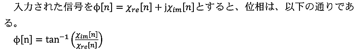
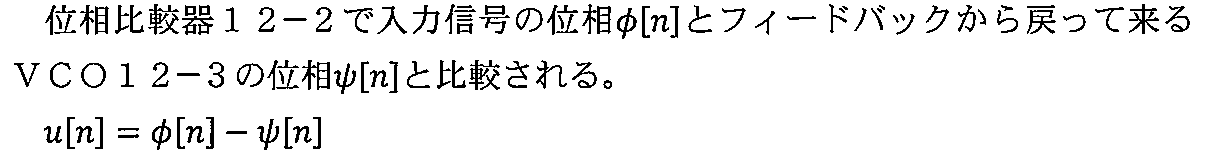
図13は、位相の同期方法を示す図である。横軸は時間、縦軸は振幅である。図13の上の波形は、α波のサンプリングデータであり、下の波形は、位相情報のみを取り出したデータである。 FIG. 13 is a diagram showing a phase synchronization method. The horizontal axis is time and the vertical axis is amplitude. The upper waveform in FIG. 13 is the sampling data of the α wave, and the lower waveform is the data obtained by extracting only the phase information.
BPFは10秒間隔ごとに周波数を切り替える。その切り替え時に入力の脳波と位相を合わせる。すなわち、α波のサンプリングデータから、位相のデータのみ取り出し振幅は一定とする。10秒間ごとの周波数切り替え時に、位相のみ取り出したサンプリングデータから、
θ=tan-1(A/B)により位相を計算する。その位相をVCOの位相と一致させる。BPF switches the frequency every 10 seconds. At the time of switching, the phase is matched with the input brain wave. That is, only the phase data is extracted from the α wave sampling data, and the amplitude is constant. From the sampling data obtained by extracting only the phase when switching the frequency every 10 seconds
The phase is calculated by θ = tan -1 (A / B). Match that phase with the phase of the VCO.
次に、周波数切換え時に位相を同期する方法について説明する。テスト結果で最良なものを選択することができる。 Next, a method of synchronizing the phases at the time of frequency switching will be described. You can choose the best test result.
1)同期方法1
図14は、第1の同期方法を示す図であり、横軸は時間、縦軸は振幅である。第1の同期方法は、周波数切り替え時に位相を同期する方法である。例えば、10秒間のFFT処理の加算平均のデータを使用して、次の10秒間のVCOの周波数を決定する。この方法で計算した位相でVCOの動作を開始する。1)
FIG. 14 is a diagram showing a first synchronization method, in which the horizontal axis is time and the vertical axis is amplitude. The first synchronization method is a method of synchronizing the phases at the time of frequency switching. For example, the data of the averaging of the FFT process for 10 seconds is used to determine the frequency of the VCO for the next 10 seconds. The operation of the VCO is started at the phase calculated by this method.
図14のグラフはVCOの周波数が低い周波数から高い周波数に切り替わったときのグラフを示している。切り替え時にサンプリングデータ(脳波の位相)とVCOの開始の位相を一致させることができる。 The graph of FIG. 14 shows a graph when the frequency of the VCO is switched from a low frequency to a high frequency. At the time of switching, the sampling data (phase of the brain wave) and the phase of the start of the VCO can be matched.
但し、切り替え前のVCOの位相と切換え後のVCOの位相は合わない。そのため、DCの変動が起きる可能性は残る。 However, the phase of the VCO before switching and the phase of the VCO after switching do not match. Therefore, there is a possibility that DC fluctuation will occur.
2)同期方法2
図15から図18までは、第2の同期方法を示す図であり、横軸は時間、縦軸は振幅である。第2の同期方法は、周波数切り替え後、ゼロクロス点で位相を同期する方法であり、例えば、10秒間の周波数切り替えポイントのあと、脳波のゼロクロスポイントまで遅延させ、同期をとるものである。2)
15 to 18 are diagrams showing the second synchronization method, in which the horizontal axis is time and the vertical axis is amplitude. The second synchronization method is a method of synchronizing the phase at the zero crossing point after frequency switching. For example, after the frequency switching point for 10 seconds, the phase is delayed to the zero crossing point of the brain wave to synchronize.
脳波の位相とVCOの位相の同期を取るため、ゼロクロスポイントまで空白の時間が出る。余計な高調波は発生しないが、脳波の位相が0になかなか戻ってこない場合、空白期間が長くなる可能性がある。 Since the phase of the brain wave and the phase of the VCO are synchronized, there is a blank time until the zero cross point. No extra harmonics are generated, but if the phase of the brain wave does not return to 0 easily, the blank period may become long.
図15、図16は、上図が脳波の波形、下図がVCOの波形である。10秒の周波数切換えポイントt2と、VCOの位相を脳波の位相と合わせるポイントt3との間ので、VCOの波形をゼロに維持する。図15は、t1からt2(t1<t2)へVCOの波形における振幅が減少する期間で0にクロスする例であり、図16は、t1からt2(t1<t2)へVCOの波形における振幅が増加する期間で0にクロスする例である。10秒間の周波数切り替えポイントのあと、脳波のゼロクロスポイントまで遅延させ、同期をとる。In FIGS. 15 and 16, the upper figure is the waveform of the brain wave, and the lower figure is the waveform of the VCO. The waveform of the VCO is maintained at zero because it is between the frequency switching point t2 for 10 seconds and the point t3 that matches the phase of the VCO with the phase of the brain wave. FIG. 15 shows an example of crossing to 0 from t 1 to t 2 (t 1 <t 2 ) during the period when the amplitude in the VCO waveform decreases, and FIG. 16 shows an example of crossing from t 1 to t 2 (t 1 <t 2 ). This is an example of crossing to 0 during the period when the amplitude in the waveform of VCO increases. After the frequency switching point for 10 seconds, it is delayed to the zero cross point of the brain wave and synchronized.
図17は、VCOの波形における極大値を取るタイミングを10秒の周波数切換えポイントとする例であり、図18は、VCOの波形における極小値を取るタイミングを10秒の周波数切換えポイントとする例である。 FIG. 17 is an example in which the timing of taking the maximum value in the VCO waveform is set as the frequency switching point of 10 seconds, and FIG. 18 is an example in which the timing of taking the minimum value in the VCO waveform is set as the frequency switching point of 10 seconds. be.
以上のいずれかの同期方法により、脳波の位相とVCOの位相の同期を取るため、ゼロクロスポイントまで空白の時間が出る。余計な高調波は発生しないが、脳波の位相が0になかなか戻ってこない場合、空白期間が長くなる可能性がある。 By any of the above synchronization methods, the phase of the brain wave and the phase of the VCO are synchronized, so that a blank time appears until the zero cross point. No extra harmonics are generated, but if the phase of the brain wave does not return to 0 easily, the blank period may become long.
図19は、上記の同期処理の流れの一例を示すフローチャート図である。図19に示すように、処理が開始され(Start)、切換えのインターラプト(中断)をタイミングt1で行う(ステップS31)。 FIG. 19 is a flowchart showing an example of the flow of the above synchronization processing. As shown in FIG. 19, the process is started (Start), and the switching interrupt (interruption) is performed at the timing t1 (step S31).
次いで、ステップS32において、VCOの位相がゼロクロスポイントに来るまで発振を継続する。 Then, in step S32, oscillation is continued until the phase of the VCO reaches the zero cross point.
ステップS33において、PLLの位相がゼロであるか否かを判定する。ゼロであれば(Yes)、ステップS34に進む。Noであれば、PLLの位相がゼロになるまで待つ。 In step S33, it is determined whether or not the phase of the PLL is zero. If it is zero (Yes), the process proceeds to step S34. If No, wait until the phase of the PLL becomes zero.
ステップS34において、前回の10秒の平均の周波数でPLLの信号出力を開始し、処理を終了する。 In step S34, the signal output of the PLL is started at the average frequency of the previous 10 seconds, and the process is finished.
以上のようにして、近赤外LEDへの制御信号の位相の自己脳波の位相への同期を速やかに行うことができる。 As described above, the phase of the control signal to the near-infrared LED can be quickly synchronized with the phase of the self-electroencephalogram.
本実施の形態によれば、上記の第1から第4の実施の形態で説明した技術において、被験者に処方を施す時に、被験者の脳波と装置のフィードバック光の位相とが一致させることで被験者が装置に慣れるまで初動段階(初期段階)においても、その効果が得られるという利点がある。 According to the present embodiment, in the technique described in the first to fourth embodiments described above, when prescribing to the subject, the subject causes the subject to match the phase of the subject's brain wave with the phase of the feedback light of the device. There is an advantage that the effect can be obtained even in the initial stage (initial stage) until the device gets used to it.
(第6の実施の形態)
図20は、本発明の第6の実施の形態による光刺激装置の構成例を示す図であり、第1~第6までの各実施の形態による処理を行って得た赤色パルス光を、被験者の頭部に照射するための器具の一例を示す図である。図20(c)に示すように、出射穴57aの位置に図示しないLED4が多数配置された支持板57が裏面(頭部側の被照射領域)に設けられた帽子状の部材51を被る。(Sixth Embodiment)
FIG. 20 is a diagram showing a configuration example of the light stimulator according to the sixth embodiment of the present invention, and the subject receives red pulse light obtained by performing the treatment according to each of the first to sixth embodiments. It is a figure which shows an example of the instrument for irradiating the head of a person. As shown in FIG. 20 (c), a support plate 57 in which a large number of LEDs 4 (not shown) are arranged at the position of the emission hole 57a covers a hat-shaped
波形生成部1aとパルス変調部3(図1A)等により生成したパルス駆動電圧に基づいて、頭部に赤色光が照射される。ここで、帽子状の部材51の照射部51aを被照射領域と合わせておく。そして、実際に光を照射する際には、帽子状の部材51に摺動可能に設けられた目保護部53を眼の位置までスライドさせて目を保護する(図20(a))。
The head is irradiated with red light based on the pulse drive voltage generated by the
図20(b)に示すように、目保護部53を眼の位置からスライドさせると、照射部51aと被照射領域との間に位置するように構成されており、照射部51aからの光を遮蔽することで目を保護することができる。
As shown in FIG. 20B, when the eye protection unit 53 is slid from the position of the eye, it is configured to be located between the
以上のように、本実施の形態では、光照射と目の保護とを有効に行うことができる。 As described above, in the present embodiment, light irradiation and eye protection can be effectively performed.
(第7の実施の形態)
図21は、本発明の第7の実施の形態による光刺激装置の構成例を示す図であり、第1~第6までの各実施の形態による処理を行って得た赤色線パルス光を、被験者の頭部に照射するための器具の他の例を示す図である。(7th embodiment)
FIG. 21 is a diagram showing a configuration example of the light stimulator according to the seventh embodiment of the present invention, and the red ray pulsed light obtained by performing the processing according to each of the first to sixth embodiments is shown. It is a figure which shows the other example of the instrument for irradiating the head of a subject.
図21(a)、(b)に示す頭部の装着する光パルス装置151において、装置のハウジング153の内部には、発光部155の他に、例えば信号処理部157、電源(電池等)161が配置されている。信号処理部157、電源(電池等)161は、ハウジング153の外側に配置されていても良い。
In the
この構成において、脳を刺激する光の動作(起動、停止)を容易にモニタするために、図21(b)、(c)に示すように、ハウジング153の内部の光の一部を使用者の目に入る場所に導き、使用者に動作モニタ光を投射する機能を配置している。 In this configuration, in order to easily monitor the movement (start, stop) of the light that stimulates the brain, as shown in FIGS. 21 (b) and 21 (c), a part of the light inside the housing 153 is used by the user. It has a function to guide the user to a place where he / she can see it and to project the operation monitor light to the user.
このように、頭部に装着する光パルス装置151において、目で見える位置に、機器の動作確認のための、内部の光刺激信号の一部を確認できる窓163が設けられている。そして、その光の眼の方向への導光路上に、減光するための調整窓があり、明るさを変えたい場合に調整窓を操作して明るさを調整することができる。
As described above, in the
この調整窓163による光の調整性は、透過率の異なる色素により行っても良いし、導光路上の遮蔽物でもよく、動作確認窓で確認灯の明るさを調整する装置であれば良い。 The light adjustment by the adjustment window 163 may be performed by dyes having different transmittances, may be a shield on the light guide path, or may be a device that adjusts the brightness of the confirmation lamp through the operation confirmation window.
例えば、図21(c)、(d)に示すように、この機能は、例えば、動作確認窓163を含み、動作モニタ光を、調光、または遮蔽できるように調整スイッチ機能を設ける。 For example, as shown in FIGS. 21 (c) and 21 (d), this function includes, for example, an operation confirmation window 163, and is provided with an adjustment switch function so that the operation monitor light can be dimmed or shielded.
調整スイッチ機能は、例えば、図21(c)、(d)に示すように、動作確認窓163を望む位置にスリット165とスリット165の開口範囲を調整可能に配置された遮光板164とを設けている。遮光板164をスライドさせることによりスリット165の開口範囲を調整することで、屋外、室内等で外部環境の明るさが変化した場合に、眩しすぎたり暗すぎたりしないように調整または遮光可能となっている。
For the adjustment switch function, for example, as shown in FIGS. 21 (c) and 21 (d), a
以上のように、本実施の形態によれば、内部の光学的な状態を検知する検出窓(孔)であり、明るさ、動作を確認する表示を行い、システム側の起動および停止を容易にするためのモニタが可能である。 As described above, according to the present embodiment, it is a detection window (hole) for detecting the optical state inside, and a display for confirming the brightness and operation is displayed, and the system side can be easily started and stopped. It is possible to monitor for this.
処理および制御は、CPU(Central Processing Unit)やGPU(Graphics Processing Unit)によるソフトウェア処理、ASIC(Application Specific Integrated Circuit)やFPGA(Field Programmable Gate Array)によるハードウェア処理によって実現することができる。 Processing and control can be performed by software processing by CPU (Central Processing Unit) or GPU (Graphics Processing Unit), by ASIC (Application Specific Integrated Circuit) or FPGA (Field Programmable Hardware).
本発明の装置を使用することによりヒト脳における退化した機能の蘇生が可能になる。具体的には、本発明によれば前頭前野(前頭連合野)を中心に、各人固有の脳波のリズムに基づいて、自動的に調整された頭部へのパルス光照射により、自然発生中のα波とθ波の振幅を増強させ、これにより、無侵襲に大脳皮質の神経インパルスの増強、内分泌系の変化によるリラクゼーション及び細胞性免疫の活性化を図ることができる。 The use of the apparatus of the present invention enables resuscitation of degenerated functions in the human brain. Specifically, according to the present invention, the prefrontal cortex (frontal cortex) is naturally generated by pulsed light irradiation to the head automatically adjusted based on the rhythm of the brain wave peculiar to each person. By enhancing the amplitudes of the alpha and theta waves, it is possible to non-invasively enhance the nerve impulses of the cerebral cortex, relax by changing the endocrine system, and activate cellular immunity.
ヒトの進化の過程においては、非常に重要なパーツを(特に生活に関係する物理的要因から)守るために(骨格を含む)器官の変化(進化)が起きる。(このように、環境に応じて進化した種や亜種が自然選択され今日存在していると考えられている。)その進化のために(進化と引き換えに)、本来もちあわせていた生理学的な賦活化や調節に関する機能が徐々に退化することが少なからずある。本発明は、このようにして退化せざるをえなくなった生理学的及び免疫学的機能を蘇らせる技術の典型例と言える。 In the process of human evolution, changes (evolution) of organs (including the skeleton) occur in order to protect very important parts (especially from physical factors related to life). (Thus, it is believed that species and subspecies that have evolved according to the environment are naturally selected and exist today.) Physiologically originally possessed for that evolution (in exchange for evolution). It is not uncommon for the functions related to activation and regulation to gradually decline. The present invention can be said to be a typical example of a technique for reviving the physiological and immunological functions that have been forced to degenerate in this way.
本発明の装置は、ヒト頭部、とりわけ前頭前野(前頭連合野)を中心に特定波長域の赤色パルス光で刺激することによって、生理現象のリズム(ゆらぎ)の範囲を超えた生体内の歪みから生じるα波の周波数や振幅の乱れを、各人固有のθ波の一部帯域~α波一部帯域の間の周波数及び振幅に同調及び増幅させることにより改善しさらに予防することを可能にする。この頭部の光刺激は、脳表面(主として大脳皮質)の退化した光感受性機能の蘇生を起こし、大脳皮質での神経細胞の興奮促進をもたらして神経インパルスの増強が起こり(内分泌系の変化による精神的ストレスの改善などをもたらすとともに)自然免疫系(細胞性免疫)の活性化を起こす。これが免疫監視能の増強となり、ウイルス感染細胞や(健常者でも1日に3千~5千個も発生していると言われる)ガン細胞に対する攻撃・防御をもたらすものと推定されている。 The device of the present invention is distorted in the living body beyond the range of the rhythm (fluctuation) of physiological phenomena by stimulating the human head, especially the frontal frontal area (frontal association area) with red pulsed light in a specific frequency range. It is possible to improve and further prevent the disturbance of the frequency and amplitude of the α wave generated from the above by tuning and amplifying the frequency and amplitude between the partial band of the θ wave and the partial band of the α wave peculiar to each person. do. This light stimulation of the head causes the revival of the degenerated photosensitive function of the brain surface (mainly the cerebral cortex), promotes the excitement of nerve cells in the cerebral cortex, and enhances the nerve impulse (due to changes in the endocrine system). It brings about improvement of mental stress and activates the natural nervous system (cell-mediated immunity). It is presumed that this enhances the immune monitoring ability and brings about attack and defense against virus-infected cells and cancer cells (which are said to occur in 3,000 to 5,000 cells a day even in healthy people).
免疫系には、獲得免疫系と自然免疫系(細胞性免疫)がある。獲得免疫系では、体内に細菌やウイルスなどの異物が侵入したとき樹状細胞などの抗原提示細胞がヘルパーT細胞に抗原を提示し異物の情報を伝えることによってヘルパーT細胞はB細胞に指令して抗原に対する抗体を作らせ、この抗体が異物を攻撃し破壊する。一方、自然免疫系(細胞性免疫)は、獲得免疫系が作用する前に上記の異物に対し即効的に攻撃できるようにパトロールしているNK細胞、マクロファージ(貪食細胞)及び顆粒球(好中球)による初期防御のための免疫系である。本発明の装置による頭部の光刺激ではNK細胞の活性化が生じるという特徴がある。尚、NK細胞数の増加は、末梢血中のNK細胞の細胞表面抗原であるCD57及びCD16(ここでCDは「Cluster of Differentiation」の略である。)についてCD57-CD16+及びCD57+CD16+の細胞の存在量をフローサイトメトリー法などにより測定して確認することができる。The immune system includes the adaptive immune system and the innate immune system (cell-mediated immunity). In the adaptive immune system, when a foreign substance such as a bacterium or a virus invades the body, an antigen-presenting cell such as a dendritic cell presents an antigen to the helper T cell and conveys information on the foreign substance, so that the helper T cell commands the B cell. To make an antibody against the antigen, and this antibody attacks and destroys foreign substances. On the other hand, the innate immune system (cell-mediated immunity) is patroling NK cells, macrophages (phagocytic cells) and granulocytes (neutrophils) so that they can immediately attack the above-mentioned foreign substances before the acquired immune system acts. It is an immune system for initial defense by spheres). Light stimulation of the head by the apparatus of the present invention is characterized by activation of NK cells. The increase in the number of NK cells is due to CD57 - CD16 + and CD57 + CD16 + for CD57 and CD16 (here, CD is an abbreviation for "Cruster of Differentiation"), which are cell surface antigens of NK cells in peripheral blood. The abundance of cells can be measured and confirmed by a flow cytometry method or the like.
ヒト脳のα波を制御することによって免疫力を高めることは知られていたが、特に0.5~13Hzの周波数のパルス光の光刺激によるNK細胞の活性化やリラクセーション効果は本発明者らにより特開平9-84888号公報や特開2001-231871号などにも記載されている。しかしこの技術は、前述のとおり、個人差(もしくは個体差)及び体質を考慮したものでなく頭部に画一的な光を照射するものであり、その効果に個人差が大きいという問題があった。ヒト脳波のうち安静閉眼時にα波(周波数13~8Hz)、浅い睡眠時にθ波(周波数7~4Hz)が出現する。覚醒時にはβ波(周波数30~14Hz)が主になり緊張やストレスの影響を受ける。本発明の装置は、各人の脳波を測定し各人固有のα波のリズムの周波数及び振幅に自動的に合わせた赤色パルス光(610~750nmの任意の波長域使用)を、頭部、例えば前頭前野(前頭連合野)を中心に照射することにより自然発生中のθ波の一部帯域~α波の一部帯域(通常7~13Hz、好ましくは7~12Hz、より好ましくは7~10Hz)の脳波の振幅を増強することを可能にする。実際、健常者、ガン患者、高齢者などに対する本発明における赤色パルス光照射の実施により、例えば1日1~6回(1日4~6回の場合は、例えば午前中1・2回目を15分間以上の“休憩時間(interval)をおいて実施、午後にもこの2回分のセットを1~2回行うという方法をとる。)、各回約15分間、約2~3週間もしくはそれ以上の期間実施することにより、大脳皮質の神経インパルスの増強(大脳皮質機能の賦活化)、内分泌系の変化による生体としての活性化(例えば血中ノルエピネフリン [ノルアドレナリン]レベルの低下によるイライラ感の低下や精神的ストレスの軽減など)、自然免疫系(細胞性免疫)の活性化(例えばNK細胞活性の上昇)がもたらされることを確認した。
It has been known that the immune power is enhanced by controlling the α wave of the human brain, but in particular, the activation and relaxation effect of NK cells by the light stimulation of pulsed light having a frequency of 0.5 to 13 Hz are exhibited by the present inventors. It is also described in JP-A-9-84888 and JP-A-2001-231871. However, as mentioned above, this technique does not consider individual differences (or individual differences) and constitution, but irradiates the head with uniform light, and there is a problem that the effect is large among individuals. rice field. Of the human brain waves, α waves (
本発明のような技術を用いることによって、脳表面(発生学的に終脳と呼ばれる部位)に元来存在していた光感受性をよみがえらせることにより、現代人の脳においては退化しつつある上記生理学的機能の一部(例えば、大脳皮質の神経インパルスの増強、内分泌系の変化による生体としての活性化、及び細胞性免疫の活性化など)を蘇生させることが可能になる。本発明者らの一連の医工連携による研究を通して、この大脳皮質の光感受性を蘇生させ自然治癒力を蘇らせることが可能になった。 By using a technique like the present invention, the photosensitivity that originally existed on the surface of the brain (a site that is developmentally called the endocrine) is revived, and the above is deteriorating in the modern human brain. It is possible to resuscitate some of the physiological functions (eg, enhancement of neural impulses in the cerebral cortex, activation as a living body by changes in the endocrine system, activation of cell-mediated immunity, etc.). Through a series of researches by the present inventors through a series of medical-engineering collaborations, it has become possible to revive the photosensitivity of this cerebral cortex and restore the natural healing power.
上記の実施の形態において、添付図面に図示されている構成等については、これらに限定されるものではなく、本発明の効果を発揮する範囲内で適宜変更することが可能である。その他、本発明の目的の範囲を逸脱しない限りにおいて適宜変更して実施することが可能である。 In the above embodiment, the configuration and the like shown in the accompanying drawings are not limited to these, and can be appropriately changed within the range in which the effects of the present invention are exhibited. In addition, it can be appropriately modified and implemented as long as it does not deviate from the scope of the object of the present invention.
また、本発明の各構成要素は、任意に取捨選択することができ、取捨選択した構成を具備する発明も本発明に含まれるものである。 In addition, each component of the present invention can be arbitrarily selected, and an invention having the selected configuration is also included in the present invention.
本発明は、頭部への光パルス照射装置に利用可能である。 The present invention can be used for an optical pulse irradiation device for the head.
本発明は、光刺激装置に利用可能である。 The present invention can be used for a light stimulator.
1a…波形生成部、1-1…BPF部、3…(PWM)パルス変調部、4…光照射部(LED)、11…脳波センサ、12…PLL(フェーズドロックループ)部、13…脳波アンプ、15…FFT(フーリエ変換)部、17…周波数及び位相の制御部、51…帽子状の部材、51a…照射部、51b…遮断部、53…目保護部、57…支持板、57a…出射穴。 1a ... waveform generation unit, 1-1 ... BPF unit, 3 ... (PWM) pulse modulation unit, 4 ... light irradiation unit (LED), 11 ... brain wave sensor, 12 ... PLL (phased lock loop) unit, 13 ... brain wave amplifier , 15 ... FFT (Fourier transform) unit, 17 ... Frequency and phase control unit, 51 ... Hat-shaped member, 51a ... Irradiation unit, 51b ... Blocking unit, 53 ... Eye protection unit, 57 ... Support plate, 57a ... Emission hole.
本明細書で引用した全ての刊行物、特許および特許出願をそのまま参考として本明細書にとり入れるものとする。 All publications, patents and patent applications cited herein are incorporated herein by reference in their entirety.
Claims (5)
前記制御信号生成回路は、
前記脳波アンプからの出力信号をフィルタ処理するフィルタであって、θ波の一部帯域とα波の一部帯域を含む周波数帯域を通過させるバンドパスフィルタと、
前記自己脳波の位相と、前記光照射部のLEDを駆動するための前記駆動信号の位相とを一致させるために、前記バンドパスフィルタからの出力信号の位相に一致させた位相の前記制御信号を出力するフェーズドロックループと、を有し、
前記フェーズドロックループは、
入力信号の位相を比較する位相比較器と、
ループフィルタと、
前記ループフィルタの出力を入力として前記位相比較器にその出力をフィードバックするVCOと、
を有する頭部光刺激装置。 A brain wave amplifier that A / D-converts the self-brain wave acquired by the brain wave sensor and amplifies it, a control signal generation circuit that generates a control signal based on an output signal from the brain wave amplifier, and a control signal generation circuit are generated. It is provided with a pulse modulation unit that pulse-modulates the control signal and outputs a drive signal, and a light irradiation unit equipped with an LED that is driven based on the drive signal and irradiates the head with LED light.
The control signal generation circuit is
A filter that filters the output signal from the electroencephalogram amplifier, and is a bandpass filter that passes through a frequency band including a part of theta wave and a part of the α wave.
In order to match the phase of the self-brain wave with the phase of the drive signal for driving the LED of the light irradiation unit, the control signal having a phase matched with the phase of the output signal from the bandpass filter is used. Has a phased lock loop and outputs
The phased lock loop is
A phase comparator that compares the phase of the input signal and
With a loop filter,
A VCO that takes the output of the loop filter as an input and feeds back the output to the phase comparator,
Head light stimulator with.
前記フェーズドロックループは、その周波数の切り替え時に、前記バンドパスフィルタからの出力信号の位相に一致させた位相の前記制御信号を出力する、
請求項1に記載の頭部光刺激装置。 The frequency of the control signal output from the phased lock loop is switched at predetermined intervals .
The phased lock loop outputs the control signal having a phase matched to the phase of the output signal from the bandpass filter when the frequency is switched .
The head light stimulator according to claim 1.
前記フェーズドロックループは、前記バンドパスフィルタからの出力信号のゼロクロスポイントのタイミングで、前記バンドパスフィルタからの出力信号の位相に一致させた位相の前記制御信号を出力する、請求項1に記載の頭部光刺激装置。 The frequency of the control signal output from the phased lock loop is switched at predetermined intervals.
The phased lock loop according to claim 1 , wherein the phased lock loop outputs the control signal having a phase matched with the phase of the output signal from the bandpass filter at the timing of the zero crossing point of the output signal from the bandpass filter . Head light stimulator.
前記頭部光刺激装置に、
前記脳波アンプからの出力信号をフィルタするフィルタ処理であって、θ波の一部帯域とα波の一部帯域を含む周波数帯域を通過させるバンドパスフィルタ処理と、
前記自己脳波の位相と、前記光照射部のLEDを駆動するための前記駆動信号の位相とを一致させるために、前記バンドパスフィルタ処理された出力信号の位相に一致させた位相の前記制御信号を出力するフェーズドロックループ処理と、
を実行させるためのプログラム。 A brain wave amplifier that A / D-converts the self-brain wave acquired by the brain wave sensor and amplifies it, a control signal generation circuit that generates a control signal based on an output signal from the brain wave amplifier, and a control signal generation circuit are generated. Head light including a pulse modulation unit that pulse-modulates the control signal and outputs a drive signal, and a light irradiation unit having an LED that is driven based on the drive signal and irradiates the head with LED light. It is a program to operate the stimulator,
To the head light stimulator
A filter process for filtering the output signal from the electroencephalogram amplifier, which is a bandpass filter process for passing a frequency band including a part band of theta wave and a part band of the α wave.
In order to match the phase of the self-brain wave with the phase of the drive signal for driving the LED of the light irradiation unit, the control signal having a phase matched with the phase of the bandpass- filtered output signal. Phased lock loop processing to output
A program to execute.
Applications Claiming Priority (1)
| Application Number | Priority Date | Filing Date | Title |
|---|---|---|---|
| PCT/JP2016/073194 WO2018025419A1 (en) | 2016-08-05 | 2016-08-05 | Head part photic stimulation device, head part photic stimulation method, and program |
Publications (2)
| Publication Number | Publication Date |
|---|---|
| JPWO2018025419A1 JPWO2018025419A1 (en) | 2019-05-23 |
| JP7025734B2 true JP7025734B2 (en) | 2022-02-25 |
Family
ID=61072892
Family Applications (1)
| Application Number | Title | Priority Date | Filing Date |
|---|---|---|---|
| JP2018531726A Active JP7025734B2 (en) | 2016-08-05 | 2016-08-05 | Head light stimulator and program |
Country Status (5)
| Country | Link |
|---|---|
| US (1) | US11331511B2 (en) |
| EP (1) | EP3495021B1 (en) |
| JP (1) | JP7025734B2 (en) |
| CN (1) | CN109562273B (en) |
| WO (1) | WO2018025419A1 (en) |
Families Citing this family (10)
| Publication number | Priority date | Publication date | Assignee | Title |
|---|---|---|---|---|
| USD949355S1 (en) | 2019-10-15 | 2022-04-19 | JelikaLite, LLC | Head wearable light therapy device |
| JP7786659B2 (en) | 2019-10-15 | 2025-12-16 | ジェリカライト エルエルシー | Wearable head-mounted light therapy device |
| WO2021257548A1 (en) | 2020-06-18 | 2021-12-23 | Diagnostyx, Inc. | Treatment of neurological abnormalities using dynamic electroencephalography |
| CA3212308A1 (en) * | 2021-03-17 | 2022-09-22 | Jelikalite Llc | Methods and devices for photobiomodulation |
| US11944840B2 (en) | 2021-04-08 | 2024-04-02 | Niraxx Light Therapeutics, Inc. | Photobiomodulation therapy garment, methods and uses |
| JP2024514558A (en) | 2021-04-08 | 2024-04-02 | ニーラックス インコーポレイテッド | Photobiomodulation Therapy Garments, Methods, and Uses Thereof |
| CN115089197A (en) * | 2022-06-08 | 2022-09-23 | 上海暖禾脑科学技术有限公司 | A closed-loop feedback optical stimulation system based on gamma EEG signals |
| CN115886731A (en) * | 2022-11-22 | 2023-04-04 | 秦皇岛市惠斯安普医学系统股份有限公司 | Cognitive dysfunction governing system |
| CN116015296B (en) * | 2022-12-02 | 2023-09-29 | 北京津发科技股份有限公司 | A signal sampling system based on multimodal brain imaging |
| CN118698042B (en) * | 2024-05-31 | 2025-09-30 | 北京脑科学与类脑研究所 | Transcranial photostimulation devices and systems |
Citations (1)
| Publication number | Priority date | Publication date | Assignee | Title |
|---|---|---|---|---|
| JP2002035130A (en) | 2000-03-31 | 2002-02-05 | Tsutomu Kamei | Method and apparatus for activating brain |
Family Cites Families (22)
| Publication number | Priority date | Publication date | Assignee | Title |
|---|---|---|---|---|
| US5241967A (en) * | 1988-12-23 | 1993-09-07 | Pioneer Electronic Corporation | System for evoking electroencephalogram signals |
| DE68920418T2 (en) * | 1988-12-23 | 1995-08-17 | Pioneer Electronic Corp | System for evoking electroencephalographic signals. |
| JP2725039B2 (en) | 1988-12-23 | 1998-03-09 | パイオニア株式会社 | Brain wave guidance device |
| JPH0712378B2 (en) * | 1989-08-10 | 1995-02-15 | パイオニア株式会社 | EEG guiding goggles and EEG guiding device |
| GB2258149B (en) * | 1991-05-28 | 1995-06-07 | Matsushita Electric Works Ltd | Relaxation refreshment apparatus |
| JP3292735B2 (en) * | 1991-05-28 | 2002-06-17 | パイオニア株式会社 | Brain wave guidance device |
| US5769878A (en) | 1995-03-23 | 1998-06-23 | Kamei; Tsutomu | Method of noninvasively enhancing immunosurveillance capacity |
| US6129748A (en) | 1996-03-22 | 2000-10-10 | Kamei; Tsutomu | Apparatus for applying pulsed light to the forehead of a user |
| JPH0984888A (en) | 1995-03-23 | 1997-03-31 | Tsutomu Kamei | Method for noninvasively reinforcing immunity-inspecting ability and tool for irradiating forehead region with pulse light |
| US20030181961A1 (en) | 1995-03-23 | 2003-09-25 | Tsutomu Kamei | Method of noninvasively enhancing immunosurveillance capacity and apparatus for applying pulsed light to at least a portion of a user's temporal region |
| JP2918489B2 (en) * | 1996-02-21 | 1999-07-12 | パイオニア株式会社 | Brain wave guidance device |
| JP2001231871A (en) | 2000-02-22 | 2001-08-28 | Tsutomu Kamei | Method for activating brain and immune mechanism and irradiation tool used for the activation |
| JP2004089572A (en) * | 2002-09-03 | 2004-03-25 | Yaskawa Electric Corp | Relaxation device and control method thereof |
| JP4115413B2 (en) * | 2003-10-31 | 2008-07-09 | シーシーエス株式会社 | Phototherapy device |
| WO2007149553A2 (en) * | 2006-06-22 | 2007-12-27 | Us Government As Represented By The Secretary Of The Army | Alertness/drowsiness and cognitive capacity index |
| JP5967935B2 (en) * | 2008-04-04 | 2016-08-10 | イミュノライト・エルエルシー | Non-invasive system and method for photobiomodulation in situ |
| DE102009025407B4 (en) * | 2009-06-18 | 2020-07-09 | Forschungszentrum Jülich GmbH | Device for stimulating neuronal tissue using optical stimuli |
| US8771328B2 (en) * | 2011-09-08 | 2014-07-08 | La Lumiere Llc | Light therapy platform system |
| WO2014116939A1 (en) * | 2013-01-25 | 2014-07-31 | Hardt James V | Isochronic tone augmented biofeedback system |
| CN203154622U (en) * | 2013-03-28 | 2013-08-28 | 牛学霞 | Infantile autism treatment instrument |
| WO2016028635A1 (en) * | 2014-08-18 | 2016-02-25 | Northwestern University | Phase-locked loop to enhance slow wave sleep |
| CN105126256B (en) * | 2015-09-24 | 2017-06-23 | 黄勇 | A kind of near-infrared light therapy device for treating alzheimer disease |
-
2016
- 2016-08-05 JP JP2018531726A patent/JP7025734B2/en active Active
- 2016-08-05 US US16/316,898 patent/US11331511B2/en active Active
- 2016-08-05 CN CN201680087848.XA patent/CN109562273B/en not_active Expired - Fee Related
- 2016-08-05 EP EP16911678.7A patent/EP3495021B1/en not_active Not-in-force
- 2016-08-05 WO PCT/JP2016/073194 patent/WO2018025419A1/en not_active Ceased
Patent Citations (1)
| Publication number | Priority date | Publication date | Assignee | Title |
|---|---|---|---|---|
| JP2002035130A (en) | 2000-03-31 | 2002-02-05 | Tsutomu Kamei | Method and apparatus for activating brain |
Non-Patent Citations (1)
| Title |
|---|
| 亀井勉,医工連携による血中ノルアドレナリン低下を安全にもたらす新しい技術,Journal of International Society of life Information Science,2014年,Vol. 32, No. 2,pp.193-198 |
Also Published As
| Publication number | Publication date |
|---|---|
| JPWO2018025419A1 (en) | 2019-05-23 |
| US20190299021A1 (en) | 2019-10-03 |
| WO2018025419A1 (en) | 2018-02-08 |
| CN109562273A (en) | 2019-04-02 |
| US11331511B2 (en) | 2022-05-17 |
| EP3495021A1 (en) | 2019-06-12 |
| EP3495021A4 (en) | 2019-12-18 |
| CN109562273B (en) | 2021-11-30 |
| EP3495021B1 (en) | 2021-09-29 |
Similar Documents
| Publication | Publication Date | Title |
|---|---|---|
| JP7025734B2 (en) | Head light stimulator and program | |
| JP7719465B2 (en) | Devices that improve, prevent, or enhance brain function | |
| KR20230017838A (en) | Ultrasound systems and related devices and methods for regulating brain activity | |
| JP6037082B1 (en) | Photostimulator, photostimulation method and program | |
| US20170224949A1 (en) | Methods For Treating Brain Malfunctions | |
| US11730917B2 (en) | Gamma stimulation pulsing light source system with dosage adjustment for gaze angle | |
| WO2023069717A1 (en) | Modulation of the theta-gamma neural code with controlled light therapeutics | |
| US20180169435A1 (en) | Methods of Treating a Healthy Brain Using Light Therapy | |
| KR20230113165A (en) | Sleep inducing system using photobiomodulation by transcranial near-infrared Light irradiation | |
| JP6490649B2 (en) | Photostimulator, photostimulation method and program | |
| US20230256262A1 (en) | Phototherapeutic apparatus | |
| RU2780128C1 (en) | Device for audiovisual cortex stimulation | |
| Dorokhov et al. | Neurotechnologies for the Nonpharmacological Treatment of Sleep Disorders | |
| WO2025258699A1 (en) | Device and method for preventing, improving, or preventing worsening of depression, and method for operating the device | |
| Jafarzadehesfahani et al. | Closed-loop auditory stimulation of sleep slow oscillations: Basic principles and best practices | |
| Esfahani et al. | Royal Netherlands Academy of Arts and Sciences (KNAW) | |
| WO2024218088A1 (en) | Phototherapeutic apparatus |
Legal Events
| Date | Code | Title | Description |
|---|---|---|---|
| A621 | Written request for application examination |
Free format text: JAPANESE INTERMEDIATE CODE: A621 Effective date: 20190201 |
|
| A131 | Notification of reasons for refusal |
Free format text: JAPANESE INTERMEDIATE CODE: A131 Effective date: 20200212 |
|
| A521 | Request for written amendment filed |
Free format text: JAPANESE INTERMEDIATE CODE: A523 Effective date: 20200410 |
|
| A131 | Notification of reasons for refusal |
Free format text: JAPANESE INTERMEDIATE CODE: A131 Effective date: 20200526 |
|
| A521 | Request for written amendment filed |
Free format text: JAPANESE INTERMEDIATE CODE: A523 Effective date: 20200715 |
|
| A131 | Notification of reasons for refusal |
Free format text: JAPANESE INTERMEDIATE CODE: A131 Effective date: 20201216 |
|
| A521 | Request for written amendment filed |
Free format text: JAPANESE INTERMEDIATE CODE: A523 Effective date: 20210126 |
|
| A131 | Notification of reasons for refusal |
Free format text: JAPANESE INTERMEDIATE CODE: A131 Effective date: 20210629 |
|
| A521 | Request for written amendment filed |
Free format text: JAPANESE INTERMEDIATE CODE: A523 Effective date: 20210803 |
|
| TRDD | Decision of grant or rejection written | ||
| A01 | Written decision to grant a patent or to grant a registration (utility model) |
Free format text: JAPANESE INTERMEDIATE CODE: A01 Effective date: 20220104 |
|
| A61 | First payment of annual fees (during grant procedure) |
Free format text: JAPANESE INTERMEDIATE CODE: A61 Effective date: 20220202 |
|
| R150 | Certificate of patent or registration of utility model |
Ref document number: 7025734 Country of ref document: JP Free format text: JAPANESE INTERMEDIATE CODE: R150 |
|
| R250 | Receipt of annual fees |
Free format text: JAPANESE INTERMEDIATE CODE: R250 |