JP7014267B2 - Physical quantity sensors and electronic devices - Google Patents
Physical quantity sensors and electronic devices Download PDFInfo
- Publication number
- JP7014267B2 JP7014267B2 JP2020125059A JP2020125059A JP7014267B2 JP 7014267 B2 JP7014267 B2 JP 7014267B2 JP 2020125059 A JP2020125059 A JP 2020125059A JP 2020125059 A JP2020125059 A JP 2020125059A JP 7014267 B2 JP7014267 B2 JP 7014267B2
- Authority
- JP
- Japan
- Prior art keywords
- vibrating
- axis direction
- axis
- physical quantity
- quantity sensor
- Prior art date
- Legal status (The legal status is an assumption and is not a legal conclusion. Google has not performed a legal analysis and makes no representation as to the accuracy of the status listed.)
- Active
Links
- 238000001514 detection method Methods 0.000 claims description 69
- 239000000758 substrate Substances 0.000 claims description 54
- 238000006073 displacement reaction Methods 0.000 description 111
- XUIMIQQOPSSXEZ-UHFFFAOYSA-N Silicon Chemical compound [Si] XUIMIQQOPSSXEZ-UHFFFAOYSA-N 0.000 description 13
- 229910052710 silicon Inorganic materials 0.000 description 13
- 239000010703 silicon Substances 0.000 description 13
- 230000006870 function Effects 0.000 description 12
- 230000001133 acceleration Effects 0.000 description 10
- 239000000463 material Substances 0.000 description 8
- 238000000034 method Methods 0.000 description 7
- 230000003068 static effect Effects 0.000 description 6
- 238000005516 engineering process Methods 0.000 description 5
- 239000004065 semiconductor Substances 0.000 description 5
- 230000035945 sensitivity Effects 0.000 description 5
- 230000001105 regulatory effect Effects 0.000 description 4
- 238000004891 communication Methods 0.000 description 3
- 230000000694 effects Effects 0.000 description 3
- 239000011521 glass Substances 0.000 description 3
- 238000005304 joining Methods 0.000 description 3
- 238000005452 bending Methods 0.000 description 2
- 239000002131 composite material Substances 0.000 description 2
- 239000000470 constituent Substances 0.000 description 2
- 230000007423 decrease Effects 0.000 description 2
- 239000010408 film Substances 0.000 description 2
- 238000003384 imaging method Methods 0.000 description 2
- 230000003287 optical effect Effects 0.000 description 2
- 239000010453 quartz Substances 0.000 description 2
- VYPSYNLAJGMNEJ-UHFFFAOYSA-N silicon dioxide Inorganic materials O=[Si]=O VYPSYNLAJGMNEJ-UHFFFAOYSA-N 0.000 description 2
- 241000251468 Actinopterygii Species 0.000 description 1
- ZOXJGFHDIHLPTG-UHFFFAOYSA-N Boron Chemical compound [B] ZOXJGFHDIHLPTG-UHFFFAOYSA-N 0.000 description 1
- WQZGKKKJIJFFOK-GASJEMHNSA-N Glucose Natural products OC[C@H]1OC(O)[C@H](O)[C@@H](O)[C@@H]1O WQZGKKKJIJFFOK-GASJEMHNSA-N 0.000 description 1
- 239000000853 adhesive Substances 0.000 description 1
- 230000001070 adhesive effect Effects 0.000 description 1
- 239000008280 blood Substances 0.000 description 1
- 210000004369 blood Anatomy 0.000 description 1
- 230000036772 blood pressure Effects 0.000 description 1
- 229910052796 boron Inorganic materials 0.000 description 1
- 238000005229 chemical vapour deposition Methods 0.000 description 1
- 238000000151 deposition Methods 0.000 description 1
- 230000008021 deposition Effects 0.000 description 1
- 238000001312 dry etching Methods 0.000 description 1
- 238000005530 etching Methods 0.000 description 1
- 239000008103 glucose Substances 0.000 description 1
- 239000012535 impurity Substances 0.000 description 1
- 238000007689 inspection Methods 0.000 description 1
- 239000012212 insulator Substances 0.000 description 1
- 238000010030 laminating Methods 0.000 description 1
- 238000004519 manufacturing process Methods 0.000 description 1
- 229910052751 metal Inorganic materials 0.000 description 1
- 239000002184 metal Substances 0.000 description 1
- 229910052709 silver Inorganic materials 0.000 description 1
- 239000004332 silver Substances 0.000 description 1
- -1 silver halide Chemical class 0.000 description 1
- 230000006641 stabilisation Effects 0.000 description 1
- 238000011105 stabilization Methods 0.000 description 1
- 239000010409 thin film Substances 0.000 description 1
- 238000001039 wet etching Methods 0.000 description 1
Images


Landscapes
- Gyroscopes (AREA)
- Micromachines (AREA)
- Pressure Sensors (AREA)
Description
本発明は、物理量センサーおよびそれを用いた電子機器に関する。 The present invention relates to a physical quantity sensor and an electronic device using the same.
近年、デジタルカメラ等の撮像機器の手ぶれ補正や、GPS信号を用いた車両等の移動体ナビゲーションシステムなどの姿勢制御として、角速度を検出する角速度センサーが多く用いられている。また、角速度センサーとして、1つのセンサーで互いに直交する3軸のそれぞれの軸まわりの角速度を検出できるようなものも知られている(例えば、特許文献1参照)。 In recent years, angular velocity sensors that detect angular velocities have been widely used for image stabilization of imaging devices such as digital cameras and attitude control of moving object navigation systems such as vehicles using GPS signals. Further, as an angular velocity sensor, one that can detect the angular velocity around each of the three axes orthogonal to each other with one sensor is also known (see, for example, Patent Document 1).
特許文献1に記載のセンサーは、円環状の駆動質量と、その中心に配置されたアンカーと、駆動質量とアンカーとを連結する弾性アンカー要素と、アンカーが固定された基板2とを有しており、駆動質量を回転振動させた状態で、各軸まわりの角速度を検知するように構成されている。
しかしながら、このような構成では、駆動質量の振動が、弾性アンカー要素およびアンカーを介して基板2に伝達し振動漏れが生じる。このような振動漏れが生じると、センサーの振動のQ値が低下する(すなわち、エネルギー損失を招く)。振動のQ値が低下すると、所望の振動振幅が得られなくなり、センサーの検出感度が悪化する。また、必要な振幅を得るために高い駆動能力の駆動装置が必要となり、センサーの大型化を招いてしまう。
The sensor described in Patent Document 1 has an annular driving mass, an anchor arranged at the center thereof, an elastic anchor element connecting the driving mass and the anchor, and a substrate 2 to which the anchor is fixed. It is configured to detect the angular velocity around each axis while the drive mass is rotationally vibrated.
However, in such a configuration, the vibration of the driving mass is transmitted to the substrate 2 via the elastic anchor element and the anchor, and vibration leakage occurs. When such vibration leakage occurs, the Q value of the vibration of the sensor decreases (that is, it causes energy loss). When the Q value of vibration decreases, the desired vibration amplitude cannot be obtained, and the detection sensitivity of the sensor deteriorates. In addition, a drive device having a high drive capacity is required to obtain the required amplitude, which leads to an increase in the size of the sensor.
本発明の目的は、Q値が高く、高い検出感度を有する小型の物理量センサーおよびそれを用いた電子機器を提供することにある。 An object of the present invention is to provide a small physical quantity sensor having a high Q value and high detection sensitivity and an electronic device using the same.
このような目的は、下記の本発明により達成される。
本発明の物理量センサーは、互いに直交する2つの軸を第1軸および第2軸としたとき、
円環振動可能なリング部と、
前記リング部を支持する4つの支持部と、
前記支持部の各々と前記リング部の前記円環振動の節となる部位とを連結する4つの梁と、
可動部を有し、前記リング部を介して前記第1軸と平行な方向に対向配置された一対の第1質量部と、
可動部を有し、前記リング部を介して前記第2軸と平行な方向に対向配置された一対の第2質量部と、
前記第1質量部の各々が前記リング部に対して前記第1軸と平行な方向に振動可能となるように、前記第1質量部の各々と前記リング部とを連結する一対の第1バネ部と、
前記第2質量部の各々が前記リング部に対して前記第2軸と平行な方向に振動可能となるように、前記第2質量部の各々と前記リング部とを連結する一対の第2バネ部と、
前記一対の第1質量部および前記一対の第2質量部のうちの少なくとも一方を前記第1軸および前記第2軸を含む平面方向に第1の周波数で互いに逆位相となるように振動させる振動手段と、
前記第1質量部の各々が有する前記可動部および前記第2質量部の各々が有する前記可動部の変位量を電気信号に変換する少なくとも1つのトランスデューサーと、を有し、
前記リング部は、前記第1の周波数に応じて、前記第1軸と平行な方向および前記第2軸と平行な方向に対して円環振動することを特徴とする。
これにより、Q値が高く、高い検出感度を有する小型の物理量センサーを提供することができる。
Such an object is achieved by the following invention.
In the physical quantity sensor of the present invention, when two axes orthogonal to each other are defined as the first axis and the second axis,
Ring part that can vibrate in a circle and
The four support parts that support the ring part and
Four beams connecting each of the support portions and the ring portion of the ring portion to be a node of the annular vibration,
A pair of first mass parts having a movable part and arranged to face each other in a direction parallel to the first axis via the ring part.
A pair of second mass parts having a movable part and arranged to face each other in a direction parallel to the second axis via the ring part.
A pair of first springs connecting each of the first mass parts and the ring portion so that each of the first mass parts can vibrate in a direction parallel to the first axis with respect to the ring portion. Department and
A pair of second springs connecting each of the second mass parts and the ring portion so that each of the second mass parts can vibrate in a direction parallel to the second axis with respect to the ring portion. Department and
Vibration that causes at least one of the pair of first mass parts and the pair of second mass parts to vibrate in a plane direction including the first axis and the second axis so as to be in opposite phase to each other at the first frequency. Means and
It has at least one transducer that converts the displacement amount of the movable part of each of the first mass parts and the movable part of each of the second mass parts into an electric signal.
The ring portion is characterized in that it vibrates in an annulus in a direction parallel to the first axis and a direction parallel to the second axis according to the first frequency.
This makes it possible to provide a small physical quantity sensor having a high Q value and high detection sensitivity.
本発明の物理量センサーは、互いに直交する2つの軸を第1軸および第2軸としたとき、
円環振動可能なリング部と、
前記リング部を支持する4つの支持部と、
前記支持部の各々と前記リング部の前記円環振動の節となる4つの固定点とを連結する4つの梁と、
前記第2軸と平行な軸まわりに変位可能な第1可動部および前記第2軸と平行な方向に変位可能な第2可動部を有し、前記リング部を介して前記第1軸と平行な方向に対向配置された一対の第1質量部と、
前記第1軸と平行な軸まわりに変位可能な第3可動部および前記第1軸と平行な方向に変位可能な第4可動部を有し、前記リング部を介して前記第2軸と平行な方向に対向配置された一対の第2質量部と、
前記第1質量部の各々が前記リング部に対して前記第1軸と平行な方向に振動可能となるように、前記第1質量部の各々と前記リングとを連結する一対の第1バネ部と、
前記第2質量部の各々が前記リングに対して前記第2軸と平行な方向に振動可能となるように、前記第2質量部の各々と前記リングとを連結する一対の第2バネ部と、
前記一対の第1質量部および前記一対の第2質量部のうちの少なくとも一方を前記第1軸および前記第2軸を含む平面方向に第1の周波数で互いに逆位相となるように振動させる振動手段と、
前記第1質量部の各々が有する第1可動部および前記第2質量部の各々が有する第3可動部の変位量を電気得信号に変換するトランスデューサーと、
前記第1質量部の各々が有する第2可動部および前記第2質量部の各々が有する第4可動部の変位量を電気得信号に変換するトランスデューサーと、を有し、
前記リング部は、前記第1の周波数に応じて、前記第1軸と平行な方向および前記第2軸と平行な方向に対して円環振動することを特徴とする。
これにより、Q値が高く、高い検出感度を有する小型の物理量センサーを提供することができる。
The physical quantity sensor of the present invention has two axes orthogonal to each other as the first axis and the second axis.
Ring part that can vibrate in a circle and
The four support parts that support the ring part and
Four beams connecting each of the support portions and the four fixed points serving as the nodes of the ring vibration of the ring portion,
It has a first movable portion that can be displaced around an axis parallel to the second axis and a second movable portion that can be displaced in a direction parallel to the second axis, and is parallel to the first axis via the ring portion. A pair of first mass parts arranged to face each other in parallel directions,
It has a third movable portion that can be displaced around an axis parallel to the first axis and a fourth movable portion that can be displaced in a direction parallel to the first axis, and is parallel to the second axis via the ring portion. A pair of second mass parts arranged so as to face each other in parallel directions,
A pair of first spring portions connecting each of the first mass parts and the ring so that each of the first mass parts can vibrate in a direction parallel to the first axis with respect to the ring portion. When,
A pair of second spring portions connecting each of the second mass parts and the ring so that each of the second mass parts can vibrate in a direction parallel to the second axis with respect to the ring. ,
Vibration that causes at least one of the pair of first mass parts and the pair of second mass parts to vibrate in a plane direction including the first axis and the second axis so as to be in opposite phase to each other at the first frequency. Means and
A transducer that converts the displacement amount of the first movable part of each of the first mass parts and the displacement amount of the third movable part of each of the second mass parts into an electric gain signal.
It has a transducer that converts the displacement amount of the second movable part of each of the first mass parts and the displacement amount of the fourth movable part of each of the second mass parts into an electric gain signal.
The ring portion is characterized in that it vibrates in an annulus in a direction parallel to the first axis and a direction parallel to the second axis according to the first frequency.
This makes it possible to provide a small physical quantity sensor having a high Q value and high detection sensitivity.
本発明の物理量センサーでは、前記リング部を支持する基板を有し、
前記基板は、半導体基板、絶縁基板、或いは半導体層と絶縁層が積層してなる複合基板で構成されていることが好ましい。
これにより、装置構成が簡単なものとなる。
本発明の物理量センサーでは、前記リング部は、外径と内径とを備え、内径より内側は空隙となっており、前記リング部は弾性変形可能であることが好ましい。
これにより、リング部をより効率的に円環振動させることができる。
The physical quantity sensor of the present invention has a substrate that supports the ring portion, and has a substrate.
The substrate is preferably composed of a semiconductor substrate, an insulating substrate, or a composite substrate in which a semiconductor layer and an insulating layer are laminated.
This simplifies the device configuration.
In the physical quantity sensor of the present invention, it is preferable that the ring portion has an outer diameter and an inner diameter, the inner side of the inner diameter is a gap, and the ring portion is elastically deformable.
This makes it possible to vibrate the ring portion more efficiently.
本発明の物理量センサーでは、前記第1バネ部は、それぞれ、前記第2軸と平行な方向への変形および前記第1軸と前記第2軸とに直交する軸と平行な方向への変形が規制されており、
前記第2バネ部は、それぞれ、前記第1軸と平行な方向への変形および前記第1軸と前記第2軸とに直交する軸と平行な方向への変形が規制されていることが好ましい。
これにより、第1質量部を第1軸と平行な方向に安定して振動させることができ、第2質量部を第2軸と平行な方向へ安定して振動させることができる。
In the physical quantity sensor of the present invention, the first spring portion is deformed in a direction parallel to the second axis and deformed in a direction parallel to an axis orthogonal to the first axis and the second axis, respectively. It is regulated and
It is preferable that the second spring portion is restricted from being deformed in a direction parallel to the first axis and deformed in a direction parallel to an axis orthogonal to the first axis and the second axis, respectively. ..
As a result, the first mass part can be stably vibrated in the direction parallel to the first axis, and the second mass part can be stably vibrated in the direction parallel to the second axis.
本発明の物理量センサーでは、前記4つの支持部は、前記一対の第1質量部および前記一対の第2質量部の内側かつ前記リング部の外側に位置しており、前記リング部の中心と交わる前記第1軸および前記第2軸に対して鏡面対称の位置に設けられたことが好ましい。
これにより、装置の小型化を図ることができる。また、リング部を安定して支持することができる。
In the physical quantity sensor of the present invention, the four support portions are located inside the pair of first mass parts and the pair of second mass parts and outside the ring portion, and intersect with the center of the ring portion. It is preferable that the first axis and the second axis are provided at positions symmetrical with respect to the mirror plane.
As a result, the size of the device can be reduced. In addition, the ring portion can be stably supported.
本発明の物理量センサーでは、前記梁の各々は、前記リングの中心からの動径方向への変位が規制されていることが好ましい。
これにより、振動漏れをより効果的に防止または抑制することができる。
本発明の物理量センサーでは、前記振動手段は、静電駆動、圧電駆動のいずれかであることが好ましい。
これにより、効率的に、第1質量部および第2質量部を振動させることができる。
In the physical quantity sensor of the present invention, it is preferable that the displacement of each of the beams in the radial direction from the center of the ring is regulated.
Thereby, vibration leakage can be prevented or suppressed more effectively.
In the physical quantity sensor of the present invention, it is preferable that the vibration means is either electrostatically driven or piezoelectrically driven.
Thereby, the first mass part and the second mass part can be vibrated efficiently.
本発明の物理量センサーでは、前記トランスデューサーは、静電型、圧電型、ピエゾ抵抗型のいずれかの検知能力を有していることが好ましい。
これにより、検知能力の優れた物理量センサーとなる。
本発明の物理量センサーでは、前記トランスデューサーは、前記第1軸まわりの角速度、前記第2軸まわりの角速度および前記第1軸と前記第2軸の両軸に直交する第3軸まわりの角速度を検知することが好ましい。
これにより、角速度センサーとして用いることができる。
In the physical quantity sensor of the present invention, it is preferable that the transducer has a detection capability of any of electrostatic type, piezoelectric type and piezo resistance type.
This makes the physical quantity sensor excellent in detection ability.
In the physical quantity sensor of the present invention, the transducer measures the angular velocity around the first axis, the angular velocity around the second axis, and the angular velocity around the third axis orthogonal to both the first axis and the second axis. It is preferable to detect it.
This makes it possible to use it as an angular velocity sensor.
本発明の物理量センサーでは、前記トランスデューサーは、それぞれ他の前記トランスデューサーと組になることにより、所定方向の直線加速度を電気的にキャンセルすることが好ましい。
これにより、角速度の検知精度が向上する。
本発明の物理量センサーでは、前記トランスデューサーも各々は、固有の共振周波数を有することが好ましい。
これにより、共振モードで駆動することができるため、角速度の検知精度がより向上する。
In the physical quantity sensor of the present invention, it is preferable that the transducers are paired with the other transducers to electrically cancel the linear acceleration in a predetermined direction.
This improves the detection accuracy of the angular velocity.
In the physical quantity sensor of the present invention, it is preferable that each of the transducers also has a unique resonance frequency.
As a result, it is possible to drive in the resonance mode, so that the detection accuracy of the angular velocity is further improved.
本発明の物理量センサーでは、前記リング部の前記円環振動は、前記第1軸と平行な方向に収縮すると共に前記第2軸と平行な方向に伸張する状態と、前記第1軸と平行な方向に伸張すると共に前記第2軸と平行な方向に収縮する状態とを繰り返す振動であることが好ましい。
本発明の物理量センサーでは、前記リング部の前記第1軸および前記第2軸の両軸から45度傾斜した部位に前記第1バネ部の各々および前記第2バネ部の各々が接続されたことが好ましい。
これにより、リング部の円環振動が外部に漏れるのを効果的に防止または抑制することができる。
In the physical quantity sensor of the present invention, the annular vibration of the ring portion contracts in a direction parallel to the first axis and expands in a direction parallel to the second axis, and is parallel to the first axis. It is preferable that the vibration repeats a state of expanding in a direction and contracting in a direction parallel to the second axis.
In the physical quantity sensor of the present invention, each of the first spring portion and each of the second spring portion is connected to a portion of the ring portion that is inclined by 45 degrees from both the first axis and the second axis. Is preferable.
This makes it possible to effectively prevent or suppress the ring vibration of the ring portion from leaking to the outside.
本発明の物理量センサーは、前記一対の第1質量部および前記一対の第2質量部の集合体の投影外形がほぼ円形であることを特徴とする。
これにより、装置の小型化を図ることができる。
本発明の物理量センサーは、前記一対の第1質量部および前記一対の第2質量部の集合体の投影外形がほぼ矩形であることを特徴とする。
これにより、装置の小型化を図ることができる。
The physical quantity sensor of the present invention is characterized in that the projected outer shape of the aggregate of the pair of first mass parts and the pair of second mass parts is substantially circular.
As a result, the size of the device can be reduced.
The physical quantity sensor of the present invention is characterized in that the projected outer shape of the aggregate of the pair of first mass parts and the pair of second mass parts is substantially rectangular.
As a result, the size of the device can be reduced.
本発明の物理量センサーでは、前記振動手段は、前記第1質量部の各々および前記第2質量部の各々の内側に接続されていることが好ましい。
これにより、装置の小型化を図ることができる。
本発明の物理量センサーでは、前記トランスデューサーは、前記第1質量部の各々および前記第2質量部の各々の内側に接続されていることが好ましい。
これにより、装置の小型化を図ることができる。
In the physical quantity sensor of the present invention, it is preferable that the vibrating means is connected to the inside of each of the first mass parts and each of the second mass parts.
As a result, the size of the device can be reduced.
In the physical quantity sensor of the present invention, it is preferable that the transducer is connected to the inside of each of the first mass parts and each of the second mass parts.
As a result, the size of the device can be reduced.
本発明の物理量センサーは、互いに直交する2つの軸を第1軸および第2軸としたとき、
伸縮可能な連結部と、
前記連結部の該連結部の中心と交わる前記第1軸および前記第2軸の両軸から所定角度傾斜した位置に設けられ、前記連結部を支持する4つの支持部と、
前記支持部の各々と前記連結部とを連結する4つの梁と、
可動部を有し、前記リング部を介して前記第1軸と平行な方向に対向配置された一対の第1質量部と、
可動部を有し、前記リング部を介して前記第2軸と平行な方向に対向配置された一対の第2質量部と、
前記第1質量部の各々が前記リング部に対して前記第1軸と平行な方向に振動可能となるように、前記第1質量部の各々と前記リング部とを連結する一対の第1バネ部と、
前記第2質量部の各々が前記リング部に対して前記第2軸と平行な方向に振動可能となるように、前記第2質量部の各々と前記リング部とを連結する一対の第2バネ部と、
前記一対の第1質量部および前記一対の第2質量部のうちの少なくとも一方を前記第1軸および前記第2軸を含む平面方向に第1の周波数で互いに逆位相となるように振動させる振動手段と、
前記第1質量部の各々が有する前記可動部および前記第2質量部の各々が有する前記可動部の変位量を電気信号に変換する少なくとも1つのトランスデューサーと、を有し、
前記連結部が、前記第1の周波数に応じて伸縮運動するときに、前記梁と前記連結部との接続部が節となることを特徴とする。
これにより、Q値が高く、高い検出感度を有する小型の物理量センサーを提供することができる。
本発明の電子機器は、本発明の物理量センサーを用いたことを特徴とする。
これにより、信頼性の高い電子機器を提供することができる。
In the physical quantity sensor of the present invention, when two axes orthogonal to each other are defined as the first axis and the second axis,
With a stretchable connection
Four support portions that are provided at positions inclined by a predetermined angle from both axes of the first axis and the second axis that intersect the center of the connecting portion of the connecting portion and support the connecting portion, and
Four beams connecting each of the support portions and the connecting portion, and
A pair of first mass parts having a movable part and arranged to face each other in a direction parallel to the first axis via the ring part.
A pair of second mass parts having a movable part and arranged to face each other in a direction parallel to the second axis via the ring part.
A pair of first springs connecting each of the first mass parts and the ring portion so that each of the first mass parts can vibrate in a direction parallel to the first axis with respect to the ring portion. Department and
A pair of second springs connecting each of the second mass parts and the ring portion so that each of the second mass parts can vibrate in a direction parallel to the second axis with respect to the ring portion. Department and
Vibration that causes at least one of the pair of first mass parts and the pair of second mass parts to vibrate in a plane direction including the first axis and the second axis so as to be in opposite phase to each other at the first frequency. Means and
It has at least one transducer that converts the displacement amount of the movable part of each of the first mass parts and the movable part of each of the second mass parts into an electric signal.
When the connecting portion expands and contracts according to the first frequency, the connecting portion between the beam and the connecting portion becomes a node.
This makes it possible to provide a small physical quantity sensor having a high Q value and high detection sensitivity.
The electronic device of the present invention is characterized in that the physical quantity sensor of the present invention is used.
This makes it possible to provide a highly reliable electronic device.
以下、本発明の物理量センサーを添付図面に示す好適実施形態に基づいて詳細に説明する。
<第1実施形態>
図1は、本発明の物理量センサーの第1実施形態を示す概略図平面図、図2は、図1に示す物理量センサーの詳細な平面図、図3は、図2に示す物理量センサーが有するリング部の振動を説明するための平面図、図4は、図2に示す物理量センサーが有する検出手段の構成を説明するための平面図、図5、図6および図7は、それぞれ、物理量センサーの駆動を説明するための図である。なお、各図では、説明の便宜上、互いに直交する3つの軸として、X軸、Y軸およびZ軸を図示している。また、以下では、X軸(第1軸)に平行な方向を「X軸方向」、Y軸(第2軸)に平行な方向をY軸方向、Z軸(第3軸)に平行な方向を「Z軸方向」と言う。
Hereinafter, the physical quantity sensor of the present invention will be described in detail based on the preferred embodiments shown in the accompanying drawings.
<First Embodiment>
1 is a schematic plan view showing a first embodiment of the physical quantity sensor of the present invention, FIG. 2 is a detailed plan view of the physical quantity sensor shown in FIG. 1, and FIG. 3 is a ring included in the physical quantity sensor shown in FIG. A plan view for explaining the vibration of the portion, FIG. 4 is a plan view for explaining the configuration of the detection means included in the physical quantity sensor shown in FIG. 2, and FIGS. 5, 6, and 7 are the physical quantity sensors, respectively. It is a figure for demonstrating the drive. In each figure, for convenience of explanation, the X-axis, the Y-axis, and the Z-axis are shown as three axes orthogonal to each other. In the following, the direction parallel to the X axis (first axis) is the "X axis direction", the direction parallel to the Y axis (second axis) is the Y axis direction, and the direction parallel to the Z axis (third axis). Is called "Z-axis direction".
1.物理量センサー
本実施形態の物理量センサー1は、X軸まわりの角速度、Y軸まわりの角速度およびZ軸まわりの角速度を検出することのできる角速度センサーである。このような角速度センサーによれば、1つのセンサーで3つの軸まわりの角速度をそれぞれ独立して検出することができるため、優れた利便性を発揮することができる。
1. 1. Physical quantity sensor The physical quantity sensor 1 of the present embodiment is an angular velocity sensor capable of detecting an angular velocity around the X axis, an angular velocity around the Y axis, and an angular velocity around the Z axis. According to such an angular velocity sensor, one sensor can independently detect the angular velocities around the three axes, so that excellent convenience can be exhibited.
図1に示すように、物理量センサー1は、円環振動可能なリング部31と、リング部31を支持する4つの基板固定部(支持部)61、62、63、64と、基板固定部61、62、63、64とリング部31の円環振動の節となる部位とを連結する4つの梁71、72、73、74と、可動部を有しリング部31を介してX軸方向に対向配置された一対の第1振動部(第1質量部)51、52と、可動部を有しリング部31を介してY軸方向に対向配置された一対の第2振動部(第2質量部)53、54と、第1振動部51、52がリング部31に対してX軸方向に振動可能となるように第1振動部51、52とリング部31とを連結する一対の第1内側バネ部(第1バネ部)81、82と、第2振動部53、54がリング部31に対してY軸と平行な方向に振動可能となるように、第2振動部53、54とリング部31とを連結する一対の第2内側バネ部(第2バネ部)83、84とを有している。さらに、第1振動部51、52をX軸方向に第1の周波数で互いに逆位相となるように振動させる振動手段4と、第1振動部51、52が内包する可動部および第2振動部53、54が内包する可動部の変位量を電気信号に変換するトランスデューサー(検知手段9)とを有している。
リング部31は、前記第1の周波数に応じて、X軸方向およびY軸方向に対して円環振動する。このような物理量センサー1によれば、リング部31の振動が基板へ漏れないため、装置の小型化を図りつつ、振動のQ値を高めることができる。したがって、検知精度に優れた小型の物理量センサーを提供することができる。
As shown in FIG. 1, the physical quantity sensor 1 includes a
The
以下、物理量センサー1について詳細に説明する。
図2に示すように、物理量センサー1は、XY面内に設けられた振動系構造体3と、振動系構造体3を支持する基板2と、振動系構造体3を振動させる振動手段4と、物理量センサー1に加わる角速度を検出する検出手段9とを有している。
-振動系構造体-
図2に示すように、振動系構造体3は、リング部(連結部)31と、リング部31を介してX軸方向に対向配置された一対の第1振動部(第1質量部)51、52と、第1振動部51、52とリング部31とを連結する第1内側バネ部(第1バネ部)81、82と、リング部31を介してY軸方向に対向配置された一対の第2振動部(第2質量部)53、54と、第2振動部53、54とリング部31とを連結する第2内側バネ部(第2バネ部)83、84と、リング部31の周囲に設けられた内側固定部(支持部)61、62、63、64と、リング部31と内側固定部61、62、63、64とを連結する梁71、72、73、74と、振動部51、52、53、54の外側に設けられた外側固定部651、652、661、662、671、672、681、682と、振動部51、52、53、54と外側固定部651、652、661、662、671、672、681、682とを連結する外側バネ部851、852、861、862、871、872、881、882とで構成されている。
Hereinafter, the physical quantity sensor 1 will be described in detail.
As shown in FIG. 2, the physical quantity sensor 1 includes a
-Vibration system structure-
As shown in FIG. 2, the
本実施形態の振動系構造体3は、シリコンを主材料として構成されていて、シリコン基板(シリコンウエハ)上に薄膜形成技術(例えば、エピタキシャル成長技術、化学気相成長技術等の堆積技術)や各種加工技術(例えば、ドライエッチング、ウェットエッチング等のエッチング技術)を用いて所望の外形形状に加工することにより、前述した各部が一体的に形成されている。或いは、シリコン基板とガラス基板を貼り合せた後に、シリコン基板のみを所望の外形形状に加工することで、前述の各部を形成することもできる。
The
少なくとも、振動系構造体3の主材料をシリコンとすることにより、優れた振動特性を実現できるとともに、優れた耐久性を発揮することができる。また、シリコン半導体デバイス作製に用いられる微細な加工技術の適用が可能となり、物理量センサー1の小型化を図ることができる。また、振動系構造体3の主材料をシリコンとすることにより、後述するように、振動系構造体3に電極を形成しなくても、物理量センサー1を駆動することができるため、装置の構造をより簡単なものとすることができる。シリコン以外の材料、例えば絶縁体等の材料であっても、その外周を金属膜で被覆することにより、本発明の振動系構造体を形成することは可能である。
At least, by using silicon as the main material of the
なお、基板2の主材料は、シリコンに限定されず、例えば、水晶や、各種ガラスであってもよい。
本実施形態の振動系構造体3は、Z軸方向を法線とする平面視にて、振動部51、52、53、54の集合体の投影外形がほぼ円形となっている。これにより、物理量センサー1の小型化を図ることができる。
The main material of the substrate 2 is not limited to silicon, and may be, for example, quartz or various types of glass.
In the
(リング部)
リング部31は、外径と内径が同心的な円形で構成された円環状をなしており、内径より内側には構造体を持たない構造となっている。なお、以下では、リング部31の中心を「中心O」と言う。
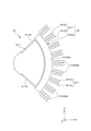
また、リング部31は、その軸がZ軸と平行となるように配置されている。このリング部31は、弾性変形可能であり、図3に示すように、振動手段4による第1の振動部51、52の振動によって、X軸方向に収縮すると共にY軸方向に伸張する第1の状態と、X軸方向に伸張すると共にY軸方向に収縮する第2の状態とに変形する。なお、以下では、第1の状態と第2の状態とを繰り返す振動を「円環振動」とも言う。
(Ring part)
The
Further, the
(第1振動部)
第1振動部51は、板状をなしている。また、第1振動部51は、第1振動部51の縁部を構成するフレーム部511と、軸部513、514を介してフレーム部511に連結するZ軸方向変位部(第1可動部、可動部)512と、櫛歯状の駆動電極515と、バネ部517を介してフレームに連結するY軸方向変位部(第2可動部、可動部)516とで構成されている。
(1st vibrating part)
The first vibrating
同様に、第1振動部52も板状をなしている。また、第1振動部52も、第1振動部52の縁部を構成するフレーム部521と、軸部523、524を介してフレーム部521に連結するZ軸方向変位部(第1可動部、可動部)522と、櫛歯状の駆動電極525と、バネ部527を介してフレームに連結するY軸方向変位部(第2可動部、可動部)526とで構成されている。
Similarly, the first vibrating
以下、第1振動部51、52について詳細に説明するが、第1振動部51、52は、互いに同様の構成であるため、以下では、第1振動部51について代表して説明し、第1振動部52については、その説明を省略する。
フレーム部511の外形は、Z軸を法線とする平面視にて、ほぼ90度の扇型をなしている。このフレーム部511には、一対の第1開口511aと、一対の第2開口511bと、第3開口511cとが形成されている。
Hereinafter, the first vibrating
The outer shape of the
各第1の開口511aには、櫛歯状の駆動電極515が複数配置されている。各駆動電極515は、Y軸方向に延在して、かつ、互いにX軸方向に離間して設けられている。この駆動電極515は、振動手段4の一部を構成するものである。
各第2開口511bの内側には、Y軸方向変位部516が設けられている。Y軸方向変位部516は、枠部516aと、枠部516aの内側に設けられた複数の検出電極516bとで構成されている。検出電極516bは、X軸方向に延在し、かつ互いにY軸方向に離間して設けられている。
A plurality of comb-shaped drive electrodes 515 are arranged in each
A
各Y軸方向変位部516は、4つのバネ部517によって、フレーム部511に接続されている。各バネ部517は、X軸方向に往復しながらY軸方向に延在する形状をなしている。各バネ部517をこのような形状とすることにより、バネ部517をY軸方向にスムーズに伸縮させることができるとともに、バネ部517のY軸方向以外の方向(すなわち、X軸方向およびZ軸方向)への変形を効果的に防止または抑制することができる。そのため、各Y軸方向変位部516をスムーズにY軸方向に変位させることができる。
Each Y-
第3開口511cの内側には、Z軸方向変位部512が設けられている。Z軸方向変位部512は、軸部513、514によってフレーム部511に連結されている。軸部513、514は、Y軸方向に延在し、かつ同軸的に設けられている。そのため、Z軸方向変位部512は、物理量センサー1にZ軸方向の応力が加わると、軸部513、514をその軸まわりに捩じり変形させつつ、軸部513、514まわりに回転する。
以上、第1振動部51について説明した。第1振動部52は、前述したように、第1振動部51と同様の構成であり、Z軸を法線とする平面視にて、リング部31の中心Oと交わるY軸に対して対称的に設けられている。但し、本発明の要件は基板2への振動漏れを最小とする構成であり、構成要素が中心OやY軸に対して完全に対称である必要はない。
A
The
(第2振動部)
第2振動部53は、板状をなしている。また、第2振動部53は、第2振動部53の縁部を構成するフレーム部531と、軸部533、534を介してフレーム部531に連結するZ軸方向変位部(第3可動部、可動部)532と、バネ部537を介してフレームに連結するX軸方向変位部(第4可動部、可動部)536とで構成されている。
同様に、第2振動部54も板状をなしている。また、第2振動部54も、第2振動部54の縁部を構成するフレーム部541と、軸部543、544を介してフレーム部541に連結するZ軸方向変位部(第3可動部、可動部)542と、バネ部547を介してフレームに連結するX軸方向変位部(第4可動部、可動部)546とで構成されている。
(2nd vibrating part)
The second vibrating
Similarly, the second vibrating
以下、第2振動部53、54について詳細に説明するが、第2振動部53、54は、互いに同様の構成であるため、以下では、第2振動部53について代表して説明し、第2振動部54については、その説明を省略する。
フレーム部531の外形は、Z軸を法線とする平面視にて、ほぼ90度の扇型をなしている。また、フレーム部531の外形は、第1振動部51、52のフレーム部511、521と同じである。このフレーム部531には、一対の第2開口531bと、第3開口531cとが形成されている。
Hereinafter, the second vibrating
The outer shape of the
各第2の開口511bの内側には、X軸方向変位部536が設けられている。X軸方向変位部536は、枠部536aと、枠部536aの内側に設けられた複数の検出電極536bとで構成されている。検出電極536bは、Y軸方向に延在して、かつ互いにX軸方向に離間して設けられている。
このようなX軸方向変位部536は、4つのバネ部537によって、フレーム部531に接続されている。各バネ部537は、Y軸方向に往復しながらX軸方向に延在する形状をなしている。各バネ部537をこのような形状とすることにより、バネ部537をX軸方向にスムーズに伸縮させることができるとともに、バネ部537のX軸方向以外の方向(すなわち、Y軸方向およびZ軸方向)への変形を効果的に防止または抑制することができる。そのため、X軸方向変位部536をスムーズにX軸方向に変位させることができる。
Inside each of the
Such an X-axis
第3開口531cの内側には、Z軸方向変位部532が設けられている。Z軸方向変位部532は、軸部533、534によってフレーム部531に連結されている。軸部533、534は、X軸方向に延在し、かつ同軸的に設けられている。そのため、Z軸方向変位部532は、物理量センサー1にZ軸方向の応力が加わると、軸部533、534をその軸まわりに捩じり変形させつつ、軸部533、534まわりに回転する。
以上、第2振動部53について説明した。第2振動部54は、前述したように、第2振動部53と同様の構成であり、Z軸を法線とする平面視にて、リング部31の中心Oと交わるX軸に対して対称的に設けられている。但し、第2振動部53、54についても前述同様、中心OやX軸に対して完全に対称である必要はない。
Inside the
The
(第1内側バネ部)
第1内側バネ部81は、第1振動部51とリング部31とを連結している。また、第1内側バネ部82は、第1振動部52とリング部31とを連結している。このような第1内側バネ部81、82は、互いに同様の構成であるため、以下では、第1内側バネ部81について代表して説明し、第1内側バネ部82については、その説明を省略する。
(1st inner spring part)
The first
第1内側バネ部81は、一対のバネ部811、812で構成されており、各バネ部811、812は、Y軸方向に往復しながらX軸方向に延在した形状をなしている。また、バネ部811、812は、Z軸を法線とする平面視にて、リング部31の中心Oと交わるX軸に対して対称的に設けられている。各バネ部811、812をこのような形状とすることにより、第1内側バネ部81を、Y軸方向およびZ軸方向への変形を抑制(規制)しつつX軸方向にスムーズに伸縮させることができる。そのため、後述するように、第1内側バネ部81をX軸方向に伸縮させつつ、第1振動部51をX軸方向にスムーズに振動させることができる。
The first
(第2内側バネ部)
第2内側バネ部83は、第2振動部53とリング部31とを連結している。また、第2内側バネ部84は、第2振動部54とリング部31とを連結している。このような第2内側バネ部83、84は、互いに同様の構成であるため、以下では、第2内側バネ部83について代表して説明し、第1内側バネ部84については、その説明を省略する。
(2nd inner spring part)
The second
第2内側バネ部83は、一対のバネ部831、832で構成されており、各バネ部831、832は、X軸方向に往復しながらY軸方向に延在した形状をなしている。また、バネ部831、832は、Z軸を法線とする平面視にて、リング部31の中心Oと交わるY軸に対して対称的に設けられている。第2内側バネ部83をこのような構成とすることにより、第2内側バネ部83を、X軸方向およびZ軸方向への変形を抑制(規制)しつつY軸方向にスムーズに伸縮させることができる。そのため、後述するように、第2内側バネ部83をY軸方向に伸縮させつつ、第2振動部53をY軸方向にスムーズに振動させることができる。
The second
(内側固定部)
内側固定部61、62、63、64は、リング部31を支持する機能を有している。このような内側固定部61、62、63、64は、それぞれ、4つの振動部51、52、53、54の内側に設けられている。内側固定部61、62、63、64をこのように配置することにより、スペースを有効活用することができ、物理量センサー1の小型化を図ることができる。また、梁71、72、73、74の長さを短くすることができるため、リング部31をより安定して支持することができる。更に、内側固定部61、62、63、64をこのように配置することにより、第1振動部51、52、第2振動部53、54のストッパーとしての役割を担わせることができる。
(Inner fixing part)
The
内側固定部61、62、63、64は、Z軸を法線とする平面視にて、リング部31の外周まわりに90度間隔で設けられている。具体的には、Z軸を法線とする平面視にて、リング部31の中心Oと交わり、X軸およびY軸のそれぞれの軸に対して45度傾いた一対の軸をJ1、J2としたとき、内側固定部61、63が軸J1上に位置し、かつリング部31を介して対向配置されている。また、内側固定部62、64が軸J2上に位置し、かつリング部31を介して対向配置されている。
言い換えれば、4つの内側固定部61、62、63、64は、X軸およびY軸の両軸に対して鏡面対象の位置に設けられている。これにより、リング部31を安定して支持することができる。
The
In other words, the four
(梁)
梁71、72、73、74は、リング部31と内側固定部61、62、63、64とを連結している。梁71は、軸J1に沿って直線状に延在し、リング部31と内側固定部61とを連結している。同様に、梁72は、軸J2に沿って直線状に延在し、リング部31と内側固定部62とを連結している。また、梁73は、軸J1に沿って直線状に延在し、リング部31と内側固定部63とを連結している。また、梁74は、軸J2上に沿って直線状に延在し、リング部31と内側固定部64とを連結している。
(Beam)
The
このような梁71、72、73、74は、それぞれ、リング部31の側面のX軸およびY軸のそれぞれの軸に対して45度傾斜した各部位(固定点、第1グループの固定点)に接続されている。この各固定点は、図3に示すように、リング部31の円環振動の節となる部位(すなわち、実質的に変位・変形が起きない部位)である。このような各固定点に梁71、72、73、74を接続することにより、梁71、72、73、74によって、リング部31の円環振動が阻害されず、かつ円環振動に起因する振動が梁71、72、73、74および固定部61、62、63、64を介して振動系構造体3の外部に漏れることが防止または抑制される。その結果、振動系構造体3の振動のQ値が高くなり、物理量センサー1の検知精度が向上する。また、振動系構造体3を効率的に振動させることができるため、振動手段4の出力を小さくすることができ、その結果、物理量センサー1の小型化を図ることができる。
また、梁71、72、73、74は、リング部31の中心Oに対する動径方向(延在方向)に動く(変形する)ことを制限されている。これにより、内側固定部61、62、63、64によってリング部31をより安定して支持することができると共に、振動漏れをより効果的に防止または抑制することができる。
Each of
Further, the
(外側固定部)
外側固定部651、652、661、662、671、672、681、682は、それぞれ、4つの振動部51、52、53、54の外側に設けられている。また、外側固定部651、652は、第1振動部51に対応して設けられており、互いにY軸方向に離間している。同様に、外側固定部661、662は、第1振動部52に対応して設けられており、互いにY軸方向に離間している。また、外側固定部671、672は、第2振動部53に対応して設けられており、互いにX軸方向に離間している。また、外側固定部681、682は、第2振動部54に対応して設けられており、互いにX軸方向に離間して設けられている。
(Outer fixing part)
The
(外側バネ部)
外側バネ部851、852、861、862、871、872、881、882は、外側固定部651、652、661、662、671、672、681、682と振動部51、52、53、54とを連結している。具体的には、外側バネ部851、852は、第1の振動部51と外側固定部651、652とを連結し、外側バネ部861、862は、第1の振動部52と外側固定部661、656とを連結し、外側バネ部871、872は、第2の振動部53と外側固定部671、672とを連結し、外側バネ部881、882は、第2の振動部54と外側固定部681、682とを連結している。
(Outer spring part)
The
外側バネ部851、852は、Y軸方向に往復しながらX軸方向に延在する形状をなしている。また、外側バネ部851、852は、リング部31の中心Oと交わるX軸に対して対称的に設けられている。
同様に、外側バネ部861、862は、Y軸方向に往復しながらX軸方向に延在する形状をなしている。また、外側バネ部861、862は、リング部31の中心Oと交わるX軸に対して対称的に設けられている。
外側バネ部871、872は、X軸方向に往復しながらY軸方向に延在する形状をなしている。また、外側バネ部871、872は、リング部31の中心Oと交わるY軸に対して対称的に設けられている。
The
Similarly, the
The
同様に、外側バネ部881、882は、X軸方向に往復しながらY軸方向に延在する形状をなしている。また、外側バネ部881、882は、リング部31の中心Oと交わるY軸に対して対称的に設けられている。但し、外側バネ部851と852、861と862、871と872、881と882は、中心OやX軸、或いはY軸に対して完全に対称であることが本発明の必須条件ではない。
以上のような振動系構造体3は、固有の共振周波数を有している。これにより、後述するように、振動系構造体3を共振モードで駆動することができ、角速度の検出精度を向上させることができる。
Similarly, the
The
-基板-
基板2は、振動系構造体3を支持するものである。図2に示すように、基板2は、板状をなしており、XY面内に設けられている。そして、基板2の上面に、振動系構造体3の内側固定部61、62、63、64および外側固定部651、652、661、662、671、672、681、682を接合することにより、振動系構造体3が基板2に固定・支持される。
-substrate-
The substrate 2 supports the
基板2と内側固定部61、62、63、64および外側固定部651、652、661、662、671、672、681、682の接合方法は、特に限定されず、直接接合や陽極接合等の各種接合方法を用いて接合してもよしい、振動系構造体3および基板2の構成材料によっては、接着剤等の支持部材を用いて接合してもよい。
また、基板2の上面(振動系構造体3と対向する側の面)には、必要に応じて凹部が形成されている。この凹部は、基板2と振動系構造体3の実際に振動する部分(例えば、第1振動部51、52および第2振動部53、54)との接触を防止する機能を有している。
このような基板2は、例えば、シリコンなどの半導体基板、ガラス、石英などの絶縁基板、或いは半導体層と絶縁層が積層してなる複合基板を各種加工技術を用いて所望の外形形状に加工することにより形成されている。これにより、物理量センサー1の構成が簡単なものとなる。
The bonding method between the substrate 2 and the
Further, a recess is formed on the upper surface of the substrate 2 (the surface on the side facing the vibration system structure 3) as needed. This recess has a function of preventing contact between the substrate 2 and the actually vibrating portion (for example, the first vibrating
In such a substrate 2, for example, a semiconductor substrate such as silicon, an insulating substrate such as glass or quartz, or a composite substrate in which a semiconductor layer and an insulating layer are laminated is processed into a desired outer shape by using various processing techniques. It is formed by that. This simplifies the configuration of the physical quantity sensor 1.
-振動手段-
振動手段4は、第1振動部51、52を互いに逆位相でX軸方向に所定の周波数(第1の周波数)で振動させる機能を有している。すなわち、振動手段4は、第1振動部51、52を互いにリング部31に接近する方向(内側)に変位させる状態と、第1振動部51、52を互いにリング部31から離間する方向(外側)に変位させる状態とを繰り返すように第1振動部51、52を振動させる。
-Vibration means-
The vibrating means 4 has a function of vibrating the first vibrating
このような振動手段4は、第1振動部51が有する駆動電極515に対応して設けられた複数の固定電極41を有している。各固定電極41は、駆動電極515を介してX軸方向に対向配置された櫛歯状の一対の電極片411、412を有している。同様に、振動手段4は、第1振動部52が有する各駆動電極525に対応して設けられた複数の固定電極42を有している。各固定電極42は、駆動電極525を介してX軸方向に対向配置された櫛歯状の一対の電極片421、422を有している。
Such a vibrating
そして、振動手段4は、図示しない電源によって、各電極片411、421と、各電極片412、422に位相が180度ずれた交番電圧を印加することにより、各駆動電極515、525と各電極片411、421との間と、各駆動電極515、525と各電極片412、422との間にそれぞれ静電力を発生させ、第1内側バネ部81、82および外側バネ部851、852、861、862をX軸方向に伸縮させつつ、第1振動部51、52が互いに逆位相でかつ所定の周波数でX軸方向に振動する。
Then, the vibrating means 4 applies an alternating voltage 180 degrees out of phase to each of the
交番電圧の周波数としては、特に限定されないが、振動系構造体3の共振周波数とほぼ等しいのが好ましい。これにより、振動系構造体3を共振モードで駆動することができるため、角速度の検出精度を向上させることができる。
第1振動部51、52が互いに逆位相に振動すると、その振動が第1内側バネ部81、82を伝達してリング部31に伝達される。すると、リング部31は、第1振動部51、52が内側に向けて変位するときに、X軸方向に収縮すると共にY軸方向に伸張するように変形し、第1振動部51、52が外側に向けて変位するときに、X軸方向に伸張すると共にY軸方向に収縮するように変形する。すなわち、リング部31は、第1振動部51、52の振動と同期して円環振動する。
The frequency of the alternating voltage is not particularly limited, but is preferably substantially equal to the resonance frequency of the
When the first vibrating
さらに、円環振動によってリング部31がX軸方向に収縮すると共にY軸方向に伸張するように変形すると、その変形によって、第2振動部53、54が共に外側に変位し、逆に、X軸方向に伸張すると共にY軸方向に収縮するように変形すると、第2振動部53、54が共に内側に変位する。すなわち、リング部31の円環振動に同期して、第2振動部53、54が互いに逆位相でY軸方向に振動する。
Further, when the
すなわち、物理量センサー1では、リング部31の円環振動を利用して、第1振動部515、52を内側へ向けて変位させつつ第2振動部53、54を外側に向けて変位させる状態と、第1振動部51、52を外側に向けて変位させつつ第2振動部53、54を内側へ変位させる状態とが繰り返されるように、振動部51、52、53、54を振動させることができる。
That is, in the physical quantity sensor 1, the ring vibration of the
リング部31の梁71、72、73、74が接続された固定点は、リング部31の円環振動の節となる部位(すなわち、実質的に変位・変形が起きない部位)である。そのため、梁71、72、73、74によってリング部31の円環振動が阻害さることがなく、かつ円環振動に起因する振動が梁71、72、73、74および固定部61、62、63、64を介して振動系構造体3の外部に漏れることが防止または抑制される。その結果、振動系構造体3の振動のQ値が高くなり、物理量センサー1の検知精度が向上する。また、振動系構造体3を効率的に振動させることができるため、振動手段4の出力を小さくすることができ、その結果、物理量センサー1の小型化を図ることができる。
また、本実施形態のような静電駆動によれば、よりスムーズかつ確実に、上記のような振動を起こすことができる。また、本実施形態では、振動手段4を各振動部51、52、53、54の内側に接続しているため、スペースを有効活用でき、物理量センサー1の小型化を図ることができる。
The fixed point to which the
Further, according to the electrostatic drive as in the present embodiment, the above-mentioned vibration can be generated more smoothly and surely. Further, in the present embodiment, since the vibrating means 4 is connected to the inside of each vibrating
-検出手段9-
検出手段9は、図4に示すように、変位トランスデューサー91、92、93、94と、回転トランスデューサー95、96、97、98とを有している。なお、図4では、説明の便宜上、物理量センサー1の構成要素の一部の図示を省略している。
変位トランスデューサー91は、第1振動部51に設けられたY軸方向変位部516と、アンカーを介して基板2に固定された固定電極911とを有している。固定電極911は、Y軸方向変位部516が有する検出電極516bに対応して複数設けられている。各固定電極911は、検出電極516bを介して対向配置された一対の電極片911a、911bを有しており、これら各電極片911a、911bは、X軸方向に延在して設けられている。
-Detecting means 9-
As shown in FIG. 4, the detecting means 9 has
The
変位トランスデューサー92は、第1振動部52に設けられたY軸方向変位部526と、アンカーを介して基板2に固定された固定電極921とを有している。固定電極921は、Y軸方向変位部526が有する検出電極526bに対応して複数設けられている。各固定電極921は、検出電極526bを介して対向配置された一対の電極片921a、921bを有しており、これら各電極片921a、921bは、X軸方向に延在して設けられている。
The displacement transducer 92 has a Y-axis
変位トランスデューサー93は、第2振動部53に設けられたX軸方向変位部536と、アンカーを介して基板2に固定された固定電極931とを有している。固定電極931は、X軸方向変位部536が有する検出電極536bに対応して複数設けられている。各固定電極931は、検出電極536bを介して対向配置された一対の電極片931a、931bを有しており、これら各電極片931a、931bは、Y軸方向に延在して設けられている。
The
変位トランスデューサー94は、第2振動部54に設けられたX軸方向変位部546と、アンカーを介して基板2に固定された固定電極941とを有している。固定電極941は、X軸方向変位部546が有する検出電極546bに対応して複数設けられている。各固定電極941は、検出電極546bを介して対向配置された一対の電極片941a、941bを有しており、これら各電極片941a、941bは、Y軸方向に延在して設けられている。
本実施形態では、これら変位トランスデューサー91、92、93、94を、振動部51、52、53、54の内側に接続しているため、装置のスペースを有効活用でき、物理量センサー1の小型化を図ることができる。
The
In the present embodiment, since these
回転トランスデューサー95は、第1振動部51に軸513、514を介して設けられたZ軸方向変位部512と、基板2に固定されZ軸方向変位部512とZ軸方向に離間して対向配置された固定電極951と、を有している。
回転トランスデューサー96は、第1振動部52に軸523、524を介して設けられたZ軸方向変位部522と、基板2に固定されZ軸方向変位部522とZ軸方向に離間して対向配置された固定電極961と、を有している。
The
The
回転トランスデューサー97は、第2振動部53に軸533、534を介して設けられたZ軸方向変位部532と、基板2に固定されZ軸方向変位部532とZ軸方向に離間して対向配置された固定電極971と、を有している。
回転トランスデューサー98は、第2振動部54に軸543、544を介して設けられたZ軸方向変位部542と、基板2に固定されZ軸方向変位部542とZ軸方向に離間して対向配置された固定電極981と、を有している。
本実施形態では、これら回転トランスデューサー95、96、97、98を、振動部51、52、53、54の内側に接続しているため、装置のスペースを有効活用でき、物理量センサー1の小型化を図ることができる。
The
The
In the present embodiment, since these
以下、このような検出手段9による角速度の検出方法について、図5、図6および図7に基づいて簡単に説明する。なお、図5、図6および図7では、説明の便宜上、物理量センサー1の構成の一部の図示を省略している。
-Z軸まわりの角速度の検出-
図5に示すように、振動手段4によって、第1振動部51、52をX軸方向に振動させつつ、第2振動部53、54をY軸方向に振動させた状態で物理量センサー1にZ軸まわりの角速度ωが加わると、X軸方向に振動する第1振動部51、52にY軸方向のコリオリ力が作用し、Y軸方向に振動する第2振動部53、54にX軸方向のコリオリ力が作用する。
Hereinafter, a method of detecting the angular velocity by such a detecting means 9 will be briefly described with reference to FIGS. 5, 6 and 7. Note that, in FIGS. 5, 6 and 7, for convenience of explanation, a part of the configuration of the physical quantity sensor 1 is not shown.
-Detection of angular velocity around the Z axis-
As shown in FIG. 5, the physical quantity sensor 1 Z in a state where the first vibrating
このようなコリオリ力が作用すると、第1振動部51では、Y軸方向変位部516がフレーム部511に対してY軸方向に変位し、これにより、検出電極516bと電極片911aの間の静電容量と、検出電極516bと電極片911bの間の静電容量とが変化し、これらの静電容量に差が生じる。同様に、第1振動部52でも、Y軸方向変位部526がフレーム部521に対してY軸方向に変位し、これにより、検出電極526bと電極片921aの間の静電容量と、検出電極516bと電極片921bの間の静電容量とが変化し、これらの静電容量に差が生じる。
When such a collior force acts, in the first vibrating
また、第2振動部53では、X軸方向変位部536がフレーム部531に対してX軸方向に変位し、これにより、検出電極536bと電極片931aの間の静電容量と、検出電極536bと電極片931bの間の静電容量とが変化し、これらの静電容量に差が生じる。同様に、第2振動部54でも、X軸方向変位部546がフレーム部541に対してX軸方向に変位し、これにより、検出電極546bと電極片941aの間の静電容量と、検出電極546bと電極片941bの間の静電容量とが変化し、これらの静電容量に差が生じる。
そして、検出手段9は、各振動部51、52、53、54で起きるこのような静電用容量の変化を検出し、その検出結果から物理量センサー1に加わるZ軸まわりの角速度を検出することができる。
Further, in the second vibrating
Then, the detection means 9 detects such a change in electrostatic capacitance that occurs in each vibrating
-X軸まわりの角速度の検出-
図6に示した斜視図のように、振動手段4によって、第1振動部51、52をX軸方向に振動させつつ、第2振動部53、54をY軸方向に振動させた状態で物理量センサー1にX軸まわりの角速度が加わると、Y軸方向に振動する第2振動部53、54にZ軸方向のコリオリ力が作用する。
-Detection of angular velocity around the X-axis-
As shown in the perspective view shown in FIG. 6, the physical quantity is in a state where the first vibrating
このようなコリオリ力が作用すると、第2振動部53では、Z軸方向変位部532が軸部533、534まわりに回転し、これにより、Z軸方向変位部532と固定電極971の間の静電容量が変化する。同様に、第2振動部54では、Z軸方向変位部542が軸部543、544まわりに回転し、これにより、Z軸方向変位部542と固定電極981の間の静電容量が変化する。
そして、検出手段9は、第2振動部53、54で起きるこのような静電用容量の変化を検出し、その検出結果から物理量センサー1に加わるX軸まわりの角速度を検出することができる。
When such a Coriolis force acts, in the second vibrating
Then, the detection means 9 can detect such a change in electrostatic capacitance that occurs in the second vibrating
-Y軸まわりの角速度の検出-
図7に示すように、振動手段4によって、第1振動部51、52をX軸方向に振動させつつ、第2振動部53、54をY軸方向に振動させた状態で物理量センサー1にY軸まわりの角速度が加わると、X軸方向に振動する第1振動部51、52にZ軸方向のコリオリ力が作用する。
-Detection of angular velocity around the Y-axis-
As shown in FIG. 7, the physical quantity sensor 1 is Y in a state where the first vibrating
このようなコリオリ力が作用すると、第1振動部51では、Z軸方向変位部512が軸部513、514まわりに回転し、これにより、Z軸方向変位部512と固定電極951の間の静電容量が変化する。同様に、第1振動部52では、Z軸方向変位部522が軸部523、524まわりに回転し、これにより、Z軸方向変位部522と固定電極961の間の静電容量が変化する。
When such a Coriolis force acts, in the first vibrating
そして、検出手段9は、第1振動部51、52で起きるこのような静電用容量の変化を検出し、その検出結果から物理量センサー1に加わるX軸まわりの角速度を検出することができる。
以上のように、物理量センサー1によれば、X軸、Y軸、Z軸の全ての軸まわりの角速度を検出することができる。そのため、小型で、利便性に優れた物理量センサー1となる。また、本実施形態では、静電型の検出手段9を用いているため、装置の小型化を図りつつ、検出精度の向上を図ることができる。
Then, the detection means 9 can detect such a change in electrostatic capacitance that occurs in the first vibrating
As described above, according to the physical quantity sensor 1, it is possible to detect the angular velocities around all the X-axis, Y-axis, and Z-axis. Therefore, the physical quantity sensor 1 is compact and has excellent convenience. Further, in the present embodiment, since the electrostatic detection means 9 is used, it is possible to improve the detection accuracy while reducing the size of the device.
なお、物理量センサー1では、変位トランスデューサー91、92が一組となって、物理量センサー1に加わるY軸方向の加速度(直線加速度)をキャンセルする機能を有している。また、変位トランスデューサー93、94が一組となって、物理量センサー1に加わるX軸方向の加速度をキャンセルする機能を有している。また、回転トランスデューサー95、96、97、98が組となって、物理量センサー1に加わるZ軸方向の加速度をキャンセルする機能を有している。
The physical quantity sensor 1 has a function of canceling the acceleration (linear acceleration) in the Y-axis direction applied to the physical quantity sensor 1 by combining the
具体的には、例えば、物理量センサー1にY軸方向に加速度が加わると、第1振動部51のY軸方向変位部516と第1振動部52のY軸方向変位部526とが共にY軸方向同じ側に変位する。このようなY軸方向変位部516、526の変位は、Z軸まわりの角速度が加わった場合の変位(すなわち、Y軸方向変位部516、526のY軸方向互いに反対側への変位)と異なっている。そのため、物理量センサー1によれば、検出電極516bと各電極片911a、911bの間の静電容量および検出電極526bと各電極片921a、921bの間の静電容量の変化から、物理量センサー1に加わる加速度を検出することができ、この角速度を検出した場合は、検出した加速度を補正処理等によって電気的にキャンセルすることができる。その結果、物理量センサー1の角速度の検出精度がより向上する。X軸方向の加速度およびZ軸方向の加速度についても同様にしてキャンセルすることができる。
Specifically, for example, when an acceleration is applied to the physical quantity sensor 1 in the Y-axis direction, the Y-
<第2実施形態>
図8は、本発明の物理量センサーの第2実施形態を示す平面図である。
本実施形態の物理量センサーについて、前述した実施形態との相違点を中心に説明し、同様の事項については、その説明を省略する。
本実施形態の物理量センサー1は、振動手段の構成が異なること以外は、前述した第1実施形態の物理量センサーと同様である。なお、図8にて、前述した第1実施形態と同様の構成には同一符号を付してある。
<Second Embodiment>
FIG. 8 is a plan view showing a second embodiment of the physical quantity sensor of the present invention.
The physical quantity sensor of the present embodiment will be described mainly on the differences from the above-described embodiment, and the description of the same matters will be omitted.
The physical quantity sensor 1 of the present embodiment is the same as the physical quantity sensor of the first embodiment described above, except that the configuration of the vibration means is different. In FIG. 8, the same reference numerals are given to the same configurations as those of the first embodiment described above.
本実施形態の物理量センサー1では、第2振動部53、54にも振動手段4が接続されている。すなわち、第2振動部53に、X軸方向に延在する複数の駆動電極535が設けられており、第2振動部54にもX軸方向に延在する複数の駆動電極545が設けられている。
また、振動手段4は、第2振動部53が有する駆動電極535に対応して設けられた複数の固定電極43を有している。各固定電極43は、駆動電極535を介してY軸方向に対向配置された櫛歯状の一対の電極片431、432を有している。同様に、振動手段4は、第2振動部54が有する各駆動電極545に対応して設けられた複数の固定電極44を有している。各固定電極44は、駆動電極545を介してY軸方向に対向配置された櫛歯状の一対の電極片441、442を有している。
In the physical quantity sensor 1 of the present embodiment, the vibrating means 4 is also connected to the second vibrating
Further, the vibrating means 4 has a plurality of fixed
そして、振動手段4は、図示しない電源によって、電極片411、421、432、442と、電極片412、422、431、441とに180度位相のずれた交番電圧を印加することにより、第1振動部51、52を互いに逆位相でX軸方向に振動させつつ、第2振動部53、54を互いに逆位相でかつ第1振動部51、52とは反対側へY軸方向に振動させる。
このような第2実施形態によっても、前述した第1実施形態と同様の効果を発揮することができる。
Then, the vibrating means 4 applies an alternating voltage 180 degrees out of phase to the
Even with such a second embodiment, the same effect as that of the first embodiment described above can be exhibited.
<第3実施形態>
図9は、本発明の物理量センサーの第3実施形態を示す平面図である。
本実施形態の物理量センサーについて、前述した実施形態との相違点を中心に説明し、同様の事項については、その説明を省略する。
本実施形態の物理量センサー1は、振動系構造体の投影形状が異なる以外は、前述した第1実施形態の物理量センサーと同様である。なお、図9にて、前述した第1実施形態と同様の構成には同一符号を付してある。
<Third Embodiment>
FIG. 9 is a plan view showing a third embodiment of the physical quantity sensor of the present invention.
The physical quantity sensor of the present embodiment will be described mainly on the differences from the above-described embodiment, and the description of the same matters will be omitted.
The physical quantity sensor 1 of the present embodiment is the same as the physical quantity sensor of the first embodiment described above, except that the projected shape of the vibration system structure is different. In FIG. 9, the same reference numerals are given to the same configurations as those of the first embodiment described above.
本実施形態の物理量センサー1では、Z軸を法線とする平面視にて、振動部51、52、53、54の外形がそれぞれ台形をなしている。そして、Z軸方向を法線とする平面視にて、振動部51、52、53、54の集合体の投影外形がほぼ矩形となっている。これにより、物理量センサー1の小型化を図ることができる。また、例えば、物理量センサー1をチップ内に搭載する場合には、チップの形状と対応するため、チップへの搭載が簡単となる。
このような第3実施形態によっても、前述した第1実施形態と同様の効果を発揮することができる。
In the physical quantity sensor 1 of the present embodiment, the outer shapes of the vibrating
Even with such a third embodiment, the same effect as that of the above-mentioned first embodiment can be exhibited.
<第4実施形態>
図10は、本発明の物理量センサーの第4実施形態を示す平面図である。
本実施形態の物理量センサーについて、前述した実施形態との相違点を中心に説明し、同様の事項については、その説明を省略する。
本実施形態の物理量センサー1は、振動手段の構成が異なること以外は、前述した第1実施形態の物理量センサーと同様である。なお、図10にて、前述した第1実施形態と同様の構成には同一符号を付してある。
<Fourth Embodiment>
FIG. 10 is a plan view showing a fourth embodiment of the physical quantity sensor of the present invention.
The physical quantity sensor of the present embodiment will be described mainly on the differences from the above-described embodiment, and the description of the same matters will be omitted.
The physical quantity sensor 1 of the present embodiment is the same as the physical quantity sensor of the first embodiment described above, except that the configuration of the vibration means is different. In FIG. 10, the same reference numerals are given to the same configurations as those of the first embodiment described above.
本実施形態の振動手段4は、圧電駆動によって、第1振動部51、52をX軸方向に振動させるように構成されている。以下では、第1振動部51について代表して説明し、第1振動部52については、その説明を省略する。
第1振動部51には、第1開口511aの内側に設けられ、基板2に固定された固定部518aと、第1開口511aの内側に設けられ、固定部518aとフレーム部511とを連結する複数の連結部518bとを有している。各連結部518bは、Y軸方向に延在して設けられていると共に、互いにX軸方向に離間して配置されている。
振動手段4は、各連結部518bに設けられた一対の圧電体素子45、46とを有している。圧電体素子45、46は、Y軸方向に延在して設けられており、かつX軸方向に離間して設けられている。
The vibrating means 4 of the present embodiment is configured to vibrate the first vibrating
The first vibrating
The vibrating means 4 has a pair of
圧電体素子45、46は、Z軸方向に対向配置された一対の電極と、一対の電極間に介在する圧電性を有する圧電体層とで構成されており、一対の電極間に電圧を印加することにより、Y軸方向に伸張または収縮する。そのため、各圧電体素子45を伸張させると共に、各圧電体素子46を収縮させると、各連結部518bが湾曲変形し、フレーム部511と接続している側の端部がリング部31側に変位し、その結果、第1振動部51が内側に変位する。反対に、各圧電体素子45を収縮させると共に、各圧電体素子46を伸張させると、各連結部518bが湾曲変形し、フレーム部511と接続している側の端部がリング部31と反対側に変位し、その結果、第1振動部51が外側に変位する。
The
構成の振動手段4では、各圧電体素子45を伸張させると共に、各圧電体素子46を収縮させる状態と、各圧電体素子45を収縮させると共に、各圧電体素子46を伸張させる状態とが交互に繰り返されるように各圧電体素子45、46に電圧を印加することにより、第1振動部51、52を互いに逆位相でX軸方向に振動させる。
このような第4実施形態によっても、前述した第1実施形態と同様の効果を発揮することができる。
In the vibrating means 4 having the configuration, a state in which each
Even with such a fourth embodiment, the same effect as that of the first embodiment described above can be exhibited.
<第5実施形態>
図11は、本発明の物理量センサーの第5実施形態を示す平面図である。
本実施形態の物理量センサーについて、前述した実施形態との相違点を中心に説明し、同様の事項については、その説明を省略する。
本実施形態の物理量センサー1は、検出手段の構成が異なること以外は、前述した第1実施形態の物理量センサーと同様である。なお、図11にて、前述した第1実施形態と同様の構成には同一符号を付してある。また、第1振動部51、52の構成は互いに同様であり、第2振動部53、54の構成は互いに同様であるため、以下では、第1振動部51と第2振動部53とについて代表して説明し、第1振動部52と第2振動部54については、その説明を省略する。
<Fifth Embodiment>
FIG. 11 is a plan view showing a fifth embodiment of the physical quantity sensor of the present invention.
The physical quantity sensor of the present embodiment will be described mainly on the differences from the above-described embodiment, and the description of the same matters will be omitted.
The physical quantity sensor 1 of the present embodiment is the same as the physical quantity sensor of the first embodiment described above, except that the configuration of the detection means is different. In FIG. 11, the same reference numerals are given to the same configurations as those of the first embodiment described above. Further, since the configurations of the first vibrating
第1振動部51は、第2開口511bの内側に設けられ、フレーム部511に対してY軸方向に変位可能な板状のY軸方向変位部519aと、Y軸方向変位部519aとフレーム部511とを連結する複数のバネ部519bとを有している。各バネ部519bは、X軸方向に延在して設けられている。
第2振動部53は、第2開口531bの内側に設けられ、フレーム部531に対してX軸方向に変位可能な板状のX軸方向変位部539aと、X軸方向変位部539aとフレーム部531とを連結する複数のバネ部539bとを有している。各バネ部539aは、Y軸方向に延在して設けられている。
The first vibrating
The second vibrating
検出手段9は、第1振動部51の各バネ部519bに設けられた一対の圧電体素子991、992を有している。圧電体素子991、992は、X軸方向に延在して、かつ互いにY軸方向に離間して設けられている。また、検出手段9は、第2振動部53の各バネ部539bに設けられた一対の圧電体素子993、994を有している。圧電体素子993、994は、Y軸方向に延在して、かつ互いにX軸方向に離間して設けられている。
The detecting means 9 has a pair of
各圧電体素子991、992、993、994は、それぞれ、Z軸方向に対向配置された一対の電極と、一対の電極間に介在する圧電性を有する圧電体層とで構成されている。このような圧電体素子991、992、993、994は、変形によって電荷を発生する性質を有しており、変形量が大きいほど大きな電荷が発生する。
そのため、物理量センサー1にZ軸まわりの角速度が加わり、第1振動部51のY軸方向変位部がバネ部519bをY軸方向に湾曲変形させつつY軸方向に変位すると、圧電体素子991、992がバネ部519bの変形量に応じた大きさの電荷を発生し、第2振動部53のX軸方向変位部が連結部539bをX軸方向に湾曲変形させつつX軸方向に変位すると、圧電体素子993、994が連結部539bの変形量に応じた大きさの電荷を発生することとなる。
検出手段9は、このような圧電体素子991、992、993、994から発生する電荷の大きさを検出することにより、Z軸まわりの角速度を検出する。
Each of the
Therefore, when the angular velocity around the Z axis is applied to the physical quantity sensor 1 and the displacement portion in the Y-axis direction of the first vibrating
The detecting means 9 detects the angular velocity around the Z axis by detecting the magnitude of the electric charge generated from such the
<第6実施形態>
図12は、本発明の物理量センサーの第6実施形態を示す平面図である。
本実施形態の物理量センサーについて、前述した実施形態との相違点を中心に説明し、同様の事項については、その説明を省略する。
本実施形態の物理量センサー1は、検出手段の構成が異なること以外は、前述した第1実施形態の物理量センサーと同様である。なお、図12にて、前述した第1実施形態と同様の構成には同一符号を付してある。また、第1振動部51、52の構成は互いに同様であり、第2振動部53、54の構成は互いに同様であるため、以下では、第1振動部51と第2振動部53とについて代表して説明し、第1振動部52と第2振動部54については、その説明を省略する。
<Sixth Embodiment>
FIG. 12 is a plan view showing a sixth embodiment of the physical quantity sensor of the present invention.
The physical quantity sensor of the present embodiment will be described mainly on the differences from the above-described embodiment, and the description of the same matters will be omitted.
The physical quantity sensor 1 of the present embodiment is the same as the physical quantity sensor of the first embodiment described above, except that the configuration of the detection means is different. In FIG. 12, the same reference numerals are given to the same configurations as those of the first embodiment described above. Further, since the configurations of the first vibrating
第1振動部51は、第2開口511bの内側に設けられ、フレーム部511に対してY軸方向に変位可能な板状のY軸方向変位部519aと、Y軸方向変位部519aとフレーム部511とを連結する複数のバネ部519bとを有している。各バネ部519bは、X軸方向に延在して設けられている。
第2振動部53は、第2開口531bの内側に設けられ、フレーム部531に対してX軸方向に変位可能な板状のX軸方向変位部539aと、X軸方向変位部539aとフレーム部531とを連結する複数のバネ部539bとを有している。各バネ部539aは、Y軸方向に延在して設けられている。
The first vibrating
The second vibrating
本実施形態の検出手段9は、第1振動部51の各バネ部519bに設けられたピエゾ抵抗部995と、第2振動部53の各バネ部539bに設けられたピエゾ抵抗部996とを有している。ピエゾ抵抗部995、996は、例えば、n型のシリコン基板を用いて振動系構造体3を形成した場合には、ボロンなどの不純物を高濃度に拡散させ、その拡散部分にp型シリコン層を形成することで形成することができる。
The detection means 9 of the present embodiment has a
ピエゾ抵抗部995、996は、変形によって抵抗値が変化する性質を有しており、変形量が大きいほど抵抗値の変化量が大きくなる。そのため、物理量センサー1にZ軸まわりの角速度が加わり、第1振動部51のY軸方向変位部がバネ部519bをY軸方向に湾曲変形させつつY軸方向に変位すると、ピエゾ抵抗部995がバネ部519bの変形量に応じた大きさの抵抗値に変化し、第2振動部53のX軸方向変位部が連結部539bをX軸方向に湾曲変形させつつX軸方向に変位すると、ピエゾ抵抗部996が連結部539bの変形量に応じた大きさの抵抗値に変化する。
検出手段9は、このようなピエゾ抵抗部995、996の抵抗値変化を検出することにより、Z軸まわりの角速度を検出する。
The
The detecting means 9 detects the angular velocity around the Z axis by detecting such a change in the resistance value of the
<第7実施形態>
図13は、本発明の物理量センサーの第7実施形態を示す平面図である。なお、図13では、説明の便宜上、物理量センサーの一部の構成の図示を省略している。
本実施形態の物理量センサーについて、前述した実施形態との相違点を中心に説明し、同様の事項については、その説明を省略する。
<7th Embodiment>
FIG. 13 is a plan view showing a seventh embodiment of the physical quantity sensor of the present invention. In FIG. 13, for convenience of explanation, the illustration of a part of the configuration of the physical quantity sensor is omitted.
The physical quantity sensor of the present embodiment will be described mainly on the differences from the above-described embodiment, and the description of the same matters will be omitted.
本実施形態の物理量センサー1は、検出手段の構成が異なること以外は、前述した第1実施形態の物理量センサーと同様である。なお、図13にて、前述した第1実施形態と同様の構成には同一符号を付してある。また、4つの振動部の構成は、Z軸まわりの配置が異なる以外は、互いに同様であるため、以下では、第1振動部51について代表して説明し、第1振動部52と第2振動部53、54については、その説明を省略する。
The physical quantity sensor 1 of the present embodiment is the same as the physical quantity sensor of the first embodiment described above, except that the configuration of the detection means is different. In FIG. 13, the same reference numerals are given to the same configurations as those of the first embodiment described above. Further, since the configurations of the four vibrating parts are the same as each other except that the arrangement around the Z axis is different, the first vibrating
第1振動部51では、Y軸方向変位部516がフレーム部511の外側に設けられており、複数のバネ部517によってフレーム部511に連結されている。このようなY軸方向変位部516は、板状の基部516cと、基部516cからX軸方向に突出した複数の検出電極516dとで構成されている。
本実施形態の検出手段9の変位トランスデューサー91は、第1振動部51に設けられたY軸方向変位部516と、アンカーを介して基板2に固定された固定電極911とを有している。固定電極911は、Y軸方向変位部516が有する検出電極516dに対応して複数設けられている。各固定電極911は、検出電極516dを介して対向配置された一対の電極片911a、911bを有しており、これら各電極片911a、911bは、X軸方向に延在して設けられている。
In the first vibrating
The
<第8実施形態>
図14は、本発明の物理量センサーの第8実施形態を示す平面図である。なお、図13では、説明の便宜上、物理量センサーの一部の構成の図示を省略している。
本実施形態の物理量センサーについて、前述した実施形態との相違点を中心に説明し、同様の事項については、その説明を省略する。
<8th Embodiment>
FIG. 14 is a plan view showing an eighth embodiment of the physical quantity sensor of the present invention. In FIG. 13, for convenience of explanation, the illustration of a part of the configuration of the physical quantity sensor is omitted.
The physical quantity sensor of the present embodiment will be described mainly on the differences from the above-described embodiment, and the description of the same matters will be omitted.
本実施形態の物理量センサー1は、検出手段の構成が異なること以外は、前述した第1実施形態の物理量センサーと同様である。なお、図14にて、前述した第1実施形態と同様の構成には同一符号を付してある。また、4つの振動部の構成は、Z軸まわりの配置が異なる以外は、互いに同様であるため、以下では、第1振動部51について代表して説明し、第1振動部52と第2振動部53、54については、その説明を省略する。
The physical quantity sensor 1 of the present embodiment is the same as the physical quantity sensor of the first embodiment described above, except that the configuration of the detection means is different. In FIG. 14, the same reference numerals are given to the same configurations as those of the first embodiment described above. Further, since the configurations of the four vibrating parts are the same as each other except that the arrangement around the Z axis is different, the first vibrating
第1振動部51では、フレーム部511の外側に設けられたZ軸まわり変位部516Aが、一対の連結バネ517Aによってフレーム部511に連結されている。また、一対の連結バネ517Aは、それぞれ、リング部31の中心Oに対する動径方向に沿って延在している。また、Z軸まわり変位部516Aは、板状の基部516Aaと、基部516Aaからリング部31の中心Oに対する動径方向に突出した複数の固定電極516Abとを有している。
In the first vibrating
このような第1振動部51では、Z軸まわりの角速度が加わった場合に生じるY軸方向のコリオリ力によって、Z軸まわり変位部516Aが、一対の連結バネ517Aを湾曲変形させつつ、Z軸まわりに回動する。このような構成によれば、Y軸方向のコリオリ力をZ軸まわりの応力に変化することができるため、Z軸まわり変位部516Aの変位量を大きくすることができる。
In such a first vibrating
本実施形態の検出手段9の回転トランスデューサー91は、第1振動部51に設けられたZ軸まわり変位部516Aと、アンカーを介して基板2に固定された固定電極911とを有している。固定電極911は、Z軸まわり変位部516Aが有する固定電極516Abに対応して複数設けられている。各固定電極911は、固定電極516Abを介して対向配置された一対の電極片911a、911bを有している。
以上説明したような各実施形態の振動片は、各種の電子機器に適用することができ、得られる電子機器は、信頼性の高いものとなる。
The
The vibrating pieces of each embodiment as described above can be applied to various electronic devices, and the obtained electronic devices are highly reliable.
ここで、本発明の振動片を備える電子機器について、図15~図17に基づき、詳細に説明する。
図15は、本発明の物理量センサーを備える電子機器を適用したモバイル型(またはノート型)のパーソナルコンピューターの構成を示す斜視図である。
この図において、パーソナルコンピューター1100は、キーボード1102を備えた本体部1104と、表示部100を備えた表示ユニット1106とにより構成され、表示ユニット1106は、本体部1104に対しヒンジ構造部を介して回動可能に支持されている。
このようなパーソナルコンピューター1100には、角速度検知手段(ジャイロセンサー)として機能する物理量センサー1が内蔵されている。
Here, the electronic device including the vibrating piece of the present invention will be described in detail with reference to FIGS. 15 to 17.
FIG. 15 is a perspective view showing the configuration of a mobile (or notebook) personal computer to which an electronic device equipped with the physical quantity sensor of the present invention is applied.
In this figure, the
Such a
図16は、本発明の物理量センサーを備える電子機器を適用した携帯電話機(PHSも含む)の構成を示す斜視図である。
この図において、携帯電話機1200は、複数の操作ボタン1202、受話口1204および送話口1206を備え、操作ボタン1202と受話口1204との間には、表示部100が配置されている。
このような携帯電話機1200には、角速度検知手段(ジャイロセンサー)として機能する物理量センサー1が内蔵されている。
FIG. 16 is a perspective view showing the configuration of a mobile phone (including PHS) to which an electronic device provided with the physical quantity sensor of the present invention is applied.
In this figure, the
Such a
図17は、本発明の物理量センサーを備える電子機器を適用したディジタルスチルカメラの構成を示す斜視図である。なお、この図には、外部機器との接続についても簡易的に示されている。
ここで、通常のカメラは、被写体の光像により銀塩写真フィルムを感光するのに対し、ディジタルスチルカメラ1300は、被写体の光像をCCD(Charge Coupled Device)などの撮像素子により光電変換して撮像信号(画像信号)を生成する。
FIG. 17 is a perspective view showing the configuration of a digital still camera to which an electronic device including the physical quantity sensor of the present invention is applied. It should be noted that this figure also briefly shows the connection with an external device.
Here, while a normal camera exposes a silver halide photographic film by the light image of the subject, the
ディジタルスチルカメラ1300におけるケース(ボディー)1302の背面には、表示部が設けられ、CCDによる撮像信号に基づいて表示を行う構成になっており、表示部は、被写体を電子画像として表示するファインダーとして機能する。
また、ケース1302の正面側(図中裏面側)には、光学レンズ(撮像光学系)やCCDなどを含む受光ユニット1304が設けられている。
A display unit is provided on the back surface of the case (body) 1302 of the
Further, on the front side (back side in the drawing) of the
撮影者が表示部に表示された被写体像を確認し、シャッターボタン1306を押下すると、その時点におけるCCDの撮像信号が、メモリ1308に転送・格納される。
また、このディジタルスチルカメラ1300においては、ケース1302の側面に、ビデオ信号出力端子1312と、データ通信用の入出力端子1314とが設けられている。そして、図示されるように、ビデオ信号出力端子1312にはテレビモニター1430が、デ-タ通信用の入出力端子1314にはパーソナルコンピューター1440が、それぞれ必要に応じて接続される。さらに、所定の操作により、メモリ1308に格納された撮像信号が、テレビモニター1430や、パーソナルコンピューター1440に出力される構成になっている。
このようなディジタルスチルカメラ1300には、角速度検知手段(ジャイロセンサー)として機能する物理量センサー1が内蔵されている。
When the photographer confirms the subject image displayed on the display unit and presses the
Further, in the
Such a
なお、本発明の振動片を備える電子機器は、図15のパーソナルコンピューター(モバイル型パーソナルコンピューター)、図16の携帯電話機、図17のディジタルスチルカメラの他にも、例えば、インクジェット式吐出装置(例えばインクジェットプリンター)、ラップトップ型パーソナルコンピューター、テレビ、ビデオカメラ、ビデオテープレコーダー、カーナビゲーション装置、ページャ、電子手帳(通信機能付も含む)、電子辞書、電卓、電子ゲーム機器、ワードプロセッサー、ワークステーション、テレビ電話、防犯用テレビモニター、電子双眼鏡、POS端末、医療機器(例えば電子体温計、血圧計、血糖計、心電図計測装置、超音波診断装置、電子内視鏡)、魚群探知機、各種測定機器、計器類(例えば、車両、航空機、船舶の計器類)、フライトシュミレーター等に適用することができる。 In addition to the personal computer (mobile personal computer) of FIG. 15, the mobile phone of FIG. 16, and the digital still camera of FIG. 17, the electronic device provided with the vibrating piece of the present invention is, for example, an inkjet ejection device (for example). Inkjet printer), laptop personal computer, TV, video camera, video tape recorder, car navigation device, pager, electronic notebook (including communication function), electronic dictionary, calculator, electronic game equipment, word processor, workstation, TV Telephones, security TV monitors, electronic binoculars, POS terminals, medical equipment (eg electronic thermometers, blood pressure monitors, blood glucose meters, electrocardiogram measuring devices, ultrasonic diagnostic devices, electronic endoscopes), fish finder, various measuring devices, instruments It can be applied to a class (for example, a vehicle, an aircraft, a ship's instrument), a flight simulator, and the like.
以上、本発明の物理量センサーを図示の実施形態に基づいて説明したが、本発明はこれに限定されるものではなく、各部の構成は、同様の機能を有する任意の構成のものに置換することができる。
また、本発明に、他の任意の構成物が付加されていてもよい。また、本発明は、前記各実施形態のうちの、任意の2以上の構成(特徴)を組み合わせたものであってもよい。
Although the physical quantity sensor of the present invention has been described above based on the illustrated embodiment, the present invention is not limited to this, and the configuration of each part may be replaced with an arbitrary configuration having the same function. Can be done.
Further, any other constituent may be added to the present invention. Further, the present invention may be a combination of any two or more configurations (features) in each of the above embodiments.
1‥‥物理量センサー 2‥‥基板 3‥‥振動系構造体 31‥‥リング部 4‥‥振動手段 41‥‥固定電極 411、412‥‥電極片 42‥‥固定電極 421、422‥‥電極片 43、44‥‥固定電極 431、432‥‥電極片 441、442‥‥電極片 45、46‥‥圧電体素子 51‥‥第1振動部 511‥‥フレーム部 511a‥‥第1開口 511b‥‥第2開口 511c‥‥第3開口 512‥‥Z軸方向変位部 513、514‥‥軸部 515‥‥駆動電極 516‥‥Y軸方向変位部 516A‥‥変位部 516Aa‥‥基部 516Ab‥‥固定電極 516a‥‥枠部 516b‥‥検出電極 516c‥‥基部 516d‥‥検出電極 517‥‥バネ部 517A‥‥一対の連結バネ 518a‥‥固定部 518b‥‥連結部 519a‥‥Y軸方向変位部 519b‥‥バネ部 52‥‥第1振動部 521‥‥フレーム部 522‥‥Z軸方向変位部 523、524‥‥軸部 525‥‥駆動電極 526‥‥Y軸方向変位部 526b‥‥検出電極 527‥‥バネ部 53‥‥第2振動部 531‥‥フレーム部 531a‥‥第1開口 531b‥‥第2開口 531c‥‥第3開口 532‥‥Z軸方向変位部 533、534‥‥軸部 535‥‥駆動電極 536‥‥X軸方向変位部 536a‥‥枠部 536b‥‥検出電極 537‥‥バネ部 539a‥‥バネ部 539b‥‥連結部 519a‥‥X軸方向変位部 519b‥‥バネ部 54‥‥第2振動部 541‥‥フレーム部 542‥‥Z軸方向変位部 543、544‥‥軸部 545‥‥駆動電極 546‥‥検出電極 546b‥‥Y軸方向延在部 547‥‥バネ部 61、62、63、64‥‥内側固定部 651、652、661、662、671、672、681、682‥‥外側固定部 71、72、73、74‥‥梁 81‥‥第1内側バネ部 811、812‥‥バネ部 82‥‥第1内側バネ部 83‥‥第2内側バネ部 831、832‥‥バネ部 84‥‥第2内側バネ部 851、852、861、862、871、872、881、882‥‥外側バネ部 9‥‥検出手段 91‥‥変位トランスデューサー 911、912‥‥固定電極 911a、911b‥‥電極片 92‥‥変位トランスデューサー 921、922‥‥固定電極 921a、921b‥‥電極片 93‥‥変位トランスデューサー 931、932‥‥固定電極 931a、931b‥‥電極片 94‥‥変位トランスデューサー 941、942‥‥固定電極 941a、941b‥‥電極片 95‥‥回転トランスデューサー 951‥‥固定電極 96‥‥回転トランスデューサー 961‥‥固定電極 97‥‥回転トランスデューサー 971‥‥固定電極 98‥‥回転トランスデューサー 981‥‥固定電極 991、992‥‥圧電体素子 993、994‥‥圧電体素子 995、996‥‥ピエゾ抵抗部 100‥‥表示部 1100‥‥パーソナルコンピューター 1102‥‥キーボード 1104‥‥本体部 1106‥‥表示ユニット 1200‥‥携帯電話機 1202‥‥操作ボタン 1204‥‥受話口 1206‥‥送話口 1300‥‥ディジタルスチルカメラ 1302‥‥ケース 1304‥‥受光ユニット 1306‥‥シャッターボタン 1308‥‥メモリ 1312‥‥ビデオ信号出力端子 1314‥‥入出力端子 1430‥‥テレビモニター 1440‥‥パーソナルコンピューター J1、J2‥‥軸
1 ‥‥ Physical quantity sensor 2 ‥‥‥
Claims (5)
基板と、
前記基板に支持され、前記基板と前記Z軸に沿ったZ軸方向に離間している構造体と、
を含み、
前記構造体は、
対をなす第1振動部及び第2振動部と、
対をなす第3振動部及び第4振動部と、
前記第1振動部及び前記第2振動部を前記X軸に沿ったX軸方向であって互い逆位相で振動させ、前記第3振動部及び前記第4振動部を前記Y軸に沿ったY軸方向であって互いに逆位相で振動させる振動手段と、
前記第1振動部に設けられている第1検出電極と、
前記第1検出電極に対して前記Y軸方向に離間し、前記基板に設けられている第1固定電極と、
前記第2振動部に設けられている第2検出電極と、
前記第2検出電極に対して前記Y軸方向に離間し、前記基板に設けられている第2固定電極と、
前記第1振動部に設けられ、前記Z軸に沿ったZ軸方向に変位する第1可動部と、
前記第1可動部と前記Z軸方向に離間し、前記基板に設けられている第3固定電極と、
前記第2振動部に設けられ、前記Z軸方向に変位する第2可動部と、
前記第2可動部と前記Z軸方向に離間し、前記基板に設けられている第4固定電極と、
前記第3振動部に設けられ、前記Z軸方向に変位する第3可動部と、
前記第3可動部と前記Z軸方向に離間し、前記基板に設けられている第5固定電極と、
前記第4振動部に設けられ、前記Z軸方向に変位する第4可動部と、
前記第4可動部と前記Z軸方向に離間し、前記基板に設けられている第6固定電極と、
前記第1振動部と前記第2振動部との間に配置され、かつ前記第3振動部と第4振動部との間に配置されている連結部と、
前記連結部を梁を介して支持し、前記基板に取り付けられている4つの支持部と、
を含み、
前記構造体の投影外形は、ほぼ矩形であることを特徴とする物理用センサー。 When the three axes orthogonal to each other are the X-axis, Y-axis, and Z-axis,
With the board
A structure supported by the substrate and separated from the substrate in the Z-axis direction along the Z-axis.
Including
The structure is
A pair of first and second vibrating parts,
A pair of 3rd and 4th vibrating parts,
The first vibrating section and the second vibrating section are vibrated in the X-axis direction along the X axis and in opposite phases to each other, and the third vibrating section and the fourth vibrating section are Y along the Y axis. A vibrating means that vibrates in the axial direction and in opposite phases to each other,
The first detection electrode provided in the first vibration unit and
With respect to the first detection electrode, the first fixed electrode provided on the substrate, separated from the first detection electrode in the Y-axis direction,
The second detection electrode provided in the second vibration unit and
A second fixed electrode provided on the substrate, separated from the second detection electrode in the Y-axis direction,
A first movable portion provided in the first vibrating portion and displaced in the Z-axis direction along the Z-axis, and a first movable portion.
A third fixed electrode, which is separated from the first movable portion in the Z-axis direction and is provided on the substrate ,
A second movable portion provided in the second vibrating portion and displaced in the Z-axis direction, and a second movable portion.
A fourth fixed electrode, which is separated from the second movable portion in the Z-axis direction and is provided on the substrate ,
A third movable portion provided in the third vibrating portion and displaced in the Z-axis direction, and a third movable portion.
A fifth fixed electrode provided on the substrate separated from the third movable portion in the Z-axis direction,
A fourth movable portion provided in the fourth vibrating portion and displaced in the Z-axis direction, and a fourth movable portion.
With the sixth fixed electrode provided on the substrate separated from the fourth movable portion in the Z-axis direction,
A connecting portion arranged between the first vibrating portion and the second vibrating portion and between the third vibrating portion and the fourth vibrating portion.
The four support portions that support the connecting portion via a beam and are attached to the substrate, and
Including
A physical sensor characterized in that the projected outer shape of the structure is substantially rectangular.
前記連結部は円弧状の梁を含むことを特徴とする物理用センサー。The connecting portion is a physical sensor characterized by including an arc-shaped beam.
前記構造体は、
第1方向に延在している第1辺と、
前記第1方向に直交する第2方向に延在している第2辺と、
前記第1辺と対向し、前記第1方向に延在している第3辺と、
前記第2辺と対向し、前記第2方向に延在している第4辺と、
を含むことを特徴とする物理用センサー。 In claim 1 or 2,
The structure is
The first side extending in the first direction and
A second side extending in the second direction orthogonal to the first direction, and
A third side facing the first side and extending in the first direction,
A fourth side facing the second side and extending in the second direction,
A physical sensor characterized by including.
前記第1振動部及び前記第2振動部の各々を前記基板に固定している複数の第1固定部と、A plurality of first fixing portions for fixing each of the first vibrating portion and the second vibrating portion to the substrate, and
前記第3振動部及び前記第4振動部の各々を前記基板の前記第1面に固定している複数の第2固定部と、A plurality of second fixing portions for fixing each of the third vibrating portion and the fourth vibrating portion to the first surface of the substrate, and
を含むことを特徴とする物理用センサー。A physical sensor characterized by containing.
Priority Applications (4)
| Application Number | Priority Date | Filing Date | Title |
|---|---|---|---|
| JP2020125059A JP7014267B2 (en) | 2020-07-22 | 2020-07-22 | Physical quantity sensors and electronic devices |
| JP2022005590A JP7215606B2 (en) | 2020-07-22 | 2022-01-18 | physical quantity sensors and electronics |
| JP2023004904A JP7552745B2 (en) | 2020-07-22 | 2023-01-17 | Physical sensors and electronic devices |
| JP2024151299A JP7794261B2 (en) | 2020-07-22 | 2024-09-03 | Physical sensors and electronic devices |
Applications Claiming Priority (1)
| Application Number | Priority Date | Filing Date | Title |
|---|---|---|---|
| JP2020125059A JP7014267B2 (en) | 2020-07-22 | 2020-07-22 | Physical quantity sensors and electronic devices |
Related Parent Applications (1)
| Application Number | Title | Priority Date | Filing Date |
|---|---|---|---|
| JP2019155522A Division JP6741133B2 (en) | 2019-08-28 | 2019-08-28 | Physical quantity sensor and electronic device |
Related Child Applications (1)
| Application Number | Title | Priority Date | Filing Date |
|---|---|---|---|
| JP2022005590A Division JP7215606B2 (en) | 2020-07-22 | 2022-01-18 | physical quantity sensors and electronics |
Publications (2)
| Publication Number | Publication Date |
|---|---|
| JP2020187133A JP2020187133A (en) | 2020-11-19 |
| JP7014267B2 true JP7014267B2 (en) | 2022-02-01 |
Family
ID=73221017
Family Applications (4)
| Application Number | Title | Priority Date | Filing Date |
|---|---|---|---|
| JP2020125059A Active JP7014267B2 (en) | 2020-07-22 | 2020-07-22 | Physical quantity sensors and electronic devices |
| JP2022005590A Active JP7215606B2 (en) | 2020-07-22 | 2022-01-18 | physical quantity sensors and electronics |
| JP2023004904A Active JP7552745B2 (en) | 2020-07-22 | 2023-01-17 | Physical sensors and electronic devices |
| JP2024151299A Active JP7794261B2 (en) | 2020-07-22 | 2024-09-03 | Physical sensors and electronic devices |
Family Applications After (3)
| Application Number | Title | Priority Date | Filing Date |
|---|---|---|---|
| JP2022005590A Active JP7215606B2 (en) | 2020-07-22 | 2022-01-18 | physical quantity sensors and electronics |
| JP2023004904A Active JP7552745B2 (en) | 2020-07-22 | 2023-01-17 | Physical sensors and electronic devices |
| JP2024151299A Active JP7794261B2 (en) | 2020-07-22 | 2024-09-03 | Physical sensors and electronic devices |
Country Status (1)
| Country | Link |
|---|---|
| JP (4) | JP7014267B2 (en) |
Citations (3)
| Publication number | Priority date | Publication date | Assignee | Title |
|---|---|---|---|---|
| JP2000180174A (en) | 1998-12-10 | 2000-06-30 | Denso Corp | Angular velocity sensor |
| WO2009062786A1 (en) | 2007-11-15 | 2009-05-22 | Robert Bosch Gmbh | Yaw rate sensor |
| WO2009156485A1 (en) | 2008-06-27 | 2009-12-30 | Sensordynamics Ag | Microgyroscope |
Family Cites Families (8)
| Publication number | Priority date | Publication date | Assignee | Title |
|---|---|---|---|---|
| DE19617666B4 (en) * | 1996-05-03 | 2006-04-20 | Robert Bosch Gmbh | Micromechanical rotation rate sensor |
| JPH10132571A (en) * | 1996-10-25 | 1998-05-22 | Murata Mfg Co Ltd | Angular speed sensor |
| JP4075022B2 (en) | 1998-06-24 | 2008-04-16 | アイシン精機株式会社 | Angular velocity sensor |
| JP2001304869A (en) * | 2000-04-21 | 2001-10-31 | Japan Aviation Electronics Industry Ltd | Ring type vibration rate sensor |
| EP1735590B1 (en) | 2004-04-14 | 2013-11-27 | Analog Devices, Inc. | Coupling apparatus for inertial sensors |
| JP4887034B2 (en) | 2005-12-05 | 2012-02-29 | 日立オートモティブシステムズ株式会社 | Inertial sensor |
| CN101910789B (en) | 2008-01-07 | 2012-02-29 | 株式会社村田制作所 | Angular velocity sensor |
| JP2010008300A (en) | 2008-06-30 | 2010-01-14 | Hitachi Ltd | Inertia sensor |
-
2020
- 2020-07-22 JP JP2020125059A patent/JP7014267B2/en active Active
-
2022
- 2022-01-18 JP JP2022005590A patent/JP7215606B2/en active Active
-
2023
- 2023-01-17 JP JP2023004904A patent/JP7552745B2/en active Active
-
2024
- 2024-09-03 JP JP2024151299A patent/JP7794261B2/en active Active
Patent Citations (3)
| Publication number | Priority date | Publication date | Assignee | Title |
|---|---|---|---|---|
| JP2000180174A (en) | 1998-12-10 | 2000-06-30 | Denso Corp | Angular velocity sensor |
| WO2009062786A1 (en) | 2007-11-15 | 2009-05-22 | Robert Bosch Gmbh | Yaw rate sensor |
| WO2009156485A1 (en) | 2008-06-27 | 2009-12-30 | Sensordynamics Ag | Microgyroscope |
Also Published As
| Publication number | Publication date |
|---|---|
| JP7794261B2 (en) | 2026-01-06 |
| JP2022046797A (en) | 2022-03-23 |
| JP2024166209A (en) | 2024-11-28 |
| JP7552745B2 (en) | 2024-09-18 |
| JP7215606B2 (en) | 2023-01-31 |
| JP2020187133A (en) | 2020-11-19 |
| JP2023052430A (en) | 2023-04-11 |
Similar Documents
| Publication | Publication Date | Title |
|---|---|---|
| CN104949666B (en) | Measuring physical, electronic equipment and moving body | |
| US9470525B2 (en) | Gyro sensor and electronic apparatus | |
| CN104034323B (en) | Gyrosensor, electronic equipment and moving body | |
| JP6061064B2 (en) | Gyro sensor and electronic equipment | |
| CN103363981B (en) | Gyrosensor and electronic equipment | |
| JP5652117B2 (en) | Physical quantity sensor and electronic equipment | |
| JP5821995B2 (en) | Physical quantity sensor and electronic equipment | |
| JP5652112B2 (en) | Physical quantity sensor and electronic equipment | |
| JP7014267B2 (en) | Physical quantity sensors and electronic devices | |
| JP6245459B2 (en) | Gyro sensor and electronics | |
| JP6070920B2 (en) | Gyro sensor and electronics | |
| JP6394739B2 (en) | Physical quantity sensor and electronic equipment | |
| JP2013234904A (en) | Gyro sensor and manufacturing method for the gyro sensor, and electronic apparatus | |
| JP6741133B2 (en) | Physical quantity sensor and electronic device | |
| JP6579244B2 (en) | Physical quantity sensor and electronic equipment | |
| JP2016206207A (en) | Gyro sensor and electronic apparatus | |
| JP6149910B2 (en) | Physical quantity sensor and electronic equipment | |
| JP6319610B2 (en) | Gyro sensor, method for manufacturing the same, and electronic device | |
| JP2015137991A (en) | Functional elements, sensor device, electronic apparatus and movable body | |
| JP2015099115A (en) | Angular velocity sensor, electronic device, and mobile entity | |
| JP2013234913A (en) | Gyro sensor and electronic apparatus | |
| JP2013145189A (en) | Gyro sensor and electronic apparatus | |
| JP2015178998A (en) | Angular velocity sensor, electronic device and moving object | |
| JP2016170140A (en) | Vibration piece, gyro sensor, electronic apparatus, and mobile body | |
| JP2015132495A (en) | Functional element, electronic device, electronic device, and moving object |
Legal Events
| Date | Code | Title | Description |
|---|---|---|---|
| A521 | Request for written amendment filed |
Free format text: JAPANESE INTERMEDIATE CODE: A523 Effective date: 20200819 |
|
| A621 | Written request for application examination |
Free format text: JAPANESE INTERMEDIATE CODE: A621 Effective date: 20200819 |
|
| A977 | Report on retrieval |
Free format text: JAPANESE INTERMEDIATE CODE: A971007 Effective date: 20210616 |
|
| A131 | Notification of reasons for refusal |
Free format text: JAPANESE INTERMEDIATE CODE: A131 Effective date: 20210706 |
|
| A521 | Request for written amendment filed |
Free format text: JAPANESE INTERMEDIATE CODE: A523 Effective date: 20210903 |
|
| RD04 | Notification of resignation of power of attorney |
Free format text: JAPANESE INTERMEDIATE CODE: A7424 Effective date: 20210915 |
|
| RD03 | Notification of appointment of power of attorney |
Free format text: JAPANESE INTERMEDIATE CODE: A7423 Effective date: 20211108 |
|
| TRDD | Decision of grant or rejection written | ||
| A01 | Written decision to grant a patent or to grant a registration (utility model) |
Free format text: JAPANESE INTERMEDIATE CODE: A01 Effective date: 20211221 |
|
| A61 | First payment of annual fees (during grant procedure) |
Free format text: JAPANESE INTERMEDIATE CODE: A61 Effective date: 20220103 |
|
| R150 | Certificate of patent or registration of utility model |
Ref document number: 7014267 Country of ref document: JP Free format text: JAPANESE INTERMEDIATE CODE: R150 |