JP7006891B2 - refrigerator - Google Patents
refrigerator Download PDFInfo
- Publication number
- JP7006891B2 JP7006891B2 JP2016170670A JP2016170670A JP7006891B2 JP 7006891 B2 JP7006891 B2 JP 7006891B2 JP 2016170670 A JP2016170670 A JP 2016170670A JP 2016170670 A JP2016170670 A JP 2016170670A JP 7006891 B2 JP7006891 B2 JP 7006891B2
- Authority
- JP
- Japan
- Prior art keywords
- transparent plate
- plate material
- heat insulating
- refrigerator
- box
- Prior art date
- Legal status (The legal status is an assumption and is not a legal conclusion. Google has not performed a legal analysis and makes no representation as to the accuracy of the status listed.)
- Active
Links
Images


Landscapes
- Refrigerator Housings (AREA)
- Charge And Discharge Circuits For Batteries Or The Like (AREA)
- Devices That Are Associated With Refrigeration Equipment (AREA)
Description
本発明は、貯蔵室に貯蔵された被貯蔵物を外部上方から視認することができる冷蔵庫およびその製造方法に関する。 The present invention relates to a refrigerator capable of visually recognizing the stored object stored in the storage chamber from above the outside and a method for manufacturing the same.
一般的な冷蔵庫は、前方に開口を有する貯蔵室を形成する断熱箱体と、この開口を閉鎖する断熱扉を有する。また、断熱箱体は、鋼板からなる外箱と、合成樹脂からなり外箱の内部に配置される内箱と、外箱と内箱との間に形成される間隙に充填される断熱材とから構成されている。そして、前方の開口を塞ぐ断熱扉も同様の断熱構造とされている。従って、一般的な冷蔵庫に於いては、断熱扉を閉じた状態では貯蔵室の内部を外部から視認することはできず、貯蔵室の内部を確認するためには断熱扉を開き、前方から貯蔵室を覗く必要があった。 A typical refrigerator has an insulating box that forms a storage chamber with an opening in front and an insulating door that closes this opening. Further, the heat insulating box body is an outer box made of steel plate, an inner box made of synthetic resin and arranged inside the outer box, and a heat insulating material filled in a gap formed between the outer box and the inner box. It is composed of. The heat insulating door that closes the front opening has the same heat insulating structure. Therefore, in a general refrigerator, the inside of the storage room cannot be visually recognized from the outside when the heat insulating door is closed, and in order to check the inside of the storage room, the heat insulating door is opened and stored from the front. I had to look into the room.
一方、特許文献1には、扉を透過して冷蔵庫の内部を視認することができる冷蔵庫が記載されている。この冷蔵庫では、本体キャビネットの前方を塞ぐ断熱扉をガラスから構成することで、断熱扉を開動作せずとも、閉められた状態の断熱扉を透過して本体キャビネットの内部を視認することができる。
On the other hand,
しかしながら、特許文献1に記載された冷蔵庫では、断熱扉がガラスから構成されることで、断熱扉を開くこと無く、冷蔵庫の内部に貯蔵された食料等を前方から視認することができるものの、冷蔵庫の内部を前方以外の方向から視認することはできなかった。
However, in the refrigerator described in
特に、リビング等の居住スペースに配置される小型の冷蔵庫の場合、使用者は冷蔵庫を上方から見下ろすので、冷蔵庫の前面に取り付けられた透明扉を介して冷蔵庫の内部を確認することは簡単ではなかった。 In particular, in the case of a small refrigerator placed in a living space such as a living room, the user looks down on the refrigerator from above, so it is not easy to check the inside of the refrigerator through the transparent door attached to the front of the refrigerator. rice field.
本発明は、上記の事情に鑑みてなされたものであり、その目的とするところは、扉を開けずとも内部の被貯蔵物を上方から視認することができる冷蔵庫およびその製造方法を提供することにある。 The present invention has been made in view of the above circumstances, and an object of the present invention is to provide a refrigerator capable of visually recognizing an internal stored object from above without opening a door and a method for manufacturing the same. It is in.
本発明の冷蔵庫は、貯蔵室が内部に形成された断熱箱体と、前記断熱箱体の前方開口を塞ぐ断熱扉と、を備え、前記断熱扉を開状態とすることで、前記断熱箱体の前面側から貯蔵品を出し入れすることが可能な冷蔵庫であり、金属から成る外箱と、前記外箱の内部に配置された内箱と、前記外箱と前記内箱との間に充填された断熱材と、を有する前記断熱箱体と、前記内箱の上面および前記外箱の上面を開口することで形成された開口部と、前記開口部を塞ぐ透明板材と、被覆枠部と、を具備し、前記被覆枠部は、前記透明板材を支持し、且つ、合成樹脂から成り、更に、前記被覆枠部は、前記外箱の側面と、前記内箱の側面との間隙を上方から塞ぎ、更にまた、前記被覆枠部は、前記外箱の後面と、前記外箱の前記後面よりも後方に配置されるカバーとの間隙を、上方から塞ぐことを特徴とする。
The refrigerator of the present invention includes a heat insulating box body having a storage chamber formed inside and a heat insulating door that closes the front opening of the heat insulating box body, and the heat insulating box body is opened by opening the heat insulating box body. It is a refrigerator that can take in and out stored items from the front side of the box, and is filled between the outer box made of metal , the inner box arranged inside the outer box, and the outer box and the inner box. The heat insulating box body having the heat insulating material, an opening formed by opening the upper surface of the inner box and the upper surface of the outer box, a transparent plate material closing the opening, and a covering frame portion. The covering frame portion supports the transparent plate material and is made of synthetic resin , and the covering frame portion further provides a gap between the side surface of the outer box and the side surface of the inner box from above. Further, the covering frame portion is characterized in that the gap between the rear surface of the outer box and the cover arranged behind the rear surface of the outer box is closed from above .
更に本発明は、前記透明板材は、第1透明板材と、前記第1透明板材の上方に配置される第2透明板材と、前記第2透明板材の上方に配置される第3透明板材を有し、前記第1透明板材と前記第2透明板材との間には、枠状の第1スペーサ枠部が配置され、前記第2透明板材と、前記第3透明板材との間には、枠状の第2スペーサ枠部が配置されることを特徴とする。
Further, in the present invention, the transparent plate material includes a first transparent plate material, a second transparent plate material arranged above the first transparent plate material, and a third transparent plate material arranged above the second transparent plate material. A frame-shaped first spacer frame portion is arranged between the first transparent plate material and the second transparent plate material, and a frame is placed between the second transparent plate material and the third transparent plate material. It is characterized in that a second spacer frame portion having a shape is arranged .
また、本発明の冷蔵庫では、前記貯蔵室の冷凍機能を操作するタッチパネル式の操作部を、前記透明板材の近傍に配置することを特徴とする。 Further, the refrigerator of the present invention is characterized in that a touch panel type operation unit for operating the freezing function of the storage chamber is arranged in the vicinity of the transparent plate material.
また、本発明の冷蔵庫では、携帯機器を無接点方式で充電する充電ユニットを前記透明板材の近傍に配置することを特徴とする。 Further, the refrigerator of the present invention is characterized in that a charging unit for charging a mobile device in a non-contact manner is arranged in the vicinity of the transparent plate material.
本発明の冷蔵庫の製造方法は、外箱の内部に内箱を組み込む工程と、前記外箱と前記内箱との間の間隙に断熱材を充填する工程と、を具備し、前記組み込む工程では、前記内箱および前記外箱の上面側に形成された開口部を透明板材で塞ぐと共に、前記外箱と前記内箱の間の前記間隙を被覆枠部で上方から塞ぎ、前記充填する工程では、前記外箱の底面および側面と、前記内箱の底面および側面との間を、前記被覆枠部で塞いだ状態で、前記断熱材を充填させることを特徴とする。
The method for manufacturing a refrigerator of the present invention includes a step of incorporating an inner box inside the outer box and a step of filling a heat insulating material in a gap between the outer box and the inner box. In the step of closing the inner box and the openings formed on the upper surface side of the outer box with a transparent plate material, and closing the gap between the outer box and the inner box from above with a covering frame portion, and filling the inner box. It is characterized in that the heat insulating material is filled in a state where the space between the bottom surface and the side surface of the outer box and the bottom surface and the side surface of the inner box is closed by the covering frame portion .
本発明の冷蔵庫は、貯蔵室が内部に形成された断熱箱体と、前記断熱箱体の前方開口を塞ぐ断熱扉と、を備え、前記断熱扉を開状態とすることで、前記断熱箱体の前面側から貯蔵品を出し入れすることが可能な冷蔵庫であり、金属から成る外箱と、前記外箱の内部に配置された内箱と、前記外箱と前記内箱との間に充填された断熱材と、を有する前記断熱箱体と、前記内箱の上面および前記外箱の上面を開口することで形成された開口部と、前記開口部を塞ぐ透明板材と、被覆枠部と、を具備し、前記被覆枠部は、前記透明板材を支持し、且つ、合成樹脂から成り、更に、前記被覆枠部は、前記外箱の側面と、前記内箱の側面との間隙を上方から塞ぎ、更にまた、前記被覆枠部は、前記外箱の後面と、前記外箱の前記後面よりも後方に配置されるカバーとの間隙を、上方から塞ぐことを特徴とする。従って、貯蔵室に収納された被貯蔵物を、断熱扉を開動作すること無く、断熱箱体の上面に配置された透明板材を介して外側から視認することができる。
The refrigerator of the present invention includes a heat insulating box body having a storage chamber formed inside and a heat insulating door that closes the front opening of the heat insulating box body, and the heat insulating box body is opened by opening the heat insulating box body. It is a refrigerator that can take in and out stored items from the front side of the box, and is filled between the outer box made of metal , the inner box arranged inside the outer box, and the outer box and the inner box. The heat insulating box body having the heat insulating material, an opening formed by opening the upper surface of the inner box and the upper surface of the outer box, a transparent plate material closing the opening, and a covering frame portion. The covering frame portion supports the transparent plate material and is made of synthetic resin , and the covering frame portion further provides a gap between the side surface of the outer box and the side surface of the inner box from above. Further, the covering frame portion is characterized in that the gap between the rear surface of the outer box and the cover arranged behind the rear surface of the outer box is closed from above . Therefore, the stored object stored in the storage chamber can be visually recognized from the outside through the transparent plate material arranged on the upper surface of the heat insulating box without opening the heat insulating door.
また、本発明の冷蔵庫では、前記透明板材は、前記内箱の前記開口部の上方に配置されて可視光線を透過させる透明領域と、前記内箱と前記外箱との間隙の上方に配置されて前記可視光線を透過させない非透明領域を有することを特徴とする。従って、内箱の開口部の上方に透明領域を配置することで、透明領域を介して貯蔵室の内部を視認することができ、内箱と外箱との間隙の上方に非透明領域を配置することで、間隙に配置される各種部材を隠して意匠的な外観性を向上することができる。 Further, in the refrigerator of the present invention, the transparent plate material is arranged above the transparent region arranged above the opening of the inner box and transmitting visible light, and above the gap between the inner box and the outer box. It is characterized by having a non-transparent region that does not allow the visible light to pass through. Therefore, by arranging the transparent area above the opening of the inner box, the inside of the storage chamber can be visually recognized through the transparent area, and the non-transparent area is arranged above the gap between the inner box and the outer box. By doing so, it is possible to conceal various members arranged in the gap and improve the design appearance.
また、本発明の冷蔵庫では、携帯機器を無接点方式で充電する充電ユニットを前記透明板材の近傍に配置することを特徴とする。従って、冷蔵庫を使用する使用者は、携帯機器を簡易な方法で充電することができるようになる。 Further, the refrigerator of the present invention is characterized in that a charging unit for charging a mobile device in a non-contact manner is arranged in the vicinity of the transparent plate material. Therefore, the user who uses the refrigerator can charge the portable device by a simple method.
本発明の冷蔵庫の製造方法は、外箱の内部に内箱を組み込む工程と、前記外箱と前記内箱との間の間隙に断熱材を充填する工程と、を具備し、前記組み込む工程では、前記内箱および前記外箱の上面側に形成された開口部を透明板材で塞ぐと共に、前記外箱と前記内箱の間の前記間隙を被覆枠部で上方から塞ぎ、前記充填する工程では、前記外箱の底面および側面と、前記内箱の底面および側面との間を、前記被覆枠部で塞いだ状態で、前記断熱材を充填させることを特徴とする。従って、本発明の冷蔵庫は、上面側に透明板材が配設されることで断熱箱体の構成が比較的複雑であるが、内箱および外箱の開口部および両者の間の間隙を上方から塞いでから、この間隙に断熱材を充填させることで、比較的簡易な方法で断熱箱体を製造することができる。
The method for manufacturing a refrigerator of the present invention includes a step of incorporating an inner box inside the outer box and a step of filling a heat insulating material in a gap between the outer box and the inner box. In the step of closing the inner box and the openings formed on the upper surface side of the outer box with a transparent plate material, and closing the gap between the outer box and the inner box from above with a covering frame portion, and filling the inner box. It is characterized in that the heat insulating material is filled in a state where the space between the bottom surface and the side surface of the outer box and the bottom surface and the side surface of the inner box is closed by the covering frame portion . Therefore, in the refrigerator of the present invention, the structure of the heat insulating box is relatively complicated because the transparent plate material is arranged on the upper surface side, but the openings of the inner box and the outer box and the gap between them are formed from above. By filling the gap with a heat insulating material after closing the gap, a heat insulating box can be manufactured by a relatively simple method.
以下、本発明の実施形態に係る冷蔵庫10を図面に基づき詳細に説明する。以下の説明では、同一の構成を有する部位には同一の符号を付し、繰り返しの説明は省略する。また、以下の説明では、上下前後左右の各方向を適宜使用するが、左右とは冷蔵庫10を正面から見た場合を示している。
Hereinafter, the
図1を参照して、本形態の冷蔵庫10の概略構成を説明する。図1(A)は冷蔵庫10を前方から見た斜視図であり、図1(B)は冷蔵庫10を後方から見た斜視図である。
The schematic configuration of the
図1(A)を参照して、冷蔵庫10は、その容量が例えば100リットル程度の比較的小型のものであり、例えばリビングや寝室に配置して補助的に使用されるものである。冷蔵庫10は断熱箱体11を有し、断熱箱体11の内部には上段からワイン室20および冷蔵室21が形成されている。ワイン室20は、被貯蔵物としてのワインを倒した状態で複数本収納できる容積を有しており、ワインやワイン以外の食品等が保存され、0℃以上20℃以下に冷却される。冷蔵室21は、ワイン以外のビール等の飲料や食品等が保存され、例えば0℃以上10℃以下に冷却される。
With reference to FIG. 1 (A), the
ワイン室20の前方開口は、断熱性を有する引き出し式の断熱扉12で閉鎖されており、断熱扉12を前方に引き出すことで、倒されている状態のワインを前方に取り出すことができる。
The front opening of the
冷蔵室21の前方開口は、引き出し式の断熱扉13で閉鎖されており、断熱扉13を引き出して開くことで、冷蔵室21の前方開口から食品等の出し入れを行うことができる。
The front opening of the
本形態では、冷蔵庫10の上面を、透明な部材から成る透明板材14で構成している。透明板材14は、後述するように、断熱箱体11の上面に形成された開口部を上方から閉鎖し、可視光を透過させるガラスや合成樹脂から成る。また、透明板材14とワイン室20との間には遮光性材料である断熱発泡体が充填されていない。従って、透明板材14を透過してワイン室20に貯蔵されたワインを上方から視認することができる。
In this embodiment, the upper surface of the
透明板材14は、中央部分に形成された四角形状の透明領域15と、周辺部分に形成された枠形状の非透明領域16とから形成されている。透明領域15は、後述する断熱箱体11の開口部の上方に配置され、可視光線を透過させる。透明領域15を経由してワイン室20に収納されたワインを視認することができる。非透明領域16は、その下面が塗装処理されることで非透明とされている。そのようにすることで、非透明領域16の下方に形成される他部材を隠し、意匠的な外観性を向上することができる。
The
尚、図1(B)に示すように、冷蔵庫10の後面側のカバーを開口することで複数の開口部18が形成されている。開口部18からは、冷凍サイクルの凝縮器等により加熱された空気が外部に放出される。
As shown in FIG. 1B, a plurality of
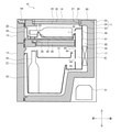
図2の側面断面図を参照して、本形態の冷蔵庫10の構造を更に説明する。冷蔵庫10の本体である断熱箱体11は、鋼板等の板材料から成る外箱24と、外箱24の内側に配置された合成樹脂板から成る内箱23と、外箱24と内箱23との間に形成される間隙に充填された硬質ウレタン等から成る断熱材25と、から構成されている。
The structure of the
内箱23の上面部には開口部が形成されており、外箱24の上面も開口部が形成されており、これらの開口部は、上方から透明板材14等で閉鎖されている。透明板材14等が開口部を塞ぐ構成は後述する。
An opening is formed in the upper surface of the
上記したように、内箱23の内部空間として形成される貯蔵室は、上段のワイン室20と下段の冷蔵室21に分割されており、ワイン室20と冷蔵室21とは断熱仕切体38で仕切られている。ワイン室20には、断熱扉12と共に外部に引き出し可能な収納容器50が配置されており、収納容器50の内部に配設された固定容器53にワイン54は載置されている。また、収納容器50および固定容器53は、下方から照射される光を上方に透過させる透明な合成樹脂から構成される。
As described above, the storage chamber formed as the internal space of the
収納容器50の下方には、LED29および導光板26が配置されており、LED29および導光板26は上方から保護カバーで被覆されている。かかる構成により、LED29から発せられた光を周囲に向かって拡散させ、均一に光を上方に向かって照射することができる。ワイン54を下方から照らすことで、冷蔵庫10が配置される部屋の照明が暗い場合であっても、使用者は、透明板材14を介してワイン室20に収納されたワイン54の銘柄等を視認することができる。また、LED29でワイン54を下方から照らすことで、視覚的に高級感を醸し出すこともできる。
An
冷蔵室21には、前方に向かって引き出し可能な収納容器51、52が配置されている。冷蔵室21の室内温度は、上記したワイン室20よりも低温であるため、収納容器51、52には、ビールなどの飲料や食品等を収納することができる。
In the
上記した各貯蔵室の奥側には、合成樹脂板からなる仕切板45、46で仕切られた送風室41および冷却室40が形成されている。冷却室40には、各貯蔵室に送風される冷気を冷却するための蒸発器30が内蔵されている。蒸発器30は、圧縮機31、図示しない凝縮器、図示しない膨張手段と冷媒配管を介して接続されることで、蒸気圧縮式冷凍サイクルを形成している。また、図示しない制御装置により、蒸気圧縮式冷凍サイクルの動作は制御されている。送風室41は、冷却室40で冷却されて各貯蔵室に送風される冷気が一旦流入し、送風路として機能している。
On the back side of each of the above-mentioned storage chambers, a
冷却室40を前方で区切る仕切板46には、冷却室40の内部で冷却された冷気を送風する送風機47が取り付けられている。また、送風室41の前方を仕切る仕切板45には、吹出口42、44および帰還口43が形成されている。吹出口42からはワイン室20に向けて冷気が吹き出され、吹出口44からは冷蔵室21に向けて冷気が吹き出される。冷蔵室21を冷却した冷気は、帰還口43から冷却室40に帰還する。ワイン室20を冷却した冷気は、ここでは図示しない帰還口を経由して、冷却室40に帰還する。
A
上記構成の冷蔵庫10の動作は次のとおりである。各貯蔵庫の温度を計測している温度センサの出力に基づき制御装置が圧縮機31を運転すると、蒸発器30が冷却室40内部の空気を冷却する。冷却室40の内部で冷却された冷気は、制御装置の指示に基づいて回転する送風機47で、各貯蔵室に送風される。具体的には、送風機47で送風された冷気は、冷却室40の前方に形成された送風室41に送風された後に、吹出口42を経由してワイン室20に送風される。ワイン室20を冷却した冷気は、ここでは図示しない帰還口を経由して、冷却室40に帰還する。送風室41に流入した冷気の一部は、吹出口44を介して吹出口44から冷蔵室21に送風される。冷蔵室21を冷却した冷気は、帰還口43を経由して冷却室40に帰還する。このような経路により、各貯蔵庫を冷気が循環することで、各貯蔵庫の室内温度が所定の温度に達したら、制御装置は圧縮機31および送風機47の運転を停止する。
The operation of the
また、上記のように蒸発器30による冷気の冷却を続けると、蒸発器30で着霜が進行し、着霜により熱交換および送風の効率が低下するので、制御装置の指示に基づいて定期的に除霜行程を行っている。更に、制御装置で開閉される図示しないダンパで冷気の送風量を調整してもよい。
Further, if the cooling of the cold air by the
また、冷蔵庫10の上面前方側には、冷蔵庫10の上面より操作可能なタッチパネル式の操作部64が配置されており、使用者が操作部64を操作することでLED29を発光させ、ワイン室20に収納されたワイン54を照らし出すことができる。また、使用者が操作部64を操作することで、冷蔵庫10の各貯蔵室の冷却温度等を調整することもできる。
Further, on the front side of the upper surface of the
更に、冷蔵庫10の上面後方側には、スマートフォンなどの携帯機器を無接点方式で充電することができる充電ユニット60が配設されている。このようにすることで、冷蔵庫10の近傍に配置されたベッドやソファで休息する使用者が有する携帯機器を、冷蔵庫10の天面に置いて簡易に充電ユニット60で充電することができる。
Further, on the rear side of the upper surface of the
図3を参照して、上記した冷蔵庫10を構成する各部材の形状等を詳述する。ここでは、冷蔵庫10を構成する各構成部材を上下方向に分離して示している。
With reference to FIG. 3, the shape and the like of each member constituting the
通常の冷蔵庫では、内箱の上面と外箱の上面との間隙には全体的に断熱材を充填するが、本形態では、冷蔵庫の内部を上方から視認することを可能とするために、外箱24および内箱23の上面に開口部を形成し、この開口部が形成された部分に下記する透明板材14等を配設している。
In a normal refrigerator, the gap between the upper surface of the inner box and the upper surface of the outer box is entirely filled with a heat insulating material, but in this embodiment, the inside of the refrigerator can be visually recognized from above. An opening is formed on the upper surfaces of the
具体的には、先ず、内箱23の上面を開口することで、略四角形形状の開口部80が形成されおり、ここでは図示しない外箱24の上面も同様に後述する開口部81が形成されている。そして、内箱23および外箱24の間隙は、上方から被覆枠部34で閉鎖されている。被覆枠部34は、枠状に成形された合成樹脂板から成る。被覆枠部34の前方部分には、使用者が操作するための操作部64が配置され、操作部64が収納される部分の被覆枠部34は下方からカバー部材36が嵌め込まれる。また、被覆枠部34の後方部分には、携帯機器を充電するための充電ユニット60が配置され、この充電ユニット60が配置される部分の被覆枠部34は後方からカバー部材37で被覆される。
Specifically, first, an
内箱23の上面には、下方から被覆枠部35が嵌め込まれている。被覆枠部35は、被覆枠部34を塞ぎ、内箱23の内部に形成される貯蔵室の気密性を確保する。
A
被覆枠部34は、内箱23の開口部80に対応した箇所に、開口部48を有しており、この開口部48に後述する透明板材33等が収納される。具体的には、被覆部材の開口部48には、下方から、透明板材33、スペーサ枠部27、透明板材32、スペーサ枠部28が配設される。透明板材32、33は、可視光線を透過させるガラスまたは透明合成樹脂からなり、平面視での大きさは、開口部48よりも若干小さい程度である。スペーサ枠部27、28は、平面視で透明板材32、33と同等の大きさの合成樹脂などから成る枠状の部材であり、透明板材32、33同士の間に間隙を確保するための部材である。透明板材32、33同士の間に間隙を確保することで、この間隙に存在する空気が断熱材の如く機能し、上記したワイン室20を断熱することができる。
The
スペーサ枠部28の上方には、被覆枠部34の上面を覆うように透明板材14が配置される。透明板材14の平面視での大きさは、被覆枠部34と略同一または、被覆枠部34よりも若干大きい程度である。透明板材14は、ガラスや透明な合成樹脂から成る。
Above the
上記のように、内箱23の開口部80の上方に、複数の透明板材33、32、14を積層配置することで、内箱23の内部に形成されるワイン室20を上方から視認可能とすると共に、ワイン室20の断熱性を確保することができる。
As described above, by laminating a plurality of
図4を参照して、上記した透明板材33、32、14が配置される構成を更に詳述する。図4は、透明板材33、32、14の前方端部およびその周辺部を示す断面図である。この図を参照して、上記したように、透明板材33、32、14の間に、スペーサ枠部27、28を配置することで、透明板材33と透明板材32との間、透明板材32と透明板材14との間に、所定の厚みの間隙を形成している。
With reference to FIG. 4, the configuration in which the above-mentioned
ここで、透明板材33、32、14と他の部材との接合部分は接着剤などで封止されてもよい。例えば、透明板材33、32、14とスペーサ枠部27、28との間は、接着剤などで封止されてもよい。
Here, the joint portion between the
透明板材32等が被覆枠部34に組み込まれる構成を説明する。先ず、被覆枠部34の下面側は、内箱23および被覆枠部35で覆われ、これらの部材で矩形閉断面が構成されている。被覆枠部34の前方内壁には、所定形状に曲折加工された鋼板から成る前板17が配設されている。前板17の前方部分は、被覆枠部34と接合するための平坦面とされ、前板17の後方部分は、下方に向かって開く開口形状とされている。断熱扉12側のパッキンに内蔵された図示しないマグネットが、鋼鉄製の前板17に磁力で引き寄せられることで、断熱扉12と断熱箱体11との密着性が強化されている。また、内箱23の前方端部が前板17の開口部分に嵌合することで、内箱23は被覆枠部34に対して組み付けられている。更に、前板17には冷媒配管19が内蔵されており、冷媒配管19から熱が発せられることで、断熱扉12に接する部分の断熱箱体11に結露が発生することを抑止している。
A configuration in which the
被覆枠部34、被覆枠部35および内箱23の下方後方端部は、後方に向かって突出する鈎状部57を形成しており、透明板材32、33の前方端部はこの鈎状部57で下方から支持されている。このような支持構造は、透明板材32、33の左方端部、右方端部および後方端部においても同様である。また、透明板材33、スペーサ枠部27、透明板材32およびスペーサ枠部28は、被覆枠部34の開口部48の内部、即ち紙面上では被覆枠部34の右方部分に収納される。一方、最上部に配置される透明板材14は、被覆枠部34の開口部48および被覆枠部34の上面を覆っている。
The lower rear end portion of the
上記のように、被覆枠部35は、接着、締結、嵌め込み等の接合方法で、内箱23に対して接合されている。また、被覆枠部35は、単体の部材として構成されても良いし、複数の部材から構成されてもよい。更に、透明板材14の前端付近の下方には、操作部64が配置されている。使用者は、操作部64の上方部分の透明板材14を接触することで、操作部64に対して指示を与えることができる。
As described above, the
図5を参照して、ワイン54を収納する構成を説明する。図5では、ワイン室20に収納される収納容器50を断熱扉12と共に示している。断熱扉12の左右方向両端部には、後方側に向かって伸びるレール部61が取り付けられている。レール部61は、図2に示した内箱23の側面を窪ませて形成した図示しないレール受部により支持されている。断熱扉12を断熱箱体11から前方側に引き出すと、収納容器50は収納容器50と共に前方側に移動する。
A configuration for storing the
固定容器53は、収納容器50の内部に配置され、ワイン54の位置を固定する。固定容器53の前方側には、上方に向かって突出する突出部58が左右方向に伸びるように形成されており、突出部58の上端部分を略半円状に切り欠くことで切欠部59が形成されている。突出部58には、等間隔に複数の切欠部59が形成されている。ワイン54の長細い首部を、固定容器53の切欠部59に載置することで、収納容器50の内部にてワイン54を所定位置に載置することができる。このようにすることで、上記した透明板材14等を介して上方からワイン室20を視認した際に、ワイン室20の所定箇所にワイン54が整然と配置されるので、その外観性を向上することができる。また、この図では、ワイン54の首部を固定する突出部58は、収納容器50の内部において前方側に配置されたが、突出部58は後方側に配置されてもよい。そのようにすることで、ワイン54の首部を後方側に配置し、冷蔵庫10を前方側から視認する使用者が、ワイン54に付されたラベルを上下正方向から見ることができる。
The fixed
次に、図6および図7を参照して、上記した構成を有する冷蔵庫10の製造方法を説明する。
Next, a method of manufacturing the
図6を参照して、外箱24の内部に内箱23を配置すると、内箱23と外箱24の間には、後に断熱材が充填される間隙62が形成される。内箱23の上面部を略四角形状に開口することで開口部80が形成されており、外箱24の上方部分にも略四角形形状の開口部81が形成されている。
When the
内箱23と外箱24との間隙62は、上方から被覆枠部34で閉鎖する。また、被覆枠部34の内側部分には、他の被覆枠部35を下方から組み付ける。
The
被覆枠部34、35が嵌め込まれた開口部80に、透明板材33、スペーサ枠部27、透明板材32およびスペーサ枠部28を嵌めこむ。これらの部材は、被覆枠部34、35の内側の端部で、下方から支持される。具体的には、図4に示したように、鈎状部57で、透明板材33、スペーサ枠部27、透明板材32およびスペーサ枠部28は下方から支持される。
The
透明板材33、スペーサ枠部27、透明板材32およびスペーサ枠部28同士が接触する部分には、これらの部材で囲まれる領域のシール性を向上するために、接着剤等が塗布されてもよい。また、これらの部材と、被覆枠部34、35との間にも、接着剤等が塗布されてもよい。
An adhesive or the like may be applied to the portions where the
透明板材14は、被覆枠部34を上方から被覆するように接着剤等を用いて組み付けられる。換言すると、透明板材14は、被覆枠部34を被覆すると共に、開口部80に配置された透明板材32等も上方から被覆している。また、図3に示した操作部64、カバー部材36、充電ユニット60およびカバー部材37も、被覆枠部34に取り付けられる。
The
図7を参照して次に、上記した被覆枠部34で覆われた内箱23と外箱24との間隙62に、断熱材25を充填する。ここでは、内箱23または外箱24に形成された図示しない注入口から、断熱材25の材料を間隙62に注入する。具体的には、断熱材25がポリウレタンフォームであれば、ポリウレタン原料を注入口から間隙62に注入する。注入されたポリウレタン原料は、発泡しながら間隙62に充填される。また、ポリウレタン原料が発泡することで生じるガスの一部は、間隙62から外部に放出される。
Next, referring to FIG. 7, the
一般的な冷蔵庫では、内箱23の下面部分、側面部分および上面部分を覆うように断熱発泡剤が充填される。一方、本形態の冷蔵庫10では、貯蔵室を上方から視認するために、内箱23の上面部分には断熱材25は充填されずに、透明板材14等が嵌め込まれている。従って本形態では、原則的には、内箱23の下面側、右方側面側、左方側面側および後方側面側のみに断熱材25が充填され、内箱23の上面側には断熱材25は充填されない。また、断熱箱体11の前方上部に形成される外周上部65にも断熱材25は充填される。これにより、断熱箱体11の機械的強度を向上すると共に、断熱性を向上することができる。なお、本形態の冷蔵庫10の基本的構造は、透明板材14等が組み込まれる上面部以外は、通常の冷蔵庫と略同一であるため、通常の冷蔵庫を製造する製造設備で、本形態の冷蔵庫10を製造することができる。
In a general refrigerator, a heat insulating foaming agent is filled so as to cover the lower surface portion, the side surface portion, and the upper surface portion of the
上記工程にて断熱箱体11が製造されたら、図1を参照して、圧縮機31等の冷凍サイクルを構成する各機器を断熱箱体11に取り付け、仕切板46等や収納容器51等の各種部材を断熱箱体11の内部に配設する。更に、断熱箱体11の前方開口に断熱扉12、13を取り付ける。これらの工程により、冷蔵庫10が製造される。
After the
以上、本発明の実施形態を示したが、本発明は、上記実施形態に限定されるものではない。 Although the embodiments of the present invention have been shown above, the present invention is not limited to the above embodiments.
例えば、図2を参照して、本形態では透明板材14等を介してワイン室20の内部を視認可能にしたが、冷蔵室21等の他の貯蔵室を最上段に配置して透明板材14等を介して視認できるようにしてもよい。
For example, referring to FIG. 2, in this embodiment, the inside of the
10 冷蔵庫
11 断熱箱体
12 断熱扉
13 断熱扉
14 透明板材
15 透明領域
16 非透明領域
17 前板
18 開口部
19 冷媒配管
20 ワイン室
21 冷蔵室
23 内箱
24 外箱
25 断熱材
26 導光板
27 スペーサ枠部
28 スペーサ枠部
29 LED
30 蒸発器
31 圧縮機
32 透明板材
33 透明板材
34 被覆枠部
35 被覆枠部
36 カバー部材
37 カバー部材
38 断熱仕切体
40 冷却室
41 送風室
42 吹出口
43 帰還口
44 吹出口
45 仕切板
46 仕切板
47 送風機
48 開口部
50 収納容器
51 収納容器
52 収納容器
53 固定容器
54 ワイン
57 鈎状部
58 突出部
59 切欠部
60 充電ユニット
61 レール部
62 間隙
64 操作部
65 外周上部
80 開口部
81 開口部
10
30
Claims (4)
金属から成る外箱と、前記外箱の内部に配置された内箱と、前記外箱と前記内箱との間に充填された断熱材と、を有する前記断熱箱体と、
前記内箱の上面および前記外箱の上面を開口することで形成された開口部と、
前記開口部を塞ぐ透明板材と、
被覆枠部と、を具備し、
前記被覆枠部は、前記透明板材を支持し、且つ、合成樹脂から成り、
更に、前記被覆枠部は、前記外箱の側面と、前記内箱の側面との間隙を上方から塞ぎ、
更にまた、前記被覆枠部は、前記外箱の後面と、前記外箱の前記後面よりも後方に配置されるカバーとの間隙を、上方から塞ぐことを特徴とする冷蔵庫。 A heat insulating box body having a storage chamber formed inside and a heat insulating door that closes the front opening of the heat insulating box body are provided, and by opening the heat insulating door, a storage product is stored from the front side of the heat insulating box body. It is a refrigerator that can be taken in and out.
The heat insulating box body having an outer box made of metal , an inner box arranged inside the outer box, and a heat insulating material filled between the outer box and the inner box.
An opening formed by opening the upper surface of the inner box and the upper surface of the outer box, and
A transparent plate material that closes the opening,
Equipped with a covering frame part,
The covering frame portion supports the transparent plate material and is made of a synthetic resin.
Further, the covering frame portion closes the gap between the side surface of the outer box and the side surface of the inner box from above.
Furthermore, the covering frame portion is a refrigerator characterized in that the gap between the rear surface of the outer box and the cover arranged behind the rear surface of the outer box is closed from above .
前記第1透明板材と前記第2透明板材との間には、枠状の第1スペーサ枠部が配置され、
前記第2透明板材と、前記第3透明板材との間には、枠状の第2スペーサ枠部が配置されることを特徴とする請求項1に記載の冷蔵庫。 The transparent plate material has a first transparent plate material, a second transparent plate material arranged above the first transparent plate material, and a third transparent plate material arranged above the second transparent plate material.
A frame-shaped first spacer frame portion is arranged between the first transparent plate material and the second transparent plate material.
The refrigerator according to claim 1, wherein a frame-shaped second spacer frame portion is arranged between the second transparent plate material and the third transparent plate material.
The refrigerator according to any one of claims 1 to 3, wherein a charging unit for charging a mobile device in a non-contact manner is arranged in the vicinity of the transparent plate material.
Priority Applications (1)
| Application Number | Priority Date | Filing Date | Title |
|---|---|---|---|
| JP2016170670A JP7006891B2 (en) | 2016-09-01 | 2016-09-01 | refrigerator |
Applications Claiming Priority (1)
| Application Number | Priority Date | Filing Date | Title |
|---|---|---|---|
| JP2016170670A JP7006891B2 (en) | 2016-09-01 | 2016-09-01 | refrigerator |
Publications (2)
| Publication Number | Publication Date |
|---|---|
| JP2018036011A JP2018036011A (en) | 2018-03-08 |
| JP7006891B2 true JP7006891B2 (en) | 2022-01-24 |
Family
ID=61567238
Family Applications (1)
| Application Number | Title | Priority Date | Filing Date |
|---|---|---|---|
| JP2016170670A Active JP7006891B2 (en) | 2016-09-01 | 2016-09-01 | refrigerator |
Country Status (1)
| Country | Link |
|---|---|
| JP (1) | JP7006891B2 (en) |
Citations (7)
| Publication number | Priority date | Publication date | Assignee | Title |
|---|---|---|---|---|
| JP2000106987A (en) | 1998-10-07 | 2000-04-18 | Sanyo Electric Co Ltd | Low temperature show case |
| JP2000274909A (en) | 1999-03-24 | 2000-10-06 | Nitto Kinzoku Kogyo Kk | Liquor storage device having temperature regulating function |
| US20060250060A1 (en) | 2005-05-05 | 2006-11-09 | Rose Todd L | Transparent top for a refrigerator |
| WO2014057798A1 (en) | 2012-10-12 | 2014-04-17 | 株式会社 東芝 | Refrigerator |
| JP5716786B2 (en) | 2013-04-08 | 2015-05-13 | ダイキン工業株式会社 | Aircraft activation switch |
| JP5925081B2 (en) | 2012-08-08 | 2016-05-25 | 日揮触媒化成株式会社 | Titanium oxide antibacterial deodorant, dispersion thereof, and product provided with titanium oxide antibacterial deodorant |
| JP6366792B1 (en) | 2017-07-12 | 2018-08-01 | ヤフー株式会社 | Determination device, determination method, and determination program |
Family Cites Families (9)
| Publication number | Priority date | Publication date | Assignee | Title |
|---|---|---|---|---|
| JPS5716786U (en) * | 1980-07-01 | 1982-01-28 | ||
| JPS5925081U (en) * | 1982-08-09 | 1984-02-16 | 日本建鐵株式会社 | water cooler |
| JPS59136572U (en) * | 1983-03-01 | 1984-09-12 | シャープ株式会社 | confectionery cooler |
| JPS6366792U (en) * | 1986-10-20 | 1988-05-06 | ||
| JPH0972649A (en) * | 1995-08-31 | 1997-03-18 | Sanyo Electric Co Ltd | Low temperature showcase |
| JP3604856B2 (en) * | 1997-03-17 | 2004-12-22 | 三洋電機株式会社 | Frozen showcase |
| JPH11169266A (en) * | 1997-12-11 | 1999-06-29 | Sanyo Electric Co Ltd | Low temperature showcase |
| JP2007075439A (en) * | 2005-09-15 | 2007-03-29 | Hoshizaki Electric Co Ltd | Counter unit |
| JP2007255852A (en) * | 2006-03-24 | 2007-10-04 | Fuji Electric Retail Systems Co Ltd | Housing for cooling storage |
-
2016
- 2016-09-01 JP JP2016170670A patent/JP7006891B2/en active Active
Patent Citations (7)
| Publication number | Priority date | Publication date | Assignee | Title |
|---|---|---|---|---|
| JP2000106987A (en) | 1998-10-07 | 2000-04-18 | Sanyo Electric Co Ltd | Low temperature show case |
| JP2000274909A (en) | 1999-03-24 | 2000-10-06 | Nitto Kinzoku Kogyo Kk | Liquor storage device having temperature regulating function |
| US20060250060A1 (en) | 2005-05-05 | 2006-11-09 | Rose Todd L | Transparent top for a refrigerator |
| JP5925081B2 (en) | 2012-08-08 | 2016-05-25 | 日揮触媒化成株式会社 | Titanium oxide antibacterial deodorant, dispersion thereof, and product provided with titanium oxide antibacterial deodorant |
| WO2014057798A1 (en) | 2012-10-12 | 2014-04-17 | 株式会社 東芝 | Refrigerator |
| JP5716786B2 (en) | 2013-04-08 | 2015-05-13 | ダイキン工業株式会社 | Aircraft activation switch |
| JP6366792B1 (en) | 2017-07-12 | 2018-08-01 | ヤフー株式会社 | Determination device, determination method, and determination program |
Also Published As
| Publication number | Publication date |
|---|---|
| JP2018036011A (en) | 2018-03-08 |
Similar Documents
| Publication | Publication Date | Title |
|---|---|---|
| CN104567215B (en) | Refrigerator doors and refrigerator | |
| JP5788232B2 (en) | refrigerator | |
| US20120279247A1 (en) | Fresh food compartment ice box door | |
| CN106605116A (en) | Home appliance door, home appliance, and manufacturing method therefor | |
| US20050017617A1 (en) | Built-in refrigerator with a translucent door | |
| US20090167130A1 (en) | A dual drawer bottom mount freezer and mullion | |
| US20160282035A1 (en) | Refrigerator | |
| US20150107291A1 (en) | Refrigerator appliance | |
| JP6005342B2 (en) | refrigerator | |
| EP3674632B1 (en) | Refrigerator | |
| JP7006891B2 (en) | refrigerator | |
| JP2016003780A (en) | refrigerator | |
| CN112654276A (en) | Refrigerator with a door | |
| JP2010060187A (en) | Refrigerator | |
| JP5586363B2 (en) | Food storage | |
| JP2019507859A (en) | Compartmentalized cooling equipment for refrigerators | |
| CN103673458A (en) | Refrigerator | |
| CN113272606A (en) | Refrigerator with a door | |
| JP2010230224A (en) | Freezer refrigerator | |
| JP5715937B2 (en) | Insulation cabinet | |
| JP2020148358A (en) | refrigerator | |
| JP5607890B2 (en) | refrigerator | |
| JP6113610B2 (en) | refrigerator | |
| JP6765714B2 (en) | refrigerator | |
| WO2015015884A1 (en) | Refrigerator |
Legal Events
| Date | Code | Title | Description |
|---|---|---|---|
| A621 | Written request for application examination |
Free format text: JAPANESE INTERMEDIATE CODE: A621 Effective date: 20190822 |
|
| A977 | Report on retrieval |
Free format text: JAPANESE INTERMEDIATE CODE: A971007 Effective date: 20200520 |
|
| A131 | Notification of reasons for refusal |
Free format text: JAPANESE INTERMEDIATE CODE: A131 Effective date: 20200609 |
|
| A521 | Request for written amendment filed |
Free format text: JAPANESE INTERMEDIATE CODE: A523 Effective date: 20200730 |
|
| A131 | Notification of reasons for refusal |
Free format text: JAPANESE INTERMEDIATE CODE: A131 Effective date: 20201020 |
|
| A521 | Request for written amendment filed |
Free format text: JAPANESE INTERMEDIATE CODE: A523 Effective date: 20201207 |
|
| A02 | Decision of refusal |
Free format text: JAPANESE INTERMEDIATE CODE: A02 Effective date: 20210126 |
|
| A521 | Request for written amendment filed |
Free format text: JAPANESE INTERMEDIATE CODE: A523 Effective date: 20210416 |
|
| C60 | Trial request (containing other claim documents, opposition documents) |
Free format text: JAPANESE INTERMEDIATE CODE: C60 Effective date: 20210416 |
|
| A911 | Transfer to examiner for re-examination before appeal (zenchi) |
Free format text: JAPANESE INTERMEDIATE CODE: A911 Effective date: 20210426 |
|
| C21 | Notice of transfer of a case for reconsideration by examiners before appeal proceedings |
Free format text: JAPANESE INTERMEDIATE CODE: C21 Effective date: 20210427 |
|
| A912 | Re-examination (zenchi) completed and case transferred to appeal board |
Free format text: JAPANESE INTERMEDIATE CODE: A912 Effective date: 20210521 |
|
| C211 | Notice of termination of reconsideration by examiners before appeal proceedings |
Free format text: JAPANESE INTERMEDIATE CODE: C211 Effective date: 20210525 |
|
| C22 | Notice of designation (change) of administrative judge |
Free format text: JAPANESE INTERMEDIATE CODE: C22 Effective date: 20210727 |
|
| C22 | Notice of designation (change) of administrative judge |
Free format text: JAPANESE INTERMEDIATE CODE: C22 Effective date: 20211005 |
|
| C23 | Notice of termination of proceedings |
Free format text: JAPANESE INTERMEDIATE CODE: C23 Effective date: 20211116 |
|
| C03 | Trial/appeal decision taken |
Free format text: JAPANESE INTERMEDIATE CODE: C03 Effective date: 20211221 |
|
| C30A | Notification sent |
Free format text: JAPANESE INTERMEDIATE CODE: C3012 Effective date: 20211221 |
|
| A61 | First payment of annual fees (during grant procedure) |
Free format text: JAPANESE INTERMEDIATE CODE: A61 Effective date: 20211224 |
|
| R150 | Certificate of patent or registration of utility model |
Ref document number: 7006891 Country of ref document: JP Free format text: JAPANESE INTERMEDIATE CODE: R150 |
|
| R250 | Receipt of annual fees |
Free format text: JAPANESE INTERMEDIATE CODE: R250 |