JP6996562B2 - OAM multiplex communication system and inter-mode interference elimination method - Google Patents
OAM multiplex communication system and inter-mode interference elimination method Download PDFInfo
- Publication number
- JP6996562B2 JP6996562B2 JP2019543144A JP2019543144A JP6996562B2 JP 6996562 B2 JP6996562 B2 JP 6996562B2 JP 2019543144 A JP2019543144 A JP 2019543144A JP 2019543144 A JP2019543144 A JP 2019543144A JP 6996562 B2 JP6996562 B2 JP 6996562B2
- Authority
- JP
- Japan
- Prior art keywords
- oam
- transmission
- weight
- reception
- uca
- Prior art date
- Legal status (The legal status is an assumption and is not a legal conclusion. Google has not performed a legal analysis and makes no representation as to the accuracy of the status listed.)
- Active
Links
Images


Classifications
-
- H—ELECTRICITY
- H01—ELECTRIC ELEMENTS
- H01Q—ANTENNAS, i.e. RADIO AERIALS
- H01Q21/00—Antenna arrays or systems
- H01Q21/06—Arrays of individually energised antenna units similarly polarised and spaced apart
- H01Q21/20—Arrays of individually energised antenna units similarly polarised and spaced apart the units being spaced along or adjacent to a curvilinear path
-
- H—ELECTRICITY
- H04—ELECTRIC COMMUNICATION TECHNIQUE
- H04B—TRANSMISSION
- H04B7/00—Radio transmission systems, i.e. using radiation field
- H04B7/14—Relay systems
- H04B7/15—Active relay systems
- H04B7/204—Multiple access
- H04B7/2041—Spot beam multiple access
-
- H—ELECTRICITY
- H04—ELECTRIC COMMUNICATION TECHNIQUE
- H04B—TRANSMISSION
- H04B7/00—Radio transmission systems, i.e. using radiation field
- H04B7/02—Diversity systems; Multi-antenna system, i.e. transmission or reception using multiple antennas
- H04B7/04—Diversity systems; Multi-antenna system, i.e. transmission or reception using multiple antennas using two or more spaced independent antennas
- H04B7/0413—MIMO systems
- H04B7/0456—Selection of precoding matrices or codebooks, e.g. using matrices antenna weighting
- H04B7/046—Selection of precoding matrices or codebooks, e.g. using matrices antenna weighting taking physical layer constraints into account
- H04B7/0469—Selection of precoding matrices or codebooks, e.g. using matrices antenna weighting taking physical layer constraints into account taking special antenna structures, e.g. cross polarized antennas into account
-
- H—ELECTRICITY
- H04—ELECTRIC COMMUNICATION TECHNIQUE
- H04B—TRANSMISSION
- H04B7/00—Radio transmission systems, i.e. using radiation field
- H04B7/02—Diversity systems; Multi-antenna system, i.e. transmission or reception using multiple antennas
- H04B7/04—Diversity systems; Multi-antenna system, i.e. transmission or reception using multiple antennas using two or more spaced independent antennas
- H04B7/06—Diversity systems; Multi-antenna system, i.e. transmission or reception using multiple antennas using two or more spaced independent antennas at the transmitting station
- H04B7/0613—Diversity systems; Multi-antenna system, i.e. transmission or reception using multiple antennas using two or more spaced independent antennas at the transmitting station using simultaneous transmission
- H04B7/0615—Diversity systems; Multi-antenna system, i.e. transmission or reception using multiple antennas using two or more spaced independent antennas at the transmitting station using simultaneous transmission of weighted versions of same signal
- H04B7/0619—Diversity systems; Multi-antenna system, i.e. transmission or reception using multiple antennas using two or more spaced independent antennas at the transmitting station using simultaneous transmission of weighted versions of same signal using feedback from receiving side
- H04B7/0621—Feedback content
- H04B7/0634—Antenna weights or vector/matrix coefficients
-
- H—ELECTRICITY
- H04—ELECTRIC COMMUNICATION TECHNIQUE
- H04B—TRANSMISSION
- H04B7/00—Radio transmission systems, i.e. using radiation field
- H04B7/02—Diversity systems; Multi-antenna system, i.e. transmission or reception using multiple antennas
- H04B7/04—Diversity systems; Multi-antenna system, i.e. transmission or reception using multiple antennas using two or more spaced independent antennas
- H04B7/08—Diversity systems; Multi-antenna system, i.e. transmission or reception using multiple antennas using two or more spaced independent antennas at the receiving station
- H04B7/0837—Diversity systems; Multi-antenna system, i.e. transmission or reception using multiple antennas using two or more spaced independent antennas at the receiving station using pre-detection combining
- H04B7/0842—Weighted combining
- H04B7/086—Weighted combining using weights depending on external parameters, e.g. direction of arrival [DOA], predetermined weights or beamforming
-
- H—ELECTRICITY
- H04—ELECTRIC COMMUNICATION TECHNIQUE
- H04L—TRANSMISSION OF DIGITAL INFORMATION, e.g. TELEGRAPHIC COMMUNICATION
- H04L25/00—Baseband systems
- H04L25/02—Details ; arrangements for supplying electrical power along data transmission lines
- H04L25/03—Shaping networks in transmitter or receiver, e.g. adaptive shaping networks
- H04L25/03006—Arrangements for removing intersymbol interference
- H04L25/03178—Arrangements involving sequence estimation techniques
- H04L25/03248—Arrangements for operating in conjunction with other apparatus
- H04L25/0328—Arrangements for operating in conjunction with other apparatus with interference cancellation circuitry
-
- H—ELECTRICITY
- H04—ELECTRIC COMMUNICATION TECHNIQUE
- H04L—TRANSMISSION OF DIGITAL INFORMATION, e.g. TELEGRAPHIC COMMUNICATION
- H04L25/00—Baseband systems
- H04L25/02—Details ; arrangements for supplying electrical power along data transmission lines
- H04L25/03—Shaping networks in transmitter or receiver, e.g. adaptive shaping networks
- H04L25/03006—Arrangements for removing intersymbol interference
- H04L25/03178—Arrangements involving sequence estimation techniques
- H04L25/03305—Joint sequence estimation and interference removal
-
- H—ELECTRICITY
- H04—ELECTRIC COMMUNICATION TECHNIQUE
- H04L—TRANSMISSION OF DIGITAL INFORMATION, e.g. TELEGRAPHIC COMMUNICATION
- H04L5/00—Arrangements affording multiple use of the transmission path
- H04L5/0001—Arrangements for dividing the transmission path
- H04L5/0014—Three-dimensional division
- H04L5/0023—Time-frequency-space
- H04L5/0025—Spatial division following the spatial signature of the channel
Landscapes
- Engineering & Computer Science (AREA)
- Signal Processing (AREA)
- Computer Networks & Wireless Communication (AREA)
- Power Engineering (AREA)
- Physics & Mathematics (AREA)
- Mathematical Physics (AREA)
- Radio Transmission System (AREA)
Description
本発明は、電磁波の軌道角運動量(Orbital Angular Momentum:OAM)を用いて無線信号を空間多重伝送するOAM多重通信システムおよびモード間干渉除去方法に関する。 The present invention relates to an OAM multiplex communication system that spatially multiplexes a radio signal using the orbital Angular Momentum (OAM) of an electromagnetic wave and a method for eliminating intermode interference.
OAMを用いて無線信号を空間多重伝送する技術は、無線通信の伝送容量向上のために効果的である。OAMモードをもつ電波は、ビームの伝搬軸を中心とする回転方向に沿って等位相面が螺旋状に分布することを特徴とし、等位相面が形成する螺旋の周期が2π×kのモードをOAMモードkと呼ぶ。異なるOAMモード同士は回転方向に直交性を有するため、複数のOAMモードの信号を空間多重伝送できる。例えば、OAMモード1とOAMモード2の信号は空間上で互いに直交しているため、送信アンテナからこれらのモードを同時に送信しても、受信側でOAMモード1とOAMモード2の信号を分離できる。OAMモードの生成には、複数のアンテナ素子を等間隔に円形配置した等間隔円形アレーアンテナ(Uniform Circular Array:UCA)を用いる方法が報告されている。
The technique of spatially multiplexing a wireless signal using OAM is effective for improving the transmission capacity of wireless communication. The radio wave having the OAM mode is characterized in that the equiphase planes are spirally distributed along the rotation direction centered on the propagation axis of the beam, and the mode in which the period of the spiral formed by the equiphase planes is 2π × k. It is called OAM mode k. Since the different OAM modes have orthogonality in the rotation direction, a plurality of OAM mode signals can be transmitted in spatial multiplex. For example, since the signals of
OAM多重通信システムでは、送受信アンテナとして用いるUCA同士を正面対向配置させることで、OAMモード伝送に係る送信側のウエイト乗算および受信側のウエイト乗算を送受信アンテナ間の距離に関わらず一律化することができる(非特許文献1)。ここでは、送受信のウエイト乗算にかかるDFT(Discrete Fourier Transform)処理を行うバトラーマトリクス回路を実装し、OAMモード伝送に係るディジタル信号処理の演算量を低減している。 In the OAM multiplex communication system, by arranging the UCAs used as transmission / reception antennas facing each other in front of each other, the weight multiplication on the transmission side and the weight multiplication on the reception side related to OAM mode transmission can be unified regardless of the distance between the transmission / reception antennas. Yes (Non-Patent Document 1). Here, a Butler matrix circuit that performs DFT (Discrete Fourier Transform) processing related to weight multiplication of transmission and reception is implemented to reduce the amount of calculation of digital signal processing related to OAM mode transmission.
図9は、従来のOAM多重通信システムの構成例を示す。
図9において、送信局および受信局のアンテナは、それぞれアンテナ素子をL素子備えるUCAである。説明を簡略化するために、送信局と受信局が備えるUCAのアンテナ素子数と空間多重数は同一(L多重)とする。FIG. 9 shows a configuration example of a conventional OAM multiplex communication system.
In FIG. 9, the antennas of the transmitting station and the receiving station are UCAs each having an L element as an antenna element. In order to simplify the explanation, the number of antenna elements and the number of spatial multiplex of UCA provided in the transmitting station and the receiving station are the same (L multiplex).
送信局のS(シリアル)/P(パラレル)変換・信号処理部11は、送信信号系列を入力すると、L個の並列なビット列に変換し、各ビット列に対して変調を行い、送信信号系列sl (l=1,2,…,L) を出力する。送信OAMモード生成処理部14は、送信信号系列sl を入力してDFT演算を行い、送信UCA15の各アンテナ素子に出力する。送信UCA15は、送信OAMモード生成処理部14の出力信号を送信する。When the transmission signal sequence is input, the S (serial) / P (parallel) conversion /
受信局の受信UCA21は、空間多重されたOAMモードの信号を各アンテナ素子で受信し、受信OAMモード分離処理部22に出力する。受信OAMモード分離処理部22は、各アンテナ素子の受信信号に対してIDFT(Inverse DFT)演算を行い、空間多重されたOAMモードを分離し、受信信号系列rl (l=1,2,…,L) を出力する。信号処理・P/S変換部24は、各受信信号系列を復調し、もとの順番に並び替えた受信信号系列を出力する。The
図9には、送信UCA15と受信UCA21の位置関係を模式的に示している。送信UCA15および受信UCA21を構成する円形配置のアンテナ素子(図中●で示す)の中心P,Qを結ぶ直線(光軸)Wに対して、各アンテナ開口面が垂直になるように配置される。このとき、送信UCA15と受信UCA21との間のチャネル行列Hは、送受信UCA間の距離に関わらず巡回行列である。巡回行列の性質によれば、チャネル行列はDFT演算とIDFT演算によって固有値分解されるため、図9のOAM多重通信システムにおいて受信信号rl は常に、FIG. 9 schematically shows the positional relationship between the transmission UCA 15 and the reception UCA 21. Each antenna opening surface is arranged so as to be perpendicular to the straight line (optical axis) W connecting the centers P and Q of the circularly arranged antenna elements (indicated by ● in the figure) constituting the transmitting UCA15 and the receiving UCA21. .. At this time, the channel matrix H between the

非特許文献1の構成では、送信UCAと受信UCAが正面で対向する位置に配置され、かつ、反射波がない見通し環境に限定される。しかし、実運用上は、送信UCAと受信UCAが正面対向配置からずれた位置に固定設置されている場合や、周辺環境による反射波などの影響も考慮する必要がある。このような影響に起因して、送信UCAと受信UCA間のチャネル行列が理想的な正面対向配置から乖離しているときは、受信側のバトラーマトリクス回路の出力段においてOAMモード間の干渉が残留する。そのため、OAMモードlの受信信号rl は、The configuration of Non-Patent

本発明は、送信UCAと受信UCAとの間の光軸のずれ、チルト、反射波などによって生じるモード間干渉を低演算量で抑圧することができるOAM多重通信システムおよびモード間干渉除去方法を提供することを目的とする。 The present invention provides an OAM multiplex communication system and an intermode interference elimination method capable of suppressing intermode interference caused by an optical axis shift, tilt, reflected wave, etc. between a transmission UCA and a reception UCA with a low calculation amount. The purpose is to do.
第1の発明は、複数のアンテナ素子を円形に等間隔で配置したUCAを、同心円状かつ等間隔に配置した径の異なる複数MTX個のUCAからなるM-UCAを用いた送信アンテナを含む送信局と、送信局と同様に複数MRX個のUCAからなるM-UCAを用いた受信アンテナを含む受信局とを備え、OAMモードを用いて複数の送信信号系列を空間多重伝送するOAM多重通信システムであって、送信局は、複数の送信信号系列を送信するOAMモードごとに入力し、OAMモードごとの送信信号系列にそれぞれ送信ウエイトを乗算し、M-UCAを構成するUCAに対応するMTX個の信号に変換して出力するOAMモードごとの複数の送信ウエイト乗算部と、複数の送信ウエイト乗算部がそれぞれ出力するUCA対応の信号を入力して離散フーリエ変換を行い、それぞれ対応するUCAに出力するMTX個の送信OAMモード生成処理部とを備え、受信局は、M-UCAを構成するUCAからそれぞれ信号を入力して逆フーリエ変換を行い、受信信号系列ごとに出力するMRX個の受信OAMモード分離処理部と、受信OAMモード分離処理部が出力するOAMモードごとの受信信号系列にそれぞれ受信ウエイトを乗算し、空間多重伝送された受信信号系列を分離するとともに、空間多重されたOAMモード間の干渉を抑圧して出力するOAMモードごとの複数の受信ウエイト乗算部とを備える。 The first invention includes a transmitting antenna using an M-UCA consisting of a plurality of MTX UCAs having a plurality of antenna elements arranged in a circle at equal intervals and concentrically arranged at equal intervals with different diameters. OAM multiplexing is provided with a transmitting station and a receiving station including a receiving antenna using an M-UCA consisting of a plurality of M RX like the transmitting station, and a plurality of transmission signal sequences are spatially multiplexed using the OAM mode. In the communication system, the transmitting station inputs a plurality of transmission signal sequences for each OAM mode to be transmitted, multiplies each transmission signal sequence for each OAM mode by a transmission weight, and corresponds to the UCA constituting the M-UCA. Multiple transmission weight multiplication units for each OAM mode that are converted to MTX signals and output, and UCA-compatible signals output by each of the multiple transmission weight multiplication units are input and discrete Fourier transform is performed, and each corresponds. It is equipped with MTX transmission OAM mode generation processing units that output to UCA, and the receiving station inputs signals from each of the UCAs that make up M-UCA, performs inverse Fourier transform, and outputs M for each received signal series. The received signal sequence for each OAM mode output by the RX received OAM mode separation processing unit and the received OAM mode separation processing unit is multiplied by the receiving weight, and the received signal sequence transmitted spatially multiplexed is separated and spatially multiplexed. It is provided with a plurality of reception weight multiplying units for each OAM mode that suppresses and outputs the interference between the OAM modes.
第1の発明のOAM多重通信システムにおいて、送信局から受信局に送信された既知信号系列に対する受信OAMモード分離処理部の出力値からチャネル推定を行い、送信ウエイトと受信ウエイトを決定するウエイト演算部を備え、受信ウエイトは受信ウエイト乗算部に設定し、送信ウエイトは受信局から送信局へフィードバックされて送信ウエイト乗算部に設定し、空間多重伝送されたOAMモード間の干渉成分を抑圧する構成である。 In the OAM multiplex communication system of the first invention, the weight calculation unit that estimates the channel from the output value of the reception OAM mode separation processing unit for the known signal sequence transmitted from the transmitting station to the receiving station and determines the transmission weight and the reception weight. The reception weight is set in the reception weight multiplication unit, the transmission weight is fed back from the receiving station to the transmission station and set in the transmission weight multiplication unit, and the interference component between the OAM modes transmitted spatially multiplex is suppressed. be.
第2の発明は、複数のアンテナ素子を円形に等間隔で配置したUCAを、同心円状かつ等間隔に配置した径の異なる複数MTX個のUCAからなるM-UCAを用いた送信アンテナを含む送信局と、送信局と同様に複数MRX個のUCAからなるM-UCAを用いた受信アンテナを含む受信局とを備え、OAMモードを用いて複数の送信信号系列を空間多重伝送するOAM多重通信システムのモード間干渉除去方法であって、送信局は、OAMモードごとの複数の送信ウエイト乗算部で、複数の送信信号系列を送信するOAMモードごと入力し、OAMモードごとの送信信号系列にそれぞれ送信ウエイトを乗算し、M-UCAを構成するUCAに対応するMTX個の信号に変換して出力し、MTX個の送信OAMモード生成処理部で、複数の送信ウエイト乗算部がそれぞれ出力するUCA対応の信号を入力して離散フーリエ変換を行い、それぞれ対応するUCAに出力し、受信局は、MRX個の受信OAMモード分離処理部で、M-UCAを構成するUCAからそれぞれ信号を入力して逆フーリエ変換を行い、受信信号系列ごとに出力し、OAMモードごとの複数の受信ウエイト乗算部で、受信OAMモード分離処理部が出力するOAMモードごとの受信信号系列にそれぞれ受信ウエイトを乗算し、空間多重伝送された受信信号系列を分離するとともに、空間多重されたOAMモード間の干渉を抑圧して出力する。
The second invention includes a transmitting antenna using an M-UCA consisting of a plurality of MTX UCAs having a plurality of antenna elements arranged in a circle at equal intervals and concentrically arranged at equal intervals with different diameters. OAM multiplexing is provided with a transmitting station and a receiving station including a receiving antenna using an M-UCA consisting of a plurality of M RX like the transmitting station, and a plurality of transmission signal sequences are spatially multiplexed using the OAM mode. In the inter-mode interference elimination method of the communication system, the transmitting station inputs each OAM mode for transmitting a plurality of transmission signal sequences by a plurality of transmission weight multiplication units for each OAM mode, and inputs the transmission signal sequence for each OAM mode . Each of them is multiplied by the transmission weight, converted into MTX signals corresponding to the UCA constituting M- UCA and output, and the transmission OAM mode generation processing unit of the MTX is output by a plurality of transmission weight multiplication units. The UCA-compatible signals are input, the discrete Fourier transform is performed, and the signals are output to the corresponding UCAs . Input and perform inverse Fourier transform, output for each received signal sequence, and in multiple received weight multipliers for each OAM mode, receive weights for each received signal sequence for each OAM mode output by the received OAM mode separation processing unit. It is multiplied to separate the received signal sequence transmitted by spatial multiplexing, and the interference between the spatially multiplexed OAM modes is suppressed and output.
第2の発明のOAM多重通信システムのモード間干渉除去方法において、送信局から受信局に送信された既知信号系列に対する受信OAMモード分離処理部の出力値からチャネル推定を行い、送信ウエイトと受信ウエイトを決定し、受信ウエイトは受信ウエイト乗算部に設定し、送信ウエイトは受信局から送信局へフィードバックされて送信ウエイト乗算部に設定し、空間多重されたOAMモード間の干渉を抑圧する。 In the inter-mode interference elimination method of the OAM multiplex communication system of the second invention, channel estimation is performed from the output value of the reception OAM mode separation processing unit for the known signal sequence transmitted from the transmitting station to the receiving station, and the transmission weight and the reception weight are used. Is determined, the reception weight is set in the reception weight multiplication unit, and the transmission weight is fed back from the receiving station to the transmission station and set in the transmission weight multiplication unit to suppress interference between spatially multiplexed OAM modes.
第2の発明のOAM多重通信システムのモード間干渉除去方法において、受信OAMモード分離処理部の出力のうち、特定の離散周波数成分に残留する他離散周波数成分からの干渉成分を表す行列の特異値分解の結果と、自離散周波数成分を表す行列の特異値分解の結果とに基づき、空間多重化された信号同士の干渉を抑圧するための送信ウエイトおよび受信ウエイトを決定してもよい。 In the intermode interference removing method of the OAM multiplex communication system of the second invention, a singular value of a matrix representing an interference component from another discrete frequency component remaining in a specific discrete frequency component among the outputs of the received OAM mode separation processing unit. Based on the result of the decomposition and the result of the singular value decomposition of the matrix representing the self-discrete frequency component, the transmission weight and the reception weight for suppressing the interference between the spatially multiplexed signals may be determined.
また、受信OAMモード分離処理部の出力に生じる他離散周波数成分からの干渉成分を表す行列の特異値分解の結果のうち、左特異ベクトルに属するベクトルのうちの一つ以上のベクトルと直交するベクトルを含むウエイトを受信ウエイトとしてもよい。 In addition, among the results of singular value decomposition of the matrix representing the interference component from other discrete frequency components generated in the output of the reception OAM mode separation processing unit, the vector orthogonal to one or more of the vectors belonging to the left singular vector. The weight including the above may be used as the receiving weight.
また、受信OAMモード分離処理部の出力に生じる他離散周波数成分からの干渉成分を表す行列の特異値分解の結果のうち、左特異ベクトルに属するベクトルと直交するベクトルと、自離散周波数成分を表す行列との乗算結果の特異値分解を基に、送信ウエイトおよび受信ウエイトを決定してもよい。 In addition, among the results of singular value decomposition of the matrix representing the interference component from other discrete frequency components generated in the output of the reception OAM mode separation processing unit, the vector orthogonal to the vector belonging to the left singular vector and the self-discrete frequency component are represented. The transmission weight and the reception weight may be determined based on the singular value decomposition of the multiplication result with the matrix.
また、空間多重する信号の多重数は、受信信号品質に応じた合計レートを最大にする規範に基づいて決定するか、あらかじめ決定してもよい。 Further, the number of multiplex signals to be spatially multiplexed may be determined based on a norm that maximizes the total rate according to the received signal quality, or may be determined in advance.
本発明は、送信ウエイトおよび受信ウエイトを適宜設定することにより、送信アンテナと受信アンテナが正面対向配置からずれた位置に固定設置されている場合や、周辺環境による反射波などに起因して生じるOAMモード間の干渉を抑圧することができる。 In the present invention, by appropriately setting the transmitting weight and the receiving weight, the transmitting antenna and the receiving antenna are fixedly installed at positions deviated from the front facing arrangement, or OAM generated due to reflected waves due to the surrounding environment or the like. Interference between modes can be suppressed.
図1は、本発明のOAM多重通信システムのM-UCAの構成例を示す。
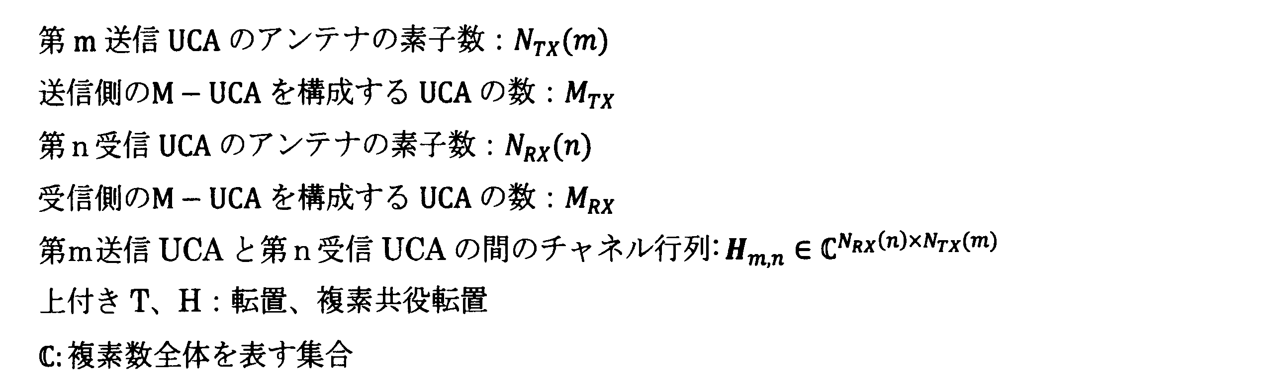
図1において、M(Multi)-UCAは、複数のUCAを同心円状かつ等間隔に配置した構成である。ここでは、4つのUCAを配置した構成を示し、内側のUCAから順番に、第1UCA,第2UCA,第3UCA,第4UCAとする。なお、送信UCAの場合は第n送信UCAと呼び、受信UCAの場合は第n受信UCAと呼ぶ。各UCAは8素子のアンテナ素子(図中、●で示す)を備える例を示すが、各UCAのアンテナ素子数は必ずしも同数である必要はない。FIG. 1 shows a configuration example of the M-UCA of the OAM multiplex communication system of the present invention.
In FIG. 1, M (Multi) -UCA has a configuration in which a plurality of UCAs are arranged concentrically and at equal intervals. Here, a configuration in which four UCAs are arranged is shown, and the first UCA, the second UCA, the third UCA, and the fourth UCA are used in order from the inner UCA. In the case of transmission UCA, it is called the nth transmission UCA, and in the case of reception UCA, it is called the nth reception UCA. An example is shown in which each UCA includes eight antenna elements (indicated by ● in the figure), but the number of antenna elements of each UCA does not necessarily have to be the same.
以下の説明に用いる各記号の定義は次の通りである。
(実施例1)
図2は、本発明のOAM多重通信システムの実施例1の構成を示す。
図2において、送信局は、S/P変換・信号処理部11、L個の第1送信ウエイト乗算部13-1~第L送信ウエイト乗算部13-L、MTX個の送信UCA15-1~15-MTXにそれぞれ対応するMTX個の第1送信OAMモード生成処理部14-1~第MTX送信OAMモード生成処理部14-MTX、参照信号送信部16により構成される。(Example 1)
FIG. 2 shows the configuration of the first embodiment of the OAM multiplex communication system of the present invention.
In FIG. 2, the transmitting station has S / P conversion /
受信局は、MRX個の受信UCA21-1~21-MRXにそれぞれ対応するMRX個の第1受信OAMモード分離処理部22-1~第MRX受信OAMモード分離処理部22-MRX、L個の第1受信ウエイト乗算部23-1~第L受信ウエイト乗算部23-L、信号処理・P/S変換部24、チャネル状態取得部26、ウエイト演算部27、フィードバック部28により構成される。The receiving station has M RX first reception OAM mode separation processing units 22-1 to M RX reception OAM mode separation processing units 22-M RX corresponding to M RX reception UCA21-1 to 21-M RX , respectively. , L first reception weight multiplication unit 23-1 to L reception weight multiplication unit 23-L, signal processing / P /
実施例1のOAM多重通信システムは、従来構成と異なり、M-UCAを用いたアンテナ構成となる。また、チャネル情報を取得して演算したウエイトを送信局にフィードバックする点、および、送信局および受信局でチャネル情報に基づき演算したウエイトを乗算する点で異なる。 The OAM multiplex communication system of the first embodiment has an antenna configuration using M-UCA, unlike the conventional configuration. Further, it differs in that the weight calculated based on the channel information is fed back to the transmitting station and the weight calculated based on the channel information is multiplied by the transmitting station and the receiving station.
はじめに、実施例1の送信局および受信局の入出力関係を数式表現する。送信局は、入力した送信信号系列をS/P変換してL個の並列なビット列に変換し、各ビット列を変調して送信信号sl (l=1,2,…,L)を生成する。第l送信ウエイト乗算部13-lは、送信信号sl に対して送信ウエイトVl を乗算し、s'lを出力する。

第m送信OAMモード生成処理部14-mは、第1送信ウエイト乗算部13-1~第L送信ウエイト乗算部13-Lの出力の第m番目の信号s'l[m],(l=1,2,…,L) を並べた信号ベクトル
S'[m]=(s'1[m],…,s'L[m])T
を入力し、S'[m] に対してDFT行列Dm
TX を乗算して出力する。ここで、Dm
TX は、その第p行q列成分が
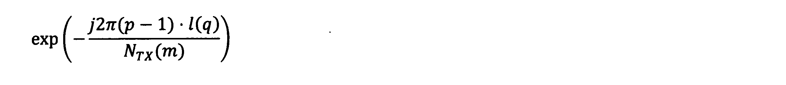
Is input, and S'[m] is multiplied by the DFT matrix D m TX and output. Here, D m TX has its p-row and q-column components.
なお、DFT演算に係る処理は、非特許文献1と同一のバトラーマトリクスを用いたアナログ回路で実施してもよく、ディジタル信号処理で実施してもよい。
第1送信OAMモード生成処理部14-1~第MTX送信OAMモード生成処理部14-MTXの出力信号は、各DFT演算部と接続する送信UCA15-1~15-MTXから受信UCAに向けて送信される。このとき、第k受信UCA21-kで受信される信号は以下の通りである。

The output signal of the first transmission OAM mode generation processing unit 14-1 to M TX transmission OAM mode generation processing unit 14-M TX is transmitted from the transmission UCA15-1 to 15-M TX connected to each DFT calculation unit to the reception UCA. Will be sent to. At this time, the signal received by the kth reception UCA21-k is as follows.
次に、受信局の第k受信OAMモード分離処理部22-kは、第k受信UCA21-kで受信した信号に対してIDFT行列Dk
RX を乗算して出力する。ここで、IDFT行列Dk
RX のp行q列成分は次のように表される。

第l受信ウエイト乗算部23-lは、第1受信OAMモード分離処理部22-1~第MRX受信OAMモード分離処理部22-MRXの第l番目の出力rk[l],(k=1,2,…,MRX) を並べたベクトルr[l]

信号処理・P/S変換部24は、受信ウエイト乗算後の信号rl から送信された情報ビット列を推定し、P/S変換後、もとの情報ビット列の順番に整列させる。The signal processing / P /
また、送信局の参照信号送信部16は、チャネル応答を推定するための既知信号系列を受信局に向けて送信する。
Further, the reference
受信局のチャネル状態取得部26は、第1受信OAMモード分離処理部22-1~第MRX受信OAMモード分離処理部22-MRXと接続され、既知信号系列に基づきチャネル応答を推定する。推定した情報をウエイト演算部27に出力する。The channel
ウエイト演算部27は、チャネル状態取得部26の推定値に基づき送信ウエイトおよび受信ウエイトを決定し、受信局の第1受信ウエイト乗算部23-1~第L受信ウエイト乗算部23-Lに設定し、フィードバック部28を介して、送信局の第1送信ウエイト乗算部13-1~第L送信ウエイト乗算部13-Lに設定する。
The
次に、ウエイト演算部27における送信ウエイトと受信ウエイトの演算方法を説明する。説明を明確化するために、受信ウエイト乗算後の信号rl に残留する干渉成分を数式表現する。初めに、送信局と受信局のM-UCA同士が正面で対向しており、干渉が生じない場合、チャネル行列Hm,k は、左からIDFT行列Dk
RX、右側からDFT行列Dm
TXを乗算することによって対角化される。したがって、第l受信ウエイト乗算部23-lから出力される信号rl は、以下のようになる。

式(4) 中のΛl は各チャネルの応答を表すMRX×MTXの行列である。式(4) より正面対向時は、インデックスlが異なる信号(異なるOAMモード)からの干渉が生じないことが分かる。したがって、従来構成と同様に、信号処理・P/S変換部24は信号rl ごとにビット列sl を他モードからの干渉なく推定できる。一方、それ以外の場合、rl は、他モードからの干渉を含んだ信号となる。Λ l in Eq. (4) is a matrix of M RX × M TX representing the response of each channel. From Eq. (4), it can be seen that interference from signals having different indexes l (different OAM modes) does not occur when facing the front. Therefore, as in the conventional configuration, the signal processing / P /

干渉成分(式(5) の第2項の信号成分)を抑圧し、通信品質を改善するための送信ウエイトVl と受信ウエイトUl の決定方法について以下に説明する。The method of determining the transmission weight V l and the reception weight U l for suppressing the interference component (the signal component of the second term of the equation (5)) and improving the communication quality will be described below.
実施例1では、干渉成分の行列を特異値分解(Singular Value Decomposition:SVD)し、干渉量の多い左特異ベクトルと直交するベクトルを受信ウエイトに採用することで干渉成分を抑圧する。 In the first embodiment, the interference component is suppressed by performing a singular value decomposition (SVD) of the matrix of the interference components and adopting a vector orthogonal to the left singular vector having a large amount of interference as the receiving weight.
はじめに、干渉量が多い特異ベクトルを見つけるために、干渉成分の行列Λl
(INT)を特異値分解すると式(6) のようになる。


式(5) の受信信号は、式(6) の特異値分解結果を用いて次のように書き直すことができる。

式(7) より、受信信号rl に対して左特異ベクトルul,m の複素共役転置uH l,mを乗算すれば、左特異ベクトル同士の直交性から第l受信ウエイト乗算部23-lの出力に含まれる干渉成分(式(7) の第2項)のうちσmul,mvH l,m以外の成分を除去できることがわかる。受信信号の干渉を効果的に抑圧するには、特異値が最小の左特異ベクトルuH l,MRXを受信ウエイトUl に採用し、干渉の大きい項を除去すればよい。このとき受信信号rl は以下のようになり、受信ウエイト乗算後に干渉成分が抑圧されたことが分かる。なお、受信ウエイトは最小特異値の左特異ベクトルuH l,MRX以外の例えば、uH l,MRX-1であってもよい。 Equation (7) From the received signal rl Left singular vector ul, mComplex conjugate transpose uH l, mBy multiplying by, σ of the interference components (the second term of Eq. (7)) included in the output of the first received weight multiplying unit 23-l due to the orthogonality between the left singular vectors.mul, mvH l, mIt can be seen that components other than the above can be removed. To effectively suppress the interference of the received signal, the left singular vector u with the smallest singular valueH l, MRXReceive weight Ul It may be adopted in the above and the term with large interference may be removed. At this time, the received signal rl Is as follows, and it can be seen that the interference component was suppressed after the reception weight multiplication. The reception weight is the left singular vector u with the minimum singular value.H l, MRXOther than, for example, uH l, MRX-1May be.

一方、行列uH l,MRXΛl は、受信信号に干渉の主成分を含まない固有空間を形成する。この固有空間のうち、非ゼロの固有値の固有ベクトルを送信ウエイトとして信号を送信すれば、干渉の主成分を含まない信号伝送が実現できる。具体的には、送信ウエイトVl を、行列uH l,MRXΛl を特異値分解することで得られる右特異ベクトルのうち、非ゼロ特異値の右特異ベクトルに決定する。On the other hand, the matrix u H l and MRX Λ l form an eigenspace in which the received signal does not contain the main component of interference. If a signal is transmitted using an eigenvector of a non-zero eigenvalue in this eigenspace as a transmission weight, signal transmission that does not include the main component of interference can be realized. Specifically, the transmission weight V l is determined to be a non-zero singular value right singular vector among the right singular vectors obtained by singular value decomposition of the matrices u H l and MRX Λ l .
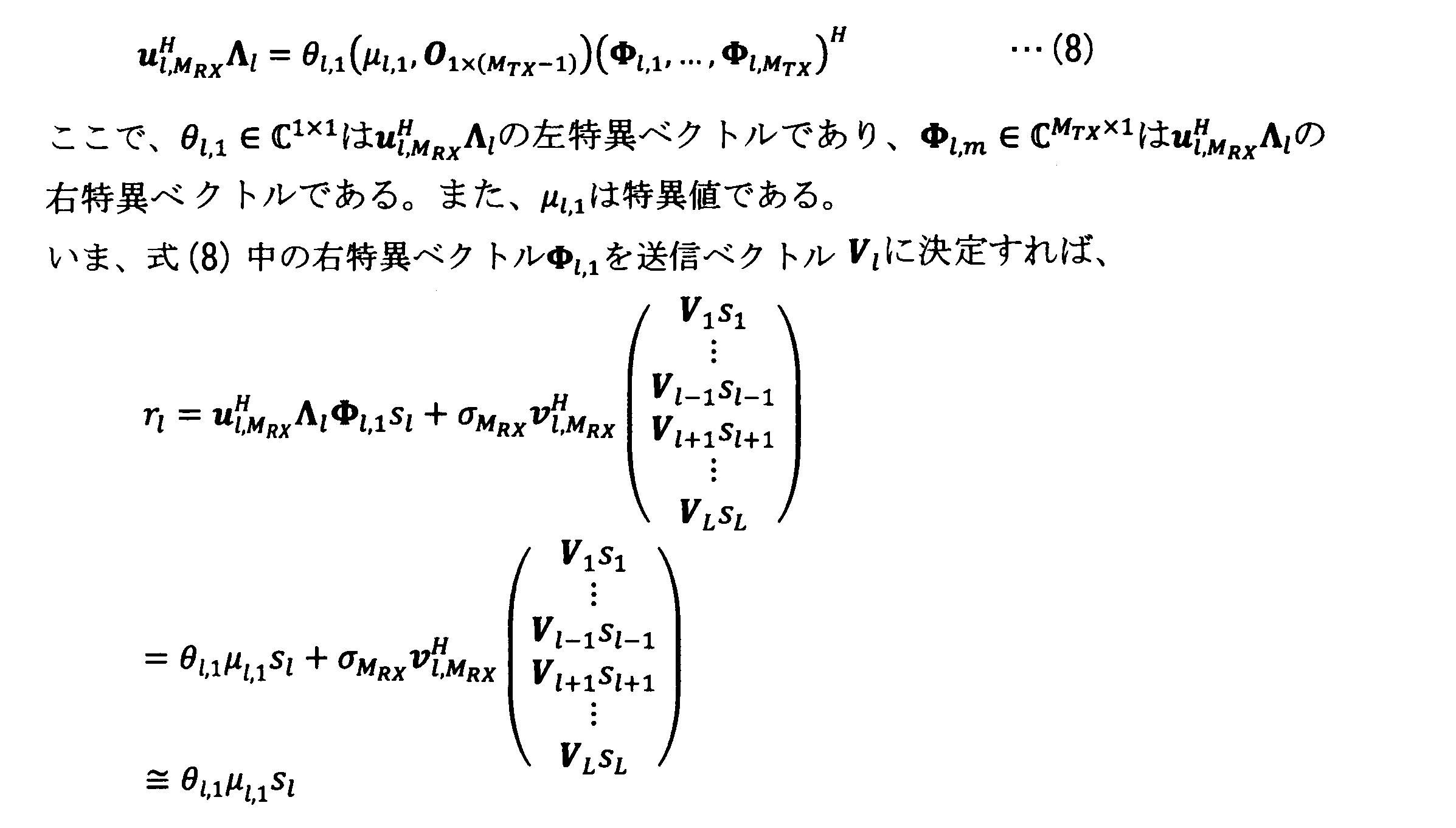
図3は、本発明のOAM多重通信システムの実施例1の処理手順を示す。
図3において、送信局に送信信号系列が入力すると、S/P変換・信号処理部11は変調信号を生成する(S11) 。次に、送信局の参照信号送信部16から既知信号系列を送信する(S12) 。受信局は、既知信号系列を受信すると、チャネル状態取得部26が既知信号系列に基づき、各チャネルの応答Λl およびΛl,k を推定する(S21)。ウエイト演算部27は、推定したチャネルの応答Λl およびΛl,k に基づき、式(5) および式(8) の特異値分解を実施し、送信ウエイトVl と受信ウエイトUl を決定し(S22)、受信ウエイトUl を受信局の各受信ウエイト乗算部23に設定する。さらに、フィードバック部28は、ウエイト演算部27で決定した送信ウエイトVl を送信局の各送信ウエイト乗算部13に設定する(S23)。
FIG. 3 shows a processing procedure of the first embodiment of the OAM multiplex communication system of the present invention.
In FIG. 3, when the transmission signal sequence is input to the transmission station, the S / P conversion /
次に、送信局の各送信ウエイト乗算部13は、ステップS11で生成した変調信号に対して送信ウエイトVl を乗算する(S13)。さらに、送信OAMモード生成処理部14は、送信ウエイトVl を乗算した変調信号に対してDFT演算によりOAMモード生成処理を行い(S14)、各OAMモードの信号が送信局の各送信UCA15から送信される(S15)。Next, each transmission
受信局の各受信UCA21は、送信局から送信された信号を受信し(S24)、受信OAMモード分離処理部22でIDFT演算によりOAMモード分離処理を行う(S25)。次に、各受信ウエイト乗算部23は、各OAMモードの受信信号に対して受信ウエイトUl を乗算する(S26)。信号処理・P/S変換部24は、以上の処理によりモード間干渉が抑圧された受信信号を復調してビット列に変換し、さらにP/S変換して元の情報ビット列の並びに整列させて出力する(S27)。Each receiving
(実施例1の変形)
図4は、本発明のOAM多重通信システムの実施例1の変形構成を示す。
図4において、送信局は、S/P変換・信号処理部11、L個の第1送信ウエイト乗算部13-1~第L送信ウエイト乗算部13-L、MTX個の送信UCA15-1~15-MTXにそれぞれ対応するMTX個の第1送信OAMモード生成処理部14-1~第MTX送信OAMモード生成処理部14-MTX、ウエイト演算部17により構成される。(Modification of Example 1)
FIG. 4 shows a modified configuration of the first embodiment of the OAM multiplex communication system of the present invention.
In FIG. 4, the transmitting station has S / P conversion /
受信局は、MRX個の受信UCA21-1~21-MRXにそれぞれ対応するMRX個の第1受信OAMモード分離処理部22-1~第MRX受信OAMモード分離処理部22-MRX、L個の第1受信ウエイト乗算部23-1~第L受信ウエイト乗算部23-L、信号処理・P/S変換部24、ウエイト演算部29により構成される。The receiving station has M RX first reception OAM mode separation processing units 22-1 to M RX reception OAM mode separation processing units 22-M RX corresponding to M RX reception UCA21-1 to 21-M RX , respectively. , L first reception weight multiplication unit 23-1 to L reception weight multiplication unit 23-L, signal processing / P /
図2に示す実施例1との違いは、受信局でチャネル推定を実施しない点と、送信局と受信局とが独立に送信ウエイトおよび受信ウエイトを決定する点にある。すなわち、図4の構成では、送信局および受信局においてあらかじめチャネル応答が推定されており、推定値は送信局のウエイト演算部17および受信局のウエイト演算部29が保持しており、ウエイト演算部17,29がチャネル応答に基づいて送信ウエイトと受信ウエイトを決定し、送信ウエイト乗算部13および受信ウエイト乗算部23に設定する。
The difference from the first embodiment shown in FIG. 2 is that the receiving station does not perform channel estimation, and the transmitting station and the receiving station independently determine the transmitting weight and the receiving weight. That is, in the configuration of FIG. 4, the channel response is estimated in advance at the transmitting station and the receiving station, and the estimated value is held by the
図5は、本発明のOAM多重通信システムの実施例1の変形構成の処理手順を示す。
図5において、送信局に送信信号系列が入力すると、ウエイト演算部17が事前に保持しているチャネル応答値に基づいて送信ウエイトVl を決定し、各送信ウエイト乗算部13に設定する(S31)。S/P変換・信号処理部11は、変調信号を生成する(S32) 。次に、各送信ウエイト乗算部13は、生成した変調信号に対して送信ウエイトVl を乗算する(S33)。さらに、送信OAMモード生成処理部14は、送信ウエイトVl を乗算した変調信号に対してDFT演算によりOAMモード生成処理を行い(S34)、各OAMモードの信号が各送信UCA15から送信される(S35)。
FIG. 5 shows a processing procedure of a modified configuration of the first embodiment of the OAM multiplex communication system of the present invention.
In FIG. 5, when the transmission signal sequence is input to the transmission station, the transmission weight V is based on the channel response value previously held by the weight calculation unit 17.lIs determined and set in each transmission weight multiplication unit 13 (S31). The S / P conversion /
一方、受信局は、ウエイト演算部29が事前に保持しているチャネル応答値に基づいて受信ウエイトUl を決定し、各受信ウエイト乗算部23に設定する(S41)。各受信UCA21は、送信局から送信された信号を受信し(S42)、受信OAMモード分離処理部22でIDFT演算によりOAMモード分離処理を行う(S43)。次に、各受信ウエイト乗算部23は、各OAMモードの受信信号に対して受信ウエイトUl を乗算する(S44)。信号処理・P/S変換部24は、以上の処理によりモード間干渉が抑圧された受信信号を復調してビット列に変換し、さらにP/S変換して元の情報ビット列の並びに整列させて出力する(S45)。On the other hand, the receiving station determines the receiving weight Ul based on the channel response value held in advance by the
(実施例2)
図6は、本発明のOAM多重通信システムの実施例2の構成を示す。
図6において、送信局は、S/P変換・信号処理部12、それぞれM1 ~ML の信号を入力するL個の第1送信ウエイト乗算部13-1~第L送信ウエイト乗算部13-L、MTX個の送信UCA15-1~15-MTXにそれぞれ対応するMTX個の第1送信OAMモード生成処理部14-1~第MTX送信OAMモード生成処理部14-MTX、参照信号送信部16により構成される。(Example 2)
FIG. 6 shows the configuration of the second embodiment of the OAM multiplex communication system of the present invention.
In FIG. 6, the transmitting station is an S / P conversion /
受信局は、MRX個の受信UCA21-1~21-MRXにそれぞれ対応するMRX個の第1受信OAMモード分離処理部22-1~第MRX受信OAMモード分離処理部22-MRX、L個の第1受信ウエイト乗算部23-1~第L受信ウエイト乗算部23-L、それぞれM1 ~ML の受信信号を入力する信号処理・P/S変換部25、チャネル状態取得部26、ウエイト演算部27、フィードバック部28により構成される。The receiving station has M RX first reception OAM mode separation processing units 22-1 to M RX reception OAM mode separation processing units 22-M RX corresponding to M RX reception UCA21-1 to 21-M RX , respectively. , L first reception weight multiplication unit 23-1 to L reception weight multiplication unit 23-L, signal processing / P /
実施例2のOAM多重通信システムと実施例1との違いは、1つの送信ウエイト乗算部13へ入力する変調信号が複数系統存在し、1つの受信ウエイト乗算部23から出力される受信信号が複数系統存在する。また、入力の系統数が増えたことに伴い、送信ウエイトと受信ウエイトの行列サイズも異なり、送信ウエイト乗算部13および受信ウエイト乗算部23の処理方法が異なる。これにより、OAMモードのうち、SINR (Signal-to-interference-plus-noise ratio)が高いOAMモードを選択して使用することで、チルトや軸ずれ、マルチパスの干渉を補償しつつ、スループットを向上させる点が実施例1と異なる。
The difference between the OAM multiplex communication system of the second embodiment and the first embodiment is that there are a plurality of modulation signals input to one transmission
第l送信ウエイト乗算部13-lは、Ml 個の並列な変調信号sl を入力し、各変調信号に対して送信ウエイトVl を乗算した変調信号s'lを出力する。

第l受信ウエイト乗算部23-lは、第1受信OAMモード分離処理部22-1~第MRX受信OAMモード分離処理部22-MRXの出力(rl[l],…,rMRX[l])Tを入力し、受信ウエイトUlを乗算した受信信号rl を出力する 。

送信アンテナと受信アンテナが理想的な見通し環境、かつ、正面対向配置でない場合、受信信号ベクトルr l は、

以下、実施例2における送信ウエイトVl と受信ウエイトUl の決定方法について説明する。(9) の受信信号は、式(6) の特異値分解結果を用いて次のように書き直すことができる。Hereinafter, a method for determining the transmission weight V l and the reception weight U l in the second embodiment will be described. The received signal in (9) can be rewritten as follows using the singular value decomposition result in Eq. (6).


すなわち、(uH l,MRX-(Ml-1),…,uH l,MRX-1,uH l,MRX)を乗算することで、干渉成分の主要な成分を含むベクトル空間を除去することができる。続いて、主信号成分の行列(uH l,MRX-(Ml-1),…,uH l,MRX-1,uH l,MRX)Λl を特異値分解して得られる特異ベクトルを用いて、送信ウエイトと受信ウエイトを決定する。これにより、モード間の干渉を低減しつつ固有モード伝送できるようになる。同行列の特異値分解結果は、次の通りである。That is, by multiplying by (u H l, MRX- (Ml-1) , ..., u H l, MRX-1 , u H l, MRX ), the vector space containing the main components of the interfering components is removed. be able to. Next, the singular vector obtained by decomposing the matrix of the main signal components (u H l, MRX- (Ml-1) , ..., u H l, MRX-1 , u H l, MRX ) Λ l into singular values is obtained. It is used to determine the transmission weight and the reception weight. This enables transmission in the unique mode while reducing interference between modes. The results of singular value decomposition of the same matrix are as follows.

ここで、Θl (img),Θl (ker)はそれぞれ、(uH l,MRX-(Ml-1),…,uH l,MRX-1,uH l,MRX)Λlの非ゼロ特異値に対応する左特異ベクトル、ゼロ特異値に対応する左特異ベクトルであり、Φl (img),Φl (ker)はそれぞれ、同行列の非ゼロ特異値に対応する右特異ベクトル、ゼロ特異値に対応する右特異ベクトルである。式(10)の特異値分解結果に基づき、送信ウエイトVl および受信ウエイトUl を以下の式(11)のように決定する。Here, Θ l (img) and Θ l (ker) are non- (u H l, MRX- (Ml-1) , ..., u H l, MRX-1 , u H l, MRX ) Λ l , respectively. The left singular vector corresponding to the zero singular value and the left singular vector corresponding to the zero singular value, and Φ l (img) and Φ l (ker) are the right singular vector corresponding to the non-zero singular value of the same matrix, respectively. It is a right singular vector corresponding to a zero singular value. Based on the singular value decomposition result of Eq. (10), the transmission weight V l and the reception weight U l are determined as shown in Eq. (11) below.


多重数Ml は、SINRなどから計算される合計容量に従う選択規範でもよく、別の選択規範に則って決めてもよい。あるいは、多重数Ml は事前にシステムが固定的に決めているものでもよい。The multiple number M l may be a selection norm according to the total capacity calculated from SINR or the like, or may be determined according to another selection norm. Alternatively, the multiply perfect number M l may be fixedly determined by the system in advance.
図7は、本発明のOAM多重通信システムの実施例2の処理手順を示す。
図7において、送信局は、参照信号送信部16から既知信号系列を送信する(S51) 。受信局は、既知信号系列を受信すると、チャネル状態取得部26が既知信号系列に基づき、各チャネルの応答Λl およびΛl,k を推定する(S61)。次に、ウエイト演算部27は、推定したチャネルの応答Λl およびΛl,k に基づき、式(9) の特異値分解を実施し、送信ウエイトVl と受信ウエイトUl を式(10)のように決定するとともに多重数Ml を決定し、受信ウエイトUl を各受信ウエイト乗算部23に設定する(S62)。多重数Ml は、あらかじめ決められているものでもよく、適応的に選択するものでもよい。フィードバック部28は、ウエイト演算部27で決定した多重数Ml を送信局のS/P変換・信号処理部12に設定するとともに、送信ウエイトVl を送信局の各送信ウエイト乗算部13に設定する(S63)。FIG. 7 shows the processing procedure of the second embodiment of the OAM multiplex communication system of the present invention.
In FIG. 7, the transmitting station transmits a known signal sequence from the reference signal transmitting unit 16 (S51). When the receiving station receives the known signal sequence, the channel
送信局は、多重数Ml が設定されたS/P変換・信号処理部12において変調信号を生成する(S52) 。次に、各送信ウエイト乗算部13は、生成された変調信号に対して送信ウエイトVl を乗算する(S53)。さらに、送信OAMモード生成処理部14は、送信ウエイトVl を乗算した変調信号に対してDFT演算によりOAMモード生成処理を行い(S54)、各OAMモードの信号が送信局の各送信UCA15から送信される(S55)。
The transmitting station is a multiply perfect number MlGenerates a modulated signal in the S / P conversion /
受信局の各受信UCA21は、送信局から送信された信号を受信し(S64)、受信OAMモード分離処理部22でIDFT演算によりOAMモード分離処理を行う(S65)。次に、各受信ウエイト乗算部23は、各OAMモードの受信信号に対して受信ウエイトUl を乗算する(S66)。信号処理・P/S変換部25は、以上の処理によりモード間干渉が抑圧された受信信号を復調してビット列に変換し、さらにP/S変換して元の情報ビット列の並びに整列させて出力する(S67)。Each receiving
(実施例2の変形)
図8は、本発明のOAM多重通信システムの実施例2の変形構成を示す。
図8において、送信局は、S/P変換・信号処理部12、L個の第1送信ウエイト乗算部13-1~第L送信ウエイト乗算部13-L、MTX個の送信UCA15-1~15-MTXにそれぞれ対応するMTX個の第1送信OAMモード生成処理部14-1~第MTX送信OAMモード生成処理部14-MTX、ウエイト演算部17により構成される。(Modification of Example 2)
FIG. 8 shows a modified configuration of the second embodiment of the OAM multiplex communication system of the present invention.
In FIG. 8, the transmitting station has S / P conversion /
受信局は、MRX個の受信UCA21-1~21-MRXにそれぞれ対応するMRX個の第1受信OAMモード分離処理部22-1~第MRX受信OAMモード分離処理部22-MRX、L個の第1受信ウエイト乗算部23-1~第L受信ウエイト乗算部23-L、それぞれM1 ~ML の受信信号を入力する信号処理・P/S変換部25、ウエイト演算部29により構成される。The receiving station has M RX first reception OAM mode separation processing units 22-1 to M RX reception OAM mode separation processing units 22-M RX corresponding to M RX reception UCA21-1 to 21-M RX , respectively. , L first reception weight multiplication unit 23-1 to L reception weight multiplication unit 23-L, signal processing / P /
図6に示す実施例2との違いは、受信局でチャネル推定を実施しない点と、送信局と受信局とが独立に送信ウエイトおよび受信ウエイトを決定する点にある。すなわち、図8の構成では、送信局および受信局においてあらかじめチャネル応答が推定されており、推定値は送信局のウエイト演算部17および受信局のウエイト演算部29が保持しており、ウエイト演算部17,29がチャネル応答に基づいて送信ウエイトと受信ウエイトを決定し、送信ウエイト乗算部13および受信ウエイト乗算部23に設定する。また、事前に多重数Ml が決められており、送信局と受信局はともに多重数Ml の情報を有するため、フィードバック処理を介さず通信ができる。The difference from the second embodiment shown in FIG. 6 is that the receiving station does not perform channel estimation, and the transmitting station and the receiving station independently determine the transmitting weight and the receiving weight. That is, in the configuration of FIG. 8, the channel response is estimated in advance at the transmitting station and the receiving station, and the estimated value is held by the
本発明のOAM多重通信システムの実施例2の変形構成における処理手順は、図5に示す実施例1の変形構成における処理手順に対して、送信局のS/P変換・信号処理部12において多重数Ml に応じた変調信号を生成し、受信局で信号処理・P/S変換部25において多重数Ml に応じた受信信号を復調する以外は同様である。The processing procedure in the modified configuration of the second embodiment of the OAM multiplex communication system of the present invention is multiplexed in the S / P conversion /
11,12 S/P変換・信号処理部
13 送信ウエイト乗算部
14 送信OAMモード生成処理部
15 送信UCA
16 参照信号送信部
17 ウエイト演算部
21 受信UCA
22 受信OAMモード分離処理部
23 受信ウエイト乗算部
24,25 信号処理・P/S変換部
26 チャネル状態取得部
27 ウエイト演算部
28 フィードバック部
29 ウエイト演算部11,12 S / P conversion /
16 Reference
22 Reception OAM mode
Claims (8)
前記送信局と同様に複数MRX個のUCAからなるM-UCAを用いた受信アンテナを含む受信局と
を備え、電磁波の軌道角運動量(以下、OAM)モードを用いて複数の送信信号系列を空間多重伝送するOAM多重通信システムであって、
前記送信局は、
前記複数の送信信号系列を送信する前記OAMモードごとに入力し、前記OAMモードごとの送信信号系列にそれぞれ送信ウエイトを乗算し、前記M-UCAを構成するUCAに対応するMTX個の信号に変換して出力する前記OAMモードごとの複数の送信ウエイト乗算部と、
前記複数の送信ウエイト乗算部がそれぞれ出力する前記UCA対応の信号を入力して離散フーリエ変換を行い、それぞれ対応する前記UCAに出力するMTX個の送信OAMモード生成処理部と
を備え、
前記受信局は、
前記M-UCAを構成するUCAからそれぞれ信号を入力して逆フーリエ変換を行い、受信信号系列ごとに出力するMRX個の受信OAMモード分離処理部と、
前記受信OAMモード分離処理部が出力する前記OAMモードごとの受信信号系列にそれぞれ受信ウエイトを乗算し、空間多重伝送された受信信号系列を分離するとともに、空間多重されたOAMモード間の干渉を抑圧して出力する前記OAMモードごとの複数の受信ウエイト乗算部と
を備えたことを特徴とするOAM多重通信システム。 Transmission using an M-UCA consisting of a plurality of MTX UCAs having different diameters arranged concentrically and at equal intervals of an evenly spaced circular array antenna (hereinafter referred to as UCA) in which a plurality of antenna elements are arranged in a circle at equal intervals. The transmitting station including the antenna and
Similar to the transmitting station, it is equipped with a receiving station including a receiving antenna using M-UCA consisting of a plurality of M RX UCA, and a plurality of transmission signal sequences are provided using the orbital angular momentum (hereinafter referred to as OAM) mode of electromagnetic waves. It is an OAM multiplex communication system that performs spatial multiplex transmission.
The transmitting station
The plurality of transmission signal sequences are input for each OAM mode to be transmitted , the transmission signal sequence for each OAM mode is multiplied by a transmission weight, and the M TX signals corresponding to the UCA constituting the M-UCA are obtained. A plurality of transmission weight multiplication units for each OAM mode to be converted and output, and
It is provided with MTX transmission OAM mode generation processing units that input the UCA-compatible signals output by the plurality of transmission weight multiplication units to perform discrete Fourier transform and output to the corresponding UCAs .
The receiving station
MRX receive OAM mode separation processing units that input signals from each of the UCAs constituting the M-UCA, perform inverse Fourier transform, and output each received signal sequence.
The reception weight is multiplied by the received signal sequence for each OAM mode output by the received OAM mode separation processing unit to separate the received signal sequence transmitted spatially multiplexed, and the interference between the spatially multiplexed OAM modes is suppressed. The OAM multiplex communication system is provided with a plurality of reception weight multiplying units for each OAM mode to output.
前記送信局から前記受信局に送信された既知信号系列に対する前記受信OAMモード分離処理部の出力値からチャネル推定を行い、前記送信ウエイトと前記受信ウエイトを決定するウエイト演算部を備え、
前記受信ウエイトは前記受信ウエイト乗算部に設定し、前記送信ウエイトは前記受信局から前記送信局へフィードバックされて前記送信ウエイト乗算部に設定し、空間多重伝送されたOAMモード間の干渉成分を抑圧する構成である
ことを特徴とするOAM多重通信システム。 In the OAM multiplex communication system according to claim 1 ,
A weight calculation unit that estimates a channel from the output value of the reception OAM mode separation processing unit for a known signal sequence transmitted from the transmission station to the reception station and determines the transmission weight and the reception weight is provided.
The reception weight is set in the reception weight multiplication unit, the transmission weight is fed back from the reception station to the transmission station and set in the transmission weight multiplication unit, and the interference component between the OAM modes transmitted by spatial multiplexing is suppressed. An OAM multiplex communication system characterized in that it is configured to perform.
前記送信局は、
前記OAMモードごとの複数の送信ウエイト乗算部で、前記複数の送信信号系列を送信する前記OAMモードごと入力し、前記OAMモードごとの送信信号系列にそれぞれ送信ウエイトを乗算し、前記M-UCAを構成するUCAに対応するMTX個の信号に変換して出力し、
MTX個の送信OAMモード生成処理部で、前記複数の送信ウエイト乗算部がそれぞれ出力する前記UCA対応の信号を入力して離散フーリエ変換を行い、それぞれ対応する前記UCAに出力し、
前記受信局は、
MRX個の受信OAMモード分離処理部で、前記M-UCAを構成するUCAからそれぞれ信号を入力して逆フーリエ変換を行い、受信信号系列ごとに出力し、
前記OAMモードごとの複数の受信ウエイト乗算部で、前記受信OAMモード分離処理部が出力する前記OAMモードごとの受信信号系列にそれぞれ受信ウエイトを乗算し、空間多重伝送された受信信号系列を分離するとともに、空間多重されたOAMモード間の干渉を抑圧して出力する
ことを特徴とするOAM多重通信システムのモード間干渉除去方法。 Transmission using an M-UCA consisting of a plurality of MTX UCAs having different diameters arranged concentrically and at equal intervals by equidistant circular array antennas (hereinafter referred to as UCA) in which a plurality of antenna elements are arranged in a circle at equal intervals. It is equipped with a transmitting station including an antenna and a receiving station including a receiving antenna using an M-UCA composed of a plurality of MRX UCAs like the transmitting station, and uses an electromagnetic wave orbital angular momentum (hereinafter, OAM) mode. This is a mode-to-mode interference elimination method for an OAM multiplex communication system that spatially multiplexes a plurality of transmission signal sequences.
The transmitting station
In the plurality of transmission weight multiplication units for each OAM mode, the plurality of transmission signal sequences are input for each OAM mode to be transmitted, the transmission signal series for each OAM mode is multiplied by the transmission weight, and the M-UCA is obtained. Converts to MTX signals corresponding to the constituent UCA and outputs them.
In the MTX transmission OAM mode generation processing unit, the UCA-compatible signals output by the plurality of transmission weight multiplication units are input to perform a discrete Fourier transform, and the signals are output to the corresponding UCAs .
The receiving station
In the receive OAM mode separation processing unit of M RX pieces, signals are input from each of the UCAs constituting the M-UCA, inverse Fourier transform is performed, and the signals are output for each received signal sequence.
The plurality of reception weight multiplication units for each OAM mode multiply the reception signal sequence for each OAM mode output by the reception OAM mode separation processing unit by the reception weight, and separate the spatially multiplexed received signal series. At the same time, a method for eliminating intermode interference of an OAM multiplex communication system, which is characterized in that interference between spatially multiplexed OAM modes is suppressed and output.
前記送信局から前記受信局に送信された既知信号系列に対する前記受信OAMモード分離処理部の出力値からチャネル推定を行い、前記送信ウエイトと前記受信ウエイトを決定し、
前記受信ウエイトは前記受信ウエイト乗算部に設定し、前記送信ウエイトは前記受信局から前記送信局へフィードバックされて前記送信ウエイト乗算部に設定し、空間多重されたOAMモード間の干渉を抑圧する
ことを特徴とするOAM多重通信システムのモード間干渉除去方法。 In the intermode interference elimination method of the OAM multiplex communication system according to claim 3 .
Channel estimation is performed from the output value of the reception OAM mode separation processing unit for the known signal sequence transmitted from the transmission station to the reception station, and the transmission weight and the reception weight are determined.
The reception weight is set in the reception weight multiplication unit, and the transmission weight is fed back from the reception station to the transmission station and set in the transmission weight multiplication unit to suppress interference between spatially multiplexed OAM modes. A method for removing interference between modes of an OAM multiplex communication system.
前記受信OAMモード分離処理部の出力のうち、特定の離散周波数成分に残留する他離散周波数成分からの干渉成分を表す行列の特異値分解の結果と、自離散周波数成分を表す行列の特異値分解の結果とに基づき、空間多重化された信号同士の干渉を抑圧するための前記送信ウエイトおよび前記受信ウエイトを決定する
ことを特徴とするOAM多重通信システムのモード間干渉除去方法。 In the intermode interference elimination method of the OAM multiplex communication system according to claim 4 .
Of the output of the received OAM mode separation processing unit, the result of the singular value decomposition of the matrix representing the interference component from the other discrete frequency component remaining in the specific discrete frequency component and the singular value decomposition of the matrix representing the self-discrete frequency component. A method for eliminating intermode interference of an OAM multiplex communication system, which comprises determining the transmission weight and the reception weight for suppressing interference between spatially multiplexed signals based on the results of the above.
前記受信OAMモード分離処理部の出力に生じる他離散周波数成分からの干渉成分を表す行列の特異値分解の結果のうち、左特異ベクトルに属するベクトルのうちの一つ以上のベクトルと直交するベクトルを含むウエイトを前記受信ウエイトとする
ことを特徴とするOAM多重通信システムのモード間干渉除去方法。 In the intermode interference elimination method of the OAM multiplex communication system according to claim 4 .
Among the results of singular value decomposition of a matrix representing interference components from other discrete frequency components generated in the output of the reception OAM mode separation processing unit, a vector orthogonal to one or more of the vectors belonging to the left singular vector is obtained. A method for removing interference between modes of an OAM multiplex communication system, wherein the weight including the weight is the reception weight.
前記受信OAMモード分離処理部の出力に生じる他離散周波数成分からの干渉成分を表す行列の特異値分解の結果のうち、左特異ベクトルに属するベクトルと直交するベクトルと、自離散周波数成分を表す行列との乗算結果の特異値分解を基に、前記送信ウエイトおよび前記受信ウエイトを決定する
ことを特徴とするOAM多重通信システムのモード間干渉除去方法。 In the intermode interference elimination method of the OAM multiplex communication system according to claim 4 .
Among the results of singular value decomposition of the matrix representing the interference component from other discrete frequency components generated in the output of the received OAM mode separation processing unit, the vector orthogonal to the vector belonging to the left singular vector and the matrix representing the self-discrete frequency component. A method for removing intermode interference of an OAM multiplex communication system, which comprises determining the transmission weight and the reception weight based on the singular value decomposition of the multiplication result with and.
空間多重する信号の多重数は、受信信号品質に応じた合計レートを最大にする規範に基づいて決定するか、あらかじめ決定される
ことを特徴とするOAM多重通信システムのモード間干渉除去方法。 In the intermode interference elimination method of the OAM multiplex communication system according to claim 3 .
A method for eliminating inter-mode interference in an OAM multiplex communication system, characterized in that the number of spatially multiplexed signals is determined based on a norm that maximizes the total rate according to the quality of the received signal, or is determined in advance.
Applications Claiming Priority (3)
| Application Number | Priority Date | Filing Date | Title |
|---|---|---|---|
| JP2017183847 | 2017-09-25 | ||
| JP2017183847 | 2017-09-25 | ||
| PCT/JP2018/035535 WO2019059406A1 (en) | 2017-09-25 | 2018-09-25 | Oam multiplexing communication system and inter-mode interference elimination method |
Publications (2)
| Publication Number | Publication Date |
|---|---|
| JPWO2019059406A1 JPWO2019059406A1 (en) | 2020-11-05 |
| JP6996562B2 true JP6996562B2 (en) | 2022-01-17 |
Family
ID=65811446
Family Applications (1)
| Application Number | Title | Priority Date | Filing Date |
|---|---|---|---|
| JP2019543144A Active JP6996562B2 (en) | 2017-09-25 | 2018-09-25 | OAM multiplex communication system and inter-mode interference elimination method |
Country Status (5)
| Country | Link |
|---|---|
| US (1) | US11228363B2 (en) |
| EP (1) | EP3691150B1 (en) |
| JP (1) | JP6996562B2 (en) |
| CN (1) | CN111133697B (en) |
| WO (1) | WO2019059406A1 (en) |
Families Citing this family (23)
| Publication number | Priority date | Publication date | Assignee | Title |
|---|---|---|---|---|
| WO2021064953A1 (en) * | 2019-10-03 | 2021-04-08 | 三菱電機株式会社 | Communication device, interference signal generation circuit, control circuit, interference elimination method, and program storage medium |
| CN113162747B (en) * | 2020-01-23 | 2023-03-03 | 华为技术有限公司 | Full duplex communication method and device |
| JP7665922B2 (en) * | 2020-04-08 | 2025-04-22 | 日本電気株式会社 | Signal estimation device, signal estimation method, and computer program |
| WO2022000357A1 (en) * | 2020-07-01 | 2022-01-06 | Qualcomm Incorporated | Beamforming for multi-aperture orbital angular momentum multiplexing based communication |
| WO2022000400A1 (en) | 2020-07-02 | 2022-01-06 | Qualcomm Incorporated | Mode determination for orbital angular momentum communication system |
| US11974263B2 (en) * | 2020-07-16 | 2024-04-30 | Lg Electronics Inc. | Method of using orbital angular momentum in a wireless communication system and apparatus therefor |
| CN114205005B (en) * | 2020-09-02 | 2024-08-09 | 中国移动通信有限公司研究院 | Transmitting and receiving method and device based on orbital angular momentum |
| CN112327279B (en) * | 2020-10-30 | 2023-10-10 | 哈尔滨工业大学 | Anti-cloud and fog backscattering laser detection system based on orbital angular momentum modulation |
| EP4248675A4 (en) * | 2020-11-23 | 2024-08-14 | Qualcomm Incorporated | TECHNIQUES FOR DETERMINING ORBITAL ANGLE MOMENTUM EMITTER CIRCLES |
| WO2022145008A1 (en) * | 2020-12-28 | 2022-07-07 | 日本電信電話株式会社 | Transmission device, wireless communication system, and communication method |
| WO2022145010A1 (en) * | 2020-12-28 | 2022-07-07 | 日本電信電話株式会社 | Wireless communication system, transmission device, reception device, and communication method |
| JP7563489B2 (en) * | 2020-12-28 | 2024-10-08 | 日本電信電話株式会社 | Wireless communication system, transmitting device, receiving device, and communication method |
| WO2022183478A1 (en) * | 2021-03-05 | 2022-09-09 | Qualcomm Incorporated | Connection setup in oam-based communication system |
| US11757516B2 (en) | 2021-06-18 | 2023-09-12 | Qualcomm Incorporated | Beam management procedure for OAM in MMW and higher bands |
| US11616555B2 (en) * | 2021-06-18 | 2023-03-28 | Qualcomm Incorporated | Spatial misalignment tracking for orbital angular momentum beams in millimeter wave and higher frequency bands |
| US11849469B2 (en) | 2021-06-18 | 2023-12-19 | Qualcomm Incorporated | Orbital angular momentum capability in millimeter wave and higher frequency bands |
| US12231912B2 (en) | 2021-06-18 | 2025-02-18 | Qualcomm Incorporated | System and method for reporting orbital angular momentum waveform misalignment |
| EP4391406B1 (en) * | 2021-08-19 | 2026-01-28 | Beijing Xiaomi Mobile Software Co., Ltd. | Oam beam transmission method and apparatus, user equipment, and storage medium |
| US12483347B2 (en) | 2021-12-01 | 2025-11-25 | Qualcomm Incorporated | Mode division multiplex for data and reference signals in orbital angular momentum communication |
| WO2023097588A1 (en) * | 2021-12-02 | 2023-06-08 | Qualcomm Incorporated | Orbital angular momentum based codebook for access communications |
| US11722202B1 (en) | 2022-02-24 | 2023-08-08 | Huawei Technologies Co., Ltd. | Communication systems, methods, and non-transitory computer-readable storage devices using orbital angular momentum beams |
| KR20250099819A (en) * | 2023-12-26 | 2025-07-03 | 한국과학기술원 | Communication by using multi-uniform circular array |
| CN119582974B (en) * | 2024-11-22 | 2025-10-17 | 西安电子科技大学 | Perception-assisted vortex electromagnetic wave anti-interference method, device and system |
Citations (1)
| Publication number | Priority date | Publication date | Assignee | Title |
|---|---|---|---|---|
| WO2010098078A1 (en) | 2009-02-24 | 2010-09-02 | パナソニック株式会社 | Wireless transmission apparatus and precoding method |
Family Cites Families (14)
| Publication number | Priority date | Publication date | Assignee | Title |
|---|---|---|---|---|
| US6842157B2 (en) * | 2001-07-23 | 2005-01-11 | Harris Corporation | Antenna arrays formed of spiral sub-array lattices |
| US7613248B2 (en) | 2002-06-24 | 2009-11-03 | Qualcomm Incorporated | Signal processing with channel eigenmode decomposition and channel inversion for MIMO systems |
| JP2007295549A (en) * | 2006-03-31 | 2007-11-08 | Matsushita Electric Ind Co Ltd | MIMO receiving apparatus and MIMO communication system |
| CN103944619B (en) | 2007-08-02 | 2018-12-14 | 日本电气株式会社 | MIMO communication system with deterministic channel |
| JP5069579B2 (en) * | 2008-01-30 | 2012-11-07 | 京セラ株式会社 | Wireless communication system, wireless communication apparatus, and wireless communication method |
| JP5223939B2 (en) | 2011-03-25 | 2013-06-26 | 株式会社日立製作所 | MIMO radio communication method and MIMO radio communication apparatus |
| US8917745B2 (en) * | 2012-03-11 | 2014-12-23 | Broadcom Corporation | Channel bonding with orbital angular momentum |
| US9240956B2 (en) * | 2012-03-11 | 2016-01-19 | Broadcom Corporation | Communication system using orbital angular momentum |
| US10228443B2 (en) | 2012-12-02 | 2019-03-12 | Khalifa University of Science and Technology | Method and system for measuring direction of arrival of wireless signal using circular array displacement |
| EP2951889A1 (en) | 2012-12-26 | 2015-12-09 | Huawei Technologies Co., Ltd. | Method and apparatus for generating electromagnetic beams |
| US9998187B2 (en) | 2014-10-13 | 2018-06-12 | Nxgen Partners Ip, Llc | System and method for combining MIMO and mode-division multiplexing |
| WO2016148262A1 (en) * | 2015-03-17 | 2016-09-22 | 日本電気株式会社 | Communication device, method and system, terminal, program |
| US10224641B2 (en) | 2015-04-03 | 2019-03-05 | Amrita Vishwa Vidyapeetham | Systems and methods for transmission and reception of radio waves in a focal plane antenna array |
| US10148009B2 (en) | 2015-11-23 | 2018-12-04 | Huawei Technologies Co., Ltd. | Sparse phase-mode planar feed for circular arrays |
-
2018
- 2018-09-25 JP JP2019543144A patent/JP6996562B2/en active Active
- 2018-09-25 WO PCT/JP2018/035535 patent/WO2019059406A1/en not_active Ceased
- 2018-09-25 EP EP18858271.2A patent/EP3691150B1/en active Active
- 2018-09-25 US US16/650,376 patent/US11228363B2/en active Active
- 2018-09-25 CN CN201880062030.1A patent/CN111133697B/en active Active
Patent Citations (1)
| Publication number | Priority date | Publication date | Assignee | Title |
|---|---|---|---|---|
| WO2010098078A1 (en) | 2009-02-24 | 2010-09-02 | パナソニック株式会社 | Wireless transmission apparatus and precoding method |
Non-Patent Citations (3)
| Title |
|---|
| Kwasi A. Opare et al.,Performance of an Ideal Wireless Orbital Angular Momentum Communication System Using Multiple-input,2014 International Conference on Telecommunications and Multimedia (TEMU),2014年06月30日,pp.144-149 |
| Ove Edfors et al.,Is Orbital Angular Momentum (OAM) Based Radio Communication an Unexploited Area?,IEEE Transactions on Antennas and Propagation,2012年02月,Volume: 60 , Issue: 2,pp.1126 - 1131 |
| Rui Chen et al.,Misalignment-Robust Receiving Scheme for UCA-Based OAM Communication Systems,2017 IEEE 85th Vehicular Technology Conference (VTC Spring),2017年06月04日 |
Also Published As
| Publication number | Publication date |
|---|---|
| US11228363B2 (en) | 2022-01-18 |
| EP3691150A4 (en) | 2021-06-30 |
| US20200228195A1 (en) | 2020-07-16 |
| EP3691150A1 (en) | 2020-08-05 |
| CN111133697A (en) | 2020-05-08 |
| JPWO2019059406A1 (en) | 2020-11-05 |
| EP3691150B1 (en) | 2023-01-18 |
| WO2019059406A1 (en) | 2019-03-28 |
| CN111133697B (en) | 2022-02-01 |
Similar Documents
| Publication | Publication Date | Title |
|---|---|---|
| JP6996562B2 (en) | OAM multiplex communication system and inter-mode interference elimination method | |
| JP7028314B2 (en) | OAM multiplex communication system and inter-mode interference elimination method | |
| EP2744121B1 (en) | Method for determining beamforming parameters in a wireless communication system and to a wireless communication system | |
| EP3404843B1 (en) | Method for enabling both analog and digital beamforming | |
| US10560161B2 (en) | High spatial resolution beam space CSI feedback | |
| JP6996620B2 (en) | OAM multiplex communication system and inter-mode interference compensation method | |
| EP3903423B1 (en) | Channel estimation in mimo systems | |
| Roberts et al. | Frequency-selective beamforming cancellation design for millimeter-wave full-duplex | |
| CN116366104A (en) | A transmission method for satellite massive MIMO communication and positioning integration | |
| Song et al. | Millimeter wave beamforming for multiuser dual-polarized MIMO systems | |
| KR102914572B1 (en) | Spectral efficient GMD-based hybrid beamforming transceiver design method for multi-relay MIMO systems | |
| Nguyen et al. | Quantized-feedback optimal adaptive multi-beamforming | |
| JP2019161423A (en) | Radio communication system, transmission station and reception station |
Legal Events
| Date | Code | Title | Description |
|---|---|---|---|
| A621 | Written request for application examination |
Free format text: JAPANESE INTERMEDIATE CODE: A621 Effective date: 20200311 |
|
| RD02 | Notification of acceptance of power of attorney |
Free format text: JAPANESE INTERMEDIATE CODE: A7422 Effective date: 20200522 |
|
| RD04 | Notification of resignation of power of attorney |
Free format text: JAPANESE INTERMEDIATE CODE: A7424 Effective date: 20200529 |
|
| A521 | Request for written amendment filed |
Free format text: JAPANESE INTERMEDIATE CODE: A523 Effective date: 20200701 |
|
| A131 | Notification of reasons for refusal |
Free format text: JAPANESE INTERMEDIATE CODE: A131 Effective date: 20210518 |
|
| A521 | Request for written amendment filed |
Free format text: JAPANESE INTERMEDIATE CODE: A523 Effective date: 20210719 |
|
| TRDD | Decision of grant or rejection written | ||
| A01 | Written decision to grant a patent or to grant a registration (utility model) |
Free format text: JAPANESE INTERMEDIATE CODE: A01 Effective date: 20211116 |
|
| A61 | First payment of annual fees (during grant procedure) |
Free format text: JAPANESE INTERMEDIATE CODE: A61 Effective date: 20211129 |
|
| R150 | Certificate of patent or registration of utility model |
Ref document number: 6996562 Country of ref document: JP Free format text: JAPANESE INTERMEDIATE CODE: R150 |
|
| S533 | Written request for registration of change of name |
Free format text: JAPANESE INTERMEDIATE CODE: R313533 |
|
| R350 | Written notification of registration of transfer |
Free format text: JAPANESE INTERMEDIATE CODE: R350 |