JP6991498B2 - In-vivo signal strength detector - Google Patents
In-vivo signal strength detector Download PDFInfo
- Publication number
- JP6991498B2 JP6991498B2 JP2017047113A JP2017047113A JP6991498B2 JP 6991498 B2 JP6991498 B2 JP 6991498B2 JP 2017047113 A JP2017047113 A JP 2017047113A JP 2017047113 A JP2017047113 A JP 2017047113A JP 6991498 B2 JP6991498 B2 JP 6991498B2
- Authority
- JP
- Japan
- Prior art keywords
- electrodes
- signal source
- electrode
- living body
- voltage
- Prior art date
- Legal status (The legal status is an assumption and is not a legal conclusion. Google has not performed a legal analysis and makes no representation as to the accuracy of the status listed.)
- Active
Links
- 238000001727 in vivo Methods 0.000 title claims description 21
- 238000001514 detection method Methods 0.000 claims description 20
- 210000001087 myotubule Anatomy 0.000 claims description 15
- 238000000034 method Methods 0.000 description 22
- 238000010586 diagram Methods 0.000 description 8
- 210000001519 tissue Anatomy 0.000 description 8
- 238000013016 damping Methods 0.000 description 5
- 238000005259 measurement Methods 0.000 description 4
- 238000002591 computed tomography Methods 0.000 description 2
- 230000000694 effects Effects 0.000 description 2
- 238000002595 magnetic resonance imaging Methods 0.000 description 2
- 210000002027 skeletal muscle Anatomy 0.000 description 2
- 230000002238 attenuated effect Effects 0.000 description 1
- 238000012986 modification Methods 0.000 description 1
- 230000004048 modification Effects 0.000 description 1
Images


Landscapes
- Measurement And Recording Of Electrical Phenomena And Electrical Characteristics Of The Living Body (AREA)
Description
本発明は、生体内で活動する組織の活動部位(信号源)の信号強度を検出する生体内信号強度検出方法、及び生体内信号強度検出装置に関する。 The present invention relates to an in-vivo signal intensity detection method for detecting the signal intensity of an active site (signal source) of a tissue active in the living body, and an in-vivo signal intensity detecting device.
生体表面に電極を取り付けて、その電極に生じた電圧を測定することによって、生体内で活動する組織の活動状態を計測することが行われている。 By attaching an electrode to the surface of a living body and measuring the voltage generated at the electrode, the activity state of a tissue active in the living body is measured.
例えば、特許文献1には、生体と所定平面との交線(閉曲線)上の各点において、表面電位を測定することによって、その平面を通る生体の断面内の電位分布を求める方法が開示されている。
For example,
しかしながら、特許文献1に開示された方法では、生体に多数の電極を隙間なく配置して測定する必要があるため、生体への負担が大きい。また、電極数が少なければ、生体への負担は軽減されるが、解像度の低い電位分布しか得ることができない。
However, in the method disclosed in
本発明は、少ない数の電極を用いて、生体内で活動する組織の活動部位(信号源)の信号強度を検出することができる生体内信号強度検出装置を提供することを目的とする。 An object of the present invention is to provide an in- vivo signal intensity detecting device capable of detecting the signal intensity of an active site (signal source) of a tissue active in the living body by using a small number of electrodes.
本発明に係る生体内信号強度検出装置は、生体表面に配置される電極に生じる電圧によって、生体内の信号源の信号強度を検出する生体内信号強度検出装置であって、生体内の信号源は、複数の筋繊維からなる線状の信号源であって、複数の信号源を囲むように、生体表面の円周上に配置する、2つの電極が連結された電極ユニットと、生体表面の円周上に配置された2つの電極を含む平面内における信号源の位置情報(x,y)を検出する手段と、各電極とグランド電位との間に生じる電圧E
1
、E
2
を測定する手段と、2つの電極を含む平面内における各電極の位置情報、及び、信号源の位置情報(x,y)から、信号源と前記各電極との距離r
1
、r
2
を算出する手段と、を備え、信号源の位置情報(x、y)を検出する手段は、2つの電極を配置した円周上に、一つの電極を配置し、各電極とグランド電位との間に、第1の外部抵抗及び第2の外部抵抗を、それぞれ切り替え可能に並列接続し、各電極とグランド電位との間に、第1の外部抵抗を接続したときに生じる第1の電圧V
1
、V
2
、V
3
、及び、各電極とグランド電位との間に、第2の外部抵抗を接続したときに生じる第2の電圧V'
1
、V'
2
、V'
3
を測定する手段と、第1の電圧V
1
、V
2
、V
3
及び第2の電圧V'
1
、V'
2
、V'
3
から、比V
1
/V'
1
、V
2
/V'
2
、V
3
/V'
3
を算出する手段と、各電極が配置された生体表面の円周に沿った断面内における各電極の位置座標を(a
1
、b
1
)、(a
2
、b
2
)、(a
3
、b
3
)、第1の外部抵抗の大きさを無限大、第2の外部抵抗の大きさをR
g
、信号源とグランド電極との間の内部抵抗をR
b0
、βを生体の導電率で決まる定数としたとき、信号源の断面内における位置(x、y)を、下記の連立方程式(1)を解くことによって検出する手段とを含み、生体内の信号源の信号強度V
0
は、下記の式(2)、(3)に基づいて検出することを特徴とする。


本発明によれば、少ない数の電極を用いて、生体内で活動する組織の活動部位(信号源)の信号強度を検出することが可能な生体内信号強度検出装置を提供することができる。 According to the present invention, it is possible to provide an in -vivo signal intensity detecting device capable of detecting the signal intensity of an active part (signal source) of a tissue active in the living body by using a small number of electrodes.
以下、本発明の実施形態を図面に基づいて詳細に説明する。なお、本発明は、以下の実施形態に限定されるものではない。また、本発明の効果を奏する範囲を逸脱しない範囲で、適宜変更は可能である。なお、以下の説明において、特に断らない限り、「電極」は、生体表面に取り付ける部材をいい、「電位」は、電気的レベルをいい、「電圧」は、測定された電気的レベルをいう。 Hereinafter, embodiments of the present invention will be described in detail with reference to the drawings. The present invention is not limited to the following embodiments. Further, it can be appropriately changed as long as it does not deviate from the range in which the effect of the present invention is exhibited. In the following description, unless otherwise specified, the "electrode" refers to a member attached to the surface of a living body, the "potential" refers to an electrical level, and the "voltage" refers to a measured electrical level.
本願出願人は、少ない数の電極を用いて、生体内で活動する組織の活動部位(信号源)の位置を精度よく検出することができる方法を提案している(特許文献2)。 The applicant of the present application has proposed a method capable of accurately detecting the position of an active site (signal source) of a tissue active in a living body by using a small number of electrodes (Patent Document 2).
本提案による生体内の信号源位置検出方法は、生体表面に、少なくとも3つの電極を配置し、各電極とグランド電位との間に、抵抗値の異なる2つの外部抵抗を並列に接続して、第1の外部抵抗に並列接続したときに各電極に生じる電圧Vi(i=1,2,3)と、第2の外部抵抗に並列接続したときに各電極に生じる電圧V’i(i=1,2,3)を測定するものである。ここで、各電極と信号源との間の内部抵抗Ri(i=1,2,3)が、各電極と信号源との間の距離Li(i=1,2,3)に比例するとすると、距離Li(i=1,2,3)は、電圧比(Vi/V’i)を変数とする3つの連立方程式で表すことができる。従って、測定した3つの電圧比(Vi/V’i)を用いて、この3つの連立方程式を解くことによって、信号源の3次元座標(x,y,z)を求めることができる。 In the signal source position detection method in the living body according to the present proposal, at least three electrodes are arranged on the surface of the living body, and two external resistances having different resistance values are connected in parallel between each electrode and the ground potential. The voltage V i (i = 1, 2, 3) generated in each electrode when connected in parallel to the first external resistance and the voltage V'i ( i ) generated in each electrode when connected in parallel to the second external resistance. = 1,2,3) is measured. Here, the internal resistance Ri ( i = 1, 2, 3) between each electrode and the signal source is proportional to the distance Li ( i = 1, 2, 3) between each electrode and the signal source. Then, the distance Li ( i = 1, 2, 3) can be expressed by three simultaneous equations with the voltage ratio (Vi / V'i ) as a variable. Therefore, the three-dimensional coordinates (x, y , z) of the signal source can be obtained by solving these three simultaneous equations using the three measured voltage ratios (Vi / V'i ).
しかしながら、本提案による方法では、信号源の位置を検出することはできるが、信号源の信号強度を検出することはできない。そこで、本願発明は、少ない数の電極を用いて、生体内で活動する組織の活動部位(信号源)の信号強度を検出することが可能な生体内信号強度検出方法を提案するものである。 However, in the method according to the present proposal, although the position of the signal source can be detected, the signal strength of the signal source cannot be detected. Therefore, the present invention proposes an in-vivo signal intensity detection method capable of detecting the signal intensity of an active site (signal source) of a tissue active in the living body by using a small number of electrodes.
(第1の実施形態)
図1は、本発明の実施形態において、検出対象とする信号源のモデルを示した図である。
(First Embodiment)
FIG. 1 is a diagram showing a model of a signal source to be detected in the embodiment of the present invention.
図1に示した信号源のモデルは、腕等の骨格筋を構成する複数の筋繊維40で、各筋繊維40は、図中の矢印の向きに沿って線状に存在する。そして、骨格筋が活動(収縮)すると、特定の筋繊維40が信号源Vsとなり、高い電位を発生する。この信号源Vsとなる筋繊維40の活動部位は、筋繊維40の向きに沿って線状に存在するため、信号源Vsの電位分布は一様となる。従って、図1に示すように、信号源Vsの検出範囲を、A-A線に沿った断面内に限定すれば、線状の信号源Vsを、二次元座標(x,y)の点として捉えることができる。
The model of the signal source shown in FIG. 1 is a plurality of
図2は、本実施形態における生体内信号源の信号強度を検出する方法を模式的に説明した図である。 FIG. 2 is a diagram schematically illustrating a method for detecting the signal strength of an in-vivo signal source in the present embodiment.
図2に示すように、2つの電極21、22を、複数の筋繊維(線状の信号源)40を囲むように、生体10の表面の円周10A上に配置する。また、生体10の表面には、電極21、22で測定する電圧の影響を受けない位置にグランド電極(不図示)も配置される。
As shown in FIG. 2, the two
ところで、生体内の信号源Vsの信号強度V0は、信号源Vsから離れるに従い減衰する。従って、生体10の表面10Aに配置された各電極21、22で測定される信号強度(電圧E
i)は、信号源Vsから各電極21、22までの距離をriとすると、以下の式(1-1)(減衰式)で表される。
By the way, the signal strength V 0 of the signal source Vs in the living body is attenuated as the distance from the signal source Vs increases. Therefore, the signal strength (voltage Ei ) measured by the

ここで、ηは減衰係数である。 Here, η is a damping coefficient.
すなわち、図2に示した2つの電極21、22で測定される電圧E
1、E
2は、以下の式(1-2)で表される。
That is, the voltages E1 and E2 measured by the two

式(1-2)からV0を消去すると、以下の式(1-3)が導出される。 When V 0 is eliminated from the equation (1-2), the following equation (1-3) is derived.

従って、式(1-3)から、減衰件数ηは、以下の式(1-4)から求めることができる。 Therefore, from the equation (1-3), the attenuation number η can be obtained from the following equation (1-4).

また、式(1-2)から、信号源Vsの信号強度V0は、以下の式(1-5)から求めることができる。 Further, from the equation (1-2), the signal strength V 0 of the signal source Vs can be obtained from the following equation (1-5).

式(1-4)に示すように、減衰係数ηは、各電極21、22で測定された電圧E
1、E
2、及び、信号源Vsから各電極21、22までの距離r1、r2を用いて求めることができる。
As shown in the equation (1-4), the attenuation coefficient η is the voltage E 1 and E 2 measured at the
ここで、信号源Vsの位置情報(x、y)は、後述する方法により検出することができる。従って、2つの電極21、22を含む平面内における各電極の位置情報(Xi,Yi)(i=1,2)と、信号源Vsの位置情報(x、y)から、信号源Vsと各電極21、22との距離ri(i=1,2)を算出することができる。
Here, the position information (x, y) of the signal source Vs can be detected by a method described later. Therefore, from the position information (X i , Y i ) (i = 1, 2) of each electrode in the plane including the two
これにより、式(1-5)に示すように、信号源Vsの信号強度V0は、式(1-4)により求めたηと、電極21若しくは電極22で測定された電圧E
1、E
2、及び信号源Vsと電極21若しくは電極22との距離r1、r2を用いて求めることができる。
As a result, as shown in the equation (1-5), the signal strength V 0 of the signal source Vs is the η obtained by the equation (1-4) and the voltages E 1 and E measured by the
すなわち、本実施形態における生体内信号強度検出方法は、複数の信号源を囲むように、生体表面の円周上に、2つの電極21、22を配置する工程と、2つの電極21、22を含む平面内における信号源Vsの位置情報(x,y)を求める工程と、2つの電極21、22を含む平面内における各電極の位置情報(Xi,Yi)(i=1,2)、及び、信号源Vsの位置情報(x,y)から、信号源Vsと各電極21、22との距離ri(i=1,2)を算出する工程と、各電極21、22とグランド電位との間に生じる電圧E
i(i=1,2)を測定する工程とを含み、距離ri(i=1,2)、電圧E
i(i=1,2)、及び、体内における信号源の減衰式に基づいて、生体内の信号源の信号強度を検出するものである。
That is, in the method for detecting the signal strength in the living body in the present embodiment, the steps of arranging the two
本実施形態によれば、信号源Vsの位置情報(x,y)、信号源Vsを囲むように、生体表面の円周上に配置した2つの電極21、22の位置情報(Xi,Yi)(i=1,2)、及び各電極21、22で測定された電圧E
i(i=1,2)を用いて、式(1-1)で示した体内における信号源Vsの減衰式に基づいて、生体内の信号源Vsの信号強度V0を検出することができる。これにより、少ない数の電極を用いて、生体内で活動する組織の活動部位(信号源)の信号強度を検出することが可能となる。
According to this embodiment, the position information (x, y) of the signal source Vs and the position information (X i , Y) of the two
(第2の実施形態)
図3は、本発明の第2の実施形態における生体内信号源の信号強度を検出する方法を説明した図である。
(Second embodiment)
FIG. 3 is a diagram illustrating a method of detecting the signal strength of an in-vivo signal source according to the second embodiment of the present invention.
図3に示すように、3つの電極21、22、23を、複数の筋繊維(線状の信号源)40を囲むように、生体10の表面の円周10A上に配置する。また、生体10の表面には、電極21、22、23で測定する電圧の影響を受けない位置にグランド電極(不図示)も配置される。
As shown in FIG. 3, the three
図3に示した電極21と電極22との間で生じる電圧E
1は、式(1-1)で示した減衰式に基づいて、以下の式(2-1)のように表される。
The voltage E 1 generated between the

ここで、V0は、生体内の信号源Vsの信号強度、r1、r2は、信号源Vsから電極21、22までの距離、ηは、式(1-1)で示した減衰式の減衰係数である。
Here, V 0 is the signal strength of the signal source Vs in the living body, r 1 and r 2 are the distances from the signal source Vs to the
式(2-1)から、生体内の信号源Vsの信号強度V0は、以下の式(2-2)で表される。 From the formula (2-1), the signal strength V 0 of the signal source Vs in the living body is expressed by the following formula (2-2).
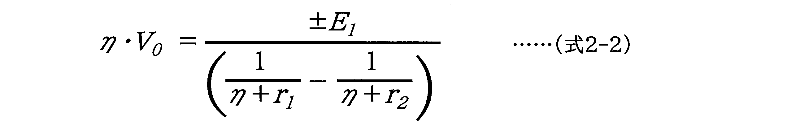
同様に、電極22と電極23との間で生じる電圧E
2は、式(1-1)で示した減衰式に基づいて、以下の式(2-3)のように表される。
Similarly, the voltage E 2 generated between the

ここで、r3は、信号源Vsから電極23までの距離である。
Here, r 3 is the distance from the signal source Vs to the
式(2-3)から、生体内の信号源Vsの信号強度V0は、以下の式(2-4)で表される。 From the formula (2-3), the signal strength V 0 of the signal source Vs in the living body is expressed by the following formula (2-4).

式(2-2)、(2-4)からV0を消去すると、以下の式(2-5)が導出される。 By eliminating V 0 from the equations (2-2) and (2-4), the following equation (2-5) is derived.

さらに、式(2-5)から、減衰係数ηは、以下の式(2-6)で表される。 Further, from the equation (2-5), the attenuation coefficient η is expressed by the following equation (2-6).

ここで、式(2-6)の右辺を、以下の式(2-7)のように定数Aで置き換えると、式(2-6)は、以下の式(2-8)のように表される。 Here, if the right side of the equation (2-6) is replaced with the constant A as in the following equation (2-7), the equation (2-6) is expressed as the following equation (2-8). Will be done.


従って、式(2-8)から、減衰係数ηは、以下の式(2-9)から求めることができる。 Therefore, from the equation (2-8), the attenuation coefficient η can be obtained from the following equation (2-9).

また、式(2-2)から、信号源Vsの信号強度V0は、以下の式(2-10)から求めることができる。 Further, from the equation (2-2), the signal strength V 0 of the signal source Vs can be obtained from the following equation (2-10).

式(2-9)及び式(2-7)から、減衰係数ηは、各電極間に生じるE 1、E 2、及び、信号源Vsから各電極までの距離r1、r2、r3を用いて求めることができる。 From equations (2-9) and (2-7), the attenuation coefficient η is the distance r 1 , r 2 , r 3 generated between each electrode, E 1 , E 2 , and the distance from the signal source Vs to each electrode. Can be obtained using.
ここで、信号源Vsの位置情報(x、y)は、後述する方法により検出することができる。従って、3つの電極21、22、23を含む平面内における各電極の位置情報(Xi,Yi)(i=1,2,3)と、信号源Vsの位置情報(x、y)から、信号源Vsと各電極21、22、23との距離ri(i=1,2,3)を算出することができる。
Here, the position information (x, y) of the signal source Vs can be detected by a method described later. Therefore, from the position information (X i , Y i ) (i = 1, 2, 3) of each electrode in the plane including the three
これにより、式(2-10)から、信号源Vsの信号強度V0は、式(2-9)により求めたηと、各電極間に生じた電圧E 1、E 2、及び信号源Vsと各電極までの距離r1、r2、r3を用いて求めることができる。 As a result, from the equation (2-10), the signal strength V 0 of the signal source Vs is the η obtained by the equation (2-9), the voltages E 1 and E 2 generated between the electrodes, and the signal source Vs. And the distances to each electrode r 1 , r 2 , r 3 can be used.
このように、本実施形態によれば、信号源Vsの位置情報(x,y)、信号源Vsを囲むように、生体表面の円周上に配置した3つの電極21、22、23の位置情報(Xi,Yi)(i=1,2,3)、及び各電極間に生じた電圧E
i(i=1,2)を用いて、式(1-1)で示した体内における信号源Vsの減衰式に基づいて、生体内の信号源Vsの信号強度V0を検出することができる。これにより、少ない数の電極を用いて、生体内で活動する組織の活動部位(信号源)の信号強度を検出することが可能となる。
As described above, according to the present embodiment, the position information (x, y) of the signal source Vs and the positions of the three
なお、本実施形態では、式(2-1)及び式(2-3)に示したように、各電極間に生じた電圧E 1、E 2を、各電極で測定した電圧の差分により求めているため、外部からのノイズをキャンセルすることができる。そのため、電極間に生じた電圧E iを、ノイズの影響を少なくして測定できるため、信号源Vsの信号強度をより精度良く検出することができる。 In this embodiment, as shown in the equations ( 2-1 ) and ( 2-3 ), the voltages E1 and E2 generated between the electrodes are obtained by the difference between the voltages measured by the electrodes. Therefore, it is possible to cancel the noise from the outside. Therefore, the voltage Ei generated between the electrodes can be measured with less influence of noise, and the signal strength of the signal source Vs can be detected more accurately.
(信号源の位置検出方法)
図4~図7を参照しながら、本実施形態における信号源Vsの信号強度検出方法に用いる信号源の位置検出方法について説明する。
(Method of detecting the position of the signal source)
The position detection method of the signal source used in the signal strength detection method of the signal source Vs in the present embodiment will be described with reference to FIGS. 4 to 7.
図4は、生体内の信号源Vsの位置を検出する方法を説明する電気回路網を示した図である。 FIG. 4 is a diagram showing an electric circuit network illustrating a method of detecting the position of a signal source Vs in a living body.
図4に示すように、生体10の表面に、3つの電極21、22、23を配置する。また、各電極21、22、23とグランド電位との間に、相互に切り替え可能な第1の外部抵抗及び第2の外部抵抗を並列接続する。ここでは、第1の外部抵抗の抵抗値を無限大とし、第2の外部抵抗の抵抗値をRgとしている。これにより、各電極21、22、23とグランド電位との間は、切り替え手段SWによって、外部抵抗Rgが接続されていない場合と、外部抵抗Rgが接続されている場合とに切り替えられる。なお、生体10の表面に、電極21、22、23で測定する電圧の影響を受けない位置にグランド電極20を配置し、これをグランド電位にしているが、必ずしも、生体10の表面に、グランド電極20を配置する必要はない。
As shown in FIG. 4, three
生体10の表面に配置した各電極21、22、23には、生体10内の信号源Vsからの電圧が発生し、その電圧をアンプ30で増幅して、出力電圧Voutが出力される。各電極21、22、23とアンプ30との間には、スイッチS1、S2、S3がそれぞれ配置され、各スイッチS1、S2、S3を順次、導通させることにより、各電極21、22、23に生じた電圧が、アンプ30の出力電圧Voutとして測定される。
A voltage from the signal source Vs in the living
図5に示すように、切り替え手段SW、及びスイッチS1、S2、S3を、それぞれ切り替える(ステップ1~ステップ6)。これにより、各電極21、22、23とグランド電位との間に、外部抵抗が接続されていないときに各電極21、22、23に生じる第1の電圧V1、V2、V3、及び各電極21、22、23とグランド電位との間に、外部抵抗Rgが接続されているときに各電極21、22、23に生じる第2の電圧V’1、V’2、V’3が測定される。なお、図5では、各電極21、22、23を、それぞれ、チャネルch1、ch2、ch3と表示している。
As shown in FIG. 5, the switching means SW and the switches S 1 , S 2 , and S 3 are switched (
図6は、複数の筋繊維40を囲むように、生体10の表面の円周10A上に、3つの電極21、22、23を配置した図で、信号源Vsと各電極21、22、23との間の内部抵抗を、それぞれ、Rb1、Rb2、Rb3と表している。
FIG. 6 is a diagram in which three
このとき、図5に示したステップ1において、電極21(チャネルch1)で生じる第1の電圧(外部抵抗が接続されていない場合)V1は、式(3-1)で与えられる。
At this time, in
![]()
![]()
一方、ステップ4において、電極21(チャネルch1)で生じる第2の電圧(外部抵抗Rgが接続されている場合)V’1は、アンプ30の入力抵抗Rinが非常に大きいとき、式(3-2)で与えられる。
On the other hand, in

ここで、Rb0は、信号源Vsとグランド電極20との間の内部抵抗を表す。
Here, R b0 represents the internal resistance between the signal source Vs and the
式(3-1)及び式(3-2)から、電極21(チャネルch1)において、外部抵抗Rgが接続されていない場合の第1の電圧V1と、外部抵抗Rgが接続されている場合の第2の電圧V’1との比V’1/V1(減衰比)は、式(3-3)で与えられる。 From the equations (3-1) and (3-2), in the electrode 21 (channel ch 1 ), the first voltage V1 when the external resistance Rg is not connected and the external resistance Rg are connected. The ratio V'1 / V 1 (attenuation ratio) to the second voltage V'1 in the case is given by the equation (3-3).

同様に、電極22(チャネルch2)において、外部抵抗Rgが接続されていない場合の第1の電圧V2と、外部抵抗Rgが接続されている場合の第2の電圧V’2との比V’2/V2(減衰比)、及び、電極23(チャネルch3)において、外部抵抗Rgが接続されていない場合の第1の電圧V3と、外部抵抗Rgが接続されている場合の第2の電圧V’3との比V’3/V3(減衰比)は、それぞれ、式(3-4)、式(3-5)で与えられる。 Similarly, in the electrode 22 (channel ch 2 ), the ratio of the first voltage V 2 when the external resistance Rg is not connected to the second voltage V ' 2 when the external resistance Rg is connected. In V'2 / V 2 ( attenuation ratio) and the electrode 23 (channel ch 3 ), when the first voltage V 3 when the external resistance Rg is not connected and the external resistance Rg are connected. The ratio V'3 / V 3 (attenuation ratio) to the second voltage V'3 is given by the equations (3-4) and (3-5), respectively.


ところで、生体10内の導電率が一様であると仮定すると、内部抵抗の抵抗値Rb1、Rb2、Rb3は、それぞれ、生体10内の信号源Vsと、各電極21、22、23との距離に比例すると考えられる。従って、式(3-3)、(3-4)、(3-5)から、生体10内の信号源Vsと、各電極21、22、23との距離L1、L2、L3は、それぞれ、式(3-6)、(3-7)、(3-8)で表される。
By the way, assuming that the conductivity in the living


ここで、βは、内部抵抗Rbiと距離Li(i=1、2、3)との比例定数で、生体10の導電率等で定まる。
Here, β is a constant of proportionality between the internal resistance R bi and the distance Li ( i = 1, 2, 3), and is determined by the conductivity of the living
式(3-6)、(3-7)、(3-8)に示すように、距離L1、L2、L3は、それぞれ、減衰比(V’1/V1、V’2/V2、V’3/V3)の逆数の関数として表される。そして、図7に示すように、信号源Vsは、各電極21、22、23を中心とする半径L1、L2、L3の円Q1、Q2、Q3の交点に存在すると考えられる。各電極21、22、23の位置座標を、(a1、b1)、(a2、b2)、(a3、b3)とすると、円Q1、Q2、Q3は、それぞれ、以下の式(3-9)、(3-10)、(3-11)で表される。
As shown in the equations (3-6), (3-7), and (3-8), the distances L 1 , L 2 , and L 3 have attenuation ratios ( V'1 / V 1 , V'2 /, respectively. It is expressed as a function of the reciprocal of V 2 , V'3 / V 3 ) . Then, as shown in FIG. 7, it is considered that the signal source Vs exists at the intersection of the circles Q 1 , Q 2 , and Q 3 having radii L 1 , L 2 , and L 3 centered on the


従って、式(3-6)、(3-7)、(3-8)で求めたL1、L2、L3を用いて、上記の式(3-9)、(3-10)、(3-11)は、以下の式(3-12)で表される3つの連立方程式になる。 Therefore, using L 1 , L 2 , and L 3 obtained by the equations (3-6), (3-7), and (3-8), the above equations (3-9), (3-10),. (3-11) becomes three simultaneous equations expressed by the following equation (3-12).

ここで、式(3-12)で表される3つの連立方程式の未知数は、信号源Vsの二次元座標(x、y)と、定数β、Rb0の4つになる。従って、Rb0を予め与えることによって、3つの連立方程式を解くことにより、信号源Vsの二次元座標(x、y)と、定数βを求めることができる。 Here, the unknowns of the three simultaneous equations represented by the equation (3-12) are the two-dimensional coordinates (x, y) of the signal source Vs and the constants β and R b0 . Therefore, by giving R b0 in advance, the two-dimensional coordinates (x, y) of the signal source Vs and the constant β can be obtained by solving three simultaneous equations.
このように、生体10の表面に配置した3つの電極21、22、23と、グランド電位との間に外部抵抗を並列接続し、その接続状態を切り替えて、各電極21、22、23に生じる電圧の比(減衰比)を測定することによって、生体10内の信号源Vsの2次元位置(x、y)を容易に検出することができる。これにより、少ない数の電極を用いて、生体内の信号源Vsの2次元位置を精度よく検出することができる。
In this way, an external resistor is connected in parallel between the three
また、内部抵抗Rbiと距離Li(i=1、2、3)との比例定数βを、上記の連立方程式を解くことによって求めることができる。そのため、比例定数βが、体内の組成に影響を受けて変動したり、あるいは、検出中に値が変化したりしても、生体内の信号源Vsの2次元位置を、より精度よく検出することができる。 Further, the proportionality constant β between the internal resistance R bi and the distance Li ( i = 1, 2, 3) can be obtained by solving the above simultaneous equations. Therefore, even if the proportionality constant β fluctuates due to the influence of the composition in the body or the value changes during detection, the two-dimensional position of the signal source Vs in the living body is detected more accurately. be able to.
なお、生体10内の信号源Vsは1つと仮定して説明したが、実際には、複数の信号源が同時に発生する場合もある。このような場合でも、これら信号源の電気信号の最も支配的な1点を信号源として求めることができる。
Although the description is based on the assumption that there is only one signal source Vs in the living
また、図5に示したように、切り替え手段SW、及びスイッチS1、S2、S3を切り替えて、各電極21、22、23における第1の電圧V1、V2、V3、及び第2の電圧V’1、V’2、V’3を順次測定している。従って、これらの切り替え時間内に、信号電Vsの電位が変化すると、信号源Vsの位置測定に誤差が生じるおそれがある。そのため、各電極及び外部抵抗の切り替えは、できるだけ高速で行うことが好ましい。例えば、1μs以下、望ましくは0.1μs以下で切り替えることが好ましい。
Further, as shown in FIG. 5, the switching means SW and the switches S1, S2, and S3 are switched to switch the first voltages V1 , V2, V3, and the second at the
なお、上記の説明では、第1の外部抵抗の抵抗値を無限大(非導通)とし、第2の外部抵抗の抵抗値をRgとしたが、第1の外部抵抗を、第2の外部抵抗と異なる大きさの抵抗値にしてもよい。 In the above description, the resistance value of the first external resistance is infinite (non-conducting) and the resistance value of the second external resistance is Rg, but the first external resistance is the second external resistance. The resistance value may be different from that of.
この場合、生体10の表面の円周上に3つの電極21、22、23を配置するとともに、各電極21、22、23とグランド電位との間に、相互に切り替え可能な第1の外部抵抗及び第2の外部抵抗を並列接続する。そして、各電極21、22、23とグランド電位との間に、第1の外部抵抗を並列接続したときに各電極21、22、23に生じる第1の電圧Vi(i=1,2,3)、及び各電極21、22、23とグランド電位との間に、第2の外部抵抗を並列接続したときに各電極21、22、23に生じる第2の電圧V’i(i=1,2,3)を測定する。そして、第1の電圧Vi及び第2の電圧V’iから比V1/V’i(i=1,2,3)を算出し、これら3つの比Vi/V’i(i=1,2,3)に基づいて、生体内の信号源Vsの位置を検出すればよい。
In this case, three
次に、図8~図10を参照しながら、本実施形態における信号源Vsの信号強度検出方法に用いる他の信号源位置検出方法について説明する。 Next, another signal source position detection method used in the signal intensity detection method of the signal source Vs in the present embodiment will be described with reference to FIGS. 8 to 10.
図8は、生体内の信号源Vsの位置を検出する方法を説明する電気回路網を示した図である。 FIG. 8 is a diagram showing an electric circuit network illustrating a method of detecting the position of a signal source Vs in a living body.
図8に示すように、生体10の表面に、3つの電極21、22、23を配置する。具体的には、図6に示したように、3つの電極21、22、23を、複数の筋繊維40を囲むように、生体10の表面の円周10A上に配置する。また、第1の電極21と第2の電極22との間、第2の電極22と第3の電極23との間、及び第3の電極23と第1の電極21との間に、それぞれ、相互に切り替え可能な第1の外部抵抗及び第2の外部抵抗を並列接続する。なお、本実施形態でも、第1の実施形態と同様に、第1の外部抵抗の抵抗値を無限大とし、第2の外部抵抗の抵抗値をRgとする。また、生体10の表面に、電極21、22、23で測定する電圧の影響を受けない位置にグランド電極20を配置し、これをグランド電位にしている。
As shown in FIG. 8, three
図8に示すように、各電極21、22、23と差動アンプ30との間に、スイッチS1、S2、S3、及びSS1、SS2、SS3が配置されている。そして、各スイッチS1、S2、S3、及びSS1、SS2、SS3を、図9に示すように、順次、導通させることによって、第1の電極21と第2の電極22との間、第2の電極22と第3の電極23との間、及び第3の電極23と第1の電極21との間に生じた電圧が、差動アンプ30の出力電圧Voutとして測定される。また、各電極間は、切り替え手段SWによって、外部抵抗が接続されていない場合と、外部抵抗Rgが接続されている場合とに切り替えられる。これにより、図9に示すように、切り替え手段SW、及び各スイッチS1、S2、S3、SS1、SS2、SS3を、それぞれ切り替えることによって(ステップ1~ステップ6)、各電極間に外部抵抗Rgが接続されていないときに各電極間に生じる第1の電圧V12、V23、V31、及び各電極間に外部抵抗Rgが接続されているときに各電極間に生じる第2の電圧V’12、V’23、V’31)が測定される。なお、図8には、各電極21、22、23を、それぞれ、チャネルch1、ch2、ch3と表示している。
As shown in FIG . 8 , switches S1, S2, S3 , and SS1 , SS2 , and SS3 are arranged between the
図9に示したステップ1において、電極21と電極22との間(チャネルch1とch2との間)で生じる第1の電圧(外部抵抗が接続されていない場合)V12は、式(4-1)で与えられる。
In
![]()
![]()
一方、ステップ4において、電極21と電極22との間(チャネルch1とch2との間)で生じる第2の電圧(外部抵抗Rgが接続されている場合)V’12は、アンプ30の入力抵抗Rinが非常に大きいとき、式(4-2)で与えられる。
On the other hand, in

ここで、Rb1及びRb2は、それぞれ、生体10内の信号源Vsと電極21(チャネルch1)の間の内部抵抗、及び信号源Vsと電極22(チャネルch2)の間の内部抵抗を表す。
Here, R b1 and R b2 have an internal resistance between the signal source Vs and the electrode 21 (channel ch 1 ) in the living
式(4-1)及び式(4-2)から、電極21と電極22との間(チャネルch1とch2との間)で生じる第1の電圧V12と第2の電圧V’12の比V’12/V12(減衰比)は、式(4-3)で与えられる。
From equations (4-1) and (4-2), the first voltage V 12 and the second voltage V'12 generated between the

同様に、電極22と電極23との間(チャネルch2とch3との間)で生じる第1の電圧V23と第2の電圧V’23の比V’23/V23(減衰比)、及び、電極23と電極21との間(チャネルch3とch1との間)で生じる第1の電圧V31と第2の電圧V’31の比V’31/V31(減衰比)は、それぞれ、式(4-4)、(4-5)で与えられる。
Similarly, the ratio of the first voltage V 23 to the second voltage V'23 generated between the


ここで、Rb3は、生体10内の信号源Vsと電極23(ch3)との間の内部抵抗の抵抗値を表す。
Here, R b3 represents the resistance value of the internal resistance between the signal source Vs in the living
各電極間に生じる電圧の測定において、生体10内の内部抵抗は、各電極と信号源との間の内部抵抗の和で表される。例えば、電極21と電極22との間(チャネルch1とch2との間)で生じる第1の電圧V12及び第2の電圧V’12の測定において、生体10内の内部抵抗は、Rb1+Rb2で表される。
In the measurement of the voltage generated between each electrode, the internal resistance in the living
ここで、生体10内の導電率が一様であると仮定すると、内部抵抗の和(Rb1+Rb2)は、電極21と信号源Vsとの距離D1と、電極22と信号源Vsとの距離D2との和(D1+D2)に比例すると考えられる。従って、式(2-3)、(2-4)、(2-5)から、各電極と信号源Vsとの距離の和(D1+D2)、(D2+D3)、(D3+D1)は、それぞれ、式(4-6)、(4-7)、(4-8)で表される。
Here, assuming that the conductivity in the living


ここで、αは、内部抵抗Rbiと距離Di(i=1、2、3)との比例定数で、生体10の導電率等で定まる。
Here, α is a constant of proportionality between the internal resistance R bi and the distance Di ( i = 1, 2, 3), and is determined by the conductivity of the living
式(4-6)、(4-7)、(4-8)に示すように、各電極と信号源Vsとの距離の和(D1+D2)、(D2+D3)、(D3+D1)は、それぞれ、減衰比(V’12/V12)、(V’23/V23)、(V’31/V31)の逆数の関数として表される。そして、図10に示すように、信号源Vsは、電極21、22(チャネルch1、ch2)を焦点とする楕円P
1、電極22、23(チャネルch2、ch3)を焦点とする楕円P
2、及び電極23、21(チャネルch3、ch1)を焦点とする楕円P
3の交点に存在すると考えられる。
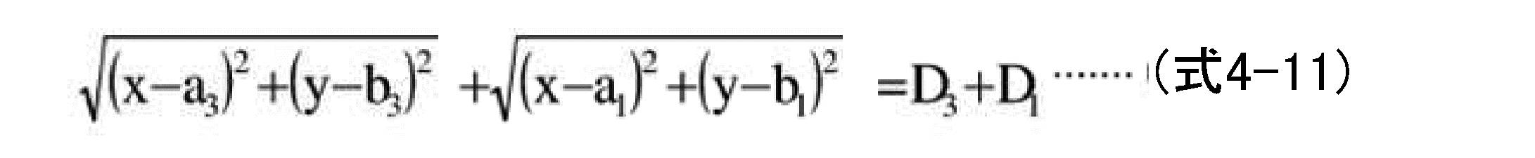
As shown in equations (4-6), (4-7), and (4-8), the sum of the distances between each electrode and the signal source Vs (D 1 + D 2 ), (D 2 + D 3 ), (D). 3 + D 1 ) is expressed as a function of the reciprocals of the damping ratio ( V'12 / V12 ), ( V'23 / V23 ), and ( V'31 / V31 ), respectively. Then, as shown in FIG. 10 , the signal source Vs focuses on the ellipses P1 and the
各電極21、22、23の位置座標を、(a1、b1)、(a2、b2)、(a3、b3)とすると、楕円P
1、P
2、P
3は、それぞれ、以下の式(4-9)、(4-10)、(42-11)で表される。
Assuming that the position coordinates of the


従って、式(4-6)、(4-7)、(4-8)で求めた(D1+D2)、(D2+D3)、(D3+D1)を用いて、以下の式(4-12)で表される3つの連立方程式を解くことによって、信号源Vsの二次元座標(x、y)を求めることができる。 Therefore, using (D 1 + D 2 ), (D 2 + D 3 ), and (D 3 + D 1 ) obtained by the equations (4-6), (4-7), and (4-8), the following equations are used. By solving the three simultaneous equations represented by (4-12), the two-dimensional coordinates (x, y) of the signal source Vs can be obtained.

式(4-12)には、信号源Vsとグランド電極20との間の内部抵抗Rb0が式中に入っていない。また、式(4-12)で表される3つの連立方程式の未知数は、信号源Vsの二次元座標(x、y)と、定数αの3つになる。従って、式(4-12)で表される3つの連立方程式を解くことによって、信号源Vsの二次元座標(x、y)と、定数αを求めることができる。
In equation (4-12), the internal resistance R b0 between the signal source Vs and the
上記の方法によれば、信号源Vsの二次元座標(x、y)を求める際に、2つの定数、すなわち、内部抵抗Rbiと距離Li(i=1、2、3)との比例定数α、及び、信号源Vsとグランド電極20との間の内部抵抗Rb0を、予め求めておく必要がなく、簡便に、生体内の信号源Vsの二次元座標を求めることができる。
According to the above method, when the two-dimensional coordinates (x, y) of the signal source Vs are obtained, the two constants, that is, the proportionality between the internal resistance R bi and the distance Li ( i = 1, 2, 3). It is not necessary to obtain the constant α and the internal resistance R b0 between the signal source Vs and the
(生体内信号強度検出装置)
図11は、本発明の他の実施形態における生体内信号強度検出装置の構成を示すブロック図で、生体表面に配置される電極に生じる電圧によって、生体内の信号源の信号強度を検出する装置である。なお、本実施形態で対象とする生体内の信号源は、複数の筋繊維からなる線状の信号源である。
(In-vivo signal strength detection device)
FIG. 11 is a block diagram showing a configuration of an in-vivo signal intensity detection device according to another embodiment of the present invention, and is a device that detects the signal intensity of a signal source in the living body by a voltage generated in an electrode arranged on the surface of the living body. Is. The signal source in the living body targeted in the present embodiment is a linear signal source composed of a plurality of muscle fibers.
図11に示すように、本実施形態における生体内信号強度検出装置100は、少なくとも2つの電極が連結された電極ユニット110を備え、かかる電極ユニット110は、図図2に示したように、複数の筋繊維(線状の信号源)40を囲むように、生体10の表面の円周10A上に配置される。
As shown in FIG. 11, the in-vivo signal
生体内信号強度検出装置100は、さらに、信号源Vsの位置情報(x,y)を検出する手段120と、各電極とグランド電位との間、又は、各電極間に生じる電圧Vi(i=1,2)を測定する手段130と、信号源Vsと各電極との距離ri(i=1,2)を算出する手段140と、信号源Vsの信号強度を検出する手段150とを備えている。
The in-vivo signal
信号強度検出手段150では、電圧測定手段130で測定された電圧Vi(i=1,2)、距離算出手段140で算出された距離ri(i=1,2)、及び式(1-1)で示した生体内における信号源の減衰式に基づいて、信号源Vsの信号強度を検出する。
In the signal
ここで、信号強度の検出は、上記の第1の実施形態または第2の実施形態において説明した生体内信号強度検出方法を用いて検出することができる。 Here, the signal strength can be detected by using the in-vivo signal strength detection method described in the first embodiment or the second embodiment described above.
以上、本発明を好適な実施形態により説明してきたが、こうした記述は限定事項ではなく、もちろん、種々の改変が可能である。例えば、上記実施形態では、体内における信号源の減衰式に、式(1-1)を用いたが、必ずしもこれに限定されない。 Although the present invention has been described above in terms of preferred embodiments, such a description is not a limitation, and of course, various modifications can be made. For example, in the above embodiment, the equation (1-1) is used as the attenuation equation of the signal source in the body, but the present invention is not necessarily limited to this.
また、上記実施形態では、信号源の信号強度の検出を、複数の信号源を囲むように、少なくとも2つ以上の電極を配置して行ったが、さらに一つ以上の電極を配置して、信号源の位置検出を行ってもよい。 Further, in the above embodiment, the signal strength of the signal source is detected by arranging at least two or more electrodes so as to surround the plurality of signal sources, but further arranging one or more electrodes. The position of the signal source may be detected.
また、上記実施形態では、信号源Vsの位置情報(x、y)の検出を、図4~図7、若しくは、図8~図10を参照しながら説明した方法、すなわち、複数の信号源を囲むように、少なくとも3つ以上の電極を配置し、各電極とグランド電位との間に、抵抗値の異なる2つの外部抵抗を並列に接続して、それぞれの外部抵抗に並列接続したときに各電極に生じる電圧Vk(k=1,2,3)及び電圧V’k(k=1,2,3)を測定し、電圧比Vk/V’k(k=1,2,3)に基づいて行う方法を説明したが、必ずしもこれに限定されない。例えば、生体表面に多数の電極を格子状に配置し、各電極で測定した表面電位と、MRI(Magnetic Resonance Imaging:磁気共鳴画像)や、CT(Computed Tomography:コンピュータ断層撮影)等で得られた生体の画像データに基づいて、体内の電位分布を解析することによって、生体内の信号源の位置情報を求める方法を用いてもよい。 Further, in the above embodiment, the method described for detecting the position information (x, y) of the signal source Vs with reference to FIGS. 4 to 7 or 8 to 10, that is, a plurality of signal sources is used. At least three electrodes are placed so as to surround each other, and two external resistors with different resistance values are connected in parallel between each electrode and the ground potential, and each is connected in parallel to each external resistor. The voltage V k (k = 1,2,3) and the voltage V'k ( k = 1,2,3) generated at the electrodes are measured, and the voltage ratio V k / V'k (k = 1,2,3). Although the method based on the above has been described, the method is not necessarily limited to this. For example, a large number of electrodes are arranged in a grid pattern on the surface of a living body, and the surface potential measured by each electrode is obtained by MRI (Magnetic Resonance Imaging), CT (Computed Tomography), or the like. A method of obtaining the position information of the signal source in the living body may be used by analyzing the potential distribution in the living body based on the image data of the living body.
10 生体
10A 円周
20 グランド電極
21 第1の電極(チャネルch1)
22 第2の電極(チャネルch2)
23 第3の電極(チャネルch3)
30 差動アンプ
40 筋繊維
100 生体内信号強度検出装置
110 電極ユニット
120 位置情報検出手段
130 電圧測定手段
140 距離算出手段
150 信号強度検出手段
10 Living body
10A circumference
20 ground electrode
21 First electrode (channel ch 1 )
22 Second electrode (channel ch 2 )
23 Third electrode (channel ch 3 )
30 differential amplifier
40 muscle fiber
100 In-vivo signal strength detector
110 Electrode unit
120 Location information detection means
130 Voltage measuring means
140 Distance calculation means
150 Signal strength detecting means
Claims (2)
前記生体内の信号源は、複数の筋繊維からなる線状の信号源であって、
前記複数の信号源を囲むように、前記生体表面の円周上に配置する、2つの電極が連結された電極ユニットと、
前記生体表面の円周上に配置された前記2つの電極を含む平面内における前記信号源の位置情報(x,y)を検出する手段と、
前記各電極とグランド電位との間に生じる電圧E1、E2を測定する手段と、
前記2つの電極を含む平面内における各電極の位置情報、及び、前記信号源の位置情報(x,y)から、前記信号源と前記各電極との距離r1、r2を算出する手段と、
を備え、
前記信号源の位置情報(x、y)を検出する手段は、
前記2つの電極を配置した円周上に、一つの電極を配置し、前記各電極とグランド電位との間に、第1の外部抵抗及び第2の外部抵抗を、それぞれ切り替え可能に並列接続し、前記各電極とグランド電位との間に、前記第1の外部抵抗を接続したときに生じる第1の電圧V1、V2、V3、及び、前記各電極とグランド電位との間に、前記第2の外部抵抗を接続したときに生じる第2の電圧V'1、V'2、V'3を測定する手段と、
前記第1の電圧V1、V2、V3及び前記第2の電圧V'1、V'2、V'3から、比V1/V'1、V2/V'2、V3/V'3を算出する手段と、
前記各電極が配置された生体表面の円周に沿った断面内における前記各電極の位置座標を(a1、b1)、(a2、b2)、(a3、b3)、前記第1の外部抵抗の大きさを無限大、前記第2の外部抵抗の大きさをRg、前記信号源とグランド電極との間の内部抵抗をRb0、βを生体の導電率で決まる定数としたとき、前記信号源の前記断面内における位置(x、y)を、下記の連立方程式(1)を解くことによって検出する手段と
を含み、
生体内の信号源の信号強度V0は、下記の式(2)、(3)に基づいて検出する、生体内信号強度検出装置。


The signal source in the living body is a linear signal source composed of a plurality of muscle fibers.
An electrode unit in which two electrodes are connected and arranged on the circumference of the living body surface so as to surround the plurality of signal sources.
A means for detecting the position information (x, y) of the signal source in a plane including the two electrodes arranged on the circumference of the living body surface, and
A means for measuring the voltages E 1 and E 2 generated between each of the electrodes and the ground potential, and
As a means for calculating the distances r1 and r2 between the signal source and each electrode from the position information of each electrode in the plane including the two electrodes and the position information (x, y) of the signal source. ,
Equipped with
The means for detecting the position information (x, y) of the signal source is
One electrode is arranged on the circumference on which the two electrodes are arranged, and the first external resistance and the second external resistance are connected in parallel so as to be switchable between each of the electrodes and the ground potential. , The first voltage V 1 , V 2 , V 3 generated when the first external resistance is connected between each of the electrodes and the ground potential, and between each of the electrodes and the ground potential. A means for measuring the second voltages V'1 , V'2 , and V'3 generated when the second external resistor is connected, and
From the first voltage V 1 , V 2 , V 3 and the second voltage V'1 , V'2, V'3 , the ratio V 1 / V'1 , V 2 / V'2 , V 3 /. Means for calculating V'3 and
The position coordinates of the electrodes in the cross section along the circumference of the living body surface on which the electrodes are arranged are (a 1 , b 1 ), (a 2 , b 2 ), (a 3 , b 3 ), and the above. The magnitude of the first external resistance is infinite, the magnitude of the second external resistance is R g , the internal resistance between the signal source and the ground electrode is R b0 , and β is a constant determined by the conductivity of the living body. , Including means for detecting the position (x, y) of the signal source in the cross section by solving the following simultaneous equations ( 1 ).
The signal strength V 0 of the signal source in the living body is an in-vivo signal strength detecting device that detects based on the following equations ( 2 ) and ( 3 ).
前記生体内の信号源は、複数の筋繊維からなる線状の信号源であって、
前記複数の信号源を囲むように、前記生体表面の円周上に配置する、2つの電極が連結された電極ユニットと、
前記生体表面の円周上に配置された前記2つの電極を含む平面内における前記信号源の位置情報(x、y)を検出する手段と、
前記各電極とグランド電位との間に生じる電圧E1、E2を測定する手段と、
前記2つの電極を含む平面内における各電極の位置情報、及び、前記信号源の位置情報(x、y)から、前記信号源と前記各電極との距離r1、r2を算出する手段と、
を備え、
前記信号源の位置情報(x、y)を検出する手段は、
前記2つの電極を配置した円周上に、一つの電極を配置し、前記生体表面の円周上に配置する3つの電極を、第1の電極、第2の電極、及び第3の電極としたとき、前記第1の電極と前記第2の電極との間、前記第2の電極と前記第3の電極との間、及び前記第3の電極と前記第1の電極との間に、第1の外部抵抗及び第2の外部抵抗を、それぞれ切り替え可能に並列接続し、前記各電極間に前記第1の外部抵抗を並列接続したときに各電極間に生じる第1の電圧V12、V23、V31、及び前記各電極間に前記第2の外部抵抗を並列接続したときに各電極間に生じる第2の電圧V'12、V'23、V'31を測定する手段と、
前記第1の電圧V12、V23、V31及び前記第2の電圧V'12、V'23、V'31から、それぞれ比V12/V'12、V23/V'23、V31/V'31を算出する手段と、
前記各電極が配置された生体表面の円周に沿った断面内における前記各電極の位置座標を(a1、b1)、(a2、b2)、(a3、b3)、前記第1の外部抵抗の大きさを無限大、前記第2の外部抵抗の大きさをRg、αを生体の導電率で決まる定数としたとき、前記信号源の前記断面内における位置(x、y)を、下記の連立方程式(4)を解くことによって検出する手段と、
を含み、
生体内の信号源の信号強度V0は、下記の式(5)、(6)に基づいて検出する、生体内信号強度検出装置。


The signal source in the living body is a linear signal source composed of a plurality of muscle fibers.
An electrode unit in which two electrodes are connected and arranged on the circumference of the living body surface so as to surround the plurality of signal sources.
A means for detecting the position information (x, y) of the signal source in a plane including the two electrodes arranged on the circumference of the living body surface, and
A means for measuring the voltages E 1 and E 2 generated between each of the electrodes and the ground potential, and
As a means for calculating the distances r1 and r2 between the signal source and each electrode from the position information of each electrode in the plane including the two electrodes and the position information (x, y) of the signal source. ,
Equipped with
The means for detecting the position information (x, y) of the signal source is
One electrode is arranged on the circumference on which the two electrodes are arranged, and the three electrodes arranged on the circumference of the living body surface are the first electrode, the second electrode, and the third electrode. Then, between the first electrode and the second electrode, between the second electrode and the third electrode, and between the third electrode and the first electrode, A first voltage V 12 generated between the electrodes when the first external resistance and the second external resistance are connected in parallel so as to be switchable and the first external resistance is connected in parallel between the electrodes. V 23 , V 31 , and means for measuring the second voltages V'12 , V'23 , and V'31 generated between the electrodes when the second external resistor is connected in parallel between the electrodes.
From the first voltage V 12 , V 23 , V 31 and the second voltage V'12 , V'23 , V'31, the ratios V 12 / V'12 , V 23 / V'23 , V 31 respectively. Means for calculating / V'31 and
The position coordinates of the electrodes in the cross section along the circumference of the living body surface on which the electrodes are arranged are (a 1 , b 1 ), (a 2 , b 2 ), (a 3 , b 3 ), and the above. When the magnitude of the first external resistance is infinite, the magnitude of the second external resistance is R g , and α is a constant determined by the conductivity of the living body, the position (x,) of the signal source in the cross section. A means for detecting y) by solving the following simultaneous equations ( 4 ),
Including
The signal strength V 0 of the signal source in the living body is an in-vivo signal strength detecting device that detects based on the following equations ( 5 ) and ( 6 ).
Priority Applications (1)
| Application Number | Priority Date | Filing Date | Title |
|---|---|---|---|
| JP2017047113A JP6991498B2 (en) | 2017-03-13 | 2017-03-13 | In-vivo signal strength detector |
Applications Claiming Priority (1)
| Application Number | Priority Date | Filing Date | Title |
|---|---|---|---|
| JP2017047113A JP6991498B2 (en) | 2017-03-13 | 2017-03-13 | In-vivo signal strength detector |
Publications (2)
| Publication Number | Publication Date |
|---|---|
| JP2018149056A JP2018149056A (en) | 2018-09-27 |
| JP6991498B2 true JP6991498B2 (en) | 2022-01-12 |
Family
ID=63679774
Family Applications (1)
| Application Number | Title | Priority Date | Filing Date |
|---|---|---|---|
| JP2017047113A Active JP6991498B2 (en) | 2017-03-13 | 2017-03-13 | In-vivo signal strength detector |
Country Status (1)
| Country | Link |
|---|---|
| JP (1) | JP6991498B2 (en) |
Citations (7)
| Publication number | Priority date | Publication date | Assignee | Title |
|---|---|---|---|---|
| JP2007268034A (en) | 2006-03-31 | 2007-10-18 | Ritsumeikan | Biological signal measuring method and apparatus |
| WO2010097894A1 (en) | 2009-02-24 | 2010-09-02 | 学校法人立命館 | Bioelectric potential estimating apparatus using impedance switching type multipoint surface electrode, and method therefor |
| JP2011030991A (en) | 2009-07-29 | 2011-02-17 | Hokkaido Research Organization | Muscular active mass measuring device |
| JP2013121369A (en) | 2011-12-09 | 2013-06-20 | Sony Corp | Input device and calibration method |
| US20150165269A1 (en) | 2012-04-27 | 2015-06-18 | Fibrux Oy | Method and device for measuring muscle signals |
| WO2016075726A1 (en) | 2014-11-14 | 2016-05-19 | 東レエンジニアリング株式会社 | Method for detecting position of signal source in living body, and device for detecting position of signal source in living body |
| JP2016159090A (en) | 2015-03-05 | 2016-09-05 | 東レエンジニアリング株式会社 | In vivo signal source position detection apparatus and in vivo signal source position detection method |
Family Cites Families (1)
| Publication number | Priority date | Publication date | Assignee | Title |
|---|---|---|---|---|
| JPS59200632A (en) * | 1983-04-26 | 1984-11-14 | 工業技術院長 | Apparatus for detecting nerve muscle junction distribution by muscle potential multi-point measurement |
-
2017
- 2017-03-13 JP JP2017047113A patent/JP6991498B2/en active Active
Patent Citations (7)
| Publication number | Priority date | Publication date | Assignee | Title |
|---|---|---|---|---|
| JP2007268034A (en) | 2006-03-31 | 2007-10-18 | Ritsumeikan | Biological signal measuring method and apparatus |
| WO2010097894A1 (en) | 2009-02-24 | 2010-09-02 | 学校法人立命館 | Bioelectric potential estimating apparatus using impedance switching type multipoint surface electrode, and method therefor |
| JP2011030991A (en) | 2009-07-29 | 2011-02-17 | Hokkaido Research Organization | Muscular active mass measuring device |
| JP2013121369A (en) | 2011-12-09 | 2013-06-20 | Sony Corp | Input device and calibration method |
| US20150165269A1 (en) | 2012-04-27 | 2015-06-18 | Fibrux Oy | Method and device for measuring muscle signals |
| WO2016075726A1 (en) | 2014-11-14 | 2016-05-19 | 東レエンジニアリング株式会社 | Method for detecting position of signal source in living body, and device for detecting position of signal source in living body |
| JP2016159090A (en) | 2015-03-05 | 2016-09-05 | 東レエンジニアリング株式会社 | In vivo signal source position detection apparatus and in vivo signal source position detection method |
Also Published As
| Publication number | Publication date |
|---|---|
| JP2018149056A (en) | 2018-09-27 |
Similar Documents
| Publication | Publication Date | Title |
|---|---|---|
| US6246230B1 (en) | Non-contact position sensor | |
| RU2677623C2 (en) | Methods for assessing health conditions using single coil magnetic induction tomography imaging | |
| JP2007309930A (en) | X-ray detector and method of operating X-ray detector | |
| JP2012501779A (en) | Method and system for magnetically induced tomography | |
| KR20010005556A (en) | Impedance-to-voltage converter | |
| EP2549744A2 (en) | Method of stitching and linearization of multisensor detectors gain characteristics | |
| RU2617270C1 (en) | Coil for visualisation by method of magnetic induction tomography | |
| TW201801674A (en) | Post processing system and post processing method of electrical impedance tomography images | |
| JP6770266B2 (en) | In-vivo signal source detection method and in-vivo signal source detection device | |
| JP6492103B2 (en) | In vivo signal source position detection method and in vivo signal source position detection apparatus | |
| EP0094113A2 (en) | Tomography | |
| JP6991498B2 (en) | In-vivo signal strength detector | |
| US9599509B2 (en) | Spectroscopy system with displacement compensation and spectroscopy method using the spectroscopy system | |
| JP6518084B2 (en) | In-vivo signal source position detection device and in-vivo signal source position detection method | |
| JP6184925B2 (en) | Radiation image analysis apparatus, method, and program | |
| CN107548294A (en) | Medical imaging apparatus | |
| JP3396663B2 (en) | Body fat measurement device | |
| JP7117727B2 (en) | In vivo signal source position detection method | |
| JP2019030732A (en) | In-vivo signal source position detection method and in-vivo signal source position detection device | |
| Krumb et al. | Leveraging spatial uncertainty for online error compensation in EMT | |
| Bor et al. | Comparison of different phantoms used in digital diagnostic imaging | |
| Naushad et al. | Analysing the performance of EIT images using the point spread function | |
| Brown et al. | Detecting repetitions and time features in resistance training using triaxial accelerometry | |
| CN107622516A (en) | Post-processing system and post-processing method for electrical impedance tomography images | |
| KR102331619B1 (en) | Device and Method for Estimating Muscle Activity Using Switching of Multiple Electrodes |
Legal Events
| Date | Code | Title | Description |
|---|---|---|---|
| A621 | Written request for application examination |
Free format text: JAPANESE INTERMEDIATE CODE: A621 Effective date: 20200212 |
|
| A977 | Report on retrieval |
Free format text: JAPANESE INTERMEDIATE CODE: A971007 Effective date: 20201216 |
|
| A131 | Notification of reasons for refusal |
Free format text: JAPANESE INTERMEDIATE CODE: A131 Effective date: 20201222 |
|
| A521 | Request for written amendment filed |
Free format text: JAPANESE INTERMEDIATE CODE: A523 Effective date: 20210208 |
|
| A131 | Notification of reasons for refusal |
Free format text: JAPANESE INTERMEDIATE CODE: A131 Effective date: 20210309 |
|
| A521 | Request for written amendment filed |
Free format text: JAPANESE INTERMEDIATE CODE: A523 Effective date: 20210331 |
|
| A131 | Notification of reasons for refusal |
Free format text: JAPANESE INTERMEDIATE CODE: A131 Effective date: 20210824 |
|
| A521 | Request for written amendment filed |
Free format text: JAPANESE INTERMEDIATE CODE: A523 Effective date: 20211022 |
|
| TRDD | Decision of grant or rejection written | ||
| A01 | Written decision to grant a patent or to grant a registration (utility model) |
Free format text: JAPANESE INTERMEDIATE CODE: A01 Effective date: 20211109 |
|
| A61 | First payment of annual fees (during grant procedure) |
Free format text: JAPANESE INTERMEDIATE CODE: A61 Effective date: 20211129 |
|
| R150 | Certificate of patent or registration of utility model |
Ref document number: 6991498 Country of ref document: JP Free format text: JAPANESE INTERMEDIATE CODE: R150 |