JP6991155B2 - Connection test of blood processing device II - Google Patents
Connection test of blood processing device II Download PDFInfo
- Publication number
- JP6991155B2 JP6991155B2 JP2018555740A JP2018555740A JP6991155B2 JP 6991155 B2 JP6991155 B2 JP 6991155B2 JP 2018555740 A JP2018555740 A JP 2018555740A JP 2018555740 A JP2018555740 A JP 2018555740A JP 6991155 B2 JP6991155 B2 JP 6991155B2
- Authority
- JP
- Japan
- Prior art keywords
- blood
- dialyzer
- access
- control device
- flow
- Prior art date
- Legal status (The legal status is an assumption and is not a legal conclusion. Google has not performed a legal analysis and makes no representation as to the accuracy of the status listed.)
- Active
Links
- 239000008280 blood Substances 0.000 title claims description 262
- 210000004369 blood Anatomy 0.000 title claims description 262
- 238000012545 processing Methods 0.000 title claims description 176
- 238000012360 testing method Methods 0.000 title claims description 44
- 239000012530 fluid Substances 0.000 claims description 158
- 230000017531 blood circulation Effects 0.000 claims description 80
- 230000008859 change Effects 0.000 claims description 75
- 238000000034 method Methods 0.000 claims description 55
- 230000002441 reversible effect Effects 0.000 claims description 45
- 230000002792 vascular Effects 0.000 claims description 43
- 238000000502 dialysis Methods 0.000 claims description 39
- 239000012528 membrane Substances 0.000 claims description 38
- 238000001727 in vivo Methods 0.000 claims description 22
- 238000011144 upstream manufacturing Methods 0.000 claims description 21
- 239000000126 substance Substances 0.000 claims description 16
- 230000000747 cardiac effect Effects 0.000 claims description 14
- 210000004204 blood vessel Anatomy 0.000 claims description 10
- 238000012546 transfer Methods 0.000 claims description 7
- 239000000463 material Substances 0.000 claims description 5
- 230000010287 polarization Effects 0.000 claims description 5
- 238000002835 absorbance Methods 0.000 claims description 4
- 238000012790 confirmation Methods 0.000 claims description 3
- 238000004364 calculation method Methods 0.000 claims description 2
- 238000011017 operating method Methods 0.000 claims 2
- 230000000704 physical effect Effects 0.000 claims 1
- 230000006870 function Effects 0.000 description 20
- 238000004458 analytical method Methods 0.000 description 16
- 230000035699 permeability Effects 0.000 description 14
- 238000005086 pumping Methods 0.000 description 12
- 238000005259 measurement Methods 0.000 description 11
- 238000011156 evaluation Methods 0.000 description 7
- 230000008569 process Effects 0.000 description 7
- 239000000385 dialysis solution Substances 0.000 description 6
- 239000007787 solid Substances 0.000 description 6
- XSQUKJJJFZCRTK-UHFFFAOYSA-N Urea Chemical compound NC(N)=O XSQUKJJJFZCRTK-UHFFFAOYSA-N 0.000 description 5
- 239000004202 carbamide Substances 0.000 description 4
- 238000001514 detection method Methods 0.000 description 4
- 239000003550 marker Substances 0.000 description 4
- 238000000926 separation method Methods 0.000 description 4
- XLYOFNOQVPJJNP-UHFFFAOYSA-N water Substances O XLYOFNOQVPJJNP-UHFFFAOYSA-N 0.000 description 4
- 208000020832 chronic kidney disease Diseases 0.000 description 3
- 208000022831 chronic renal failure syndrome Diseases 0.000 description 3
- 238000005516 engineering process Methods 0.000 description 3
- 238000002615 hemofiltration Methods 0.000 description 3
- 150000002500 ions Chemical class 0.000 description 3
- 238000004088 simulation Methods 0.000 description 3
- 206010016717 Fistula Diseases 0.000 description 2
- DGAQECJNVWCQMB-PUAWFVPOSA-M Ilexoside XXIX Chemical compound C[C@@H]1CC[C@@]2(CC[C@@]3(C(=CC[C@H]4[C@]3(CC[C@@H]5[C@@]4(CC[C@@H](C5(C)C)OS(=O)(=O)[O-])C)C)[C@@H]2[C@]1(C)O)C)C(=O)O[C@H]6[C@@H]([C@H]([C@@H]([C@H](O6)CO)O)O)O.[Na+] DGAQECJNVWCQMB-PUAWFVPOSA-M 0.000 description 2
- FAPWRFPIFSIZLT-UHFFFAOYSA-M Sodium chloride Chemical compound [Na+].[Cl-] FAPWRFPIFSIZLT-UHFFFAOYSA-M 0.000 description 2
- DDRJAANPRJIHGJ-UHFFFAOYSA-N creatinine Chemical compound CN1CC(=O)NC1=N DDRJAANPRJIHGJ-UHFFFAOYSA-N 0.000 description 2
- 238000010586 diagram Methods 0.000 description 2
- 230000000694 effects Effects 0.000 description 2
- 238000001914 filtration Methods 0.000 description 2
- 230000003890 fistula Effects 0.000 description 2
- 230000014509 gene expression Effects 0.000 description 2
- 239000000203 mixture Substances 0.000 description 2
- 238000012544 monitoring process Methods 0.000 description 2
- 230000002572 peristaltic effect Effects 0.000 description 2
- 238000000746 purification Methods 0.000 description 2
- 230000000717 retained effect Effects 0.000 description 2
- 229910052708 sodium Inorganic materials 0.000 description 2
- 239000011734 sodium Substances 0.000 description 2
- 238000012795 verification Methods 0.000 description 2
- WQZGKKKJIJFFOK-GASJEMHNSA-N Glucose Natural products OC[C@H]1OC(O)[C@H](O)[C@@H](O)[C@@H]1O WQZGKKKJIJFFOK-GASJEMHNSA-N 0.000 description 1
- 229930003779 Vitamin B12 Natural products 0.000 description 1
- 238000010521 absorption reaction Methods 0.000 description 1
- 230000009471 action Effects 0.000 description 1
- 230000003213 activating effect Effects 0.000 description 1
- 238000003491 array Methods 0.000 description 1
- 102000015736 beta 2-Microglobulin Human genes 0.000 description 1
- 108010081355 beta 2-Microglobulin Proteins 0.000 description 1
- 230000036770 blood supply Effects 0.000 description 1
- 239000003990 capacitor Substances 0.000 description 1
- 210000000748 cardiovascular system Anatomy 0.000 description 1
- FDJOLVPMNUYSCM-WZHZPDAFSA-L cobalt(3+);[(2r,3s,4r,5s)-5-(5,6-dimethylbenzimidazol-1-yl)-4-hydroxy-2-(hydroxymethyl)oxolan-3-yl] [(2r)-1-[3-[(1r,2r,3r,4z,7s,9z,12s,13s,14z,17s,18s,19r)-2,13,18-tris(2-amino-2-oxoethyl)-7,12,17-tris(3-amino-3-oxopropyl)-3,5,8,8,13,15,18,19-octamethyl-2 Chemical compound [Co+3].N#[C-].N([C@@H]([C@]1(C)[N-]\C([C@H]([C@@]1(CC(N)=O)C)CCC(N)=O)=C(\C)/C1=N/C([C@H]([C@@]1(CC(N)=O)C)CCC(N)=O)=C\C1=N\C([C@H](C1(C)C)CCC(N)=O)=C/1C)[C@@H]2CC(N)=O)=C\1[C@]2(C)CCC(=O)NC[C@@H](C)OP([O-])(=O)O[C@H]1[C@@H](O)[C@@H](N2C3=CC(C)=C(C)C=C3N=C2)O[C@@H]1CO FDJOLVPMNUYSCM-WZHZPDAFSA-L 0.000 description 1
- 238000004891 communication Methods 0.000 description 1
- 230000008878 coupling Effects 0.000 description 1
- 238000010168 coupling process Methods 0.000 description 1
- 238000005859 coupling reaction Methods 0.000 description 1
- 229940109239 creatinine Drugs 0.000 description 1
- 230000001419 dependent effect Effects 0.000 description 1
- 238000013461 design Methods 0.000 description 1
- 239000003792 electrolyte Substances 0.000 description 1
- 210000000245 forearm Anatomy 0.000 description 1
- 239000008103 glucose Substances 0.000 description 1
- 239000012510 hollow fiber Substances 0.000 description 1
- 230000001771 impaired effect Effects 0.000 description 1
- 238000000338 in vitro Methods 0.000 description 1
- 230000000977 initiatory effect Effects 0.000 description 1
- 210000003734 kidney Anatomy 0.000 description 1
- 230000007246 mechanism Effects 0.000 description 1
- 238000002156 mixing Methods 0.000 description 1
- 238000012986 modification Methods 0.000 description 1
- 230000004048 modification Effects 0.000 description 1
- 230000003287 optical effect Effects 0.000 description 1
- 230000002093 peripheral effect Effects 0.000 description 1
- 230000011664 signaling Effects 0.000 description 1
- 239000011780 sodium chloride Substances 0.000 description 1
- 238000000108 ultra-filtration Methods 0.000 description 1
- 229940045136 urea Drugs 0.000 description 1
- 238000010200 validation analysis Methods 0.000 description 1
- 239000011715 vitamin B12 Substances 0.000 description 1
- 235000019163 vitamin B12 Nutrition 0.000 description 1
Images


Classifications
-
- A—HUMAN NECESSITIES
- A61—MEDICAL OR VETERINARY SCIENCE; HYGIENE
- A61M—DEVICES FOR INTRODUCING MEDIA INTO, OR ONTO, THE BODY; DEVICES FOR TRANSDUCING BODY MEDIA OR FOR TAKING MEDIA FROM THE BODY; DEVICES FOR PRODUCING OR ENDING SLEEP OR STUPOR
- A61M1/00—Suction or pumping devices for medical purposes; Devices for carrying-off, for treatment of, or for carrying-over, body-liquids; Drainage systems
- A61M1/14—Dialysis systems; Artificial kidneys; Blood oxygenators ; Reciprocating systems for treatment of body fluids, e.g. single needle systems for hemofiltration or pheresis
- A61M1/16—Dialysis systems; Artificial kidneys; Blood oxygenators ; Reciprocating systems for treatment of body fluids, e.g. single needle systems for hemofiltration or pheresis with membranes
- A61M1/1601—Control or regulation
-
- A—HUMAN NECESSITIES
- A61—MEDICAL OR VETERINARY SCIENCE; HYGIENE
- A61M—DEVICES FOR INTRODUCING MEDIA INTO, OR ONTO, THE BODY; DEVICES FOR TRANSDUCING BODY MEDIA OR FOR TAKING MEDIA FROM THE BODY; DEVICES FOR PRODUCING OR ENDING SLEEP OR STUPOR
- A61M1/00—Suction or pumping devices for medical purposes; Devices for carrying-off, for treatment of, or for carrying-over, body-liquids; Drainage systems
- A61M1/14—Dialysis systems; Artificial kidneys; Blood oxygenators ; Reciprocating systems for treatment of body fluids, e.g. single needle systems for hemofiltration or pheresis
- A61M1/16—Dialysis systems; Artificial kidneys; Blood oxygenators ; Reciprocating systems for treatment of body fluids, e.g. single needle systems for hemofiltration or pheresis with membranes
- A61M1/1621—Constructional aspects thereof
- A61M1/1647—Constructional aspects thereof with flow rate measurement of the dialysis fluid, upstream and downstream of the dialyser
-
- A—HUMAN NECESSITIES
- A61—MEDICAL OR VETERINARY SCIENCE; HYGIENE
- A61M—DEVICES FOR INTRODUCING MEDIA INTO, OR ONTO, THE BODY; DEVICES FOR TRANSDUCING BODY MEDIA OR FOR TAKING MEDIA FROM THE BODY; DEVICES FOR PRODUCING OR ENDING SLEEP OR STUPOR
- A61M1/00—Suction or pumping devices for medical purposes; Devices for carrying-off, for treatment of, or for carrying-over, body-liquids; Drainage systems
- A61M1/36—Other treatment of blood in a by-pass of the natural circulatory system, e.g. temperature adaptation, irradiation ; Extra-corporeal blood circuits
- A61M1/3621—Extra-corporeal blood circuits
- A61M1/3653—Interfaces between patient blood circulation and extra-corporal blood circuit
- A61M1/3656—Monitoring patency or flow at connection sites; Detecting disconnections
- A61M1/3658—Indicating the amount of purified blood recirculating in the fistula or shunt
-
- A—HUMAN NECESSITIES
- A61—MEDICAL OR VETERINARY SCIENCE; HYGIENE
- A61M—DEVICES FOR INTRODUCING MEDIA INTO, OR ONTO, THE BODY; DEVICES FOR TRANSDUCING BODY MEDIA OR FOR TAKING MEDIA FROM THE BODY; DEVICES FOR PRODUCING OR ENDING SLEEP OR STUPOR
- A61M1/00—Suction or pumping devices for medical purposes; Devices for carrying-off, for treatment of, or for carrying-over, body-liquids; Drainage systems
- A61M1/14—Dialysis systems; Artificial kidneys; Blood oxygenators ; Reciprocating systems for treatment of body fluids, e.g. single needle systems for hemofiltration or pheresis
- A61M1/16—Dialysis systems; Artificial kidneys; Blood oxygenators ; Reciprocating systems for treatment of body fluids, e.g. single needle systems for hemofiltration or pheresis with membranes
- A61M1/1601—Control or regulation
- A61M1/1603—Regulation parameters
- A61M1/1605—Physical characteristics of the dialysate fluid
- A61M1/1607—Physical characteristics of the dialysate fluid before use, i.e. upstream of dialyser
-
- A—HUMAN NECESSITIES
- A61—MEDICAL OR VETERINARY SCIENCE; HYGIENE
- A61M—DEVICES FOR INTRODUCING MEDIA INTO, OR ONTO, THE BODY; DEVICES FOR TRANSDUCING BODY MEDIA OR FOR TAKING MEDIA FROM THE BODY; DEVICES FOR PRODUCING OR ENDING SLEEP OR STUPOR
- A61M1/00—Suction or pumping devices for medical purposes; Devices for carrying-off, for treatment of, or for carrying-over, body-liquids; Drainage systems
- A61M1/14—Dialysis systems; Artificial kidneys; Blood oxygenators ; Reciprocating systems for treatment of body fluids, e.g. single needle systems for hemofiltration or pheresis
- A61M1/16—Dialysis systems; Artificial kidneys; Blood oxygenators ; Reciprocating systems for treatment of body fluids, e.g. single needle systems for hemofiltration or pheresis with membranes
- A61M1/1601—Control or regulation
- A61M1/1603—Regulation parameters
- A61M1/1605—Physical characteristics of the dialysate fluid
- A61M1/1609—Physical characteristics of the dialysate fluid after use, i.e. downstream of dialyser
-
- A—HUMAN NECESSITIES
- A61—MEDICAL OR VETERINARY SCIENCE; HYGIENE
- A61M—DEVICES FOR INTRODUCING MEDIA INTO, OR ONTO, THE BODY; DEVICES FOR TRANSDUCING BODY MEDIA OR FOR TAKING MEDIA FROM THE BODY; DEVICES FOR PRODUCING OR ENDING SLEEP OR STUPOR
- A61M2205/00—General characteristics of the apparatus
- A61M2205/18—General characteristics of the apparatus with alarm
-
- A—HUMAN NECESSITIES
- A61—MEDICAL OR VETERINARY SCIENCE; HYGIENE
- A61M—DEVICES FOR INTRODUCING MEDIA INTO, OR ONTO, THE BODY; DEVICES FOR TRANSDUCING BODY MEDIA OR FOR TAKING MEDIA FROM THE BODY; DEVICES FOR PRODUCING OR ENDING SLEEP OR STUPOR
- A61M2205/00—General characteristics of the apparatus
- A61M2205/27—General characteristics of the apparatus preventing use
- A61M2205/276—General characteristics of the apparatus preventing use preventing unwanted use
-
- A—HUMAN NECESSITIES
- A61—MEDICAL OR VETERINARY SCIENCE; HYGIENE
- A61M—DEVICES FOR INTRODUCING MEDIA INTO, OR ONTO, THE BODY; DEVICES FOR TRANSDUCING BODY MEDIA OR FOR TAKING MEDIA FROM THE BODY; DEVICES FOR PRODUCING OR ENDING SLEEP OR STUPOR
- A61M2205/00—General characteristics of the apparatus
- A61M2205/33—Controlling, regulating or measuring
- A61M2205/3331—Pressure; Flow
- A61M2205/3334—Measuring or controlling the flow rate
-
- A—HUMAN NECESSITIES
- A61—MEDICAL OR VETERINARY SCIENCE; HYGIENE
- A61M—DEVICES FOR INTRODUCING MEDIA INTO, OR ONTO, THE BODY; DEVICES FOR TRANSDUCING BODY MEDIA OR FOR TAKING MEDIA FROM THE BODY; DEVICES FOR PRODUCING OR ENDING SLEEP OR STUPOR
- A61M2205/00—General characteristics of the apparatus
- A61M2205/33—Controlling, regulating or measuring
- A61M2205/3368—Temperature
-
- A—HUMAN NECESSITIES
- A61—MEDICAL OR VETERINARY SCIENCE; HYGIENE
- A61M—DEVICES FOR INTRODUCING MEDIA INTO, OR ONTO, THE BODY; DEVICES FOR TRANSDUCING BODY MEDIA OR FOR TAKING MEDIA FROM THE BODY; DEVICES FOR PRODUCING OR ENDING SLEEP OR STUPOR
- A61M2205/00—General characteristics of the apparatus
- A61M2205/70—General characteristics of the apparatus with testing or calibration facilities
Landscapes
- Health & Medical Sciences (AREA)
- Heart & Thoracic Surgery (AREA)
- Vascular Medicine (AREA)
- Urology & Nephrology (AREA)
- Hematology (AREA)
- Veterinary Medicine (AREA)
- Anesthesiology (AREA)
- Biomedical Technology (AREA)
- Engineering & Computer Science (AREA)
- Life Sciences & Earth Sciences (AREA)
- Animal Behavior & Ethology (AREA)
- General Health & Medical Sciences (AREA)
- Public Health (AREA)
- Emergency Medicine (AREA)
- Cardiology (AREA)
- Physics & Mathematics (AREA)
- Fluid Mechanics (AREA)
- External Artificial Organs (AREA)
Description
本発明は慢性腎不全の治療に関し、特に処置前に血液処理機器が正しい流向にセットアップされているかをチェックする技術に関する。 The present invention relates to the treatment of chronic renal failure, and particularly to a technique for checking whether a blood processing device is set up in the correct flow direction before treatment.
慢性腎不全の治療において、機器により血液を浄化および処理する種々の方法が、健康な腎臓の機能を置き換えるべく用いられている。そのような方法は典型的には、血液から流体を引き抜いて物質を除去することを目指しており、また、血液に流体および物質を追加することを含んでもよい。そのような浄化および処理は、透析器と通称される血液濾過ユニットの専用チャンバを通じて処理流体および血液をポンプすることによって行われてもよい。透析器の処理流体チャンバおよび血液チャンバは半透膜で隔てられている。血液と処理流体とが膜のそれぞれの側を流れる間に、半透膜を通じて処理流体と血液との間で流体および物質が輸送される。人工透析(HD)では膜を通じた拡散物質輸送が支配的であり、一方で血液濾過(HF)は主に膜を通じた対流物質輸送を用いる。濾過透析(HDF)はそれら二つの方法の組み合わせである。 In the treatment of chronic renal failure, various methods of purifying and treating blood with instruments have been used to replace the function of healthy kidneys. Such methods typically aim to remove the substance by drawing the fluid from the blood and may also include the addition of the fluid and the substance to the blood. Such purification and treatment may be performed by pumping the treatment fluid and blood through a dedicated chamber of a hemofiltration unit, commonly known as a dialyzer. The processing fluid chamber and blood chamber of the dialyzer are separated by a semipermeable membrane. Fluids and substances are transported between the treated fluid and the blood through the semipermeable membrane while the blood and the treated fluid flow on each side of the membrane. Diffuse material transport through the membrane is predominant in dialysis (HD), while hemofiltration (HF) primarily uses convective material transport through the membrane. Filtration dialysis (HDF) is a combination of these two methods.
以下で「透析機器」と称される慢性腎不全の治療用の機器は、第1フロー回路と、第2フロー回路と、を備え、第1フロー回路は透析器の専用インレットコネクタおよびアウトレットコネクタに接続され、かつ、処理流体を供給し処理流体チャンバを通じて処理流体をポンプするよう構成され、第2フロー回路は、血液引き抜き用のアクセスデバイス(例えば、動脈針またはカテーテルアダプタ)および血液再導入用のアクセスデバイス(例えば、静脈針またはカテーテルアダプタ)によって対象に接続され、それらのアクセスデバイスが対象の専用血管アクセス(例えば、瘻、グラフトまたはカテーテル)に接続される。第2フロー回路はさらに透析器の専用インレットコネクタおよびアウトレットコネクタに接続されると共に血液ポンプを備え、該血液ポンプは、血液引き抜き用のアクセスデバイスを介して対象から血液を引き抜き、透析器の血液チャンバを通じて血液をポンプし、そのように処理された血液を血液返送用のアクセスデバイスを介して対象に返すよう動作可能である。第2フロー回路は体外血流回路と総称される。 The device for the treatment of chronic renal failure, which is hereinafter referred to as "dialysis device", includes a first flow circuit and a second flow circuit, and the first flow circuit is used as a dedicated inlet connector and outlet connector for the dialyzer. Connected and configured to supply the treatment fluid and pump the treatment fluid through the treatment fluid chamber, the second flow circuit is an access device for blood withdrawal (eg, an arterial needle or catheter adapter) and for blood reintroduction. Access devices (eg, venous needles or catheter adapters) connect to the subject, and those access devices are connected to the subject's dedicated vascular access (eg, fistula, graft or catheter). The second flow circuit is further connected to a dedicated inlet and outlet connector for the dialyzer and is equipped with a blood pump, which draws blood from the subject via an access device for blood withdrawal and the blood chamber of the dialyzer. It is operable to pump blood through and return the so processed blood to the subject via an access device for blood return. The second flow circuit is collectively referred to as an extracorporeal blood flow circuit.
透析器における半透膜を通じた交換プロセスの最大効率は、血液と処理流体とを膜に沿って逆向きに流すことによって(「対向流構成」)達成される。血液と処理流体とが同じ向きに流れると(「並流構成」)、透析効率が低下する。したがって、実際上、透析器は対向流構成で第1フロー回路および第2フロー回路と接続される。 The maximum efficiency of the exchange process through the semipermeable membrane in the dialyzer is achieved by flowing blood and the processing fluid in the opposite direction along the membrane (“countercurrent configuration”). When blood and the processing fluid flow in the same direction (“parallel flow configuration”), dialysis efficiency is reduced. Therefore, in practice, the dialyzer is connected to the first flow circuit and the second flow circuit in a countercurrent configuration.
透析器は使い捨てであり、透析機器のオペレータによって定期的に取り替えられるものであることは理解されるべきである。さらに、第2フロー回路は第2の使い捨て部によって少なくとも部分的に形成され、該第2の使い捨て部もまた透析機器のオペレータによって定期的に取り替えられる必要がある。典型的には、第2の使い捨て部は血液ラインの集合または専用カセットを含む。第2の使い捨て部は、血液ポンプを含んでもよいが、典型的には含まない。代わりに、現行の透析機器では、血液ポンプ(例えば、蠕動ポンプ)は第1フロー回路をもホストする機器筐体に統合されており、第2の使い捨て部は、血液ポンプが第2の使い捨て部を通じて血液を動かすよう動作可能となるように、血液ポンプとの動作的係合状態で機器筐体に取り付けられる。 It should be understood that the dialysis machine is disposable and is to be replaced regularly by the operator of the dialysis machine. Further, the second flow circuit is at least partially formed by the second disposable portion, which also needs to be periodically replaced by the operator of the dialysis machine. Typically, the second disposable section comprises a collection of blood lines or a dedicated cassette. The second disposable section may include, but typically does not, a blood pump. Instead, in current dialysis equipment, the blood pump (eg, peristaltic pump) is integrated into the equipment housing that also hosts the first flow circuit, and the second disposable part is where the blood pump is the second disposable part. It is attached to the device housing in an operational engagement with the blood pump so that it can be operated to move blood through.
上述から理解される通り、上述の使い捨て部のうちのひとつ以上の各取り替えの後に、透析器が第1および第2フロー回路に正しく接続されたかを確認すること、特に透析器の並流構成を避けることは重要でありうる。 As can be understood from the above, after each replacement of one or more of the disposable parts described above, make sure that the dialyzer is properly connected to the first and second flow circuits, especially the parallel flow configuration of the dialyzer. It can be important to avoid it.
この課題はWO2012/016671で指向されており、これは透析器を通じた流れの向きを検出する技術を提案する。その技術は以下の一連のステップに基づく:透析器に提供される処理流体の温度または濃度の第1急速変化を生成することと、透析器の下流の温度または濃度の対応する第1変化を測定することと、透析器を通じた流体の流れの向きを切り替えることと、透析器に提供される処理流体の温度または濃度の第2急速変化を生成することと、透析器の下流の温度または濃度の対応する第2変化を測定すること。透析器を通じた流れの向きの実際の検出は、第1および第2急速変化および対応する第1および第2変化の積分を算出することと、積分に基づいて切り替え前後のダイアリサンス値を算出することと、切り替え前後のダイアリサンス値の比を解析することと、により実行される。比が1より小さい場合、透析器が切り替え前に対向流構成で動作していたことが結論される。そうでなければ、透析器が切り替え前に並流構成で動作していたことが結論される。WO2012/016671は、透析器を通じた処理流体の流れの向きを逆にすることによって流れの向きの切り替えを達成することを提案するが、また、代わりに血液の流れの向きを逆にすることも原則的には可能であることも言及している。また、流れの反転は、バルブ構成を切り替えることで透析器を通じた流れを局所的に反転させることによって、またはポンプを反転させて流体回路全体を通じて流れを反転させることによって、達成可能であることが簡単に述べられている。 This issue is directed at WO2012 / 016671, which proposes a technique for detecting the direction of flow through a dialyzer. The technique is based on the following sequence of steps: to generate the first rapid change in temperature or concentration of the processing fluid provided to the dialyzer and to measure the corresponding first change in temperature or concentration downstream of the dialyzer. To switch the direction of the flow of fluid through the dialyzer, to generate a second rapid change in the temperature or concentration of the processing fluid provided to the dialyzer, and to generate a second rapid change in the temperature or concentration downstream of the dialyzer. To measure the corresponding second change. The actual detection of the direction of flow through the dialyzer is to calculate the integrals of the first and second rapid changes and the corresponding first and second changes, and to calculate the analysis values before and after switching based on the integrals. It is performed by that and by analyzing the ratio of the dialysis values before and after switching. If the ratio is less than 1, it is concluded that the dialyzer was operating in a countercurrent configuration prior to switching. Otherwise, it is concluded that the dialyzer was operating in a parallel flow configuration prior to switching. WO2012 / 016671 proposes to achieve flow redirection by reversing the flow of the processing fluid through the dialyzer, but can also reverse the blood flow direction instead. It also mentions that it is possible in principle. Also, flow reversal can be achieved by locally reversing the flow through the dialyzer by switching valve configurations, or by reversing the pump and reversing the flow throughout the fluid circuit. Briefly stated.
透析機器の安全性を改善し、患者が処方された透析処置を受けることを確実にする継続的な必要性がある。たとえば、オペレータが不注意でアクセスデバイスを血管アクセスに、血管アクセスを通じた血流に対して逆配置で接続した場合、すなわち、体外血流回路が血管アクセスの下流位置から血液を引き、処理された血液を血管アクセスの上流位置に戻す場合、処理効率は顕著に低減するであろう。逆配置はいわゆる再循環を引き起こすであろう。これは体外血流回路が血管アクセスに入る既に処理された血液のいくらかを取り出すものであり、残念な処理結果を生じさせる。 There is a continuing need to improve the safety of dialysis equipment and ensure that patients receive the prescribed dialysis procedure. For example, if the operator inadvertently connects the access device to the vascular access in a reverse arrangement to the blood flow through the vascular access, that is, the extracorporeal blood flow circuit draws and processes blood from a location downstream of the vascular access. If the blood is returned upstream of vascular access, processing efficiency will be significantly reduced. Reverse placement will cause so-called recirculation. This is where the extracorporeal blood flow circuit takes out some of the already processed blood that enters the vascular access, resulting in disappointing processing results.
従来技術の制限のうちのひとつ以上を少なくとも部分的に克服することが本発明の目的である。 It is an object of the present invention to at least partially overcome one or more of the limitations of the prior art.
他の目的は、透析器および血管アクセスの両方における血液処理機器の接続エラーを検出するための技術を提供することである。 Another object is to provide a technique for detecting connection errors in blood processing equipment in both dialyzer and vascular access.
さらに別の目的は、実装がシンプルなそのような技術の提供にある。 Yet another purpose is to provide such a technology that is simple to implement.
これらの目的および以下の説明から自明であろうさらなる目的のうちのひとつ以上は、制御デバイス、血液処理機器、方法、およびコンピュータ可読媒体によって少なくとも部分的に達成され、それらの実施の形態は従属項により規定される。 These objectives and one or more of the additional objectives that may be self-evident from the description below are at least partially achieved by control devices, blood processing equipment, methods, and computer-readable media, the embodiments of which are dependent. Specified by.
本発明の第1の態様は、血液処理機器の制御デバイスである。血液処理機器は体外血流回路を備え、体外血流回路が患者の血管アクセスの上流部および下流部のそれぞれへの接続用の第1および第2アクセスデバイスを伴うと共に、体外血流回路における、第1および第2アクセスデバイスのうちの一方から透析器の血液コンパートメントを通じて第1および第2アクセスデバイスのうちの他方への血液の流れを生成するよう動作可能な血液ポンプを有する。血液処理機器はさらに処理流体流回路を備え、処理流体流回路が透析器の処理流体コンパートメントを通じた処理流体の流れを生成するよう構成され、処理流体コンパートメントが半透膜によって血液コンパートメントから分離されている。制御デバイスは、接続テスト中に、血液ポンプが第1アクセスデバイスから透析器の血液コンパートメントを通じて第2アクセスデバイスへと血液をポンプするためにデフォルト向きで動作する第1動作状態と、血液ポンプが第2アクセスデバイスから透析器の血液コンパートメントを通じて第1アクセスデバイスへと流体をポンプするために逆向きで動作する第2動作状態と、の間で、血液処理機器を切り替えることと、血液処理機器内の少なくともひとつのセンサの出力信号を取得することと、第1動作状態と第2動作状態との間の血液処理機器の切り替え中の血液処理機器の生体内クリアランスの変化を表す効率変化パラメータを、出力信号に基づいて、算出することと、効率変化パラメータを評価することによって、第1動作状態または第2動作状態が二重障害状態を含むか否かを判定することであって、二重障害状態が並流透析器構成と逆アクセスデバイス構成との両方を含み、並流透析器構成では血液コンパートメントを通じた血液の流れと処理流体コンパートメントを通じた処理流体の流れとが半透膜に沿った共通の向きにあり、逆アクセスデバイス構成では第1および第2アクセスデバイスがそれぞれ血管アクセスの下流部および上流部に接続されている、判定することと、を行うよう構成される。 The first aspect of the present invention is a control device for a blood processing device. The blood processing device comprises an extracorporeal blood flow circuit, the extracorporeal blood flow circuit is accompanied by first and second access devices for connecting to the upstream and downstream parts of the patient's vascular access, respectively, and in the extracorporeal blood flow circuit. It has a blood pump that can operate to generate a blood flow from one of the first and second access devices through the blood compartment of the dialyzer to the other of the first and second access devices. The blood treatment instrument is further equipped with a treatment fluid flow circuit, the treatment fluid flow circuit is configured to generate a flow of treatment fluid through the treatment fluid compartment of the dialyzer, and the treatment fluid compartment is separated from the blood compartment by a semipermeable membrane. There is. The control device is the first operating state in which the blood pump operates in the default orientation to pump blood from the first access device through the blood compartment of the dialyzer to the second access device during the connection test, and the blood pump is the first. Switching the blood processing device between the second operating state, which operates in the opposite direction to pump the fluid from the access device to the first access device through the blood compartment of the dialyzer, and within the blood processing device. Acquiring the output signal of at least one sensor and outputting the efficiency change parameter indicating the change in the in vivo clearance of the blood processing device during the switching of the blood processing device between the first operating state and the second operating state. It is to determine whether the first operating state or the second operating state includes a double failure state by calculating based on the signal and evaluating the efficiency change parameter, which is a double failure state. Includes both parallel-flow dialyser configurations and reverse-access device configurations, where the parallel-flow dialyser configuration has a common flow of blood through the blood compartment and the flow of treated fluid through the treated fluid compartment along the semitransparent membrane. It is oriented and is configured to determine that the first and second access devices are connected to the downstream and upstream parts of the blood vessel access, respectively, in the reverse access device configuration.
第1の態様は、アクセスデバイスを通じた血液の流れの向きの逆転中の血液処理機器の生体内クリアランスの変化を効率変化パラメータを介して監視することによって、アクセスデバイスの逆配置を検出可能であるとの知見に基づくものである。第1の態様はまた、血液ポンプのポンプ向きを単に反転させることによって、透析器における接続エラーとアクセスデバイスにおける接続エラーとを併せて検出することが実際可能であるとの知見に基づくものである。これは、これが透析器における血液の流れの向きおよびアクセスデバイスを通じた血液の流れの向きの両方を変えるであろうからである。血液ポンプの反転は、二重障害状態と正しい状態との間で血液処理機器を切り替えるか、または対応する単一障害状態の間で血液処理機器を切り替えるか、のいずれかである。第1の態様によると、効率変化パラメータを評価することで、第1動作状態および第2動作状態のうちの一方が二重障害状態にあるか否かを検出する。評価が二重障害状態を第2動作状態に割り当てたなら、第1動作状態は正しい状態であり、逆もしかりである。評価が二重障害状態を第1動作状態にも第2動作状態にも割り当てなかった場合、第1動作状態は単一障害状態のひとつである。したがって、第1の態様は、制御ユニットが、透析器およびアクセスデバイスの両方における接続エラーを検出することを可能とし、また、透析器およびアクセスデバイスの両方における正しい接続を検証することを可能とする。 In the first aspect, the reverse placement of the access device can be detected by monitoring the change in the in vivo clearance of the blood processing device during the reversal of the direction of blood flow through the access device via the efficiency change parameter. It is based on the knowledge that. The first aspect is also based on the finding that it is practically possible to detect both a connection error in a dialyzer and a connection error in an access device by simply reversing the pump orientation of the blood pump. .. This is because it will change both the direction of blood flow in the dialyzer and the direction of blood flow through the access device. The reversal of the blood pump is either to switch the blood processing device between the double failure state and the correct state, or to switch the blood processing device between the corresponding single failure states. According to the first aspect, by evaluating the efficiency change parameter, it is detected whether or not one of the first operating state and the second operating state is in the double failure state. If the evaluation assigns the double fault state to the second operating state, then the first operating state is the correct state and vice versa. If the evaluation does not assign a double failure state to either the first operating state or the second operating state, the first operating state is one of the single failure states. Therefore, the first aspect allows the control unit to detect connection errors in both the dialyzer and the access device and to verify the correct connection in both the dialyzer and the access device. ..
第1の態様は単に血液ポンプを順方向と逆方向との間で切り替え可能とすることを要求するのみであるから、第1の態様は実装が簡単である。体外血流回路や処理流体流回路における流れの反転のために高価で潜在的に複雑なバルブ構成を導入する必要はない。実際、第1の態様の制御ユニットは、可逆血液ポンプを伴う任意の血液処理機器において接続テストを実施するために導入可能である。 The first aspect is simple to implement, as the first aspect merely requires that the blood pump be switchable between forward and reverse. There is no need to introduce expensive and potentially complex valve configurations for flow reversals in extracorporeal blood flow circuits and processing fluid flow circuits. In fact, the control unit of the first aspect can be introduced to perform connectivity tests in any blood processing device with a reversible blood pump.
制御デバイスは、機器を対応する状態に手動で(例えば、血液ポンプを操作することによって)設定するようオペレータを促すことによって、第1動作状態と第2動作状態との間で血液処理機器を切り替えさせるよう構成されてもよいことは注意されるべきである。あるいはまた、制御デバイスは、血液ポンプ専用の制御信号を生成することによって、第1動作状態と第2動作状態との間で血液処理機器を切り替えるよう構成されてもよい。 The control device switches the blood processing device between the first and second operating states by prompting the operator to manually set the device to the corresponding state (eg, by operating the blood pump). It should be noted that it may be configured to allow. Alternatively, the control device may be configured to switch the blood processing device between a first operating state and a second operating state by generating a control signal dedicated to the blood pump.
ある実施の形態では、制御デバイスは、第1動作状態が二重障害状態を含むと判定された場合、血液処理機器が接続テストに失敗したことを示す第1警告信号を生成するようさらに構成される。 In one embodiment, the control device is further configured to generate a first warning signal indicating that the blood processing device has failed the connection test if the first operating condition is determined to include a double fault condition. To.
ある実施の形態では、制御デバイスがインタフェースデバイスと動作可能に関連付けられ、インタフェースデバイスが血液処理機器のオペレータ用のインストラクションを出力するよう構成され、第1動作状態が二重障害状態を含むと判定された場合、処理流体流回路または体外血流回路の透析器への接続を変更するよう、かつ、第1および第2アクセスデバイスの血管アクセスへの接続を変更するよう、オペレータに指示するようインタフェースデバイスを動作させるように制御デバイスが構成される。 In one embodiment, the control device is operably associated with the interface device, the interface device is configured to output instructions for the operator of the blood processing device, and the first operating state is determined to include a double fault state. If so, the interface device to instruct the operator to change the connection of the processing fluid flow circuit or extracorporeal blood flow circuit to the dialyzer and to change the connection of the first and second access devices to the vascular access. The control device is configured to operate.
ある実施の形態では、制御デバイスは、第2動作状態が二重障害状態を含むと判定された場合、血液処理機器が接続テストに合格したことを示す確認信号を生成するようさらに構成される。 In one embodiment, the control device is further configured to generate a confirmation signal indicating that the blood processing device has passed the connection test if the second operating condition is determined to include a double fault condition.
ある実施の形態では、制御デバイスは、第2動作状態が二重障害状態を含むと判定された場合、選択的に、血液処理機器が血液処理セッションを行えるようにするようさらに構成される。 In certain embodiments, the control device is further configured to selectively allow the blood processing device to perform a blood processing session if the second operating condition is determined to include a double fault condition.
ある実施の形態では、制御デバイスは、効率変化パラメータと、第1動作状態における二重障害状態を示す第1範囲、第2動作状態における二重障害状態を示す第2範囲、第1動作状態における並流透析器構成を示すが逆アクセスデバイス構成は示さない第3範囲、および第1動作状態における逆アクセスデバイス構成を示すが並流透析器構成は示さない第4範囲と、を比較するようさらに構成される。 In one embodiment, the control device is in an efficiency change parameter, a first range indicating a double failure state in the first operating state, a second range indicating the double failure state in the second operating state, and a first operating state. Further to compare the third range, which shows the parallel flow dialyzer configuration but not the reverse access device configuration, and the fourth range, which shows the reverse access device configuration in the first operating state but not the parallel flow dialyzer configuration. It is composed.
ある実施の形態では、制御デバイスは、効率変化パラメータを評価することによって、第1および第2動作状態が、並流透析器構成または逆アクセスデバイス構成のいずれか一方を含む対応する単一障害状態を含むか否かを判定するようさらに構成される。制御デバイスは、第1および第2動作状態が単一障害状態を含むと判定された場合、血液処理機器のオペレータのための第2警告信号を生成するようさらに構成されてもよい。代替的にまたは追加的に、制御デバイスは、第1および第2動作状態が単一障害状態を含むと判定された場合、処理流体流回路および体外血流回路の透析器への接続をチェックするよう、かつ、第1および第2アクセスデバイスの血管アクセスへの接続をチェックするよう、オペレータに指示するよう構成されてもよい。代替的にまたは追加的に、制御デバイスは、効率変化パラメータと、第1動作状態における二重障害状態を示す第1範囲、第2動作状態における二重障害状態を示す第2範囲、および第1および第2動作状態のそれぞれにおける単一障害状態を示す第3範囲と、を比較するようさらに構成されてもよい。さらに、第4範囲が第1および第3範囲の間に定義され、第5範囲が第2および第3範囲の間に定義されてもよく、制御デバイスはさらに、効率変化パラメータが第4範囲または第5範囲内に入る場合、透析器の物質移送エリア係数を示すようオペレータに指示するよう構成されてもよい。 In one embodiment, the control device evaluates the efficiency change parameters and the first and second operating states correspond to a single failure state, including either a parallel dialysis machine configuration or a reverse access device configuration. It is further configured to determine whether or not it contains. The control device may be further configured to generate a second warning signal for the operator of the blood processing device if the first and second operating conditions are determined to include a single point of failure condition. Alternatively or additionally, the control device checks the connection of the processing fluid flow circuit and extracorporeal blood flow circuit to the dialyzer if the first and second operating conditions are determined to include a single point of failure condition. And may be configured to instruct the operator to check the connection of the first and second access devices to the vascular access. Alternatively or additionally, the control device has an efficiency change parameter and a first range indicating a double failure state in the first operating state, a second range indicating the double failure state in the second operating state, and a first. And a third range indicating a single failure state in each of the second operating states may be further configured to compare. Further, a fourth range may be defined between the first and third ranges, a fifth range may be defined between the second and third ranges, and the control device may further have an efficiency change parameter in the fourth range or. If within the fifth range, it may be configured to instruct the operator to indicate the mass transfer area factor of the dialyzer.
ある実施の形態では、制御デバイスは、患者の推定心臓出力、患者の血管アクセスにおける推定血流量、透析器の物質移送エリア係数、第1および第2動作状態中の透析器の血液コンパートメントを通じた血流量、第1および第2動作状態中の透析器の処理流体コンパートメントを通じた処理流体流量、のうちのひとつ以上を決める状態値を取得することと、上述の範囲のうちの少なくともひとつを状態値の関数として決定することと、をさらに行うよう構成される。 In one embodiment, the control device is the estimated cardiac output of the patient, the estimated blood flow in the patient's vascular access, the fluid transfer area coefficient of the dialyzer, the blood through the blood compartment of the dialyzer during the first and second operating states. Obtaining a state value that determines one or more of the flow rate, the process fluid flow rate through the processing fluid compartment of the dialyzer during the first and second operating states, and at least one of the above ranges of the state value. Determined as a function and configured to do more.
ある実施の形態では、制御デバイスは、血液ポンプおよび処理流体流回路用の専用接続テストセッティングを取得することと、第1および第2動作状態の間に血液ポンプおよび処理流体流回路を制御するために専用接続テストセッティングを適用することと、をさらに行うよう構成される。ある実装では、制御デバイスは、専用接続テストセッティングを適用することによって、制御信号により血液ポンプに、第1および第2動作状態中の透析器を通じた固定的かつ所定の血流量を生成させることと、さらなる制御信号により処理流体流回路に、第1および第2動作状態中の透析器を通じた固定的かつ所定の処理流体流量を生成させることと、を行うよう構成される。代替的にまたは追加的に、制御デバイスは、さらなる制御信号により処理流体流回路に、第1および第2動作状態中の少なくともひとつのセンサにより測定された場合の処理流体の固定流体特性を生成させるようさらに構成されてもよい。一例では、血液の所定の流量はおおよそ200-300ml/分の範囲にあり、および/または処理流体の所定の流量はおおよそ200-400ml/分の範囲にある。 In one embodiment, the control device obtains a dedicated connection test setting for the blood pump and processing fluid flow circuit and controls the blood pump and processing fluid flow circuit during the first and second operating states. It is configured to apply the dedicated connection test settings to and to do more. In one implementation, the control device causes the blood pump to generate a fixed and predetermined blood flow through the dialyzer during the first and second operating states by applying a dedicated connection test setting with a control signal. Further control signals are configured to cause the processing fluid flow circuit to generate a fixed and predetermined processing fluid flow rate through the dialyzer during the first and second operating states. Alternatively or additionally, the control device causes the processing fluid flow circuit to generate a fixed fluid characteristic of the processing fluid as measured by at least one sensor in the first and second operating states with additional control signals. It may be further configured. In one example, a predetermined flow rate of blood is in the range of approximately 200-300 ml / min and / or a predetermined flow rate of the processing fluid is in the range of approximately 200-400 ml / min.
ある実施の形態では、制御デバイスは、第1および第2動作状態における血液処理機器の生体内クリアランスの比を表すよう効率変化パラメータを算出するよう構成される。 In one embodiment, the control device is configured to calculate efficiency change parameters to represent the ratio of in vivo clearance of the blood processing device in the first and second operating states.
ある実施の形態では、出力信号が、処理流体流回路において透析器の下流および場合によっては上流にある少なくともひとつのセンサによって測定された処理流体の物理的特性および/または化学的特性を表す。 In one embodiment, the output signal represents the physical and / or chemical properties of the processing fluid as measured by at least one sensor downstream and possibly upstream of the dialyzer in the processing fluid flow circuit.
ある実施の形態では、特性が、温度、および血液中に存在する物質であって半透膜を通して交換可能な物質の濃度のうちのひとつである。 In certain embodiments, the property is one of temperature and the concentration of a substance present in the blood that can be exchanged through a semipermeable membrane.
ある実施の形態では、少なくともひとつのセンサが、濃度センサ、温度センサ、導電度センサ、吸光度センサ、偏光センサおよび密度センサのうちのひとつである。 In one embodiment, the at least one sensor is one of a concentration sensor, a temperature sensor, a conductivity sensor, an absorbance sensor, a polarization sensor and a density sensor.
本発明の第2の態様は血液処理機器であって、血液処理機器が体外血流回路と処理流体流回路とを備え、体外血流回路が患者の血管アクセスの上流部および下流部のそれぞれへの接続用の第1および第2アクセスデバイスを伴うと共に、第1および第2アクセスデバイスのうちの一方から透析器の血液コンパートメントを通じて第1および第2アクセスデバイスのうちの他方への血液の流れを生成するよう動作可能な可逆血液ポンプを有し、処理流体流回路が透析器の処理流体コンパートメントを通じた処理流体の流れを生成するよう構成され、血液処理機器が第1の態様に記載の制御デバイスを備える。 The second aspect of the present invention is a blood processing device, wherein the blood processing device includes an extracorporeal blood flow circuit and a processing fluid flow circuit, and the extracorporeal blood flow circuit is connected to each of the upstream and downstream parts of the patient's vascular access. With a first and second access device for connection, blood flow from one of the first and second access devices to the other of the first and second access devices through the blood compartment of the dialyzer. A control device according to a first aspect, wherein the processing fluid flow circuit is configured to generate a flow of processing fluid through the processing fluid compartment of the dialyzer, having a reversible blood pump operable to produce. To prepare for.
本発明の第3の態様は血液処理機器の接続テストを行う方法であって、血液処理機器が体外血流回路と処理流体流回路とを備え、体外血流回路が患者の血管アクセスの上流部および下流部のそれぞれへの接続用の第1および第2アクセスデバイスを伴うと共に、体外血流回路における第1および第2アクセスデバイスのうちの一方から透析器の血液コンパートメントを通じて第1および第2アクセスデバイスのうちの他方への血液の流れを生成するよう動作可能な血液ポンプを有し、処理流体流回路が透析器の処理流体コンパートメントを通じた処理流体の流れを生成するよう構成され、処理流体コンパートメントが半透膜によって血液コンパートメントから分離されている。方法は、血液ポンプが第1アクセスデバイスから透析器の血液コンパートメントを通じて第2アクセスデバイスへと血液をポンプするためにデフォルト向きで動作する第1動作状態と、血液ポンプが第2アクセスデバイスから透析器の血液コンパートメントを通じて第1アクセスデバイスへと流体をポンプするために逆向きで動作する第2動作状態と、の間で、血液処理機器を切り替えることと、血液処理機器内の少なくともひとつのセンサの出力信号に基づいて、第1動作状態と第2動作状態との間で切り替えられたときの血液処理機器の生体内クリアランスの変化を表す効率変化パラメータを算出することと、効率変化パラメータを評価することによって、第1動作状態または第2動作状態が二重障害状態を含むか否かを判定することであって、二重障害状態が並流透析器構成と逆アクセスデバイス構成との両方を含み、並流透析器構成では血液コンパートメントを通じた血液の流れと処理流体コンパートメントを通じた処理流体の流れとが半透膜に沿った共通の向きにあり、逆アクセスデバイス構成では第1および第2アクセスデバイスがそれぞれ血管アクセスの下流部および上流部に接続されている、判定することと、を含む。 A third aspect of the present invention is a method of performing a connection test of a blood processing device, wherein the blood processing device includes an extracorporeal blood flow circuit and a processing fluid flow circuit, and the extracorporeal blood flow circuit is upstream of the patient's blood flow access. And with first and second access devices for connection to each of the downstream, first and second access through the blood compartment of the dialyzer from one of the first and second access devices in the extracorporeal blood flow circuit. It has a blood pump that can operate to generate a blood flow to the other of the devices, and the processing fluid flow circuit is configured to generate a processing fluid flow through the processing fluid compartment of the dialyzer. Is separated from the blood compartment by a semitransparent membrane. The method is a first operating state in which the blood pump operates in the default orientation to pump blood from the first access device through the blood compartment of the dialyzer to the second access device, and the blood pump operates from the second access device to the dialyzer. Switching the blood processing device between the second operating state, which operates in the opposite direction to pump the fluid to the first access device through the blood compartment of the blood processing device, and the output of at least one sensor in the blood processing device. Based on the signal, to calculate the efficiency change parameter representing the change in the in-vivo clearance of the blood processing device when switching between the first operating state and the second operating state, and to evaluate the efficiency change parameter. By determining whether the first operating state or the second operating state includes a double failure state, wherein the double failure state includes both a concurrent dialyser configuration and a reverse access device configuration. In the parallel flow dialyser configuration, the blood flow through the blood compartment and the flow of the treated fluid through the treated fluid compartment are in a common orientation along the translucent membrane, while in the reverse access device configuration the first and second access devices are Includes determining that they are connected to the downstream and upstream parts of vascular access, respectively.
ある実施の形態では、方法はさらに、第1動作状態が二重障害状態を含むと判定された場合、血液処理機器が接続テストに失敗したことを示す第1警告信号を生成することを含む。 In certain embodiments, the method further comprises generating a first warning signal indicating that the blood processing device has failed the connection test if the first operating condition is determined to include a double fault condition.
ある実施の形態では、方法はさらに、第1動作状態が二重障害状態を含むと判定された場合、処理流体流回路または体外血流回路の透析器への接続を変更するよう、かつ、第1および第2アクセスデバイスの血管アクセスへの接続を変更するよう、血液処理機器のオペレータに指示するようインタフェースデバイスを動作させることを含む。 In certain embodiments, the method further modifies the connection of the processing fluid flow circuit or extracorporeal blood flow circuit to the dialyzer if the first operating condition is determined to include a double fault condition. It involves activating the interface device to instruct the operator of the blood processing device to change the connection of the first and second access devices to the vascular access.
ある実施の形態では、方法はさらに、第2動作状態が二重障害状態を含むと判定された場合、血液処理機器が接続テストに合格したことを示す確認信号を生成することを含む。 In certain embodiments, the method further comprises generating a confirmation signal indicating that the blood processing device has passed the connection test if the second operating condition is determined to include a double fault condition.
ある実施の形態では、方法はさらに、第2動作状態が二重障害状態を含むと判定された場合、選択的に、血液処理機器が血液処理セッションを行えるようにすることを含む。 In certain embodiments, the method further comprises allowing the blood processing apparatus to optionally perform a blood processing session if the second operating condition is determined to include a double fault condition.
ある実施の形態では、効率変化パラメータを評価するステップは、効率変化パラメータと、第1動作状態における二重障害状態を示す第1範囲、第2動作状態における二重障害状態を示す第2範囲、第1動作状態における並流透析器構成を示すが逆アクセスデバイス構成は示さない第3範囲、および第1動作状態における逆アクセスデバイス構成を示すが並流透析器構成は示さない第4範囲と、を比較することを含む。 In one embodiment, the step of evaluating the efficiency change parameter is the efficiency change parameter and a first range indicating a double failure state in the first operating state, a second range indicating the double failure state in the second operating state, A third range showing the parallel flow dialyzer configuration in the first operating state but not the reverse access device configuration, and a fourth range showing the reverse access device configuration in the first operating state but not the parallel flow dialyzer configuration. Includes comparing.
ある実施の形態では、効率変化パラメータを評価するステップは、効率変化パラメータを評価することによって、第1および第2動作状態が、並流透析器構成または逆アクセスデバイス構成のいずれか一方を含む対応する単一障害状態を含むか否かを判定することを含む。方法はさらに、第1および第2動作状態が単一障害状態を含むと判定された場合、血液処理機器のオペレータのための第2警告信号を生成することを含む。代替的にまたは追加的に、方法はさらに、第1および第2動作状態が単一障害状態を含むと判定された場合、処理流体流回路および体外血流回路の透析器への接続をチェックするよう、かつ、第1および第2アクセスデバイスの血管アクセスへの接続をチェックするよう、オペレータに指示することを含んでもよい。代替的にまたは追加的に、効率変化パラメータを評価するステップは、効率変化パラメータと、第1動作状態における二重障害状態を示す第1範囲、第2動作状態における二重障害状態を示す第2範囲、および第1および第2動作状態のそれぞれにおける単一障害状態を示す第3範囲と、を比較することを含んでもよい。さらに、方法はさらに、効率変化パラメータが第1範囲と第3範囲との間の第4範囲または第2範囲と第3範囲との間の第5範囲内に入る場合、透析器の物質移送エリア係数を示すようオペレータに指示することを含んでもよい。 In one embodiment, the step of evaluating the efficiency change parameter is such that the first and second operating states include either a parallel dialysis machine configuration or a reverse access device configuration by evaluating the efficiency change parameter. Includes determining whether or not to include a single point of failure condition. The method further comprises generating a second warning signal for the operator of the blood processing device if the first and second operating conditions are determined to include a single point of failure condition. Alternatively or additionally, the method further checks the connection of the processing fluid flow circuit and extracorporeal blood flow circuit to the dialyzer if the first and second operating conditions are determined to include a single point of failure. And may include instructing the operator to check the connection of the first and second access devices to the vascular access. Alternatively or additionally, the step of evaluating the efficiency change parameter is the efficiency change parameter, the first range indicating the double failure state in the first operating state, and the second indicating the double failure state in the second operating state. It may include comparing a range and a third range indicating a single failure state in each of the first and second operating states. In addition, the method further indicates that if the efficiency change parameter falls within the fourth range between the first and third ranges or the fifth range between the second and third ranges, the mass transfer area of the dialyzer. It may include instructing the operator to indicate the coefficient.
ある実施の形態では、方法はさらに、患者の推定心臓出力、患者の血管アクセスにおける推定血流量、透析器の物質移送エリア係数、第1および第2動作状態中の透析器の血液コンパートメントを通じた血流量、第1および第2動作状態中の透析器の処理流体コンパートメントを通じた処理流体流量、のうちのひとつ以上を決める状態値を取得することと、上述の範囲のうちの少なくともひとつを状態値の関数として決定することと、を含む。 In certain embodiments, the method further comprises an estimated cardiac output of the patient, an estimated blood flow in the patient's vascular access, a fluid transfer area coefficient of the dialyzer, and blood through the blood compartment of the dialyzer during the first and second operating states. Obtaining a state value that determines one or more of the flow rate, the process fluid flow rate through the processing fluid compartment of the dialyzer during the first and second operating states, and at least one of the above ranges of the state value. Includes determining as a function.
ある実施の形態では、方法はさらに、血液ポンプおよび処理流体流回路用の専用接続テストセッティングを取得することと、第1および第2動作状態の間に血液ポンプおよび処理流体流回路を制御するために専用接続テストセッティングを適用することと、を含む。ある実装では、方法はさらに、専用接続テストセッティングを適用することによって、制御信号により血液ポンプに、第1および第2動作状態中の透析器を通じた固定的かつ所定の血流量を生成させることと、さらなる制御信号により処理流体流回路に、第1および第2動作状態中の透析器を通じた固定的かつ所定の処理流体流量を生成させることと、を含む。代替的にまたは追加的に、方法はさらに、さらなる制御信号により処理流体流回路に、第1および第2動作状態中の少なくともひとつのセンサにより測定された場合の処理流体の固定流体特性を生成させることを含んでもよい。一例では、血液の所定の流量はおおよそ200-300ml/分の範囲にあり、および/または処理流体の所定の流量はおおよそ200-400ml/分の範囲にある。 In one embodiment, the method further obtains a dedicated connection test setting for the blood pump and processing fluid flow circuit and controls the blood pump and processing fluid flow circuit during the first and second operating states. Includes applying dedicated connection test settings to. In one implementation, the method further comprises applying a dedicated connection test setting to cause the blood pump to generate a fixed and predetermined blood flow through the dialyzer during the first and second operating states by means of a control signal. Further control signals include causing the processing fluid flow circuit to generate a fixed and predetermined processing fluid flow rate through the dialyzer during the first and second operating states. Alternatively or additionally, the method further causes the processing fluid flow circuit to generate fixed fluid properties of the processing fluid as measured by at least one sensor in the first and second operating states with additional control signals. It may include that. In one example, a predetermined flow rate of blood is in the range of approximately 200-300 ml / min and / or a predetermined flow rate of the processing fluid is in the range of approximately 200-400 ml / min.
ある実施の形態では、第1および第2動作状態における血液処理機器の生体内クリアランスの比を表すよう効率変化パラメータが算出される。 In one embodiment, efficiency change parameters are calculated to represent the ratio of in vivo clearance of the blood processing device in the first and second operating states.
ある実施の形態では、方法はさらに、少なくともひとつのセンサから出力信号を取得することを含み、出力信号が、処理流体流回路において透析器の下流および場合によっては上流により測定された処理流体の物理的特性および/または化学的特性を表す。 In certain embodiments, the method further comprises obtaining an output signal from at least one sensor, wherein the output signal is the physics of the processing fluid as measured downstream and possibly upstream of the dialyser in the processing fluid flow circuit. Represents physical and / or chemical properties.
ある実施の形態では、特性が、温度、および血液中に存在する物質であって半透膜を通して交換可能な物質の濃度のうちのひとつである。 In certain embodiments, the property is one of temperature and the concentration of a substance present in the blood that can be exchanged through a semipermeable membrane.
ある実施の形態では、少なくともひとつのセンサが、濃度センサ、温度センサ、導電度センサ、吸光度センサ、偏光センサおよび密度センサのうちのひとつである。 In one embodiment, the at least one sensor is one of a concentration sensor, a temperature sensor, a conductivity sensor, an absorbance sensor, a polarization sensor and a density sensor.
本発明の第4の態様は、プロセッサによって実行された場合、プロセッサに、第3の態様に記載の方法を実行させるコンピュータインストラクションを含むコンピュータ可読媒体である。 A fourth aspect of the invention is a computer-readable medium comprising computer instructions that, when executed by a processor, cause the processor to perform the method according to the third aspect.
第1の態様の上述の実施の形態のうちの任意のひとつは、第2から第4の態様の実施の形態として適合および実装されうる。 Any one of the aforementioned embodiments of the first aspect may be adapted and implemented as embodiments of the second to fourth embodiments.
本発明のさらに他の目的、フィーチャ、態様および利点は以下の詳細な説明や添付の請求の範囲や図面から明らかになるであろう。 Still other objects, features, embodiments and advantages of the present invention will be apparent from the following detailed description and the appended claims and drawings.
添付の模式的図面を参照し、本発明の実施の形態をより詳細に説明する。
本発明の実施の形態は、添付の図面を参照して以降でより詳しく説明され、それらの図面において本発明の実施の形態の全てではないがいくつかが示される。実際、本発明は多くの異なる形態で具現化されてもよく、本明細書で説明される実施の形態に限定されるものとみなされるべきではなく、むしろ、これらの実施の形態は本開示が適用される法的要件を満たすように提供される。同様の番号は、全体を通して同様のエレメントを指す。 Embodiments of the invention will be described in more detail below with reference to the accompanying drawings, in which some, but not all, embodiments of the invention are shown. In fact, the invention may be embodied in many different forms and should not be considered limited to the embodiments described herein, rather these embodiments are described in the present disclosure. Provided to meet applicable legal requirements. Similar numbers refer to similar elements throughout.
また、本明細書に記載されおよび/または本明細書で想定される本発明の実施の形態のいずれかの利点、フィーチャ、機能、デバイスおよび/または動作態様のいずれかが、可能である場合、本明細書に記載されおよび/または本明細書で想定される本発明の他の実施の形態のいずれかに含まれうること、またその逆もしかりであることは理解されるであろう。加えて、本明細書において単数形で表される任意の用語は、可能であれば複数形をも含むことが意図されており、および/または逆もしかりであり、これはそうでないと明示されない限りそうである。本明細書で用いられる場合、「少なくともひとつ」は「ひとつ以上」を意味するものであって、これらのフレーズは互換であることが意図されている。したがって、本明細書において「ひとつ以上」や「少なくともひとつ」という用語もまた用いられているが、「a」および/または「an」という用語は「少なくともひとつ」または「ひとつ以上」を意味するものである。本明細書で用いられる場合、明示的な言語や必要な暗示によりそうでないことが文脈から要求される場合を除き、「comprise(備える)」という語または「comprises」や「comprising」などの変形は包括的な意味で用いられ、すなわち、説明されるフィーチャの存在を特定するものの、本発明の種々の実施の形態におけるさらなるフィーチャの追加や存在を排除しない。 Also, where any of the advantages, features, functions, devices and / or modes of operation of any of the embodiments of the invention described and / or envisioned herein are possible. It will be appreciated that it may be included in any of the other embodiments of the invention described and / or envisioned herein, and vice versa. In addition, any term expressed in the singular form herein is intended to include the plural form if possible, and / or vice versa, which is not express otherwise. As far as it goes. As used herein, "at least one" means "one or more" and these phrases are intended to be compatible. Therefore, although the terms "one or more" and "at least one" are also used herein, the terms "a" and / or "an" mean "at least one" or "one or more". Is. As used herein, the word "comprise" or variants such as "comprises" and "comprising" are used unless the context requires that this is not the case by explicit language or necessary implications. It is used in a comprehensive sense, i.e., identifies the presence of features described, but does not preclude the addition or presence of additional features in various embodiments of the invention.
本発明の実施の形態を詳述する前に、いくつかのさらなる定義が与えられる。 Prior to elaborating embodiments of the present invention, some further definitions are given.
本明細書で用いられる場合、「クリアランス」にはその普通の意味が与えられ、また典型的にはml/分として与えられる透析器の浄化効率の尺度である。ある場合、クリアランスは、透析器に投入されるフレッシュな処理流体には存在しない尿素などのひとつ以上の物質の、血液からの、除去だけを指すものとして定義されてもよい。ある場合、「ダイアリサンス(dialysance)」という用語は、フレッシュな処理流体にも存在するひとつ以上の物質、例えばナトリウムや透析器の半透膜を通過する他の電解質、の血液からの除去を表すクリアランス近似を指すために用いられてもよい。これらの定義により、限外濾過のない所与の透析器において、クリアランスとダイアリサンスとは等しくなろう。本開示において、クリアランスとダイアリサンスとの間の区別はなされず、これらの用語はしたがって同義として扱われる。クリアランスは、十分に制御された、患者特定的でない、実験室条件のもとで透析器に対して直接的に測定されうる。このタイプのクリアランスは「生体外クリアランス」または「透析器クリアランス」としてよく知られており、異なる透析器の相対的効率を評価することを可能とする。クリアランスは、患者を含む実際の透析処置条件のもとにある透析器に対して測定されてもよい。このタイプのクリアランスは「生体内クリアランス」または「有効クリアランス」としてよく知られており、例えば、透析器、有効血流量、限外濾過、再循環、および処理流体の流量によって影響を受ける。以下の説明において、そうでないと明示されない限り、クリアランスという用語は生体内クリアランスを指す。 As used herein, "clearance" is given its usual meaning and is a measure of the purification efficiency of the dialyzer, typically given as ml / min. In some cases, clearance may be defined as referring solely to the removal of one or more substances, such as urea, which are not present in the fresh processing fluid placed in the dialyzer, from the blood. In some cases, the term "dialysance" refers to the removal of one or more substances that are also present in a fresh processing fluid, such as sodium or other electrolytes that pass through the semipermeable membrane of a dialyzer, from the blood. It may be used to refer to a clearance approximation. By these definitions, clearance and dialysus would be equal in a given dialyzer without extrafiltration. No distinction is made between clearance and dialism in this disclosure, and these terms are therefore treated as synonymous. Clearance can be measured directly to the dialyzer under well-controlled, non-patient-specific, laboratory conditions. This type of clearance, commonly known as "in vitro clearance" or "dialyzer clearance," makes it possible to assess the relative efficiency of different dialysers. Clearance may be measured for a dialysis machine under actual dialysis treatment conditions, including the patient. This type of clearance is commonly known as "in vivo clearance" or "effective clearance" and is affected by, for example, dialyzer, effective blood flow, extrafiltration, recirculation, and flow rate of the processing fluid. In the following description, the term clearance refers to in vivo clearance, unless otherwise stated.
図1は、対象の専用血管アクセス3(「血管アクセス(blood vessel access)」としても知られている)に挿入されたアクセスデバイス2'、2''によって体外血流回路1aと接続されている人体対象または患者を示す。体外血流回路1a(以下では「EC回路」と称す)は、アクセスデバイス2'を介して血管アクセス3から血液を引き、血液フィルタユニット4を通じて血液をポンプし、アクセスデバイス2''を介して血管アクセス3へと戻すよう構成される。したがって、アクセスデバイス2'は血液引き抜き用のものであり、アクセスデバイス2''は血液返送用のものである。従来からよく知られているように、血管アクセス3は患者の前腕に設けられた瘻またはグラフトであってもよく、アクセスデバイス2'、2''は針またはカテーテルであってもよい。血液フィルタユニット4は、コイル透析器や平行平板透析器や中空ファイバ透析器などの任意のタイプのフィルタリングデバイスであってもよい。単純化のため、血液フィルタユニット4は以下では「透析器」と称される。透析器4は、半透膜4'で分けられた血液チャンバ4Aと処理流体チャンバ4Bとを画定する。
FIG. 1 is connected to an extracorporeal
EC回路1aは、少なくとも機器1が処置セッションのために準備された場合、透析機器などの血液処理装置または機器1の一部である。図示の例では、EC回路1aは、アクセスデバイス2'、2''に接続された血液ラインと、血液ポンプ5と、透析器4の血液チャンバ4Aと、を備える。後に詳述される通り、血液ポンプ5は順方向(デフォルト方向)および逆方向の両方で動作可能である。図1は単純化された図示であってEC回路1aは静脈ドリップチャンバやひとつ以上の圧力センサやクランプやバルブなどのさらなるコンポーネントを備えてもよいことを、当業者であれば認識する。
The
機器1はさらに、処理流体の供給システム1b(以下では「TF回路」と称す)を備える。TF回路1bは、血液ポンプ5が透析器4の血液側4Aを通じて血液をポンプするよう動作する間に透析器4の処理流体側4Bを通じて処理流体をポンプするよう構成され、これにより、濃度勾配に起因して膜4'を通じて溶質が輸送され、および/または圧力勾配に起因して膜4'を通じて限外濾過液が輸送される。図示の例では、TF回路1bは、フレッシュな処理流体(例えば、透析流体)のソース6と、種々の流体ラインと、透析器4の処理流体チャンバ4Bと、処理流体ポンプ7と、を備え、使用済み処理流体を受けるためのレセプタクル/ドレイン8に接続されている。TF回路1bはさらなるポンプやバランシングチャンバやバルブや混合チャンバやヒータなどの複数の他の機能コンポーネントを含んでもよいことは、当業者に理解される。図1の特定の例では、TF回路はまたセンサ10A、10Bを含み、センサ10A、10Bは、制御ユニット(不図示)が上述の生体内クリアランスで表される透析効率を評価することを可能とする測定信号を生成するよう構成される。
The
実際、機器1は典型的には、恒久的機器部分と、該恒久的機器部分に取り付けられたひとつ以上の使い捨て部と、の組み合わせとして形成される。恒久的機器部分は機器筐体に囲まれており、機器筐体は多くの場合「モニタ」と称され、これはコネクタやポンプやセンサやクランプなどのコンポーネントと動作可能に係合される態様で使い捨て部を取り付けるためのホルダを露出させている。使い捨て部はEC回路1a内を循環する血液に曝され、典型的には各処置セッションの後に廃棄される。
In fact, the
図1に示されるように、そのような使い捨て部のひとつは血液ラインセットであり、これはEC回路1aの血液ラインと、透析器4の専用インレットポートおよび専用アウトレットポートへのカップリング用の血液ラインコネクタ11A、11Bと、を含む。アクセスデバイス2'、2''はまた、血液ラインセットの血液ラインに統合されてもよい。あるいはまた、図1に示されるように、アクセスデバイス2'、2''は、血液ライン上の専用コネクタ12A、12Bへの接続用の別個の使い捨て部として提供されてもよい。血液ラインセットは静脈ドリップチャンバやバルブやクランプなどのさらなるコンポーネントを含んでもよい。経済性のため、EC回路1aのうち循環血液に曝されないコンポーネントは、普通、機器筐体に統合される。例えば、従来からよく知られているように、血液ポンプ5は、血液ラインを通じて血液を押し出すように血液ラインの外側に係合する蠕動ポンプとして実装されてもよい。しかしながら、血液ポンプ5が血液に曝される場合、血液ポンプ5が使い捨て部に含まれることも理解される。
As shown in FIG. 1, one such disposable unit is a blood line set, which is the blood line of the
透析器4は、機器筐体への組み付けについて別個の使い捨て部として提供されてもよい。機器筐体に取り付けられる場合、血液ラインセットのコネクタ11A、11Bは血液チャンバ4Aの専用インレットポートおよび専用アウトレットポートに結合され、TF回路1bの流体ラインの専用コネクタ13A、13Bは処理流体チャンバ4Bの専用インレットポートおよび専用アウトレットポートに接続される。
The
代替として、透析器4は血液ラインセットに含まれてもよい。さらなる代替として、血液ラインセットは血液の内部流路を画定するカセットによって置き換えられるか補助されてもよい。そのようなカセットも透析器4に統合されてもよい。
Alternatively, the
本発明の実施の形態は、機器1に透析器4を組み付ける際に、例えばコネクタ11A、11Bやコネクタ13A、13Bを混同することによって、機器1のオペレータが不注意によりミスをするリスクを解決する。透析器4において血液と処理流体との対向流を達成するために、EC回路1aおよびTF回路1bはそれぞれデフォルトの血液および処理流体のポンピング向きを有することは理解されるべきである。したがって、コネクタ11A、11Bや13A、13Bが混同されると、機器1は不注意で並流構成で動作するであろう。背景セクションで説明した通り、並流構成の透析効率は対向流構成の透析効率よりも低くなるので、これは望ましくない。
An embodiment of the present invention solves the risk that the operator of the
本発明の実施の形態はまた、アクセスデバイス2'、2''を血管アクセス3に接続する際またはアクセスデバイス2'、2''をコネクタ12A、12B(もしあれば)に接続する際、機器1のオペレータが不注意でアクセスデバイス2'、2''を混同するリスクを解決する。図2A-2Bはそれぞれ、通常構成および逆構成における血管アクセス3とアクセスデバイス2'、2''とを模式的に示す。血管アクセス3とアクセスデバイス2'、2''とにおける血流は矢印で示される。図示の通り、血液は血管アクセス3を通じて所与の向きに流れる。図2Aの通常構成では、血液引き抜き用のアクセスデバイス2'は血液を抽出するために上流部に配置され、血液返送用のアクセスデバイス2''は血液を血管アクセス3に返すために下流部に配置される。図2Bの逆構成では、アクセスデバイス2'は下流位置に配置され、アクセスデバイス2''は上流位置に配置され、これにより、処理された血液が上流で返されて下流で抽出される結果となる。逆構成では、既に処理された血液のいくらかが再度EC回路1aへと引き抜かれ、これは再循環としてよく知られている現象であり、図2Bにおいて破線の矢印で示される。再循環によって、体から血管アクセス3へと流れる血液の処理量は少なくなり、これは処置効率の低下を招く。図2Bの逆構成はコネクタ12A、12Bが混同された場合にも生じうることは認識される。この場合、血液引き抜き用のアクセスデバイス2'が、実効上、血液返送用のアクセスデバイス2''に変換され、逆もしかりとなる状況が生じる。当業者にはよく知られている通り、EC回路1aにおける血流量が血管アクセス3への流入血流量を超えた場合、通常構成のアクセスデバイス2'、2'でも再循環が生じうる。この状況は図6Aに関連して後に詳述される。
Embodiments of the present invention also include devices when connecting access devices 2'and 2'' to
アクセスデバイス2'、2''は図2A-2Bにおいて患者の血液サプライへのアクセスを得るために皮膚に孔を空ける針として示されているが、他のタイプのアクセスデバイスでも逆配置が生じうる。例えば、アクセスデバイス2'、2''はダブルルーメンカテーテル(不図示)として実装されてもよく、これは互いに距離を隔てて終端する二つの平行チャネルを含む。一方のルーメンは処置用に血液を取り除くよう構成され、他方のルーメンは処置済み血液を返すよう構成される。図2Bに示されるように、ダブルルーメンカテーテルが血管アクセスに逆向きに挿入された場合、または、ダブルルーメンが血液ラインに誤って接続された場合、逆構成が生じる。 Access devices 2'and 2'' are shown in FIGS. 2A-2B as needles that puncture the skin to gain access to the patient's blood supply, but other types of access devices can also cause reverse placement. .. For example, access devices 2'and 2'' may be implemented as double lumen catheters (not shown), which include two parallel channels that terminate at a distance from each other. One lumen is configured to remove blood for treatment and the other lumen is configured to return treated blood. As shown in FIG. 2B, the reverse configuration occurs when the double lumen catheter is inserted in the opposite direction to the vascular access, or when the double lumen is incorrectly connected to the blood line.
本発明の実施の形態は、透析器4が機器1に適切に組み付けられたこと、および、アクセスデバイス2'、2''が患者に適切に繋がれたこと、についての処置セッション前の自動的な検証を可能とする。本発明の実施の形態はまた、透析器の並流構成および/またはアクセスデバイス2'、2''の逆構成を引き起こす接続エラーのシグナリングを可能とする。
Embodiments of the invention are automatic prior to the treatment session regarding that the
図3は、制御ユニット15(制御デバイスやコントローラとも称される)を含む本発明の実施の形態を示し、制御ユニット15は、少なくとも接続エラーを検出することを目的としたテストフェーズ中に図1の機器1の動作を制御するよう、かつ、必要であれば是正アクションを取るよう、構成される。制御ユニット15は信号の入出力用の信号インタフェースを備える。特に、制御ユニット15は、処理流体ポンプ7、血液ポンプ5および処理流体ソース6についての制御信号C1、C2、C4を生成して出力するよう、かつ、TF回路1bに設けられたセンサ10A、10Bであって処理流体チャンバ4Bの両側にあるセンサ10A、10Bからの測定信号S1、S2を受けて処理するよう、構成される。制御ユニット15はまた、機器1のオペレータとやりとりするためのユーザインタフェース(UI)デバイス16と有線または無線で接続される。制御ユニット15は、例えば警告信号やアラーム信号(可聴および/または可視)を生成し、オペレータ用の指示や情報を伴うメッセージを表示し、接続エラーの位置をグラフィカルに示すようUIデバイス16を動作させるための制御信号C3を生成して出力するよう構成される。UIデバイス16はまた、制御ユニット15によって、オペレータから入力を受けるよう動作可能であってもよい。UIデバイス16はしたがって、ディスプレイと、タッチパネルと、ラウドスピーカと、マイクロフォンと、キーボードと、マウスと、インジケータランプと、のうちのひとつ以上を備えてもよい。UIデバイス16は機器1の従来のユーザインタフェース(の一部)であってもよいことは理解される。
FIG. 3 shows an embodiment of the present invention that includes a control unit 15 (also referred to as a control device or controller), wherein the
制御ユニット15の動作は、制御ユニット15内の電子メモリ18と協働したプロセッサ17による実行用の、コンピュータ可読媒体上で供給される、ソフトウエアインストラクションによって少なくとも部分的に制御されてもよい。特に、制御ユニット15は、制御信号C2によって、デフォルトの順方向または逆方向のいずれかで動作するよう血液ポンプ5を制御するよう構成される。制御信号C2はまた、血液ポンプ5のスピードを設定してもよく、したがって、EC回路1a内の血流量を設定してもよい。制御信号C1によって、制御ユニット15は処理流体ポンプ7のスピードを設定してもよく、したがって、透析器4を通じた処理流体の流量を設定してもよい。制御信号C4によって、制御ユニット15はソース6によって提供される処理流体の温度および/または組成を設定してもよい。透析器4においてアクセスデバイス2'、2''に隣接する双頭矢印で示されるように、順方向と逆方向との間での血液ポンプ5の切り替えは、血液コンパートメント4におけるアクセスデバイス2'、2''を通じた流れの向きの同時変更を引き起こす。したがって、血液ポンプ5のポンピング向きを切り替えることによって、機器1は第1動作状態と第2動作状態との間で切り替えられる。それらの状態は、血液チャンバ4Aにおける流れの向きおよびアクセスデバイス2'、2''を通じた流れの向きにおいて異なる。
The operation of the
図4A-4Dは、図5の機器1の流れの向きの状態の間における四つの可能な切り替えを示し、これは透析器4への接続および血管アクセス3への接続がどのようになされているかに依存する。矢印Aはアクセスフロー、すなわち対象の心血管系から血管アクセス3への血液の流れ、の向きを示す。血液ポンプ5のポンピング向きは塗りつぶされた三角によって示される。図4Aでは、機器1は、「正しい状態」にある第1動作状態(左)、すなわち透析器4の対向流構成およびアクセスデバイス2'、2''の通常構成を伴うもの、と、「二重障害状態」にある第2動作状態(右)、すなわち透析器4の並流構成およびアクセスデバイス2'、2''の逆構成を伴うもの、と、の間で切り替えられる。図4Bでは、機器1は、「透析器障害状態」にある第1動作状態(左)、すなわち透析器4の並流構成およびアクセスデバイス2'、2''の通常構成を伴うもの、と、「アクセス障害状態」にある第2動作状態(右)、すなわち透析器4の対向流構成およびアクセスデバイス2'、2''の逆構成を伴うもの、と、の間で切り替えられる。図4Cでは、機器1はアクセス障害状態にある第1動作状態と透析器障害状態にある第2動作状態との間で切り替えられる。図4Dでは、機器1は二重障害状態にある第1動作状態と正しい状態にある第2動作状態との間で切り替えられる。図4B-4DはEC回路1aにおける透析器4への誤った接続を示すが、代替的にまたは追加的にTF回路1bにおいて透析器4への誤った接続がなされうることは理解されるべきである。これらの場合、機器1はまた、正しい状態から二重障害状態へと切り替えられるかその逆であり、または、透析器障害状態からアクセス障害状態へと切り替えられるかその逆である。したがって、図4A-4Dは、血液ポンプ5の逆転に基づく、図1の機器1についての流れの向きの状態の間の全ての可能性のある切り替えを表す。
4A-4D show four possible switchovers between the flow orientation states of
制御ユニット15は接続テストを実行するよう構成され、接続テストは、透析器4およびアクセスデバイス2'、2''の両方が正しく接続されたかを検証するために血液ポンプ5のポンピング向きを切り替えることを含む。図5は、ある実施の形態に係る、そのような接続テスト50中に制御ユニット15によって実行される方法のフローチャートである。この接続テスト50中、機器1は、例えば図4A-4Dにしたがい、第1動作状態と第2動作状態との間で切り替えられる。この切り替えを実行するとき、制御ユニット15は透析器4における流れの向きについての先験的情報も、アクセスデバイス2'、2''を通じた流れの向きについての先験的情報も、有しておらず、むしろセンサ10A、10Bからの読み取り値に基づいてこの情報を推測するよう構成される。ステップ51で、制御ユニット15は機器1を第1動作状態に設定するための制御信号C1、C2を生成する。特に、血液ポンプ5はデフォルト方向(本明細書では「順方向」とも称される)で動作するよう制御される。デフォルト方向は、血液ポンプ5がEC回路1aを通じた所望の流れの向きを生成するように予め定められたものである。機器1が第1動作状態にある間に、制御ユニット15はセンサ10A、10Bから第1センサ値を取得する(ステップ52)。ステップ53では、制御ユニット15は、特に逆方向で動作するよう血液ポンプ5を制御することによって、機器1を第2動作状態に設定するための制御信号C1、C2を生成する。機器1が第2動作状態にある間に、制御ユニット15はセンサ10A、10Bから第2センサ値を取得する(ステップ54)。ステップ55で、効率変化パラメータは第1および第2センサ値の関数として算出され、これはステップ51とステップ53との間のポンピング向きの切り替えに関連付けられた生体内クリアランスの変化を表す。接続テスト50は次いで、効率変化パラメータに基づいて機器1の異なる流れの向きの状態を区別するよう実装される。ステップ56で、効率変化パラメータを評価することによって、例えば図4Aまたは図4Dにしたがい、機器1が正しい状態と二重障害状態との間で切り替えられたか否かを判定するか、または、例えば図4Bまたは図4Cにしたがい、機器1が透析器障害状態とアクセス障害状態との間で切り替えられたか否かを判定する。図9-10を参照して後に例示されるように、ステップ56は、効率変化パラメータを所定のリミットまたは範囲と比較することで、異なる流れの向きの状態を区別し、かつ、第1動作状態における接続エラーを検出してもよい。実装に依存して、ステップ56は、接続エラーに関して異なるレベルの詳細さの結果を生成してもよい。第1の例では、制御ユニット15は、図4A-4Dの全ての異なる流れの向きの状態を区別するよう構成され、したがって、第1動作状態が正しい状態、二重障害状態、アクセス障害状態または透析器障害状態のいずれであるかを判定するよう構成される。第2の例では、制御ユニット15は、第1動作状態が正しい状態、二重障害状態または「単一障害状態」(すなわち、アクセス障害状態、透析器障害状態のいずれか)のいずれであるかを判定するよう構成される。第1の例および第2の例の両方において、制御ユニット15は追加的に、潜在的に障害状態を含むとみなされる「潜在的障害状態」を判定してもよい。
The
ステップ57で、制御ユニット15は、制御信号C3を介してUIデバイス16を制御することによって、ステップ56の結果に基づいて、機器1のオペレータへのフィードバックを生成してもよい。一例では、第1動作状態が二重障害状態、単一障害状態、アクセス障害状態または透析器障害状態のいずれかにあることが見出された場合、フィードバックは、接続テストに失敗したことをオペレータに示してもよい。他の例では、第1動作状態が二重障害状態にあることが見出された場合、フィードバックは、オペレータに、透析器4の接続およびアクセスデバイス2'、2''の接続を変更するよう明示的または暗示的に指示してもよい。あるいはまた、第1動作状態が二重障害状態にあることが見出された場合、制御ユニット15は、血液処置中に血液ポンプ5を逆方向に動作させることによって、自動的にエラーを訂正してもよい。他の例では、第1動作状態が正しい状態にあることが見出された場合、または等価に、第2動作状態が二重障害状態にあることが見出された場合、フィードバックは、機器1が正しく接続されていることの確認をオペレータに行ってもよい。代替的にまたは追加的に、制御ユニット15は、機器1が接続テスト50に合格した場合に選択的に、機器1が血液処理セッションを開始できるようにするよう構成されてもよい。さらに他の例では、第1動作状態が単一障害状態にあることが見出された場合、フィードバックは、オペレータに、透析器4の接続およびアクセスデバイス2'、2''の接続の両方をチェックするよう明示的または暗示的に指示してもよい。さらに他の例では、第1動作状態がアクセス障害状態にあることが見出された場合、フィードバックは、オペレータに、アクセスデバイス2'、2''の接続を変更するよう明示的または暗示的に指示してもよい。さらに他の例では、第1動作状態が透析器障害状態にあることが見出された場合、フィードバックは、オペレータに、透析器4の接続を変更するよう明示的または暗示的に指示してもよい。さらに他の例では、第1動作状態が潜在的障害状態にあることが見出された場合、フィードバックは、オペレータに、接続エラーの可能性について知らせ、オペレータに透析器4の接続およびアクセスデバイス2'、2''の接続の両方をチェックするよう指示してもよい。代替的にまたは追加的に、フィードバックは、例えば制御ユニット15に対して透析器4を特定するために、オペレータにシステムについてのさらなるデータを入力するよう指示してもよい(以下の図9A-9Bに関する議論を参照)。以上の例の全てにおいて、接続テストに失敗した場合はいつでも、制御ユニット15は、接続エラーが解決されてしまうまで、機器1が処置セッションを開始することを妨げるよう構成されてもよく、上記解決されたことは、例えばさらなる後続の接続テストによって検証されてもよいし、接続がチェックされ正しいものであるとUIデバイス16を介してオペレータが確認することによって検証されてもよい。
In
当業者であれば、血液ポンプ5を逆方向から順方向へと切り替えることによって、機器1が代わりに第2動作状態から第1動作状態へと切り替えられるように、図5の接続テスト50を変更してもよいことを認識する。
A person skilled in the art modifies the
ステップ52、54の測定に基づいてステップ55において効率変化パラメータを算出するための多くの代替例が存在することも理解されるべきである。典型的には、効率変化パラメータは、第1動作状態および第2動作状態のそれぞれについて算出された効率値に基づいて算出される。効率値は測定信号S1、S2に基づいて算出され、これは対応する動作状態における生体内クリアランスを示すものであり、典型的にはそれに比例するものである。
It should also be understood that there are many alternatives for calculating efficiency change parameters in
一例では、制御ユニット15は、例えばUS5024756、US5100554、EP0658352およびUS6702774で提示されているように、また上述のWO2012/016671で用いられているように(これらの出願は全て参照により本明細書に組み入れられる)、センサ10A、10Bからの測定信号に基づいて生体内クリアランスをオンライン監視するための確立された技術を実装する。この技術はその異なる変形例において以下で「ボラース技術」と称され、透析器4に投入される処理流体の濃度または温度の短期間ボラースの生成を含むことにより特徴付けられる。ボラース技術によると、制御ユニット15はTF回路1b、例えばソース6、を動作させることで、専用マーカ物質または温度の濃度の短期間ボラース(増減)を生成する。マーカ物質は、血中に存在し、半透膜4'を通過して交換可能な任意の物質、例えば尿素、クレアチニン、ビタミンB12、ベータ2ミクログロブリン、NaCl、または任意のイオンまたはイオンの組み合わせなど、であってもよい。センサ10A、10Bは、マーカ物質の濃度を測定可能な専用濃度センサであってもよい。あるいはまた、センサ10A、10Bは伝導性センサであってもよく、これは処理流体中のイオンに反応するものであり、または温度センサであってもよい。実際、伝導性センサは、処理流体中のイオン化されたナトリウムの濃度を実質的に示すであろう。他の代替では、センサ10A、10Bは、濃度の尺度として吸光度を決定するよう構成された吸収センサであってもよい。さらに別の代替では、センサ10A、10Bは、直線偏光光の面を回転させるグルコースなどの光アクティブ物質の偏光を、濃度の尺度として、決定するよう構成された偏光センサであってもよい。さらに別の代替では、センサ10A、10Bは、処理流体の密度(単位体積当たりの質量)を測定するよう構成された密度センサであってもよい。
In one example, the
したがって、ステップ52で、およびボラース技術にしたがい、制御ユニット15は短期間ボラースを生成し、その結果としてのセンサ10A、10Bによって測定された処理流体の変化(図5の「第1センサ値」)を監視する。変化は測定信号S1、S2の対応するパルスとして現れる。例えば上記のUS5024756、US5100554およびEP0658352で説明されるある実装では、制御ユニット15は、ボラースの始まりの前の第1時刻での、および、ボラースのピークに対応する第2時刻での、透析器4の処理流体チャンバ4Bのインレットおよびアウトレットのそれぞれにおける流体特性の測定値を決定する。次いで制御ユニット15は、流体特性のこれらの四つの測定値およびボラース中の処理流体の流量の関数として効率値を算出する。例えば上記のUS6702774およびWO2012/016671に記載される他の実装では、制御ユニット15は対応するパルスを積分し、積分されたパルスとボラース中の処理流体の流量との比の関数として効率値を算出する。同じ手順がステップ54で繰り返される。
Therefore, in
これは確立された技術ではあるが、それは生来的な欠点を有する。第1に、ボラースの生成はTF回路1bの動作の大きな擾乱を誘起し、これはその動作を制御するためのより先進的なメカニズムを要求するであろう。第2に、その技術は時間のかかるものであることであり、これは、たとえ短期間のボラースであっても、透析器4における交換プロセスに起因してセンサ10Bにおける比較的長いパルスを生じさせるからである。処理流体のマーカ濃度または温度の急速(ボラース)変化が生理的に許容可能なリミット内にあることを確実にする必要もある。この技術の変形例では、これは上記のUS6702774で提案されているが、ボラースは、透析器4およびセンサ10Aの上流で処理流体に物質を個別に注入することによって、生成される。
Although this is an established technology, it has inherent drawbacks. First, the generation of bolus induces a large disturbance in the operation of the
図6A-6Cを参照して後述される通り、所定の動作条件が満たされる前提で、ボラースを生成することなしに、クリアランスパラメータを測定信号S1、S2の関数として得ることが可能である。この技術は本明細書において「非ボラース検出」と称され、従来技術に対する顕著な利点を提供する。TF回路1bの擾乱が最小化され、検出時間が短縮されるからである。
As will be described later with reference to FIGS. 6A-6C, it is possible to obtain the clearance parameter as a function of the measurement signals S1 and S2 without generating a bolus on the premise that a predetermined operating condition is satisfied. This technique, referred to herein as "non-bolus detection," offers significant advantages over prior art. This is because the disturbance of the
さらに別の代替として、制御ユニット15は、例えばUS7896831およびそれの参照文献に開示される技術のいずれかにしがたい、体静脈血液中および処理流体中の尿素濃度の同時測定からクリアランスパラメータを算出するよう構成されてもよい。そのような代替では、センサ10A、10Bは尿素モニタであってもよい。
As yet another alternative, the
図6A-6Cを参照して非ボラース技術を詳述し、動機付ける。これらの図は血管アクセスにおける三つの異なる流れの状態についての、透析システムに接続された患者の水圧モデルを示す。水圧モデルの以下の形式的解析の目的は、図3の機器1が上述の流れの向きの状態のそれぞれ:正しい状態、透析器障害状態、アクセス障害状態および二重障害状態(図4A-4D参照)、にあるときの、生体内クリアランスを表す表現を導くことである。形式的解析は、アクセスデバイス2'、2''が通常(正しい)位置にあるときの血管アクセス3内の再循環を説明するために、大きなアクセス流量および小さなアクセス流量の両方を考える。以下の説明は伝導性および伝導性センサに言及するが、上述のような他のセンサにも等しく適用可能である。さらに、解析は限外濾過レートがゼロであることを仮定するが、限外濾過の存在下でも結論は十分に正しい。以下の全ての流量は血水を参照し、これは典型的には全血液体積の85-90%を表す。
Non-bolus techniques are detailed and motivated with reference to FIGS. 6A-6C. These figures show a hydraulic model of a patient connected to a dialysis system for three different flow conditions in vascular access. The purpose of the following formal analysis of the hydraulic model is for
以下の記号が用いられる:
CO 心臓出力(水流量)
A アクセス血水流量
B 透析器への血水流量
D 透析器への処理流体流量
k0A 透析器の物資移送エリア係数(水値)
K 透析器クリアランス
Cbi 透析器インレットにおける血水伝導性
Cbo 透析器アウトレットにおける血水伝導性
α ドナンファクタ
CA 血液アクセスにおける血水伝導性
Cν 体からの静脈血の血水伝導性
Cdi 透析器インレットにおける処理流体伝導性
Cdo 透析器アウトレットにおける処理流体伝導性
The following symbols are used:
CO cardiac output (water flow rate)
A access blood flow rate
B Blood flow to the dialyzer
D Process fluid flow rate to the dialyzer
k 0 A Material transfer area coefficient (water value) of dialyzer
K dialyzer clearance
Blood water conductivity in C bi dialyzer inlet
Blood conduction α Donan factor in C bo dialyzer outlet
C A Blood conductivity in blood access
Blood conduction of venous blood from C ν body
C di Dialyzer inlet processing fluid conductivity
Processing fluid conductivity at C do dialyzer outlet
単純化のため、限外濾過レートはゼロであると仮定される。この場合、対向流構成における透析器クリアランスKは:

![]()
![]()
並流構成では、透析器クリアランスKは:

![]()
![]()
血液から処理流体への輸送は三通りで表現可能である、それぞれ、何が血液側を離れるか、何が透析流体側に入るか、または何が膜を通過するかを見ることである。
![]()
![]()
これらの表現は、クリアランスの正しい値が用いられる限り、透析器の流れの向きの状態(対向流か並流か)には依存しない。式(5)は、処理流体中の伝導性差分ΔCの表現を提供する:

Kは透析器クリアランスを指し、生体内クリアランスを指していないことを注意することは重要である。以下の形式的解析は、伝導性差分ΔCが式(6)に示されるように透析器クリアランスKに直接的に比例するだけでなく、生体内クリアランスにも比例することを示すであろう。形式的解析は式(6)をCνの関数として表現することを目指し、これはポンピング向きの切り替え中に不変であると考えられてもよく、Cbiの代わりであって、これは血管アクセスの再循環によって影響を受ける。 It is important to note that K refers to dialyser clearance, not in vivo clearance. The following formal analysis will show that the conductivity difference ΔC is not only directly proportional to the dialyser clearance K as shown in equation (6), but also proportional to the in vivo clearance. Formal analysis aims to express equation (6) as a function of C ν , which may be considered invariant during pumping orientation switching, as an alternative to C bi , which is vascular access. Affected by the recirculation of.
形式的解析の第1部は図6Aに基づき、図6Aは、アクセスデバイスが通常位置にあり、アクセス流量がEC回路における血水流量(すなわち、A>B)を超える状態の、水圧モデルにおける流体の流れを示す。この場合、CbiはCAに等しい。CAとCνとの間の関係は、心臓-肺系の前のジョイントにおける質量バランス解析によって与えられ、そこでは濃度Cνを伴う体からの血液が血管アクセスから戻る浄化された血液と混ざる:
![]()

![]()
式(6)に式(8)を挿入し、CA=Cbiを用い、ΔCについて解くと、以下が与えられる:

形式的解析の第2部は図6Bに基づき、図6Bは、アクセスデバイスが通常位置にあるが、アクセス流量がEC回路における血水流量(すなわち、A<B)より低い状態の、水圧モデルにおける流体の流れを示す。これは、血管アクセスに戻された処理済み血液のうちの一部がEC回路に再循環されることを意味する。この場合、質量バランス解析は以下を与える:
![]()
![]()

![]()
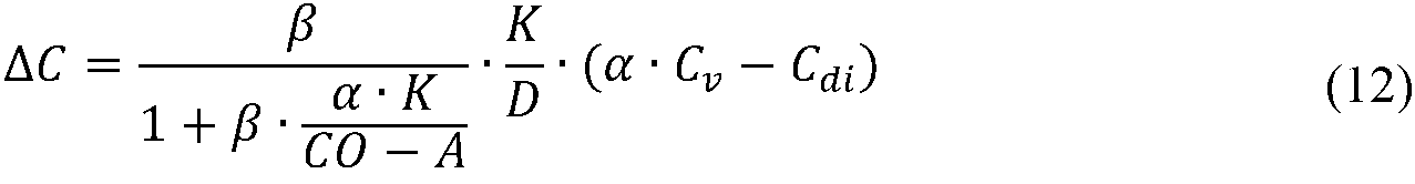
![]()
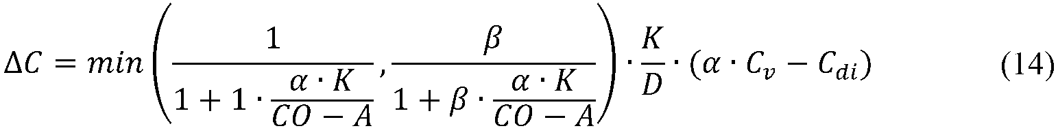
式(9)および式(12)はAの全ての値をカバーする一つの数式にまとめられてもよい:
形式的解析の第3部は図6Cに基づき、図6Cは、アクセスデバイスが逆位置にある水圧モデルにおける流体の流れを示す。 この場合、質量バランス解析は以下を与える:
![]()
![]()
式(15)、式(6)および式(8)を組み合わせることで以下が与えられる:

式(14)および式(16)の両方は以下の通りに書き直されうる:

まとめると、上述の解析は、以下の動作パラメータのそれぞれがステップ52および54中およびそれらの間に実質的に不変となるよう制御される場合において、非ボラース技術を接続テスト50に適用して使用可能であることを示す:血流量B、処理流体流量D、および透析器4へのインレットにおける処理流体の伝導性Cdi。この文脈で、「実質的に不変」は、対応する動作パラメータのわずかな変動が、その結果生じるΔCの変化がポンピング向きの切り替えにより生じる変化と比べて小さい限りにおいて許されることを意味する。典型的には、これらの動作パラメータの変動により生じる1%、±2%、±5%または±10%のΔCの変化は小さいと見なされる。例えば、血液ポンプのスピードが不変に保たれる場合であっても血液ポンプ5により生成される血流量Bはポンピング向きの間でわずかに異なりうるものであり、これはポンピング向きの切り替えがポンプのインレットにおける流体圧力を変えうるからである。もし必要であるとみなされるなら、例えばUS4468219に開示されるようなポンプの上流で測定された流体圧力に基づいてポンプのスピードを調整するもののような、周知の補償技術を実装することによって、結果として得られる血流量Bの差分を低減することができる。したがって、図3の文脈において、制御ユニット15または専用ポンプコントローラ(不図示)は、第1または第2動作状態において、EC回路1aのなかで血液ポンプ5の上流に設けられている圧力センサ(不図示)からの圧力信号に基づいて、血液ポンプ5用の制御信号C2を調整するよう構成されてもよく、この場合、制御信号C2は血液ポンプ5に、第1および第2動作状態において実質的に不変の血流量Bを維持させる。血液ポンプ5の両サイドの圧力センサからの圧力信号に基づく補償技術を適用することも想定される。
In summary, the above analysis uses a non-bolus technique applied to the
図5の接続テスト50に戻り、ステップ52はセンサ10A、10Bから対応する第1センサ値を取得することを含んでもよく、ステップ54はセンサ10A、10Bから対応する第2センサ値を取得することを含んでもよく、ステップ55は第1動作状態および第2動作状態のそれぞれについてのΔCの値を算出することを含んでもよい。第1動作状態と第2動作状態との間で生体内クリアランスを比較する目的で、ΔCの値に基づいて、パラメータB、DおよびCdiはステップ52および54中およびそれらの間で実質的に不変となるよう制御される。ステップ55で、生体内クリアランスの変化を表すべく、効率変化パラメータがΔCの関数として算出される。
Returning to the
血液ポンプの逆転の前後で伝導性差分ΔCの測定がインレット伝導性Cdiを変えることなく、したがってTF回路1bにボラースを生成することなく、なされることを注意することは重要である。インレット伝導性が患者の血漿伝導性、すなわち式(17)のCdi=α・Cν、と等しい場合、ポンピング向きの切り替えが測定される伝導性差分ΔCの変化を生じさせないことは注意されるべきである。したがって、接続テスト50を開始する前に、測定される伝導性差分ΔCが最小値を超えているかを検証することが好ましい場合がある。最小値は、接続テスト50の十分な確度を与えるよう予め定められてもよい。例えば、制御ユニット15は、B、DおよびCdiの所与の値を用いて第1または第2動作状態の機器1を動作させ、測定信号S1、S2に基づいてΔCの値を算出し、ΔCの値を最小値と比較してもよい。ΔCの値が最小値よりも小さい場合、制御ユニット15は制御信号C4を生成することによってソース6を動作させ、ΔCの値が最小値を超えるようにインレット伝導性Cdiを調整する。第1動作状態および第2動作状態の両方について算出されたΔCの値に対してこの調整がなされてもよいことも想定されている。検証は準備的手順であって、図5の接続テスト50よりも前に完了されている。次いで、接続テスト50は、B、Dの所与の値、および、検証により与えられるインレット伝導性Cdiで実行される。
It is important to note that the measurement of the conduction difference ΔC before and after the reversal of the blood pump is made without altering the inlet conductivity C di and thus without creating bolus in the
例えばTF回路1bの(例えば、制御信号C4を介した)セッティングから、インレット伝導性Cdiが制御ユニット15に知られている場合、上流のセンサ10Aを省略してもよいことは理解されるべきである。
It should be understood, for example, from the settings of the
図5のステップ56における評価は、第1動作状態の流れの向きの状態に依存して伝導性差分ΔCがどのように変化するかの理解に基づいて実現される。式(14)および式(16)に基づいて、また対向流透析器構成について式(1)から、および並流透析器構成について式(3)から取られたKを用いて、この理解はさらに説明され例示される。
The evaluation in
図7は、図3の機器1のさまざまな流れの向きの状態について、血流量Bの関数として理論的に算出されたΔCの値のプロットである。曲線70は、対向流透析器構成および通常アクセスデバイス構成(すなわち、正しい状態)について算出されたものである。曲線71は、対向流透析器構成および逆アクセスデバイス構成(すなわち、アクセス障害状態)について算出されたものである。曲線72は、並流透析器構成および通常アクセスデバイス構成(すなわち、透析器障害状態)について算出されたものである。曲線73は、並流透析器構成および逆アクセスデバイス構成(すなわち、二重障害状態)について算出されたものである。曲線70-73は、血液と処理流体との間の伝導性勾配が1mS/cmであり、CO = 5リットル/分、D = 500ml/分、k0A = 1500ml/分、A = 1000ml/分、および限外濾過なしとして計算された。
FIG. 7 is a plot of the values of ΔC theoretically calculated as a function of blood flow B for the states of various flow directions of the
図7は、異なる流れの向きの状態の間で、ΔCの値にかなりの差があることを示す。矢印77は、血流量B = 250ml/分において、正しい状態から二重障害状態へと切り替えたまたはその逆を行った際の、ΔCの値の変化を示し(図4Aおよび図4D参照)、矢印78は、アクセス障害状態から透析器障害状態へと切り替えたまたはその逆を行った際の、ΔCの値の変化を示す(図4Bおよび図4C参照)。図示の通り、変化77は変化78よりもかなり大きい。したがって、正しい状態と二重障害状態との間の切り替えと、アクセス障害状態と透析器障害状態との間の切り替えと、を区別することが可能である。さらに、曲線70-73はよく分離されているので、少なくとも血流量Bが約100ml/分かそれ以上において、変化の符号を用いることで第1および第2動作状態に流れの向きの状態を割り当てることが可能である。
FIG. 7 shows that there is a considerable difference in the value of ΔC between different flow direction states.
上述の解析を、図5のステップ55-56にしたがう効率変化パラメータの算出および評価へと公式化するための数多くの方法があることを、当業者であれば容易に認識するであろう。一例では、効率変化パラメータはステップ55においてΔCの値の(重み付け)差分として算出され、ステップ56においてそれは大きさおよび符号について解析されてもよい。他の例では、効率変化パラメータはステップ55においてΔCの値の比Rの関数として算出されるかそれによって与えられ、大きさについて解析されてもよい。
Those skilled in the art will readily recognize that there are numerous methods for formulating the above analysis into the calculation and evaluation of efficiency change parameters according to steps 55-56 of FIG. In one example, the efficiency change parameter is calculated in
図7は、特定の流れの向きの状態を第1動作状態に割り当てるように接続テストを行うことが確かに可能であり、それによりオペレータに十分なフィードバックを提供できる(ステップ57)ことを示しているが、関連数式に含まれる異なる制御パラメータの全ての値についてこの割り当てが可能であるかは、判定されるべきものとして残る。制御パラメータは、制御ユニット15によって知られ、制御ユニット15によって設定されてもよい動作パラメータと、制御ユニット15によって変更不可なシステムパラメータと、の両方を含む。動作パラメータは、血流量Bと、処理流体流量Dと、である。システムパラメータは、膜浸透度k0Aと、アクセス流量Aと、心臓出力COと、である。膜浸透度k0Aは、例えば組み付けられた透析器4についての情報が機器1に供給されるか機器1によって取得された場合、制御ユニット15によって知られていてもよい。しかしながら、アクセス流量Aおよび心臓出力CO は、通常、制御ユニット15には知られていない。それらは患者に特定のものであって経時的に変化するものであるからである。したがって、接続テストは、少なくともアクセス流量Aおよび心臓出力COに依存しないことが好ましい。
FIG. 7 shows that it is certainly possible to perform a connection test to assign a particular flow direction state to the first operating state, thereby providing sufficient feedback to the operator (step 57). However, it remains to be determined whether this assignment is possible for all the values of the different control parameters contained in the relevant formula. The control parameters include both operating parameters known by the
図8A-8Bに提示されるシミュレーション結果を参照して、接続テストの限界をさらに調べる。シミュレーションは上述の式(1)、(3)、(14)および(16)に基づくものであった。図8Aは、CO = 6リットル/分で計算された多数のグラフの集合であって、水平方向にはDが増大するように(300ml/分、400ml/分、500ml/分および800ml/分)、垂直方向にはk0Aが増大するように(600ml/分、1000ml/分および1500ml/分)、配置構成されている。個々別々のグラフは、五つの異なるアクセス流量A(200ml/分、400ml/分、500ml/分、1000ml/分および1500ml/分)について、血流量Bの関数として算出されたΔCの値(切り替えの前後)の比Rの曲線を示す。比Rは三つの異なる切り替えについて算出される:正しい状態から二重障害状態へ(実線)、透析器障害状態からアクセス障害状態へ(破線)、およびアクセス障害状態から透析器障害状態へ(破線)。図8Bは、CO = 2.5リットル/分で計算されたグラフの対応する集合である。 The limitations of the connection test are further investigated with reference to the simulation results presented in FIGS. 8A-8B. The simulation was based on the above equations (1), (3), (14) and (16). FIG. 8A is a collection of a large number of graphs calculated at CO = 6 liters / minute with D increasing horizontally (300 ml / min, 400 ml / min, 500 ml / min and 800 ml / min). , It is arranged so that k 0 A increases in the vertical direction (600 ml / min, 1000 ml / min and 1500 ml / min). The individual graphs show the values of ΔC (switching) calculated as a function of blood flow B for five different access flow rates A (200 ml / min, 400 ml / min, 500 ml / min, 1000 ml / min and 1500 ml / min). The curve of the ratio R (before and after) is shown. The ratio R is calculated for three different switches: from correct state to double failure state (solid line), from dialyzer failure state to access failure state (dashed line), and from access failure state to dialyzer failure state (dashed line). .. FIG. 8B is the corresponding set of graphs calculated at CO = 2.5 liters / minute.
図8A-8Bのグラフは、A、COおよびk0Aによらず、正しい状態と二重障害状態とを区別できることを示している。正しい状態から二重障害状態への切り替えの際の比R(実線)は常に一(1)よりも大きいからである。正しい状態(または等価で二重障害状態)と単一障害状態(破線)とを区別するためには、アクセス流量Aおよび心臓出力COの全ての値についてのグラフにおいて実線曲線と破線曲線との間に明確な分離がなければならない。図8A-8Bに示されるように、高い処理流体流量D、低い血流量Bおよび小さい膜浸透度k0Aについて、破線曲線と実線曲線との間に重なりができる傾向が増大する。逆に、これは、処理流体流量Dおよび血流量Bを適切に選択することによって、実線曲線と破線曲線との明確な分離を確実にできることを意味する。図8A-8Bは、処理流体流量Dが最小化されるべきであることを示す。 D = 800ml/分において、実線曲線と破線曲線との間に顕著な重なりがあり、これは特にCO = 2.5リットル/分のときD = 500ml/分でも部分的に残る。一例では、処理流体流量Dは、重なりを最小化するために200-400ml/分の範囲に設定されてもよい。血流量Bは低すぎても高すぎてもいけない。低いBでは、アクセス流量Aが低すぎて再循環のリスクがある場合に分離が小さくなろう。これは、血流量Bが患者の大部分のアクセス流量Aを超えつつも、破線曲線と実線曲線との間の十分な分離を生じさせるように設定されなければならないことを意味する。一例では、血流量B は、200-300ml/分の範囲に設定されてもよい。 The graphs in FIGS. 8A-8B show that the correct state and the double fault state can be distinguished regardless of A, CO and k 0 A. This is because the ratio R (solid line) at the time of switching from the correct state to the double failure state is always larger than one (1). To distinguish between the correct state (or equivalent and double failure state) and the single failure state (dashed line), between the solid and dashed curves in the graph for all values of access flow rate A and cardiac output CO. There must be a clear separation. As shown in FIGS. 8A-8B, for high processing fluid flow rate D, low blood flow rate B and small membrane permeability k 0 A, there is an increased tendency for overlap between the dashed curve and the solid curve. On the contrary, this means that proper selection of the processing fluid flow rate D and blood flow rate B ensures a clear separation between the solid line curve and the dashed line curve. 8A-8B show that the processing fluid flow rate D should be minimized. At D = 800 ml / min, there is a marked overlap between the solid and dashed curves, which remains partially even at D = 500 ml / min, especially when CO = 2.5 liters / min. In one example, the processing fluid flow rate D may be set in the range of 200-400 ml / min to minimize overlap. Blood flow B should not be too low or too high. At low B, the separation will be small if the access flow rate A is too low and there is a risk of recirculation. This means that blood flow B must be set to exceed most of the patient's access flow rate A, but still provide sufficient separation between the dashed and solid curves. In one example, blood flow B may be set in the range of 200-300 ml / min.
したがって、制御ユニット15は、図5のステップ51の前に、接続テスト50専用のセッティングを取得し、専用セッティングに基づいて機器1を第1および第2動作状態に設定するよう構成されてもよい。セッティングはメモリ18に保持されてもよく、接続テスト50中に適用されるべきBおよびDのセット値を含んでもよい。セッティングはまた、処理流体のインレット伝導性Cdiのセット値を含んでもよい。
Therefore, the
図9A-9Bは上述の式(1)、(3)、(14)および(16)に基づいて生成されたさらなるシミュレーション結果を示し、これはステップ56の評価をさらに例示する役に立つであろう。図9Aは、七つの異なるアクセス流量A(200ml/分、300ml/分、400ml/分、500ml/分、1000ml/分、1500ml/分および2000ml/分)について、B = 200ml/分、D = 300ml/分およびCO = 6リットル/分において、膜浸透度k0Aの関数として計算されたΔCの値(切り替えの前後)の比Rのプロットである。実線曲線は正しい状態から二重障害状態への切り替えを表し、破線曲線は単一障害状態間(透析器障害状態からアクセス障害状態へ、またはその逆)の切り替えを表す。図9Bは、CO = 2.5リットル/分で計算された対応するプロットである。プロットはR≧1について与えられ、これは所定の破線曲線が示されていないことを意味することは注意されるべきである。図9Bの二つの最も下の実線曲線はアクセス流量が1500ml/分および2000ml/分に対応し、これらは2.5リットル/分の心臓出力では生じる蓋然性が低いことも注意されるべきである。したがって、図9Bの二つの下側の実線曲線は、生理学上の理由により以下の解析から除かれる。
FIGS. 9A-9B show further simulation results generated based on the above equations (1), (3), (14) and (16), which would be useful to further illustrate the evaluation of
図9A-9Bから分かる通り、組み付けられた透析器4の膜浸透度k0Aが知られると、膜浸透度k0Aのほぼ全ての値について、実線曲線と破線曲線とが分離される。したがって、異なる切り替えを区別するリミットを、膜浸透度k0Aの関数として設定することができる。図9A-9Bはまた、組み付けられた透析器4の膜浸透度k0Aが分からない場合でも、異なる切り替えを区別することができることを示す。これは、本例ではR=1.35であるところの第1リミットL1を設定することであって、この第1リミットL1より下では第1動作状態に接続エラー(すなわち、単一障害状態または二重障害状態)が確かに存在するものである、設定することと、本例ではR=1.5であるところの第2リミットL2を設定することであって、この第2リミットL2より上では第1動作状態が正しい状態にあることが確実である、設定することと、によって達成可能である。したがって、ステップ56では、制御ユニット15はステップ55で算出されたRの値をリミットL1、L2と比較し、Rの値がL1より下となる場合には接続エラーを、Rの値がL2より上となる場合には正しい状態を、またはRの値がリミットL1、L2の間にあるなら潜在的障害状態を、特定してもよい。しかしながら、潜在的障害状態は、非常に小さな膜浸透度k0Aを伴う透析器4についてのみ生じうることは注意されるべきである。ある実装では、制御ユニット15は、組み付けられた透析器4の膜浸透度k0Aを示すデータ、例えばモデル番号等、を入力するようオペレータに要求することによって、潜在的障害状態の解決を試行する。入力されたデータに基づいて、制御ユニット15は、図9A-9Bにしたがい膜浸透度k0Aに対して調整された新たなリミットを取得し、R値の第2の評価に新たなリミットを適用してもよい。
As can be seen from FIGS. 9A-9B, when the membrane permeability k 0 A of the assembled
図10A-10Cは上述の議論をまとめることを意図したものであり、ステップ55で算出されたRの値を評価する際に図5のステップ56で制御ユニット15によって適用されてもよい異なる範囲の組み合わせを示す。各範囲は、第1動作状態における機器1の対応する流れの向きの状態に関連付けられる。したがって、ステップ56で、制御ユニット15は単にRの値を異なる範囲と比較することによって、第1動作状態の流れの向きの状態を決定してもよい。範囲は、ステップ56での取得用にメモリ18(図3)に保持されている範囲定義によって制御ユニット15に対して特定されてもよい。範囲定義は、上限値および下限値によって対応する範囲を特定してもよい。また、例えば範囲が開区間である場合には、上限値または下限値のいずれか一方によってひとつ以上の範囲を定義することも可能である。したがって、本明細書で用いられる場合、「範囲」は閉区間範囲および開区間範囲の両方を含む。実装に依存して、動作パラメータおよび/またはシステムパラメータの異なる組み合わせに対して範囲定義が与えられてもよい。そのような範囲定義は、ひとつ以上のルックアップテーブルによって、および/または、動作パラメータおよび/またはシステムパラメータのひとつ以上の現在値に基づいて対応する範囲を算出するひとつ以上の機能によって、実現されてもよい。したがって、ステップ56において、制御ユニット15は、動作パラメータおよび/またはシステムパラメータの現在値に基づいて範囲定義にアクセスすることによって、動的に範囲を取得してもよい。
10A-10C are intended to summarize the above discussion and may be applied by the
図10Aは、上述のシステムパラメータ(A、CO、k0A)によらずに適用可能となるよう設定された範囲ΔR1-ΔR3を示し、ここでは、ΔR1が正しい状態に対応し、ΔR2が二重障害状態に対応し、ΔR3が単一障害状態に対応する。上述の議論から理解される通り、図10Aの定義は、機器1が血流量Bおよび/または処理流体流量Dの所定の間隔内で動作する場合にのみ正しいものとなろう。定義はさらにBおよびDの値の特定の組み合わせに制限されうる。ひとつ以上のシステムパラメータが知られている場合でも、ステップ56においてΔR1-ΔR3の対応する定義を使用可能であることは理解されるべきである。
FIG. 10A shows the range ΔR1-ΔR3 set to be applicable regardless of the system parameters (A, CO, k 0 A) described above, where ΔR1 corresponds to the correct state and ΔR2 is two. Corresponds to a serious failure state and ΔR3 corresponds to a single failure state. As understood from the discussion above, the definition of FIG. 10A will only be correct if
図10Bは図10Aの定義の変形例を示し、そこではΔR3の両側に追加的な範囲ΔR4'、ΔR4"をそれぞれΔR2およびΔR1に隣接するように定義する。範囲ΔR4'、ΔR4"は両方とも上述の潜在的障害状態(図9A-9B参照)に関連付けられる。 FIG. 10B shows a modification of the definition of FIG. 10A, where additional ranges ΔR4'and ΔR4'are defined adjacent to ΔR2 and ΔR1 respectively on both sides of ΔR3, where the ranges ΔR4' and ΔR4' are both adjacent. Associated with the potential failure conditions described above (see FIGS. 9A-9B).
図10Cは、第1動作状態の全ての可能な流れの向きの状態を特定することが可能な範囲定義を示し、そこでは、範囲ΔR1が正しい状態に対応し、ΔR2が二重障害状態に対応し、ΔR3'がアクセス障害状態に対応し、ΔR3"が透析器障害状態に対応する。図10Cの範囲定義は、典型的には動作パラメータおよびシステムパラメータのうちの少なくともいくつかの特定値または制限された間隔の特定の組み合わせについて正しい。例えば、範囲は、図10Cに示されるように、B、D、k0AおよびAの値/範囲の特定の組み合わせについてのみ正しいものとなるように、図7に基づいて定義されてもよい。 FIG. 10C shows a range definition capable of specifying all possible flow orientation states of the first operating state, where range ΔR1 corresponds to the correct state and ΔR2 corresponds to the double fault state. And ΔR3'corresponds to an access failure condition and ΔR3' corresponds to a dialyzer failure condition. The range definition of FIG. 10C typically corresponds to at least some specific value or limitation of operating parameters and system parameters. Correct for a particular combination of intervals, eg, the range is correct only for a particular combination of values / ranges of B, D, k 0 A and A, as shown in FIG. 10C. It may be defined based on 7.
図10A-10Cはまた、背景セクションで議論されたWO2012/016671により提案される検出技術ではアクセスデバイス2'、2''における接続エラーを検出できないことを示す。なぜならば、それはクリアランスパラメータの比を1と比較することだけを行うよう構成されているからである。本開示の用語において、WO2012/016671の技術は正しい状態(R>1)と透析器障害状態(R<1)とを区別するためだけに設計されている一方、本発明の実施の形態は、二重障害状態(例えば、ΔR2による)や単一障害状態(例えば、ΔR3による)やアクセス障害状態(例えば、ΔR3'による)や潜在的障害状態(例えば、ΔR4'、ΔR4"による)などの追加的な障害状態を検出するよう調整されている。 FIGS. 10A-10C also show that the detection techniques proposed by WO2012 / 016671 discussed in the background section cannot detect connection errors in access devices 2'and 2''. This is because it is configured to only compare the ratio of clearance parameters to one. In the terms of the present disclosure, the technique of WO2012 / 016671 is designed solely to distinguish between the correct state (R> 1) and the dialyzer failure state (R <1), while embodiments of the present invention are: Addition of double failure states (eg, due to ΔR2), single failure states (eg, due to ΔR3), access failure states (eg, due to ΔR3'), potential failure states (eg, due to ΔR4', ΔR4'), etc. It is tuned to detect typical failure conditions.
本明細書で説明される制御ユニット15はひとつ以上の汎用計算デバイスまたは専用計算デバイスで実行される専用ソフトウエア(またはファームウエア)によって実装されてもよい。この文脈で、そのような計算デバイスの「要素」や「手段」が方法ステップの概念的等価物を指すことは理解されるべきであり、要素/手段とハードウエアやソフトウエアルーチンの特定のピースとの間に必ずしも1対1の関係があるわけではない。ある場合、ハードウエアのひとつのピースは異なる手段/要素を含む。例えば、プロセッサはひとつのインストラクションを実行する場合にはひとつの要素/手段としての役割を果たすが、他のインストラクションを実行する場合には他の要素/手段としての役割を果たす。加えて、ひとつの要素/手段はある場合にはひとつのインストラクションによって実装されうるが、他の場合には複数のインストラクションによって実装されうる。そのようなソフトウエア制御計算デバイスは、例えばCPU(「Central Processing Unit」)やDSP(「Digital Signal Processor」)やASIC(「Application-Specific Integrated Circuit」)などのひとつ以上のプロセッサ(図3の17参照)や、ディスクリートアナログコンポーネントおよび/またはデジタルコンポーネントや、FPGA(「Field Programmable Gate Array」)などの他のプログラム可能論理デバイスを含んでもよい。制御ユニット15はさらに、システムメモリと、システムメモリ(図3の18参照)を含む種々のシステムコンポーネントをプロセッサに繋ぐシステムバスと、を含んでもよい。システムバスは、メモリバスまたはメモリコントローラ、周辺バス、および種々のバスアーキテクチャのいずれかを用いるローカルバスを含むいくつかのタイプのバス構成のいずれかであってもよい。システムメモリは、読み出し専用メモリ(ROM)やランダムアクセスメモリ(RAM)やフラッシュメモリなどの揮発性および/または不揮発性メモリの形態のコンピュータストレージ媒体を含んでもよい。専用ソフトウエアはシステムメモリに保持されてもよく、または磁気媒体や光学媒体やフラッシュメモリカードやデジタルテープやソリッドステートRAMやソリッドステートROMなどの、計算デバイスに含まれるかそれからアクセス可能な他の取り外し可能/取り外し不可の揮発性/不揮発性コンピュータストレージ媒体に保持されてもよい。制御ユニット15は、シリアルインタフェースやパラレルインタフェースやUSBインタフェースや無線インタフェースやネットワークアダプタなどのひとつ以上の通信インタフェースと、A/Dコンバータなどのひとつ以上のデータ取得デバイスと、を含んでもよい。専用ソフトウエアは、記録媒体や読み出し専用メモリを含む任意の適切な一時的または非一時的コンピュータ可読媒体上で制御ユニット15に提供されてもよい。また、従来からよく知られているように、いくつか(または全て)の要素/手段は全体的にまたは部分的に、FPGAやASICやディスクリート電子コンポーネント(レジスタ、キャパシタ、オペアンプ、トランジスタ、フィルタ等)などの専用ハードウエアによって実装されてもよいことも想定されている。本発明はデジタル信号処理に限定されるものではなく、アナログデバイスの組み合わせにより完全に実装可能であることは強調されるべきである。
The
最も実際的で好適な実施の形態であると現時点で考えられているものとの関係で本発明が説明されたが、本発明は開示された実施の形態に限定されるものではなく、むしろ添付の請求項の範囲に含まれる種々の変形例および等価な構成をカバーするよう意図されていることは理解されるべきである。 Although the invention has been described in relation to what is currently considered to be the most practical and preferred embodiment, the invention is not limited to the disclosed embodiments, but rather by attachment. It should be understood that it is intended to cover the various variants and equivalent configurations contained within the scope of the claims.
例えば、図10A-10Cに関連して説明された比Rの解析は、上述のボラース技術により得られる効率値の比にも等しく適用可能である。さらに、上述の説明は、当業者が、例えば第1動作状態および第2動作状態について算出された効率値の間の差分などの、比R以外の他の評価変化パラメータに基づく接続テストを、ボラース技術または非ボラース技術のいずれかに基づいて、設計することを容易に可能とする。 For example, the analysis of ratio R described in connection with FIGS. 10A-10C is equally applicable to the ratio of efficiency values obtained by the above-mentioned volus technique. Further, the above description will allow one of ordinary skill in the art to perform a connection test based on other evaluation change parameters other than the ratio R, such as the difference between the efficiency values calculated for the first and second operating states. It makes it easy to design based on either technical or non-volatile technology.
さらに、機器1が、制御信号C3による代わりに人手により、第1動作状態と第2動作状態との間で切り替えられることも想定されている。例えば、制御ユニット15は、ステップ53の前にUIデバイス16を介して、オペレータに、血液ポンプ5の逆転を手動で実行するよう指示してもよい。
Further, it is also assumed that the
上述の実施の形態は制御ユニット15に、制御信号C4によって処理流体の測定された特性を設定する能力を付与しているが、接続テスト40はまた、例えばソース6が所定の組成の既製の処理流体を供給するよう構成される場合など、この能力を欠く実施の形態についても実装可能である。
While the embodiments described above confer on the
Claims (24)
前記血液ポンプ(5)が前記第1アクセスデバイス(2’;2’’)から前記透析器(4)の前記血液コンパートメント(4A)を通じて前記第2アクセスデバイス(2’’;2’)へと前記血液をポンプするためにデフォルト向きで動作する第1動作状態と、前記血液ポンプ(5)が前記第2アクセスデバイス(2’’;2’)から前記透析器の前記血液コンパートメント(4B)を通じて前記第1アクセスデバイス(2’;2’’)へと前記流体をポンプするために逆向きで動作する第2動作状態と、の間で、前記血液処理機器(1)を切り替えさせることと、
前記血液処理機器(1)内の少なくともひとつのセンサ(10A、10B)の出力信号(S1、S2)を取得することと、
前記第1動作状態と前記第2動作状態との間の前記血液処理機器(1)の前記切り替え中の前記血液処理機器(1)の生体内クリアランスの変化を表す効率変化パラメータを、前記出力信号(S1、S2)に基づいて、算出することと、
前記効率変化パラメータを評価することによって、前記第1動作状態または前記第2動作状態が二重障害状態を含むか否かを判定することであって、前記二重障害状態が並流透析器構成と逆アクセスデバイス構成との両方を含み、前記並流透析器構成では前記血液コンパートメント(4A)を通じた血液の前記流れと前記処理流体コンパートメント(4B)を通じた処理流体の前記流れとが前記半透膜(4’)に沿った共通の向きにあり、前記逆アクセスデバイス構成では前記第1および第2アクセスデバイス(2’、2’’)がそれぞれ前記血管アクセス(3)の前記下流部および前記上流部に接続されている、判定することと、を行うよう構成される制御デバイス。 A control device for the blood processing apparatus (1), wherein the blood processing apparatus (1) includes an extracorporeal blood flow circuit (1a) and a processing fluid flow circuit (1b), and the extracorporeal blood flow circuit (1a) is a patient. 1st in the extracorporeal blood flow circuit (1a), with first and second access devices (2'2'') for connecting to the upstream and downstream parts of the vascular access (3), respectively. And the other of the first and second access devices (2', 2'') from one of the second access devices (2', 2'') through the blood compartment (4A) of the dialyzer (4). It has a blood pump (5) that can operate to generate a blood flow to and from the processing fluid flow circuit (1b) through the processing fluid compartment (4B) of the dialyzer (4). Configured to produce, the treated fluid compartment (4B) is separated from the blood compartment by a translucent membrane (4'), and the control device is connected during a connection test.
The blood pump (5) travels from the first access device (2';2'') to the second access device (2'';2') through the blood compartment (4A) of the dialyzer (4). A first operating state operating in the default orientation to pump the blood, and the blood pump (5) from the second access device (2'';2') through the blood compartment (4B) of the dialyzer. Switching the blood processing device (1) between a second operating state, which operates in the opposite direction to pump the fluid to the first access device (2';2''), and
Acquiring the output signals (S1, S2) of at least one sensor (10A, 10B) in the blood processing device (1),
The output signal indicates an efficiency change parameter representing a change in the in vivo clearance of the blood processing device (1) during the switching of the blood processing device (1) between the first operating state and the second operating state. To calculate based on (S1, S2) and
By evaluating the efficiency change parameter, it is determined whether or not the first operating state or the second operating state includes a double failure state, and the double failure state includes a parallel flow dialyzer configuration. In the parallel dialysis machine configuration, the flow of blood through the blood compartment (4A) and the flow of processing fluid through the processing fluid compartment (4B) are semipermeable. They are in a common orientation along the membrane (4'), and in the reverse access device configuration, the first and second access devices (2', 2'') are the downstream portion of the vascular access (3) and the said, respectively. A control device that is connected to the upstream and is configured to determine and perform.
前記第1動作状態が前記二重障害状態を含むと判定された場合、前記処理流体流回路(1b)または前記体外血流回路(1a)の前記透析器(4)への接続を変更するよう、かつ、前記第1および第2アクセスデバイス(2’、2’’)の前記血管アクセス(3)への接続を変更するよう、前記オペレータに指示するよう前記インタフェースデバイス(16)を動作させるように前記制御デバイスが構成される請求項1または2に記載の制御デバイス。 The control device is operably associated with the interface device (16), and the interface device (16) is configured to output instructions for the operator of the blood processing device (1).
When it is determined that the first operating state includes the double fault state, the connection of the processing fluid flow circuit (1b) or the extracorporeal blood flow circuit (1a) to the dialyzer (4) is changed. And to operate the interface device (16) to instruct the operator to change the connection of the first and second access devices (2'2'') to the blood vessel access (3). The control device according to claim 1 or 2, wherein the control device is configured.
前記制御デバイスはさらに、前記効率変化パラメータが前記第4範囲または前記第5範囲内に入る場合、前記透析器(4)の物質移送エリア係数を示すよう前記血液処理機器(1)のオペレータに指示するよう構成される請求項10に記載の制御デバイス。 A fourth range (ΔR4') is defined between the first and third ranges (ΔR1, ΔR3), and a fifth range (ΔR4'') is between the second and third ranges (ΔR2, ΔR3). Defined
The control device further instructs the operator of the blood treatment apparatus (1) to indicate the mass transfer area factor of the dialyzer (4) when the efficiency change parameter falls within the fourth range or the fifth range. 10. The control device of claim 10.
前記血液ポンプ(5)が前記第1アクセスデバイス(2’;2’’)から前記透析器(4)の前記血液コンパートメント(4A)を通じて前記第2アクセスデバイス(2’’;2’)へと前記血液をポンプするためにデフォルト向きで動作する第1動作状態と、前記血液ポンプ(5)が前記第2アクセスデバイス(2’’;2’)から前記透析器(4)の前記血液コンパートメント(4A)を通じて前記第1アクセスデバイス(2’;2’’)へと前記流体をポンプするために逆向きで動作する第2動作状態と、の間で、前記血液処理機器(1)が切り替えられるよう構成されており、前記作動方法が、
前記第1動作状態と前記第2動作状態との間で切り替えられたときの前記血液処理機器(1)の生体内クリアランスの変化を表す効率変化パラメータを、前記制御デバイスが、前記血液処理機器(1)内の少なくともひとつのセンサ(10A、10B)の出力信号に基づいて、算出することと、
前記効率変化パラメータを評価することによって、前記制御デバイスが、前記第1動作状態または前記第2動作状態が二重障害状態を含むか否かを判定することであって、前記二重障害状態が並流透析器構成と逆アクセスデバイス構成との両方を含み、前記並流透析器構成では前記血液コンパートメント(4A)を通じた血液の前記流れと前記処理流体コンパートメント(4B)を通じた処理流体の前記流れとが前記半透膜(4’)に沿った共通の向きにあり、前記逆アクセスデバイス構成では前記第1および第2アクセスデバイス(2’、2’’)がそれぞれ前記血管アクセス(3)の前記下流部および前記上流部に接続されている、判定することと、を含む作動方法。 A method of operating a blood processing device (1) including a control device (15) , wherein the blood processing device (1) includes an extracorporeal blood flow circuit (1a) and a processing fluid flow circuit (1b), and the extracorporeal blood. The extracorporeal blood flow circuit (1a) is accompanied by a first and second access device (2', 2'') for connecting the flow circuit (1a) to the upstream and downstream parts of the patient's vascular access (3). ) From one of the first and second access devices (2', 2'') through the blood compartment (4A) of the dialyzer (4), the first and second access devices (2', 2''). ) Has a blood pump (5) capable of operating to generate a blood flow to the other of the), the processing fluid flow circuit (1b) through the processing fluid compartment (4B) of the dialyzer (4). The treated fluid compartment (4B) is separated from the blood compartment by a semi-permeable membrane (4'), configured to generate a flow of treated fluid.
The blood pump (5) travels from the first access device (2';2'') to the second access device (2'';2') through the blood compartment (4A) of the dialyzer (4). A first operating state in which the blood pump (5) operates in the default orientation to pump the blood and the blood compartment of the dialyzer (4) from the second access device (2'';2'). The blood processing apparatus (1) is switched between a second operating state, which operates in the opposite direction to pump the fluid to the first access device (2';2'') through 4A). The operation method is as follows.
The control device controls the blood processing device (1) to set an efficiency change parameter representing a change in the in-vivo clearance of the blood processing device (1) when the first operating state and the second operating state are switched. Calculation based on the output signal of at least one sensor (10A, 10B) in 1)
By evaluating the efficiency change parameter, the control device determines whether or not the first operating state or the second operating state includes a double failure state, wherein the double failure state is determined. The parallel flow dialyzer configuration includes both a parallel flow dialyzer configuration and a reverse access device configuration, the flow of blood through the blood compartment (4A) and the flow of treatment fluid through the processing fluid compartment (4B) in the parallel flow dialyzer configuration. And are in a common orientation along the semipermeable membrane (4'), and in the reverse access device configuration, the first and second access devices (2', 2'') are of the blood vessel access (3), respectively. An operating method comprising determining that the downstream portion and the upstream portion are connected.
Applications Claiming Priority (3)
| Application Number | Priority Date | Filing Date | Title |
|---|---|---|---|
| SE1650950 | 2016-06-30 | ||
| SE1650950-7 | 2016-06-30 | ||
| PCT/EP2017/065770 WO2018001996A1 (en) | 2016-06-30 | 2017-06-27 | Connection test for blood treatment machines ii |
Publications (2)
| Publication Number | Publication Date |
|---|---|
| JP2019519263A JP2019519263A (en) | 2019-07-11 |
| JP6991155B2 true JP6991155B2 (en) | 2022-01-12 |
Family
ID=59239908
Family Applications (1)
| Application Number | Title | Priority Date | Filing Date |
|---|---|---|---|
| JP2018555740A Active JP6991155B2 (en) | 2016-06-30 | 2017-06-27 | Connection test of blood processing device II |
Country Status (5)
| Country | Link |
|---|---|
| US (1) | US11433167B2 (en) |
| EP (1) | EP3478334B1 (en) |
| JP (1) | JP6991155B2 (en) |
| CN (1) | CN109475672B (en) |
| WO (1) | WO2018001996A1 (en) |
Families Citing this family (6)
| Publication number | Priority date | Publication date | Assignee | Title |
|---|---|---|---|---|
| DE102017005534A1 (en) | 2017-06-10 | 2018-12-13 | Fresenius Medical Care Deutschland Gmbh | Apparatus for extracorporeal blood treatment and method for determining a hemodynamic parameter during extracorporeal blood treatment |
| DE102017005535A1 (en) * | 2017-06-10 | 2018-12-13 | Fresenius Medical Care Deutschland Gmbh | Apparatus for extracorporeal blood treatment and apparatus for collecting blood clots and method for determining a hemodynamic parameter during extracorporeal blood treatment |
| JP7061509B2 (en) * | 2018-04-26 | 2022-04-28 | 日機装株式会社 | Blood purification device |
| WO2020154638A1 (en) * | 2019-01-25 | 2020-07-30 | Transonic Systems, Inc. | Method and apparatus for assessing cardiac output in veno-venous extracorporeal blood oxygenation |
| US11633525B2 (en) | 2019-01-29 | 2023-04-25 | Transonic Systems Inc. | Method and apparatus for assessing cardiac output in veno-arterial extracorporeal blood oxygenation |
| US11654218B2 (en) | 2019-05-02 | 2023-05-23 | Transonic Systems Inc. | Calculating cardiac output of a patient undergoing veno-venous extracorporeal blood oxygenation |
Citations (5)
| Publication number | Priority date | Publication date | Assignee | Title |
|---|---|---|---|---|
| JP2005516688A (en) | 2002-02-08 | 2005-06-09 | ガンブロ・ルンディア・エービー | Method and apparatus for determining access flow |
| JP2011161060A (en) | 2010-02-10 | 2011-08-25 | Nikkiso Co Ltd | Blood purifier |
| JP2013523361A (en) | 2010-04-14 | 2013-06-17 | フレセニウス・メディカル・ケア・ドイチュラント・ゲーエムベーハー | Apparatus and method for monitoring the connection of a blood treatment unit to a fluid system of an extracorporeal blood treatment apparatus |
| JP2014519898A (en) | 2011-05-23 | 2014-08-21 | フレゼニウス メディカル ケア ドイッチェランド ゲゼルシャフト ミット ベシュレンクテル ハフツング | Device and method for detecting operating state of extracorporeal blood treatment |
| WO2016016039A1 (en) | 2014-08-01 | 2016-02-04 | Fresenius Medical Care Deutschland Gmbh | Device for identifying the direction of liquid flow through a dialyser |
Family Cites Families (14)
| Publication number | Priority date | Publication date | Assignee | Title |
|---|---|---|---|---|
| US4468219A (en) | 1983-12-20 | 1984-08-28 | International Business Machines Corporation | Pump flow rate compensation system |
| SE465404B (en) | 1988-03-03 | 1991-09-09 | Gambro Ab | DIALYSIS SYSTEM |
| DE3938662A1 (en) | 1989-11-21 | 1991-07-18 | Fresenius Ag | METHOD FOR IN VIVO DETERMINING PARAMETERS OF HAEMODIALYSIS |
| FR2713937B1 (en) | 1993-12-17 | 1996-05-31 | Hospal Ind | Method for determining a significant parameter of the progress of an extracorporeal blood treatment. |
| US6702774B1 (en) | 1997-10-27 | 2004-03-09 | Fresenius Medical Care Deutschland Gmbh | Method of measuring dialysis or clearance of hemodialysis systems |
| US6726647B1 (en) | 1998-10-23 | 2004-04-27 | Gambro Ab | Method and device for measuring access flow |
| US6585675B1 (en) * | 2000-11-02 | 2003-07-01 | Chf Solutions, Inc. | Method and apparatus for blood withdrawal and infusion using a pressure controller |
| US7488447B2 (en) * | 2002-10-30 | 2009-02-10 | Gambro Lundia Ab | Method and an apparatus for determining the efficiency of dialysis |
| US8133194B2 (en) * | 2006-02-22 | 2012-03-13 | Henry Ford Health System | System and method for delivery of regional citrate anticoagulation to extracorporeal blood circuits |
| US20140199193A1 (en) * | 2007-02-27 | 2014-07-17 | Deka Products Limited Partnership | Blood treatment systems and methods |
| DE102008050849A1 (en) | 2008-10-08 | 2010-04-15 | Fresenius Medical Care Deutschland Gmbh | Apparatus for reversing blood flow to an extracorporeal blood treatment device and method for detecting reversal of blood flow in extracorporeal blood treatment |
| AU2010338284B2 (en) | 2009-12-28 | 2014-07-24 | Gambro Lundia Ab | Method and device for detecting a configuration of withdrawal and return devices |
| DE102010032980A1 (en) | 2010-07-31 | 2012-02-02 | Fresenius Medical Care Deutschland Gmbh | Apparatus and method for detecting the direction of fluid flow through a dialyzer |
| DE102014102731A1 (en) * | 2014-02-28 | 2015-09-03 | B. Braun Avitum Ag | Apparatus and method for detecting a venous needle disconnection |
-
2017
- 2017-06-27 JP JP2018555740A patent/JP6991155B2/en active Active
- 2017-06-27 WO PCT/EP2017/065770 patent/WO2018001996A1/en not_active Ceased
- 2017-06-27 EP EP17733808.4A patent/EP3478334B1/en active Active
- 2017-06-27 US US16/307,093 patent/US11433167B2/en active Active
- 2017-06-27 CN CN201780041373.5A patent/CN109475672B/en active Active
Patent Citations (5)
| Publication number | Priority date | Publication date | Assignee | Title |
|---|---|---|---|---|
| JP2005516688A (en) | 2002-02-08 | 2005-06-09 | ガンブロ・ルンディア・エービー | Method and apparatus for determining access flow |
| JP2011161060A (en) | 2010-02-10 | 2011-08-25 | Nikkiso Co Ltd | Blood purifier |
| JP2013523361A (en) | 2010-04-14 | 2013-06-17 | フレセニウス・メディカル・ケア・ドイチュラント・ゲーエムベーハー | Apparatus and method for monitoring the connection of a blood treatment unit to a fluid system of an extracorporeal blood treatment apparatus |
| JP2014519898A (en) | 2011-05-23 | 2014-08-21 | フレゼニウス メディカル ケア ドイッチェランド ゲゼルシャフト ミット ベシュレンクテル ハフツング | Device and method for detecting operating state of extracorporeal blood treatment |
| WO2016016039A1 (en) | 2014-08-01 | 2016-02-04 | Fresenius Medical Care Deutschland Gmbh | Device for identifying the direction of liquid flow through a dialyser |
Also Published As
| Publication number | Publication date |
|---|---|
| CN109475672B (en) | 2021-03-09 |
| JP2019519263A (en) | 2019-07-11 |
| EP3478334B1 (en) | 2020-03-25 |
| WO2018001996A1 (en) | 2018-01-04 |
| US11433167B2 (en) | 2022-09-06 |
| US20200306437A1 (en) | 2020-10-01 |
| EP3478334A1 (en) | 2019-05-08 |
| CN109475672A (en) | 2019-03-15 |
Similar Documents
| Publication | Publication Date | Title |
|---|---|---|
| JP6991155B2 (en) | Connection test of blood processing device II | |
| CA2797616C (en) | Medical apparatus for extracorporeal blood treatment and method for determining a blood parameter value in a medical apparatus | |
| CA2895171C (en) | An apparatus for extracorporeal blood treatment. | |
| KR102220982B1 (en) | Device and method for detecting the recirculation during an extracorporeal blood treatment | |
| US8858486B2 (en) | Method and arrangement for determining the recirculation in a fistula or the cardiopulmonary recirculation, and a blood treatment device comprising a device for determining the fistula recirculation or the cardiopulmonary recirculation part | |
| EP1938847B1 (en) | Apparatus for determining access flow | |
| US20240267473A1 (en) | Measuring access flow rate by use of blood treatment machine | |
| JP7470489B2 (en) | Apparatus and method for performing isotonic natremia dialysis - Patents.com | |
| US9119922B2 (en) | Apparatus and method for identifying a tubing system for an extracorporeal blood treatment device | |
| Ross et al. | Interventions to improve hemodialysis adequacy: protocols based on real-time monitoring of dialysate solute clearance | |
| ITBO940336A1 (en) | EQUIPMENT FOR DIALYSIS TREATMENTS. | |
| WO2018001994A1 (en) | Connection test for blood treatment machines i | |
| US20240399036A1 (en) | Device for monitoring blood purification using an extracorporeal blood purification device | |
| CN113164667A (en) | Determination of the blood volume of a patient at the start of a dialysis treatment |
Legal Events
| Date | Code | Title | Description |
|---|---|---|---|
| A621 | Written request for application examination |
Free format text: JAPANESE INTERMEDIATE CODE: A621 Effective date: 20200427 |
|
| A131 | Notification of reasons for refusal |
Free format text: JAPANESE INTERMEDIATE CODE: A131 Effective date: 20210322 |
|
| A977 | Report on retrieval |
Free format text: JAPANESE INTERMEDIATE CODE: A971007 Effective date: 20210319 |
|
| RD02 | Notification of acceptance of power of attorney |
Free format text: JAPANESE INTERMEDIATE CODE: A7422 Effective date: 20210416 |
|
| A521 | Request for written amendment filed |
Free format text: JAPANESE INTERMEDIATE CODE: A523 Effective date: 20210617 |
|
| A02 | Decision of refusal |
Free format text: JAPANESE INTERMEDIATE CODE: A02 Effective date: 20210806 |
|
| A521 | Request for written amendment filed |
Free format text: JAPANESE INTERMEDIATE CODE: A523 Effective date: 20211018 |
|
| C60 | Trial request (containing other claim documents, opposition documents) |
Free format text: JAPANESE INTERMEDIATE CODE: C60 Effective date: 20211018 |
|
| A911 | Transfer to examiner for re-examination before appeal (zenchi) |
Free format text: JAPANESE INTERMEDIATE CODE: A911 Effective date: 20211022 |
|
| C21 | Notice of transfer of a case for reconsideration by examiners before appeal proceedings |
Free format text: JAPANESE INTERMEDIATE CODE: C21 Effective date: 20211025 |
|
| TRDD | Decision of grant or rejection written | ||
| A01 | Written decision to grant a patent or to grant a registration (utility model) |
Free format text: JAPANESE INTERMEDIATE CODE: A01 Effective date: 20211115 |
|
| A61 | First payment of annual fees (during grant procedure) |
Free format text: JAPANESE INTERMEDIATE CODE: A61 Effective date: 20211207 |
|
| R150 | Certificate of patent or registration of utility model |
Ref document number: 6991155 Country of ref document: JP Free format text: JAPANESE INTERMEDIATE CODE: R150 |
|
| R250 | Receipt of annual fees |
Free format text: JAPANESE INTERMEDIATE CODE: R250 |