JP6958867B2 - System for storage containers with removable shielded panels - Google Patents
System for storage containers with removable shielded panels Download PDFInfo
- Publication number
- JP6958867B2 JP6958867B2 JP2018546660A JP2018546660A JP6958867B2 JP 6958867 B2 JP6958867 B2 JP 6958867B2 JP 2018546660 A JP2018546660 A JP 2018546660A JP 2018546660 A JP2018546660 A JP 2018546660A JP 6958867 B2 JP6958867 B2 JP 6958867B2
- Authority
- JP
- Japan
- Prior art keywords
- shield
- storage
- modular
- container
- panels
- Prior art date
- Legal status (The legal status is an assumption and is not a legal conclusion. Google has not performed a legal analysis and makes no representation as to the accuracy of the status listed.)
- Active
Links
Images


Classifications
-
- G—PHYSICS
- G21—NUCLEAR PHYSICS; NUCLEAR ENGINEERING
- G21F—PROTECTION AGAINST X-RADIATION, GAMMA RADIATION, CORPUSCULAR RADIATION OR PARTICLE BOMBARDMENT; TREATING RADIOACTIVELY CONTAMINATED MATERIAL; DECONTAMINATION ARRANGEMENTS THEREFOR
- G21F5/00—Transportable or portable shielded containers
- G21F5/06—Details of, or accessories to, the containers
-
- G—PHYSICS
- G21—NUCLEAR PHYSICS; NUCLEAR ENGINEERING
- G21F—PROTECTION AGAINST X-RADIATION, GAMMA RADIATION, CORPUSCULAR RADIATION OR PARTICLE BOMBARDMENT; TREATING RADIOACTIVELY CONTAMINATED MATERIAL; DECONTAMINATION ARRANGEMENTS THEREFOR
- G21F5/00—Transportable or portable shielded containers
- G21F5/005—Containers for solid radioactive wastes, e.g. for ultimate disposal
Landscapes
- Physics & Mathematics (AREA)
- Engineering & Computer Science (AREA)
- General Engineering & Computer Science (AREA)
- High Energy & Nuclear Physics (AREA)
- Packages (AREA)
- Processing Of Solid Wastes (AREA)
- Shielding Devices Or Components To Electric Or Magnetic Fields (AREA)
Description
[1]本書には、著作権保護の対象となる内容が含まれている。著作権所有者は、米国特許商標庁の特許ファイル又は記録に記載されているため、特許文書又は特許開示の何者かによる複写に対して異議を唱えないが、著作権に関する全ての権利を留保する。下記は、以下に及び添付図面に記載されるソフトウェア、スクリーンショット、データに適用される。また、無断複写、転載を禁ずる。 [1] This document contains content that is subject to copyright protection. The copyright owner does not object to copying by anyone in the patent document or patent disclosure as it appears in the patent file or record of the United States Patent and Trademark Office, but reserves all copyright rights. .. The following applies to the software, screenshots and data described below and in the accompanying drawings. In addition, copying and reprinting without permission is prohibited.
[2]本願は、2016年5月26日に出願された米国仮特許出願第62/342,028号に対する優先権を主張し、その全体が参照により援用される。 [2] The present application claims priority over US Provisional Patent Application No. 62 / 342,028, filed May 26, 2016, which is incorporated by reference in its entirety.
[3]本開示は、貯蔵容器のためのモジュール式遮蔽技術、特に、望ましくない要素、化合物又は材料を環境に放出する物質、或いは環境から保護する必要がある物質を含む貯蔵容器のためのモジュール式遮蔽技術に関する。 [3] The present disclosure is a modular shielding technique for storage containers, in particular modules for storage containers containing substances that release unwanted elements, compounds or materials into the environment, or substances that need to be protected from the environment. Regarding formula shielding technology.
[4]或る要素、化合物又は材料の場合、貯蔵するときに望ましくない又は有害な成分を放出する。この種の材料の一例は核廃棄物である。現在貯蔵されている核廃棄物は、三つの主要供給源、すなわち商業用又は研究用の原子炉からの使用済み燃料、使用済み燃料の再処理により生ずる液体廃棄物、及び核兵器・推進産業からの廃棄物に由来する。貯蔵に関する懸案事項の大部分は、いわゆる「中高レベル」の核廃棄物成分に関連しており、その核廃棄物成分は、放射能が高く、その減衰が熱や放射線を放出するためにしばしば冷却や封込めが必要であり、非常に長い半減期を有する。 [4] In the case of certain elements, compounds or materials, they release unwanted or harmful components upon storage. An example of this type of material is nuclear waste. Currently stored nuclear waste comes from three major sources: spent fuel from commercial or research reactors, liquid waste from the reprocessing of spent fuel, and the nuclear weapons and propulsion industry. Derived from waste. Most of the storage concerns are related to the so-called "medium and high level" nuclear waste components, which are highly radioactive and often cooled due to their attenuation releasing heat and radiation. It requires containment and has a very long half-life.
[5]放射性廃棄物の長期にわたる貯蔵は、廃棄物が長期間反応したり劣化したりしない形態に廃棄物を安定化させることによって支援される。現在、ガラス固化が、この安定化を達成するために受け入れられている一般的方法である。ガラス固化プロセスは、核廃棄物をガラス形成媒体(例としては土(soil)又はゼオライト)と混合し、混合物の溶融点まで加熱することを必要とする。冷却されると、結果として、核廃棄物は効果的にガラスに取り込まれ、漏れや環境への曝露の可能性が減少する。一部のガラス固化法は、実際の貯蔵容器内でガラス固化プロセスを行うことを可能にし、それによって廃棄物の取扱いを最小限にし、処理から生ずる汚染の可能性を減少させる。このタイプのガラス固化は、容器内ガラス固化又はICV(商標)として知られている。このプロセスに使用される容器は、ICV(商標)容器と呼ばれる。 [5] Long-term storage of radioactive waste is supported by stabilizing the waste in a form that does not react or deteriorate for a long period of time. Vitrification is now the accepted common method for achieving this stabilization. The vitrification process requires mixing the nuclear waste with a glass-forming medium (eg soil or zeolite) and heating to the melting point of the mixture. When cooled, as a result, nuclear waste is effectively incorporated into the glass, reducing the potential for leaks and exposure to the environment. Some vitrification methods allow the vitrification process to take place in the actual storage vessel, thereby minimizing waste handling and reducing the potential for contamination resulting from treatment. This type of vitrification is known as in-container vitrification or ICV ™. The container used in this process is called an ICV ™ container.
[6]ガラス固化により処理された後、ICV(商標)容器は一時的又は長期的に貯蔵される。特定の元素の放射性崩壊による潜在的な有害エネルギーを軽減するために遮蔽材が使用される。しかし、ICV(商標)貯蔵システムのための現在の遮蔽材では、遮蔽材を再構成したり調節したりする余地がほとんどない。さらに、現行のシステムでは、必要以上に多くの遮蔽材が使用されており、これは材料及び貯蔵容量の両方の観点から経済的ではない。その逆も成り立つかもしれない。すなわち、貯蔵された化合物又は材料の中には、それらの周囲の環境から遮蔽する必要がある。したがって、内容物、粒子、又は放射線の漏洩を防止するために、或いは、粒子又は放射線が容器に侵入するのを防止するために、遮蔽を必要とする短期間又は長期間の貯蔵容器用の調節可能でコンパクトなモジュール式遮蔽システムが必要とされている。 [6] After being treated by vitrification, the ICV ™ container is stored temporarily or for a long time. Shielding materials are used to reduce the potential harmful energy from radioactive decay of certain elements. However, with current shielding materials for ICV ™ storage systems, there is little room for reconstruction or adjustment of the shielding material. In addition, current systems use more shielding material than necessary, which is uneconomical in terms of both material and storage capacity. The reverse may also be true. That is, some of the stored compounds or materials need to be shielded from their surrounding environment. Therefore, adjustments for short-term or long-term storage containers that require shielding to prevent leakage of contents, particles, or radiation, or to prevent particles or radiation from entering the container. A possible and compact modular shielding system is needed.
[7]明細書の複雑さ及び分量を低減するために、本願出願人は、以下の各段落に示される資料の全てを参照によりここに援用するものとする。援用された資料は、必ずしも「先行技術」であるとは限らず、援用されたいかなる資料を取り除く手続(swear behind)に関する権利を留保する。 [7] In order to reduce the complexity and volume of the specification, Applicants of the present application shall reference herein all of the material presented in each of the following paragraphs. The incorporated material is not necessarily "prior art" and reserves the right to the procedure for removing any incorporated material (swear behind).
[8]System for Vitrification Container with Removable Shield Panelsと題される、2016年5月26日に出願された米国特許出願第62/342,028号(その全体が参照により本書に援用される。また、本願の優先権の基礎である。) [8] US Patent Application No. 62 / 342,028, filed May 26, 2016, entitled System for Priority Priority With Removable Side Panels, which is hereby incorporated by reference in its entirety. It is the basis of the priority of this application.)
[9]System and Method for a Robotic Manipulator Armと題される、2017年5月10日に出願された米国特許出願第15/591,978号(その全体が参照により本書に援用される。) [9] US Patent Application No. 15 / 591,978 filed May 10, 2017, entitled System and Method for a Robotic Manipulator Arm (the whole of which is incorporated herein by reference).
[10]Mobile Processing Systemと題される、2015年6月24日に出願された米国特許出願第14/748,535号(優先日2014年6月24日)(その全体が参照により本書に援用される。) [10] U.S. Patent Application No. 14 / 748,535, filed June 24, 2015, entitled Mobile Processing System (priority date June 24, 2014) (all incorporated herein by reference). Will be.)
[11]Ion Specific Media Removal from Vessel for Vitrificationと題される、2016年2月1日に出願された米国特許出願第15/012,101号(優先日2015年2月1日)(その全体が参照により本書に援用される。) [11] U.S. Pat. Incorporated in this document by reference.)
[12]System and Method for an Electrode Seal Assemblyと題される、2016年12月22日に出願された米国特許出願第15/388,299号(優先日2015年12月29日)(その全体が参照により本書に援用される。) [12] US Patent Application No. 15 / 388,299 filed on December 22, 2016, entitled System and Method for an Electrode Seal Assembury (priority date December 29, 2015) (the whole of which is December 29, 2015). Incorporated in this document by reference.)
[13]Methods for Melting of Materials to be Treatedと題される、2001年3月25日に出願された米国特許第7,211,038号(優先日2001年9月25日)(その全体が参照により本書に援用される。) [13] US Pat. No. 7,211 and 038 filed March 25, 2001, entitled Methods for Melting of Materials to be Treated (priority date September 25, 2001) (see in its entirety). Incorporated in this document by.)
[14]Methods for Melting of Materials to be Treatedと題される、2007年4月27日に出願された米国特許第7,429,239号(優先日2001年9月25日)(その全体が参照により本書に援用される。) [14] US Pat. No. 7,429,239 filed April 27, 2007, entitled Methods for Melting of Materials to be Treated (priority date September 25, 2001) (see in its entirety). Incorporated in this document by.)
[15]Vitrification of Waste with Continuous Filling and Sequential Meltingと題される、2000年5月4日に出願された米国特許第6,283,908号(優先日2000年5月4日)(その全体が参照により本書に援用される。) [15] US Pat. No. 6,283,908 (priority date May 4, 2000), filed May 4, 2000, entitled Laboratory of Waste Continuus Filling and Sequential Melting (all inclusive). Incorporated in this document by reference.)
[16]上記の援用された資料は、背景を示す目的又は最新技術を示す目的で参照されるものであるので、米国特許規則1.57にいう「非本質的」であると本願出願人は考える。しかし、審査官が、上記の援用された資料のいずれかが米国特許規則1.57(c)(1)〜(3)にいう「本質的資料」を構成すると考えるならば、出願人は、適用される規則で許容されているように、参照により援用される本質的資料を訂正するよう本書を補正する。 [16] The applicant has stated that the incorporated material described above is "non-essential" as referred to in US Patent Rule 1.57, as it is referenced for background purposes or for the purpose of showing the latest technology. think. However, if the examiner considers that any of the above-referenced materials constitutes the "essential material" referred to in US Patent Regulation 1.57 (c) (1)-(3), the applicant Amend this document to correct the essential material incorporated by reference, as permitted by applicable rules.
[17]本書で提示される態様及び用途は、図面及び詳細な説明において以下で説明する。特別に記されていない限り、明細書及び特許請求の範囲における用語や表現は、適用可能な分野における当業者に、平易で一般的な慣用の意味が与えられるものとする。発明者らは、必要であるならば自身が辞書編集者たり得べき者であると認識している。本発明者らは、辞書編集者として、明示的にそうでないと述べていない限り、またその用語の「特別な」定義を明示的に述べていない限り、そして、平易で一般的な意味とどのように異なっているかを説明していない限り、明細書及び特許請求の範囲における用語の平易で一般的な意味のみを使用するよう明確に選択する。「特別な」定義を適用するとする明確な陳述がなければ、明細書及び特許請求の範囲の解釈には、単純で平易に一般的な意味が適用されることが本発明者らの意図及び要望である。 [17] The embodiments and uses presented herein are described below in the drawings and detailed description. Unless otherwise stated, terms and expressions in the specification and claims shall give those skilled in the art in the applicable field a plain and general common meaning. The inventors recognize that they should be lexicographers or gainers if necessary. As dictionary editors, we have not explicitly stated otherwise, and unless we have explicitly stated a "special" definition of the term, and what is the plain and general meaning. Unless you explain how different they are, you explicitly choose to use only the plain and general meanings of the terms in the specification and claims. Our intent and desire to apply a simple and plain general meaning to the interpretation of the specification and claims without a clear statement to apply the "special" definition. Is.
[18]また、本発明者らは、英文法の通常の規則を認識している。したがって、名詞、用語又は句が何らかの形でさらに特徴づけられ、特定され、又は限定されることが意図されている場合、そのような名詞、用語又は句は、英文法の通常の規則にしたがって追加の形容詞、記述的用語又は他の修飾語を明確に含むこととなろう。英語の文法の教訓。そのような形容詞、記述的用語、又は修飾語を使用していない場合、そのような名詞、用語又は句は、上述した適用可能な分野における当業者に、それらの平易で一般的な英語の意味が与えられるものとする。 [18] We are also aware of the usual rules of English grammar. Therefore, if a noun, term or phrase is intended to be further characterized, specified or limited in some way, such a noun, term or phrase will be added according to the usual rules of English grammar. Will explicitly include adjectives, descriptive terms or other modifiers. English grammar lessons. If no such adjectives, descriptive terms, or modifiers are used, such nouns, terms or phrases will have those plain and general English meanings to those skilled in the art as described above. Shall be given.
[19]さらに、本発明者らは、米国特許法第112条第6段落の規定の基準及び適用について十分に通じている。したがって、詳細な説明、図面の説明又は特許請求の範囲における「機能」、「手段」又は「ステップ」という語の使用は、本書に開示されるシステム、方法、プロセス及び/又は装置を特定するために、何らかの形で米国特許法第112条第6段落の規定を利用するという要請を示すものではない。これとは対照的に、米国特許法第112条第6段落の規定が実施形態を特定するために利用されることが求められる場合、特許請求の範囲は、具体的かつ明示的に、正確な句「する(ための)手段」又は「する(ための)ステップ」を記載し、また、「機能」という語を記載する(すなわち、「・・・の機能を遂行するための手段」と記載)が、機能をサポートするいかなる構成、材料又は動作(act)もこのような句においてのべるものではない。したがって、たとえ特許請求の範囲において「・・・の機能を遂行するための手段」又は「・・・の機能を遂行するためのステップ」と述べた場合であっても、特許請求の範囲が、その手段又はステップをサポートする、すなわち記載した機能を遂行することをサポートするいかなる構成、材料又は動作を述べていても、発明者の明確な意図は、米国特許法第112条第6段落の規定に依らないということである。さらに、米国特許法第112条第6段落の規定が、請求された実施形態を特定することを求めるものである場合でも、その実施形態は、好適な実施形態に述べられる特定の構成、材料又は動作にのみ限定されるべきものではなく、代替的な実施形態又は態様に述べられるような請求された機能を遂行する全ての構成、材料又は動作を含むものとすべきであり、或いは、請求された機能を遂行するための、周知の現在又は将来開発される、等価な構成、材料又は動作であるとすべきである。
[19] Furthermore, the inventors are well acquainted with the criteria and applications of the provisions of
[20]本書に開示されたシステム、方法、プロセス及び/又は装置については、例示の添付図面に関連して考慮しながら詳細な説明を参照することによって、より完全に理解されよう。なお、図面において同様の参照番号は同様の要素を示し、このことは図面全体にわたって作用するものである。 [20] The systems, methods, processes and / or equipment disclosed herein will be more fully understood by reference to the detailed description with consideration in connection with the exemplary accompanying drawings. It should be noted that similar reference numbers in the drawings indicate similar elements, which works throughout the drawings.
[59]図面の要素及び動作は、簡略化して示されており、必ずしも特定の配列や実施形態に従って表現されたものではない。 [59] The elements and behavior of the drawings are shown in a simplified form and are not necessarily represented according to a particular arrangement or embodiment.
[60]以下の説明では、例示的な実施形態の様々な態様の完全な理解を可能とするために、多くの具体的な詳細、プロセス時間、及び/又は特定の式・値が説明の目的で示される。しかしながら、当業者には、本書で述べられる装置、システム及び方法は、これらの具体的な詳細、プロセス時間及び/又は特定の式・値なしでも実施され得ることは理解されるであろう。本書で述べられる装置、システム及び方法の範囲から逸脱することなく、他の実施形態を利用することができ、構造的及び機能的な変更を行うことができることは理解されるべきである。他の例では、例示的な実施形態を不明瞭にすることを避けるために、既知の構成やデバイスがより一般的に示され又は説明される。多くの場合、操作の説明は、特に操作がソフトウェアで実施されるときに、様々な態様を実行することができるようにするのに十分である。開示された実施形態が適用され得る多くの様々な代替構成、デバイス、及び技術が存在することに留意されたい。実施形態の全範囲は、以下に説明する例に限定されるものではない。 [60] In the following description, many specific details, process times, and / or specific formulas / values are the purpose of the description to allow a complete understanding of the various aspects of the exemplary embodiments. Indicated by. However, those skilled in the art will appreciate that the devices, systems and methods described herein can be implemented without these specific details, process times and / or specific formulas / values. It should be understood that other embodiments can be utilized and structural and functional changes can be made without departing from the scope of the devices, systems and methods described herein. In other examples, known configurations and devices are more commonly shown or described to avoid obscuring exemplary embodiments. Often, the description of the operation is sufficient to allow various aspects to be performed, especially when the operation is performed in software. Note that there are many different alternative configurations, devices, and techniques to which the disclosed embodiments can be applied. The full scope of the embodiments is not limited to the examples described below.
[61]例示的実施形態の以下の例では、添付図面を参照するが、この添付図面は実施形態の一部をなし、様々な実施形態を絵図により示している。また、その実施形態において、本書で開示されたシステム、方法、プロセス及び/又は装置が実施され得る。本発明の範囲から逸脱することなく、他の実施形態を利用することができ、構造的及び機能的な変更を行うことができることは理解されるべきである。 [61] The following examples of exemplary embodiments refer to the accompanying drawings, which are part of an embodiment and illustrate various embodiments. Also, in that embodiment, the systems, methods, processes and / or devices disclosed herein may be implemented. It should be understood that other embodiments can be utilized and structural and functional changes can be made without departing from the scope of the invention.
[62]貯蔵容器にモジュール式の再使用可能な遮蔽材を提供するための取外し可能なシールドパネル(RSP)システムについて本書で説明する。このシステムは、遮蔽材の必要性を最小限に抑えつつ、貯蔵条件を拡大できる柔軟な手段を提供するものである。RSPシステムは、容器の数や構成がいかなるものであっても、それを遮蔽することができ、その一方で、遮蔽材の量を減らし、貯蔵のための面積を減らし、単純な再構成を可能にする。 [62] A removable shield panel (RSP) system for providing a modular, reusable shield for storage containers is described herein. This system provides a flexible means of expanding storage conditions while minimizing the need for shielding material. The RSP system can shield any number or configuration of containers, while reducing the amount of shielding material, reducing the area for storage and allowing simple reconstruction. To.
[63]幾つかの実施形態では、RSPシステムは、例えば、容器内ガラス固化(In−Container Vitrification(商標))又はICV(商標)容器を含む核廃棄物貯蔵容器に適用される。図1は、ICV(商標)容器399の一実施形態の断面図を示している。ガラス固化は、汚染物質が埋め込まれたガラス固化生成物を形成するプロセスである。ガラス固化生成物からの汚染物質の浸出性が非常に低いため、ガラス固化は長期間にわたる廃棄物処理の代表的な技術となっている。ICV(商標)は、ガラス固化が1回使用の容器又は再使用可能な容器内で生じるシステムである。幾つかの実施形態では、容器は、ガラス固化のために1回だけ使用され、最終貯蔵容器として働く。また、幾つかの実施形態では、容器は、固体廃棄物(イオン特殊媒体(ISM)、スラッジ、液体処理廃棄物、土、灰、除染物、廃炉廃棄物等)の処理から生じるガラス固化廃棄物の形態のための処理・貯蔵容器として機能する。
[63] In some embodiments, the RSP system is applied to nuclear waste storage containers, including, for example, in-container Vitrification ™ or ICV ™ containers. FIG. 1 shows a cross-sectional view of an embodiment of the
[64]図1に示すICV(商標)容器399は、外側遮蔽材457、耐火ライニング431、供給ポート411、始動経路(図示せず)、電極421、及び蓋体(組込みフード)458を備える。幾つかの実施形態において、外側遮蔽材457は、鋼等の金属からなる。蓋体458は、電極421とICV(商標)容器399との間に電気絶縁を与えつつ、電極421を始動経路に接触させた状態で維持する一つ以上の電極貫入/シール415の組立体を含むとよい。ICV(商標)容器399は、優先日が2015年2月1日であり、2016年2月1日に出願された米国特許出願第15/012,101号明細書(Ion Specific Media Removal from Vessel for Vitrification)に詳細に記載されており、その明細書はその全体が参照により本書に援用される。
[64] The
[65]図示実施形態は、例示的な貯蔵容器としてのICV(商標)容器を示している。容器は必ずしもICV(商標)容器ではなく、他の形態をとり得ることは明らかである。同じ原理及び設計の態様が、容器の多くの異なるスタイルや構成にも適用され得る。本書で使用される「容器」という用語は、ICV(商標)容器、又は本書に開示される遮蔽原理及び/又は設計を利用し得る任意の他の容器タイプ又はスタイルを指すものとする。ガラス固化された核廃棄物が貯蔵中の遮蔽を必要とする材料の例として開示されているが、同じ原理が他の廃棄形態及び遮蔽を必要とする他の材料にも適用できることは明らかである。例えば、温度制御された設備では、遮蔽材を断熱材として使用することができる。磁束の方向を変えるために電磁遮蔽材を使用することができ、電波を遮断するためにRF遮蔽材を使用することができる。他の実施形態も考えられる。 [65] The illustrated embodiment shows an ICV ™ container as an exemplary storage container. It is clear that the container is not necessarily an ICV ™ container and may take other forms. The same principles and design aspects can be applied to many different styles and configurations of containers. As used herein, the term "container" shall refer to an ICV ™ container, or any other container type or style that may utilize the shielding principles and / or designs disclosed herein. Although vitrified nuclear waste has been disclosed as an example of materials requiring shielding during storage, it is clear that the same principles apply to other forms of disposal and other materials requiring shielding. .. For example, in temperature controlled equipment, a shielding material can be used as a heat insulating material. An electromagnetic shield can be used to change the direction of the magnetic flux, and an RF shield can be used to block radio waves. Other embodiments are also conceivable.
[66]図2は、ICV(商標)容器400の一実施形態を示す等角図である。図示実施形態は、取外し可能なシールドパネルの設置に関して変更が加えられた、図1に示されたICV(商標)容器399の変形例である。変更点は、シールドパネルの取付けを容易にするために一つ以上のシールド取付点125の追加を含む。シールド取付点125は、様々な実施形態の間で量、位置及び形状について変えてもよい。シールドパネルの幾つかの実施形態では、ICV(商標)容器400上にシールド取付点を必要としない場合がある。幾つかの実施形態において、シールドパネルは、磁気、さねはぎ継ぎ、吸盤、特にベルクロ(登録商標)を含む一つ以上の結合機構を用いて、貯蔵容器に取り付けられ得る。
[66] FIG. 2 is an isometric view showing an embodiment of the
[67]図3は、シールド取付点125を有する図2のICV(商標)容器の変形実施形態と、シールドパネル100とを示している。各容器400は、各側面に一つ以上のシールド取付点125を含むことができる。図示実施形態では、各容器400は、容器400の上部の各側面に二つのシールド取付点125を含み、容器400の1個当たり合計八つのシールド取付点125を備える。シールド取付点125のタイプ、幾何形状、数量及び位置は、実施形態によって異なる場合がある。シールド取付具150は、容器400のシールド取付点125と係合する形状とされている。図示実施形態では、1個の容器400が全ての側面で遮蔽されている。
[67] FIG. 3 shows a modified embodiment of the ICV ™ container of FIG. 2 having a
[68]容器400が貯蔵されるとき、容器400は一般に積み重ねられ、積層化される。貯蔵状態における内部容器400は、隣合う容器400によって少なくとも部分的に遮蔽されるので、個々に遮蔽する必要がないこともある。複数の容器400が一緒に貯蔵されるときは通常、貯蔵環境に曝される最も外側の容器400の側面のみが遮蔽を必要とする。貯蔵された容器の外側を遮蔽するためにRSPシステムが使用されることで、貯蔵施設で必要とされる遮蔽材の量を減らすことができる。貯蔵施設内の容器400の数は増減するので、最も外側の容器400の遮蔽は、取外し可能なシールドパネル100を移動させ、露出した容器400の表面にそれらを再設置することによって容易に調整することができる。図4及び図5は、シールドパネル100が容器400の最も外側の(露出した)表面にのみ取り付けられシールド取付具150で固定されるという単一層の容器400の構成を示している。上部シールドパネルが、容器400の最上層の上部を覆うために使用されてもよい。
[68] When the
[69]図6は、ガラス固化された核廃棄物を含む一層のICV(商標)容器400の例示的な実施形態を示している。核廃棄物は放射性レベルによって分類され、共通のレベルは、低レベル、中レベル、高レベルの放射性廃棄物である。低レベル放射性廃棄物は、一般に、殆ど又は全く遮蔽を必要としないが、高レベル放射性廃棄物は、大量の遮蔽を必要とする。図示実施形態においては、容器400は、様々なクラスの核廃棄物で満たされている。最も内側の容器400は高(H)レベルであり、周囲の容器400は中(I)レベルである。この実施形態は、より低いレベルの廃棄物(中レベル廃棄物)がより高いレベルの廃棄物のための遮蔽材としてどのようにして使用されるか、そして、貯蔵施設における遮蔽条件を低減するかを示している。遮蔽材の量を減らすことは、各容器400の貯蔵のための面積を減じ、貯蔵施設の容量を増加させ効率を上げる。さらに、RSPシステムは、重量の観点から、容器400から遮蔽材を切り離し、それによって、各容器400に貯蔵され得る材料の量を潜在的に増加させる。
[69] FIG. 6 shows an exemplary embodiment of a single layer
[70]幾つかの実施形態では、容器400は、二つ以上の層に積み重ねられて、貯蔵のための面積を最小化すると共に、貯蔵容量を最大にすることができる。図7及び図8は、シールド取付具150で固定された取外し可能なシールドパネル100及び上部シールドパネル200が取り付けられた、例示的な積重ね構造におけるICV(商標)容器400を示している。図示実施形態は二つの層を含むが、容器は、一つ以上の層からなる他の構造において貯蔵されてもよいことは明らかである。
[70] In some embodiments, the
[71]図9Aは、一般的な取外し可能なシールドパネル100の実施形態を示す。図9Bは、タブ(突条)付きの縁部915を備えた例示的なシールドパネル100aの一例を示しており、この縁部915は、2枚のシールドパネル100aを並べて用いた場合、シールドパネル100a間に隙間が生じないように互いに重なり合う。取外し可能なシールドパネル100は、遮蔽の目的に応じて広範囲の材料から構成され得る。シールドパネル100は、厚さが変化してもよく、及び/又は、異なる材料の層を含んでもよい。図9Cは、異なる材料の三つの層72,73,74を含む例示的なシールドパネル100cの上方から見た断面図を示す。異なる実施形態としては、一つ以上の異なる材料からなる層の数及び厚さを変化させることを含む。例えば、核廃棄物貯蔵においては、シールドパネル100は、特に放射線量率を低減するために、コンクリート、鋼、鉛、及びムライト質耐火物のうちの一つ以上を含む材料の一つ以上の層を含むことができる。幾つかの実施形態では、鋼製シールドパネルは、Cs−137/Ba−137mの放射線に対して16mmの半価層を有する。他の半価層の構成もあり得る。
[71] FIG. 9A shows an embodiment of a typical
[72]温度制御される施設では、シールドパネルは断熱材を含むものとするとよい。幾つかの実施形態では、シールドパネルは、貯蔵内容物を衝撃から保護するために、緩衝材又は耐衝撃材から構成されても、緩衝材又は耐衝撃材からなる層を備えてもよい。また、シールドパネルは、電磁束から貯蔵内容物を遮蔽するために、幾つかの実施形態では銅のような導電性材料又は磁性材料からなるものとすることができる。幾つかの実施形態では、シールドパネルは、一つ以上の異なるタイプの遮蔽を機能的に可能とするために、異なる材料の複数の層を備えてもよい。例えば、電子機器は、少なくとも熱シールド層及び電磁シールド層を含むシールドパネルを利用するとよい。 [72] In temperature controlled facilities, shield panels may include insulation. In some embodiments, the shield panel may be composed of cushioning or impact resistant material or may include a layer of cushioning or impact resistant material to protect the stored contents from impact. Also, the shield panel may be made of a conductive or magnetic material such as copper in some embodiments in order to shield the stored contents from the electromagnetic flux. In some embodiments, the shield panel may include multiple layers of different materials to functionally allow one or more different types of occlusion. For example, the electronic device may utilize a shield panel including at least a heat shield layer and an electromagnetic shield layer.
[73]幾つかの実施形態では、1枚以上のシールドパネル又はその中の材料が積層され、シールド取付具に修正を加えずに層を付加し取り外すことができるように、それらはLEGO(登録商標)と同様の相互結合手段を使用して連結される。幾つかの実施形態では、1枚以上のシールドパネル又はその中の材料が積層され、磁力、吸引力、ベルクロ(登録商標)、又は当技術分野で知られている他の取外し可能な結合手段のうちの一つ又は複数を使用して、それらは連結される。 [73] In some embodiments, they are LEGO (registered) so that one or more shield panels or materials within them are laminated so that layers can be added and removed without modification to the shield fixture. They are linked using the same interconnecting means as the trademark). In some embodiments, one or more shield panels or materials therein are laminated to provide magnetic force, attractive force, Velcro®, or other removable coupling means known in the art. They are linked using one or more of them.
[74]図10Aに示される実施形態のような幾つかの実施形態では、シールドパネル100は、貯蔵容器に対して冷却又は加熱を可能とするための温度制御機構を含む回路99を備えることができる。このような実施形態では、シールドパネル100は、電気回路コネクタ98を備え、これらのコネクタ98はセットアップや再構成中に簡単に接続するために整列されるようになっているとよい。一時的な保管及び/又は搬送のような幾つかの実施形態では、各シールドパネルは、スタンドアロン式の温度制御機構を備えていてもよい。幾つかの実施形態では、重量を減らすために及び/又は貯蔵容器の周りに制御された空気流を流すために、容器に面する側に溝を備えてもよく、或いは、窪みを備えてもよい。幾つかの実施形態では、シールドパネルは、一つ以上のセンサを備えてもよい。センサは、漏れが生じたとき、許容範囲外の温度となったとき、振動が生じたとき、放射線を検出したとき、及び貯蔵された材料、環境及び/又は作業員にとって有害である可能性のある他の状態となったときに、警告を発する役割を果たす。
[74] In some embodiments, such as the embodiment shown in FIG. 10A, the
[75]幾つかの実施形態では、シールドパネルは、配置、持上げ、及び取外しを容易にする一つ以上の機構をさらに備えるとよい。その機構は、特に、フック、ハンドル、凹部、及び磁気コネクタの形態を採ることができる。幾つかの実施形態では、一つ以上の機構は、使用されていないとき、シールドパネルの表面と面一となっている、凹んでいる、又は突出しているとよい。図10Bは、再構成を容易にするためのフック、ハンドル及び磁気コネクタを更に備える、図9Aの取外し可能なシールドパネルの実施形態を示している。図示の配置容易化機構は、例示のみを目的として示されている。図示の機構の特定の組合せ、型式、数量、位置、形状及びサイズは、実施形態によって異なる。 [75] In some embodiments, the shield panel may further comprise one or more mechanisms that facilitate placement, lifting, and removal. The mechanism can take the form of hooks, handles, recesses, and magnetic connectors in particular. In some embodiments, the one or more mechanisms may be flush with, recessed, or protruding from the surface of the shield panel when not in use. FIG. 10B shows an embodiment of the removable shield panel of FIG. 9A, further comprising hooks, handles and magnetic connectors for facilitating reconstruction. The illustrated placement facilitation mechanism is shown for illustration purposes only. The particular combination, model, quantity, position, shape and size of the illustrated mechanism will vary from embodiment to embodiment.
[76]図10Bに示す実施形態では、シールドパネル100cは、三つの例示的なシールド配置容易化機構、すなわち、凹部64、磁気コネクタ65、フック66、及びハンドル67を備える。凹部64は、シールドパネル100cを持ち上げて再配置するために上向きの力を加えることができるシールドパネル100cの面を提供する。磁気コネクタ65は、磁力がシールドパネル100cを持ち上げて移動させるために印加されるように、磁性を有するシールドパネル100cの領域又は部分を提供することができる。フック66は、シールドパネル100cを持ち上げる必要がある場合には上方に折り曲げられ、使用されていないときにはシールドパネル100cに当接するように或いはシールドパネル100c内に嵌入されるように下方に折り曲げられるよう、ヒンジ式に取り付けられることができる。ハンドル67は、必要に応じてシールドパネル100cから外側に折り曲げられるか、上方に摺動させることができる。
[76] In the embodiment shown in FIG. 10B, the shield panel 100c comprises three exemplary shield placement facilitation mechanisms: a
[77]幾つかの実施形態では、側部シールドパネル100同士の間(図9A)、及び上部パネルと側部シールドパネル100との間(図9A)に存在する可能性のある間隙を覆うために、縁部に沿って隅部シールドが設けられている。図11は、例示的な隅部シールドタイプの実施形態を示している。隅部815は、シールド取付具150で容器400に固定された側部シールドパネル100同士が重なり合っている状態を示している。隅部845は、タブ付きのシールドパネル(図9B)に使用され得る隅部シールドを示している。隅部825は、単純なL字型の覆い用の隅部部品である。隅部805は、単純な正方形断面のパネルである。隅部835は隅部805と隅部825との組み合わせである。幾つかの実施形態では、隅部シールドは、特に、磁気、さねはぎ継ぎ、あり継ぎ、吸盤、ベルクロ(登録商標)を含む一つ以上の結合機構を用いて、シールドパネルに取り付けられ得る。
[77] In some embodiments, to cover gaps that may exist between the side shield panels 100 (FIG. 9A) and between the top panel and the side shield panels 100 (FIG. 9A). A corner shield is provided along the edge. FIG. 11 shows an exemplary corner shield type embodiment. The
[78]図12Aは、安定性を増し再構成を容易にするために、シールド100dの上面及び底面の両方に追加のシールド取付具150(図12B)のための取付点131を備えた側部シールド100dの代替実施形態を示している。幾つかの実施形態では、下部シールド取付具及び取付点131は、上部シールド取付具及び取付点130と同じ又は類似の形状であるとよい。図12Bは、使用時のシールドパネル100dを示している。幾つかの実施形態では、下部シールド取付具131は、容器を持ち上げたり移動させたりすることなく取り外すことができるように、底面ではなく側面から直角に、又は側面から角度をなして取り付けられている。下部取付具131の追加は、シールドパネル100dを取り外すために、引張り力と持上げ力を必要とすることがある。取外しに特別な力を加えることは、安定性を増し、時間の経過と共に滑ったり、外力や地震等の衝撃によって滑ったりする機会が減る。
[78] FIG. 12A is a side portion with
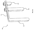
[79]図13は、上部シールド200と同様の形状の下部シールド201を利用する実施形態を示している。幾つかの実施形態では、上部シールド200及び下部シールド201は、側部シールド100に組み込まれて、1個以上の容器を完全に遮蔽するようになっている。幾つかの実施形態では、シールド取付具は、一つ以上の側部シールド100、上部シールド200及び下部シールド201の組合せを一緒に固定して、1個以上の容器を収容するための囲繞体を形成するように設計され得る。幾つかの実施形態では、貯蔵施設の床が適切な遮蔽を可能とするので、下部シールドは必要とされない。幾つかの実施形態では、下部シールドは、床板の連続的なパッドや切片の形態であってもよい。
[79] FIG. 13 shows an embodiment using the
[80]図14は、シールド取付具150の一実施形態を示す。図示されたシールド取付具150は、スロット124,126を備え、スロット124は、変更が加えられたICV(商標)容器上の取付点に被さるよう嵌合し、スロット126は、シールドパネルの取付点に被さるよう嵌合される。スロット付きの取付機構は、シールドパネルの簡単な取付けを助長し、シールドパネルを容易に持ち上げて取り外すことを可能にする。幾つかの実施形態では、シールド取付具150が正確にかつ完全に配置された場合、上面121は容器の上部と面一になり、外面127はシールドパネルの外面と面一になる。幾つかの実施形態では、面121及び面127の一方又は両方は、凹んでいても突出していてもよい。フィレットが施された隅部120は、必要に応じて、シールド取付具150を手又は手工具によって容易に取り外すことを可能にする。典型的には、シールドパネルは取り外して遠隔の場所にて再構成することができる。幾つかの実施形態では、複数のシールド取付具150のうちの一つ以上をシールドと一体化することができる。幾つかの実施形態では、クレーン及び/又はロボットマニピュレータアームが、シールドの再構成のための装置として用いられ、その場合、その装置はその場で、或いは遠隔的に制御され得る。幾つかの実施形態は、シールドの再構成のためのロボット遠隔制御システムを利用することができる。そのようなロボット制御システムの一例は、2017年5月10日に出願された、System and Method for a Robotic Manipulator Armと題される同時係属中の米国特許出願第15/591,978号(優先日2016年5月16日)の明細書に記載されており、その内容全体は参照により本書に援用される。
[80] FIG. 14 shows an embodiment of the
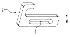
[81]図15A〜図15Cは、図14のシールド取付具の実施形態の変形例を示している。シールド取付具150aは、図14に示すシールド取付具150と同じ特徴の多くを有する。シールド取付具150aは閉じたスロット126aを有するのに対して、シールド取付具150(図14)は開放されたスロット126を有する。図15B及び図15Cは、使用時のシールド取付具150aを示す。閉じたスロット126aは、シールドパネル100のガイド112に取り付けられる。図示実施形態では、シールド取付具150aは、スロット126aがガイド112に沿ってスライドするようシールドパネル100に摺動可能に取り付けられる。図15D及び図15Eは、図15A〜図15Cのシールド取付具の実施形態に対応するシールドパネル100の実施形態を示している。幾つかの実施形態では、シールド取付具150aはシールドパネル100に固定される。ガイド112は、シールド取付具150aを整列させたままにし、シールド取付具150aがシールドパネル100から分離することを防止する。図15Bにおいて、シールド取付具150aは、シールドパネル100及び容器400と完全に係合している。図15Cにおいて、シールド取付具150aは、シールドパネル100及び容器400から突出している。
[81] FIGS. 15A to 15C show a modified example of the embodiment of the shield fixture of FIG. The
[82]このシールドパネルシステムによって、必要に応じてシールドの厚さを簡単に調整することが可能となる。例えば、核廃棄物貯蔵の実施形態では、シールドの厚さは、許容可能な限度(接触時1mSv/時間等)で線量を維持するための調整を必要とすることがある。幾つかの実施形態では、より高放射性レベルの容器が最も内側に貯蔵され、高放射性レベルの容器の遮蔽を増強するために低放射性レベルの容器が最も外側に貯蔵されるよう、容器を貯蔵するとよい。追加の遮蔽が必要な場合は、パネルを積み重ねてシールドの厚さを増やすことができる。 [82] This shield panel system makes it possible to easily adjust the thickness of the shield as needed. For example, in a nuclear waste storage embodiment, the shield thickness may need to be adjusted to maintain the dose within acceptable limits (1 mSv / hour on contact, etc.). In some embodiments, the container is stored so that the container with the higher radioactive level is stored on the innermost side and the container with the lower radioactive level is stored on the outermost side to enhance the shielding of the container with the higher radioactive level. good. If additional shielding is required, panels can be stacked to increase the thickness of the shielding.
[83]図16Aは、様々なシールドの厚さに対して調節することができる調節可能なシールド取付具500の実施形態を示す。シールド取付ペグ530及び容器取付ペグ520の位置は、様々なシールド厚さを補償するために、切抜き溝515の長さに沿ってそれらを摺動させることによって調節することができる。幾つかの実施形態では、シールド取付ペグ530及び容器取付ペグ520は、単一の構成要素としてもよい。図示の実施形態では、ナットは、取付ペグを所定の位置に締め付けて固定するために使用される。しかし、他の固定機構を使用してもよい。図16Bは、厚いシールド100eに用いられている調節可能なシールド取付具500を示している。幾つかの実施形態では、調節可能なシールド取付具500は、トグルクランプ又は他のそのような把持又は固定のための機構をさらに備え得る。
[83] FIG. 16A shows an embodiment of an
[84]図17Aは、異なる厚さの2枚のシールドを受け入れることができる調節可能なシールド取付具550の実施形態を示している。シールド取付ペグ530及び容器取付ペグ520の両方の位置は、シールド厚さの変化を補償するために、切抜き溝515の長さに沿ってそれらを摺動させることによって調節することができる。幾つかの実施形態では、容器取付ペグと、最も近いシールド取付ペグ530とは、単一の構成要素としてもよい。図17Bは、2枚のシールドパネル100と共に使用されている調節可能なシールド取付具550を示している。図示の実施形態では、シールドパネル100は同じ厚さであるが、他の実施形態では、それらは異なる厚さである場合もある。図示の実施形態では、ナットを使用して取付ペグを所定の位置に締め付けて固定しているが、他の固定機構を使用してもよい。幾つかの実施形態では、調節可能なシールド取付具550は、トグルクランプ又は他のそのような把持又は固定のための機構をさらに備え得る。
[84] FIG. 17A shows an embodiment of an
[85]図18は、ガラス固化された核廃棄物を含むICV(商標)容器400の層の例示的な実施形態を示している。図示の実施形態では、容器400は、異なる種類の核廃棄物で満たされている。Hとマークされたものは高レベルの廃棄物を含み、Iとマークされたものは中レベルの廃棄物を含む。一般に、異なる廃棄物レベルを含む貯蔵構造では、より低いレベルの廃棄物が、図6に示される例示的な実施形態のような、より高いレベルの廃棄物のための遮蔽材として使用され得る。より高いレベルの廃棄物に対する追加の遮蔽材として低レベルの廃棄物を使用することができない場合、異なる種類、厚さ及び/又は層の遮蔽材が、より低いレベルの廃棄物に対するよりも、より高いレベルの廃棄物に対して必要とされる。図示の実施形態では、全て同じ遮蔽材が使用されているが、高レベルの廃棄物では遮蔽材は2倍とされている。これは、異なる数及び厚さのシールドパネル100を受け入れることができる調節可能なシールド取付具を有することが有用である場合の例である。
[85] FIG. 18 shows an exemplary embodiment of a layer of
[86]図19A〜図19Cは、一つのグループとして示されている。図19Aは、変更が加えられたシールドパネル100f(図19C)を固定するためにトグルクランプ機構300を利用するシールド取付具150aの実施形態を示す斜視図である。トグルクランプ300は、シールド取付具150aの基部に取り付けられ、シールド取付具パネル150aをクランプ機構300によってシールドパネル100f及びICV(商標)容器400の上部に固定し、シールドが下方に滑り落ちることを防止する。図19Bは、シールド取付具150aの側面図を示している。図19Cは、変更が加えられたシールドパネル100fと共に使用されているシールド取付具150aを示している。一実施形態では、クランプ機構300に使用されるサイズ及び材料は、シールドパネルのサイズ及び構成に基づいて変更することができる。5000ポンドのシールドパネルの場合、100ポンドのシールドパネルよりも、クランプ機構300は丈夫で大きな材料を必要とすることは明らかである。
[86] FIGS. 19A-19C are shown as a group. FIG. 19A is a perspective view showing an embodiment of a
[87]図20は、様々な厚さのシールドパネルを固定するために、トグルクランプシステム300の使用を組み込んだ調節可能なシールド取付具500aの実施形態を示している。図示された実施形態は、様々な厚さのシールドパネルを受け入れるために、シールド取付ペグ530及び容器取付ペグ520を含んでいる。
[87] FIG. 20 shows an embodiment of an
[88]図21Aは、側部シールド100f(図21C)を上部シールド200a(図21B)で固定するシールド取付具700の実施形態を示している。シールド取付具700は、クランプ力及び摩擦により上部シールド200a(図21B)を適所に固定するために用いられ得るエッジグリッパ720を備える。図示の実施形態では、エッジグリッパ720は、シールド取付具700の端部に固定されている。幾つかの実施形態では、エッジグリッパ720をシールド取付具700に一体化することができる。幾つかの実施形態では、シールド取付具は、上部シールド200に一体化することができる。図21Bは、シールド取付具700の実施形態と結合する上部シールド200aの実施形態を示している。図21Cは、シールド取付具700及びシールドパネル100fで使用されている上部シールド200aの実施形態を示している。幾つかの実施形態では、上部シールド200aは、容器の蓋体を正に覆うようなサイズとされている。
[88] FIG. 21A shows an embodiment of a
[89]例示的な実施形態では、1個以上の貯蔵容器がある。2個以上の容器がある場合、それらの容器を互いに近接して配置して、全体的な貯蔵のための面積を減らすとよい。これは、概して述べるならば、貯蔵容器の一つ以上の面が、貯蔵構造において他の貯蔵容器の一つ以上の面と接触しているか、又は非常に近いということを意味する。幾つかの実施形態では、貯蔵構造の内面上には遮蔽材は必要とされない。貯蔵構造における貯蔵容器の露出面(外部又は最外面)は、遮蔽材を必要とすることがある。貯蔵構造を遮蔽するために、一つ以上のモジュ−ル式シールドパネルを露出面に適用してもよい。 [89] In an exemplary embodiment, there is one or more storage containers. If there are two or more containers, it is advisable to place them close to each other to reduce the overall storage area. This generally means that one or more surfaces of the storage container are in contact with or very close to one or more surfaces of the other storage container in the storage structure. In some embodiments, no shielding material is required on the inner surface of the storage structure. The exposed surface (outer or outermost surface) of the storage container in the storage structure may require a shielding material. One or more modular shield panels may be applied to the exposed surface to shield the storage structure.
[90]図22A〜図22Cは、再構成中及び再構成後の貯蔵構造を示す。図22Aは、8個の貯蔵容器400を含む貯蔵構造を示している。図示の実施形態では、見えている貯蔵容器400は、貯蔵構造から取り外されようとしているところのものである。見えている貯蔵容器400を取り外す準備として、上部シールドパネル8(図22C)が取り外され、次いでシールドパネル6,7が取り外されている工程にあるところが示されている。図22Bは、シールドパネル6,7,8(図22C)及び貯蔵容器400(図22A)が取り外され面36,37,38が露出しているときの、図22Aの貯蔵構造を示している。図22Cは、シールドパネル6,7,8が貯蔵容器の露出面36,37,38に取り付けられた後における、図22Bの貯蔵構造を示している。
[例示的実施形態]
[90] FIGS. 22A-22C show storage structures during and after reconstruction. FIG. 22A shows a storage structure containing eight
[Exemplary Embodiment]
[91]以下の実施形態に関連する図、図の要素及び記載された開示内容は、上記において詳細に説明されている。RSPシステムは、一つ以上の貯蔵容器に対してモジュール式の再構成可能な遮蔽を可能にする。例示的な実施形態では、核廃棄物を含む複数の遮蔽されていない貯蔵容器がある。産業界では、核廃棄物を貯蔵する容器は、通常、構造物の一部として(すなわち取外し不可能である)、放射線量を所定の安全限界以下に保つために、そこに含まれる特定の廃棄物レベルのための所要の遮蔽材を備える。この例示的な実施形態では、核廃棄物貯蔵容器は遮蔽されていない。すなわち、特定の廃棄物レベルに必要な遮蔽材がその構造の一部として含まれていないため、核廃棄物のあらゆるレベルを貯蔵するために使用することができる。これらの遮蔽されていない核廃棄物貯蔵容器はモジュール式であり再構成可能である。これは、任意の廃棄物レベルを含むことができ、所与の貯蔵施設に対する所定の線量条件に基づいて必要に応じて適切な遮蔽材を付加することができるからである。 [91] The figures, elements of the figures and the described disclosures relating to the following embodiments are described in detail above. The RSP system allows modular, reconfigurable shielding of one or more storage containers. In an exemplary embodiment, there are multiple unshielded storage containers containing nuclear waste. In industry, containers for storing nuclear waste are usually part of a structure (ie, non-removable), and the specific waste contained therein is used to keep the radiation dose below a prescribed safety limit. Provide the required shielding material for the object level. In this exemplary embodiment, the nuclear waste storage vessel is unshielded. That is, since the shielding material required for a particular waste level is not included as part of its structure, it can be used to store any level of nuclear waste. These unshielded nuclear waste storage vessels are modular and reconfigurable. This is because any waste level can be included and appropriate shielding material can be added as needed based on predetermined dose conditions for a given storage facility.
[92]例示的な実施形態では、遮蔽されていない各核廃棄物貯蔵容器は、1枚以上のモジュール式シールドパネルをその容器に取り付けるための少なくとも一つの取付点を備える。各モジュール式シールドパネルは、遮蔽されていない核廃棄物貯蔵容器に取り付けるための少なくとも一つの取付点を含む。必要とされるシールドパネルの数、及び、シールドパネルと容器上のシールド取付具の数に応じて、一つ以上のシールド取付具を使用して、シールドパネル及び容器の取付点に結合してシールドパネルを容器に取り付ける。幾つかの実施形態では、一つ以上のシールド取付具は、様々な厚さのシールドパネルを受け入れるよう調節可能であるとよい。 [92] In an exemplary embodiment, each unshielded nuclear waste storage vessel comprises at least one attachment point for attaching one or more modular shield panels to the vessel. Each modular shield panel includes at least one attachment point for attachment to an unshielded nuclear waste storage vessel. Depending on the number of shield panels required and the number of shield fixtures on the shield panel and vessel, one or more shield fixtures may be used to join and shield the shield panels and vessel attachment points. Attach the panel to the container. In some embodiments, the one or more shield fittings may be adjustable to accommodate shield panels of various thicknesses.
[93]例示的な実施形態では、複数の核廃棄物貯蔵容器を一緒に貯蔵することができる。一緒に貯蔵される場合、他の貯蔵容器に隣接する側面は遮蔽材を必要としないが、その中に含まれる廃棄物レベル及び特定の貯蔵施設の所定の線量の条件に応じて、貯蔵容器は遮蔽材を必要とすることがある。他の容器に隣接して配置される容器の側面は、その面が隣接する容器によって遮蔽されるため、追加の遮蔽材を必要としない。 [93] In an exemplary embodiment, multiple nuclear waste storage containers can be stored together. When stored together, the sides adjacent to the other storage container do not require shielding, but depending on the waste level contained therein and the prescribed dose conditions of the particular storage facility, the storage container May require shielding material. The sides of the container placed adjacent to the other container do not require additional shielding material as the surface is shielded by the adjacent container.
[94]例示的な実施形態を続けると、貯蔵容器が貯蔵構造に置かれ、特定の廃棄物レベル及び/又は貯蔵施設の条件に従って容器の外側に面するすべての側面が遮蔽される場合、貯蔵構造は完全に遮蔽されているとみなされる。別の遮蔽されていない貯蔵容器を貯蔵構造に付加する必要がある場合、既存の構造のレイアウトに応じて、構造内の1個以上の貯蔵容器から1枚以上のシールドパネルを取り外し、その結果、一つ以上の部分的に遮蔽された貯蔵容器とする。別の遮蔽されていない貯蔵容器は、次に、構造内の一つ以上の部分的に遮蔽された貯蔵容器に隣接する構造内に配置され得る。前に取り外された1枚以上のシールドパネルのうちの1枚以上が、新たに付加された貯蔵容器の外面に設置されてもよい。面がまだ露出している(遮蔽されていない)場合、完全に遮蔽された貯蔵構造とするために、必要に応じて別のシールドパネルを設置するとよい。 [94] Continuing the exemplary embodiment, storage if the storage container is placed in a storage structure and all aspects facing the outside of the container are shielded according to the conditions of a particular waste level and / or storage facility. The structure is considered to be completely shielded. If another unshielded storage container needs to be added to the storage structure, one or more shielded panels may be removed from one or more storage containers in the structure, depending on the layout of the existing structure, and as a result, One or more partially shielded storage containers. Another unoccluded storage vessel may then be placed in the structure adjacent to one or more partially occluded storage vessels in the structure. One or more of the one or more shielded panels previously removed may be placed on the outer surface of the newly added storage container. If the surface is still exposed (unshielded), another shield panel may be installed as needed to ensure a fully shielded storage structure.
[95]開示されたシールドパネル、シールド取付具、及び遮蔽構造のいずれか一つ以上の態様を組み合わせて、本書に明示的に開示されていない他の実施形態を形成してもよいことは明らかである。さらに、シールド取付具は、他の形状をとり、図示のものとは異なる締結具を用いることができる。 [95] It is clear that any one or more aspects of the disclosed shield panels, shield fittings, and shield structures may be combined to form other embodiments not expressly disclosed herein. Is. Further, the shield attachment has another shape, and a fastener different from the one shown in the drawing can be used.
[96]簡単にする目的で、動作は、様々な相互接続された機能ブロック又は別個のソフトウェアモジュールとして説明される。しかしながら、これは必ずしも必要ではなく、これらの機能ブロック又はモジュールが等価的に単一の論理デバイス、プログラム又は不明瞭な境界部の動作に集約される場合がある。いずれにしても、機能ブロック及びソフトウェアモジュール又は記載された機能は、それ自体で、又はハードウェア若しくはソフトウェアのいずれかの他の動作と組み合わせて実装することができる。 [96] For simplicity, operations are described as various interconnected functional blocks or separate software modules. However, this is not always necessary and these functional blocks or modules may be equivalently aggregated into a single logical device, program or obscure boundary operation. In any case, the functional blocks and software modules or the described functions may be implemented on their own or in combination with any other operation of the hardware or software.
[97]本書に開示されたシステム、方法、プロセス及び/又は装置の原理をその好ましい実施形態で説明し例示したが、システム、方法、プロセス及び/又は装置は、そのような原理から逸脱することなく、構成や詳細部を変形できることは明らかであろう。添付の特許請求の範囲の精神及び範囲内に入るすべての修正及び変形を請求するものである。
[97] Although the principles of systems, methods, processes and / or devices disclosed herein have been described and illustrated in their preferred embodiments, the systems, methods, processes and / or devices shall deviate from such principles. It will be clear that the configuration and details can be modified without it. It claims all modifications and modifications that fall within the spirit and scope of the appended claims.
Claims (15)
1枚以上のモジュール式シールドパネルと、
一つ以上の貯蔵容器と
を備え、
貯蔵構造における前記一つ以上の貯蔵容器の全ての露出面が前記1枚以上のシールドパネルの一つと作動的に結合されるように、前記一つ以上の貯蔵容器が前記貯蔵構造を形成し、前記貯蔵構造が、前記一つ以上の貯蔵容器の付加と取外しのうちの少なくとも一方を行うために作動的に再構成可能となっており、
前記貯蔵構造から、少なくとも第1の結合されたモジュール式シールドパネルを取り外すことによって、前記貯蔵構造における第1の貯蔵容器の第1の露出面をもたらし、
少なくとも前記第1の結合されたモジュール式シールドパネルの取外しに応答して、前記貯蔵構造からの前記第1の貯蔵容器の取外しと、前記貯蔵構造への第2の貯蔵容器の付加とのうちの少なくとも一方を行い、前記第2の貯蔵容器の付加が、前記第1の貯蔵容器の前記第1の露出面に隣接して前記第2の貯蔵容器の第2の露出面を配置することを含み、
前記第1の結合されたモジュール式シールドパネルが、前記第2の貯蔵容器と第3の貯蔵容器の少なくとも一方にある第3の露出面に再設置され、
前記第1の結合されたモジュール式シールドパネルの再設置に応答して、あらゆる残りの露出面が確認され、
前記貯蔵構造における前記残りの露出面に補充的なモジュール式シールドパネルを付加することによって、新規に遮蔽された貯蔵構造がもたらされ、
前記一つ以上の貯蔵容器の各々が、より低レベルの放射性廃棄物またはより高レベルの放射性廃棄物の一つを内包し、
前記より高レベルの放射性廃棄物を備えた前記一つ以上の貯蔵容器が前記貯蔵構造の中央部に配置され、前記より低レベルの放射性廃棄物を備えた前記一つ以上の貯蔵容器が前記貯蔵構造の最も外側にある、再構成可能なモジュール式遮蔽システム。 A reconfigurable modular shielding system for storage containers,
With one or more modular shield panels
Equipped with one or more storage containers,
The one or more storage containers form the storage structure so that all exposed surfaces of the one or more storage containers in the storage structure are operatively coupled to one of the one or more shielded panels. The storage structure is operably reconfigurable to perform at least one of the addition and removal of the one or more storage containers.
Removing at least the first coupled modular shield panel from the storage structure provides a first exposed surface of the first storage container in the storage structure.
Of the removal of the first storage container from the storage structure and the addition of the second storage container to the storage structure, at least in response to the removal of the first coupled modular shield panel. Doing at least one, the addition of the second storage container comprises placing the second exposed surface of the second storage container adjacent to the first exposed surface of the first storage container. ,
The first coupled modular shield panel is re-installed on a third exposed surface on at least one of the second storage container and the third storage container.
In response to the re-installation of the first coupled modular shield panel, all remaining exposed surfaces were identified.
The addition of a complementary modular shield panel to the remaining exposed surface of the storage structure provides a newly shielded storage structure.
Each of the one or more storage container, encloses a single lower-level radioactive waste or from high-level radioactive waste,
Wherein from the one or more storage containers with high levels of radioactive waste is disposed in a central portion of the storage structure, the more the with low levels of radioactive waste more than one storage container above the storage A reconfigurable modular shielding system on the outermost side of the structure.
Priority Applications (1)
| Application Number | Priority Date | Filing Date | Title |
|---|---|---|---|
| JP2021159776A JP7472418B2 (en) | 2016-05-26 | 2021-09-29 | System for a storage container having removable shield panels - Patents.com |
Applications Claiming Priority (3)
| Application Number | Priority Date | Filing Date | Title |
|---|---|---|---|
| US201662342028P | 2016-05-26 | 2016-05-26 | |
| US62/342,028 | 2016-05-26 | ||
| PCT/US2017/034075 WO2017205427A1 (en) | 2016-05-26 | 2017-05-23 | System for storage container with removable shield panels |
Related Child Applications (1)
| Application Number | Title | Priority Date | Filing Date |
|---|---|---|---|
| JP2021159776A Division JP7472418B2 (en) | 2016-05-26 | 2021-09-29 | System for a storage container having removable shield panels - Patents.com |
Publications (2)
| Publication Number | Publication Date |
|---|---|
| JP2019519751A JP2019519751A (en) | 2019-07-11 |
| JP6958867B2 true JP6958867B2 (en) | 2021-11-02 |
Family
ID=59014769
Family Applications (2)
| Application Number | Title | Priority Date | Filing Date |
|---|---|---|---|
| JP2018546660A Active JP6958867B2 (en) | 2016-05-26 | 2017-05-23 | System for storage containers with removable shielded panels |
| JP2021159776A Active JP7472418B2 (en) | 2016-05-26 | 2021-09-29 | System for a storage container having removable shield panels - Patents.com |
Family Applications After (1)
| Application Number | Title | Priority Date | Filing Date |
|---|---|---|---|
| JP2021159776A Active JP7472418B2 (en) | 2016-05-26 | 2021-09-29 | System for a storage container having removable shield panels - Patents.com |
Country Status (5)
| Country | Link |
|---|---|
| US (2) | US10311989B2 (en) |
| EP (1) | EP3465696B1 (en) |
| JP (2) | JP6958867B2 (en) |
| CA (2) | CA3157531C (en) |
| WO (1) | WO2017205427A1 (en) |
Families Citing this family (10)
| Publication number | Priority date | Publication date | Assignee | Title |
|---|---|---|---|---|
| JP6958867B2 (en) * | 2016-05-26 | 2021-11-02 | ヴェオリア ニュークリア ソリューションズ インコーポレイテッドVeolia Nuclear Solutions Inc. | System for storage containers with removable shielded panels |
| US10600522B2 (en) * | 2017-04-10 | 2020-03-24 | United States Of America As Represented By The Administrator Of Nasa | Method of making thin atomic (Z) grade shields |
| US11147277B2 (en) * | 2019-06-04 | 2021-10-19 | Wolfe Electric, Inc. | Conveyor tunnel oven |
| JP7257280B2 (en) * | 2019-07-29 | 2023-04-13 | 三菱重工業株式会社 | Radioactive waste storage method, radioactive waste storage container, and radioactive waste storage container assembly unit |
| US20250128304A1 (en) * | 2021-08-13 | 2025-04-24 | Veolia Nuclear Solutions, Inc. | Systems and Methods for Vitrification Process Control |
| CN113921160B (en) * | 2021-09-28 | 2023-09-12 | 中国核电工程有限公司 | Disposal unit structure for temporary storage of decommissioning intermediate-level radioactive waste |
| JP2025504903A (en) | 2022-01-24 | 2025-02-19 | ヴェオリア ニュークリア ソリューションズ インコーポレイテッド | Systems and methods for electrode feeders and electrode seals - Patents.com |
| US20240412024A1 (en) * | 2023-06-07 | 2024-12-12 | Toshiba Global Commerce Solutions, Inc. | Selective radio frequency identification shielding |
| CN116844748A (en) * | 2023-07-21 | 2023-10-03 | 同方威视科技江苏有限公司 | Transfer device and check out test set of radiation source |
| WO2025188910A1 (en) | 2024-03-05 | 2025-09-12 | Veolia Nuclear Solutions, Inc. | Systems and methods for a multistage melter |
Family Cites Families (27)
| Publication number | Priority date | Publication date | Assignee | Title |
|---|---|---|---|---|
| US3562975A (en) * | 1969-01-14 | 1971-02-16 | Charles W Moss | Prefabricated shelter and method of erecting same |
| JPS5610295A (en) * | 1979-07-04 | 1981-02-02 | Mitsui Shipbuilding Eng | Container for transporting radioactive material |
| JPS62167195U (en) * | 1986-04-15 | 1987-10-23 | ||
| US5493832A (en) * | 1993-11-26 | 1996-02-27 | Abrams; Ned H. | Modular wall unit, system and method for making storage containers and barriers |
| FR2762132B1 (en) * | 1997-04-10 | 1999-06-18 | Commissariat Energie Atomique | TRANSPORTATION PACKAGE FOR DANGEROUS PACKAGES, SUCH AS HIGH-ACTIVITY NUCLEAR PACKAGES |
| JP2974653B2 (en) * | 1998-04-03 | 1999-11-10 | 株式会社オー・シー・エル | Storage Cask Storage Method and Shield |
| JP2001281397A (en) * | 2000-03-30 | 2001-10-10 | Toshiba Corp | Radiation shielding device |
| US6283908B1 (en) | 2000-05-04 | 2001-09-04 | Radioactive Isolation Consortium, Llc | Vitrification of waste with conitnuous filling and sequential melting |
| AUPR303001A0 (en) * | 2001-02-13 | 2001-03-08 | Rees Operations Pty Ltd | Panel/gate interconnection means for a collapsible materials handling container |
| US7211038B2 (en) | 2001-09-25 | 2007-05-01 | Geosafe Corporation | Methods for melting of materials to be treated |
| JP2003121591A (en) * | 2001-10-15 | 2003-04-23 | Mitsubishi Electric Corp | Radiation shielding wall |
| JP2003270382A (en) * | 2002-03-12 | 2003-09-25 | Mitsubishi Heavy Ind Ltd | Radioactive material containment vessel and radioactive material containment method |
| AU2003231516A1 (en) | 2002-05-16 | 2003-12-02 | Tokyo Electron Limited | Method of treating substrate |
| JP2007315843A (en) * | 2006-05-24 | 2007-12-06 | Takenaka Komuten Co Ltd | γ-ray shielding panel material, γ-ray shielding seal material, and γ-ray shielding structure |
| US20080276554A1 (en) * | 2007-05-07 | 2008-11-13 | Sheetz Michael A | Modular Radiation Shielding System and Related Methods |
| US8111025B2 (en) * | 2007-10-12 | 2012-02-07 | Varian Medical Systems, Inc. | Charged particle accelerators, radiation sources, systems, and methods |
| PL213378B1 (en) * | 2007-11-06 | 2013-02-28 | Corning Cable Systems Polska Spolka Z Ograniczona Odpowiedzialnoscia | Modular switch box for optical fibre wires and system of modular switch boxes for optical fibre wires |
| US20100294960A1 (en) * | 2009-05-19 | 2010-11-25 | Innovative American Technology, Inc. | Modular radiation shield |
| US9981868B2 (en) | 2010-04-02 | 2018-05-29 | Kurion, Inc. | Mobile processing system for hazardous and radioactive isotope removal |
| JP2012247321A (en) * | 2011-05-27 | 2012-12-13 | Hiroshi Yamada | Method for treating nuclear fuel polluted water |
| CN103858175A (en) * | 2011-09-08 | 2014-06-11 | 霍尔泰克国际股份有限公司 | Ventilated system for storing high level radioactive waste |
| JP2015099098A (en) * | 2013-11-19 | 2015-05-28 | 日軽金アクト株式会社 | Shield structure |
| US9865366B2 (en) * | 2014-07-10 | 2018-01-09 | Energysolutions, Llc | Shielded packaging system for radioactive waste |
| EP3251122B1 (en) | 2015-02-01 | 2019-04-10 | Kurion, Inc. | Ion specific media removal from vessel for vitrification |
| CN107533873B (en) * | 2015-05-04 | 2019-07-30 | 霍尔泰克国际公司 | Fuel basket for spent nuclear fuel and its implementation container |
| JP2015222270A (en) * | 2015-08-07 | 2015-12-10 | Jfe建材株式会社 | Radioactive contaminant storage facility |
| JP6958867B2 (en) * | 2016-05-26 | 2021-11-02 | ヴェオリア ニュークリア ソリューションズ インコーポレイテッドVeolia Nuclear Solutions Inc. | System for storage containers with removable shielded panels |
-
2017
- 2017-05-23 JP JP2018546660A patent/JP6958867B2/en active Active
- 2017-05-23 CA CA3157531A patent/CA3157531C/en active Active
- 2017-05-23 EP EP17728346.2A patent/EP3465696B1/en active Active
- 2017-05-23 CA CA3016365A patent/CA3016365C/en active Active
- 2017-05-23 US US15/603,222 patent/US10311989B2/en active Active
- 2017-05-23 WO PCT/US2017/034075 patent/WO2017205427A1/en not_active Ceased
-
2019
- 2019-05-08 US US16/407,002 patent/US10770193B2/en active Active
-
2021
- 2021-09-29 JP JP2021159776A patent/JP7472418B2/en active Active
Also Published As
| Publication number | Publication date |
|---|---|
| US10770193B2 (en) | 2020-09-08 |
| JP2019519751A (en) | 2019-07-11 |
| WO2017205427A1 (en) | 2017-11-30 |
| CA3016365C (en) | 2022-06-14 |
| EP3465696A1 (en) | 2019-04-10 |
| CA3157531A1 (en) | 2017-11-30 |
| EP3465696B1 (en) | 2020-04-15 |
| US20200027611A1 (en) | 2020-01-23 |
| CA3016365A1 (en) | 2017-11-30 |
| US20170345522A1 (en) | 2017-11-30 |
| JP7472418B2 (en) | 2024-04-23 |
| US10311989B2 (en) | 2019-06-04 |
| CA3157531C (en) | 2023-08-15 |
| JP2022003341A (en) | 2022-01-11 |
Similar Documents
| Publication | Publication Date | Title |
|---|---|---|
| JP6958867B2 (en) | System for storage containers with removable shielded panels | |
| KR102305376B1 (en) | Systems and methods for transferring spent nuclear fuel from wet storage to dry storage | |
| CA2953522C (en) | Shielded packaging system for radioactive waste | |
| CN101960534B (en) | Apparatus for supporting radioactive fuel assemblies | |
| US8208597B2 (en) | Channel confinement system and method for dry-storage of BWR fuel bundles | |
| WO2008097381A3 (en) | Apparatus and method for transporting and/or storing radioactive materials | |
| US10020084B2 (en) | System and method for processing spent nuclear fuel | |
| JP6301916B2 (en) | Optimal method for loading radioactive elements into packages | |
| JPH0224599A (en) | Cask for transporting radioactive material | |
| Rechard et al. | Feasibility of Direct Disposal of Salt Waste from Electochemical Processing of Spent Nuclear Fuel | |
| Zillmer et al. | BRR cask use for Pu-238 isotope production | |
| Rechard et al. | Feasibility of Direct Disposal of Electrorefiner Salt Waste. | |
| Ammerman | Transportation of spent nuclear fuel and high-level radioactive waste after long-term storage | |
| Stuke et al. | Storage and transport | |
| Saegusa et al. | A'holistic'approach for licensing the transport and storage of metal casks for spent nuclear fuel. | |
| Funke et al. | CASTOR® 1000/19: development and design of a new transport and storage cask | |
| Krementz et al. | Feasibility Study For Use Of Commercial Cask Vendor Dry Transfer Systems To Unload Used Fuel Assemblies In L-Area | |
| Martinez et al. | Design of a Universal Canister System for US High-Level Waste | |
| Swift | Spent Fuel Management and Disposition. | |
| Vertut et al. | The Teletrans Concept for Remote Maintenance of Tokomak Reactors | |
| Benitez-Navarro et al. | Current approaches on the management of disused sealed sources in Bulgaria | |
| Funke et al. | CASTOR {sup R} 1000/19: Development and Design of a New Transport and Storage Cask | |
| Richardson | Yours sincerely | |
| Moore et al. | TRU partnership: Overview of technical challenges and initiatives | |
| Voßnacke et al. | CASTOR registered HAW28M-a high heat load cask for transport and storage of vitrified high level waste containers |
Legal Events
| Date | Code | Title | Description |
|---|---|---|---|
| RD04 | Notification of resignation of power of attorney |
Free format text: JAPANESE INTERMEDIATE CODE: A7424 Effective date: 20190918 |
|
| A621 | Written request for application examination |
Free format text: JAPANESE INTERMEDIATE CODE: A621 Effective date: 20200226 |
|
| A977 | Report on retrieval |
Free format text: JAPANESE INTERMEDIATE CODE: A971007 Effective date: 20201125 |
|
| A131 | Notification of reasons for refusal |
Free format text: JAPANESE INTERMEDIATE CODE: A131 Effective date: 20201201 |
|
| A601 | Written request for extension of time |
Free format text: JAPANESE INTERMEDIATE CODE: A601 Effective date: 20210222 |
|
| A521 | Request for written amendment filed |
Free format text: JAPANESE INTERMEDIATE CODE: A523 Effective date: 20210427 |
|
| A521 | Request for written amendment filed |
Free format text: JAPANESE INTERMEDIATE CODE: A523 Effective date: 20210506 |
|
| TRDD | Decision of grant or rejection written | ||
| A01 | Written decision to grant a patent or to grant a registration (utility model) |
Free format text: JAPANESE INTERMEDIATE CODE: A01 Effective date: 20210907 |
|
| A61 | First payment of annual fees (during grant procedure) |
Free format text: JAPANESE INTERMEDIATE CODE: A61 Effective date: 20210929 |
|
| R150 | Certificate of patent or registration of utility model |
Ref document number: 6958867 Country of ref document: JP Free format text: JAPANESE INTERMEDIATE CODE: R150 |
|
| R250 | Receipt of annual fees |
Free format text: JAPANESE INTERMEDIATE CODE: R250 |
|
| R250 | Receipt of annual fees |
Free format text: JAPANESE INTERMEDIATE CODE: R250 |