JP6958508B2 - Harvesting work system - Google Patents
Harvesting work system Download PDFInfo
- Publication number
- JP6958508B2 JP6958508B2 JP2018145894A JP2018145894A JP6958508B2 JP 6958508 B2 JP6958508 B2 JP 6958508B2 JP 2018145894 A JP2018145894 A JP 2018145894A JP 2018145894 A JP2018145894 A JP 2018145894A JP 6958508 B2 JP6958508 B2 JP 6958508B2
- Authority
- JP
- Japan
- Prior art keywords
- combine
- field
- traveling
- photographed
- camera
- Prior art date
- Legal status (The legal status is an assumption and is not a legal conclusion. Google has not performed a legal analysis and makes no representation as to the accuracy of the status listed.)
- Active
Links
- 238000003306 harvesting Methods 0.000 title claims description 41
- 238000000034 method Methods 0.000 description 51
- 238000003860 storage Methods 0.000 description 34
- 230000008569 process Effects 0.000 description 33
- 230000010365 information processing Effects 0.000 description 18
- 238000012545 processing Methods 0.000 description 17
- 230000005856 abnormality Effects 0.000 description 10
- 230000000694 effects Effects 0.000 description 7
- 230000002093 peripheral effect Effects 0.000 description 7
- 238000010586 diagram Methods 0.000 description 6
- 230000005540 biological transmission Effects 0.000 description 4
- 239000000428 dust Substances 0.000 description 4
- 230000032258 transport Effects 0.000 description 4
- XLYOFNOQVPJJNP-UHFFFAOYSA-N water Substances O XLYOFNOQVPJJNP-UHFFFAOYSA-N 0.000 description 4
- 238000011156 evaluation Methods 0.000 description 3
- 238000009333 weeding Methods 0.000 description 3
- 238000004891 communication Methods 0.000 description 2
- 230000006866 deterioration Effects 0.000 description 2
- 238000007599 discharging Methods 0.000 description 2
- 238000013507 mapping Methods 0.000 description 2
- 238000012986 modification Methods 0.000 description 2
- 230000004048 modification Effects 0.000 description 2
- 230000007935 neutral effect Effects 0.000 description 2
- 239000000126 substance Substances 0.000 description 2
- RZVHIXYEVGDQDX-UHFFFAOYSA-N 9,10-anthraquinone Chemical compound C1=CC=C2C(=O)C3=CC=CC=C3C(=O)C2=C1 RZVHIXYEVGDQDX-UHFFFAOYSA-N 0.000 description 1
- 241000196324 Embryophyta Species 0.000 description 1
- 230000002159 abnormal effect Effects 0.000 description 1
- 238000004458 analytical method Methods 0.000 description 1
- 238000013459 approach Methods 0.000 description 1
- 230000008859 change Effects 0.000 description 1
- 230000001934 delay Effects 0.000 description 1
- 238000001514 detection method Methods 0.000 description 1
- 238000009313 farming Methods 0.000 description 1
- 239000000446 fuel Substances 0.000 description 1
- 230000006870 function Effects 0.000 description 1
- 230000005484 gravity Effects 0.000 description 1
- 238000010191 image analysis Methods 0.000 description 1
- 238000005259 measurement Methods 0.000 description 1
- 238000012544 monitoring process Methods 0.000 description 1
- 239000002245 particle Substances 0.000 description 1
- 230000004044 response Effects 0.000 description 1
- 239000010902 straw Substances 0.000 description 1
- 230000002194 synthesizing effect Effects 0.000 description 1
- 239000002699 waste material Substances 0.000 description 1
Images


Landscapes
- Guiding Agricultural Machines (AREA)
- Harvester Elements (AREA)
- Control Of Position, Course, Altitude, Or Attitude Of Moving Bodies (AREA)
Description
本発明は、収穫作業システムに関する。 The present invention relates to a harvesting work system.
従来、特許文献1に例示するように、圃場内に設定された走行経路に沿ってコンバインを自動走行させながら収穫作業を行わせる技術が知られている。 Conventionally, as illustrated in Patent Document 1, there is known a technique for performing a harvesting operation while automatically traveling a combine along a traveling path set in a field.
また、特許文献2に例示するように、カメラを備えた無人飛行体によって圃場を撮影し、作物の生育状態を検出する技術が知られている。
Further, as illustrated in
しかしながら、上記の特許文献には、コンバインの自動走行に無人飛行体の撮影情報を反映させる技術が開示されていない。 However, the above-mentioned patent document does not disclose a technique for reflecting the shooting information of an unmanned vehicle in the automatic traveling of the combine.
また、コンバインに搭載されたセンサーやカメラでは、コンバインから大きく離れた位置での作物の状態や障害物の存在等を検出することができず、対応が遅れ、作物の収穫損失や障害物との衝突を来すおそれがある。 In addition, the sensors and cameras mounted on the combine cannot detect the condition of crops and the presence of obstacles at a position far away from the combine, which delays the response and causes crop loss losses and obstacles. There is a risk of collision.
本発明は、コンバインから離れた位置での作物の状態や障害物の存在を、圃場上空を飛行する無人飛行体からの撮影情報によって検出し、収穫作業を円滑に行える収穫作業システムを提供することを目的とする。 The present invention provides a harvesting work system capable of smoothly performing harvesting work by detecting the state of crops and the presence of obstacles at a position away from the combine from photographed information from an unmanned flying object flying over the field. With the goal.
上述した課題を解決するために、本発明は以下の技術的手段を講じる。 In order to solve the above-mentioned problems, the present invention takes the following technical measures.
すなわち、請求項1記載の発明は、コンバインと無人飛行体から構成される収穫作業システムであって、前記コンバインには、前記無人飛行体からの情報を受信すると共に、圃場内に設定された走行経路に沿って機体を自動走行させながら収穫作業を行わせる制御部を備え、前記無人飛行体には、機体に備えたカメラによる撮影情報を前記コンバインに送信すると共に、圃場上空に設定された飛行経路、またはコンバインの機体に対して設定された位置を飛行させる制御部を備え、前記カメラで撮影された映像により、前記コンバインの機体の周辺に人の存在を認識した場合に前記機体の走行を停止させ、この走行停止状態において前記コンバインの操縦席の作業者が停止解除操作を行うことで、前記機体を走行可能な状態に復帰させることを特徴とする収穫作業システムとする。 That is, the invention according to claim 1 is a harvesting work system composed of a combine and an unmanned airframe, and the combine receives information from the unmanned airframe and travels set in a field. It is equipped with a control unit that automatically runs the aircraft along the route to perform harvesting work, and the unmanned aircraft transmits information taken by the camera provided on the aircraft to the combine and flies set over the field. It is equipped with a control unit that flies a route or a position set with respect to the combine harvester, and when the presence of a person is recognized in the vicinity of the combine harvester from the image taken by the camera, the vehicle travels. The harvesting work system is characterized in that the combine is stopped and the operator in the driver's seat of the combine performs a stop release operation in the traveling stopped state to return the aircraft to a traveling state.
請求項2記載の発明は、前記無人飛行体をコンバインよりも先行する位置に飛行させ、前記カメラによって圃場の植立穀稈を撮影し、この撮影情報から植立穀稈の倒伏状態を検出し、この倒伏状態に応じてコンバインの作業走行速度を変速制御する構成とした請求項1記載の収穫作業システムとする。 According to the second aspect of the present invention, the unmanned vehicle is flown to a position ahead of the combine harvester, the planted culm in the field is photographed by the camera, and the collapsed state of the planted culm is detected from the photographed information. The harvesting work system according to claim 1, wherein the work running speed of the combine is controlled in a variable speed according to the collapsed state.
請求項3記載の発明は、前記カメラによる撮影情報から圃場内の複数領域での植立穀稈の倒伏状態を検出し、この倒伏状態に応じてコンバインの作業走行速度を各領域ごとに変速制御する構成とした請求項2記載の収穫作業システムとする。
According to the third aspect of the present invention, the lodging state of the planted culm in a plurality of regions in the field is detected from the information taken by the camera, and the working running speed of the combine is controlled by shifting for each region according to the lodging state. The harvesting work system according to
請求項4記載の発明は、前記無人飛行体をコンバインよりも先行する位置に飛行させ、前記カメラによって圃場の植立穀稈を撮影し、この撮影情報から植立穀稈の倒伏状態を検出し、この倒伏状態に応じてコンバインの刈取装置を圃場面近傍の高さに位置付ける構成とした請求項1記載の収穫作業システムとする。 According to the fourth aspect of the present invention, the unmanned flying object is made to fly at a position ahead of the combine, the planted culm in the field is photographed by the camera, and the lodging state of the planted culm is detected from the photographed information. The harvesting work system according to claim 1, wherein the combine cutting device is positioned at a height near the field scene according to the lodging state.
請求項5記載の発明は、前記無人飛行体に備えたカメラによってコンバインと圃場を同時に撮影し、この撮影情報からコンバインの走行方向が設定された走行経路に対してずれていることが検出された場合に、コンバインを設定された走行経路に復帰させる操向制御がなされる構成とした請求項1記載の収穫作業システムとする。
In the invention according to
請求項6記載の発明は、前記無人飛行体に備えたカメラによってコンバインと圃場を同時に撮影し、この撮影情報からコンバインの前方に障害物があることが検出された場合に、コンバインの走行と刈取装置の駆動を自動的に停止させる構成とした請求項1記載の収穫作業システムとする。 According to the sixth aspect of the present invention, the combine and the field are simultaneously photographed by a camera provided on the unmanned vehicle, and when an obstacle is detected in front of the combine from the photographed information, the combine is driven and harvested. The harvesting work system according to claim 1, wherein the drive of the device is automatically stopped.
請求項7記載の発明は、前記無人飛行体に備えたカメラによってコンバインと圃場を同時に撮影し、この撮影情報からコンバインの前方に障害物があることが判定された場合に、この障害物を回避するようにコンバインを自動的に操向する構成とした請求項1記載の収穫作業システムとする。 The invention according to claim 7 avoids the combine when the combine and the field are simultaneously photographed by the camera provided on the unmanned vehicle and it is determined from the photographed information that there is an obstacle in front of the combine. The harvesting work system according to claim 1, wherein the combine is automatically steered so as to be used.
請求項1記載の発明によれば、無人飛行体に備えたカメラによる撮影情報をコンバインに送信することで、コンバインから離れた位置の状態を検出してコンバインの作業走行を適正化することができ、収穫作業を円滑に行うことができる。また、コンバイン周辺の全性を確保することができる。 According to the invention of claim 1, by transmitting the shooting information by the camera provided in the unmanned vehicle to the combine, it is possible to detect the state of the position away from the combine and optimize the work running of the combine. , Harvesting work can be done smoothly. In addition, the integrity around the combine can be ensured.
請求項2記載の発明によれば、請求項1に記載の発明の効果に加えて、無人飛行体に備えたカメラによる撮影情報から植立穀稈の倒伏状態を検出し、この倒伏状態に応じてコンバインの作業走行速度を変速制御するので、コンバインの前方の位置に植立穀稈の倒伏が検出された場合には、この倒伏した穀稈を刈り取る前に作業走行速度を減速し、倒伏穀稈を引き起こして刈り取ることができ、収穫損失の発生を少なくすることができる。
According to the invention of
請求項3記載の発明によれば、請求項2記載の発明の効果に加えて、無人飛行体に備えたカメラによる撮影情報から圃場内の複数領域での植立穀稈の倒伏状態を検出し、この倒伏状態に応じてコンバインの作業走行速度を各領域ごとに変速制御するので、コンバインの前方領域に植立穀稈の倒伏が検出された場合には、この倒伏した穀稈を刈り取る前に作業走行速度を減速し、倒伏穀稈を引き起こして刈り取ることができ、収穫損失の発生を少なくすることができる。
According to the invention of claim 3, in addition to the effect of the invention of
請求項4記載の発明によれば、請求項1記載の発明の効果に加えて、無人飛行体をコンバインよりも先行する位置に飛行させ、カメラによって圃場の植立穀稈を撮影し、この撮影情報から植立穀稈の倒伏状態を検出し、この倒伏状態に応じてコンバインの刈取装置を圃場面近傍の高さに位置付けるので、倒伏した穀稈でも引き起こして刈り取ることができ、収穫損失の発生を少なくすることができる。 According to the invention of claim 4, in addition to the effect of the invention of claim 1, the unmanned flying object is flown to a position ahead of the combine, and the planted culm in the field is photographed by a camera, and this photographing is performed. The collapsed state of the planted culm is detected from the information, and the combine reaping device is positioned at a height near the field scene according to this laid down state. Can be reduced.
請求項5記載の発明によれば、請求項1記載の発明の効果に加えて、無人飛行体に備えたカメラによってコンバインと圃場を同時に撮影し、この撮影情報からコンバインの走行方向が設定された走行経路に対してずれていることが検出された場合に、コンバインを設定された走行経路に復帰させる操向制御がなされるので、設定経路を飛行する無人飛行体によってコンバインの走行状態を監視し、異常な走行が行われた場合でも、このコンバインを設定された走行経路に復帰させることができる。
According to the invention of
請求項6記載の発明によれば、請求項1記載の発明の効果に加えて、無人飛行体に備えたカメラによってコンバインと圃場を同時に撮影し、この撮影情報からコンバインの前方に障害物があることが検出された場合に、コンバインの走行と刈取装置の駆動を自動的に停止させるので、圃場内の障害物との衝突を避けることができる。 According to the invention of claim 6, in addition to the effect of the invention of claim 1, the combine and the field are simultaneously photographed by a camera provided on the unmanned vehicle, and there is an obstacle in front of the combine from this photographed information. When this is detected, the traveling of the combine and the driving of the harvester are automatically stopped, so that collision with an obstacle in the field can be avoided.
請求項7記載の発明によれば、請求項1記載の発明の効果に加えて、無人飛行体に備えたカメラによってコンバインと圃場を同時に撮影し、この撮影情報からコンバインの前方に障害物があることが判定された場合に、この障害物を回避するようにコンバインを自動的に操向するので、圃場内の障害物を回避して作業走行を継続することができる。 According to the invention of claim 7, in addition to the effect of the invention of claim 1, the combine and the field are simultaneously photographed by a camera provided on the unmanned vehicle, and there is an obstacle in front of the combine from this photographed information. When it is determined that the combine is automatically steered to avoid this obstacle, the work can be continued while avoiding the obstacle in the field.
以下に、本発明の実施形態を図面に基づいて詳細に説明する。なお、実施形態における構成要素には、当業者が容易に想定できるもの、あるいは実質的に同一のもの、いわゆる均等の範囲のものが含まれる。そして、以下の実施形態により本発明が限定されるものではない。 Hereinafter, embodiments of the present invention will be described in detail with reference to the drawings. The components in the embodiment include those that can be easily assumed by those skilled in the art, or those that are substantially the same, that is, those having a so-called equal range. The present invention is not limited to the following embodiments.
図1は、実施形態に係るコンバインの制御システム1の概要説明図である。なお、このコンバインの制御システム1は、各種作業車両の作業管理システムに組み込まれる。図1においては、コンバインの制御システム1を一点鎖線で示している。図1に示すように、コンバインの制御システム1は、コンバイン2と、無人飛行体20とを備える。
FIG. 1 is a schematic explanatory view of the combine control system 1 according to the embodiment. The combine control system 1 is incorporated into a work management system for various work vehicles. In FIG. 1, the combine control system 1 is shown by a alternate long and short dash line. As shown in FIG. 1, the combine control system 1 includes a
また、コンバインの制御システム1は、後述する記憶装置152や情報処理装置(図示省略)を備えるコンピュータにより構築された機体制御部150と、タブレット端末のように携行自在であり、制御部100と有線あるいは無線で接続可能な情報処理端末10とを備える(図5参照)。
Further, the combine control system 1 is portable like a tablet terminal and a machine control unit 150 constructed by a computer equipped with a storage device 152 and an information processing device (not shown), which will be described later, and is wired to the
また、情報処理端末10は、基地局50を介して、インターネットあるいは所定の通信網に接続される。情報処理端末10は、たとえば、コンバインの制御システム1による作業管理を行う管理者が所有するサーバ、およびパーソナルコンピュータなどの複数の端末装置を接続している。なお、端末装置からも、サーバを介して、コンバインの制御システム1の作業管理が可能である。
Further, the
コンバイン(以下、機体という)2は、走行装置3と、作業装置4とを備える。なお、走行装置3および作業装置4については、図2および図3を用いて後述する。機体2には、キャビン5の上部にGPS(Global Positioning System)アンテナやGNSS(Global Navigation Satellite System)アンテナなどの受信アンテナ6が設けられる。
The combine (hereinafter referred to as an airframe) 2 includes a traveling device 3 and a working device 4. The traveling device 3 and the working device 4 will be described later with reference to FIGS. 2 and 3. The
また、キャビン5は、機体フレームの前部に設けられ、作業者(操縦者ともいう)が着席する操縦席5bの他、各種操作レバーや計器類、さらには、情報処理端末10や各種情報を表示する表示部(モニタ)12などが設けられた操縦部5aを内部空間に有する。
Further, the
一方、無人飛行体20は、ドローンと呼ばれる飛行体であり、コントローラ(制御部)200(図5参照)と、カメラ22と、複数の航法衛星Sから送信される電波を受信して自己位置を測定する測位装置21(図5参照)とを備える。無人飛行体(以下、ドローンという)20は、機体2周辺や圃場の上空を飛行しながら、カメラ22による機体2や機体2周辺、圃場の撮影を行う。なお、コントローラ200は、記憶装置や情報処理装置を有するコンピュータから構成される。
On the other hand, the unmanned
上記したような作業管理システムにおいて、たとえば、機体2側に設けられた制御部100は、ドローン20のカメラ22で撮像された画像(画像情報)と、測位装置21に取得されたカメラ22による撮像位置を示す位置情報とを合成処理して圃場情報を生成し、生成した圃場情報に基づいて作業管理処理を実行する。
In the work management system as described above, for example, the
次に、図2および図3を参照してコンバイン2の構成について説明する。図2は、コンバイン2の概略側面図であり、図3は、コンバイン2の概略平面図である。なお、以下の説明では、コンバイン(機体)2の通常の使用態様時における前後方向、左右方向、上下方向を、各部位におけるそれぞれの前後方向、左右方向、上下方向として説明する。
Next, the configuration of the
このうち、「前」方は、刈り取り作業時における機体2の進行方向であり、「左」方は、前方に向かって左手方向であり、「右」方は、前方に向かって右手方向であり、また、「下」方は、重力が作用する方向である。これらの方向は、説明をわかりやすくするために便宜上定義したものであり、これらの方向によって本発明が限定されるものではない。
Of these, the "front" direction is the traveling direction of the
図2および図3に示すように、機体2は、機体フレームの下部に設けられた走行装置3と、機体フレームの前部および上部に設けられた各種作業装置4とを備える。また、機体2は、前部上方に、操縦席5bなどが設けられた操縦部5aを覆うキャビン5が設けられ、キャビン5の上部に受信アンテナ6が設けられる。
As shown in FIGS. 2 and 3, the
走行装置3は、機体フレーム上に設置されたエンジンE(図1参照)から動力が伝達されて周回する左右一対のクローラベルトを備える。走行装置3は、クローラベルトを周回させることで、機体2を走行させる。なお、クローラベルトは、ゴムなどの弾性体により無端状に形成される。
The traveling device 3 includes a pair of left and right crawler belts that circulate when power is transmitted from an engine E (see FIG. 1) installed on the fuselage frame. The traveling device 3 travels the
作業装置4としては、たとえば、機体フレームの前部に設けられた刈取装置4Aと、機体フレームの上部における左右一側(左側)に設けられた脱穀装置4Bと、機体フレームの上部における左右他側(右側)に設けられた貯留装置(グレンタンク)4Cと、貯留装置4Cの後方に直立している縦オーガ、待機状態では脱穀装置4Bおよび貯留装置4Cの上方に横たわる横オーガを有する排出装置(穀粒排出オーガ)4Dとを備える。
The working device 4 includes, for example, a
刈取装置4Aは、圃場の穀稈を分草する分草杆、分草した穀稈を引き起こす引起装置、引き起こした穀稈の根元を切断する刈刃などを備える。刈取装置4Aは、圃場に植立している穀稈を分草杆で分草し、分草した穀稈を引起装置で引き起こし、引き起こした穀稈を刈刃で刈り取る。刈取装置4Aの後方には、刈り取った穀稈を脱穀装置4Bに向けて搬送する穀稈搬送装置が設けられる。
The
脱穀装置4Bは、脱穀後に選別部で選別した穀粒を、揚穀装置で貯留装置4Cへと送り込む。貯留装置4Cは、貯留した穀粒を、排出装置4Dの縦オーガの下部へと送り込む。
排出装置4Dは、縦オーガに送り込まれた穀粒を縦オーガの上部から横オーガへと送り込み、横オーガに送り込まれた穀粒を横オーガの先端部に設けられた排出筒から機体外の運搬車などへと排出する。
The threshing
The
ここで、図4を参照して無人飛行体であるドローン20について説明を加える。図4は、無人飛行体(ドローン)20の概略斜視図である。図4に示すように、ドローン20は、本体部20aから放射状に延在する4本のアーム部20bの先端に、それぞれ回転翼24が設けられる。本体部20aの下部には、カメラ22と、レーダ23とが設けられる。
Here, the
カメラ22は、たとえば2点支持により姿勢変更自在に取り付けられる。レーダ23は、圃場面の形状を測定可能な圃場面形状測定装置として設けられる。また、本体部20aの内部には、飛行制御を行うためのコントローラ200および自己位置を認識可能な測位装置21(図5参照)が設けられる。
The
次に、図5を参照してコンバインの制御システム1における制御系について説明する。 Next, the control system in the combine control system 1 will be described with reference to FIG.
図5は、制御部100を中心とした機能ブロック図である。制御系の中核をなす制御部100は、機体2に搭載された機体制御部150と、たとえば、作業者が携行するタブレットタイプの情報処理端末(タブレット端末)10とを備える。なお、情報処理端末10は、機体2の操縦部5a内に設置することも可能である。このように、制御部100を、機体制御部150と情報処理端末10とを備える構成としてもよいし、機体制御部150と情報処理端末10とのうち、いずれか一方のみの構成として制御部100を構築してもよい。
FIG. 5 is a functional block diagram centered on the
情報処理端末10は、たとえば、ハードディスクやROM(Read Only Memory)、RAM(Random Access Memory)などで構成される記憶部11と、タッチパネルにより構成される表示部12および操作部13とを備える。なお、操作部13として、各種キーやボタンなどが設けられてもよい。
The
上記したコンバインの制御システム1では、電子制御によって各部を制御することが可能であり、機体2が備える機体制御部150は、CPU(Central Processing Unit)などを有する処理部をはじめ、各種プログラムや、圃場ごとに予め定めた予定走行経路データなどの必要なデータ類が格納された記憶装置152と、複数のコントローラとを備える。
In the combine control system 1 described above, each unit can be controlled by electronic control, and the aircraft control unit 150 included in the
コントローラとしては、たとえば、走行系である走行装置3を駆動制御する走行系コントローラ151、作業管理に関する制御を行う作業管理コントローラ153、作業系である刈取装置4A、脱穀装置4B、貯留装置4C、排出装置4D(図2および図3参照)などの作業装置4を駆動制御する作業系コントローラ154などがある。なお、記憶装置152は、ハードディスクやROM、RAMなどで構成され、記憶装置152に格納されたデータなどは、情報処理端末10や、作業管理システムを構成しているサーバや端末装置と共有することも可能である。
Examples of the controller include a traveling
走行系コントローラ151、作業管理コントローラ153および作業系コントローラ154は、いずれもCPUなどを有する処理部や、制御プログラムが格納されるROM、作業領域用のRAMなどのストレージ部、さらには入出力部を備え、互いに接続されることで、互いに信号の受け渡しが可能である。なお、ストレージ部のROMには、各コントローラの制御対象に応じた制御プログラムなどがそれぞれ格納される。
The traveling
また、機体制御部150には、走行装置3、走行系各種センサ31、作業装置4、作業系各種センサ41が接続される。
Further, a traveling device 3, various traveling
こうして、コンバインの制御システム1は、作業者が機体2に搭乗して走行しながら所定の作業を実行する他、機体制御部150により自動走行ユニット155で自動走行しながら所定の作業を実行することができる。
In this way, the combine control system 1 executes a predetermined work while the worker is on board the
なお、機体2を自動走行させる場合、作業内容に応じた予定走行経路が予め圃場ごとに定められ、データ化されて記憶装置152に格納される。予定走行経路は、圃場の形状、大きさ、圃場内に形成された畝の幅、長さおよび本数、さらには作物の種類などに応じて設定される。予定走行経路の設定は、たとえば、作業管理システムのサーバや端末装置を用いて設定することができる。
When the
また、予定走行経路に従って実行される機体2の自動走行については、機体制御部150により実行させてもよいし、たとえば、情報処理端末10を介して実行させてもよい。さらには、上記端末装置を介して実行させてもよい。
Further, the automatic traveling of the
また、図5に示すように、制御部100とドローン20とは、無線による通信が可能である。すなわち、ドローン20のコントローラ200が備える通信装置を介して、情報処理端末10および機体制御部150のいずれもがドローン20と通信することができる。
Further, as shown in FIG. 5, the
ドローン20のコントローラ200は、記憶部を備えており、記憶部に格納された飛行経路情報や飛行プログラムおよびカメラ22用の撮像プログラムなどに従って、機体2周辺あるいは圃場の上空を飛行しながら、機体2や機体2周辺、圃場画像を撮影することができる。なお、記憶部に格納された飛行経路情報や飛行プログラムおよび撮像プログラムなどは、機体制御部150や情報処理端末10、あるいは上記したサーバや端末装置などからドローン20のコントローラ200に送信することも可能である。また、ドローン20の動作制御は、情報処理端末10や上記端末装置によって制御することも可能である。
The controller 200 of the
ここで、表示部(モニタ)12の表示画面121(図6参照)には、ドローン20のカメラ22で撮影された画像がリアルタイムで表示される。次に、図6を参照して表示部12の表示画面121の表示について説明する。図6は、表示画面121における表示例の説明図である。図6に示すように、表示画面121は、たとえば、第1、第2、第3表示領域121a,121b,121cに区画される。各表示領域121a,121b,121cには、たとえば、複数のドローン20のカメラ22でそれぞれ撮影された機体2および機体2周辺における所定箇所の画像が表示される。
Here, the image taken by the
図6に示す例では、表示画面121の左半部の第1表示領域121aに、上空から撮影された、圃場Fを走行(刈り取り作業)する機体2の画像であり圃場Fに植立している穀稈(植立穀稈ともいう)Gaを走行しながら刈り取る機体2の状況が平面視で表示される。第1表示領域121aからは、植立穀稈Gaや切り株Gbの画像から、たとえば、機体2の直進状況や刈り取り状況などを確認することができる。また、第1表示領域121aからは、穀稈Gaの倒伏状況を確認することができる。さらに、圃場Fにある空き缶や空きビンなどの異物を確認することができる。
In the example shown in FIG. 6, it is an image of the
また、表示画面121の右半部かつ上半部の第2表示領域121bには、機体2の後部から撮影された、圃場Fを走行(刈り取り作業)する機体2の画像であり圃場Fの植立穀稈Gaを走行しながら刈り取る機体2の状況が機体2からの後方視で表示される。第2表示領域121bからは、植立穀稈Gaや切り株Gbの画像から、たとえば、機体2の直進状況や刈り取り状況などを、第1表示領域121aの画像とは別アングルで確認することができる。
Further, in the
また、表示画面121の右半部かつ下半部の第3表示領域121cには、畦などに停車している運搬車の上空から撮影された、運搬車の荷台に向けて穀粒Gcを排出する排出装置4Dの画像が表示される。第3表示領域121cに表示された画像からは、たとえば、穀粒Gcの排出状況、荷台の空き容量などを確認することができる。また、表示画面121を見ながら排出方向を調整することで、穀粒Gcを均一に排出することができる。
Further, in the
かかる構成によれば、機体2の走行中あるいは作業中、機体2周辺を撮影することができるとともに撮影された画像を作業者が表示部12の表示画面121で確認することができ、機体2の走行中あるいは作業中における機体2周辺の状況を作業者が把握することができる。これにより、たとえば、穀稈Gaが倒伏している場合は、走行速度を低速にして走行速度に連動する穀稈搬送速度などを低速にすることで、刈り取り時の穀稈Gaの株抜けを抑えることができる。また、たとえば、圃場Fにおける機体2の進行走行の前方に異物がある場合は、回避操作を行うことで、刈刃の損傷などを防止することができる。このように、作業者は、異常が発生した場合に、異常を回避する操作を行うことができ、安全性を向上させることができる。
According to such a configuration, the surroundings of the
また、たとえば、ドローン20が機体2に先行して飛行しながら、機体2の数メートル先の圃場Fの状況を撮影することで、たとえば、圃場Fにおける異常を作業者がいち早く認識することができる。また、機体2の数メートル先の植立穀稈Gaの色合いを見ることで、たとえば、穀稈Gaの生育度合いを作業者がいち早く認識することもできる。
Further, for example, by taking a picture of the situation of the field F several meters ahead of the
また、制御部100は、カメラ22で撮影された画像を表示させるとともに、カメラ22で撮影された画像を解析し、解析結果を用いて走行装置3および作業装置4の少なくともいずれかを駆動制御することで、異常がある場合には自動で異常を回避する制御を行う。かかる構成によれば、機体2の走行中あるいは作業中、機体2周辺において異常が発生した場合には自動で異常を回避することができる。
Further, the
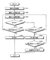
次に、図7〜図10を参照して、人(補助者など)が機体2に接近している場合における機体2の走行停止制御を例に、自動で異常を回避するための処理手順について説明する。図7〜図10は、走行停止制御の処理手順を示すフローチャートである。なお、図7〜図10に示す処理は、制御部100が各部を制御して実行する。
Next, with reference to FIGS. 7 to 10, the processing procedure for automatically avoiding an abnormality will be described by taking as an example the running stop control of the
まず、図7を参照して、走行停止制御の第1の例の処理手順について説明する。図7に示すように、ドローン20に搭載されたカメラ22で機体2周辺を撮影する(ステップS101)。
First, the processing procedure of the first example of the traveling stop control will be described with reference to FIG. 7. As shown in FIG. 7, the
制御部100は、カメラ22で撮影された画像を取得し、取得した画像を表示部12の表示画面121にリアルタイムで表示させる(ステップS102)。また、制御部100は、カメラ22で撮影された画像を表示部12に表示させる他、カメラ22で撮影された画像を解析する(ステップS103)。なお、かかる画像解析では、たとえば、形状判定を行い、判定結果に基づいて機体2周辺の人を認識するとともに、機体2周辺の人が認識された場合には機体2からの距離を測定する。
The
次いで、制御部100は、機体2が走行中であるか否かを判定する(ステップS104)。ステップS104の処理において、機体2が走行中であると判定された場合(ステップS104:Yes)、人が機体2から所定距離以内にいるか否かを判定する(ステップS105)。ステップS105の処理において、人が機体2から所定距離以内にいると判定された場合は(ステップS105:Yes)、走行装置3を駆動制御することで、機体2の走行を停止する(ステップS106)。機体2の走行停止については、たとえば、主変速レバーを中立位置に移動させる、すなわち、無段変速装置(HST)のトラニオン軸を中立位置に移動させる。これにより、機体2の走行が停止する。また、機体2を走行停止する場合、エンジンEを緊急停止する制御を行うようにしてもよい。
Next, the
なお、制御部100は、ステップS104の処理において、機体2が走行中ではないと判定された場合(ステップS104:No)は、ステップS103の処理に戻る。また、制御部100は、ステップS105の処理において、人が機体2から所定距離以内にいない場合(ステップS105:No)においても、ステップS103の処理に戻る。
If the
かかる構成によれば、機体2の走行中あるいは作業中、機体2周辺において異常が発生した場合には自動で異常を回避することができる。たとえば、補助者などの人が機体2に接近している場合、自動で機体2の走行を停止することで、人との接触を防止することができる。これにより、安全性を向上させる。また、回避操作を自動で行うため、作業者の手間を省くことができ、作業性の低下を抑えることができる。
According to such a configuration, if an abnormality occurs in the vicinity of the
次に、図8を参照して、走行停止制御の第2の例の処理手順について説明する。なお、図8を用いて説明する第2の例は、上記した第1の例とは警報を発生させる処理(ステップS206)を含む点で異なる。すなわち、第2の例における処理のうち、ステップS201〜ステップS205の処理は、第1の例におけるステップS101〜ステップS105の処理と同様である。また、第2の例におけるステップS207の処理は、第1の例におけるステップS106の処理と同様である。このため、第2の例においては、第1の例との相違点のみを説明する。 Next, the processing procedure of the second example of the traveling stop control will be described with reference to FIG. The second example described with reference to FIG. 8 is different from the first example described above in that it includes a process for generating an alarm (step S206). That is, among the processes in the second example, the processes in steps S201 to S205 are the same as the processes in steps S101 to S105 in the first example. Further, the process of step S207 in the second example is the same as the process of step S106 in the first example. Therefore, in the second example, only the differences from the first example will be described.
図8に示すように、制御部100は、ステップS206の処理において、人が機体2から所定距離以内にいると判定された場合は(ステップS205:Yes)、警報部14(図5参照)にブザー音などの警報を発生させる(ステップS206)。そして、制御部100は、機体2の走行を停止する(ステップS207)。
As shown in FIG. 8, when it is determined in the process of step S206 that a person is within a predetermined distance from the aircraft 2 (step S205: Yes), the
かかる構成によれば、機体2の走行中、機体2から所定距離以内に補助者などの人がいる場合には機体2が自動で停止するため、機体2と人との接触などを防ぐことができ、安全性を向上させることができる。たとえば、補助者などの人が機体2に接近している場合、警報を発生させることで、人に危険を認識させることができ、自動で機体2の走行を停止することで、人との接触を防止することができる。これにより、安全性を向上させる。
According to this configuration, if there is a person such as an assistant within a predetermined distance from the
また、回避操作を自動で行うため、作業者の手間を省くことができ、作業性の低下を抑えることができる。 In addition, since the avoidance operation is automatically performed, the labor of the operator can be saved and the deterioration of workability can be suppressed.
なお、上記した第2の例においては、警報を発生させ、かつ、機体2の走行を停止する構成としているが、警報を発生させるだけの構成としてもよい。このように構成しても、機体2の走行中、機体2から所定距離以内に補助者などの人がいる場合に警報が発生するため、機体2の近くに人がいるのを作業者が把握することができるとともに、人に危険を認識させることで、人との接触を防止することができ、安全性を向上させることができる。
In the second example described above, the configuration is such that an alarm is generated and the traveling of the
次に、図9を参照して、走行停止制御の第3の例の処理手順について説明する。なお、図9を用いて説明する第3の例は、上記した第1の例のステップS104の処理において機体2が走行中でないと判定された場合の処理を追加した点で第1の例とは異なる。すなわち、第3の例における処理のうち、ステップS301〜ステップS306の処理は、第1の例におけるステップS101〜ステップS106の処理と同様である。このため、第3の例においては、第1の例との相違点のみを説明する。
Next, the processing procedure of the third example of the traveling stop control will be described with reference to FIG. The third example described with reference to FIG. 9 is different from the first example in that a process when it is determined that the
図9に示すように、制御部100は、ステップS304の処理において、機体2が走行中ではないと判定された場合(ステップS304:No)は、人が機体2から所定距離以内にいるか否かを判定する(ステップS307)。制御部100は、ステップS307の処理において、人が機体2から所定距離以内にいると判定された場合は(ステップS307:Yes)、作業者による走行操作を無効にする(ステップS308)。走行操作の無効については、たとえば、主変速装置と無段変速装置との間の電気的接続を遮断する制御を行うことで、作業者による主変速レバーの操作を受け付けない。
As shown in FIG. 9, when the
なお、制御部100は、ステップS307の処理において、人が機体2から所定距離以内にいない場合(ステップS307:No)は、ステップS303の処理に戻る。
In addition, in the process of step S307, when the person is not within a predetermined distance from the machine body 2 (step S307: No), the
かかる構成によれば、機体2の停止中、機体2に人が接近している場合には作業者による機体2の走行操作を無効にすることで、人との接触を防止することができ、安全性を向上させることができる。
According to such a configuration, when a person is approaching the
ここで、制御部100は、人の機体2からの距離に応じた複数の閾値を設け、複数の閾値ごとに機体2の走行条件を設定してもよい。すなわち、制御部100は、人が機体2に近いほど走行条件が厳しくなるよう機体2の走行を規制する。制御部100は、たとえば、3つの閾値を設け、機体2から所定距離以内に人がいる場合には、機体2から最も遠い第1の閾値では、走行を制限しない。また、制御部100は、機体2から遠い第2の閾値では、走行速度を低速のみに制限(減速)する。また、制御部100は、機体に最も近い第3の閾値では、走行を停止する。
Here, the
かかる構成によれば、機体2の走行中、機体2から所定距離以内に補助者などの人がいる場合、機体2に対する人の接近に応じて、制限なし、減速、停止などのように段階的に機体2を停止するため、停止するまでもない安全な距離に人がいる場合などにおける走行停止を抑えて、安全性を確保しつつ作業性の低下を抑えることができる。
According to such a configuration, when there is a person such as an assistant within a predetermined distance from the
次に、図10を参照して、走行停止制御の第4の例の処理手順について説明する。なお、図10を用いて説明する第4の例は、上記した第3の例とは停止解除スイッチ13a(図5参照)による停止解除処理を含む点で異なる。すなわち、第4の例における処理のうち、ステップS401〜ステップS408の処理は、第3の例におけるステップS301〜ステップS308の処理と同様である。このため、第4の例においては、第3の例との相違点のみを説明する。 Next, the processing procedure of the fourth example of the traveling stop control will be described with reference to FIG. The fourth example described with reference to FIG. 10 is different from the third example described above in that it includes a stop release process by the stop release switch 13a (see FIG. 5). That is, among the processes in the fourth example, the processes in steps S401 to S408 are the same as the processes in steps S301 to S308 in the third example. Therefore, in the fourth example, only the differences from the third example will be described.
図10に示すように、制御部100は、走行操作を無効にした後、たとえば操縦席5b付近に設けられた停止解除スイッチ13aの操作を検知する(ステップS409)。停止解除スイッチ13aの操作が検知されると(ステップS409:Yes)、走行装置3を駆動制御して低速走行のみ許可する。なお、制御部100は、ステップS409の処理において、停止解除スイッチ13aの操作が検知されない場合(ステップS409:No)は、走行操作の無効を継続する。
As shown in FIG. 10, after disabling the traveling operation, the
かかる構成によれば、作業者が安全を確認してから機体2を元の状態(走行可能な状態)に復帰させるようになるため、安全性を確保することができる。機体2を復帰させる場合には機体2の走行が低速に規制されるため、安全性を確保することができる。
According to such a configuration, the safety can be ensured because the operator returns the
なお、制御部100は、停止解除スイッチ13aの操作により、低速走行のみ許可する構成としているが、走行速度をとくに制限しない構成としてもよい。このように構成しても、作業者が安全を確認してから機体2を元の状態に復帰させるようになるため、安全性を確保することができる。
Although the
また、ドローン20が圃場Fの上空を飛行しながらカメラ22で撮影した画像を、刈り取り作業などの作業性の向上のために活用することも可能である。
It is also possible to utilize the image taken by the
次に、図11および図12を参照して、圃場Fごとの最適ルートR表示制御について説明する。図11は、最適ルートR表示の説明図である。なお、図11には、最適ルートRが表示された状態の表示部12aを例示している。また、図12は、最適ルートR表示制御の処理手順を示すフローチャートである。
Next, the optimum route R display control for each field F will be described with reference to FIGS. 11 and 12. FIG. 11 is an explanatory diagram of the optimum route R display. Note that FIG. 11 illustrates a
制御部100は、カメラ22で撮影された圃場Fの上空画像をマップ化する処理を実行し、圃場Fのマップデータと、機体2の型式や性能を示すパラメータとに基づいて、圃場Fにおける最適ルートRを表示部12aの表示画面に表示させる。たとえば、図11に示すように、表示画面には、圃場Fを出入口Faから反時計まわりに回りながら穀稈を刈り取る、左まわりの回り刈りのルートが最適ルートRとして表示される。
The
図12に示すように、制御部100は、カメラ22で撮影された画像を取得し、取得した画像をマップ化する(ステップS501)。次いで、制御部100は、マップデータと機体2のパラメータとに基づいて、最適ルートRを決定し(ステップS502)、決定された最適ルートRを表示部12aの表示画面に表示させる(ステップS503)。
As shown in FIG. 12, the
かかる構成によれば、圃場Fごとに機体2のパラメータに応じて最適ルートRが表示されるため、たとえば、これから刈り取り作業を始める圃場における作業に要する時間などを作業者が大まかに把握することができる。これにより、熟練者ではない経験の浅い作業者でも、効率良く作業を行うことができ、作業性を向上させることができる。
According to this configuration, the optimum route R is displayed for each field F according to the parameters of the
次に、図13および図14を参照して、圃場Fごとの注意ポイントP表示制御について説明する。図13は、注意ポイントP表示の説明図である。なお、図13には、注意ポイントPが表示された状態の表示部12aを例示している。また、図14は、注意ポイントP表示制御の処理手順を示すフローチャートである。
Next, with reference to FIGS. 13 and 14, the caution point P display control for each field F will be described. FIG. 13 is an explanatory diagram of the caution point P display. Note that FIG. 13 illustrates a
制御部100は、カメラ22で撮影された圃場Fの上空画像をマップ化する処理を実行し、圃場Fのマップデータと、機体2の型式や性能を示すパラメータとに基づいて、圃場Fにおける注意ポイントP、すなわち、圃場Fにおいて気を付けるべき箇所を表示部12aの表示画面に表示させる。
The
図14に示すように、制御部100は、カメラ22で撮影された画像を取得し、取得した画像をマップ化する(ステップS601)。次いで、制御部100は、マップデータと機体2のパラメータとに基づいて、注意ポイントPを判定し(ステップS602)、判定された注意ポイントPを表示部12aの表示画面に表示させる(ステップS603)。
As shown in FIG. 14, the
次いで、制御部100は、機体2が作業を開始すると、機体2が注意ポイントPに近いか否かを検知し(ステップS604)、機体2が注意ポイントに近いことが検知されると(ステップS604:Yes)、警報部14(図5参照)に警報を発生させる。なお、ステップS604の処理において、機体2が注意ポイントPに近いことが検知されない場合は(ステップS604:No)、注意ポイントPに近いことが検知されるまで処理を繰り返す。
Next, when the
かかる構成によれば、圃場Fごとに機体2のパラメータに応じて圃場Fにおける注意ポイントPが表示されるため、経験の浅い作業者でも、注意ポイントPを把握することができるとともに、注意ポイントPを回避して作業することができ、作業中のトラブルを未然に防いで効率良く作業を行うことができる。これにより、作業性を向上させることができる。
According to this configuration, since the caution point P in the field F is displayed for each field F according to the parameter of the
また、ドローン20が圃場Fの上空を飛行しながらカメラ22で撮影した画像や機体2周辺の画像を、作業者の操作評価に用いることも可能である。この場合、切り株Gb(図6参照)の状態、すなわち、穀稈の刈り跡から機体2の直進操作性や刈り取りの正確性を評価するようにしてもよい。これにより、作業後の機体2の状態からわかる燃費や負荷率などの測定だけでなく、作業中あるいは作業後の圃場Fの状態で操作評価を行うことができ、より正確な操作評価を行うことができる。また、営農の場合は、経営者が従業員の評価に用いることも可能である。
It is also possible to use the image taken by the
次に、図15を参照してコンバインの制御システムの変形例(制御システム1A)について説明する。図15は、コンバインの制御システムの変形例(制御システム1A)の説明図である。なお、図15には、圃場Fを走行している機体2と、機体2に先行して飛行しているドローン20とを概略左側面視で示し、図中において機体2およびドローン20の進行方向をそれぞれ矢線で示している。
Next, a modified example of the combine control system (
図15に示すように、刈り取り作業において圃場Fが乾燥している場合、機体2に先行して飛行しているドローン20によって、機体2の前進にあわせて機体2の前方に向けて上空から水を噴射するように構成してもよい。この場合、ドローン20には、噴射する水を貯留するタンクが設けられる。かかる構成によれば、圃場F面を湿らせて刈り取り作業中の埃の発生を抑えることができる。
As shown in FIG. 15, when the field F is dry in the mowing operation, the
また、機体2側にも水を貯留するタンクが設けられ、ドローン20のタンクに補給するように構成してもよい。また、機体2側に充電装置が設けられ、ドローン20を機体2側において充電可能に構成してもよい。かかる構成によれば、水やバッテリーを機体2側で補給することができ、連続作業が可能となる。
Further, a tank for storing water may be provided on the side of the
また、ドローン20に照明装置が設けられ、機体2に先行して飛行しているドローン20によって、たとえば、機体2の前方を照らす構成としてもよい。かかる構成によれば、夜間作業において効率的に圃場を照らすことができる。なお、GPSなどの受信アンテナ6を機体2およびドローン20の双方に設けることで、機体2に対するドローン20の飛行経路を任意に設定することができる。
Further, the
なお、制御部100において、ドローン20の不使用時には、ドローン20を貯留装置4Cの上面に移動させて駐機させるよう制御する構成としてもよい。この場合、貯留装置4Cの上面に固定手段を設け、ドローン20を固定手段によって貯留装置4Cの上面に固定する。かかる構成によれば、ドローン20が、脱穀装置4Bの扱胴カバーの開閉や排出装置4Dの旋回を妨げない。
The
また、制御部100において、HSTレバーが後進側に操作されたことが検知されると、ドローン20を機体2の後方に位置させてカメラ22をバックモニタとして機能させるように制御する構成としてもよい。かかる構成によれば、作業者が機体2後方を表示部12の表示画面121で確認することができ、安全性を向上させることができる。
Further, when the
また、制御部100において、刈り取り作業中にはドローン20を機体2の上方に位置させてカメラ22で機体2の平面視の画像を撮影するように制御する構成としてもよい。かかる構成によれば、操縦席5bから見えにくい機体2の左側なども作業者が確認することができ、たとえば、補助者などの人がいる場合には回避操作を行うことができるため、安全を確保することができる。
Further, the
(収穫作業システム)
上述の制御部100には、無人飛行体20に備えた測位装置21と同様の測位装置が備えられる。(RTK方式のものが好ましい。)また、記憶装置152には、圃場の形状と、この形状に基づいて設定された走行経路が記憶されており、コンバイン2は、刈取装置4A、脱穀装置4B等の作業装置を駆動しながら、この走行経路に沿って自動走行する。
(Harvesting work system)
The
無人飛行体20のコントローラ200には、圃場の形状と、この形状に基づいて設定された飛行経路(高度を含む)が記憶されており、無人飛行体20は、この飛行経路に沿って飛行する。また、レーダ23によってコンバイン2との距離を測定することができ、コ
ンバイン2と一定の距離を維持しながら飛行することができる。
The controller 200 of the unmanned flying
無人飛行体20に備えたカメラ22による撮影情報は、無人飛行体20側のコントローラ200からコンバイン2側へ送信される。コンバイン2側では、この撮影情報を機体制御部150で受信する。
The shooting information taken by the
これにより、無人飛行体20をコンバイン2よりも先行する位置に飛行させ、カメラ22によって圃場の植立穀稈を撮影し、この撮影情報から植立穀稈の倒伏状態を検出し、この倒伏状態に応じてコンバイン2の作業走行速度を変速制御する。
As a result, the unmanned flying
また、カメラ22による撮影情報から圃場内の複数領域での植立穀稈の倒伏状態を検出し、この倒伏状態に応じてコンバイン2の作業走行速度を各領域ごとに変速制御する。
Further, the lodging state of the planted culm in a plurality of regions in the field is detected from the information captured by the
また、無人飛行体20をコンバイン2よりも先行する位置に飛行させ、カメラ22によって圃場の植立穀稈を撮影し、この撮影情報から植立穀稈の倒伏状態を検出し、この倒伏状態に応じてコンバイン2の刈取装置4Aを圃場面近傍の高さに位置付ける。
In addition, the unmanned flying
また、無人飛行体20に備えたカメラ22によってコンバイン2と圃場を同時に撮影し、この撮影情報からコンバイン2の走行方向が設定された走行経路に対してずれていることが検出された場合に、コンバイン2を設定された走行経路に復帰させる操向制御がなされる。
Further, when the
また、無人飛行体20に備えたカメラ22によってコンバイン2と圃場を同時に撮影し、この撮影情報からコンバイン2の前方に障害物があることが検出された場合に、コンバイン2の走行と刈取装置4Aの駆動を自動的に停止させる。
Further, when the
また、無人飛行体20に備えたカメラ22によってコンバイン2と圃場を同時に撮影し、この撮影情報からコンバイン2の前方に障害物があることが判定された場合に、この障害物を回避するように走行経路を新たに生成し、この走行経路に沿ってコンバイン2を自動的に操向する。障害物を回避した後、元の設定経路に復帰するように操向される。
Further, when the
(別実施例1)
コンバイン2を自動走行させるべく設定された走行経路のうち、最外周の走行経路から、収穫作業を行う圃場面積を算出し、この圃場面積とコンバイン2の平均車速から、その圃場での収穫作業に要する時間を算出して送信し、情報処理端末10の表示部12または圃場脇で監視している作業者の携帯端末に、収穫作業が終了する予測時刻を表示するように構成してもよい。
(Another Example 1)
Of the travel routes set to automatically drive the
また、上述のようにして、圃場面積とコンバイン2Cの平均車速から、貯留装置4Cが満杯になるまでの時間を算出して送信し、情報処理端末10の表示部12または圃場脇で監視している作業者の携帯端末に、穀粒排出作業が必要となる予測時刻を表示するように構成してもよい。
Further, as described above, the time until the
(別実施例2)
コンバイン2を設定された走行経路に沿って自動走行させた場合、刈取装置4Aが穀稈の株に突っ込んで所謂「株割り」を生じ、穀稈を押し倒して刈残すことが起こりうる。
(Another Example 2)
When the
これに対処するために、刈取装置4Aを機体フレームに対して左右方向に移動自在に支持し、植立穀稈との接触によってON/OFFする倣いセンサを設け、この倣いセンサの検出結果に基づいて電動モータ等の駆動装置を作動させ、刈取装置4Aを左右方向に移動させる構成としてもよい。
In order to deal with this, the
この構成によって、コンバイン2を設定された走行経路に沿って自動走行させながら、刈取装置4Aを隣接する穀稈列の間に常時位置するように左右方向に移動制御し、株割りを防ぐことができる。
With this configuration, it is possible to prevent stock splitting by controlling the movement of the
また、刈取装置4Aを左右方向に移動させる駆動装置を、手動操作具の操作によって作動させる構成とし、操縦席5bに着座した操縦者の手が届く位置に、この手動操作具を配置してもよい。なお、この手動操作具は、操縦席5bの左側に配置するのが好ましい。
Further, even if the drive device for moving the
(別実施例3)
この収穫作業システムに使用するコンバイン2を、小型コンバイン(2条刈コンバイン)または中型コンバイン(4条刈コンバイン)と、大型コンバイン(6条刈コンバイン)の2台とし、小型コンバインまたは中型コンバインに圃場の外周領域を収穫走行する経路を設定し、大型コンバインに圃場の外周領域以外の領域を収穫走行する経路を設定する。これにより、小型または中型のコンバインによって圃場の外周領域を収穫走行させることで、畦際でのトラブルを起こしにくく、走行装置によって圃場面を荒らすことが少なくなる。また、小型または中型のコンバインは、最初の圃場の外周領域を収穫走行した後、次の圃場に移動してその圃場の外周領域を収穫走行させる。大型コンバイは、最初の圃場の外周領域以外の領域を収穫走行した後、次の圃場の外周領域以外の領域を収穫走行する。すなわち、小型または中型のコンバインと大型コンバインとで、圃場における収穫走行領域を分担することで、収穫作業の能率向上が図れる。
(Another Example 3)
The
(参考例1)
脱穀装置4Bの選別部に備えたシーブの角度を電動モータで制御する構成とし、貯留装置4C内の上部に設けたカメラで貯留装置4Cに投入される1番物中の稈切れや枝梗粒の量を検出し、この量が多い場合に電動モータを作動させてシーブを閉じるように制御する構成としてもよい。
(Reference example 1)
The angle of the sheave provided in the sorting section of the threshing
これによって、貯留装置4Cに投入される稈切れや枝梗粒を減らすことができる。
As a result, it is possible to reduce the number of culms and branch stalks charged into the
(参考例2)
脱穀装置4Bの選別部に備えた唐箕の風量を、電動モータで制御する構成とし、貯留装置4C内の上部に設けたカメラで貯留装置4Cに投入される1番物中の稈切れや枝梗粒の量を検出し、この量が多い場合に電動モータを作動させて唐箕風量を増加させ、この量が少ない場合には唐箕風量を減少させるように制御する構成としてもよい。
(Reference example 2)
The air volume of the wall insert provided in the sorting section of the threshing
これによって、貯留装置4Cに投入される稈切れや枝梗粒を減らすことができる。
As a result, it is possible to reduce the number of culms and branch stalks charged into the
(参考例3)
脱穀装置4Bの脱穀室の上部に備えた送塵弁の角度を、電動モータで制御する構成とし、貯留装置4C内の上部に設けたカメラで貯留装置4Cに投入される1番物中の稈切れや枝梗粒や損傷粒の量を検出し、この量が多い場合に電動モータを作動させて送塵弁の角度を送り方向側に制御し、この量が少ない場合には送塵弁の角度を抵抗側に制御する構成としてもよい。
(Reference example 3)
The angle of the dust feed valve provided in the upper part of the threshing chamber of the threshing
これによって、貯留装置4Cに投入される稈切れや枝梗粒や損傷粒を減らすことができる。
As a result, it is possible to reduce the number of culm, branch stalk grains and damaged grains that are charged into the
(参考例4)
脱穀装置4Bの選別部に備えた唐箕の風量を、電動モータで制御する構成とし、貯留装置4C内に投入される穀粒の水分量を検出する水分センサを設け、この水分量が多いほど唐箕の風量を増加させるように制御する構成としてもよい。
(Reference example 4)
The air volume of the wall insert provided in the sorting section of the threshing
これによって、貯留装置4Cへの藁屑の投入を減少させることができる。
This makes it possible to reduce the amount of straw waste charged into the
さらなる効果や変形例は、当業者によって容易に導き出すことができる。このため、本発明のより広範な態様は、以上のように表しかつ記述した特定の詳細および代表的な実施形態に限定されるものではない。したがって、添付の特許請求の範囲およびその均等物によって定義される総括的な発明の概念の精神または範囲から逸脱することなく、様々な変更が可能である。 Further effects and variations can be easily derived by those skilled in the art. For this reason, the broader aspects of the invention are not limited to the particular details and representative embodiments expressed and described above. Therefore, various modifications can be made without departing from the spirit or scope of the general concept of the invention as defined by the appended claims and their equivalents.
2 コンバイン
4A 刈取装置
20 無人飛行体
22 カメラ
100 制御部
200 コントローラ(制御部)
2
Claims (7)
前記カメラで撮影された映像により、前記コンバインの機体の周辺に人の存在を認識した場合に前記機体の走行を停止させ、この走行停止状態において前記コンバインの操縦席の作業者が停止解除操作を行うことで、前記機体を走行可能な状態に復帰させることを特徴とする収穫作業システム。 It is a harvesting work system composed of a combine and an unmanned vehicle, and the combine receives information from the unmanned vehicle and automatically travels the aircraft along a travel route set in the field. A control unit for performing harvesting work is provided, and the unmanned vehicle is provided with information taken by a camera provided on the combine to be transmitted to the combine, and is set for a flight path set over the field or the combine's aircraft. a control unit for flying position,
When the presence of a person is recognized in the vicinity of the combine harvester based on the image taken by the camera, the vehicle is stopped from traveling, and in this traveling stopped state, the operator in the cockpit of the combine performs a stop release operation. A harvesting work system characterized by returning the machine to a state in which it can run.
Priority Applications (1)
| Application Number | Priority Date | Filing Date | Title |
|---|---|---|---|
| JP2018145894A JP6958508B2 (en) | 2018-08-02 | 2018-08-02 | Harvesting work system |
Applications Claiming Priority (1)
| Application Number | Priority Date | Filing Date | Title |
|---|---|---|---|
| JP2018145894A JP6958508B2 (en) | 2018-08-02 | 2018-08-02 | Harvesting work system |
Publications (2)
| Publication Number | Publication Date |
|---|---|
| JP2020018255A JP2020018255A (en) | 2020-02-06 |
| JP6958508B2 true JP6958508B2 (en) | 2021-11-02 |
Family
ID=69589066
Family Applications (1)
| Application Number | Title | Priority Date | Filing Date |
|---|---|---|---|
| JP2018145894A Active JP6958508B2 (en) | 2018-08-02 | 2018-08-02 | Harvesting work system |
Country Status (1)
| Country | Link |
|---|---|
| JP (1) | JP6958508B2 (en) |
Cited By (1)
| Publication number | Priority date | Publication date | Assignee | Title |
|---|---|---|---|---|
| WO2025229779A1 (en) * | 2024-04-30 | 2025-11-06 | 株式会社クボタ | Work vehicle |
Families Citing this family (77)
| Publication number | Priority date | Publication date | Assignee | Title |
|---|---|---|---|---|
| US11653588B2 (en) | 2018-10-26 | 2023-05-23 | Deere & Company | Yield map generation and control system |
| US11178818B2 (en) | 2018-10-26 | 2021-11-23 | Deere & Company | Harvesting machine control system with fill level processing based on yield data |
| US11589509B2 (en) | 2018-10-26 | 2023-02-28 | Deere & Company | Predictive machine characteristic map generation and control system |
| US11957072B2 (en) | 2020-02-06 | 2024-04-16 | Deere & Company | Pre-emergence weed detection and mitigation system |
| US11079725B2 (en) | 2019-04-10 | 2021-08-03 | Deere & Company | Machine control using real-time model |
| US11240961B2 (en) | 2018-10-26 | 2022-02-08 | Deere & Company | Controlling a harvesting machine based on a geo-spatial representation indicating where the harvesting machine is likely to reach capacity |
| US11467605B2 (en) | 2019-04-10 | 2022-10-11 | Deere & Company | Zonal machine control |
| US11672203B2 (en) | 2018-10-26 | 2023-06-13 | Deere & Company | Predictive map generation and control |
| US12069978B2 (en) | 2018-10-26 | 2024-08-27 | Deere & Company | Predictive environmental characteristic map generation and control system |
| US11641800B2 (en) | 2020-02-06 | 2023-05-09 | Deere & Company | Agricultural harvesting machine with pre-emergence weed detection and mitigation system |
| US11778945B2 (en) | 2019-04-10 | 2023-10-10 | Deere & Company | Machine control using real-time model |
| US11234366B2 (en) | 2019-04-10 | 2022-02-01 | Deere & Company | Image selection for machine control |
| KR20220027811A (en) * | 2019-06-28 | 2022-03-08 | 가부시끼 가이샤 구보다 | Automatic driving system, agricultural equipment, program, recording medium and method recording the program |
| US12329148B2 (en) | 2020-02-06 | 2025-06-17 | Deere & Company | Predictive weed map and material application machine control |
| US12035648B2 (en) | 2020-02-06 | 2024-07-16 | Deere & Company | Predictive weed map generation and control system |
| US12225846B2 (en) | 2020-02-06 | 2025-02-18 | Deere & Company | Machine control using a predictive map |
| US11477940B2 (en) | 2020-03-26 | 2022-10-25 | Deere & Company | Mobile work machine control based on zone parameter modification |
| JP7547088B2 (en) * | 2020-06-02 | 2024-09-09 | ヤンマーホールディングス株式会社 | Combine harvester and method for creating a running route |
| JP7542383B2 (en) * | 2020-09-30 | 2024-08-30 | 株式会社クボタ | Harvesting Machine |
| US11845449B2 (en) | 2020-10-09 | 2023-12-19 | Deere & Company | Map generation and control system |
| US11889788B2 (en) | 2020-10-09 | 2024-02-06 | Deere & Company | Predictive biomass map generation and control |
| US11474523B2 (en) | 2020-10-09 | 2022-10-18 | Deere & Company | Machine control using a predictive speed map |
| US12069986B2 (en) | 2020-10-09 | 2024-08-27 | Deere & Company | Map generation and control system |
| US11874669B2 (en) | 2020-10-09 | 2024-01-16 | Deere & Company | Map generation and control system |
| US11983009B2 (en) | 2020-10-09 | 2024-05-14 | Deere & Company | Map generation and control system |
| US11849672B2 (en) | 2020-10-09 | 2023-12-26 | Deere & Company | Machine control using a predictive map |
| US11675354B2 (en) | 2020-10-09 | 2023-06-13 | Deere & Company | Machine control using a predictive map |
| US12422847B2 (en) | 2020-10-09 | 2025-09-23 | Deere & Company | Predictive agricultural model and map generation |
| US11650587B2 (en) | 2020-10-09 | 2023-05-16 | Deere & Company | Predictive power map generation and control system |
| US12013245B2 (en) | 2020-10-09 | 2024-06-18 | Deere & Company | Predictive map generation and control system |
| US11711995B2 (en) | 2020-10-09 | 2023-08-01 | Deere & Company | Machine control using a predictive map |
| US11864483B2 (en) | 2020-10-09 | 2024-01-09 | Deere & Company | Predictive map generation and control system |
| US11825768B2 (en) | 2020-10-09 | 2023-11-28 | Deere & Company | Machine control using a predictive map |
| US11592822B2 (en) | 2020-10-09 | 2023-02-28 | Deere & Company | Machine control using a predictive map |
| US11727680B2 (en) | 2020-10-09 | 2023-08-15 | Deere & Company | Predictive map generation based on seeding characteristics and control |
| US12178158B2 (en) | 2020-10-09 | 2024-12-31 | Deere & Company | Predictive map generation and control system for an agricultural work machine |
| US20220110238A1 (en) | 2020-10-09 | 2022-04-14 | Deere & Company | Machine control using a predictive map |
| US11946747B2 (en) | 2020-10-09 | 2024-04-02 | Deere & Company | Crop constituent map generation and control system |
| US11871697B2 (en) | 2020-10-09 | 2024-01-16 | Deere & Company | Crop moisture map generation and control system |
| US11844311B2 (en) | 2020-10-09 | 2023-12-19 | Deere & Company | Machine control using a predictive map |
| US11635765B2 (en) | 2020-10-09 | 2023-04-25 | Deere & Company | Crop state map generation and control system |
| US20220110258A1 (en) | 2020-10-09 | 2022-04-14 | Deere & Company | Map generation and control system |
| US12386354B2 (en) | 2020-10-09 | 2025-08-12 | Deere & Company | Predictive power map generation and control system |
| US11895948B2 (en) | 2020-10-09 | 2024-02-13 | Deere & Company | Predictive map generation and control based on soil properties |
| US11849671B2 (en) | 2020-10-09 | 2023-12-26 | Deere & Company | Crop state map generation and control system |
| US12419220B2 (en) | 2020-10-09 | 2025-09-23 | Deere & Company | Predictive map generation and control system |
| US11927459B2 (en) | 2020-10-09 | 2024-03-12 | Deere & Company | Machine control using a predictive map |
| US11889787B2 (en) | 2020-10-09 | 2024-02-06 | Deere & Company | Predictive speed map generation and control system |
| US12250905B2 (en) | 2020-10-09 | 2025-03-18 | Deere & Company | Machine control using a predictive map |
| JP7041794B1 (en) * | 2020-11-27 | 2022-03-24 | 楽天グループ株式会社 | Sensing system, sensing data acquisition method, and control device |
| JP7718810B2 (en) | 2020-12-02 | 2025-08-05 | ヤンマーホールディングス株式会社 | Autonomous driving system, autonomous driving method, and autonomous driving program |
| JP2022092391A (en) * | 2020-12-10 | 2022-06-22 | 株式会社クボタ | Mobile vehicle |
| JP7174748B2 (en) * | 2020-12-18 | 2022-11-17 | 楽天グループ株式会社 | Travel control system, control method, and control device |
| JP7413250B2 (en) * | 2020-12-29 | 2024-01-15 | 株式会社クボタ | agricultural support system |
| AU2021412656A1 (en) | 2020-12-29 | 2023-07-06 | Kubota Corporation | Agricultural machine |
| EP4272525A4 (en) | 2020-12-29 | 2024-12-04 | Kubota Corporation | AGRICULTURAL ASSISTANCE SYSTEM AND UNMANNED AIRCRAFT |
| CN112815943B (en) * | 2020-12-31 | 2023-11-21 | 广州极飞科技股份有限公司 | Method and device for determining operation route of unmanned equipment and unmanned equipment |
| US12127500B2 (en) | 2021-01-27 | 2024-10-29 | Deere & Company | Machine control using a map with regime zones |
| JP7211443B2 (en) * | 2021-02-25 | 2023-01-24 | 井関農機株式会社 | running vehicle |
| JP7544666B2 (en) * | 2021-06-29 | 2024-09-03 | 株式会社クボタ | Cultivation machine control system and walking type cultivation machine |
| US12229886B2 (en) | 2021-10-01 | 2025-02-18 | Deere & Company | Historical crop state model, predictive crop state map generation and control system |
| CN114115338B (en) * | 2021-11-11 | 2023-11-14 | 河北英虎农业机械股份有限公司 | Corn harvesting method based on unmanned aerial vehicle cooperation |
| JP7755978B2 (en) * | 2021-11-24 | 2025-10-17 | 三菱マヒンドラ農機株式会社 | combine |
| US12310286B2 (en) | 2021-12-14 | 2025-05-27 | Deere & Company | Crop constituent sensing |
| US12302791B2 (en) | 2021-12-20 | 2025-05-20 | Deere & Company | Crop constituents, predictive mapping, and agricultural harvester control |
| US12245549B2 (en) | 2022-01-11 | 2025-03-11 | Deere & Company | Predictive response map generation and control system |
| CN114402995B (en) * | 2022-01-19 | 2023-03-24 | 北京市农林科学院智能装备技术研究中心 | Corn emasculation method, system and aerial unmanned emasculation machine coordinated by air and ground |
| US12520759B2 (en) | 2022-01-26 | 2026-01-13 | Deere & Company | Systems and methods for predicting material dynamics |
| US12082531B2 (en) | 2022-01-26 | 2024-09-10 | Deere & Company | Systems and methods for predicting material dynamics |
| US12295288B2 (en) | 2022-04-05 | 2025-05-13 | Deere &Company | Predictive machine setting map generation and control system |
| US12058951B2 (en) | 2022-04-08 | 2024-08-13 | Deere & Company | Predictive nutrient map and control |
| US12358493B2 (en) | 2022-04-08 | 2025-07-15 | Deere & Company | Systems and methods for predictive power requirements and control |
| US12284934B2 (en) | 2022-04-08 | 2025-04-29 | Deere & Company | Systems and methods for predictive tractive characteristics and control |
| US12298767B2 (en) | 2022-04-08 | 2025-05-13 | Deere & Company | Predictive material consumption map and control |
| JP2024013463A (en) * | 2022-07-20 | 2024-02-01 | ヤンマーホールディングス株式会社 | work vehicle |
| JP7726262B2 (en) * | 2023-12-25 | 2025-08-20 | 井関農機株式会社 | Harvesting machine travel path generation device |
| JP7691670B1 (en) * | 2025-04-06 | 2025-06-12 | 佑斗 井澤 | Machines and Systems |
Family Cites Families (6)
| Publication number | Priority date | Publication date | Assignee | Title |
|---|---|---|---|---|
| JP3812029B2 (en) * | 1997-01-28 | 2006-08-23 | 井関農機株式会社 | Depth control device for combine etc. |
| JPH11137062A (en) * | 1997-11-10 | 1999-05-25 | Yanmar Agricult Equip Co Ltd | General-purpose combine control unit |
| JP2000166357A (en) * | 1998-12-04 | 2000-06-20 | Iseki & Co Ltd | Lodging culm row detector |
| NL2012485B1 (en) * | 2014-03-20 | 2016-01-18 | Lely Patent Nv | Method and system for navigating an agricultural vehicle on a land area. |
| JP6755117B2 (en) * | 2016-04-26 | 2020-09-16 | ヤンマーパワーテクノロジー株式会社 | combine |
| JP2018042477A (en) * | 2016-09-12 | 2018-03-22 | 島根県 | Automatic reaping system |
-
2018
- 2018-08-02 JP JP2018145894A patent/JP6958508B2/en active Active
Cited By (1)
| Publication number | Priority date | Publication date | Assignee | Title |
|---|---|---|---|---|
| WO2025229779A1 (en) * | 2024-04-30 | 2025-11-06 | 株式会社クボタ | Work vehicle |
Also Published As
| Publication number | Publication date |
|---|---|
| JP2020018255A (en) | 2020-02-06 |
Similar Documents
| Publication | Publication Date | Title |
|---|---|---|
| JP6958508B2 (en) | Harvesting work system | |
| JP6958195B2 (en) | Combine control system | |
| JP7034866B2 (en) | Harvester | |
| JP7381402B2 (en) | automatic driving system | |
| JP7665001B2 (en) | Work management system and work management method | |
| CN113727597B (en) | Harvesters and other agricultural machinery | |
| JP2024015257A5 (en) | ||
| CN113766824B (en) | Harvester, obstacle judgment program, recording medium, obstacle judgment method | |
| JP2020178619A (en) | Agricultural work machine | |
| JP2022033302A (en) | Harvesting machine | |
| CN113923977A (en) | Automatic travel system, agricultural machine, program, recording medium having program recorded thereon, and method | |
| JP7109300B2 (en) | harvester | |
| JP7466276B2 (en) | Work vehicle coordination system | |
| JP7149897B2 (en) | harvester | |
| JP2022092391A (en) | Mobile vehicle | |
| JP2020072740A (en) | Combine | |
| JP2023160359A (en) | Aircraft control method, control program, and recording medium | |
| US20240016087A1 (en) | Combine and travel control method | |
| CN115599085A (en) | Work support system | |
| JP2022095324A (en) | Work vehicle | |
| US20260016830A1 (en) | Obstruction and remote attribute monitoring during an agricultural operation | |
| US20260016828A1 (en) | Remote header performance attribute monitoring during an agricultural operation | |
| US20260013412A1 (en) | Remote lateral attribute monitoring during an agricultural operation | |
| US20260017728A1 (en) | Remote job quality attribute monitoring during an agricultural operation | |
| US20260016827A1 (en) | Remote attribute monitoring during an agricultural operation based on obstruction |
Legal Events
| Date | Code | Title | Description |
|---|---|---|---|
| A621 | Written request for application examination |
Free format text: JAPANESE INTERMEDIATE CODE: A621 Effective date: 20200428 |
|
| A871 | Explanation of circumstances concerning accelerated examination |
Free format text: JAPANESE INTERMEDIATE CODE: A871 Effective date: 20201030 |
|
| A977 | Report on retrieval |
Free format text: JAPANESE INTERMEDIATE CODE: A971007 Effective date: 20210304 |
|
| A975 | Report on accelerated examination |
Free format text: JAPANESE INTERMEDIATE CODE: A971005 Effective date: 20210406 |
|
| A131 | Notification of reasons for refusal |
Free format text: JAPANESE INTERMEDIATE CODE: A131 Effective date: 20210413 |
|
| A521 | Request for written amendment filed |
Free format text: JAPANESE INTERMEDIATE CODE: A523 Effective date: 20210611 |
|
| TRDD | Decision of grant or rejection written | ||
| A01 | Written decision to grant a patent or to grant a registration (utility model) |
Free format text: JAPANESE INTERMEDIATE CODE: A01 Effective date: 20210907 |
|
| A61 | First payment of annual fees (during grant procedure) |
Free format text: JAPANESE INTERMEDIATE CODE: A61 Effective date: 20210920 |
|
| R150 | Certificate of patent or registration of utility model |
Ref document number: 6958508 Country of ref document: JP Free format text: JAPANESE INTERMEDIATE CODE: R150 |