[go: up one dir, main page]

JP6958504B2 - Rotating machine stator - Google Patents

Rotating machine stator Download PDF

Info

Publication number
JP6958504B2
JP6958504B2 JP2018139470A JP2018139470A JP6958504B2 JP 6958504 B2 JP6958504 B2 JP 6958504B2 JP 2018139470 A JP2018139470 A JP 2018139470A JP 2018139470 A JP2018139470 A JP 2018139470A JP 6958504 B2 JP6958504 B2 JP 6958504B2
Authority
JP
Japan
Prior art keywords
turn portion
phase
stator
turn
radial direction
Prior art date
Legal status (The legal status is an assumption and is not a legal conclusion. Google has not performed a legal analysis and makes no representation as to the accuracy of the status listed.)
Active
Application number
JP2018139470A
Other languages
Japanese (ja)
Other versions
JP2020018093A (en
Inventor
暁斗 田村
亜希 福原
Current Assignee (The listed assignees may be inaccurate. Google has not performed a legal analysis and makes no representation or warranty as to the accuracy of the list.)
Denso Corp
Original Assignee
Denso Corp
Priority date (The priority date is an assumption and is not a legal conclusion. Google has not performed a legal analysis and makes no representation as to the accuracy of the date listed.)
Filing date
Publication date
Application filed by Denso Corp filed Critical Denso Corp
Priority to JP2018139470A priority Critical patent/JP6958504B2/en
Priority to CN201980048856.7A priority patent/CN112470369B/en
Priority to PCT/JP2019/021178 priority patent/WO2020021844A1/en
Publication of JP2020018093A publication Critical patent/JP2020018093A/en
Application granted granted Critical
Publication of JP6958504B2 publication Critical patent/JP6958504B2/en
Active legal-status Critical Current
Anticipated expiration legal-status Critical

Links

Images

Classifications

    • HELECTRICITY
    • H02GENERATION; CONVERSION OR DISTRIBUTION OF ELECTRIC POWER
    • H02KDYNAMO-ELECTRIC MACHINES
    • H02K3/00Details of windings
    • H02K3/04Windings characterised by the conductor shape, form or construction, e.g. with bar conductors
    • H02K3/24Windings characterised by the conductor shape, form or construction, e.g. with bar conductors with channels or ducts for cooling medium between the conductors
    • HELECTRICITY
    • H02GENERATION; CONVERSION OR DISTRIBUTION OF ELECTRIC POWER
    • H02KDYNAMO-ELECTRIC MACHINES
    • H02K3/00Details of windings
    • H02K3/04Windings characterised by the conductor shape, form or construction, e.g. with bar conductors
    • H02K3/28Layout of windings or of connections between windings

Landscapes

  • Engineering & Computer Science (AREA)
  • Power Engineering (AREA)
  • Windings For Motors And Generators (AREA)
  • Iron Core Of Rotating Electric Machines (AREA)

Description

この明細書における開示は、回転電機の固定子に関する。 The disclosure herein relates to a stator of a rotating electric machine.

特許文献1は、効率の低下や発生トルクの低下を防止する目的で、回転電機の固定子巻線において、コイルエンドの長いものと短いものとを組み合わせて二相の巻線を形成した技術を開示している。 Patent Document 1 describes a technique for forming a two-phase winding by combining a long coil end and a short coil end in a stator winding of a rotary electric machine for the purpose of preventing a decrease in efficiency and a decrease in generated torque. It is disclosed.

特開昭61−224841号公報Japanese Unexamined Patent Publication No. 61-224841

従来技術の構成では、コイル同士の重なり部分において、コイルへの通電によって発生した熱がこもりやすく、コイルの温度が上昇しやすかった。コイルの温度が異常に上昇することで、コイルをなす導線の被膜に熱劣化が生じてコイルの絶縁性が低下するなどして、回転電機が正常に機能しなくなることが懸念される。上述の観点において、または言及されていない他の観点において、回転電機の固定子にはさらなる改良が求められている。 In the configuration of the prior art, the heat generated by energizing the coils tends to be trapped in the overlapping portion of the coils, and the temperature of the coils tends to rise. If the temperature of the coil rises abnormally, the coating of the conducting wire forming the coil deteriorates due to heat, and the insulation property of the coil deteriorates, so that there is a concern that the rotating electric machine does not function normally. Further improvements are required in the stator of the rotary electric machine in the above-mentioned viewpoint or in other viewpoints not mentioned.

開示される1つの目的は、放熱性能の高い回転電機の固定子を提供することにある。 One object disclosed is to provide a stator of a rotating electric machine having high heat dissipation performance.

ここに開示された回転電機の固定子は、円環状の固定子コア(52)と、絶縁被膜(82b)によって覆われた複数相の固定子巻線(51)とを備え、回転自在に支持された回転子(40)と同軸に配置された固定子(50)であって、固定子巻線は、回転子の磁石部(42)に対して径方向に対向している磁石対向部(83)と、磁石対向部よりも回転軸の軸方向外側において同相の磁石対向部同士を接続しているターン部(84)とを有し、軸方向の両側に設けられるターン部のうち、少なくとも一方は放熱促進ターン部(841)であって、放熱促進ターン部は、異相の放熱促進ターン部同士が軸方向に部分的に重なって設けられているとともに、磁石対向部に対して径方向に突出しており、軸方向に重なり合う異相の放熱促進ターン部のうち、軸方向において固定子コアに最も近い位置に設けられている最内層ターン部(841U)と、軸方向において最内層ターン部よりも固定子コアから遠い位置に設けられている外層ターン部(841V,841W)とを備え、最内層ターン部の径方向への突出量は、外層ターン部の径方向への突出量とは異なる突出量である。 The stator of a rotary electric machine disclosed herein includes an annular stator core (52) and a multi-phase stator winding (51) covered with an insulating coating (82b) and is rotatably supported. The stator (50) is arranged coaxially with the rotor (40), and the stator winding is a magnet facing portion (50) that is radially opposed to the rotor magnet portion (42). 83) and a turn portion (84) connecting the magnet facing portions having the same phase on the outer side of the rotation axis in the axial direction from the magnet facing portion, and at least among the turn portions provided on both sides in the axial direction. One is a heat dissipation promotion turn portion (841), and the heat dissipation promotion turn portion is provided so that the heat dissipation promotion turn portions having different phases partially overlap each other in the axial direction and in the radial direction with respect to the magnet facing portion. Of the different-phase heat dissipation promotion turn portions that protrude and overlap in the axial direction, the innermost layer turn portion (841U) provided at the position closest to the stator core in the axial direction and the innermost layer turn portion in the axial direction are larger than those of the innermost layer turn portion. The outer layer turn portion (841V, 841W) provided at a position far from the stator core is provided, and the radial protrusion amount of the innermost layer turn portion is different from the radial protrusion amount of the outer layer turn portion. The amount.

開示された回転電機の固定子によると、放熱促進ターン部をなす最内層ターン部と外層ターン部とにおいて、最内層ターン部の径方向への突出量は、外層ターン部の径方向への突出量とは異なる突出量である。このため、最内層ターン部の径方向への突出量と外層ターン部の径方向への突出量とが等しい場合に比べて、最内層ターン部と外層ターン部とが軸方向に重ならない部分を大きく確保し、空気中への放熱を促進することができる。したがって、最内層ターン部と外層ターン部との大部分が重なっている場合に比べて、空気との接触面積を大きく確保しやすく、最内層ターン部で発生した熱がこもりにくい。よって、放熱性能の高い回転電機の固定子を提供できる。 According to the stator of the rotary electric machine disclosed, in the innermost layer turn portion and the outer layer turn portion forming the heat dissipation promoting turn portion, the amount of radial protrusion of the innermost layer turn portion is the radial protrusion of the outer layer turn portion. The amount of protrusion is different from the amount. Therefore, as compared with the case where the radial protrusion amount of the innermost layer turn portion and the radial protrusion amount of the outer layer turn portion are equal, the portion where the innermost layer turn portion and the outer layer turn portion do not overlap in the axial direction is formed. It can be secured large and heat dissipation to the air can be promoted. Therefore, as compared with the case where most of the innermost layer turn portion and the outer layer turn portion overlap, it is easier to secure a large contact area with air, and the heat generated in the innermost layer turn portion is less likely to be trapped. Therefore, it is possible to provide a stator of a rotating electric machine having high heat dissipation performance.

この明細書における開示された複数の態様は、それぞれの目的を達成するために、互いに異なる技術的手段を採用する。請求の範囲およびこの項に記載した括弧内の符号は、後述する実施形態の部分との対応関係を例示的に示すものであって、技術的範囲を限定することを意図するものではない。この明細書に開示される目的、特徴、および効果は、後続の詳細な説明、および添付の図面を参照することによってより明確になる。 The disclosed aspects herein employ different technical means to achieve their respective objectives. The claims and the reference numerals in parentheses described in this section exemplify the correspondence with the parts of the embodiments described later, and are not intended to limit the technical scope. The objectives, features, and effects disclosed herein will be made clearer by reference to the subsequent detailed description and accompanying drawings.

回転電機の縦断面斜視図。Vertical cross-sectional perspective view of a rotary electric machine. 回転電機の縦断面図。Vertical sectional view of a rotary electric machine. 図2のIII−III線断面図。FIG. 2 is a cross-sectional view taken along the line III-III of FIG. 図3の一部を拡大して示す断面図。FIG. 3 is an enlarged cross-sectional view showing a part of FIG. 回転電機の分解図。Exploded view of the rotary electric machine. インバータユニットの分解図。Exploded view of the inverter unit. 固定子巻線のアンペアターンとトルク密度との関係を示すトルク線図。A torque diagram showing the relationship between the ampere-turn of the stator winding and the torque density. 回転子及び固定子の横断面図。Cross-sectional view of rotor and stator. 図8の一部を拡大して示す図。FIG. 8 is an enlarged view showing a part of FIG. 固定子の横断面図。Cross-sectional view of the stator. 固定子の縦断面図。Longitudinal section of the stator. 固定子巻線の斜視図。Perspective view of the stator winding. 導線の構成を示す斜視図。The perspective view which shows the structure of the conducting wire. 素線の構成を示す模式図。The schematic diagram which shows the structure of a wire. n層目における各導線の形態を示す図。The figure which shows the morphology of each conducting wire in the nth layer. n層目とn+1層目の各導線を示す側面図。The side view which shows each conductor of the nth layer and the n + 1th layer. 実施形態の磁石について電気角と磁束密度との関係を示す図。The figure which shows the relationship between the electric angle and the magnetic flux density about the magnet of an embodiment. 比較例の磁石について電気角と磁束密度との関係を示す図。The figure which shows the relationship between the electric angle and the magnetic flux density about the magnet of the comparative example. 回転電機の制御システムの電気回路図。Electrical circuit diagram of the control system of the rotary electric machine. 制御装置による電流フィードバック制御処理を示す機能ブロック図。The functional block diagram which shows the current feedback control processing by a control device. 制御装置によるトルクフィードバック制御処理を示す機能ブロック図。The functional block diagram which shows the torque feedback control processing by a control device. 第2実施形態における回転子及び固定子の横断面図。The cross-sectional view of the rotor and the stator in the second embodiment. 図22の一部を拡大して示す図。FIG. 22 is an enlarged view showing a part of FIG. 22. 磁石部における磁束の流れを具体的に示す図。The figure which shows concretely the flow of the magnetic flux in a magnet part. 別例における固定子の断面図。Cross-sectional view of the stator in another example. 別例における固定子の断面図。Cross-sectional view of the stator in another example. 別例における固定子の断面図。Cross-sectional view of the stator in another example. 別例における固定子の断面図。Cross-sectional view of the stator in another example. 別例においてn層目とn+1層目の各導線を示す側面図。In another example, a side view showing each lead wire of the nth layer and the n + 1th layer. 別例における固定子の断面図。Cross-sectional view of the stator in another example. 第1実施形態における回転電機の縦断面図。The vertical sectional view of the rotary electric machine in 1st Embodiment. 第1実施形態における固定子の斜視図。The perspective view of the stator in 1st Embodiment. 図32の一部を拡大して示す図。FIG. 32 is an enlarged view showing a part of FIG. 32. 第1実施形態における固定子の上面図。Top view of the stator in the first embodiment. 図34の一部を拡大して示す図。FIG. 34 is an enlarged view showing a part of FIG. 34.

図面を参照しながら、複数の実施形態を説明する。複数の実施形態において、機能的におよび/または構造的に対応する部分および/または関連付けられる部分には同一の参照符号、または百以上の位が異なる参照符号が付される場合がある。対応する部分および/または関連付けられる部分については、他の実施形態の説明を参照することができる。 A plurality of embodiments will be described with reference to the drawings. In a plurality of embodiments, functionally and / or structurally corresponding parts and / or related parts may be designated with the same reference code or reference codes having a hundreds or more different digits. For the corresponding and / or associated part, the description of other embodiments can be referred to.

(第1実施形態)
以下に、図1から図21を用いて、本実施形態に係る回転電機10の固定子50を適用可能な基礎的形態としての回転電機10を説明する。
(First Embodiment)
Hereinafter, the rotary electric machine 10 as a basic form to which the stator 50 of the rotary electric machine 10 according to the present embodiment can be applied will be described with reference to FIGS. 1 to 21.

本実施形態に係る回転電機10は、同期式多相交流モータであり、アウタロータ構造(外転構造)のものとなっている。回転電機10の概要を図1乃至図5に示す。図1は、回転電機10の縦断面斜視図であり、図2は、回転電機10の回転軸11に沿う方向での縦断面図であり、図3は、回転軸11に直交する方向での回転電機10の横断面図(図2のIII−III線断面図)であり、図4は、図3の一部を拡大して示す断面図であり、図5は、回転電機10の分解図である。なお、図3では、図示の都合上、回転軸11を除き、切断面を示すハッチングを省略している。以下の記載では、回転軸11が延びる方向を軸方向とし、回転軸11の中心から放射状に延びる方向を径方向とし、回転軸11を中心として円周状に延びる方向を周方向としている。 The rotary electric machine 10 according to the present embodiment is a synchronous multi-phase AC motor and has an outer rotor structure (abduction structure). The outline of the rotary electric machine 10 is shown in FIGS. 1 to 5. FIG. 1 is a vertical cross-sectional perspective view of the rotary electric machine 10, FIG. 2 is a vertical cross-sectional view of the rotary electric machine 10 in a direction along the rotation axis 11, and FIG. 3 is a vertical cross-sectional view in a direction orthogonal to the rotation axis 11. It is a cross-sectional view of the rotary electric machine 10 (cross-sectional view taken along line III-III in FIG. 2), FIG. 4 is an enlarged cross-sectional view of a part of FIG. 3, and FIG. 5 is an exploded view of the rotary electric machine 10. Is. In FIG. 3, for convenience of illustration, the hatching indicating the cut surface is omitted except for the rotating shaft 11. In the following description, the direction in which the rotating shaft 11 extends is the axial direction, the direction extending radially from the center of the rotating shaft 11 is the radial direction, and the direction extending radially around the rotating shaft 11 is the circumferential direction.

回転電機10は、大別して、軸受部20と、ハウジング30と、回転子40と、固定子50と、インバータユニット60とを備えている。これら各部材は、いずれも回転軸11と共に同軸上に配置され、所定順序で軸方向に組み付けられることで回転電機10が構成されている。 The rotary electric machine 10 is roughly classified into a bearing portion 20, a housing 30, a rotor 40, a stator 50, and an inverter unit 60. Each of these members is arranged coaxially with the rotating shaft 11 and is assembled in the axial direction in a predetermined order to form the rotating electric machine 10.

軸受部20は、軸方向に互いに離間して配置される2つの軸受21,22と、その軸受21,22を保持する保持部材23とを有している。軸受21,22は、例えばラジアル玉軸受であり、それぞれ外輪25と、内輪26と、それら外輪25及び内輪26の間に配置された複数の玉27とを有している。保持部材23は円筒状をなしており、その径方向内側に軸受21,22が組み付けられている。そして、軸受21,22の径方向内側に、回転軸11及び回転子40が回転自在に支持されている。 The bearing portion 20 has two bearings 21 and 22 arranged apart from each other in the axial direction, and a holding member 23 for holding the bearings 21 and 22. The bearings 21 and 22 are, for example, radial ball bearings, each of which has an outer ring 25, an inner ring 26, and a plurality of balls 27 arranged between the outer ring 25 and the inner ring 26. The holding member 23 has a cylindrical shape, and bearings 21 and 22 are assembled inside the holding member 23 in the radial direction. The rotating shaft 11 and the rotor 40 are rotatably supported inside the bearings 21 and 22 in the radial direction.

ハウジング30は、円筒状をなす周壁部31と、その周壁部31の軸方向両端部のうち一方の端部に設けられた端面部32とを有している。周壁部31の軸方向両端部のうち端面部32の反対側は開口部33となっており、ハウジング30は、端面部32の反対側が開口部33により全面的に開放された構成となっている。端面部32には、その中央に円形の孔34が形成されており、その孔34に挿通させた状態で、ネジやリベット等の固定具により軸受部20が固定されている。また、ハウジング30内、すなわち周壁部31及び端面部32により区画された内部スペースには、回転子40と固定子50とが収容されている。本実施形態では回転電機10がアウタロータ式であり、ハウジング30内には、筒状をなす回転子40の径方向内側に固定子50が配置されている。回転子40は、軸方向において端面部32の側で回転軸11に片持ち支持されている。 The housing 30 has a cylindrical peripheral wall portion 31 and end face portions 32 provided at one end of both axially end portions of the peripheral wall portion 31. Of both ends of the peripheral wall portion 31 in the axial direction, the opposite side of the end face portion 32 is an opening 33, and the housing 30 has a configuration in which the opposite side of the end face portion 32 is completely opened by the opening 33. .. A circular hole 34 is formed in the center of the end face portion 32, and the bearing portion 20 is fixed by a fixing tool such as a screw or a rivet in a state of being inserted into the hole 34. Further, the rotor 40 and the stator 50 are housed in the housing 30, that is, in the internal space partitioned by the peripheral wall portion 31 and the end face portion 32. In the present embodiment, the rotary electric machine 10 is an outer rotor type, and a stator 50 is arranged inside the housing 30 in the radial direction of the cylindrical rotor 40. The rotor 40 is cantilevered by the rotating shaft 11 on the side of the end face portion 32 in the axial direction.

回転子40は、中空筒状に形成された回転子本体41と、その回転子本体41の径方向内側に設けられた環状の磁石部42とを有している。回転子本体41は、略カップ状をなし、磁石保持部材としての機能を有する。回転子本体41は、筒状をなす磁石保持部43と、同じく筒状をなしかつ磁石保持部43よりも小径の固定部44と、それら磁石保持部43及び固定部44を繋ぐ部位となる中間部45とを有している。磁石保持部43の内周面に磁石部42が取り付けられている。 The rotor 40 has a rotor main body 41 formed in a hollow cylindrical shape, and an annular magnet portion 42 provided inside the rotor main body 41 in the radial direction. The rotor body 41 has a substantially cup shape and has a function as a magnet holding member. The rotor body 41 is an intermediate portion that connects a cylindrical magnet holding portion 43, a fixing portion 44 having a cylindrical shape and a diameter smaller than that of the magnet holding portion 43, and the magnet holding portion 43 and the fixing portion 44. It has a part 45. The magnet portion 42 is attached to the inner peripheral surface of the magnet holding portion 43.

固定部44の貫通孔44aには回転軸11が挿通されており、その挿通状態で回転軸11に対して固定部44が固定されている。つまり、固定部44により、回転軸11に対して回転子本体41が固定されている。なお、固定部44は、凹凸を利用したスプライン結合やキー結合、溶接、又はかしめ等により回転軸11に対して固定されているとよい。これにより、回転子40が回転軸11と一体に回転する。 A rotating shaft 11 is inserted through the through hole 44a of the fixing portion 44, and the fixing portion 44 is fixed to the rotating shaft 11 in the inserted state. That is, the rotor body 41 is fixed to the rotating shaft 11 by the fixing portion 44. The fixing portion 44 may be fixed to the rotating shaft 11 by spline coupling, key coupling, welding, caulking, or the like using unevenness. As a result, the rotor 40 rotates integrally with the rotating shaft 11.

また、固定部44の径方向外側には、軸受部20の軸受21,22が組み付けられている。上述のとおり軸受部20はハウジング30の端面部32に固定されているため、回転軸11及び回転子40は、ハウジング30に回転可能に支持されるものとなっている。これにより、ハウジング30内において回転子40が回転自在となっている。 Further, bearings 21 and 22 of the bearing portion 20 are assembled on the radial outer side of the fixing portion 44. As described above, since the bearing portion 20 is fixed to the end face portion 32 of the housing 30, the rotating shaft 11 and the rotor 40 are rotatably supported by the housing 30. As a result, the rotor 40 is rotatable in the housing 30.

回転子40には、軸方向両側のうち片側にのみ固定部44が設けられており、これにより、回転子40が回転軸11に片持ち支持されている。ここで、回転子40の固定部44は、軸受部20の軸受21,22により、軸方向に異なる2位置で回転可能に支持されている。すなわち、回転子40は、回転子本体41における軸方向の両側端部のうち一方の側において、軸方向2箇所の軸受21,22により回転可能に支持されている。そのため、回転子40が回転軸11に片持ち支持される構造であっても、回転子40の安定回転が実現されるようになっている。この場合、回転子40の軸方向中心位置に対して片側にずれた位置で、回転子40が軸受21,22により支持されている。 The rotor 40 is provided with a fixing portion 44 on only one of both sides in the axial direction, whereby the rotor 40 is cantilevered and supported by the rotating shaft 11. Here, the fixing portion 44 of the rotor 40 is rotatably supported by bearings 21 and 22 of the bearing portion 20 at two positions different in the axial direction. That is, the rotor 40 is rotatably supported by bearings 21 and 22 at two locations in the axial direction on one side of both ends in the axial direction of the rotor main body 41. Therefore, even if the rotor 40 is cantilevered and supported by the rotating shaft 11, stable rotation of the rotor 40 can be realized. In this case, the rotor 40 is supported by the bearings 21 and 22 at a position shifted to one side with respect to the axial center position of the rotor 40.

また、軸受部20において回転子40の中心寄り(図の下側)の軸受22と、その逆側(図の上側)の軸受21とは、外輪25及び内輪26と玉27との間の隙間寸法が相違しており、例えば回転子40の中心寄りの軸受22の方が、その逆側の軸受21よりも隙間寸法が大きいものとなっている。この場合、回転子40の中心寄りの側において、回転子40の振れや、部品公差に起因するインバランスによる振動が軸受部20に作用しても、その振れや振動の影響が良好に吸収される。具体的には、回転子40の中心寄り(図の下側)の軸受22において予圧により遊び寸法(隙間寸法)を大きくしていることで、片持ち構造において生じる振動がその遊び部分により吸収される。上記予圧は、定位置予圧でもよいが、軸受22の軸方向外側(図の上側)の段差に予圧用バネ、ウェーブワッシャ等を挿入することで与えてもよい。 Further, in the bearing portion 20, the bearing 22 near the center of the rotor 40 (lower side in the figure) and the bearing 21 on the opposite side (upper side in the figure) are the gaps between the outer ring 25 and the inner ring 26 and the ball 27. The dimensions are different. For example, the bearing 22 near the center of the rotor 40 has a larger clearance dimension than the bearing 21 on the opposite side. In this case, even if vibration of the rotor 40 or vibration due to imbalance caused by component tolerance acts on the bearing portion 20 on the side closer to the center of the rotor 40, the influence of the vibration or vibration is well absorbed. NS. Specifically, by increasing the play dimension (gap dimension) by preloading the bearing 22 near the center of the rotor 40 (lower side of the figure), the vibration generated in the cantilever structure is absorbed by the play portion. NS. The preload may be a fixed position preload, but may be applied by inserting a preload spring, a wave washer, or the like into a step on the outer side (upper side in the figure) of the bearing 22 in the axial direction.

また、中間部45は、径方向中心側とその外側とで軸方向の段差を有する構成となっている。この場合、中間部45において、径方向の内側端部と外側端部とは、軸方向の位置が相違しており、これにより、軸方向において磁石保持部43と固定部44とが一部重複している。つまり、固定部44の基端部(図の下側の奥側端部)よりも軸方向外側に、磁石保持部43が突出するものとなっている。本構成では、中間部45が段差無しで平板状に設けられる場合に比べて、回転子40の重心近くの位置で、回転軸11に対して回転子40を支持させることが可能となり、回転子40の安定動作が実現できるものとなっている。 Further, the intermediate portion 45 has a configuration having a step in the axial direction between the radial center side and the outer side thereof. In this case, in the intermediate portion 45, the positions of the inner end portion and the outer end portion in the radial direction are different in the axial direction, whereby the magnet holding portion 43 and the fixing portion 44 partially overlap in the axial direction. doing. That is, the magnet holding portion 43 protrudes outward in the axial direction from the base end portion (lower end portion on the lower side in the drawing) of the fixing portion 44. In this configuration, the rotor 40 can be supported with respect to the rotating shaft 11 at a position near the center of gravity of the rotor 40, as compared with the case where the intermediate portion 45 is provided in a flat plate shape without a step. The stable operation of 40 can be realized.

上述した中間部45の構成によれば、回転子40には、径方向において固定部44を囲みかつ中間部45の内寄りとなる位置に、軸受部20の一部を収容する軸受収容凹部46が環状に形成されるとともに、径方向において軸受収容凹部46を囲みかつ中間部45の外寄りとなる位置に、後述する固定子50の固定子巻線51のコイルエンド部54を収容するコイル収容凹部47が形成されている。そして、これら各収容凹部46,47が、径方向の内外で隣り合うように配置されるようになっている。つまり、軸受部20の一部と、固定子巻線51のコイルエンド部54とが径方向内外に重複するように配置されている。これにより、回転電機10において軸方向の長さ寸法の短縮が可能となっている。 According to the configuration of the intermediate portion 45 described above, the rotor 40 has a bearing accommodating recess 46 that accommodates a part of the bearing portion 20 at a position that surrounds the fixing portion 44 in the radial direction and is inward of the intermediate portion 45. Is formed in an annular shape, and the coil accommodating the coil end portion 54 of the stator winding 51 of the stator 50, which will be described later, is located at a position that surrounds the bearing accommodating recess 46 in the radial direction and is outside the intermediate portion 45. A recess 47 is formed. The accommodating recesses 46 and 47 are arranged so as to be adjacent to each other inside and outside in the radial direction. That is, a part of the bearing portion 20 and the coil end portion 54 of the stator winding 51 are arranged so as to overlap in and out in the radial direction. This makes it possible to shorten the axial length dimension in the rotary electric machine 10.

コイルエンド部54は、径方向の内側又は外側に曲げられることで、そのコイルエンド部54の軸方向寸法を小さくすることができ、固定子軸長を短縮することが可能である。コイルエンド部54の曲げ方向は、回転子40との組み付けを考慮したものであるとよい。回転子40の径方向内側に固定子50を組み付けることを想定すると、その回転子40に対する挿入先端側では、コイルエンド部54が径方向内側に曲げられるとよい。その逆側の曲げ方向は任意でよいが、空間的に余裕のある外径側が製造上好ましい。この曲げられた場合のコイルエンド部54については、図31から図35を用いて後に詳述する。 By bending the coil end portion 54 inward or outward in the radial direction, the axial dimension of the coil end portion 54 can be reduced, and the stator shaft length can be shortened. The bending direction of the coil end portion 54 may be in consideration of assembly with the rotor 40. Assuming that the stator 50 is assembled inside the rotor 40 in the radial direction, it is preferable that the coil end portion 54 is bent inward in the radial direction on the insertion tip side with respect to the rotor 40. The bending direction on the opposite side may be arbitrary, but the outer diameter side having a sufficient space is preferable in manufacturing. The coil end portion 54 in the bent state will be described in detail later with reference to FIGS. 31 to 35.

また、磁石部42は、磁石保持部43の径方向内側において、周方向に沿って磁極が交互に変わるように配置された複数の磁石により構成されている。ただし、磁石部42の詳細については後述する。 Further, the magnet portion 42 is composed of a plurality of magnets arranged so that the magnetic poles alternately change along the circumferential direction inside the magnet holding portion 43 in the radial direction. However, the details of the magnet portion 42 will be described later.

固定子50は、回転子40の径方向内側に設けられている。固定子50は、略筒状に巻回形成された固定子巻線51と、その径方向内側に配置された固定子コア52とを有しており、固定子巻線51が、所定のエアギャップを挟んで円環状の磁石部42に対向するように配置されている。固定子巻線51は複数の相巻線よりなる。それら各相巻線は、周方向に配列された複数の導線が所定ピッチで互いに接続されることで構成されている。本実施形態では、U相、V相及びW相の3相巻線と、X相、Y相及びZ相の3相巻線とを用い、それら3相2組の相巻線を用いることで、固定子巻線51が6相の相巻線として構成されている。 The stator 50 is provided inside the rotor 40 in the radial direction. The stator 50 has a stator winding 51 formed by winding in a substantially tubular shape and a stator core 52 arranged radially inside the stator winding 51, and the stator winding 51 has a predetermined air. It is arranged so as to face the annular magnet portion 42 with a gap in between. The stator winding 51 is composed of a plurality of phase windings. Each of these phase windings is configured by connecting a plurality of conductors arranged in the circumferential direction to each other at a predetermined pitch. In the present embodiment, a U-phase, V-phase, and W-phase three-phase winding and an X-phase, Y-phase, and Z-phase three-phase winding are used, and two sets of these three-phase windings are used. , The stator winding 51 is configured as a 6-phase phase winding.

固定子コア52は、軟磁性材からなる積層鋼板により円環状に形成されており、固定子巻線51の径方向内側に組み付けられている。 The stator core 52 is formed in an annular shape by a laminated steel plate made of a soft magnetic material, and is assembled inside the stator winding 51 in the radial direction.

固定子巻線51は、軸方向において固定子コア52に重複する部分であり、かつ固定子コア52の径方向外側となるコイルサイド部53と、軸方向において固定子コア52の一端側及び他端側にそれぞれ張り出すコイルエンド部54,55とを有している。コイルサイド部53は、径方向において固定子コア52と回転子40の磁石部42にそれぞれ対向している。回転子40の内側に固定子50が配置された状態では、軸方向両側のコイルエンド部54,55のうち軸受部20の側(図の上側)となるコイルエンド部54が、回転子40の回転子本体41により形成されたコイル収容凹部47に収容されている。ただし、固定子50の詳細については後述する。 The stator winding 51 is a portion that overlaps the stator core 52 in the axial direction, and is a coil side portion 53 that is radially outside the stator core 52, and one end side of the stator core 52 and others in the axial direction. It has coil end portions 54 and 55 that project to the end side, respectively. The coil side portion 53 faces the stator core 52 and the magnet portion 42 of the rotor 40 in the radial direction, respectively. When the stator 50 is arranged inside the rotor 40, the coil end portion 54 on the side of the bearing portion 20 (upper side in the figure) of the coil end portions 54 and 55 on both sides in the axial direction is the rotor 40. It is housed in a coil accommodating recess 47 formed by the rotor body 41. However, the details of the stator 50 will be described later.

インバータユニット60は、ハウジング30に対してボルト等の締結具により固定されるユニットベース61と、そのユニットベース61に組み付けられる電気コンポーネント62とを有している。ユニットベース61は、ハウジング30の開口部33側の端部に対して固定されるエンドプレート部63と、そのエンドプレート部63に一体に設けられ、軸方向に延びるケーシング部64とを有している。エンドプレート部63は、その中心部に円形の開口部65を有しており、開口部65の周縁部から起立するようにしてケーシング部64が形成されている。 The inverter unit 60 has a unit base 61 fixed to the housing 30 by fasteners such as bolts, and an electrical component 62 assembled to the unit base 61. The unit base 61 has an end plate portion 63 fixed to the end portion of the housing 30 on the opening 33 side, and a casing portion 64 integrally provided with the end plate portion 63 and extending in the axial direction. There is. The end plate portion 63 has a circular opening 65 at the center thereof, and the casing portion 64 is formed so as to stand up from the peripheral edge of the opening 65.

ケーシング部64の外周面には固定子50が組み付けられている。つまり、ケーシング部64の外径寸法は、固定子コア52の内径寸法と同じか、又は固定子コア52の内径寸法よりも僅かに小さい寸法になっている。ケーシング部64の外側に固定子コア52が組み付けられることで、固定子50とユニットベース61とが一体化されている。また、ユニットベース61がハウジング30に固定されることからすると、ケーシング部64に固定子コア52が組み付けられた状態では、固定子50がハウジング30に対して一体化された状態となっている。 A stator 50 is assembled on the outer peripheral surface of the casing portion 64. That is, the outer diameter dimension of the casing portion 64 is the same as the inner diameter dimension of the stator core 52, or slightly smaller than the inner diameter dimension of the stator core 52. By assembling the stator core 52 to the outside of the casing portion 64, the stator 50 and the unit base 61 are integrated. Further, since the unit base 61 is fixed to the housing 30, the stator 50 is integrated with the housing 30 when the stator core 52 is assembled to the casing portion 64.

また、ケーシング部64の径方向内側は、電気コンポーネント62を収容する収容空間となっており、その収容空間には、回転軸11を囲むようにして電気コンポーネント62が配置されている。ケーシング部64は、収容空間形成部としての役目を有している。電気コンポーネント62は、インバータ回路を構成する半導体モジュール66や、制御基板67、コンデンサモジュール68を具備する構成となっている。 Further, the radial inside of the casing portion 64 is a storage space for accommodating the electric component 62, and the electric component 62 is arranged so as to surround the rotating shaft 11 in the accommodation space. The casing portion 64 has a role as a storage space forming portion. The electric component 62 includes a semiconductor module 66 constituting an inverter circuit, a control board 67, and a capacitor module 68.

ここで、上記図1〜図5に加え、インバータユニット60の分解図である図6を用いて、インバータユニット60の構成をさらに説明する。 Here, in addition to FIGS. 1 to 5, the configuration of the inverter unit 60 will be further described with reference to FIG. 6, which is an exploded view of the inverter unit 60.

ユニットベース61において、ケーシング部64は、筒状部71と、その筒状部71の軸方向両端部のうち一方の端部(軸受部20側の端部)に設けられた端面部72とを有している。筒状部71の軸方向両端部のうち端面部72の反対側は、エンドプレート部63の開口部65を通じて全面的に開放されている。端面部72には、その中央に円形の孔73が形成されており、その孔73に回転軸11が挿通可能となっている。 In the unit base 61, the casing portion 64 has a cylindrical portion 71 and an end face portion 72 provided at one end (end on the bearing portion 20 side) of both ends in the axial direction of the tubular portion 71. Have. Of both ends of the tubular portion 71 in the axial direction, the opposite side of the end face portion 72 is completely open through the opening 65 of the end plate portion 63. A circular hole 73 is formed in the center of the end face portion 72, and the rotation shaft 11 can be inserted into the hole 73.

ケーシング部64の筒状部71は、その径方向外側に配置される回転子40及び固定子50と、その径方向内側に配置される電気コンポーネント62との間を仕切る仕切り部となっており、筒状部71を挟んで径方向内外に、回転子40及び固定子50と電気コンポーネント62とが並ぶようにそれぞれ配置されている。 The tubular portion 71 of the casing portion 64 is a partition portion that partitions the rotor 40 and the stator 50 arranged on the outer side in the radial direction and the electric component 62 arranged on the inner side in the radial direction thereof. The rotor 40, the stator 50, and the electrical component 62 are arranged side by side in and out of the radial direction with the tubular portion 71 in between.

また、電気コンポーネント62は、インバータ回路を構成する電気部品であり、固定子巻線51の各相巻線に対して所定順序で電流を流して回転子40を回転させる力行機能と、回転軸11の回転に伴い固定子巻線51に流れる3相交流電流を入力し、発電電力として外部に出力する発電機能とを有している。なお、電気コンポーネント62は、力行機能と発電機能とのうちいずれか一方のみを有するものであってもよい。発電機能は、例えば回転電機10が車両用動力源として用いられる場合、回生電力として外部に出力する回生機能である。 Further, the electric component 62 is an electric component constituting an inverter circuit, and has a power running function of passing a current through each phase winding of the stator winding 51 in a predetermined order to rotate the rotor 40, and a rotating shaft 11. It has a power generation function of inputting a three-phase alternating current flowing through the stator winding 51 with the rotation of the stator winding 51 and outputting it to the outside as generated power. The electric component 62 may have only one of the power running function and the power generation function. The power generation function is, for example, a regenerative function that outputs regenerative power to the outside when the rotary electric machine 10 is used as a power source for a vehicle.

電気コンポーネント62の具体的な構成として、回転軸11の周りには、中空円筒状をなすコンデンサモジュール68が設けられており、そのコンデンサモジュール68の外周面上に、複数の半導体モジュール66が周方向に並べて配置されている。コンデンサモジュール68は、互いに並列接続された平滑用のコンデンサ68aを複数備えている。具体的には、コンデンサ68aは、複数枚のフィルムコンデンサが積層されてなる積層型フィルムコンデンサであり、横断面が台形状をなしている。コンデンサモジュール68は、12個のコンデンサ68aが環状に並べて配置されることで構成されている。 As a specific configuration of the electric component 62, a hollow cylindrical capacitor module 68 is provided around the rotating shaft 11, and a plurality of semiconductor modules 66 are arranged in the circumferential direction on the outer peripheral surface of the capacitor module 68. They are arranged side by side in. The capacitor module 68 includes a plurality of smoothing capacitors 68a connected in parallel to each other. Specifically, the capacitor 68a is a laminated film capacitor in which a plurality of film capacitors are laminated, and has a trapezoidal cross section. The capacitor module 68 is configured by arranging twelve capacitors 68a side by side in an annular shape.

なお、コンデンサ68aの製造過程においては、例えば、複数のフィルムが積層されてなる所定幅の長尺フィルムを用い、フィルム幅方向を台形高さ方向とし、かつ台形の上底と下底とが交互になるように長尺フィルムが等脚台形状に切断されることにより、コンデンサ素子が作られる。そして、そのコンデンサ素子に電極等を取り付けることでコンデンサ68aが作製される。 In the manufacturing process of the capacitor 68a, for example, a long film having a predetermined width in which a plurality of films are laminated is used, the film width direction is the trapezoidal height direction, and the upper bottom and the lower bottom of the trapezoid are alternately alternated. A capacitor element is made by cutting a long film into an isobaric shape so as to be. Then, the capacitor 68a is manufactured by attaching an electrode or the like to the capacitor element.

半導体モジュール66は、例えばMOSFETやIGBT等の半導体スイッチング素子を有し、略板状に形成されている。本実施形態では、回転電機10が2組の3相巻線を備えており、その3相巻線ごとにインバータ回路が設けられていることから、計12個の半導体モジュール66が電気コンポーネント62に設けられている。 The semiconductor module 66 has a semiconductor switching element such as a MOSFET or an IGBT, and is formed in a substantially plate shape. In the present embodiment, since the rotary electric machine 10 includes two sets of three-phase windings and an inverter circuit is provided for each of the three-phase windings, a total of 12 semiconductor modules 66 are attached to the electric component 62. It is provided.

半導体モジュール66は、ケーシング部64の筒状部71とコンデンサモジュール68との間に挟まれた状態で配置されている。半導体モジュール66の外周面は筒状部71の内周面に当接し、半導体モジュール66の内周面はコンデンサモジュール68の外周面に当接している。この場合、半導体モジュール66で生じた熱は、ケーシング部64を介してエンドプレート部63に伝わり、エンドプレート部63から放出される。 The semiconductor module 66 is arranged so as to be sandwiched between the tubular portion 71 of the casing portion 64 and the capacitor module 68. The outer peripheral surface of the semiconductor module 66 is in contact with the inner peripheral surface of the tubular portion 71, and the inner peripheral surface of the semiconductor module 66 is in contact with the outer peripheral surface of the capacitor module 68. In this case, the heat generated in the semiconductor module 66 is transferred to the end plate portion 63 via the casing portion 64 and released from the end plate portion 63.

半導体モジュール66は、外周面側、すなわち径方向において半導体モジュール66と筒状部71との間にスペーサ69を有しているとよい。この場合、コンデンサモジュール68では軸方向に直交する横断面の断面形状が正12角形である一方、筒状部71の内周面の横断面形状が円形であるため、スペーサ69は、内周面が平坦面、外周面が曲面となっている。スペーサ69は、各半導体モジュール66の径方向外側において円環状に連なるように一体に設けられていてもよい。なお、筒状部71の内周面の横断面形状をコンデンサモジュール68と同じ12角形にすることも可能である。この場合、スペーサ69の内周面及び外周面がいずれも平坦面であるとよい。 The semiconductor module 66 may have a spacer 69 between the semiconductor module 66 and the cylindrical portion 71 on the outer peripheral surface side, that is, in the radial direction. In this case, in the capacitor module 68, the cross-sectional shape of the cross section orthogonal to the axial direction is a regular dodecagon, while the cross-sectional shape of the inner peripheral surface of the cylindrical portion 71 is circular, so that the spacer 69 is an inner peripheral surface. Is a flat surface and the outer peripheral surface is a curved surface. The spacer 69 may be integrally provided so as to be connected in an annular shape on the radial outer side of each semiconductor module 66. It is also possible to make the cross-sectional shape of the inner peripheral surface of the cylindrical portion 71 the same dodecagon as the capacitor module 68. In this case, it is preferable that both the inner peripheral surface and the outer peripheral surface of the spacer 69 are flat surfaces.

また、本実施形態では、ケーシング部64の筒状部71に、冷却水を流通させる冷却水通路74が形成されており、半導体モジュール66で生じた熱は、冷却水通路74を流れる冷却水に対しても放出される。つまり、ケーシング部64は水冷機構を備えている。図3や図4に示すように、冷却水通路74は、電気コンポーネント62(半導体モジュール66及びコンデンサモジュール68)を囲むように環状に形成されている。半導体モジュール66は筒状部71の内周面に沿って配置されており、その半導体モジュール66に対して径方向内外に重なる位置に冷却水通路74が設けられている。 Further, in the present embodiment, a cooling water passage 74 for flowing cooling water is formed in the tubular portion 71 of the casing portion 64, and the heat generated in the semiconductor module 66 is transferred to the cooling water flowing through the cooling water passage 74. It is also released. That is, the casing portion 64 is provided with a water cooling mechanism. As shown in FIGS. 3 and 4, the cooling water passage 74 is formed in an annular shape so as to surround the electric component 62 (semiconductor module 66 and condenser module 68). The semiconductor module 66 is arranged along the inner peripheral surface of the tubular portion 71, and the cooling water passage 74 is provided at a position where the semiconductor module 66 overlaps the semiconductor module 66 in the radial direction inside and outside.

筒状部71の外側には固定子50が配置され、内側には電気コンポーネント62が配置されていることから、筒状部71に対しては、その外側から固定子50の熱が伝わるとともに、内側から半導体モジュール66の熱が伝わることになる。この場合、固定子50と半導体モジュール66とを同時に冷やすことが可能となっており、回転電機10における発熱部材の熱を効率良く放出することができる。 Since the stator 50 is arranged on the outside of the tubular portion 71 and the electrical component 62 is arranged on the inside, the heat of the stator 50 is transferred to the tubular portion 71 from the outside, and the heat of the stator 50 is transferred to the tubular portion 71. The heat of the semiconductor module 66 is transferred from the inside. In this case, the stator 50 and the semiconductor module 66 can be cooled at the same time, and the heat of the heat generating member in the rotary electric machine 10 can be efficiently released.

また、電気コンポーネント62は、軸方向において、コンデンサモジュール68の一方の端面に設けられた絶縁シート75と、他方の端面に設けられた配線モジュール76とを備えている。この場合、コンデンサモジュール68の軸方向両端面のうち一方の端面(軸受部20側の端面)は、ケーシング部64の端面部72に対向しており、絶縁シート75を挟んだ状態で端面部72に重ね合わされている。また、他方の端面(開口部65側の端面)には、配線モジュール76が組み付けられている。 Further, the electrical component 62 includes an insulating sheet 75 provided on one end face of the capacitor module 68 and a wiring module 76 provided on the other end face in the axial direction. In this case, one end face (the end face on the bearing portion 20 side) of both end faces in the axial direction of the capacitor module 68 faces the end face portion 72 of the casing portion 64, and the end face portion 72 is sandwiched between the insulating sheet 75. It is superimposed on. A wiring module 76 is assembled to the other end face (the end face on the opening 65 side).

配線モジュール76は、合成樹脂材よりなり円形板状をなす本体部76aと、その内部に埋設された複数のバスバー76b,76cを有しており、そのバスバー76b,76cにより、半導体モジュール66やコンデンサモジュール68と電気的接続がなされている。具体的には、半導体モジュール66は、その軸方向端面から延びる接続ピン66aを有しており、その接続ピン66aが、本体部76aの径方向外側においてバスバー76bに接続されている。また、バスバー76cは、本体部76aの径方向外側においてコンデンサモジュール68とは反対側に延びており、その先端部にて配線部材79に接続されるようになっている(図2参照)。 The wiring module 76 has a main body portion 76a made of a synthetic resin material and having a circular plate shape, and a plurality of bus bars 76b and 76c embedded therein. The bus bars 76b and 76c are used to form a semiconductor module 66 and a capacitor. It is electrically connected to the module 68. Specifically, the semiconductor module 66 has a connecting pin 66a extending from its axial end face, and the connecting pin 66a is connected to the bus bar 76b on the radial outer side of the main body portion 76a. Further, the bus bar 76c extends to the side opposite to the capacitor module 68 on the radial outer side of the main body portion 76a, and is connected to the wiring member 79 at the tip end portion thereof (see FIG. 2).

上記のとおりコンデンサモジュール68の軸方向両側に絶縁シート75と配線モジュール76とがそれぞれ設けられた構成によれば、コンデンサモジュール68の放熱経路として、コンデンサモジュール68の軸方向両端面から端面部72及び筒状部71に至る経路が形成される。これにより、コンデンサモジュール68において半導体モジュール66が設けられた外周面以外の端面部からの放熱が可能になっている。つまり、径方向への放熱だけでなく、軸方向への放熱も可能となっている。 According to the configuration in which the insulating sheet 75 and the wiring module 76 are provided on both sides of the capacitor module 68 in the axial direction as described above, the heat dissipation path of the capacitor module 68 is from both end faces in the axial direction to the end face portions 72 and the end face portions 72 of the capacitor module 68. A path leading to the tubular portion 71 is formed. As a result, in the capacitor module 68, heat can be dissipated from the end surface portion other than the outer peripheral surface on which the semiconductor module 66 is provided. That is, not only radial heat dissipation but also axial heat dissipation is possible.

また、コンデンサモジュール68は中空円筒状をなし、その内周部には所定の隙間を介在させて回転軸11が配置されることから、コンデンサモジュール68の熱はその中空部からも放出可能となっている。この場合、回転軸11の回転により空気の流れが生じることにより、その冷却効果が高められるようになっている。 Further, since the capacitor module 68 has a hollow cylindrical shape and the rotating shaft 11 is arranged on the inner peripheral portion thereof with a predetermined gap interposed therebetween, the heat of the capacitor module 68 can be released from the hollow portion as well. ing. In this case, the rotation of the rotating shaft 11 causes an air flow to enhance the cooling effect.

配線モジュール76には、円板状の制御基板67が取り付けられている。制御基板67は、所定の配線パターンが形成されたプリントサーキットボード(PCB)を有しており、そのボード上には各種ICや、マイコン等からなる制御装置77が実装されている。制御基板67は、ネジ等の固定具により配線モジュール76に固定されている。制御基板67は、その中央部に、回転軸11を挿通させる挿通孔67aを有している。 A disk-shaped control board 67 is attached to the wiring module 76. The control board 67 has a printed circuit board (PCB) on which a predetermined wiring pattern is formed, and a control device 77 composed of various ICs, a microcomputer, or the like is mounted on the board. The control board 67 is fixed to the wiring module 76 by a fixture such as a screw. The control board 67 has an insertion hole 67a in which the rotation shaft 11 is inserted in the central portion thereof.

なお、配線モジュール76の軸方向両側のうちコンデンサモジュール68の反対側に制御基板67が設けられ、その制御基板67の両面の一方側から他方側に配線モジュール76のバスバー76cが延びる構成となっている。かかる構成において、制御基板67には、バスバー76cとの干渉を回避する切欠が設けられているとよい。例えば、円形状をなす制御基板67の外縁部の一部が切り欠かれているとよい。 A control board 67 is provided on the opposite side of the capacitor module 68 from both sides of the wiring module 76 in the axial direction, and the bus bar 76c of the wiring module 76 extends from one side of both sides of the control board 67 to the other side. There is. In such a configuration, the control board 67 may be provided with a notch to avoid interference with the bus bar 76c. For example, it is preferable that a part of the outer edge portion of the control board 67 having a circular shape is cut out.

上述のとおり、ケーシング部64に囲まれた空間内に電気コンポーネント62が収容され、その外側に、ハウジング30、回転子40及び固定子50が層状に設けられている構成によれば、インバータ回路で生じる電磁ノイズが好適にシールドされるようになっている。すなわち、インバータ回路では、所定のキャリア周波数によるPWM制御を利用して各半導体モジュール66でのスイッチング制御が行われ、そのスイッチング制御により電磁ノイズが生じることが考えられるが、その電磁ノイズを、電気コンポーネント62の径方向外側のハウジング30、回転子40、固定子50等により好適にシールドできる。 As described above, according to the configuration in which the electric component 62 is housed in the space surrounded by the casing portion 64, and the housing 30, the rotor 40, and the stator 50 are provided in layers on the outside thereof, the inverter circuit is used. The generated electromagnetic noise is suitably shielded. That is, in the inverter circuit, switching control is performed in each semiconductor module 66 by utilizing PWM control by a predetermined carrier frequency, and it is conceivable that electromagnetic noise is generated by the switching control. It can be suitably shielded by the housing 30, the rotor 40, the stator 50, etc. on the radial outer side of the 62.

筒状部71においてエンドプレート部63の付近には、その外側の固定子50と内側の電気コンポーネント62とを電気的に接続する配線部材79(図2参照)を挿通させる貫通孔78が形成されている。図2に示すように、配線部材79は、圧着、溶接などにより、固定子巻線51の端部と配線モジュール76のバスバー76cとにそれぞれ接続されている。配線部材79は、例えばバスバーであり、その接合面は平たく潰されていることが望ましい。貫通孔78は、1カ所又は複数箇所に設けられているとよく、本実施形態では2カ所に貫通孔78が設けられている。2カ所に貫通孔78が設けられる構成では、2組の3相巻線から延びる巻線端子を、それぞれ配線部材79により容易に結線することが可能となり、多相結線を行う上で好適なものとなっている。 In the cylindrical portion 71, a through hole 78 is formed in the vicinity of the end plate portion 63 through which a wiring member 79 (see FIG. 2) for electrically connecting the outer stator 50 and the inner electrical component 62 is inserted. ing. As shown in FIG. 2, the wiring member 79 is connected to the end of the stator winding 51 and the bus bar 76c of the wiring module 76 by crimping, welding, or the like. The wiring member 79 is, for example, a bus bar, and it is desirable that the joint surface thereof be flattened. The through holes 78 are preferably provided at one place or a plurality of places, and in the present embodiment, the through holes 78 are provided at two places. In a configuration in which through holes 78 are provided at two locations, winding terminals extending from two sets of three-phase windings can be easily connected by wiring members 79, which is suitable for multi-phase connection. It has become.

上述のとおりハウジング30内には、図4に示すように径方向外側から順に回転子40、固定子50が設けられ、固定子50の径方向内側にインバータユニット60が設けられている。ここで、ハウジング30の内周面の半径をdとした場合に、回転中心からd×0.705の距離よりも径方向外側に回転子40と固定子50とが配置されている。この場合、回転子40及び固定子50のうち径方向内側の固定子50の内周面(すなわち固定子コア52の内周面)から径方向内側となる領域を第1領域X1、径方向において固定子50の内周面からハウジング30までの間の領域を第2領域X2とすると、第1領域X1の横断面の面積は、第2領域X2の横断面の面積よりも大きい構成となっている。また、軸方向において回転子40の磁石部42及び固定子巻線51が重複する範囲で見て、第1領域X1の容積が第2領域X2の容積よりも大きい構成となっている。 As described above, as shown in FIG. 4, a rotor 40 and a stator 50 are provided in the housing 30 in this order from the outside in the radial direction, and an inverter unit 60 is provided inside the stator 50 in the radial direction. Here, assuming that the radius of the inner peripheral surface of the housing 30 is d, the rotor 40 and the stator 50 are arranged radially outside the distance of d × 0.705 from the center of rotation. In this case, the region of the rotor 40 and the stator 50 that is radially inward from the inner peripheral surface of the stator 50 that is radially inner (that is, the inner peripheral surface of the stator core 52) is defined as the first region X1 in the radial direction. Assuming that the region between the inner peripheral surface of the stator 50 and the housing 30 is the second region X2, the cross-sectional area of the first region X1 is larger than the cross-sectional area of the second region X2. There is. Further, the volume of the first region X1 is larger than the volume of the second region X2 when viewed in the range where the magnet portion 42 of the rotor 40 and the stator winding 51 overlap in the axial direction.

なお、回転子40及び固定子50を磁気回路コンポーネントとすると、ハウジング30内において、その磁気回路コンポーネントの内周面から径方向内側となる第1領域X1が、径方向において磁気回路コンポーネントの内周面からハウジング30までの間の第2領域X2よりも容積が大きい構成となっている。 When the rotor 40 and the stator 50 are magnetic circuit components, the first region X1 radially inside the inner peripheral surface of the magnetic circuit component in the housing 30 is the inner circumference of the magnetic circuit component in the radial direction. The volume is larger than that of the second region X2 between the surface and the housing 30.

次いで、回転子40及び固定子50の構成をより詳しく説明する。 Next, the configurations of the rotor 40 and the stator 50 will be described in more detail.

一般に、回転電機における固定子の構成として、積層鋼板よりなりかつ円環状をなす固定子コアに周方向に複数のスロットを設け、そのスロット内に固定子巻線を巻装するものが知られている。具体的には、固定子コアは、ヨーク部から所定間隔で径方向に延びる複数のティースを有しており、周方向に隣り合うティース間にスロットが形成されている。そして、スロット内に、例えば径方向に複数層の導線が収容され、その導線により固定子巻線が構成されている。 Generally, as a structure of a stator in a rotary electric machine, a stator core made of a laminated steel plate and forming an annular shape is provided with a plurality of slots in the circumferential direction, and a stator winding is wound in the slots. There is. Specifically, the stator core has a plurality of teeth extending in the radial direction from the yoke portion at predetermined intervals, and slots are formed between the teeth adjacent to each other in the circumferential direction. Then, for example, a plurality of layers of conducting wires are accommodated in the slot in the radial direction, and the stator winding is formed by the conducting wires.

ただし、上述した固定子構造では、固定子巻線の通電時において、固定子巻線の起磁力が増加するのに伴い固定子コアのティース部分で磁気飽和が生じ、それに起因して回転電機のトルク密度が制限されることが考えられる。つまり、固定子コアにおいて、固定子巻線の通電により生じた回転磁束がティースに集中することで、磁気飽和が生じると考えられる。 However, in the above-mentioned stator structure, when the stator winding is energized, magnetic saturation occurs in the teeth portion of the stator core as the magnetomotive force of the stator winding increases, which causes magnetic saturation in the rotating electric machine. It is possible that the torque density is limited. That is, in the stator core, it is considered that magnetic saturation occurs when the rotational magnetic flux generated by the energization of the stator winding is concentrated on the teeth.

また、一般的に、回転電機におけるIPMロータの構成として、永久磁石がd軸に配置され、q軸にロータコアが配置されたものが知られている。このような場合、d軸近傍の固定子巻線が励磁されることで、フレミングの法則により固定子から回転子のq軸に励磁磁束が流入される。そしてこれにより、回転子のq軸コア部分に、広範囲の磁気飽和が生じると考えられる。 Further, generally, as a configuration of an IPM rotor in a rotary electric machine, a permanent magnet is arranged on the d-axis and a rotor core is arranged on the q-axis. In such a case, the stator winding near the d-axis is excited, so that the exciting magnetic flux flows from the stator to the q-axis of the rotor according to Fleming's law. It is considered that this causes a wide range of magnetic saturation in the q-axis core portion of the rotor.

図7は、固定子巻線の起磁力を示すアンペアターン[AT]とトルク密度[Nm/L]との関係を示すトルク線図である。破線が一般的なIPMロータ型の回転電機における特性を示す。図7に示すように、一般的な回転電機では、固定子において起磁力を増加させていくことにより、スロット間のティース部分及びq軸コア部分の2カ所で磁気飽和が生じ、それが原因でトルクの増加が制限されてしまう。このように、当該一般的な回転電機では、アンペアターン設計値がX1で制限されることになる。 FIG. 7 is a torque diagram showing the relationship between the ampere-turn [AT] showing the magnetomotive force of the stator winding and the torque density [Nm / L]. The broken line shows the characteristics of a general IPM rotor type rotary electric machine. As shown in FIG. 7, in a general rotary electric machine, by increasing the magnetomotive force in the stator, magnetic saturation occurs in two places, the tooth portion between the slots and the q-axis core portion, which causes magnetic saturation. The increase in torque is limited. As described above, in the general rotary electric machine, the ampere-turn design value is limited by X1.

そこで本実施形態では、磁気飽和に起因するトルク制限を解消すべく、回転電機10において、以下に示す構成を付与するものとしている。すなわち、第1の工夫として、固定子において固定子コアのティースで生じる磁気飽和をなくすべく、固定子50においてスロットレス構造を採用し、かつIPMロータのq軸コア部分で生じる磁気飽和をなくすべく、SPMロータを採用している。第1の工夫によれば、磁気飽和が生じる上記2カ所の部分をなくすことができるが、低電流域でのトルクが減少することが考えられる(図7の一点鎖線参照)。そのため、第2の工夫として、SPMロータの磁束増強を図ることでトルク減少を挽回すべく、回転子40の磁石部42において磁石磁路を長くして磁力を高めた極異方構造を採用している。 Therefore, in the present embodiment, in order to eliminate the torque limitation caused by magnetic saturation, the rotary electric machine 10 is provided with the following configuration. That is, as a first device, in order to eliminate the magnetic saturation that occurs in the teeth of the stator core in the stator, a slotless structure is adopted in the stator 50, and in order to eliminate the magnetic saturation that occurs in the q-axis core portion of the IPM rotor. , SPM rotor is adopted. According to the first device, it is possible to eliminate the above-mentioned two parts where magnetic saturation occurs, but it is conceivable that the torque in the low current region is reduced (see the alternate long and short dash line in FIG. 7). Therefore, as a second device, in order to recover the torque decrease by increasing the magnetic flux of the SPM rotor, a polar anisotropic structure is adopted in which the magnetic path is lengthened in the magnet portion 42 of the rotor 40 to increase the magnetic force. ing.

また、第3の工夫として、固定子巻線51のコイルサイド部53において導線の径方向厚さを小さくした扁平導線構造を採用してトルク減少の挽回を図っている。ここで、上述の磁力を高めた極異方構造によって、対向する固定子巻線51には、より大きな渦電流が発生することが考えられる。しかしながら、第3の工夫によれば、径方向に薄い扁平導線構造のため、固定子巻線51における径方向の渦電流の発生を抑制することができる。このように、これら第1〜第3の各構成によれば、図7に実線で示すように、磁力の高い磁石を採用してトルク特性の大幅な改善を見込みつつも、磁力の高い磁石ゆえに生じ得る大きい渦電流発生の懸念も改善できるものとなっている。 Further, as a third device, a flat conductor structure in which the radial thickness of the conductor is reduced is adopted in the coil side portion 53 of the stator winding 51 to recover the torque reduction. Here, it is conceivable that a larger eddy current is generated in the stator windings 51 facing each other due to the above-mentioned polar anisotropic structure in which the magnetic force is increased. However, according to the third device, since the flat conductor structure is thin in the radial direction, it is possible to suppress the generation of eddy current in the radial direction in the stator winding 51. As described above, according to each of the first to third configurations, as shown by the solid line in FIG. 7, a magnet having a high magnetic force is adopted to expect a significant improvement in torque characteristics, but the magnet has a high magnetic force. Concerns about the generation of large eddy currents that can occur can also be improved.

さらに、第4の工夫として、極異方構造を利用し正弦波に近い磁束密度分布を有する磁石部を採用している。これによれば、後述するパルス制御等によって正弦波整合率を高めてトルク増強を図ることができるとともに、ラジアル磁石と比べ緩やかな磁束変化のため渦電流損もまた更に抑制することができるのである。 Further, as a fourth device, a magnet portion having a magnetic flux density distribution close to a sine wave is adopted by utilizing a polar anisotropic structure. According to this, it is possible to increase the sine wave matching ratio and increase the torque by pulse control or the like described later, and it is also possible to further suppress the eddy current loss due to the gradual change in magnetic flux as compared with the radial magnet. ..

また、第5の工夫として、固定子巻線51を複数の素線を寄せ集めて撚った素線導体構造としている。これによれば、基本波成分は集電されて大電流が流せるとともに、扁平導線構造で周方向に広がった導線で発生する周方向に起因する渦電流の発生を、素線それぞれの断面積が小さくなるため、第3の工夫による径方向に薄くする以上に効果的に抑制することができる。そして、複数の素線が撚り合っていることで、導体からの起磁力に対しては、電流通電方向に対して右ネジの法則で発生する磁束に対する渦電流を相殺することができる。 Further, as a fifth device, the stator winding 51 has a wire conductor structure in which a plurality of strands are gathered and twisted. According to this, the fundamental wave component is collected and a large current can flow, and the cross-sectional area of each of the strands is the generation of eddy currents caused by the circumferential direction generated by the conductors that spread in the circumferential direction in the flat conductor structure. Since it becomes smaller, it can be suppressed more effectively than thinning in the radial direction by the third device. Then, since the plurality of strands are twisted together, the eddy current with respect to the magnetic flux generated by the right-handed screw rule with respect to the current energization direction can be canceled against the magnetomotive force from the conductor.

このように、第4の工夫、第5の工夫をさらに加えると、第2の工夫である磁力の高い磁石を採用しながら、さらにその高い磁力に起因する渦電流損を抑制しながらトルク増強を図ることができる。 In this way, if the fourth and fifth devices are further added, the torque can be increased while using the magnet with a high magnetic force, which is the second device, while suppressing the eddy current loss caused by the high magnetic force. Can be planned.

以下に、上述した固定子50のスロットレス構造、固定子巻線51の扁平導線構造、及び磁石部42の極異方構造について個別に説明を加える。ここではまずは、固定子50におけるスロットレス構造と固定子巻線51の扁平導線構造とを説明する。図8は、回転子40及び固定子50の横断面図であり、図9は、図8に示す回転子40及び固定子50の一部を拡大して示す図である。図10は、固定子50の横断面を示す断面図であり、図11は、固定子50の縦断面を示す断面図である。また、図12は、固定子巻線51の斜視図である。なお、図8及び図9には、磁石部42における磁石の磁化方向を矢印にて示している。 Hereinafter, the slotless structure of the stator 50, the flat conductor structure of the stator winding 51, and the polar anisotropic structure of the magnet portion 42 will be individually described. Here, first, the slotless structure of the stator 50 and the flat conductor structure of the stator winding 51 will be described. FIG. 8 is a cross-sectional view of the rotor 40 and the stator 50, and FIG. 9 is an enlarged view of a part of the rotor 40 and the stator 50 shown in FIG. FIG. 10 is a cross-sectional view showing a cross section of the stator 50, and FIG. 11 is a cross-sectional view showing a vertical cross section of the stator 50. Further, FIG. 12 is a perspective view of the stator winding 51. In addition, in FIG. 8 and FIG. 9, the magnetization direction of the magnet in the magnet portion 42 is indicated by an arrow.

図8乃至図11に示すように、固定子コア52は、軸方向に複数の電磁鋼板が積層され、かつ径方向に所定の厚さを有する円筒状をなしており、その径方向外側に固定子巻線51が組み付けられるものとなっている。固定子コア52の外周面が導線設置部となっている。固定子コア52の外周面は凹凸のない曲面状をなしており、その外周面において周方向に並べて複数の導線群81が配置されている。固定子コア52は、回転子40を回転させるための磁気回路の一部となるバックヨークとして機能する。この場合、周方向に隣り合う各導線群81の間には軟磁性材からなるティース(つまり、鉄心)が設けられていない構成(つまり、スロットレス構造)となっている。本実施形態において、それら各導線群81の間隙56には、封止部57の樹脂材料が入り込む構造となっている。つまり、封止部57の封止前の状態で言えば、固定子コア52の径方向外側には、それぞれ導線間領域である間隙56を隔てて周方向に所定間隔で導線群81が配置されており、これによりスロットレス構造の固定子50が構築されている。封止部57は、導線間部材を提供する。 As shown in FIGS. 8 to 11, the stator core 52 has a cylindrical shape in which a plurality of electromagnetic steel sheets are laminated in the axial direction and has a predetermined thickness in the radial direction, and is fixed to the outside in the radial direction. The child winding 51 is assembled. The outer peripheral surface of the stator core 52 serves as a conductor installation portion. The outer peripheral surface of the stator core 52 has a curved surface shape without unevenness, and a plurality of conductor groups 81 are arranged side by side in the circumferential direction on the outer peripheral surface thereof. The stator core 52 functions as a back yoke that is a part of a magnetic circuit for rotating the rotor 40. In this case, a tooth (that is, an iron core) made of a soft magnetic material is not provided between the conductor groups 81 adjacent to each other in the circumferential direction (that is, a slotless structure). In the present embodiment, the resin material of the sealing portion 57 is inserted into the gap 56 of each of the conducting wire groups 81. That is, in the state before the sealing portion 57 is sealed, the conductor group 81 is arranged on the radial outer side of the stator core 52 at predetermined intervals in the circumferential direction with a gap 56 which is a region between the conductors. As a result, the stator 50 having a slotless structure is constructed. The sealing portion 57 provides a conductor-to-conductor member.

なお、周方向に並ぶ各導線群81の間においてティースが設けられている構成とは、ティースが、径方向に所定厚さを有し、かつ周方向に所定幅を有することで、各導線群81の間に磁気回路の一部、すなわち磁石磁路を形成する構成であると言える。この点において、各導線群81の間にティースが設けられていない構成とは、上記の磁気回路の形成がなされていない構成であると言える。 The configuration in which the teeth are provided between the conductor groups 81 arranged in the circumferential direction means that the teeth have a predetermined thickness in the radial direction and a predetermined width in the circumferential direction, so that each conductor group has a predetermined width. It can be said that a part of the magnetic circuit, that is, a magnetic magnetic path is formed between 81. In this respect, it can be said that the configuration in which the teeth are not provided between the conducting wire groups 81 is the configuration in which the above-mentioned magnetic circuit is not formed.

図10及び図11に示すように、固定子巻線51は、封止材としての合成樹脂材からなる封止部57により封止されている。図10の横断面で見れば、封止部57は、各導線群81の間、すなわち間隙56に合成樹脂材が充填されて設けられており、封止部57により、各導線群81の間に絶縁部材が介在する構成となっている。つまり、間隙56において封止部57が絶縁部材として機能する。封止部57は、固定子コア52の径方向外側において、各導線群81を全て含む範囲、すなわち径方向の厚さ寸法が各導線群81の径方向の厚さ寸法よりも大きくなる範囲で設けられている。 As shown in FIGS. 10 and 11, the stator winding 51 is sealed by a sealing portion 57 made of a synthetic resin material as a sealing material. Looking at the cross section of FIG. 10, the sealing portion 57 is provided between the conducting wire groups 81, that is, the gap 56 is filled with the synthetic resin material, and the sealing portion 57 is provided between the conducting wire groups 81. Insulation member is interposed in the structure. That is, the sealing portion 57 functions as an insulating member in the gap 56. The sealing portion 57 is provided on the radial outer side of the stator core 52 in a range including all of the lead wire groups 81, that is, in a range in which the radial thickness dimension is larger than the radial thickness dimension of each lead wire group 81. It is provided.

また、図11の縦断面で見れば、封止部57は、固定子巻線51のターン部84を含む範囲で設けられている。固定子巻線51の径方向内側では、固定子コア52の端面の少なくとも一部を含む範囲で封止部57が設けられている。この場合、固定子巻線51は、各相の相巻線の端部、すなわちインバータ回路との接続端子を除く略全体で樹脂封止されている。 Further, when viewed in the vertical cross section of FIG. 11, the sealing portion 57 is provided in a range including the turn portion 84 of the stator winding 51. Inside the stator winding 51 in the radial direction, a sealing portion 57 is provided within a range including at least a part of the end face of the stator core 52. In this case, the stator winding 51 is resin-sealed almost entirely except for the ends of the phase windings of each phase, that is, the connection terminals with the inverter circuit.

封止部57が固定子コア52の端面を含む範囲で設けられた構成では、封止部57により、固定子コア52の積層鋼板を軸方向内側に押さえ付けることができる。これにより、封止部57を用いて、各鋼板の積層状態を保持することができる。なお、本実施形態では、固定子コア52の内周面を樹脂封止していないが、これに代えて、固定子コア52の内周面を含む固定子コア52の全体を樹脂封止する構成であってもよい。 In the configuration in which the sealing portion 57 is provided in a range including the end face of the stator core 52, the laminated steel plate of the stator core 52 can be pressed inward in the axial direction by the sealing portion 57. As a result, the laminated state of each steel plate can be maintained by using the sealing portion 57. In the present embodiment, the inner peripheral surface of the stator core 52 is not resin-sealed, but instead, the entire stator core 52 including the inner peripheral surface of the stator core 52 is resin-sealed. It may be a configuration.

回転電機10が車両動力源として使用される場合には、封止部57が、高耐熱のフッ素樹脂や、エポキシ樹脂、PPS樹脂、PEEK樹脂、LCP樹脂、シリコン樹脂、PAI樹脂、PI樹脂等により構成されていることが好ましい。また、膨張差による割れ抑制の観点から線膨張係数を考えると、固定子巻線51の導線の外被膜と同じ材質であることが望ましい。すなわち、線膨張係数が、一般的に他樹脂の倍以上であるシリコン樹脂は望ましくは除外される。なお、電気車両の如く、燃焼を利用した機関を持たない電気製品においては、180℃程度の耐熱性を持つPPO樹脂やフェノール樹脂、FRP樹脂も候補となる。回転電機の周囲温度が100℃未満と見做せる分野においては、この限りではない。 When the rotary electric machine 10 is used as a vehicle power source, the sealing portion 57 is made of a highly heat-resistant fluororesin, epoxy resin, PPS resin, PEEK resin, LCP resin, silicon resin, PAI resin, PI resin, or the like. It is preferably configured. Further, considering the coefficient of linear expansion from the viewpoint of suppressing cracks due to the difference in expansion, it is desirable that the material is the same as the outer coating of the conductor of the stator winding 51. That is, a silicone resin having a coefficient of linear expansion that is generally more than double that of other resins is preferably excluded. For electric products that do not have an engine that utilizes combustion, such as electric vehicles, PPO resin, phenol resin, and FRP resin that have heat resistance of about 180 ° C. are also candidates. This does not apply in the field where the ambient temperature of the rotary electric machine can be regarded as less than 100 ° C.

回転電機10のトルクは磁束の大きさに比例する。ここで、固定子コアがティースを有している場合には、固定子での最大磁束量がティースでの飽和磁束密度に依存して制限されるが、固定子コアがティースを有していない場合には、固定子での最大磁束量が制限されない。そのため、固定子巻線51に対する通電電流を増加して回転電機10のトルク増加を図る上で、有利な構成となっている。 The torque of the rotary electric machine 10 is proportional to the magnitude of the magnetic flux. Here, when the stator core has teeth, the maximum amount of magnetic flux in the stator is limited depending on the saturation magnetic flux density in the teeth, but the stator core does not have teeth. In this case, the maximum amount of magnetic flux in the stator is not limited. Therefore, the configuration is advantageous in increasing the energizing current for the stator winding 51 to increase the torque of the rotary electric machine 10.

固定子コア52の径方向外側における各導線群81は、断面が扁平矩形状をなす複数の導線82が径方向に並べて配置されて構成されている。各導線82は、横断面において「径方向寸法<周方向寸法」となる向きで配置されている。これにより、各導線群81において径方向の薄肉化が図られている。また、径方向の薄肉化を図るとともに、導体領域が、ティースが従来あった領域まで平らに延び、扁平導線領域構造となっている。これにより、薄肉化により断面積が小さくなることで懸念される導線の発熱量の増加を、周方向に扁平化して導体の断面積を稼ぐことで抑えている。なお、複数の導線を周方向に並べ、かつそれらを並列結線とする構成であっても、導体被膜分の導体断面積低下は起こるものの、同じ理屈に依る効果が得られる。 Each conductor group 81 on the radial outer side of the stator core 52 is configured by arranging a plurality of conductors 82 having a flat rectangular cross section side by side in the radial direction. Each of the conductors 82 is arranged in a direction such that "diameter dimension <circumferential dimension" in the cross section. As a result, the thickness of each conductor group 81 is reduced in the radial direction. In addition, the thickness in the radial direction is reduced, and the conductor region extends flat to the region where the teeth have been conventionally, forming a flat conductor region structure. As a result, the increase in the calorific value of the conducting wire, which is a concern because the cross-sectional area becomes smaller due to the thinning, is suppressed by flattening in the circumferential direction to increase the cross-sectional area of the conductor. Even if a plurality of conductors are arranged in the circumferential direction and connected in parallel, the conductor cross-sectional area of the conductor coating is reduced, but the same reasoning effect can be obtained.

スロットがないことから、本実施形態における固定子巻線51では、その周方向の一周における導体領域を、隙間領域より大きく設計することができる。なお、従来の車両用回転電機は、固定子巻線の周方向の一周における導体領域/隙間領域は1以下であるのが当然であった。一方、本実施形態では、導体領域が隙間領域と同等又は導体領域が隙間領域よりも大きくなるようにして、各導線群81が設けられている。ここで、図10に示すように、周方向において導線82(つまり、後述する直線部83)が配置された導線領域をWA、隣り合う導線82の間となる導線間領域をWBとすると、導線領域WAは、導線間領域WBより周方向において大きいものとなっている。 Since there is no slot, in the stator winding 51 in the present embodiment, the conductor region in one circumference in the circumferential direction can be designed to be larger than the gap region. In the conventional rotary electric machine for vehicles, it is natural that the conductor region / gap region in one circumference of the stator winding in the circumferential direction is 1 or less. On the other hand, in the present embodiment, each conductor group 81 is provided so that the conductor region is equal to the gap region or the conductor region is larger than the gap region. Here, as shown in FIG. 10, assuming that the conductor region in which the conductor 82 (that is, the straight line portion 83 described later) is arranged in the circumferential direction is WA and the region between the conductors 82 between the adjacent conductors 82 is WB, the conductor is The region WA is larger in the circumferential direction than the interconductor region WB.

回転電機10のトルクは、導線群81の径方向の厚さに略反比例する。この点、固定子コア52の径方向外側において導線群81の厚さを薄くしたことにより、回転電機10のトルク増加を図る上で有利な構成となっている。その理由としては、回転子40の磁石部42から固定子コア52までの距離(つまり鉄の無い部分の距離)を小さくして磁気抵抗を下げることができるためである。これによれば、永久磁石による固定子コア52の鎖交磁束を大きくすることができ、トルクを増強することができる。 The torque of the rotary electric machine 10 is substantially inversely proportional to the radial thickness of the conductor group 81. In this respect, the thickness of the conductor group 81 is reduced on the radial outer side of the stator core 52, which is advantageous in increasing the torque of the rotary electric machine 10. The reason is that the magnetic resistance can be lowered by reducing the distance from the magnet portion 42 of the rotor 40 to the stator core 52 (that is, the distance of the portion without iron). According to this, the interlinkage magnetic flux of the stator core 52 by the permanent magnet can be increased, and the torque can be increased.

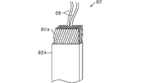
導線82は、導体82aの表面が絶縁被膜82bにより被覆された被覆導線よりなり、径方向に互いに重なる導線82同士の間、及び導線82と固定子コア52との間においてそれぞれ絶縁性が確保されている。導線82における絶縁被膜82bの厚さは例えば80μmであり、これは一般に使用される導線の被膜厚さ(20〜40μm)よりも厚肉となっている。これにより、導線82と固定子コア52との間に絶縁紙等を介在させることをしなくても、これら両者の間の絶縁性が確保されている。なお、導線82により構成される各相巻線は、接続のための露出部分を除き、絶縁被膜82bによる絶縁性が保持されるものとなっている。露出部分としては、例えば、入出力端子部や、星形結線とする場合の中性点部分である。導線群81では、樹脂固着や自己融着被覆線を用いて、径方向に隣り合う各導線82が相互に固着されている。これにより、導線82同士が擦れ合うことによる絶縁破壊や、振動、音が抑制される。 The conductor 82 is composed of a coated conductor whose surface of the conductor 82a is covered with an insulating coating 82b, and insulation is ensured between the conductors 82 that overlap each other in the radial direction and between the conductor 82 and the stator core 52, respectively. ing. The thickness of the insulating coating 82b in the conducting wire 82 is, for example, 80 μm, which is thicker than the film thickness (20 to 40 μm) of the generally used conducting wire. As a result, the insulating property between the conductor 82 and the stator core 52 is ensured without interposing an insulating paper or the like between the conductor 82 and the stator core 52. Each phase winding composed of the conducting wire 82 retains the insulating property by the insulating coating 82b except for the exposed portion for connection. The exposed portion is, for example, an input / output terminal portion or a neutral point portion in the case of a star-shaped connection. In the conductor group 81, the conductors 82 adjacent to each other in the radial direction are fixed to each other by using resin fixing or self-bonding coated wire. As a result, dielectric breakdown, vibration, and sound due to the rubbing of the conducting wires 82 against each other are suppressed.

本実施形態では、導体82aが複数の素線86の集合体として構成されている。具体的には、図13に示すように、導体82aは、複数の素線86を撚ることで撚糸状に形成されている。また、図14に示すように、素線86は、細い繊維状の導電材87を束ねた複合体として構成されている。例えば、素線86はCNT(カーボンナノチューブ)繊維の複合体であり、CNT繊維として、炭素の少なくとも一部をホウ素で置換したホウ素含有微細繊維を含む繊維が用いられている。炭素系微細繊維としては、CNT繊維以外に、気相成長法炭素繊維(VGCF)等を用いることができるが、CNT繊維を用いることが好ましい。なお、素線86の表面は、エナメルやPEEK樹脂やPPS樹脂などの高分子絶縁層で覆われている。 In the present embodiment, the conductor 82a is configured as an aggregate of a plurality of strands 86. Specifically, as shown in FIG. 13, the conductor 82a is formed in a twisted state by twisting a plurality of strands 86. Further, as shown in FIG. 14, the strand 86 is configured as a composite in which thin fibrous conductive materials 87 are bundled. For example, the wire 86 is a composite of CNT (carbon nanotube) fibers, and as the CNT fiber, a fiber containing boron-containing fine fibers in which at least a part of carbon is replaced with boron is used. As the carbon-based fine fibers, gas phase growth method carbon fibers (VGCF) and the like can be used in addition to the CNT fibers, but it is preferable to use the CNT fibers. The surface of the wire 86 is covered with a polymer insulating layer such as enamel, PEEK resin, or PPS resin.

上記の導体82aでは、複数の素線86が撚り合わされて構成されているため、各素線86での渦電流の発生が抑えられ、導体82aにおける渦電流の低減を図ることができる。また、各素線86が捻られていることで、1本の素線86において磁界の印加方向が互いに逆になる部位が生じて逆起電圧が相殺される。そのため、やはり渦電流の低減を図ることができる。特に、素線86を繊維状の導電材87により構成することで、細線化することと捻り回数を格段に増やすこととが可能になり、渦電流をより好適に低減することができる。 Since the conductor 82a is configured by twisting a plurality of strands 86, it is possible to suppress the generation of eddy currents in each of the strands 86 and reduce the eddy currents in the conductor 82a. Further, since each wire 86 is twisted, a portion where the magnetic field application directions are opposite to each other is generated in one wire 86, and the counter electromotive voltage is canceled out. Therefore, the eddy current can also be reduced. In particular, by forming the wire 86 with the fibrous conductive material 87, it is possible to make the wire thinner and to significantly increase the number of twists, and it is possible to more preferably reduce the eddy current.

上述のとおり導線82は、断面が扁平矩形状をなし、径方向に複数並べて配置されるものとなっており、例えば複数の素線86を撚った状態で集合させ、その状態で合成樹脂等により所望の形状に固めて成形するとよい。 As described above, the conductor 82 has a flat rectangular cross section and is arranged side by side in the radial direction. For example, a plurality of strands 86 are assembled in a twisted state, and a synthetic resin or the like is formed in that state. It is preferable to solidify and mold into a desired shape.

各導線82は、周方向に所定の配置パターンで配置されるように折り曲げ形成されており、これにより、固定子巻線51として相ごとの相巻線が形成されている。図12に示すように、固定子巻線51では、各導線82のうち軸方向に直線状に延びる直線部83によりコイルサイド部53が形成され、軸方向においてコイルサイド部53よりも両外側に突出するターン部84によりコイルエンド部54,55が形成されている。各導線82は、直線部83とターン部84とが交互に繰り返されることにより、波巻状の一連の導線として構成されている。直線部83は、磁石部42に対して径方向に対向する位置に配置されており、磁石部42の軸方向外側となる位置において所定間隔を隔てて配置される同相の直線部83同士が、ターン部84により互いに接続されている。なお、直線部83が「磁石対向部」に相当する。 Each conductor 82 is bent and formed so as to be arranged in a predetermined arrangement pattern in the circumferential direction, whereby a phase winding for each phase is formed as a stator winding 51. As shown in FIG. 12, in the stator winding 51, the coil side portion 53 is formed by the straight portion 83 of each conducting wire 82 extending linearly in the axial direction, and the coil side portion 53 is formed on both outer sides of the coil side portion 53 in the axial direction. The coil end portions 54 and 55 are formed by the protruding turn portions 84. Each conductor 82 is configured as a series of wavy conductors by alternately repeating a straight portion 83 and a turn portion 84. The straight line portions 83 are arranged at positions that are radially opposed to the magnet portion 42, and in-phase straight line portions 83 that are arranged at positions that are axially outside the magnet portion 42 and are spaced apart from each other by a predetermined distance. They are connected to each other by a turn portion 84. The straight line portion 83 corresponds to the “magnet facing portion”.

本実施形態では、固定子巻線51が分布巻きにより円環状に巻回形成されている。この場合、コイルサイド部53では、相ごとに、磁石部42の1極対に対応するピッチで周方向に直線部83が配置され、コイルエンド部54,55では、相ごとの各直線部83が、略V字状に形成されたターン部84により互いに接続されている。1極対に対応して対となる各直線部83は、それぞれ電流の向きが互いに逆になるものとなっている。また、一方のコイルエンド部54と他方のコイルエンド部55とでは、ターン部84により接続される一対の直線部83の組み合わせがそれぞれ相違しており、そのコイルエンド部54,55での接続が周方向に繰り返されることにより、固定子巻線51が略円筒状に形成されている。 In the present embodiment, the stator winding 51 is wound in an annular shape by distributed winding. In this case, in the coil side portion 53, the straight portion 83 is arranged in the circumferential direction at a pitch corresponding to one pole pair of the magnet portion 42 for each phase, and in the coil end portions 54 and 55, each straight portion 83 for each phase is arranged. Are connected to each other by a turn portion 84 formed in a substantially V shape. The directions of the currents of the linear portions 83 that are paired corresponding to the one-pole pair are opposite to each other. Further, the combination of the pair of straight line portions 83 connected by the turn portion 84 is different between the one coil end portion 54 and the other coil end portion 55, and the connections at the coil end portions 54 and 55 are different. By repeating in the circumferential direction, the stator winding 51 is formed in a substantially cylindrical shape.

より具体的には、固定子巻線51は、各相2対ずつの導線82を用いて相ごとの巻線を構成しており、固定子巻線51のうち一方の3相巻線(U相、V相、W相)と他方の3相巻線(X相、Y相、Z相)とが径方向内外の2層に設けられるものとなっている。この場合、巻線の相数をS、導線82の対数をmとすれば、極対ごとに2×S×m=2Sm個の導線群81が形成されることになる。本実施形態では、相数Sが3、対数mが2であり、8極対(16極)の回転電機であることから、2×3×2×8=96の導線群81が周方向に配置されている。 More specifically, the stator winding 51 comprises two pairs of lead wires 82 for each phase to form a winding for each phase, and one of the stator windings 51 is a three-phase winding (U). (Phase, V phase, W phase) and the other three-phase winding (X phase, Y phase, Z phase) are provided in two layers inside and outside in the radial direction. In this case, assuming that the number of phases of the winding is S and the logarithm of the conducting wires 82 is m, 2 × S × m = 2Sm of conducting wire groups 81 are formed for each pole pair. In the present embodiment, the number of phases S is 3, the logarithm m is 2, and since it is an 8-pole pair (16-pole) rotary electric machine, the conductor group 81 of 2 × 3 × 2 × 8 = 96 is arranged in the circumferential direction. Have been placed.

図12に示す固定子巻線51では、コイルサイド部53において、径方向内外の2層で直線部83が重ねて配置されるとともに、コイルエンド部54,55において、径方向内外に重なる各直線部83から、互いに周方向逆となる向きでターン部84が周方向に延びる構成となっている。つまり、径方向に隣り合う各導線82では、コイル端となる部分を除き、ターン部84の向きが互いに逆となっている。 In the stator winding 51 shown in FIG. 12, in the coil side portion 53, the straight line portions 83 are arranged in two layers inside and outside in the radial direction, and the straight lines in the coil end portions 54 and 55 overlap each other in the radial direction. The turn portion 84 extends in the circumferential direction from the portion 83 in a direction opposite to each other in the circumferential direction. That is, in each of the conducting wires 82 adjacent to each other in the radial direction, the directions of the turn portions 84 are opposite to each other except for the portion that becomes the coil end.

ここで、固定子巻線51における導線82の巻回構造を具体的に説明する。本実施形態では、波巻にて形成された複数の導線82を、径方向内外に複数層(例えば2層)に重ねて設ける構成としている。図15は、n層目における各導線82の形態を示す図であり、(a)には、固定子巻線51の側方から見た導線82の形状を示し、(b)には、固定子巻線51の軸方向一側から見た導線82の形状を示している。なお、図15では、導線群81が配置される位置をそれぞれD1,D2,D3,…と示している。また、説明の便宜上、3本の導線82のみを示しており、それを第1導線82_A、第2導線82_B、第3導線82_Cとしている。 Here, the winding structure of the conducting wire 82 in the stator winding 51 will be specifically described. In the present embodiment, a plurality of conductors 82 formed by wave winding are provided in a plurality of layers (for example, two layers) in and out of the radial direction. 15A and 15B are views showing the form of each conducting wire 82 in the nth layer, FIG. 15A shows the shape of the conducting wire 82 seen from the side of the stator winding 51, and FIG. 15B shows the shape of the conducting wire 82 fixed. The shape of the conducting wire 82 seen from one side in the axial direction of the child winding 51 is shown. In FIG. 15, the positions where the conductor group 81 is arranged are shown as D1, D2, D3, ..., Respectively. Further, for convenience of explanation, only three conductors 82 are shown, which are referred to as the first conductor 82_A, the second conductor 82_B, and the third conductor 82_C.

各導線82_A〜82_Cでは、直線部83が、いずれもn層目の位置、すなわち径方向において同じ位置に配置され、周方向に6位置(3×m対分)ずつ離れた直線部83同士がターン部84により互いに接続されている。換言すると、各導線82_A〜82_Cでは、いずれも回転子40の軸心を中心とする同一のピッチ円上において、5個おきの直線部83がターン部84により互いに接続されている。例えば第1導線82_Aでは、一対の直線部83がD1,D7にそれぞれ配置され、その一対の直線部83同士が、逆V字状のターン部84により接続されている。また、他の導線82_B,82_Cは、同じn層目において周方向の位置を1つずつずらしてそれぞれ配置されている。この場合、各導線82_A〜82_Cは、いずれも同じ層に配置されるため、ターン部84が互いに干渉することが考えられる。そのため本実施形態では、各導線82_A〜82_Cのターン部84に、その一部を径方向にオフセットした干渉回避部を形成することとしている。 In each of the conducting wires 82_A to 82_C, the straight line portions 83 are all arranged at the nth layer position, that is, at the same position in the radial direction, and the straight line portions 83 separated by 6 positions (3 × m pairs) in the circumferential direction are separated from each other. They are connected to each other by a turn portion 84. In other words, in each of the conducting wires 82_A to 82_C, every five straight lines 83 are connected to each other by the turn 84 on the same pitch circle centered on the axis of the rotor 40. For example, in the first conductor 82_A, a pair of straight lines 83 are arranged at D1 and D7, respectively, and the pair of straight lines 83 are connected to each other by an inverted V-shaped turn portion 84. Further, the other conductors 82_B and 82_C are arranged in the same n-th layer with their circumferential positions shifted by one. In this case, since the conductors 82_A to 82_C are all arranged in the same layer, it is conceivable that the turn portions 84 interfere with each other. Therefore, in the present embodiment, an interference avoidance portion is formed in the turn portion 84 of each of the conducting wires 82_A to 82_C with a part thereof offset in the radial direction.

具体的には、各導線82_A〜82_Cのターン部84は、同一のピッチ円上で周方向に延びる部分である傾斜部84aと、傾斜部84aからその同一のピッチ円よりも径方向内側(図15(b)において上側)にシフトし、別のピッチ円上で周方向に延びる部分である頂部84b、傾斜部84c及び戻り部84dとを有している。頂部84b、傾斜部84c及び戻り部84dが干渉回避部に相当する。なお、傾斜部84cは、傾斜部84aに対して径方向外側にシフトする構成であってもよい。 Specifically, the turn portions 84 of the conducting wires 82_A to 82_C have an inclined portion 84a which is a portion extending in the circumferential direction on the same pitch circle and a radial inside of the same pitch circle from the inclined portion 84a (FIG. It has a top portion 84b, an inclined portion 84c, and a return portion 84d, which are portions extending in the circumferential direction on another pitch circle that are shifted to the upper side at 15 (b). The top portion 84b, the inclined portion 84c, and the return portion 84d correspond to the interference avoidance portion. The inclined portion 84c may be configured to shift outward in the radial direction with respect to the inclined portion 84a.

つまり、各導線82_A〜82_Cのターン部84は、周方向の中央位置である頂部84bを挟んでその両側に、一方側の傾斜部84aと他方側の傾斜部84cとを有しており、それら各傾斜部84a,84cの径方向の位置(図15(a)では紙面前後方向の位置、図15(b)では上下方向の位置)が互いに相違するものとなっている。例えば第1導線82_Aのターン部84は、n層のD1位置を始点位置として周方向に沿って延び、周方向の中央位置である頂部84bで径方向(例えば径方向内側)に曲がった後、周方向に再度曲がることで、再び周方向に沿って延び、さらに戻り部84dで再び径方向(例えば径方向外側)に曲がることで、終点位置であるn層のD9位置に達する構成となっている。 That is, the turn portions 84 of the conducting wires 82_A to 82_C have an inclined portion 84a on one side and an inclined portion 84c on the other side on both sides of the top portion 84b which is a central position in the circumferential direction. The radial positions of the inclined portions 84a and 84c (the position in the front-rear direction of the paper surface in FIG. 15A and the position in the vertical direction in FIG. 15B) are different from each other. For example, the turn portion 84 of the first lead wire 82_A extends along the circumferential direction starting from the D1 position of the n-layer, bends in the radial direction (for example, inward in the radial direction) at the top portion 84b, which is the central position in the circumferential direction, and then. By bending again in the circumferential direction, it extends along the circumferential direction again, and further bends in the radial direction (for example, outside in the radial direction) again at the return portion 84d to reach the D9 position of the n layer, which is the end point position. There is.

上記構成によれば、導線82_A〜82_Cでは、一方の各傾斜部84aが、上から第1導線82_A→第2導線82_B→第3導線82_Cの順に上下に並ぶとともに、頂部84bで各導線82_A〜82_Cの上下が入れ替わり、他方の各傾斜部84cが、上から第3導線82_C→第2導線82_B→第1導線82_Aの順に上下に並ぶ構成となっている。そのため、各導線82_A〜82_Cが互いに干渉することなく周方向に配置できるようになっている。 According to the above configuration, in the conductors 82_A to 82_C, one of the inclined portions 84a is arranged vertically in the order of the first conductor 82_A → the second conductor 82_B → the third conductor 82_C from the top, and each conductor 82_A to the top 84b. The top and bottom of 82_C are interchanged, and the other inclined portions 84c are arranged vertically in the order of the third conductor 82_C → the second conductor 82_B → the first conductor 82_A from the top. Therefore, the conductors 82_A to 82_C can be arranged in the circumferential direction without interfering with each other.

ここで、複数の導線82を径方向に重ねて導線群81とする構成において、複数層の各直線部83のうち径方向内側の直線部83に接続されたターン部84と、径方向外側の直線部83に接続されたターン部84とが、それら各直線部83同士よりも径方向に離して配置されているとよい。また、ターン部84の端部、すなわち直線部83との境界部付近で、複数層の導線82が径方向の同じ側に曲げられる場合に、その隣り合う層の導線82同士の干渉により絶縁性が損なわれることが生じないようにするとよい。 Here, in a configuration in which a plurality of lead wires 82 are stacked in the radial direction to form a lead wire group 81, a turn portion 84 connected to the linear portion 83 on the inner side in the radial direction and a turn portion 84 connected to the straight portion 83 on the inner side in the radial direction among the straight line portions 83 of the plurality of layers and the outer side in the radial direction. It is preferable that the turn portion 84 connected to the straight portion 83 is arranged so as to be radially separated from each of the straight portions 83. Further, when the conductors 82 of a plurality of layers are bent to the same side in the radial direction near the end of the turn portion 84, that is, the boundary portion with the straight portion 83, the conductors 82 of the adjacent layers have an insulating property due to interference between the conductors 82. It is good to prevent the damage from being damaged.

例えば図15のD7〜D9では、径方向に重なる各導線82が、ターン部84の戻り部84dでそれぞれ径方向に曲げられる。この場合、図16に示すように、n層目の導線82とn+1層目の導線82とで、曲がり部の曲げアールを相違させるとよい。具体的には、径方向内側(n層目)の導線82の曲げアールR1を、径方向外側(n+1層目)の導線82の曲げアールR2よりも小さくする。 For example, in D7 to D9 of FIG. 15, each of the conducting wires 82 overlapping in the radial direction is bent in the radial direction at the return portion 84d of the turn portion 84. In this case, as shown in FIG. 16, it is preferable that the bending radius of the bent portion is different between the conductor 82 of the nth layer and the conductor 82 of the n + 1 layer. Specifically, the bending radius R1 of the conductor 82 on the inner side (nth layer) in the radial direction is made smaller than the bending radius R2 of the conductor 82 on the outer side (n + 1th layer) in the radial direction.

また、n層目の導線82とn+1層目の導線82とで、径方向のシフト量を相違させるとよい。具体的には、径方向内側(n層目)の導線82のシフト量S1を、径方向外側(n+1層目)の導線82のシフト量S2よりも大きくする。 Further, it is preferable that the radial shift amount is different between the nth layer conductor 82 and the n + 1th layer conductor 82. Specifically, the shift amount S1 of the conductor 82 on the inner side (nth layer) in the radial direction is made larger than the shift amount S2 of the conductor 82 on the outer side (n + 1 layer) in the radial direction.

上記構成により、径方向に重なる各導線82が同じ向きに曲げられる場合であっても、各導線82の相互干渉を好適に回避することができる。これにより、良好な絶縁性が得られることとなる。 With the above configuration, mutual interference of the conductors 82 can be suitably avoided even when the conductors 82 overlapping in the radial direction are bent in the same direction. As a result, good insulation can be obtained.

次に、回転子40における磁石部42の構造について説明する。本実施形態では、永久磁石として、残留磁束密度Br=1.0[T]、保磁力bHc=400[kA/m]以上のものを想定している。5000〜10000[AT]が相間励磁により掛かるものであるから、1極対で25[mm]の永久磁石を使えば、bHc=10000[A]となり、減磁をしないことが伺える。ここで、本実施形態においては、配向により磁化容易軸をコントロールした永久磁石を利用しているから、その磁石内部の磁気回路長を、従来1.0[T]以上を出す直線配向磁石の磁気回路長と比べて、長くすることができる。すなわち、1極対あたりの磁気回路長を、少ない磁石量で達成できる他、従来の直線配向磁石を利用した設計と比べ、過酷な高熱条件に曝されても、その可逆減磁範囲を保つことができる。また、本願発明者は、従来技術の磁石を用いても、極異方性磁石と近しい特性を得られる構成を見いだした。 Next, the structure of the magnet portion 42 in the rotor 40 will be described. In this embodiment, it is assumed that the permanent magnet has a residual magnetic flux density Br = 1.0 [T] and a coercive force bHc = 400 [kA / m] or more. Since 5000 to 10000 [AT] is applied by interphase excitation, if a permanent magnet of 25 [mm] is used for one pole pair, bHc = 10000 [A], and it can be seen that demagnetization is not performed. Here, in the present embodiment, since a permanent magnet whose magnetization easy axis is controlled by orientation is used, the magnetism of the linearly oriented magnet that conventionally produces a magnetic circuit length of 1.0 [T] or more inside the magnet. It can be made longer than the circuit length. That is, the magnetic circuit length per pole pair can be achieved with a small amount of magnets, and the reversible demagnetization range is maintained even when exposed to harsh high thermal conditions, as compared with the conventional design using linearly oriented magnets. Can be done. Further, the inventor of the present application has found a configuration in which characteristics similar to those of a polar anisotropic magnet can be obtained even by using a magnet of the prior art.

図8及び図9に示すように、磁石部42は、円環状をなしており、回転子本体41の内側(詳しくは磁石保持部43の径方向内側)に設けられている。磁石部42は、それぞれ極異方性磁石でありかつ磁極が互いに異なる第1磁石91及び第2磁石92を有している。第1磁石91及び第2磁石92は周方向に交互に配置されている。第1磁石91は、回転子40においてN極となる磁石であり、第2磁石92は、回転子40においてS極となる磁石である。第1磁石91及び第2磁石92は、例えばネオジム磁石等の希土類磁石からなる永久磁石である。 As shown in FIGS. 8 and 9, the magnet portion 42 has an annular shape and is provided inside the rotor main body 41 (specifically, inside the magnet holding portion 43 in the radial direction). The magnet portion 42 has a first magnet 91 and a second magnet 92, which are polar anisotropic magnets and have different magnetic poles. The first magnet 91 and the second magnet 92 are arranged alternately in the circumferential direction. The first magnet 91 is a magnet having an N pole in the rotor 40, and the second magnet 92 is a magnet having an S pole in the rotor 40. The first magnet 91 and the second magnet 92 are permanent magnets made of rare earth magnets such as neodymium magnets.

各磁石91,92では、それぞれ磁極中心であるd軸と磁極境界であるq軸との間において磁化方向が円弧状に延びている。各磁石91,92それぞれにおいて、d軸側では磁化方向が径方向とされ、q軸側では磁化方向が周方向とされている。磁石部42では、各磁石91,92により、隣接するN,S極間を円弧状に磁束が流れるため、例えばラジアル異方性磁石に比べて磁石磁路が長くなっている。このため、図17に示すように、磁束密度分布が正弦波に近いものとなる。その結果、図18に比較例として示すラジアル異方性磁石の磁束密度分布とは異なり、磁極位置に磁束を集中させることができ、回転電機10のトルクを高めることができる。なお、図17及び図18において、横軸は電気角を示し、縦軸は磁束密度を示す。また、図17及び図18において、横軸の90°はd軸(すなわち磁極中心)を示し、横軸の0°,180°はq軸を示す。 In each of the magnets 91 and 92, the magnetization direction extends in an arc shape between the d-axis which is the center of the magnetic pole and the q-axis which is the boundary of the magnetic poles. In each of the magnets 91 and 92, the magnetization direction is the radial direction on the d-axis side, and the magnetization direction is the circumferential direction on the q-axis side. In the magnet portion 42, magnetic flux flows in an arc shape between adjacent N and S poles due to the magnets 91 and 92, so that the magnet path is longer than that of, for example, a radial anisotropic magnet. Therefore, as shown in FIG. 17, the magnetic flux density distribution is close to that of a sine wave. As a result, unlike the magnetic flux density distribution of the radial anisotropic magnet shown as a comparative example in FIG. 18, the magnetic flux can be concentrated at the magnetic pole position, and the torque of the rotary electric machine 10 can be increased. In FIGS. 17 and 18, the horizontal axis represents the electric angle and the vertical axis represents the magnetic flux density. Further, in FIGS. 17 and 18, 90 ° on the horizontal axis indicates the d-axis (that is, the center of the magnetic pole), and 0 ° and 180 ° on the horizontal axis indicate the q-axis.

また、磁束密度分布の正弦波整合率は、例えば40%以上の値とされていればよい。このようにすれば、正弦波整合率が30%程度であるラジアル配向磁石、パラレル配向磁石を用いる場合に比べ、確実に波形中央部分の磁束量を向上させることができる。また、正弦波整合率を60%以上とすれば、ハルバッハ配列と呼ばれる磁束集中配列と比べ、確実に波形中央部分の磁束量を向上させることができる。 Further, the sine wave matching factor of the magnetic flux density distribution may be, for example, a value of 40% or more. By doing so, it is possible to surely improve the amount of magnetic flux in the central portion of the waveform as compared with the case of using a radial alignment magnet or a parallel alignment magnet having a sinusoidal matching ratio of about 30%. Further, if the sine wave matching factor is 60% or more, the amount of magnetic flux in the central portion of the waveform can be surely improved as compared with the magnetic flux concentrated array called the Halbach array.

図18に示す比較例では、q軸付近において磁束密度が急峻に変化する。磁束密度の変化が急峻なほど、固定子巻線51に発生する渦電流が増加してしまう。これに対し、本実施形態では、磁束密度分布が正弦波に近い。このため、q軸付近において、磁束密度の変化が、ラジアル異方性磁石の磁束密度の変化よりも小さい。これにより、渦電流の発生を抑制することができる。 In the comparative example shown in FIG. 18, the magnetic flux density changes sharply near the q-axis. The steeper the change in magnetic flux density, the greater the eddy current generated in the stator winding 51. On the other hand, in the present embodiment, the magnetic flux density distribution is close to a sinusoidal wave. Therefore, the change in the magnetic flux density near the q-axis is smaller than the change in the magnetic flux density of the radial anisotropic magnet. As a result, the generation of eddy current can be suppressed.

ところで、磁石部42では、各磁石91,92のd軸付近(すなわち磁極中心)において磁極面に直交する向きで磁束が生じ、その磁束は、磁極面から離れるほど、d軸から離れるような円弧状をなす。また、磁極面に直交する磁束ほど、強い磁束となる。この点において、本実施形態の回転電機10では、上述のとおり各導線群81を径方向に薄くしたため、導線群81の径方向の中心位置が磁石部42の磁極面に近づくことになり、固定子50において回転子40から強い磁石磁束を受けることができる。 By the way, in the magnet portion 42, a magnetic flux is generated in the vicinity of the d-axis (that is, the center of the magnetic pole) of each of the magnets 91 and 92 in a direction orthogonal to the magnetic pole surface, and the magnetic flux is a circle that moves away from the d-axis as the distance from the magnetic pole surface increases. It forms an arc. Further, the magnetic flux orthogonal to the magnetic pole surface becomes stronger. In this respect, in the rotary electric machine 10 of the present embodiment, since each lead wire group 81 is thinned in the radial direction as described above, the radial center position of the lead wire group 81 approaches the magnetic flux surface of the magnet portion 42 and is fixed. The child 50 can receive a strong magnetic flux from the rotor 40.

また、固定子50には、固定子巻線51の径方向内側、すなわち固定子巻線51を挟んで回転子40の逆側に円筒状の固定子コア52が設けられている。そのため、各磁石91,92の磁極面から延びる磁束は、固定子コア52に引きつけられ、固定子コア52を磁路の一部として用いつつ周回する。この場合、磁石磁束の向き及び経路を適正化することができる。 Further, the stator 50 is provided with a cylindrical stator core 52 on the radial inside of the stator winding 51, that is, on the opposite side of the rotor 40 with the stator winding 51 interposed therebetween. Therefore, the magnetic flux extending from the magnetic pole surfaces of the magnets 91 and 92 is attracted to the stator core 52 and orbits while using the stator core 52 as a part of the magnetic path. In this case, the direction and path of the magnetic flux of the magnet can be optimized.

次に、回転電機10を制御する制御システムの構成について説明する。図19は、回転電機10の制御システムの電気回路図であり、図20は、制御装置110による制御処理を示す機能ブロック図である。 Next, the configuration of the control system that controls the rotary electric machine 10 will be described. FIG. 19 is an electric circuit diagram of the control system of the rotary electric machine 10, and FIG. 20 is a functional block diagram showing a control process by the control device 110.

図19では、固定子巻線51として2組の3相巻線51a,51bが示されており、3相巻線51aはU相巻線、V相巻線及びW相巻線よりなり、3相巻線51bはX相巻線、Y相巻線及びZ相巻線よりなる。3相巻線51a,51bごとに、第1インバータ101と第2インバータ102とがそれぞれ設けられている。インバータ101,102は、相巻線の相数と同数の上下アームを有するフルブリッジ回路により構成されており、各アームに設けられたスイッチ(半導体スイッチング素子)のオンオフにより、固定子巻線51の各相巻線において通電電流が調整される。 In FIG. 19, two sets of three-phase windings 51a and 51b are shown as the stator windings 51, and the three-phase winding 51a is composed of a U-phase winding, a V-phase winding, and a W-phase winding. The phase winding 51b includes an X-phase winding, a Y-phase winding, and a Z-phase winding. A first inverter 101 and a second inverter 102 are provided for each of the three-phase windings 51a and 51b, respectively. The inverters 101 and 102 are composed of a full bridge circuit having the same number of upper and lower arms as the number of phases of the phase windings, and the stator windings 51 can be turned on and off by turning on / off a switch (semiconductor switching element) provided on each arm. The energizing current is adjusted in each phase winding.

各インバータ101,102には、直流電源103と平滑用のコンデンサ104とが並列に接続されている。直流電源103は、例えば複数の単電池が直列接続された組電池により構成されている。なお、インバータ101,102の各スイッチが、図1等に示す半導体モジュール66に相当し、コンデンサ104が、図1等に示すコンデンサモジュール68に相当する。 A DC power supply 103 and a smoothing capacitor 104 are connected in parallel to each of the inverters 101 and 102. The DC power supply 103 is composed of, for example, an assembled battery in which a plurality of single batteries are connected in series. The switches of the inverters 101 and 102 correspond to the semiconductor module 66 shown in FIG. 1 and the like, and the capacitor 104 corresponds to the capacitor module 68 shown in FIG. 1 and the like.

制御装置110は、CPUや各種メモリからなるマイコンを備えており、回転電機10における各種の検出情報や、力行駆動及び発電の要求に基づいて、インバータ101,102における各スイッチのオンオフにより通電制御を実施する。制御装置110が、図6に示す制御装置77に相当する。回転電機10の検出情報には、例えば、レゾルバ等の角度検出器により検出される回転子40の回転角度(電気角情報)や、電圧センサにより検出される電源電圧(インバータ入力電圧)、電流センサにより検出される各相の通電電流が含まれる。制御装置110は、インバータ101,102の各スイッチを操作する操作信号を生成して出力する。なお、発電の要求は、例えば回転電機10が車両用動力源として用いられる場合、回生駆動の要求である。 The control device 110 includes a microcomputer composed of a CPU and various memories, and performs energization control by turning on / off each switch in the inverters 101 and 102 based on various detection information in the rotary electric machine 10 and a request for power running drive and power generation. implement. The control device 110 corresponds to the control device 77 shown in FIG. The detection information of the rotary electric machine 10 includes, for example, the rotation angle (electric angle information) of the rotor 40 detected by an angle detector such as a resolver, the power supply voltage (inverter input voltage) detected by the voltage sensor, and the current sensor. Includes the energizing current of each phase detected by. The control device 110 generates and outputs an operation signal for operating each of the switches of the inverters 101 and 102. The power generation requirement is, for example, a regenerative drive requirement when the rotary electric machine 10 is used as a power source for a vehicle.

第1インバータ101は、U相、V相及びW相からなる3相において上アームスイッチSpと下アームスイッチSnとの直列接続体をそれぞれ備えている。各相の上アームスイッチSpの高電位側端子は直流電源103の正極端子に接続され、各相の下アームスイッチSnの低電位側端子は直流電源103の負極端子(グランド)に接続されている。各相の上アームスイッチSpと下アームスイッチSnとの間の中間接続点には、それぞれU相巻線、V相巻線、W相巻線の一端が接続されている。これら各相巻線は星形結線(Y結線)されており、各相巻線の他端は中性点にて互いに接続されている。 The first inverter 101 includes a series connection body of the upper arm switch Sp and the lower arm switch Sn in three phases including the U phase, the V phase, and the W phase. The high potential side terminal of the upper arm switch Sp of each phase is connected to the positive electrode terminal of the DC power supply 103, and the low potential side terminal of the lower arm switch Sn of each phase is connected to the negative electrode terminal (ground) of the DC power supply 103. .. One ends of the U-phase winding, the V-phase winding, and the W-phase winding are connected to the intermediate connection points between the upper arm switch Sp and the lower arm switch Sn of each phase, respectively. Each of these phase windings is star-shaped (Y-connected), and the other end of each phase winding is connected to each other at a neutral point.

第2インバータ102は、第1インバータ101と同様の構成を有しており、X相、Y相及びZ相からなる3相において上アームスイッチSpと下アームスイッチSnとの直列接続体をそれぞれ備えている。各相の上アームスイッチSpの高電位側端子は直流電源103の正極端子に接続され、各相の下アームスイッチSnの低電位側端子は直流電源103の負極端子(グランド)に接続されている。各相の上アームスイッチSpと下アームスイッチSnとの間の中間接続点には、それぞれX相巻線、Y相巻線、Z相巻線の一端が接続されている。これら各相巻線は星形結線(Y結線)されており、各相巻線の他端は中性点で互いに接続されている。 The second inverter 102 has the same configuration as the first inverter 101, and includes a series connection body of the upper arm switch Sp and the lower arm switch Sn in three phases including the X phase, the Y phase, and the Z phase. ing. The high potential side terminal of the upper arm switch Sp of each phase is connected to the positive electrode terminal of the DC power supply 103, and the low potential side terminal of the lower arm switch Sn of each phase is connected to the negative electrode terminal (ground) of the DC power supply 103. .. One ends of the X-phase winding, the Y-phase winding, and the Z-phase winding are connected to the intermediate connection points between the upper arm switch Sp and the lower arm switch Sn of each phase, respectively. Each of these phase windings is star-shaped (Y-connected), and the other end of each phase winding is connected to each other at a neutral point.

図20には、U,V,W相の各相電流を制御する電流フィードバック制御処理と、X,Y,Z相の各相電流を制御する電流フィードバック制御処理とが示されている。ここではまず、U,V,W相側の制御処理について説明する。 FIG. 20 shows a current feedback control process for controlling each phase current of the U, V, and W phases, and a current feedback control process for controlling each phase current of the X, Y, and Z phases. Here, first, the control processing on the U, V, and W phases will be described.

図20において、電流指令値設定部111は、トルク−dqマップを用い、回転電機10に対する力行トルク指令値又は発電トルク指令値や、電気角θを時間微分して得られる電気角速度ωに基づいて、d軸の電流指令値とq軸の電流指令値とを設定する。なお、電流指令値設定部111は、U,V,W相側及びX,Y,Z相側において共通に設けられている。なお、発電トルク指令値は、例えば回転電機10が車両用動力源として用いられる場合、回生トルク指令値である。 In FIG. 20, the current command value setting unit 111 uses the torque −dq map and is based on the power running torque command value or the power generation torque command value for the rotary electric machine 10 and the electric angular velocity ω obtained by time-differentiating the electric angle θ. , The d-axis current command value and the q-axis current command value are set. The current command value setting unit 111 is commonly provided on the U, V, W phase side and the X, Y, Z phase side. The power generation torque command value is, for example, a regenerative torque command value when the rotary electric machine 10 is used as a power source for a vehicle.

dq変換部112は、相ごとに設けられた電流センサによる電流検出値(各相電流)を、界磁方向をd軸とする直交2次元回転座標系の成分であるd軸電流とq軸電流とに変換する。 The dq conversion unit 112 uses the current detection value (each phase current) of the current sensor provided for each phase as the d-axis current and the q-axis current, which are components of the orthogonal two-dimensional rotating coordinate system with the field direction as the d-axis. Convert to and.

d軸電流フィードバック制御部113は、d軸電流をd軸の電流指令値にフィードバック制御するための操作量としてd軸の指令電圧を算出する。また、q軸電流フィードバック制御部114は、q軸電流をq軸の電流指令値にフィードバック制御するための操作量としてq軸の指令電圧を算出する。これら各フィードバック制御部113,114では、d軸電流及びq軸電流の電流指令値に対する偏差に基づき、PIフィードバック手法を用いて指令電圧が算出される。 The d-axis current feedback control unit 113 calculates the d-axis command voltage as an operation amount for feedback-controlling the d-axis current to the d-axis current command value. Further, the q-axis current feedback control unit 114 calculates the q-axis command voltage as an operation amount for feedback-controlling the q-axis current to the q-axis current command value. In each of these feedback control units 113 and 114, the command voltage is calculated using the PI feedback method based on the deviation of the d-axis current and the q-axis current with respect to the current command value.

3相変換部115は、d軸及びq軸の指令電圧を、U相、V相及びW相の指令電圧に変換する。なお、上記の各部111〜115が、dq変換理論による基本波電流のフィードバック制御を実施するフィードバック制御部であり、U相、V相及びW相の指令電圧がフィードバック制御値である。 The three-phase conversion unit 115 converts the d-axis and q-axis command voltages into U-phase, V-phase, and W-phase command voltages. Each of the above units 111 to 115 is a feedback control unit that performs feedback control of the fundamental wave current according to the dq conversion theory, and the U-phase, V-phase, and W-phase command voltages are feedback control values.

そして、操作信号生成部116は、周知の三角波キャリア比較方式を用い、3相の指令電圧に基づいて、第1インバータ101の操作信号を生成する。具体的には、操作信号生成部116は、3相の指令電圧を電源電圧で規格化した信号と、三角波信号等のキャリア信号との大小比較に基づくPWM制御により、各相における上下アームのスイッチ操作信号(デューティ信号)を生成する。 Then, the operation signal generation unit 116 uses a well-known triangular wave carrier comparison method to generate an operation signal of the first inverter 101 based on the three-phase command voltage. Specifically, the operation signal generation unit 116 switches the upper and lower arms in each phase by PWM control based on the magnitude comparison between the signal obtained by standardizing the command voltage of the three phases with the power supply voltage and the carrier signal such as the triangular wave signal. Generates an operation signal (duty signal).

また、X,Y,Z相側においても同様の構成を有しており、dq変換部122は、相ごとに設けられた電流センサによる電流検出値(各相電流)を、界磁方向をd軸とする直交2次元回転座標系の成分であるd軸電流とq軸電流とに変換する。 Further, the X, Y, and Z phases have the same configuration, and the dq conversion unit 122 sets the current detection value (each phase current) by the current sensor provided for each phase in the field direction. It is converted into a d-axis current and a q-axis current, which are components of an orthogonal two-dimensional rotating coordinate system as an axis.

d軸電流フィードバック制御部123はd軸の指令電圧を算出し、q軸電流フィードバック制御部124はq軸の指令電圧を算出する。3相変換部125は、d軸及びq軸の指令電圧を、X相、Y相及びZ相の指令電圧に変換する。そして、操作信号生成部126は、3相の指令電圧に基づいて、第2インバータ102の操作信号を生成する。具体的には、操作信号生成部126は、3相の指令電圧を電源電圧で規格化した信号と、三角波信号等のキャリア信号との大小比較に基づくPWM制御により、各相における上下アームのスイッチ操作信号(デューティ信号)を生成する。 The d-axis current feedback control unit 123 calculates the d-axis command voltage, and the q-axis current feedback control unit 124 calculates the q-axis command voltage. The three-phase conversion unit 125 converts the d-axis and q-axis command voltages into X-phase, Y-phase, and Z-phase command voltages. Then, the operation signal generation unit 126 generates an operation signal of the second inverter 102 based on the three-phase command voltage. Specifically, the operation signal generation unit 126 switches the upper and lower arms in each phase by PWM control based on the magnitude comparison between the signal obtained by standardizing the command voltage of the three phases with the power supply voltage and the carrier signal such as the triangular wave signal. Generates an operation signal (duty signal).

ドライバ117は、操作信号生成部116,126にて生成されたスイッチ操作信号に基づいて、各インバータ101,102における各3相のスイッチSp,Snをオンオフさせる。 The driver 117 turns on / off the switches Sp and Sn of each of the three phases in the inverters 101 and 102 based on the switch operation signals generated by the operation signal generation units 116 and 126.

続いて、トルクフィードバック制御処理について説明する。この処理は、例えば高回転領域及び高出力領域等、各インバータ101,102の出力電圧が大きくなる運転条件において、主に回転電機10の高出力化や損失低減の目的で用いられる。制御装置110は、回転電機10の運転条件に基づいて、トルクフィードバック制御処理及び電流フィードバック制御処理のいずれか一方の処理を選択して実行する。 Subsequently, the torque feedback control process will be described. This process is mainly used for the purpose of increasing the output of the rotary electric machine 10 and reducing the loss under operating conditions in which the output voltage of each of the inverters 101 and 102 becomes large, such as in a high rotation region and a high output region. The control device 110 selects and executes either the torque feedback control process or the current feedback control process based on the operating conditions of the rotary electric machine 10.

図21には、U,V,W相に対応するトルクフィードバック制御処理と、X,Y,Z相に対応するトルクフィードバック制御処理とが示されている。なお、図21において、図20と同じ構成については、同じ符号を付して説明を省略する。ここではまず、U,V,W相側の制御処理について説明する。 FIG. 21 shows a torque feedback control process corresponding to the U, V, and W phases and a torque feedback control process corresponding to the X, Y, and Z phases. In FIG. 21, the same configurations as those in FIG. 20 are designated by the same reference numerals and the description thereof will be omitted. Here, first, the control processing on the U, V, and W phases will be described.

電圧振幅算出部127は、回転電機10に対する力行トルク指令値又は発電トルク指令値と、電気角θを時間微分して得られる電気角速度ωとに基づいて、電圧ベクトルの大きさの指令値である電圧振幅指令を算出する。 The voltage amplitude calculation unit 127 is a command value of the magnitude of the voltage vector based on the power running torque command value or the power generation torque command value for the rotary electric machine 10 and the electric angular velocity ω obtained by time-differentiating the electric angle θ. Calculate the voltage amplitude command.

トルク推定部128aは、dq変換部112により変換されたd軸電流とq軸電流とに基づいて、U,V,W相に対応するトルク推定値を算出する。なお、トルク推定部128aは、d軸電流、q軸電流及び電圧振幅指令が関係付けられたマップ情報に基づいて、電圧振幅指令を算出すればよい。 The torque estimation unit 128a calculates the torque estimation value corresponding to the U, V, and W phases based on the d-axis current and the q-axis current converted by the dq conversion unit 112. The torque estimation unit 128a may calculate the voltage amplitude command based on the map information associated with the d-axis current, the q-axis current, and the voltage amplitude command.

トルクフィードバック制御部129aは、力行トルク指令値又は発電トルク指令値にトルク推定値をフィードバック制御するための操作量として、電圧ベクトルの位相の指令値である電圧位相指令を算出する。トルクフィードバック制御部129aでは、力行トルク指令値又は発電トルク指令値に対するトルク推定値の偏差に基づき、PIフィードバック手法を用いて電圧位相指令が算出される。 The torque feedback control unit 129a calculates a voltage phase command, which is a command value of the phase of the voltage vector, as an operation amount for feedback-controlling the torque estimation value to the power running torque command value or the generated torque command value. The torque feedback control unit 129a calculates the voltage phase command using the PI feedback method based on the deviation of the torque estimated value with respect to the force running torque command value or the generated torque command value.

操作信号生成部130aは、電圧振幅指令、電圧位相指令及び電気角θに基づいて、第1インバータ101の操作信号を生成する。具体的には、操作信号生成部130aは、電圧振幅指令、電圧位相指令及び電気角θに基づいて3相の指令電圧を算出し、算出した3相の指令電圧を電源電圧で規格化した信号と、三角波信号等のキャリア信号との大小比較に基づくPWM制御により、各相における上下アームのスイッチ操作信号を生成する。 The operation signal generation unit 130a generates an operation signal of the first inverter 101 based on the voltage amplitude command, the voltage phase command, and the electric angle θ. Specifically, the operation signal generation unit 130a calculates a three-phase command voltage based on the voltage amplitude command, the voltage phase command, and the electric angle θ, and the calculated three-phase command voltage is standardized by the power supply voltage. And, by PWM control based on the magnitude comparison with the carrier signal such as the triangular wave signal, the switch operation signal of the upper and lower arms in each phase is generated.

ちなみに、操作信号生成部130aは、電圧振幅指令、電圧位相指令、電気角θ及びスイッチ操作信号が関係付けられたマップ情報であるパルスパターン情報、電圧振幅指令、電圧位相指令並びに電気角θに基づいて、スイッチ操作信号を生成してもよい。 Incidentally, the operation signal generation unit 130a is based on the pulse pattern information, the voltage amplitude command, the voltage phase command, and the electric angle θ, which are map information related to the voltage amplitude command, the voltage phase command, the electric angle θ, and the switch operation signal. The switch operation signal may be generated.

また、X,Y,Z相側においても同様の構成を有しており、トルク推定部128bは、dq変換部122により変換されたd軸電流とq軸電流とに基づいて、X,Y,Z相に対応するトルク推定値を算出する。 Further, the X, Y, Z phase side also has the same configuration, and the torque estimation unit 128b has the X, Y, X, Y, based on the d-axis current and the q-axis current converted by the dq conversion unit 122. The torque estimate corresponding to the Z phase is calculated.

トルクフィードバック制御部129bは、力行トルク指令値又は発電トルク指令値にトルク推定値をフィードバック制御するための操作量として、電圧位相指令を算出する。トルクフィードバック制御部129bでは、力行トルク指令値又は発電トルク指令値に対するトルク推定値の偏差に基づき、PIフィードバック手法を用いて電圧位相指令が算出される。 The torque feedback control unit 129b calculates a voltage phase command as an operation amount for feedback-controlling the torque estimation value to the power running torque command value or the generated torque command value. The torque feedback control unit 129b calculates the voltage phase command using the PI feedback method based on the deviation of the torque estimated value with respect to the power running torque command value or the generated torque command value.

操作信号生成部130bは、電圧振幅指令、電圧位相指令及び電気角θに基づいて、第2インバータ102の操作信号を生成する。具体的には、操作信号生成部130bは、電圧振幅指令、電圧位相指令及び電気角θに基づいて3相の指令電圧を算出し、算出した3相の指令電圧を電源電圧で規格化した信号と、三角波信号等のキャリア信号との大小比較に基づくPWM制御により、各相における上下アームのスイッチ操作信号を生成する。ドライバ117は、操作信号生成部130a,130bにて生成されたスイッチ操作信号に基づいて、各インバータ101,102における各3相のスイッチSp,Snをオンオフさせる。 The operation signal generation unit 130b generates an operation signal of the second inverter 102 based on the voltage amplitude command, the voltage phase command, and the electric angle θ. Specifically, the operation signal generation unit 130b calculates a three-phase command voltage based on the voltage amplitude command, the voltage phase command, and the electric angle θ, and the calculated three-phase command voltage is standardized by the power supply voltage. And, by PWM control based on the magnitude comparison with the carrier signal such as the triangular wave signal, the switch operation signal of the upper and lower arms in each phase is generated. The driver 117 turns on / off the switches Sp and Sn of each of the three phases in the inverters 101 and 102 based on the switch operation signals generated by the operation signal generation units 130a and 130b.

ちなみに、操作信号生成部130bは、電圧振幅指令、電圧位相指令、電気角θ及びスイッチ操作信号が関係付けられたマップ情報であるパルスパターン情報、電圧振幅指令、電圧位相指令並びに電気角θに基づいて、スイッチ操作信号を生成してもよい。 Incidentally, the operation signal generation unit 130b is based on the pulse pattern information, the voltage amplitude command, the voltage phase command, and the electric angle θ, which are map information related to the voltage amplitude command, the voltage phase command, the electric angle θ, and the switch operation signal. The switch operation signal may be generated.

以上詳述した本実施形態によれば、以下の優れた効果が得られる。 According to the present embodiment described in detail above, the following excellent effects can be obtained.

固定子50において、固定子巻線51の周方向に隣り合う直線部83の間(つまり、隣り合う磁石対向部の間)に、軟磁性材からなるティースが設けられていない構成とした。上記構成によれば、各直線部83の間にティースが設けられている場合に比べて、隣り合う各直線部83を近づけることで導体断面積を大きくすることができ、固定子巻線51の通電に伴い生じる発熱を低減することができる。各直線部83の間にティースが設けられていない、いわゆるスロットレス構造では、直線部83間のティースがないことで磁気飽和の解消が可能となり、固定子巻線51への通電電流を増大させることが可能となる。この場合において、その通電電流の増大に伴い発熱量が増えることに好適に対処することができる。以上により、固定子50での放熱性能を適正化することが可能になっている。 In the stator 50, a tooth made of a soft magnetic material is not provided between the straight portions 83 adjacent to each other in the circumferential direction of the stator winding 51 (that is, between the adjacent magnet facing portions). According to the above configuration, the conductor cross-sectional area can be increased by bringing the adjacent straight portions 83 closer to each other as compared with the case where the teeth are provided between the straight portions 83, and the stator winding 51 It is possible to reduce the heat generated by energization. In the so-called slotless structure in which the teeth are not provided between the straight portions 83, the magnetic saturation can be eliminated by the absence of the teeth between the straight portions 83, and the energizing current to the stator winding 51 is increased. It becomes possible. In this case, it is possible to preferably cope with the increase in the amount of heat generated as the energizing current increases. As described above, it is possible to optimize the heat dissipation performance of the stator 50.

固定子巻線51に固定子コア52を組み付け、その組み付け状態において、周方向に隣り合う直線部83の間に、軟磁性材からなるティースが設けられていない構成とした。この場合、回転子40に対して径方向反対側に設けられた固定子コア52がバックヨークとして機能することで、各直線部83の間にティースが存在していなくても、適正な磁気回路の形成が可能となる。 The stator core 52 is assembled to the stator winding 51, and in the assembled state, a tooth made of a soft magnetic material is not provided between the straight portions 83 adjacent to each other in the circumferential direction. In this case, the stator core 52 provided on the side opposite to the rotor 40 in the radial direction functions as a back yoke, so that an appropriate magnetic circuit is provided even if there is no tooth between the straight portions 83. Can be formed.

固定子巻線51を封止材により封止し、これにより固定子巻線51において周方向に隣り合う直線部83の間に絶縁部材を設ける構成とした。これにより、各直線部83が周方向に互いに近い位置に配置されていても、その直線部83において良好な絶縁性を確保することができる。 The stator winding 51 is sealed with a sealing material, whereby an insulating member is provided between the straight portions 83 adjacent to each other in the circumferential direction in the stator winding 51. As a result, even if the straight portions 83 are arranged at positions close to each other in the circumferential direction, good insulation can be ensured in the straight portions 83.

固定子巻線51において導線82を扁平状にして直線部83における径方向厚さを薄くしたため、その直線部83においてその径方向の中心位置を回転子40の磁石部42に近づけることができる。これにより、スロットレス構造の採用による固定子50での磁気飽和の抑制を図りつつ、固定子巻線51の直線部83における磁束密度を高めてトルクの増強を図ることが可能となる。また、上記のとおり周方向に隣り合う直線部83同士を互いに近づけることが可能となっているため、導線82を扁平状にしても導体断面積を確保できるものとなっている。 Since the conductor 82 is flattened in the stator winding 51 to reduce the radial thickness of the straight portion 83, the radial center position of the straight portion 83 can be brought closer to the magnet portion 42 of the rotor 40. As a result, it is possible to increase the magnetic flux density in the straight portion 83 of the stator winding 51 to increase the torque while suppressing the magnetic saturation in the stator 50 by adopting the slotless structure. Further, as described above, since the straight portions 83 adjacent to each other in the circumferential direction can be brought close to each other, the conductor cross-sectional area can be secured even if the conducting wire 82 is flattened.

固定子巻線51の各導線82を複数の素線86の集合体としたため、導線82における電流流通経路の細線化を図ることができる。これにより、磁石部42からの磁界が導線82と鎖交した場合に渦電流が生じても、その渦電流に対する導線82の渦電流抑制効果を得ることができる。その結果、導線82に流れる渦電流を低減することができる。 Since each of the conductors 82 of the stator winding 51 is an aggregate of a plurality of strands 86, the current flow path in the conductors 82 can be thinned. As a result, even if an eddy current is generated when the magnetic field from the magnet portion 42 is interlinked with the conducting wire 82, the eddy current suppressing effect of the conducting wire 82 can be obtained with respect to the eddy current. As a result, the eddy current flowing through the conducting wire 82 can be reduced.

また、各導線82は、素線86が撚り合わせられて構成されているため、各素線86において磁界の印加方向が互いに逆になる部位が生じ、鎖交磁界に起因した逆起電圧が相殺される。その結果、導線82を流れる渦電流の低減効果を高めることができる。 Further, since each conducting wire 82 is configured by twisting the strands 86, there are portions of the strands 86 in which the magnetic field application directions are opposite to each other, and the counter electromotive voltage caused by the interlinking magnetic field cancels out. Will be done. As a result, the effect of reducing the eddy current flowing through the conducting wire 82 can be enhanced.

各素線86を繊維状の導電材87により構成したため、導線82における電流流通経路をより細線化でき、また、電流流通経路の撚り回数をより増大できる。これにより、渦電流の低減効果を高めることができる。なお、素線86は、少なくともカーボンナノチューブ繊維で構成されているとよい。 Since each of the strands 86 is made of the fibrous conductive material 87, the current flow path in the lead wire 82 can be made finer, and the number of twists of the current flow path can be further increased. Thereby, the effect of reducing the eddy current can be enhanced. The wire 86 is preferably composed of at least carbon nanotube fibers.

スロットレス構造を有する固定子50では、固定子コア52においてティースが設けられていない分、導線間領域WBに比べて導線領域WAを周方向に拡張できる。これにより、周方向において導線領域WAが導線間領域WBより大きいとする構成を好適に実現できる。 In the stator 50 having a slotless structure, the conductor region WA can be expanded in the circumferential direction as compared with the interconductor region WB because the stator core 52 is not provided with teeth. Thereby, it is possible to preferably realize a configuration in which the conductor region WA is larger than the conductor region WB in the circumferential direction.

固定子巻線51のターン部84が、径方向にシフトされ、他のターン部84との干渉を回避する干渉回避部を有することから、異なるターン部84同士を径方向に離して配置することができる。これにより、ターン部84においても放熱性の向上を図ることができ、ひいては固定子50での放熱性能をより一層高めることが可能となる。 Since the turn portion 84 of the stator winding 51 is radially shifted and has an interference avoidance portion that avoids interference with other turn portions 84, different turn portions 84 are arranged radially apart from each other. Can be done. As a result, the heat dissipation of the turn portion 84 can be improved, and the heat dissipation performance of the stator 50 can be further improved.

固定子50の同一のピッチ円上で、各導線82のターン部84における相互干渉を回避する構成として、ターン部84が、同一のピッチ円上で周方向に延びる部分である傾斜部84a(第1部分に相当)と、傾斜部84aからその同一のピッチ円よりも径方向内側にシフトし、別のピッチ円上で周方向に延びる部分である頂部84b、傾斜部84c及び戻り部84d(第2部分に相当)とを有する構成とした。これにより、ターン部84における相互干渉を適正に回避することができる。 On the same pitch circle of the stator 50, as a configuration for avoiding mutual interference at the turn portion 84 of each lead wire 82, the turn portion 84 is a portion extending in the circumferential direction on the same pitch circle. (Corresponding to one portion), the top portion 84b, the inclined portion 84c, and the return portion 84d (the first portion), which are portions that are radially inward from the inclined portion 84a and extend in the circumferential direction on another pitch circle. It was configured to have (corresponding to two parts). As a result, mutual interference in the turn portion 84 can be appropriately avoided.

複数層の各直線部83のうち径方向内側の直線部83に接続されたターン部84と、径方向外側の直線部83に接続されたターン部84とを、それら直線部83同士よりも径方向に離して配置したため、ターン部84における放熱性能を高めることができる。 Of the linear portions 83 of the plurality of layers, the turn portion 84 connected to the linear portion 83 on the inner side in the radial direction and the turn portion 84 connected to the straight portion 83 on the outer side in the radial direction have a diameter larger than that of the straight portions 83. Since they are arranged apart from each other in the direction, the heat dissipation performance in the turn portion 84 can be improved.

ターン部84における曲がり部の曲げアールを、径方向内側の直線部83に接続されたターン部84と、径方向外側の直線部83に接続されたターン部84とで異ならせたため、それら各ターン部84を好適に離して配置することができる。 Since the bending radius of the bent portion in the turn portion 84 is different between the turn portion 84 connected to the linear portion 83 on the inner side in the radial direction and the turn portion 84 connected to the straight portion 83 on the outer side in the radial direction, each turn The portions 84 can be arranged at a suitable distance from each other.

ターン部84において曲がり部における直線部83からの径方向シフト量を、径方向内側の直線部83に接続されたターン部84と、径方向外側の直線部83に接続されたターン部84とで異ならせたため、それら各ターン部84を好適に離して配置することができる。 In the turn portion 84, the amount of radial shift from the straight portion 83 at the bent portion is determined by the turn portion 84 connected to the linear portion 83 on the inner side in the radial direction and the turn portion 84 connected to the straight portion 83 on the outer side in the radial direction. Since they are made different, the turn portions 84 can be preferably arranged apart from each other.

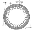
以下に、本実施形態の固定子50の詳細構造を図31から図35を用いて説明する。図31において、固定子50は、固定子コア52の外側に固定子巻線51を備えている。固定子巻線51は、コイルサイド部53とコイルエンド部54,55とを備えている。コイルサイド部53は、回転子40における磁石部42と対向しており、磁石部42に沿って軸方向に真っすぐに延びている。 Hereinafter, the detailed structure of the stator 50 of the present embodiment will be described with reference to FIGS. 31 to 35. In FIG. 31, the stator 50 includes a stator winding 51 on the outside of the stator core 52. The stator winding 51 includes a coil side portion 53 and coil end portions 54 and 55. The coil side portion 53 faces the magnet portion 42 of the rotor 40 and extends straight along the magnet portion 42 in the axial direction.

コイルエンド部54,55は、複数のターン部84が回転子40の磁石部42とは反対側に折り曲げられており、ターン部84同士が回転軸11の軸方向に重なっている。言い換えると、固定子巻線51は、固定子コア52に沿うようにコイルエンド部54,55が径方向内側に折り曲げられており、コイルエンド部54とコイルエンド部55とで固定子コア52を挟むように構成されている。 In the coil end portions 54 and 55, a plurality of turn portions 84 are bent on the side opposite to the magnet portion 42 of the rotor 40, and the turn portions 84 overlap each other in the axial direction of the rotation shaft 11. In other words, in the stator winding 51, the coil end portions 54 and 55 are bent inward in the radial direction along the stator core 52, and the stator core 52 is formed by the coil end portion 54 and the coil end portion 55. It is configured to sandwich.

コイルエンド部54,55の内、エンドプレート部63から遠い側に位置しているコイルエンド部54をなすターン部84の一部は、固定子コア52の内周面よりも回転軸11の径方向内側に位置している。言い換えると、コイルエンド部54をなすターン部84は、形状の異なるターン部84同士が径方向に互いにずれており、軸方向に互いに重なっている部分と重なっていない部分とが存在する。 Of the coil end portions 54 and 55, a part of the turn portion 84 forming the coil end portion 54 located on the side farther from the end plate portion 63 has a diameter of the rotating shaft 11 with respect to the inner peripheral surface of the stator core 52. It is located inside the direction. In other words, in the turn portion 84 forming the coil end portion 54, the turn portions 84 having different shapes are displaced from each other in the radial direction, and there are a portion that overlaps with each other in the axial direction and a portion that does not overlap with each other.

一方、コイルエンド部54,55の内、エンドプレート部63に近い側に位置しているコイルエンド部55をなすターン部84は、径方向への突出量が互いに等しい。言い換えると、コイルエンド部55をなすターン部84は、径方向に互いにずれておらず、コイルエンド部55の全体においてターン部84同士が軸方向に互いに重なっている部分がコイルエンド部54をなすターン部84に比べて多い。コイルエンド部55は、円環状の固定子コア52の内周面よりも回転軸11の径方向外側に位置している。コイルエンド部54とコイルエンド部55とは、互いに非対称な形状である。 On the other hand, among the coil end portions 54 and 55, the turn portions 84 forming the coil end portion 55 located closer to the end plate portion 63 have equal protrusion amounts in the radial direction. In other words, the turn portions 84 forming the coil end portion 55 are not displaced from each other in the radial direction, and the portion of the entire coil end portion 55 in which the turn portions 84 overlap each other in the axial direction forms the coil end portion 54. It is more than the turn part 84. The coil end portion 55 is located radially outside the rotating shaft 11 with respect to the inner peripheral surface of the annular stator core 52. The coil end portion 54 and the coil end portion 55 have asymmetrical shapes.

コイルエンド部54において径方向への突出量が大きい固定子巻線51は、コイルエンド部55において軸方向への突出量が小さい。一方、コイルエンド部54において径方向への突出量が小さい固定子巻線51は、コイルエンド部55において軸方向への突出量が大きい。すなわち、コイルエンド部54とコイルエンド部55とを合わせた固定子巻線51の長さは、互いに略等しい長さである。 The stator winding 51 having a large radial protrusion at the coil end 54 has a small axial protrusion at the coil end 55. On the other hand, the stator winding 51 having a small radial protrusion at the coil end 54 has a large axial protrusion at the coil end 55. That is, the lengths of the stator windings 51 including the coil end portion 54 and the coil end portion 55 are substantially equal to each other.

固定子コア52を径方向内側から保持しているケーシング部64は軸方向に延びる円筒形である。コイルエンド部55の径方向内側にはケーシング部64が位置している。言い換えると、コイルエンド部55側において、ケーシング部64は、固定子コア52よりも軸方向に長く突出して設けられている。一方、コイルエンド部54の径方向内側にはケーシング部64が位置していない。言い換えると、コイルエンド部54側において、ケーシング部64の軸方向における端部は、固定子コア52の軸方向における端部と面一であって、固定子コア52を基準とした軸方向への延出高さがゼロである。したがって、ケーシング部64は、コイルエンド部54側に比べてコイルエンド部55側の方が固定子コア52を基準とした軸方向への延出高さが高い。 The casing portion 64 that holds the stator core 52 from the inside in the radial direction has a cylindrical shape that extends in the axial direction. The casing portion 64 is located inside the coil end portion 55 in the radial direction. In other words, on the coil end portion 55 side, the casing portion 64 is provided so as to project longer in the axial direction than the stator core 52. On the other hand, the casing portion 64 is not located inside the coil end portion 54 in the radial direction. In other words, on the coil end 54 side, the axial end of the casing 64 is flush with the axial end of the stator core 52, in the axial direction with respect to the stator core 52. The extension height is zero. Therefore, the casing portion 64 has a higher extension height in the axial direction with respect to the stator core 52 on the coil end portion 55 side than on the coil end portion 54 side.

図32において、固定子50は、円環状の固定子コア52の外側にU相、V相、W相の3相分の固定子巻線51を備えている。すなわち、固定子巻線51は、U相の巻線であるU相固定子巻線51UとV相の巻線であるV相固定子巻線51VとW相の巻線であるW相固定子巻線51Wとの3種類の相巻線によって形成されている。本実施形態において、以降の説明ではコイルエンド部54側におけるターン部84とコイルエンド部55側におけるターン部84を区別する目的で、ターン部84の符号としてターン部841とターン部846との2つの符号を用いて説明を行う。すなわち、コイルエンド部54,55の内、エンドプレート部63から遠い側に位置するコイルエンド部54側のターン部84には、ターン部841の符号を付している。一方、コイルエンド部54,55の内、エンドプレート部63から近い側に位置しているコイルエンド部55側のターン部84には、ターン部846の符号を付している。 In FIG. 32, the stator 50 includes a stator winding 51 for three phases of U phase, V phase, and W phase on the outside of the annular stator core 52. That is, the stator winding 51 is a U-phase stator winding 51U which is a U-phase winding, a V-phase stator winding 51V which is a V-phase winding, and a W-phase stator which is a W-phase winding. It is formed by three types of phase windings with a winding 51W. In the present embodiment, in the following description, for the purpose of distinguishing the turn portion 84 on the coil end portion 54 side and the turn portion 84 on the coil end portion 55 side, the turn portion 841 and the turn portion 846 are designated as the symbols of the turn portion 84. The explanation will be given using one reference numeral. That is, of the coil end portions 54 and 55, the turn portion 84 on the coil end portion 54 side located on the side farther from the end plate portion 63 is designated by the turn portion 841. On the other hand, of the coil end portions 54 and 55, the turn portion 84 on the coil end portion 55 side located closer to the end plate portion 63 is designated by the turn portion 846.

ターン部841は、U相固定子巻線51Uにおけるターン部841であるU相ターン部841Uと、V相におけるターン部841であるV相ターン部841Vと、W相におけるターン部841であるW相ターン部841Wを備えている。ターン部846についてもターン部841と同様に、U相ターン部846UとV相ターン部846VとW相ターン部846Wとの3種類を有している。コイルサイド部53についてもターン部841と同様に、U相コイルサイド部53UとV相コイルサイド部53VとW相コイルサイド部53Wとの3種類を有している。 The turn portion 841 is a U-phase turn portion 841U which is a turn portion 841 in the U-phase stator winding 51U, a V-phase turn portion 841V which is a turn portion 841 in the V phase, and a W phase which is a turn portion 841 in the W phase. It has a turn portion 841W. Similar to the turn portion 841, the turn portion 846 also has three types of a U-phase turn portion 846U, a V-phase turn portion 846V, and a W-phase turn portion 846W. Similar to the turn portion 841, the coil side portion 53 also has three types: a U-phase coil side portion 53U, a V-phase coil side portion 53V, and a W-phase coil side portion 53W.

U相固定子巻線51Uは、U相コイルサイド部53UとU相ターン部841U、846Uとを備えている。V相固定子巻線51Vは、V相コイルサイド部53VとV相ターン部841V、846Vとを備えている。W相固定子巻線51Wは、W相コイルサイド部53WとW相ターン部841W、846Wとを備えている。 The U-phase stator winding 51U includes a U-phase coil side portion 53U and U-phase turn portions 841U and 846U. The V-phase stator winding 51V includes a V-phase coil side portion 53V and a V-phase turn portion 841V and 846V. The W-phase stator winding 51W includes a W-phase coil side portion 53W and W-phase turn portions 841W and 846W.

U相固定子巻線51UとV相固定子巻線51VとW相固定子巻線51Wとは、固定子コア52の外周面において同相の固定子巻線51同士が接触しないように周方向に所定数ごとに規則的に配置されている。すなわち、固定子50の周方向において、U相固定子巻線51Uに隣接して、V相固定子巻線51VとW相固定子巻線51Wとが配置されている。V相固定子巻線51Vに隣接して、U相固定子巻線51UとW相固定子巻線51Wとが配置されている。W相固定子巻線51Wに隣接して、U相固定子巻線51UとV相固定子巻線51Vとが配置されている。したがって、U相固定子巻線51U同士は、固定子50において周方向に等間隔に並んで設けられている。V相固定子巻線51V同士は、固定子50において周方向に等間隔に並んで設けられている。W相固定子巻線51W同士は、固定子50において周方向に等間隔に並んで設けられている。 The U-phase stator winding 51U, the V-phase stator winding 51V, and the W-phase stator winding 51W are arranged in the circumferential direction so that the in-phase stator windings 51 do not come into contact with each other on the outer peripheral surface of the stator core 52. It is regularly arranged in a predetermined number. That is, in the circumferential direction of the stator 50, the V-phase stator winding 51V and the W-phase stator winding 51W are arranged adjacent to the U-phase stator winding 51U. A U-phase stator winding 51U and a W-phase stator winding 51W are arranged adjacent to the V-phase stator winding 51V. A U-phase stator winding 51U and a V-phase stator winding 51V are arranged adjacent to the W-phase stator winding 51W. Therefore, the U-phase stator windings 51U are provided in the stator 50 at equal intervals in the circumferential direction. The V-phase stator windings 51V are provided side by side in the stator 50 at equal intervals in the circumferential direction. The W-phase stator windings 51W are provided in the stator 50 at equal intervals in the circumferential direction.

各相の固定子巻線51の導線82の長さに関して、ターン部841の最も長いU相固定子巻線51Uは、ターン部846が最も短い。一方、ターン部841の最も短いW相固定子巻線51Wは、ターン部846が最も長い。すなわち、U相固定子巻線51Uの導体長とV相固定子巻線51Vの導体長とW相固定子巻線51Wの導体長とは、互いに等しい長さである。また、U相固定子巻線51Uの太さとV相固定子巻線51Vの太さとW相固定子巻線51Wの太さとは、互いに等しい太さである。ただし、各相の固定子巻線51が厳密に等しい長さ及び太さである必要はなく、互いの固定子巻線51における抵抗値が同程度に揃う程度に等しい長さ及び太さであればよい。 Regarding the length of the lead wire 82 of the stator winding 51 of each phase, the longest U-phase stator winding 51U of the turn portion 841 has the shortest turn portion 846. On the other hand, the shortest W-phase stator winding 51W of the turn portion 841 has the longest turn portion 846. That is, the conductor length of the U-phase stator winding 51U, the conductor length of the V-phase stator winding 51V, and the conductor length of the W-phase stator winding 51W are equal to each other. Further, the thickness of the U-phase stator winding 51U, the thickness of the V-phase stator winding 51V, and the thickness of the W-phase stator winding 51W are equal to each other. However, the stator windings 51 of each phase do not have to have exactly the same length and thickness, and the length and thickness of the stator windings 51 of each phase must be equal to each other. Just do it.

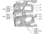
図33において、ターン部841をなす導線群81は、径方向に並ぶ4本の導線82によって構成されている。すなわち、U相ターン部841Uは、径方向外側から径方向内側に向かう向きに第1U相ターン部841U1、第2U相ターン部841U2、第3U相ターン部841U3、第4U相ターン部841U4の順に構成されている。U相ターン部841Uと同様に、V相ターン部841Vは、径方向外側から径方向内側に向かう向きに第1V相ターン部841V1、第2V相ターン部841V2、第3V相ターン部841V3、第4V相ターン部841V4の順に構成されている。U相ターン部841Uと同様に、W相ターン部841Wは、径方向外側から径方向内側に向かう向きに第1W相ターン部841W1、第2W相ターン部841W2、第3W相ターン部841W3、第4W相ターン部841W4の順に構成されている。導線群81と導線82とは、ともに導線部を提供する。 In FIG. 33, the conductor group 81 forming the turn portion 841 is composed of four conductors 82 arranged in the radial direction. That is, the U-phase turn portion 841U is configured in the order of the first U-phase turn portion 841U1, the second U-phase turn portion 841U2, the third U-phase turn portion 841U3, and the fourth U-phase turn portion 841U4 in the direction from the outer side in the radial direction to the inner side in the radial direction. Has been done. Similar to the U-phase turn portion 841U, the V-phase turn portion 841V has a first V-phase turn portion 841V1, a second V-phase turn portion 841V2, a third V-phase turn portion 841V3, and a fourth V in the direction from the outer side in the radial direction to the inner side in the radial direction. It is configured in the order of the phase turn portion 841V4. Similar to the U-phase turn portion 841U, the W-phase turn portion 841W has a first W-phase turn portion 841W1, a second W-phase turn portion 841W2, a third W-phase turn portion 841W3, and a fourth W in the direction from the outer side in the radial direction to the inner side in the radial direction. It is configured in the order of the phase turn portion 841W4. Both the conductor group 81 and the conductor 82 provide a conductor portion.

ターン部841をなす導線82は、径方向内側に延びる部分である2本の傾斜部841aと、周方向に延びる部分である頂部841bと、傾斜部841aと頂部841bとを接続する2つの角部841eを備えている。ターン部841は、径方向外側に開放端を有するU字状をなしている。 The conducting wire 82 forming the turn portion 841 has two inclined portions 841a extending inward in the radial direction, a top portion 841b extending in the circumferential direction, and two corner portions connecting the inclined portion 841a and the top portion 841b. It is equipped with 841e. The turn portion 841 has a U shape having an open end on the outer side in the radial direction.

ターン部841において、U相ターン部841Uは、V相ターン部841VやW相ターン部841Wよりも固定子コア52に近い軸方向内側に位置している。すなわち、U相ターン部841Uは、ターン部841のうち、最も内層に位置している最内層ターン部を提供する。 In the turn portion 841, the U-phase turn portion 841U is located on the inner side in the axial direction closer to the stator core 52 than the V-phase turn portion 841V and the W-phase turn portion 841W. That is, the U-phase turn portion 841U provides the innermost layer turn portion located in the innermost layer of the turn portions 841.

一方、V相ターン部841VとW相ターン部841Wとは、U相ターン部841Uよりも固定子コア52から遠い方向である軸方向外側に位置している。すなわち、V相ターン部841VとW相ターン部841Wとは、外層ターン部を提供する。さらに、外層ターン部であるW相ターン部841Wは、U相ターン部841UやV相ターン部841Vよりも軸方向外側に位置している。すなわち、W相ターン部841Wは、ターン部841のうち、最も外層に位置している最外層ターン部を提供する。さらに、外層ターン部であるV相ターン部841Vは、最内層ターン部であるU相ターン部841Uと最外層ターン部であるW相ターン部841Wとの間に位置している。すなわち、V相ターン部841Vは、ターン部841のうち、最内層と最外層との間の中層に位置している中層ターン部を提供する。 On the other hand, the V-phase turn portion 841V and the W-phase turn portion 841W are located on the outer side in the axial direction, which is a direction farther from the stator core 52 than the U-phase turn portion 841U. That is, the V-phase turn portion 841V and the W-phase turn portion 841W provide an outer layer turn portion. Further, the W-phase turn portion 841W, which is the outer layer turn portion, is located axially outside the U-phase turn portion 841U and the V-phase turn portion 841V. That is, the W-phase turn portion 841W provides the outermost layer turn portion located in the outermost layer of the turn portions 841. Further, the V-phase turn portion 841V, which is the outer layer turn portion, is located between the U-phase turn portion 841U, which is the innermost layer turn portion, and the W-phase turn portion 841W, which is the outermost layer turn portion. That is, the V-phase turn portion 841V provides a middle layer turn portion located in the middle layer between the innermost layer and the outermost layer of the turn portion 841.

図34において、最内層ターン部であるU相ターン部841Uについて、径方向最外側から径方向最内側までの距離であるU相ターン部841Uの最大突出量は、最内層最大突出量LUで示されている。中層ターン部であるV相ターン部841Vについて、径方向最外側から径方向最内側までの距離であるV相ターン部841Vの最大突出量は、中層最大突出量LVで示されている。最外層ターン部であるW相ターン部841Wについて、径方向最外側から径方向最内側までの距離であるW相ターン部841Wの最大突出量は、最外層最大突出量LWで示されている。 In FIG. 34, with respect to the U-phase turn portion 841U which is the innermost layer turn portion, the maximum protrusion amount of the U-phase turn portion 841U which is the distance from the outermost side in the radial direction to the innermost side in the radial direction is indicated by the maximum protrusion amount LU of the innermost layer. Has been done. Regarding the V-phase turn portion 841V which is the middle layer turn portion, the maximum protrusion amount of the V-phase turn portion 841V, which is the distance from the outermost radial direction to the innermost radial direction, is indicated by the maximum protrusion amount LV of the middle layer. With respect to the W-phase turn portion 841W, which is the outermost layer turn portion, the maximum protrusion amount of the W-phase turn portion 841W, which is the distance from the outermost radial direction to the innermost radial direction, is indicated by the maximum protrusion amount LW of the outermost layer.

最内層最大突出量LUは、中層最大突出量LVよりも大きい。最外層最大突出量LWは、中層最大突出量LVよりも小さい。すなわち、ターン部841における径方向の突出量は、最内層最大突出量LUが最も大きく、最外層最大突出量LWが最も小さい。 The maximum protrusion amount LU of the innermost layer is larger than the maximum protrusion amount LV of the middle layer. The maximum protrusion amount LW of the outermost layer is smaller than the maximum protrusion amount LV of the middle layer. That is, as for the radial protrusion amount of the turn portion 841, the innermost layer maximum protrusion amount LU is the largest, and the outermost layer maximum protrusion amount LW is the smallest.

ここで突出量とは、コイルサイド部53が位置している面である固定子コア52の外周面を基準として径方向に突出している長さを意味している。また、突出量は、ターン部841をなす導線82毎に決まる量であって、U相ターン部841Uにおいては、第1U相ターン部841U1と第2U相ターン部841U2と第3U相ターン部841U3と第4U相ターン部841U4とで、それぞれに異なる突出量を有する。最内層最大突出量LUは、第4U相ターン部841U4における突出量に等しい。中層最大突出量LVは、第4V相ターン部841V4における突出量に等しい。最外層最大突出量LWは、第4W相ターン部841W4における突出量に等しい。 Here, the protruding amount means a length that protrudes in the radial direction with reference to the outer peripheral surface of the stator core 52, which is the surface on which the coil side portion 53 is located. The amount of protrusion is determined for each conductor 82 forming the turn portion 841, and in the U-phase turn portion 841U, the first U-phase turn portion 841U1, the second U-phase turn portion 841U2, and the third U-phase turn portion 841U3. The fourth U-phase turn portion 841U4 and the fourth U-phase turn portion 841U4 have different protrusion amounts. The maximum protrusion amount LU of the innermost layer is equal to the protrusion amount in the fourth U phase turn portion 841U4. The maximum protrusion amount LV of the middle layer is equal to the protrusion amount in the fourth V phase turn portion 841V4. The maximum protrusion amount LW of the outermost layer is equal to the protrusion amount in the fourth W phase turn portion 841W4.

図33において、U相ターン部841Uにおける第2U相ターン部841U2の径方向への突出量は、固定子コア52の径方向の厚さ寸法と略等しい大きさである。第1U相ターン部841U1の径方向の突出量は、第1U相ターン部841U1の厚さ分だけ第2U相ターン部841U2よりも小さい。 In FIG. 33, the radial protrusion amount of the second U-phase turn portion 841U2 in the U-phase turn portion 841U is substantially equal to the radial thickness dimension of the stator core 52. The radial protrusion amount of the first U phase turn portion 841U1 is smaller than that of the second U phase turn portion 841U2 by the thickness of the first U phase turn portion 841U1.

第3U相ターン部841U3の径方向への突出量は、固定子コア52の径方向の厚さ寸法の2倍程度の大きさである。すなわち、第3U相ターン部841U3の径方向への突出量は、固定子コア52の厚さ寸法よりも大きい。したがって、U相ターン部841Uの少なくとも一部は、固定子コア52の内周面よりも径方向の内側まで突出している。第4U相ターン部841U4の径方向の突出量は、第4U相ターン部841U4の厚さ分だけ第3U相ターン部841U3よりも大きい。 The radial protrusion amount of the third U-phase turn portion 841U3 is about twice the radial thickness dimension of the stator core 52. That is, the amount of protrusion of the third U-phase turn portion 841U3 in the radial direction is larger than the thickness dimension of the stator core 52. Therefore, at least a part of the U-phase turn portion 841U protrudes inward in the radial direction from the inner peripheral surface of the stator core 52. The radial protrusion amount of the 4th U phase turn portion 841U4 is larger than that of the 3rd U phase turn portion 841U3 by the thickness of the 4U phase turn portion 841U4.

第2U相ターン部841U2の径方向への突出量は、第3U相ターン部841U3の径方向への突出量よりも小さい。すなわち、第1U相ターン部841U1と第2U相ターン部841U2とは、突出量の小さな小ターン部を提供する。一方、第3U相ターン部841U3と第4U相ターン部841U4とは、突出量の大きな大ターン部を提供する。 The radial protrusion amount of the second U-phase turn portion 841U2 is smaller than the radial protrusion amount of the third U-phase turn portion 841U3. That is, the first U-phase turn portion 841U1 and the second U-phase turn portion 841U2 provide a small turn portion having a small protrusion amount. On the other hand, the third U-phase turn portion 841U3 and the fourth U-phase turn portion 841U4 provide a large turn portion having a large protrusion amount.

U相ターン部841Uと同様にV相ターン部841Vは、第1V相ターン部841V1と第2V相ターン部841V2とは、小ターン部であり、第3V相ターン部841V3と第4V相ターン部841V4とは、大ターン部である。ただし、V相ターン部841Vの大ターン部である第3V相ターン部841V3と第4V相ターン部841V4との径方向への突出量は、第3U相ターン部841U3と第4U相ターン部841U4との径方向への突出量に比べて小さい。一方、第2V相ターン部841V2の径方向への突出量は、第2U相ターン部841U2の径方向への突出量と略等しい大きさである。 Similar to the U-phase turn section 841U, the V-phase turn section 841V has a first V-phase turn section 841V1 and a second V-phase turn section 841V2, which are small turn sections, and the third V-phase turn section 841V3 and the fourth V-phase turn section 841V4. Is the big turn part. However, the amount of radial protrusion of the third V-phase turn portion 841V3 and the fourth V-phase turn portion 841V4, which are the large turn portions of the V-phase turn portion 841V, is the same as that of the third U-phase turn portion 841U3 and the fourth U-phase turn portion 841U4. It is smaller than the amount of protrusion in the radial direction of. On the other hand, the radial protrusion amount of the second V-phase turn portion 841V2 is substantially equal to the radial protrusion amount of the second U-phase turn portion 841U2.

大ターン部と小ターン部との間には空隙が形成されている。すなわち、第2U相ターン部841U2と第3U相ターン部841U3とは、互いに径方向に離隔しており、第2U相ターン部841U2と第3U相ターン部841U3との間に空隙が形成されている。また、第2V相ターン部841V2と第3V相ターン部841V3との間にも空隙が形成されている。V相ターン部841Vにおける第2V相ターン部841V2と第3V相ターン部841V3との間の空隙の大きさは、U相ターン部841Uにおける第2U相ターン部841U2と第3U相ターン部841U3との間の空隙の大きさよりも小さい。 A gap is formed between the large turn portion and the small turn portion. That is, the second U-phase turn portion 841U2 and the third U-phase turn portion 841U3 are separated from each other in the radial direction, and a gap is formed between the second U-phase turn portion 841U2 and the third U-phase turn portion 841U3. .. Further, a gap is also formed between the second V-phase turn portion 841V2 and the third V-phase turn portion 841V3. The size of the gap between the second V-phase turn portion 841V2 and the third V-phase turn portion 841V3 in the V-phase turn portion 841V is the same as that of the second U-phase turn portion 841U2 and the third U-phase turn portion 841U3 in the U-phase turn portion 841U. It is smaller than the size of the gap between them.

W相ターン部841Wにおいては、第2W相ターン部841W2の突出量と第3W相ターン部841W3の突出量とが、導線82の厚さ分程度異なる。すなわち、第2W相ターン部841W2と第3W相ターン部841W3との間に形成される隙間が極めて小さい。言い換えると、W相ターン部841Wにおける第2W相ターン部841W2と第3W相ターン部841W3との間の空隙の大きさは、V相ターン部841Vにおける第2V相ターン部841V2と第3V相ターン部841V3との間の空隙の大きさよりも小さい。 In the W-phase turn portion 841W, the amount of protrusion of the second W-phase turn portion 841W2 and the amount of protrusion of the third W-phase turn portion 841W3 differ by about the thickness of the conducting wire 82. That is, the gap formed between the second W phase turn portion 841W2 and the third W phase turn portion 841W3 is extremely small. In other words, the size of the gap between the second W phase turn portion 841W2 and the third W phase turn portion 841W3 in the W phase turn portion 841W is the size of the second V phase turn portion 841V2 and the third V phase turn portion in the V phase turn portion 841V. It is smaller than the size of the gap between 841V3.

図35において、小ターン部である第2V相ターン部841V2の角部841eの曲げ外側における曲率半径Raと、大ターン部である第3V相ターン部841V3の角部841eの曲げ内側における曲率半径Rbとは異なる大きさである。曲率半径Raは、第2V相ターン部841V2における2箇所の角部841eの曲げ外側において同じ大きさである。曲率半径Rbは、第3V相ターン部841V3における2箇所の角部841eの曲げ内側において同じ大きさである。曲率半径Raと曲率半径Rbとを規定する角部841eは互いに対向している。ここで、仮に第2V相ターン部841V2と第3V相ターン部841V3との間に空隙が形成されておらず、導線82が互いに隙間なく接触している場合を想定すると、曲率半径Raと曲率半径Rbは等しい大きさとなる。すなわち、V相ターン部841Vにおいては、曲率半径Raと曲率半径Rbとの大きさを変えることで、第2V相ターン部841V2と第3V相ターン部841V3との間に空隙を生じさせている。 In FIG. 35, the radius of curvature Ra on the outside of the bend of the corner portion 841e of the second V-phase turn portion 841V2 which is the small turn portion and the radius of curvature Rb on the inside of the bend of the corner portion 841e of the third V-phase turn portion 841V3 which is the large turn portion. It is a different size from. The radius of curvature Ra has the same magnitude on the bent outer side of the two corner portions 841e in the second V-phase turn portion 841V2. The radius of curvature Rb has the same magnitude inside the bending of the two corner portions 841e in the third V-phase turn portion 841V3. The corner portions 841e that define the radius of curvature Ra and the radius of curvature Rb face each other. Here, assuming that a gap is not formed between the second V-phase turn portion 841V2 and the third V-phase turn portion 841V3 and the conducting wires 82 are in contact with each other without a gap, the radius of curvature Ra and the radius of curvature are assumed. Rb has the same magnitude. That is, in the V-phase turn portion 841V, a gap is generated between the second V-phase turn portion 841V2 and the third V-phase turn portion 841V3 by changing the magnitudes of the radius of curvature Ra and the radius of curvature Rb.

V相ターン部841Vにおいて、曲率半径Raは、曲率半径Rbよりも大きい。すなわち、第2V相ターン部841V2は、第3V相ターン部841V3に比べて緩やかな曲線を描くように曲げられている。これにより、V相ターン部841Vにおいて、空隙を形成するとともに、4本の導線82を無理なく曲げてターンさせることができる。U相ターン部841Uにおいても、V相ターン部841Vと同様に第2U相ターン部841U2は、第3U相ターン部841U3に比べて緩やかな曲線を描くように大きな曲率半径で曲げられている。 At the V-phase turn portion 841V, the radius of curvature Ra is larger than the radius of curvature Rb. That is, the second V-phase turn portion 841V2 is bent so as to draw a gentle curve as compared with the third V-phase turn portion 841V3. As a result, in the V-phase turn portion 841V, a gap can be formed and the four conducting wires 82 can be bent and turned without difficulty. In the U-phase turn portion 841U as well, the second U-phase turn portion 841U2 is bent with a large radius of curvature so as to draw a gentle curve as compared with the third U-phase turn portion 841U3, similarly to the V-phase turn portion 841V.

第1U相ターン部841U1における径方向への突出量と、第1V相ターン部841V1における径方向への突出量とは、等しい大きさである。第2U相ターン部841U2における径方向への突出量と、第2V相ターン部841V2における径方向への突出量とは、等しい大きさである。第4W相ターン部841W4の突出量は、第1V相ターン部841V1の突出量よりも小さい。したがって、W相ターン部841Wにおける頂部841bは、U相ターン部841Uにおける頂部841b及びV相ターン部841Vにおける頂部841bと径方向にずれた位置に設けられている。言い換えると、W相ターン部841Wの頂部841bは他のターン部841における頂部841bとは軸方向に重なっていない。 The radial protrusion amount of the first U-phase turn portion 841U1 and the radial protrusion amount of the first V-phase turn portion 841V1 are equal in magnitude. The radial protrusion amount of the second U-phase turn portion 841U2 and the radial protrusion amount of the second V-phase turn portion 841V2 are equal in magnitude. The amount of protrusion of the fourth W phase turn portion 841W4 is smaller than the amount of protrusion of the first V phase turn portion 841V1. Therefore, the top portion 841b in the W-phase turn portion 841W is provided at a position radially deviated from the top portion 841b in the U-phase turn portion 841U and the top portion 841b in the V-phase turn portion 841V. In other words, the top 841b of the W-phase turn 841W does not axially overlap the top 841b of the other turn 841.

コイルエンド部54における放熱について以下に説明する。固定子巻線51には通電に伴い発熱が生じる。この発熱により固定子巻線51の温度が上昇する。ただし、固定子巻線51の温度が上昇するほど、固定子巻線51の周囲の空気との温度差が大きくなるため、固定子巻線51の熱が積極的に空気中に放熱される。ここで、固定子巻線51と周囲の空気との接触面積の大きさによって固定子巻線51から空気に放熱される放熱量が変化する。すなわち、固定子巻線51のうち、空気との接触面積が大きい部分については、固定子巻線51の熱が積極的に空気中に放熱されて温度が上昇しにくい。一方、固定子巻線51のうち、空気との接触面積が小さい部分については、空気中に放熱されにくく、熱がこもって温度が上昇しやすい。したがって、固定子巻線51からの放熱性能を高めるためには、温度の低い空気と固定子巻線51とをなるべく多く接触させることが必要となる。 The heat dissipation in the coil end portion 54 will be described below. Heat is generated in the stator winding 51 as it is energized. This heat generation raises the temperature of the stator winding 51. However, as the temperature of the stator winding 51 rises, the temperature difference from the air around the stator winding 51 increases, so that the heat of the stator winding 51 is positively dissipated into the air. Here, the amount of heat radiated from the stator winding 51 to the air changes depending on the size of the contact area between the stator winding 51 and the surrounding air. That is, in the portion of the stator winding 51 having a large contact area with air, the heat of the stator winding 51 is positively dissipated into the air, and the temperature is unlikely to rise. On the other hand, in the portion of the stator winding 51 having a small contact area with air, it is difficult for heat to be dissipated into the air, and heat tends to be trapped and the temperature tends to rise. Therefore, in order to improve the heat dissipation performance from the stator winding 51, it is necessary to bring the air having a low temperature into contact with the stator winding 51 as much as possible.

コイルエンド部54は、最内層ターン部であるU相ターン部841Uと、中層ターン部であるV相ターン部841Vと、最外層ターン部であるW相ターン部841Wとの3種類のターン部841によって構成されている。ここで、仮にU相ターン部841UとV相ターン部841VとW相ターン部841Wとの3種類のターン部841が、互いに径方向にずれておらず、径方向への突出量が互いに等しい場合を想定する。この場合には、最外層ターン部であるW相ターン部841Wの外側には、空気との接触を妨げる部材がなく、他のターン部841に比べて空気との接触面積が大きく放熱性能が高い。一方、最内層ターン部であるU相ターン部841Uは、内側に固定子コア52が配置されるとともに、外側に中層ターン部であるV相ターン部841Vと最外層ターン部であるW相ターン部841Wとが配置されることとなる。このため、U相ターン部841Uの内側と外側との両側において、空気との接触を妨げる部材が存在することとなる。したがって、U相ターン部841Uは、少なくともW相ターン部841Wよりも放熱性能が低くなりやすい。 The coil end portion 54 has three types of turn portions 841: a U-phase turn portion 841U which is the innermost layer turn portion, a V-phase turn portion 841V which is a middle layer turn portion, and a W-phase turn portion 841W which is an outermost layer turn portion. It is composed of. Here, if the three types of turn portions 841 of the U-phase turn portion 841U, the V-phase turn portion 841V, and the W-phase turn portion 841W are not displaced in the radial direction from each other and the protrusion amounts in the radial direction are equal to each other. Is assumed. In this case, there is no member that hinders contact with air on the outside of the W-phase turn portion 841W, which is the outermost layer turn portion, and the contact area with air is larger and the heat dissipation performance is higher than that of the other turn portions 841. .. On the other hand, in the U-phase turn portion 841U which is the innermost layer turn portion, the stator core 52 is arranged inside, and the V-phase turn portion 841V which is the middle layer turn portion and the W-phase turn portion which is the outermost layer turn portion are arranged on the outside. 841W will be arranged. Therefore, on both the inside and outside of the U-phase turn portion 841U, there are members that prevent contact with air. Therefore, the U-phase turn portion 841U tends to have lower heat dissipation performance than at least the W-phase turn portion 841W.

しかしながら、ターン部841においては、U相ターン部841Uの径方向への突出量と、V相ターン部841Vの径方向への突出量と、W相ターン部841Wの径方向への突出量とが互いに異なる突出量である。言い換えると、U相ターン部841UとV相ターン部841VとW相ターン部841Wとの3種類のターン部841が、互いに径方向にずれて配置されている。このため、最内層ターン部であるU相ターン部841Uの少なくとも一部においては、外側に他のターン部841が配置されていない部分となる。中層ターン部であるV相ターン部841Vについても同様に、外側に他のターン部841が配置されていない部分が存在する。したがって、最内層ターン部であるU相ターン部841Uと中層ターン部であるV相ターン部841Vとは、空気中への放熱が促進された部分を有する放熱促進ターン部841を提供している。また、W相ターン部841Wについても、軸方向に他のターン部841と重なる量が少ない。言い換えると、W相ターン部841Wの軸方向内側における空気との接触面積が大きい。したがって、W相ターン部841Wは、放熱の促進された放熱促進ターン部841を提供している。 However, in the turn portion 841, the radial protrusion amount of the U-phase turn portion 841U, the radial protrusion amount of the V-phase turn portion 841V, and the radial protrusion amount of the W-phase turn portion 841W are different. The amount of protrusion is different from each other. In other words, three types of turn portions 841 of the U-phase turn portion 841U, the V-phase turn portion 841V, and the W-phase turn portion 841W are arranged so as to be radially offset from each other. Therefore, at least a part of the U-phase turn portion 841U, which is the innermost turn portion, is a portion in which another turn portion 841 is not arranged on the outside. Similarly, the V-phase turn portion 841V, which is the middle layer turn portion, also has a portion on the outside where no other turn portion 841 is arranged. Therefore, the U-phase turn portion 841U, which is the innermost layer turn portion, and the V-phase turn portion 841V, which is the middle layer turn portion, provide a heat dissipation promotion turn portion 841 having a portion in which heat dissipation to the air is promoted. Further, the amount of the W-phase turn portion 841W that overlaps with the other turn portions 841 in the axial direction is small. In other words, the contact area with air inside the W-phase turn portion 841W in the axial direction is large. Therefore, the W-phase turn portion 841W provides a heat dissipation promotion turn portion 841 in which heat dissipation is promoted.

さらに、U相ターン部841Uをなす第2U相ターン部841U2と第3U相ターン部841U3との間には空隙が形成されている。仮に、第2U相ターン部841U2と第3U相ターン部841U3との間に空隙が形成されていないと仮定する。この場合には、U相ターン部841Uの周囲を流れる空気がU相ターン部841Uをなす4本の導線82の間に入り込むことができない。すなわち、第2U相ターン部841U2と第3U相ターン部841U3とが互いに接触している面積をU相ターン部841Uと空気との接触面積に含むことができない。しかしながら、U相ターン部841Uにおいて、第2U相ターン部841U2と第3U相ターン部841U3との間に空隙が形成されている。このため、第2U相ターン部841U2と第3U相ターン部841U3との間に空気が入り込むことができる。すなわち、第2U相ターン部841U2と第3U相ターン部841U3とが互いに向かい合う部分の面積をU相ターン部841Uと空気との接触面積に含むことができる。したがって、U相ターン部841Uにおける空気との接触面積を大きく確保しやすい。 Further, a gap is formed between the second U-phase turn portion 841U2 forming the U-phase turn portion 841U and the third U-phase turn portion 841U3. It is assumed that no gap is formed between the second U-phase turn portion 841U2 and the third U-phase turn portion 841U3. In this case, the air flowing around the U-phase turn portion 841U cannot enter between the four conducting wires 82 forming the U-phase turn portion 841U. That is, the area in which the second U-phase turn portion 841U2 and the third U-phase turn portion 841U3 are in contact with each other cannot be included in the contact area between the U-phase turn portion 841U and air. However, in the U-phase turn portion 841U, a gap is formed between the second U-phase turn portion 841U2 and the third U-phase turn portion 841U3. Therefore, air can enter between the second U-phase turn portion 841U2 and the third U-phase turn portion 841U3. That is, the area of the portion where the second U-phase turn portion 841U2 and the third U-phase turn portion 841U3 face each other can be included in the contact area between the U-phase turn portion 841U and the air. Therefore, it is easy to secure a large contact area with air in the U-phase turn portion 841U.

図31において、回転子40が回転することで回転電機10の内部に風が発生する。発生した風の一部は、回転子40の内側に位置している固定子50に沿って流れる。この時、コイルエンド部54,55においては、風の流れ方が部位によって異なる。すなわち、固定子コア52を保持しているケーシング部64が、軸方向に大きく延び出しているコイルエンド部55の方が風の通路が制限されており、風が流れにくい。一方、コイルエンド部54は、コイルエンド部55に比べて風の流れを妨げる部材が少なく、多くの風が流れやすい。したがって、エンドプレート部63から近い側のコイルエンド部55に比べて、エンドプレート部63から遠い側のコイルエンド部54の方が固定子巻線51の放熱性能の向上に貢献しやすい。言い換えると、コイルエンド部55をなすターン部846の形状を放熱性能の高い形状とするよりも、コイルエンド部54をなすターン部841の形状を放熱性能の高い形状とする方が、固定子巻線51全体における放熱性能を高めることができる。ただし、ターン部841、846の両方について放熱性能の高い形状とする方が、ターン部841、846のどちらか一方のみについて放熱性能の高い形状とする場合に比べて、固定子巻線51全体における放熱性能を高めやすい。 In FIG. 31, the rotation of the rotor 40 causes wind to be generated inside the rotary electric machine 10. A part of the generated wind flows along the stator 50 located inside the rotor 40. At this time, in the coil end portions 54 and 55, the way the wind flows differs depending on the portion. That is, the coil end portion 55 in which the casing portion 64 holding the stator core 52 extends greatly in the axial direction has more restricted air passages, and the wind is less likely to flow. On the other hand, the coil end portion 54 has fewer members that obstruct the flow of wind than the coil end portion 55, and a large amount of wind is likely to flow. Therefore, the coil end portion 54 on the side farther from the end plate portion 63 is more likely to contribute to the improvement of the heat dissipation performance of the stator winding 51 than the coil end portion 55 on the side closer to the end plate portion 63. In other words, it is better to make the shape of the turn portion 841 forming the coil end portion 54 into a shape having high heat dissipation performance than to make the shape of the turn portion 846 forming the coil end portion 55 a shape having high heat dissipation performance. The heat dissipation performance of the entire wire 51 can be improved. However, it is better to have a shape having high heat dissipation performance for both the turn portions 841 and 846 than to have a shape having high heat dissipation performance for only one of the turn portions 841 and 846 in the entire stator winding 51. It is easy to improve heat dissipation performance.

上述した実施形態によると、最内層ターン部であるU相ターン部841Uの径方向への突出量は、外層ターン部であるV相ターン部841V及びW相ターン部841Wの径方向への突出量とは異なる突出量である。言い換えると、U相ターン部841Uは、V相ターン部841V及びW相ターン部841Wと軸方向に重ならない部分を多く有している。このため、U相ターン部841Uが他のターン部841と軸方向に重なっている場合に比べて、空気との接触面積をより大きく確保できるとともに、近傍における回転子40の回転により発生した風の通りも良くなるため、U相ターン部841Uにおける空気中への放熱を促進できる。また、V相ターン部841VやW相ターン部841Wにおいても、U相ターン部841Uと同様に空気中への放熱を促進できる。したがって、ターン部841における異常な温度上昇を抑制して回転電機10の適正な性能を発揮させやすい。特に、ターン部841のうち、最も熱のこもりやすい最内層に位置しているU相ターン部841Uにおける空気中への放熱を促進することは、回転電機10を適正に動作させる上で非常に重要である。 According to the above-described embodiment, the radial protrusion amount of the U-phase turn portion 841U, which is the innermost layer turn portion, is the radial protrusion amount of the V-phase turn portion 841V and the W-phase turn portion 841W, which are the outer layer turn portions. The amount of protrusion is different from. In other words, the U-phase turn portion 841U has many portions that do not overlap with the V-phase turn portion 841V and the W-phase turn portion 841W in the axial direction. Therefore, as compared with the case where the U-phase turn portion 841U overlaps with the other turn portions 841 in the axial direction, a larger contact area with air can be secured, and the wind generated by the rotation of the rotor 40 in the vicinity can be secured. Since the passage is improved, heat dissipation to the air at the U-phase turn portion 841U can be promoted. Further, the V-phase turn portion 841V and the W-phase turn portion 841W can also promote heat dissipation into the air in the same manner as the U-phase turn portion 841U. Therefore, it is easy to suppress an abnormal temperature rise in the turn portion 841 and bring out the proper performance of the rotary electric machine 10. In particular, it is very important for the rotary electric machine 10 to operate properly to promote heat dissipation to the air in the U-phase turn portion 841U located in the innermost layer of the turn portion 841 where heat is most likely to be trapped. Is.

U相ターン部841Uは、第2U相ターン部841U2などの小ターン部と第3U相ターン部841U3などの大ターン部との間に空隙を備えている。このため、U相ターン部841Uの周囲を流れる空気とU相ターン部841Uとの接触面積を大きく確保することができる。したがって、U相ターン部841Uにおける放熱性能を高めることができる。また、V相ターン部841VやW相ターン部841Wにおいても、U相ターン部841Uと同様に空隙を設けることで空気中への放熱を促進できる。 The U-phase turn portion 841U is provided with a gap between a small turn portion such as the second U-phase turn portion 841U2 and a large turn portion such as the third U-phase turn portion 841U3. Therefore, a large contact area between the air flowing around the U-phase turn portion 841U and the U-phase turn portion 841U can be secured. Therefore, the heat dissipation performance in the U-phase turn portion 841U can be improved. Further, also in the V-phase turn portion 841V and the W-phase turn portion 841W, heat dissipation to the air can be promoted by providing a gap as in the U-phase turn portion 841U.

最内層ターン部であるU相ターン部841Uにおける空隙は、外層ターン部であるV相ターン部841V及びW相ターン部841Wにおける空隙よりも大きい。このため、最も熱のこもりやすい最内層に位置しているU相ターン部841Uにおける放熱性能を高めて、U相固定子巻線51Uにおける温度が他の固定子巻線51の温度に比べて、高くなり過ぎることを防止しやすい。 The voids in the U-phase turn portion 841U, which is the innermost layer turn portion, are larger than the voids in the V-phase turn portion 841V and the W-phase turn portion 841W, which are the outer layer turn portions. Therefore, the heat dissipation performance of the U-phase turn portion 841U located in the innermost layer where heat is most likely to be trapped is improved, and the temperature of the U-phase stator winding 51U is higher than that of the other stator windings 51. It is easy to prevent it from becoming too high.

小ターン部である第2V相ターン部841V2の角部841eにおける曲率半径Raは、大ターン部である第3V相ターン部841V3の角部841eにおける曲率半径Rbよりも大きい。このため、V相ターン部841Vにおいて、第2V相ターン部841V2と第3V相ターン部841V3との間に空隙を形成しやすい。すなわち、複数の導線82を折り曲げて構成されているターン部841において、導線82を無理なくターンさせられるとともに、角部841eに過度な負荷が加わることを抑制して、適正にターンした状態を維持しやすい。 The radius of curvature Ra at the corner portion 841e of the second V-phase turn portion 841V2, which is the small turn portion, is larger than the radius of curvature Rb at the corner portion 841e of the third V-phase turn portion 841V3, which is the large turn portion. Therefore, in the V-phase turn portion 841V, a gap is likely to be formed between the second V-phase turn portion 841V2 and the third V-phase turn portion 841V3. That is, in the turn portion 841 formed by bending a plurality of conductor wires 82, the conductor wires 82 can be turned reasonably, and an excessive load is suppressed from being applied to the corner portion 841e to maintain a properly turned state. It's easy to do.

軸方向の両側に設けられているターン部84のうち、一方のみが放熱促進ターン部841である。言い換えると、軸方向の両側に設けられたターン部84は、互いに非対称な形状である。このため、ターン部84の両側を放熱促進ターン部841とする場合に比べて、固定子50の向きを認識しやすい。したがって、回転電機10を構成する各部品を組み付ける際に、部品の向きを誤って組み付けてしまうことを防止しやすい。また、固定子巻線51の設計自由度を高く確保することができる。 Of the turn portions 84 provided on both sides in the axial direction, only one is the heat dissipation promotion turn portion 841. In other words, the turn portions 84 provided on both sides in the axial direction are asymmetrical in shape. Therefore, it is easier to recognize the orientation of the stator 50 as compared with the case where both sides of the turn portion 84 are the heat dissipation promoting turn portions 841. Therefore, when assembling each component constituting the rotary electric machine 10, it is easy to prevent the components from being assembled in the wrong direction. Further, it is possible to secure a high degree of freedom in designing the stator winding 51.

放熱促進ターン部841は、固定子コア52の軸方向両側のターン部84のうち、ケーシング部64において固定子コア52よりも軸方向外側となる部分の延出高さが小さい側のターン部841に設けられている。このため、ケーシング部64によって空気の流れが阻害されにくいターン部841において、放熱を促進できる。したがって、同種の放熱促進ターン部841を、ターン部841とは反対側のターン部846側に設けた場合に比べて、より大きな放熱促進効果を得やすい。 The heat dissipation promotion turn portion 841 is a turn portion 841 on the side of the turn portions 84 on both sides in the axial direction of the stator core 52, which has a smaller extension height in the casing portion 64 in the axial direction than the stator core 52. It is provided in. Therefore, heat dissipation can be promoted in the turn portion 841 in which the air flow is not easily obstructed by the casing portion 64. Therefore, a larger heat dissipation promoting effect can be easily obtained as compared with the case where the same type of heat dissipation promoting turn portion 841 is provided on the turn portion 846 side opposite to the turn portion 841.

U相固定子巻線51Uの抵抗値とV相固定子巻線51Vの抵抗値とW相固定子巻線51Wの抵抗値とが、互いに等しい大きさである。すなわち、異相の固定子巻線51同士の導体長及び太さが互いに等しい長さである。このため、異相の固定子巻線51同士の抵抗値を互いに揃えて、導線82に通電をした場合における異相の固定子巻線51同士の発熱量を同程度とすることができる。したがって、特定の固定子巻線51の発熱量のみが異常に大きく、固定子巻線51の特定部位が異常な高温になることを抑制しやすい。 The resistance value of the U-phase stator winding 51U, the resistance value of the V-phase stator winding 51V, and the resistance value of the W-phase stator winding 51W are equal to each other. That is, the conductor lengths and thicknesses of the different-phase stator windings 51 are equal to each other. Therefore, the resistance values of the different-phase stator windings 51 can be made uniform with each other, and the amount of heat generated by the different-phase stator windings 51 when the conducting wire 82 is energized can be made to be about the same. Therefore, only the calorific value of the specific stator winding 51 is abnormally large, and it is easy to prevent the specific portion of the stator winding 51 from becoming abnormally high temperature.

最内層ターン部であるU相ターン部841Uにおける径方向への最内層最大突出量LUは、V相ターン部841Vにおける径方向への中層最大突出量LV及びW相ターン部841Wにおける径方向への最外層最大突出量LWよりも大きい。このため、U相ターン部841Uにおける頂部841bだけでなく、傾斜部841aでも放熱を促進できる。したがって、最も熱のこもりやすい最内層に位置しているU相ターン部841Uにおける放熱性能を高めやすい。 The innermost layer maximum protrusion amount LU in the radial direction in the U-phase turn portion 841U, which is the innermost layer turn portion, is the radial maximum protrusion amount LV in the V-phase turn portion 841V and the radial direction in the W-phase turn portion 841W. It is larger than the maximum protrusion amount LW of the outermost layer. Therefore, heat dissipation can be promoted not only at the top portion 841b of the U-phase turn portion 841U but also at the inclined portion 841a. Therefore, it is easy to improve the heat dissipation performance in the U-phase turn portion 841U located in the innermost layer where heat is most likely to be trapped.

V相ターン部841Vにおける径方向への中層最大突出量LVは、W相ターン部841Wにおける径方向への最外層最大突出量LWよりも大きい。さらに、U相ターン部841Uにおける径方向への最内層最大突出量LUは、V相ターン部841Vにおける径方向への中層最大突出量LVよりも大きい。言い換えると、熱のこもりやすい順に放熱促進ターン部841の径方向への突出量を大きく設定している。このため、熱のこもりやすい軸方向内側に位置している固定子巻線51ほど、放熱促進ターン部841での放熱性能を向上させることで、固定子巻線51全体において部位ごとの温度差が大きくなり過ぎることを抑制できる。 The radial maximum protrusion amount LV of the V-phase turn portion 841V is larger than the radial maximum protrusion amount LW of the W-phase turn portion 841W. Further, the radial maximum protrusion amount LU of the U-phase turn portion 841U is larger than the radial maximum protrusion amount LV of the V-phase turn portion 841V. In other words, the amount of protrusion of the heat dissipation promotion turn portion 841 in the radial direction is set larger in the order in which heat is likely to be trapped. Therefore, the stator winding 51 located on the inner side in the axial direction, which tends to retain heat, improves the heat dissipation performance at the heat dissipation promotion turn portion 841, so that the temperature difference between the parts of the entire stator winding 51 can be increased. It is possible to prevent it from becoming too large.

放熱促進ターン部841をなすU相ターン部841Uにおける最内層最大突出量LUは、固定子コア52の厚さ寸法よりも大きい。このため、U相ターン部841Uの軸方向内側において固定子コア52が位置することによって空気が流れにくくなることを抑制できる。したがって、U相ターン部841Uの軸方向外側と軸方向内側との両面において積極的に空気が流れる構成としやすい。よって、U相ターン部841Uにおける放熱性能を高めやすい。 The maximum protrusion amount LU of the innermost layer in the U-phase turn portion 841U forming the heat dissipation promotion turn portion 841 is larger than the thickness dimension of the stator core 52. Therefore, it is possible to prevent the air from becoming difficult to flow due to the position of the stator core 52 inside the U-phase turn portion 841U in the axial direction. Therefore, it is easy to configure the U-phase turn portion 841U so that air actively flows on both the outer side in the axial direction and the inner side in the axial direction. Therefore, it is easy to improve the heat dissipation performance in the U-phase turn portion 841U.

U相ターン部841Uにおいて、第2U相ターン部841U2と第3U相ターン部841U3との間以外に空隙を形成してもよい。例えば、第1U相ターン部841U1と第2U相ターン部841U2との間に空隙を形成してもよい。さらに、第3U相ターン部841U3と第4U相ターン部841U4との間に空隙を形成するなどしてU相ターン部841Uに複数の空隙を形成してもよい。これによると、U相ターン部841Uにおける空隙の数を多く確保できる。すなわち、サイズの大きな1つの空隙を形成するかわりに、サイズの小さな3つの空隙を形成することでU相ターン部841Uにおける空隙の大きさを大きく確保することができる。したがって、U相ターン部841Uにおける放熱性能を高めることができる。ここで、空隙を複数形成することは、U相ターン部841U以外のターン部841にも適用可能である。 In the U-phase turn portion 841U, a gap may be formed other than between the second U-phase turn portion 841U2 and the third U-phase turn portion 841U3. For example, a gap may be formed between the first U phase turn portion 841U1 and the second U phase turn portion 841U2. Further, a plurality of voids may be formed in the U-phase turn portion 841U by forming a gap between the third U-phase turn portion 841U3 and the fourth U-phase turn portion 841U4. According to this, a large number of voids in the U-phase turn portion 841U can be secured. That is, instead of forming one void having a large size, it is possible to secure a large size of the void in the U-phase turn portion 841U by forming three voids having a small size. Therefore, the heat dissipation performance in the U-phase turn portion 841U can be improved. Here, forming a plurality of voids is also applicable to the turn portion 841 other than the U-phase turn portion 841U.

上述した固定子50の詳細構造は、第1実施形態のみならず、全ての実施形態において適用可能な構成である。 The detailed structure of the stator 50 described above is a configuration applicable not only to the first embodiment but also to all the embodiments.

以下に、他の実施形態を第1実施形態との相違点を中心に説明する。 Hereinafter, other embodiments will be described with a focus on differences from the first embodiment.

(第2実施形態)
本実施形態では、回転子40における磁石部42の極異方構造を変更しており、以下に詳しく説明する。
(Second Embodiment)
In the present embodiment, the polar anisotropic structure of the magnet portion 42 in the rotor 40 is changed, which will be described in detail below.

図22及び図23に示すように、磁石部42は、ハルバッハ配列と称される磁石配列を用いて構成されている。すなわち、磁石部42は、磁化方向(磁極の向き)を径方向とする第1磁石131と、磁化方向(磁極の向き)を周方向とする第2磁石132とを有しており、周方向に所定間隔で第1磁石131が配置されるとともに、周方向において隣り合う第1磁石131の間となる位置に第2磁石132が配置されている。第1磁石131及び第2磁石132は、例えばネオジム磁石等の希土類磁石からなる永久磁石である。 As shown in FIGS. 22 and 23, the magnet portion 42 is configured by using a magnet array called a Halbach array. That is, the magnet portion 42 has a first magnet 131 whose magnetization direction (direction of the magnetic pole) is the radial direction, and a second magnet 132 whose circumferential direction (direction of the magnetic pole) is the circumferential direction. The first magnets 131 are arranged at predetermined intervals, and the second magnets 132 are arranged at positions between the adjacent first magnets 131 in the circumferential direction. The first magnet 131 and the second magnet 132 are permanent magnets made of rare earth magnets such as neodymium magnets.

第1磁石131は、固定子50に対向する側(径方向内側)の極が交互にN極、S極となるように周方向に互いに離間して配置されている。また、第2磁石132は、各第1磁石131の隣において周方向の磁極の向きが交互に逆向きとなるように配置されている。 The first magnet 131 is arranged so as to be spaced apart from each other in the circumferential direction so that the poles on the side facing the stator 50 (inside in the radial direction) are alternately N poles and S poles. Further, the second magnet 132 is arranged next to each first magnet 131 so that the directions of the magnetic poles in the circumferential direction are alternately opposite to each other.

また、第1磁石131の径方向外側、すなわち回転子本体41の磁石保持部43の側には、軟磁性材料よりなる磁性体133が配置されている。例えば磁性体133は、電磁鋼板や軟鉄、圧粉鉄心材料により構成されているとよい。この場合、磁性体133の周方向の長さは第1磁石131の周方向の長さ(特に第1磁石131の外周部の周方向の長さ)と同じである。また、第1磁石131と磁性体133とを一体化した状態でのその一体物の径方向の厚さは、第2磁石132の径方向の厚さと同じである。換言すれば、第1磁石131は第2磁石132よりも磁性体133の分だけ径方向の厚さが薄くなっている。各磁石131,132と磁性体133とは、例えば接着剤により相互に固着されている。磁石部42において第1磁石131の径方向外側は、固定子50とは反対側であり、磁性体133は、径方向における第1磁石131の両側のうち、固定子50とは反対側(反固定子側)に設けられている。 Further, a magnetic material 133 made of a soft magnetic material is arranged on the radial side of the first magnet 131, that is, on the side of the magnet holding portion 43 of the rotor main body 41. For example, the magnetic material 133 may be made of an electromagnetic steel plate, soft iron, or a dust core material. In this case, the circumferential length of the magnetic body 133 is the same as the circumferential length of the first magnet 131 (particularly, the circumferential length of the outer peripheral portion of the first magnet 131). Further, the radial thickness of the integrated object in the state where the first magnet 131 and the magnetic body 133 are integrated is the same as the radial thickness of the second magnet 132. In other words, the thickness of the first magnet 131 in the radial direction is thinner than that of the second magnet 132 by the amount of the magnetic body 133. The magnets 131 and 132 and the magnetic material 133 are fixed to each other by, for example, an adhesive. In the magnet portion 42, the radial outside of the first magnet 131 is on the opposite side to the stator 50, and the magnetic body 133 is on the opposite side of the stator 50 from both sides of the first magnet 131 in the radial direction (opposite). It is provided on the stator side).

磁性体133の外周部には、径方向外側、すなわち回転子本体41の磁石保持部43の側に突出する凸部としてのキー134が形成されている。また、磁石保持部43の内周面には、磁性体133のキー134を収容する凹部としてのキー溝135が形成されている。キー134の突出形状とキー溝135の溝形状とは同じであり、各磁性体133に形成されたキー134に対応して、キー134と同数のキー溝135が形成されている。キー134及びキー溝135の係合により、第1磁石131及び第2磁石132と回転子本体41との周方向(回転方向)の位置ずれが抑制されている。なお、キー134及びキー溝135(凸部及び凹部)を、回転子本体41の磁石保持部43及び磁性体133のいずれに設けるかは任意でよく、上記とは逆に、磁性体133の外周部にキー溝135を設けるとともに、回転子本体41の磁石保持部43の内周部にキー134を設けることも可能である。 A key 134 is formed on the outer peripheral portion of the magnetic body 133 as a convex portion protruding outward in the radial direction, that is, toward the magnet holding portion 43 of the rotor main body 41. Further, a key groove 135 is formed on the inner peripheral surface of the magnet holding portion 43 as a recess for accommodating the key 134 of the magnetic body 133. The protruding shape of the key 134 and the groove shape of the key groove 135 are the same, and the same number of key grooves 135 as the key 134 are formed corresponding to the key 134 formed on each magnetic material 133. By engaging the key 134 and the key groove 135, the positional deviation between the first magnet 131 and the second magnet 132 and the rotor main body 41 in the circumferential direction (rotation direction) is suppressed. It may be arbitrary whether the key 134 and the key groove 135 (convex portion and concave portion) are provided in the magnet holding portion 43 or the magnetic body 133 of the rotor main body 41, and contrary to the above, the outer circumference of the magnetic body 133. It is also possible to provide the key groove 135 in the portion and to provide the key 134 in the inner peripheral portion of the magnet holding portion 43 of the rotor main body 41.

ここで、磁石部42では、第1磁石131と第2磁石132とを交互に配列することにより、第1磁石131での磁束密度を大きくすることが可能となっている。そのため、磁石部42において、磁束の片面集中を生じさせ、固定子50寄りの側での磁束強化を図ることができる。 Here, in the magnet portion 42, the magnetic flux density in the first magnet 131 can be increased by alternately arranging the first magnet 131 and the second magnet 132. Therefore, in the magnet portion 42, the magnetic flux can be concentrated on one side, and the magnetic flux can be strengthened on the side closer to the stator 50.

また、第1磁石131の径方向外側、すなわち反固定子側に磁性体133を配置したことにより、第1磁石131の径方向外側での部分的な磁気飽和を抑制でき、ひいては磁気飽和に起因して生じる第1磁石131の減磁を抑制できる。これにより、結果的に磁石部42の磁力を増加させることが可能となっている。本実施形態の磁石部42は、言うなれば、第1磁石131において減磁が生じ易い部分を磁性体133に置き換えた構成となっている。 Further, by arranging the magnetic material 133 on the radial outer side of the first magnet 131, that is, on the anti-stator side, it is possible to suppress partial magnetic saturation on the radial outer side of the first magnet 131, which is caused by magnetic saturation. The demagnetization of the first magnet 131 caused by the above can be suppressed. As a result, it is possible to increase the magnetic force of the magnet portion 42. The magnet portion 42 of the present embodiment has, so to speak, a configuration in which a portion of the first magnet 131 in which demagnetization is likely to occur is replaced with a magnetic body 133.

図24は、磁石部42における磁束の流れを具体的に示す図であり、(a)は、磁石部42において磁性体133を有していない従来構成を用いた場合を示し、(b)は、磁石部42において磁性体133を有している本実施形態の構成を用いた場合を示している。なお、図24では、回転子本体41の磁石保持部43及び磁石部42を直線状に展開して示しており、図の下側が固定子側、上側が反固定子側となっている。 FIG. 24 is a diagram specifically showing the flow of magnetic flux in the magnet portion 42, FIG. 24A shows a case where the magnet portion 42 uses a conventional configuration having no magnetic body 133, and FIG. 24B shows a case where the magnet portion 42 uses a conventional configuration. , The case where the configuration of this embodiment having the magnetic material 133 in the magnet portion 42 is used is shown. In FIG. 24, the magnet holding portion 43 and the magnet portion 42 of the rotor main body 41 are shown in a linearly developed manner, with the lower side of the drawing being the stator side and the upper side being the anti-stator side.

図24(a)の構成では、第1磁石131の磁極面と第2磁石132の側面とが、それぞれ磁石保持部43の内周面に接触している。また、第2磁石132の磁極面が第1磁石131の側面に接触している。この場合、磁石保持部43には、第2磁石132の外側経路を通って第1磁石131との接触面に入る磁束F1と、磁石保持部43と略平行で、かつ第2磁石132の磁束F2を引きつける磁束との合成磁束が生じる。そのため、磁石保持部43において第1磁石131と第2磁石132との接触面付近において、部分的に磁気飽和が生じることが懸念される。 In the configuration of FIG. 24A, the magnetic pole surface of the first magnet 131 and the side surface of the second magnet 132 are in contact with the inner peripheral surface of the magnet holding portion 43, respectively. Further, the magnetic pole surface of the second magnet 132 is in contact with the side surface of the first magnet 131. In this case, the magnet holding portion 43 has a magnetic flux F1 that enters the contact surface with the first magnet 131 through the outer path of the second magnet 132, and the magnetic flux of the second magnet 132 that is substantially parallel to the magnet holding portion 43. A combined magnetic flux with the magnetic flux that attracts F2 is generated. Therefore, there is a concern that magnetic saturation may partially occur in the vicinity of the contact surface between the first magnet 131 and the second magnet 132 in the magnet holding portion 43.

これに対し、図24(b)の構成では、第1磁石131の反固定子側において第1磁石131の磁極面と磁石保持部43の内周面との間に磁性体133が設けられているため、その磁性体133で磁束の通過が許容される。したがって、磁石保持部43での磁気飽和を抑制でき、減磁に対する耐力が向上する。 On the other hand, in the configuration of FIG. 24B, the magnetic body 133 is provided between the magnetic flux surface of the first magnet 131 and the inner peripheral surface of the magnet holding portion 43 on the anti-stator side of the first magnet 131. Therefore, the magnetic body 133 allows the passage of magnetic flux. Therefore, magnetic saturation in the magnet holding portion 43 can be suppressed, and the proof stress against demagnetization is improved.

また、図24(b)の構成では、図24(a)とは異なり、磁気飽和を促すF2を消すことができる。これにより、磁気回路全体のパーミアンスを効果的に向上させることができる。このように構成することで、その磁気回路特性を、過酷な高熱条件下でも保つことができる。 Further, in the configuration of FIG. 24 (b), unlike FIG. 24 (a), F2 that promotes magnetic saturation can be erased. As a result, the permeance of the entire magnetic circuit can be effectively improved. With such a configuration, the magnetic circuit characteristics can be maintained even under severe high heat conditions.

また、従来のSPMロータにおけるラジアル磁石と比べて、磁石内部を通る磁石磁路が長くなる。そのため、磁石パーミアンスが上昇し、磁力を上げ、トルクを増強することができる。さらに、磁束がd軸の中央に集まることにより、正弦波整合率を高くすることができる。特に、PWM制御により、電流波形を正弦波や台形波とする、又は120度通電のスイッチングICを利用すると、より効果的にトルクを増強することができる。 Further, the magnet path passing through the inside of the magnet becomes longer than that of the radial magnet in the conventional SPM rotor. Therefore, the magnet permeance can be increased, the magnetic force can be increased, and the torque can be increased. Further, the magnetic flux is concentrated in the center of the d-axis, so that the sine wave matching rate can be increased. In particular, if the current waveform is made into a sine wave or trapezoidal wave by PWM control, or if a switching IC energized at 120 degrees is used, the torque can be increased more effectively.

(他の実施形態)
上記実施形態を例えば次のように変更してもよい。
(Other embodiments)
The above embodiment may be changed as follows, for example.

・上記実施形態では、固定子コア52の外周面を凹凸のない曲面状とし、その外周面に所定間隔で複数の導線群81を並べて配置する構成としたが、これを変更してもよい。例えば、図25に示すように、固定子コア52は、固定子巻線51の径方向両側のうち回転子とは反対側(図の下側)に設けられた円環状のヨーク部141と、そのヨーク部141から、周方向に隣り合う直線部83の間に向かって突出するように延びる突起部142とを有している。突起部142は、ヨーク部141の径方向外側、すなわち回転子40側に所定間隔で設けられている。固定子巻線51の各導線群81は、突起部142と周方向において係合しており、突起部142を位置決め部として用いつつ周方向に並べて配置されている。なお、突起部142が「巻線間部材」に相当する。突起部142は、導線間部材を提供する。 -In the above embodiment, the outer peripheral surface of the stator core 52 is formed into a curved surface without unevenness, and a plurality of conductor groups 81 are arranged side by side at predetermined intervals on the outer peripheral surface, but this may be changed. For example, as shown in FIG. 25, the stator core 52 includes an annular yoke portion 141 provided on the side opposite to the rotor (lower side in the figure) on both sides of the stator winding 51 in the radial direction. It has a protruding portion 142 extending from the yoke portion 141 so as to project between the straight portions 83 adjacent to each other in the circumferential direction. The protrusions 142 are provided at predetermined intervals on the radial outer side of the yoke portion 141, that is, on the rotor 40 side. Each conductor group 81 of the stator winding 51 is engaged with the protrusion 142 in the circumferential direction, and is arranged side by side in the circumferential direction while using the protrusion 142 as a positioning portion. The protrusion 142 corresponds to the "interwinding member". The protrusion 142 provides a conductor-to-conductor member.

突起部142は、ヨーク部141からの径方向の厚さ寸法が、径方向内外の複数層の直線部83のうち、ヨーク部141に径方向に隣接する直線部83の径方向の厚さ寸法の1/2(図のH1)よりも小さい構成となっている。こうした突起部142の厚さ制限により、周方向に隣り合う導線群81(すなわち直線部83)の間において突起部142がティースとして機能せず、ティースによる磁路形成がなされないようになっている。突起部142は、周方向に並ぶ各導線群81の間ごとに全て設けられていなくてもよく、周方向に隣り合う少なくとも1組の導線群81の間に設けられていればよい。突起部142の形状は、矩形状、円弧状など任意の形状でよい。 The protrusion 142 has a radial thickness dimension from the yoke portion 141, which is the radial thickness dimension of the straight portion 83 radially adjacent to the yoke portion 141 among the linear portions 83 having a plurality of layers inside and outside the radial direction. The configuration is smaller than 1/2 (H1 in the figure). Due to the thickness limitation of the protrusion 142, the protrusion 142 does not function as a tooth between the conductor groups 81 (that is, the straight portion 83) adjacent to each other in the circumferential direction, and the magnetic path is not formed by the tooth. .. The protrusions 142 may not be all provided between the conductor groups 81 arranged in the circumferential direction, but may be provided between at least one set of conductor groups 81 adjacent to each other in the circumferential direction. The shape of the protrusion 142 may be any shape such as a rectangular shape or an arc shape.

また、固定子コア52の外周面では、直線部83が一層で設けられていてもよい。したがって、広義には、突起部142におけるヨーク部141からの径方向の厚さ寸法は、直線部83における径方向の厚さ寸法の1/2よりも小さいものであればよい。 Further, the straight portion 83 may be provided as a single layer on the outer peripheral surface of the stator core 52. Therefore, in a broad sense, the radial thickness dimension of the protrusion 142 from the yoke portion 141 may be smaller than 1/2 of the radial thickness dimension of the straight portion 83.

なお、回転軸11の軸心を中心とし、かつヨーク部141に径方向に隣接する直線部83の径方向の中心位置を通る仮想円を想定すると、突起部142は、その仮想円の範囲内においてヨーク部141から突出する形状、換言すれば仮想円よりも径方向外側(すなわち回転子40側)に突出しない形状をなしているとよい。 Assuming a virtual circle centered on the axis of the rotating shaft 11 and passing through the radial center position of the straight line portion 83 radially adjacent to the yoke portion 141, the protrusion 142 is within the range of the virtual circle. In other words, it is preferable that the shape protrudes from the yoke portion 141, that is, the shape does not protrude radially outward (that is, the rotor 40 side) from the virtual circle.

上記構成によれば、突起部142は、径方向の厚さ寸法が制限されており、周方向に隣り合う直線部83の間においてティースとして機能するものでないため、各直線部83の間にティースが設けられている場合に比べて、隣り合う各直線部83を近づけることができる。これにより、導体断面積を大きくすることができ、固定子巻線51の通電に伴い生じる発熱を低減することができる。かかる構成では、ティースがないことで磁気飽和の解消が可能となり、固定子巻線51への通電電流を増大させることが可能となる。この場合において、その通電電流の増大に伴い発熱量が増えることに好適に対処することができる。また、固定子巻線51では、ターン部84が、径方向にシフトされ、他のターン部84との干渉を回避する干渉回避部を有することから、異なるターン部84同士を径方向に離して配置することができる。これにより、ターン部84においても放熱性の向上を図ることができる。以上により、固定子50での放熱性能を適正化することが可能になっている。 According to the above configuration, the protrusion 142 has a limited thickness dimension in the radial direction and does not function as a teeth between the straight portions 83 adjacent to each other in the circumferential direction. Therefore, the teeth are formed between the straight portions 83. It is possible to bring the adjacent straight portions 83 closer to each other as compared with the case where is provided. As a result, the cross-sectional area of the conductor can be increased, and the heat generated by the energization of the stator winding 51 can be reduced. In such a configuration, the absence of teeth makes it possible to eliminate magnetic saturation and increase the energizing current to the stator winding 51. In this case, it is possible to preferably cope with the increase in the amount of heat generated as the energizing current increases. Further, in the stator winding 51, since the turn portion 84 is shifted in the radial direction and has an interference avoidance portion for avoiding interference with other turn portions 84, the different turn portions 84 are separated from each other in the radial direction. Can be placed. As a result, heat dissipation can be improved even in the turn portion 84. As described above, it is possible to optimize the heat dissipation performance of the stator 50.

また、固定子コア52のヨーク部141と、回転子40の磁石部42(すなわち各磁石91,92)とが所定距離以上離れていれば、突起部142の径方向の厚さ寸法は、図25のH1に縛られるものではない。具体的には、ヨーク部141と磁石部42とが2mm以上離れていれば、突起部142の径方向の厚さ寸法は、図25のH1以上であってもよい。例えば、直線部83の径方向厚み寸法が2mmを越えており、かつ導線群81が径方向内外の2層の導線82により構成されている場合に、ヨーク部141に隣接していない直線部83、すなわちヨーク部141から数えて2層目の導線82の半分位置までの範囲で、突起部142が設けられていてもよい。この場合、突起部142の径方向厚さ寸法が「H1×3/2」までになっていれば、導線群81における導体断面積を大きくすることで、前述の効果を少なからず得ることはできる。 Further, if the yoke portion 141 of the stator core 52 and the magnet portion 42 of the rotor 40 (that is, the magnets 91 and 92) are separated by a predetermined distance or more, the thickness dimension of the protrusion 142 in the radial direction is shown in FIG. It is not tied to 25 H1. Specifically, if the yoke portion 141 and the magnet portion 42 are separated by 2 mm or more, the radial thickness dimension of the protrusion 142 may be H1 or more in FIG. 25. For example, when the radial thickness dimension of the straight portion 83 exceeds 2 mm and the conductor group 81 is composed of two layers of conductors 82 inside and outside the radial direction, the straight portion 83 not adjacent to the yoke portion 141. That is, the protrusion 142 may be provided in the range from the yoke portion 141 to the half position of the second layer conductor 82. In this case, if the radial thickness dimension of the protrusion 142 is up to "H1 x 3/2", the above-mentioned effect can be obtained not a little by increasing the conductor cross-sectional area in the conductor group 81. ..

また、固定子コア52は、図26に示す構成であってもよい。なお、図26では、封止部57を省略しているが、封止部57が設けられていてもよい。図26では、便宜上、磁石部42及び固定子コア52を直線状に展開して示している。 Further, the stator core 52 may have the configuration shown in FIG. 26. Although the sealing portion 57 is omitted in FIG. 26, the sealing portion 57 may be provided. In FIG. 26, for convenience, the magnet portion 42 and the stator core 52 are shown in a linearly developed manner.

図26の構成では、固定子50は、周方向に隣接する導線82(すなわち直線部83)の間に、巻線間部材としての突起部142を有している。ここで、磁石部42の1極分の範囲において固定子巻線51の通電により励磁される突起部142の周方向の幅寸法をWt、突起部142の飽和磁束密度をBs、磁石部42の1極分の周方向の幅寸法をWm、磁石部42の残留磁束密度をBrとする場合、突起部142は、Wt×Bs≦Wm×Br …(1)
となる磁性材料により構成されている。
In the configuration of FIG. 26, the stator 50 has a protrusion 142 as an interwinding member between the conducting wires 82 (that is, the straight portion 83) adjacent to each other in the circumferential direction. Here, the width dimension in the circumferential direction of the protrusion 142 excited by the energization of the stator winding 51 within the range of one pole of the magnet portion 42 is Wt, the saturation magnetic flux density of the protrusion 142 is Bs, and the magnet portion 42 When the width dimension of one pole in the circumferential direction is Wm and the residual magnetic flux density of the magnet portion 42 is Br, the protrusion 142 has Wt × Bs ≦ Wm × Br ... (1).
It is composed of a magnetic material that serves as.

詳しくは、本実施形態では、固定子巻線51の3相巻線が分布巻であり、その固定子巻線51では、磁石部42の1極に対して、突起部142の数、すなわち各導線群81の間となる間隙56の数が「3×m」個となっている。なお、mは導線82の対数である。この場合、固定子巻線51が各相所定順序で通電されると、1極内において2相分の突起部142が励磁される。したがって、磁石部42の1極分の範囲において固定子巻線51の通電により励磁される突起部142の周方向の幅寸法Wtは、突起部142(つまり、間隙56)の周方向の幅寸法をAとすると、「2×A×m」となる。そして、こうして幅寸法Wtが規定された上で、固定子コア52において、突起部142が、上記(1)の関係を満たす磁性材料として構成されている。なお、幅寸法Wtは、1極内において比透磁率が1よりも大きくなりえる部分の周方向寸法でもある。 Specifically, in the present embodiment, the three-phase winding of the stator winding 51 is a distributed winding, and in the stator winding 51, the number of protrusions 142 with respect to one pole of the magnet portion 42, that is, each The number of gaps 56 between the conductor groups 81 is "3 x m". Note that m is the logarithm of the conducting wire 82. In this case, when the stator windings 51 are energized in a predetermined order for each phase, the protrusions 142 for two phases are excited in one pole. Therefore, the circumferential width dimension Wt of the protrusion 142 excited by the energization of the stator winding 51 within the range of one pole of the magnet portion 42 is the circumferential width dimension of the protrusion 142 (that is, the gap 56). Let A be "2 x A x m". Then, after the width dimension Wt is defined in this way, in the stator core 52, the protrusion 142 is configured as a magnetic material satisfying the relationship (1) above. The width dimension Wt is also the circumferential dimension of the portion where the relative magnetic permeability can be larger than 1 in one pole.

なお、固定子巻線51を集中巻とする場合には、固定子巻線51において、磁石部42の1極対(つまり2極)に対して、突起部142の数、すなわち各導線群81の間となる間隙56の数が「3×m」個となっている。この場合、固定子巻線51が各相所定順序で通電されると、1極内において1相分の突起部142が励磁される。したがって、磁石部42の1極分の範囲において固定子巻線51の通電により励磁される突起部142の周方向の幅寸法Wtは、「A×m」となる。そして、こうして幅寸法Wtが規定された上で、突起部142が、上記(1)の関係を満たす磁性材料として構成されている。 When the stator winding 51 is a centralized winding, the number of protrusions 142, that is, each conductor group 81, is relative to one pole pair (that is, two poles) of the magnet portion 42 in the stator winding 51. The number of gaps 56 between them is "3 x m". In this case, when the stator windings 51 are energized in a predetermined order for each phase, the protrusions 142 for one phase are excited in one pole. Therefore, the width dimension Wt in the circumferential direction of the protrusion 142 excited by the energization of the stator winding 51 within the range of one pole of the magnet portion 42 is “A × m”. Then, after the width dimension Wt is defined in this way, the protrusion 142 is configured as a magnetic material satisfying the relationship (1) above.

ちなみに、ネオジム磁石やサマリウムコバルト磁石、フェライト磁石といったBH積が20[MGOe(kJ/m^3)]以上の磁石ではBd=1.0強[T]、鉄ではBr=2.0強[T]である。そのため、高出力モータとしては、固定子コア52において、突起部142が、Wt<1/2×Wmの関係を満たす磁性材料であればよい。 By the way, for magnets with a BH product of 20 [MGOe (kJ / m ^ 3)] or more, such as neodymium magnets, samarium-cobalt magnets, and ferrite magnets, Bd = 1.0-strong [T], and for iron, Br = 2.0-strong [T]. ]. Therefore, as the high output motor, in the stator core 52, the protrusion 142 may be a magnetic material satisfying the relationship of Wt <1/2 × Wm.

・上記実施形態では、固定子巻線51を覆う封止部57を、固定子コア52の径方向外側において各導線群81を全て含む範囲、すなわち径方向の厚さ寸法が各導線群81の径方向の厚さ寸法よりも大きくなる範囲で設ける構成としたが、これを変更してもよい。例えば、図27に示すように、封止部57を、導線82の一部がはみ出すように設ける構成とする。より具体的には、封止部57を、導線群81において最も径方向外側となる導線82の一部を径方向外側、すなわち固定子50側に露出させた状態で設ける構成とする。この場合、封止部57の径方向の厚さ寸法は、各導線群81の径方向の厚さ寸法と同じ、又はその厚さ寸法よりも小さいとよい。 In the above embodiment, the sealing portion 57 covering the stator winding 51 is provided in a range including all the conductor groups 81 on the radial outside of the stator core 52, that is, the thickness dimension in the radial direction is the radial thickness dimension of each conductor group 81. Although it is configured to be provided in a range larger than the thickness dimension in the radial direction, this may be changed. For example, as shown in FIG. 27, the sealing portion 57 is provided so that a part of the conducting wire 82 protrudes. More specifically, the sealing portion 57 is provided in a state where a part of the conducting wire 82, which is the outermost in the radial direction in the conducting wire group 81, is exposed on the radial outer side, that is, on the stator 50 side. In this case, the radial thickness dimension of the sealing portion 57 may be the same as or smaller than the radial thickness dimension of each conductor group 81.

・図28に示すように、各導線群81が封止部57により封止されていない構成としてもよい。つまり、固定子巻線51を覆う封止部57を用いない構成とする。この場合、周方向に並ぶ各導線群81の間は空隙となっている。周方向に並ぶ各導線群81の間を空隙とした構成は、固定子巻線51が導線群81のみで形成された構成であって、各導線群81の間に封止部57などの導線間部材を設けていない構成を提供する。 As shown in FIG. 28, each conductor group 81 may not be sealed by the sealing portion 57. That is, the structure does not use the sealing portion 57 that covers the stator winding 51. In this case, there is a gap between the conductor groups 81 arranged in the circumferential direction. The configuration in which the space between the conductor groups 81 arranged in the circumferential direction is a gap is such that the stator winding 51 is formed only by the conductor group 81, and the conductors such as the sealing portion 57 are formed between the conductor groups 81. Provided is a configuration in which no inter-member is provided.

・固定子50が固定子コア52を具備していない構成としてもよい。この場合、固定子50は、図12に示す固定子巻線51により構成されることになる。なお、固定子コア52を具備していない固定子50において、固定子巻線51を封止材により封止する構成としてもよい。又は、固定子50が、軟磁性材からなる固定子コア52に代えて、合成樹脂等の非磁性材からなる円環状の巻線保持部を備える構成であってもよい。 -The stator 50 may be configured not to include the stator core 52. In this case, the stator 50 is composed of the stator winding 51 shown in FIG. In the stator 50 that does not include the stator core 52, the stator winding 51 may be sealed with a sealing material. Alternatively, the stator 50 may be configured to include an annular winding holding portion made of a non-magnetic material such as synthetic resin instead of the stator core 52 made of a soft magnetic material.

・固定子巻線51の導線群81において、径方向の内外に重なる各導線82の干渉を回避する構成として、図29(a)に示すように、n層目とn+1層目とでターン部84における導線シフトの向きを逆にする構成としてもよい。つまり、複数層の各直線部83に接続され、かつ径方向内外に重なる位置となる各ターン部84を、径方向の異なる方向に曲げる構成とする。これにより、やはり各ターン部84を好適に離して配置することができる。なお、本構成は、最も絶縁の厳しい部分に適用したり、複数層のうち最終層や開始層に用いたりすることが好ましい。 In the conductor group 81 of the stator winding 51, as a configuration for avoiding interference of the conductors 82 overlapping in and out in the radial direction, as shown in FIG. The direction of the conductor shift in 84 may be reversed. That is, each turn portion 84 connected to each straight portion 83 of the plurality of layers and at a position overlapping in and out of the radial direction is bent in different directions in the radial direction. As a result, the turn portions 84 can be arranged at a suitable distance from each other. It is preferable that this configuration is applied to a portion having the strictest insulation, or is used as a final layer or a start layer among a plurality of layers.

又は、図29(b)に示すように、n層目とn+1層目とで軸方向における導線シフト位置(図の上下方向の位置)を相違させる構成としてもよい。この場合、各層のターン部84での曲げアールが同じであっても、相互の干渉を抑制できる。 Alternatively, as shown in FIG. 29 (b), the conductor shift position (position in the vertical direction in the figure) in the axial direction may be different between the nth layer and the n + 1th layer. In this case, even if the bending radius at the turn portion 84 of each layer is the same, mutual interference can be suppressed.

・上記実施形態では、固定子巻線51において、回転軸11を中心とする同一のピッチ円上となる位置の直線部83同士をターン部84により接続し、そのターン部84が干渉回避部を備える構成としたが、これを変更してもよい。例えば、固定子巻線51において、回転軸11を中心とする異なるピッチ円上となる位置の直線部83同士、すなわち異なる層の直線部83同士をターン部84により接続する構成であってもよい。いずれにしろ、ターン部84が、径方向にシフトされ、他のターン部84との干渉を回避する干渉回避部を有する構成であればよい。 In the above embodiment, in the stator winding 51, linear portions 83 at positions on the same pitch circle centered on the rotation shaft 11 are connected to each other by a turn portion 84, and the turn portion 84 serves as an interference avoidance portion. Although the configuration is provided, this may be changed. For example, in the stator winding 51, the linear portions 83 at positions on different pitch circles about the rotation shaft 11 may be connected to each other, that is, the linear portions 83 of different layers may be connected by the turn portion 84. .. In any case, the turn portion 84 may be configured to have an interference avoidance portion that is shifted in the radial direction and avoids interference with another turn portion 84.

・図30(a)に示すように、固定子巻線51の導線群81において、各導線82の直線部83が、径方向(図の上下方向)に対向する一対の対向面同士が非平行となる状態で配置される構成としてもよい。なお、図30(a)では、各導線群81が封止部57により封止されている。本構成によれば、径方向に並ぶ各直線部83同士の間に、非発熱部としての封止材を介在させることができ、その非発熱部において、固定子巻線51の通電時に直線部83にて生じた熱を拡散させることができる。これにより、導線群81での放熱性能を高めることができる。 As shown in FIG. 30A, in the conductor group 81 of the stator winding 51, the pair of facing surfaces of the straight portions 83 of the conductors 82 facing each other in the radial direction (vertical direction in the figure) are not parallel to each other. It may be configured to be arranged in such a state. In FIG. 30A, each conductor group 81 is sealed by the sealing portion 57. According to this configuration, a sealing material as a non-heating portion can be interposed between the linear portions 83 arranged in the radial direction, and in the non-heating portion, the straight portion when the stator winding 51 is energized. The heat generated in 83 can be diffused. As a result, the heat dissipation performance of the conductor group 81 can be improved.

また、周方向に隣り合う各直線部83の間にティースが介在していない構成になっていても、各導線群81における直線部83同士の間に好適に封止材を入り込ませ、ひいては各直線部83を良好に固定することができる。ただし、図30(a)の構成において、封止部57が設けられていない構成であってもよい。この場合には、径方向に並ぶ各直線部83同士の間に、非発熱部としての空隙を介在させることができ、やはり導線群81での放熱性能を高めることができる。 Further, even if the teeth are not interposed between the straight portions 83 adjacent to each other in the circumferential direction, the sealing material is preferably inserted between the straight portions 83 in each conductor group 81, and eventually each of them. The straight portion 83 can be satisfactorily fixed. However, in the configuration shown in FIG. 30A, the sealing portion 57 may not be provided. In this case, a gap as a non-heating portion can be interposed between the straight portions 83 arranged in the radial direction, and the heat dissipation performance of the conductor group 81 can also be improved.

・図30(b)に示すように、固定子50の導線群81において、各導線82の直線部83を径方向内外4層に配置し、一対の対向面同士の隙間寸法が、周方向に大小異なり、かつ大きい側が径方向に並ぶ各隙間において交互に逆になる構成としてもよい。なお、図30(b)では、各導線群81が封止部57により封止されている。直線部83の層数は3層以上であればよい。本構成によれば、径方向に並ぶ各直線部83において熱の拡散を好適に行わせることができる。 As shown in FIG. 30B, in the wire group 81 of the stator 50, the straight portions 83 of each wire 82 are arranged in four layers inside and outside in the radial direction, and the gap dimension between the pair of facing surfaces is set in the circumferential direction. The size may be different, and the larger side may be alternately reversed in each gap arranged in the radial direction. In FIG. 30B, each conductor group 81 is sealed by the sealing portion 57. The number of layers of the straight portion 83 may be three or more. According to this configuration, heat can be suitably diffused in each of the linear portions 83 arranged in the radial direction.

また、回転電機10の作動時に回転方向が正逆入れ替わって交番に掛かっても、各直線部83を保持する保持力を良好に得ることができる。 Further, even if the rotation directions of the rotary electric machine 10 are changed in the forward and reverse directions and the rotary electric machine 10 is operated, the holding force for holding each straight portion 83 can be satisfactorily obtained.

・固定子巻線51において、導線82の直線部83を径方向に単層で設ける構成としてもよい。また、径方向内外に複数層で直線部83を配置する場合に、その層数は任意でよく、3層、4層、5層、6層等で設けてもよい。 The stator winding 51 may be configured such that the straight portion 83 of the conducting wire 82 is provided as a single layer in the radial direction. Further, when the linear portion 83 is arranged in a plurality of layers inside and outside the radial direction, the number of layers may be arbitrary, and may be provided in three layers, four layers, five layers, six layers and the like.

・上記実施形態では、回転軸11を、軸方向で回転電機10の一端側及び他端側の両方に突出するように設けたが、これを変更し、一端側にのみ突出する構成としてもよい。この場合、回転軸11は、軸受部20により片持ち支持される部分を端部とし、その軸方向外側に延びるように設けられるとよい。本構成では、インバータユニット60の内部に回転軸11が突出しない構成となるため、インバータユニット60の内部空間、詳しくは筒状部71の内部空間をより広く用いることができることとなる。 -In the above embodiment, the rotating shaft 11 is provided so as to project to both one end side and the other end side of the rotary electric machine 10 in the axial direction, but this may be changed so that the rotating shaft 11 projects only to one end side. .. In this case, the rotating shaft 11 may be provided so as to extend outward in the axial direction with a portion that is cantilevered by the bearing portion 20 as an end portion. In this configuration, since the rotating shaft 11 does not protrude inside the inverter unit 60, the internal space of the inverter unit 60, specifically the internal space of the cylindrical portion 71, can be used more widely.

・回転軸11を回転自在に支持する構成として、回転子40の軸方向一端側及び他端側の2カ所に軸受を設ける構成としてもよい。この場合、図1の構成で言えば、インバータユニット60を挟んで一端側及び他端側の2カ所に軸受が設けられるとよい。 As a configuration for rotatably supporting the rotating shaft 11, bearings may be provided at two locations on one end side and the other end side in the axial direction of the rotor 40. In this case, in the configuration of FIG. 1, it is preferable that bearings are provided at two locations on one end side and the other end side of the inverter unit 60.

・上記実施形態では、回転子40において回転子本体41の中間部45を、軸方向に段差を有する構成としたが、これを変更し、中間部45の段差を無くし、平板状としてもよい。 In the above embodiment, in the rotor 40, the intermediate portion 45 of the rotor main body 41 is configured to have a step in the axial direction, but this may be changed to eliminate the step in the intermediate portion 45 and form a flat plate.

・上記実施形態では、固定子巻線51の導線82において導体82aを複数の素線86の集合体として構成したが、これを変更し、導線82として断面矩形状の角形導線を用いる構成としてもよい。また、導線82として断面円形状又は断面楕円状の丸形導線を用いる構成としてもよい。 In the above embodiment, the conductor 82a is configured as an aggregate of a plurality of strands 86 in the conductor 82 of the stator winding 51, but this may be changed to use a square conductor having a rectangular cross section as the conductor 82. good. Further, as the conducting wire 82, a round conducting wire having a circular cross section or an elliptical cross section may be used.

・上記実施形態では、固定子50の径方向内側にインバータユニット60を設ける構成としたが、これに代えて、固定子50の径方向内側にインバータユニット60を設けない構成としてもよい。この場合、固定子50の径方向内側となる内部領域を空間としておくことが可能である。また、その内部領域に、インバータユニット60とは異なる部品を配することが可能である。 -In the above embodiment, the inverter unit 60 is provided inside the stator 50 in the radial direction, but instead of this, the inverter unit 60 may not be provided inside the stator 50 in the radial direction. In this case, it is possible to set an internal region inside the stator 50 in the radial direction as a space. Further, it is possible to arrange parts different from the inverter unit 60 in the internal region.

・回転電機10において、ハウジング30を具備しない構成としてもよい。この場合、例えばホイールや他の車両部品の一部において、回転子40、固定子50等が保持される構成であってもよい。 -The rotary electric machine 10 may be configured not to include the housing 30. In this case, for example, the rotor 40, the stator 50, and the like may be held in a part of the wheel or other vehicle parts.

・インナロータ構造(内転構造)の回転電機に本開示を適用することも可能である。この場合、例えばハウジング30内において、径方向外側から順に固定子50、回転子40が設けられ、回転子40の径方向内側にインバータユニット60が設けられているとよい。上記実施形態は、ロータとしてSPMロータを挙げたが、IPMロータにも適用可能である。この場合、直線部83が、所定のエアギャップ及びロータコア(不図示)を挟んで磁石部42に対向するよう配置される磁石対向部を提供することとなる。 -It is also possible to apply the present disclosure to a rotary electric machine having an inner rotor structure (additional structure). In this case, for example, in the housing 30, the stator 50 and the rotor 40 may be provided in this order from the outside in the radial direction, and the inverter unit 60 may be provided inside the rotor 40 in the radial direction. In the above embodiment, the SPM rotor is mentioned as the rotor, but the rotor can also be applied to the IPM rotor. In this case, the straight line portion 83 provides a magnet facing portion that is arranged so as to face the magnet portion 42 with a predetermined air gap and a rotor core (not shown) interposed therebetween.

なお、この明細書における開示は、例示された実施形態に制限されない。開示は、例示された実施形態と、それらに基づく当業者による変形態様を包含する。例えば、開示は、実施形態において示された部品および/または要素の組み合わせに限定されない。開示は、多様な組み合わせによって実施可能である。開示は、実施形態に追加可能な追加的な部分をもつことができる。開示は、実施形態の部品および/または要素が省略されたものを包含する。開示は、ひとつの実施形態と他の実施形態との間における部品および/または要素の置き換え、または組み合わせを包含する。開示される技術的範囲は、実施形態の記載に限定されない。開示されるいくつかの技術的範囲は、請求の範囲の記載によって示され、さらに請求の範囲の記載と均等の意味及び範囲内での全ての変更を含むものと解されるべきである。 The disclosure in this specification is not limited to the illustrated embodiment. The disclosure includes exemplary embodiments and modifications by those skilled in the art based on them. For example, disclosure is not limited to the parts and / or element combinations shown in the embodiments. Disclosure can be carried out in various combinations. The disclosure can have additional parts that can be added to the embodiment. Disclosures include those in which the parts and / or elements of the embodiment are omitted. Disclosures include the replacement or combination of parts and / or elements between one embodiment and another. The technical scope disclosed is not limited to the description of the embodiments. Some technical scopes disclosed are indicated by the claims description and should be understood to include all modifications within the meaning and scope equivalent to the claims statement.

10…回転電機、40…回転子、42…磁石部、50…固定子、51…固定子巻線、52…固定子コア、57…封止部(導線間部材)64…ケーシング部、81…導線群(導線部)、82…導線(導線部)、82b…絶縁被膜、83…直線部(磁石対向部)、84…ターン部、142…突起部(導線間部材)、841…ターン部(放熱促進ターン部)、841e…角部、841U…U相ターン部(最内層ターン部)、841U2…第2U相ターン部(小ターン部)、841U3…第3U相ターン部(大ターン部)、841V…V相ターン部(中層ターン部、外層ターン部)、841W…W相ターン部(最外層ターン部、外層ターン部)。 10 ... Rotor, 40 ... Rotor, 42 ... Magnet part, 50 ... Stator, 51 ... Stator winding, 52 ... Stator core, 57 ... Sealing part (conductor between conductors) 64 ... Casing part, 81 ... Conductor group (conductor part), 82 ... conductor wire (conductor part), 82b ... insulation coating, 83 ... straight part (magnet facing part), 84 ... turn part, 142 ... protrusion part (member between conductors), 841 ... turn part ( Heat dissipation promotion turn part), 841e ... corner part, 841U ... U phase turn part (innermost layer turn part), 841U2 ... second U phase turn part (small turn part), 841U3 ... third U phase turn part (large turn part), 841V ... V-phase turn portion (middle layer turn portion, outer layer turn portion), 841W ... W-phase turn portion (outermost layer turn portion, outer layer turn portion).

Claims (12)

円環状の固定子コア(52)と、
絶縁被膜(82b)によって覆われた複数相の固定子巻線(51)とを備え、
回転自在に支持された回転子(40)と同軸に配置された固定子(50)であって、
前記固定子巻線は、
前記回転子の磁石部(42)に対して回転電機の回転軸における径方向に対向している磁石対向部(83)と、
前記磁石対向部よりも前記回転軸の軸方向外側において同相の前記磁石対向部同士を接続しているターン部(84)とを有し、
前記軸方向の両側に設けられる前記ターン部のうち、少なくとも一方は放熱促進ターン部(841)であって、
前記放熱促進ターン部は、
異相の前記放熱促進ターン部同士が前記軸方向に部分的に重なって設けられているとともに、前記磁石対向部に対して前記径方向に突出しており、
前記軸方向に重なり合う異相の前記放熱促進ターン部のうち、前記軸方向において前記固定子コアに最も近い位置に設けられている最内層ターン部(841U)と、
前記軸方向において前記最内層ターン部よりも前記固定子コアから遠い位置に設けられている外層ターン部(841V,841W)とを備え、
前記最内層ターン部の前記径方向への突出量は、前記外層ターン部の前記径方向への突出量とは異なる突出量である回転電機の固定子。
An annular stator core (52) and
With a multi-phase stator winding (51) covered by an insulating coating (82b),
A stator (50) arranged coaxially with a rotatably supported rotor (40).
The stator winding is
A magnet facing portion (83) facing the magnet portion (42) of the rotor in the radial direction on the rotating shaft of the rotating electric machine,
It has a turn portion (84) connecting the magnet facing portions having the same phase on the outer side in the axial direction of the rotating shaft with respect to the magnet facing portion.
At least one of the turn portions provided on both sides in the axial direction is a heat dissipation promotion turn portion (841).
The heat dissipation promotion turn portion
The heat dissipation promotion turn portions having different phases are provided so as to partially overlap each other in the axial direction, and protrude in the radial direction with respect to the magnet facing portion.
The innermost layer turn portion (841U) provided at a position closest to the stator core in the axial direction among the heat dissipation promotion turn portions having different phases overlapping in the axial direction.
It is provided with an outer layer turn portion (841V, 841W) provided at a position farther from the stator core than the innermost layer turn portion in the axial direction.
The amount of protrusion of the innermost layer turn portion in the radial direction is different from the amount of protrusion of the outer layer turn portion in the radial direction of the stator of the rotary electric machine.
前記固定子巻線は、同相において2本以上の導線(82)を有し、
前記放熱促進ターン部は、同相において、前記径方向への突出量の小さな小ターン部(841U2,841V2,841W2)と、前記小ターン部よりも前記径方向への突出量の大きな大ターン部(841U3,841V3,841W3)とを備え、
前記小ターン部と前記大ターン部との前記径方向における間に空隙を備えている請求項1に記載の回転電機の固定子。
The stator winding has two or more conductors (82) in phase.
In the same phase, the heat dissipation promoting turn portion includes a small turn portion (841U2, 841V2, 841W2) having a small radial protrusion amount and a large turn portion (841U2, 841V2, 841W2) having a larger radial protrusion amount than the small turn portion. 841U3, 841V3, 841W3)
The stator of a rotary electric machine according to claim 1, wherein a gap is provided between the small turn portion and the large turn portion in the radial direction.
前記最内層ターン部における前記空隙は、前記外層ターン部における前記空隙よりも大きい請求項2に記載の回転電機の固定子。 The stator of a rotary electric machine according to claim 2, wherein the gap in the innermost layer turn portion is larger than the gap in the outer layer turn portion. 前記径方向に互いに対向する前記小ターン部と前記大ターン部とにおいて、前記小ターン部の角部(841e)の曲げ外側における曲率半径(Ra)は、前記大ターン部の前記角部の曲げ内側における曲率半径(Rb)よりも大きい請求項2または請求項3に記載の回転電機の固定子。 In the small turn portion and the large turn portion facing each other in the radial direction, the radius of curvature (Ra) on the bending outer side of the corner portion (841e) of the small turn portion is the bending of the corner portion of the large turn portion. The stator of a rotating electric machine according to claim 2 or 3, which is larger than the radius of curvature (Rb) on the inside. 前記軸方向の両側の前記ターン部のうち、一方のみが前記放熱促進ターン部である請求項1から請求項4のいずれかに記載の回転電機の固定子。 The stator of a rotary electric machine according to any one of claims 1 to 4, wherein only one of the turn portions on both sides in the axial direction is the heat dissipation promotion turn portion. 前記固定子コアは、前記固定子コアよりも前記軸方向外側に延び出して設けられたケーシング部(64)によって保持され、
前記放熱促進ターン部は、前記固定子コアの前記軸方向両側の前記ターン部のうち、前記ケーシング部において前記固定子コアよりも前記軸方向外側となる部分の高さである延出高さが小さい側の前記ターン部に設けられている請求項5に記載の回転電機の固定子。
The stator core is held by a casing portion (64) provided so as to extend outward in the axial direction from the stator core.
The heat dissipation promotion turn portion has an extension height which is the height of a portion of the casing portion on both sides of the stator core in the axial direction that is axially outside the stator core. The stator of the rotary electric machine according to claim 5, which is provided on the turn portion on the smaller side.
異相の前記固定子巻線同士の抵抗値が互いに等しい大きさである請求項1から請求項6のいずれかに記載の回転電機の固定子。 The stator of a rotary electric machine according to any one of claims 1 to 6, wherein the resistance values of the stator windings having different phases are equal to each other. 前記最内層ターン部の前記径方向への最大突出量(LU)は、前記外層ターン部の前記径方向への最大突出量(LV,LW)よりも大きい請求項1から請求項7のいずれかに記載の回転電機の固定子。 Any one of claims 1 to 7, wherein the maximum amount of protrusion (LU) of the innermost layer turn portion in the radial direction is larger than the maximum amount of protrusion (LV, LW) of the outer layer turn portion in the radial direction. The stator of the rotary electric machine described in. 前記外層ターン部は、
前記軸方向に重なり合う前記放熱促進ターン部のうち、前記固定子コアから最も遠い位置に設けられている最外層ターン部(841W)と、
前記最外層ターン部と前記最内層ターン部との間に設けられている中層ターン部(841V)とを備え、
前記中層ターン部の前記径方向への最大突出量(LV)は、前記最外層ターン部の前記径方向への最大突出量(LW)よりも大きく、前記最内層ターン部の前記径方向への最大突出量(LU)は、前記中層ターン部の前記径方向への最大突出量(LV)よりも大きい請求項8に記載の回転電機の固定子。
The outer layer turn portion
Of the heat dissipation promoting turn portions overlapping in the axial direction, the outermost layer turn portion (841W) provided at the position farthest from the stator core and
A middle layer turn portion (841V) provided between the outermost layer turn portion and the innermost layer turn portion is provided.
The maximum amount of protrusion (LV) of the middle layer turn portion in the radial direction is larger than the maximum amount of protrusion (LW) of the outermost layer turn portion in the radial direction, and the maximum protrusion amount (LV) of the innermost layer turn portion in the radial direction is larger. The stator of a rotary electric machine according to claim 8, wherein the maximum protrusion amount (LU) is larger than the maximum protrusion amount (LV) in the radial direction of the middle layer turn portion.
前記放熱促進ターン部の前記径方向への最大突出量(LU)は、前記固定子コアの厚さ寸法よりも大きい請求項1から請求項9のいずれかに記載の回転電機の固定子。 The stator of a rotary electric machine according to any one of claims 1 to 9, wherein the maximum protrusion amount (LU) of the heat dissipation promotion turn portion in the radial direction is larger than the thickness dimension of the stator core. 前記固定子巻線(51)は、前記回転子に対向する位置で前記回転軸の周方向に所定間隔で配置される導線部(81,82)を有し、
前記導線部は、前記径方向の厚さ寸法が、1磁極内における1相分の前記周方向の幅寸法よりも小さい請求項1から請求項10のいずれかに記載の回転電機の固定子。
The stator winding (51) has conducting wire portions (81, 82) arranged at predetermined intervals in the circumferential direction of the rotating shaft at positions facing the rotor.
The stator of a rotary electric machine according to any one of claims 1 to 10, wherein the lead wire portion has a thickness dimension in the radial direction smaller than a width dimension in the circumferential direction for one phase in one magnetic pole.
前記固定子巻線(51)は、前記回転子に対向する位置で前記回転軸の周方向に所定間隔で配置される導線部(81,82)を有し、
前記固定子において、
前記周方向における前記各導線部の間に導線間部材(57,142)を設け、かつ前記導線間部材として、1磁極における前記導線間部材の前記周方向の幅寸法をWt、前記導線間部材の飽和磁束密度をBs、1磁極における前記磁石部の前記周方向の幅寸法をWm、前記磁石部の残留磁束密度をBrとした場合に、Wt×Bs≦Wm×Brの関係となる磁性材料、若しくは非磁性材料を用いる構成か、
又は前記周方向における前記各導線部の間に前記導線間部材を設けていない構成である請求項1から請求項11のいずれかに記載の回転電機の固定子。
The stator winding (51) has conducting wire portions (81, 82) arranged at predetermined intervals in the circumferential direction of the rotating shaft at positions facing the rotor.
In the stator
An inter-conductor member (57, 142) is provided between the respective conductors in the circumferential direction, and as the inter-conductor member, the width dimension of the inter-conductor member in one magnetic pole in the circumferential direction is Wt, and the inter-conductor member. When the saturation magnetic flux density of the above is Bs, the width dimension of the magnet portion at one magnetic pole in the circumferential direction is Wm, and the residual magnetic flux density of the magnet portion is Br, the magnetic material has a relationship of Wt × Bs ≦ Wm × Br. Or a configuration using a non-magnetic material
The stator of the rotary electric machine according to any one of claims 1 to 11, wherein the conductor-to-conductor member is not provided between the conductors in the circumferential direction.
JP2018139470A 2018-07-25 2018-07-25 Rotating machine stator Active JP6958504B2 (en)

Priority Applications (3)

Application Number Priority Date Filing Date Title
JP2018139470A JP6958504B2 (en) 2018-07-25 2018-07-25 Rotating machine stator
CN201980048856.7A CN112470369B (en) 2018-07-25 2019-05-29 Stator of rotating electric machine
PCT/JP2019/021178 WO2020021844A1 (en) 2018-07-25 2019-05-29 Rotating electric machine stator

Applications Claiming Priority (1)

Application Number Priority Date Filing Date Title
JP2018139470A JP6958504B2 (en) 2018-07-25 2018-07-25 Rotating machine stator

Publications (2)

Publication Number Publication Date
JP2020018093A JP2020018093A (en) 2020-01-30
JP6958504B2 true JP6958504B2 (en) 2021-11-02

Family

ID=69180642

Family Applications (1)

Application Number Title Priority Date Filing Date
JP2018139470A Active JP6958504B2 (en) 2018-07-25 2018-07-25 Rotating machine stator

Country Status (3)

Country Link
JP (1) JP6958504B2 (en)
CN (1) CN112470369B (en)
WO (1) WO2020021844A1 (en)

Families Citing this family (2)

* Cited by examiner, † Cited by third party
Publication number Priority date Publication date Assignee Title
JP7632328B2 (en) * 2022-01-28 2025-02-19 株式会社デンソー Coil body, armature and rotating electric machine
DE102022121743A1 (en) * 2022-08-29 2024-02-29 Schaeffler Technologies AG & Co. KG Stator and kit of parts

Family Cites Families (9)

* Cited by examiner, † Cited by third party
Publication number Priority date Publication date Assignee Title
JPS61224841A (en) * 1985-03-29 1986-10-06 Toshiba Corp Single-layer concentric winding 3-phase stator winding
JP4519682B2 (en) * 2005-03-01 2010-08-04 本田技研工業株式会社 Stator and motor drive device
JP5057144B2 (en) * 2007-09-13 2012-10-24 株式会社デンソー Rotating electric machine stator
JP5261052B2 (en) * 2008-07-17 2013-08-14 トヨタ自動車株式会社 Rotating electric machine and rotating electric machine cooling system
JP2010226903A (en) * 2009-03-25 2010-10-07 Toyota Motor Corp Coil for rotating electrical machine and stator
EP2654182B1 (en) * 2010-12-14 2019-02-13 Mitsubishi Electric Corporation Rotating electrical machine for vehicle, and method for manufacturing stator for use in rotating electrical machine
JP2014212638A (en) * 2013-04-19 2014-11-13 株式会社デンソー Stator of dynamo-electric machine
JP2018102018A (en) * 2015-04-23 2018-06-28 三菱電機株式会社 Rotor of rotary electric machine
JP6410104B2 (en) * 2015-07-31 2018-10-24 株式会社デンソー Rotating electric machine stator and rotating electric machine equipped with the stator

Also Published As

Publication number Publication date
CN112470369A (en) 2021-03-09
JP2020018093A (en) 2020-01-30
CN112470369B (en) 2023-09-29
WO2020021844A1 (en) 2020-01-30

Similar Documents

Publication Publication Date Title
JP7095730B2 (en) Rotating electric machine
JP6922863B2 (en) Rotating machine
JP6965908B2 (en) Rotating electric machine and wheels using the rotating electric machine
JP7006541B2 (en) Rotating machine
JP6950652B2 (en) Rotating machine
JP7238318B2 (en) Rotating electric machine
JP7056441B2 (en) Rotating electric machine
JP6927186B2 (en) Rotating machine
JP7363379B2 (en) Control device and rotating electrical machine system
JP7010204B2 (en) Rotating machine and manufacturing method of rotating machine
JP7056443B2 (en) Rotating electric machine
WO2020145078A1 (en) Control device and rotating electric machine system
WO2020203273A1 (en) Dynamo-electric machine and method for manufacturing dynamo-electric machine
JP6927185B2 (en) Rotating machine
JP7095550B2 (en) Rotating electric machine control device and rotating electric machine control method
JP6958504B2 (en) Rotating machine stator
JP7056473B2 (en) Rotating electric machine
JP7031539B2 (en) Rotating machine
JP7056479B2 (en) Rotating electric machine
JP7091946B2 (en) Rotating electric machine
JP7081400B2 (en) Rotating electric machine
JP7006531B2 (en) Rotating machine
JP7056442B2 (en) Rotating electric machine

Legal Events

Date Code Title Description
A621 Written request for application examination

Free format text: JAPANESE INTERMEDIATE CODE: A621

Effective date: 20200722

A131 Notification of reasons for refusal

Free format text: JAPANESE INTERMEDIATE CODE: A131

Effective date: 20210706

TRDD Decision of grant or rejection written
A01 Written decision to grant a patent or to grant a registration (utility model)

Free format text: JAPANESE INTERMEDIATE CODE: A01

Effective date: 20210907

A61 First payment of annual fees (during grant procedure)

Free format text: JAPANESE INTERMEDIATE CODE: A61

Effective date: 20210920

R151 Written notification of patent or utility model registration

Ref document number: 6958504

Country of ref document: JP

Free format text: JAPANESE INTERMEDIATE CODE: R151

R250 Receipt of annual fees

Free format text: JAPANESE INTERMEDIATE CODE: R250