JP6949595B2 - How to detect the test substance - Google Patents
How to detect the test substance Download PDFInfo
- Publication number
- JP6949595B2 JP6949595B2 JP2017140149A JP2017140149A JP6949595B2 JP 6949595 B2 JP6949595 B2 JP 6949595B2 JP 2017140149 A JP2017140149 A JP 2017140149A JP 2017140149 A JP2017140149 A JP 2017140149A JP 6949595 B2 JP6949595 B2 JP 6949595B2
- Authority
- JP
- Japan
- Prior art keywords
- substrate
- test substance
- external force
- label
- trap
- Prior art date
- Legal status (The legal status is an assumption and is not a legal conclusion. Google has not performed a legal analysis and makes no representation as to the accuracy of the status listed.)
- Active
Links
- 239000000126 substance Substances 0.000 title claims description 350
- 238000012360 testing method Methods 0.000 title claims description 246
- 239000000758 substrate Substances 0.000 claims description 259
- 238000010494 dissociation reaction Methods 0.000 claims description 183
- 230000005593 dissociations Effects 0.000 claims description 182
- 101100204059 Caenorhabditis elegans trap-2 gene Proteins 0.000 claims description 118
- 239000007788 liquid Substances 0.000 claims description 86
- 238000009739 binding Methods 0.000 claims description 66
- 238000001514 detection method Methods 0.000 claims description 66
- 230000027455 binding Effects 0.000 claims description 65
- 239000002245 particle Substances 0.000 claims description 47
- 238000000034 method Methods 0.000 claims description 43
- 238000012545 processing Methods 0.000 claims description 33
- 238000006243 chemical reaction Methods 0.000 claims description 31
- 238000003384 imaging method Methods 0.000 claims description 17
- 102000039446 nucleic acids Human genes 0.000 claims description 12
- 108020004707 nucleic acids Proteins 0.000 claims description 12
- 150000007523 nucleic acids Chemical class 0.000 claims description 12
- 239000006249 magnetic particle Substances 0.000 claims description 10
- 238000002372 labelling Methods 0.000 claims description 8
- 239000000427 antigen Substances 0.000 claims description 6
- 108091007433 antigens Proteins 0.000 claims description 6
- 102000036639 antigens Human genes 0.000 claims description 6
- 239000003446 ligand Substances 0.000 claims description 6
- 238000000926 separation method Methods 0.000 claims description 6
- 108091023037 Aptamer Proteins 0.000 claims description 4
- 239000012530 fluid Substances 0.000 claims description 2
- 239000000243 solution Substances 0.000 description 28
- YBJHBAHKTGYVGT-ZKWXMUAHSA-N (+)-Biotin Chemical group N1C(=O)N[C@@H]2[C@H](CCCCC(=O)O)SC[C@@H]21 YBJHBAHKTGYVGT-ZKWXMUAHSA-N 0.000 description 14
- 238000004590 computer program Methods 0.000 description 12
- 230000008859 change Effects 0.000 description 11
- 102000004190 Enzymes Human genes 0.000 description 9
- 108090000790 Enzymes Proteins 0.000 description 9
- 238000010586 diagram Methods 0.000 description 9
- 229940088598 enzyme Drugs 0.000 description 9
- 230000003287 optical effect Effects 0.000 description 8
- 229960002685 biotin Drugs 0.000 description 7
- 235000020958 biotin Nutrition 0.000 description 7
- 239000011616 biotin Substances 0.000 description 7
- 230000005484 gravity Effects 0.000 description 7
- 239000011324 bead Substances 0.000 description 6
- 238000002224 dissection Methods 0.000 description 6
- 108020003175 receptors Proteins 0.000 description 6
- 102000005962 receptors Human genes 0.000 description 6
- 238000004891 communication Methods 0.000 description 5
- 239000000203 mixture Substances 0.000 description 5
- 102000004169 proteins and genes Human genes 0.000 description 5
- 108090000623 proteins and genes Proteins 0.000 description 5
- 238000001179 sorption measurement Methods 0.000 description 5
- 238000003860 storage Methods 0.000 description 5
- 238000004140 cleaning Methods 0.000 description 4
- 238000007796 conventional method Methods 0.000 description 4
- 238000009826 distribution Methods 0.000 description 4
- 108090000765 processed proteins & peptides Proteins 0.000 description 4
- 102000004196 processed proteins & peptides Human genes 0.000 description 4
- 239000012488 sample solution Substances 0.000 description 4
- 230000003313 weakening effect Effects 0.000 description 4
- NIPNSKYNPDTRPC-UHFFFAOYSA-N N-[2-oxo-2-(2,4,6,7-tetrahydrotriazolo[4,5-c]pyridin-5-yl)ethyl]-2-[[3-(trifluoromethoxy)phenyl]methylamino]pyrimidine-5-carboxamide Chemical compound O=C(CNC(=O)C=1C=NC(=NC=1)NCC1=CC(=CC=C1)OC(F)(F)F)N1CC2=C(CC1)NN=N2 NIPNSKYNPDTRPC-UHFFFAOYSA-N 0.000 description 3
- 125000000539 amino acid group Chemical group 0.000 description 3
- 230000000903 blocking effect Effects 0.000 description 3
- 239000000872 buffer Substances 0.000 description 3
- 239000007853 buffer solution Substances 0.000 description 3
- 230000000052 comparative effect Effects 0.000 description 3
- 239000011521 glass Substances 0.000 description 3
- 239000007791 liquid phase Substances 0.000 description 3
- 239000000463 material Substances 0.000 description 3
- 229920001184 polypeptide Polymers 0.000 description 3
- 239000000523 sample Substances 0.000 description 3
- 230000009870 specific binding Effects 0.000 description 3
- KDCGOANMDULRCW-UHFFFAOYSA-N 7H-purine Chemical compound N1=CNC2=NC=NC2=C1 KDCGOANMDULRCW-UHFFFAOYSA-N 0.000 description 2
- 108090001008 Avidin Proteins 0.000 description 2
- 241000894006 Bacteria Species 0.000 description 2
- 230000005653 Brownian motion process Effects 0.000 description 2
- 238000002965 ELISA Methods 0.000 description 2
- XEEYBQQBJWHFJM-UHFFFAOYSA-N Iron Chemical compound [Fe] XEEYBQQBJWHFJM-UHFFFAOYSA-N 0.000 description 2
- 206010027146 Melanoderma Diseases 0.000 description 2
- AFCARXCZXQIEQB-UHFFFAOYSA-N N-[3-oxo-3-(2,4,6,7-tetrahydrotriazolo[4,5-c]pyridin-5-yl)propyl]-2-[[3-(trifluoromethoxy)phenyl]methylamino]pyrimidine-5-carboxamide Chemical compound O=C(CCNC(=O)C=1C=NC(=NC=1)NCC1=CC(=CC=C1)OC(F)(F)F)N1CC2=C(CC1)NN=N2 AFCARXCZXQIEQB-UHFFFAOYSA-N 0.000 description 2
- PXHVJJICTQNCMI-UHFFFAOYSA-N Nickel Chemical compound [Ni] PXHVJJICTQNCMI-UHFFFAOYSA-N 0.000 description 2
- 229910019142 PO4 Inorganic materials 0.000 description 2
- 239000004793 Polystyrene Substances 0.000 description 2
- CZPWVGJYEJSRLH-UHFFFAOYSA-N Pyrimidine Chemical compound C1=CN=CN=C1 CZPWVGJYEJSRLH-UHFFFAOYSA-N 0.000 description 2
- 108010090804 Streptavidin Proteins 0.000 description 2
- 125000003277 amino group Chemical group 0.000 description 2
- FFBHFFJDDLITSX-UHFFFAOYSA-N benzyl N-[2-hydroxy-4-(3-oxomorpholin-4-yl)phenyl]carbamate Chemical compound OC1=C(NC(=O)OCC2=CC=CC=C2)C=CC(=C1)N1CCOCC1=O FFBHFFJDDLITSX-UHFFFAOYSA-N 0.000 description 2
- 238000005537 brownian motion Methods 0.000 description 2
- 125000003178 carboxy group Chemical group [H]OC(*)=O 0.000 description 2
- 238000004720 dielectrophoresis Methods 0.000 description 2
- 239000003814 drug Substances 0.000 description 2
- 230000005684 electric field Effects 0.000 description 2
- 230000004907 flux Effects 0.000 description 2
- 239000012634 fragment Substances 0.000 description 2
- 125000002887 hydroxy group Chemical group [H]O* 0.000 description 2
- 239000012528 membrane Substances 0.000 description 2
- 125000002496 methyl group Chemical group [H]C([H])([H])* 0.000 description 2
- 239000002773 nucleotide Substances 0.000 description 2
- 125000003729 nucleotide group Chemical group 0.000 description 2
- 239000012071 phase Substances 0.000 description 2
- NBIIXXVUZAFLBC-UHFFFAOYSA-K phosphate Chemical compound [O-]P([O-])([O-])=O NBIIXXVUZAFLBC-UHFFFAOYSA-K 0.000 description 2
- 239000010452 phosphate Substances 0.000 description 2
- 125000002467 phosphate group Chemical group [H]OP(=O)(O[H])O[*] 0.000 description 2
- 229920002223 polystyrene Polymers 0.000 description 2
- 238000002360 preparation method Methods 0.000 description 2
- 230000008569 process Effects 0.000 description 2
- 238000011160 research Methods 0.000 description 2
- 150000003384 small molecules Chemical class 0.000 description 2
- 229940124597 therapeutic agent Drugs 0.000 description 2
- RYYWUUFWQRZTIU-UHFFFAOYSA-K thiophosphate Chemical compound [O-]P([O-])([O-])=S RYYWUUFWQRZTIU-UHFFFAOYSA-K 0.000 description 2
- 108091032973 (ribonucleotides)n+m Proteins 0.000 description 1
- VZSRBBMJRBPUNF-UHFFFAOYSA-N 2-(2,3-dihydro-1H-inden-2-ylamino)-N-[3-oxo-3-(2,4,6,7-tetrahydrotriazolo[4,5-c]pyridin-5-yl)propyl]pyrimidine-5-carboxamide Chemical compound C1C(CC2=CC=CC=C12)NC1=NC=C(C=N1)C(=O)NCCC(N1CC2=C(CC1)NN=N2)=O VZSRBBMJRBPUNF-UHFFFAOYSA-N 0.000 description 1
- JKMHFZQWWAIEOD-UHFFFAOYSA-N 2-[4-(2-hydroxyethyl)piperazin-1-yl]ethanesulfonic acid Chemical compound OCC[NH+]1CCN(CCS([O-])(=O)=O)CC1 JKMHFZQWWAIEOD-UHFFFAOYSA-N 0.000 description 1
- 125000004200 2-methoxyethyl group Chemical group [H]C([H])([H])OC([H])([H])C([H])([H])* 0.000 description 1
- BZTDTCNHAFUJOG-UHFFFAOYSA-N 6-carboxyfluorescein Chemical compound C12=CC=C(O)C=C2OC2=CC(O)=CC=C2C11OC(=O)C2=CC=C(C(=O)O)C=C21 BZTDTCNHAFUJOG-UHFFFAOYSA-N 0.000 description 1
- 239000012099 Alexa Fluor family Substances 0.000 description 1
- 102000002260 Alkaline Phosphatase Human genes 0.000 description 1
- 108020004774 Alkaline Phosphatase Proteins 0.000 description 1
- BTBUEUYNUDRHOZ-UHFFFAOYSA-N Borate Chemical compound [O-]B([O-])[O-] BTBUEUYNUDRHOZ-UHFFFAOYSA-N 0.000 description 1
- OKTJSMMVPCPJKN-UHFFFAOYSA-N Carbon Chemical compound [C] OKTJSMMVPCPJKN-UHFFFAOYSA-N 0.000 description 1
- 102000030523 Catechol oxidase Human genes 0.000 description 1
- 108010031396 Catechol oxidase Proteins 0.000 description 1
- RYGMFSIKBFXOCR-UHFFFAOYSA-N Copper Chemical compound [Cu] RYGMFSIKBFXOCR-UHFFFAOYSA-N 0.000 description 1
- 102000004127 Cytokines Human genes 0.000 description 1
- 108090000695 Cytokines Proteins 0.000 description 1
- HMFHBZSHGGEWLO-SOOFDHNKSA-N D-ribofuranose Chemical compound OC[C@H]1OC(O)[C@H](O)[C@@H]1O HMFHBZSHGGEWLO-SOOFDHNKSA-N 0.000 description 1
- MYMOFIZGZYHOMD-UHFFFAOYSA-N Dioxygen Chemical compound O=O MYMOFIZGZYHOMD-UHFFFAOYSA-N 0.000 description 1
- 108010015776 Glucose oxidase Proteins 0.000 description 1
- 239000004366 Glucose oxidase Substances 0.000 description 1
- 239000007995 HEPES buffer Substances 0.000 description 1
- 102000004157 Hydrolases Human genes 0.000 description 1
- 108090000604 Hydrolases Proteins 0.000 description 1
- 108010042653 IgA receptor Proteins 0.000 description 1
- 108060003951 Immunoglobulin Proteins 0.000 description 1
- 102000001706 Immunoglobulin Fab Fragments Human genes 0.000 description 1
- 108010054477 Immunoglobulin Fab Fragments Proteins 0.000 description 1
- 102000017727 Immunoglobulin Variable Region Human genes 0.000 description 1
- 108010067060 Immunoglobulin Variable Region Proteins 0.000 description 1
- MKYBYDHXWVHEJW-UHFFFAOYSA-N N-[1-oxo-1-(2,4,6,7-tetrahydrotriazolo[4,5-c]pyridin-5-yl)propan-2-yl]-2-[[3-(trifluoromethoxy)phenyl]methylamino]pyrimidine-5-carboxamide Chemical compound O=C(C(C)NC(=O)C=1C=NC(=NC=1)NCC1=CC(=CC=C1)OC(F)(F)F)N1CC2=C(CC1)NN=N2 MKYBYDHXWVHEJW-UHFFFAOYSA-N 0.000 description 1
- 239000000020 Nitrocellulose Substances 0.000 description 1
- 101710163270 Nuclease Proteins 0.000 description 1
- 102000015636 Oligopeptides Human genes 0.000 description 1
- 108010038807 Oligopeptides Proteins 0.000 description 1
- 241000282376 Panthera tigris Species 0.000 description 1
- 102000003992 Peroxidases Human genes 0.000 description 1
- NBIIXXVUZAFLBC-UHFFFAOYSA-N Phosphoric acid Chemical group OP(O)(O)=O NBIIXXVUZAFLBC-UHFFFAOYSA-N 0.000 description 1
- 108010004729 Phycoerythrin Proteins 0.000 description 1
- 102100034014 Prolyl 3-hydroxylase 3 Human genes 0.000 description 1
- 108091028664 Ribonucleotide Proteins 0.000 description 1
- PYMYPHUHKUWMLA-LMVFSUKVSA-N Ribose Natural products OC[C@@H](O)[C@@H](O)[C@@H](O)C=O PYMYPHUHKUWMLA-LMVFSUKVSA-N 0.000 description 1
- VYPSYNLAJGMNEJ-UHFFFAOYSA-N Silicium dioxide Chemical compound O=[Si]=O VYPSYNLAJGMNEJ-UHFFFAOYSA-N 0.000 description 1
- BQCADISMDOOEFD-UHFFFAOYSA-N Silver Chemical compound [Ag] BQCADISMDOOEFD-UHFFFAOYSA-N 0.000 description 1
- RTAQQCXQSZGOHL-UHFFFAOYSA-N Titanium Chemical compound [Ti] RTAQQCXQSZGOHL-UHFFFAOYSA-N 0.000 description 1
- 239000007983 Tris buffer Substances 0.000 description 1
- 238000005411 Van der Waals force Methods 0.000 description 1
- 241000700605 Viruses Species 0.000 description 1
- 239000008351 acetate buffer Substances 0.000 description 1
- 125000002777 acetyl group Chemical group [H]C([H])([H])C(*)=O 0.000 description 1
- 239000013543 active substance Substances 0.000 description 1
- 239000000654 additive Substances 0.000 description 1
- 125000003282 alkyl amino group Chemical group 0.000 description 1
- HMFHBZSHGGEWLO-UHFFFAOYSA-N alpha-D-Furanose-Ribose Natural products OCC1OC(O)C(O)C1O HMFHBZSHGGEWLO-UHFFFAOYSA-N 0.000 description 1
- 229910052782 aluminium Inorganic materials 0.000 description 1
- XAGFODPZIPBFFR-UHFFFAOYSA-N aluminium Chemical compound [Al] XAGFODPZIPBFFR-UHFFFAOYSA-N 0.000 description 1
- -1 antibodies Proteins 0.000 description 1
- 125000000852 azido group Chemical group *N=[N+]=[N-] 0.000 description 1
- 102000005936 beta-Galactosidase Human genes 0.000 description 1
- 108010005774 beta-Galactosidase Proteins 0.000 description 1
- 230000000975 bioactive effect Effects 0.000 description 1
- 230000005540 biological transmission Effects 0.000 description 1
- 229960000074 biopharmaceutical Drugs 0.000 description 1
- 230000015572 biosynthetic process Effects 0.000 description 1
- 239000002981 blocking agent Substances 0.000 description 1
- 238000011088 calibration curve Methods 0.000 description 1
- 229910052799 carbon Inorganic materials 0.000 description 1
- 125000002915 carbonyl group Chemical group [*:2]C([*:1])=O 0.000 description 1
- 230000015556 catabolic process Effects 0.000 description 1
- 125000002091 cationic group Chemical group 0.000 description 1
- 210000004027 cell Anatomy 0.000 description 1
- 108010015046 cell aggregation factors Proteins 0.000 description 1
- 230000010261 cell growth Effects 0.000 description 1
- 238000007385 chemical modification Methods 0.000 description 1
- 239000003153 chemical reaction reagent Substances 0.000 description 1
- 239000007979 citrate buffer Substances 0.000 description 1
- 230000000295 complement effect Effects 0.000 description 1
- 239000002131 composite material Substances 0.000 description 1
- 229910052802 copper Inorganic materials 0.000 description 1
- 239000010949 copper Substances 0.000 description 1
- 230000008878 coupling Effects 0.000 description 1
- 238000010168 coupling process Methods 0.000 description 1
- 238000005859 coupling reaction Methods 0.000 description 1
- 239000006059 cover glass Substances 0.000 description 1
- 238000004132 cross linking Methods 0.000 description 1
- 238000006731 degradation reaction Methods 0.000 description 1
- UQLDLKMNUJERMK-UHFFFAOYSA-L di(octadecanoyloxy)lead Chemical compound [Pb+2].CCCCCCCCCCCCCCCCCC([O-])=O.CCCCCCCCCCCCCCCCCC([O-])=O UQLDLKMNUJERMK-UHFFFAOYSA-L 0.000 description 1
- 230000004069 differentiation Effects 0.000 description 1
- 239000002158 endotoxin Substances 0.000 description 1
- 125000003700 epoxy group Chemical group 0.000 description 1
- 210000001808 exosome Anatomy 0.000 description 1
- GNBHRKFJIUUOQI-UHFFFAOYSA-N fluorescein Chemical compound O1C(=O)C2=CC=CC=C2C21C1=CC=C(O)C=C1OC1=CC(O)=CC=C21 GNBHRKFJIUUOQI-UHFFFAOYSA-N 0.000 description 1
- 230000006870 function Effects 0.000 description 1
- 125000000524 functional group Chemical group 0.000 description 1
- 229940116332 glucose oxidase Drugs 0.000 description 1
- 235000019420 glucose oxidase Nutrition 0.000 description 1
- 150000004676 glycans Chemical class 0.000 description 1
- PCHJSUWPFVWCPO-UHFFFAOYSA-N gold Chemical compound [Au] PCHJSUWPFVWCPO-UHFFFAOYSA-N 0.000 description 1
- 229910052737 gold Inorganic materials 0.000 description 1
- 239000010931 gold Substances 0.000 description 1
- 239000003102 growth factor Substances 0.000 description 1
- 239000005556 hormone Substances 0.000 description 1
- 229940088597 hormone Drugs 0.000 description 1
- 229910052739 hydrogen Inorganic materials 0.000 description 1
- 239000001257 hydrogen Substances 0.000 description 1
- 230000002209 hydrophobic effect Effects 0.000 description 1
- 102000018358 immunoglobulin Human genes 0.000 description 1
- 229940072221 immunoglobulins Drugs 0.000 description 1
- 230000001939 inductive effect Effects 0.000 description 1
- 229910052742 iron Inorganic materials 0.000 description 1
- 238000007561 laser diffraction method Methods 0.000 description 1
- 239000004816 latex Substances 0.000 description 1
- 229920000126 latex Polymers 0.000 description 1
- 150000002632 lipids Chemical class 0.000 description 1
- 229920006008 lipopolysaccharide Polymers 0.000 description 1
- 239000002502 liposome Substances 0.000 description 1
- 230000033001 locomotion Effects 0.000 description 1
- 238000004020 luminiscence type Methods 0.000 description 1
- WPBNNNQJVZRUHP-UHFFFAOYSA-L manganese(2+);methyl n-[[2-(methoxycarbonylcarbamothioylamino)phenyl]carbamothioyl]carbamate;n-[2-(sulfidocarbothioylamino)ethyl]carbamodithioate Chemical compound [Mn+2].[S-]C(=S)NCCNC([S-])=S.COC(=O)NC(=S)NC1=CC=CC=C1NC(=S)NC(=O)OC WPBNNNQJVZRUHP-UHFFFAOYSA-L 0.000 description 1
- 239000002207 metabolite Substances 0.000 description 1
- 239000002923 metal particle Substances 0.000 description 1
- YACKEPLHDIMKIO-UHFFFAOYSA-N methylphosphonic acid Chemical compound CP(O)(O)=O YACKEPLHDIMKIO-UHFFFAOYSA-N 0.000 description 1
- 229910052759 nickel Inorganic materials 0.000 description 1
- 229920001220 nitrocellulos Polymers 0.000 description 1
- 239000003921 oil Substances 0.000 description 1
- 229910052760 oxygen Inorganic materials 0.000 description 1
- 239000001301 oxygen Substances 0.000 description 1
- 238000005192 partition Methods 0.000 description 1
- 108040007629 peroxidase activity proteins Proteins 0.000 description 1
- 239000008055 phosphate buffer solution Substances 0.000 description 1
- 239000002504 physiological saline solution Substances 0.000 description 1
- 239000004033 plastic Substances 0.000 description 1
- 229920000642 polymer Polymers 0.000 description 1
- 229920001282 polysaccharide Polymers 0.000 description 1
- 239000005017 polysaccharide Substances 0.000 description 1
- 239000011347 resin Substances 0.000 description 1
- 229920005989 resin Polymers 0.000 description 1
- PYWVYCXTNDRMGF-UHFFFAOYSA-N rhodamine B Chemical compound [Cl-].C=12C=CC(=[N+](CC)CC)C=C2OC2=CC(N(CC)CC)=CC=C2C=1C1=CC=CC=C1C(O)=O PYWVYCXTNDRMGF-UHFFFAOYSA-N 0.000 description 1
- 239000002336 ribonucleotide Substances 0.000 description 1
- 125000002652 ribonucleotide group Chemical group 0.000 description 1
- 238000000790 scattering method Methods 0.000 description 1
- 239000004065 semiconductor Substances 0.000 description 1
- 229920002379 silicone rubber Polymers 0.000 description 1
- 229910052709 silver Inorganic materials 0.000 description 1
- 239000004332 silver Substances 0.000 description 1
- 239000002904 solvent Substances 0.000 description 1
- 238000006467 substitution reaction Methods 0.000 description 1
- 239000006228 supernatant Substances 0.000 description 1
- 239000013589 supplement Substances 0.000 description 1
- WGTODYJZXSJIAG-UHFFFAOYSA-N tetramethylrhodamine chloride Chemical compound [Cl-].C=12C=CC(N(C)C)=CC2=[O+]C2=CC(N(C)C)=CC=C2C=1C1=CC=CC=C1C(O)=O WGTODYJZXSJIAG-UHFFFAOYSA-N 0.000 description 1
- MPLHNVLQVRSVEE-UHFFFAOYSA-N texas red Chemical compound [O-]S(=O)(=O)C1=CC(S(Cl)(=O)=O)=CC=C1C(C1=CC=2CCCN3CCCC(C=23)=C1O1)=C2C1=C(CCC1)C3=[N+]1CCCC3=C2 MPLHNVLQVRSVEE-UHFFFAOYSA-N 0.000 description 1
- 125000002813 thiocarbonyl group Chemical group *C(*)=S 0.000 description 1
- 239000010936 titanium Substances 0.000 description 1
- 229910052719 titanium Inorganic materials 0.000 description 1
- LENZDBCJOHFCAS-UHFFFAOYSA-N tris Chemical compound OCC(N)(CO)CO LENZDBCJOHFCAS-UHFFFAOYSA-N 0.000 description 1
- 238000005406 washing Methods 0.000 description 1
- XLYOFNOQVPJJNP-UHFFFAOYSA-N water Substances O XLYOFNOQVPJJNP-UHFFFAOYSA-N 0.000 description 1
Images


Classifications
-
- G—PHYSICS
- G01—MEASURING; TESTING
- G01N—INVESTIGATING OR ANALYSING MATERIALS BY DETERMINING THEIR CHEMICAL OR PHYSICAL PROPERTIES
- G01N33/00—Investigating or analysing materials by specific methods not covered by groups G01N1/00 - G01N31/00
- G01N33/48—Biological material, e.g. blood, urine; Haemocytometers
- G01N33/50—Chemical analysis of biological material, e.g. blood, urine; Testing involving biospecific ligand binding methods; Immunological testing
- G01N33/68—Chemical analysis of biological material, e.g. blood, urine; Testing involving biospecific ligand binding methods; Immunological testing involving proteins, peptides or amino acids
-
- G—PHYSICS
- G01—MEASURING; TESTING
- G01N—INVESTIGATING OR ANALYSING MATERIALS BY DETERMINING THEIR CHEMICAL OR PHYSICAL PROPERTIES
- G01N33/00—Investigating or analysing materials by specific methods not covered by groups G01N1/00 - G01N31/00
- G01N33/48—Biological material, e.g. blood, urine; Haemocytometers
- G01N33/50—Chemical analysis of biological material, e.g. blood, urine; Testing involving biospecific ligand binding methods; Immunological testing
- G01N33/53—Immunoassay; Biospecific binding assay; Materials therefor
- G01N33/531—Production of immunochemical test materials
- G01N33/532—Production of labelled immunochemicals
- G01N33/533—Production of labelled immunochemicals with fluorescent label
-
- G—PHYSICS
- G01—MEASURING; TESTING
- G01N—INVESTIGATING OR ANALYSING MATERIALS BY DETERMINING THEIR CHEMICAL OR PHYSICAL PROPERTIES
- G01N33/00—Investigating or analysing materials by specific methods not covered by groups G01N1/00 - G01N31/00
- G01N33/48—Biological material, e.g. blood, urine; Haemocytometers
- G01N33/50—Chemical analysis of biological material, e.g. blood, urine; Testing involving biospecific ligand binding methods; Immunological testing
- G01N33/53—Immunoassay; Biospecific binding assay; Materials therefor
- G01N33/543—Immunoassay; Biospecific binding assay; Materials therefor with an insoluble carrier for immobilising immunochemicals
- G01N33/54313—Immunoassay; Biospecific binding assay; Materials therefor with an insoluble carrier for immobilising immunochemicals the carrier being characterised by its particulate form
- G01N33/54326—Magnetic particles
-
- G—PHYSICS
- G01—MEASURING; TESTING
- G01N—INVESTIGATING OR ANALYSING MATERIALS BY DETERMINING THEIR CHEMICAL OR PHYSICAL PROPERTIES
- G01N33/00—Investigating or analysing materials by specific methods not covered by groups G01N1/00 - G01N31/00
- G01N33/48—Biological material, e.g. blood, urine; Haemocytometers
- G01N33/50—Chemical analysis of biological material, e.g. blood, urine; Testing involving biospecific ligand binding methods; Immunological testing
- G01N33/53—Immunoassay; Biospecific binding assay; Materials therefor
- G01N33/531—Production of immunochemical test materials
- G01N33/532—Production of labelled immunochemicals
- G01N33/535—Production of labelled immunochemicals with enzyme label or co-enzymes, co-factors, enzyme inhibitors or enzyme substrates
-
- G—PHYSICS
- G01—MEASURING; TESTING
- G01N—INVESTIGATING OR ANALYSING MATERIALS BY DETERMINING THEIR CHEMICAL OR PHYSICAL PROPERTIES
- G01N33/00—Investigating or analysing materials by specific methods not covered by groups G01N1/00 - G01N31/00
- G01N33/48—Biological material, e.g. blood, urine; Haemocytometers
- G01N33/50—Chemical analysis of biological material, e.g. blood, urine; Testing involving biospecific ligand binding methods; Immunological testing
- G01N33/53—Immunoassay; Biospecific binding assay; Materials therefor
- G01N33/543—Immunoassay; Biospecific binding assay; Materials therefor with an insoluble carrier for immobilising immunochemicals
- G01N33/54306—Solid-phase reaction mechanisms
-
- G—PHYSICS
- G01—MEASURING; TESTING
- G01N—INVESTIGATING OR ANALYSING MATERIALS BY DETERMINING THEIR CHEMICAL OR PHYSICAL PROPERTIES
- G01N33/00—Investigating or analysing materials by specific methods not covered by groups G01N1/00 - G01N31/00
- G01N33/48—Biological material, e.g. blood, urine; Haemocytometers
- G01N33/50—Chemical analysis of biological material, e.g. blood, urine; Testing involving biospecific ligand binding methods; Immunological testing
- G01N33/53—Immunoassay; Biospecific binding assay; Materials therefor
- G01N33/558—Immunoassay; Biospecific binding assay; Materials therefor using diffusion or migration of antigen or antibody
-
- G—PHYSICS
- G01—MEASURING; TESTING
- G01N—INVESTIGATING OR ANALYSING MATERIALS BY DETERMINING THEIR CHEMICAL OR PHYSICAL PROPERTIES
- G01N2333/00—Assays involving biological materials from specific organisms or of a specific nature
- G01N2333/435—Assays involving biological materials from specific organisms or of a specific nature from animals; from humans
- G01N2333/775—Apolipopeptides
Landscapes
- Health & Medical Sciences (AREA)
- Life Sciences & Earth Sciences (AREA)
- Immunology (AREA)
- Engineering & Computer Science (AREA)
- Chemical & Material Sciences (AREA)
- Urology & Nephrology (AREA)
- Hematology (AREA)
- Biomedical Technology (AREA)
- Molecular Biology (AREA)
- Medicinal Chemistry (AREA)
- Analytical Chemistry (AREA)
- Cell Biology (AREA)
- Pathology (AREA)
- Food Science & Technology (AREA)
- Biotechnology (AREA)
- Physics & Mathematics (AREA)
- Microbiology (AREA)
- Biochemistry (AREA)
- General Health & Medical Sciences (AREA)
- General Physics & Mathematics (AREA)
- Chemical Kinetics & Catalysis (AREA)
- Proteomics, Peptides & Aminoacids (AREA)
- Apparatus Associated With Microorganisms And Enzymes (AREA)
- Investigating Or Analysing Biological Materials (AREA)
Description
本発明は、被検物質を検出する方法等に関する。 The present invention relates to a method for detecting a test substance and the like.
従来、被検物質との特異的な結合反応を利用した検出技術が知られている。例えば、ELISA法と呼ばれる検出技術においては、被検物質と特異的に結合する抗体を固定化した基板により被検物質を基板に捕捉し、さらに被検物質と特異的に結合する抗体を反応させて被検物質を2つの抗体で挟んだ後、標識として酵素を結合させることで免疫複合体を形成し、酵素及びその基質の反応に基づくシグナルにより被検物質を検出することを行っている(特許文献1)。 Conventionally, a detection technique using a specific binding reaction with a test substance has been known. For example, in a detection technique called the ELISA method, a test substance is captured on the substrate by a substrate on which an antibody that specifically binds to the test substance is immobilized, and an antibody that specifically binds to the test substance is reacted. After sandwiching the test substance between two antibodies, an immune complex is formed by binding the enzyme as a label, and the test substance is detected by a signal based on the reaction of the enzyme and its substrate (). Patent Document 1).
ただ、このような検出手法は、通常、基板に固定化された物質と、基板に固定化されていない物質とを分離する(B/F分離)という煩雑な作業を要する。また、B/F分離を行っても、非特異的吸着が残り、これがシグナルのバックグラウンドとなるので、被検物質を特異的に検出できないという問題があった。 However, such a detection method usually requires a complicated work of separating a substance fixed on the substrate and a substance not fixed on the substrate (B / F separation). Further, even if B / F separation is performed, non-specific adsorption remains, which serves as a background for the signal, so that there is a problem that the test substance cannot be specifically detected.
そこで、本発明では、より簡便に且つ非特異的シグナルをより低減した状態で被検物質を検出する方法を提供することを課題とする。 Therefore, it is an object of the present invention to provide a method for detecting a test substance more easily and in a state where non-specific signals are further reduced.
本発明者は上記課題に鑑みて鋭意研究を進めた結果、被検物質と、前記被検物質に対する結合性を有し且つ基板に固定されている捕捉体1と、前記被検物質に対する結合性を有し且つ標識を含む捕捉体2とを液中で接触させ、前記捕捉体2を基板上に配置した後に、前記捕捉体2を含む物質の基板上からの解離と基板上への接触とを繰り返し、特定の工程と特定の工程とで、基板上の標識由来シグナル配置パターンを比較し、実質的に同位置のシグナルを被検物質を示すシグナル(特異シグナル)として検出することにより、上記課題を解決できることを見出した。本発明者は、この知見に基づいてさらに研究を進めた結果、本発明を完成させた。
As a result of diligent research in view of the above problems, the present inventor has a binding property to the test substance, a
即ち、本発明は、下記の態様を包含する。 That is, the present invention includes the following aspects.
項A
被検物質を検出する方法であって、
前記被検物質と、前記被検物質に対する結合性を有し且つ基板に固定されている捕捉体1と、前記被検物質に対する結合性を有し且つ標識を含む捕捉体2とを液中で接触させ、少なくとも一部の前記捕捉体2を基板上に配置する第1接触工程、
前記第1接触工程の後、前記捕捉体2を含む物質の一部を、基板上から解離して液中に遊離させる第1解離工程、
前記第1解離工程の後、前記被検物質と、前記被検物質に対する結合性を有し且つ基板に固定されている捕捉体1と、前記被検物質に対する結合性を有し且つ標識を含む捕捉体2とを液中で接触させ、少なくとも一部の前記捕捉体2を基板上に配置する第2接触工程、
前記第2接触工程の後、前記捕捉体2を含む物質の一部を、基板上から解離して液中に遊離させる第2解離工程、及び
前記第1解離工程における解離後の基板上の標識由来シグナル配置パターンと前記第2解離工程における解離後の基板上の標識由来シグナル配置パターンとを比較し、実質的に同位置のシグナルを、被検物質を示すシグナルとして検出する検出工程、
を含む方法。
Item A
It is a method to detect the test substance,
The test substance, a
After the first contact step, the first dissociation step of dissociating a part of the substance containing the
After the first dissociation step, the test substance, the
After the second contact step, a second dissociation step of dissociating a part of the substance containing the
How to include.
項B
被検物質を検出する方法であって、
前記被検物質と、前記被検物質に対する結合性を有し且つ基板に固定されている捕捉体1と、前記被検物質に対する結合性を有し且つ標識を含む捕捉体2とを液中で接触させ、少なくとも一部の前記捕捉体2を基板上に配置する第1接触工程、
前記第1接触工程の後、前記捕捉体2を含む物質の一部を、基板上から解離して液中に遊離させる第1解離工程、
前記第1解離工程の後、前記被検物質と、前記被検物質に対する結合性を有し且つ基板に固定されている捕捉体1と、前記被検物質に対する結合性を有し且つ標識を含む捕捉体2とを液中で接触させ、少なくとも一部の前記捕捉体2を基板上に配置する第2接触工程、及び
前記第1接触工程における接触後の基板上の標識由来シグナル配置パターンと前記第2接触工程における接触後の基板上の標識由来シグナル配置パターンとを比較し、実質的に同位置のシグナルを、被検物質を示すシグナルとして検出する検出工程、
を含む方法。
Item B
It is a method to detect the test substance,
The test substance, a
After the first contact step, the first dissociation step of dissociating a part of the substance containing the
After the first dissociation step, the test substance, the
How to include.
項C1
被検物質を検出する装置であって、
反応液を収容する反応部と、前記反応液は、前記被検物質と前記被検物質に対する結合性を有し且つ標識を含む捕捉体2とを含み、前記反応部の底部は前記被検物質に対する結合性を有する捕捉体1が固定化された基板であり、
前記捕捉体2に対する外力を付与する外力付与部と、
基板上の標識由来シグナル配置パターンを撮像する撮像部と、
前記被検物質と、前記捕捉体1と、前記捕捉体2とを液中で接触させ、少なくとも一部の前記捕捉体2を基板上に配置する第1接触工程を実行するよう前記外力付与部からの外力を調整し、前記第1接触工程の後、前記捕捉体2を含む物質の一部を、基板上から解離して液中に遊離させる第1解離工程を実行するよう前記外力付与部からの外力を調整し、前記第1解離工程の後、前記被検物質と、前記被検物質に対する結合性を有し且つ基板に固定されている捕捉体1と、前記被検物質に対する結合性を有し且つ標識を含む捕捉体2とを液中で接触させ、少なくとも一部の前記捕捉体2を基板上に配置する第2接触工程を実行するよう前記外力付与部からの外力を調整し、前記第2接触工程の後、前記捕捉体2を含む物質の一部を、基板上から解離して液中に遊離させる第2解離工程を実行するよう前記外力付与部からの外力を調整し、且つ
前記第1解離工程における解離後の基板上の標識由来シグナル配置パターンと前記第2解離工程における解離後の基板上の標識由来シグナル配置パターンとを比較し、実質的に同位置のシグナルを、被検物質を示すシグナルとして判定する
処理部と、
を備える装置。
項C2
被検物質を検出する装置であって、
反応液を収容する反応部と、前記反応液は、前記被検物質と前記被検物質に対する結合性を有し且つ標識を含む捕捉体2とを含み、前記反応部の底部は前記被検物質に対する結合性を有する捕捉体1が固定化された基板であり、
前記捕捉体2に対する外力を付与する外力付与部と、
基板上の標識由来シグナル配置パターンを撮像する撮像部と、
前記被検物質と、前記捕捉体1と、前記捕捉体2とを液中で接触させ、少なくとも一部の前記捕捉体2を基板上に配置する第1接触工程を実行するよう前記外力付与部からの外力を調整し、前記第1接触工程の後、前記捕捉体2を含む物質の一部を、基板上から解離して液中に遊離させる第1解離工程を実行するよう前記外力付与部からの外力を調整し、前記第1解離工程の後、前記被検物質と、前記被検物質に対する結合性を有し且つ基板に固定されている捕捉体1と、前記被検物質に対する結合性を有し且つ標識を含む捕捉体2とを液中で接触させ、少なくとも一部の前記捕捉体2を基板上に配置する第2接触工程を実行するよう前記外力付与部からの外力を調整し、且つ
前記第1接触工程における接触後の基板上の標識由来シグナル配置パターンと前記第2接触工程における接触後の基板上の標識由来シグナル配置パターンとを比較し、実質的に同位置のシグナルを、被検物質を示すシグナルとして判定する
処理部と、
を備える装置。
A device that detects a test substance
The reaction section containing the reaction solution and the reaction solution include the test substance and a
An external force applying portion that applies an external force to the trapping
An imaging unit that captures the signal arrangement pattern derived from the label on the substrate,
The external force applying unit so as to execute the first contact step of bringing the test substance, the
Comparing the indicator derived signals arranged the pattern on the substrate after dissociation in labeling derived signal arrangement pattern and the second dissociation step on a substrate after dissociation in the first dissociation step, the signals of the actual qualitatively the same position, A processing unit that determines as a signal indicating the test substance, and
A device equipped with.
Item C2
A device that detects a test substance
The reaction section containing the reaction solution and the reaction solution include the test substance and a
An external force applying portion that applies an external force to the trapping
An imaging unit that captures the signal arrangement pattern derived from the label on the substrate,
The external force applying unit so as to execute the first contact step of bringing the test substance, the
The label-derived signal arrangement pattern on the substrate after contact in the first contact step is compared with the label-derived signal arrangement pattern on the substrate after contact in the second contact step, and signals at substantially the same position are applied. Judgment as a signal indicating the substance to be detected
Processing unit and
A device equipped with.
項D1
被検物質を検出する装置であって、
前記被検物質に対する結合性を有する捕捉体1が底部に固定化された基板を有し、前記被検物質と前記被検物質に対する結合性を有し且つ標識を含む捕捉体2とを含む反応液を収容する反応部と、
前記捕捉体2に対する外力を付与する外力付与部と、
基板上の標識由来シグナル配置パターンを撮像する撮像部と、
前記被検物質と、前記捕捉体1と、前記捕捉体2とを液中で接触させ、少なくとも一部の前記捕捉体2を基板上に配置する第1接触工程を実行するよう前記外力付与部からの外力を調整し、前記第1接触工程の後、前記捕捉体2を含む物質の一部を、基板上から解離して液中に遊離させる第1解離工程を実行するよう前記外力付与部からの外力を調整し、前記第1解離工程の後、前記被検物質と、前記被検物質に対する結合性を有し且つ基板に固定されている捕捉体1と、前記被検物質に対する結合性を有し且つ標識を含む捕捉体2とを液中で接触させ、少なくとも一部の前記捕捉体2を基板上に配置する第2接触工程を実行するよう前記外力付与部からの外力を調整し、前記第2接触工程の後、前記捕捉体2を含む物質の一部を、基板上から解離して液中に遊離させる第2解離工程を実行するよう前記外力付与部からの外力を調整する制御部と、
前記第1解離工程における解離後の基板上の標識由来シグナル配置パターンと前記第2解離工程における解離後の基板上の標識由来シグナル配置パターンとを比較し、実質的に同位置のシグナルを、被検物質を示すシグナルとして判定する処理部と、 を備える装置。
項D2
被検物質を検出する装置であって、
前記被検物質に対する結合性を有する捕捉体1が底部に固定化された基板を有し、前記被検物質と前記被検物質に対する結合性を有し且つ標識を含む捕捉体2とを含む反応液を収容する反応部と、
前記捕捉体2に対する外力を付与する外力付与部と、
基板上の標識由来シグナル配置パターンを撮像する撮像部と、
前記被検物質と、前記捕捉体1と、前記捕捉体2とを液中で接触させ、少なくとも一部の前記捕捉体2を基板上に配置する第1接触工程を実行するよう前記外力付与部からの外力を調整し、前記第1接触工程の後、前記捕捉体2を含む物質の一部を、基板上から解離して液中に遊離させる第1解離工程を実行するよう前記外力付与部からの外力を調整し、前記第1解離工程の後、前記被検物質と、前記被検物質に対する結合性を有し且つ基板に固定されている捕捉体1と、前記被検物質に対する結合性を有し且つ標識を含む捕捉体2とを液中で接触させ、少なくとも一部の前記捕捉体2を基板上に配置する第2接触工程を実行するよう前記外力付与部からの外力を調整する制御部と、
前記第1接触工程における接触後の基板上の標識由来シグナル配置パターンと前記第2接触工程における接触後の基板上の標識由来シグナル配置パターンとを比較し、実質的に同位置のシグナルを、被検物質を示すシグナルとして判定する処理部と、 を備える装置。
A device that detects a test substance
A reaction in which a
An external force applying portion that applies an external force to the trapping
An imaging unit that captures the signal arrangement pattern derived from the label on the substrate,
The external force applying unit so as to execute the first contact step of bringing the test substance, the
Comparing the indicator derived signals arranged the pattern on the substrate after dissociation in labeling derived signal arrangement pattern and the second dissociation step on a substrate after dissociation in the first dissociation step, the signals of the actual qualitatively the same position, A device including a processing unit that determines as a signal indicating a test substance.
Item D2
A device that detects a test substance
A reaction in which a
An external force applying portion that applies an external force to the trapping
An imaging unit that captures the signal arrangement pattern derived from the label on the substrate,
The external force applying unit so as to execute the first contact step of bringing the test substance, the trapping
The label-derived signal arrangement pattern on the substrate after contact in the first contact step is compared with the label-derived signal arrangement pattern on the substrate after contact in the second contact step, and signals at substantially the same position are applied. A device including a processing unit that determines as a signal indicating a substance to be inspected.
本発明によれば、より簡便に且つ非特異的シグナルをより低減した状態で被検物質を検出する方法を提供することができる。さらに、本発明によれば、より簡便に且つ非特異的シグナルをより低減した状態で被検物質を検出できる装置を提供することもできる。 According to the present invention, it is possible to provide a method for detecting a test substance more easily and in a state where a non-specific signal is further reduced. Furthermore, according to the present invention, it is also possible to provide an apparatus capable of detecting a test substance more easily and in a state where non-specific signals are further reduced.
1.被検物質を検出する方法1
本発明は、その一態様として、被検物質を検出する方法であって、第1接触工程、第1解離工程、第2接触工程、及び第2解離工程、及び検出工程1を含む方法(本明細書において「本発明の検出方法1」と示すこともある。)に関する。以下に、これについて説明する。
1. 1. Method of detecting the
The present invention is a method for detecting a test substance as one aspect thereof, which includes a first contact step, a first dissociation step, a second contact step, a second dissociation step, and a detection step 1 (the present invention). In the specification, it may be referred to as "
1-1.第1接触工程
第1接触工程は、被検物質と、前記被検物質に対する結合性を有し且つ基板に固定されている捕捉体1と、前記被検物質に対する結合性を有し且つ標識を含む捕捉体2とを液中で接触させ、少なくとも一部の前記捕捉体2を基板上に配置する工程である。
1-1. 1st contact step In the 1st contact step, the test substance, the
被検物質は、本発明の検出方法1の検出対象の物質であり、被検物質に対する結合親和性を有する物質(本明細書において、「結合性物質」と示すこともある)が存在するか、又は結合性物質を製造できる限り、特に限定されない。結合性物質が抗体である場合は、抗原性を有する物質であれば、いかなる物質であっても被検物質となり得る。被検物質の具体例としては、例えば抗体、タンパク質、核酸、生理活性物質、ベシクル、細菌、ウイルス、ポリペプチド、ハプテン、治療薬剤、治療薬剤の代謝物などが挙げられる。
Is the test substance the substance to be detected in the
ポリペプチドは、そのアミノ酸残基数は特に制限されず、アミノ酸残基数が比較的多いタンパク質のみならず、一般的にペプチド又はオリゴペプチドと称されるアミノ酸残基数の比較的少ないポリペプチドも包含する。 The number of amino acid residues in a polypeptide is not particularly limited, and not only proteins having a relatively large number of amino acid residues but also polypeptides generally called peptides or oligopeptides having a relatively small number of amino acid residues. Include.
多糖類は、糖鎖のみからなるもののみならず、他の分子に結合した状態のもの、例えば細胞又はタンパク質の表面に存在する糖鎖、細菌の外膜成分であるリポ多糖等も包含する。 Polysaccharides include not only those consisting of sugar chains only, but also those in a state of being bound to other molecules, such as sugar chains existing on the surface of cells or proteins, lipopolysaccharide which is an outer membrane component of bacteria, and the like.
生理活性物質としては、例えば、細胞増殖因子、分化誘導因子、細胞接着因子、酵素、サイトカイン、ホルモン、糖鎖、脂質等が挙げられる。 Examples of the physiologically active substance include cell growth factors, differentiation-inducing factors, cell adhesion factors, enzymes, cytokines, hormones, sugar chains, lipids and the like.
ベシクルは、膜で構成された小胞であれば特に限定されず、内部に液相を含まないもの、内部に液相を含むもの、内部に液相と油相の混合相を含むもの、内部により微小な小胞を含むもの等を包含する。ベシクルとしては、例えば、エクソソーム、マイクロベシクル、アポトーシス小体等の細胞外小胞や、リポソームなどの人工のベシクル等が挙げられる。 The vesicle is not particularly limited as long as it is a vesicle composed of a membrane, and the vesicle does not contain a liquid phase inside, contains a liquid phase inside, contains a mixed phase of a liquid phase and an oil phase inside, and inside. Including those containing minute vesicles and the like. Examples of the vesicle include extracellular vesicles such as exosomes, microvesicles, and extracellular vesicles, and artificial vesicles such as liposomes.
被検物質は、1種のみであってもよいし、2種以上の組み合わせであってもよい。 The test substance may be only one kind or a combination of two or more kinds.
捕捉体1は、被検物質に対する結合性を有し且つ基板に固定されているものである限り特に制限されず、単一の分子からなるものであってもよいし、複数の分子からなる複合体であってもよい。捕捉体1は、被検物質に対する特異的な結合性を有することが好ましい。
The
「結合性を有する」とは、被検物質と可逆的に又は不可逆的に結合可能であることを意味する。結合させる力は、特に制限されず、例えば水素結合、静電気力、ファンデルワールス力、疎水結合、共有結合、配位結合等が挙げられる。結合性の程度は、特に制限されないが、例えば被検物質と捕捉体1との解離定数が、例えば1×10⁻⁴M〜1×10-16M、1×10⁻⁶M〜1×10-14M、1×10⁻⁸M〜1×10-13M、1×10⁻⁹M〜1×10-12Mである。
"Having a binding property" means that it can be reversibly or irreversibly bound to a test substance. The bonding force is not particularly limited, and examples thereof include hydrogen bonding, electrostatic force, van der Waals force, hydrophobic bond, covalent bond, and coordination bond. The degree of binding is not particularly limited, but for example, the dissociation constant between the test substance and the
捕捉体1が結合する部位は、後述の捕捉体2が結合する被検物質の部位と、同じ部位であってもよいし、異なる部位(重複する場合、及び重複しない場合を包含する)であってもよい。両者の部位は、異なる部位であることが好ましく、重複しない異なる部位であることがより好ましい。例えば、捕捉体1及び捕捉体2が抗体そのもの又は抗体を含み、且つ被検物質が抗原である場合、捕捉体1が結合する被検物質のエピトープと、捕捉体2が結合する被検物質のエピトープとは異なっていることが好ましい。また、別の例として、捕捉体1及び捕捉体2が核酸そのもの又は核酸を含み、且つ被検物質も核酸である場合、捕捉体1が結合する被検物質の塩基配列と、捕捉体2が結合する被検物質の塩基配列とは異なっていることが好ましい。
The site to which the
なお、本明細書において、「抗体」には、ポリクローナル抗体、モノクローナル抗体、キメラ抗体等の免疫グロブリンのみならず、その可変領域を有する断片、例えばFabフラグメント、F(ab’)2フラグメント、Fvフラグメント、ミニボディ、scFv‐Fc、scFv、ディアボディ、トリアボディ、及びテトラボディも包含する。 In the present specification, the term "antibody" includes not only immunoglobulins such as polyclonal antibodies, monoclonal antibodies, and chimeric antibodies, but also fragments having a variable region thereof, such as Fab fragment, F (ab') 2 fragment, and Fv fragment. , Minibody, scFv-Fc, scFv, deerbody, triabody, and tetrabody.
また、本明細書において、「核酸」には、DNA、RNAのみならず、これらに、次に例示するように、公知の化学修飾が施されたものも包含する。ヌクレアーゼなどの加水分解酵素による分解を防ぐために、各ヌクレオチドのリン酸残基(ホスフェート)を、例えば、ホスホロチオエート(PS)、メチルホスホネート、ホスホロジチオネート等の化学修飾リン酸残基に置換することができる。また、各リボヌクレオチドの糖(リボース)の2位の水酸基を、-OR(Rは、例えばCH3(2´-O-Me)、CH2CH2OCH3(2´-O-MOE)、CH2CH2NHC(NH)NH2、CH2CONHCH3、CH2CH2CN等を示す)に置換してもよい。さらに、塩基部分(ピリミジン、プリン)に化学修飾を施してもよく、例えば、ピリミジン塩基の5位へのメチル基やカチオン性官能基の導入、あるいは2位のカルボニル基のチオカルボニルへの置換などが挙げられる。さらには、リン酸部分やヒドロキシル部分が、例えば、ビオチン、アミノ基、低級アルキルアミン基、アセチル基等で修飾されたものなどを挙げることができるが、これに限定されない。また、ヌクレオチドの糖部の2´酸素と4´炭素を架橋することにより、糖部のコンフォーメーションをN型に固定したものであるBNA(LNA)等もまた、好ましく用いられ得る。 Further, in the present specification, the “nucleic acid” includes not only DNA and RNA but also those to which known chemical modifications are applied as illustrated below. Substituting the phosphate residue (phosphate) of each nucleotide with a chemically modified phosphate residue such as phosphorothioate (PS), methylphosphonate, or phosphorodithionate to prevent degradation by a hydrolase such as a nuclease. Can be done. In addition, the hydroxyl group at the 2-position of the sugar (ribose) of each ribonucleotide is changed to -OR (R is, for example, CH3 (2'-O-Me), CH2CH2OCH3 (2'-O-MOE), CH2CH2NHC (NH) NH2, It may be replaced with CH2CONHCH3, CH2CH2CN, etc.). Further, the base moiety (pyrimidine, purine) may be chemically modified, for example, introduction of a methyl group or a cationic functional group at the 5-position of the pyrimidine base, or substitution of the carbonyl group at the 2-position with thiocarbonyl. Can be mentioned. Further, examples thereof include those in which the phosphoric acid moiety and the hydroxyl moiety are modified with biotin, an amino group, a lower alkylamine group, an acetyl group and the like, but the present invention is not limited thereto. Further, BNA (LNA) or the like in which the formation of the sugar portion is fixed to N type by cross-linking the 2'oxygen and 4'carbon of the sugar part of the nucleotide can also be preferably used.
捕捉体1は、好ましくは、単体で被検物質に対する結合性を有する、「結合性物質1」を含む。結合性物質1は、被検物質の種類に応じて異なり、同じ被検物質であっても種々の態様であり得る。例えば、被検物質が抗原性を有する物質である場合であれば結合性物質1としては該物質に対する抗体が挙げられる。被検物質が抗体である場合は、結合性物質1として抗原を用いることができる。被検物質が核酸である場合であれば結合性物質1としては該核酸に対して相補鎖形成可能な核酸が挙げられる。被検物質が受容体又はリガンドである場合であれば結合性物質1としてはリガンド又は受容体が挙げられる。したがって、結合性物質1の具体例としては、抗体、抗原、核酸、受容体、受容体に結合するリガンド、アプタマー等が挙げられる。また、その他にも、特定の分子に結合性を有する低分子化合物(例えばビオチン等)も、結合性物質1として採用できる。結合性物質1は、1種のみであってもよいし、2種以上の組み合わせであってもよい。
The
捕捉体1は、結合性物質1以外に、基板への固定に使用される物質を含むことができる。このような物質としては、例えばタンパク質、抗体、抗原、核酸、受容体、受容体に結合するリガンド、アプタマー、低分子化合物等が挙げられる。該物質は、1種のみであってもよいし、2種以上の組み合わせであってもよい。
The
基板は、捕捉体1を固定可能なものである限り特に制限されない。基板としては、例えばポリスチレン等のプラスチック、ガラス、ニトロセルロースなどを主成分として含む基板が挙げられる。基板の形態は、被検物質、捕捉体1、及び捕捉体2が相互に接触する場(=液体)を保持できる形態である限り特に制限されない。基板の具体例としては、ウェルプレートの各ウェルの底部、シャーレの底部等が挙げられる。ウェルのサイズは、特に制限されず、被検物質、捕捉体1、及び捕捉体2の複合体が1つ又は数個入る程度のサイズから、通常のマイクロプレートのサイズまで包含する。
The substrate is not particularly limited as long as the
「基板に固定されている」とは、基板に直接又は間接的に結合することにより、固定されていることを意味する。捕捉体1の基板への固定は、定法に従って又は準じて行うことができる。固定の具体的態様としては、特に制限されないが、例えば共有結合を介した固定、アビジンまたはストレプトアビジンとビオチンとの結合を介した固定、物理吸着による固定等が挙げられる。また、基板は、通常はBSA等によりブロッキングされているので、捕捉体1は、このブロッキング剤を介して基板に個体されていてもよい。
"Fixed to the substrate" means that it is fixed by being directly or indirectly bonded to the substrate. The trapping
捕捉体1は、1種のみであってもよいし、2種以上の組み合わせであってもよい。
The
捕捉体2は、被検物質に対する結合性を有し且つ標識を含むものである限り特に制限されず、単一の分子からなるものであってもよいし、複数の分子からなる複合体であってもよい。捕捉体2は、被検物質に対する特異的な結合性を有することが好ましい。
The
「結合性を有する」については、捕捉体1に関する上記説明と同様である。
“Having a binding property” is the same as the above description regarding the
捕捉体2は、好ましくは、単体で被検物質に対する結合親和性を有する、「結合性物質2」を含む。結合性物質2については、結合性物質1に関する上記説明と同様である。
The
標識は、一定の手段により、捕捉体2の1つ1つを認識できるように可視化ならしめるものである限り特に制限されない。標識としては、例えば、顕微鏡で拡大することにより可視化可能な程度の大きさを有する担体粒子、自身がシグナル(例えば、蛍光等の光)を発する物質、他の物質と反応することによりシグナルを発する物質、自身がシグナルを発する物質、他の物質と反応することによりシグナルを発する物質(たとえば、酵素など)と結合可能な物質等が挙げられる。
The label is not particularly limited as long as it can be visualized so that each of the
担体粒子の平均粒子径は特に限定されないが、好ましくは、顕微鏡で拡大することにより可視化可能な程度の大きさである。例えば1 nm〜10μm、好ましくは10 nm〜1μm、より好ましくは50 nm〜500 nmである。担体粒子の平均粒子径は、レーザー回折・散乱法による粒度分布測定装置により測定される体積基準のメジアン径である。このような粒度分布測定装置としては、日機装株式会社製「マイクロトラックMT3000II」等が挙げられる。本明細書において、「粒子径」とは、直径を意味する。 The average particle size of the carrier particles is not particularly limited, but is preferably a size that can be visualized by magnifying with a microscope. For example, it is 1 nm to 10 μm, preferably 10 nm to 1 μm, and more preferably 50 nm to 500 nm. The average particle size of the carrier particles is a volume-based median size measured by a particle size distribution measuring device by a laser diffraction / scattering method. Examples of such a particle size distribution measuring device include "Microtrack MT3000II" manufactured by Nikkiso Co., Ltd. As used herein, the term "particle size" means diameter.
担体粒子の材質としては、特に限定されず、例えば金、銀、銅、鉄、アルミ、ニッケル、マンガン、チタン、これらの酸化物等の金属製粒子; ポリスチレン、ラテックス等の樹脂製粒子; シリカ粒子等が挙げられる。担体粒子の形状としては、特に制限されないが、例えば球体、直方体、立方体、三角錐等、又はこれらに近い形状が挙げられる。担体粒子は、好ましくは、他の物質(例えば、結合性物質2等)の結合をより容易に及び/又はより強固にするための物質を表面に有する。このような物質としては、例えば、エポキシ基、アミノ基、カルボキシ基、アジド基等の反応性基を有する物質; アビジン、プロテインA、プロテインB等の、他の分子に親和性を有する物質等が挙げられる。担体粒子は、後述の外力の付与がより容易になるという観点から、磁性粒子、荷電粒子等であることが好ましい。荷電粒子とは、電荷を帯びた担体粒子である。粒子の材質としては、上記した材質のうち電荷を付与できるものであれば特に限定されない。また、担体粒子は、下記蛍光物質をさらに含むものであってもよい。担体粒子は、1種のみであってもよいし、2種以上の組み合わせであってもよい。
The material of the carrier particles is not particularly limited, and is, for example, metal particles such as gold, silver, copper, iron, aluminum, nickel, manganese, titanium, and oxides thereof; resin particles such as polystyrene and latex; silica particles. And so on. The shape of the carrier particles is not particularly limited, and examples thereof include a sphere, a rectangular parallelepiped, a cube, a triangular pyramid, and the like, or a shape close to these. The carrier particles preferably have a substance on the surface for easier and / or stronger binding of other substances (eg, binding
蛍光物質としては、特に制限されず、例えばフルオレセイン、ローダミン、テキサスレッド、テトラメチルローダミン、カルボキシローダミン、フィコエリスリン、6-FAM(商標)、Cy(登録商標)3、Cy(登録商標)5、Alexa Fluor(登録商標)のシリーズ等が挙げられる。蛍光物質は、1種のみであってもよいし、2種以上の組み合わせであってもよい。
The fluorescent substance is not particularly limited, and for example, fluorescein, rhodamine, Texas red, tetramethylrhodamine, carboxylrhodamine, phycoerythrin, 6-FAM ™,
酵素としては、例えば、β−ガラクトシダーゼ、アルカリホスファターゼ、グルコースオキシダーゼ、ペルオキシダーゼ、ポリフェノールオキシダーゼ等が挙げられるが、特に限定されない。酵素は、1種のみであってもよいし、2種以上の組み合わせであってもよい。 Examples of the enzyme include β-galactosidase, alkaline phosphatase, glucose oxidase, peroxidase, polyphenol oxidase and the like, but are not particularly limited. The enzyme may be only one type or a combination of two or more types.
標識は、1種のみであってもよいし、2種以上の組み合わせであってもよい。たとえば、蛍光物質を含む担体粒子、酵素を固定した担体粒子などが用いられ得る。 The label may be only one type or a combination of two or more types. For example, carrier particles containing a fluorescent substance, carrier particles on which an enzyme is immobilized, and the like can be used.
捕捉体2は、標識として、或いは標識とは別に、上記したような担体粒子を含むことが好ましい。該担体粒子としても、上記と同様に、後述の外力の付与がより容易になるという観点から、好ましくは、磁性粒子、荷電粒子等が挙げられる。
The
捕捉体2の構造は、特に制限されない。例えば、捕捉体2が結合性分子2及び担体粒子を含む場合であれば、例えば担体粒子の表面に1つ又は複数の結合性分子2が直接又は間接的に結合してなる構造が挙げられる。
The structure of the
被検物質、捕捉体1、及び捕捉体2との接触は、通常溶液中で行われる。たとえば、被検物質を含む試料と、捕捉体1を含む試薬とを、捕捉体2を固定化した基板上に添加することにより行うことができる。溶液は、通常は水を主な溶媒とする液である。液は、例えば緩衝液であることができる。緩衝液としては、リン酸緩衝液、リン酸緩衝生理食塩水、トリス緩衝液、HEPES緩衝液、ホウ酸緩衝液、酢酸緩衝液、クエン酸緩衝液等が挙げられる。液には、被検物質1と捕捉体1及び2との結合を著しく阻害しない限りにおいて、各種添加剤が含まれていてもよい。
Contact with the test substance,
「液中で接触」させる態様は、第1接触工程が1回目の接触工程である場合であれば、例えば、捕捉体1と被検物質とを最初に接触させた後に、捕捉体1に結合した被検物質と捕捉体2を接触させるように順次接触させる態様であってもよいし、捕捉体1、被検物質、及び捕捉体2を同時に接触させる態様であってもよい。前者(順次接触態様)の具体例としては、捕捉体1が固定されているウェルに、被検物質を含む液を添加して被検物質の少なくとも一部が捕捉体1に結合した後、捕捉体2を含む液を添加するという態様が挙げられる。また、後者(同時接触態様)の具体例としては、捕捉体1が固定されているウェルに、被検物質及び捕捉体2を含む液(該液中、被検物質と捕捉体2とは、結合していない状態であってもよいし、少なくとも一部が結合した状態であってもよい)を添加するという態様が挙げられる。順次接触態様及び同時接触態様のいずれにおいても、接触時間は十分にあること、例えば10分間〜3時間、好ましくは30分間〜2時間程度であることが望ましい。
In the "contact in liquid" mode, if the first contact step is the first contact step, for example, the
「液中で接触」させる態様は、第1接触工程が2回目以降の接触工程である場合であれば、例えば、直前の解離工程において捕捉体2を含む物質の一部を基板上から解離させている要因(例えば、外力)を除去する或いは弱めるという態様が挙げられる。つまり、接触工程においては、解離工程で付与される外力よりも弱い外力が付与された状態、又は外力が付与されていない状態である。この場合、外力等を除去する或いは弱める時間は、例えば1〜30分間、好ましくは2〜10分間程度である。
In the mode of "contacting in liquid", if the first contact step is the second and subsequent contact steps, for example, in the immediately preceding dissociation step, a part of the substance containing the
「捕捉体2を基板上に配置」とは、捕捉体2が基板上に直接、及び/又は間接的に(例えば、捕捉体1、被検物質、又はこれらの複合体を介して)結合していることを意味する。つまり、捕捉体2が被検物質への特異的結合に基づいて基板上に配置される場合のみならず、捕捉体2が非特異的結合(又は吸着)に基づいて基板上に配置される場合も包含する。
“Place the
1-2.第1解離工程
第1解離工程は、前記第1接触工程の後、前記捕捉体2を含む物質の一部を、基板上から解離して液中に遊離させる工程である。
1-2. First Dissociation Step The first dissociation step is a step of dissociating a part of the substance containing the
本工程で基板上から解離する「捕捉体2を含む物質」は、捕捉体2のみであってもよいし、捕捉体2と他の物質との複合体であってもよい。該複合体としては、例えば、捕捉体2と、捕捉体2と非特異的結合をしている物質との複合体等が挙げられる。
The "substance containing the
捕捉体2を含む物質の「一部」とは、基板上に存在する複数の「捕捉体2を含む物質」の内の一部の捕捉体2という意味である。捕捉体2を含む物質を全て解離してしまうと、第2接触工程を経ても、捕捉体2全ての位置が変わってしまい、後述の検出工程において、同位置のシグナルが検出できない。
The "part" of the substance containing the
解離方法は、捕捉体2を含む物質の一部を、基板上から解離して液中に遊離させることができる方法である限り特に制限されない。解離方法としては、好ましくは、基板上に配置された捕捉体2に対する外力の強さを調整する、又は該外力を付与する方法が挙げられる。ここで、外力とは、基板に対して溶液側に捕捉体2を引きつける力である。例えば基板の底部に捕捉体1が固定化されており、基板上に溶液が存在する場合、捕捉体2を、基板の上側に引っ張る外力(引力)が付与される。これにより、捕捉体2を含む物質を基板表面から解離することができる。付与される力の方向は、基板表面から捕捉体2が解離して溶液中に遊離されれば特に限定されない。図1に例示するように、引力の方向は、基板と水平方向を0度とした場合に、捕捉体2が存在している側へ向かって、例えば0度より大きく180度より小さい方向であれば特に制限されない。該方向は、好ましくは30〜150度の方向、より好ましくは60〜120度の方向、さらに好ましくは80〜100度の方向である。
The dissociation method is not particularly limited as long as a part of the substance containing the
外力の種類は、特に制限されず、捕捉体2の種類に関わらず、或いは捕捉体2の種類に応じて、適切な外力を選択することができる。外力としては、例えば、磁力、クーロン力、遠心力、流体力、光、音波等が挙げられ、好ましくは磁力、クーロン力、音波等が挙げられる。捕捉体2の種類と外力の組合せとしては、例えば捕捉体2が磁性粒子を含む場合であれば、磁力を採用することが好ましく、例えば捕捉体2が荷電粒子を含む場合であれば、クーロン力を採用することが好ましい。外力は、1種のみであってもよいし、2種以上の組み合わせであってもよい。
The type of the external force is not particularly limited, and an appropriate external force can be selected regardless of the type of the capturing
外力の強さの調整は、比較的弱い外力が既に付与されている状態からの調整であれば、その外力を強めることにより行うことができ、外力が付与されていない状態からの調整であれば、一定以上の外力を付与することにより行うことができる。外力の強さの調整方法の具体例として、磁力の場合は、例えば磁石を基板に近づける方法、基板上側に固定された磁石の磁力を調整する方法が挙げられ、クーロン力の場合は、例えば基板上側及び下側に配置された電極の電位を調整する方法が挙げられる。なお、クーロン力の場合、印加する電界は一方向であってもよいし交流であってもよい。交流の場合(Dielectrophoresis, DEP)は粒子が電荷をもっていない非荷電粒子であってもよい。 The strength of the external force can be adjusted by increasing the external force if the adjustment is made from a state in which a relatively weak external force is already applied, and if the adjustment is made from a state in which the external force is not applied. , It can be done by applying an external force above a certain level. Specific examples of the method for adjusting the strength of the external force include, in the case of magnetic force, a method of bringing a magnet closer to the substrate, a method of adjusting the magnetic force of a magnet fixed on the upper side of the substrate, and in the case of Coulomb force, for example, a substrate. A method of adjusting the potential of the electrodes arranged on the upper side and the lower side can be mentioned. In the case of Coulomb force, the applied electric field may be unidirectional or alternating current. In the case of alternating current (Dielectrophoresis, DEP), the particles may be uncharged, uncharged particles.
磁石を用いる場合、磁石の強さは特に制限されず、捕捉体2及び被検物質の種類や結合性の程度等に応じて、適切な磁力の磁石を採用することができる。一例として、磁石としては、磁束密度が、例えば1mT〜1000T、好ましくは10mT〜100T、より好ましくは100mT〜10T、さらに好ましくは200mT〜1Tの磁石が挙げられる。
When a magnet is used, the strength of the magnet is not particularly limited, and a magnet having an appropriate magnetic force can be adopted depending on the type of the
解離させるための外力の付与の時間は、捕捉体2を含む物質の一部が基板上から解離する程度の時間である限り特に制限されないが、例えば5秒間〜5分間、好ましくは10秒間〜3分間、より好ましくは20秒間〜1分間である。
The time for applying an external force for dissociation is not particularly limited as long as a part of the substance containing the
「基板上から解離」とは、捕捉体2を含む物質が基板上に固定している結合が解離することを意味する。「基板上から解離して液中に遊離させる」とは、「捕捉体2を含む物質」が解離後に基板上に容易に再結合できるような状態ではないことを意味する。具体的には、例えば、解離を起こした外力を付与し続けることにより、捕捉体2を含む物質が基板上に再結合することを防ぐことができる。
"Dissociation from the substrate" means that the bond in which the substance containing the
遊離した「捕捉体2を含む物質」は、基板からできるだけ離れた位置に存在していることが好ましい。基板付近に「捕捉体2を含む物質」が存在していると、後述の検出工程において基板上のシグナルパターンを取得するべく、例えば基板付近に焦点を合わせた際に、遊離している「捕捉体2を含む物質」由来のシグナルも検出される可能性があるので、好ましくない。
It is preferable that the liberated "substance containing the
捕捉体2を含む物質の一部が液中に遊離した後に、基板上のシグナル配置パターンを取得する。このパターンは、後述の検出工程1で使用される。
After a part of the substance containing the
「シグナル」は、捕捉体2の標識に由来する。該シグナルは、標識の種類に対応した光学的シグナルである。標識が一定程度の大きさを有する担体粒子である場合は、例えば拡大像(明視野像又は暗視野像のいずれでもよい)で観察される点である。標識が蛍光物質である場合は、例えば拡大像で観察される蛍光輝点である。標識が酵素である場合は、例えば該酵素の基質を添加後に拡大像で観察される発光や蛍光などの輝点である。
The "signal" is derived from the label of
「シグナル配置パターン」とは、それぞれのシグナルが基板上のどこに位置するかについての情報を含む。基板が多数の微小区画を有する場合は、どの区画がシグナルを生じるかについての情報を含む。図2に、複数のマイクロウェルを有するプレートを用いた場合のシグナル配置パターンの例を示す。図中、黒丸で示されるウェルがシグナルが検出された「陽性ウェル」であり、白丸で示されるウェルがシグナルが検出されない「陰性ウェル」である。この陽性ウェルの配置パターンが、この例におけるシグナル配置パターンである。 The "signal placement pattern" includes information about where each signal is located on the substrate. If the substrate has a large number of micro-compartments, it contains information about which compartment produces the signal. FIG. 2 shows an example of a signal arrangement pattern when a plate having a plurality of microwells is used. In the figure, the wells indicated by black circles are "positive wells" in which a signal is detected, and the wells indicated by white circles are "negative wells" in which no signal is detected. This positive well placement pattern is the signal placement pattern in this example.
標識由来シグナル配置パターンは、標識由来のシグナルが観察可能な条件下で、適当な撮像手段により画像(静止画)及び/又は動画を撮像することにより取得することができる。撮像手段としては、静止画又は動画を撮像可能なものである限り特に制限されず、例えばCCD、CMOS等が挙げられる。 The label-derived signal arrangement pattern can be obtained by capturing an image (still image) and / or a moving image by an appropriate imaging means under conditions in which the label-derived signal can be observed. The imaging means is not particularly limited as long as it can capture a still image or a moving image, and examples thereof include a CCD and CMOS.
別の実施形態では、画像や動画を撮影せず、シグナル配置パターンとしてシグナルの位置情報のみを取得してもよい。たとえば、シグナル配置パターンは基板上のシグナルの個数および各シグナルの位置(たとえば座標情報)を含む情報であってもよい。 In another embodiment, only the position information of the signal may be acquired as the signal arrangement pattern without taking an image or a moving image. For example, the signal arrangement pattern may be information including the number of signals on the substrate and the position (for example, coordinate information) of each signal.
1-3.第2接触工程
第2接触工程は、前記第1解離工程の後、前記被検物質と、前記被検物質に対する結合性を有し且つ基板に固定されている捕捉体1と、前記被検物質に対する結合性を有し且つ標識を含む捕捉体2とを液中で接触させ、少なくとも一部の前記捕捉体2を基板上に配置する工程である。
1-3. Second contact step In the second contact step, after the first dissociation step, the test substance, the trapping
以下に記載する内容以外、第2接触工程に関する説明は、第1接触工程の説明と同様である。 Except for the contents described below, the description of the second contact step is the same as the description of the first contact step.
「液中で接触」させる態様としては、例えば、直前の解離工程において捕捉体2を含む物質の一部を基板上から解離させている要因(例えば、外力)を除去する或いは弱めるという態様が挙げられる。この場合、外力等を除去する或いは弱める時間は、例えば1〜30分間、好ましくは2〜10分間程度である。
Examples of the mode of "contacting in liquid" include a mode of removing or weakening a factor (for example, an external force) that dissociates a part of the substance containing the
1-4.第2解離工程
第2解離工程は、前記第2接触工程の後、前記捕捉体2を含む物質の一部を、基板上から解離して液中に遊離させる工程である。
1-4. Second dissociation step The second dissociation step is a step of dissociating a part of the substance containing the
第2解離工程に関する説明は、第1解離工程の説明と同様である。 The description of the second dissociation step is the same as that of the first dissociation step.
1-5.他の接触工程及び解離工程のセット
本発明の検出方法1は、第1接触工程の前に、接触工程および解離工程を含んでいてもよい。また、第1解離工程と第2接触工程との間に1又は複数の接触工程および解離工程を含んでいてもよい。また、第2解離工程と検出工程との間に1又は複数の接触工程および解離工程を含んでいてもよい。
1-5. Setting of Other Contact Steps and Dissociation Steps The
1-6.検出工程1
本発明の検出方法1における検出工程(本明細書において、「検出工程1」と示すこともある。)は、前記第1解離工程における解離後の基板上の標識由来シグナル配置パターンと前記第2解離工程における解離後の基板上の標識由来シグナル配置パターンとを比較し、実質的に同位置のシグナルを、特異シグナルとして検出する工程である。
1-6.
The detection step (sometimes referred to as “
特異シグナルの検出は、特に制限されず、目視で行ってもよいし、CPUによる処理を介して行ってもよい。 The detection of the singular signal is not particularly limited and may be performed visually or may be performed via processing by the CPU.
画像(静止画)に基づいて比較する場合、検出工程1は、より具体的には、例えば以下のように実施することができる。
When comparing based on an image (still image), the
前記第1解離工程における解離後のシグナル配置パターンを示す画像P、及び前記第2解離工程における解離後のシグナル配置パターンを示す画像Qを取得する。 An image P showing the signal arrangement pattern after dissociation in the first dissociation step and an image Q showing the signal arrangement pattern after dissociation in the second dissociation step are acquired.
前記画像P内の前記標識由来シグナルの位置と前記画像Q内の前記標識由来シグナルの位置とを比較して、前記画像Q内の前記標識由来シグナルの内、前記画像P内の前記標識由来シグナルと実質的に同位置の前記標識由来シグナルを、特異すシグナルとして検出する。 The position of the label-derived signal in the image P is compared with the position of the label-derived signal in the image Q, and among the label-derived signals in the image Q, the label-derived signal in the image P is compared. The signal derived from the label at substantially the same position as is detected as a specific signal.
実質的に同位置のシグナルの判定は、例えば次のように行うこともできる。一方の標識由来シグナル配置パターンを示す画像(画像1)と、他方の標識由来シグナル配置パターンを示す画像1と同一視野の画像(画像2)とを、座標系に基づいて複数の区画に分割し、画像1のあるシグナルと画像2のあるシグナルが同じ区画内に存在するか否かを比較する。その結果、両者のシグナルが同じ区画内に存在すれば、両者は実質的に同位置のシグナルであると判定することができる。例えば、図3に示される例であれば、シグナル1-1とシグナル2-1とは実質的に同位置のシグナルであると判定することができるが、シグナル1-2とシグナル2-2及びシグナル2-3とは実質的に同位置のシグナルではないと判定される。
The determination of signals at substantially the same position can also be performed, for example, as follows. The image showing the signal arrangement pattern derived from one label (image 1) and the image having the same field of view as the
また、該判定は、別の例として、次のように行うこともできる。一方の標識由来シグナル配置パターンを示す画像(画像A)において、シグナルの輝度分布に基づいて輝度重心を決定する。そして、他方の標識由来シグナル配置パターンを示す画像1と同一視野の画像(画像B)におけるシグナルが、画像A中のシグナルの該輝度重心から所定範囲内に存在するか否かを比較する。その結果、画像Bにおけるシグナルが、画像A中のシグナルの該輝度重心から所定範囲内に存在すれば、両者は実質的に同位置のシグナルであると判定することができる。例えば、図4に示される例であれば、シグナルAとシグナルB-1とは実質的に同位置のシグナルであると判定することができるが、シグナルAとシグナルB-2とは実質的に同位置のシグナルではないとは判定される。
Further, as another example, the determination can be performed as follows. In the image (image A) showing the signal arrangement pattern derived from one of the markers, the luminance center of gravity is determined based on the luminance distribution of the signal. Then, it is compared whether or not the signal in the image (image B) having the same field of view as the
捕捉体1および2と被検物質の様に、分子の複合体は、複合体の一部(分子間結合部分など)が回転すること等により、同じ複合体であっても撮像する度に位置が僅かに変化することがある。このため、図3や図4で示したように、画像1や画像Aで検出されたシグナルと全く同位置ではなく、その近傍のシグナルも同位置のシグナルとして判定することが好ましい。
Like the
また、マイクロウェルを用いる場合、同位置の陽性ウェルを、同位置のシグナルとして判定することができる。
例えば、図5に示される例であれば、第1解離工程後のウェルプレート及び第2解離工程後のウェルプレートにおける2列B行の陽性ウェルを、同位置のシグナルとして判定することができる。
Further, when a microwell is used, a positive well at the same position can be determined as a signal at the same position.
For example, in the example shown in FIG. 5, the positive wells in the 2nd column and B row in the well plate after the first dissociation step and the well plate after the second dissociation step can be determined as signals at the same position.
前記第1解離工程における解離後の基板上の標識由来シグナル配置パターンと前記第2解離工程における解離後の基板上の標識由来シグナル配置パターンとで実質的に同位置のシグナルは、特異シグナルとして検出(或いは、判定)することができる。本発明の検出方法1が、接触−解離を3回以上繰り返す場合、2以上の解離工程において同位置のシグナルを、被検物質を示すシグナル(特異シグナル)と判定することができる。別の実施形態においては、接触−解離を3回以上繰り返す場合、すべての解離工程において同位置のシグナルを、特異シグナルと判定してもよい。
A signal at substantially the same position in the label-derived signal arrangement pattern on the substrate after dissociation in the first dissociation step and the label-derived signal arrangement pattern on the substrate after dissociation in the second dissociation step is detected as a specific signal. (Alternatively, it can be determined). When the
一方、特異シグナル以外のシグナルを、非特異シグナルと検出することができる。 On the other hand, signals other than specific signals can be detected as non-specific signals.
また、動画に基づいて比較する場合、検出工程1は、より具体的には、例えば以下のようにして特異シグナルの検出を行うことができる。
Further, in the case of comparison based on moving images, the
少なくとも前記第1解離工程及び前記第2解離工程における基板のシグナル配置パターンを撮像する。 At least, the signal arrangement pattern of the substrate in the first dissociation step and the second dissociation step is imaged.
前記動画内で、前記第1解離工程から前記第2解離工程まで実質的に同位置であり続けるシグナルを、特異シグナルとして検出する工程である。この場合の「実質的に同位置」の判定も、上記した例に従って又は準じて行うことができる。 In the moving image, a signal that remains substantially at the same position from the first dissociation step to the second dissociation step is detected as a specific signal. The determination of "substantially the same position" in this case can also be performed according to or according to the above example.
さらに、特異シグナルの数又は強度を積算し、得られた積算値を、被検物質の量とすることもできる。また、この際、検量線に基づいて濃度判定することもできる。 Further, the number or intensity of specific signals can be integrated, and the obtained integrated value can be used as the amount of the test substance. At this time, the concentration can also be determined based on the calibration curve.
また、全体のシグナル(特異シグナルおよび非特異シグナルの合計)のうちの特異シグナルの割合に基づき、被検物質の含有量の指標としてもよい。 Further, it may be used as an index of the content of the test substance based on the ratio of the specific signal to the total signal (total of specific signal and non-specific signal).
1-7.本発明の検出方法1の実施形態の例
本発明の検出方法1の実施形態の一例を図6を用いて、本発明の検出方法1の原理を説明する。図6は捕捉体2を有する担体粒子として磁性粒子を用いた場合である。
1-7. Example of the embodiment of the
第1接触工程において、基板に固定された捕捉体1と、抗体及び磁性粒子からなる捕捉体2と被検物質とを接触させる。これにより、基板上に、捕捉体2が、被検物質への特異的結合を介して配置される。一方で、一部の捕捉体2は、被検物質以外の物質(基板表面や捕捉体1など)へ非特異的に結合する。
In the first contact step, the
続いて、第1解離工程において、基板の上側に磁石を配置することにより捕捉体2(磁性粒子を含む)に対して引力を付与する。これにより、比較的弱い結合(通常は、被検物質以外の物質への非特異的結合)により基板上に配置された捕捉体2が、基板上から解離して液中に遊離する。この時点で、基板付近に焦点を当てて、捕捉体2の標識に由来するシグナル(図6の各工程の画像中の黒点)の配置パターンを撮像する。
Subsequently, in the first dissociation step, an attractive force is applied to the trap 2 (including magnetic particles) by arranging a magnet on the upper side of the substrate. As a result, the
続いて、第2接触工程において、基板の上側から磁石を除くことにより、捕捉体2(磁性粒子を含む)に対する引力を除去する。これにより、遊離していた捕捉体2は、再度基板上の物質等に接触可能になる。捕捉体2は遊離中に移動(例えば、ブラウン運動等により移動)していると考えられ、一部の捕捉体2が非特異的に結合する場合は、確率的に第1接触工程時の基板上の位置とは異なる位置に配置される。
Subsequently, in the second contact step, the attractive force on the trap 2 (including the magnetic particles) is removed by removing the magnet from the upper side of the substrate. As a result, the liberated
続いて、第2解離工程において、再度、基板の上側に磁石を配置することにより捕捉体2(磁性粒子を含む)に対して引力を付与する。これにより、比較的弱い結合(通常は、被検物質以外の物質への非特異的結合)により基板上に配置された捕捉体2が、基板上から解離して液中に遊離する。この時点で、基板付近に焦点を当てて、捕捉体2の標識に由来するシグナル(図6の各工程の画像中の黒点)の配置パターンを撮像する。
Subsequently, in the second dissociation step, an attractive force is applied to the trap 2 (including magnetic particles) by arranging the magnet on the upper side of the substrate again. As a result, the
第1解離工程で遊離した捕捉体2は、比較的弱い結合、すなわち非特異的結合により基板上に配置されていたと考えられる。また、第1解離工程で遊離しなかったとしても、第2解離工程で遊離した捕捉体2も、比較的弱い結合、すなわち非特異的結合により基板上に配置されていたと考えられる。よって、第1解離工程及び第2解離工程の両方で遊離しなかった捕捉体2の標識に由来するシグナル、すなわち、第1解離工程と第2解離工程とで実質的に同位置のシグナルを、被検物質を示すシグナルとして検出することができる。
It is considered that the
本発明の検出方法1の実施形態の別の例として図7を示す。図7は捕捉体2が含む担体粒子として荷電粒子を用いた場合である。本実施形態においては、基板の上側及び下側に電極を設ける。上下の電極は、少なくともその一部において、捕捉体2を含む液に接している。解離工程において、例えば荷電粒子が正の電荷を有する粒子である場合は、電極に電位をかけることにより、基板の上側の電極を負電位に、基板下側の電極を正電位に設定する。これにより、捕捉体2に対して、基板の上側に向かわせる引力及び斥力を付与する。一方、荷電粒子が負の電位を有する粒子である場合は、2つの電極の正負を逆にすることにより、捕捉体2に対して、基板の上側に向かわせる引力及び斥力を付与する。接触工程においては、電極への電位付与を停止することにより、遊離していた捕捉体2は、再度基板上の物質等に接触可能になる。上記以外については、図7の説明は図6の説明と同様である。なお、印加する電界は一方向であってもよいし交流であってもよい。交流の場合(Dielectrophoresis, DEP)は、担体粒子として荷電粒子を採用する図7の実施形態とは異なり、担体粒子として電荷をもっていない非荷電粒子を採用する実施形態であってもよい。
FIG. 7 shows another example of the embodiment of the
2.被検物質を検出する方法2
本発明は、その一態様として、被検物質を検出する方法であって、第1接触工程、第1解離工程、第2接触工程、及び検出工程2を含む方法(本明細書において「本発明の検出方法2」と示すこともある。)に関する。以下に、これについて説明する。
2. Method of detecting the
The present invention is a method for detecting a test substance as one aspect thereof, which comprises a first contact step, a first dissociation step, a second contact step, and a detection step 2 (in the present specification, "the present invention".
以下に記載する内容以外、本発明の検出方法2に関する説明は、本発明の検出方法1の説明と同様である。
Except for the contents described below, the description of the
第1接触工程及び第2接触工程において、少なくとも一部の前記捕捉体2を基板上に配置した後、基板上の標識由来シグナル配置パターンを取得する。このパターンは、後述の検出工程2で使用される。本発明の検出方法2においては、本発明の検出方法1と異なり、第1解離工程における配置パターンの取得は必須ではない。
In the first contact step and the second contact step, after arranging at least a part of the
本発明の検出方法2における検出工程(本明細書において、「検出工程2」と示すこともある。)は、前記第1接触工程における接触後の基板上の標識由来シグナル配置パターンと前記第2接触工程における接触後の基板上の標識由来シグナル配置パターンとを比較し、実質的に同位置のシグナルを、被検物質を示すシグナルとして検出する工程である。配置パターンの比較、実質的に同位置のシグナルの判定については、検出方法1と同様の方法で行うことができる。
The detection step (sometimes referred to as “
本発明の検出方法2の原理は次の通りである。第1解離工程で遊離した捕捉体2は、比較的弱い結合、すなわち非特異的結合により基板上に配置されていたと考えられる。また、第1解離工程で遊離した捕捉体2は、第2接触工程において再度基板上の物質等に接触可能になるが、捕捉体2は遊離中に移動(例えば、ブラウン運動等により移動)していると考えられ、このため第1接触工程時の基板上の位置とは異なる位置に、特異的結合又は非特異的結合を介して配置される。よって、第1解離工程で遊離しなかった捕捉体2の標識に由来するシグナル、すなわち、第1接触工程と第2接触工程とで実質的に同位置のシグナルを、被検物質を示すシグナルとして検出することができる。
The principle of the
3.被検物質を検出する装置
本発明は、その一態様において、被検物質を検出する装置であって、反応部と、外力付与部と、撮像部と、処理部と、を備える装置(本明細書において、「本発明の検出装置」と示すこともある。)に関する。本発明の検出方法1及び2は、例えば、本発明の検出装置によって行うことができる。以下に、本発明の検出装置について添付の図面を参照しながら説明するが、本発明の検出装置は、かかる実施形態のみに限定されるものではない。なお、本発明の検出装置において、本発明の検出方法1及び2について既に説明されている用語については、説明を省略するが、本発明の検出方法1及び2における各用語についての説明は、本発明の検出装置にも援用される。
3. 3. Device for Detecting Test Substance In one aspect of the present invention, the present invention is a device for detecting a test substance, which includes a reaction unit, an external force applying unit, an imaging unit, and a processing unit (the present specification). In the book, it may be referred to as "the detection device of the present invention"). The
3-1.装置の構成
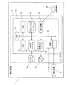
図8は、本発明の検出装置の一実施形態(検出装置1)の構成を示す概略図である。
3-1. Configuration of the device FIG. 8 is a schematic view showing the configuration of one embodiment (detection device 1) of the detection device of the present invention.
図8に示された検出装置1は、反応部、外力付与部、及び撮像部を備える測定装置2を含んでいる。反応部は、前記被検物質に対する結合性を有する捕捉体1が底部に固定化された基板を有し、前記被検物質と前記被検物質に対する結合性を有し且つ標識を含む捕捉体2とを含む反応液を収容する。外力付与部は、前記捕捉体2に対する外力を付与する。撮像部は、基板上の標識由来シグナル配置パターンを撮像する。標識由来シグナル配置パターンを示す画像等の光学的情報は、コンピュータシステム3に送信される。
The
測定装置2としては、例えば、外力付与部及び撮像部を備える顕微鏡を用いることができる。この場合、顕微鏡のステージに設置するウェルプレートの各ウェル、シャーレ等が反応部となる。
As the
顕微鏡としては、標識由来シグナルの1つ1つを認識できる程度の分解能を有する限り特に制限されず、標識の種類及び該標識由来シグナルの検出方法に応じて、適切な顕微鏡を採用することができる。顕微鏡の具体例としては、実体顕微鏡、蛍光顕微鏡、レータ−走査顕微鏡、共焦点レーザー顕微鏡等の光学顕微鏡; 透過型電子顕微鏡、走査型電子顕微鏡等の電子顕微鏡; 原子力間顕微鏡、走査型トンネル顕微鏡、走査型近接場光顕微鏡等の走査型プローブ顕微鏡; X線顕微鏡; 超音波顕微鏡; 等が挙げられる。 The microscope is not particularly limited as long as it has a resolution capable of recognizing each of the labeled signals, and an appropriate microscope can be adopted depending on the type of the label and the method for detecting the labeled signal. .. Specific examples of the microscope include an optical microscope such as a stereoscopic microscope, a fluorescence microscope, a lator-scanning microscope, and a confocal laser microscope; an electron microscope such as a transmission electron microscope and a scanning electron microscope; an internuclear microscope, a scanning tunnel microscope, and the like. Scanning probe microscopes such as scanning close-field light microscopes; X-ray microscopes; ultrasonic microscopes; and the like.
撮像部は、顕微鏡の観察像を撮像できる箇所、例えば接眼レンズ部、写真直筒、Cマウント等に配置されている。撮像部としては、静止画又は動画を撮像可能なものである限り特に制限されず、例えばデジタルカメラ、アナログカメラ、デジタルビデオカメラ、アナログビデオカメラ等が挙げられる。 The imaging unit is arranged at a place where the observation image of the microscope can be imaged, for example, an eyepiece unit, a photographic straight tube, a C mount, or the like. The imaging unit is not particularly limited as long as it can capture a still image or a moving image, and examples thereof include a digital camera, an analog camera, a digital video camera, and an analog video camera.
外力付与部は、外力により捕捉体2を基板上から解離できる部位に配置される。その態様は、外力の調整方法によって、適切な態様を適宜選択することができる。例えば、磁石と基板とが近づくことにより外力が調整される場合であれば、基板上側に、必要に応じて稼働可能な(例えば、垂直方向及び/又は水平方向に稼働可能な)磁石が配置される。別の例として、基板上側に固定された磁石の磁力が調整されることにより外力が調整される場合であれば、基板上側に、電流により磁力を調整可能な磁石が配置される。別の例として、電極の電位が調整されることにより外力が調整される場合であれば、基板上側及び下側に、電流により電位を調整可能な電極が、補足体2を含む液に接触可能な状態で配置される。
The external force applying portion is arranged at a portion where the trapping
図8に示された検出装置1は、測定装置2と直接又はネットワークを介して接続された、処理部を備えるコンピュータシステム3を含んでいる。
The
処理部は、
前記被検物質と、前記捕捉体1と、前記捕捉体2とを液中で接触させ、少なくとも一部の前記捕捉体2を基板上に配置する第1接触工程を実行するよう前記外力付与部からの外力を調整し、前記第1接触工程の後、前記捕捉体2を含む物質の一部を、基板上から解離して液中に遊離させる第1解離工程を実行するよう前記外力付与部からの外力を調整し、前記第1解離工程の後、前記被検物質と、前記被検物質に対する結合性を有し且つ基板に固定されている捕捉体1と、前記被検物質に対する結合性を有し且つ標識を含む捕捉体2とを液中で接触させ、少なくとも一部の前記捕捉体2を基板上に配置する第2接触工程を実行するよう前記外力付与部からの外力を調整し、前記第2接触工程の後、前記捕捉体2を含む物質の一部を、基板上から解離して液中に遊離させる第2解離工程を実行するよう前記外力付与部からの外力を調整し、且つ
前記第1解離工程における解離後の基板上の標識由来シグナル配置パターンと前記第2解離工程における解離後の基板上の標識由来シグナル配置パターンとを比較し、実質的に同位置のシグナルを、被検物質を示すシグナルとして判定する、或いは
前記被検物質と、前記捕捉体1と、前記捕捉体2とを液中で接触させ、少なくとも一部の前記捕捉体2を基板上に配置する第1接触工程を実行するよう前記外力付与部からの外力を調整し、前記第1接触工程の後、前記捕捉体2を含む物質の一部を、基板上から解離して液中に遊離させる第1解離工程を実行するよう前記外力付与部からの外力を調整し、前記第1解離工程の後、前記被検物質と、前記被検物質に対する結合性を有し且つ基板に固定されている捕捉体1と、前記被検物質に対する結合性を有し且つ標識を含む捕捉体2とを液中で接触させ、少なくとも一部の前記捕捉体2を基板上に配置する第2接触工程を実行するよう前記外力付与部からの外力を調整し、且つ
前記第1接触工程における接触後の基板上の標識由来シグナル配置パターンと前記第2接触工程における接触後の基板上の標識由来シグナル配置パターンとを比較し、実質的に同位置のシグナルを、被検物質を示すシグナルとして判定する。
The processing unit
The external force applying unit so as to execute the first contact step of bringing the test substance, the trapping
Comparing the indicator derived signals arranged the pattern on the substrate after dissociation in labeling derived signal arrangement pattern and the second dissociation step on a substrate after dissociation in the first dissociation step, the signals of the actual qualitatively the same position, Judgment as a signal indicating the test substance , or
The external force applying unit so as to execute the first contact step of bringing the test substance, the trapping
The label-derived signal arrangement pattern on the substrate after contact in the first contact step is compared with the label-derived signal arrangement pattern on the substrate after contact in the second contact step, and signals at substantially the same position are applied. Judgment is made as a signal indicating a test substance .
コンピュータシステム3は、コンピュータ本体3aと、入力デバイス3bと、検体情報、結果などを表示する表示部3cとを含む。コンピュータシステム3は、測定装置2から、標識由来シグナル配置パターンが示されている画像等の光学的情報を受信する。そして、コンピュータシステム3のプロセッサは、前記光学的情報に基づいて、被検物質を示すシグナルを判定するプログラムを実行する。
The
図9は、図8に示された検出装置のハードウェア構成を示すブロック図である。 FIG. 9 is a block diagram showing a hardware configuration of the detection device shown in FIG.
図9に示されるように、コンピュータ本体3aは、処理部(CPU(Central Processing Unit))30と、ROM(Read Only Memory)31と、RAM(Random Access Memory)32と、ハードディスク33と、入出力インターフェイス34と、読出装置35と、通信インターフェイス36と、画像出力インターフェイス37とを備えている。処理部(CPU)30、ROM31、RAM32、ハードディスク33、入出力インターフェイス34、読出装置35、通信インターフェイス36及び画像出力インターフェイス37は、バス38によってデータ通信可能に接続されている。
As shown in FIG. 9, the computer
処理部(CPU)30は、ROM31に記憶されているコンピュータプログラム及びRAM32にロードされたコンピュータプログラムを実行することが可能である。処理部(CPU)30がアプリケーションプログラムを実行することにより、被検物質を示すシグナルの判定装置としての端末として機能する。
The processing unit (CPU) 30 can execute the computer program stored in the
ROM31は、マスクROM、PROM、EPROM、EEPROMなどによって構成されている。ROM31には、処理部(CPU)30によって実行されるコンピュータプログラム及びこれに用いるデータが記録されている。
ROM31 is composed of mask ROM, PROM, EPROM, EEPROM and the like. The
RAM32は、SRAM、DRAMなどによって構成されている。RAM32は、ROM31及びハードディスク33に記録されているコンピュータプログラムの読み出しに用いられる。RAM32はまた、これらのコンピュータプログラムを実行するときに、処理部(CPU)30の作業領域として利用される。 RAM32 is composed of SRAM, DRAM, and the like. RAM32 is used to read computer programs recorded on ROM31 and hard disk 33. RAM32 is also used as a work area for the processing unit (CPU) 30 when executing these computer programs.
ハードディスク33は、処理部(CPU)30に実行させるためのオペレーティングシステム、アプリケーションプログラム(被検物質を示すシグナルの判定のためのコンピュータプログラム)などのコンピュータプログラム及び当該コンピュータプログラムの実行に用いるデータがインストールされている。 The hard disk 33 is installed with a computer program such as an operating system for the processing unit (CPU) 30 to execute, an application program (a computer program for determining a signal indicating a test substance), and data used for executing the computer program. Has been done.
読出装置35は、フレキシブルディスクドライブ、CD−ROMドライブ、DVD−ROMドライブなどによって構成されている。読出装置35は、可搬型記録媒体40に記録されたコンピュータプログラム又はデータを読み出すことができる。
The
入出力インターフェイス34は、例えば、USB、IEEE1394、RS−232Cなどのシリアルインターフェイスと、SCSI、IDE、IEEE1284などのパラレルインターフェイスと、D/A変換器、A/D変換器などからなるアナログインターフェイスとから構成されている。入出力インターフェイス34には、キーボード、マウスなどの入力デバイス3bが接続されている。操作者は、当該入力デバイス3bを使用することにより、コンピュータ本体3aにデータを入力することが可能である。
The input /
通信インターフェイス36は、例えば、Ethernet(登録商標)インターフェイスなどである。コンピュータシステム3は、通信インターフェイス36により、プリンタへの印刷データの送信が可能である。
The
画像出力インターフェイス37は、LCD、CRTなどで構成される表示部3cに接続されている。これにより、表示部3cは、処理部(CPU)30から与えられた画像データに応じた映像信号を出力することができる。表示部3cは、入力された映像信号にしたがって画像(画面)を表示する。
The image output interface 37 is connected to a
3-2.装置の動作
次に図10を用いて、本発明の検出装置の動作を説明する。本発明の検出装置の動作は、コンピュータシステム3の処理部(CPU)30が制御する。
3-2. Operation of the device Next, the operation of the detection device of the present invention will be described with reference to FIG. The operation of the detection device of the present invention is controlled by the processing unit (CPU) 30 of the
初めに、処理部30は、前記被検物質と、前記捕捉体1と、前記捕捉体2とを液中で接触させ、少なくとも一部の前記捕捉体2を基板上に配置するよう前記外力付与部からの外力を調整し、前記接触の後、前記捕捉体2を含む物質の一部を、基板上から解離して液中に遊離させるよう前記外力付与部からの外力を調整する。この接触及び解離からなるセットは、必要に応じて複数回行われる。
First, the
次に、処理部30は、検査者が入力デバイス3bから行う、コンピュータ本体3aに対する、測定装置2によって生成された標識由来シグナル配置パターンを示す画像等の光学的情報の取得を開始するための入力を受け付ける(ステップS0)。
Next, the
続いて、処理部30は、測定装置2によって生成された標識由来シグナル配置パターンを示す画像等の光学的情報を取得する(ステップS1)。この際、2種の標識由来シグナル配置パターン、具体的には、第1解離工程の配置パターン及び第2解離工程の配置パターン、又は第1接触工程及び第2接触工程の配置パターンが取得されるが、これらは同時に取得されてもよいし、別々に取得されてもよい。
Subsequently, the
続いて、処理部30は、ステップS1で取得された2種の標識由来シグナル配置パターンを比較する(ステップS2)。具体的には、2種の標識由来シグナル配置パターン間で、それぞれのシグナルの位置を比較する。比較した結果、2種の標識由来シグナル配置パターンで、実質的に同位置のシグナルは、被検物質を示すシグナルとして判定し(ステップS3)、実質的に同位置ではないシグナルは、被検物質を示さないシグナルとして判定する(ステップS4)。
Subsequently, the
この比較及び判定のより具体的な態様は、例えば次のとおりである。一方の標識由来シグナル配置パターンを示す画像(画像1)と、他方の標識由来シグナル配置パターンを示す画像1と同一視野の画像(画像2)とを、座標系に基づいて複数の区画に分割し、画像1のあるシグナルと画像2のあるシグナルが同じ区画内に存在するか否かを比較する。その結果、両者のシグナルが同じ区画内に存在すれば、両者は実質的に同位置のシグナルであると判定することができる。
More specific aspects of this comparison and determination are, for example: The image showing the signal arrangement pattern derived from one label (image 1) and the image having the same field of view as the
この比較及び判定のより具体的な態様の別の例は、次のとおりである。一方の標識由来シグナル配置パターンを示す画像(画像A)において、シグナルの輝度分布に基づいて輝度重心を決定する。そして、他方の標識由来シグナル配置パターンを示す画像1と同一視野の画像(画像B)におけるシグナルが、画像A中のシグナルの該輝度重心から所定範囲内に存在するか否かを比較する。その結果、画像Bにおけるシグナルが、画像A中のシグナルの該輝度重心から所定範囲内に存在すれば、両者は実質的に同位置のシグナルであると判定することができる。
Another example of a more specific aspect of this comparison and determination is: In the image (image A) showing the signal arrangement pattern derived from one of the markers, the luminance center of gravity is determined based on the luminance distribution of the signal. Then, it is compared whether or not the signal in the image (image B) having the same field of view as the
この比較及び判定のより具体的な態様の別の例は、次のとおりである。この例は、被検物質、捕捉体1、及び捕捉体2の複合体が1つ入る程度のサイズのウェルを複数有するウェルプレートを用いる場合の例である。この例においては、標識由来シグナルが検出されるウェル(陽性ウェル)が標識由来シグナルそのものであるといえる。このため、一方の標識由来シグナル配置パターンにおける陽性ウェル(シグナルが観察されたウェル)のプレート上の位置と、一方の標識由来シグナル配置パターンにおける陽性ウェル(シグナルが観察されたウェル)のプレート上の位置とを比較し、その結果、両者がプレート上の同じ位置であれば、両者は同位置のシグナルであると判定することができる。
Another example of a more specific aspect of this comparison and determination is: This example is an example in which a well plate having a plurality of wells sized to accommodate one complex of the test substance, the trapping
被検物質を示すと判定されたシグナルは、被検物質として検出する(ステップS5)。 The signal determined to indicate the test substance is detected as the test substance (step S5).
処理部30は、ステップS1〜S5の情報を、画像出力インターフェイス37を介して、表示部3cから出力することができる。また、処理部30は、これらの情報を、記録媒体40等に記録してもよい。
The
ステップS1〜S5はコンピュータプログラムによって実行される。コンピュータプログラムは、ハードディスク、フラッシュメモリ等の半導体メモリ素子、光ディスク等の記憶媒体に記憶されていてもよい。前記記憶媒体へのプログラムの記憶形式は、前記提示装置が前記プログラムを読み取り可能である限り制限されない。前記記憶媒体への記憶は、不揮発性であることが好ましい。 Steps S1 through S5 are performed by a computer program. The computer program may be stored in a semiconductor memory element such as a hard disk or a flash memory, or a storage medium such as an optical disk. The storage format of the program in the storage medium is not limited as long as the presenting device can read the program. The storage in the storage medium is preferably non-volatile.
3-3.被検物質を検出する装置のその他の態様
本発明は、その一態様において、反応部と、外力付与部と、撮像部と、制御部と、処理部と、を備える装置にも関する。
3-3. Other Aspects of a Device for Detecting a Test Substance The present invention also relates to a device including a reaction unit, an external force applying unit, an imaging unit, a control unit, and a processing unit in one aspect thereof.
本態様において、制御部は、
前記被検物質と、前記捕捉体1と、前記捕捉体2とを液中で接触させ、少なくとも一部の前記捕捉体2を基板上に配置する第1接触工程を実行するよう前記外力付与部からの外力を調整し、前記第1接触工程の後、前記捕捉体2を含む物質の一部を、基板上から解離して液中に遊離させる第1解離工程を実行するよう前記外力付与部からの外力を調整し、前記第1解離工程の後、前記被検物質と、前記被検物質に対する結合性を有し且つ基板に固定されている捕捉体1と、前記被検物質に対する結合性を有し且つ標識を含む捕捉体2とを液中で接触させ、少なくとも一部の前記捕捉体2を基板上に配置する第2接触工程を実行するよう前記外力付与部からの外力を調整し、前記第2接触工程の後、前記捕捉体2を含む物質の一部を、基板上から解離して液中に遊離させる第2解離工程を実行するよう前記外力付与部からの外力を調整する、或いは
前記被検物質と、前記捕捉体1と、前記捕捉体2とを液中で接触させ、少なくとも一部の前記捕捉体2を基板上に配置する第1接触工程を実行するよう前記外力付与部からの外力を調整し、前記第1接触工程の後、前記捕捉体2を含む物質の一部を、基板上から解離して液中に遊離させる第1解離工程を実行するよう前記外力付与部からの外力を調整し、前記第1解離工程の後、前記被検物質と、前記被検物質に対する結合性を有し且つ基板に固定されている捕捉体1と、前記被検物質に対する結合性を有し且つ標識を含む捕捉体2とを液中で接触させ、少なくとも一部の前記捕捉体2を基板上に配置する第2接触工程を実行するよう前記外力付与部からの外力を調整する。制御部は、測定装置2内に備えられるものであり、その構成はコンピュータシステム3と同様の構成を採ることができる。
In this embodiment, the control unit is
The external force applying unit so as to execute the first contact step of bringing the test substance, the trapping
The external force applying unit so as to execute the first contact step of bringing the test substance, the trapping
本態様において、処理部は、
前記第1解離工程における解離後の基板上の標識由来シグナル配置パターンと前記第2解離工程における解離後の基板上の標識由来シグナル配置パターンとを比較し、実質的に同位置のシグナルを、被検物質を示すシグナルとして判定する、或いは
前記第1接触工程における接触後の基板上の標識由来シグナル配置パターンと前記第2接触工程における接触後の基板上の標識由来シグナル配置パターンとを比較し、実質的に同位置のシグナルを、被検物質を示すシグナルとして判定する。処理部の構成については、上記3-1における説明が援用される。
In this embodiment, the processing unit is
Comparing the indicator derived signals arranged the pattern on the substrate after dissociation in labeling derived signal arrangement pattern and the second dissociation step on a substrate after dissociation in the first dissociation step, the signals of the actual qualitatively the same position, Judgment as a signal indicating the test substance, or
The label-derived signal arrangement pattern on the substrate after contact in the first contact step is compared with the label-derived signal arrangement pattern on the substrate after contact in the second contact step, and signals at substantially the same position are applied. Judgment is made as a signal indicating a test substance . The configuration of the processing unit, described in the above 3-1 can be incorporated.
以下に、実施例に基づいて本発明を詳細に説明するが、本発明はこれらの実施例によって限定されるものではない。 Hereinafter, the present invention will be described in detail based on examples, but the present invention is not limited to these examples.
実施例1.ApoA1の検出
1-1.接触工程1
1-1-1.捕捉体1の調製
シリコンゴムシート(タイガースポリマー社製、SR-50、厚み5 mm)に直径5 mmの貫通孔を開け、得られたシートをMASコートガラス(松浪硝子工業株式会社製)に貼り付けて、ガラス基板上にウェルを作製した。BSA(Proliant biologicals社製、#68700)に定法に従ってビオチンを結合させ、ビオチン結合BSAを得た。30μg/mLビオチン結合BSA/PBS溶液 0.5μLをウェルに滴下して、室温で1時間静置した。HISCL洗浄液(シスメックス社製) 50μLをウェルに滴下後、ピペッティングによりウェルを洗浄した。この洗浄操作を計3回行った(以下、この3回の洗浄を、単に「洗浄操作」と示す。)。1%BSA/PBS溶液 50μLをウェルに滴下し、4℃で一晩静置した後、洗浄操作を行った。10μg/mLストレプトアビジン/1%BSA/PBST溶液 20μLをウェルに滴下し、室温で1時間静置した後、洗浄操作を行った。一方で、ビオチン標識したAnti ApoA1 Antibody P1A5(Sysmex社製)をStartingBloc(登録商標) (PBS) Blocking Buffer(Thermo Fisher Scientific社製)で10μg/mLに希釈して、被検物質に対する抗体溶液を作製した。該抗体溶液 10μLをウェルに添加し、室温で1時間静置した後、洗浄操作を行った。上記操作により、被検物質(ApoA1)に対する結合性を有し且つ基板(ウェル底面)に固定されている捕捉体1を得た。
Example 1. ApoA1 detection
1-1.
1-1-1. Preparation of
1-1-2.被検物質の基板上への配置
ApoA1, human recombinant(Sigma Aldrich製)をStartingBloc(登録商標) (PBS) Blocking Buffer(Thermo Fisher Scientific製)で1μg/mLに希釈して、サンプル溶液を作製した。一方で、ApoA1を含まないBlocking Bufferのみの液を準備し、これをバックグラウンド溶液とした。実施例1-1-1で得られたウェルに、サンプル溶液 20μL又はバックグラウンド溶液 20μLを添加し、室温で1時間静置した。上記操作により、被検物質を基板上に配置した。
1-1-2. Placement of test substance on substrate
ApoA1, human recombinant (manufactured by Sigma Aldrich) was diluted to 1 μg / mL with Starting Bloc (registered trademark) (PBS) Blocking Buffer (manufactured by Thermo Fisher Scientific) to prepare a sample solution. On the other hand, a solution containing only Blocking Buffer containing no ApoA1 was prepared, and this was used as a background solution. To the wells obtained in Example 1-1-1, 20 μL of the sample solution or 20 μL of the background solution was added, and the mixture was allowed to stand at room temperature for 1 hour. By the above operation, the test substance was placed on the substrate.
1-1-3.捕捉体2の調製
Anti ApoA1 Antibody P1A5(Sysmex製)と磁性ビーズ(多摩川精機製、COOH FG beads、TAS8848N1140、直径180 nm)を、N-ヒドロキシスクシイミド(キシダ化学株式会社、010-38472)及び1-エチル-3-(3-ジメチルアミノプロピル)カルボジイミド塩酸塩(同仁化学研究所、W001)と混合し、抗体にビーズを結合した。この操作により、被検物質(ApoA1)に対する結合性を有し且つ標識(ビーズ)を含む捕捉体2を得た。
1-1-3. Preparation of
Anti ApoA1 Antibody P1A5 (manufactured by Sysmex) and magnetic beads (manufactured by Tamagawa Seiki, COOH FG beads, TAS8848N1140, diameter 180 nm), N-hydroxysucciimide (Kishida Chemical Co., Ltd., 010-38472) and 1-ethyl-3. -(3-Dimethylaminopropyl) carbodiimide hydrochloride (Dojin Chemical Laboratory, W001) was mixed and beads were bound to the antibody. By this operation, a
1-1-4.捕捉体2の基板上への配置
実施例1-1-2の操作後のウェルに、捕捉体2溶液 40μLを添加し、室温で1時間静置した。この操作により、捕捉体2を基板上に配置した。操作終了後に、顕微鏡(BZX710、KEYENCE製)のステージ上に、ウェルを含む基板を設置し、焦点をウェル底面付近に設定し、×40, NA=0.95のレンズを用いて明視野像(接触工程1の明視野像)を取得した。
1-1-4. Placement of
1-2.解離工程1
実施例1-1-4の操作後のウェルを、カバーガラス(松浪硝子株式会社製)で封止した。磁石(株式会社二六製作所製、N40、表面磁束密度400mT)をウェル底面から5mmの高さまで近づけることにより、捕捉体2(中の磁性ビーズ)を上方に引っ張る外力を、30秒間付与した。この操作により、捕捉体2を含む物質を基板上から解離して液中に遊離させた。なお、この間、磁石は、水平方向に僅かに揺らし続けた。外力付与直後に、実施例1-1-4と同様にして明視野像(解離工程1の明視野像)を取得した。
1-2.
The wells after the operation of Example 1-1-4 were sealed with a cover glass (manufactured by Matsunami Glass Co., Ltd.). By bringing a magnet (manufactured by 26 Seisakusho Co., Ltd., N40, surface magnetic flux density 400 mT) close to a height of 5 mm from the bottom of the well, an external force that pulls the trap 2 (magnetic beads inside) upward was applied for 30 seconds. By this operation, the substance containing the
1-3.接触工程2及び解離工程2
実施例1-2の操作後、ウェルに磁力が完全に及ばない位置まで磁石を離し、その状態で5分間静置した。この操作により、再度、捕捉体2を基板上に配置した。静置後に、実施例1-1-4と同様にして明視野像(接触工程2の明視野像)を取得した。
1-3. Contact
After the operation of Example 1-2, the magnet was separated to a position where the magnetic force did not completely reach the well, and the magnet was allowed to stand in that state for 5 minutes. By this operation, the
その後、実施例1-2と同様にして、外力を付与し、その直後に明視野像(解離工程2の明視野像)を取得した。 Then, an external force was applied in the same manner as in Example 1-2, and immediately after that, a bright-field image (bright-field image of dissociation step 2) was obtained.
1-4.接触工程3及び解離工程3
実施例1-3の操作後、実施例1-3と同様にして、接触工程3及び解離工程3を行い、それぞれの明視野像(接触工程3の明視野像及び解離工程3の明視野像)を取得した。
1-4. Contact
After the operation of Example 1-3, the
1-5.接触工程4及び解離工程4
実施例1-4の操作後、実施例1-3と同様にして、接触工程4及び解離工程4を行い、それぞれの明視野像(接触工程4の明視野像及び解離工程4の明視野像)を取得した。
1-5. Contact
After the operation of Example 1-4, the
1-6.基板上の標識由来シグナル配置パターンの比較1(解離工程同士の比較)
上記実施例で取得された明視野像は、標識(磁性ビーズ)が拡大され輝点シグナルとして判別可能な像である。明視野像の一部を図11に示す。図11中、矢印は輝点を示し、グレー矢印はいずれの解離工程同士を比較しても位置が不変の輝点を示し、白色矢印は異なる解離工程間で位置が変化している輝点を示す。また、複数の視野における輝点の数を積算した結果を、図12に示す。
1-6. Comparison of label-derived signal arrangement patterns on the substrate 1 (Comparison between dissociation steps)
The bright-field image obtained in the above embodiment is an image in which the label (magnetic beads) is enlarged and can be discriminated as a bright spot signal. A part of the bright field image is shown in FIG. In FIG. 11, arrows indicate bright spots, gray arrows indicate bright spots whose positions do not change regardless of which dissection process is compared, and white arrows indicate bright spots whose positions change between different dissection steps. show. Further, FIG. 12 shows the result of integrating the number of bright spots in a plurality of fields of view.
図11に示されるように、解離工程1〜4のいずれの解離工程間でも位置が不変の輝点が存在することが分かった。これらの輝点は、外力を加えた後でも基板上に固定されている捕捉体2に由来するシグナルであり、被検物質をより特異的に示すシグナルであることが示唆された。また、このことから、接触工程間で位置が不変の輝点も、外力を加えた後でも基板上に固定されている捕捉体2に由来するシグナルであるといえ、被検物質をより特異的に示すシグナルとして判定できることが示唆された。
As shown in FIG. 11, it was found that there were bright spots whose positions did not change between the dissection steps 1 to 4. It was suggested that these bright spots are signals derived from the
図12に示されるように、バックグラウンド溶液を使用した場合(被検物質 無の場合)の輝点、すなわち非特異的吸着に基づくシグナルは、解離工程により減少することが分かった。特に、解離工程を2回行った後(解離工程2〜4)では、非特異的シグナルは0であった。
As shown in FIG. 12, it was found that the bright spots when the background solution was used (without the test substance), that is, the signal based on non-specific adsorption, was reduced by the dissociation step. In particular, after performing the dissociation step twice (
比較例1.従来法によるApoA1の検出
従来から通常に実施されている、B/F分離によるELISA法に準じて、被検物質(ApoA1)を検出した。具体的には次のようにして行った。実施例1-1と同様にして捕捉体2を基板上へ配置した。続いて、上清を除去して、PBS 20μLを添加した。その後、焦点をウェル底面付近とした明視野像を取得した。
Comparative example 1. Detection of ApoA1 by the conventional method The test substance (ApoA1) was detected according to the ELISA method by B / F separation, which has been usually performed conventionally. Specifically, it was carried out as follows. The
明視野像を図13に示す。また、複数の視野における輝点の数を積算した結果を、図14に示す。 A bright field image is shown in FIG. Further, FIG. 14 shows the result of integrating the number of bright spots in a plurality of fields of view.
図13に示されるように、B/F分離による従来法では、バックグラウンド溶液を使用した場合(被検物質無の場合)でも、輝点、すなわち非特異的吸着に基づくシグナルがある程度残ってしまう。 As shown in FIG. 13, in the conventional method by B / F separation, even when a background solution is used (without a test substance), a bright spot, that is, a signal based on non-specific adsorption remains to some extent. ..
1. 検出装置
2. 測定装置
3. コンピュータシステム
3a.コンピュータ本体
3b.入力デバイス
3c.表示部
30.処理部(CPU)
1. 1.
Claims (20)
前記被検物質と、前記被検物質に対する結合性を有し且つ基板に固定されている捕捉体1と、前記被検物質に対する結合性を有し且つ標識を含む捕捉体2とを液中で接触させ、少なくとも一部の前記捕捉体2を基板上に配置する第1接触工程、
前記第1接触工程の後、前記捕捉体2を含む物質の一部を、基板上から解離して液中に遊離させる第1解離工程、
前記第1解離工程の後、前記被検物質と、前記被検物質に対する結合性を有し且つ基板に固定されている捕捉体1と、前記被検物質に対する結合性を有し且つ標識を含む捕捉体2とを液中で接触させ、少なくとも一部の前記捕捉体2を基板上に配置する第2接触工程、
前記第2接触工程の後、前記捕捉体2を含む物質の一部を、基板上から解離して液中に遊離させる第2解離工程、及び
前記第1解離工程における解離後の基板上の標識由来シグナル配置パターンと前記第2解離工程における解離後の基板上の標識由来シグナル配置パターンとを比較し、実質的に同位置のシグナルを、被検物質を示すシグナルとして検出する検出工程、
を含む方法。 It is a method to detect the test substance,
The test substance, a trap 1 having a binding property to the test substance and fixed to a substrate, and a trap 2 having a binding property to the test substance and containing a label are placed in a liquid. The first contact step of contacting and arranging at least a part of the trap 2 on the substrate,
After the first contact step, the first dissociation step of dissociating a part of the substance containing the trap 2 from the substrate and releasing it into the liquid.
After the first dissociation step, the test substance, the trap 1 which has the bondability to the test substance and is fixed to the substrate, and the catcher 1 which has the bondability to the test substance and contains a label. A second contact step of bringing the trap 2 into contact with the liquid and arranging at least a part of the trap 2 on the substrate.
After the second contact step, a second dissociation step of dissociating a part of the substance containing the trap 2 from the substrate and releasing it into the liquid, and a labeling on the substrate after dissociation in the first dissociation step. A detection step of comparing the derived signal arrangement pattern with the label-derived signal arrangement pattern on the substrate after dissociation in the second dissociation step, and detecting a signal at substantially the same position as a signal indicating a test substance.
How to include.
前記被検物質と、前記被検物質に対する結合性を有し且つ基板に固定されている捕捉体1と、前記被検物質に対する結合性を有し且つ標識を含む捕捉体2とを液中で接触させ、少なくとも一部の前記捕捉体2を基板上に配置する第1接触工程、
前記第1接触工程の後、前記捕捉体2を含む物質の一部を、基板上から解離して液中に遊離させる第1解離工程、
前記第1解離工程の後、前記被検物質と、前記被検物質に対する結合性を有し且つ基板に固定されている捕捉体1と、前記被検物質に対する結合性を有し且つ標識を含む捕捉体2とを液中で接触させ、少なくとも一部の前記捕捉体2を基板上に配置する第2接触工程、及び
前記第1接触工程における接触後の基板上の標識由来シグナル配置パターンと前記第2接触工程における接触後の基板上の標識由来シグナル配置パターンとを比較し、実質的に同位置のシグナルを、被検物質を示すシグナルとして検出する検出工程、
を含む方法。 It is a method to detect the test substance,
The test substance, a trap 1 having a binding property to the test substance and fixed to a substrate, and a trap 2 having a binding property to the test substance and containing a label are placed in a liquid. The first contact step of contacting and arranging at least a part of the trap 2 on the substrate,
After the first contact step, the first dissociation step of dissociating a part of the substance containing the trap 2 from the substrate and releasing it into the liquid.
After the first dissociation step, the test substance, the trap 1 which has the bondability to the test substance and is fixed to the substrate, and the catcher 1 which has the bondability to the test substance and contains a label. A second contact step of bringing the trap 2 into contact with the liquid and arranging at least a part of the trap 2 on the substrate, and a label-derived signal arrangement pattern on the substrate after contact in the first contact step and the above. A detection step in which a signal at substantially the same position is detected as a signal indicating a test substance by comparing with a label-derived signal arrangement pattern on the substrate after contact in the second contact step.
How to include.
前記第2解離工程において捕捉体2を基板から解離した後に、基板上の前記標識由来シグナル配置パターンを示す画像Qを撮影し、且つ
前記検出工程において、前記画像P内の前記標識由来シグナルの位置と前記画像Q内の前記標識由来シグナルの位置とを比較して、前記画像Q内の前記標識由来シグナルの内、前記画像P内の前記標識由来シグナルと実質的に同位置の前記標識由来シグナルを、被検物質を示すシグナルとして検出する、
請求項1に記載の方法。 After dissociating the trap 2 from the substrate in the first dissociation step, an image P showing the label-derived signal arrangement pattern on the substrate was taken.
After dissociating the trap 2 from the substrate in the second dissociation step, an image Q showing the label-derived signal arrangement pattern on the substrate is taken, and in the detection step, the position of the label-derived signal in the image P is taken. And the position of the label-derived signal in the image Q, among the label-derived signals in the image Q, the label-derived signal at substantially the same position as the label-derived signal in the image P. Is detected as a signal indicating the test substance,
The method according to claim 1.
前記検出工程において、前記動画内で、前記第1解離工程から前記第2解離工程まで実質的に同位置であり続ける前記標識由来シグナルを、被検物質を示すシグナルとして検出する、
請求項1に記載の方法。 A moving image showing the label-derived signal arrangement pattern on the substrate in the first dissociation step and the second dissociation step was taken.
In the detection step, the label-derived signal that remains substantially at the same position from the first dissociation step to the second dissociation step in the moving image is detected as a signal indicating the test substance.
The method according to claim 1.
前記第2接触工程において捕捉体2を基板上に配置した後に、基板上の前記標識由来シグナル配置パターンを示す画像Yを撮影し、且つ
前記検出工程において、前記画像X内の前記標識由来シグナルの位置と前記画像Y内の前記標識由来シグナルの位置とを比較して、前記画像Y内の前記標識由来シグナルの内、前記画像X内の前記標識由来シグナルと実質的に同位置のシグナルを、被検物質を示すシグナルとして検出する、
請求項2に記載の方法。 After arranging the capture body 2 on the substrate in the first contact step, an image X showing the label-derived signal arrangement pattern on the substrate was taken.
After arranging the capture body 2 on the substrate in the second contact step, an image Y showing the label-derived signal arrangement pattern on the substrate is taken, and in the detection step, the label-derived signal in the image X is captured. By comparing the position with the position of the label-derived signal in the image Y, a signal having substantially the same position as the label-derived signal in the image X among the label-derived signals in the image Y is displayed. Detected as a signal indicating the test substance,
The method according to claim 2.
前記検出工程において、前記動画内で、前記第1接触工程から前記第2接触工程まで実質的に同位置であり続ける前記標識由来シグナルを、被検物質を示すシグナルとして検出する、
請求項2に記載の方法。 A moving image showing the sign-derived signal arrangement pattern on the substrate in the first contact step and the second contact step was taken.
In the detection step, the label-derived signal that remains substantially at the same position from the first contact step to the second contact step in the moving image is detected as a signal indicating the test substance.
The method according to claim 2.
反応液を収容する反応部と、前記反応液は、前記被検物質と前記被検物質に対する結合性を有し且つ標識を含む捕捉体2とを含み、前記反応部の底部は前記被検物質に対する結合性を有する捕捉体1が固定化された基板であり、
前記捕捉体2に対する外力を付与する外力付与部と、
基板上の標識由来シグナル配置パターンを撮像する撮像部と、
前記被検物質と、前記捕捉体1と、前記捕捉体2とを液中で接触させ、少なくとも一部の前記捕捉体2を基板上に配置する第1接触工程を実行するよう前記外力付与部からの外力を調整し、前記第1接触工程の後、前記捕捉体2を含む物質の一部を、基板上から解離して液中に遊離させる第1解離工程を実行するよう前記外力付与部からの外力を調整し、前記第1解離工程の後、前記被検物質と、前記被検物質に対する結合性を有し且つ基板に固定されている捕捉体1と、前記被検物質に対する結合性を有し且つ標識を含む捕捉体2とを液中で接触させ、少なくとも一部の前記捕捉体2を基板上に配置する第2接触工程を実行するよう前記外力付与部からの外力を調整し、前記第2接触工程の後、前記捕捉体2を含む物質の一部を、基板上から解離して液中に遊離させる第2解離工程を実行するよう前記外力付与部からの外力を調整し、且つ
前記第1解離工程における解離後の基板上の標識由来シグナル配置パターンと前記第2解離工程における解離後の基板上の標識由来シグナル配置パターンとを比較し、実質的に同位置のシグナルを、被検物質を示すシグナルとして判定する
処理部と、
を備える装置。 A device that detects a test substance
The reaction section containing the reaction solution and the reaction solution include the test substance and a trap 2 having a binding property to the test substance and containing a label, and the bottom of the reaction section is the test substance. It is a substrate on which the trapping body 1 having a binding property to is immobilized.
An external force applying portion that applies an external force to the trapping body 2 and an external force applying portion.
An imaging unit that captures the signal arrangement pattern derived from the label on the substrate,
The external force applying unit so as to execute the first contact step of bringing the test substance, the trapping body 1 and the trapping body 2 into contact with each other in a liquid and arranging at least a part of the trapping body 2 on the substrate. After the first contact step , the external force applying unit so as to execute the first dissociation step of dissociating a part of the substance containing the trap 2 from the substrate and releasing it into the liquid. After the first dissociation step, the external force from the test substance is adjusted, and after the first dissociation step, the test substance, the trapping body 1 having the bondability to the test substance and fixed to the substrate, and the bondability to the test substance The external force from the external force applying portion is adjusted so as to execute the second contact step of contacting the trapping body 2 containing the label and having the captive body 2 in the liquid and arranging at least a part of the trapping body 2 on the substrate. After the second contact step, the external force from the external force applying portion is adjusted so as to execute the second dissociation step of dissociating a part of the substance containing the trap 2 from the substrate and releasing it into the liquid. And
Comparing the indicator derived signals arranged the pattern on the substrate after dissociation in labeling derived signal arrangement pattern and the second dissociation step on a substrate after dissociation in the first dissociation step, the signals of the actual qualitatively the same position, A processing unit that determines as a signal indicating the test substance, and
A device equipped with.
反応液を収容する反応部と、前記反応液は、前記被検物質と前記被検物質に対する結合性を有し且つ標識を含む捕捉体2とを含み、前記反応部の底部は前記被検物質に対する結合性を有する捕捉体1が固定化された基板であり、 The reaction section containing the reaction solution and the reaction solution include the test substance and a trap 2 having a binding property to the test substance and containing a label, and the bottom of the reaction section is the test substance. It is a substrate on which the trapping body 1 having a binding property to is immobilized.
前記捕捉体2に対する外力を付与する外力付与部と、 An external force applying portion that applies an external force to the trapping body 2 and an external force applying portion.
基板上の標識由来シグナル配置パターンを撮像する撮像部と、 An imaging unit that captures the signal arrangement pattern derived from the label on the substrate,
前記被検物質と、前記捕捉体1と、前記捕捉体2とを液中で接触させ、少なくとも一部の前記捕捉体2を基板上に配置する第1接触工程を実行するよう前記外力付与部からの外力を調整し、前記第1接触工程の後、前記捕捉体2を含む物質の一部を、基板上から解離して液中に遊離させる第1解離工程を実行するよう前記外力付与部からの外力を調整し、前記第1解離工程の後、前記被検物質と、前記被検物質に対する結合性を有し且つ基板に固定されている捕捉体1と、前記被検物質に対する結合性を有し且つ標識を含む捕捉体2とを液中で接触させ、少なくとも一部の前記捕捉体2を基板上に配置する第2接触工程を実行するよう前記外力付与部からの外力を調整し、且つ The external force applying unit so as to execute the first contact step of bringing the test substance, the trapping body 1 and the trapping body 2 into contact with each other in a liquid and arranging at least a part of the trapping body 2 on the substrate. After the first contact step, the external force applying unit so as to execute the first dissociation step of dissociating a part of the substance containing the trap 2 from the substrate and releasing it into the liquid. After the first dissociation step, the external force from the test substance is adjusted, and after the first dissociation step, the test substance, the trapping body 1 having the bondability to the test substance and fixed to the substrate, and the bondability to the test substance The external force from the external force applying portion is adjusted so as to execute the second contact step of contacting the trapped body 2 having the above and containing the label in the liquid and arranging at least a part of the trapped body 2 on the substrate. ,and
前記第1接触工程における接触後の基板上の標識由来シグナル配置パターンと前記第2接触工程における接触後の基板上の標識由来シグナル配置パターンとを比較し、実質的に同位置のシグナルを、被検物質を示すシグナルとして判定する The label-derived signal arrangement pattern on the substrate after contact in the first contact step is compared with the label-derived signal arrangement pattern on the substrate after contact in the second contact step, and signals at substantially the same position are applied. Judgment as a signal indicating the substance to be detected
処理部と、 Processing unit and
を備える装置。 A device equipped with.
前記被検物質に対する結合性を有する捕捉体1が底部に固定化された基板を有し、前記被検物質と前記被検物質に対する結合性を有し且つ標識を含む捕捉体2とを含む反応液を収容する反応部と、
前記捕捉体2に対する外力を付与する外力付与部と、
基板上の標識由来シグナル配置パターンを撮像する撮像部と、
前記被検物質と、前記捕捉体1と、前記捕捉体2とを液中で接触させ、少なくとも一部の前記捕捉体2を基板上に配置する第1接触工程を実行するよう前記外力付与部からの外力を調整し、前記第1接触工程の後、前記捕捉体2を含む物質の一部を、基板上から解離して液中に遊離させる第1解離工程を実行するよう前記外力付与部からの外力を調整し、前記第1解離工程の後、前記被検物質と、前記被検物質に対する結合性を有し且つ基板に固定されている捕捉体1と、前記被検物質に対する結合性を有し且つ標識を含む捕捉体2とを液中で接触させ、少なくとも一部の前記捕捉体2を基板上に配置する第2接触工程を実行するよう前記外力付与部からの外力を調整し、前記第2接触工程の後、前記捕捉体2を含む物質の一部を、基板上から解離して液中に遊離させる第2解離工程を実行するよう前記外力付与部からの外力を調整する制御部と、
前記第1解離工程における解離後の基板上の標識由来シグナル配置パターンと前記第2解離工程における解離後の基板上の標識由来シグナル配置パターンとを比較し、実質的に同位置のシグナルを、被検物質を示すシグナルとして判定する処理部と、
を備える装置。 A device that detects a test substance
A reaction in which a trap 1 having a binding property to a test substance has a substrate immobilized on the bottom and contains the test substance and a trap body 2 having a binding property to the test substance and containing a label. The reaction part that houses the liquid and
An external force applying portion that applies an external force to the trapping body 2 and an external force applying portion.
An imaging unit that captures the signal arrangement pattern derived from the label on the substrate,
The external force applying unit so as to execute the first contact step of bringing the test substance, the trapping body 1 and the trapping body 2 into contact with each other in a liquid and arranging at least a part of the trapping body 2 on the substrate. After the first contact step , the external force applying unit so as to execute the first dissociation step of dissociating a part of the substance containing the trap 2 from the substrate and releasing it into the liquid. After the first dissociation step, the external force from the test substance is adjusted, and after the first dissociation step, the test substance, the trapping body 1 having the bondability to the test substance and fixed to the substrate, and the bondability to the test substance The external force from the external force applying portion is adjusted so as to execute the second contact step of contacting the trapping body 2 containing the label and having the captive body 2 in the liquid and arranging at least a part of the trapping body 2 on the substrate. After the second contact step, the external force from the external force applying portion is adjusted so as to execute the second dissociation step of dissociating a part of the substance containing the trap 2 from the substrate and releasing it into the liquid. Control unit and
Comparing the indicator derived signals arranged the pattern on the substrate after dissociation in labeling derived signal arrangement pattern and the second dissociation step on a substrate after dissociation in the first dissociation step, the signals of the actual qualitatively the same position, A processing unit that determines as a signal indicating the test substance, and
A device equipped with.
前記被検物質に対する結合性を有する捕捉体1が底部に固定化された基板を有し、前記被検物質と前記被検物質に対する結合性を有し且つ標識を含む捕捉体2とを含む反応液を収容する反応部と、 A reaction in which a trap 1 having a binding property to a test substance has a substrate immobilized on the bottom and contains the test substance and a trap body 2 having a binding property to the test substance and containing a label. The reaction part that houses the liquid and
前記捕捉体2に対する外力を付与する外力付与部と、 An external force applying portion that applies an external force to the trapping body 2 and an external force applying portion.
基板上の標識由来シグナル配置パターンを撮像する撮像部と、 An imaging unit that captures the signal arrangement pattern derived from the label on the substrate,
前記被検物質と、前記捕捉体1と、前記捕捉体2とを液中で接触させ、少なくとも一部の前記捕捉体2を基板上に配置する第1接触工程を実行するよう前記外力付与部からの外力を調整し、前記第1接触工程の後、前記捕捉体2を含む物質の一部を、基板上から解離して液中に遊離させる第1解離工程を実行するよう前記外力付与部からの外力を調整し、前記第1解離工程の後、前記被検物質と、前記被検物質に対する結合性を有し且つ基板に固定されている捕捉体1と、前記被検物質に対する結合性を有し且つ標識を含む捕捉体2とを液中で接触させ、少なくとも一部の前記捕捉体2を基板上に配置する第2接触工程を実行するよう前記外力付与部からの外力を調整する制御部と、 The external force applying unit so as to execute the first contact step of bringing the test substance, the trapping body 1 and the trapping body 2 into contact with each other in a liquid and arranging at least a part of the trapping body 2 on the substrate. After the first contact step, the external force applying unit so as to execute the first dissociation step of dissociating a part of the substance containing the trap 2 from the substrate and releasing it into the liquid. After the first dissociation step, the external force from the test substance is adjusted, and after the first dissociation step, the test substance, the trapping body 1 having the bondability to the test substance and fixed to the substrate, and the bondability to the test substance The external force from the external force applying portion is adjusted so as to execute the second contact step of arranging at least a part of the trapped body 2 on the substrate by bringing the trapped body 2 having the mark and containing the label into contact with the liquid. Control unit and
前記第1接触工程における接触後の基板上の標識由来シグナル配置パターンと前記第2接触工程における接触後の基板上の標識由来シグナル配置パターンとを比較し、実質的に同位置のシグナルを、被検物質を示すシグナルとして判定する処理部と、 を備える装置。 The label-derived signal arrangement pattern on the substrate after contact in the first contact step is compared with the label-derived signal arrangement pattern on the substrate after contact in the second contact step, and signals at substantially the same position are applied. A device including a processing unit that determines as a signal indicating a substance to be inspected.
Priority Applications (4)
| Application Number | Priority Date | Filing Date | Title |
|---|---|---|---|
| JP2017140149A JP6949595B2 (en) | 2017-07-19 | 2017-07-19 | How to detect the test substance |
| US16/034,638 US10725048B2 (en) | 2017-07-19 | 2018-07-13 | Method for detecting test substance |
| CN201810786963.7A CN109283327B (en) | 2017-07-19 | 2018-07-18 | Method for detecting test substance |
| EP18184334.3A EP3431995B1 (en) | 2017-07-19 | 2018-07-19 | Method for detecting test substance |
Applications Claiming Priority (1)
| Application Number | Priority Date | Filing Date | Title |
|---|---|---|---|
| JP2017140149A JP6949595B2 (en) | 2017-07-19 | 2017-07-19 | How to detect the test substance |
Publications (2)
| Publication Number | Publication Date |
|---|---|
| JP2019020297A JP2019020297A (en) | 2019-02-07 |
| JP6949595B2 true JP6949595B2 (en) | 2021-10-13 |
Family
ID=63012840
Family Applications (1)
| Application Number | Title | Priority Date | Filing Date |
|---|---|---|---|
| JP2017140149A Active JP6949595B2 (en) | 2017-07-19 | 2017-07-19 | How to detect the test substance |
Country Status (4)
| Country | Link |
|---|---|
| US (1) | US10725048B2 (en) |
| EP (1) | EP3431995B1 (en) |
| JP (1) | JP6949595B2 (en) |
| CN (1) | CN109283327B (en) |
Families Citing this family (4)
| Publication number | Priority date | Publication date | Assignee | Title |
|---|---|---|---|---|
| JP7203532B2 (en) * | 2018-08-10 | 2023-01-13 | シスメックス株式会社 | Method for detecting test substance |
| JP7555069B2 (en) | 2020-11-05 | 2024-09-24 | 国立研究開発法人産業技術総合研究所 | Biological particle collecting device and biological particle collecting method |
| WO2023100898A1 (en) | 2021-12-02 | 2023-06-08 | 株式会社デンソー | Binding substance and analysis method |
| EP4257980A1 (en) * | 2022-04-04 | 2023-10-11 | Sensirion AG | Magnetic immunoassay device |
Family Cites Families (12)
| Publication number | Priority date | Publication date | Assignee | Title |
|---|---|---|---|---|
| DE59712575D1 (en) * | 1996-12-19 | 2006-04-20 | Dade Behring Marburg Gmbh | Immundissociation to improve the immunochemical determination of an analyte |
| AU2001293747A1 (en) * | 2000-08-11 | 2002-02-25 | Nanotype Gmbh | Method and device for characterising and/or for detecting a bonding complex |
| FR2829580B1 (en) * | 2001-09-07 | 2004-02-13 | Bio Merieux | HYBRID OR COMPLEX READING, DETECTION OR QUANTIFICATION METHOD USED IN THIS METHOD AND BIOPUCE USING THE SAME |
| US7632688B2 (en) | 2003-04-16 | 2009-12-15 | Sekisui Chemical Co., Ltd. | Particle having magnetic material incorporated therein, process for producing the same, particle for immunoassay and method of immunoassay |
| CN1280428C (en) | 2003-05-19 | 2006-10-18 | 清华大学 | Biochip system based on minute particle and its application |
| JP4839051B2 (en) * | 2004-10-08 | 2011-12-14 | シスメックス株式会社 | Method for detecting a test substance using a nucleic acid probe |
| JP2009128234A (en) * | 2007-11-26 | 2009-06-11 | Canon Inc | Material detecting device and material detecting method |
| US8021850B2 (en) * | 2008-07-14 | 2011-09-20 | Ribo Guo | Universal tandem solid-phases based immunoassay |
| CN102081018A (en) * | 2009-11-30 | 2011-06-01 | 希森美康株式会社 | Method for pretreating sample and method for immunoassay of hcv |
| US8236574B2 (en) * | 2010-03-01 | 2012-08-07 | Quanterix Corporation | Ultra-sensitive detection of molecules or particles using beads or other capture objects |
| JP5497620B2 (en) * | 2010-12-14 | 2014-05-21 | シスメックス株式会社 | Analysis equipment |
| JP6576167B2 (en) * | 2015-08-31 | 2019-09-18 | シスメックス株式会社 | Immunoassay device and immunoassay method |
-
2017
- 2017-07-19 JP JP2017140149A patent/JP6949595B2/en active Active
-
2018
- 2018-07-13 US US16/034,638 patent/US10725048B2/en active Active
- 2018-07-18 CN CN201810786963.7A patent/CN109283327B/en active Active
- 2018-07-19 EP EP18184334.3A patent/EP3431995B1/en active Active
Also Published As
| Publication number | Publication date |
|---|---|
| JP2019020297A (en) | 2019-02-07 |
| US20190025319A1 (en) | 2019-01-24 |
| CN109283327B (en) | 2023-05-05 |
| EP3431995A1 (en) | 2019-01-23 |
| US10725048B2 (en) | 2020-07-28 |
| EP3431995B1 (en) | 2020-02-19 |
| CN109283327A (en) | 2019-01-29 |
Similar Documents
| Publication | Publication Date | Title |
|---|---|---|
| JP7402244B2 (en) | Single molecule quantitative detection method and detection system | |
| JP6949595B2 (en) | How to detect the test substance | |
| JP5200003B2 (en) | Detection of target molecules in a sample using a magnetic field | |
| KR101495665B1 (en) | Method for magnetic transfer multi-fluorescence immunoassay | |
| IL223809A (en) | Method for detecting molecular interactions | |
| JP5938471B2 (en) | Methods for performing TSH immunoassays and TSH immunoassays in the presence of endogenous contaminants in a limited wash format | |
| WO2006129796A1 (en) | Support for carrying magnetic particles and method of preparing the same | |
| JP2009517652A (en) | Sensitive magnetic capture analysis by construction of strong binding pairs | |
| US11112404B2 (en) | Method for obtaining information of test substance | |
| JP7203532B2 (en) | Method for detecting test substance | |
| JP2010518398A (en) | Rapid homogeneous immunoassay using electrophoresis | |
| CN115667928A (en) | Methods, systems, articles, kits and uses thereof for detection of biomolecules, bioorganelles, bioparticles, cells and microorganisms | |
| KR20190016066A (en) | A kit for detecting target materials comprising image sensors and magnets | |
| JP2009069070A (en) | Detecting method of target material, and kit for detection | |
| JP2017508961A5 (en) | ||
| JP2010002393A (en) | Detection method of target material | |
| JP7373286B2 (en) | How to obtain information on the test substance and how to capture the test substance | |
| JP2010060416A (en) | Method for preparing antibody dissociated solution from erythrocyte | |
| Skottrup et al. | Superparamagnetic bead interactions with functionalized surfaces characterized by an immunomicroarray | |
| JP2010078374A (en) | Method of detecting anti-erythrocyte antibody | |
| JP7157132B2 (en) | Measuring method | |
| JP2024126779A (en) | Test substance detection device and test substance detection method | |
| Bruvold | Macromolecular interactions at the single-molecule level-Fluctuation analysis of bound states | |
| US20050130223A1 (en) | Method, system and kit for detecting an analyte in a sample | |
| KR20180027280A (en) | A kit for detecting target materials comprising image sensors and magnets |
Legal Events
| Date | Code | Title | Description |
|---|---|---|---|
| A621 | Written request for application examination |
Free format text: JAPANESE INTERMEDIATE CODE: A621 Effective date: 20200618 |
|
| A977 | Report on retrieval |
Free format text: JAPANESE INTERMEDIATE CODE: A971007 Effective date: 20210430 |
|
| A131 | Notification of reasons for refusal |
Free format text: JAPANESE INTERMEDIATE CODE: A131 Effective date: 20210518 |
|
| A521 | Request for written amendment filed |
Free format text: JAPANESE INTERMEDIATE CODE: A523 Effective date: 20210614 |
|
| TRDD | Decision of grant or rejection written | ||
| A01 | Written decision to grant a patent or to grant a registration (utility model) |
Free format text: JAPANESE INTERMEDIATE CODE: A01 Effective date: 20210824 |
|
| A61 | First payment of annual fees (during grant procedure) |
Free format text: JAPANESE INTERMEDIATE CODE: A61 Effective date: 20210922 |
|
| R150 | Certificate of patent or registration of utility model |
Ref document number: 6949595 Country of ref document: JP Free format text: JAPANESE INTERMEDIATE CODE: R150 |
|
| R250 | Receipt of annual fees |
Free format text: JAPANESE INTERMEDIATE CODE: R250 |