JP6939669B2 - Virtual image display device - Google Patents
Virtual image display device Download PDFInfo
- Publication number
- JP6939669B2 JP6939669B2 JP2018052136A JP2018052136A JP6939669B2 JP 6939669 B2 JP6939669 B2 JP 6939669B2 JP 2018052136 A JP2018052136 A JP 2018052136A JP 2018052136 A JP2018052136 A JP 2018052136A JP 6939669 B2 JP6939669 B2 JP 6939669B2
- Authority
- JP
- Japan
- Prior art keywords
- light
- image
- optical system
- display device
- axis
- Prior art date
- Legal status (The legal status is an assumption and is not a legal conclusion. Google has not performed a legal analysis and makes no representation as to the accuracy of the status listed.)
- Active
Links
Images


Classifications
-
- G—PHYSICS
- G02—OPTICS
- G02B—OPTICAL ELEMENTS, SYSTEMS OR APPARATUS
- G02B27/00—Optical systems or apparatus not provided for by any of the groups G02B1/00 - G02B26/00, G02B30/00
- G02B27/01—Head-up displays
- G02B27/017—Head mounted
- G02B27/0172—Head mounted characterised by optical features
-
- G—PHYSICS
- G02—OPTICS
- G02B—OPTICAL ELEMENTS, SYSTEMS OR APPARATUS
- G02B27/00—Optical systems or apparatus not provided for by any of the groups G02B1/00 - G02B26/00, G02B30/00
- G02B27/01—Head-up displays
- G02B27/0101—Head-up displays characterised by optical features
-
- G—PHYSICS
- G02—OPTICS
- G02B—OPTICAL ELEMENTS, SYSTEMS OR APPARATUS
- G02B27/00—Optical systems or apparatus not provided for by any of the groups G02B1/00 - G02B26/00, G02B30/00
- G02B27/01—Head-up displays
- G02B27/017—Head mounted
- G02B27/0176—Head mounted characterised by mechanical features
-
- G—PHYSICS
- G02—OPTICS
- G02B—OPTICAL ELEMENTS, SYSTEMS OR APPARATUS
- G02B27/00—Optical systems or apparatus not provided for by any of the groups G02B1/00 - G02B26/00, G02B30/00
- G02B27/01—Head-up displays
- G02B27/0101—Head-up displays characterised by optical features
- G02B2027/0118—Head-up displays characterised by optical features comprising devices for improving the contrast of the display / brillance control visibility
-
- G—PHYSICS
- G02—OPTICS
- G02B—OPTICAL ELEMENTS, SYSTEMS OR APPARATUS
- G02B27/00—Optical systems or apparatus not provided for by any of the groups G02B1/00 - G02B26/00, G02B30/00
- G02B27/01—Head-up displays
- G02B27/0149—Head-up displays characterised by mechanical features
- G02B2027/015—Head-up displays characterised by mechanical features involving arrangement aiming to get less bulky devices
Landscapes
- Physics & Mathematics (AREA)
- General Physics & Mathematics (AREA)
- Optics & Photonics (AREA)
Description
本発明は、頭部に装着して使用するヘッドマウントディスプレイその他の虚像表示装置に関する。 The present invention relates to a head-mounted display or other virtual image display device that is worn on the head and used.
ヘッドマウントディスプレイ等の虚像表示装置、例えば、眼鏡型の画像表示装置だけでなく、ゴーグル型、双眼鏡型といった眼鏡型以外の画像表示装置等においては、装置の小型化が課題となり、特に、小型化薄型化を維持しつつも、広画角化や、アイリング系の確保を図りたいという要請がある。これに対して、例えば特許文献1に示すように、多数のスリット構造を設けることで、かかる問題を解決しようとするものも知られている。
In virtual image display devices such as head-mounted displays, for example, not only eyeglass-type image display devices but also non-glasses-type image display devices such as goggles and binoculars, miniaturization of the devices becomes an issue, and in particular, miniaturization. There is a demand for widening the angle of view and securing an eye ring system while maintaining the thinness. On the other hand, as shown in
しかしながら、特許文献1に記載の光学系では、その構成上スリットでの透過や反射に伴うため、光の利用効率等の観点から、必ずしも高画質な画像、高輝度な画像を形成させつつ上記課題を解決することができるとは限らない。
However, since the optical system described in
本発明に係る第1の虚像表示装置は、異なる波長帯域の光を射出し、各々が矩形状の光射出面を有する複数の映像素子と、前記複数の映像素子からの光を合成して映像光を形成する合成光学系と、前記合成光学系で形成された映像光によって形成した虚像を視認させる表示光学系と、を備え、前記合成光学系において、前記複数の映像素子からの光を合成させる複数の合成面の交差軸は、形成される虚像の長手方向に沿って延びており、且つ、前記複数の映像素子の各々の光射出面の長辺方向に沿うと共に観察者の眼の並ぶ方向に沿っている。 The first virtual image display device according to the present invention emits light in different wavelength bands, and combines a plurality of image elements each having a rectangular light emitting surface and light from the plurality of image elements to produce an image. A synthetic optical system that forms light and a display optical system that visually recognizes a virtual image formed by the image light formed by the synthetic optical system are provided, and the combined optical system synthesizes light from the plurality of image elements. The intersecting axes of the plurality of composite surfaces to be formed extend along the longitudinal direction of the formed virtual image , and are aligned with the observer's eyes along the long side direction of each of the light emitting surfaces of the plurality of image elements. Along the direction .
上記虚像表示装置によれば、合成光学系を利用した高効率で高精細な画像形成を可能としつつ、合成光学系における合成面の交差軸の延びる方向が、形成される虚像の横方向に対応するものとなっている、すなわち観察者の眼の並ぶ方向に対応するものとなっていることで、適切なアイリング径を形成させて視認上において虚像が欠け難いようにしたり、各光学系の小型化、延いては装置の小型化を図ったりすることができる。 According to the above-mentioned virtual image display device, while enabling high-efficiency and high-definition image formation using the synthetic optical system, the extending direction of the crossing axis of the synthetic surface in the synthetic optical system corresponds to the lateral direction of the formed virtual image. By making it correspond to the direction in which the observer's eyes are lined up, it is possible to form an appropriate eye ring diameter so that the virtual image is not easily chipped visually, or in each optical system. The size of the device can be reduced, and the size of the device can be reduced.
本発明に係る第2の虚像表示装置は、各々が複数の映像素子からの光を合成して映像光を形成する第1の合成光学系及び第2の合成光学系と、前記第1の合成光学系において形成された映像光が入射する第1の表示光学系及び前記第2の合成光学系において形成された映像光が入射する第2の表示光学系と、を備え、前記複数の映像素子は、それぞれ矩形状の光射出面を有し、前記第1の合成光学系及び第2の合成光学系は、それぞれ前記複数の映像素子からの光を合成させる第1の合成面と第2の合成面とを有し、前記第1の合成面と前記第2の合成面との交差軸は、前記第1の表示光学系及び前記第2の表示光学系が並ぶ第1の方向に沿って延びており、且つ、前記複数の映像素子の各々の光射出面の長辺方向に沿うと共に観察者の眼の並ぶ方向に沿っている。
The second imaginary image display device according to the present invention comprises a first synthetic optical system and a second synthetic optical system , each of which synthesizes light from a plurality of image elements to form image light, and the first synthesis. The plurality of image elements include a first display optical system to which the image light formed in the optical system is incident and a second display optical system to which the image light formed in the second synthetic optical system is incident. Each has a rectangular light emitting surface, and the first synthetic optical system and the second synthetic optical system have a first synthetic surface and a second synthetic optical system that synthesize light from the plurality of image elements, respectively. and a synthetic surface, the cross-axis of the first combining surface and the second combining surface along the first direction in which the first display optical system and the second of the display optical system is arranged It extends and is along the long side direction of each of the light emitting surfaces of the plurality of image elements and along the direction in which the observer's eyes are lined up .
上記虚像表示装置によれば、合成光学系を利用した高効率で高精細な画像形成を可能としつつ、合成光学系における合成面の交差軸が、第1の表示光学系及び第2の表示光学系が並ぶ第1の方向に垂直な平面と交差していることで、適切なアイリング径を形成させて視認上において虚像が欠け難いようにしたり、各光学系の小型化、延いては装置の小型化を図ったりすることができる。 According to the above-mentioned virtual image display device, while enabling high-efficiency and high-definition image formation using the synthetic optical system, the intersecting axes of the synthetic surfaces in the synthetic optical system are the first display optical system and the second display optical system. By intersecting the plane perpendicular to the first direction in which the systems are lined up, an appropriate eye ring diameter is formed so that the virtual image is not easily chipped visually, and each optical system is miniaturized, and eventually the device. Can be miniaturized.
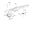
以下、図1等を参照して、本発明の一実施形態に係る虚像表示装置について説明する。なお、虚像表示装置が左右一対の対称構造となっていることから、図示では、代表して左眼側に対応するものだけを表示し、右眼側を省略しているが、右眼側にも同様の構成を有する。まず、図1に概念的に概略を示すように、本実施形態に係る虚像表示装置100は、ヘッドマウントディスプレイに適用されるものであり、画像形成ユニット10と、表示光学系2とを一組として備える。画像形成ユニット10は、画像を表示するための映像光GLを形成し、表示光学系2は、画像形成ユニット10を経た映像光GLによって形成した虚像を観察者の眼EYに入射させる。以上により、虚像表示装置100は、映像光GLを観察者の眼EYの前まで導いて、観察者に虚像を視認させる。
Hereinafter, the virtual image display device according to the embodiment of the present invention will be described with reference to FIG. 1 and the like. Since the virtual image display device has a pair of symmetrical structures on the left and right, in the figure, only the device corresponding to the left eye side is displayed as a representative, and the right eye side is omitted, but the right eye side is used. Has a similar configuration. First, as conceptually outlined in FIG. 1, the virtual
図1、図2A及2Bに示すように、虚像表示装置100のうち、画像形成ユニット10は、各映像素子11R,11B,11Gと、光合成用のプリズムである合成光学系PRとを備え、映像光GLを形成する。
As shown in FIGS. 1, 2A and 2B, in the virtual
各映像素子11R,11B,11Gは、画像を表示する画像表示部として、本体部分であるパネル部で画像形成を行うとともに形成された画像光である映像光GLとなるべき各色光を射出する装置である。各映像素子11R,11B,11Gのうち、映像素子11Rは、赤色波長帯域の光を射出する第1映像素子であり、映像素子11Bは、青色波長帯域の光を射出する第2映像素子であり、映像素子11Gは、緑色波長帯域の光を射出する第3映像素子である。
Each of the
各映像素子11R,11B,11Gは、例えば有機EL等の自発光型の素子(OLED)で構成される映像素子により構成することができる。この場合、光源までを含めて一体化された部材として構成できる。なお、各映像素子11R,11B,11Gを、例えば透過型の液晶パネルといった空間光変調装置のほか、照明光を射出するバックライトである照明装置(不図示)や動作を制御する駆動制御部(不図示)を有することで構成してもよい。また、本実施形態では、各映像素子11R,11B,11Gとして、一辺の長さを1インチ以下とするマイクロディスプレイをパネルに採用することが考えられる。
Each
上記の場合、各映像素子11R,11B,11Gは、各色の波長帯域での画像形成を行うため、例えばカラーフィルターを使用するいわゆる単板式の映像素子の場合に比べて光の利用効率を改善できる。さらに、有機EL(OLED)を使用した場合、発光体の作製において、単板式のように赤青緑の素子を順に並べて配列していく、といったことを要せず、対応する各色について構成すればよいため、単板式の場合に比べて、より高精細な構成とすることも期待できる。なお、図示のように、各映像素子11R、11B,11Gは、合成光学系PRの各面に貼り付けられている。
In the above case, since each
合成光学系PRは、各映像素子11R、11B,11Gで変調された色光を合成して映像光GLとするクロスダイクロイックプリズムである。すなわち、合成光学系PRは、図示のように、4つの三角柱状のプリズム部材を貼り合わせて形成される四角柱状の部材である。より具体的に説明すると、まず、上記した4つの三角柱状のプリズム部材は、合同な形状であって、底面が直角二等辺三角形となっている。当該底面の直角部分の頂点が揃うように4つの三角柱状のプリズム部材の側面を貼り合わせることで、四角柱状の部材となる。この場合、当該底面の頂点に沿った稜線が重なり合って1つの交差軸が形成されることになる。また、各三角柱状のプリズム部材の側面である貼り合わせ部分には、例えば、誘電体多層膜で構成されるダイクロイック膜によって2つの交差する反射面を形成させている。ここでは、第1映像素子11Rと第2映像素子11Bとからの光をそれぞれ射出させつつ他の成分を透過させるべく、第1反射面である第1ダイクロイック膜DM1と、第2反射面である第2ダイクロイック膜DM2とがそれぞれ形成されている。つまり、第1ダイクロイック膜DM1(第1の合成面)と第2ダイクロイック膜DM2(第2の合成面)とは、各映像素子11R、11B,11Gからの色光を合成させる合成面として機能する。各ダイクロイック膜DM1,DM2は、上記構成により、合成光学系PRのうち各映像素子11R、11B,11Gが貼付された側面SS1〜SS3に対して、45°傾いた状態で、かつ、互いに90°で交差するように配置されていることになる。ここで、三角柱状のプリズム部材の底面の頂点に沿った稜線が重なり合って形成される1つの交差軸を、すなわち、第1ダイクロイック膜DM1と第2ダイクロイック膜DM2とが交差して形成される交差軸を、クロス軸CXとする。また、合成光学系PRにおいて、クロス軸CXの延びる方向をY方向とし、映像光の射出方向をZ方向とする。なお、上記のように規定したY方向及びZ方向に対して、右手系とした場合のY方向及びZ方向に垂直な方向をX方向としている。
The composite optical system PR is a cross-dichroic prism that synthesizes colored light modulated by each of the
以下、図2Bを参照して、各映像素子11R、11B,11Gと合成光学系PRとの配置関係について説明する。まず、図示のように、各映像素子11R、11B,11Gは、交差軸であるクロス軸CXに沿った方向を長辺方向とする矩形状となっている。すなわち、各映像素子11R、11B,11Gにおける光射出面は、クロス軸CXに沿った方向であるY方向を長辺方向とし、これに垂直な方向を短辺方向とする矩形状である。図示の場合、第1及び第2映像素子11R,11Bは、Z方向を短辺方向とし、第3映像素子11Gは、X方向を短辺方向としている。
Hereinafter, the arrangement relationship between the
以下、図3を参照して、画像形成ユニット10における各色光の光路について説明しつつ、色光の合成について、すなわち映像光GLの形成について説明する。まず、合成光学系PRの第1側面SS1に貼付された第1映像素子11Rから射出された赤色光Lrは、第1ダイクロイック膜DM1において反射され、光射出面SSEに向かう。なお、赤色光Lrは、第2ダイクロイック膜DM2については、透過する。
Hereinafter, with reference to FIG. 3, the optical path of each colored light in the
一方、合成光学系PRの第2側面SS2に貼付された第2映像素子11Bから射出された青色光Lbは、第2ダイクロイック膜DM2において反射され、光射出面SSEに向かう。なお、青色光Lbは、第1ダイクロイック膜DM1については、透過する。
On the other hand, the blue light Lb emitted from the
最後に、合成光学系PRの第3側面SS3に貼付された第3映像素子11Gから射出された緑色光Lgは、第1及び第2ダイクロイック膜DM1,DM2をともに透過し、光射出面SSEに向かう。
Finally, the green light Lg emitted from the
以上のようにして透過反射された各色光Lr,Lb,Lgが合成されて、映像光GLとして、光射出面SSEから射出される。 The light Lr, Lb, and Lg of each color transmitted and reflected as described above are combined and emitted from the light emitting surface SSE as the image light GL.
図1に戻って、虚像表示装置100のうち、表示光学系2は、投射光学系12と、導光光学系20とを有する。なお、図示では、投射光学系12の光軸AX上を通過する映像光GLについて示している。
Returning to FIG. 1, the display
投射光学系12は、図1において概念的・抽象的に示しているが、実際には、単レンズまたは複数のレンズ群から構成され、画像形成ユニット10を経た映像光GL、すなわち合成光学系PRを経た映像光GLを、導光光学系20に向けて投射する。なお、図4を参照して後述する一例においては、投射光学系12を3つのレンズL1〜L3で構成したものとして例示している。
Although the projection
導光光学系20は、投射光学系12からの映像光GLを内部反射させつつ、射出することで、観察者の眼前に導く導光部材、あるいは導光装置である。
The light guide
以下、図4を参照して、本実施形態に係る虚像表示装置100の具体的一構成とその光路についての一例を説明する。
Hereinafter, with reference to FIG. 4, an example of a specific configuration of the virtual
図4の一例では、投射光学系12は、3つのレンズL1〜L3で構成されている。また、導光光学系20は、映像光を取り込む入射部21と、導光用の平行導光体22と、映像光を取り出すための射出部23とを備える。
In one example of FIG. 4, the projection
入射部21は、観察者の耳側に配置され、射出部23は、観察者の鼻側に配置される。平行導光体22と入射部21の本体とは、高い光透過性を有する樹脂材料により成形された一体品又は一部材である。なお、平行導光体22は、観察者の眼EYを基準とする光軸OXに対して傾けて配置されている。この場合、平行導光体22を顔の曲線に沿って配置できる。
The
入射部21は、投射光学系12からの映像光GLを取り込む光入射面ISと、取り込んだ映像光GLを反射して平行導光体22内に導く反射面RSとを有する。光入射面ISは、投射光学系12側に凹の曲面で形成されており、反射面RSで反射された映像光GLを内面側で全反射する機能も有する。反射面RSは、投射光学系12側に凹の曲面で形成されている。反射面RSは、曲面上にアルミ蒸着等の成膜を施すことにより形成され、光入射面ISから入射した映像光GLを反射し光路を所定方向に折り曲げる。光入射面ISは、反射面RSで反射された映像光GLを内側で全反射し光路を所定方向に折り曲げる。なお、各面を形成する曲面は、非軸対称自由曲面であるが、これに限らず、軸対称自由曲面、球面、非球面等とすることができる。また、各曲面は、投射光学系12によるコリメート機能を補助することができる。
The
平行導光体22は、平板部分であり、平行に延びる一対の面である2つの対向する平面22a,22bを有する。両平面22a,22bは、平行平面であるため、外界像に関して拡大やフォーカスズレを生じさせない。平行導光体22のうち一方の平面22aは、入射部21からの映像光を全反射させる全反射面として機能し、映像光を少ない損失で射出部23に導く役割を有する。裏側の平面22bは、平行導光体22と射出部23との境界面となっている。
The parallel
射出部23は、平行導光体22の奥側すなわち観察者の鼻側において、裏側の平面22bに沿ってその延長上に層状に形成された部材であり、透過性を有する複数のミラー等を配列してなる反射ユニットを有する。これにより、射出部23は、平行導光体22の全反射面である外界側の平面22aにおいて全反射された映像光GLを通過させる際に、入射した映像光GLを所定角度で反射して光射出面OS側へ折り曲げる。
The injection unit 23 is a member formed in layers on the back side of the parallel
なお、光路上における導光光学系20の各光学面を、光路下流側から順に以下のようにする。まず、平行導光体22の平面22b又は光射出面OSを第1面S1とし、平面22aを第2面S2とする。次に、入射部21の光入射面ISについて全反射による反射面として捉える場合を第3面S3とする。さらに、入射部21の反射面RSを第4面S4とする。最後に、光入射面ISについて光を取り込む面として捉える場合を第5面S5とする。
Each optical surface of the light guide
以下、映像光GLの光路に沿って、図4に示す虚像表示装置100の動作について簡単に説明する。なお、図中において、光射出面11aは、画像形成ユニット10において合成された映像光GLの射出位置を仮想的に示しており、第3映像素子11G(図3等参照)の光射出面に相当する。
Hereinafter, the operation of the virtual
まず、画像形成ユニット10の光射出面11aから射出された映像光GLは、3つのレンズL1〜L3で構成される投射光学系12を経て、導光光学系20に向けて射出される。映像光GLは、導光光学系20の第5面S5から入射すると、第4面S4で反射され、さらに、第3面S3及び第2面S2においてそれぞれ全反射されて、第1面S1に到達し、折り曲げられつつ観察者の眼EYに向けて射出される。すなわち、導光光学系20により導光されることで、観察者の眼EYまで到達する。眼EYの位置に達するに際して、映像光GLの各成分は平行化された光線束となっており、かつ、眼EYの位置において重畳して入射する。観察者は、光の入射方向あるいは入射角度をもって、画像位置を識別し、虚像を視認することになる。この場合、眼EYの位置において重畳している各光線束の断面形状が、アイリング形状となり、その径がアイリング径となる。
First, the image light GL emitted from the
なお、上記構成の場合、第1面S1〜第5面S5の一部に自由曲面を設けることで、投射光学系12の負担を低減でき、結果として光学系を薄くできる。また、光学設計に際しては、上記と逆の順すなわち、眼EYの位置を最初の基準として、第1面S1側から順に光路を追うことで、各部の設定がなされる。
In the case of the above configuration, by providing a free curved surface on a part of the first surface S1 to the fifth surface S5, the load on the projection
以上のような構成により、画像形成ユニット10を構成する合成光学系PRにおいて合成された映像光GLが、確実に観察者の眼前側まで導かれる。
With the above configuration, the image light GL synthesized in the synthetic optical system PR constituting the
ここで、上記のような映像光GLの各光学系による導光を経る前と経た後とを比較した場合において、画像形成ユニット10における合成における透過反射の向きを考える場合の基準として利用可能であるクロス軸CX(図2等参照)の延びる方向すなわちクロス軸CXの軸方向は、観察者にとっての水平方向すなわち左右の眼の並ぶ方向に対応するものとなっている。図5は、合成光学系PRの交差軸であるクロス軸CXと観察者の眼EYの並びとの関係を説明するための概念図である。なお、図5では、虚像表示装置100を左右一対の構成で示している。
Here, when comparing before and after passing through the light guide by each optical system of the image light GL as described above, it can be used as a reference when considering the direction of transmitted reflection in the composition in the
図示のように、左右一対の画像形成ユニット10a,10bの各々において、合成光学系PR,PRにおける合成面の交差軸であるクロス軸CX,CXは、観察者が視認する虚像画面IMa,IMb上では、水平方向すなわち横方向に延びる仮想軸CXa,CXbに相当する。したがって、クロス軸CXの延びる方向A1は、各仮想軸CXa,CXbの延びる方向A2に対応し、各仮想軸CXa,CXbの延びる方向A2は、観察者の鼻NSを挟んで左右の眼EY,EYの並ぶ方向B1に対応するものとなっている。すなわち、方向A1が方向B1に沿った方向になっている。このような関係にあることで、本実施形態では、適切なアイリング径を形成させて視認上において虚像が欠け難いようにしたり、各光学系の小型化、延いては装置の小型化を図ったりすることが可能になっている。なお、図示において、左眼EYに対応する画像形成ユニット10aにおけるクロス軸CXの延びる方向をYL方向とし、映像光の射出方向をZL方向とする。なお、上記のように規定したYL方向及びZL方向に対して、右手系とした場合のYL方向及びZL方向に垂直な方向をXL方向としている。同様にして、右眼EYに対応する画像形成ユニット10bにおけるクロス軸CXの延びる方向をYR方向とし、ZR方向及びXR方向が規定できる。
As shown in the figure, in each of the pair of left and right
以下、図6を参照して、本実施形態における光学系により形成されるアイリング径について説明する。図6は、形成されるアイリング形状について一例を概念的示している。特に、図6において一部拡大して示すように、本実施形態では、眼EYの位置におけるアイリング形状RFが、観察者の眼の並ぶ方向を長軸方向とする形状となっている。つまり、アイリング形状RFのアイリング径について、眼EYの並ぶ方向についての径R1が、これに垂直な方向についての径R2よりも大きくなっている。ここでは、一例として、アイリング形状RFが、眼の並ぶ方向を長軸方向とする楕円形状、すなわち横方向に長い楕円形状となっている。 Hereinafter, the eye ring diameter formed by the optical system in the present embodiment will be described with reference to FIG. FIG. 6 conceptually shows an example of the formed eye ring shape. In particular, as shown in a partially enlarged view in FIG. 6, in the present embodiment, the eye ring shape RF at the position of the eye EY has a shape in which the direction in which the observer's eyes are lined up is the major axis direction. That is, with respect to the eye ring diameter of the eye ring shape RF, the diameter R1 in the direction in which the eye EYs are lined up is larger than the diameter R2 in the direction perpendicular to this. Here, as an example, the eye ring shape RF has an elliptical shape whose major axis direction is the direction in which the eyes are lined up, that is, an elliptical shape that is long in the lateral direction.
一般に、人間の眼は、横方向についての視野が縦方向よりも広い。したがって、画像表示おいても、上述してきたように例えば横長の矩形形状とすることが多い。つまり、図6に示すように、虚像画面IMは横長となり、横方向についての画角θ1が縦方向についての画角θ2よりも大きくなっていることが望ましい。さらに、人間の眼はその特性上左右によく動き、また、左右の眼の並び具合については、個人差がある。以上のような理由から、画像の欠けが無いように、すなわち光が眼に届くようにするためには、特に眼の並ぶ方向である横方向についての映像光のアイリング径を大きくとることが重要となる。見方を変えると、眼の並ぶ方向に垂直な方向である縦方向については、横方向ほどには、アイリング径を要しないと考えられる。図6において、アイリング形状RFの短辺と長辺とである径R2と径R1との比を、例えば、1:2程度にすれば、横長の映像において欠けも無く、また、眼幅のバラツキにも対応できると考えられる。また、アイリング形状RFを楕円とすることにより、眼EYの方向に映像を偏向させるミラー等の各部の大きさも小さくできる。 In general, the human eye has a wider field of view in the horizontal direction than in the vertical direction. Therefore, even in the image display, as described above, for example, a horizontally long rectangular shape is often used. That is, as shown in FIG. 6, it is desirable that the virtual image screen IM is horizontally long, and the angle of view θ 1 in the horizontal direction is larger than the angle of view θ 2 in the vertical direction. Furthermore, the human eye moves well to the left and right due to its characteristics, and there are individual differences in the alignment of the left and right eyes. For the above reasons, in order to prevent the image from being chipped, that is, to allow the light to reach the eyes, it is necessary to increase the eye ring diameter of the image light in the lateral direction, which is the direction in which the eyes are lined up. It becomes important. From a different point of view, it is considered that the vertical direction, which is the direction perpendicular to the direction in which the eyes are lined up, does not require the eye ring diameter as much as the horizontal direction. In FIG. 6, if the ratio of the diameter R2 and the diameter R1 which are the short side and the long side of the eye ring shape RF is set to, for example, about 1: 2, there is no chipping in the horizontally long image, and the eye width is widened. It is thought that it can handle variations. Further, by making the eye ring shape RF an ellipse, the size of each part such as a mirror that deflects the image in the direction of the eye EY can be reduced.
そこで、本実施形態では、図7A及び7Bに例示するように、上記アイリング径の方向に対応する方向によって、光射出側である各映像素子11R,11B,11Gにおける発散角を調整している。さらに、例えば表示光学系2において、光射出側での発散角の関係を維持しつつ映像光を導くことで、図6に例示したような楕円形状のアイリングの形成を可能としている。
Therefore, in the present embodiment, as illustrated in FIGS. 7A and 7B, the divergence angles of the
以下、図7A及び7Bを参照して、映像光の広がりを示す発散角について説明する。なお、図7A及び7Bは、各映像素子11R,11B,11Gのうち、第3映像素子11Gについて一部を拡大して示しており、図7Aは、合成光学系PRの側面SS3に貼付された第3映像素子11Gのうち長辺側のパネル端TLから射出される映像光GLとなるべき緑色光Lgとその発散角αの様子について概念的に示している。すなわち、図示において、Y方向は、矩形の第3映像素子11Gの長辺方向であり、この方向は、クロス軸CX(図2等参照)の延びる方向すなわち軸方向に平行なY方向となっている。
Hereinafter, the divergence angle indicating the spread of the image light will be described with reference to FIGS. 7A and 7B. 7A and 7B show a part of the
一方、図7Bは、第3映像素子11Gのうち短辺側のパネル端TSから射出される緑色光Lgとその発散角βの様子について概念的に示している。すなわち、図示において、X方向は、矩形の第3映像素子11Gの短辺方向であり、この方向は、クロス軸CX(図2等参照)の延びる方向すなわち軸方向に垂直なX方向となっている。
On the other hand, FIG. 7B conceptually shows the state of the green light Lg emitted from the panel end TS on the short side side of the
以上の場合において、発散角αが発散角βよりも大きくなっている。このような発散角の特性を有する映像光を利用することの結果として、例えば図6に例示したような楕円形状のアイリングの形成が可能になっている。ここでは、一例として、発散角αについては、10度あるいは10度程度となっており、発散角βについては、7度あるいは7度程度となっているものとする。以上のような広がりを有することで、映像が欠けないようにする、という観点において、所望の形状の光線束となる映像光GL、延いては所望のアイリング径となる虚像の形成が可能になる。 In the above cases, the divergence angle α is larger than the divergence angle β. As a result of using the image light having such a characteristic of the divergence angle, it is possible to form an elliptical eye ring as illustrated in FIG. 6, for example. Here, as an example, it is assumed that the divergence angle α is about 10 degrees or 10 degrees, and the divergence angle β is about 7 degrees or 7 degrees. By having the above-mentioned spread, from the viewpoint of preventing the image from being chipped, it is possible to form an image light GL having a desired shape of a light beam bundle and a virtual image having a desired eye ring diameter. Become.
なお、図7Aに示すような長辺側のパネル端TLから発散角αで射出される成分を考慮することで、合成光学系PRのサイズが定まる。すなわち、図示のように、パネル端TLから発散角αで射出される成分が、光射出面SSEにおいて含まれるように十分なマージンMGをY方向すなわち横方向に設けておく必要がある。つまり、図示のように、光射出方向であるZ方向についての合成光学系PRの一辺の長さを長さLとすると、光射出面SSEでの光線束の広がりの幅は、L×tanαとなる。したがって、マージンMGは、パネル端TLの位置からY方向についてL×tanα以上設けられるように確保する必要があることになる。本実施形態では、例えば図2Bを参照すれば明らかなように、Z方向については、第3映像素子11G以外の2つの映像素子11R,11Bの短辺方向となっている。したがって、長さLを後述す比較例の場合(図10参照)に比べて小さくすることができる。このため、上記したL×tanαの値、すなわちマージンMGの大きさを小さく抑えることができ、延いては、合成光学系PRのサイズを小さくできる。
The size of the composite optical system PR is determined by considering the component emitted from the panel edge TL on the long side as shown in FIG. 7A at the divergence angle α. That is, as shown in the drawing, it is necessary to provide a sufficient margin MG in the Y direction, that is, in the lateral direction so that the component emitted from the panel edge TL at the divergence angle α is included in the light emission surface SSE. That is, as shown in the figure, assuming that the length of one side of the composite optical system PR in the Z direction, which is the light emission direction, is length L, the width of the spread of the light flux on the light emission surface SSE is L × tan α. Become. Therefore, it is necessary to secure the margin MG so as to be provided in L × tan α or more in the Y direction from the position of the panel end TL. In the present embodiment, as is clear from reference to FIG. 2B, for example, the Z direction is the short side direction of the two
ここで、上記のような発散角を有する場合、第3映像素子11G以外の2つの映像素子11R,11Bについては、第1及び第2ダイクロイック膜DM1,DM2での反射特性についても考慮する必要がある。各ダイクロイック膜DM1,DM2の反射特性は、設定された光の入射角度に対して最も高い適正を示すように作製される。図示の場合、各ダイクロイック膜DM1,DM2は、2つの映像素子11R,11Bに対して45°傾けているので、45°で入射する成分について対応する波長帯域の成分を効率よく反射するとともに他の波長帯域の成分を透過させ、各膜が高精度に色分離を行うことで、合成光学系PR全体として高性能な色合成が可能となっている。したがって、45°から大きく離れた入射角度で入射する成分については、良好な映像を視認するに足る十分に高い反射率を維持できない可能性がある。つまり、2つの映像素子11R,11Bから入射する成分のうち、各ダイクロイック膜DM1,DM2での入射角度が45°から大きく異なる値となるものが色分離あるいは色合成上の問題となりうる。
Here, when the divergence angle is as described above, it is necessary to consider the reflection characteristics of the first and second dichroic films DM1 and DM2 for the two
図8は、図7Bに対応する図であり、第1映像素子11Rの短辺側のパネル端TSから射出される映像光GLとなるべき赤色光Lrとその発散角βの様子について概念的に示している。なお、第2映像素子11Bについても第2ダイクロイック膜DM2との関係において、下記と同様であるので、図示及び説明を省略する。
FIG. 8 is a diagram corresponding to FIG. 7B, conceptually showing the state of the red light Lr and its divergence angle β, which should be the image light GL emitted from the panel end TS on the short side side of the
図示の場合、赤色光Lrは、45°傾いている第1ダイクロイック膜DM1に入射するが、発散角βの差が入射角度の差として、そのまま影響することになる。すなわち、光の入射角度が45°±βの範囲を有することになる。一方、図示を省略するが、発散角αに関しては、Y方向すなわちクロス軸CXに沿った方向についての広がりであるため、第1ダイクロイック膜DM1での反射において、図8に示すような大きな影響が出ないものとなっている。本実施形態では、発散角βの値が発散角αよりも小さい、具体的な例示としては7°程度に抑えられている。これにより、第1ダイクロイック膜DM1での反射特性によって反射率が急激に低下することで画像の色むらや明暗の差が生じる、さらには画像が欠ける、といった事態を回避している。 In the case of the figure, the red light Lr is incident on the first dichroic film DM1 inclined by 45 °, but the difference in the divergence angle β has an effect as it is as the difference in the incident angle. That is, the incident angle of light has a range of 45 ° ± β. On the other hand, although not shown, the divergence angle α is a spread in the Y direction, that is, in the direction along the cross axis CX, so that the reflection on the first dichroic film DM1 has a large effect as shown in FIG. It does not come out. In the present embodiment, the value of the divergence angle β is smaller than the divergence angle α, and as a specific example, it is suppressed to about 7 °. As a result, it is possible to avoid a situation in which the reflectance is sharply lowered due to the reflection characteristics of the first dichroic film DM1 to cause color unevenness and a difference in brightness of the image, and further, the image is chipped.
図9は、反射面である第1及び第2ダイクロイック膜DM1,DM2における波長ごとの反射特性の一例について示すグラフであり、横軸を入射する光の波長(単位:nm)、縦軸を入射した光の反射率(単位:%)としている。各曲線は、プロジェクター用クロスダイクロイックプリズムを構成するダイクロイック膜等に用いられる一般的なダイクロミラー特性を示しており、光の入射角度での反射特性を示している。この場合、例えば、波長の大きい側での反射特性の変化が、赤色光Lrの反射に影響し、波長の小さい側での反射特性の変化が、青色光Lbの反射に影響することになる。また、入射角度については、発散角の影響による角度変化の範囲を考慮して、45°−8°=37°から45°+8°=53°までとして、いくつかの代表的な値を選択して表示している。具体的には、図9において、例えば、波長の大きい側で反射率が変化する曲線群Rrは、第1ダイクロイック膜DM1の反射透過特性を示しており、入射角度が37°、41°、45°、49°及び53°での反射特性を示す5本の曲線である。一方、波長の小さい側で反射率が変化する曲線群Brは、第2ダイクロイック膜DM2の反射透過特性を示しており、入射角度が37°、41°、45°、49°及び53°での反射特性を示す5本の曲線である。 FIG. 9 is a graph showing an example of reflection characteristics for each wavelength in the first and second dichroic films DM1 and DM2, which are reflection surfaces. The horizontal axis is the wavelength of light incident (unit: nm), and the vertical axis is incident. The reflectance of the light (unit:%) is used. Each curve shows general dichroic mirror characteristics used for a dichroic film or the like constituting a cross dichroic prism for a projector, and shows reflection characteristics at an incident angle of light. In this case, for example, a change in the reflection characteristic on the side having a large wavelength affects the reflection of the red light Lr, and a change in the reflection characteristic on the side having a small wavelength affects the reflection of the blue light Lb. Regarding the incident angle, considering the range of angle change due to the influence of the divergence angle, some typical values were selected from 45 ° -8 ° = 37 ° to 45 ° + 8 ° = 53 °. Is displayed. Specifically, in FIG. 9, for example, the curve group Rr whose reflectance changes on the larger wavelength side shows the reflection and transmission characteristics of the first dichroic film DM1, and the incident angles are 37 °, 41 °, and 45. Five curves showing reflection characteristics at °, 49 ° and 53 °. On the other hand, the curve group Br whose reflectance changes on the smaller wavelength side shows the reflection and transmission characteristics of the second dichroic film DM2, and the incident angles are 37 °, 41 °, 45 °, 49 ° and 53 °. There are five curves showing the reflection characteristics.
ここで、グラフから明らかなように、反射特性は、入射角度によって大きな波長依存性を有し、角度範囲が広がるほど色分離の性能が悪くなる。一方、映像光の形成に際しては、赤色及び青色の波長帯域については、90%以上さらに望ましくは95%以上の高い反射率を維持し、緑色の波長帯域については、10%さらに望ましくは5%以下とすることで、高い透過率を維持したい、といった場合が想定される。このように高い色分離性の条件を満たすための波長範囲を確保しようとすると、例えば、反射による青色光の取り出し範囲が矢印ARbとなり、透過による緑色光の取り出し範囲が矢印ARgとなり、反射による赤色光の取り出し範囲が矢印ARrとなる、といった具合になる。つまり、入射角の角度範囲を制限するか、使用する波長帯域を狭くするかしないと、適切な色分離ができなくなる可能性があることがグラフから分かる。 Here, as is clear from the graph, the reflection characteristic has a large wavelength dependence depending on the incident angle, and the color separation performance deteriorates as the angle range widens. On the other hand, when forming video light, a high reflectance of 90% or more, more preferably 95% or more is maintained for the red and blue wavelength bands, and 10%, more preferably 5% or less for the green wavelength band. By doing so, it is assumed that there is a case where a high transmittance is to be maintained. In order to secure a wavelength range for satisfying the condition of high color separation, for example, the blue light extraction range due to reflection becomes the arrow ARb, the green light extraction range due to transmission becomes the arrow ARg, and the red light due to reflection. The light extraction range is the arrow ARr, and so on. That is, it can be seen from the graph that proper color separation may not be possible unless the angle range of the incident angle is limited or the wavelength band used is narrowed.
これに対して、本実施形態では、上記のような入射角度の幅に影響を与えにくいクロス軸CXに沿った方向について発散角を例えば10°程度と比較的大きく取る一方で、発散角が入射角度に大きく影響を与えるクロス軸CXに垂直な方向については、発散角を例えば7°程度と比較的小さく抑えている。クロス軸CXに垂直な方向についての発散角を小さく抑えておくことで、画像形成ユニット10は、高い反射透過特性を維持しつつ、利用可能な波長帯域すなわち許容可能な波長帯域を広く維持できる。つまり、第1及び第2ダイクロイック膜DM1,DM2における反射特性に応じて、下記色光Lr,Lb,Lgの発散角及び波長帯域幅を定めることで、良好な画像形成を確保している。
On the other hand, in the present embodiment, the divergence angle is relatively large, for example, about 10 °, in the direction along the cross axis CX, which does not easily affect the width of the incident angle, while the divergence angle is incident. In the direction perpendicular to the cross axis CX, which greatly affects the angle, the divergence angle is kept relatively small, for example, about 7 °. By keeping the divergence angle in the direction perpendicular to the cross-axis CX small, the
なお、発散角については、上記のようなクロス軸CXに沿った方向に関するものとクロス軸CXに垂直な方向に関するものとの他に、これらの双方の成分を含んだ斜め方向に進む光の成分についても考慮する必要があると考えられる。しかし、これらの成分の第1及び第2ダイクロイック膜DM1,DM2に対する傾きは、クロス軸CXに垂直な方向についての傾きからそれほど大きく変わらない。例えば、第1ダイクロイック膜DM1あるいは第2ダイクロイック膜DM2に対する入射角度が、クロス軸CXに垂直な方向であるX方向について、45°+7°=52°となり、さらに、クロス軸CXの軸方向であるY方向に10°となっている方向に射出される成分であっても、実効の入射角度は、52.677°であることが計算上分かる。すなわち、このような斜め方向であっても実効の角度は、クロス軸CXに垂直な方向についての傾き具合と比べてそれほど増えない。これは、X方向に発散する角度については、そのまま基準の45°に対して加減算される一方、クロス軸CXに平行なY方向に発散する角度については、ほとんど入射角度に影響を与えないためである。したがって、クロス軸CXに垂直な方向であるX方向についての発散角の範囲を考慮し、例えばこれに若干のマージンをもたせておけば、所望の透過反射特性を有する合成膜を合成光学系PRにおいて形成させることができると考えられる。 Regarding the divergence angle, in addition to the one related to the direction along the cross axis CX and the one related to the direction perpendicular to the cross axis CX as described above, a component of light traveling in an oblique direction including both of these components. It is considered necessary to consider. However, the inclinations of these components with respect to the first and second dichroic films DM1 and DM2 are not so different from the inclinations in the direction perpendicular to the cross axis CX. For example, the angle of incidence on the first dichroic film DM1 or the second dichroic film DM2 is 45 ° + 7 ° = 52 ° in the X direction, which is the direction perpendicular to the cross axis CX, and is further the axial direction of the cross axis CX. It can be calculated that the effective incident angle is 52.677 ° even if the component is ejected in the direction of 10 ° in the Y direction. That is, even in such an oblique direction, the effective angle does not increase so much as compared with the degree of inclination in the direction perpendicular to the cross axis CX. This is because the angle diverging in the X direction is added or subtracted as it is with respect to the reference 45 °, while the angle diverging in the Y direction parallel to the cross axis CX has almost no effect on the incident angle. be. Therefore, if the range of the divergence angle in the X direction, which is the direction perpendicular to the cross axis CX, is taken into consideration and, for example, a slight margin is provided in this range, a synthetic film having desired transmission / reflection characteristics can be obtained in the synthetic optical system PR. It is thought that it can be formed.
以下、図10を参照して、本実施形態の比較例について説明する。図10は、比較例について説明するための概念図であり、図5の一部に対応する図である。比較例では、図示のように、本実施形態と異なり、画像形成ユニット10において、クロス軸CXの延びる方向A1が眼EYの並ぶ方向B1に沿った方向となっておらず、方向B1に対して垂直な方向となっている。この場合、例えば、画像形成ユニット10の奥行方向(Z方向)が、第1及び第2映像素子11R,11Bにとっての長辺方向となるため、この方向について大型化する必要があり光学系を大きくしなければならなくなる。さらに、図7Aを参照して考慮したマージンMGの観点においても不利である。さらに、本比較例の場合、第1及び第2映像素子11R,11Bの長辺方向がクロス軸CXに対して垂直な方向に延びているため、図8及び図9を参照して考慮した事項から考えると、長辺方向について合成光学系PRの反射における発散角に伴う反射角度の差が大きくなってしまう。このため、発散角が大きくなる成分で反射特性が悪くなるおそれが高まり、アイリング径を確保する上でも不利になる。これに対して、本実施形態では、かかる事態を回避し、良好な画像形成をしつつ、装置の小型化を図ることができる。
Hereinafter, a comparative example of the present embodiment will be described with reference to FIG. FIG. 10 is a conceptual diagram for explaining a comparative example, and is a diagram corresponding to a part of FIG. In the comparative example, as shown in the figure, unlike the present embodiment, in the
以下、図11を参照して、本実施形態に係る虚像表示装置の一変形例について説明する。図11は、一変形例の虚像表示装置100の構成及び光路について説明するための平面図であり、図4に対応する図である。
Hereinafter, a modified example of the virtual image display device according to the present embodiment will be described with reference to FIG. FIG. 11 is a plan view for explaining the configuration and the optical path of the virtual
図示のように、本変形例の虚像表示装置100は、画像形成ユニット10と、表示光学系2とを一組として備え、表示光学系2は、投射光学系12と、導光光学系420とを有する。画像形成ユニット10は、上記と同様の構成を有する。また、投射光学系12は、上記と同様に、3つのレンズL1〜L3で構成されている。また、虚像表示装置100は、導光光学系420として、導光及び透視用の導光部材20aと、透視用の光透過部材20bとを有する。これらのうち、導光部材20aは、入射部21と平行導光体22とを有し、光透過部材20bは、平行導光体22に固定されている。
As shown in the figure, the virtual
導光部材20aの入射部21は、投射光学系12からの映像光GLを取り込む光入射面ISと、取り込んだ映像光GLを反射して平行導光体22内に導く反射面RSとを有する。
The
導光部材20aの平行導光体22は、射出側に曲面の光学面22cを有する。光学面22cの表面には、ハーフミラー層25が付随して設けられている。このハーフミラー層25は、光透過性を有する反射膜すなわち半透過反射膜であり、金属反射膜や誘電体多層膜を成膜することにより形成され映像光に対する反射率が適宜設定されている。
The parallel
光透過部材20bは、導光部材20aに設けた一対の平面22a,22bを延長上に配置される平面122a,122bを有し、これらの平面122a,122bの間に光学面122cを有している。光学面122cは、導光部材20aの光学面22cに対して接合され一体化されている曲面である。
The
導光光学系420において、導光部材20aは、光透過部材20bと接着層CCを介して接合されており、接着層CCは、ハーフミラー層25のある画像取り出しエリアAAにおいて、ハーフミラー層25よりも光透過部材20b側に存在する。画像取り出しエリアAAは、使用者の眼に対して画像光が射出される領域となっている。
In the light guide
以下、映像光GLの光路に沿って、図11に示す虚像表示装置100の動作について簡単に説明する。なお、図中において、光射出面11aは、画像形成ユニット10において合成された映像光GLの射出位置を仮想的に示しており、第3映像素子11G(図3等参照)の光射出面に相当する。
Hereinafter, the operation of the virtual
まず、画像形成ユニット10の光射出面11aから射出された映像光GLは、3つのレンズL1〜L3で構成される投射光学系12を経て、導光光学系420に向けて射出される。映像光GLは、導光光学系420の光入射面ISを形成する曲面21bから入射すると、反射面RSを形成する曲面21aで反射され、さらに、曲面21b、平面22a及び平面22bにおいてそれぞれ全反射されて、光学面22cに到達し、ハーフミラー層25において反射された一部の成分が画像を視認させるべき映像光として取り出され、観察者の眼EYに向けて射出される。すなわち、導光光学系420により導光されることで、観察者の眼EYまで到達する。
First, the image light GL emitted from the
本変形例においても、眼の並ぶ方向とクロス軸の方向とについては、上記と同様に対応した関係となっている。 In this modified example as well, the direction in which the eyes are lined up and the direction of the cross axis correspond to each other in the same manner as described above.
また、図示のような構成の場合、例えば映像素子で構成される画像形成ユニット10からの光の発散角について、クロス軸の方向とクロス軸に垂直な方向が等しい場合であっても、表示光学系2の投射光学系12において光を取り込む角度範囲の調整を行うことで、光の発散角をクロス軸の方向についてクロス軸に垂直な方向よりも大きくなるようにして観察者の眼EYに向けて射出させることができる。
Further, in the case of the configuration as shown in the drawing, for example, the display optics of the light divergence angle from the
以下、上記を可能とするための態様等について説明する。まず前提として、例えば、図7A及び7Bに対応する図12A及び12Bに示すように、アイリング径の方向に対応する方向によって、光射出側である各映像素子11R,11B,11Gにおける発散角が等方的であるものとする。すなわち、図7A及び7Bに示した場合と異なり、例えば方向ごとの特定の調整といったことがなされずに、発散角αと発散角βとが等しい、あるいはほぼ等しい状態となっているものとする。このような場合において、図11に示す絞りSTの位置、すなわち、導光光学系420の光入射面ISよりも投射光学系12側であって、画像形成ユニット10から射出される光の主光線が交わる位置において、絞りSTの形状を、例えば図13のような横長の楕円形状であるものとする。すなわち、クロス軸の方向に対応する横方向についての内径IR1を、クロス軸に垂直な方向に対応する縦方向についての内径IR2よりも大きくする。これにより、射出される光の角度範囲の調整がなされ、例えば図6に示したような楕円形状のアイリングの形成が可能となる。なお、上記構成は一例であり、上記一例の位置以外の他の位置が、映像素子から射出される光の主光線が交わる位置となる場合には、その位置に絞りを設けること等により、上記と同様の調整を行うものとしてもよい。
Hereinafter, modes and the like for enabling the above will be described. First, as a premise, for example, as shown in FIGS. 12A and 12B corresponding to FIGS. 7A and 7B, the divergence angle in each of the
以上のように、本実施形態の虚像表示装置100では、合成光学系PRを利用した高効率で高精細な画像形成を可能としつつ、合成光学系PRにおける合成面である第1ダイクロイック膜DM1と第2ダイクロイック膜DM2とにおいて、その交差軸であるクロス軸CXの延びる方向A1が、観察者の眼EYの並ぶ方向B1に対応するものとなっている。これにより、適切なアイリング径を形成させて視認上において虚像が欠け難いようにしたり、各光学系の小型化、延いては装置の小型化を図ったりすることができる。
As described above, in the virtual
〔その他〕
以上実施形態に即して本発明を説明したが、本発明は、上記の実施形態に限られるものではなく、その要旨を逸脱しない範囲において種々の態様において実施することが可能であり、例えば次のような変形も可能である。
〔others〕
Although the present invention has been described above in accordance with the embodiments, the present invention is not limited to the above-described embodiments, and can be implemented in various embodiments without departing from the gist thereof. It is also possible to transform it like this.
例えば、アイリングの形状については、横長の楕円形状としているが、これに限らず、観察者の眼の並ぶ方向を長軸方向とする種々の形状とすることができる。 For example, the shape of the eye ring is a horizontally long elliptical shape, but the shape is not limited to this, and various shapes can be used in which the direction in which the eyes of the observer are lined up is the long axis direction.
また、上記では、表示光学系2において、光射出側での発散角の関係を維持しつつ映像光を導くことで楕円形状のアイリングの形成を可能としているが、これに限らず、表示光学系2において、例えば集光点に設ける絞りの形状を調整すること等によって、最終的に得られるアイリングの形状を定めるようにする、といったことも考えられる。
Further, in the above, in the display
以上の説明では、虚像表示装置100として、右眼及び左眼の双方に対応して一組ずつ設ける構成としているが、右眼又は左眼のいずれか一方に対してのみ設け画像を片眼視する構成にしてもよい。
In the above description, the virtual
以上の説明では、実施形態の虚像表示装置100がヘッドマウントディスプレイであるとして具体的な説明を行ったが、実施形態の虚像表示装置100は、ヘッドアップディスプレイ、双眼鏡型のハンドヘルドディスプレイ等に適用することもできる。
In the above description, the virtual
以上の説明では、平行導光体22等の平面22a,22b又は曲面21bにおいて、表面上にミラーやハーフミラー等を施すことなく空気との界面により映像光を全反射させて導くものとしているが、本願発明における全反射については、平面22a,22b上の全体又は一部にミラーコートや、ハーフミラー膜が形成されることによって達成される反射も含むものとする。例えば、映像光GLの入射角度が全反射条件を満たした上で、平面22a,22bの一部にミラーコート等が施され、実質的に全ての映像光を反射する場合も含まれる。
In the above description, in the
導光光学系20を構成する入射部21と平行導光体22とを一体品で構成する必要はなく、入射部21と平行導光体22とを別部品で構成し、両者を接着剤で接合することもできる。
It is not necessary to integrally configure the
また、以上の説明では、平行導光体22を横長とし、光入射面ISを眼の横方向外側に位置するように形成しているが、映像光GLを導光光学系20内に適切に導くことができれば、光入射面ISの位置はこれに限らず、例えば導光光学系20の上下にある上端面や下端面の一部等に設けることも可能である。
Further, in the above description, the parallel
また、上記では、画像形成ユニット10において、3枚の映像素子11R、11B,11GでR,G,Bの3色の色光を合成する場合を例示して説明したが、これ以外に、例えば、図14に例示するように、Bで1枚、RとGとで1枚の2枚の映像素子11α,11βで色光についての光合成を行う構成とすることも考えられる。この場合、例えば図示のように、まず、映像素子11αのうち短辺方向の中心位置を通る長辺方向の直線を直線IXαとし、一方、映像素子11βのうち短辺方向の中心位置を通る長辺方向の直線IXβとする。この上で、直線IXαを映像素子11αの面に対して垂直な方向に移動させていき、直線IXβを映像素子11βの面に対して垂直な方向に移動させていき、これらがダイクロイックミラーであるダイクロイック膜DM上で交わる直線を交差軸CXと規定する。以上により規定した交差軸CXを基準として、上記した場合と同様の考察ができる。なお、2枚の映像素子11α,11βにおけるR,G,Bの組合せについては、上記一例とは異なる色の組み合わせとしてもよい。
Further, in the above description, the case where the three
また、本実施形態における虚像表示装置の構成について、左右一対の表示光学系の配置から規定することも考えられる。例えば、図15において概念的な平面図として一例を示すように、虚像表示装置100が、図5に例示した左右一対の画像形成ユニット10a,10bに加え、左右一対の表示光学系2L,2Rを有する構造であるものとする。すなわち、虚像表示装置100は、第1の表示光学系としての表示光学系2Lと、第2の表示光学系としての表示光学系2Rとを有し、表示光学系2L,2Rから左右に並ぶ観察者の眼EY,EYに向けて映像光を射出している。ここで、表示光学系2Lと表示光学系2Rとが並ぶ方向を、第1の方向DR1とする。なお、第1の方向DR1は、観察者が装着した場合においては、図示のように、図5でも例示した観察者の眼EYの並ぶ方向B1に対応する。さらに、第1の方向DR1に垂直な平面の一つを、例えば仮想平面VP1とする。一方、この場合において、虚像表示装置100のうち、各画像形成ユニット10a,10bは、それぞれ第1の映像素子である映像素子11Rと、第2の映像素子である映像素子11Bと、第3の映像素子である映像素子11Gとを合成光学系PRに取り付けて構成されている。各合成光学系PRは、図2等に示した第1ダイクロイック膜DM1及び第2ダイクロイック膜DM2で構成される第1の合成面と第2の合成面によって各映像素子11R,11G,11Bからの光を合成して映像光を形成する。これにより、各画像形成ユニット10a,10bは、それぞれ対応する表示光学系2L,2Rに当該映像光を入射させる。なお、ここでは、各合成光学系PRにおいて上記2つの合成面によりそれぞれ形成される交差軸であるクロス軸CXについて、図5に例示した場合と同様に、画像形成ユニット10aでのクロス軸CXLの延びる方向をYL方向とし、画像形成ユニット10bでのクロス軸CXRの延びる方向をYR方向とする。本構成においては、YL方向及びYR方向が仮想平面VP1に交差する方向すなわち仮想平面VP1に対して非平行な方向となっている。さらに言い換えると、交差軸であるクロス軸CXL及びクロス軸CXRは、第1の表示光学系である表示光学系2L及び第2の表示光学系である表示光学系2Rとが並ぶ第1の方向DR1に垂直な平面と交差している。以上のように、本実施形態における虚像表示装置における交差軸について、左右一対の表示光学系の配置との関係から規定することもできる。
It is also conceivable to specify the configuration of the virtual image display device in the present embodiment from the arrangement of the pair of left and right display optical systems. For example, as shown as an example as a conceptual plan view in FIG. 15, the virtual
また、上記において、表示光学系は、単レンズまたは複数のレンズ群から構成される投射光学系と複数の反射面を有する導光板で構成される導光光学系とによる光学系であるものとしているが、これに限らず、例えば単板のミラーや、ホログラム等の回折素子を用いたもの等、種々の態様によるものを表示光学系に適用できる。 Further, in the above, the display optical system is assumed to be an optical system composed of a projection optical system composed of a single lens or a plurality of lens groups and a light guide optical system composed of a light guide plate having a plurality of reflecting surfaces. However, the present invention is not limited to this, and various modes such as a single plate mirror and a lens using a diffractive element such as a hologram can be applied to the display optical system.
2…表示光学系、10,10a,10b…画像形成ユニット、11B…第1映像素子、11G…第2映像素子、11R…第3映像素子、11a…光射出面、12…投射光学系、20…導光光学系、20a…導光部材、20b…光透過部材、21…入射部、21a,21b…曲面、22…平行導光体、22a,22b…平面、22c…光学面、23…射出部、25…ハーフミラー層、100…虚像表示装置、122a,122b…平面、122c…光学面、420…導光光学系、AA…画像取り出しエリア、A1…方向、A2…方向、ARb,ARg,ARr…矢印、AX…光軸、B1…方向、CC…接着層、CX…クロス軸、CXa,CXb…仮想軸、DM1,DM2,DM…ダイクロイック膜、EY…眼、GL…映像光、IM,IMa,IMb…虚像画面、IS…光入射面、L1−L3…レンズ、Lb…青色光、Lg…緑色光、Lr…赤色光、MG…マージン、NS…鼻、OS…光射出面、OX…光軸、PR…合成光学系、R1,R2…径、RF…アイリング形状、RS…反射面、SS1−SS3…側面、SSE…光射出面、TL…パネル端、Rr,Br…曲線群 2 ... Display optical system, 10, 10a, 10b ... Image forming unit, 11B ... First image element, 11G ... Second image element, 11R ... Third image element, 11a ... Light emission surface, 12 ... Projection optical system, 20 ... light guide optical system, 20a ... light guide member, 20b ... light transmission member, 21 ... incident portion, 21a, 21b ... curved surface, 22 ... parallel light guide body, 22a, 22b ... plane, 22c ... optical surface, 23 ... injection Unit, 25 ... Half mirror layer, 100 ... Virtual image display device, 122a, 122b ... Plane, 122c ... Optical surface, 420 ... Light guide optical system, AA ... Image extraction area, A1 ... Direction, A2 ... Direction, ARb, ARg, ARr ... arrow, AX ... optical axis, B1 ... direction, CC ... adhesive layer, CX ... cross axis, CXa, CXb ... virtual axis, DM1, DM2, DM ... dichroic film, EY ... eye, GL ... video light, IM, IMa, IMb ... Virtual screen, IS ... Light incident surface, L1-L3 ... Lens, Lb ... Blue light, Lg ... Green light, Lr ... Red light, MG ... Margin, NS ... Nose, OS ... Light emitting surface, OX ... Optical axis, PR ... Synthetic optical system, R1, R2 ... Diameter, RF ... Eyring shape, RS ... Reflective surface, SS1-SS3 ... Side surface, SSE ... Light emission surface, TL ... Panel edge, Rr, Br ... Curve group
Claims (10)
前記複数の映像素子からの光を合成して映像光を形成する合成光学系と、
前記合成光学系で形成された映像光によって形成した虚像を視認させる表示光学系と、
を備え、
前記合成光学系において、前記複数の映像素子からの光を合成させる複数の合成面の交差軸は、形成される虚像の長手方向に沿って延びており、且つ、前記複数の映像素子の各々の光射出面の長辺方向に沿うと共に観察者の眼の並ぶ方向に沿っている、虚像表示装置。 Multiple image elements that emit light in different wavelength bands , each with a rectangular light emitting surface,
A synthetic optical system that synthesizes light from the plurality of image elements to form image light,
A display optical system for visually recognizing a virtual image formed by the image light formed by the synthetic optical system, and
With
In the composite optical system, the intersecting axes of the plurality of composite surfaces that synthesize the light from the plurality of image elements extend along the longitudinal direction of the virtual image to be formed , and each of the plurality of image elements. A virtual image display device that follows the direction of the long side of the light emitting surface and the direction in which the observer's eyes line up.
前記合成光学系は、前記合成面を構成する第1反射面と第2反射面とにおいて前記第1映像素子からの赤色光と前記第2映像素子からの青色光とをそれぞれ反射させ、前記第1反射面と前記第2反射面とにおいて前記第3映像素子からの緑色光を透過させ、
前記第1映像素子からの赤色光と前記第2映像素子からの青色光とについて、前記第1反射面と前記第2反射面とでの反射特性に応じて、発散角及び波長帯域幅が定められている、請求項1〜8のいずれか一項に記載の虚像表示装置。 The plurality of image elements are a first image element that emits light in the red wavelength band, a second image element that emits light in the blue wavelength band, and a third image element that emits light in the green wavelength band. ,
The synthetic optical system reflects red light from the first image element and blue light from the second image element on the first reflecting surface and the second reflecting surface constituting the composite surface, respectively, and the first The green light from the third image element is transmitted through the first reflecting surface and the second reflecting surface.
With respect to the red light from the first image element and the blue light from the second image element, the divergence angle and the wavelength bandwidth are determined according to the reflection characteristics between the first reflection surface and the second reflection surface. The virtual image display device according to any one of claims 1 to 8.
前記第1の合成光学系において形成された映像光が入射する第1の表示光学系及び前記第2の合成光学系において形成された映像光が入射する第2の表示光学系と、
を備え、
前記複数の映像素子は、それぞれ矩形状の光射出面を有し、
前記第1の合成光学系及び第2の合成光学系は、それぞれ前記複数の映像素子からの光を合成させる第1の合成面と第2の合成面とを有し、
前記第1の合成面と前記第2の合成面との交差軸は、前記第1の表示光学系及び前記第2の表示光学系が並ぶ第1の方向に沿って延びており、且つ、前記複数の映像素子の各々の光射出面の長辺方向に沿うと共に観察者の眼の並ぶ方向に沿っている、虚像表示装置。 A first composite optical system and a second composite optical system, each of which synthesizes light from a plurality of image elements to form image light.
A first display optical system to which the image light formed in the first composite optical system is incident, a second display optical system to which the image light formed in the second composite optical system is incident, and a second display optical system.
With
Each of the plurality of image elements has a rectangular light emitting surface, and has a rectangular light emitting surface.
The first combining optical system and the second combining optical system has a first combining surface for respectively synthesizing the light from the plurality of image elements and a second combining surface,
The intersecting axis of the first composite surface and the second composite surface extends along the first direction in which the first display optical system and the second display optical system are lined up , and the said A virtual image display device along the long side direction of each light emitting surface of a plurality of image elements and along the direction in which the observer's eyes are lined up.
Priority Applications (3)
| Application Number | Priority Date | Filing Date | Title |
|---|---|---|---|
| JP2018052136A JP6939669B2 (en) | 2018-03-20 | 2018-03-20 | Virtual image display device |
| CN201910203264.XA CN110308555B (en) | 2018-03-20 | 2019-03-18 | Virtual image display device |
| US16/357,669 US11249311B2 (en) | 2018-03-20 | 2019-03-19 | Virtual-image display apparatus |
Applications Claiming Priority (1)
| Application Number | Priority Date | Filing Date | Title |
|---|---|---|---|
| JP2018052136A JP6939669B2 (en) | 2018-03-20 | 2018-03-20 | Virtual image display device |
Publications (3)
| Publication Number | Publication Date |
|---|---|
| JP2019164259A JP2019164259A (en) | 2019-09-26 |
| JP2019164259A5 JP2019164259A5 (en) | 2021-04-08 |
| JP6939669B2 true JP6939669B2 (en) | 2021-09-22 |
Family
ID=67985140
Family Applications (1)
| Application Number | Title | Priority Date | Filing Date |
|---|---|---|---|
| JP2018052136A Active JP6939669B2 (en) | 2018-03-20 | 2018-03-20 | Virtual image display device |
Country Status (3)
| Country | Link |
|---|---|
| US (1) | US11249311B2 (en) |
| JP (1) | JP6939669B2 (en) |
| CN (1) | CN110308555B (en) |
Family Cites Families (23)
| Publication number | Priority date | Publication date | Assignee | Title |
|---|---|---|---|---|
| JP2000122174A (en) * | 1998-08-11 | 2000-04-28 | Nikon Corp | Projection type display device |
| US6942345B2 (en) * | 2001-11-27 | 2005-09-13 | Canon Kabushiki Kaisha | Projection type image display apparatus and image display system |
| IL148804A (en) | 2002-03-21 | 2007-02-11 | Yaacov Amitai | Optical device |
| US6951393B2 (en) * | 2002-07-31 | 2005-10-04 | Canon Kabushiki Kaisha | Projection type image display apparatus and image display system |
| FI20030583L (en) * | 2003-04-16 | 2004-10-17 | Upstream Engineering Oy | Data projector |
| JP4507162B2 (en) * | 2003-10-01 | 2010-07-21 | フジノン株式会社 | Color separation / synthesis system, color separation system, color synthesis system, and illumination optical system, projection optical system, and projection display device using the same |
| JP2005258058A (en) * | 2004-03-11 | 2005-09-22 | Toyo Commun Equip Co Ltd | Three-wavelength synthesis device and projection type projector using the same |
| CN101174028B (en) * | 2004-03-29 | 2015-05-20 | 索尼株式会社 | Optical device and virtual image display device |
| JP4858512B2 (en) * | 2008-08-21 | 2012-01-18 | ソニー株式会社 | Head-mounted display |
| JP4636164B2 (en) * | 2008-10-23 | 2011-02-23 | ソニー株式会社 | Head-mounted display |
| JP5625932B2 (en) * | 2010-02-19 | 2014-11-19 | 株式会社Jvcケンウッド | Projection display |
| JP2013540282A (en) * | 2010-09-22 | 2013-10-31 | スリーエム イノベイティブ プロパティズ カンパニー | Tilting dichroic color synthesizer III |
| DE102012011202A1 (en) * | 2012-06-06 | 2013-09-12 | Carl Zeiss Smt Gmbh | Projector for creation of red, blue and green color digital image on screen, has control device for controlling tilting movement of mirrors over radiations reflected from respective mirror on different pixels to control projected image |
| WO2015109145A1 (en) * | 2014-01-17 | 2015-07-23 | Osterhout Group, Inc. | See-through computer display systems |
| JP6535456B2 (en) | 2014-11-10 | 2019-06-26 | 株式会社日立エルジーデータストレージ | Image projection apparatus and head mounted display |
| US10582192B2 (en) * | 2014-11-24 | 2020-03-03 | Samsung Electronics Co., Ltd. | Display apparatus |
| JP6641974B2 (en) * | 2015-12-18 | 2020-02-05 | セイコーエプソン株式会社 | Virtual image display |
| WO2017164573A1 (en) | 2016-03-23 | 2017-09-28 | Samsung Electronics Co., Ltd. | Near-eye display apparatus and near-eye display method |
| CN107229119A (en) * | 2016-03-23 | 2017-10-03 | 北京三星通信技术研究有限公司 | The method that near-eye display device and nearly eye are shown |
| CN205787364U (en) * | 2016-03-23 | 2016-12-07 | 北京三星通信技术研究有限公司 | Near-eye display device |
| CN205562967U (en) * | 2016-04-29 | 2016-09-07 | 上海渺视光学科技有限公司 | Virtual reality glasses |
| CN106154682A (en) * | 2016-08-30 | 2016-11-23 | 京东方科技集团股份有限公司 | A kind of display device |
| CN107608079A (en) * | 2017-10-24 | 2018-01-19 | 歌尔科技有限公司 | Wear display device |
-
2018
- 2018-03-20 JP JP2018052136A patent/JP6939669B2/en active Active
-
2019
- 2019-03-18 CN CN201910203264.XA patent/CN110308555B/en active Active
- 2019-03-19 US US16/357,669 patent/US11249311B2/en active Active
Also Published As
| Publication number | Publication date |
|---|---|
| US20190293940A1 (en) | 2019-09-26 |
| JP2019164259A (en) | 2019-09-26 |
| US11249311B2 (en) | 2022-02-15 |
| CN110308555A (en) | 2019-10-08 |
| CN110308555B (en) | 2023-07-11 |
Similar Documents
| Publication | Publication Date | Title |
|---|---|---|
| US8837880B2 (en) | Virtual image display device | |
| CN107167919B (en) | Light guide device and virtual image display device | |
| CN106932900B (en) | Light guide body, virtual image optical system, and virtual image display device | |
| WO2016027442A1 (en) | Light guide device and virtual image display apparatus | |
| US20130257689A1 (en) | Display device | |
| JP7183611B2 (en) | virtual image display | |
| JP2017003845A (en) | Light guide device and virtual image display device | |
| US20180348523A1 (en) | Display apparatus | |
| JP2021033154A (en) | Virtual image display device and light guide device | |
| JP2017049511A (en) | Light guide device and virtual image display device | |
| JP2017122784A (en) | Light guide unit and virtual image display optical system | |
| JP6701559B2 (en) | Light guide and virtual image display device | |
| JP6958530B2 (en) | Optical module and head-mounted display | |
| JP5682215B2 (en) | Virtual image display device | |
| JP6657943B2 (en) | Light guide and virtual image display | |
| JP6614438B2 (en) | Virtual image optical system and virtual image display device | |
| JP6939669B2 (en) | Virtual image display device | |
| JP2017161564A (en) | Light guide device and virtual image display device | |
| JP6963738B2 (en) | Light guide member, light guide and virtual image display device | |
| JP6569859B2 (en) | Light guide and virtual image display device | |
| JP6694158B2 (en) | Virtual image display device and virtual image display method | |
| JP2018205395A (en) | Half mirror, light guide device, and display device | |
| JP2021124538A (en) | Image observation device | |
| JP6778406B2 (en) | Light guide member, light guide and virtual image display device | |
| JP6778405B2 (en) | Light guide member, light guide and virtual image display device |
Legal Events
| Date | Code | Title | Description |
|---|---|---|---|
| RD05 | Notification of revocation of power of attorney |
Free format text: JAPANESE INTERMEDIATE CODE: A7425 Effective date: 20180910 |
|
| RD03 | Notification of appointment of power of attorney |
Free format text: JAPANESE INTERMEDIATE CODE: A7423 Effective date: 20181121 |
|
| RD07 | Notification of extinguishment of power of attorney |
Free format text: JAPANESE INTERMEDIATE CODE: A7427 Effective date: 20200807 |
|
| A521 | Request for written amendment filed |
Free format text: JAPANESE INTERMEDIATE CODE: A523 Effective date: 20210224 |
|
| A621 | Written request for application examination |
Free format text: JAPANESE INTERMEDIATE CODE: A621 Effective date: 20210224 |
|
| A871 | Explanation of circumstances concerning accelerated examination |
Free format text: JAPANESE INTERMEDIATE CODE: A871 Effective date: 20210224 |
|
| A975 | Report on accelerated examination |
Free format text: JAPANESE INTERMEDIATE CODE: A971005 Effective date: 20210323 |
|
| A131 | Notification of reasons for refusal |
Free format text: JAPANESE INTERMEDIATE CODE: A131 Effective date: 20210330 |
|
| A521 | Request for written amendment filed |
Free format text: JAPANESE INTERMEDIATE CODE: A523 Effective date: 20210421 |
|
| A131 | Notification of reasons for refusal |
Free format text: JAPANESE INTERMEDIATE CODE: A131 Effective date: 20210525 |
|
| A521 | Request for written amendment filed |
Free format text: JAPANESE INTERMEDIATE CODE: A523 Effective date: 20210708 |
|
| TRDD | Decision of grant or rejection written | ||
| A01 | Written decision to grant a patent or to grant a registration (utility model) |
Free format text: JAPANESE INTERMEDIATE CODE: A01 Effective date: 20210803 |
|
| A61 | First payment of annual fees (during grant procedure) |
Free format text: JAPANESE INTERMEDIATE CODE: A61 Effective date: 20210816 |
|
| R150 | Certificate of patent or registration of utility model |
Ref document number: 6939669 Country of ref document: JP Free format text: JAPANESE INTERMEDIATE CODE: R150 |