JP6936865B2 - Cushioning material for footwear and how to make it - Google Patents
Cushioning material for footwear and how to make it Download PDFInfo
- Publication number
- JP6936865B2 JP6936865B2 JP2019550843A JP2019550843A JP6936865B2 JP 6936865 B2 JP6936865 B2 JP 6936865B2 JP 2019550843 A JP2019550843 A JP 2019550843A JP 2019550843 A JP2019550843 A JP 2019550843A JP 6936865 B2 JP6936865 B2 JP 6936865B2
- Authority
- JP
- Japan
- Prior art keywords
- barrier member
- compartment
- particulate matter
- forming
- supplying
- Prior art date
- Legal status (The legal status is an assumption and is not a legal conclusion. Google has not performed a legal analysis and makes no representation as to the accuracy of the status listed.)
- Active
Links
Images


Classifications
-
- B—PERFORMING OPERATIONS; TRANSPORTING
- B29—WORKING OF PLASTICS; WORKING OF SUBSTANCES IN A PLASTIC STATE IN GENERAL
- B29D—PRODUCING PARTICULAR ARTICLES FROM PLASTICS OR FROM SUBSTANCES IN A PLASTIC STATE
- B29D35/00—Producing footwear
- B29D35/12—Producing parts thereof, e.g. soles, heels, uppers, by a moulding technique
- B29D35/14—Multilayered parts
- B29D35/142—Soles
-
- A—HUMAN NECESSITIES
- A43—FOOTWEAR
- A43B—CHARACTERISTIC FEATURES OF FOOTWEAR; PARTS OF FOOTWEAR
- A43B13/00—Soles; Sole-and-heel integral units
- A43B13/14—Soles; Sole-and-heel integral units characterised by the constructive form
- A43B13/18—Resilient soles
- A43B13/181—Resiliency achieved by the structure of the sole
- A43B13/186—Differential cushioning region, e.g. cushioning located under the ball of the foot
-
- A—HUMAN NECESSITIES
- A43—FOOTWEAR
- A43B—CHARACTERISTIC FEATURES OF FOOTWEAR; PARTS OF FOOTWEAR
- A43B13/00—Soles; Sole-and-heel integral units
- A43B13/14—Soles; Sole-and-heel integral units characterised by the constructive form
- A43B13/18—Resilient soles
- A43B13/187—Resiliency achieved by the features of the material, e.g. foam, non liquid materials
- A43B13/188—Differential cushioning regions
-
- A—HUMAN NECESSITIES
- A43—FOOTWEAR
- A43B—CHARACTERISTIC FEATURES OF FOOTWEAR; PARTS OF FOOTWEAR
- A43B7/00—Footwear with health or hygienic arrangements
- A43B7/32—Footwear with health or hygienic arrangements with shock-absorbing means
-
- B—PERFORMING OPERATIONS; TRANSPORTING
- B29—WORKING OF PLASTICS; WORKING OF SUBSTANCES IN A PLASTIC STATE IN GENERAL
- B29D—PRODUCING PARTICULAR ARTICLES FROM PLASTICS OR FROM SUBSTANCES IN A PLASTIC STATE
- B29D35/00—Producing footwear
- B29D35/0054—Producing footwear by compression moulding, vulcanising or the like; Apparatus therefor
-
- B—PERFORMING OPERATIONS; TRANSPORTING
- B29—WORKING OF PLASTICS; WORKING OF SUBSTANCES IN A PLASTIC STATE IN GENERAL
- B29D—PRODUCING PARTICULAR ARTICLES FROM PLASTICS OR FROM SUBSTANCES IN A PLASTIC STATE
- B29D35/00—Producing footwear
- B29D35/06—Producing footwear having soles or heels formed and joined on to preformed uppers using a moulding technique, e.g. by injection moulding, pressing and vulcanising
- B29D35/065—Producing footwear having soles or heels formed and joined on to preformed uppers using a moulding technique, e.g. by injection moulding, pressing and vulcanising by compression moulding, vulcanising or the like
-
- B—PERFORMING OPERATIONS; TRANSPORTING
- B29—WORKING OF PLASTICS; WORKING OF SUBSTANCES IN A PLASTIC STATE IN GENERAL
- B29L—INDEXING SCHEME ASSOCIATED WITH SUBCLASS B29C, RELATING TO PARTICULAR ARTICLES
- B29L2031/00—Other particular articles
- B29L2031/48—Wearing apparel
- B29L2031/50—Footwear, e.g. shoes or parts thereof
- B29L2031/504—Soles
Landscapes
- Engineering & Computer Science (AREA)
- Mechanical Engineering (AREA)
- Chemical & Material Sciences (AREA)
- Materials Engineering (AREA)
- Health & Medical Sciences (AREA)
- Epidemiology (AREA)
- General Health & Medical Sciences (AREA)
- Public Health (AREA)
- Footwear And Its Accessory, Manufacturing Method And Apparatuses (AREA)
Description
本開示は、履き物とともに使用するための粒子状物質を組み込んだ緩衝部材、より具体的には履き物とともに使用するための粒子状物質を組み込んだ緩衝部材を作製する方法に関する。 The present disclosure relates to a method for producing a cushioning member incorporating a particulate matter for use with footwear, and more specifically, a buffer member incorporating a particulate matter for use with footwear.
この項では、必ずしも従来技術ではない本開示に関係する背景情報を提示する。 This section presents background information related to the present disclosure that is not necessarily prior art.
履き物は、伝統的に、アッパーとソール構造とを備えている。アッパーは、足をソール構造に受け入れ、固定し、支持するのに適した材料から形成され得る。アッパーは、レース、ストラップ、または他のファスナーと連携して、足の周りのアッパーのフィット具合を調整し得る。足の底面の近くの、アッパーの底部分は、ソール構造に付着する。 Footwear traditionally has an upper and sole construction. The upper can be formed from a material suitable for receiving, fixing and supporting the foot in the sole structure. The upper can work with laces, straps, or other fasteners to adjust the fit of the upper around the foot. The bottom of the upper, near the bottom of the foot, attaches to the sole structure.
ソール構造は、一般的に、地面とアッパーとの間に延在する重層配置構成を備える。ソール構造の1つの層は、耐摩耗性および地面とのトラクションをもたらすアウトソールを備える。アウトソールは、耐久性および耐摩耗性を付与し、さらには地面とのトラクションを強化するゴムまたは他の材料から形成され得る。ソール構造の別の層は、アウトソールとアッパーとの間に配設されたミッドソールを備える。ミッドソールは、足に対する衝撃緩衝性をもたらし、一般的に、地面反力を減衰させることによって足への衝撃を緩衝するために加荷重の下で弾性的に圧縮するポリマー発泡材料から少なくとも部分的に形成される。ミッドソールは、アウトソールに対向する一方の側に底面を、反対側に、足の底面のプロフィールに形状適合するように起伏を付けられ得るフットベッドを画成し得る。ソール構造は、アッパーの底部分の近くの空隙内に配置される快適さを高めるインソールまたはソックライナーも備え得る。 The sole structure generally comprises a multi-layered configuration that extends between the ground and the upper. One layer of sole construction includes an outsole that provides abrasion resistance and traction with the ground. The outsole can be made of rubber or other material that provides durability and abrasion resistance, as well as enhances traction with the ground. Another layer of sole construction includes a midsole disposed between the outsole and upper. The midsole provides impact cushioning to the foot and is generally at least partially from a polymeric foam material that elastically compresses under load to cushion the impact on the foot by dampening the ground reaction force. Is formed in. The midsole can define a footbed that can be undulated to fit the profile of the bottom of the foot on one side facing the outsole and on the other side. The sole construction may also include a comfort-enhancing insole or sockliner that is placed in the void near the bottom of the upper.
ポリマー発泡体材料を使用するミッドソールは、一般的に、ウォーキングまたはランニング動作中などの加荷重下で弾性的に圧縮する単一スラブとして構成される。一般的に、単一スラブポリマー発泡体は、スラブが勾配荷重の下で圧縮するときの柔軟性および応答性に関係する緩衝特性のバランスをとることを重視して設計される。柔らかすぎる衝撃緩衝性をもたらすポリマー発泡体は、ミッドソールの圧縮性およびミッドソールが繰り返し圧縮を受けた後に地面反力を減衰させる能力を減少させる。逆に、硬すぎる、したがって非常に応答性のよいポリマー発泡体は柔軟性を犠牲にし、その結果、快適さが失われることになる。ポリマー発泡体のスラブの異なる領域は、全体としてスラブの柔軟性と応答性とのバランスをとるために密度、硬度、エネルギー収支、および材料選択の点で異なることがあり得るが、柔軟性から応答性へと勾配を付けられた荷重を有するポリマー発泡体の単一スラブを作製することは、達成しがたい。 Midsole using a polymeric foam material is generally configured as a single slab that elastically compresses under load, such as during walking or running motions. In general, single slab polymer foams are designed with an emphasis on balancing cushioning properties related to flexibility and responsiveness when the slab compresses under gradient loads. The polymer foam, which provides too soft impact cushioning, reduces the compressibility of the midsole and the ability of the midsole to dampen ground reaction forces after repeated compression. Conversely, polymer foams that are too hard and therefore very responsive sacrifice flexibility, resulting in loss of comfort. Different regions of the polymer foam slab may differ in density, hardness, energy balance, and material selection to balance the flexibility and responsiveness of the slab as a whole, but respond from flexibility. Producing a single slab of polymer foam with a graded load is difficult to achieve.
本明細書で説明されている図面は、選択された構成を例示することのみを目的とし、本開示の範囲を制限することを意図していない。 The drawings described herein are for purposes of illustration only, and are not intended to limit the scope of this disclosure.
対応する参照番号は、図面全体を通して対応部分を指示している。 Corresponding reference numbers indicate corresponding parts throughout the drawing.
次に、例示的な構成が、添付図面を参照しつつ、より完全に説明される。例示的な構成は、本開示が完全なものとなるように、また本開示の範囲が当業者に完全に伝わるように提示されている。本開示の構成を完全に理解できるように特定の構成要素、デバイス、および方法の例などの特定の詳細が述べられている。当業者には、特定の詳細が使用される必要がないこと、例示的な構成が多くの異なる形態で具現化され得ること、ならびに特定の詳細および例示的な構成が本開示の範囲を制限すると解釈されるべきでないことは明らかであろう。 An exemplary configuration will then be described more fully with reference to the accompanying drawings. Illustrative configurations are presented to ensure that the present disclosure is complete and that the scope of this disclosure is fully communicated to those skilled in the art. Specific details such as specific components, devices, and examples of methods are provided to fully understand the configuration of the present disclosure. To those skilled in the art, certain details need not be used, exemplary configurations can be embodied in many different forms, and certain details and exemplary configurations limit the scope of the present disclosure. It will be clear that it should not be interpreted.
本明細書で使用されている用語は、特定の例示的な構成のみを説明することを目的としており、制限することを意図していない。本明細書で使用されているように、「1つの(または使わない場合もある)」および「その(使わない場合もある)」(英語原文の単数形の冠詞「a」、「an」、および「the」)は、文脈上明らかにそうでないことを示していない限り、複数形も含むことが意図され得る。「備える」、「備えている」、「含んでいる」、および「有している」という言い回しは包含的であり、したがって特徴、ステップ、動作、要素、および/または構成要素の存在を指定する一方で、1つまたは複数の他の特徴、ステップ、動作、要素、構成要素、および/またはそれらからなる群の存在または追加を除外しない。本明細書で説明されている方法ステップ、プロセス、および動作は、特に実行順序として識別されていない限り、説明されるか、または例示されている特定の順序でそれを実行することを必ず必要とすると解釈されるべきでない。追加の、または代替的なステップが使用されてよい。 The terms used herein are intended to describe only certain exemplary configurations and are not intended to be limiting. As used herein, "one (or may not be used)" and "that (sometimes not used)" (original English singular articles "a", "an", And "the") may also be intended to include the plural, unless the context clearly indicates otherwise. The phrases "prepare," "prepare," "contain," and "have" are inclusive and thus specify the presence of features, steps, actions, elements, and / or components. On the other hand, it does not exclude the existence or addition of one or more other features, steps, actions, elements, components, and / or groups of them. The method steps, processes, and operations described herein must be performed in a particular order as described or illustrated, unless specifically identified as an order of execution. Should not be interpreted as. Additional or alternative steps may be used.
要素または層が、別の要素または層「に載っている」、「に係合されている」、「に接続されている」、「に取り付けられている」、または「に結合されている」と言うときに、これは、直接他の要素もしくは層に直接載り得る、係合され得る、接続され得る、取り付けられ得る、もしくは結合され得るか、または介在する要素もしくは層が存在し得る。対照的に、要素が、別の要素もしくは層「に直接載る」、「に直接係合される」、「に直接接続される」、「に直接取り付けられる」、または「に直接結合される」と言うときに、介在する要素もしくは層は存在し得ない。要素間の関係を説明するために使用される他の単語は、類似の仕方で解釈されるべきである(たとえば、「間にある」対「直接的に間にある」、「隣接する」対「直接的に隣接する」など)。本明細書で使用されているように、「および/または」という言い回しは、関連する列挙されている項目のうちの1つまたは複数の、ありとあらゆる組み合わせを含む。 An element or layer is "mounted on," "engaged," "connected to," "attached to," or "bonded to" another element or layer. As such, it may have elements or layers that can directly rest on, engage, connect, attach, or combine with other elements or layers, or intervene. In contrast, an element is "directly mounted", "directly engaged", "directly connected to", "directly attached to", or "directly coupled to" another element or layer. When we say that, there can be no intervening elements or layers. Other words used to describe the relationships between the elements should be interpreted in a similar way (eg, "between" vs. "directly between", "adjacent" pairs. "Directly adjacent" etc.). As used herein, the phrase "and / or" includes any combination of one or more of the relevant listed items.
第1の、第2の、第3の、などの言い回しは、本明細書では、様々な要素、構成要素、領域、層、および/またはセクションを説明するために使用され得る。これらの要素、構成要素、領域、層、および/またはセクションは、これらの語によって限定されるべきでない。これらの語は、1つの要素、構成要素、領域、層、またはセクションを別の領域、層、またはセクションから区別するためにのみ使用され得る。「第1の」、「第2の」、および数を表す他の語などの語は、文脈によって明確に示されていない限り順序または順番を意味しない。したがって、以下で説明されている第1の要素、構成要素、領域、層、またはセクションは、例示的な構成の教示から逸脱することなく第2の要素、構成要素、領域、層、またはセクションと称されることも可能である。 The terms first, second, third, etc. can be used herein to describe various elements, components, areas, layers, and / or sections. These elements, components, areas, layers, and / or sections should not be limited by these terms. These terms may only be used to distinguish one element, component, area, layer, or section from another area, layer, or section. Words such as "first", "second", and other words for numbers do not mean order or order unless explicitly indicated by the context. Thus, the first component, component, region, layer, or section described below may be referred to as a second component, component, region, layer, or section without departing from the teaching of exemplary components. It is also possible to be called.
本開示の一態様は、緩衝部材を作製する一方法を提供する。この方法は、第1の障壁部材を第1の材料から形成することを含み、第1の障壁部材は第1の区画と第2の区画とを備える。この方法は、第2の障壁部材を第1の材料と異なる第2の材料から形成することをさらに含む。第1の区画は第1の量の粒子状物質を備え、第2の区画は第2の量の粒子状物質を備える。この方法は、第1の区画を第2の障壁部材で覆うことと、第2の区画を第2の障壁部材で覆うこととをさらに含む。 One aspect of the present disclosure provides a method of making a buffer member. The method comprises forming a first barrier member from a first material, the first barrier member comprising a first compartment and a second compartment. The method further comprises forming the second barrier member from a second material that is different from the first material. The first compartment comprises a first amount of particulate matter and the second compartment comprises a second amount of particulate matter. The method further includes covering the first compartment with a second barrier member and covering the second compartment with a second barrier member.
本開示の実装形態は、次の任意選択の特徴のうちの1つまたは複数を含み得る。いくつかの実装形態において、第1の障壁部材を形成することは、第1の材料のシートを第1の区画と第2の区画とを画成する形状に形成することを含む。第1の障壁部材を第1の材料から形成することは、第1の障壁部材をポリマーから形成することを含み得る。いくつかの例において、第1の障壁部材を第1の材料から形成することは、第1の障壁部材を熱可塑性ポリウレタン(TPU)から形成することを含む。第2の障壁部材を第2の材料から形成することは、第2の障壁部材をスパンデックスから形成することを含み得る。 The embodiments of the present disclosure may include one or more of the following optional features: In some implementations, forming the first barrier member involves forming a sheet of first material in a shape that defines a first compartment and a second compartment. Forming the first barrier member from the first material may include forming the first barrier member from a polymer. In some examples, forming the first barrier member from the first material comprises forming the first barrier member from thermoplastic polyurethane (TPU). Forming the second barrier member from the second material may include forming the second barrier member from spandex.
第1の区画に第1の量の粒子状物質を供給することは、第1の区画に第2の量の粒子状物質とおおよそ同じ量の粒子状物質を供給することを含み得る。いくつかの例において、第1の区画に第1の量の粒子状物質を供給することは、第1の区画に第2の量の粒子状物質と異なる量の粒子状物質を供給することを含む。第1の区画に第1の量の粒子状物質を供給すること、および第2の区画に第2の量の粒子状物質を供給することは、第1の区画および第2の区画に発泡ビーズを供給することを含み得る。 Supplying the first compartment with the first amount of particulate matter may include supplying the first compartment with approximately the same amount of particulate matter as the second amount of particulate matter. In some examples, supplying the first compartment with a first amount of particulate matter means supplying the first compartment with a different amount of particulate matter than the second amount of particulate matter. include. Supplying a first amount of particulate matter to the first compartment and supplying a second amount of particulate matter to the second compartment can be a foamed bead in the first compartment and the second compartment. May include supplying.
いくつかの例において、第1の区画および第2の区画に発泡ビーズを供給することは、実質的に球形の形状を有する発泡ビーズを供給することを含む。第1の区画および第2の区画に発泡ビーズを供給することは、おおよそ同じサイズおよび形状を有する発泡ビーズを供給することを含み得る。代替的に、第1の区画および第2の区画に発泡ビーズを供給することは、異なるサイズおよび形状を有する発泡ビーズを供給することを含み得る。 In some examples, supplying foamed beads to the first and second compartments comprises supplying foamed beads having a substantially spherical shape. Feeding the first and second compartments with foamed beads may include feeding foamed beads with approximately the same size and shape. Alternatively, supplying foamed beads to the first and second compartments may include supplying foamed beads of different sizes and shapes.
いくつかの実装形態において、第1の障壁部材を第1の材料から形成することおよび第2の障壁部材を第2の材料から形成することは、第1の障壁部材および第2の障壁部材のうちの一方を浸透性材料から形成することと、第1の障壁部材および第2の障壁部材のうちの他方を不浸透性材料から形成することとを含む。たとえば、第1の障壁部材を第1の材料から形成することおよび第2の障壁部材を第2の材料から形成することは、第1の障壁部材を不浸透性材料から形成することと、第2の障壁部材を浸透性材料から形成することとを含んでいてもよい。いくつかの例において、第1の区画に第1の量の粒子状物質を供給すること、および第2の区画に第2の量の粒子状物質を供給することは、第1の区画および第2の区画が第2の障壁部材によって覆われる前に行われる。代替的に、第1の区画に第1の量の粒子状物質を供給すること、および第2の区画に第2の量の粒子状物質を供給することは、第1の区画および第2の区画が第2の障壁部材によって覆われた後に行われる。 In some implementations, forming the first barrier member from the first material and forming the second barrier member from the second material can be a combination of the first barrier member and the second barrier member. It includes forming one of them from a permeable material and forming the other of a first barrier member and a second barrier member from an impermeable material. For example, forming the first barrier member from the first material and forming the second barrier member from the second material means forming the first barrier member from the impermeable material and the first. It may include forming the barrier member of 2 from a permeable material. In some examples, supplying a first compartment with a first amount of particulate matter and supplying a second compartment with a second amount of particulate matter is a first compartment and a first. It is done before the second compartment is covered by the second barrier member. Alternatively, supplying the first compartment with a first amount of particulate matter and supplying the second compartment with a second amount of particulate matter is a method of supplying the first compartment and the second compartment. This is done after the compartment is covered by a second barrier member.
いくつかの実装形態において、この方法は、第2の障壁部材を第1の障壁部材に付着させることを含む。第2の障壁部材を第1の障壁部材に付着させることは、第2の障壁部材を第1の障壁部材に第1の区画を囲む第1の付着位置のところで付着させることを含むものとしてよく、および第2の障壁部材を第1の障壁部材に第2の区画を囲む第2の付着位置のところで付着させることを含むものとしてよい。いくつかの例において、第2の障壁部材を第1の障壁部材に付着させることは、第2の障壁部材を第1の障壁部材に接着剤を介して付着させることを含む。第2の障壁部材を第1の障壁部材に接着剤を介して付着させることは、第2の障壁部材を第1の障壁部材にホットメルト接着剤を介して付着させることを含むものとしてよい。第1の障壁部材を第1の材料から形成することは、第1の材料のシートに熱を加え、真空処理することを含み得る。それに加えて、または代替的に、第1の障壁部材を第1の材料から形成することは、金型内で第1の材料のシートを圧縮成形することを含み得る。 In some implementations, this method involves attaching a second barrier member to the first barrier member. Attaching the second barrier member to the first barrier member may include attaching the second barrier member to the first barrier member at the first attachment position surrounding the first compartment. , And the second barrier member may be attached to the first barrier member at a second attachment position surrounding the second compartment. In some examples, attaching the second barrier member to the first barrier member involves attaching the second barrier member to the first barrier member via an adhesive. Attaching the second barrier member to the first barrier member via an adhesive may include attaching the second barrier member to the first barrier member via a hot melt adhesive. Forming the first barrier member from the first material may include applying heat to a sheet of the first material and evacuating it. In addition or alternatives, forming the first barrier member from the first material may include compression molding a sheet of the first material in the mold.
いくつかの例において、第1の区画に第1の量の粒子状物質を供給すること、および第2の区画に第2の量の粒子状物質を供給することは、第1の量の粒子状物質を第1の障壁部材と第2の障壁部材との間に、第1の区画と流体的に連通している第1のポートのところで注入することを含む。この方法は、第2の量の粒子状物質を第1の障壁部材と第2の障壁部材との間に、第2の区画と流体的に連通している第2のポートのところで注入することも含む。第1のポートおよび第2のポートは、第1の量の粒子状物質を第1の区画内に注入した後、および第2の量の粒子状物質を第2の区画内に注入した後に封止されるものとしてよい。第1のポートと第2のポートとを封止することは、高周波(RF)溶接を使用して第1の障壁部材を第2の障壁部材に付着させることを含み得る。 In some examples, feeding a first compartment with a first amount of particulate matter and supplying a second compartment with a second amount of particulate matter is a first quantity of particles. It involves injecting the state material between the first barrier member and the second barrier member at a first port that is in fluid communication with the first compartment. In this method, a second amount of particulate matter is injected between the first barrier member and the second barrier member at a second port that fluidly communicates with the second compartment. Also includes. The first port and the second port are sealed after injecting a first amount of particulate matter into the first compartment and after injecting a second amount of particulate matter into the second compartment. It may be stopped. Sealing the first port and the second port may include attaching the first barrier member to the second barrier member using radio frequency (RF) welding.
本開示の別の態様は、履き物のためのソール構造を作製する方法を提供する。この方法は、ミッドソールに第1の空洞および第2の空洞を設けることを含む。第1の障壁部材は第1の材料から形成され、第1の区画と第2の区画とを備え、第2の障壁部材は第2の材料から形成される。この方法は、第1の区画に第1の量の粒子状物質を供給することと、第2の区画に第2の量の粒子状物質を供給することと、第1の区画を第2の障壁部材で覆うこととも含む。この方法は、第2の区画を第2の障壁部材で覆うことと、第1の区画を第1の空洞内に位置決めすることと、第2の区画を第2の空洞内に位置決めすることとをさらに含む。 Another aspect of the disclosure provides a method of making a sole structure for footwear. This method involves providing a first cavity and a second cavity in the midsole. The first barrier member is formed from a first material, comprises a first compartment and a second compartment, and the second barrier member is formed from a second material. This method supplies a first amount of particulate matter to the first compartment, a second amount of particulate matter to the second compartment, and a second compartment. It also includes covering with a barrier member. This method involves covering the second compartment with a second barrier member, positioning the first compartment in the first cavity, and positioning the second compartment in the second cavity. Including further.
本開示の実装形態は、次の任意選択の特徴のうちの1つまたは複数を含み得る。いくつかの実装形態において、第1の障壁部材を第1の材料から形成することは、第1の障壁部材を第2の材料と異なる材料から形成することを含む。第1の障壁部材を形成することは、第1の材料のシートを第1の区画と第2の区画とを画成する形状に形成することを含み得る。第1の障壁部材を第1の材料から形成することは、第1の障壁部材をポリマーから形成することも含み得る。第1の障壁部材を第1の材料から形成することは、第1の障壁部材を熱可塑性ポリウレタン(TPU)から形成することをさらに含み得る。いくつかの例において、第2の障壁部材を第2の材料から形成することは、第2の障壁部材をスパンデックスから形成することを含む。 The embodiments of the present disclosure may include one or more of the following optional features: In some implementations, forming the first barrier member from a first material comprises forming the first barrier member from a material different from the second material. Forming the first barrier member may include forming a sheet of first material in a shape that defines a first compartment and a second compartment. Forming the first barrier member from the first material may also include forming the first barrier member from the polymer. Forming the first barrier member from the first material may further include forming the first barrier member from thermoplastic polyurethane (TPU). In some examples, forming the second barrier member from the second material involves forming the second barrier member from spandex.
いくつかの実装形態において、第1の区画に第1の量の粒子状物質を供給することは、第1の区画に第2の量の粒子状物質とおおよそ同じ量の粒子状物質を供給することを含む。代替的に、第1の区画に第1の量の粒子状物質を供給することは、第1の区画に第2の量の粒子状物質と異なる量の粒子状物質を供給することを含み得る。第1の区画に第1の量の粒子状物質を供給すること、および第2の区画に第2の量の粒子状物質を供給することは、第1の区画および第2の区画に発泡ビーズを供給することも含み得る。 In some implementations, supplying the first compartment with a first amount of particulate matter supplies the first compartment with approximately the same amount of particulate matter as the second amount of particulate matter. Including that. Alternatively, supplying the first compartment with a first amount of particulate matter may include supplying the first compartment with a different amount of particulate matter than the second amount of particulate matter. .. Supplying a first amount of particulate matter to the first compartment and supplying a second amount of particulate matter to the second compartment can be a foamed bead in the first compartment and the second compartment. Can also be included.
いくつかの例において、第1の区画および第2の区画に発泡ビーズを供給することは、実質的に球形の形状を有する発泡ビーズを供給することを含む。さらに、第1の区画および第2の区画に発泡ビーズを供給することは、おおよそ同じサイズおよび形状を有する発泡ビーズを供給することを含み得る。第1の区画および第2の区画に発泡ビーズを供給することは、異なるサイズおよび形状を有する発泡ビーズを供給することを、代替的に、含み得る。 In some examples, supplying foamed beads to the first and second compartments comprises supplying foamed beads having a substantially spherical shape. Further, supplying foamed beads to the first and second compartments may include supplying foamed beads having approximately the same size and shape. Supplying the first and second compartments with foamed beads may optionally include feeding foamed beads with different sizes and shapes.
いくつかの実装形態において、第1の障壁部材を第1の材料から形成することおよび第2の障壁部材を第2の材料から形成することは、第1の障壁部材および第2の障壁部材のうちの一方を浸透性材料から形成することと、第1の障壁部材および第2の障壁部材のうちの他方を不浸透性材料から形成することとを含む。たとえば、第1の障壁部材を第1の材料から形成することおよび第2の障壁部材を第2の材料から形成することは、第1の障壁部材を不浸透性材料から形成することと、第2の障壁部材を浸透性材料から形成することとを含んでいてもよい。第1の区画に第1の量の粒子状物質を供給すること、および第2の区画に第2の量の粒子状物質を供給することは、第1の区画および第2の区画が第2の障壁部材によって覆われる前に行われ得る。代替的に、およびいくつかの例において、第1の区画に第1の量の粒子状物質を供給すること、および第2の区画に第2の量の粒子状物質を供給することは、第1の区画および第2の区画が第2の障壁部材によって覆われた後に行われる。 In some implementations, forming the first barrier member from the first material and forming the second barrier member from the second material can be a combination of the first barrier member and the second barrier member. It includes forming one of them from a permeable material and forming the other of a first barrier member and a second barrier member from an impermeable material. For example, forming the first barrier member from the first material and forming the second barrier member from the second material means forming the first barrier member from the impermeable material and the first. It may include forming the barrier member of 2 from a permeable material. Supplying a first amount of particulate matter to the first compartment and supplying a second amount of particulate matter to the second compartment means that the first compartment and the second compartment are second. Can be done before being covered by the barrier member of. Alternatively, and in some examples, supplying the first compartment with a first amount of particulate matter and supplying the second compartment with a second amount of particulate matter is a first. This is done after the first compartment and the second compartment are covered by the second barrier member.
いくつかの例において、この方法は、第2の障壁部材を第1の障壁部材に付着させることを含む。第2の障壁部材を第1の障壁部材に付着させることは、第2の障壁部材を第1の障壁部材に第1の区画を囲む第1の付着位置のところで付着させることを含むものとしてよく、および第2の障壁部材を第1の障壁部材に第2の区画を囲む第2の付着位置のところで付着させることを含むものとしてよい。第2の障壁部材を第1の障壁部材に付着させることは、第2の障壁部材を第1の障壁部材に接着剤を介して付着させることも含み得る。第2の障壁部材を第1の障壁部材に接着剤を介して付着させることは、第2の障壁部材を第1の障壁部材にホットメルト接着剤を介して付着させることを含むものとしてよい。第1の障壁部材を第1の材料から形成することは、第1の材料のシートに熱を加え、真空処理することを含み得る。第1の障壁部材を第1の材料から形成することは、金型内で第1の材料のシートを圧縮成形することを、代替的に、含むことが可能である。 In some examples, this method involves attaching a second barrier member to the first barrier member. Attaching the second barrier member to the first barrier member may include attaching the second barrier member to the first barrier member at the first attachment position surrounding the first compartment. , And the second barrier member may be attached to the first barrier member at a second attachment position surrounding the second compartment. Adhering the second barrier member to the first barrier member may also include attaching the second barrier member to the first barrier member via an adhesive. Attaching the second barrier member to the first barrier member via an adhesive may include attaching the second barrier member to the first barrier member via a hot melt adhesive. Forming the first barrier member from the first material may include applying heat to a sheet of the first material and evacuating it. Forming the first barrier member from the first material can optionally include compression molding a sheet of the first material in the mold.
いくつかの実装形態において、第1の区画に第1の量の粒子状物質を供給すること、および第2の区画に第2の量の粒子状物質を供給することは、第1の量の粒子状物質を第1の障壁部材と第2の障壁部材との間に、第1の区画と流体的に連通している第1のポートのところで注入することを含む。この方法は、第2の量の粒子状物質を第1の障壁部材と第2の障壁部材との間に、第2の区画と流体的に連通している第2のポートのところで注入することも含み得る。この方法は、第1のポートおよび第2のポートを、第1の量の粒子状物質を第1の区画内に注入した後、および第2の量の粒子状物質を第2の区画内に注入した後に封止することをさらに含み得る。第1のポートと第2のポートとを封止することは、高周波(RF)溶接を使用して第1の障壁部材を第2の障壁部材に付着させることを含み得る。最後に、ミッドソールを設けることは、ミッドソールを発泡ポリマー材料から形成することを含み得る。 In some embodiments, supplying a first compartment with a first amount of particulate matter and supplying a second compartment with a second amount of particulate matter is a first amount of It involves injecting particulate matter between the first barrier member and the second barrier member at a first port that is in fluid communication with the first compartment. In this method, a second amount of particulate matter is injected between the first barrier member and the second barrier member at a second port that fluidly communicates with the second compartment. Can also be included. In this method, the first port and the second port are injected with a first amount of particulate matter into the first compartment, and then a second amount of particulate matter is injected into the second compartment. It may further include sealing after injection. Sealing the first port and the second port may include attaching the first barrier member to the second barrier member using radio frequency (RF) welding. Finally, providing the midsole may include forming the midsole from a foamed polymer material.
本開示のさらに別の態様は、履き物のためのソール構造を作製する方法を提供する。この方法は、アウトソールを設けることと、ミッドソールを設けることと、緩衝部材を位置決めすることとを含む。このミッドソールは、第1の空洞と、ミッドソールの第1の表面内に形成され、第1の空洞と流体的に連通する第1の開口と、ミッドソールの第2の表面内に形成され、第1の空洞と流体的に連通する第2の開口とを備える。第2の表面は、ミッドソールの、第1の表面とは反対の側に配設され、アウトソールに対向する。緩衝部材は、第1の量の粒子状物質を第1の空洞内に収容する第1の区画を備え、それによって、第1の量の粒子状物質はアウトソールのところの第2の開口を通して見える。 Yet another aspect of the present disclosure provides a method of making a sole structure for footwear. This method includes providing an outsole, providing a midsole, and positioning a cushioning member. The midsole is formed within the first cavity and the first surface of the midsole, with a first opening that fluidly communicates with the first cavity and within the second surface of the midsole. , A second opening that fluidly communicates with the first cavity. The second surface is disposed on the side of the midsole opposite the first surface and faces the outsole. The cushioning member comprises a first compartment that houses a first amount of particulate matter in a first cavity, whereby the first amount of particulate matter is passed through a second opening at the outsole. appear.
この態様は、以下のオプションの特徴のうちの1つまたは複数を含み得る。いくつかの実装形態において、緩衝部材を第1の空洞内に位置決めすることは、第1の量の粒子状物質を第1の区画内に収容するように連携する第1の障壁部材と第2の障壁部材とを有する緩衝部材を位置決めすることを含む。この方法は、第1の区画を画成するように第1の障壁部材を整形することと、第2の障壁部材を第1の障壁部材に付着させることとも含む。いくつかの例において、この方法は、接着剤を第1の障壁部材と第2の障壁部材との間に配置することを含む。接着剤を第1の障壁部材と第2の障壁部材との間に配置することは、第1の区画を接着剤で囲むことを含み得る。接着剤を第1の障壁部材と第2の障壁部材との間に配置することは、ホットメルト接着剤を配置することを含み得る。 This aspect may include one or more of the following optional features: In some implementations, positioning the cushioning member in the first cavity is a second barrier member that works together to accommodate a first amount of particulate matter in the first compartment. Includes positioning a cushioning member with a barrier member of. This method also includes shaping the first barrier member so as to define the first compartment and attaching the second barrier member to the first barrier member. In some examples, this method involves placing an adhesive between the first barrier member and the second barrier member. Placing the adhesive between the first barrier member and the second barrier member may include enclosing the first compartment with the adhesive. Placing the adhesive between the first barrier member and the second barrier member may include placing a hot melt adhesive.
いくつかの例において、この方法は、第1の区画を第2の障壁部材から遠ざかる方向に先細りにすることを含む。この方法は、第1の区画を第2の障壁部材で覆い、第1の内部空隙を画成することをさらに含むものとしてよく、第1の量の粒子状物質は第1の内部空隙内に配設される。この方法は、第1の障壁部材を第1の材料から形成することと、第2の障壁部材を第1の材料と異なる第2の材料から形成することとをさらに含み得る。第1の障壁部材を第1の材料から形成することは、第1の障壁部材をポリマーから形成することを含み得る。第1の障壁部材を第1の材料から形成することは、第1の障壁部材を熱可塑性ポリウレタン(TPU)から形成することを含み得る。第2の障壁部材を第2の材料から形成することは、第2の障壁部材をスパンデックスから形成することを含み得る。 In some examples, this method involves tapering the first compartment away from the second barrier member. The method may further include covering the first compartment with a second barrier member and defining the first internal voids, with the first amount of particulate matter in the first internal voids. Arranged. The method may further include forming the first barrier member from a first material and forming the second barrier member from a second material that is different from the first material. Forming the first barrier member from the first material may include forming the first barrier member from a polymer. Forming the first barrier member from the first material may include forming the first barrier member from thermoplastic polyurethane (TPU). Forming the second barrier member from the second material may include forming the second barrier member from spandex.
いくつかの実装形態において、第1の障壁部材を第1の材料から形成することおよび第2の障壁部材を第2の材料から形成することは、第1の材料および第2の材料のうちの一方を浸透性材料から、および第1の材料および第2の材料のうちの他方を不浸透性材料から形成することを含む。たとえば、第1の障壁部材を第1の材料から形成することおよび第2の障壁部材を第2の材料から形成することは、第1の材料を不浸透性材料から形成することと、第2の材料を浸透性材料から形成することとを含んでいてもよい。 In some implementations, forming the first barrier member from the first material and forming the second barrier member from the second material is of the first material and the second material. It comprises forming one from a permeable material and the other of the first and second materials from an impermeable material. For example, forming the first barrier member from the first material and forming the second barrier member from the second material means forming the first material from an impermeable material and the second. It may include forming the material of the material from a permeable material.
いくつかの実装形態において、第1の量の粒子状物質を収容する第1の区画を備える緩衝部材を位置決めすることは、発泡ビーズを収容する緩衝部材を位置決めすることを含む。発泡ビーズを収容する緩衝部材を位置決めすることは、実質的に球形の形状を有する発泡ビーズを供給することを含み得る。発泡ビーズを収容する緩衝部材を位置決めすることは、おおよそ同じサイズおよび形状を有する発泡ビーズを供給することを含み得る。代替的に、発泡ビーズを収容する緩衝部材を位置決めすることは、異なるサイズおよび形状のうちの少なくとも一方を有する発泡ビーズを供給することを含み得る。 In some implementations, positioning a cushioning member with a first compartment containing a first amount of particulate matter includes positioning a cushioning member containing foamed beads. Positioning the cushioning member that houses the foam beads may include supplying the foam beads that have a substantially spherical shape. Positioning the cushioning member that houses the effervescent beads may include supplying effervescent beads of approximately the same size and shape. Alternatively, positioning the cushioning member that houses the foamed beads may include supplying foamed beads having at least one of different sizes and shapes.
いくつかの例において、この方法は、アウトソールを透明材料および半透明材料のうちの一方から形成することを含み、第1の量の粒子状物質はアウトソールの材料を通して第2の開口のところに見える。この方法は、ミッドソールに第2の空洞と、ミッドソールの第1の表面内に形成され、第2の空洞と流体的に連通する第3の開口と、ミッドソールの第2の表面内に形成され、第2の空洞と流体的に連通する第4の開口とを設けることも含み得る。 In some examples, this method involves forming the outsole from one of a transparent material and a translucent material, with a first amount of particulate matter at the second opening through the material of the outsole. Looks like. This method involves a second cavity in the midsole, a third opening formed in the first surface of the midsole and fluidly communicating with the second cavity, and in the second surface of the midsole. It may also include providing a fourth opening that is formed and fluidly communicates with the second cavity.
いくつかの実装形態において、この方法は、緩衝部材にミッドソールの第2の空洞に受け入れられ、第2の量の粒子状物質を収容する第2の区画を設けることを含み、第2の量の粒子状物質は第4の開口を通してアウトソールのところに見える。緩衝部材を第1の空洞内に位置決めすることは、緩衝部材の外面をミッドソールの第1の表面と実質的に同一平面上にあるように位置決めすることも含み得る。緩衝部材を第1の空洞内に位置決めすることは、緩衝部材の外面をミッドソールの第1の表面から伸長させて少なくとも1つの出っ張りを形成することをさらに含み得る。少なくとも1つの出っ張りを形成することは、第1の区画に少なくとも1つの出っ張りを形成することを含み得る。 In some embodiments, the method comprises providing the cushioning member with a second compartment that is accommodated in a second cavity of the midsole and contains a second amount of particulate matter, the second amount. Particulate matter is visible at the outsole through the fourth opening. Positioning the cushioning member within the first cavity may also include positioning the outer surface of the cushioning member so that it is substantially coplanar with the first surface of the midsole. Positioning the cushioning member within the first cavity may further include extending the outer surface of the cushioning member from the first surface of the midsole to form at least one ledge. Forming at least one ledge may include forming at least one ledge in the first compartment.
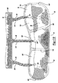
図1および図2を参照すると、履き物10が提示されている。図1を参照すると、履き物10は、アッパー12と、アッパー12に取り付けられているソール構造14とを備えている。履き物10は、1つまたは複数の部分に分割され得る。これらの部分は、前足部16と、中足部18と、かかと部20とを備え得る。前足部16は、つま先と、中足骨を足の趾節骨と接続する関節とに対応するものとしてよい。中足部18は、足の土踏まずと対応するものとしてよく、かかと部20は、踵骨を含む、足の後側部分と対応するものとしてよい。
With reference to FIGS. 1 and 2,
アッパー12は、足を受け入れ、固定してソール構造14上で支持する内部空隙22を画成する内面を備える。かかと部20に配置されているくるぶし開口部24は、内部空隙22へのアクセスを可能にし得る。たとえば、くるぶし開口部24は足を受け入れて足を空隙22内に固定し、内部空隙22からの、および内部空隙22への足の進入および取り出しを円滑にする。いくつかの例において、1つまたは複数のファスナー26がアッパー12に沿って延在し、足の周りで内部空隙22のフィット感を調整し、その際に足の進入および取り出しに同時に応じる。アッパー12は、小穴などの開口28および/またはファスナー26を受け入れる布もしくはメッシュループなどの他の係合特徴部を備え得る。ファスナー26は、レース、ストラップ、コード、フック&ループ、または他の好適な種類のファスナーを含み得る。
The upper 12 includes an inner surface that defines an
アッパー12は、それに加えて、内部空隙22とファスナー26との間に延在するベロ部30を備え得る。アッパー12は、縫い合わせるか、または接着剤で接着されて内部空隙22を形成する1つまたは複数の材料から形成され得る。アッパーに好適な材料は、限定はしないが、織物、発泡体、皮革、および合成皮革を含み得る。材料は、内部空隙22内に配設されている間に足に対して耐久性、通気性、耐摩耗性、柔軟性、および快適性をもたらすように選択され、配置され得る。
The upper 12 may additionally include a
引き続き図1および図2を参照すると、ソール構造14は、ミッドソール32、アウトソール34、および緩衝部材36を備えるものとして図示されている。図2に示されているように、ミッドソール32は、一般的にアウトソール34とアッパー12との間に配設され、緩衝部材36をアッパー12に関して支持する。すなわち、ミッドソール32は、アウトソール34とアッパー12の下側基材38との間で緩衝部材36を支持し得る。基材38は、スティッチング40(図2)を介して、アッパー12に付着され得るか、または代替的に、アッパー12の材料と一体形成され得る。たとえば、アッパー12またはアッパー12の一部がニット材料から形成される場合、ニット材料は、同様に、基材38を形成するものとしてよく、したがって、ミッドソール32および緩衝部材36に対向する基材38は、アッパー12と一体形成され得る。
Continuing with reference to FIGS. 1 and 2, the
基材38がアッパー12から別々に形成される場合、基材38は、スティッチング40を介してアッパー12に付着され得る。基材38がアッパー12と一体形成されるかどうか、または代替的に、アッパー12に付着されている別個の構成要素であるかどうかに関係なく、基材38は、ミッドソール32とアッパー12との間に一般的に配設され、可撓性材料から形成される。基材38を可撓性材料から形成することは、使用中に使用者の足の荷重がかかったときに基材38が伸長し移動することを可能にする。使用中に使用者の足による受ける荷重に応答して基材38が屈曲し、移動することを可能にすることで、使用者の足がミッドソール32および/または緩衝部材36を押圧し、それによって履き物10を使用している使用者にある程度の快適さおよび緩衝作用をもたらすことを可能にするが、これは以下でより詳しく説明される。
If the substrate 38 is formed separately from the upper 12, the substrate 38 can be attached to the upper 12 via the stitching 40. Regardless of whether the substrate 38 is integrally formed with the upper 12 or, instead, is a separate component attached to the upper 12, the substrate 38 is the midsole 32 and the upper 12. Generally disposed between and formed from a flexible material. Forming the substrate 38 from a flexible material allows the substrate 38 to stretch and move when a load on the user's foot is applied during use. The user's foot presses against the midsole 32 and / or the
ミッドソール32は、たとえば、発泡ポリマー材料などのポリマー材料から形成され得る。すなわち、発泡ポリマー材料は、エチル酢酸ビニルまたはポリウレタンであってよい。ミッドソール32の特定の構造に関係なく、ミッドソール32は、一般的にアッパー12の前端部42からアッパー12の後端部44に延在する。さらに、ミッドソール32は、アッパー12の内側46とアッパー12の外側48との間に延在し得る。そうする際に、ミッドソール32の一部は、アッパー12とミッドソール32との接合部の近くのアッパー12の外面50上に延在し得る。たとえば、ミッドソール32は、ミッドソール32の周上に少なくとも部分的に延在し、アッパー12の外面50の一部を覆うようにミッドソール32から延在する突出部52を備え得る。突出部52は、ミッドソールの材料が図2に示されている形状に形成されるときにミッドソール32と一体形成され得る。
The midsole 32 can be formed from a polymeric material such as, for example, a foamed polymeric material. That is, the foamed polymer material may be ethyl vinyl acetate or polyurethane. Regardless of the particular structure of the midsole 32, the midsole 32 generally extends from the
特に図2および図3を参照すると、ミッドソール32は、第1の空洞54と、第2の空洞56と、第3の空洞58とを備えるものとして図示されている。図2および図3に示されているように、空洞54、56、58は、第1の空洞54が前足部16内に配設され、第2の空洞56が中足部18内に配設され、第3の空洞58がかかと部20内に配設されるように、ソール構造14の長さに沿って配設される。空洞54、56、58は、アッパー12の基材38に対向するミッドソール32の第1の表面60内に形成される。第1の表面60は、以下でより詳しく説明されるように、緩衝部材36がミッドソール32内に配設されるときに、ミッドソール32の上面62から陥凹して緩衝部材36の一部に対するクリアランスをもたらす。
In particular, with reference to FIGS. 2 and 3, the midsole 32 is illustrated as having a
ミッドソール32は、それに加えて、ミッドソール32の、第1の表面60とは反対の側に配置されている第2の表面64を備える。第2の表面64は、アウトソール34に対向し、アウトソール34が付着され得る表面を設ける。
The midsole 32 additionally includes a second surface 64 of the midsole 32 that is located on the opposite side of the
空洞54、56、58は、緩衝部材36がミッドソール32内に挿入された後、それぞれ各々ミッドソール32内への緩衝部材36の挿入を許し、緩衝部材36をアウトソール34のところで見えるようにするミッドソール32の第1の開口および第2の開口に関連付けられる。特に、第1の空洞54は、第1の空洞54と第1の表面60との接合部において第1の開口66を画成する。第1の開口66は第1の表面60のところで第1の空洞54への開口部を画成し、一般的に、第1の表面60のところで第1の空洞54の形状を画成する。第1の空洞54は、それに加えて、第1の空洞54の、第1の開口66とは反対の側の端部のところに配設され、第1の空洞54内のミッドソール32の底壁70を通して形成される第2の開口68を備える。一構成において、底壁70および、したがって、第2の開口68は、第1の表面60によって画成される平面に対して実質的に平行である平面内に延在し得る。
The
説明されているように、第1の平面60のところの第1の空洞54への開口部は、一般的に、第1の加工66の形状およびサイズによって画成され、さらに、第1の空洞54の、第1の開口66とは反対の側の端部のところに配設されている第1の空洞54の底部は、一般的に、底壁70によって画成される。第1の空洞54は、底壁70から第1の空洞54の周上の第1の開口66と第1の表面60との接合部まで延在する一連の側面72によってさらに画成される。したがって、側面72は互いに連携して、底壁70と第1の開口66との間を取り巻き、第1の空洞54の形状を画成する。
As described, the opening to the
第2の空洞56は、ソール構造14(図3)の長手方向アクセス部(L)に沿って第1の空洞54と第3の空洞58との間に一般的に配設される。第2の空洞56は、第1の表面60のところで第2の空洞56への開口部を画成する第1の開口74を備える。第2の空洞56は、第2の空洞56の、第1の開口74とは反対の側の端部のところに配設され、ミッドソール32の底壁78を通して形成される第2の開口76をさらに備える。第1の空洞54に関連付けられている底壁70と同様に、第2の空洞56に関連付けられている底壁78は、第2の空洞56の底部を画成し、したがって、第2の空洞56の底面を画成する。側面80は、第1の開口74と底壁78との間に延在し、第2の空洞56の全体的形状を画成する。このように、側面80は底壁78と連携して、第1の開口74と底壁78との間に第2の空洞56の全体的形状を画成する。
The
第3の空洞56は、第1の空洞54および第2の空洞56より後端部44に近い位置に配設され、ミッドソール32の第1の表面60内に形成されている第1の開口82を備える。第1の開口82は第3の空洞58への開口部を画成し、一般的に、第1の表面60のところで第3の空洞58の周の形状を画成する。第3の空洞58は、それに加えて、第3の空洞58の、第1の開口82とは反対の側の端部のところに配設され、ミッドソール32の第3の空洞の底壁86を通して形成される第2の開口84を備える。第1の空洞54および第2の空洞56と同様に、底壁86は、第3の空洞58の、第1の開口82とは反対の側の端部のところに配設され、第3の空洞58の底面を画成する働きをする。側面88は、底壁86から第1の開口82まで延在し、連携して第3の空洞58の周を画成する。
The
説明されているように、第1の空洞54、第2の空洞56、および第3の空洞58の各々は、各空洞54、56、58の形状を画成するそれぞれの側面72、80、88を備える。図3に示されているように、側面72、80、88のうちの1つまたは複数は、それぞれの第1の開口66、74、82からそれぞれの底壁70、78、86への方向に先細りになるものとしてよい。側面72、80、88に、それぞれの第1の開口66、74、82からそれぞれの底壁70、78、86まで延在するテーパーを設けることによって、空洞54、56、58の容積は、ミッドソール32の第1の表面60からミッドソール32の第2の表面64まで延在する方向に一般的に縮小される。図3に示されているように、側面72、80、88が第1の表面62から第2の表面64まで延在する方向に先細りになる程度は、空洞54、56、58の間で異なり得る。たとえば、第1の空洞54は、それぞれ、第2の空洞56および第3の空洞58の側面80、88のうちのいずれかより徐々に先細りになる側面72を備え得る。さらに、第3の空洞58の側面88は、それぞれ、第1の空洞54および第2の空洞56の側面72、80のうちのいずれかより小さいテーパーを備え得る。
As described, each of the
図3を特に参照すると、第1の空洞54、第2の空洞56、および第3の空洞58は、ソール構造14の長手方向アクセス部(L)に沿って相隔てて並ぶ配置でミッドソール32の材料内に形成されるものとして図示されている。したがって、ミッドソール32の第1の壁90は、第1の空洞54と第2の空洞56との間に延在するものとしてよく、第2の壁92は第2の空洞56と第3の空洞58との間に延在し得る。したがって、第1の壁90は第1の空洞54を第2の空洞56から分離する働きをし得るが、第2の壁92はソール構造14の長手方向アクセス部(L)に沿って延在する方向で第2の空洞56を第3の空洞58から分離する働きをする。以下でより詳しく説明されるように、壁90、92は、ミッドソール32に関する緩衝部材36の所望の位置を維持するのを助け、したがって、履き物10の使用時に所望の緩衝作用を使用者の足にもたらすのを助ける。
With particular reference to FIG. 3, the
特に図2および図3を参照すると、緩衝部材36は、第1の障壁部材94と、第2の障壁部材96と、緩衝部材36内に収容される一定量の粒子状物質98とを備えるものとして図示されている。一構成において、第2の障壁部材96は第1の障壁部材94に付着され、粒子状物質98を一般的に第2の障壁部材96と第1の障壁部材94との間に収容する。たとえば、緩衝部材36は、第1の区画100と、第2の区画102と、第3の区画104とを備えるものとしてよく、各々第1の量の粒子状物質98と、第2の量の粒子状物質98と、第3の量の粒子状物質98とをそれぞれ組み込む。
In particular, referring to FIGS. 2 and 3, the cushioning
第1の障壁部材94および第2の障壁部材96は、ソール構造14が使用者の足から力を受けるときに第1の障壁部材94および第2の障壁部材96が履き物10の使用中に伸長し、移動することを可能にする可撓性材料から形成され得る。一構成において、第1の障壁部材94および第2の障壁部材96は、異なる材料から形成される。たとえば、第1の障壁部材94は、熱可塑性ポリウレタン(TPU)などのポリマー材料から形成され得る。第1の障壁部材94をTPUから形成することは、第1の障壁部材94が不浸透性材料から形成されることを可能にし、いくつかの構成において、第1の障壁部材94が光学的に透明および/または半透明の材料から形成されることを可能にする。
In the
第2の障壁部材96は、たとえば、スパンデックスなどの、可撓性材料から形成され得る。第2の障壁部材96をスパンデックスなどの可撓性材料から形成することは、第2の障壁部材96が浸透性であることを可能にもする。第2の障壁部材96を浸透性材料から形成することは、第2の障壁部材96を通して第1の区画100、第2の区画102、および第3の区画104内に流体的に連通することを許し、それによって緩衝部材36の外部にある領域から区画100、102、104内への空気循環を許す。
The
第2の障壁部材96は、接着剤106を介して第1の障壁部材94に付着されるものとしてよい。接着剤106はホットメルト接着剤であってよく、第1の区画100、第2の区画102、および第3の区画104の各々の周を囲み得る。したがって、接着剤106は区画100、102、104の各々の間で第2の障壁部材96の材料を第1の障壁部材94の材料に結合し、それによって、第2の障壁部材96と第1の障壁部材94との間の各区画100、102、104内に内部空隙を画成する。
The
接着剤106が各区画100、102、104を完全に囲むように各区画100、102、104の周上で第2の障壁部材96を第1の障壁部材94に付着させることで、第2の障壁部材96が第1の障壁部材94に付着される領域内にウェブ部材108を形成する。ウェブ部材108は、図9に示されているように、各区画100、102、104の間、さらには緩衝部材36の外周上に延在し得る。ウェブ部材108は、ミッドソール32の上面62に関してミッドソール32の第1の表面60の深さに実質的に等しい厚さを備え得る。さらに、緩衝部材36の周のところでウェブ部材108によって画成されるような緩衝部材36の全体的な形状は、上面62内に形成されたときに、第1の表面60の形状に実質的に等しい形状を備え得る。したがって、緩衝部材36がミッドソール内に挿入されたときに、緩衝部材36の上面110はミッドソール32の上面62と実質的に同一平面上にあり、それによって、基材38を受け入れる均一な表面をもたらす。基材38に対向する均一な表面をもたらすことで、使用者がミッドソール32と緩衝部材36との間の移行または接合を感じることを防ぐことによって使用者の足に対する一定の度合いの快適さをもたらす。
A
特に図3を参照すると、緩衝部材36は、区画100、102、104内に配設される様々な量の粒子状物質98を含むものとして示されている。たとえば、第1の区画100、第2の区画102、および第3の区画104は、各々、異なる量の粒子状物質98を備えるものとして示されている。すなわち、第1の空洞54およびしたがってソール構造14の前足部16とともに配設されている第1の区画100は、第2の区画102および第3の区画104より少ない粒子状物質98を備える。逆に、ミッドソール32の第3の空洞58によって受け入れられ、およびしたがってソール構造14のかかと部20内に配置されている第3の区画104は、第2の区画102および第1の区画100より多い量の粒子状物質98を受け入れる。区画100、102、104は、異なる量の粒子状物質98を受け入れるものとして説明され、図示されているが、各区画100、102、104は、おおよそ同じ量の粒子状物質98を受け入れるものとしてよい。さらに、区画100、102、104のうちの1つまたは複数は、緩衝部材36(図9)の外面110内に出っ張り112を形成する多量の粒子状物質98を受け入れるものとしてよい。たとえば、緩衝部材36の第2の区画102および第3の区画104は、各々、第2の区画102および第3の区画104の位置で第2の障壁部材96によって画成される公称平面から延在する出っ張り112を備え得る。すなわち、出っ張り部112は、ウェブ部材108によって画成される公称平面から延在する。
In particular, with reference to FIG. 3, the
それぞれの区画100、102、104内に配設される粒子状物質98の量に関係なく、粒子状物質98は、ミッドソール32の材料がもたらす機能性および緩衝特性を増強するために使用され得る。たとえば、区画100、102、104内に収容される粒子状物質98は、実質的に球状の形状を有する発泡ビーズを含み得る。さらに、粒子状物質98を画成する発泡ビーズは、おおよそ同じサイズおよび形状を有し得るか、または代替的に、異なるサイズおよび形状のうちの少なくとも1つを有し得る。粒子状物質98の特定のサイズおよび形状に関係なく、粒子状物質98はアウトソール34およびミッドソール32と連携して、使用中に履き物10に緩衝および応答性能を付与する。
Regardless of the amount of
緩衝部材36は、第1の区画100が第1の空洞54によって受け入れられ、第2の区画102が第2の空洞56によって受け入れられ、第3の区画104が第3の空洞58によって受け入れられるようにミッドソール32内に挿入され得る。緩衝部材36がミッドソール32内に配設されると、緩衝部材36の面110は緩衝部材36の周を画成するウェブ部材108のところでミッドソール32の上面62と実質的に同一平面上にある。したがって、第2の障壁部材96は、ミッドソール32の上面62のところでミッドソール32の材料と連携し、ソール構造14がアッパー12に付着されたときに基材38が当たって留まる一般的に均一な表面をもたらす。
The cushioning
アウトソール34は、透明または半透明材料から形成されるものとしてよく、互いに分離している1つまたは複数の離散部分を備え得る。アウトソール34は、たとえばゴムなどの耐久性のある材料から形成されてよく、ミッドソール32の第2の表面64に付着され得る。アウトソール34の個別の部分は、第1の空洞54、第2の空洞56、および第3の空洞58にそれぞれ関連付けられている第2の開口68、76、84に近いミッドソール32の第2の表面64に付着され得る。アウトソール34のそれらの部分は、長手方向軸(L)に実質的に平行な方向でソール構造14の長さに沿って互いから分離され得る。アウトソール34は互いに相隔てて並ぶ個別の部分を含むものとして記載され示されているが、アウトソール34は、代替的に、アウトソール34が前端部42と後端部44との間および内側46と外側48との間に連続的に延在するようにミッドソール32の第2の表面64全体にわたって一般的に延在する一体構造を有することが可能である。アウトソール34の特定の構造(すなわち、一体部分または離散部分)に関係なく、アウトソール34は、アウトソール34から延在し履き物10の使用時に地面との間のトラクションを高めるトレッド35を備え得る。
The
アウトソール34を透明または半透明材料から形成することで、アウトソール34がミッドソール32に第2の表面64のところで付着されたときに空洞54、56、58がアウトソール34から見えるようにすることができる。さらに、区画100、102、104は、ミッドソール32のそれぞれの空洞54、56、58を実質的に満たすので、区画100、102、104およびしたがってその中に配設される粒子状物質98は、同様に、アウトソール34の材料を通してミッドソール32の第2の開口68、76、84のところから見える。したがって、緩衝部材36のそれぞれの区画100、102、104内に置かれる粒子状物質98は、アウトソール34を通して、それぞれの空洞54、56、58に関連付けられている第2の開口68、76、84のところから見える。
By forming the
ソール構造14は、好適な接着剤114(図3)を介してアッパー12に付着され得る。たとえば、接着剤114は、ミッドソール32の突出部52とアッパー12の外面50との間に延在し、それらを付着させ得る。さらに、接着剤114は、緩衝部材36のウェブ部材108をミッドソール32に、ウェブ部材108とミッドソール32の第1の表面60との接合部のところで付着させ得る。
The
緩衝部材36を履き物10に組み込むことで、使用中に使用者の足に対してある程度の快適さと緩衝作用をもたらす。たとえば、上で説明されているように、基材38、および緩衝部材36の第2の障壁部材96は、可撓性材料から形成される。したがって、履き物の使用中に力が使用者の足によって基材38に加えられたときに、この力は、基材38および第2の障壁部材96の材料の屈曲および伸長を引き起こし、それによって、使用者の足が区画100、102、104内に配設されている粒子状物質98と係合し、変位させることを可能にする。そうする際に、粒子状物質98は、第1の障壁部材94の材料に力を加え、それによって、第1の障壁部材94を同様に屈曲させ伸長させる。第1の障壁部材94のそのような移動は、区画100、102、104を一般的に囲むミッドソール32の材料を圧縮し、延いては歩くまたは走る動作に関連付けられている力を吸収する。
Incorporating the
基材38、第1の障壁部材94、および第2の障壁部材96の材料を、ミッドソール32の材料を圧縮するとともに屈曲させ伸長させることで、履き物10を履いている状態で使用者にある程度の緩衝作用および快適さをもたらす。さらに、使用者の足と粒子状物質98との間の相互作用−基材38および第2の障壁部材96の材料の一般的に曲げやすい性質によって許される−は、同様に、使用者の足に緩衝作用をもたらす。さらに、粒子状物質98は各区画100、102、104に関して、またその中で移動することを許されるので、粒子状物質98は使用者の足の形状に適合し、したがって使用者の足の形状に特有のある程度の修正された緩衝作用をもたらす。なおもさらに、粒子状物質98は第1の区画100、第2の区画102、および第3の区画104に関して、またその中で移動することを許されるので、基材38および第2の障壁部材96の形状は動的であり、もっぱら、任意の時点における基材38に加えられる荷重に基づく。言い換えると、区画100、102、104内に配設されている粒子状物質98によってもたらされる支持は、基材38のところに加えられた力に応答して移動しシフトする。そうする際に、基材38および第2の障壁部材96の効果的な形状は、使用者が力を基材38の異なる位置に加えるときに常時変化しており、それによって、粒子状物質98を区画100、102、104の内部に対してシフトし、移動することを引き起こす。したがって、緩衝部材36は、ソール構造14およびしたがって履き物10に、緩衝、および加えられた力に動的に応答し、使用者の足の形状に自動的に適合する支持をもたらし、それによって、使用者に手直しされた個人的緩衝システムを提供する。
By compressing and bending and stretching the material of the base material 38, the
図4〜図9を特に参照して、緩衝部材36を作製する方法が詳しく説明される。以下で詳しく説明されるように、図4〜図7に示されている緩衝部材36を形成する方法は、熱成形プロセスを使用して第1の緩衝部材94を形成し、さらに、粒子状物質98を第1の区画100、第2の区画102、および第3の区画104に挿入した後、熱プレスを使用して第2の障壁部材96を第1の障壁部材94に付着させる。
A method of making the cushioning
図4に示されているように、材料202のシートを第1の障壁部材94内に形成するために工具200が使用されるものとしてよい。たとえば、上で説明されているように、第1の障壁部材94は、熱可塑性ポリウレタン(TPU)から形成され得る。したがって、材料202のシートは、TPU材料のシートであってよい。工具200は、第1の空洞204、第2の空洞206、および第3の空洞208を備え得る。第1の空洞204は、第1の区画100に図5に示されている形状をもたらすアーチ形表面210を備え得る。同様に、第2の空洞206は第2の区画102と対応するものとしてよく、第3の空洞208は第3の区画104と対応するものとしてよく、それによって、第2の空洞206は第2の区画102の形状に適合するアーチ形表面212を備え、第3の空洞208は第3の区画104の形状に適合するアーチ形表面214を備える。工具200は、それに加えて、バキューム218(図5)に付着されている一連のバキュームポート216を備え得る。
As shown in FIG. 4, the
動作時に、材料202のシートは、材料202のシートが第1の空洞204、第2の空洞206、および第3の空洞208に対向するように工具200に隣接して置かれるものとしてよい。バキュームポート216を介して材料202のシート上に真空力を加える前および/または加えているときに材料202のシートに熱が加えられ得る。たとえば、材料202のシートは、外部熱源(図示せず)によって、および/または工具200内に配設されている加熱素子(図示せず)を介して加熱され、それにより材料202のシートを、材料202のシートがバキューム218およびバキュームポート216を介して空洞204、206、208内に引き込まれるのと同時に加熱するものとしてよい。
During operation, the sheet of material 202 may be placed adjacent to the
図5に示されているように、材料202が空洞204、206、208内に引き込まれるように材料202のシートを形成することで、緩衝部材36のそれぞれの区画100、102、104を形成する。特に、材料202のシートの材料はアーチ形表面210、212、214と係合し、材料202のシートを緩衝部材36の様々な区画100、102、104内に形成する。材料202のシートに加えられる熱および圧力(すなわち、バキューム(218)ならびに内部熱源および/または外部熱源によって)は、材料202のシートを空洞204、206、208のところで工具200の形状に一般的に適合させ、それによって緩衝部材36の第1の障壁部材94を形成する。材料202のシートが第1の障壁部材94の形状に形成された後、第1の障壁部材94の材料は冷まされ、それによって、空洞206、208、210のアーチ形表面210、212、214によってそれぞれ画成されるように、第1の障壁部材94の材料に工具200の形状を保持させる。
As shown in FIG. 5, by forming a sheet of material 202 such that material 202 is drawn into
材料202のシートが、上で説明されているように、第1の障壁部材94の形状に形成された後、区画100、102、104は粒子状物質98を充填され得る。上で説明されているように、粒子状物質98は、同じおよび/または異なる形状を有する発泡ビーズを含むものとしてよく、緩衝部材36に、第2の障壁部材96が第1の障壁部材94に付着され、緩衝部材36がミッドソール32内に挿入された後に履き物10に対する緩衝作用をもたらす能力を付与する。
After the sheet of material 202 is formed in the shape of the
粒子状物質98は、一連のホッパー(図6)を介して粒子状物質98を各区画100、102、104内に堆積させることによって区画100、102、104内に挿入され得る。特に、第1のホッパー220は第1の区画100と位置合わせされ、第2のホッパー222は第2の区画102と位置合わせされ、第3のホッパー224は第3の区画104と位置合わせされるものとしてよく、これにより、ホッパー220、222、224が粒子状物質98を放出したときに、粒子状物質98は、それぞれの区画100、102、104によって受け入れられる。一構成において、ホッパー220、222、224は、それぞれのホッパー220、222、224に関連付けられている弁または他の計量デバイス(いずれも図示されていない)が開いているときに、ホッパー220、222、224内に配設されている粒子状物質98がホッパー220、222、224から自動的に分注され、第1の障壁部材94の区画100、102、104によって受け入れられるように重力で供給され得る。所定の量の粒子状物質98が第1の区画100、第2の区画102、および第3の区画104によって受け入れられた後、ホッパー220、222、224に関連付けられている弁は、さらなる粒子状物質98が区画100、102、104のうちのいずれかによって受け入れられるのを防ぐように閉じられ得る。
特に図7を参照すると、区画100、102、104は、粒子状物質98を実質的に充填されているものとして図示されている。この時点で、接着剤106は、区画100、102、104を囲む領域に塗られ、第1の障壁部材94が第2の障壁部材96に付着されることを可能にし得る。上で説明されているように、一構成において、接着剤106はホットメルト接着剤であってよい。ホットメルト接着剤は、区画100、102、104を囲む領域および工具200の隆起部226のところで第1の障壁部材94に付けられるものとしてよい。図3に示されているように、隆起部226は、一般的に、ミッドソール32の第1の壁90および第2の壁92の形状をまねて、緩衝部材36がミッドソール32の空洞54、56、58によって受け入れられ嵌合することを可能にし得る。
In particular, with reference to FIG. 7, compartments 100, 102, 104 are illustrated as being substantially filled with
接着剤106が第1の区画100、第2の区画102、および第3の区画104を囲む領域内で第1の障壁部材94上に配設された後、材料228のシートが第1の障壁部材94と熱源230との間に置かれるものとしてよい。材料228のシートは、材料228のシートが第1の区画100、第2の区画102、および第3の区画104に対向し覆うように接着剤106上に位置決めされ得る。材料228のシートが第1の障壁部材94に関して適切に置かれた後、熱源230が活性化され、それによって、接着剤が材料228のシートと接着し、第1の区画100、第2の区画102、および第3の区画104を封止することを行わせるものとしてよい。
After the adhesive 106 is disposed on the
材料228のシートが第1の障壁部材94に付着された後、材料228のシートは、第1の区画100、第2の区画102、および第3の区画104を閉鎖し、それにより、第2の障壁部材96を形成する。図8に示されているように、第2の障壁部材96は、上で説明されているように、それぞれの区画100、102、104内に配設されている粒子状物質98の量に応じて出っ張り112を画成し得る。それぞれの区画100、102、104によって受け入れられる粒子状物質98の量に関係なく、材料228のシートが第1の障壁部材94に付着され、したがって第2の障壁部材96を形成した後、緩衝部材36は、第1の区画100がミッドソール32の第1の空洞54によって受け入れられ、第2の区画102がミッドソール32の第2の空洞56によって受け入れられ、第3の区画104がミッドソール32の第3の空洞58によって受け入れられるようにミッドソール32内に挿入され得る。
After the sheet of
上で説明されているように、緩衝部材36は熱成形プロセスを介して形成され得る。そうする際に、第1の区画100、第2の区画102、および第3の区画104は、所定の量の粒子状物質98を受け入れ、さらに、その結果、履き物10に取り付けられた後基材38に対向する外面110のところに第2の障壁部材96が出っ張り112を形成し得る。その量の粒子状物質98が第1の区画100、第2の区画102、および/または第3の区画104内に配設された結果、1つまたは複数の出っ張り112が第2の障壁部材96のところに形成され得るが、出っ張り112は、第1の障壁部材94の縁の上に粒子状物質98をこぼすことなくホッパー220、222、224を介して様々な区画100、102、104内に堆積され得るものに制限される。したがって、出っ張り112が緩衝部材36から延在する程度は、粒子状物質98が第1の障壁部材94の縁の上にこぼれることなく区画100、102、104内に積層され得る粒子状物質98の量に制限される。
As described above, the
出っ張り112は、第2の障壁部材96を第1の障壁部材94に最初に付着させることによって大きくすることが可能であり、それによって粒子状物質98が区画100、102、104内に挿入される前に区画100、102、104を閉じる。第2の障壁部材96が第1の障壁部材94に付着された後に粒子状物質98を区画100、102、104内に挿入するのに、上で説明されている熱成形プロセスと異なるプロセスを使用することが必要になる。
The
以下でより詳しく説明されるように、圧縮成形プロセスは、粒子状物質98を区画100、102、104内に挿入する前に最初に第2の障壁部材96を第1の障壁部材94に結合しようとして熱成形プロセスの代わりに使用することも可能である。区画100、102、104に粒子状物質98を充填する前に第2の障壁部材96を第1の障壁部材94に最初に付着させることで、緩衝部材36が上で説明され図4〜図7に示されている熱成形プロセスを介して形成されるときに区画100、102、104のうちの1つまたは複数が区画100、102、104内に挿入できる粒子状物質98の量に関して粒子状物質98を過剰充填され得る。
As described in more detail below, the compression forming process will first couple the
図10〜図20を参照して、緩衝部材36を作製する際に使用するための圧縮成形プロセスが詳しく説明される。
The compression molding process for use in making the cushioning
圧縮成形プロセスは、鋳型上半分302と鋳型下半分304とを含む鋳型300を利用し得る。鋳型下半分304は、第1の空洞308、第2の空洞310、および第3の空洞312を備え得る。第1の空洞308は、第1の障壁部材94の第1の区画100を形成するために使用されるアーチ形表面314を備え得る。同様に、第2の空洞310は、第1の障壁部材94の第2の区画102を形成するために使用されるアーチ形表面316を備え得、第3の空洞312は、第1の障壁部材94の第3の区画104を形成するために使用されるアーチ形表面318を備え得る。空洞308、310、312および関連付けられているアーチ形表面314、316、318は、図4〜図7に示されている熱成形プロセスを介して第1の障壁部材94を形成するために使用される工具200の、それぞれ、空洞204、206、208およびアーチ形表面210、212、214と同一であってよい。
The compression molding process may utilize a
鋳型上半分302は、それぞれの空洞308、310、312内に貫入する突出部を備え得る。特に、鋳型上半分302は、第1の空洞308、第2の空洞310、および第3の空洞312によってそれぞれ受け入れられる第1の突出部320、第2の突出部322、および第3の突出部324を備えるものとしてよい。突出部320、322、324は、以下でより詳しく説明されるように、それぞれのアーチ形表面314、316、318の形状をまね、第1の障壁部材94を形成するために使用されるTPU材料のシートの厚さだけアーチ形表面314、316、318から間隔をあけて並ぶものとしてよい。
The
動作時に、TPU材料のシートなどの材料306のシートは、鋳型上半分302と鋳型下半分304との間に挿入され得る。材料306のシートは、鋳型下半分304から、材料306のシートの一部を通って延在する一対の支柱326を介して鋳型下半分304に付着され得る。
During operation, a sheet of
材料306のシートが鋳型上半分302と鋳型下半分304(図10)との間に配設された後、鋳型の各半分302、304は互いの方へ近づけられ得るか、または代替的に、鋳型の各半分302、304のうちの一方が鋳型の各半分302、304のうちの他方の方へ、鋳型の各半分302、304が図11に示されている位置に移動されるまで移動され得る。すなわち、鋳型上半分302および/または鋳型下半分304は、図10に示されている位置から図11に示されている位置まで移動され、材料306のシートを実質的に平面状の形状(図10)から第1の障壁部材94の形状(図11)に形成するものとしてよい。鋳型の各半分302、304が図11に示されている構成において位置決めされたときに、支柱326は、鋳型上半分302のそれぞれの開口328内に受け入れられるものとしてよく、それによって、鋳型上半分302と鋳型下半分304との間に相対的間隔を画成する。一構成において、この間隔は、突出部320、322、324と空洞308、310、312のそれぞれのアーチ形表面314、316、318との間の材料306のシートの圧縮を防ぐために材料306のシートの厚さにおおよそ等しい。
After a sheet of
材料306のシートを支柱326と係合させることで、支柱326のところの材料306のシートの位置を鋳型下半分304に関して維持する。したがって、鋳型上半分302が突出部320、322、324のところで材料306のシートと係合するときに、材料306のシートの材料は伸長され、アーチ形表面314、316、318によって画成される形状に形成される。鋳型上半分302による材料306のシートが変形することで、材料306のシートを図12に示されている形状に形成する。
By engaging the sheet of
図12に示されているように、材料306のシートは、区画100、102、104を画成する形状に形成されるが、支柱326が図9に示されている第1の障壁部材94の形状に関して材料306のシートと係合する位置に追加の材料を含む。したがって、図12に示されている材料306のシートは、部分的に形成された第1の障壁部材94である。追加の材料は、材料306のシートの周上に一般的に延在し、鋳型300によって形成される区画100、102、104を囲むフランジ330を画成する。フランジ330は、それに加えて、材料306のシートを図12に示されている構成に形成するときに支柱326によって形成される一対の開口332を備え得る。以下でより詳しく説明されるように、開口332を伴うフランジは材料306のシートから取り除かれ、たとえば、打ち抜きプロセスを介して第1の障壁部材94を形成し得る。
As shown in FIG. 12, the sheet of
材料306のシートが図12に示されている構成に形成された後、第2の障壁部材96を形成するために使用される材料334のシートは、材料306のシートに付着され得る。上で説明されているように、第2の障壁部材96は、スパンデックスなどの、可撓性材料から形成され得る。さらに、第2の障壁部材96は、接着剤106を介して第1の障壁部材94に付着されるものとして説明されている。図13に示されているように、接着剤106は、たとえば、ホットメルト接着剤のシートなどの接着材336のシートの形態で提供され得る。最後に、ブロッキング要素338が接着剤106と第1の障壁部材94を形成する材料306のシートとの間に位置決めされ、接着剤106と結合されていない第1の障壁部材94との間に領域を形成し得る。接着剤106と結合されていない第1の障壁部材94との間に領域を形成することでも、同様に、第1の障壁部材94と結合されていない第2の障壁部材96との間に領域を形成する。以下でより詳しく説明されるように、第1の障壁部材94がブロッキング要素338を介して第2の障壁部材96から分離される領域は、粒子状物質98が第1の区画100、第2の区画102、および第3の区画104内に挿入されることを許される領域をもたらす。
After the sheet of
材料306のシートは、材料306のシートが図12に示されている構成に形成された後に第1の材料306の形状に一般的に適合する工具340(図14)内に置かれるものとしてよい。工具340は、熱成形プロセスに関して上で説明されている工具200と同一であるものとしてよい。代替的に、工具340は、工具340が工具200に関連付けられているバキュームポート216を備えることができないという点を除き工具200と同一であってよい。工具340の特定の構成に関係なく、工具340は、鋳型300による形成の後に材料306のシートによって画成される第1の区画100、第2の区画102、および第3の区画104をそれぞれ受け入れる第1の空洞342、第2の空洞344、および第3の空洞346を備え得る。
The sheet of
材料306のシートが、第1の区画100が第1の空洞342によって受け入れられ、第2の区画102が第2の空洞344によって受け入れられ、第3の区画104が第3の空洞346によって受け入れられるように工具340内に挿入された後、ブロッキング要素338は材料306のシートの上に位置決めされ、接着材336のシートはブロッキング要素338上に置かれ、第2の障壁部材96を形成する材料334のシートは接着剤336のシートの上部に置かれるものとしてよい。したがって、ブロッキング要素338は、接着剤336のシートと、第1の障壁部材94を形成する材料306のシートとの間に配設され、接着剤336のシートは、第2の障壁部材96を形成する材料334のシートと、ブロッキング要素338との間に配設され、第2の障壁部材96を形成する材料334のシートは接着材336のシート上に配設され、露出されている外面348を備える。
The sheet of
特に図13を参照すると、接着剤のシートは、第1の開口350と、第2の開口352と、第3の開口354とを備えるものとして図示されている。第1の開口350は、第1の区画100の形状に対応する形状を備え、接着剤106が第1の区画100を完全に囲むことを可能にする。同様に、第2の開口352は、第2の区画102の形状に対応する形状を備え、接着材336のシートの接着剤106が第2の区画102を完全に囲むことを可能にするが、第3の開口354は、第3の区画104の形状に対応する形状を備え、接着材336のシートの接着剤106が第3の区画104を完全に囲むことを可能にする。
In particular, with reference to FIG. 13, the adhesive sheet is illustrated as having a
接着材336のシートは、それに加えて、第4の開口356、第5の開口358、および第6の開口360を備える。第4の開口356、第5の開口358、および第6の開口360は、追加の緩衝部材36の第1の障壁部材94の第1の区画100、第2の区画102、および第3の区画104にそれぞれ対応し得る。たとえば、接着材336のシートは、一対の緩衝部材36を同時に形成するために使用され得る。図13に示されているように、接着材336のシートおよび関係する開口350、352、354、356、358、360は、異なる履き物10とともに使用するために緩衝部材36に適応するようにサイズおよび位置を決められる。すなわち、開口350、352、354は、右足の履き物10とともに使用する緩衝部材36を形成するために使用されるが、開口356、358、360は、左足の履き物10とともに使用する緩衝部材36を形成するために使用される。接着材336のシートおよび関係する開口350〜360は、右足の履き物10とともに使用する緩衝部材36と、左足の履き物10とともに使用する緩衝部材36とを形成するために使用されるものとしてそれぞれ説明され図示されているが、開口350〜360は、接着材336のシートを通して形成され、同じ構成を有する一対の緩衝部材36が形成されるように位置決めされることも可能であろう。すなわち、一対の緩衝部材36は、右足の履き物10とともに使用するように形成されるか、または代替的に、一対の緩衝部材36は、左足の履き物10とともに使用するように形成されることが可能である。
The sheet of adhesive 336 further comprises a
最後に、一対の緩衝部材36は、接着材336のシートを介して同時に形成されるものとして説明されているが、接着材336のシートは、ただ1つの緩衝部材36が形成されるように全部で3つの開口のみを備えることも可能である。すなわち、接着材336のシートは、右足の履き物10用に緩衝部材36を作製する際に使用するための開口350、352、354を備えるか、または代替的に、左足の履き物10とともに使用する緩衝部材36を作製する際に使用するための開口356、358、360のみを備えることも可能である。接着材336のシートは、同じもしくは異なる側の足の履き物用に一対の緩衝部材36を形成するために使用されるか、または代替的に、単一の緩衝部材36を作製するように構成されることも可能であるが、接着材336のシートは、これ以降、右足の履き物10および左足の履き物10において使用するようにそれぞれ構成される一対の緩衝部材36を形成するために使用される6個の開口350〜360を備えるものとして説明され図示される。
Finally, the pair of
特には図示されていないが、工具340は、材料306の同じシートまたは材料306の個別のシートの一部をそれぞれ受け入れる2組の空洞342、344、346を備え、接着材336のシートの開口に関して区画100、102、104を位置決めすることも可能である。このようにして、工具340は、接着材336のシートに関して材料306の同じもしくは異なるシートの一対の第1の区画100、一対の第2の区画102、および一対の第3の区画104を支持し、接着剤106を介してそれらの対の区画100、102、104を材料334のシートに同時に結合することも可能である。
Although not specifically shown, the
ブロッキング要素338は、接着材336のシートの接着剤106に接着することに抵抗する材料から形成され得る。たとえば、ブロッキング要素338は、接着材336のシートの接着剤106と第1の障壁部材94を形成する材料306のシートとの間の接着を阻害するKevlar(登録商標)から形成されてよい。
The blocking
ブロッキング要素338を形成するために使用される材料に関係なく、ブロッキング要素338は、本体部364から延在する一連の突出部362を備え得る。突出部362は、各突出部362が接着材336のシートのそれぞれの開口350〜360と位置合わせされるように本体部364の長さに沿って配設され得る。
Regardless of the material used to form the blocking
説明されているように、接着材336のシートは、開口350〜360が材料306の1つまたは複数のシートによって形成されるそれぞれの区画100、102、104と位置合わせされるように位置決めされ、それにより一対の緩衝部材36を同時に形成する。したがって、突出部362と開口350〜360との位置合わせを、1つの突出部362がそれぞれの開口350〜360の各々と位置合わせされるように行うことでも、同様に、突出部362を、一対の緩衝部材36を形成するために使用される一対の第1の障壁部材94の区画100、102、104と位置合わせする。したがって、ブロッキング要素338が接着材336のシートと第1の障壁部材94を形成する材料306のシートとの間に配設されたときに、ブロッキング要素338は、突出部362が各障壁部材94の区画100、102、104とそれぞれ位置合わせされるように位置決めされる。
As described, the sheets of adhesive 336 are positioned so that the openings 350-360 are aligned with the
ブロッキング要素338、接着材336のシート、および第2の障壁部材96を形成する材料334のシートが第1の障壁部材94を形成する材料306のシート上に積層された後、熱を表面348に加えるために加熱デバイス366が使用され得る。第2の障壁部材96を形成する材料334のシートを加熱することで、接着材336のシートの接着剤106を活性化し、それによって第2の障壁部材96を形成する材料334のシートを、ブロッキング要素338の配置を除くすべての配置で、第1の障壁部材94を形成する材料306のシートに接着する。すなわち、接着材336のシートは、突出部362およびブロッキング要素338の本体部364の位置で第1の障壁部材94を形成する材料306のシートに接着されない。
After the
第2の障壁部材96を形成する材料334のシートが第1の障壁部材94を形成する材料306のシートに付着された後、アセンブリは図15に示されている構成を含む。この時点では、第2の障壁部材96を形成する材料334のシートは、第1の障壁部材94を形成する材料306のシートに付着されるが、粒子状物質98を含まない。したがって、図15に示されている構成は、粒子状物質98を欠いている事前充填された障壁部材である。
After the sheet of
図13に関して上で説明されているように、接着材336のシートおよびブロッキング要素338は、一対の緩衝部材36を形成するために使用される。図16に示されているように、一対の緩衝部材36は、互いに分離され、一対の第2の障壁部材96を形成する材料334のシートおよび第1の障壁部材94を形成する材料306のシートを打ち抜きプロセスに通すことによって図9に関して上で図示されている緩衝部材36の形状に形成され得る。すなわち、材料306、334の結合されたシートは、上側金型370と下側金型372とを有する打ち抜き工具368内に挿入され得る。特に、図15に示されている構成は、下側鋳型372の空洞374内に挿入され、上側金型370に関連付けられている切断機構376に関して材料306、334の結合されたシートを適切に位置決めし得る。特に例示されてはいないが、切断機構376は、図9に示されている緩衝部材36の外周を画成する形状を含む。さらに、図15の断面図では切断機構376が1つのみ図示されているが、一対の緩衝部材36が材料306、334の結合されたシートから同時に切断されている場合には、一対の切断機構376が使用されることも可能である。
As described above with respect to FIG. 13, the sheet of adhesive 336 and the blocking
動作時に、上側金型370および、したがって、切断機構376は下側金型372の方へ平行移動し、切断機構376は材料306、334の結合されたシートの外周と係合し、それによって事前充填された緩衝部材36を互いに分離させ、事前充填された緩衝部材36を図9に示されている形状に形成する。この時点において、一対の事前充填された緩衝部材36は互いに分離され、所定の量の粒子状物質98を充填され得る。
During operation, the
特に図17〜図19を参照すると、区画100、102、104は、区画100、102、104に関連付けられているそれぞれのポート380のところで注入ノズル378を受け入れるものとして図示されている。ポート380は、ブロッキング要素338の突出部362の位置に形成される。すなわち、上で説明されているように、突出部362は、接着材336のシートの接着材106が第2の障壁部材96を突出部362の位置で第1の障壁部材94に結合することを妨げる。したがって、ポート380は、ブロッキング要素338の突出部362の位置に形成され、それによって、ノズル378がそれぞれの区画100、102、104内に挿入されることを可能にする。
In particular, with reference to FIGS. 17-19,
動作時に、ノズル378は、区画100、102、104のそれぞれのポート380内に挿入され、区画100、102、104の内部と流体的に連通する。図17〜図19に示されている図は部分的切欠図であり、それにより、第2の障壁部材96の一部は、第1の障壁部材94の第1の区画100、第2の区画102、および第3の区画104が見えるように取り除かれている。
During operation, the
ノズル378が、ノズル378が第2の障壁部材96と第1の障壁部材94との間に配設されるようにポート380内に配設された後、粒子状物質98が流体圧力を介してノズル378内に挿入され得る。たとえば、空気圧は、ホッパー382(図18)内に配設されている粒子状物質98をノズル378内に導くために使用され得る。ノズル378は、共通のホッパー382に関連付けられているものとして説明され図示されているが、ノズル378は、代替的に、粒子状物質98をノズル378に供給する個別のホッパーに関連付けられることも可能である。
After the
図17〜図19に示されているように、ノズル378は、粒子状物質98の外径に実質的に等しい内径を備え得るか、または代替的に粒子状物質98の外径よりわずかに大きく、ノズル378内の粒子状物質98が瘤状になり詰まることを防ぐ。粒子状物質98は、ノズル378を介して区画100、102、104内に注入されるものとしてよく、さらに、粒子状物質98は空気圧などの流体圧力の下で注入されるので、区画100、102、104内に配設される粒子状物質98は、区画100、102、104のうちの1つまたは複数を過剰充填し得る。したがって、区画100、102、104は、図4〜図7の熱成形プロセスに関して上で説明されているように、区画100、102、104が粒子状物質98を充填されたときに区画100、102、104内に入れられた粒子状物質の量に比べて大量の粒子状物質98を備え得る。すなわち、粒子状物質98は流体圧力の下で区画100、102、104内に注入されるので、さらに、第2の障壁部材96は第1の障壁部材94に付着され、各障壁部材94、96は可撓性材料から形成されるので、粒子状物質98は区画100、102、104の各々の中で過剰充填され、それによって結果として、区画100、102、104のうちの1つまたは複数のところでより大きい出っ張り112を生じ得る。出っ張りは、図21および図22に第2の障壁部材96の表面から延在するように図示されている。
As shown in FIGS. 17-19, the
所望の量の粒子状物質が各区画100、102、104内に配設された後、ポート380は、ポート380のところで第1の障壁部材94と第2の障壁部材96とを結合することによって閉じられるものとしてよい。たとえば、第1の障壁部材94および第2の障壁部材96は、各ポート位置で高周波(RF)溶接などの溶接プロセスに局所的に通され得る。図20に示されているように、1つまたは複数の溶接装置384は、ポート380のその位置で第1の障壁部材94と第2の障壁部材96とを結合するために使用され、それによってポート380を閉じ、粒子状物質98を区画100、102、104内に収容するものとしてよい。
After a desired amount of particulate matter has been disposed in each
図21および図22に示されているように、形成され充填された緩衝部材36が例示されており、図4〜図7に関して上で説明され図示されている熱成形プロセスを介して形成された緩衝部材36と類似する構成を備える。しかしながら、図21および図22に示されている緩衝部材36は、より多くの量の粒子状物質98をチャンバー100、102、104のうちの1つまたは複数内に備え得、したがって、第2の障壁部材96のところにより大きい出っ張り112を備え得る。最後に、第1の障壁部材94と第2の障壁部材96とを結合するためにRF溶接が使用されるポート380の配置は、図4〜図7の熱成形プロセスを介して形成されるウェブ部材108と比較したときにウェブ部材108のところで見えるものとしてよい。
As shown in FIGS. 21 and 22, the formed and filled cushioning
図4〜図7の熱成形プロセスを介して、または図10〜図20の圧縮成形プロセスを介して形成される緩衝部材36は、図23に示されているように、ミッドソール32内に組み込まれ得る。すなわち、第1の区画100はミッドソール32の第1の空洞54と位置合わせされ、第2の区画102はミッドソール32の第2の空洞56と位置合わせされ、第3の区画104はミッドソール32の第3の空洞58と位置合わせされるものとしてよく、それにより、区画100、102、104は、それぞれ、空洞54、56、58によって受け入れられる。緩衝部材36がミッドソール32内に挿入された後、ミッドソール32はアッパー12に付着され得る。この時点において、緩衝部材36は、履き物10の使用中に着用者の足に対してある程度の快適さと緩衝作用をもたらすために使用され得る。
The cushioning
次の条項は、上で説明されているように、履き物に対する緩衝部材またはソール構造を作製するための例示的な方法を提示している。 The following clause provides an exemplary method for making cushioning or sole structures for footwear, as described above.
条項1:緩衝部材を作製する方法であって、第1の障壁部材を第1の材料から形成することであって、第1の障壁部材は第1の区画と第2の区画とを含む、形成することと、第2の障壁部材を第1の材料と異なる第2の材料から形成することと、第1の区画に第1の量の粒子状物質を供給することと、第2の区画に第2の量の粒子状物質を供給することと、第1の区画を第2の障壁部材で覆うことと、第2の区画を第2の障壁部材で覆うこととを含む方法。 Clause 1: A method of making a buffer member, wherein the first barrier member is formed from a first material, wherein the first barrier member includes a first compartment and a second compartment. Forming, forming the second barrier member from a second material different from the first material, supplying the first compartment with a first amount of particulate matter, and the second compartment. A method comprising supplying a second amount of particulate matter to the surface, covering the first compartment with a second barrier member, and covering the second compartment with a second barrier member.
条項2:第1の障壁部材を形成することは、第1の材料のシートを第1の区画と第2の区画とを画成する形状に形成することを含む、条項1に記載の方法。 Clause 2: The method of Clause 1, wherein forming the first barrier member comprises forming a sheet of first material into a shape that defines a first compartment and a second compartment.
条項3:第1の障壁部材を第1の材料から形成することは、第1の障壁部材をポリマーから形成することを含む、条項1または2に記載の方法。 Clause 3: The method of Clause 1 or 2, wherein forming the first barrier member from a first material comprises forming the first barrier member from a polymer.
条項4:第1の障壁部材を第1の材料から形成することは、第1の障壁部材を熱可塑性ポリウレタン(TPU)から形成することを含む、条項1から3のいずれか一項に記載の方法。 Clause 4: The formation of the first barrier member from the first material comprises forming the first barrier member from thermoplastic polyurethane (TPU), according to any one of Clauses 1 to 3. Method.
条項5:第2の障壁部材を第2の材料から形成することは、第2の障壁部材をスパンデックスから形成することを含む、条項1から4のいずれか一項に記載の方法。 Clause 5: The method of any one of Clauses 1 to 4, wherein forming the second barrier member from a second material comprises forming the second barrier member from spandex.
条項6:第1の区画に第1の量の粒子状物質を供給することは、第1の区画に第2の量の粒子状物質とおおよそ同じ量の粒子状物質を供給することを含む、条項1に記載の方法。 Clause 6: Supplying the first compartment with the first amount of particulate matter includes supplying the first compartment with approximately the same amount of particulate matter as the second amount of particulate matter. The method described in Clause 1.
条項7:第1の区画に第1の量の粒子状物質を供給することは、第1の区画に第2の量の粒子状物質と異なる量の粒子状物質を供給することを含む、条項1に記載の方法。 Clause 7: Supplying the first compartment with a first amount of particulate matter includes supplying the first compartment with a different amount of particulate matter than the second amount of particulate matter. The method according to 1.
条項8:第1の区画に第1の量の粒子状物質を供給すること、および第2の区画に第2の量の粒子状物質を供給することは、第1の区画および第2の区画に発泡ビーズを供給することを含む、条項1から7のいずれか一項に記載の方法。 Clause 8: Supplying the first compartment with a first amount of particulate matter and supplying a second compartment with a second amount of particulate matter is a first compartment and a second compartment. The method of any one of clauses 1-7, comprising supplying foamed beads to the.
条項9:第1の区画および第2の区画に発泡ビーズを供給することは、実質的に球形の形状を有する発泡ビーズを供給することを含む、条項8に記載の方法。 Clause 9: The method of Clause 8, wherein supplying foamed beads to the first and second compartments comprises supplying foamed beads having a substantially spherical shape.
条項10:第1の区画および第2の区画に発泡ビーズを供給することは、おおよそ同じサイズおよび形状を有する発泡ビーズを供給することを含む、条項8に記載の方法。 Clause 10: The method of Clause 8, wherein feeding the first and second compartments with foamed beads comprises supplying foamed beads of approximately the same size and shape.
条項11:第1の区画および第2の区画に発泡ビーズを供給することは、異なるサイズおよび形状を有する発泡ビーズを供給することを含む、条項8に記載の方法。 Clause 11: The method of Clause 8, wherein feeding the first and second compartments with foamed beads comprises supplying foamed beads of different sizes and shapes.
条項12:第1の障壁部材を第1の材料から形成することおよび第2の障壁部材を第2の材料から形成することは、第1の障壁部材および第2の障壁部材のうちの一方を浸透性材料から形成することと、第1の障壁部材および第2の障壁部材のうちの他方を不浸透性材料から形成することとを含む、条項1に記載の方法。 Clause 12: Forming the first barrier member from the first material and forming the second barrier member from the second material means that one of the first barrier member and the second barrier member is formed. The method of clause 1, comprising forming from a permeable material and forming the other of the first barrier member and the second barrier member from an impermeable material.
条項13:第1の障壁部材を第1の材料から形成することおよび第2の障壁部材を第2の材料から形成することは、第1の障壁部材を不浸透性材料から形成することと、第2の障壁部材を浸透性材料から形成することとを含む、条項1に記載の方法。 Clause 13: Forming the first barrier member from the first material and forming the second barrier member from the second material means forming the first barrier member from an impermeable material. The method of clause 1, comprising forming a second barrier member from a permeable material.
条項14:第1の区画に第1の量の粒子状物質を供給すること、および第2の区画に第2の量の粒子状物質を供給することは、第1の区画および第2の区画が第2の障壁部材によって覆われる前に行われる、条項1に記載の方法。 Clause 14: Supplying the first compartment with a first amount of particulate matter and supplying a second compartment with a second amount of particulate matter is a first compartment and a second compartment. The method according to Clause 1, which is performed before the second barrier member is covered.
条項15:第1の区画に第1の量の粒子状物質を供給すること、および第2の区画に第2の量の粒子状物質を供給することは、第1の区画および第2の区画が第2の障壁部材によって覆われた後に行われる、条項1に記載の方法。 Clause 15: Supplying the first compartment with a first amount of particulate matter and supplying a second compartment with a second amount of particulate matter is a first compartment and a second compartment. The method of clause 1, which is performed after the second barrier member has covered the surface.
条項16:第2の障壁部材を第1の障壁部材に付着させることをさらに含む、条項1から15のいずれか一項に記載の方法。 Clause 16: The method of any one of Clauses 1 to 15, further comprising attaching a second barrier member to the first barrier member.
条項17:第2の障壁部材を第1の障壁部材に付着させることは、第2の障壁部材を第1の障壁部材に第1の区画を囲む第1の付着位置のところで付着させることを含み、および第2の障壁部材を第1の障壁部材に第2の区画を囲む第2の付着位置のところで付着させることを含む、条項16に記載の方法。
Clause 17: Attaching the second barrier member to the first barrier member includes attaching the second barrier member to the first barrier member at the first attachment position surrounding the first compartment. , And the method of
条項18:第2の障壁部材を第1の障壁部材に付着させることは、第2の障壁部材を第1の障壁部材に接着剤を介して付着させることを含む、条項16に記載の方法。
Clause 18: The method of
条項19:第2の障壁部材を第1の障壁部材に接着剤を介して付着させることは、第2の障壁部材を第1の障壁部材にホットメルト接着剤を介して付着させることを含む、条項18に記載の方法。
Clause 19: Attaching the second barrier member to the first barrier member via an adhesive comprises attaching the second barrier member to the first barrier member via a hot melt adhesive. The method described in
条項20:第1の障壁部材を第1の材料から形成することは、第1の材料のシートに熱を加え、真空処理することを含む、条項1に記載の方法。 Clause 20: The method of Clause 1, wherein forming the first barrier member from a first material comprises applying heat to a sheet of the first material and evacuating.
条項21:第1の障壁部材を第1の材料から形成することは、金型内で第1の材料のシートを圧縮成形することを含む、条項1に記載の方法。 Clause 21: The method of Clause 1, wherein forming the first barrier member from a first material comprises compression molding a sheet of the first material in a mold.
条項22:第1の区画に第1の量の粒子状物質を供給すること、および第2の区画に第2の量の粒子状物質を供給することは、第1の量の粒子状物質を第1の障壁部材と第2の障壁部材との間に、第1の区画と流体的に連通している第1のポートのところで注入することを含み、第2の量の粒子状物質を第1の障壁部材と第2の障壁部材との間に、第2の区画と流体的に連通している第2のポートのところで注入することを含む、条項1に記載の方法。 Clause 22: Supplying the first compartment with a first amount of particulate matter and supplying a second compartment with a second amount of particulate matter provides a first amount of particulate matter. A second amount of particulate matter is injected between the first barrier member and the second barrier member at a first port that is in fluid communication with the first compartment. The method of clause 1, comprising injecting between the barrier member 1 and the second barrier member at a second port that is in fluid communication with the second compartment.
条項23:第1のポートおよび第2のポートを、第1の量の粒子状物質を第1の区画内に注入した後、および第2の量の粒子状物質を第2の区画内に注入した後に封止することをさらに含む、条項22に記載の方法。
Clause 23: The first port and the second port are injected with a first amount of particulate matter into the first compartment and then a second amount of particulate matter into the second compartment. 22. The method of
条項24:第1のポートと第2のポートとを封止することは、高周波(RF)溶接を使用して第1の障壁部材を第2の障壁部材に付着させることを含む、条項23に記載の方法。 Clause 24: Sealing the first port and the second port includes attaching the first barrier member to the second barrier member using radio frequency (RF) welding, according to Clause 23. The method described.
条項25:履き物のためのソール構造を作製する方法であって、ミッドソールに第1の空洞および第2の空洞を設けることと、第1の障壁部材を第1の材料から形成することであって、第1の障壁部材は第1の区画と第2の区画とを備える、形成することと、第2の障壁部材を第2の材料から形成することと、第1の区画に第1の量の粒子状物質を供給することと、第2の区画に第2の量の粒子状物質を供給することと、第1の区画を第2の障壁部材で覆うことと、第2の区画を第2の障壁部材で覆うことと、第1の空洞内に第1の区画を位置決めすることと、第2の空洞内に第2の区画を位置決めすることとを含む方法。 Clause 25: A method of making a sole structure for footwear, which is to provide a first cavity and a second cavity in the midsole and to form a first barrier member from a first material. The first barrier member comprises the first compartment and the second compartment, and the second barrier member is formed from the second material, and the first compartment is formed by the first. Supplying an amount of particulate matter, supplying a second amount of particulate matter to the second compartment, covering the first compartment with a second barrier member, and covering the second compartment with a second barrier member. A method comprising covering with a second barrier member, positioning the first compartment within the first cavity, and positioning the second compartment within the second cavity.
条項26:第1の障壁部材を第1の材料から形成することは、第1の障壁部材を第2の材料と異なる材料から形成することを含む、条項25に記載の方法。 Clause 26: The method of Clause 25, wherein forming the first barrier member from a first material comprises forming the first barrier member from a material different from the second material.
条項27:第1の障壁部材を形成することは、第1の材料のシートを第1の区画と第2の区画とを画成する形状に形成することを含む、条項25に記載の方法。 Clause 27: The method of Clause 25, wherein forming the first barrier member comprises forming a sheet of first material into a shape that defines a first compartment and a second compartment.
条項28:第1の障壁部材を第1の材料から形成することは、第1の障壁部材をポリマーから形成することを含む、条項25から27のいずれか一項に記載の方法。 Clause 28: The method of any one of Clauses 25-27, wherein forming the first barrier member from a first material comprises forming the first barrier member from a polymer.
条項29:第1の障壁部材を第1の材料から形成することは、第1の障壁部材を熱可塑性ポリウレタン(TPU)から形成することを含む、条項25から28のいずれか一項に記載の方法。 Clause 29: The formation of the first barrier member from the first material comprises forming the first barrier member from thermoplastic polyurethane (TPU), according to any one of clauses 25-28. Method.
条項30:第2の障壁部材を第2の材料から形成することは、第2の障壁部材をスパンデックスから形成することを含む、条項25から29のいずれか一項に記載の方法。 Clause 30: The method of any one of Clauses 25-29, wherein forming the second barrier member from a second material comprises forming the second barrier member from spandex.
条項31:第1の区画に第1の量の粒子状物質を供給することは、第1の区画に第2の量の粒子状物質とおおよそ同じ量の粒子状物質を供給することを含む、条項25に記載の方法。 Clause 31: Supplying the first compartment with a first amount of particulate matter comprises supplying the first compartment with approximately the same amount of particulate matter as the second amount of particulate matter. The method described in Clause 25.
条項32:第1の区画に第1の量の粒子状物質を供給することは、第1の区画に第2の量の粒子状物質と異なる量の粒子状物質を供給することを含む、条項25に記載の方法。 Clause 32: Supplying the first compartment with a first amount of particulate matter comprises supplying the first compartment with a different amount of particulate matter than the second amount of particulate matter. 25.
条項33:第1の区画に第1の量の粒子状物質を供給すること、および第2の区画に第2の量の粒子状物質を供給することは、第1の区画および第2の区画に発泡ビーズを供給することを含む、条項25から32のいずれか一項に記載の方法。 Clause 33: Supplying the first compartment with a first amount of particulate matter and supplying a second compartment with a second amount of particulate matter is a first compartment and a second compartment. 25. The method of any one of clauses 25-32, comprising supplying foamed beads to.
条項34:第1の区画および第2の区画に発泡ビーズを供給することは、実質的に球形の形状を有する発泡ビーズを供給することを含む、条項33に記載の方法。
Clause 34: The method of
条項35:第1の区画および第2の区画に発泡ビーズを供給することは、おおよそ同じサイズおよび形状を有する発泡ビーズを供給することを含む、条項33に記載の方法。
Clause 35: The method of
条項36:第1の区画および第2の区画に発泡ビーズを供給することは、異なるサイズおよび形状を有する発泡ビーズを供給することを含む、条項33に記載の方法。
Clause 36: The method of
条項37:第1の障壁部材を第1の材料から形成することおよび第2の障壁部材を第2の材料から形成することは、第1の障壁部材および第2の障壁部材のうちの一方を浸透性材料から形成することと、第1の障壁部材および第2の障壁部材のうちの他方を不浸透性材料から形成することとを含む、条項25に記載の方法。 Clause 37: Forming the first barrier member from the first material and forming the second barrier member from the second material means that one of the first barrier member and the second barrier member is formed. 25. The method of clause 25, comprising forming from a permeable material and forming the other of a first barrier member and a second barrier member from an impermeable material.
条項38:第1の障壁部材を第1の材料から形成することおよび第2の障壁部材を第2の材料から形成することは、第1の障壁部材を不浸透性材料から形成することと、第2の障壁部材を浸透性材料から形成することとを含む、条項25に記載の方法。 Clause 38: Forming the first barrier member from the first material and forming the second barrier member from the second material means forming the first barrier member from an impermeable material. 25. The method of clause 25, comprising forming a second barrier member from a permeable material.
条項39:第1の区画に第1の量の粒子状物質を供給すること、および第2の区画に第2の量の粒子状物質を供給することは、第1の区画および第2の区画が第2の障壁部材によって覆われる前に行われる、条項25に記載の方法。 Clause 39: Supplying the first compartment with a first amount of particulate matter and supplying a second compartment with a second amount of particulate matter is a first compartment and a second compartment. 25. The method of clause 25, which is performed before the second barrier member is covered.
条項40:第1の区画に第1の量の粒子状物質を供給すること、および第2の区画に第2の量の粒子状物質を供給することは、第1の区画および第2の区画が第2の障壁部材によって覆われた後に行われる、条項25に記載の方法。 Clause 40: Supplying the first compartment with a first amount of particulate matter and supplying a second compartment with a second amount of particulate matter is a first compartment and a second compartment. 25. The method of clause 25, which is performed after the second barrier member has covered the surface.
条項41:第2の障壁部材を第1の障壁部材に付着させることをさらに含む、条項25から40のいずれか一項に記載の方法。 Clause 41: The method of any one of Clauses 25-40, further comprising attaching a second barrier member to the first barrier member.
条項42:第2の障壁部材を第1の障壁部材に付着させることは、第2の障壁部材を第1の障壁部材に第1の区画を囲む第1の付着位置のところで付着させることを含み、および第2の障壁部材を第1の障壁部材に第2の区画を囲む第2の付着位置のところで付着させることを含む、条項41に記載の方法。 Clause 42: Attaching the second barrier member to the first barrier member includes attaching the second barrier member to the first barrier member at the first attachment position surrounding the first compartment. , And the method of clause 41, comprising attaching the second barrier member to the first barrier member at a second attachment position surrounding the second compartment.
条項43:第2の障壁部材を第1の障壁部材に付着させることは、第2の障壁部材を第1の障壁部材に接着剤を介して付着させることを含む、条項41に記載の方法。 Clause 43: The method of Clause 41, wherein attaching the second barrier member to the first barrier member comprises attaching the second barrier member to the first barrier member via an adhesive.
条項44:第2の障壁部材を第1の障壁部材に接着剤を介して付着させることは、第2の障壁部材を第1の障壁部材にホットメルト接着剤を介して付着させることを含む、条項43に記載の方法。 Clause 44: Attaching the second barrier member to the first barrier member via an adhesive comprises attaching the second barrier member to the first barrier member via a hot melt adhesive. The method described in Clause 43.
条項45:第1の障壁部材を第1の材料から形成することは、第1の材料のシートに熱を加え、真空処理することを含む、条項25に記載の方法。 Clause 45: The method of Clause 25, wherein forming the first barrier member from a first material comprises applying heat to a sheet of the first material and evacuating.
条項46:第1の障壁部材を第1の材料から形成することは、金型内で第1の材料のシートを圧縮成形することを含む、条項25に記載の方法。 Clause 46: The method of Clause 25, wherein forming the first barrier member from the first material comprises compression molding a sheet of the first material in a mold.
条項47:第1の区画に第1の量の粒子状物質を供給すること、および第2の区画に第2の量の粒子状物質を供給することは、第1の量の粒子状物質を第1の障壁部材と第2の障壁部材との間に、第1の区画と流体的に連通している第1のポートのところで注入することを含み、第2の量の粒子状物質を第1の障壁部材と第2の障壁部材との間に、第2の区画と流体的に連通している第2のポートのところで注入することを含む、条項25に記載の方法。 Clause 47: Supplying the first compartment with a first amount of particulate matter and supplying a second compartment with a second amount of particulate matter provides a first amount of particulate matter. A second amount of particulate matter is injected between the first barrier member and the second barrier member at a first port that is in fluid communication with the first compartment. 25. The method of clause 25, comprising injecting between the barrier member 1 and the second barrier member at a second port that is in fluid communication with the second compartment.
条項48:第1のポートおよび第2のポートを、第1の量の粒子状物質を第1の区画内に注入した後、および第2の量の粒子状物質を第2の区画内に注入した後に封止することをさらに含む、条項47に記載の方法。 Clause 48: The first port and the second port are injected with the first amount of particulate matter into the first compartment and then the second amount of particulate matter into the second compartment. 47. The method of clause 47, further comprising sealing after.
条項49:第1のポートと第2のポートとを封止することは、高周波(RF)溶接を使用して第1の障壁部材を第2の障壁部材に付着させることを含む、条項48に記載の方法。 Clause 49: Sealing the first port and the second port includes attaching the first barrier member to the second barrier member using radio frequency (RF) welding, according to Clause 48. The method described.
条項50:ミッドソールを提供することは、ミッドソールを発泡ポリマー材料から形成することを含む、条項25から49のいずれか一項に記載の方法。 Clause 50: The method of any one of Clauses 25-49, wherein providing the midsole comprises forming the midsole from a foamed polymeric material.
条項51:履き物のためのソール構造を作製する方法であって、アウトソールを提供することと、ミッドソールを提供することであって、ミッドソールは第1の空洞と、ミッドソールの第1の表面内に形成され、第1の空洞と流体的に連通する第1の開口と、ミッドソールの第2の表面内に形成され、第1の空洞と流体的に連通する第2の開口とを備え、第2の表面はミッドソールの、第1の表面とは反対の側に配設され、アウトソールに対向する、提供することと、第1の量の粒子状物質を第1の空洞内に収容する第1の区画を備える緩衝部材を位置決めすることであって、第1の量の粒子状物質はアウトソールのところの第2の開口を通して見える、位置決めすることとを含む方法。 Clause 51: A method of making a sole structure for footwear, providing an outsole and providing a midsole, the midsole being the first cavity and the first of the midsole. A first opening formed in the surface and fluidly communicating with the first cavity and a second opening formed in the second surface of the midsole and fluidly communicating with the first cavity. The second surface is located on the opposite side of the midsole, opposite the first surface, to provide, facing the outsole, and to provide a first amount of particulate matter within the first cavity. A method comprising positioning a cushioning member comprising a first compartment to be housed in, wherein a first amount of particulate matter is visible through a second opening at the outsole.
条項52:緩衝部材を第1の空洞内に位置決めすることは、第1の量の粒子状物質を第1の区画内に収容するように連携する第1の障壁部材と第2の障壁部材とを有する緩衝部材を位置決めすることを含む、条項51に記載の方法。 Clause 52: Positioning the cushioning member in the first cavity is with the first barrier member and the second barrier member working together to accommodate a first amount of particulate matter in the first compartment. 51. The method of clause 51, comprising positioning a cushioning member having a.
条項53:第1の区画を画成するように第1の障壁部材を整形することと、第2の障壁部材を第1の障壁部材に付着させることとをさらに含む、条項52に記載の方法。
Clause 53: The method of
条項54:接着剤を第1の障壁部材と第2の障壁部材との間に配置することをさらに含む、条項52に記載の方法。
Clause 54: The method of
条項55:接着剤を第1の障壁部材と第2の障壁部材との間に配置することは、第1の区画を接着剤で囲むことを含む、条項54に記載の方法。
Clause 55: The method of
条項56:接着剤を第1の障壁部材と第2の障壁部材との間に配置することは、ホットメルト接着剤を配置することを含む、条項54に記載の方法。
Clause 56: The method of
条項57:第1の区画を第2の障壁部材から遠ざかる方向に先細りにすることをさらに含む、条項52から56のいずれか一項に記載の方法。 Clause 57: The method of any one of Clauses 52-56, further comprising tapering the first compartment away from the second barrier member.
条項58:第1の区画を第2の障壁部材で覆って第1の内部空隙を画成することであって、第1の量の粒子状物質は第1の内部空隙内に配設される、覆って画成することをさらに含む、条項52から57のいずれか一項に記載の方法。 Clause 58: Covering the first compartment with a second barrier member to define the first internal void, the first amount of particulate matter is disposed within the first internal void. , The method of any one of clauses 52-57, further comprising covering and plotting.
条項59:第1の障壁部材を第1の材料から形成することと、第2の障壁部材を第1の材料と異なる第2の材料から形成することとをさらに含む、条項52から58のいずれか一項に記載の方法。 Clause 59: Any of Clauses 52-58, further comprising forming the first barrier member from a first material and forming the second barrier member from a second material different from the first material. The method described in item 1.
条項60:第1の障壁部材を第1の材料から形成することは、第1の障壁部材をポリマーから形成することを含む、条項59に記載の方法。 Clause 60: The method of Clause 59, wherein forming the first barrier member from a first material comprises forming the first barrier member from a polymer.
条項61:第1の障壁部材を第1の材料から形成することは、第1の障壁部材を熱可塑性ポリウレタン(TPU)から形成することを含む、条項59に記載の方法。 Clause 61: The method of Clause 59, wherein forming the first barrier member from a first material comprises forming the first barrier member from thermoplastic polyurethane (TPU).
条項62:第2の障壁部材を第2の材料から形成することは、第2の障壁部材をスパンデックスから形成することを含む、条項59から61のいずれか一項に記載の方法。 Clause 62: The method of any one of Clauses 59-61, wherein forming the second barrier member from a second material comprises forming the second barrier member from spandex.
条項63:第1の障壁部材を第1の材料から形成することおよび第2の障壁部材を第2の材料から形成することは、第1の材料および第2の材料のうちの一方を浸透性材料から、および第1の材料および第2の材料のうちの他方を不浸透性材料から形成することを含む、条項59に記載の方法。 Clause 63: Forming the first barrier member from the first material and forming the second barrier member from the second material is permeable to one of the first and second materials. The method of clause 59, comprising forming from a material, and the other of the first and second materials from an impermeable material.
条項64:第1の障壁部材を第1の材料から形成することおよび第2の障壁部材を第2の材料から形成することは、第1の材料を不浸透性材料から形成することと、第2の材料を浸透性材料から形成することとを含む、条項59に記載の方法。 Clause 64: Forming the first barrier member from the first material and forming the second barrier member from the second material means forming the first material from an impermeable material and the first. The method of clause 59, comprising forming the material of 2 from a permeable material.
条項65:第1の量の粒子状物質を収容する第1の区画を備える緩衝部材を位置決めすることは、発泡ビーズを収容する緩衝部材を位置決めすることを含む、条項51から64のいずれか一項に記載の方法。 Clause 65: Positioning a shock absorber comprising a first compartment containing a first amount of particulate matter comprises positioning a shock absorber containing foamed beads, any one of Clauses 51-64. The method described in the section.
条項66:発泡ビーズを収容する緩衝部材を位置決めすることは、実質的に球形の形状を有する発泡ビーズを供給することを含む、条項65に記載の方法。 Clause 66: The method of Clause 65, wherein positioning the cushioning member containing the foamed beads comprises supplying the foamed beads having a substantially spherical shape.
条項67:発泡ビーズを収容する緩衝部材を位置決めすることは、おおよそ同じサイズおよび形状を有する発泡ビーズを供給することを含む、条項65に記載の方法。 Clause 67: The method of Clause 65, wherein positioning the cushioning member containing the foamed beads comprises supplying foamed beads of approximately the same size and shape.
条項68:発泡ビーズを収容する緩衝部材を位置決めすることは、異なるサイズおよび形状のうちの少なくとも1つを有する発泡ビーズを供給することを含む、条項65に記載の方法。 Clause 68: The method of Clause 65, wherein positioning the cushioning member containing the foamed beads comprises supplying the foamed beads having at least one of different sizes and shapes.
条項69:アウトソールを透明材料および半透明材料のうちの一方から形成することであって、第1の量の粒子状物質はアウトソールの材料を通して第2の開口のところに見える、形成することをさらに含む、条項51に記載の方法。 Clause 69: Forming the outsole from one of a transparent material and a translucent material, the first amount of particulate matter being visible through the material of the outsole at the second opening. 51.
条項70:ミッドソールに第2の空洞と、ミッドソールの第1の表面内に形成され、第2の空洞と流体的に連通する第3の開口と、ミッドソールの第2の表面内に形成され、第2の空洞と流体的に連通する第4の開口とを設けることをさらに含む、条項51から69のいずれか一項に記載の方法。 Clause 70: A second cavity in the midsole and a third opening formed in the first surface of the midsole and fluidly communicating with the second cavity and in the second surface of the midsole. 51. The method of any one of clauses 51-69, further comprising providing a second cavity and a fourth opening in fluid communication.
条項71:緩衝部材にミッドソールの第2の空洞に受け入れられ、第2の量の粒子状物質を収容する第2の区画を設けることであって、第2の量の粒子状物質は第4の開口を通してアウトソールのところに見える、設けることをさらに含む、条項70に記載の方法。 Clause 71: The cushioning member is provided with a second compartment that is received in the second cavity of the midsole and contains a second amount of particulate matter, the second amount of particulate matter being the fourth. The method of clause 70, further comprising providing, visible at the outsole through the opening of the.
条項72:緩衝部材を第1の空洞内に位置決めすることは、緩衝部材の外面をミッドソールの第1の表面と実質的に同一平面上にあるように位置決めすることを含む、条項51に記載の方法。 Clause 72: Positioning the cushioning member in the first cavity comprises positioning the outer surface of the cushioning member so that it is substantially coplanar with the first surface of the midsole. the method of.
条項73:緩衝部材を第1の空洞内に位置決めすることは、緩衝部材の外面をミッドソールの第1の表面から伸長させて少なくとも1つの出っ張りを形成することを含む条項51に記載の方法。 Clause 73: The method of Clause 51, wherein positioning the cushioning member within the first cavity comprises extending the outer surface of the cushioning member from the first surface of the midsole to form at least one ledge.
条項74:少なくとも1つの出っ張りを形成することは、第1の区画に少なくとも1つの出っ張りを形成することを含む条項73に記載の方法。 Clause 74: The method of Clause 73, wherein forming at least one ledge comprises forming at least one ledge in the first compartment.
前述の説明は、例示および説明を目的として提示されている。網羅的であることも本開示を制限することも意図されていない。特定の構成の個別の要素または特徴は、一般的に、その特定の構成に限定されず、該当するときには、特に図示または説明されていないとしても、入れ替えることが可能であり、選択された構成で使用することができる。これらはまた、様々な形に変更することも可能である。そのような変更形態は、本開示からの逸脱とみなされるべきでなく、そのようなすべての修正形態は、本開示の範囲内に含まれることが意図されている。 The above description is presented for purposes of illustration and illustration. It is neither exhaustive nor intended to limit this disclosure. The individual elements or features of a particular configuration are generally not limited to that particular configuration and can be interchanged when applicable, even if not specifically illustrated or described, in the selected configuration. Can be used. These can also be changed into various forms. Such modifications should not be considered as deviations from this disclosure, and all such modifications are intended to be included within the scope of this disclosure.
10 履き物
12 アッパー
14 ソール構造
16 前足部
18 中足部
20 かかと部
22 内部空隙
24 くるぶし開口部
26 ファスナー
28 開口
30 ベロ部
32 ミッドソール
34 アウトソール
35 トレッド
36 緩衝部材
38 下側基材
40 スティッチング
42 前端部
44 後端部
46 内側
48 外側
50 外面
52 突出部
54 第1の空洞
56 第2の空洞
58 第3の空洞
60 第1の表面
62 上面
64 第2の表面
66 第1の開口
68 第2の開口
70 底壁
72 側面
74 第1の開口
76 第2の開口
78 底壁
80 側面
82 第1の開口
84 第2の開口
86 底壁
88 側面
90 第1の壁
92 第2の壁
94 第1の障壁部材
96 第2の障壁部材
98 粒子状物質
100 第1の区画
102 第2の区画
104 第3の区画
106 接着剤
108 ウェブ部材
110 上面
112 出っ張り
114 接着剤
202 材料
204 第1の空洞
206 第2の空洞
208 第3の空洞
210 アーチ形表面
212 アーチ形表面
214 アーチ形表面
216 バキュームポート
218 バキューム
220 第1のホッパー
222 第2のホッパー
224 第3のホッパー
226 隆起部
228 材料
230 熱源
300 鋳型
302 鋳型上半分
304 鋳型下半分
306 材料
308 第1の空洞
310 第2の空洞
312 第3の空洞
314 アーチ形表面
316 アーチ形表面
318 アーチ形表面
320 第1の突出部
322 第2の突出部
324 第3の突出部
326 支柱
328 開口
330 フランジ
332 開口
334 材料
336 接着材
338 ブロッキング要素
340 工具
342 第1の空洞
344 第2の空洞
346 第3の空洞
348 外面
350 第1の開口
352 第2の開口
354 第3の開口
356 第4の開口
358 第5の開口
360 第6の開口
362 突出部
364 本体部
366 加熱デバイス
370 上側金型
372 下側金型、下側鋳型
374 空洞
376 切断機構
378 注入ノズル
380 ポート
382 ホッパー
384 溶接装置
10 Footwear 12 Upper 14 Sole structure 16 Forefoot 18 Midfoot 20 Heel 22 Internal gap 24 Ankle opening 26 Fastener 28 Opening 30 Tongue 32 Midsole 34 Outsole 35 Tread 36 Cushioning member 38 Lower base material 40 Stitching 42 Front end 44 Rear end 46 Inside 48 Outside 50 Outer surface 52 Protruding part 54 First cavity 56 Second cavity 58 Third cavity 60 First surface 62 Top surface 64 Second surface 66 First opening 68th 2 openings 70 bottom wall 72 side surface 74 first opening 76 second opening 78 bottom wall 80 side surface 82 first opening 84 second opening 86 bottom wall 88 side surface 90 first wall 92 second wall 94th 1 Barrier Member 96 Second Barrier Member 98 Particley Material 100 First Section 102 Second Section 104 Third Section 106 Adhesive 108 Web Member 110 Top Top 112 Protrusion 114 Adhesive 202 Material 204 First Cavity 206 Second Cavity 208 Third Cavity 210 Arched Surface 212 Arched Surface 214 Arched Surface 216 Vacuum Port 218 Vacuum 220 First Hopper 222 Second Hopper 224 Third Hopper 226 Raised 228 Material 230 Heat Source 300 Mold 302 Upper half of mold 304 Lower half of mold 306 Material 308 First cavity 310 Second cavity 312 Third cavity 314 Arched surface 316 Arched surface 318 Arched surface 320 First protruding part 322 Second protruding part 324 Third protrusion 326 Strut 328 Opening 330 Flange 332 Opening 334 Material 336 Adhesive 338 Blocking element 340 Tool 342 First cavity 344 Second cavity 346 Third cavity 348 Outer surface 350 First opening 352 Second opening 354 3rd opening 356 4th opening 358 5th opening 360 6th opening 362 Protruding part 364 Main body part 366 Heating device 370 Upper mold 372 Lower mold, lower mold 374 Cavity 376 Cutting mechanism 378 Injection nozzle 380 Port 382 Hopper 384 Welding Equipment
Claims (50)
第1の障壁部材を第1の材料から形成するステップであって、前記第1の障壁部材は第1の区画と第2の区画とを備え、前記第1の区画と前記第2の区画との少なくとも一方は、前記第1の区画と前記第2の区画との前記少なくとも一方の開口から、前記第1の区画と前記第2の区画との前記少なくとも一方の閉鎖した底面への方向に先細りする、ステップと、
第2の障壁部材を前記第1の材料と異なる第2の材料から形成するステップと、
前記第1の区画に第1の量の粒子状物質を供給するステップと、
前記第2の区画に第2の量の粒子状物質を供給するステップと、
前記第1の区画を前記第2の障壁部材で覆うステップと、
前記第2の区画を前記第2の障壁部材で覆うステップと、
を含む方法。 It is a method of manufacturing a cushioning member.
A first barrier member and forming a first material, said first barrier member e Bei a first compartment and a second compartment, the second compartment with the first compartment At least one of the above is from the at least one opening of the first compartment and the second compartment to the closed bottom surface of the at least one of the first compartment and the second compartment. Tapering, steps,
A step of forming the second barrier member from a second material different from the first material,
A step of supplying a first amount of particulate matter to the first compartment,
A step of supplying a second amount of particulate matter to the second compartment,
A step of covering the first section with the second barrier member,
A step of covering the second section with the second barrier member,
How to include.
ミッドソールに第1の空洞および第2の空洞を設けるステップと、
第1の障壁部材を第1の材料から形成するステップであって、前記第1の障壁部材は第1の区画と第2の区画とを備え、前記第1の区画と前記第2の区画との少なくとも一方は、前記第1の区画と前記第2の区画との前記少なくとも一方の開口から、前記第1の区画と前記第2の区画との前記少なくとも一方の閉鎖した底面への方向に先細りする、ステップと、
第2の障壁部材を第2の材料から形成するステップと、
前記第1の区画に第1の量の粒子状物質を供給するステップと、
前記第2の区画に第2の量の粒子状物質を供給するステップと、
前記第1の区画を前記第2の障壁部材で覆うステップと、
前記第2の区画を前記第2の障壁部材で覆うステップと、
前記第1の空洞内に前記第1の区画を位置決めするステップと、
前記第2の空洞内に前記第2の区画を位置決めするステップと、
を含む方法。 A method of creating a sole structure for footwear,
The step of providing the first cavity and the second cavity in the midsole,
A first barrier member and forming a first material, said first barrier member e Bei a first compartment and a second compartment, the second compartment with the first compartment At least one of the above is from the at least one opening of the first compartment and the second compartment to the closed bottom surface of the at least one of the first compartment and the second compartment. Tapering, steps,
The step of forming the second barrier member from the second material,
A step of supplying a first amount of particulate matter to the first compartment,
A step of supplying a second amount of particulate matter to the second compartment,
A step of covering the first section with the second barrier member,
A step of covering the second section with the second barrier member,
A step of positioning the first compartment in the first cavity,
A step of positioning the second compartment in the second cavity,
How to include.
Applications Claiming Priority (1)
| Application Number | Priority Date | Filing Date | Title |
|---|---|---|---|
| PCT/US2017/022647 WO2018169535A1 (en) | 2017-03-16 | 2017-03-16 | Cushioning member for article of footwear and method of making |
Publications (2)
| Publication Number | Publication Date |
|---|---|
| JP2020509953A JP2020509953A (en) | 2020-04-02 |
| JP6936865B2 true JP6936865B2 (en) | 2021-09-22 |
Family
ID=58413216
Family Applications (1)
| Application Number | Title | Priority Date | Filing Date |
|---|---|---|---|
| JP2019550843A Active JP6936865B2 (en) | 2017-03-16 | 2017-03-16 | Cushioning material for footwear and how to make it |
Country Status (6)
| Country | Link |
|---|---|
| US (1) | US20200085140A1 (en) |
| EP (1) | EP3595477B1 (en) |
| JP (1) | JP6936865B2 (en) |
| KR (1) | KR102192437B1 (en) |
| CN (1) | CN110430775B (en) |
| WO (1) | WO2018169535A1 (en) |
Families Citing this family (27)
| Publication number | Priority date | Publication date | Assignee | Title |
|---|---|---|---|---|
| USD953709S1 (en) | 1985-08-29 | 2022-06-07 | Puma SE | Shoe |
| USD911683S1 (en) | 2017-09-14 | 2021-03-02 | Puma SE | Shoe |
| USD910290S1 (en) | 2017-09-14 | 2021-02-16 | Puma SE | Shoe |
| USD911682S1 (en) | 2017-09-14 | 2021-03-02 | Puma SE | Shoe |
| USD855953S1 (en) | 2017-09-14 | 2019-08-13 | Puma SE | Shoe sole element |
| US11317675B2 (en) | 2015-09-24 | 2022-05-03 | Nike, Inc. | Particulate foam with flexible casing |
| USD850766S1 (en) | 2017-01-17 | 2019-06-11 | Puma SE | Shoe sole element |
| CN110402091A (en) | 2017-03-16 | 2019-11-01 | 耐克创新有限合伙公司 | cushioning member for an article of footwear |
| WO2019029781A1 (en) | 2017-08-11 | 2019-02-14 | Puma SE | METHOD FOR PRODUCING A SHOE |
| USD975417S1 (en) | 2017-09-14 | 2023-01-17 | Puma SE | Shoe |
| CN112074205A (en) | 2018-04-27 | 2020-12-11 | 彪马欧洲股份公司 | Shoe, in particular sports shoe |
| DK3790423T3 (en) | 2018-05-08 | 2021-11-15 | Puma SE | Sole for a shoe, especially a sports shoe |
| EP3790732B1 (en) | 2018-05-08 | 2021-09-22 | Puma Se | Method for producing a sole of a shoe, in particular of a sports shoe |
| CN115644556A (en) * | 2018-12-06 | 2023-01-31 | 耐克创新有限合伙公司 | Cushioning elements utilizing foam particles |
| CN113194777B (en) | 2018-12-18 | 2023-06-16 | 彪马欧洲股份公司 | Shoes, in particular sports shoes, and method for producing same |
| KR102010241B1 (en) * | 2019-02-13 | 2019-08-13 | 정영석 | Method for manufacturing SHOES of using ELASTIC MEMBER |
| CN113543672B (en) * | 2019-03-07 | 2024-01-12 | 加拿大露露柠檬运动用品有限公司 | Footwear with suspended elastic membrane |
| EP4278920B1 (en) | 2019-07-25 | 2025-03-05 | NIKE Innovate C.V. | Article of footwear |
| WO2021016166A1 (en) * | 2019-07-25 | 2021-01-28 | Nike Innovate C.V. | Article of footwear |
| EP4003082B1 (en) * | 2019-07-25 | 2023-10-04 | NIKE Innovate C.V. | Cushioning member for article of footwear |
| US12478134B2 (en) | 2019-10-21 | 2025-11-25 | Puma SE | Article of footwear |
| CA3162828A1 (en) | 2019-12-26 | 2021-07-01 | Lululemon Athletica Canada Inc. | Footwear upper comprising stretch zones |
| USD944504S1 (en) | 2020-04-27 | 2022-03-01 | Puma SE | Shoe |
| CN113768247B (en) * | 2020-06-10 | 2023-06-30 | 黄咏 | Implantable sole structure and method of making same |
| TWI767641B (en) * | 2021-03-31 | 2022-06-11 | 大昇化工股份有限公司 | Insole and insole processing method |
| US12402690B2 (en) * | 2021-10-18 | 2025-09-02 | Puma SE | Shoe with foam pods and chassis |
| US12109775B2 (en) | 2021-12-22 | 2024-10-08 | Puma SE | Method for producing a sole of a shoe |
Family Cites Families (23)
| Publication number | Priority date | Publication date | Assignee | Title |
|---|---|---|---|---|
| CN2620493Y (en) * | 2003-03-17 | 2004-06-16 | 林丽环 | Breathable sole construction with comfortably padded surface |
| US20050150132A1 (en) * | 2004-01-14 | 2005-07-14 | Gail Iannacone | Footwear with expanded thermoplastic beads in the footbed |
| US7484318B2 (en) * | 2004-06-15 | 2009-02-03 | Kenneth Cole Productions (Lic), Inc. | Therapeutic shoe sole design, method for manufacturing the same, and products constructed therefrom |
| US20060130363A1 (en) * | 2004-12-17 | 2006-06-22 | Michael Hottinger | Shoe sole with a loose fill comfort support system |
| US20070051018A1 (en) * | 2005-09-06 | 2007-03-08 | Columbia Insurance Company | Bladder with improved construction |
| US7555851B2 (en) * | 2006-01-24 | 2009-07-07 | Nike, Inc. | Article of footwear having a fluid-filled chamber with flexion zones |
| US7941941B2 (en) * | 2007-07-13 | 2011-05-17 | Nike, Inc. | Article of footwear incorporating foam-filled elements and methods for manufacturing the foam-filled elements |
| JP5248823B2 (en) * | 2007-08-30 | 2013-07-31 | 株式会社アシックス | Cushioning parts for shoe soles and shoes with this |
| US8424221B2 (en) * | 2009-04-01 | 2013-04-23 | Reebok International Limited | Training footwear |
| US9521877B2 (en) * | 2013-02-21 | 2016-12-20 | Nike, Inc. | Article of footwear with outsole bonded to cushioning component and method of manufacturing an article of footwear |
| CA2787500A1 (en) * | 2010-01-18 | 2011-07-21 | Polyworks, Inc. | Improved molding system, method and articles formed thereby |
| DE102010046278A1 (en) * | 2010-06-28 | 2011-02-24 | Stuart Wolfe | Shoe, has sole part comprising sole lower part that extends over base portion, hollow spaces filled with bulk materials, and cover permanently connected to upper side of sole lower part |
| KR101216763B1 (en) * | 2010-09-30 | 2012-12-28 | 장명계 | Shoes for health |
| US10034517B2 (en) * | 2011-12-29 | 2018-07-31 | Reebok International Limited | Sole and article of footwear having a pod assembly |
| DE102012206094B4 (en) * | 2012-04-13 | 2019-12-05 | Adidas Ag | Soles for sports footwear, shoes and method of making a shoe sole |
| US9380832B2 (en) * | 2012-12-20 | 2016-07-05 | Nike, Inc. | Article of footwear with fluid-filled chamber lacking an inflation channel and method for making the same |
| DE102013002519B4 (en) * | 2013-02-13 | 2016-08-18 | Adidas Ag | Production method for damping elements for sportswear |
| US11666113B2 (en) * | 2013-04-19 | 2023-06-06 | Adidas Ag | Shoe with knitted outer sole |
| US20160157554A1 (en) * | 2013-08-09 | 2016-06-09 | Linear International Footwear Inc. | Air exhaust outsole for safety footwear |
| US9453552B2 (en) * | 2014-07-14 | 2016-09-27 | Honeywell International Inc. | Adaptive three parameter isolator assemblies including external magneto-rheological valves |
| US9516919B2 (en) * | 2014-09-16 | 2016-12-13 | Nike, Inc. | Sole structure with bladder for article of footwear and method of manufacturing the same |
| DE102015202013B4 (en) * | 2015-02-05 | 2019-05-09 | Adidas Ag | Process for producing a plastic molding, plastic molding and shoe |
| DE202016104626U1 (en) * | 2016-08-24 | 2016-10-06 | Lavrenty Nikolaevich Lim | sole |
-
2017
- 2017-03-16 JP JP2019550843A patent/JP6936865B2/en active Active
- 2017-03-16 CN CN201780088457.4A patent/CN110430775B/en active Active
- 2017-03-16 WO PCT/US2017/022647 patent/WO2018169535A1/en not_active Ceased
- 2017-03-16 US US16/493,994 patent/US20200085140A1/en active Pending
- 2017-03-16 KR KR1020197030230A patent/KR102192437B1/en active Active
- 2017-03-16 EP EP17713853.4A patent/EP3595477B1/en active Active
Also Published As
| Publication number | Publication date |
|---|---|
| EP3595477B1 (en) | 2021-10-06 |
| US20200085140A1 (en) | 2020-03-19 |
| KR102192437B1 (en) | 2020-12-17 |
| JP2020509953A (en) | 2020-04-02 |
| KR20190126145A (en) | 2019-11-08 |
| WO2018169535A1 (en) | 2018-09-20 |
| CN110430775A (en) | 2019-11-08 |
| CN110430775B (en) | 2022-05-03 |
| EP3595477A1 (en) | 2020-01-22 |
Similar Documents
| Publication | Publication Date | Title |
|---|---|---|
| JP6936865B2 (en) | Cushioning material for footwear and how to make it | |
| JP7430530B2 (en) | Cushioning elements for articles of footwear | |
| US12369687B2 (en) | Article of footwear incorporating particulate matter | |
| US11744321B2 (en) | Cushioning member for article of footwear and method of making | |
| KR101835236B1 (en) | Contoured fluid-filled chamber | |
| CN110638139B (en) | Bladder element formed from three sheets and method of manufacturing a bladder element | |
| CN101242941B (en) | Article of footwear having a midsole with support struts and method of making the same | |
| EP3597068A1 (en) | Particulate foam in coated carrier | |
| US20150272271A1 (en) | Article of Footwear Having a Sole Structure Including a Fluid-Filled Chamber And An Outsole, The Sole Structure, And Methods For Manufacturing | |
| CN107072349A (en) | Article of footwear with the midsole component comprising circumference cryptomere element, manufacture method and die assembly for it | |
| EP3606370B1 (en) | Method for welding a chamber | |
| HK40076797A (en) | Cushioning member for article of footwear | |
| HK40016693A (en) | Cushioning member for article of footwear |
Legal Events
| Date | Code | Title | Description |
|---|---|---|---|
| A621 | Written request for application examination |
Free format text: JAPANESE INTERMEDIATE CODE: A621 Effective date: 20190927 |
|
| RD02 | Notification of acceptance of power of attorney |
Free format text: JAPANESE INTERMEDIATE CODE: A7422 Effective date: 20191017 |
|
| RD04 | Notification of resignation of power of attorney |
Free format text: JAPANESE INTERMEDIATE CODE: A7424 Effective date: 20191029 |
|
| A131 | Notification of reasons for refusal |
Free format text: JAPANESE INTERMEDIATE CODE: A131 Effective date: 20201124 |
|
| RD03 | Notification of appointment of power of attorney |
Free format text: JAPANESE INTERMEDIATE CODE: A7423 Effective date: 20210218 |
|
| A521 | Request for written amendment filed |
Free format text: JAPANESE INTERMEDIATE CODE: A523 Effective date: 20210222 |
|
| TRDD | Decision of grant or rejection written | ||
| A01 | Written decision to grant a patent or to grant a registration (utility model) |
Free format text: JAPANESE INTERMEDIATE CODE: A01 Effective date: 20210803 |
|
| A61 | First payment of annual fees (during grant procedure) |
Free format text: JAPANESE INTERMEDIATE CODE: A61 Effective date: 20210827 |
|
| R150 | Certificate of patent or registration of utility model |
Ref document number: 6936865 Country of ref document: JP Free format text: JAPANESE INTERMEDIATE CODE: R150 |
|
| R250 | Receipt of annual fees |
Free format text: JAPANESE INTERMEDIATE CODE: R250 |