JP6934017B2 - Cartridges and teat cups for teat cups - Google Patents
Cartridges and teat cups for teat cups Download PDFInfo
- Publication number
- JP6934017B2 JP6934017B2 JP2018554445A JP2018554445A JP6934017B2 JP 6934017 B2 JP6934017 B2 JP 6934017B2 JP 2018554445 A JP2018554445 A JP 2018554445A JP 2018554445 A JP2018554445 A JP 2018554445A JP 6934017 B2 JP6934017 B2 JP 6934017B2
- Authority
- JP
- Japan
- Prior art keywords
- teat cup
- locking member
- cartridge
- cup liner
- long sleeve
- Prior art date
- Legal status (The legal status is an assumption and is not a legal conclusion. Google has not performed a legal analysis and makes no representation as to the accuracy of the status listed.)
- Active
Links
Images


Classifications
-
- A—HUMAN NECESSITIES
- A01—AGRICULTURE; FORESTRY; ANIMAL HUSBANDRY; HUNTING; TRAPPING; FISHING
- A01J—MANUFACTURE OF DAIRY PRODUCTS
- A01J5/00—Milking machines or devices
- A01J5/04—Milking machines or devices with pneumatic manipulation of teats
- A01J5/08—Teat-cups with two chambers
-
- A—HUMAN NECESSITIES
- A01—AGRICULTURE; FORESTRY; ANIMAL HUSBANDRY; HUNTING; TRAPPING; FISHING
- A01J—MANUFACTURE OF DAIRY PRODUCTS
- A01J5/00—Milking machines or devices
- A01J5/04—Milking machines or devices with pneumatic manipulation of teats
- A01J5/16—Teat-cups with pulsating devices
Landscapes
- Life Sciences & Earth Sciences (AREA)
- Animal Husbandry (AREA)
- Environmental Sciences (AREA)
- Infusion, Injection, And Reservoir Apparatuses (AREA)
- External Artificial Organs (AREA)
- Investigation Of Foundation Soil And Reinforcement Of Foundation Soil By Compacting Or Drainage (AREA)
- Prostheses (AREA)
Description
本発明は、請求項1の前提文に記載のカートリッジに関する。本発明はまた、カートリッジを含む乳頭カップに関する。 The present invention relates to the cartridge according to the premise of claim 1. The present invention also relates to a teat cup containing a cartridge.
WO2014/178783は、コネクター及びカートリッジを含む乳頭カップを開示する。コネクターは、外殻と関連付けられるか、又はそれを含む。乳頭カップは、搾乳される動物の乳頭に取り付けられるように構成される。カートリッジは、長手方向中心軸と平行に延びる長尺スリーブを含み、上端区域及び下端区域を有する。乳頭カップライナーは、長尺スリーブに予め装着され、乳頭を受けるための内部空間を持つ。脈動室は、長尺スリーブの内側と乳頭カップライナーの外側の間に形成される。乳頭カップライナーは、長尺スリーブの上端区域に位置される上端部分、長尺スリーブの下端区域に位置される下端部分、及び上端部分と下端部分の間に延びるバレル部分を含む。 WO2014 / 178783 discloses a teat cup containing a connector and a cartridge. The connector is associated with or includes an outer shell. The teat cup is configured to be attached to the teat of the animal being milked. The cartridge includes an elongated sleeve extending parallel to the longitudinal central axis and has an upper end area and a lower end area. The teat cup liner is pre-mounted on a long sleeve and has an internal space to receive the teat. The pulsating chamber is formed between the inside of the long sleeve and the outside of the teat cup liner. The teat cup liner includes an upper end portion located in the upper end area of the long sleeve, a lower end portion located in the lower end area of the long sleeve, and a barrel portion extending between the upper end portion and the lower end portion.
カートリッジを乳頭カップのコネクター中に挿入するとき、そしてカートリッジをコネクターから除去するとき、挿入及び/又は除去が回転運動を含む場合に乳頭カップライナーが長尺スリーブに対して回転されることが起こりうる。乳頭カップライナーは、そのとき、ねじれることがあり、それは、乳頭カップライナーの性能をかなり低下する。これは、少なくとも休止状態の乳頭カップのバレル部分が、複数のコーナー部分、及び各々が前記コーナー部分のうちの二つに接続する複数のサイド部分を規定する多角形の横断面形状を持つとき、特に問題である。かかる多角形の乳頭カップライナーは、ねじれに対して極めて敏感である。 When inserting the cartridge into the connector of the teat cup, and when removing the cartridge from the connector, it is possible that the teat cup liner is rotated relative to the long sleeve if the insertion and / or removal involves rotational movement. .. The teat cup liner can then be twisted, which significantly reduces the performance of the teat cup liner. This is because at least the barrel portion of the dormant teat cup has a polygonal cross-sectional shape that defines a plurality of corner portions, and a plurality of side portions each connecting to two of the corner portions. This is a particular problem. Such polygonal teat cup liners are extremely sensitive to twisting.
本発明の目的は、上述の問題を改善し、乳頭カップのための改良されたカートリッジを提供することである。特に、長尺スリーブに対する乳頭カップライナーのねじれを避けることができるカートリッジを提供することを目的とする。 An object of the present invention is to improve the above problems and provide an improved cartridge for a teat cup. In particular, it is an object of the present invention to provide a cartridge capable of avoiding twisting of the teat cup liner with respect to a long sleeve.
この目的は、冒頭に規定されたカートリッジであって、休止状態のバレル部分が、複数のコーナー部分と、各々が前記コーナー部分のうちの二つに接続する複数のサイド部分とを規定する多角形横断面形状を有すること、長尺スリーブが、第一ロッキング部材を含むこと、乳頭カップライナーが、第一相補ロッキング部材を含むこと、及び第一ロッキング部材及び第一相補ロッキング部材が、長手方向中心軸のまわりの長尺スリーブに対する乳頭カップライナーの回転を防止するために互いに係合することを特徴とするカートリッジによって達成される。 The purpose of this is a polygon defined at the beginning, where the dormant barrel portion defines a plurality of corner portions and a plurality of side portions, each connecting to two of the corner portions. Having a cross-sectional shape, the long sleeve containing the first locking member, the teat cup liner containing the first complementary locking member, and the first locking member and the first complementary locking member being longitudinally centered. Achieved by cartridges characterized by engaging with each other to prevent rotation of the teat cup liner with respect to the long sleeve around the shaft.
従って、第一ロッキング部材及び第一相補ロッキング部材は、長尺スリーブにおける乳頭カップライナーの回転位置をロックするように相互作用し、たとえカートリッジが乳頭カップに挿入されたり又は乳頭カップから除去される場合に回転されたとしても乳頭カップライナーのいかなるねじれも防止することができる。 Thus, the first locking member and the first complementary locking member interact to lock the rotational position of the teat cup liner on the long sleeve, even if the cartridge is inserted into or removed from the teat cup. Any twisting of the teat cup liner can be prevented even if it is rotated to.
さらに、第一ロッキング部材及び第一相補ロッキング部材は、長尺スリーブにおける乳頭カップライナーの回転位置を規定する。従って、乳頭カップライナーは、長尺スリーブ中で単一の回転位置で固定されることができる。 Further, the first locking member and the first complementary locking member define the rotational position of the teat cup liner in the long sleeve. Therefore, the teat cup liner can be fixed in a single rotation position in the long sleeve.
従って、乳頭カップライナーのねじれは、たとえカートリッジが乳頭カップのコネクター中への挿入時又は乳頭カップのコネクターからの除去時に回転されたとしても防止されることができる。 Therefore, twisting of the teat cup liner can be prevented even if the cartridge is rotated when it is inserted into the teat cup connector or removed from the teat cup connector.
本発明の一実施形態によれば、長尺スリーブは、複数の開口を含み、開口の各々が、乳頭カップライナーのサイド部分のそれぞれとは反対側に与えられ、開口の各々が、脈動室の中への及び脈動室から外への脈動する圧力の通過を許容する。 According to one embodiment of the invention, the elongated sleeve comprises a plurality of openings, each of which is provided on the opposite side of each of the side portions of the teat cup liner, and each of the openings is of the pulsating chamber. Allows the passage of pulsating pressure in and out of the pulsating chamber.
乳頭カップライナーに対する開口のこの配置は、第一ロッキング部材及び第一相補ロッキング部材によって確実にされかつ規定される。 This arrangement of openings with respect to the teat cup liner is ensured and defined by the first locking member and the first complementary locking member.
開口は、各サイド部分とは反対側に与えられ、そこでは長尺スリーブの内側への距離が最も長いので、脈動圧力の空気の適切な流れが達成される。 The opening is provided on the opposite side of each side portion, where the longest distance to the inside of the long sleeve is provided so that proper flow of air in pulsating pressure is achieved.
本発明の一実施形態によれば、開口は、長尺スリーブの下端区域を通って延びている。 According to one embodiment of the invention, the opening extends through the lower end area of the long sleeve.
本発明の一実施形態によれば、開口は、長尺スリーブの下端区域のまわりに等距離で分布されている。 According to one embodiment of the invention, the openings are equidistantly distributed around the lower end area of the long sleeve.
本発明の一実施形態によれば、バレル部分は、下端部分の近くでバレル部分のまわりに延びかつ外側に突出する突出リングを含み、突出リングが、複数の直線部分を含む。 According to one embodiment of the invention, the barrel portion comprises a protruding ring that extends around the barrel portion and projects outward near the lower end portion, the protruding ring comprising a plurality of straight portions.
乳頭カップライナーの製造方法の結果でありうる、かかる突出リングは、脈動圧力の空気の流れを妨げうる。長尺スリーブの内側への距離が最も長い、直線部分とは反対側に開口を配置することによって、空気の適切な流れが確保されることができる。 Such a protruding ring, which may be the result of a method of manufacturing a teat cup liner, can impede the flow of pulsating pressure air. Proper air flow can be ensured by arranging the opening on the side opposite to the straight portion, which has the longest inward distance to the long sleeve.
本発明の一実施形態によれば、乳頭カップライナーの下端部分は、外側に延びる環状フランジを含み、環状フランジは、長尺スリーブの下端区域の端面と当接している。 According to one embodiment of the present invention, the lower end portion of the teat cup liner includes an annular flange extending outward, which is in contact with the end face of the lower end region of the long sleeve.
本発明の一実施形態によれば、開口は、突出リングと環状フランジの間で軸方向に位置されている。 According to one embodiment of the invention, the opening is axially located between the protruding ring and the annular flange.
本発明の一実施形態によれば、乳頭カップライナーの下端部分は、長尺スリーブの下端区域を越えて延びかつ乳頭カップのコネクターの封止面に当接するように構成された円周外側面を有する端部ノズルを含む。 According to one embodiment of the present invention, the lower end portion of the teat cup liner has a circumferential outer surface configured to extend beyond the lower end area of the long sleeve and abut the sealing surface of the teat cup connector. Includes end nozzle with.
第一ロッキング部材及び第一相補ロッキング部材のおかげで、カートリッジがコネクターからの除去でコネクターに対して回転されるとき、特に端部ノズルがコネクターの封止面に当接しているときであっても、乳頭カップライナーのよじれが防止される。 Thanks to the first locking member and the first complementary locking member, even when the cartridge is rotated relative to the connector upon removal from the connector, especially when the end nozzle is in contact with the sealing surface of the connector. , The teat cup liner is prevented from kinking.
本発明の一実施形態によれば、バレル部分は、第一材料から作られ、下端部分は、第二材料から作られ、第二材料は、第一材料と比較して相対的に高い剛性を持つ。 According to one embodiment of the present invention, the barrel portion is made of the first material, the lower end portion is made of the second material, and the second material has a relatively high rigidity as compared with the first material. Have.
本発明の一実施形態によれば、第一ロッキング部材は、長尺スリーブの下端区域に位置され、第一相補ロッキング部材が、乳頭カップライナーの下端部分上に与えられている。 According to one embodiment of the invention, the first locking member is located in the lower end area of the long sleeve and the first complementary locking member is provided on the lower end portion of the teat cup liner.
本発明の一実施形態によれば、第一相補ロッキング部材は、環状フランジ上に与えられている。 According to one embodiment of the invention, the first complementary locking member is provided on an annular flange.
環状フランジは、相対的に高い剛性を有する第二材料からなり、それは、第一ロッキング部材及び第一相補ロッキング部材のしっかりとした相互係合を確保する。 The annular flange is made of a second material with relatively high rigidity, which ensures a firm interengagement of the first locking member and the first complementary locking member.
本発明の一実施形態によれば、第一相補ロッキング部材は、環状フランジにおいて凹所を含み、第一ロッキング部材は、長尺スリーブの下端区域から第一相補ロッキング部材の凹所中に延びる突出部を含む。 According to one embodiment of the present invention, the first complementary locking member includes a recess in the annular flange, and the first locking member projects from the lower end area of the long sleeve into the recess of the first complementary locking member. Includes part.
突出部は、凹所にしっかりと係合されることができる。 The protrusion can be tightly engaged with the recess.
本発明の一実施形態によれば、カートリッジは、乳頭カップライナーの上端部分に取り付け可能な又は取り付けられたリップ部材を含み、それによってリップ部材を乳頭カップライナーの上端部分に軸方向に固定する。 According to one embodiment of the invention, the cartridge comprises a lip member that can or is attached to the upper end portion of the teat cup liner, thereby axially fixing the lip member to the upper end portion of the teat cup liner.
本発明の一実施形態によれば、リップ部材は、第二ロッキング部材を含み、長尺スリーブは、第二相補ロッキング部材を含み、第二ロッキング部材及び第二相補ロッキング部材は、長手方向中心軸のまわりの乳頭カップライナーに対する及び長尺スリーブに対するリップ部材の回転を防止するために互いに係合する。 According to one embodiment of the present invention, the lip member includes a second locking member, the long sleeve includes a second complementary locking member, and the second locking member and the second complementary locking member are longitudinal central axes. Engage with each other to prevent rotation of the lip members with respect to the teat cup liner around and with respect to the long sleeve.
また、第二ロッキング部材及び第二相補ロッキング部材は、長尺スリーブにおける乳頭カップライナーの回転位置を確保し、従って長尺スリーブに対する乳頭カップライナーのよじれを防止することに寄与する。 Further, the second locking member and the second complementary locking member secure the rotational position of the teat cup liner in the long sleeve, and thus contribute to prevent the teat cup liner from twisting with respect to the long sleeve.
本発明の一実施形態によれば、第二相補ロッキング部材は、長尺スリーブの上端区域で外側に延びる環状フランジ中に少なくとも一つの凹所を含み、第二ロッキング部材は、リップ部材の下端から第二相補ロッキング部材のそれぞれの凹所中に下方に延びる少なくとも一つの突出部を含む。 According to one embodiment of the invention, the second complementary locking member comprises at least one recess in an annular flange extending outward in the upper end area of the elongated sleeve, the second locking member from the lower end of the lip member. Includes at least one protrusion extending downward in each recess of the second complementary locking member.
突出部は、凹所のそれぞれにしっかりと係合されることができる。 The protrusions can be tightly engaged with each of the recesses.
前記目的はまた、上で規定されたようなカートリッジ及びコネクターを含む、冒頭で規定された乳頭カップによって達成される。 Said objectives are also achieved by the teat cups specified at the beginning, including cartridges and connectors as specified above.
コネクターは、外殻を含むことができ、カートリッジは、乳頭カップを形成するために外殻を有するコネクター中に挿入可能である。 The connector can include an outer shell and the cartridge can be inserted into a connector having an outer shell to form a teat cup.
従って、第一ロッキング部材及び第一相補ロッキング部材は、長尺スリーブ中の乳頭カップライナーの回転位置をロックし、カートリッジが乳頭カップ中に挿入されるとき又は乳頭カップから除去されるときに回転されたとしても乳頭カップライナーのいかなるよじれも防止するように相互作用することができる。 Thus, the first locking member and the first complementary locking member lock the rotational position of the teat cup liner in the elongated sleeve and are rotated when the cartridge is inserted into or removed from the teat cup. If at all, they can interact to prevent any kinking of the teat cup liner.
本発明の一実施形態によれば、乳頭カップライナーの下端部分は、長尺スリーブの下端区域を越えて延びかつ乳頭カップのコネクターの封止面に当接するように構成された円周外側面を有する端部ノズルを含む。 According to one embodiment of the present invention, the lower end portion of the teat cup liner has a circumferential outer surface configured to extend beyond the lower end area of the long sleeve and abut the sealing surface of the teat cup connector. Includes end nozzle with.
本発明は、様々な実施形態の記載によって及びここに添付される図面を参照して、より詳細に説明されるだろう。 The present invention will be described in more detail by description of various embodiments and with reference to the drawings attached herein.
図1及び2は、搾乳される動物の乳頭に取り付けられる乳頭カップを開示する。乳頭カップは、カートリッジ1、コネクター2を含む。コネクター2は、外殻3を含むか、又は外殻3と関連付けられる。外殻3は、コネクター2の一体化された部分であることができる。
Figures 1 and 2 disclose a teat cup attached to the teat of a milked animal. The teat cup contains a cartridge 1 and a
以下において、用語「上(上部)(上側)(upper)」は、搾乳時の動物の乳頭及び乳房に最も近いいずれかの部分を示し、用語「下(下部)(下側)(lower)」は、搾乳時の動物の乳頭及び乳房に最も遠いいずれかの部分を示す。 In the following, the term "upper" refers to the part closest to the teat or udder of the animal during milking, and the term "lower (lower) (lower)". Indicates the part of the animal that is farthest from the teat and udder of the animal during milking.
乳頭カップは、短い乳導管又は長い乳導管のような乳導管4及び脈動管5を含むことができるか、又はそれらに接続されることができる。
The teat cup can include or can be connected to a
長手方向中心軸xは、乳頭カップを通ってかつそれに沿って、即ちカートリッジ1及びコネクター2を通って延びる。長手方向中心軸xはまた、乳導管4が図2に部分的に示されるように休息状態にあるときに乳導管4の一部を通ってかつそれに沿って延びることができる。
The longitudinal central axis x extends through and along the teat cup, i.e. through the cartridge 1 and the
コネクター2は、三つのヒール部材6を含み、それらは、コネクター2の上部内側面7上で互いに並んで円周上に与えられる。特に図3では、ヒール部材6のうちの二つを見ることができる。ヒール部材6は、長手方向中心軸xのまわりで等距離で分布されている。
The
ヒール部材6は、上部内側面7から長手方向中心軸xに向かって突出する。各ヒール部材6は、半径方向で見ると矩形形状を有する。各ヒール部材6は、主要面8を有し、それは、上部内側面7と平行に延びることができる。主要面8は、円筒形又は実質的に円筒形である。
The
さらに、各ヒール部材6は、上部サイド面9及び下部サイド面10を有する。上部及び下部サイド面9及び10は、主要面8と上部内側面7の間で垂直に延びることができ、従って、互いに対して平行に延びることができる。
Further, each
上部面9と主要面8の間の移行部には面取り部を与えることができる。
A chamfered portion can be provided at the transition portion between the
コネクター2は、上部内側面7とは反対側に上部外側面11を含む。上部外側面11は、コネクター2の上端から延び、肩部12で終わる。上部外側面11は、円筒形又は実質的に円筒形である。
The
外殻3は、図2で見ることができるように、コネクター2の上部外側面11の上に与えられ、従ってコネクター2及び外殻3は、一つのユニットを形成する。例えば、外殻3は、上部外側面11の上にプレス嵌めされることができる。外殻3の下端は、肩部12に当接する。
The
コネクター2は、長手方向中心軸xに向かって内側に、特に半径方向内側に延びるフランジ13を含む。フランジ13は、コネクター2の下端に与えられることができる。フランジ13は、図2及び6で見ることができるようにコネクター2を乳導管4に解放可能に取り付けるために乳導管4の上部15において対応する溝14に係合することができる。
The
乳導管4の上部15は、コネクター2とカートリッジ1によって及びそれらの間に形成される閉鎖空間16に少なくとも部分的に位置される(図2及び6参照)。
The
乳導管4の上部15はまた、封止面17を形成し、それは、図2及び6で見られるように環状であり、下方に先細である。封止面17は、以下に説明される。
The upper 15 of the
さらに、コネクター2は、閉鎖空間16への連絡通路を形成する脈動乳首18を含む。脈動乳首18は、脈動管5に接続される。脈動乳首18は、コネクター2から下方に延びる。
In addition, the
カートリッジ(図4及び5も参照)は、長尺スリーブ20及び乳頭カップライナー21を含み、乳頭カップライナー21は、長尺スリーブ20に予め装着され、乳頭を受けるための内部空間22を有する。
The cartridge (see also FIGS. 4 and 5) includes a
長尺スリーブ20は、長手方向中心軸xと平行に延び、上端区域20a及び下端区域20bを有する。
The
乳頭カップライナー21は、長尺スリーブ20の上端区域20aに位置される上端部分21a、長尺スリーブ20の下端区域20bに位置される下端部分21b、及び上端部分21aと下端部分21bの間に延びるバレル部分21cを含む。
The
カートリッジ1はまた、脈動室23を含み、それは、長尺スリーブ20の内側と乳頭カップライナー21の外側の間に形成されるか、又はそれらの間に包囲される(図2参照)。
Cartridge 1 also includes a pulsating
さらに、カートリッジ1は、リップ部材24を含み、それは、スナップ接続24bによって乳頭カップライナー21の上端部分21aに取り付け可能であるか、又は取り付けられる(図2参照)。リップ部材24は、リップ24aを含み、それは、開口を規定し、開口を通って乳頭が乳頭カップライナー21の内部空間22中に導入される。上端部分21aに取り付けられるとき、リップ部材24は、軸方向に乳頭カップライナー21の上端部分21aにしっかりと接続される。
Further, the cartridge 1 includes a
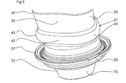
開示された実施形態では、バレル部分21cは、休止状態では、三つのコーナー部分25及び三つのサイド部分26を規定する三角形横断面形状を有する。各サイド部分26は、直線状にされ、三つのコーナー部分25のうち二つと接続する(図2,7及び9参照)。
In the disclosed embodiment, the
バレル部分21cは、原則として、いかなる多角形横断面形状も持つことができ、例えば正方形又は八角形の横断面形状を持つことができることが注意されるべきである。
It should be noted that the
乳頭カップライナー21の下端部分21bは、外側に延びる環状フランジ27を含む(図6参照)。環状フランジ27は、長尺スリーブ20の下端区域20bの端面に当接し、長尺スリーブ20に対する下端部分21bの軸方向の位置を維持する。
The
乳頭カップライナー21のバレル部材21cは、第一材料から作られ、乳頭カップライナー21の下端部分21bは、第二材料から作られる。第二材料は、第一材料と比較して高い剛性を有する。第一材料は、ゴム、黒ゴム、シリコーンゴム、弾性ポリマー(例えば熱可塑性エラストマー(TPE))、又は他のいずれかの好適な弾性材料からなるか、又はそれを含むことができる。第二材料は、ポリエテン、ポリプロペンなどの低い弾性を有する好適なポリマーからなるか、又はそれを含むことができる。
The
乳頭カップライナー21が長尺スリーブ20においてよじれることを防止するためには、長尺スリーブ20は、第一ロッキング部材28を含み(図8参照)、乳頭カップライナー21は、第一相補ロッキング部材29を含む(図9参照)。
To prevent the
第一ロッキング部材28は、長尺スリーブ20の下端区域20bに位置される。より正確には、第一ロッキング部材28は、下端区域20bの端面から下方に延びる突出部を含む。第一ロッキング部材28は、図8で見られるように、あり継ぎ形状を持つことができる。
The
第一相補ロッキング部材29は、乳頭カップライナー21の下端部分21b上に与えられる。より正確には、第一相補ロッキング部材29は、環状フランジ27上に与えられる。第一相補ロッキング部材29は、環状フランジ27に凹所を含むか、又はそれからなる。第一相補ロッキング部材29の凹所は、乳頭カップライナー21が長尺スリーブ20に装着されたとき、第一ロッキング部材28の突出部が第一相補ロッキング部材29の凹所に嵌合することを可能にする。
The first
従って、第一ロッキング部材28及び第一相補ロッキング部材29は、互いに係合し(図8及び9参照)。長手方向中心軸xのまわりの長尺スリーブ20に対する乳頭カップライナー21の回転を防止する。
Therefore, the first locking
さらに、第一ロッキング部材28及び第一相補ロッキング部材29は、長尺スリーブ20における乳頭カップライナー21の回転位置を規定する。
Further, the first locking
第一ロッキング部材28及び第一相補ロッキング部材29は、それぞれ一つより多い突出部及び凹所を含むことができることが注意されるべきである。
It should be noted that the first locking
さらに、長尺スリーブ20における乳頭カップライナー21のよじれは、リップ部材24の第二ロッキング部材31及び長尺スリーブ20の第二相補ロッキング部材32によって防止されることができる(図4,5及び11参照)。
Further, twisting of the
第二ロッキング部材31は、リップ部材24の下端から下方に延びる四つの突出部33を含む。第二相補ロッキング部材32は、長尺スリーブ20の上端区域20aで外側に延びる環状フランジ35中の四つの凹所34を含む。突出部33は、長尺スリーブ20に対する乳頭カップライナー21のよじれ又は回転を防止するために凹所34と相互作用するように構成される。リップ部材24が乳頭カップライナー21に取り付けられたとき、そしてリップ部材24を有する乳頭カップライナー21が長尺スリーブ20中に導入されたとき、第二ロッキング部材31の突出部33は、乳頭カップライナー21が長尺スリーブ20に対して回転方向でロックされるように第二相補ロッキング部材32の凹所34のそれぞれに嵌合する。
The
従って、第二ロッキング部材31及び第二相補ロッキング部材32は、長尺スリーブ20に対する、従って長手方向中心軸xのまわりの乳頭カップライナー21に対するリップ部材24の回転を防止するために互いに係合する。
Thus, the
第二ロッキング部材31及び第二相補ロッキング部材32は、四つより少ない又は四つより多い突出部33及び凹所34をそれぞれ含むことができることが注意されるべきである。
It should be noted that the
開示された実施形態では、長尺スリーブ20は、三つの開口40を含む(特に図7参照)。各開口40は、乳頭カップライナー21のサイド部分26のそれぞれとは反対側に与えられる(図2参照)。各開口40は、脈動乳首18及び閉鎖空間16の連絡通路を介して脈動室23中への及び脈動室23から外への脈動圧力の通過を可能にする。
In the disclosed embodiment, the
開口40は、長尺スリーブ20の下端区域20bを通って延び、長尺スリーブ20の下端区域20bのまわりに等距離で分布される。
The
開口40の数は、三つ以外であることができることが注意されるべきである。しかしながら、開口40の数は、好ましくはバレル部分20の多角形形状に対応することができ、従ってサイド部分26の数と同じであることができる。
It should be noted that the number of
バレル部分21cは、下端部分21bの近くでバレル部分21cのまわりに延びかつ外側に突出する突出リング41を含む(図6及び7参照)。突出リング41は、三つの直線部分42を含む。各直線部分42は、サイド部分26のそれぞれと軸方向に又は実質的に軸方向に整合されている。
The
従って、突出リング41は、突出リング41の上にバレル部分21cの多角形形状に対応する多角形形状を持つ。各直線部分42は、二つの湾曲部分43の間で延びる。
Therefore, the protruding
各直線部分42は、図6及び7で見られるように、開口40のそれぞれとは部分的に反対側に位置される。従って、開口40は、突出リング41と環状フランジ27の間で軸方向に位置される。直線部分42の一つは、図10の開口40の一つを通して見ることができる。
Each
長尺スリーブ20は、長尺スリーブ20の外側面49上で互いに並んで円周上に与えられた三つの別個の第一フック部材50を含む(図1,4〜6,8及び10参照)。第一フック部材50は、互いに並んで等距離に位置される。第一フック部材50は、同じ軸方向位置に位置される。
The
外側面49は、開示された実施形態では、上端区域20aから下端区域20bまで先細りになっている。
The
第一フック部材50の各々は、上方にかつ外側に傾斜する下部スライド面51、及び内側に延びる上部フック面52を有する(図6参照)。上部フック面52は、長手方向中心軸xに対して半径方向に又は実質的に半径方向に延びることができる。
Each of the
第一フック部材50の各々は、ヒール部材6のそれぞれと相互作用するように構成される。第一フック部材50及びヒール部材6は、第一フック部材50の各々がヒール部材6のそれぞれと整合されるときにコネクター2に対するカートリッジ1の第一回転位置を規定する。
Each of the
第一回転位置にあるとき、カートリッジ1は、長手方向中心軸xに沿ってコネクター2に挿入可能である。カートリッジ1の導入中、下部スライド面51は、ヒール部材6が第一フック部材50の下側面10を通るまで、ヒール部材6上で、特に上側面9と主要面8の間の面取り部上でスライドするだろう。第一フック部材50は、次いで第一フック部材50のフック面52がヒール部材6の下側面10に当接し、それによって係合されるように外側にスナップ嵌めするだろう(図2参照)。この挿入された位置から、カートリッジ1は、長手方向中心軸xに沿って反対方向に引っ張られることによってコネクター2から除去されることができない。
When in the first rotation position, the cartridge 1 can be inserted into the
さらに、長尺スリーブ20は、長尺スリーブ20の外側面49上に互いに並んで円周上に与えられた三つの別個の通路58を含む(図4,5及び10参照)。従って、第一フック部材50及び通路58は、長尺スリーブ20の外側面49のまわりに交互の順序で互いに並んで与えられる。また、通路58は、互いに並んで等距離に分布される。
Further, the
長尺スリーブ20はまた、通路58の二つにそれぞれの第二フック部材60を含む(図1及び4参照)。
The
従って、三つの通路58の二つは、第二フック部材を含み(図10参照)、一方三つ目の通路58は、第二フック部材を含まない(図8参照)。
Therefore, two of the three
第二フック部材60の各々は、内側に延びる下部フック面61、及び上方にかつ内側に傾斜する上部スライド面62を含む。
Each of the
従って、二つの第二フック部材60は、カートリッジ1が第一回転位置にないときにカートリッジ1が挿入されることを防止するために三つのヒール部材6のうちの二つのそれぞれと相互作用するように構成される。第一回転位置にないとき、第二フック部材60のうちの二つの下側フック面61は、ヒール部材6のうちの二つの上側9のそれぞれと係合し、従ってコネクター2中へのカートリッジ1のさらなる挿入を防止するだろう。
Therefore, the two
開示された実施形態では、長尺スリーブ20は、外側面49から外側に突出する三つの停止部材64を含む。各停止部材64は、細長い形状を持ち、軸方向に延びる。各停止部材64は、第一フック部材50のそれぞれの上に軸方向にかつそれぞれに隣接して与えられる。
In the disclosed embodiment, the
カートリッジ1がコネクター2中で挿入された位置にあるとき、停止部材64は、ヒール部材6と相互作用し、カートリッジ1が第一回転位置から第二回転位置まで第一方向にコネクター1に対して長手方向中心軸xのまわりに回転されることを可能にするだろう。
When the cartridge 1 is in the inserted position in the
第二回転位置では、各通路58は、ヒール部材6のそれぞれと軸方向に整合され、カートリッジ1は、コネクター2から除去可能である。カートリッジ1は、この第二回転位置では、コネクター2に対して長手方向中心軸xに沿って上方に移動可能であり、ヒール部材6は、通路58のそれぞれの上で案内されるだろう。通路58を通るヒール部材6のこの案内は、通路58の一つ(図8参照)が第二フック部材60を持たないことのおかげで容易になされる。
In the second rotation position, each
さらに、停止部材64は、ヒール部材6と相互作用し、カートリッジ1が第一回転位置から第二回転位置まで、第一方向とは反対の第二方向に回転されることを防止するだろう。
Further, the
開示された実施形態では、長尺スリーブ20は、三つの表面領域66を含む。各表面領域66は、円筒形の範囲を有し、第一フック部材50のそれぞれの上に与えられる。カートリッジ1がコネクター2中の挿入された位置にあるとき、各表面領域66は、ヒール部材6のそれぞれの主要面8とは反対側にあるだろう。表面領域66の上に傾斜領域67が与えられ、それは、上方にかつ外側に傾斜し、表面領域66を外側面49に接続する。
In the disclosed embodiment, the
各停止部材64は、表面領域66の一つと通路58の一つの間に与えられる。
Each
開示された実施形態では、長尺スリーブ20は、外側面49から外側に延びる三つのリブ部材68を含む。各リブ部材68は、細長い形状を持ち、軸方向に延びる。各リブ部材68は、第一フック部材50のそれぞれの上に軸方向にかつそれぞれに隣接して与えられる。リブ部材68は、停止部材64より表面領域66から低い高さを持ち、第一回転位置と第二回転位置の間のいずれかの方向に回転されるときにヒール部材6がリブ部材68の上に案内されることを可能にする。各リブ部材68は、通路58の一つと表面領域66の一つの間に与えられる。
In the disclosed embodiment, the
開示された実施形態では、長尺スリーブ20は、長尺スリーブ20の外側面49のまわりに延びる封止部材70を含む。封止部材70は、長尺スリーブ20の外側面49の周囲溝71に与えられる。周囲溝71は、開口40と第一フック部材50の間に軸方向に与えられる。封止部材70は、カートリッジ1が挿入される位置にあるとき、コネクター2の下部内側面75に当接し、閉鎖空間16を封止する(図2,3及び6参照)。
In the disclosed embodiment, the
開示された実施形態では、乳頭カップライナー21の下端部分21bは、長尺スリーブ20の下端区域20bを越えて延びる端部ノズル72を含む。端部ノズル72は、カートリッジ1がコネクター2中の挿入位置にあるとき、及び第一フック部材50がヒール部材6によって係合されるとき、乳導管4の上部15の封止面17に当接する円周外側面73を持つ(図2参照)。
In the disclosed embodiment, the
開示された乳頭カップでは、カートリッジ1は、容易に置き換えることができる。オペレーターは、そのときカートリッジ1のリップ部材24を把持し、それをコネクター2及び外殻3に対して回転することによって、乳頭カップを把持し、カートリッジ1を第一回転位置から第二回転位置まで回転する。
In the disclosed teat cup, the cartridge 1 can be easily replaced. The operator then grips the teat cup by grasping the
第一ロッキング部材及び第一相補ロッキング部材28,29のおかげで、そして第二ロッキング部材及び第二相補ロッキング部材31,32のおかげで、乳頭カップライナーは、長尺スリーブ21に対して同じ回転位置のままであり、従ってよじれないだろう。
Thanks to the first locking member and the first
第二回転位置では、カートリッジ1は、コネクター2及び外殻3に対して長手方向中心軸xに沿ってリップ部材24を引っ張ることによって、コネクター2及び外殻3から外に引っ張られることができる。
In the second rotation position, the cartridge 1 can be pulled out of the
新しいカートリッジ1は、次いでコネクター2及び外殻3中に挿入されることができる。挿入中、カートリッジ1は、ヒール部材6が第一フック部材50と、即ち第一回転位置に整合されるように配置される。カートリッジ1はさらに、第一フック部材50がスナップ嵌めされてヒール部材6と係合するまでリップ部材24を介して外殻3及びコネクター2中に押される。カートリッジ1の回転は、端部ノズル72が封止面17に達する前になされ、従って乳頭カップライナー21に及ぼされることができるねじり力は全くない。
The new cartridge 1 can then be inserted into the
本発明は、開示された実施形態に限定されず、添付の請求項の範囲内で変更及び修正されることができる。 The present invention is not limited to the disclosed embodiments, and can be modified and modified within the scope of the appended claims.
Claims (12)
長手方向中心軸(x)と平行に延びかつ上端区域(20a)及び下端区域(20b)を有する長尺スリーブ(20)と、
長尺スリーブ(20)に予め装着されかつ前記乳頭を受けるための内部空間(22)を有する乳頭カップライナー(21)と、
長尺スリーブ(20)の内側と乳頭カップライナー(21)の外側の間の脈動室(23)と、
を含み、乳頭カップライナー(21)が、
長尺スリーブ(20)の上端区域(20a)に位置される上端部分(21a)と、
長尺スリーブ(20)の下端区域(20b)に位置される下端部分(21b)と、
上端部分(21a)と下端部分(21b)の間に延びるバレル部分(21c)と、
を含み、
乳頭カップライナー(21)の下端部分(21b)が、外側に延びる環状フランジ(27)を含み、環状フランジ(27)が、長尺スリーブ(20)の下端区域(20b)の端面と当接しているものにおいて、
休止状態のバレル部分(21c)が、複数のコーナー部分(25)と、各々が前記コーナー部分(25)のうちの二つに接続する複数のサイド部分(26)とを規定する多角形横断面形状を有すること、
長尺スリーブ(20)が、第一ロッキング部材(28)を含むこと、
乳頭カップライナー(21)が、第一相補ロッキング部材(29)を含むこと、
第一ロッキング部材(28)及び第一相補ロッキング部材(29)が、長手方向中心軸(x)のまわりの長尺スリーブ(20)に対する乳頭カップライナー(21)の回転を防止するために互いに係合すること、
第一ロッキング部材(28)が、長尺スリーブ(20)の下端区域(20b)に位置され、第一相補ロッキング部材(29)が、乳頭カップライナー(21)の下端部分(21b)上に与えられていること、
第一相補ロッキング部材(29)が、環状フランジ(27)上に与えられていること、及び
第一相補ロッキング部材(29)が、環状フランジ(27)において凹所を含み、第一ロッキング部材(28)が、長尺スリーブ(20)の下端区域(20b)から第一相補ロッキング部材(29)の凹所中に延びる突出部を含むことを特徴とするカートリッジ。 A cartridge configured to form part of a teat cup, including a connector (2), wherein the teat cup is configured to be attached to the teat of a milking animal.
A long sleeve (20) extending parallel to the longitudinal central axis (x) and having an upper end area (20a) and a lower end area (20b).
A teat cup liner (21) pre-mounted on the long sleeve (20) and having an internal space (22) for receiving the teat.
A pulsating chamber (23) between the inside of the long sleeve (20) and the outside of the teat cup liner (21),
Including, the teat cup liner (21),
The upper end portion (21a) located in the upper end area (20a) of the long sleeve (20),
The lower end portion (21b) located in the lower end area (20b) of the long sleeve (20),
A barrel portion (21c) extending between the upper end portion (21a) and the lower end portion (21b),
Only including,
The lower end portion (21b) of the teat cup liner (21) includes an outwardly extending annular flange (27), and the annular flange (27) is in contact with the end face of the lower end area (20b) of the long sleeve (20). In what is
A polygonal cross section in which the dormant barrel portion (21c) defines a plurality of corner portions (25) and a plurality of side portions (26) each connecting to two of the corner portions (25). Having a shape,
The long sleeve (20) includes the first locking member (28),
The teat cup liner (21) includes a first complementary locking member (29) .
The first locking member (28) and the first complementary locking member (29) engage with each other to prevent rotation of the teat cup liner (21) with respect to the elongated sleeve (20) around the longitudinal central axis (x). To match ,
The first locking member (28) is located in the lower end area (20b) of the long sleeve (20) and the first complementary locking member (29) is provided on the lower end portion (21b) of the teat cup liner (21). Being done,
The first complementary locking member (29) is provided on the annular flange (27), and
The first complementary locking member (29) includes a recess in the annular flange (27) and the first locking member (28) is from the lower end area (20b) of the elongated sleeve (20) to the first complementary locking member (29). ) A cartridge characterized by including a protrusion extending into the recess.
Applications Claiming Priority (3)
| Application Number | Priority Date | Filing Date | Title |
|---|---|---|---|
| SE1650604-0 | 2016-05-04 | ||
| SE1650604 | 2016-05-04 | ||
| PCT/SE2017/050425 WO2017192092A1 (en) | 2016-05-04 | 2017-05-03 | A cartridge for a teatcup, and a teatcup |
Publications (2)
| Publication Number | Publication Date |
|---|---|
| JP2019514363A JP2019514363A (en) | 2019-06-06 |
| JP6934017B2 true JP6934017B2 (en) | 2021-09-08 |
Family
ID=58709532
Family Applications (1)
| Application Number | Title | Priority Date | Filing Date |
|---|---|---|---|
| JP2018554445A Active JP6934017B2 (en) | 2016-05-04 | 2017-05-03 | Cartridges and teat cups for teat cups |
Country Status (12)
| Country | Link |
|---|---|
| US (1) | US11160247B2 (en) |
| EP (1) | EP3451821B1 (en) |
| JP (1) | JP6934017B2 (en) |
| CN (1) | CN109068607B (en) |
| AU (1) | AU2017261141B2 (en) |
| BR (1) | BR112018072600B1 (en) |
| CA (1) | CA3022816A1 (en) |
| DK (1) | DK3451821T3 (en) |
| ES (1) | ES2839723T3 (en) |
| PL (1) | PL3451821T3 (en) |
| RU (1) | RU2737786C2 (en) |
| WO (1) | WO2017192092A1 (en) |
Families Citing this family (6)
| Publication number | Priority date | Publication date | Assignee | Title |
|---|---|---|---|---|
| WO2016099384A1 (en) * | 2014-12-19 | 2016-06-23 | Delaval Holding Ab | A teatcup |
| DK3700327T3 (en) * | 2017-10-26 | 2024-05-21 | Delaval Holding Ab | CARTRIDGE CONFIGURED TO FORM PART OF A TIPPER AND TIPPER |
| GB201902189D0 (en) | 2019-02-18 | 2019-04-03 | Avon Polymer Prod Ltd | Milking apparatus |
| USD1017927S1 (en) | 2020-12-16 | 2024-03-12 | Jakob Maier Und Wilfried Hatzack Erfinder Gbr | Teat engagement structure |
| IL281971A (en) * | 2021-04-01 | 2022-10-01 | Silvianu Ran | Milking machine and assembly |
| WO2023200926A1 (en) * | 2022-04-15 | 2023-10-19 | I B A, Inc. | Milking teatcup, teatcup shell, and inflation of a milking system |
Family Cites Families (31)
| Publication number | Priority date | Publication date | Assignee | Title |
|---|---|---|---|---|
| US1995283A (en) * | 1928-07-16 | 1935-03-19 | Universal Milking Machine Comp | Inflation tube for milking apparatus |
| US3874338A (en) * | 1972-10-09 | 1975-04-01 | Fritz Happel | Milking cup |
| US3818867A (en) | 1973-04-06 | 1974-06-25 | Hansen P Strange | Teat cup |
| ATA298576A (en) * | 1975-04-28 | 1985-04-15 | Kuenzler & Co | Teat cups for milk cups |
| JPS6134998Y2 (en) | 1981-12-14 | 1986-10-11 | ||
| CA1179289A (en) * | 1982-05-07 | 1984-12-11 | Nu Pulse New Zealand Limited | Milking apparatus |
| JPS58209924A (en) | 1982-05-27 | 1983-12-07 | ニユ−・パルス・ニユ−ジ−ランド・リミテツド | Improved milking instrument |
| SU1327852A1 (en) * | 1984-12-04 | 1987-08-07 | Воронежский сельскохозяйственный институт им.К.Д.Глинки | Teat cup |
| US4651676A (en) | 1985-12-04 | 1987-03-24 | Kupres Steven J | Silicone milking unit |
| SU1556602A1 (en) * | 1988-02-29 | 1990-04-15 | Сибирская Государственная Зональная Машиноиспытательная Станция | Teat cup |
| US4964368A (en) * | 1989-09-29 | 1990-10-23 | Versa Medical Technologies, Inc. | Milding teat cup having extended liner-shell seal |
| SE506122C2 (en) | 1996-03-27 | 1997-11-10 | Alfa Laval Agri Ab | Teat cup with valve housing |
| RU2122785C1 (en) * | 1996-05-27 | 1998-12-10 | Лаборатория биотехнических систем Уральского отделения РАН | Teat cup (versions) |
| DE19635719A1 (en) * | 1996-09-03 | 1998-03-05 | Jakob Maier | Teat rubber |
| SE9604053D0 (en) * | 1996-11-05 | 1996-11-05 | Alfa Laval Agri Ab | Teat rubber and process for the manufacture of a teat rubber |
| SE514503C2 (en) * | 1999-06-10 | 2001-03-05 | Delaval Holding Ab | Teat rubber, teat cup and milking organs |
| US6308656B1 (en) * | 1999-12-23 | 2001-10-30 | Constance J. Milbrath | Modular teat cup assembly |
| SE527508C2 (en) | 2004-06-10 | 2006-03-28 | Delaval Holding Ab | Teat rubber and teat cup |
| SE527446C2 (en) | 2004-06-10 | 2006-03-07 | Delaval Holding Ab | milking devices |
| US7966970B2 (en) * | 2005-07-19 | 2011-06-28 | M Management-Tex, Llc | Dairy inflation |
| SE529994C2 (en) | 2006-05-31 | 2008-02-05 | Delaval Holding Ab | teat |
| GB0716800D0 (en) * | 2007-08-29 | 2007-10-10 | Avon Polymer Prod Ltd | Milking apparatus and method |
| US8113145B2 (en) * | 2007-09-27 | 2012-02-14 | Gea Farm Technologies, Inc. | Teat cup liner |
| US8627785B2 (en) * | 2009-12-02 | 2014-01-14 | Avon Polymer Products Limited | Mouthpiece-vented teat cup inflation |
| WO2013095291A1 (en) * | 2011-12-22 | 2013-06-27 | Delaval Holding Ab | A milk conduit, and a milk conduit assembly |
| EP2838347A1 (en) * | 2012-04-18 | 2015-02-25 | DeLaval Holding AB | A lip member, a teatcup liner and a teatcup |
| EP3167708A1 (en) | 2012-05-07 | 2017-05-17 | DeLaval Holding AB | A teatcup liner |
| US9288962B2 (en) | 2012-11-02 | 2016-03-22 | Steven Brent Priest | Low-slip high-capacity teat cup liner |
| US10130068B2 (en) | 2013-05-02 | 2018-11-20 | Delaval Holding Ab | Cartridge, and a teat cup |
| US20150090183A1 (en) * | 2013-09-27 | 2015-04-02 | Gea Farm Technologies, Inc. | Anti-twist Liner and Shell for a Dairy Animal Teat Cup Assembly |
| US9408367B2 (en) * | 2013-10-28 | 2016-08-09 | Delaval Holding Ab | Teatcup liner with enhanced teat massage |
-
2017
- 2017-05-03 JP JP2018554445A patent/JP6934017B2/en active Active
- 2017-05-03 RU RU2018142534A patent/RU2737786C2/en active
- 2017-05-03 AU AU2017261141A patent/AU2017261141B2/en active Active
- 2017-05-03 CA CA3022816A patent/CA3022816A1/en active Pending
- 2017-05-03 US US16/098,773 patent/US11160247B2/en active Active
- 2017-05-03 CN CN201780027173.4A patent/CN109068607B/en active Active
- 2017-05-03 WO PCT/SE2017/050425 patent/WO2017192092A1/en unknown
- 2017-05-03 ES ES17723786T patent/ES2839723T3/en active Active
- 2017-05-03 EP EP17723786.4A patent/EP3451821B1/en active Active
- 2017-05-03 PL PL17723786T patent/PL3451821T3/en unknown
- 2017-05-03 BR BR112018072600-1A patent/BR112018072600B1/en active IP Right Grant
- 2017-05-03 DK DK17723786.4T patent/DK3451821T3/en active
Also Published As
| Publication number | Publication date |
|---|---|
| US11160247B2 (en) | 2021-11-02 |
| CA3022816A1 (en) | 2017-11-09 |
| WO2017192092A1 (en) | 2017-11-09 |
| NZ746826A (en) | 2024-05-31 |
| AU2017261141A1 (en) | 2018-10-25 |
| BR112018072600B1 (en) | 2022-04-19 |
| AU2017261141B2 (en) | 2022-02-17 |
| BR112018072600A2 (en) | 2019-02-19 |
| CN109068607B (en) | 2022-07-01 |
| US20190124880A1 (en) | 2019-05-02 |
| RU2018142534A3 (en) | 2020-07-03 |
| JP2019514363A (en) | 2019-06-06 |
| ES2839723T3 (en) | 2021-07-05 |
| RU2018142534A (en) | 2020-06-04 |
| DK3451821T3 (en) | 2020-12-14 |
| PL3451821T3 (en) | 2021-04-06 |
| EP3451821B1 (en) | 2020-11-18 |
| CN109068607A (en) | 2018-12-21 |
| EP3451821A1 (en) | 2019-03-13 |
| RU2737786C2 (en) | 2020-12-03 |
Similar Documents
| Publication | Publication Date | Title |
|---|---|---|
| JP6934017B2 (en) | Cartridges and teat cups for teat cups | |
| JP6934016B2 (en) | Cartridges and teat cups for teat cups | |
| RU2672495C2 (en) | Anti-twist liner and shell for dairy animal teat cup assembly | |
| JP6367224B2 (en) | Milk conduit, milk conduit device, milk receiving member, and milking member | |
| EA008546B1 (en) | A teatcup liner and a teatcup | |
| JP7186220B2 (en) | Connectors for teat cups attached to teats of animals to be milked, and teat cups | |
| JP7246377B2 (en) | Cartridge configured to form part of a teatcup and teatcup | |
| CA2829873C (en) | Milking liner |
Legal Events
| Date | Code | Title | Description |
|---|---|---|---|
| A521 | Request for written amendment filed |
Free format text: JAPANESE INTERMEDIATE CODE: A821 Effective date: 20181016 |
|
| A621 | Written request for application examination |
Free format text: JAPANESE INTERMEDIATE CODE: A621 Effective date: 20200424 |
|
| A977 | Report on retrieval |
Free format text: JAPANESE INTERMEDIATE CODE: A971007 Effective date: 20201030 |
|
| A131 | Notification of reasons for refusal |
Free format text: JAPANESE INTERMEDIATE CODE: A131 Effective date: 20201124 |
|
| A521 | Request for written amendment filed |
Free format text: JAPANESE INTERMEDIATE CODE: A523 Effective date: 20210222 |
|
| TRDD | Decision of grant or rejection written | ||
| A01 | Written decision to grant a patent or to grant a registration (utility model) |
Free format text: JAPANESE INTERMEDIATE CODE: A01 Effective date: 20210803 |
|
| A61 | First payment of annual fees (during grant procedure) |
Free format text: JAPANESE INTERMEDIATE CODE: A61 Effective date: 20210820 |
|
| R150 | Certificate of patent or registration of utility model |
Ref document number: 6934017 Country of ref document: JP Free format text: JAPANESE INTERMEDIATE CODE: R150 |
|
| R250 | Receipt of annual fees |
Free format text: JAPANESE INTERMEDIATE CODE: R250 |