JP6930451B2 - Radioactive waste refilling device and how to use it - Google Patents
Radioactive waste refilling device and how to use it Download PDFInfo
- Publication number
- JP6930451B2 JP6930451B2 JP2018024663A JP2018024663A JP6930451B2 JP 6930451 B2 JP6930451 B2 JP 6930451B2 JP 2018024663 A JP2018024663 A JP 2018024663A JP 2018024663 A JP2018024663 A JP 2018024663A JP 6930451 B2 JP6930451 B2 JP 6930451B2
- Authority
- JP
- Japan
- Prior art keywords
- cask
- radioactive waste
- carry
- adapter
- storage
- Prior art date
- Legal status (The legal status is an assumption and is not a legal conclusion. Google has not performed a legal analysis and makes no representation as to the accuracy of the status listed.)
- Active
Links
Images


Landscapes
- Processing Of Solid Wastes (AREA)
- Load-Engaging Elements For Cranes (AREA)
Description
本開示は、放射性廃棄物詰替装置及びその使用方法に関するものである。 The present disclosure relates to a radioactive waste refilling device and its usage.
一般に、原子力施設において発生する被処理液としての放射性廃液は、ガラス固化施設のガラス溶融炉により溶融されたガラスと混合され、ガラス固化体として処理される。 Generally, radioactive waste liquid as a liquid to be treated generated in a nuclear facility is mixed with glass melted by a glass melting furnace of a vitrification facility and treated as a vitrified body.
前記ガラス固化施設において、前記ガラス固化体は、小型で金属製の搬出用キャスクに収容されて保管庫に貯蔵された後、ガラス固化施設の外部に搬出され、放射性廃棄物保管施設に保管される。 In the vitrification facility, the vitrified body is housed in a small metal export cask and stored in a storage, then carried out of the vitrification facility and stored in a radioactive waste storage facility. ..
ここで、前記搬出用キャスクは、三本のガラス固化体を収容できるものとなっているが、前記放射性廃棄物保管施設で長期に保管するには小さいため、前記搬出用キャスクより大型で輸送と保管を兼用した金属製の輸送保管用キャスクに詰め替える必要がある。又、キャスクの代わりに金属製のキャニスタに使用済燃料を充填して半地下施設に貯蔵する、いわゆるボールト貯蔵も国内外で既に実施されている。該ボールト貯蔵の場合も、ガラス固化体は、長距離輸送するためには、前記搬出用キャスクより大型の輸送保管用キャニスタに詰め替える必要がある。 Here, the carry-out cask is capable of accommodating three vitrified bodies, but since it is small for long-term storage in the radioactive waste storage facility, it is larger than the carry-out cask for transportation. It is necessary to refill the metal transport and storage cask that also serves as storage. In addition, so-called vault storage, in which spent fuel is filled in a metal canister instead of a cask and stored in a semi-underground facility, has already been implemented in Japan and overseas. Also in the case of the vault storage, the vitrified body needs to be refilled with a transport storage canister larger than the carry-out cask in order to transport the vitrified body over a long distance.
従来、前記搬出用キャスクから輸送保管用キャスクへの詰め替えを行うためには、放射性廃棄物保管施設に外部から遮蔽された専用の詰替設備を新たに建設する方式が考えられていた。 Conventionally, in order to refill the carry-out cask to the transport storage cask, a method has been considered in which a dedicated refill facility shielded from the outside is newly constructed in the radioactive waste storage facility.
尚、使用済み核燃料をキャスクから取り出してバスケットに移し替える装置と関連する一般的技術水準を示すものとしては、例えば、特許文献1がある。 For example, Patent Document 1 shows a general technical level related to an apparatus for removing spent nuclear fuel from a cask and transferring it to a basket.
しかしながら、前述のように、詰替設備を新設するのでは、放射性廃棄物保管施設に専用の土地や空間を新たに確保しなければならなくなると共に、既設建物の改造が必要になるという不具合を有していた。 However, as mentioned above, if a new refill facility is installed, it will be necessary to secure new dedicated land and space for the radioactive waste storage facility, and there will be a problem that the existing building will need to be remodeled. Was.
因みに、特許文献1に開示されている発明は、あくまでも使用済み核燃料をキャスクから取り出してバスケットに移し替える装置であって、特許文献1に、キャスク間におけるガラス固化体の詰め替えに関する記載はない。又、装置的にも揺動アームが隔壁下に振子運動する構造を有し、水路内に揺動アームが振子運動できるスペースを広く設けなければならず、既設建物の改造も避けられない。 Incidentally, the invention disclosed in Patent Document 1 is an apparatus for taking out spent nuclear fuel from a cask and transferring it to a basket, and Patent Document 1 does not describe refilling a vitrified material between cask. Further, as a device, the swing arm has a structure in which the swing arm moves pendulum under the partition wall, and a wide space for the swing arm to move in the pendulum must be provided in the water channel, and remodeling of the existing building is unavoidable.
本開示は、上記従来の問題点に鑑みてなしたもので、詰替設備新設に伴う放射性廃棄物保管施設専用の土地や空間の確保並びに既設建物の改造を不要とし得る放射性廃棄物詰替装置及びその使用方法を提供しようとするものである。 This disclosure is made in view of the above-mentioned conventional problems, and is a radioactive waste refilling device that can secure land and space dedicated to the radioactive waste storage facility and remodel the existing building due to the new construction of the refilling equipment. And its usage is intended to be provided.
上記目的を達成するために、本開示の放射性廃棄物詰替装置は、搬出用キャスクに収容された放射性廃棄物を輸送保管用キャスクへ詰め替える放射性廃棄物詰替装置であって、
前記輸送保管用キャスクは、上端に開口部が形成された容器本体と、該容器本体の軸線方向へ前記放射性廃棄物を複数本収容自在で且つ軸線と直交する断面において軸心部に一個とその周囲に複数個配設されるよう前記容器本体の内部に形成された区分収容部と、該区分収容部の上端挿入口に着脱自在に取り付けられる遮蔽プラグと、該遮蔽プラグ全てを覆うよう前記容器本体の開口部に対し着脱自在に取り付けられる蓋体とを備え、
前記搬出用キャスクは、前記放射性廃棄物と遮蔽プラグとを収容自在で且つ該放射性廃棄物と遮蔽プラグとを通過させる導入出口が底部に形成された胴部と、該胴部の上部に旋回自在に配設され且つ前記放射性廃棄物と遮蔽プラグとを吊上・吊下自在な吊上機構と、前記導入出口に開閉自在に配設され且つ該導入出口を前記輸送保管用キャスクの少なくとも一個の区分収容部の上端挿入口に連通させるシャッタとを備えることができる。
In order to achieve the above object, the radioactive waste refilling device of the present disclosure is a radioactive waste refilling device that refills the radioactive waste contained in the carry-out cask into the transport storage cask.
The transport and storage cask has a container body having an opening at the upper end, and one at the axial center in a cross section capable of accommodating a plurality of the radioactive wastes in the axial direction of the container body and orthogonal to the axis. A compartmentalized housing portion formed inside the container body so as to be arranged around a plurality of containers, a shielding plug detachably attached to the upper end insertion port of the compartmentalized housing portion, and the container so as to cover all of the shielding plugs. Equipped with a lid that can be detachably attached to the opening of the main body
The carry-out cask is capable of accommodating the radioactive waste and the shielding plug, and has a body portion having an introduction outlet formed at the bottom for passing the radioactive waste and the shielding plug, and a swivel upper part of the body portion. A lifting mechanism that can suspend and suspend the radioactive waste and the shielding plug, and at least one of the transport and storage casks that can be opened and closed at the introduction outlet. A shutter that communicates with the upper end insertion port of the compartmentalized housing unit can be provided.
前記放射性廃棄物詰替装置においては、前記搬出用キャスクと輸送保管用キャスクとの間に介装されるアダプタを備え、
前記アダプタは、前記輸送保管用キャスクの開口部に対し旋回自在に配設され且つ前記搬出用キャスクが載置されるアダプタ本体と、前記搬出用キャスクの導入出口を前記輸送保管用キャスクの軸心部の区分収容部の上端挿入口とその周囲に配設される一個の区分収容部の上端挿入口とに連通させるよう前記アダプタ本体に穿設された通過口とを備えることができる。
The radioactive waste refilling device includes an adapter interposed between the carrying-out cask and the transport storage cask.
The adapter is arranged so as to be rotatable with respect to the opening of the transport / storage cask, and the adapter main body on which the carry-out cask is placed and the introduction outlet of the carry-out cask are the axes of the transport / storage cask. It is possible to provide a passage port bored in the adapter main body so as to communicate with the upper end insertion port of the section accommodating portion of the portion and the upper end insertion port of one section accommodating portion arranged around the upper end insertion port.
又、前記放射性廃棄物詰替装置においては、前記搬出用キャスクと輸送保管用キャスクとの間に介装されるアダプタを備え、
前記アダプタは、前記輸送保管用キャスクの開口部に対し旋回自在に且つ前記輸送保管用キャスクの軸線と直交する方向へ移動自在に配設されて前記搬出用キャスクが載置されるアダプタ本体と、前記搬出用キャスクの導入出口を前記輸送保管用キャスクの一個の区分収容部の上端挿入口に連通させるよう前記アダプタ本体に穿設された通過口とを備えることもできる。
Further, the radioactive waste refilling device is provided with an adapter interposed between the carrying-out cask and the transport storage cask.
The adapter body is arranged so as to be rotatable with respect to the opening of the transport / storage cask and movable in a direction orthogonal to the axis of the transport / storage cask, and the adapter body on which the carry-out cask is placed. It is also possible to provide a passage port bored in the adapter body so that the introduction outlet of the carry-out cask communicates with the upper end insertion port of one of the transport storage casks.
一方、前記アダプタを備えていない放射性廃棄物詰替装置の使用方法として、
前記輸送保管用キャスクの蓋体を開く蓋体開放工程と、
前記導入出口が区分収容部の上端挿入口位置と合致するよう搬出用キャスクを輸送保管用キャスクの上に載置する搬出用キャスク載置工程と、
前記遮蔽プラグを吊上機構で吊り上げて区分収容部の上端挿入口を開く遮蔽プラグ開放工程と、
開かれた区分収容部の上端挿入口に合わせて放射性廃棄物を搬出用キャスクの内部で旋回させる搬出用キャスク内部旋回工程と、
前記放射性廃棄物を区分収容部に吊り下げて納める収容工程と、
前記放射性廃棄物が収容された区分収容部の上端挿入口に遮蔽プラグを装着する遮蔽プラグ装着工程と、
全ての区分収容部が満杯となった後に輸送保管用キャスクの容器本体の開口部を蓋体で閉じる蓋体装着工程と
を行うことができる。
On the other hand, as a method of using a radioactive waste refilling device that does not have the adapter,
The lid opening step of opening the lid of the transport and storage cask, and
The carry-out cask mounting process in which the carry-out cask is placed on the transport storage cask so that the introduction outlet matches the position of the upper end insertion port of the compartmentalized housing portion.
A shielding plug opening process in which the shielding plug is lifted by a lifting mechanism to open the upper end insertion port of the compartmentalized housing portion, and
The internal swivel process of the carry-out cask, which swirls the radioactive waste inside the carry-out cask according to the upper end insertion port of the opened compartmentalized housing,
A storage process in which the radioactive waste is suspended and stored in a compartmentalized storage unit,
The process of attaching the shielding plug to the upper end insertion port of the compartmentalized storage unit in which the radioactive waste is contained, and the process of attaching the shielding plug.
After all the compartmentalized compartments are full, the lid mounting step of closing the opening of the container body of the transport storage cask with a lid can be performed.
又、前記アダプタを備えている放射性廃棄物詰替装置の使用方法として、
前記輸送保管用キャスクの蓋体を開く蓋体開放工程と、
前記通過口が区分収容部の上端挿入口位置と合致するようアダプタを輸送保管用キャスクの開口部に載置するアダプタ載置工程と、
前記搬出用キャスクをアダプタの上に載置する搬出用キャスク載置工程と、
前記遮蔽プラグを吊上機構で吊り上げて区分収容部の上端挿入口を開く遮蔽プラグ開放工程と、
開かれた区分収容部の上端挿入口に合わせて放射性廃棄物を搬出用キャスクの内部で旋回させる搬出用キャスク内部旋回工程と、
前記放射性廃棄物を区分収容部に吊り下げて納める収容工程と、
前記放射性廃棄物が収容された区分収容部の上端挿入口に遮蔽プラグを装着する遮蔽プラグ装着工程と、
全ての区分収容部が満杯となった後に前記アダプタを撤去するアダプタ撤去工程と、
前記アダプタが撤去された輸送保管用キャスクの容器本体の開口部を蓋体で閉じる蓋体装着工程と
を行うことができる。
Also, as a method of using the radioactive waste refilling device equipped with the adapter,
The lid opening step of opening the lid of the transport and storage cask, and
An adapter mounting step of mounting the adapter in the opening of the transport storage cask so that the passage port matches the position of the upper end insertion port of the compartmentalized housing portion.
The carry-out cask mounting step of mounting the carry-out cask on the adapter, and
A shielding plug opening process in which the shielding plug is lifted by a lifting mechanism to open the upper end insertion port of the compartmentalized housing portion, and
The internal swivel process of the carry-out cask, which swirls the radioactive waste inside the carry-out cask according to the upper end insertion port of the opened compartmentalized housing,
A storage process in which the radioactive waste is suspended and stored in a compartmentalized storage unit,
The process of attaching the shielding plug to the upper end insertion port of the compartmentalized storage unit in which the radioactive waste is contained, and the process of attaching the shielding plug.
The adapter removal process, which removes the adapter after all the compartments are full,
A lid mounting step of closing the opening of the container body of the transport storage cask from which the adapter has been removed with a lid can be performed.
本開示の放射性廃棄物詰替装置及びその使用方法によれば、詰替設備新設に伴う放射性廃棄物保管施設専用の土地や空間の確保並びに既設建物の改造を不要とし得るという優れた効果を奏し得る。 According to the radioactive waste refilling device and the method of using the radioactive waste refilling device of the present disclosure, the excellent effect of securing the land and space dedicated to the radioactive waste storage facility and remodeling the existing building due to the new construction of the refilling equipment can be achieved. obtain.
以下、本発明の実施の形態を添付図面を参照して説明する。 Hereinafter, embodiments of the present invention will be described with reference to the accompanying drawings.
図1〜図24は本発明の放射性廃棄物詰替装置及びその使用方法の第一実施例である。 1 to 24 are first examples of the radioactive waste refilling device of the present invention and the method of using the same.
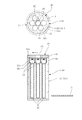
第一実施例の場合、搬出用キャスク10(図3〜図6参照)に収容された放射性廃棄物20を輸送保管用キャスク30(図1及び図2参照)へ詰め替えるようになっている。
In the case of the first embodiment, the
前記放射性廃棄物20は、例えば、放射性廃液をガラスと混合してキャニスタ21に充填し固化させたガラス固化体22である。
The
前記輸送保管用キャスク30は、図1及び図2に示す如く、容器本体31と、区分収容部32と、遮蔽プラグ33と、蓋体34とを備えている。
As shown in FIGS. 1 and 2, the transport and
前記容器本体31は、上端に開口部31aが形成され、底部が閉塞された筒状体31bで構成されている。
The
前記区分収容部32は、前記容器本体31の軸線方向へ前記ガラス固化体22を複数本収容自在で且つ軸線と直交する断面において軸心部に一個とその周囲に複数個配設されるよう前記容器本体31の内部に形成されている。尚、図1及び図2の例では、一個の区分収容部32に対しガラス固化体22が上下方向へ四本収容されるようになっているが、その本数は四本に限定されるものではない。又、前記容器本体31の軸心部に配設される一個の区分収容部32に対し、その周囲に六個の区分収容部32が配設されているが、その個数は六個に限定されるものではない。
The
前記遮蔽プラグ33は、前記区分収容部32の上端挿入口32aに着脱自在に取り付けられている。前記区分収容部32の上端挿入口32aは、下方へ向けて内径が漸次収縮する縮径部32bを備え、前記遮蔽プラグ33の下部外周面は前記縮径部32bに倣うように形成されている。
The shielding
前記蓋体34は、前記遮蔽プラグ33全てを覆うよう前記容器本体31の開口部31aに対し着脱自在に取り付けられている。
The
前記搬出用キャスク10は、図3〜図6に示す如く、胴部11と、吊上機構12と、シャッタ13とを備えている。
As shown in FIGS. 3 to 6, the carry-out
前記胴部11は、前記ガラス固化体22と遮蔽プラグ33とを収容自在で且つ該ガラス固化体22と遮蔽プラグ33とを通過させる導入出口11aが底部に形成されている。尚、前記胴部11は、ガラス固化体22を二本と遮蔽プラグ33を一本収容できるようになっているが、例えば、ガラス固化体22を三本と遮蔽プラグ33を一本収容することも可能であり、搬出側の天井クレーンの容量に適合する範囲で増やすことは可能である。
The
前記吊上機構12は、前記胴部11の上端部に旋回自在となるよう配設された天井部12aにホイスト12bと吊具12cとを取り付けて構成されている。これにより、前記吊上機構12は、前記ガラス固化体22と遮蔽プラグ33とを吊上・吊下自在となるよう、前記胴部11の上部に旋回自在に配設されている。前記吊上機構12を構成するホイスト12b及び吊具12cは、前記胴部11における容量に合わせて三組設けられているが、前記胴部11がガラス固化体22を三本と遮蔽プラグ33を一本収容するようになっている場合には、それに合わせて四組設ければ良い。尚、前記天井部12aを旋回させる機構は、特に図示していないが、例えば、旋回環の外周面にラックを刻設し、該ラックに噛合させたピニオンをモータにより減速機を介して駆動する旋回機構やその他の機構を採用することができる。
The
前記シャッタ13は、図3及び図4と図5及び図6に示す如く、前記導入出口11aに開閉自在に配設され且つ該導入出口11aを前記輸送保管用キャスク30の一個の区分収容部32の上端挿入口32aに連通させるようになっている(図9及び図16参照)。尚、前記シャッタ13を開閉する機構は、特に図示していないが、例えば、流体圧シリンダによりシャッタ13を押し引きする駆動機構やその他の機構を採用することができる。
As shown in FIGS. 3 and 4, 5 and 6, the
次に、上記第一実施例の作用を説明する。 Next, the operation of the first embodiment will be described.
先ず、図7に示す如く、輸送保管用キャスク30の蓋体34が取り外され、容器本体31の上端の開口部31aが開放される。尚、図7〜図22には、側断面図と、それに対応する平断面図とを別図とせずに、あえて側断面図の上方に平断面図を併記している。これは、説明を理解しやすくするためである。
First, as shown in FIG. 7, the
続いて、図8に示す如く、前記輸送保管用キャスク30の軸心部の区分収容部32に導入出口11aが合致するよう、前記輸送保管用キャスク30の上に搬出用キャスク10が載置される。この時点で、前記搬出用キャスク10には二本のガラス固化体22が収容され、前記搬出用キャスク10のシャッタ13は閉じている。因みに、前記搬出用キャスク10に三本のガラス固化体22を収容していないのは、後述する遮蔽プラグ33を一時的に収容するスペースを確保するためである。
Subsequently, as shown in FIG. 8, the carry-out
尚、図8〜図20の側断面図において、奥側に旋回された吊具12cと、該吊具12cに吊り下げられるガラス固化体22、遮蔽プラグ33については、図示をあえて省略している。
In the side sectional views of FIGS. 8 to 20, the hanging
この後、図9に示す如く、前記搬出用キャスク10のシャッタ13が開かれて輸送保管用キャスク30の軸心部の区分収容部32の遮蔽プラグ33が吊り上げられ、該遮蔽プラグ33が搬出用キャスク10の内部に収容される。
After that, as shown in FIG. 9, the
次に、図10に示す如く、前記搬出用キャスク10の吊上機構12を構成する天井部12aが旋回して一本目のガラス固化体22が輸送保管用キャスク30の軸心部の区分収容部32の上方に位置合わせされる。
Next, as shown in FIG. 10, the
そして、図11に示す如く、前記搬出用キャスク10の吊上機構12を構成するホイスト12bにより吊具12cが巻き下げられ、一本目のガラス固化体22が輸送保管用キャスク30の軸心部の区分収容部32に吊り降ろされる。前記吊具12cから一本目のガラス固化体22が切り離され、前記ホイスト12bにより吊具12cが巻き上げられると、前記天井部12aが旋回して次の二本目のガラス固化体22が輸送保管用キャスク30の軸心部の区分収容部32の上方に位置合わせされる。
Then, as shown in FIG. 11, the
続いて、図12に示す如く、前記ホイスト12bにより吊具12cが巻き下げられ、二本目のガラス固化体22が輸送保管用キャスク30の軸心部の区分収容部32に吊り降ろされる。前記吊具12cから二本目のガラス固化体22が切り離され、前記ホイスト12bにより吊具12cが巻き上げられると、前記天井部12aが旋回して遮蔽プラグ33が輸送保管用キャスク30の軸心部の区分収容部32の上方に位置合わせされる。
Subsequently, as shown in FIG. 12, the hoist 12b winds down the
この後、図13に示す如く、前記ホイスト12bにより吊具12cが巻き下げられ、前記遮蔽プラグ33が輸送保管用キャスク30の軸心部の区分収容部32の上端挿入口32aに戻される。
After that, as shown in FIG. 13, the
次に、空となった搬出用キャスク10が撤去され、新たに二本のガラス固化体22が収容された搬出用キャスク10が輸送保管用キャスク30の上に載置される。そして、図8〜図13に示す操作と同様の操作が繰り返されると、二本のガラス固化体22の上に更に二本のガラス固化体22が収容される形となり、図14に示す如く、前記輸送保管用キャスク30の軸心部の区分収容部32がガラス固化体22で満杯となる。
Next, the empty carry-out
続いて、図15に示す如く、前記輸送保管用キャスク30の軸心部周囲の一個の区分収容部32に導入出口11aが合致するよう、前記輸送保管用キャスク30の上に搬出用キャスク10が載置される。この時点で、前述と同様、遮蔽プラグ33を一時的に収容するスペースを確保するために、前記搬出用キャスク10には二本のガラス固化体22が収容され、前記搬出用キャスク10のシャッタ13は閉じている。
Subsequently, as shown in FIG. 15, the carry-out
この後、図16に示す如く、前記搬出用キャスク10のシャッタ13が開かれて輸送保管用キャスク30の軸心部周囲の区分収容部32の遮蔽プラグ33が吊り上げられ、該遮蔽プラグ33が搬出用キャスク10の内部に収容される。
After that, as shown in FIG. 16, the
次に、図17に示す如く、前記搬出用キャスク10の吊上機構12を構成する天井部12aが旋回して一本目のガラス固化体22が輸送保管用キャスク30の軸心部周囲の区分収容部32の上方に位置合わせされる。
Next, as shown in FIG. 17, the
そして、図18に示す如く、前記搬出用キャスク10の吊上機構12を構成するホイスト12bにより吊具12cが巻き下げられ、一本目のガラス固化体22が輸送保管用キャスク30の軸心部周囲の区分収容部32に吊り降ろされる。前記吊具12cから一本目のガラス固化体22が切り離され、前記ホイスト12bにより吊具12cが巻き上げられると、前記天井部12aが旋回して次の二本目のガラス固化体22が輸送保管用キャスク30の軸心部周囲の区分収容部32の上方に位置合わせされる。
Then, as shown in FIG. 18, the hoist 12c constituting the
続いて、図19に示す如く、前記ホイスト12bにより吊具12cが巻き下げられ、二本目のガラス固化体22が輸送保管用キャスク30の軸心部周囲の区分収容部32に吊り降ろされる。前記吊具12cから二本目のガラス固化体22が切り離され、前記ホイスト12bにより吊具12cが巻き上げられると、前記天井部12aが旋回して遮蔽プラグ33が輸送保管用キャスク30の軸心部周囲の区分収容部32の上方に位置合わせされる。
Subsequently, as shown in FIG. 19, the hoist 12b winds down the
この後、図20に示す如く、前記ホイスト12bにより吊具12cが巻き下げられ、前記遮蔽プラグ33が輸送保管用キャスク30の軸心部周囲の区分収容部32の上端挿入口32aに戻される。
After that, as shown in FIG. 20, the hoist 12b winds down the
次に、空となった搬出用キャスク10が撤去され、新たに二本のガラス固化体22が収容された搬出用キャスク10が輸送保管用キャスク30の上に載置される。そして、図15〜図20に示す操作と同様の操作が繰り返されると、二本のガラス固化体22の上に更に二本のガラス固化体22が収容される形となり、図21に示す如く、前記輸送保管用キャスク30の軸心部の区分収容部32と、軸心部周囲の一個の区分収容部32とがガラス固化体22で満杯となる。
Next, the empty carry-out
以下、図15〜図20に示す操作と同様の操作が、前記輸送保管用キャスク30の残り全ての軸心部周囲の区分収容部32に対して繰り返される。最終的に、図22に示す如く、前記輸送保管用キャスク30の軸心部の区分収容部32と、全ての軸心部周囲の区分収容部32とがガラス固化体22で満杯になると、前記遮蔽プラグ33全てを覆うよう前記容器本体31の開口部31aに対し蓋体34が取り付けられる。
Hereinafter, the same operation as that shown in FIGS. 15 to 20 is repeated for the
これにより、第一実施例の場合、図23に示す如く、ガラス固化施設において、搬出用キャスク10から輸送保管用キャスク30へのガラス固化体22の詰め替えを、専用の詰替設備を新たに建設することなく行うことが可能となる。又、図24に示す如く、放射性廃棄物保管施設において、搬出用キャスク10から輸送保管用キャスク30へのガラス固化体22の詰め替えを、専用の詰替設備を新たに建設することなく行うことも可能となる。
As a result, in the case of the first embodiment, as shown in FIG. 23, in the vitrification facility, the
即ち、第一実施例では、従来のように、詰替設備を新設するのとは異なり、放射性廃棄物保管施設に専用の土地や空間を新たに確保しなくて済むと共に、既設建物を改造しなくて済む。 That is, in the first embodiment, unlike the conventional case where a refilling facility is newly installed, it is not necessary to newly secure a dedicated land or space for the radioactive waste storage facility, and the existing building is remodeled. You don't have to.
又、前記遮蔽プラグ33が前記区分収容部32の上端挿入口32aに着脱自在に取り付けられているため、前記輸送保管用キャスク30の容器本体31の開口部31aに対し着脱自在に取り付けられる蓋体34を薄くすることが可能となる。因みに、仮に前記遮蔽プラグ33がないと、蓋体34に遮蔽と気密機能の両方が必要とされることから、蓋体34は厚くせざるを得ない。
Further, since the shielding
こうして、詰替設備新設に伴う放射性廃棄物保管施設専用の土地や空間の確保並びに既設建物の改造を不要とし得る。 In this way, it is possible to eliminate the need for securing land and space dedicated to the radioactive waste storage facility and remodeling the existing building due to the new construction of the refill facility.
図25〜図39は本発明の放射性廃棄物詰替装置及びその使用方法の第二実施例である。図25〜図39中、図1〜図24と同一の符号を付した部分は同一物を表わしており、基本的な構成は図1〜図24に示す第一実施例と同様である。尚、図25〜図39には、図7〜図22と同様、側断面図と、それに対応する平断面図とを別図とせずに、あえて側断面図の上方に平断面図を併記している。 25 to 39 are the second embodiment of the radioactive waste refilling apparatus of the present invention and the method of using the same. In FIGS. 25 to 39, the parts having the same reference numerals as those in FIGS. 1 to 24 represent the same objects, and the basic configuration is the same as that of the first embodiment shown in FIGS. 1 to 24. In addition, in FIGS. 25 to 39, similarly to FIGS. 7 to 22, the side cross-sectional view and the corresponding plan cross-sectional view are not separately shown, and the plan section is intentionally shown above the side cross-sectional view. ing.
第二実施例の特徴とするところは、図25〜図39に示す如く、搬出用キャスク10と輸送保管用キャスク30との間にアダプタ40を介装するようにした点にある。
The feature of the second embodiment is that the
前記アダプタ40は、アダプタ本体41と、通過口42とを備えている。
The
前記アダプタ本体41は、前記輸送保管用キャスク30の開口部31aに対し旋回自在に配設され、前記搬出用キャスク10が載置されるようになっている。尚、前記アダプタ本体41を旋回させる機構は、特に図示していないが、例えば、旋回環の外周面にラックを刻設し、該ラックに噛合させたピニオンをモータにより減速機を介して駆動する旋回機構やその他の機構を採用することができる。
The adapter
前記通過口42は、前記搬出用キャスク10の導入出口11aを前記輸送保管用キャスク30の軸心部の区分収容部32の上端挿入口32aとその周囲に配設される一個の区分収容部32の上端挿入口32aとに連通させるよう前記アダプタ本体41に穿設されている。
In the
尚、前記搬出用キャスク10の胴部11の底部に形成される導入出口11aは、図26及び図27に示す如く、前記アダプタ40の二個の通過口42を介して、前記輸送保管用キャスク30の軸心部の区分収容部32と一個の軸心部周囲の区分収容部32の合わせて二個の上端挿入口32aに連通させることができるようになっている。因みに、前記シャッタ13は、図27に示す如く開放された際に、前記導入出口11aを前記輸送保管用キャスク30の軸心部の区分収容部32と一個の軸心部周囲の区分収容部32の合わせて二個の上端挿入口32aに連通させるようになっている。
As shown in FIGS. 26 and 27, the
次に、上記第二実施例の作用を説明する。 Next, the operation of the second embodiment will be described.
先ず、第一実施例の場合と同様、図7に示す如く、輸送保管用キャスク30の蓋体34が取り外され、容器本体31の上端の開口部31aが開放される。
First, as in the case of the first embodiment, as shown in FIG. 7, the
次に、図25に示す如く、前記輸送保管用キャスク30の軸心部の区分収容部32と、軸心部周囲の区分収容部32とに通過口42が合致するようアダプタ40が載置される。
Next, as shown in FIG. 25, the
続いて、図26に示す如く、前記輸送保管用キャスク30の軸心部の区分収容部32と、軸心部周囲の区分収容部32とに前記アダプタ40の通過口42を介して導入出口11aが合致するよう、前記アダプタ40の上に搬出用キャスク10が載置される。この時点で、前記搬出用キャスク10には二本のガラス固化体22が収容され、前記搬出用キャスク10のシャッタ13は閉じている。
Subsequently, as shown in FIG. 26, the
尚、図26〜図38の側断面図において、奥側に旋回された吊具12cと、該吊具12cに吊り下げられるガラス固化体22、遮蔽プラグ33については、図示をあえて省略している。
In the side sectional views of FIGS. 26 to 38, the hanging
この後、図27に示す如く、前記搬出用キャスク10のシャッタ13が開かれて輸送保管用キャスク30の軸心部の区分収容部32の遮蔽プラグ33が吊り上げられ、該遮蔽プラグ33がアダプタ40の通過口42を介して搬出用キャスク10の内部に収容される。
After that, as shown in FIG. 27, the
次に、図28に示す如く、前記搬出用キャスク10の吊上機構12を構成する天井部12aが旋回して一本目のガラス固化体22が輸送保管用キャスク30の軸心部の区分収容部32とアダプタ40の通過口42の上方に位置合わせされる。
Next, as shown in FIG. 28, the
そして、図29に示す如く、前記搬出用キャスク10の吊上機構12を構成するホイスト12bにより吊具12cが巻き下げられ、一本目のガラス固化体22がアダプタ40の通過口42から輸送保管用キャスク30の軸心部の区分収容部32に吊り降ろされる。前記吊具12cから一本目のガラス固化体22が切り離され、前記ホイスト12bにより吊具12cが巻き上げられると、前記天井部12aが旋回して次の二本目のガラス固化体22が輸送保管用キャスク30の軸心部の区分収容部32とアダプタ40の通過口42の上方に位置合わせされる。
Then, as shown in FIG. 29, the
続いて、図30に示す如く、前記ホイスト12bにより吊具12cが巻き下げられ、二本目のガラス固化体22がアダプタ40の通過口42から輸送保管用キャスク30の軸心部の区分収容部32に吊り降ろされる。前記吊具12cから二本目のガラス固化体22が切り離され、前記ホイスト12bにより吊具12cが巻き上げられると、前記天井部12aが旋回して遮蔽プラグ33が輸送保管用キャスク30の軸心部の区分収容部32とアダプタ40の通過口42の上方に位置合わせされる。
Subsequently, as shown in FIG. 30, the
この後、図31に示す如く、前記ホイスト12bにより吊具12cが巻き下げられ、前記遮蔽プラグ33がアダプタ40の通過口42から輸送保管用キャスク30の軸心部の区分収容部32の上端挿入口32aに戻される。
After that, as shown in FIG. 31, the
次に、空となった搬出用キャスク10が撤去され、新たに二本のガラス固化体22が収容された搬出用キャスク10がアダプタ40を介して輸送保管用キャスク30の上に載置される。そして、図26〜図31に示す操作と同様の操作が繰り返されると、二本のガラス固化体22の上に更に二本のガラス固化体22が収容される形となり、図32に示す如く、前記輸送保管用キャスク30の軸心部の区分収容部32がガラス固化体22で満杯となる。
Next, the empty carry-out
続いて、図33に示す如く、前記輸送保管用キャスク30の軸心部の区分収容部32と軸心部周囲の区分収容部32とにアダプタ40の通過口42を介して導入出口11aが合致するよう、前記アダプタ40の上に搬出用キャスク10が載置される。この時点で、前述と同様、遮蔽プラグ33を一時的に収容するスペースを確保するために、前記搬出用キャスク10には二本のガラス固化体22が収容され、前記搬出用キャスク10のシャッタ13は閉じている。
Subsequently, as shown in FIG. 33, the
この後、図34に示す如く、前記搬出用キャスク10のシャッタ13が開かれて輸送保管用キャスク30の軸心部周囲の区分収容部32の遮蔽プラグ33が吊り上げられ、該遮蔽プラグ33がアダプタ40の通過口42を介して搬出用キャスク10の内部に収容される。
After that, as shown in FIG. 34, the
次に、図35に示す如く、前記搬出用キャスク10の吊上機構12を構成する天井部12aが旋回して一本目のガラス固化体22が輸送保管用キャスク30の軸心部周囲の区分収容部32とアダプタ40の通過口42の上方に位置合わせされる。
Next, as shown in FIG. 35, the
そして、図36に示す如く、前記搬出用キャスク10の吊上機構12を構成するホイスト12bにより吊具12cが巻き下げられ、一本目のガラス固化体22がアダプタ40の通過口42から輸送保管用キャスク30の軸心部周囲の区分収容部32に吊り降ろされる。前記吊具12cから一本目のガラス固化体22が切り離され、前記ホイスト12bにより吊具12cが巻き上げられると、前記天井部12aが旋回して次の二本目のガラス固化体22が輸送保管用キャスク30の軸心部周囲の区分収容部32とアダプタ40の通過口42の上方に位置合わせされる。
Then, as shown in FIG. 36, the
続いて、図37に示す如く、前記ホイスト12bにより吊具12cが巻き下げられ、二本目のガラス固化体22がアダプタ40の通過口42から輸送保管用キャスク30の軸心部周囲の区分収容部32に吊り降ろされる。前記吊具12cから二本目のガラス固化体22が切り離され、前記ホイスト12bにより吊具12cが巻き上げられると、前記天井部12aが旋回して遮蔽プラグ33が輸送保管用キャスク30の軸心部周囲の区分収容部32とアダプタ40の通過口42の上方に位置合わせされる。
Subsequently, as shown in FIG. 37, the
この後、図38に示す如く、前記ホイスト12bにより吊具12cが巻き下げられ、前記遮蔽プラグ33がアダプタ40の通過口42から輸送保管用キャスク30の軸心部周囲の区分収容部32の上端挿入口32aに戻される。
After that, as shown in FIG. 38, the
次に、空となった搬出用キャスク10が撤去され、新たに二本のガラス固化体22が収容された搬出用キャスク10がアダプタ40の通過口42を介して輸送保管用キャスク30の上に載置される。そして、図33〜図38に示す操作と同様の操作が繰り返されると、二本のガラス固化体22の上に更に二本のガラス固化体22が収容される形となり、図39に示す如く、前記輸送保管用キャスク30の軸心部の区分収容部32と、軸心部周囲の一個の区分収容部32とがガラス固化体22で満杯となる。
Next, the empty carry-out
以下、図33〜図38に示す操作と同様の操作が、前記アダプタ40を旋回させて該アダプタ40の外周側の通過口42を円周方向へ順次移動させることにより、前記輸送保管用キャスク30の残り全ての軸心部周囲の区分収容部32に対して繰り返される。最終的に、前記輸送保管用キャスク30の軸心部の区分収容部32と、全ての軸心部周囲の区分収容部32とがガラス固化体22で満杯になると、前記アダプタ40が撤去され、第一実施例の場合と同様、図22に示す如く、前記遮蔽プラグ33全てを覆うよう前記容器本体31の開口部31aに対し蓋体34が取り付けられる。
Hereinafter, an operation similar to the operation shown in FIGS. 33 to 38 is performed by turning the
これにより、第二実施例の場合、アダプタ40を用いたことにより、輸送保管用キャスク30に対する搬出用キャスク10の位置合わせが容易に且つ効率良く行われる。そして、第一実施例の場合と同様、図23に示す如く、ガラス固化施設において、搬出用キャスク10から輸送保管用キャスク30へのガラス固化体22の詰め替えを、専用の詰替設備を新たに建設することなく行うことが可能となる。又、図24に示す如く、放射性廃棄物保管施設において、搬出用キャスク10から輸送保管用キャスク30へのガラス固化体22の詰め替えを、専用の詰替設備を新たに建設することなく行うことも可能となる。
As a result, in the case of the second embodiment, by using the
即ち、第二実施例においても、従来のように、詰替設備を新設するのとは異なり、放射性廃棄物保管施設に専用の土地や空間を新たに確保しなくて済むと共に、既設建物を改造しなくて済む。 That is, in the second embodiment as well, unlike the conventional case where a refilling facility is newly installed, it is not necessary to newly secure a dedicated land or space for the radioactive waste storage facility, and the existing building is remodeled. You don't have to.
又、第一実施例と同様、前記遮蔽プラグ33が前記区分収容部32の上端挿入口32aに着脱自在に取り付けられているため、前記輸送保管用キャスク30の容器本体31の開口部31aに対し着脱自在に取り付けられる蓋体34を薄くすることが可能となる。
Further, as in the first embodiment, since the shielding
こうして、第二実施例においても第一実施例と同様、詰替設備新設に伴う放射性廃棄物保管施設専用の土地や空間の確保並びに既設建物の改造を不要とし得る。 In this way, in the second embodiment as in the first embodiment, it is possible to eliminate the need for securing land and space dedicated to the radioactive waste storage facility and remodeling the existing building due to the new construction of the refill facility.
そして、第二実施例では、前記搬出用キャスク10と輸送保管用キャスク30との間に介装されるアダプタ40を備え、前記アダプタ40は、前記輸送保管用キャスク30の開口部31aに対し旋回自在に配設され且つ前記搬出用キャスク10が載置されるアダプタ本体41と、前記搬出用キャスク10の導入出口11aを前記輸送保管用キャスク30の軸心部の区分収容部32の上端挿入口32aとその周囲に配設される一個の区分収容部32の上端挿入口32aとに連通させるよう前記アダプタ本体41に穿設された通過口42とを備えている。このように構成すると、輸送保管用キャスク30に対する搬出用キャスク10の位置合わせを容易に且つ効率良く行うことができる。
Then, in the second embodiment, the
又、第二実施例におけるアダプタ40の変形例として、図40に示す如く、アダプタ40の通過口42を一個とし、アダプタ40を旋回だけでなく、軸線と直交する方向へスライドさせるようにしても良い。即ち、前記搬出用キャスク10と輸送保管用キャスク30との間に介装されるアダプタ40を備え、前記アダプタ40は、前記輸送保管用キャスク30の開口部31aに対し旋回自在に且つ前記輸送保管用キャスク30の軸線と直交する方向へ移動自在に配設されて前記搬出用キャスク10が載置されるアダプタ本体41と、前記搬出用キャスク10の導入出口11aを前記輸送保管用キャスク30の一個の区分収容部32の上端挿入口32aに連通させるよう前記アダプタ本体41に穿設された通過口42とを備えることができる。このように構成しても、輸送保管用キャスク30に対する搬出用キャスク10の位置合わせを容易に且つ効率良く行うことができる。
Further, as a modification of the
更に又、第一実施例及び第二実施例において、前記放射性廃棄物20は、例えば、放射性廃液をガラスと混合してキャニスタ21に充填し固化させたガラス固化体22としている。
Furthermore, in the first embodiment and the second embodiment, the
一方、第一実施例の放射性廃棄物詰替装置の使用方法として、図41に示す如く、前記輸送保管用キャスク30の蓋体34を開く蓋体開放工程と、前記導入出口11aが区分収容部32の上端挿入口32a位置と合致するよう搬出用キャスク10を輸送保管用キャスク30の上に載置する搬出用キャスク載置工程と、前記遮蔽プラグ33を吊上機構12で吊り上げて区分収容部32の上端挿入口32aを開く遮蔽プラグ開放工程と、開かれた区分収容部32の上端挿入口32aに合わせて放射性廃棄物20を搬出用キャスク10の内部で旋回させる搬出用キャスク内部旋回工程と、前記放射性廃棄物20を区分収容部32に吊り下げて納める収容工程と、前記放射性廃棄物20が収容された区分収容部32の上端挿入口32aに遮蔽プラグ33を装着する遮蔽プラグ装着工程と、全ての区分収容部32が満杯となった後に輸送保管用キャスク30の容器本体31の開口部31aを蓋体34で閉じる蓋体装着工程とを行うことができる。前記第一実施例の放射性廃棄物詰替装置の使用方法によれば、詰替設備新設に伴う放射性廃棄物保管施設専用の土地や空間の確保並びに既設建物の改造を不要とする装置を効率良く運転することができる。
On the other hand, as a method of using the radioactive waste refilling device of the first embodiment, as shown in FIG. 41, a lid opening step of opening the
又、第二実施例の放射性廃棄物詰替装置の使用方法として、図42に示す如く、前記輸送保管用キャスク30の蓋体34を開く蓋体開放工程と、前記通過口42が区分収容部32の上端挿入口32a位置と合致するようアダプタ40を輸送保管用キャスク30の開口部31aに載置するアダプタ載置工程と、前記搬出用キャスク10をアダプタ40の上に載置する搬出用キャスク載置工程と、前記遮蔽プラグ33を吊上機構12で吊り上げて区分収容部32の上端挿入口32aを開く遮蔽プラグ開放工程と、開かれた区分収容部32の上端挿入口32aに合わせて放射性廃棄物20を搬出用キャスク10の内部で旋回させる搬出用キャスク内部旋回工程と、前記放射性廃棄物20を区分収容部32に吊り下げて納める収容工程と、前記放射性廃棄物20が収容された区分収容部32の上端挿入口32aに遮蔽プラグ33を装着する遮蔽プラグ装着工程と、全ての区分収容部32が満杯となった後に前記アダプタ40を撤去するアダプタ撤去工程と、前記アダプタ40が撤去された輸送保管用キャスク30の容器本体31の開口部31aを蓋体34で閉じる蓋体装着工程とを行うことができる。前記第二実施例の放射性廃棄物詰替装置の使用方法によれば、詰替設備新設に伴う放射性廃棄物保管施設専用の土地や空間の確保並びに既設建物の改造を不要とする装置を更に効率良く運転することができる。
Further, as a method of using the radioactive waste refilling device of the second embodiment, as shown in FIG. 42, a lid opening step of opening the
尚、本発明の放射性廃棄物詰替装置及びその使用方法は、上述の実施例にのみ限定されるものではなく、本発明の要旨を逸脱しない範囲内において種々変更を加え得ることは勿論である。 The radioactive waste refilling device of the present invention and the method of using the same are not limited to the above-described embodiments, and it goes without saying that various changes can be made without departing from the gist of the present invention. ..
10 搬出用キャスク
11 胴部
11a 導入出口
12 吊上機構
12a 天井部
12b ホイスト
12c 吊具
13 シャッタ
20 放射性廃棄物
21 キャニスタ
22 ガラス固化体
30 輸送保管用キャスク
31 容器本体
31a 開口部
31b 筒状体
32 区分収容部
32a 上端挿入口
32b 縮径部
33 遮蔽プラグ
34 蓋体
40 アダプタ
41 アダプタ本体
42 通過口
10 Carry-out
Claims (5)
前記輸送保管用キャスクは、上端に開口部が形成された容器本体と、該容器本体の軸線方向へ前記放射性廃棄物を複数本収容自在で且つ軸線と直交する断面において軸心部に一個とその周囲に複数個配設されるよう前記容器本体の内部に形成された区分収容部と、該区分収容部の上端挿入口に着脱自在に取り付けられる遮蔽プラグと、該遮蔽プラグ全てを覆うよう前記容器本体の開口部に対し着脱自在に取り付けられる蓋体とを備え、
前記搬出用キャスクは、前記放射性廃棄物と遮蔽プラグとを収容自在で且つ該放射性廃棄物と遮蔽プラグとを通過させる導入出口が底部に形成された胴部と、該胴部の上部に旋回自在に配設され且つ前記放射性廃棄物と遮蔽プラグとを吊上・吊下自在な吊上機構と、前記導入出口に開閉自在に配設され且つ該導入出口を前記輸送保管用キャスクの少なくとも一個の区分収容部の上端挿入口に連通させるシャッタとを備えた放射性廃棄物詰替装置。 It is a radioactive waste refilling device that refills the radioactive waste stored in the carry-out cask into the transport storage cask.
The transport and storage cask has a container body having an opening at the upper end, and one at the axial center in a cross section capable of accommodating a plurality of the radioactive wastes in the axial direction of the container body and orthogonal to the axis. A compartmentalized housing portion formed inside the container body so as to be arranged around a plurality of containers, a shielding plug detachably attached to the upper end insertion port of the compartmentalized housing portion, and the container so as to cover all of the shielding plugs. Equipped with a lid that can be detachably attached to the opening of the main body
The carry-out cask is capable of accommodating the radioactive waste and the shielding plug, and has a body portion having an introduction outlet formed at the bottom for passing the radioactive waste and the shielding plug, and a swivel upper part of the body portion. A lifting mechanism that can suspend and suspend the radioactive waste and the shielding plug, and at least one of the transport and storage casks that can be opened and closed at the introduction outlet. A radioactive waste refilling device equipped with a shutter that communicates with the upper end insertion port of the compartmentalized storage unit.
前記アダプタは、前記輸送保管用キャスクの開口部に対し旋回自在に配設され且つ前記搬出用キャスクが載置されるアダプタ本体と、前記搬出用キャスクの導入出口を前記輸送保管用キャスクの軸心部の区分収容部の上端挿入口とその周囲に配設される一個の区分収容部の上端挿入口とに連通させるよう前記アダプタ本体に穿設された通過口とを備えた請求項1記載の放射性廃棄物詰替装置。 An adapter is provided between the carry-out cask and the transport storage cask.
The adapter is arranged so as to be rotatable with respect to the opening of the transport storage cask, and the adapter main body on which the carry-out cask is placed and the introduction outlet of the carry-out cask are the axes of the transport storage cask. The first aspect of claim 1, further comprising a passage port bored in the adapter body so as to communicate with the upper end insertion port of the section accommodating portion and the upper end insertion port of one section accommodating portion arranged around the section accommodating portion. Radioactive waste refilling device.
前記アダプタは、前記輸送保管用キャスクの開口部に対し旋回自在に且つ前記輸送保管用キャスクの軸線と直交する方向へ移動自在に配設されて前記搬出用キャスクが載置されるアダプタ本体と、前記搬出用キャスクの導入出口を前記輸送保管用キャスクの一個の区分収容部の上端挿入口に連通させるよう前記アダプタ本体に穿設された通過口とを備えた請求項1記載の放射性廃棄物詰替装置。 An adapter is provided between the carry-out cask and the transport storage cask.
The adapter body is arranged so as to be rotatable with respect to the opening of the transport / storage cask and movable in a direction orthogonal to the axis of the transport / storage cask, and the adapter body on which the carry-out cask is placed. The radioactive waste filling according to claim 1, wherein the introduction outlet of the carry-out cask is provided with a passage port bored in the adapter body so as to communicate with the upper end insertion port of one division accommodating portion of the transport storage cask. Replacement device.
前記輸送保管用キャスクの蓋体を開く蓋体開放工程と、
前記導入出口が区分収容部の上端挿入口位置と合致するよう搬出用キャスクを輸送保管用キャスクの上に載置する搬出用キャスク載置工程と、
前記遮蔽プラグを吊上機構で吊り上げて区分収容部の上端挿入口を開く遮蔽プラグ開放工程と、
開かれた区分収容部の上端挿入口に合わせて放射性廃棄物を搬出用キャスクの内部で旋回させる搬出用キャスク内部旋回工程と、
前記放射性廃棄物を区分収容部に吊り下げて納める収容工程と、
前記放射性廃棄物が収容された区分収容部の上端挿入口に遮蔽プラグを装着する遮蔽プラグ装着工程と、
全ての区分収容部が満杯となった後に輸送保管用キャスクの容器本体の開口部を蓋体で閉じる蓋体装着工程と
を行う放射性廃棄物詰替装置の使用方法。 The method of using the radioactive waste refilling device according to claim 1.
The lid opening step of opening the lid of the transport and storage cask, and
The carry-out cask mounting process in which the carry-out cask is placed on the transport storage cask so that the introduction outlet matches the position of the upper end insertion port of the compartmentalized housing portion.
A shielding plug opening process in which the shielding plug is lifted by a lifting mechanism to open the upper end insertion port of the compartmentalized housing portion, and
The internal swivel process of the carry-out cask, which swirls the radioactive waste inside the carry-out cask according to the upper end insertion port of the opened compartmentalized housing,
A storage process in which the radioactive waste is suspended and stored in a compartmentalized storage unit,
The process of attaching the shielding plug to the upper end insertion port of the compartmentalized storage unit in which the radioactive waste is contained, and the process of attaching the shielding plug.
How to use a radioactive waste refilling device that performs a lid mounting process that closes the opening of the container body of the transport storage cask with a lid after all the compartments are full.
前記輸送保管用キャスクの蓋体を開く蓋体開放工程と、
前記通過口が区分収容部の上端挿入口位置と合致するようアダプタを輸送保管用キャスクの開口部に載置するアダプタ載置工程と、
前記搬出用キャスクをアダプタの上に載置する搬出用キャスク載置工程と、
前記遮蔽プラグを吊上機構で吊り上げて区分収容部の上端挿入口を開く遮蔽プラグ開放工程と、
開かれた区分収容部の上端挿入口に合わせて放射性廃棄物を搬出用キャスクの内部で旋回させる搬出用キャスク内部旋回工程と、
前記放射性廃棄物を区分収容部に吊り下げて納める収容工程と、
前記放射性廃棄物が収容された区分収容部の上端挿入口に遮蔽プラグを装着する遮蔽プラグ装着工程と、
全ての区分収容部が満杯となった後に前記アダプタを撤去するアダプタ撤去工程と、
前記アダプタが撤去された輸送保管用キャスクの容器本体の開口部を蓋体で閉じる蓋体装着工程と
を行う放射性廃棄物詰替装置の使用方法。 The method of using the radioactive waste refilling device according to claim 2 or 3.
The lid opening step of opening the lid of the transport and storage cask, and
An adapter mounting step of mounting the adapter in the opening of the transport storage cask so that the passage port matches the position of the upper end insertion port of the compartmentalized housing portion.
The carry-out cask mounting step of mounting the carry-out cask on the adapter, and
A shielding plug opening process in which the shielding plug is lifted by a lifting mechanism to open the upper end insertion port of the compartmentalized housing portion, and
The internal swivel process of the carry-out cask, which swirls the radioactive waste inside the carry-out cask according to the upper end insertion port of the opened compartmentalized housing,
A storage process in which the radioactive waste is suspended and stored in a compartmentalized storage unit,
The process of attaching the shielding plug to the upper end insertion port of the compartmentalized storage unit in which the radioactive waste is contained, and the process of attaching the shielding plug.
The adapter removal process, which removes the adapter after all the compartments are full,
How to use a radioactive waste refilling device that performs a lid mounting process that closes the opening of the container body of the transport storage cask from which the adapter has been removed with a lid.
Priority Applications (1)
| Application Number | Priority Date | Filing Date | Title |
|---|---|---|---|
| JP2018024663A JP6930451B2 (en) | 2018-02-15 | 2018-02-15 | Radioactive waste refilling device and how to use it |
Applications Claiming Priority (1)
| Application Number | Priority Date | Filing Date | Title |
|---|---|---|---|
| JP2018024663A JP6930451B2 (en) | 2018-02-15 | 2018-02-15 | Radioactive waste refilling device and how to use it |
Publications (2)
| Publication Number | Publication Date |
|---|---|
| JP2019138858A JP2019138858A (en) | 2019-08-22 |
| JP6930451B2 true JP6930451B2 (en) | 2021-09-01 |
Family
ID=67693719
Family Applications (1)
| Application Number | Title | Priority Date | Filing Date |
|---|---|---|---|
| JP2018024663A Active JP6930451B2 (en) | 2018-02-15 | 2018-02-15 | Radioactive waste refilling device and how to use it |
Country Status (1)
| Country | Link |
|---|---|
| JP (1) | JP6930451B2 (en) |
Families Citing this family (1)
| Publication number | Priority date | Publication date | Assignee | Title |
|---|---|---|---|---|
| CN113066596A (en) * | 2021-03-23 | 2021-07-02 | 中国原子能科学研究院 | Radioactive sample storage device |
Family Cites Families (8)
| Publication number | Priority date | Publication date | Assignee | Title |
|---|---|---|---|---|
| US5205966A (en) * | 1991-09-20 | 1993-04-27 | David R. Elmaleh | Process for handling low level radioactive waste |
| JPH11148999A (en) * | 1997-11-17 | 1999-06-02 | Mitsubishi Heavy Ind Ltd | Storage device of radioactive matter and its storage method |
| JP2000275397A (en) * | 1999-03-25 | 2000-10-06 | Ishikawajima Harima Heavy Ind Co Ltd | Concrete cask storage device for vitrified material |
| TW514572B (en) * | 2000-04-25 | 2002-12-21 | Mitsubishi Heavy Ind Ltd | Radioactive substance containment vessel, and radioactive substance containment vessel producing device and producing method |
| JP2003227897A (en) * | 2002-02-05 | 2003-08-15 | Ishikawajima Harima Heavy Ind Co Ltd | Refill for vertical loading of spent nuclear fuel |
| JP2003294886A (en) * | 2002-03-29 | 2003-10-15 | Japan Nuclear Cycle Development Inst States Of Projects | Cask device |
| JP2004170280A (en) * | 2002-11-21 | 2004-06-17 | Hitachi Ltd | Radioactive material transportation apparatus |
| JP6223914B2 (en) * | 2014-06-18 | 2017-11-01 | 一般財団法人電力中央研究所 | Canister inspection method and inspection apparatus |
-
2018
- 2018-02-15 JP JP2018024663A patent/JP6930451B2/en active Active
Also Published As
| Publication number | Publication date |
|---|---|
| JP2019138858A (en) | 2019-08-22 |
Similar Documents
| Publication | Publication Date | Title |
|---|---|---|
| US10032533B2 (en) | Systems and methods for transferring spent nuclear fuel from wet storage to dry storage | |
| US3179243A (en) | Shielded containers for nuclear fuel elements | |
| CN205158917U (en) | Radioactive solid waste of nuclear power plant transports cask | |
| JP6930451B2 (en) | Radioactive waste refilling device and how to use it | |
| JP6916239B2 (en) | Reactor building overall cover device and reactor building preparation work method | |
| JP2019011988A (en) | Carrying-out device for radioactive material, carrying-in device for radioactive material, storage device for radioactive material, carrying system for radioactive material, and method thereof | |
| US3044947A (en) | Apparatus for loading and unloading a machine | |
| JP7067323B2 (en) | Radioactive waste refilling device and how to use it | |
| US11398319B2 (en) | Spent nuclear fuel transfer cask having motor-driven lids that slide toward and away from each other | |
| CN102467984A (en) | High-activity spent radioactive source conditioning method and special device thereof | |
| JP2519896B2 (en) | Reactor dismantling method | |
| CN109147974A (en) | The manufacturing method of Nuclear Power Station's Exhausted Fuels hold-up vessel | |
| JPH0646239B2 (en) | Method and apparatus for charging radioactive metal waste into a melting furnace and melting the same | |
| JP6518511B2 (en) | Method of opening reactor pressure vessel and method of taking out fuel debris | |
| JPH10115698A (en) | Canister transport container | |
| KR920003954B1 (en) | Remote closure of the drum | |
| JPH09236691A (en) | Radioactive material transport container and its usage | |
| KR100764093B1 (en) | Storage and transfer container for spent fuel rod loaded capsules | |
| JP7454728B1 (en) | Lifting/transportation equipment | |
| JPH0810804Y2 (en) | Vertical holding nuclear fuel transfer facility | |
| JP3174031B2 (en) | Radioactive waste burial system | |
| JPH086316Y2 (en) | Transporter for radioactive objects | |
| JP2017181522A (en) | Carrying-out method for in-reactor structure of nuclear power plant | |
| JPS5973796A (en) | Maintenance cask | |
| JPS62228990A (en) | Novel fuel storage warehouse |
Legal Events
| Date | Code | Title | Description |
|---|---|---|---|
| A621 | Written request for application examination |
Free format text: JAPANESE INTERMEDIATE CODE: A621 Effective date: 20201013 |
|
| A977 | Report on retrieval |
Free format text: JAPANESE INTERMEDIATE CODE: A971007 Effective date: 20210630 |
|
| TRDD | Decision of grant or rejection written | ||
| A01 | Written decision to grant a patent or to grant a registration (utility model) |
Free format text: JAPANESE INTERMEDIATE CODE: A01 Effective date: 20210713 |
|
| A61 | First payment of annual fees (during grant procedure) |
Free format text: JAPANESE INTERMEDIATE CODE: A61 Effective date: 20210726 |
|
| R151 | Written notification of patent or utility model registration |
Ref document number: 6930451 Country of ref document: JP Free format text: JAPANESE INTERMEDIATE CODE: R151 |