JP6915349B2 - Image processing equipment, image processing method, and image processing program - Google Patents
Image processing equipment, image processing method, and image processing program Download PDFInfo
- Publication number
- JP6915349B2 JP6915349B2 JP2017074642A JP2017074642A JP6915349B2 JP 6915349 B2 JP6915349 B2 JP 6915349B2 JP 2017074642 A JP2017074642 A JP 2017074642A JP 2017074642 A JP2017074642 A JP 2017074642A JP 6915349 B2 JP6915349 B2 JP 6915349B2
- Authority
- JP
- Japan
- Prior art keywords
- image
- bright
- feature map
- feature
- image processing
- Prior art date
- Legal status (The legal status is an assumption and is not a legal conclusion. Google has not performed a legal analysis and makes no representation as to the accuracy of the status listed.)
- Active
Links
Images


Classifications
-
- G—PHYSICS
- G06—COMPUTING OR CALCULATING; COUNTING
- G06T—IMAGE DATA PROCESSING OR GENERATION, IN GENERAL
- G06T7/00—Image analysis
- G06T7/0002—Inspection of images, e.g. flaw detection
- G06T7/0012—Biomedical image inspection
-
- G—PHYSICS
- G06—COMPUTING OR CALCULATING; COUNTING
- G06F—ELECTRIC DIGITAL DATA PROCESSING
- G06F18/00—Pattern recognition
- G06F18/20—Analysing
- G06F18/24—Classification techniques
- G06F18/241—Classification techniques relating to the classification model, e.g. parametric or non-parametric approaches
- G06F18/2413—Classification techniques relating to the classification model, e.g. parametric or non-parametric approaches based on distances to training or reference patterns
- G06F18/24133—Distances to prototypes
- G06F18/24137—Distances to cluster centroïds
- G06F18/2414—Smoothing the distance, e.g. radial basis function networks [RBFN]
-
- G—PHYSICS
- G06—COMPUTING OR CALCULATING; COUNTING
- G06N—COMPUTING ARRANGEMENTS BASED ON SPECIFIC COMPUTATIONAL MODELS
- G06N20/00—Machine learning
- G06N20/10—Machine learning using kernel methods, e.g. support vector machines [SVM]
-
- G—PHYSICS
- G06—COMPUTING OR CALCULATING; COUNTING
- G06N—COMPUTING ARRANGEMENTS BASED ON SPECIFIC COMPUTATIONAL MODELS
- G06N3/00—Computing arrangements based on biological models
- G06N3/02—Neural networks
- G06N3/04—Architecture, e.g. interconnection topology
- G06N3/045—Combinations of networks
-
- G—PHYSICS
- G06—COMPUTING OR CALCULATING; COUNTING
- G06N—COMPUTING ARRANGEMENTS BASED ON SPECIFIC COMPUTATIONAL MODELS
- G06N3/00—Computing arrangements based on biological models
- G06N3/02—Neural networks
- G06N3/04—Architecture, e.g. interconnection topology
- G06N3/0464—Convolutional networks [CNN, ConvNet]
-
- G—PHYSICS
- G06—COMPUTING OR CALCULATING; COUNTING
- G06N—COMPUTING ARRANGEMENTS BASED ON SPECIFIC COMPUTATIONAL MODELS
- G06N3/00—Computing arrangements based on biological models
- G06N3/02—Neural networks
- G06N3/08—Learning methods
- G06N3/084—Backpropagation, e.g. using gradient descent
-
- G—PHYSICS
- G06—COMPUTING OR CALCULATING; COUNTING
- G06N—COMPUTING ARRANGEMENTS BASED ON SPECIFIC COMPUTATIONAL MODELS
- G06N3/00—Computing arrangements based on biological models
- G06N3/02—Neural networks
- G06N3/08—Learning methods
- G06N3/09—Supervised learning
-
- G—PHYSICS
- G06—COMPUTING OR CALCULATING; COUNTING
- G06N—COMPUTING ARRANGEMENTS BASED ON SPECIFIC COMPUTATIONAL MODELS
- G06N5/00—Computing arrangements using knowledge-based models
- G06N5/04—Inference or reasoning models
- G06N5/046—Forward inferencing; Production systems
-
- G—PHYSICS
- G06—COMPUTING OR CALCULATING; COUNTING
- G06T—IMAGE DATA PROCESSING OR GENERATION, IN GENERAL
- G06T7/00—Image analysis
- G06T7/10—Segmentation; Edge detection
- G06T7/11—Region-based segmentation
-
- G—PHYSICS
- G06—COMPUTING OR CALCULATING; COUNTING
- G06V—IMAGE OR VIDEO RECOGNITION OR UNDERSTANDING
- G06V10/00—Arrangements for image or video recognition or understanding
- G06V10/40—Extraction of image or video features
- G06V10/44—Local feature extraction by analysis of parts of the pattern, e.g. by detecting edges, contours, loops, corners, strokes or intersections; Connectivity analysis, e.g. of connected components
- G06V10/443—Local feature extraction by analysis of parts of the pattern, e.g. by detecting edges, contours, loops, corners, strokes or intersections; Connectivity analysis, e.g. of connected components by matching or filtering
- G06V10/449—Biologically inspired filters, e.g. difference of Gaussians [DoG] or Gabor filters
- G06V10/451—Biologically inspired filters, e.g. difference of Gaussians [DoG] or Gabor filters with interaction between the filter responses, e.g. cortical complex cells
- G06V10/454—Integrating the filters into a hierarchical structure, e.g. convolutional neural networks [CNN]
-
- G—PHYSICS
- G06—COMPUTING OR CALCULATING; COUNTING
- G06V—IMAGE OR VIDEO RECOGNITION OR UNDERSTANDING
- G06V10/00—Arrangements for image or video recognition or understanding
- G06V10/70—Arrangements for image or video recognition or understanding using pattern recognition or machine learning
- G06V10/764—Arrangements for image or video recognition or understanding using pattern recognition or machine learning using classification, e.g. of video objects
-
- G—PHYSICS
- G06—COMPUTING OR CALCULATING; COUNTING
- G06V—IMAGE OR VIDEO RECOGNITION OR UNDERSTANDING
- G06V10/00—Arrangements for image or video recognition or understanding
- G06V10/70—Arrangements for image or video recognition or understanding using pattern recognition or machine learning
- G06V10/82—Arrangements for image or video recognition or understanding using pattern recognition or machine learning using neural networks
-
- G—PHYSICS
- G06—COMPUTING OR CALCULATING; COUNTING
- G06V—IMAGE OR VIDEO RECOGNITION OR UNDERSTANDING
- G06V20/00—Scenes; Scene-specific elements
- G06V20/60—Type of objects
- G06V20/69—Microscopic objects, e.g. biological cells or cellular parts
- G06V20/698—Matching; Classification
-
- G—PHYSICS
- G06—COMPUTING OR CALCULATING; COUNTING
- G06T—IMAGE DATA PROCESSING OR GENERATION, IN GENERAL
- G06T2207/00—Indexing scheme for image analysis or image enhancement
- G06T2207/10—Image acquisition modality
- G06T2207/10024—Color image
-
- G—PHYSICS
- G06—COMPUTING OR CALCULATING; COUNTING
- G06T—IMAGE DATA PROCESSING OR GENERATION, IN GENERAL
- G06T2207/00—Indexing scheme for image analysis or image enhancement
- G06T2207/10—Image acquisition modality
- G06T2207/10052—Images from lightfield camera
-
- G—PHYSICS
- G06—COMPUTING OR CALCULATING; COUNTING
- G06T—IMAGE DATA PROCESSING OR GENERATION, IN GENERAL
- G06T2207/00—Indexing scheme for image analysis or image enhancement
- G06T2207/10—Image acquisition modality
- G06T2207/10056—Microscopic image
-
- G—PHYSICS
- G06—COMPUTING OR CALCULATING; COUNTING
- G06T—IMAGE DATA PROCESSING OR GENERATION, IN GENERAL
- G06T2207/00—Indexing scheme for image analysis or image enhancement
- G06T2207/10—Image acquisition modality
- G06T2207/10064—Fluorescence image
-
- G—PHYSICS
- G06—COMPUTING OR CALCULATING; COUNTING
- G06T—IMAGE DATA PROCESSING OR GENERATION, IN GENERAL
- G06T2207/00—Indexing scheme for image analysis or image enhancement
- G06T2207/20—Special algorithmic details
- G06T2207/20081—Training; Learning
-
- G—PHYSICS
- G06—COMPUTING OR CALCULATING; COUNTING
- G06T—IMAGE DATA PROCESSING OR GENERATION, IN GENERAL
- G06T2207/00—Indexing scheme for image analysis or image enhancement
- G06T2207/20—Special algorithmic details
- G06T2207/20084—Artificial neural networks [ANN]
-
- G—PHYSICS
- G06—COMPUTING OR CALCULATING; COUNTING
- G06T—IMAGE DATA PROCESSING OR GENERATION, IN GENERAL
- G06T2207/00—Indexing scheme for image analysis or image enhancement
- G06T2207/30—Subject of image; Context of image processing
- G06T2207/30004—Biomedical image processing
- G06T2207/30024—Cell structures in vitro; Tissue sections in vitro
Landscapes
- Engineering & Computer Science (AREA)
- Theoretical Computer Science (AREA)
- Physics & Mathematics (AREA)
- General Physics & Mathematics (AREA)
- Evolutionary Computation (AREA)
- Artificial Intelligence (AREA)
- Health & Medical Sciences (AREA)
- General Health & Medical Sciences (AREA)
- Software Systems (AREA)
- Computer Vision & Pattern Recognition (AREA)
- Computing Systems (AREA)
- Data Mining & Analysis (AREA)
- Life Sciences & Earth Sciences (AREA)
- General Engineering & Computer Science (AREA)
- Biomedical Technology (AREA)
- Molecular Biology (AREA)
- Mathematical Physics (AREA)
- Medical Informatics (AREA)
- Multimedia (AREA)
- Computational Linguistics (AREA)
- Biophysics (AREA)
- Databases & Information Systems (AREA)
- Nuclear Medicine, Radiotherapy & Molecular Imaging (AREA)
- Radiology & Medical Imaging (AREA)
- Quality & Reliability (AREA)
- Biodiversity & Conservation Biology (AREA)
- Bioinformatics & Cheminformatics (AREA)
- Bioinformatics & Computational Biology (AREA)
- Evolutionary Biology (AREA)
- Image Analysis (AREA)
- Investigating Or Analysing Biological Materials (AREA)
- Investigating, Analyzing Materials By Fluorescence Or Luminescence (AREA)
- Image Processing (AREA)
Description
本開示は、画像処理装置、画像処理方法、及び画像処理プログラムに関する。 The present disclosure relates to an image processing apparatus, an image processing method, and an image processing program.
近年、抗体医薬を中心とした分子標的薬治療の広がりに伴い、分子標的薬をより効果的に設計するため、観察対象の細胞の形態を識別したり、当該細胞内の生体物質(例えば、酵素、リボソーム、又はタンパク質等)の定量を行うことが求められている。 In recent years, with the spread of molecular-targeted drug therapies centered on antibody drugs, in order to design molecular-targeted drugs more effectively, it is possible to identify the morphology of cells to be observed and to identify biomaterials in the cells (for example, enzymes). , Ribosome, protein, etc.) is required to be quantified.
従来より、観察対象の細胞の形態を識別したり、当該細胞内の生体物質を定量する手法としては、細胞に蛍光試薬を付着させて、その蛍光反応を撮像した蛍光画像が用いられている。 Conventionally, as a method for identifying the morphology of a cell to be observed and quantifying a biological substance in the cell, a fluorescence image obtained by attaching a fluorescence reagent to the cell and imaging the fluorescence reaction has been used.
例えば、特許文献1には、蛍光物質を内包したナノ粒子を用いて細胞の特定抗原を染色し、蛍光画像で撮像されるナノ粒子の蛍光シグナルに基づいて特定抗原の情報を生成する方法が記載されている。特許文献1に記載の方法によれば、蛍光シグナルがドット状の蛍光輝点として観察されるため、これによって、当該細胞における特定抗原の発現を容易に観察し、高精度に定量できる。
For example,
しかしながら、実際のところ、細胞を撮像した顕微鏡画像においては、複数の細胞が重畳した状態で観察されたり、観察対象とする細胞以外の物体(例えば、種別の異なる細胞等)が混在した状態で観察される場合もある。この点、蛍光画像のみを用いた特許文献1に記載の方法では、このような場合、蛍光輝点がいずれの細胞に所属するか等を判別できない。そのため、例えば、1細胞当りの蛍光輝点数や細胞内の蛍光輝点の分布等を診断情報とする場合には、正確な診断情報が生成できず、誤診に繋がる可能性がある。
However, in reality, in a microscopic image of cells, they are observed in a state where a plurality of cells are superimposed, or in a state where objects other than the cells to be observed (for example, cells of different types) are mixed. It may be done. In this respect, in the method described in
かかる観点から、上記した蛍光画像に加えて、同一領域を明視野で撮像した明視野画像を用いて、当該蛍光画像と明視野画像とを比較することによって、個々の細胞の形態や、細胞内の生体物質を識別する手法が考えられる。 From this point of view, in addition to the above-mentioned fluorescence image, a bright-field image obtained by capturing the same region in a bright-field is used, and by comparing the fluorescence image with the bright-field image, the morphology of individual cells and the inside of the cell can be compared. A method for identifying the biological substance of the above can be considered.
図1は、細胞を撮像した明視野画像の一例を示す図である。図2は、図1の明視野画像と同一の領域を撮像した蛍光画像の一例を示す図である。 FIG. 1 is a diagram showing an example of a bright field image obtained by imaging cells. FIG. 2 is a diagram showing an example of a fluorescence image obtained by capturing the same region as the bright field image of FIG.
明視野画像は、図1に示すように、細胞や背景で構築されており、個々の細胞の形態等を、ある程度確認できる状態で撮像される。 As shown in FIG. 1, the bright-field image is constructed of cells and a background, and is imaged in a state in which the morphology of individual cells can be confirmed to some extent.
一方、蛍光画像は、図2に示すように、細胞や当該細胞内の生体物質に付着等した蛍光試薬の蛍光反応を撮像したものであって、ほぼ全体が黒い背景の中、蛍光反応を示す蛍光輝点だけが点在するような画像となる(図2は、背景色に対して蛍光輝点のコントラストが視認し得るように、背景色の色を変更して示している)。尚、蛍光画像に現れる蛍光輝点は、当該蛍光試薬内の蛍光物質の蛍光反応であり、特定の細胞又は当該細胞の生体物質の存在する位置、分布又は量等を示唆する。 On the other hand, as shown in FIG. 2, the fluorescence image is an image of the fluorescence reaction of a cell or a fluorescent reagent attached to a biological substance in the cell, and shows the fluorescence reaction in an almost entirely black background. The image is such that only the fluorescent bright spots are scattered (FIG. 2 shows the background color changed so that the contrast of the fluorescent bright spots can be visually recognized with respect to the background color). The fluorescence bright spot appearing in the fluorescence image is a fluorescence reaction of the fluorescent substance in the fluorescent reagent, and suggests the position, distribution, amount, or the like of a specific cell or the biological substance of the cell.
つまり、明視野画像と蛍光画像とは、画像内の細胞に係る種々の内容を識別する際に互いに補完的に機能する。しかしながら、明視野画像と蛍光画像とを人為的に比較する作業は、非常に煩雑であり、大量の画像を観察することを考慮すると、より簡易、且つ、高精度に、かかる画像解析を実行し得る手法が求められる。 That is, the bright-field image and the fluorescent image function complementarily to each other in identifying various contents related to cells in the image. However, the work of artificially comparing the bright-field image and the fluorescent image is very complicated, and considering observing a large number of images, the image analysis is performed more easily and with high accuracy. The method to obtain is required.
ところで、近年、画像内の被写体が属するカテゴリーを分類したり、当該画像内において被写体が占める領域を識別する画像処理技術として、畳み込みニューラルネットワーク(Convolutional Neural Network;以下、「CNN」とも称する)が知られている(例えば、非特許文献1、非特許文献2を参照)。
By the way, in recent years, a convolutional neural network (hereinafter, also referred to as "CNN") has been known as an image processing technique for classifying a category to which a subject belongs in an image and identifying an area occupied by the subject in the image. (See, for example, Non-Patent
かかるCNNを用いて、明視野画像と蛍光画像の連関性も含めて画像解析することができれば、簡易、且つ、高精度に、細胞の種別や形態を識別したり、当該細胞内の生体物質の形態の識別や定量が可能となる。 If image analysis including the relationship between the bright-field image and the fluorescence image can be performed using such CNN, the cell type and morphology can be easily and highly accurately identified, and the biological substance in the cell can be identified. The morphology can be identified and quantified.
本開示は、上記の問題点に鑑みてなされたものであり、CNNを用いて、画像に映る細胞に係る識別情報を生成する用に適した画像処理装置、画像処理方法、及び画像処理プログラムを提供することを目的とする。 The present disclosure has been made in view of the above problems, and uses CNN to provide an image processing device, an image processing method, and an image processing program suitable for generating identification information relating to cells reflected in an image. The purpose is to provide.
尚、本開示に係る画像処理装置は、画像に映る細胞の種別、形態若しくは分布、又は、当該細胞内の生体物質の種別、形態若しくは分布等、細胞に係る種々の内容を識別対象とするものであってよく、以下では、これらを「細胞に係る識別情報」と総称して説明する。 The image processing apparatus according to the present disclosure targets various contents related to cells such as the type, morphology or distribution of cells shown in an image, or the type, morphology or distribution of biological substances in the cells. In the following, these may be collectively referred to as "identification information relating to cells".
前述した課題を解決する主たる本開示は、
細胞を明視野で撮像した明視野画像、及び前記細胞を含む領域に滴下された蛍光試薬の蛍光輝点を撮像した蛍光画像を取得する画像取得部と、
畳み込みニューラルネットワークを用いて、前記明視野画像及び前記蛍光画像の画像特徴を抽出して、前記細胞に係る識別情報を出力するCNN処理部と、
を備える、画像処理装置であって、
前記畳み込みニューラルネットワークは、
階層的に接続された第1の特徴量抽出層列により、前記明視野画像の画像特徴を抽出して、第1の特徴マップ群を生成する明視野画像処理部と、
階層的に接続された第2の特徴量抽出層列により、前記蛍光画像の画像特徴を抽出して、第2の特徴マップ群を生成する蛍光画像処理部と、
前記第1の特徴マップ群と前記第2の特徴マップ群を連結する連結部と、
階層的に接続された第3の特徴量抽出層列により、前記連結部で連結された前記第1及び第2の特徴マップ群の画像特徴を抽出して、第3の特徴マップ群を生成する統合処理部と、
前記第3の特徴マップ群に基づいて、前記細胞に係る識別情報を生成する識別部と、
を有する、画像処理装置である。
The main disclosure that solves the above-mentioned problems is
An image acquisition unit that acquires a bright-field image of cells in a bright field and a fluorescence image of a fluorescence bright spot of a fluorescent reagent dropped in a region containing the cells.
Using a convolutional neural network, a CNN processing unit that extracts image features of the bright-field image and the fluorescence image and outputs identification information related to the cells, and a CNN processing unit.
An image processing device equipped with
The convolutional neural network
A bright-field image processing unit that extracts image features of the bright-field image from the first feature-quantity sampling layer sequence that is hierarchically connected to generate a first feature map group, and a bright-field image processing unit.
A fluorescence image processing unit that extracts the image features of the fluorescence image by the second feature amount sampling layer sequence that is hierarchically connected to generate a second feature map group, and
A connecting portion that connects the first feature map group and the second feature map group, and
The image features of the first and second feature map groups connected by the connecting portion are extracted from the hierarchically connected third feature amount extraction layer sequence to generate a third feature map group. Integrated processing unit and
Based on the third feature map group, an identification unit that generates identification information related to the cell, and an identification unit.
It is an image processing apparatus having.
又、他の局面では、
細胞を明視野で撮像した明視野画像、及び前記細胞を含む領域に滴下された蛍光試薬の蛍光輝点を撮像した蛍光画像を取得し、
畳み込みニューラルネットワークを用いて、前記明視野画像及び前記蛍光画像の画像特徴を抽出して、前記細胞に係る識別情報を出力する、画像処理方法であって、
前記畳み込みニューラルネットワークは、
階層的に接続された第1の特徴量抽出層列により、前記明視野画像の画像特徴を抽出して、第1の特徴マップ群を生成し、
階層的に接続された第2の特徴量抽出層列により、前記蛍光画像の画像特徴を抽出して、第2の特徴マップ群を生成し、
前記第1の特徴マップ群と前記第2の特徴マップ群を連結し、
階層的に接続された第3の特徴量抽出層列により、前記連結部で連結された前記第1及び第2の特徴マップ群の画像特徴を抽出して、第3の特徴マップ群を生成し、
前記第3の特徴マップ群に基づいて、前記細胞に係る識別情報を生成する、画像処理方法である。
Also, in other aspects,
A bright-field image of cells in a bright field and a fluorescence image of a fluorescence bright spot of a fluorescent reagent dropped on the region containing the cells were acquired.
An image processing method that extracts image features of the bright-field image and the fluorescence image using a convolutional neural network and outputs identification information related to the cells.
The convolutional neural network
The image features of the bright-field image are extracted from the first feature quantity extraction layer sequence connected hierarchically to generate a first feature map group.
The image features of the fluorescence image are extracted by the second feature amount extraction layer column connected hierarchically to generate a second feature map group.
The first feature map group and the second feature map group are connected to each other.
The image features of the first and second feature map groups connected by the connecting portion are extracted from the hierarchically connected third feature amount extraction layer sequence to generate a third feature map group. ,
This is an image processing method that generates identification information related to the cells based on the third feature map group.
又、他の局面では、
コンピュータに、
細胞を明視野で撮像した明視野画像、及び前記細胞を含む領域に滴下された蛍光試薬の蛍光輝点を撮像した蛍光画像を取得する処理と、
畳み込みニューラルネットワークを用いて、前記明視野画像及び前記蛍光画像の画像特徴を抽出して、前記細胞に係る識別情報を出力する処理と、
を実行させる、画像処理プログラムであって、
前記畳み込みニューラルネットワークは、
階層的に接続された第1の特徴量抽出層列により、前記明視野画像の画像特徴を抽出して、第1の特徴マップ群を生成する処理と、
階層的に接続された第2の特徴量抽出層列により、前記蛍光画像の画像特徴を抽出して、第2の特徴マップ群を生成する処理と、
前記第1の特徴マップ群と前記第2の特徴マップ群を連結する処理と、
階層的に接続された第3の特徴量抽出層列により、前記連結部で連結された前記第1及び第2の特徴マップ群の画像特徴を抽出して、第3の特徴マップ群を生成する処理と、
前記第3の特徴マップ群に基づいて、前記細胞に係る識別情報を生成する処理と、有する、画像処理プログラムである。
Also, in other aspects,
On the computer
A process of acquiring a bright-field image of cells in a bright field and a fluorescence image of a fluorescence bright spot of a fluorescent reagent dropped in a region containing the cells.
A process of extracting the image features of the bright field image and the fluorescent image using a convolutional neural network and outputting identification information related to the cells.
Is an image processing program that executes
The convolutional neural network
A process of extracting the image features of the bright-field image from the first feature quantity sampling layer sequence connected hierarchically to generate a first feature map group, and a process of generating the first feature map group.
A process of extracting the image features of the fluorescence image by the second feature quantity sampling layer sequence connected hierarchically to generate a second feature map group, and
The process of connecting the first feature map group and the second feature map group, and
The image features of the first and second feature map groups connected by the connecting portion are extracted from the hierarchically connected third feature amount extraction layer sequence to generate a third feature map group. Processing and
It is an image processing program having a process of generating identification information related to the cell based on the third feature map group.
本開示に係る画像処理装置によれば、CNNを用いて、画像内の細胞に係る種々の識別情報を生成することができる。 According to the image processing apparatus according to the present disclosure, various identification information related to cells in an image can be generated by using CNN.
(細胞認識システムの構成)
以下、図3を参照して、本実施形態に係る画像処理装置1を適用する細胞認識システムUの構成の一例について説明する。
(Structure of cell recognition system)
Hereinafter, an example of the configuration of the cell recognition system U to which the
図3は、本実施形態に係る細胞認識システムUの全体構成の一例を示す図である。 FIG. 3 is a diagram showing an example of the overall configuration of the cell recognition system U according to the present embodiment.
本実施形態に係る細胞認識システムUは、画像処理装置1、撮像装置2、表示装置3を備えている。
The cell recognition system U according to the present embodiment includes an
本実施形態に係る細胞認識システムUにおいては、撮像装置2にて細胞を撮像し、画像処理装置1にて当該細胞を撮像した画像内における個々の細胞に係る識別情報を生成し、表示装置3にて識別結果を表示する。
In the cell recognition system U according to the present embodiment, cells are imaged by the
本実施形態に係る細胞認識システムUは、画像処理装置1、撮像装置2及び表示装置3が、通信ネットワーク4を介してデータ通信可能に構成されている。
In the cell recognition system U according to the present embodiment, the
撮像装置2は、細胞が存在する領域を明視野で撮像した明視野画像、及び、当該領域に蛍光試薬を滴下したときの蛍光反応を暗視野で撮像した蛍光画像を生成する。
The
撮像装置2は、公知のカメラ付き光学顕微鏡であり、ステージ上に載置された標本たる細胞を顕微鏡で観察した画像を撮像する。そして、撮像装置2は、カメラの撮像素子が生成した画像信号をAD変換して、画像データを生成する。
The
撮像装置2は、光源やフィルター等の照射手段、接眼レンズや対物レンズ等の結像手段、CCD(Charge Coupled Device)センサー等の撮像手段、及び、通信インターフェイス等を含んで構成される。
The
撮像装置2は、明視野観察に適した照射手段及び結像手段を組み合わせた明視野ユニット、及び蛍光観察に適した照射手段及び結像手段を組み合わせた蛍光ユニットを備えており、例えば、明視野観察と蛍光観察とを切り替え可能に構成されている。尚、蛍光ユニットとしては、蛍光試薬に対応した励起光源、及び蛍光検出用光学フィルター等が用いられる。
The
明視野画像は、細胞が存在する領域を、明視野で拡大結像及び撮像することにより得られる顕微鏡画像であって、当該細胞の形態等を表す画像である。尚、明視野画像は、染色試薬(例えば、ヘマトキシリン)で染色された状態の細胞領域を撮像したものであってもよいし、蛍光画像を撮像する際の蛍光試薬を滴下した状態の細胞領域を撮像したものであってもよい。 The bright-field image is a microscope image obtained by magnifying and imaging a region in which a cell exists in a bright field, and is an image showing the morphology of the cell and the like. The bright-field image may be an image of a cell region stained with a staining reagent (for example, hematoxylin), or a cell region in which a fluorescent reagent is dropped when an image of a fluorescence image is taken. It may be an image.
蛍光画像は、細胞が存在する領域に対して、蛍光試薬を滴下すると共に、所定波長の励起光を照射して、当該蛍光試薬を蛍光反応させた状態で撮像した画像である。蛍光画像に現れる蛍光輝点は、当該蛍光試薬内の蛍光物質の蛍光反応であり、特定の細胞又は当該細胞の生体物質の存在する位置、これらの分布又はこれらが存在する量等を示唆する。 The fluorescence image is an image taken in a state in which a fluorescence reagent is dropped onto a region in which cells are present and excitation light of a predetermined wavelength is irradiated to cause the fluorescence reagent to undergo a fluorescence reaction. The fluorescence bright spot appearing in the fluorescence image is a fluorescence reaction of the fluorescent substance in the fluorescent reagent, and suggests the position where the specific cell or the biological substance of the cell is present, the distribution thereof, the amount of these present, and the like.
尚、蛍光試薬は、観察対象の細胞又は当該細胞の生体物質に応じて適宜選択され、観察対象の細胞又は当該細胞の生体物質に付着する物質、観察対象の細胞又は当該細胞の生体物質のみに付着しない物質、又は、観察対象の細胞又は当該細胞の生体物質と化学反応や免疫反応する物質等が用いられる。蛍光試薬には、例えば、観察対象の細胞又は当該細胞の生体物質に付着等する物質(例えば、タンパク質、核酸、又は抗源等)と、蛍光物質(例えば、蛍光有機色素又は量子ドット等)が含有されている。 The fluorescent reagent is appropriately selected according to the cell to be observed or the biological substance of the cell, and is used only for the cell to be observed or the substance attached to the biological substance of the cell, the cell to be observed or the biological substance of the cell. A substance that does not adhere, a substance that chemically reacts or immunoreacts with the cell to be observed or a biological substance of the cell, or the like is used. The fluorescent reagent includes, for example, a substance (for example, protein, nucleic acid, or anti-source) that adheres to the cell to be observed or a biological substance of the cell, and a fluorescent substance (for example, a fluorescent organic dye or a quantum dot). It is contained.
画像処理装置1は、同一領域を撮像した明視野画像及び蛍光画像に対して、畳み込みニューラルネットワークを用いて画像処理を行って、当該明視野画像及び蛍光画像に映る細胞に係る識別情報を出力する。
The
表示装置3は、例えば、液晶ディスプレイであって、画像処理装置1から出力される識別情報を表示する。
The display device 3 is, for example, a liquid crystal display and displays identification information output from the
(画像処理装置の構成)
以下、図4〜図8を参照して、本実施形態に係る画像処理装置1の構成の一例について説明する。
(Configuration of image processing device)
Hereinafter, an example of the configuration of the
画像処理装置1は、画像取得部1aと、CNN処理部1bと、学習部1cと、を備えている。
The
画像取得部1aは、撮像装置2から、同一領域を撮像した明視野画像及び蛍光画像に係る画像データを取得する。
The
CNN処理部1bは、同一領域を撮像した明視野画像及び蛍光画像に対して、畳み込みニューラルネットワークを用いて画像処理を行って、当該明視野画像又は蛍光画像内の細胞に係る識別情報を生成する。
The
本実施形態に係るCNN処理部1bは、例えば、明視野画像の各画素領域に対応するように、画像に映る個々の細胞の種別及び存在領域を識別結果として出力する(図8を参照して後述)。尚、「画素領域」とは、一画素の領域、又は隣接する複数の画素で区画した領域を表す。本実施形態に係るCNN処理部1bが用いる畳み込みニューラルネットワークの詳細については、後述する。
The
学習部1cは、CNN処理部1bが参照する畳み込みニューラルネットワークの学習処理を行う。
The learning unit 1c performs learning processing of the convolutional neural network referred to by the
図4は、本実施形態に係る画像処理装置1のハードウェア構成の一例を示す図である。
FIG. 4 is a diagram showing an example of the hardware configuration of the
画像処理装置1は、主たるコンポーネントとして、CPU(Central Processing Unit)101、ROM(Read Only Memory)102、RAM(Random Access Memory)103、外部記憶装置(例えば、フラッシュメモリ)104、及び通信インターフェイス105等を備えたコンピュータである。
The
画像処理装置1の上記した各機能は、例えば、CPU101がROM102、RAM103又は外部記憶装置104等に記憶された制御プログラム(例えば、画像処理プログラム)や各種データ(例えば、CNNのネットワーク構造及び学習済みのネットワークパラメータ等)を参照することによって実現される。但し、各機能の一部又は全部は、CPUによる処理に代えて、又は、これと共に、DSP(Digital Signal Processor)による処理によって実現されてもよい。又、同様に、各機能の一部又は全部は、ソフトウェアによる処理に代えて、又は、これと共に、専用のハードウェア回路による処理によって実現されてもよい。
Each of the above-mentioned functions of the
[畳み込みニューラルネットワークの構成]
まず、画像処理装置1が、一般的な畳み込みニューラルネットワークを用いて、入力される画像から、被写体のカテゴリーを識別する処理について説明する。
[Convolutional neural network configuration]
First, a process in which the
図5は、一般的な畳み込みニューラルネットワークの構成を示す図である。 FIG. 5 is a diagram showing a configuration of a general convolutional neural network.
畳み込みニューラルネットワークは、特徴抽出部Naと識別部Nbとを有し、特徴抽出部Naが、入力される画像から画像特徴を抽出する処理を施し、識別部Nbが、抽出された画像特徴から被写体を識別する処理を施す。 The convolutional neural network has a feature extraction unit Na and an identification unit Nb, the feature extraction unit Na performs a process of extracting an image feature from an input image, and the identification unit Nb extracts a subject from the extracted image feature. Is processed to identify.
特徴抽出部Naは、複数の特徴量抽出層Na1、Na2・・・が階層的に接続された構成である。各特徴量抽出層Na1、Na2・・・は、それぞれ畳み込み層(Convolution layer)、活性化層(Activation layer)及びプーリング層(Pooling layer)を備える。 The feature extraction unit Na has a configuration in which a plurality of feature extraction layers Na1, Na2, ... Are hierarchically connected. Each feature amount extraction layer Na1, Na2 ... Includes a convolution layer, an activation layer, and a pooling layer, respectively.
第1層目の特徴量抽出層Na1は、入力される画像を、ラスタスキャンにより所定サイズ毎に走査する。そして、走査したデータに対して、畳み込み層、活性化層及びプーリング層によって特徴量抽出処理を施すことにより、入力画像に含まれる特徴量を抽出する。第1層目の特徴量抽出層Na1は、例えば、水平方向に延びる線状の特徴量や斜め方向に延びる線状の特徴量等の比較的シンプルな単独の特徴量を抽出する。 The feature amount extraction layer Na1 of the first layer scans the input image for each predetermined size by raster scanning. Then, the scanned data is subjected to a feature amount extraction process by a convolution layer, an activation layer and a pooling layer to extract the feature amount included in the input image. The feature amount extraction layer Na1 of the first layer extracts a relatively simple single feature amount such as a linear feature amount extending in the horizontal direction and a linear feature amount extending in the diagonal direction.
第2層目の特徴量抽出層Na2は、前階層の特徴量抽出層Na1から入力される画像(以下、「特徴マップ」とも称する)を、例えば、ラスタスキャンにより所定サイズ毎に走査する。そして、走査したデータに対して、同様に、畳み込み層、活性化層及びプーリング層による特徴量抽出処理を施すことにより、入力画像に含まれる特徴量を抽出する。尚、第2層目の特徴量抽出層Na2は、第1層目の特徴量抽出層Na1が抽出された複数の特徴量の位置関係などを考慮しながら統合させることで、より高次元の複合的な特徴量を抽出する。 The feature amount sampling layer Na2 of the second layer scans an image (hereinafter, also referred to as a “feature map”) input from the feature amount extraction layer Na1 of the previous layer for each predetermined size by, for example, raster scanning. Then, the scanned data is similarly subjected to the feature amount extraction process by the convolution layer, the activation layer and the pooling layer to extract the feature amount included in the input image. The feature amount sampling layer Na2 of the second layer is integrated in consideration of the positional relationship of a plurality of feature amounts extracted from the feature amount extraction layer Na1 of the first layer, thereby forming a higher-dimensional composite. Feature quantity is extracted.
各特徴量抽出層Na1、Na2・・・は、より詳細には、以下のような処理を実行する。 More specifically, each feature amount extraction layer Na1, Na2 ... Performs the following processing.
畳み込み層は、例えば、走査した所定サイズの画像の各画素値に対して、重み係数(及びバイアス)が設定された特徴抽出フィルターを用いて畳み込み演算を行う。そして、畳み込み層は、かかる演算処理を走査の毎に順に実行し、マッピングしていく。そして、畳み込み層は、前階層から入力される画像のそれぞれに対して、当該特徴抽出フィルターを用いて畳み込み演算を行い、対応するマッピング位置に加算していくことによって、一の特徴マップを生成する。 The convolution layer performs a convolution operation using, for example, a feature extraction filter in which a weighting coefficient (and a bias) is set for each pixel value of a scanned image of a predetermined size. Then, the convolution layer executes such arithmetic processing in order for each scan and maps it. Then, the convolution layer generates one feature map by performing a convolution operation on each of the images input from the previous layer using the feature extraction filter and adding them to the corresponding mapping positions. ..
活性化層は、畳み込み層による畳み込み演算後の特徴マップの各画素の画素値に対して、例えば、周知のロジスティックジグモイド関数やReLU関数(Rectified Linear Units)等を適用する処理を実行する。 The activation layer executes a process of applying, for example, a well-known logistic jigmoid function, ReLU function (Rectified Linear Units), or the like to the pixel value of each pixel of the feature map after the convolution calculation by the convolution layer.
プーリング層は、活性化層が出力する特徴マップに対して、所定サイズ毎(例えば、2×2画素毎)に、最大プーリング関数や平均プーリング関数を適用する処理を実行する。 The pooling layer executes a process of applying the maximum pooling function and the average pooling function for each predetermined size (for example, every 2 × 2 pixels) with respect to the feature map output by the activation layer.
各特徴量抽出層Na1、Na2・・・は、畳み込み層、活性化層及びプーリング層の一連の処理によって、次階層に出力する特徴マップを生成する。そして、各特徴量抽出層Na1、Na2・・・は、重みパターンが異なる複数の特徴抽出フィルターを用いて、上記の処理を実行し、当該複数の特徴抽出フィルターのフィルター数分の特徴マップ(以下、「特徴マップ群」と称する)を生成する。 Each feature amount extraction layer Na1, Na2 ... Generates a feature map to be output to the next layer by a series of processes of the convolution layer, the activation layer and the pooling layer. Then, each feature amount extraction layer Na1, Na2 ... Performs the above processing using a plurality of feature extraction filters having different weight patterns, and features maps corresponding to the number of filters of the plurality of feature extraction filters (hereinafter, , Called "feature map group").
このように、特徴抽出部Naは、階層的に接続された複数の特徴量抽出層Na1、Na2・・・による特徴抽出処理を繰り返すことで、画像内の被写体の種々の特徴量を高次元に抽出していく。そして、特徴抽出部Naは、複数の特徴量抽出層Na1、Na2・・・の最後の層が生成する特徴マップ群を最終的な演算結果として、識別部Nbに出力する。 In this way, the feature extraction unit Na repeats the feature extraction process by the plurality of feature extraction layers Na1, Na2, etc. that are hierarchically connected to increase the various feature quantities of the subject in the image to a higher dimension. I will extract it. Then, the feature extraction unit Na outputs the feature map group generated by the last layers of the plurality of feature amount extraction layers Na1, Na2, ... As the final calculation result to the identification unit Nb.
識別部Nbは、例えば、複数の全結合層(Fully Connected)が階層的に接続された多層パーセプトロンによって構成される。 The identification unit Nb is composed of, for example, a multi-layer perceptron in which a plurality of fully connected layers (Fully Connected) are hierarchically connected.
識別部Nbの入力側の全結合層は、特徴抽出部Naから取得した特徴マップ群の各値に全結合し、その結合結果に対して重み係数を異ならせながら積和演算を行って出力する。尚、識別部Nbの入力側の全結合層は、特徴マップ群の各値を特徴量ベクトルに変換するべく、特徴マップ群の各値と同数の素子が設けられる。 The fully connected layer on the input side of the identification unit Nb is fully connected to each value of the feature map group acquired from the feature extraction unit Na, and the product-sum operation is performed and output while making the weighting coefficient different for the combined result. .. The fully connected layer on the input side of the identification unit Nb is provided with the same number of elements as each value of the feature map group in order to convert each value of the feature map group into a feature amount vector.
識別部Nbの次階層の全結合層は、前階層の全結合層の各素子が出力する値に全結合し、その結合結果に対して重み係数を異ならせながら積和演算を行う。識別部Nbは、かかる処理によって、画像から得られる特徴に基づいて、画像内の識別対象のカテゴリーの識別結果を出力する。 The fully-coupled layer in the next layer of the identification unit Nb is fully coupled to the value output by each element of the fully-coupled layer in the previous layer, and the product-sum operation is performed with different weighting coefficients for the coupling result. The identification unit Nb outputs the identification result of the category to be identified in the image based on the features obtained from the image by such processing.
尚、識別部Nbは、例えば、多層パーセプトロンの出力層の各素子からの出力値に対して、ソフトマックス関数等を適用する処理を実行し、複数のカテゴリーのうち、該当するカテゴリーについて、積和演算による演算結果の値が大きくなるように識別結果を出力する。 The identification unit Nb executes, for example, a process of applying a softmax function or the like to the output value from each element of the output layer of the multi-layer perceptron, and among a plurality of categories, the product sum of the corresponding categories. The identification result is output so that the value of the calculation result by the calculation becomes large.
この際、識別部Nbの出力層の素子を画像内の画素領域毎に設けることによって、画素領域毎に、複数のカテゴリーのうちの該当するカテゴリーを出力する構成となる。 At this time, by providing the element of the output layer of the identification unit Nb for each pixel region in the image, the corresponding category among the plurality of categories is output for each pixel region.
畳み込みニューラルネットワークは、正解カテゴリーを付した画像を用いて学習処理が施されることによって、ネットワークパラメータ(例えば、畳み込み層の重み係数及びバイアス、全結合層の重み係数及びバイアス)が調整され、上記のように機能する。 In the convolutional neural network, the network parameters (for example, the weighting coefficient and bias of the convolutional layer, the weighting coefficient and bias of the fully connected layer) are adjusted by performing the learning process using the image with the correct answer category, and the above. Works like.
尚、このように、畳み込みニューラルネットワークを用いて、入力画像の画素領域毎にカテゴリーを識別する一般的な手法については、例えば、非特許文献1や非特許文献2を参照されたい。
For a general method of identifying a category for each pixel region of an input image using a convolutional neural network in this way, refer to, for example,
本実施形態に係る画像処理装置1は、上記のような一般なCNNとは異なり、画像内の被写体たる識別結果を識別するに際して、明視野画像と蛍光画像の両方の情報を相補的に用いるため、明視野画像に映る識別結果の特徴、蛍光画像に映る識別結果の特徴、及びこれらの連関性を抽出する。
The
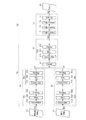
図6は、本実施形態に係るCNN処理部1bが用いる畳み込みニューラルネットワークの構成の一例を示す図である。
FIG. 6 is a diagram showing an example of the configuration of the convolutional neural network used by the
本実施形態に係る畳み込みニューラルネットワークは、明視野画像入力部10、蛍光画像入力部20、明視野画像処理部30、蛍光画像処理部40、連結部50、統合処理部60、識別部70、及び出力部80を含んで構成される。
The convolutional neural network according to the present embodiment includes a bright-field
そして、本実施形態に係る畳み込みニューラルネットワークは、明視野画像処理部30、蛍光画像処理部40、連結部50、及び統合処理部60によって上記した特徴抽出部Naを構成し、識別部70によって上記した識別部Nbを構成する。
Then, in the convolutional neural network according to the present embodiment, the bright field
尚、畳み込みニューラルネットワークの明視野画像処理部30、蛍光画像処理部40、統合処理部60、及び識別部70等のネットワークパラメータ(重み係数、バイアス)は、明視野画像と蛍光画像とに基づいて、細胞の状態等の識別結果を出力し得るように、学習部1cによって予め学習処理が実行される。
The network parameters (weighting coefficient, bias) of the convolutional neural network such as the bright field
[明視野画像入力部]
明視野画像入力部10は、明視野画像のデータD1(以下、「明視野画像D1」と称する)を取得し、明視野画像処理部30に出力する。
[Bright field image input section]
The bright-field
尚、明視野画像入力部10は、明視野画像D1に対してRGBの3チャンネルの色空間に分解する等の前処理を施した後に、当該明視野画像D1を明視野画像処理部30に出力する。
The bright-field
[蛍光画像入力部]
蛍光画像入力部20は、蛍光画像のデータD2(以下、「蛍光画像D2」と称する)を取得し、蛍光画像処理部40に出力する。
[Fluorescent image input unit]
The fluorescence
蛍光画像入力部20は、この際、明視野画像で撮像した領域と同一の領域を撮像した蛍光画像を取得する。より好適には、蛍光画像入力部20は、結像中心点及び拡大サイズが明視野画像と同一の条件下で撮像された蛍光画像を用いる。但し、撮像対象の細胞領域に目印等を付して、両画像の対応関係を識別可能にしておけば、明視野画像と蛍光画像との間で、撮像位置や拡大サイズが異なっていてもよい。
At this time, the fluorescence
尚、蛍光画像入力部20は、蛍光画像D2に対して2値化処理等の前処理を施した後に、当該蛍光画像D2を蛍光画像処理部40に出力しもよい。
The fluorescence
[明視野画像処理部]
明視野画像処理部30は、階層的に接続された特徴量抽出層(以下、「第1の特徴量抽出層列」とも称する)によって、明視野画像D1の画像特徴を抽出した複数の特徴マップのデータD3(以下、「第1の特徴マップ群D3」とも称する)を生成し、連結部50に出力する。
[Bright field image processing unit]
The bright-field
明視野画像処理部30は、図5を参照して説明した一般的なCNNと同様の構成を有し、複数の特徴量抽出層30a・・30n(任意の層数を表す)が階層的に接続されて構成されている。そして、明視野画像処理部30は、各特徴量抽出層30a・・30nにおいて、前階層から入力される入力データに対して畳み込み演算等の特徴量抽出処理を施して、特徴マップとして次階層に対して出力する。
The bright-field
各特徴量抽出層30a・・30nは、それぞれ、畳み込み層31a・・31n(図6中では、Convolutionと表す)、活性化層32a・・32n(図6中では、Reluと表す)、及びプーリング層33a・・33n(図6中では、Poolingと表す)を含んで構成される。尚、畳み込み層31a・・31n、活性化層32a・・32n、及びプーリング層33a・・33nが行う処理は、図5を参照して説明した処理と同様であるから、ここでの説明は省略する(後述する畳み込み層41a・・41k、活性化層42a・・42k、プーリング層43a・・43k、畳み込み層61a・・、活性化層62a・・、プーリング層63a・・についても同様)。
Each
明視野画像処理部30の特徴量抽出層30a・・30nの階層数や各特徴量抽出層30a・・30nに設定される特徴抽出フィルターの枚数は、識別対象(画像に映る細胞の種別、形態若しくは分布、又は、当該細胞内の生体物質の種別、形態若しくは分布等)に応じて、適宜設定される。但し、これらは、少なくとも明視野画像から個々の細胞の存在領域を識別し得るように、設定されるのが望ましい。
The number of layers of the feature
明視野画像処理部30は、このように、複数の階層的の特徴量抽出層30a・・30nにおける処理を繰り返すことで、明視野画像に含まれる複数の観点の特徴量(例えば、エッジ、領域、分布等)を高次元に抽出していき、その結果(第1の特徴マップ群D3)を連結部50に出力する。
The bright-field
[蛍光画像処理部]
蛍光画像処理部40は、階層的に接続された特徴量抽出層40a・・40k(以下、「第2の特徴量抽出層列」とも称する)によって、蛍光画像D2の画像特徴を抽出した複数の特徴マップのデータD4(以下、「第2の特徴マップ群D4」とも称する)を生成し、連結部50に出力する。
[Fluorescent image processing unit]
The fluorescent
蛍光画像処理部40は、図5を参照して説明した一般的なCNNと同様の構成を有し、複数の特徴量抽出層40a・・40k(任意の層数を表す)が階層的に接続されて構成されている。そして、蛍光画像処理部40は、各特徴量抽出層40a・・40kにおいて、前階層から入力される入力データに対して畳み込み演算等の特徴量抽出処理を施して、特徴マップとして次階層に対して出力する。
The fluorescence
各特徴量抽出層40a・・40kは、図5を参照して説明した一般的なCNNと同様に、畳み込み層41a・・41k、活性化層42a・・42k、及びプーリング層43a・・43kを含んで構成される。
Each feature
蛍光画像処理部40は、このように、複数の階層的の特徴量抽出層40a・・40kにおける処理を繰り返すことで、蛍光画像に含まれる複数の観点の特徴量(例えば、エッジ、領域、分布等)を高次元に抽出していき、その結果(第2の特徴マップ群D4)を連結部50に出力する。
The fluorescence
尚、蛍光画像処理部40の特徴量抽出層40a・・40kの階層数や各特徴量抽出層40a・・40kに設定される特徴抽出フィルターの枚数は、識別対象(画像に映る細胞の種別、形態若しくは分布、又は、当該細胞内の生体物質の種別、形態若しくは分布等)に応じて、適宜設定される。但し、これらは、少なくとも蛍光画像から蛍光輝点の集合状態を識別し得るように、設定されるのが望ましい。
The number of layers of the feature
但し、本実施形態に係る蛍光画像処理部40の特徴量抽出層40a・・40kの階層数は、蛍光画像の一般的な画像特性を考慮して、明視野画像処理部30の特徴量抽出層30a・・30nの階層数よりも少なくなるように設定されている。
However, the number of layers of the feature
以下、蛍光画像処理部40の特徴量抽出層40a・・40kの階層数の設定方法について説明する。
Hereinafter, a method of setting the number of layers of the feature
図7は、特徴量抽出層40a・・40kの階層数が増加することによる特徴マップの変化について説明する図である。尚、図7では、図7A、図7B、図7C、図7Dの順に、プーリング処理の回数が多くなったときの特徴マップ内の蛍光輝点Tのサイズを表している。
FIG. 7 is a diagram illustrating a change in the feature map due to an increase in the number of layers of the feature
本実施形態に係る蛍光画像処理部40は、上記したように、各特徴量抽出層40a・・40kにおいてプーリング処理を実行する。プーリング処理は、所定サイズの画素の領域(例えば、2×2画素)を一画素に圧縮する処理であり、一般に、CNNでは、かかる処理によって画像に映る物体の位置や回転等の変化に対して頑健性を持たせる。しかしながら、特徴量抽出層40a・・40kを過剰に多層に積み重ね、プーリング処理を繰り返し実行した場合、蛍光画像の特徴マップ内の蛍光輝点は、サイズが徐々に圧縮されていき、連結部50に出力する際には消失してしまうおそれがある。
As described above, the fluorescence
かかる観点から、本実施形態に係る蛍光画像処理部40の特徴量抽出層40a・・40kの階層数は、蛍光画像の画像特性(ここでは、蛍光輝点の典型サイズ)に基づいて、連結部50に出力する第2の特徴マップ群D4において、蛍光輝点のサイズが一画素以下のサイズにならないように設定する。
From this point of view, the number of layers of the feature
尚、蛍光画像の蛍光輝点の典型サイズは、細胞の種別、蛍光試薬の種別、及び撮像時の拡大サイズ等に応じて、概ね一定であり、複数の蛍光画像を参照したときに算出される蛍光輝点の平均サイズ等に基づいて、特徴量抽出層40a・・40kの階層数を設定すればよい。
The typical size of the fluorescence bright spot of the fluorescence image is substantially constant according to the type of cell, the type of fluorescence reagent, the enlarged size at the time of imaging, and the like, and is calculated when a plurality of fluorescence images are referred to. The number of layers of the feature
又、蛍光画像処理部40の特徴量抽出層40a・・40kの階層数は、より好適には、蛍光画像の画像特性(ここでは、蛍光輝点の典型的な分布)に基づいて、連結部50に出力する第2の特徴マップ群D4において、蛍光輝点が画像全体に占める画像領域が所定以上(例えば、特徴マップの全体のうちの3割以上)にならないように設定する。このように設定する理由としては、入力される蛍光画像に占める蛍光輝点の割合が多い場合、プーリング処理を繰り返し実行することによって、第2の特徴マップ群D4の画像全体に占める蛍光輝点の画像領域が過度に大きくなり、後段の処理が不可能となるためである。
Further, the number of layers of the feature
[連結部]
連結部50は、明視野画像処理部30が生成した第1の特徴マップ群D3と蛍光画像処理部40が生成した第2の特徴マップ群D4とを連結し、統合処理部60に出力する。
[Connecting part]
The connecting
連結部50は、例えば、明視野画像の第1の特徴マップ群D3と蛍光画像の第2の特徴マップ群D4を異なるチャンネルとして連結する。連結部50は、例えば、第1の特徴マップ群D3の特徴マップ数が100、第2の特徴マップ群D4の特徴マップ数が150であれば、これらを連結して、250の特徴マップとする。尚、連結部50の処理によって、第1の特徴マップ群D3と第2の特徴マップ群D4の間で画素領域毎の対応付けが行われることになる。
The connecting
但し、連結部50は、より好適には、第1の特徴マップ群D3と第2の特徴マップ群D4の間で特徴マップの画像サイズをあわせて、後段の統合処理部60に出力する。明視野画像処理部30と蛍光画像処理部40とは、上記したように、特徴量抽出層の階層数が異なるため、第1の特徴マップ群D3の画像サイズと、第2の特徴マップ群D4の画像サイズとは異なっている。そのため、仮に、両者のサイズ合わせを行わなければ、後段の統合処理部60は、第1の特徴マップ群D3と第2の特徴マップ群D4の画素領域毎の対応付けを行うことができないおそれがある。
However, more preferably, the connecting
かかる観点から、連結部50は、例えば、逆畳み込み(Deconvolution)やバイオニア補間等を用いて、第1の特徴マップ群D3の画像サイズを第2の特徴マップ群D4の画像サイズにアップスケーリングすることによって、第1の特徴マップ群D3と第2の特徴マップ群D4の間で特徴マップの画像サイズをあわせる。これによって、第1の特徴マップ群D3と第2の特徴マップ群D4の画素領域毎の対応付けが行われ、後段の処理の精度を向上させることができる。
From this point of view, the connecting
[統合処理部]
統合処理部60は、連結部50から出力される第1の特徴マップ群D3及び第2の特徴マップ群D4を取得して、階層的に接続された特徴量抽出層60・・(以下、「第3の特徴量抽出層列」とも称する)によって、再度、特徴抽出処理を実行する。そして、統合処理部60は、複数の特徴マップのデータD5(以下、「第3の特徴マップ群D3」とも称する)を生成し、識別部70に出力する。
[Integrated processing unit]
The
統合処理部60は、複数の特徴量抽出層60a・・ (任意の層数を表す)が階層的に接続されて構成されている。そして、各特徴量抽出層60a・・は、畳み込み層61a・・、活性化層62a・・、及びプーリング層63a・・を含んで構成される。尚、各特徴量抽出層60a・・は、第1の特徴マップ群D3及び第2の特徴マップ群D4の両方を入力画像として、当該第1の特徴マップ群D3及び第2の特徴マップ群D4から統合的に特徴抽出処理を実行する。
The
統合処理部60の特徴量抽出層60a・・の階層数や各特徴量抽出層60a・・に設定される特徴抽出フィルターの枚数は、識別対象(画像に映る細胞の種別、形態若しくは分布、又は、当該細胞内の生体物質の種別、形態若しくは分布等)に応じて、適宜設定される。但し、これらは、少なくとも明視野画像の特徴と蛍光画像の特徴の連関性を抽出し得るように設定されるのが望ましい。
The number of layers of the feature
[識別部]
識別部70は、統合処理部60から出力される第3の特徴マップ群D5に基づいて、明視野画像及び蛍光画像に映る細胞に係る識別情報D6を生成し、出力部80に対して出力する。
[Identification unit]
The
識別部70は、例えば、階層的に接続された三層の全結合層(図6中では、Fully Connectと表す)71、72、73と、出力層(図6中では、Softmaxと表す)74と、を含んで構成される。
The
本実施形態に係る識別部70の構成は、一般的なCNNの識別部Nbと同様の構成を有する。入力側の全結合層71は、統合処理部60から取得した第3の特徴マップ群D5の各値(各画素の画素値)に全結合し、その結合結果に対して重み係数を異ならせながら積和演算を行って、次階層の全結合層72に対して出力する。そして、次階層の全結合層72は、前階層の全結合層71の各素子が出力する値に全結合し、その結合結果に対して重み係数を異ならせながら積和演算を行って次階層の全結合層73に対して出力する。又、次階層の全結合層73は、前階層の全結合層72の各素子が出力する値に全結合し、その結合結果に対して重み係数を異ならせながら積和演算を行って、出力層74に出力する。
The configuration of the
出力側の全結合層73は、明視野画像及び蛍光画像に映る細胞に係る識別情報を出力する。全結合層73は、例えば、画素領域毎に出力素子を有し、画素領域毎に個々の細胞の種別(細胞種別A、細胞種別B、細胞種別C・・・等の数十カテゴリー)それぞれのいずれに属するかについての信頼度を出力する。
The fully connected
出力層74は、図5を参照して上記した一般的なCNNと同様に、例えば、全結合層73の各素子の出力値に対して、ソフトマックス関数を適用して、識別対象を確率として出力する。
In the output layer 74, in the same manner as the general CNN described above with reference to FIG. 5, for example, a softmax function is applied to the output value of each element of the fully coupled
識別部70の全結合層71、72、73の階層数や、全結合層72、73に設定される素子数は、識別対象(画像に映る細胞の種別、形態若しくは分布、又は、当該細胞内の生体物質の種別、形態若しくは分布等)に応じて、適宜設定される。但し、これらは、少なくとも個々の細胞の境界(例えば、細胞壁)を識別し、個々の細胞の存在領域について識別すると共に、複数の細胞が重なった状態で撮像された領域については、当該重なり領域を識別可能に設定されるのが望ましい。
The number of layers of the fully
尚、識別部70の構成は、識別対象、演算処理の際の処理負荷等を考慮して、種々に設計変更することができる。識別部70は、例えば、多層パーセプトロンに代えて、逆畳み込み処理を行う逆畳み込み部によって構成されてもよい(詳細は非特許文献1を参照されたい)。又、識別部70は、SVM(Support Vector Machine)等によって、構成されてもよい。
The configuration of the
[出力部]
出力部80(図6中では、Resultと表す)は、識別部70から出力される識別情報D6を取得して、例えば、当該識別情報D6に基づいて、確率が最大のカテゴリーを最終的な識別結果として選択して、出力する。尚、表示装置3には、出力部80が出力する識別結果が、細胞に係る識別情報として表示される。
[Output section]
The output unit 80 (represented as Result in FIG. 6) acquires the identification information D6 output from the
図8は、細胞に係る識別情報の表示態様の一例を示す図である。 FIG. 8 is a diagram showing an example of a display mode of identification information relating to cells.
図8において、Rの領域は明視野画像の全体領域、R1の領域は細胞Aの領域、R2の領域は細胞Bの領域、R3の領域は細胞Cの領域、及びR4の領域は細胞Bと細胞Aの重なり領域を示す。尚、領域R1〜R4は、例えば、異なる色に色分けされて表示される。 In FIG. 8, the region of R is the entire region of the bright-field image, the region of R1 is the region of cell A, the region of R2 is the region of cell B, the region of R3 is the region of cell C, and the region of R4 is cell B. The overlapping region of cell A is shown. The areas R1 to R4 are displayed in different colors, for example.
図8に示すように、出力部80は、例えば、明視野画像Rに映る複数の細胞を各別に識別すると共に、当該明視野画像内におけるそれぞれの細胞(ここでは、細胞A、細胞B、細胞C)の領域を画素領域毎に識別し、その結果を出力する。そして、出力部80は、複数の細胞が重なった状態で撮像された領域R4については、当該重なり領域を識別可能に構成している。これによって、細胞毎の状態をより明確に識別することが可能となる。 As shown in FIG. 8, the output unit 80 identifies, for example, a plurality of cells reflected in the bright-field image R, and each cell (here, cell A, cell B, and cell) in the bright-field image. The area of C) is identified for each pixel area, and the result is output. Then, the output unit 80 is configured so that the overlapping region can be identified with respect to the region R4 imaged in a state where a plurality of cells are overlapped. This makes it possible to more clearly identify the state of each cell.
[学習部]
以上のように説明した畳み込みニューラルネットワーク(明視野画像処理部30、蛍光画像処理部40、統合処理部60、識別部70)は、学習部1cによって機械学習が実行されたものが用いられる。
[Learning Department]
As the convolutional neural network described above (bright-field
学習部1cは、例えば、同一領域を撮像した明視野画像及び蛍光画像と、これらの正解カテゴリーが関連付けられたデータを教師データとして用いて、明視野画像処理部30、蛍光画像処理部40、統合処理部60、識別部70のネットワークパラメータ(例えば、重み係数、バイアス)を調整する。
The learning unit 1c integrates the bright-field
学習部1cは、例えば、同一領域を撮像した明視野画像及び蛍光画像と、これらの正解カテゴリーが関連付けられた教師データを用いて、正解に対する出力データ(ここでは、識別部70の出力)の誤差分を示す損失が小さくなるように、明視野画像処理部30、蛍光画像処理部40、統合処理部60、識別部70のネットワークパラメータ(例えば、重み係数、バイアス)を調整することによって、かかる学習処理を実行することができる。尚、当該損失は、例えば、softmax cross entropy関数等を用いて、表すことができる。
The learning unit 1c uses, for example, a bright-field image and a fluorescent image obtained by capturing the same region and teacher data in which these correct answer categories are associated with each other, and the error of the output data (here, the output of the identification unit 70) with respect to the correct answer. Such learning is performed by adjusting the network parameters (for example, weighting coefficient, bias) of the bright-field
学習部1cは、例えば、公知の誤差逆伝搬法等を用いて、これらの学習処理を行えばよい。そして、学習部1cは、学習処理によって調整したネットワークパラメータを記憶部(例えば、外部記憶装置104)に格納する。 The learning unit 1c may perform these learning processes by using, for example, a known error back propagation method or the like. Then, the learning unit 1c stores the network parameters adjusted by the learning process in the storage unit (for example, the external storage device 104).
尚、教師データとして、明視野画像及び蛍光画像に対して画素領域毎の正解カテゴリーを付したデータを用いることによって、図8に示したように、画素領域毎の識別結果を出力することが可能である。 As the teacher data, it is possible to output the identification result for each pixel region as shown in FIG. 8 by using the data in which the correct answer category for each pixel region is attached to the bright field image and the fluorescent image. Is.
以上のように、本実施形態に係る画像処理装置1によれば、同一の細胞領域を撮像した明視野画像と蛍光画像を用いて、畳み込みニューラルネットワークによる処理を行うことで、細胞に係る種々の識別情報を生成することができる。特に、本実施形態に係る畳み込みニューラルネットワークは、明視野画像処理部30と蛍光画像処理部40とによって、明視野画像と蛍光画像のそれぞれの画像特性に適合した特徴抽出処理を実行し、その後、統合処理部60で統合的に特徴抽出処理を行う。従って、本実施形態に係る画像処理装置1は、明視野画像又は蛍光画像の一方だけでは識別できないような細胞の種々の状態を識別することが可能である。
As described above, according to the
(その他の実施形態)
本発明は、上記実施形態に限らず、種々に変形態様が考えられる。
(Other embodiments)
The present invention is not limited to the above embodiment, and various modifications can be considered.
尚、上記実施形態で示した畳み込みニューラルネットワークの構成は、一例であって、識別対象や処理負荷等を考慮して、種々に設計変更可能である。例えば、特徴抽出を行う際に、所定領域毎に、特徴抽出処理を行って、これらを統合する方式を用いてもよい。又、その他、特徴抽出を行う際に、更に、HOG特徴量抽出処理、シルエット抽出処理、領域分割処理、輝度勾配抽出処理、動き抽出処理、形状モデルフィッティング又はこれらの組み合わせ等を用いてもよい。 The configuration of the convolutional neural network shown in the above embodiment is an example, and the design can be changed in various ways in consideration of the identification target, the processing load, and the like. For example, when performing feature extraction, a method may be used in which feature extraction processing is performed for each predetermined region and these are integrated. In addition, when performing feature extraction, HOG feature amount extraction processing, silhouette extraction processing, region division processing, luminance gradient extraction processing, motion extraction processing, shape model fitting, or a combination thereof and the like may be further used.
又、当該畳み込みニューラルネットワークは、細胞毎の抗体反応の定量等を行うべく、個々の細胞内に含まれる蛍光輝点の数等を出力する態様であってもよい。 Further, the convolutional neural network may be in a mode of outputting the number of fluorescent bright spots contained in each cell in order to quantify the antibody reaction for each cell.
以上、本発明の具体例を詳細に説明したが、これらは例示にすぎず、請求の範囲を限定するものではない。請求の範囲に記載の技術には、以上に例示した具体例を様々に変形、変更したものが含まれる。 Although specific examples of the present invention have been described in detail above, these are merely examples and do not limit the scope of claims. The techniques described in the claims include various modifications and modifications of the specific examples illustrated above.
本開示に係る画像処理装置によれば、CNNを用いて、画像内の細胞に係る種々の識別情報を生成することができる。 According to the image processing apparatus according to the present disclosure, various identification information related to cells in an image can be generated by using CNN.
U 細胞認識システム
1 画像処理装置
2 撮像装置
3 表示装置
4 通信ネットワーク
1a 画像取得部
1b CNN処理部
1c 学習部
10 明視野画像入力部
20 蛍光画像入力部
30 明視野画像処理部
40 蛍光画像処理部
50 連結部
60 統合処理部
70 識別部
80 出力部
U
Claims (13)
畳み込みニューラルネットワークを用いて、前記明視野画像及び前記蛍光画像の画像特徴を抽出して、前記細胞に係る識別情報を出力するCNN処理部と、
を備える、画像処理装置であって、
前記畳み込みニューラルネットワークは、
階層的に接続された第1の特徴量抽出層列により、前記明視野画像の画像特徴を抽出して、第1の特徴マップ群を生成する明視野画像処理部と、
階層的に接続された第2の特徴量抽出層列により、前記蛍光画像の画像特徴を抽出して、第2の特徴マップ群を生成する蛍光画像処理部と、
前記第1の特徴マップ群と前記第2の特徴マップ群を連結する連結部と、
階層的に接続された第3の特徴量抽出層列により、前記連結部で連結された前記第1及び第2の特徴マップ群の画像特徴を抽出して、第3の特徴マップ群を生成する統合処理部と、
前記第3の特徴マップ群に基づいて、前記細胞に係る識別情報を生成する識別部と、
を有する、画像処理装置。 An image acquisition unit that acquires a bright-field image of cells in a bright field and a fluorescence image of a fluorescence bright spot of a fluorescent reagent dropped in a region containing the cells.
Using a convolutional neural network, a CNN processing unit that extracts image features of the bright-field image and the fluorescence image and outputs identification information related to the cells, and a CNN processing unit.
An image processing device equipped with
The convolutional neural network
A bright-field image processing unit that extracts image features of the bright-field image from the first feature-quantity sampling layer sequence that is hierarchically connected to generate a first feature map group, and a bright-field image processing unit.
A fluorescence image processing unit that extracts the image features of the fluorescence image by the second feature amount sampling layer sequence that is hierarchically connected to generate a second feature map group, and
A connecting portion that connects the first feature map group and the second feature map group, and
The image features of the first and second feature map groups connected by the connecting portion are extracted from the hierarchically connected third feature amount extraction layer sequence to generate a third feature map group. Integrated processing unit and
Based on the third feature map group, an identification unit that generates identification information related to the cell, and an identification unit.
An image processing device.
請求項1に記載の画像処理装置。 The identification information relating to the cell includes information relating to the type, morphology, or distribution of the cell, or the type, morphology, or distribution of the biological substance contained in the cell.
The image processing apparatus according to claim 1.
請求項1又は2に記載の画像処理装置。 The identification unit generates identification information relating to the cell in association with each pixel region of the bright-field image or the fluorescence image.
The image processing apparatus according to claim 1 or 2.
前記識別部は、前記明視野画像又は前記蛍光画像に映る複数の前記細胞の各々について、前記細胞に係る識別情報を生成する、
請求項1乃至3のいずれか一項に記載の画像処理装置。 When there are a plurality of the cells reflected in the bright field image or the fluorescence image,
The identification unit generates identification information relating to the cells for each of the plurality of cells displayed in the bright field image or the fluorescence image.
The image processing apparatus according to any one of claims 1 to 3.
請求項1乃至4のいずれか一項に記載の画像処理装置。 The connecting portion connects the first feature map group and the second feature map group according to the image size.
The image processing apparatus according to any one of claims 1 to 4.
請求項1乃至5のいずれか一項に記載の画像処理装置。 The number of layers of the second feature amount extraction layer row is smaller than the number of layers of the first feature amount extraction layer row.
The image processing apparatus according to any one of claims 1 to 5.
請求項1乃至6のいずれか一項に記載の画像処理装置。 The number of layers of the second feature amount extraction layer row is based on the image characteristics of the fluorescent image determined according to the type of the cell or the biological substance in the cell, the type of the fluorescent reagent, and the enlarged size at the time of imaging. Is set,
The image processing apparatus according to any one of claims 1 to 6.
請求項7に記載の画像処理装置。 The number of layers of the second feature amount extraction layer row is determined by the size of each fluorescent bright spot in the second feature map group based on the typical size of the fluorescent bright spots on the image characteristics of the fluorescent image. Set not to be less than the size,
The image processing apparatus according to claim 7.
請求項8に記載の画像処理装置。 The typical size of the fluorescent bright spots on the image characteristics of the fluorescent image is the average size of the fluorescent bright spots observed in the plurality of the fluorescent images.
The image processing apparatus according to claim 8.
請求項8又は9に記載の画像処理装置。 The predetermined size is one pixel.
The image processing apparatus according to claim 8 or 9.
請求項1乃至10のいずれか一項に記載の画像処理装置。 The number of layers of the second feature amount extraction layer row is the region ratio of the fluorescent bright spots to the entire image in the second feature map group based on the typical distribution of the fluorescent bright spots on the image characteristics of the fluorescent image. Is set so that it does not exceed the specified value,
The image processing apparatus according to any one of claims 1 to 10.
畳み込みニューラルネットワークを用いて、前記明視野画像及び前記蛍光画像の画像特徴を抽出して、前記細胞に係る識別情報を出力する画像処理方法であって、
前記畳み込みニューラルネットワークは、
階層的に接続された第1の特徴量抽出層列により、前記明視野画像の画像特徴を抽出して、第1の特徴マップ群を生成し、
階層的に接続された第2の特徴量抽出層列により、前記蛍光画像の画像特徴を抽出して、第2の特徴マップ群を生成し、
前記第1の特徴マップ群と前記第2の特徴マップ群を連結し、
階層的に接続された第3の特徴量抽出層列により、連結された前記第1及び第2の特徴マップ群の画像特徴を抽出して、第3の特徴マップ群を生成し、
前記第3の特徴マップ群に基づいて、前記細胞に係る識別情報を生成する、画像処理方法。 A bright-field image of cells in a bright field and a fluorescence image of a fluorescence bright spot of a fluorescent reagent dropped on the region containing the cells were acquired.
An image processing method that extracts image features of the bright-field image and the fluorescence image using a convolutional neural network and outputs identification information related to the cells.
The convolutional neural network
The image features of the bright-field image are extracted from the first feature quantity extraction layer sequence connected hierarchically to generate a first feature map group.
The image features of the fluorescence image are extracted by the second feature amount extraction layer column connected hierarchically to generate a second feature map group.
The first feature map group and the second feature map group are connected to each other.
The third feature amount extraction layer sequence which is hierarchically connected, by extracting the image feature of the connected first and second characteristics map group to generate a third feature map groups,
An image processing method that generates identification information related to the cells based on the third feature map group.
細胞を明視野で撮像した明視野画像、及び前記細胞を含む領域に滴下された蛍光試薬の蛍光輝点を撮像した蛍光画像を取得する処理と、
畳み込みニューラルネットワークを用いて、前記明視野画像及び前記蛍光画像の画像特徴を抽出して、前記細胞に係る識別情報を出力する処理と、
を実行させる、画像処理プログラムであって、
前記畳み込みニューラルネットワークは、
階層的に接続された第1の特徴量抽出層列により、前記明視野画像の画像特徴を抽出して、第1の特徴マップ群を生成する処理と、
階層的に接続された第2の特徴量抽出層列により、前記蛍光画像の画像特徴を抽出して、第2の特徴マップ群を生成する処理と、
前記第1の特徴マップ群と前記第2の特徴マップ群を連結する処理と、
階層的に接続された第3の特徴量抽出層列により、連結された前記第1及び第2の特徴マップ群の画像特徴を抽出して、第3の特徴マップ群を生成する処理と、
前記第3の特徴マップ群に基づいて、前記細胞に係る識別情報を生成する処理と、有する、画像処理プログラム。
On the computer
A process of acquiring a bright-field image of cells in a bright field and a fluorescence image of a fluorescence bright spot of a fluorescent reagent dropped in a region containing the cells.
A process of extracting the image features of the bright field image and the fluorescent image using a convolutional neural network and outputting identification information related to the cells.
Is an image processing program that executes
The convolutional neural network
A process of extracting the image features of the bright-field image from the first feature quantity sampling layer sequence connected hierarchically to generate a first feature map group, and a process of generating the first feature map group.
A process of extracting the image features of the fluorescence image by the second feature quantity sampling layer sequence connected hierarchically to generate a second feature map group, and
The process of connecting the first feature map group and the second feature map group, and
The third feature amount extraction layer sequence which is hierarchically connected, a process of extracting the image feature of the connected first and second characteristics map group, to produce a third characteristic map groups,
An image processing program having a process of generating identification information related to the cell based on the third feature map group.
Priority Applications (2)
| Application Number | Priority Date | Filing Date | Title |
|---|---|---|---|
| JP2017074642A JP6915349B2 (en) | 2017-04-04 | 2017-04-04 | Image processing equipment, image processing method, and image processing program |
| US15/944,211 US10692209B2 (en) | 2017-04-04 | 2018-04-03 | Image processing apparatus, image processing method, and computer-readable non-transitory recording medium storing image processing program |
Applications Claiming Priority (1)
| Application Number | Priority Date | Filing Date | Title |
|---|---|---|---|
| JP2017074642A JP6915349B2 (en) | 2017-04-04 | 2017-04-04 | Image processing equipment, image processing method, and image processing program |
Publications (2)
| Publication Number | Publication Date |
|---|---|
| JP2018180635A JP2018180635A (en) | 2018-11-15 |
| JP6915349B2 true JP6915349B2 (en) | 2021-08-04 |
Family
ID=63670627
Family Applications (1)
| Application Number | Title | Priority Date | Filing Date |
|---|---|---|---|
| JP2017074642A Active JP6915349B2 (en) | 2017-04-04 | 2017-04-04 | Image processing equipment, image processing method, and image processing program |
Country Status (2)
| Country | Link |
|---|---|
| US (1) | US10692209B2 (en) |
| JP (1) | JP6915349B2 (en) |
Families Citing this family (35)
| Publication number | Priority date | Publication date | Assignee | Title |
|---|---|---|---|---|
| WO2018231204A1 (en) | 2017-06-13 | 2018-12-20 | Google Llc | Augmented reality microscope for pathology |
| WO2018229594A1 (en) * | 2017-06-14 | 2018-12-20 | 株式会社半導体エネルギー研究所 | Imaging device and electronic device |
| JP6805984B2 (en) * | 2017-07-06 | 2020-12-23 | 株式会社デンソー | Convolutional neural network |
| SE542402C2 (en) * | 2018-07-02 | 2020-04-21 | Cellavision Ab | Method and apparatus for training a neural network classifier to classify an image depicting one or more objects of a biological sample |
| JP7228031B2 (en) * | 2018-10-15 | 2023-02-22 | ベンタナ メディカル システムズ, インコーポレイテッド | Systems and methods for cell sorting |
| TWI717655B (en) * | 2018-11-09 | 2021-02-01 | 財團法人資訊工業策進會 | Feature determination apparatus and method adapted to multiple object sizes |
| CN111414922B (en) * | 2019-01-07 | 2022-11-15 | 阿里巴巴集团控股有限公司 | Feature extraction method, image processing method, model training method and device |
| EP3712618B1 (en) * | 2019-03-18 | 2023-10-04 | Euroimmun Medizinische Labordiagnostika AG | Method for detecting a binding of antibodies of a patient sample to double-stranded dna using crithidia luciliae cells and fluorescence microscopy |
| US11783917B2 (en) | 2019-03-21 | 2023-10-10 | Illumina, Inc. | Artificial intelligence-based base calling |
| US11210554B2 (en) | 2019-03-21 | 2021-12-28 | Illumina, Inc. | Artificial intelligence-based generation of sequencing metadata |
| JP7362284B2 (en) * | 2019-03-29 | 2023-10-17 | キヤノン株式会社 | Image processing method, image processing device, program, image processing system, and learned model manufacturing method |
| BR112021019977A2 (en) | 2019-04-11 | 2021-12-07 | Agilent Technologies Inc | User interface configured to facilitate user annotation for instance segmentation within biological sample |
| JP7482894B2 (en) * | 2019-04-12 | 2024-05-14 | インベニオ イメージング、インコーポレイテッド | Imaging system for detection of intraoperative contrast agents in tissue - Patents.com |
| US11132772B2 (en) | 2019-06-11 | 2021-09-28 | Samsung Electronics Co., Ltd. | Asymmetric normalized correlation layer for deep neural network feature matching |
| JP7385241B2 (en) * | 2019-06-19 | 2023-11-22 | 国立大学法人 東京大学 | Image extraction device, image extraction system, image extraction method, and image extraction program |
| US20240125700A1 (en) * | 2019-10-14 | 2024-04-18 | University Of Southern California | Systems, methods and assays for outlier clustering unsupervised learning automated report (ocular) |
| CN110751160B (en) * | 2019-10-30 | 2022-09-13 | 华中科技大学 | Method, device and system for detecting object in image |
| WO2021096152A1 (en) * | 2019-11-15 | 2021-05-20 | Samsung Electronics Co., Ltd. | Asymmetric normalized correlation layer for deep neural network feature matching |
| CN111147760B (en) * | 2019-12-23 | 2021-08-24 | 兴科迪智能科技(北京)有限公司 | Light field camera, luminosity adjusting method and device thereof and electronic equipment |
| CN111103275B (en) * | 2019-12-24 | 2021-06-01 | 电子科技大学 | PAT Prior Information Aided Dynamic FMT Reconstruction Method Based on CNN and Adaptive EKF |
| JP6737491B1 (en) * | 2020-01-09 | 2020-08-12 | 株式会社アドイン研究所 | Diagnostic device, diagnostic system and program using AI |
| JP7711402B2 (en) * | 2020-03-30 | 2025-07-23 | 東ソー株式会社 | Discrimination method using deep learning |
| WO2021199709A1 (en) * | 2020-03-31 | 2021-10-07 | 富士フイルム株式会社 | Cell culture evaluation device, operation method for cell culture evaluation device, and operation program for cell culture evaluation device |
| WO2021229668A1 (en) * | 2020-05-12 | 2021-11-18 | 株式会社日立ハイテク | Nucleic acid analysis device, nucleic acid analysis method, and machine learning method |
| JP7354063B2 (en) * | 2020-05-14 | 2023-10-02 | 株式会社東芝 | Classification systems, programs and learning systems |
| KR20230110248A (en) * | 2020-09-08 | 2023-07-21 | 인시트로, 인코포레이티드 | Biological Image Transformation Using Machine Learning Models |
| CN114495096A (en) * | 2020-10-23 | 2022-05-13 | 上海交通大学医学院附属新华医院 | Method and device for acquiring cell classification model |
| CN112508909B (en) * | 2020-12-03 | 2023-08-25 | 中国人民解放军陆军军医大学第二附属医院 | Disease association method of peripheral blood cell morphology automatic detection system |
| US20220301657A1 (en) | 2021-03-16 | 2022-09-22 | Illumina, Inc. | Tile location and/or cycle based weight set selection for base calling |
| US20240185422A1 (en) * | 2021-04-19 | 2024-06-06 | Thrive Bioscience, Inc. | Plaque detection method and apparatus for imaging of cells |
| CN113408350B (en) * | 2021-05-17 | 2023-09-19 | 杭州电子科技大学 | A remote sensing image saliency detection method based on edge feature extraction |
| CN114152557B (en) * | 2021-11-16 | 2024-04-30 | 深圳元视医学科技有限公司 | Blood cell counting method and system based on image analysis |
| EP4320447A4 (en) * | 2022-04-12 | 2024-06-26 | Wyonics LLC | SYSTEMS, DEVICES AND METHODS FOR IDENTIFYING, COLLECTING, REPOSITIONING AND ANALYSIS OF PARTICLES IN THE MICROMETERS AND NANOMETER RANGE |
| EP4312190A1 (en) * | 2022-07-26 | 2024-01-31 | Leica Microsystems CMS GmbH | Fluorescence imaging and visualisation |
| CN117169093A (en) * | 2023-10-30 | 2023-12-05 | 深圳市明鉴检测专业技术有限公司 | Cell quantitative detection method based on fluorescent antibody labeling |
Family Cites Families (12)
| Publication number | Priority date | Publication date | Assignee | Title |
|---|---|---|---|---|
| JPH0212060A (en) * | 1988-06-30 | 1990-01-17 | Sumitomo Electric Ind Ltd | Method for apparatus for monitoring cell state |
| JPH0765161A (en) * | 1993-08-30 | 1995-03-10 | Nec Corp | Image processor |
| JP5660273B2 (en) * | 2010-01-04 | 2015-01-28 | 日本電気株式会社 | Image diagnosis method, image diagnosis apparatus, and image diagnosis program |
| JP5858461B2 (en) | 2011-03-17 | 2016-02-10 | コニカミノルタ株式会社 | Pathological diagnosis information generation method and pathological diagnosis information generation system |
| JP5892238B2 (en) * | 2012-03-30 | 2016-03-23 | コニカミノルタ株式会社 | Medical image processing apparatus and program |
| US20130338016A1 (en) * | 2012-04-17 | 2013-12-19 | Vala Sciences, Inc. | Method For Integrated Pathology Diagnosis And Digital Biomarker Pattern Analysis |
| JP6629762B2 (en) * | 2014-05-23 | 2020-01-15 | ベンタナ メディカル システムズ, インコーポレイテッド | Systems and methods for detection of biological structures and / or patterns in images |
| KR102130162B1 (en) * | 2015-03-20 | 2020-07-06 | 프라운호퍼 게젤샤프트 쭈르 푀르데룽 데어 안겐반텐 포르슝 에. 베. | Assignment of relevance scores for artificial neural networks |
| US9947102B2 (en) * | 2016-08-26 | 2018-04-17 | Elekta, Inc. | Image segmentation using neural network method |
| US10740651B2 (en) * | 2016-10-27 | 2020-08-11 | General Electric Company | Methods of systems of generating virtual multi-dimensional models using image analysis |
| US10410348B2 (en) * | 2016-12-21 | 2019-09-10 | Elekta, Inc. | Online learning enhanced atlas-based auto-segmentation |
| US10573003B2 (en) * | 2017-02-13 | 2020-02-25 | Amit Sethi | Systems and methods for computational pathology using points-of-interest |
-
2017
- 2017-04-04 JP JP2017074642A patent/JP6915349B2/en active Active
-
2018
- 2018-04-03 US US15/944,211 patent/US10692209B2/en active Active
Also Published As
| Publication number | Publication date |
|---|---|
| US20180286040A1 (en) | 2018-10-04 |
| US10692209B2 (en) | 2020-06-23 |
| JP2018180635A (en) | 2018-11-15 |
Similar Documents
| Publication | Publication Date | Title |
|---|---|---|
| JP6915349B2 (en) | Image processing equipment, image processing method, and image processing program | |
| US12008764B2 (en) | Systems, devices, and methods for image processing to generate an image having predictive tagging | |
| CN111524137B (en) | Cell identification counting method and device based on image identification and computer equipment | |
| US11776124B1 (en) | Transforming multispectral images to enhanced resolution images enabled by machine learning | |
| CN116580394B (en) | A method for leukocyte detection based on multi-scale fusion and deformable self-attention | |
| US10824847B2 (en) | Generating virtually stained images of unstained samples | |
| JP2022180419A (en) | Image analysis method, device, program, and method for manufacturing trained deep learning algorithm | |
| US9684960B2 (en) | Automated histological diagnosis of bacterial infection using image analysis | |
| EP2803015B1 (en) | Two stage categorization of objects in images | |
| KR101628276B1 (en) | System and method for pathological analysis based on cloud | |
| JP2021073566A (en) | Image processing systems and methods for displaying multiple images of biological specimen | |
| Khan et al. | Unsupervised identification of malaria parasites using computer vision | |
| EP2095094A2 (en) | Quantitative, multispectral image analysis of tissue specimens stained with quantum dots | |
| Juhong et al. | Super-resolution and segmentation deep learning for breast cancer histopathology image analysis | |
| JP4997255B2 (en) | Cell image analyzer | |
| Hu et al. | Automatic detection of tuberculosis bacilli in sputum smear scans based on subgraph classification | |
| CN116893162A (en) | Rare anti-nuclear antibody karyotype detection method based on YOLO and attention neural network | |
| WO2021157397A1 (en) | Information processing apparatus and information processing system | |
| CN118096788A (en) | Method and device for assigning image regions of an image sequence to result classes | |
| JP2005227097A (en) | Cell image analyzer | |
| Paul et al. | A review on computational methods based on machine learning and deep learning techniques for malaria detection | |
| Tran et al. | Protein crystallization segmentation and classification using subordinate color channel in fluorescence microscopy images | |
| Tran et al. | Classifying protein crystallization trial images using subordinate color channel | |
| Tran et al. | Mobile Fluorescence Imaging and Protein Crystal Recognition | |
| US12548157B2 (en) | Systems and methods for inline quality control of slide digitization |
Legal Events
| Date | Code | Title | Description |
|---|---|---|---|
| A521 | Request for written amendment filed |
Free format text: JAPANESE INTERMEDIATE CODE: A523 Effective date: 20171227 |
|
| RD02 | Notification of acceptance of power of attorney |
Free format text: JAPANESE INTERMEDIATE CODE: A7422 Effective date: 20190708 |
|
| RD04 | Notification of resignation of power of attorney |
Free format text: JAPANESE INTERMEDIATE CODE: A7424 Effective date: 20191011 |
|
| A621 | Written request for application examination |
Free format text: JAPANESE INTERMEDIATE CODE: A621 Effective date: 20200318 |
|
| A977 | Report on retrieval |
Free format text: JAPANESE INTERMEDIATE CODE: A971007 Effective date: 20210412 |
|
| A131 | Notification of reasons for refusal |
Free format text: JAPANESE INTERMEDIATE CODE: A131 Effective date: 20210420 |
|
| A521 | Request for written amendment filed |
Free format text: JAPANESE INTERMEDIATE CODE: A523 Effective date: 20210519 |
|
| TRDD | Decision of grant or rejection written | ||
| A01 | Written decision to grant a patent or to grant a registration (utility model) |
Free format text: JAPANESE INTERMEDIATE CODE: A01 Effective date: 20210615 |
|
| A61 | First payment of annual fees (during grant procedure) |
Free format text: JAPANESE INTERMEDIATE CODE: A61 Effective date: 20210628 |
|
| R150 | Certificate of patent or registration of utility model |
Ref document number: 6915349 Country of ref document: JP Free format text: JAPANESE INTERMEDIATE CODE: R150 |