JP6910872B2 - Gasification furnace equipment and gasification combined cycle equipment equipped with this - Google Patents
Gasification furnace equipment and gasification combined cycle equipment equipped with this Download PDFInfo
- Publication number
- JP6910872B2 JP6910872B2 JP2017138245A JP2017138245A JP6910872B2 JP 6910872 B2 JP6910872 B2 JP 6910872B2 JP 2017138245 A JP2017138245 A JP 2017138245A JP 2017138245 A JP2017138245 A JP 2017138245A JP 6910872 B2 JP6910872 B2 JP 6910872B2
- Authority
- JP
- Japan
- Prior art keywords
- temperature
- gas
- water supply
- flow path
- flow rate
- Prior art date
- Legal status (The legal status is an assumption and is not a legal conclusion. Google has not performed a legal analysis and makes no representation as to the accuracy of the status listed.)
- Active
Links
- 238000002309 gasification Methods 0.000 title claims description 137
- XLYOFNOQVPJJNP-UHFFFAOYSA-N water Substances O XLYOFNOQVPJJNP-UHFFFAOYSA-N 0.000 claims description 121
- 239000008400 supply water Substances 0.000 claims description 37
- 238000001514 detection method Methods 0.000 claims description 18
- OKTJSMMVPCPJKN-UHFFFAOYSA-N Carbon Chemical compound [C] OKTJSMMVPCPJKN-UHFFFAOYSA-N 0.000 claims description 8
- 229910052799 carbon Inorganic materials 0.000 claims description 8
- 239000004449 solid propellant Substances 0.000 claims description 8
- 238000001704 evaporation Methods 0.000 claims description 5
- 230000008020 evaporation Effects 0.000 claims description 5
- 239000007789 gas Substances 0.000 description 181
- 239000003245 coal Substances 0.000 description 58
- 238000011084 recovery Methods 0.000 description 14
- QGZKDVFQNNGYKY-UHFFFAOYSA-N Ammonia Chemical compound N QGZKDVFQNNGYKY-UHFFFAOYSA-N 0.000 description 12
- IJGRMHOSHXDMSA-UHFFFAOYSA-N Atomic nitrogen Chemical compound N#N IJGRMHOSHXDMSA-UHFFFAOYSA-N 0.000 description 12
- NLXLAEXVIDQMFP-UHFFFAOYSA-N Ammonia chloride Chemical compound [NH4+].[Cl-] NLXLAEXVIDQMFP-UHFFFAOYSA-N 0.000 description 8
- QVGXLLKOCUKJST-UHFFFAOYSA-N atomic oxygen Chemical compound [O] QVGXLLKOCUKJST-UHFFFAOYSA-N 0.000 description 8
- 230000007423 decrease Effects 0.000 description 8
- 239000001301 oxygen Substances 0.000 description 8
- 229910052760 oxygen Inorganic materials 0.000 description 8
- 238000010248 power generation Methods 0.000 description 8
- 230000007797 corrosion Effects 0.000 description 7
- 238000005260 corrosion Methods 0.000 description 7
- 238000000926 separation method Methods 0.000 description 7
- VEXZGXHMUGYJMC-UHFFFAOYSA-N Hydrochloric acid Chemical compound Cl VEXZGXHMUGYJMC-UHFFFAOYSA-N 0.000 description 6
- 229910021529 ammonia Inorganic materials 0.000 description 6
- 239000000567 combustion gas Substances 0.000 description 6
- 238000007670 refining Methods 0.000 description 6
- 238000010586 diagram Methods 0.000 description 5
- 239000000428 dust Substances 0.000 description 5
- 229910000041 hydrogen chloride Inorganic materials 0.000 description 5
- IXCSERBJSXMMFS-UHFFFAOYSA-N hydrogen chloride Substances Cl.Cl IXCSERBJSXMMFS-UHFFFAOYSA-N 0.000 description 5
- 229910052757 nitrogen Inorganic materials 0.000 description 5
- 238000000746 purification Methods 0.000 description 5
- 238000010521 absorption reaction Methods 0.000 description 4
- 235000019270 ammonium chloride Nutrition 0.000 description 4
- 239000002737 fuel gas Substances 0.000 description 4
- 239000000126 substance Substances 0.000 description 4
- 230000000694 effects Effects 0.000 description 3
- 239000000446 fuel Substances 0.000 description 3
- 239000011261 inert gas Substances 0.000 description 3
- 239000007800 oxidant agent Substances 0.000 description 3
- 239000002023 wood Substances 0.000 description 3
- XKRFYHLGVUSROY-UHFFFAOYSA-N Argon Chemical compound [Ar] XKRFYHLGVUSROY-UHFFFAOYSA-N 0.000 description 2
- CURLTUGMZLYLDI-UHFFFAOYSA-N Carbon dioxide Chemical compound O=C=O CURLTUGMZLYLDI-UHFFFAOYSA-N 0.000 description 2
- NINIDFKCEFEMDL-UHFFFAOYSA-N Sulfur Chemical compound [S] NINIDFKCEFEMDL-UHFFFAOYSA-N 0.000 description 2
- 238000007664 blowing Methods 0.000 description 2
- 239000003638 chemical reducing agent Substances 0.000 description 2
- 238000004140 cleaning Methods 0.000 description 2
- 230000006866 deterioration Effects 0.000 description 2
- 229910001873 dinitrogen Inorganic materials 0.000 description 2
- 230000006870 function Effects 0.000 description 2
- 239000012535 impurity Substances 0.000 description 2
- 239000007788 liquid Substances 0.000 description 2
- 238000000034 method Methods 0.000 description 2
- 238000012986 modification Methods 0.000 description 2
- 230000004048 modification Effects 0.000 description 2
- 238000003860 storage Methods 0.000 description 2
- 229910052717 sulfur Inorganic materials 0.000 description 2
- 239000011593 sulfur Substances 0.000 description 2
- 239000002699 waste material Substances 0.000 description 2
- 239000002028 Biomass Substances 0.000 description 1
- 241000196324 Embryophyta Species 0.000 description 1
- 241000209504 Poaceae Species 0.000 description 1
- 150000001412 amines Chemical class 0.000 description 1
- 229910052786 argon Inorganic materials 0.000 description 1
- 239000001569 carbon dioxide Substances 0.000 description 1
- 229910002092 carbon dioxide Inorganic materials 0.000 description 1
- 238000006243 chemical reaction Methods 0.000 description 1
- 239000013626 chemical specie Substances 0.000 description 1
- 238000009841 combustion method Methods 0.000 description 1
- 238000002485 combustion reaction Methods 0.000 description 1
- 230000007547 defect Effects 0.000 description 1
- 238000009826 distribution Methods 0.000 description 1
- 239000010419 fine particle Substances 0.000 description 1
- 230000010365 information processing Effects 0.000 description 1
- 238000002347 injection Methods 0.000 description 1
- 239000007924 injection Substances 0.000 description 1
- 238000004519 manufacturing process Methods 0.000 description 1
- 229910017464 nitrogen compound Inorganic materials 0.000 description 1
- 150000002830 nitrogen compounds Chemical class 0.000 description 1
- 230000001590 oxidative effect Effects 0.000 description 1
- 239000008188 pellet Substances 0.000 description 1
- JTJMJGYZQZDUJJ-UHFFFAOYSA-N phencyclidine Chemical class C1CCCCN1C1(C=2C=CC=CC=2)CCCCC1 JTJMJGYZQZDUJJ-UHFFFAOYSA-N 0.000 description 1
- 239000000843 powder Substances 0.000 description 1
- 239000002244 precipitate Substances 0.000 description 1
- 239000007787 solid Substances 0.000 description 1
- 239000007921 spray Substances 0.000 description 1
- 150000003464 sulfur compounds Chemical class 0.000 description 1
Images


Classifications
-
- Y—GENERAL TAGGING OF NEW TECHNOLOGICAL DEVELOPMENTS; GENERAL TAGGING OF CROSS-SECTIONAL TECHNOLOGIES SPANNING OVER SEVERAL SECTIONS OF THE IPC; TECHNICAL SUBJECTS COVERED BY FORMER USPC CROSS-REFERENCE ART COLLECTIONS [XRACs] AND DIGESTS
- Y02—TECHNOLOGIES OR APPLICATIONS FOR MITIGATION OR ADAPTATION AGAINST CLIMATE CHANGE
- Y02E—REDUCTION OF GREENHOUSE GAS [GHG] EMISSIONS, RELATED TO ENERGY GENERATION, TRANSMISSION OR DISTRIBUTION
- Y02E20/00—Combustion technologies with mitigation potential
- Y02E20/16—Combined cycle power plant [CCPP], or combined cycle gas turbine [CCGT]
- Y02E20/18—Integrated gasification combined cycle [IGCC], e.g. combined with carbon capture and storage [CCS]
Landscapes
- Gasification And Melting Of Waste (AREA)
Description
本発明は、ガス化炉本体で生成されたガス化ガスと給水との熱交換をする熱交換器を備えたガス化炉設備およびこれを備えたガス化複合発電設備に関するものである。 The present invention relates to a gasification furnace facility provided with a heat exchanger for exchanging heat between the gasified gas generated in the gasification furnace main body and water supply, and a gasification combined power generation facility provided with the heat exchanger.
従来、微粉炭(炭素含有固体燃料)をガス化するガス化炉設備において、ガス化反応により生成されたガス化ガス中に混入するチャー等の粉状体が伝熱管に堆積すると、伝熱管の伝熱性能が低下することが知られている。そして、伝熱管の伝熱性能の低下を抑制するために、伝熱管面に高圧蒸気等の噴射媒体を噴射して伝熱管に堆積した粉状体を除去する技術が知られている(例えば、特許文献1参照。)。特許文献1によれば、伝熱管に堆積した粉状体を除去することで、伝熱管の伝熱性能の低下を抑制することができる。 Conventionally, in a gasification furnace facility that gasifies pulverized coal (carbon-containing solid fuel), when powdery substances such as char mixed in the gasification gas generated by the gasification reaction are deposited on the heat transfer tube, the heat transfer tube is used. It is known that the heat transfer performance is reduced. Then, in order to suppress the deterioration of the heat transfer performance of the heat transfer tube, a technique is known in which an injection medium such as high-pressure steam is injected onto the surface of the heat transfer tube to remove the powdery substance accumulated on the heat transfer tube (for example). See Patent Document 1). According to Patent Document 1, by removing the powdery substance accumulated on the heat transfer tube, it is possible to suppress the deterioration of the heat transfer performance of the heat transfer tube.
しかしながら、粉状体の除去により伝熱管の伝熱性能が急激に向上すると、それに伴って伝熱管を通過したガス化ガスの温度が低下し過ぎてしまう場合がある。ガス化ガスは塩化水素とアンモニアを含む場合があり、ガス化ガスの温度が約230℃以下に低下すると、これらが反応して固体の塩化アンモニウムが顕著に析出することが知られている。塩化水素あるいはアンモニアがガス化ガスから除去される前に、これらが含まれるガス化ガスが約230℃以下に低下してしまうと、析出した塩化アンモニウムにより配管や各種の機器の閉塞や腐食を引き起こす可能性がある。 However, if the heat transfer performance of the heat transfer tube is rapidly improved by removing the powder, the temperature of the gasified gas that has passed through the heat transfer tube may be lowered too much. The gasification gas may contain hydrogen chloride and ammonia, and it is known that when the temperature of the gasification gas drops to about 230 ° C. or lower, these react to remarkably precipitate solid ammonium chloride. If the gasification gas containing hydrogen chloride or ammonia drops to about 230 ° C or lower before it is removed from the gasification gas, the precipitated ammonium chloride causes clogging or corrosion of piping and various equipment. there is a possibility.
本発明は、このような事情に鑑みてなされたものであって、ガス化炉本体で生成されたガス化ガスの温度が過度に低下して配管等の閉塞や腐食を引き起こす不具合を抑制することができるガス化炉設備およびこれを備えたガス化複合発電設備を提供することを目的とする。 The present invention has been made in view of such circumstances, and suppresses a problem that the temperature of the gasified gas generated in the gasification furnace body is excessively lowered to cause blockage or corrosion of pipes or the like. It is an object of the present invention to provide a gasification furnace facility capable of producing a gas and a gasification complex power generation facility equipped with the facility.
上記課題を解決するために、本発明のガス化炉設備およびこれを備えたガス化複合発電設備は以下の手段を採用する。
本発明の一態様にかかるガス化炉設備は、炭素含有固体燃料をガス化するガス化炉本体と、前記ガス化炉本体に収容され、該ガス化炉本体で生成されたガス化ガスと給水との熱交換をする熱交換器と、前記熱交換器を通過した前記ガス化ガスの温度を検出するガス温度検出部と、前記ガス温度検出部が検出する前記ガス化ガスの温度が所定下限温度を下回らないように、前記熱交換器で前記ガス化ガスと前記給水とが交換する熱量を制御する制御部と、を備える。
In order to solve the above problems, the gasification furnace equipment of the present invention and the gasification combined cycle equipment provided with the gasification combined cycle equipment employ the following means.
The gasifier equipment according to one aspect of the present invention includes a gasifier main body that gasifies carbon-containing solid fuel, and gasified gas and water supply that are housed in the gasifier main body and generated by the gasifier main body. The temperature of the gasified gas detected by the heat exchanger, the gas temperature detector that detects the temperature of the gasified gas that has passed through the heat exchanger, and the gas temperature detector is a predetermined lower limit. It is provided with a control unit that controls the amount of heat exchanged between the gasified gas and the water supply in the heat exchanger so as not to fall below the temperature.
本発明の一態様にかかるガス化炉設備によれば、ガス温度検出部が検出するガス化ガスの温度が所定下限温度を下回らないように、熱交換器でガス化ガスと給水とが交換する熱量が制御される。そのため、例えば、伝熱面の清掃等により熱交換器の伝熱性能が急激に向上する場合であっても、ガス化ガスの温度が過度に低下せずに所定下限温度を下回らないように維持される。ここで、所定下限温度は、例えば、塩化水素あるいはアンモニアを除去する前にガス化ガスが塩化アンモニウムの顕著に析出する約230℃を下回らないように維持するために十分な高さの温度に設定するのが望ましい。よって、ガス化炉本体で生成されたガス化ガスの温度が過度に低下して配管等の閉塞や腐食を引き起こす不具合を抑制することができる。 According to the gasifier facility according to one aspect of the present invention, the gasified gas and the water supply are exchanged by the heat exchanger so that the temperature of the gasified gas detected by the gas temperature detection unit does not fall below a predetermined lower limit temperature. The amount of heat is controlled. Therefore, for example, even when the heat transfer performance of the heat exchanger is rapidly improved by cleaning the heat transfer surface, the temperature of the gasified gas is maintained so as not to fall below the predetermined lower limit temperature without being excessively lowered. Will be done. Here, the predetermined lower limit temperature is set to a temperature sufficiently high to maintain, for example, not to be lower than about 230 ° C. at which the gasification gas is significantly precipitated before removing hydrogen chloride or ammonia. It is desirable to do. Therefore, it is possible to suppress a problem that the temperature of the gasified gas generated in the gasification furnace main body is excessively lowered and causes clogging or corrosion of piping or the like.
本発明の参考例にかかるガス化炉設備は、前記給水を前記熱交換器へ供給する第1流路と、前記熱交換器で前記ガス化ガスと熱交換した前記給水を流通させる第2流路と、前記第1流路から前記第2流路へ前記ガス化ガスと熱交換していない前記給水を迂回させるバイパス流路と、前記バイパス流路に配置され、該バイパス流路を流通する前記給水の流量を調整するバイパス流量調整弁と、を備え、前記制御部は、前記ガス温度検出部が検出する前記ガス化ガスの温度が所定下限温度を下回らないように前記バイパス流量調整弁を制御する。 In the gasifier facility according to the reference example of the present invention, the first flow path for supplying the water supply to the heat exchanger and the second flow for circulating the water supply that has exchanged heat with the gasified gas in the heat exchanger. A path, a bypass flow path that bypasses the water supply that has not exchanged heat with the gasified gas from the first flow path to the second flow path, and a bypass flow path that is arranged in the bypass flow path and flows through the bypass flow path. A bypass flow rate adjusting valve for adjusting the flow rate of the water supply is provided, and the control unit uses the bypass flow rate adjusting valve so that the temperature of the gasified gas detected by the gas temperature detecting unit does not fall below a predetermined lower limit temperature. you control.
本発明の参考例にかかるガス化炉設備によれば、バイパス流量調整弁によって第1流路から熱交換器へ供給される給水の流量が制御され、それに伴って熱交換器でガス化ガスと給水とが交換する熱量が制御される。よって、ガス温度検出部が検出するガス化ガスの温度が所定下限温度を下回らないようにすることができる。 According to the gasification furnace facility according to the reference example of the present invention, the flow rate of the supply water supplied from the first flow path to the heat exchanger is controlled by the bypass flow rate adjusting valve, and the heat exchanger is combined with the gasified gas accordingly. The amount of heat exchanged with the water supply is controlled. Therefore, the temperature of the gasified gas detected by the gas temperature detection unit can be prevented from falling below a predetermined lower limit temperature.
本発明の一態様にかかるガス化炉設備は、前記給水を前記熱交換器へ供給する第1流路と、前記熱交換器で前記ガス化ガスと熱交換した前記給水を流通させる第2流路と、前記第2流路から前記第1流路へ前記ガス化ガスと熱交換した前記給水を循環させる循環流路と、前記循環流路に配置され、該循環流路を流通する前記給水の流量を調整する循環流量調整弁と、を備え、前記制御部は、前記ガス温度検出部が検出する前記ガス化ガスの温度が所定下限温度を下回らないように前記循環流量調整弁を制御する構成としてもよい。 In the gasifier equipment according to one aspect of the present invention, the first flow path for supplying the water supply to the heat exchanger and the second flow for circulating the water supply that has exchanged heat with the gasified gas in the heat exchanger. A passage, a circulation flow path for circulating the water supply that has exchanged heat with the gasified gas from the second flow path to the first flow path, and the water supply flow path arranged in the circulation flow path and flowing through the circulation flow path. The control unit controls the circulation flow rate adjusting valve so that the temperature of the gasified gas detected by the gas temperature detecting unit does not fall below a predetermined lower limit temperature. It may be configured.
本構成にかかるガス化炉設備によれば、循環量調整弁によって第2流路から第1流路へ循環させる給水の流量が制御され、それに伴って第1流路から熱交換器へ供給される給水の温度と熱交換器でガス化ガスと給水とが交換する熱量が制御される。よって、ガス温度検出部が検出するガス化ガスの温度が所定下限温度を下回らないようにすることができる。 According to the gasifier equipment according to this configuration, the flow rate of the supply water circulated from the second flow path to the first flow path is controlled by the circulation amount adjusting valve, and the flow rate is supplied from the first flow path to the heat exchanger accordingly. The temperature of the water supply and the amount of heat exchanged between the gasified gas and the water supply are controlled by the heat exchanger. Therefore, the temperature of the gasified gas detected by the gas temperature detection unit can be prevented from falling below a predetermined lower limit temperature.
本発明の一態様にかかるガス化炉設備において、前記熱交換器は、第1熱交換部と第2熱交換部とを有し、前記給水を前記第1熱交換部へ供給する第1流路と、前記第2熱交換部で前記ガス化ガスと熱交換した前記給水を流通させる第2流路と、前記第1熱交換部で前記ガス化ガスと熱交換した前記給水を前記第2熱交換部へ導く第3流路と、前記第1流路から前記第3流路へ前記ガス化ガスと熱交換していない前記給水を迂回させるバイパス流路と、前記バイパス流路に配置され、該バイパス流路を流通する前記給水の流量を調整するバイパス流量調整弁と、を備え、前記制御部は、前記ガス温度検出部が検出する前記ガス化ガスの温度が所定下限温度を下回らないように前記バイパス流量調整弁を制御する構成としてもよい。 In the gasifier equipment according to one aspect of the present invention, the heat exchanger has a first heat exchange section and a second heat exchange section, and the first flow of supplying the water supply to the first heat exchange section. The second flow path through which the water supply that has exchanged heat with the gasified gas in the second heat exchange section is circulated, and the water supply that has heat exchanged with the gasified gas in the first heat exchange section. A third flow path leading to the heat exchange unit, a bypass flow path that bypasses the water supply that has not exchanged heat with the gasified gas from the first flow path to the third flow path, and a bypass flow path are arranged in the bypass flow path. The control unit includes a bypass flow rate adjusting valve for adjusting the flow rate of the water supply flowing through the bypass flow path, and the control unit does not lower the temperature of the gasified gas detected by the gas temperature detecting unit below a predetermined lower limit temperature. The bypass flow rate adjusting valve may be controlled as described above.
本構成にかかるガス化炉設備によれば、バイパス流量調整弁によって第1流路から第1熱交換部へ供給される給水の流量が制御され、それに伴って第1熱交換部でガス化ガスと給水とが交換する熱量が制御される。よって、ガス温度検出部が検出するガス化ガスの温度が所定下限温度を下回らないようにすることができる。 According to the gasification furnace equipment according to this configuration, the flow rate of the supply water supplied from the first flow path to the first heat exchange section is controlled by the bypass flow rate adjusting valve, and the gasification gas is controlled in the first heat exchange section accordingly. The amount of heat exchanged between the water and the water supply is controlled. Therefore, the temperature of the gasified gas detected by the gas temperature detection unit can be prevented from falling below a predetermined lower limit temperature.
本発明の一態様にかかるガス化炉設備においては、前記熱交換器を通過した前記給水の温度を検出する給水温度検出部と、を備え、前記制御部は、前記給水温度検出部が前記給水の蒸発温度以下の所定上限温度を上回らないように、前記バイパス流量調整弁または前記循環流量調整弁の開度上限を決める構成としてもよい。 The gasifier facility according to one aspect of the present invention includes a water supply temperature detection unit that detects the temperature of the water supply that has passed through the heat exchanger, and the control unit includes the water supply temperature detection unit that detects the water supply. The upper limit of the opening degree of the bypass flow rate adjusting valve or the circulating flow rate adjusting valve may be determined so as not to exceed the predetermined upper limit temperature equal to or lower than the evaporation temperature of the above.
本構成にかかるガス化炉設備によれば、給水温度検出部が給水の蒸発温度以下の所定上限温度を上回らないように、バイパス流量調整弁または循環流量調整弁の開度上限が決められる。バイパス流量調整弁または循環流量調整弁の開度上限を決めることにより、熱交換器へ供給される給水の流量が調整され、それに伴って熱交換器でガス化ガスと給水とが交換する熱量が制御される。よって、第2流路を流通する給水が流路内で蒸発して熱効率が低下する不具合を抑制することができる。 According to the gasification furnace equipment according to this configuration, the upper limit of the opening degree of the bypass flow rate adjusting valve or the circulating flow rate adjusting valve is determined so that the feed water temperature detection unit does not exceed a predetermined upper limit temperature equal to or lower than the evaporation temperature of the feed water. By determining the upper limit of the opening of the bypass flow rate adjusting valve or the circulating flow rate adjusting valve, the flow rate of the supply water supplied to the heat exchanger is adjusted, and the amount of heat exchanged between the gasified gas and the supply water in the heat exchanger is increased accordingly. Be controlled. Therefore, it is possible to suppress a problem that the water supply flowing through the second flow path evaporates in the flow path and the thermal efficiency is lowered.
上記構成にかかるガス化炉設備において、前記制御部は、前記ガス温度検出部が検出する前記ガス化ガスの温度が前記所定下限温度を下回る場合であっても、前記給水温度検出部が検出する前記給水の温度が前記所定上限温度を上回らないように前記バイパス流量調整弁または前記循環流量調整弁の開度上限を決めるようにしてもよい。
このようにすることで、第2流路を流通する給水が流路内で蒸発して熱効率が低下する不具合を優先的に抑制しつつ、ガス化炉本体で生成されたガス化ガスの温度が過度に低下する不具合を抑制することができる。
In the gasifier equipment according to the above configuration, the control unit detects the water supply temperature detection unit even when the temperature of the gasified gas detected by the gas temperature detection unit is lower than the predetermined lower limit temperature. The opening upper limit of the bypass flow rate adjusting valve or the circulating flow rate adjusting valve may be determined so that the temperature of the water supply does not exceed the predetermined upper limit temperature.
By doing so, the temperature of the gasified gas generated in the gasification furnace main body can be raised while preferentially suppressing the problem that the water supply flowing through the second flow path evaporates in the flow path and the thermal efficiency is lowered. It is possible to suppress a defect that is excessively lowered.
また、本発明の一態様にかかるガス化複合発電設備は、上記のいずれかに記載のガス化炉設備と、前記ガス化炉設備から導かれたガス化ガスを用いて駆動されるガスタービンと、該ガスタービンによって駆動される発電機とを備えている。 Further, the gasification complex power generation equipment according to one aspect of the present invention includes the gasification furnace equipment according to any one of the above and a gas turbine driven by using the gasification gas derived from the gasification furnace equipment. , A generator driven by the gas turbine.
本発明によれば、ガス化炉本体で生成されたガス化ガスの温度が過度に低下して配管等の閉塞や腐食を引き起こす不具合を抑制することができるガス化炉設備を提供することができる。
また、本発明によれば、ガス化炉本体で生成されたガス化ガスの温度が過度に低下してガス化炉設備の配管等の閉塞や腐食を引き起こす不具合を抑制し、さらにガス化ガスの温度が過度に低下することによる発電効率の低下を抑制することができるガス化複合発電設備を提供することができる。
According to the present invention, it is possible to provide a gasification furnace facility capable of suppressing a problem that the temperature of the gasification gas generated in the gasification furnace main body is excessively lowered to cause blockage or corrosion of pipes or the like. ..
Further, according to the present invention, it is possible to suppress a problem that the temperature of the gasified gas generated in the main body of the gasification furnace is excessively lowered to cause blockage or corrosion of the piping of the gasification furnace equipment, and further, the gasification gas. It is possible to provide a gasification complex power generation facility capable of suppressing a decrease in power generation efficiency due to an excessive decrease in temperature.
〔第1実施形態〕
以下に、本発明の第1実施形態にかかるガス化炉設備について、図面を参照して説明する。図1には、本発明の第1実施形態にかかるガス化炉設備を適用した石炭ガス化複合発電設備(ガス化炉複合発電設備)の概略構成が示されている。
[First Embodiment]
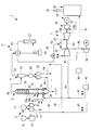
Hereinafter, the gasification furnace equipment according to the first embodiment of the present invention will be described with reference to the drawings. FIG. 1 shows a schematic configuration of an integrated coal gasification combined cycle facility (gasification combined cycle facility) to which the gasification combined cycle facility according to the first embodiment of the present invention is applied.
石炭ガス化複合発電設備(IGCC:Integrated Coal Gasification Combined Cycle)1は、ガス化炉設備3を備えている。ガス化炉設備3は、空気のみまたは空気及び酸素を酸化剤として用いており、石炭等の炭素含有固体燃料から可燃性ガスを生成する空気燃焼方式を採用している。石炭ガス化複合発電設備1は、ガス化炉設備3で生成したガス化ガスを、ガス精製設備5で精製して燃料ガスとした後、ガスタービン7に供給して発電を行っている。すなわち、石炭ガス化複合発電設備1は、空気燃焼方式(空気吹き)の発電設備となっている。なお、空気吹きに代えて酸素吹きの石炭ガス化複合発電設備としても良い。ガス化炉設備3に供給する炭素含有固体燃料としては、例えば石炭が用いられる。
The integrated coal gasification combined cycle (IGCC) 1 is equipped with a
石炭ガス化複合発電設備1は、ガス化炉設備3と、ガス精製設備5と、ガスタービン7と、蒸気タービン18と、発電機19と、排熱回収ボイラ(HRSG:Heat Recovery Steam Generator)20と、制御装置90とを備えている。
The integrated coal gasification combined cycle equipment 1 includes a gasification combined
ガス化炉設備3は、給炭設備9を備えている。給炭設備9は、原炭として炭素含有固体燃料である石炭が給炭バンカ12から供給され、石炭を石炭ミル13で粉砕することで、細かい粒子状に粉砕した微粉炭を製造する。石炭ミル13で製造された微粉炭は、微粉炭ビン17に一時貯留され、各微粉炭供給ホッパ14から給炭ライン15を経て、空気分離設備(ASU)42から供給される搬送用イナートガスとしての窒素ガスによって加圧されて、ガス化炉設備3へ向けて供給される。イナートガスとは、酸素含有率が約5体積%以下の不活性ガスであり、窒素ガスや二酸化炭素ガスやアルゴンガスなどが代表例であるが、必ずしも約5%以下に制限されるものではない。
The
ガス化炉設備3は、給炭設備9で製造された微粉炭が供給されると共に、チャー回収設備11で回収されたチャー(石炭の未反応分と灰分)が再利用を目的として供給されている。
ガス化炉設備3には、ガスタービン7の圧縮機61から圧縮空気供給ライン41が接続されており、圧縮機61で圧縮された圧縮空気の一部が昇圧機68で所定圧力に昇圧されてガス化炉16に供給可能となっている。
The
A compressed
空気分離設備42は、大気中の空気から窒素と酸素を分離生成するものであり、窒素供給ライン43によって空気分離設備42とガス化炉設備3とが接続されている。窒素供給ライン43には、給炭設備9からの給炭ライン15が接続されている。空気分離設備42は、酸素供給ライン47によって、圧縮空気供給ライン41と接続されている。
The
空気分離設備42によって分離された窒素は、窒素供給ライン43を流通することで、微粉炭の搬送用ガスとして利用される。また、空気分離設備42によって分離された酸素は、酸素供給ライン47及び圧縮空気供給ライン41を流通することで、ガス化炉設備3において酸化剤として利用される。
The nitrogen separated by the
ガス化炉設備3は、例えば、2段噴流床形式のガス化炉16を備えている。ガス化炉設備3は、内部に供給された石炭(微粉炭)およびチャーを酸化剤(空気、酸素)により部分燃焼させることでガス化させ生成ガスとする。ガス化炉16は、微粉炭をガス化するガス化炉本体16aと、ガス化炉本体16aを内部に収容して加圧状態を保持する圧力容器16bとを備えている。ガス化炉本体16a内は、例えば、3〜4MPa(ゲージ圧)とされている。
The
バーナ30,31は、上下二段に設けられている。下方のバーナ30に相当する位置には、コンバスタ部32が設けられており、微粉炭及び/又はチャーの一部を燃焼させることでガス化のための熱、CO2やH2Oを供給する。上方のバーナ31に相当する位置には、リダクタ部33が設けられ、微粉炭をガス化する。
The
リダクタ部33の下流側には、ガス冷却器としてのシンガスクーラ35が設けられており、生成ガスを所定温度まで冷却してからチャー回収設備(チャー分離器)11に供給する。シンガスクーラ35では蒸気が生成され、生成後の蒸気は排熱回収ボイラ20へと導かれる。
A
ガス化炉設備3には、チャー回収設備11に向けて生成ガスを供給する生成ガスライン49が接続されており、チャーを含む生成ガスが排出可能となっている。
A
チャー回収設備11は、集塵設備51と複数のチャー供給ホッパ52とを備えている。この場合、集塵設備51は、1つまたは複数のサイクロンやポーラスフィルタにより構成され、ガス化炉設備3で生成された生成ガスに含有するチャーを回収することができる。そして、チャーが分離された生成ガスは、ガス排出ライン53を通してガス精製設備5に送られる。
The char collection facility 11 includes a
チャー供給ホッパ52は、集塵設備51で生成ガスから回収されたチャーを貯留するものである。集塵設備51とチャー供給ホッパ52との間には、チャービン54が配置されている。チャービン54に対して、複数のチャー供給ホッパ52がそれぞれ接続されている。チャー供給ホッパ52からのチャー戻しライン46がチャー搬送系統45に接続されている。
The
ガス精製設備5は、チャー回収設備11によりチャーが分離された生成ガスに対して、硫黄化合物や窒素化合物などの不純物を取り除くことで、ガス精製を行うものである。
ガス精製設備5は、生成ガスを精製して燃料ガスを製造し、これをガスタービン7に供給する。チャーが分離された生成ガス中にはまだ硫黄分(H2Sなど)が含まれているため、ガス精製設備5では、アミン吸収液などによって硫黄分を除去回収して、有効利用する。
The
The
ガス精製設備5は、熱交換器21、スクラバ24、H2S吸収塔(腐食ガス除去手段)27を備えている。
集塵設備51から導かれたガス化ガスは、熱交換器21にて熱交換して減温される。
The gasified gas led from the
スクラバ24は、ガス化ガスに含まれる塩化水素(HCL)およびアンモニア(NH4)等の不純物を除去する装置である。スクラバ24としては、例えば、水等の吸収液を噴霧してガス化ガス中に接触させる湿式スクラバが用いられる。
The
スクラバ24を通過したガス化ガスは、H2S吸収塔27にてH2Sが除去される。H2S吸収塔27にてH2Sが除去されたガス化ガスは、精製ガス供給ライン28を通過する際に熱交換器21にて加温された後に、ガスタービン7の燃焼器62へと導かれる。
H 2 S is removed from the gasified gas that has passed through the
ガスタービン7は、圧縮機61、燃焼器62、タービン63を備えており、圧縮機61とタービン63とは、回転軸64により連結されている。燃焼器62には、圧縮機61からの圧縮空気供給ライン65が接続されると共に、ガス精製設備5の精製ガス供給ライン28が接続された燃料ガス供給ライン66が接続されている。燃焼器62には、タービン63に燃焼ガスを供給する燃焼ガス供給ライン67が接続されている。
The
ガスタービン7は、圧縮機61からガス化炉設備3に延びる圧縮空気供給ライン41が設けられており、中途部に昇圧機68が設けられている。従って、燃焼器62では、圧縮機61から供給された圧縮空気の一部とガス精製設備5から供給された燃料ガスの少なくとも一部とを混合して燃焼させることで燃焼ガスを発生させ、発生させた燃焼ガスをタービン63へ向けて供給する。そして、タービン63は、供給された燃焼ガスにより回転軸64を回転駆動させることで発電機19を回転駆動させる。
The
蒸気タービン18は、ガスタービン7の回転軸64に連結されるタービン69を備えており、発電機19は、この回転軸64の基端部に連結されている。ガスタービン7のタービン63の排出側には、排ガスライン70が接続されている。排熱回収ボイラ20は、給水とタービン63の排ガスとの間で熱交換を行うことで、蒸気を生成するものである。そして、排熱回収ボイラ20は、蒸気タービン18との間に蒸気供給ライン71が設けられている。従って、蒸気タービン18では、排熱回収ボイラ20から供給された蒸気によりタービン69が回転駆動され、回転軸64を回転させることで発電機19を回転駆動させる。
The
排熱回収ボイラ20の出口には、煙突75が接続されており、燃焼ガスが大気へと放出される。なお、排熱回収ボイラ20の出口に、ガス浄化設備を設けても良い。
A
制御装置90は、石炭ガス化複合発電設備1の各部を制御する装置である。制御装置90は、例えば、CPU(Central Processing Unit)、RAM(Random Access Memory)、ROM(Read Only Memory)、及びコンピュータ読み取り可能な記憶媒体等から構成されている。そして、各種機能を実現するための一連の処理は、一例として、プログラムの形式で記憶媒体等に記憶されており、このプログラムをCPUがRAM等に読み出して、情報の加工・演算処理を実行することにより、各種機能が実現される。
The
次に、本実施形態のガス化炉設備3の給水系統について説明する。図2は、図1に示すガス化炉設備3の概略構成図である。
図2に示すように、ガス化炉設備3は、シンガスクーラ35と、蒸気ドラム39と、第1流路L1と、第2流路L2と、バイパス流路LBと、温度センサ(ガス温度検出部)91と、温度センサ(給水温度検出部)92と、給水流量調整弁93と、バイパス流量調整弁94と、逆止弁95と、を備える。
Next, the water supply system of the
As shown in FIG. 2, the
シンガスクーラ35は、ガス化炉本体16aに収容され、ガス化炉本体16aで生成されたガス化ガスとボイラ給水BFWとの熱交換をする装置である。シンガスクーラ35は、節炭器36を有する。
節炭器36は、第1流路L1から供給されるボイラ給水BFWをガス化ガスとの熱交換により加熱し、第2流路L2を介して気水分離器である蒸気ドラム39に供給する。
The
The
蒸気ドラム39で分離された蒸気は、排熱回収ボイラ20へ供給される。
The steam separated by the
第1流路L1は、シンガスクーラ35へボイラ給水BFWを供給する流路であり、第1流路L1を流通する給水の流量を調整する給水流量調整弁93が設けられている。
第2流路L2は、シンガスクーラ35でガス化ガスと熱交換したボイラ給水BFWを流通させる流路であり、シンガスクーラ35を通過したボイラ給水BFWの温度を検出する温度センサ92が設けられている。
The first flow path L1 is a flow path for supplying the boiler supply water BFW to the
The second flow path L2 is a flow path for circulating the boiler supply water BFW that has exchanged heat with the gasified gas in the
バイパス流路LBは、第1流路L1から第2流路L2へガス化ガスと熱交換していないボイラ給水BFWを迂回させる流路である。バイパス流路LBには、バイパス流路LBを流通するボイラ給水BFWの流量を調整するバイパス流量調整弁94と、第2流路L2から第1流路L1へボイラ給水BFWが逆流することを防止する逆止弁95とが設けられている。
The bypass flow path LB is a flow path that bypasses the boiler supply water BFW that has not exchanged heat with the gasified gas from the first flow path L1 to the second flow path L2. The bypass flow rate LB has a bypass flow
温度センサ91は、シンガスクーラ35の節炭器36を通過したガス化ガスの温度を検出するセンサである。温度センサ91は、生成ガスライン49に設けられている。なお、温度センサ91は、ガス化炉本体16aの内部の、節炭器36よりもガス化ガスの流通方向の下流側に設けてもよい。
The
次に、本実施形態のガス化炉設備3の動作について説明する。
なお、本実施形態において、制御装置90は、石炭ガス化複合発電設備1の全体を制御するものであるが、ガス化炉設備3の動作を制御する制御部を有している。そして、本実施形態のガス化炉設備3は、制御装置90が備える制御部を構成の一部として組み込んだものであってもよい。
Next, the operation of the
In the present embodiment, the
本実施形態のガス化炉設備3において、制御装置90は、温度センサ91が検出するガス化ガスの温度が所定下限温度を下回るかどうかを判断し、所定下限温度を下回ると判断した場合にバイパス流量調整弁94の開度を増加させる第1制御指令値を生成する。
In the
ここで、所定下限温度は、例えば、塩化水素あるいはアンモニアを除去する前に、ガス化ガスが塩化アンモニウムの顕著に析出する約230℃を下回らないように維持するために十分な高さの温度に設定する。本実施形態では、スクラバ24でガス化ガスから塩化水素とアンモニアが除去されるため、スクラバ24へ流入するガス化ガスの温度が230℃を上回るように所定下限温度を設定する。すなわち、所定下限温度は、230℃に、熱交換器21を通過する際に想定される温度降下分を加算した値以上に設定する。
Here, the predetermined lower limit temperature is set to a temperature sufficiently high to maintain the gasification gas so as not to fall below about 230 ° C., in which the gasification gas is significantly precipitated, for example, before removing hydrogen chloride or ammonia. Set. In the present embodiment, since hydrogen chloride and ammonia are removed from the gasification gas by the
次に、制御装置90は、温度センサ92が検出するボイラ給水BFWの温度が所定上限温度を上回るかどうかを判断し、所定上限温度を上回ると判断した場合にバイパス流量調整弁94の開度上限を決める。
Next, the
制御装置90は、第1制御指令値をバイパス流量調整弁94へ送信する。
バイパス流量調整弁94は、制御装置90から受信した第1制御指令値に応じて、開度を調整する。なお、制御装置90は、第1制御指令値により増加するバイパス流量調整弁94の開度が開度上限以下となるように第1制御指令値を補正する。
The
The bypass flow
以上のように、制御装置90は、温度センサ91が検出するガス化ガスの温度が所定下限温度を下回ると判断した場合に、ガス化ガスの温度が所定下限温度を下回らないようにバイパス流量調整弁94の開度を増加させる。バイパス流量調整弁94の開度を増加させることにより、節炭器36と熱交換せずにバイパス流路LBへ迂回するボイラ給水BFWの流量が増加し、それに伴って節炭器36を流通するボイラ給水BFWの流量が減少する。これにより、節炭器36出口のボイラ給水BFWの温度が上昇するため、ガス化ガスとボイラ給水BFWとの温度差が小さくなり、交換する熱量が低下する。
As described above, when the
また、制御装置90は、温度センサ92が検出するボイラ給水BFWの温度が所定上限温度を上回ると判断した場合に、ボイラ給水BFWの温度が所定上限温度を上回らないようにバイパス流量調整弁94の開度上限を決める。バイパス流量調整弁94の開度上限を決めることにより、節炭器36に供給されるボイラ給水BFWの流量の下限が決まり、それに伴って節炭器36でガス化ガスとの熱交換により加熱されるボイラ給水BFWの温度の上限が決まる。
Further, when the
以上説明した本実施形態の石炭ガス化複合発電設備1が奏する作用および効果について説明する。
本実施形態の石炭ガス化複合発電設備1が備えるガス化炉設備3によれば、温度センサ91が検出するガス化ガスの温度が所定下限温度を下回らないように、節炭器36でガス化ガスとボイラ給水BFWとが交換する熱量が制御される。そのため、例えば、節炭器36の伝熱面(図示略)の清掃等により節炭器36の伝熱性能が急激に向上する場合であっても、ガス化ガスの温度が過度に低下せずに所定下限温度を下回らないように維持される。よって、ガス化炉本体16aで生成されたガス化ガスの温度が過度に低下して配管等の閉塞や腐食を引き起こす不具合を抑制することができる。
The operation and effect of the integrated coal gasification combined cycle facility 1 of the present embodiment described above will be described.
According to the
本実施形態のガス化炉設備3は、ボイラ給水BFWを節炭器36へ供給する第1流路L1と、節炭器36でガス化ガスと熱交換したボイラ給水BFWを流通させる第2流路L2と、第1流路L1から第2流路L2へガス化ガスと熱交換していないボイラ給水BFWを迂回させるバイパス流路LBと、バイパス流路LBに配置され、バイパス流路LBを流通するボイラ給水BFWの流量を調整するバイパス流量調整弁94と、を備える。そして、制御装置90は、温度センサ91が検出するガス化ガスの温度が所定下限温度を下回らないようにバイパス流量調整弁94を制御する。
In the
本実施形態のガス化炉設備3によれば、バイパス流量調整弁94によって第1流路L1から節炭器36へ供給されるボイラ給水の流量が制御され、それに伴って節炭器36でガス化ガスとボイラ給水BFWとが交換する熱量が制御される。よって、温度センサ91が検出するガス化ガスの温度が所定下限温度を下回らないようにすることができる。
According to the
また、本実施形態のガス化炉設備3によれば、温度センサ92が検出するボイラ給水BFWの温度が蒸発温度以下の所定上限温度を上回らないように、バイパス流量調整弁94の開度上限が決められる。バイパス流路LBに設けられたバイパス流量調整弁94の開度上限を決めることにより、節炭器36へ供給されるボイラ給水BFWの流量の下限が決まり、それに伴って節炭器36でガス化ガスとボイラ給水BFWとが交換する熱量が制御される。よって、第2流路L2を流通するボイラ給水BFWが流路内で蒸発して熱効率が低下する不具合を抑制することができる。
Further, according to the
〔第2実施形態〕
次に、本発明の第2実施形態の石炭ガス化複合発電設備について説明する。本実施形態の石炭ガス化複合発電設備は、第1実施形態の石炭ガス化複合発電設備1の変形例であり、以下で特に説明する場合を除き、第1実施形態の石炭ガス化複合発電設備1と同様であるものとする。
[Second Embodiment]
Next, the integrated coal gasification combined cycle equipment of the second embodiment of the present invention will be described. The integrated coal gasification combined cycle facility of the present embodiment is a modification of the integrated coal gasification combined cycle facility 1 of the first embodiment, and the coal gasification combined cycle facility of the first embodiment is not specified below. It is assumed that it is the same as 1.
第1実施形態の石炭ガス化複合発電設備1のガス化炉設備3は、第1流路L1から第2流路L2へボイラ給水BFWを迂回させるバイパス流路LBと、バイパス流路LBに設けられるバイパス流量調整弁94を備えるものであった。
それに対して、本実施形態のガス化炉設備3Aは、第2流路L2から第1流路L1へボイラ給水BFWを循環させる循環流路LCと、循環流路LCに設けられる循環流量調整弁96を備えるものである。
The
On the other hand, in the
図3に示すように、本実施形態のガス化炉設備3Aは、シンガスクーラ35と、蒸気ドラム39と、第1流路L1と、第2流路L2と、循環流路LCと、温度センサ91と、温度センサ92と、給水流量調整弁93と、循環流量調整弁96と、循環ポンプ97と、を備える。
As shown in FIG. 3, the
循環流路LCは、第2流路L2から第1流路L1へガス化ガスと熱交換したボイラ給水BFWを循環させる流路である。循環流路LCには、循環流路LCを流通するボイラ給水BFWの流量を調整する循環流量調整弁96と、第2流路L2から第1流路L1へボイラ給水BFWを循環させる循環ポンプ97とが設けられている。
The circulation flow path LC is a flow path for circulating the boiler supply water BFW that has exchanged heat with the gasification gas from the second flow path L2 to the first flow path L1. The circulation flow path LC includes a circulation flow
次に、本実施形態のガス化炉設備3Aの動作について説明する。
本実施形態のガス化炉設備3Aにおいて、制御装置90は、温度センサ91が検出するガス化ガスの温度が所定下限温度を下回るかどうかを判断し、所定下限温度を下回ると判断した場合に循環流量調整弁96の開度を増加させる第1制御指令値を生成する。
ここで、所定下限温度は、第1実施形態と同様に、塩化アンモニウムが顕著に析出する230℃に、熱交換器21を通過する際に想定される温度降下分を加算した値以上に設定する。
Next, the operation of the
In the
Here, the predetermined lower limit temperature is set to a value equal to or higher than the value obtained by adding the temperature drop expected when passing through the
次に、制御装置90は、温度センサ92が検出するボイラ給水BFWの温度が所定上限温度を上回るかどうかを判断し、所定上限温度を上回ると判断した場合に循環流量調整弁96の開度上限を決める。
Next, the
制御装置90は、第1制御指令値を循環流量調整弁96へ送信する。
循環流量調整弁96は、制御装置90から受信した第1制御指令値に応じて、開度を調整する。なお、制御装置90は、第1制御指令値により増加する循環流量調整弁96の開度が開度上限以下となるように第1制御指令値を補正する。
The
The circulation flow
以上のように、制御装置90は、温度センサ91が検出するガス化ガスの温度が所定下限温度を下回ると判断した場合に、ガス化ガスの温度が所定下限温度を下回らないように循環流量調整弁96の開度を増加させる。循環流量調整弁96の開度を増加させることにより、節炭器36と熱交換して循環流路LCへ循環するボイラ給水BFWの流量が増加し、それに伴って節炭器36へ供給されるボイラ給水BFWの温度が増加してガス化ガスとボイラ給水BFWとが交換する熱量が低下する。
As described above, when the
また、制御装置90は、温度センサ92が検出するボイラ給水BFWの温度が所定上限温度を上回ると判断した場合に、ボイラ給水BFWの温度が所定上限温度を上回らないように循環流量調整弁96の開度上限を決める。循環流量調整弁96の開度上限を決めることにより、節炭器36に供給されるボイラ給水BFWの流量の下限が決まり、それに伴って節炭器36でガス化ガスとの熱交換により加熱されるボイラ給水BFWの流量の温度の上限が決まる。
Further, when the
以上説明した本実施形態の石炭ガス化複合発電設備1が奏する作用および効果について説明する。
本実施形態のガス化炉設備3Aは、ボイラ給水BFWを節炭器36へ供給する第1流路L1と、節炭器36でガス化ガスと熱交換したボイラ給水BFWを流通させる第2流路L2と、第2流路L2から第1流路L1へガス化ガスと熱交換したボイラ給水BFWを循環させる循環流路LCと、循環流路LCに配置され、循環流路LCを流通するボイラ給水BFWの流量を調整する循環流量調整弁96と、を備える。そして、制御装置90は、温度センサ91が検出するガス化ガスの温度が所定下限温度を下回らないように循環流量調整弁96を制御する。
The operation and effect of the integrated coal gasification combined cycle facility 1 of the present embodiment described above will be described.
In the
本実施形態のガス化炉設備3Aによれば、循環流量調整弁96によって第2流路L2から第1流路L1へ循環させるボイラ給水BFWの流量が制御され、それに伴って第1流路L1から節炭器36へ供給されるボイラ給水BFWの温度と節炭器36でガス化ガスとボイラ給水BFWとが交換する熱量が制御される。よって、温度センサ91が検出するガス化ガスの温度が所定下限温度を下回らないようにすることができる。
According to the
また、本実施形態のガス化炉設備3Aによれば、制御装置90が、温度センサ91が検出するガス化ガスの温度が所定下限温度を下回る場合であっても、温度センサ92が検出するボイラ給水BFWの温度が所定上限温度を上回らないように循環流量調整弁96の上限を決める。
このようにすることで、第2流路L2を流通するボイラ給水BFWが流路内で蒸発して蒸気ドラムでの汽水分離性能が低下する不具合を優先的に抑制しつつ、ガス化炉本体16aで生成されたガス化ガスの温度が過度に低下する不具合を抑制することができる。
Further, according to the
By doing so, the gasifier
〔第3実施形態〕
次に、本発明の第3実施形態の石炭ガス化複合発電設備について説明する。本実施形態の石炭ガス化複合発電設備は、第1実施形態の石炭ガス化複合発電設備1の変形例であり、以下で特に説明する場合を除き、第1実施形態の石炭ガス化複合発電設備1と同様であるものとする。
[Third Embodiment]
Next, the integrated coal gasification combined cycle facility according to the third embodiment of the present invention will be described. The integrated coal gasification combined cycle facility of the present embodiment is a modification of the integrated coal gasification combined cycle facility 1 of the first embodiment, and the coal gasification combined cycle facility of the first embodiment is not specified below. It is assumed that it is the same as 1.
第1実施形態の石炭ガス化複合発電設備1のガス化炉設備3は、第1流路L1から第2流路L2へボイラ給水BFWを迂回させるバイパス流路LBと、バイパス流路LBに設けられるバイパス流量調整弁94を備えるものであった。
それに対して、本実施形態のガス化炉設備3Bは、節炭器36Aが第1熱交換部36Aaと第2熱交換部36Abとを有し、第1流路L1から第3流路L3へガス化ガスと熱交換していないボイラ給水BFWを迂回させるバイパス流路LBaと、バイパス流路LBaに配置されるバイパス流量調整弁99と、を備えるものである。
The
On the other hand, in the
図4に示すように、本実施形態のガス化炉設備3Bは、シンガスクーラ35Aと、蒸気ドラム39と、第1流路L1と、第2流路L2と、第3流路L3と、バイパス流路LBaと、温度センサ91と、温度センサ92と、給水流量調整弁93と、供給流量調整弁98と、バイパス流量調整弁99と、逆止弁100と、を備える。
本実施形態のシンガスクーラ35Aが備える節炭器36Aは、ガス化ガスの流通方向の下流側から順に、第1熱交換部36Aaと、第2熱交換部36Abと、を有する。
As shown in FIG. 4, the
The
第1流路L1は、節炭器36Aの第1熱交換部36Aaへボイラ給水BFWを供給する流路であり、第1流路L1を流通する給水の流量を調整する供給流量調整弁98が設けられている。
第2流路L2は、節炭器36Aの第2熱交換部36Abでガス化ガスと熱交換したボイラ給水BFWを流通させる流路であり、節炭器36Aを通過したボイラ給水BFWの温度を検出する温度センサ92が設けられている。
第3流路L3は、第1熱交換部36Aaを通過したボイラ給水BFWを第2熱交換部36Abへ供給する流路である。なお、第3流路L3から第1熱交換部36Aaへボイラ給水BFWが逆流しないように逆止弁100が設けられている。
The first flow path L1 is a flow path for supplying the boiler supply water BFW to the first heat exchange portion 36Aa of the
The second flow path L2 is a flow path for circulating the boiler water supply BFW that has exchanged heat with the gasified gas in the second heat exchange section 36Ab of the
The third flow path L3 is a flow path for supplying the boiler water supply BFW that has passed through the first heat exchange section 36Aa to the second heat exchange section 36Ab. A
バイパス流路LBaは、第1流路L1から第3流路L3へガス化ガスと熱交換していないボイラ給水BFWを迂回させる流路である。バイパス流路LBaには、バイパス流路LBaを流通するボイラ給水BFWの流量を調整するバイパス流量調整弁99が設けられている。
The bypass flow path LBa is a flow path that bypasses the boiler supply water BFW that has not exchanged heat with the gasified gas from the first flow path L1 to the third flow path L3. The bypass flow path LBa is provided with a bypass flow
次に、本実施形態のガス化炉設備3Bの動作について説明する。
本実施形態のガス化炉設備3において、制御装置90は、温度センサ91が検出するガス化ガスの温度が所定下限温度を下回るかどうかを判断し、所定下限温度を下回ると判断した場合にバイパス流量調整弁99の開度を増加させる第1制御指令値を生成する。
Next, the operation of the
In the
ここで、所定下限温度は、第1実施形態と同様に、塩化アンモニウムが顕著に析出する230℃に、熱交換器21を通過する際に想定される温度降下分を加算した値以上に設定する。
Here, the predetermined lower limit temperature is set to a value equal to or higher than the value obtained by adding the temperature drop expected when passing through the
次に、制御装置90は、温度センサ92が検出するボイラ給水BFWの温度が所定上限温度を上回るかどうかを判断し、所定上限温度を上回ると判断した場合にバイパス流量調整弁99の開度上限を決める。
Next, the
制御装置90は、第1制御指令値をバイパス流量調整弁99へ送信する。
バイパス流量調整弁99は、制御装置90から受信した第1制御指令値に応じて、開度を調整する。なお、制御装置90は、第1制御指令値により増加するバイパス流量調整弁99の開度が開度上限以下となるように第1制御指令値を補正する。
The
The bypass flow
以上のように、制御装置90は、温度センサ91が検出するガス化ガスの温度が所定下限温度を下回ると判断した場合に、ガス化ガスの温度が所定下限温度を下回らないようにバイパス流量調整弁99の開度を増加させる。バイパス流量調整弁99の開度を増加させることにより、第1熱交換部36Aaと熱交換せずにバイパス流路LBaへ迂回するボイラ給水BFWの流量が増加し、それに伴って節炭器36A(第1熱交換部36Aa)でガス化ガスとボイラ給水BFWとが交換する熱量が低下する。
なお、バイパス流量調整弁99の開度を増加させる場合には、供給流量調整弁98の開度を減少させるのが望ましい。ただし、供給流量調整弁98の開度をゼロとしてしまうと第1熱交換部36Aaが温度上昇してしまうとため、急激な温度上昇を抑制する程度の流量を確保するのが望ましい。
As described above, when the
When increasing the opening degree of the bypass flow
また、制御装置90は、温度センサ92が検出するボイラ給水BFWの温度が所定上限温度を上回ると判断した場合に、ボイラ給水BFWの温度が所定上限温度を上回らないようにバイパス流量調整弁99の開度上限を決める。バイパス流量調整弁99の開度上限を決めることにより、節炭器36Aに供給されるボイラ給水BFWの流量の下限が決まり、それに伴って節炭器36Aでガス化ガスとの熱交換により加熱されるボイラ給水BFWの温度の上限が決まる。
Further, when the
以上説明した本実施形態の石炭ガス化複合発電設備1が奏する作用および効果について説明する。
本実施形態のガス化炉設備3Bにおいて、節炭器36Aは、第1熱交換部36Aaと第2熱交換部36Abとを有し、ボイラ給水BFWを第1熱交換部36Aaへ供給する第1流路L1と、第2熱交換部36Abでガス化ガスと熱交換したボイラ給水BFWを流通させる第2流路L2と、第1熱交換部36Aaでガス化ガスと熱交換したボイラ給水BFWを第2熱交換部36Abへ導く第3流路L3と、第1流路L1から第3流路L3へガス化ガスと熱交換していないボイラ給水BFWを迂回させるバイパス流路LBaと、バイパス流路LBaに配置され、バイパス流路LBaを流通するボイラ給水の流量を調整するバイパス流量調整弁99と、を備える。そして、制御装置90は、温度センサ91が検出するガス化ガスの温度が所定下限温度を下回らないようにバイパス流量調整弁99を制御する。
The operation and effect of the integrated coal gasification combined cycle facility 1 of the present embodiment described above will be described.
In the
本実施形態のガス化炉設備3Bによれば、バイパス流量調整弁99によって第1流路L1から第1熱交換部36Aaへ供給されるボイラ給水BFWの流量が制御され、それに伴って第1熱交換部36Aaでガス化ガスとボイラ給水BFWとが交換する熱量が制御される。よって、温度センサ91が検出するガス化ガスの温度が所定下限温度を下回らないようにすることができる。
According to the
〔他の実施形態〕
なお、本実施形態では、石炭ガス化複合発電設備をガス化炉設備の適用例の一例として説明したが、石炭ガス化複合発電設備1以外のプラント、例えば所望の化学種を生成ガスから得るためのガス化炉設備として用いてもよい。この場合には、ガスタービン等の発電設備を省略する。
[Other Embodiments]
In the present embodiment, the integrated coal gasification combined cycle equipment has been described as an example of application of the integrated gasification combined cycle equipment, but in order to obtain a plant other than the integrated coal gasification combined cycle equipment 1, for example, a desired chemical species from the produced gas. It may be used as the gasification furnace equipment of. In this case, power generation equipment such as a gas turbine is omitted.
また、上述した実施形態では、燃料として石炭としたが、石炭に限らず、再生可能な生物由来の有機性資源として使用されるバイオマスであってもよく、例えば、間伐材、廃材木、流木、草類、廃棄物、汚泥、タイヤ及びこれらを原料としたリサイクル燃料(ペレットやチップ)などを使用することも可能である。 Further, in the above-described embodiment, coal is used as the fuel, but the fuel is not limited to coal, and may be biomass used as an organic resource derived from renewable organisms. For example, thinned wood, waste wood, drifting wood, etc. It is also possible to use grasses, wastes, sludges, tires and recycled fuels (pellets and chips) made from these.
また、本実施形態はガス化炉として、タワー型ガス化炉について説明してきたが、ガスの流通経路が上部で略逆U字状に折り返すクロスオーバー型ガス化炉としても良い。 Further, although the tower type gasification furnace has been described as the gasification furnace in this embodiment, it may be a crossover type gasification furnace in which the gas distribution path is folded back in a substantially inverted U shape at the upper part.
1 石炭ガス化複合発電設備(ガス化複合発電設備)
3,3A,3B ガス化炉設備
5 ガス精製設備
7 ガスタービン
16 ガス化炉
16a ガス化炉本体
16b 圧力容器
19 発電機
20 排熱回収ボイラ
21 熱交換器
24 スクラバ
27 H2S吸収塔(腐食ガス除去手段)
28 精製ガス供給ライン
35 シンガスクーラ
36 節炭器
39 蒸気ドラム
90 制御装置
91 温度センサ(ガス温度検出部)
92 温度センサ(給水温度検出部)
93 給水流量調整弁
94,99 バイパス流量調整弁
95 逆止弁
96 循環流量調整弁
97 循環ポンプ
L1 第1流路
L2 第2流路
LB バイパス流路
1 Integrated coal gasification combined cycle equipment (gasification combined cycle equipment)
3,3A, 3B
28 Refined
92 Temperature sensor (water supply temperature detector)
93 Water supply flow
Claims (7)
前記ガス化炉本体に収容され、該ガス化炉本体で生成されたガス化ガスと給水との熱交換をする熱交換器と、
前記熱交換器を通過した前記ガス化ガスの温度を検出するガス温度検出部と、
前記ガス温度検出部が検出する前記ガス化ガスの温度が所定下限温度を下回らないように、前記熱交換器で前記ガス化ガスと前記給水とが交換する熱量を制御する制御部と、
前記給水を前記熱交換器へ供給する第1流路と、
前記熱交換器で前記ガス化ガスと熱交換した前記給水を流通させる第2流路と、
前記第2流路から前記第1流路へ前記ガス化ガスと熱交換した前記給水を循環させる循環流路と、
前記循環流路に配置され、該循環流路を流通する前記給水の流量を調整する循環流量調整弁と、を備え、
前記制御部は、前記ガス温度検出部が検出する前記ガス化ガスの温度が前記所定下限温度を下回らないように前記循環流量調整弁を制御するガス化炉設備。 The gasifier body that gasifies carbon-containing solid fuel and
A heat exchanger housed in the gasification furnace main body and exchanging heat between the gasification gas generated in the gasification furnace main body and water supply.
A gas temperature detector that detects the temperature of the gasified gas that has passed through the heat exchanger, and
A control unit that controls the amount of heat exchanged between the gasified gas and the water supply by the heat exchanger so that the temperature of the gasified gas detected by the gas temperature detecting unit does not fall below a predetermined lower limit temperature.
A first flow path for supplying the water supply to the heat exchanger,
A second flow path for circulating the water supply that has exchanged heat with the gasification gas in the heat exchanger, and
A circulation flow path for circulating the water supply that has exchanged heat with the gasification gas from the second flow path to the first flow path,
A circulation flow rate adjusting valve which is arranged in the circulation flow path and adjusts the flow rate of the water supply flowing through the circulation flow path is provided.
Wherein the control unit, the gas temperature detecting unit is the gasification gas temperature is the predetermined lower limit temperature the circulation flow rate control valve control to Ruga gasification furnace facilities so as not to fall below the detecting.
前記ガス化炉本体に収容され、該ガス化炉本体で生成されたガス化ガスと給水との熱交換をする熱交換器と、
前記熱交換器を通過した前記ガス化ガスの温度を検出するガス温度検出部と、
前記ガス温度検出部が検出する前記ガス化ガスの温度が所定下限温度を下回らないように、前記熱交換器で前記ガス化ガスと前記給水とが交換する熱量を制御する制御部と、を備え、
前記熱交換器は、第1熱交換部と第2熱交換部とを有し、
前記給水を前記第1熱交換部へ供給する第1流路と、
前記第2熱交換部で前記ガス化ガスと熱交換した前記給水を流通させる第2流路と、
前記第1熱交換部で前記ガス化ガスと熱交換した前記給水を前記第2熱交換部へ導く第3流路と、
前記第1流路から前記第3流路へ前記ガス化ガスと熱交換していない前記給水を迂回させるバイパス流路と、
前記バイパス流路に配置され、該バイパス流路を流通する前記給水の流量を調整するバイパス流量調整弁と、を備え、
前記制御部は、前記ガス温度検出部が検出する前記ガス化ガスの温度が前記所定下限温度を下回らないように前記バイパス流量調整弁を制御するガス化炉設備。 The gasifier body that gasifies carbon-containing solid fuel and
A heat exchanger housed in the gasification furnace main body and exchanging heat between the gasification gas generated in the gasification furnace main body and water supply.
A gas temperature detector that detects the temperature of the gasified gas that has passed through the heat exchanger, and
A control unit for controlling the amount of heat exchanged between the gasified gas and the water supply by the heat exchanger is provided so that the temperature of the gasified gas detected by the gas temperature detecting unit does not fall below a predetermined lower limit temperature. ,
The heat exchanger has a first heat exchange section and a second heat exchange section.
A first flow path for supplying the water supply to the first heat exchange unit,
A second flow path for circulating the water supply that has exchanged heat with the gasification gas in the second heat exchange unit, and
A third flow path that guides the water supply that has exchanged heat with the gasification gas in the first heat exchange section to the second heat exchange section, and
A bypass flow path that bypasses the water supply that has not exchanged heat with the gasification gas from the first flow path to the third flow path,
A bypass flow rate adjusting valve which is arranged in the bypass flow path and adjusts the flow rate of the water supply flowing through the bypass flow path is provided.
Wherein the control unit, the gas temperature detecting unit is the gasification gas temperature is the predetermined lower limit temperature the bypass flow rate adjusting valve control to Ruga gasification furnace facilities so as not to fall below the detecting.
前記ガス化炉本体に収容され、該ガス化炉本体で生成されたガス化ガスと給水との熱交換をする熱交換器と、
前記熱交換器を通過した前記ガス化ガスの温度を検出するガス温度検出部と、
前記ガス温度検出部が検出する前記ガス化ガスの温度が所定下限温度を下回らないように、前記熱交換器で前記ガス化ガスと前記給水とが交換する熱量を制御する制御部と、
前記給水を前記熱交換器へ供給する第1流路と、
前記熱交換器で前記ガス化ガスと熱交換した前記給水を流通させる第2流路と、
前記第1流路から前記第2流路へ前記ガス化ガスと熱交換していない前記給水を迂回させるバイパス流路と、
前記バイパス流路に配置され、該バイパス流路を流通する前記給水の流量を調整するバイパス流量調整弁と、
前記熱交換器を通過した前記給水の温度を検出する給水温度検出部と、を備え、
前記制御部は、前記給水温度検出部が前記給水の蒸発温度以下の所定上限温度を上回らないように、前記バイパス流量調整弁の開度上限を決めるガス化炉設備。 The gasifier body that gasifies carbon-containing solid fuel and
A heat exchanger housed in the gasification furnace main body and exchanging heat between the gasification gas generated in the gasification furnace main body and water supply.
A gas temperature detector that detects the temperature of the gasified gas that has passed through the heat exchanger, and
A control unit that controls the amount of heat exchanged between the gasified gas and the water supply by the heat exchanger so that the temperature of the gasified gas detected by the gas temperature detecting unit does not fall below a predetermined lower limit temperature.
A first flow path for supplying the water supply to the heat exchanger,
A second flow path for circulating the water supply that has exchanged heat with the gasification gas in the heat exchanger, and
A bypass flow path that bypasses the water supply that has not exchanged heat with the gasification gas from the first flow path to the second flow path,
A bypass flow rate adjusting valve arranged in the bypass flow path and adjusting the flow rate of the water supply flowing through the bypass flow path, and a bypass flow rate adjusting valve.
A water supply temperature detection unit for detecting the temperature of the water supply that has passed through the heat exchanger is provided.
Wherein the control unit, the water supply so that the temperature detecting unit does not exceed a predetermined upper limit temperature below the water supply of the evaporation temperature, the bypass flow rate adjusting valve Ruga gasification furnaces determine the opening limit.
前記制御部は、前記給水温度検出部が前記給水の蒸発温度以下の所定上限温度を上回らないように、前記循環流量調整弁の開度上限を決める請求項1に記載のガス化炉設備。 A water supply temperature detection unit for detecting the temperature of the water supply that has passed through the heat exchanger is provided.
The gasification furnace equipment according to claim 1 , wherein the control unit determines an upper limit of the opening degree of the circulation flow rate adjusting valve so that the water supply temperature detection unit does not exceed a predetermined upper limit temperature equal to or lower than the evaporation temperature of the supply water.
前記ガス化炉設備から導かれたガス化ガスを用いて駆動されるガスタービンと、
該ガスタービンによって駆動される発電機と、
を備えていることを特徴とするガス化複合発電設備。 The gasifier equipment according to any one of claims 1 to 6 and
A gas turbine driven by using the gasified gas derived from the gasification furnace equipment, and
A generator driven by the gas turbine and
Gasification combined cycle equipment characterized by being equipped with.
Priority Applications (1)
| Application Number | Priority Date | Filing Date | Title |
|---|---|---|---|
| JP2017138245A JP6910872B2 (en) | 2017-07-14 | 2017-07-14 | Gasification furnace equipment and gasification combined cycle equipment equipped with this |
Applications Claiming Priority (1)
| Application Number | Priority Date | Filing Date | Title |
|---|---|---|---|
| JP2017138245A JP6910872B2 (en) | 2017-07-14 | 2017-07-14 | Gasification furnace equipment and gasification combined cycle equipment equipped with this |
Publications (2)
| Publication Number | Publication Date |
|---|---|
| JP2019019205A JP2019019205A (en) | 2019-02-07 |
| JP6910872B2 true JP6910872B2 (en) | 2021-07-28 |
Family
ID=65355048
Family Applications (1)
| Application Number | Title | Priority Date | Filing Date |
|---|---|---|---|
| JP2017138245A Active JP6910872B2 (en) | 2017-07-14 | 2017-07-14 | Gasification furnace equipment and gasification combined cycle equipment equipped with this |
Country Status (1)
| Country | Link |
|---|---|
| JP (1) | JP6910872B2 (en) |
Families Citing this family (2)
| Publication number | Priority date | Publication date | Assignee | Title |
|---|---|---|---|---|
| CN114570287B (en) * | 2022-05-07 | 2022-07-29 | 东营市赫邦化工有限公司 | Acid condensing and discharging device of two-in-one graphite synthesis furnace |
| CN115307147B (en) * | 2022-07-26 | 2025-01-21 | 光大环境科技(中国)有限公司 | A device and method for treating stale garbage coupled with domestic garbage |
Family Cites Families (4)
| Publication number | Priority date | Publication date | Assignee | Title |
|---|---|---|---|---|
| JPH05271670A (en) * | 1992-03-26 | 1993-10-19 | Ishikawajima Harima Heavy Ind Co Ltd | Temperature control device for crude gas at crude gas cooler exit |
| JP3017623B2 (en) * | 1993-09-28 | 2000-03-13 | 株式会社日立製作所 | Coal gasifier |
| JP5734234B2 (en) * | 2012-04-16 | 2015-06-17 | 三菱重工業株式会社 | Gasifier |
| JP6621310B2 (en) * | 2015-11-18 | 2019-12-18 | 三菱日立パワーシステムズ株式会社 | Gasification device, control device, combined gasification power generation facility and control method |
-
2017
- 2017-07-14 JP JP2017138245A patent/JP6910872B2/en active Active
Also Published As
| Publication number | Publication date |
|---|---|
| JP2019019205A (en) | 2019-02-07 |
Similar Documents
| Publication | Publication Date | Title |
|---|---|---|
| JP4981771B2 (en) | Coal gasification combined power generation facility | |
| JP5578907B2 (en) | Coal gasification combined power plant | |
| JP2020506983A (en) | Total steam gasification for supercritical CO2 power cycle system | |
| JP2010196606A (en) | Coal gasification combined power generation plant | |
| JP5518161B2 (en) | Gasifier | |
| JP6910872B2 (en) | Gasification furnace equipment and gasification combined cycle equipment equipped with this | |
| JP6742746B2 (en) | Pressurization system for powder supply hopper, gasification equipment, gasification combined cycle power generation equipment, and pressurization method for powder supply hopper | |
| JP2021143347A (en) | Gasification furnace facility and method of operating the same | |
| JP2001354975A (en) | Coal gasification and ash melting furnace and combined cycle system | |
| JP7039793B2 (en) | How to stop the slag discharge system, slag discharge system and gasification combined cycle | |
| JP5529678B2 (en) | Char recovery device | |
| JP6890982B2 (en) | How to start gasification furnace equipment, gasification combined cycle equipment and gasification furnace equipment | |
| JP7106367B2 (en) | Gasification equipment and its operation method | |
| JP6621310B2 (en) | Gasification device, control device, combined gasification power generation facility and control method | |
| JP7236194B2 (en) | Gas turbine facility, gasification facility, and method of operating gas turbine facility | |
| JP6590359B1 (en) | Hydrogen production method using biomass as raw material | |
| JP6957198B2 (en) | Gasification furnace equipment and gasification combined cycle equipment equipped with this | |
| JP7086675B2 (en) | Gasifier system | |
| JP7458795B2 (en) | Filter regeneration system, gasification combined cycle power generation equipment, and filter regeneration method | |
| JP4089079B2 (en) | Waste treatment method and waste treatment system | |
| JP2000328074A (en) | Coal gasification system | |
| JP7286504B2 (en) | Gasification facility and gasification combined cycle facility equipped with the same | |
| JP7334092B2 (en) | Integrated gasification combined cycle facility and its operation method | |
| JP4089080B2 (en) | Waste treatment method and waste treatment system | |
| JP2013173900A (en) | Gas purifying apparatus for gasification gas |
Legal Events
| Date | Code | Title | Description |
|---|---|---|---|
| A625 | Written request for application examination (by other person) |
Free format text: JAPANESE INTERMEDIATE CODE: A625 Effective date: 20200527 |
|
| A977 | Report on retrieval |
Free format text: JAPANESE INTERMEDIATE CODE: A971007 Effective date: 20210317 |
|
| A131 | Notification of reasons for refusal |
Free format text: JAPANESE INTERMEDIATE CODE: A131 Effective date: 20210323 |
|
| A521 | Written amendment |
Free format text: JAPANESE INTERMEDIATE CODE: A523 Effective date: 20210521 |
|
| TRDD | Decision of grant or rejection written | ||
| A01 | Written decision to grant a patent or to grant a registration (utility model) |
Free format text: JAPANESE INTERMEDIATE CODE: A01 Effective date: 20210608 |
|
| A61 | First payment of annual fees (during grant procedure) |
Free format text: JAPANESE INTERMEDIATE CODE: A61 Effective date: 20210707 |
|
| R150 | Certificate of patent or registration of utility model |
Ref document number: 6910872 Country of ref document: JP Free format text: JAPANESE INTERMEDIATE CODE: R150 |