JP6905642B2 - Integrated drain mast structure - Google Patents
Integrated drain mast structure Download PDFInfo
- Publication number
- JP6905642B2 JP6905642B2 JP2020547050A JP2020547050A JP6905642B2 JP 6905642 B2 JP6905642 B2 JP 6905642B2 JP 2020547050 A JP2020547050 A JP 2020547050A JP 2020547050 A JP2020547050 A JP 2020547050A JP 6905642 B2 JP6905642 B2 JP 6905642B2
- Authority
- JP
- Japan
- Prior art keywords
- fluid
- fairing
- tube section
- drain mast
- mast structure
- Prior art date
- Legal status (The legal status is an assumption and is not a legal conclusion. Google has not performed a legal analysis and makes no representation as to the accuracy of the status listed.)
- Active
Links
- 239000012530 fluid Substances 0.000 claims description 235
- 239000007788 liquid Substances 0.000 claims description 23
- 230000002093 peripheral effect Effects 0.000 claims description 18
- 230000008878 coupling Effects 0.000 claims description 4
- 238000010168 coupling process Methods 0.000 claims description 4
- 238000005859 coupling reaction Methods 0.000 claims description 4
- 238000005219 brazing Methods 0.000 claims description 3
- 238000003466 welding Methods 0.000 claims description 3
- 230000010354 integration Effects 0.000 claims 1
- 230000037361 pathway Effects 0.000 claims 1
- 238000012423 maintenance Methods 0.000 description 7
- 238000001514 detection method Methods 0.000 description 5
- 238000007689 inspection Methods 0.000 description 4
- 230000007704 transition Effects 0.000 description 4
- 238000011179 visual inspection Methods 0.000 description 4
- XEEYBQQBJWHFJM-UHFFFAOYSA-N Iron Chemical compound [Fe] XEEYBQQBJWHFJM-UHFFFAOYSA-N 0.000 description 2
- 239000012634 fragment Substances 0.000 description 2
- 238000009434 installation Methods 0.000 description 2
- 230000014759 maintenance of location Effects 0.000 description 2
- 229910052751 metal Inorganic materials 0.000 description 2
- 239000002184 metal Substances 0.000 description 2
- 230000008439 repair process Effects 0.000 description 2
- VYZAMTAEIAYCRO-UHFFFAOYSA-N Chromium Chemical compound [Cr] VYZAMTAEIAYCRO-UHFFFAOYSA-N 0.000 description 1
- 229910000990 Ni alloy Inorganic materials 0.000 description 1
- RTAQQCXQSZGOHL-UHFFFAOYSA-N Titanium Chemical compound [Ti] RTAQQCXQSZGOHL-UHFFFAOYSA-N 0.000 description 1
- 230000009471 action Effects 0.000 description 1
- 230000002411 adverse Effects 0.000 description 1
- 229910052782 aluminium Inorganic materials 0.000 description 1
- XAGFODPZIPBFFR-UHFFFAOYSA-N aluminium Chemical compound [Al] XAGFODPZIPBFFR-UHFFFAOYSA-N 0.000 description 1
- 230000000712 assembly Effects 0.000 description 1
- 238000000429 assembly Methods 0.000 description 1
- 230000009286 beneficial effect Effects 0.000 description 1
- 230000008901 benefit Effects 0.000 description 1
- 230000005540 biological transmission Effects 0.000 description 1
- 229910052804 chromium Inorganic materials 0.000 description 1
- 239000011651 chromium Substances 0.000 description 1
- 239000000446 fuel Substances 0.000 description 1
- 239000000295 fuel oil Substances 0.000 description 1
- 239000010720 hydraulic oil Substances 0.000 description 1
- 229910001026 inconel Inorganic materials 0.000 description 1
- 230000001939 inductive effect Effects 0.000 description 1
- 229910052742 iron Inorganic materials 0.000 description 1
- 239000010687 lubricating oil Substances 0.000 description 1
- 239000000463 material Substances 0.000 description 1
- 150000002739 metals Chemical class 0.000 description 1
- 238000000034 method Methods 0.000 description 1
- 230000004048 modification Effects 0.000 description 1
- 238000012986 modification Methods 0.000 description 1
- 239000003921 oil Substances 0.000 description 1
- -1 respectively Substances 0.000 description 1
- 238000010408 sweeping Methods 0.000 description 1
- 239000010936 titanium Substances 0.000 description 1
- 229910052719 titanium Inorganic materials 0.000 description 1
- 238000011144 upstream manufacturing Methods 0.000 description 1
- 239000011800 void material Substances 0.000 description 1
- XLYOFNOQVPJJNP-UHFFFAOYSA-N water Substances O XLYOFNOQVPJJNP-UHFFFAOYSA-N 0.000 description 1
- 239000013585 weight reducing agent Substances 0.000 description 1
Images


Classifications
-
- B—PERFORMING OPERATIONS; TRANSPORTING
- B64—AIRCRAFT; AVIATION; COSMONAUTICS
- B64C—AEROPLANES; HELICOPTERS
- B64C1/00—Fuselages; Constructional features common to fuselages, wings, stabilising surfaces or the like
- B64C1/14—Windows; Doors; Hatch covers or access panels; Surrounding frame structures; Canopies; Windscreens accessories therefor, e.g. pressure sensors, water deflectors, hinges, seals, handles, latches, windscreen wipers
- B64C1/1407—Doors; surrounding frames
- B64C1/1453—Drain masts
-
- B—PERFORMING OPERATIONS; TRANSPORTING
- B64—AIRCRAFT; AVIATION; COSMONAUTICS
- B64D—EQUIPMENT FOR FITTING IN OR TO AIRCRAFT; FLIGHT SUITS; PARACHUTES; ARRANGEMENT OR MOUNTING OF POWER PLANTS OR PROPULSION TRANSMISSIONS IN AIRCRAFT
- B64D1/00—Dropping, ejecting, releasing or receiving articles, liquids, or the like, in flight
- B64D1/16—Dropping or releasing powdered, liquid, or gaseous matter, e.g. for fire-fighting
-
- B—PERFORMING OPERATIONS; TRANSPORTING
- B64—AIRCRAFT; AVIATION; COSMONAUTICS
- B64D—EQUIPMENT FOR FITTING IN OR TO AIRCRAFT; FLIGHT SUITS; PARACHUTES; ARRANGEMENT OR MOUNTING OF POWER PLANTS OR PROPULSION TRANSMISSIONS IN AIRCRAFT
- B64D29/00—Power-plant nacelles, fairings or cowlings
-
- F—MECHANICAL ENGINEERING; LIGHTING; HEATING; WEAPONS; BLASTING
- F01—MACHINES OR ENGINES IN GENERAL; ENGINE PLANTS IN GENERAL; STEAM ENGINES
- F01D—NON-POSITIVE DISPLACEMENT MACHINES OR ENGINES, e.g. STEAM TURBINES
- F01D25/00—Component parts, details, or accessories, not provided for in, or of interest apart from, other groups
- F01D25/32—Collecting of condensation water; Drainage ; Removing solid particles
Landscapes
- Engineering & Computer Science (AREA)
- Aviation & Aerospace Engineering (AREA)
- Mechanical Engineering (AREA)
- General Engineering & Computer Science (AREA)
- Structures Of Non-Positive Displacement Pumps (AREA)
- Pipeline Systems (AREA)
- Rigid Pipes And Flexible Pipes (AREA)
- Exhaust Silencers (AREA)
Description
本発明は、航空機で使用されるガスタービンエンジンを含む、航空機における液体が排出されるコンポーネント(構成部品)に関する。ガスタービンエンジンの場合、様々なガスタービンエンジンのコンポーネントから生じる液体を排出するため、および、これらのコンポーネントからの液体の漏出の検出を容易にするために、一体化ドレインマスト構造が使用される。ドレインマスト構造は、航空機の胴体と関連して使用されることも可能であり、液体排出と共に、それらの液体の特性の検出および識別を容易にする。 The present invention relates to components that discharge liquids in an aircraft, including gas turbine engines used in the aircraft. For gas turbine engines, an integrated drain mast structure is used to drain liquids from various gas turbine engine components and to facilitate detection of liquid leaks from these components. The drain mast structure can also be used in connection with the fuselage of an aircraft, facilitating the detection and identification of the properties of those liquids as well as the discharge of the liquids.
最新の航空機に使用されるガスタービンエンジンは、安全な飛行に適切な操作および信頼性が不可欠な複雑な機器である。最新のガスタービンエンジンは、重要なコンポーネントを組み込んでおり、それらは大抵、液体を生成/運搬/消費、および/または含有する。例えば、燃料ポンプや油圧ポンプといったコンポーネントは、ジェット燃料や油圧油の流れをそれぞれ分配および制御し、オイルタンクなどのコンポーネントは液体を格納し、始動モータ、変速装置、アクチュエータ、圧縮機、発電機などのコンポーネントは、潤滑油の供給を必要とする。これらすべての液体は、各コンポーネントまたは貯蔵容器から漏出またはオーバーフローする可能性がある。 Gas turbine engines used in modern aircraft are complex equipment where proper operation and reliability are essential for safe flight. Modern gas turbine engines incorporate important components that usually produce / transport / consume and / or contain liquids. For example, components such as fuel pumps and hydraulic pumps distribute and control the flow of jet fuel and hydraulic oil, respectively, components such as oil tanks store liquids, starting motors, transmissions, actuators, compressors, generators, etc. Components require a supply of lubricating oil. All these liquids can leak or overflow from each component or storage container.
タービンエンジンからの液体漏出の検出は、もし何の対策も取られなければ、エンジンコンポーネントが故障している、または近い将来故障する可能性があることを示す場合がある。タービンエンジン内、およびその周囲に漏出する液体を収集して、他の問題を潜在的に隠したり、および/または他の故障を誘発したりする代わりに、液体を排出するための排出部を提供することは、好ましい設計検討である。 Detection of liquid leaks from turbine engines may indicate that engine components have failed or may fail in the near future if no action is taken. Collects liquid leaking into and around the turbine engine to provide a drain for draining the liquid instead of potentially hiding other problems and / or inducing other failures. What to do is a preferred design study.
したがって、通常、航空機のタービンエンジンは、エンジンコンポーネントから漏出またはオーバーフローし得る液体のための排出部を提供するとともに、潜在的なメンテナンスまたは他の重大なエンジン運転状態を示し得る漏出の早期検出を提供するために、特定のエンジンコンポーネントにそれぞれ連結される複数のドレインラインを含んでいる。典型的な先行技術の設計では、個々のドレインラインのそれぞれは、個々のエンジンコンポーネントから、タービンエンジンと並行して、中央の単一の場所へと経由し、エンジンカウルから延びるフェアリング構造に備わった複数の排出口を通って、漏出液体を排出させる。典型的には、各ドレインラインは、ドレインラインの望ましくない動作、摩耗、および/または破損を防ぐために、ブラケットまたは締め具を使用して、エンジンカウル内に位置する支持構造またはマストに固定される。次いで、各流体ドレインラインは、支持構造に結合されたドレインフェアリングアセンブリに、接続金具、また、取付板、ブラケットおよび締め具を使用して接続されている。フェアリングは、エンジンカウルから外側方向に突出し、エンジンカウルに固定されている。 Therefore, aircraft turbine engines typically provide an outlet for liquids that can leak or overflow from engine components, as well as early detection of leaks that can indicate potential maintenance or other critical engine operating conditions. It contains multiple drain lines, each connected to a particular engine component. In a typical prior art design, each of the individual drain lines is provided in a fairing structure that extends from the engine cowl from the individual engine components through a single central location in parallel with the turbine engine. The leaked liquid is discharged through multiple outlets. Typically, each drain line is secured to a support structure or mast located within the engine cowl using brackets or fasteners to prevent unwanted movement, wear, and / or breakage of the drain line. .. Each fluid drain line is then connected to a drain fairing assembly coupled to the support structure using fittings and mounting plates, brackets and fasteners. The fairing protrudes outward from the engine cowl and is fixed to the engine cowl.
一般に、地上要員およびパイロットは、通常の航空機の運用の一部として、飛行の安全性に悪影響を及ぼすであろう明らかな状況を特定するために、航空機の重要部分の目視検査を実施し、多くの場合、それらの実施が必須とされる。多くの重要な航空機コンポーネントのなかで、航空機エンジンのドレインラインのフェアリングアセンブリは、特別な注意が払われるべき対象である。ドレインラインのフェアリングの、飛行前の目視検査は、将来的な壊滅的結果をもたらすエンジン故障につながる、重要コンポーネントの故障または将来的な故障の兆しであり得る、エンジンからの液体漏出を明らかにする。 In general, ground personnel and pilots carry out visual inspections of important parts of the aircraft to identify obvious situations that may adversely affect flight safety as part of normal aircraft operations, often. In the case of, their implementation is mandatory. Of the many important aircraft components, the fairing assembly of the aircraft engine drain line is a subject of special attention. Pre-flight visual inspection of the drainline fairing reveals liquid leaks from the engine, which can be a sign of critical component failure or future failure leading to engine failure with catastrophic future consequences. do.
例として、飛行前検査により、フェアリングからの液体のドリップ、またはフェアリング上に堆積したドリップの存在が明らかとなり得る。フェアリングに複数のドレイン排出口が備わっていたとしても、場合によっては、どの排出口から1以上の液体漏出があったのかを確認することは難しい場合があり、不可能ではないにせよ、注意が必要なエンジンコンポーネントの特定を困難にする。 As an example, pre-flight inspection may reveal the presence of liquid drip from the fairing, or drip deposited on the fairing. Even if the fairing has multiple drain outlets, it can be difficult, if not impossible, to determine from which outlet one or more liquid leaks. Makes it difficult to identify the required engine components.
同様に、航空機には、エンジンとは別に、液体の検出および特定とともに液体排出を必要とする他のコンポーネントが存在する。当該コンポーネントは、航空機胴体の底部に沿って位置する改良された一体化ドレインマストアセンブリによって、同様に恩恵を受け得る航空機排水管および貯氷箱を含み得る。 Similarly, an aircraft has other components that require liquid discharge as well as liquid detection and identification, apart from the engine. The component may include aircraft drains and ice bins that may also benefit from an improved integrated drain mast assembly located along the bottom of the aircraft fuselage.
従来技術が、エンジンカウルまたは胴体のどちらからの液体漏出に対応するかにかかわらず、かかる従来技術のドレインアセンブリの不都合な点は、飛行中に該当する構造にかかる振動および外力に耐えるのに十分に安全かつ強固な、完全なドレインラインアセンブリを形成するために、共に組み立てられなければならない多数の個々のコンポーネントを調達、追跡、および在庫管理する必要性と、個々のコンポーネントの集合した(合計の)全重量と、個々のドレインラインを個別に組み立て、経路を決め、支持構造、ブラケット、板、およびフェアリンングに固定するのにかかる時間と、最後に、完成アセンブリを航空機に据え付けるのにかかる時間とを含む。 Regardless of whether the prior art addresses liquid leakage from the engine cowl or fuselage, the disadvantage of such prior art drain assemblies is sufficient to withstand the vibrations and external forces of the relevant structure during flight. The need to procure, track, and inventory a large number of individual components that must be assembled together to form a secure, robust, complete drainline assembly, and a collection of individual components (total). ) Total weight and the time it takes to assemble, route and secure the individual drain lines individually to the support structure, brackets, plates, and fairing, and finally the time it takes to install the finished assembly on the aircraft. And include.
少なくとも先述の内容を鑑みると、本明細書に開示する改良されたドレインマスト構造の明白な必要性が存在する。 There is a clear need for the improved drain mast structure disclosed herein, at least in view of the above.
本発明の一実施形態では、航空機の筐体からの排液のための一体化ドレインマスト構造は、気流内に位置することを目的とした実質的に空気力学的フェアリングと一緒に、航空機内に位置することを目的とした自立式チューブセクションを備える。チューブセクションおよびフェアリングは、単一の一体構造が好ましく、一実施形態では、チューブセクションおよびフェアリングは、単一の一体化した均一な構造を形成するために、付加的に金属で製造されている。 In one embodiment of the invention, the integrated drain mast structure for drainage from the aircraft housing is in the aircraft, with substantially aerodynamic fairings intended to be located in the airflow. It has a free-standing tube section intended to be located in. The tube section and fairing are preferably a single integral structure, and in one embodiment the tube section and fairing are additionally made of metal to form a single integrated uniform structure. There is.
チューブセクションは、チューブセクション上端部からチューブセクション下端部に向かって延在する、一般に整列した複数の流体経路を含み、各流体経路は、自立式チューブセクションを通じて実質的に同一の厚さを有する周囲面を有し、当該周囲面の少なくとも一部は、他の整列した流体経路の少なくとも1つの周囲面の一部を共有している。チューブセクション内の各流体経路の上端部は、1または複数の流体源と、それぞれ流体連結するよう構成されている。自立式チューブセクションの断面積は、かかる断面積を最小化するように、一般に整列した複数の流体経路の合計幅(集合した幅)と実質的に対応していることが好ましい。チューブセクション内の複数の流体経路は、航空機が飛行中に、チューブセクションに付加されうる振動および他の外力に対する、チューブセクションの構造抵抗を増加するように、互いに傾斜し得ることが好ましい。本発明の1つの実施形態では、チューブセクションの振動および他の外力に対する構造抵抗をさらに強化する、凹部すなわち「砂時計(アワーグラス)」形状を創出するために、隣接する、チューブセクションの上端部に向かう流体経路とチューブセクションの下端部に向かう流体経路を分離している周壁が、上記部分の間の領域における、隣接する流体経路を分離する各周壁よりも厚くなっている。 The tube section contains a plurality of generally aligned fluid paths extending from the top of the tube section to the bottom of the tube section, each fluid path surrounding having substantially the same thickness through the free-standing tube section. It has a surface, and at least a part of the peripheral surface shares a part of at least one peripheral surface of another aligned fluid path. The upper end of each fluid path in the tube section is configured to be fluid-connected to one or more fluid sources, respectively. It is preferable that the cross-sectional area of the free-standing tube section substantially corresponds to the total width (aggregated width) of a plurality of generally aligned fluid paths so as to minimize such cross-sectional area. It is preferred that the multiple fluid paths within the tube section can be tilted with each other during flight so as to increase the structural resistance of the tube section to vibrations and other external forces that may be applied to the tube section. In one embodiment of the invention, at the top of the adjacent tube section to create a recess or "hourglass" shape that further enhances the structural resistance of the tube section to vibrations and other external forces. The perimeter wall separating the facilitating fluid path and the fluid path towards the lower end of the tube section is thicker than each perimeter wall separating adjacent fluid paths in the region between the portions.
フェアリングは、複数のフェアリング流体経路を含み、各フェアリング流体経路は、その上端部で、チューブセクションの下端部の各流体経路に接続される。本発明のこの実施形態において、各フェアリング流体経路は、その下端部で、フェアリングセクションに位置する複数の流体排出口の1つに接続される。本発明の一体化ドレインマストの1つの実施形態では、航空機の筐体は、航空機エンジンを包囲する航空機エンジンカウルを備え、自立式チューブセクションは、エンジンカウルによって包囲される領域内に位置している。フェアリングは、エンジンカウルの下方の外側面と実質的に同一平面上に配置されうるフランジを含んでおり、当該フランジはエンジンカウルから外側方向に、気流に向かって延在する。本発明の別の実施形態では、航空機の筐体は、航空機胴体そのものであり、この場合、一体化ドレインマストは、客室内部および外部の流体の排出を可能にし、胴体の下方外側表面上に取り付けられている。 The fairing comprises a plurality of fairing fluid paths, each fairing fluid path being connected to each fluid path at the lower end of the tube section at its upper end. In this embodiment of the invention, each fairing fluid path is connected at its lower end to one of a plurality of fluid outlets located in the fairing section. In one embodiment of the integrated drain mast of the present invention, the aircraft housing comprises an aircraft engine cowl that surrounds the aircraft engine, and the self-supporting tube section is located within the area surrounded by the engine cowl. .. The fairing includes a flange that can be located substantially coplanar with the lower outer surface of the engine cowl, which extends outward from the engine cowl towards the airflow. In another embodiment of the invention, the aircraft enclosure is the aircraft fuselage itself, in which case the integrated drain mast allows drainage of fluid inside and outside the cabin and is mounted on the lower outer surface of the fuselage. Has been done.
好適な実施形態のいずれにおいても、航空機流体が初期段階で収集される、または発生する複数の上流液体導管が、チューブセクション内の各流体経路の上端部のうちの1つとそれぞれ接続される。チューブセクションの経路の上端部と、各流体導管の1つとの接続を可能にするために、チューブセクションの上端部は分岐構造を含んでおり、複数のチューブセクション経路が互いに分離して、関連する流体導管のそれぞれとの接続を容易にし、この場合、流体導管は、分岐構造によって入れ子状に伸縮自在に(テレスコピックに)受けられ、例えば、ろう付け、溶接、またはねじ接続などの機械的結合によって、各経路に接続される。チューブセクション内の流体経路は、例えば、特定の、関連する航空機エンジンコンポーネントに必要とされる、各流体源によって生成される可能性の高い流体量を収容するのに適したサイズであってもよい。 In any of the preferred embodiments, a plurality of upstream liquid conduits from which aircraft fluid is initially collected or generated are connected to one of the upper ends of each fluid path within the tube section, respectively. To allow the connection between the top of the tube section path and one of each fluid conduit, the top of the tube section contains a bifurcated structure, with multiple tube section paths separated from each other and associated with each other. It facilitates connection with each of the fluid conduits, in which case the fluid conduits are received in a nested manner (telescopically) by a bifurcated structure, for example by mechanical coupling such as brazing, welding, or threaded connections. , Connected to each route. The fluid path within the tube section may be of a size suitable for accommodating, for example, the amount of fluid likely to be produced by each fluid source required for a particular, associated aircraft engine component. ..
フェアリングは、空気力学的な前方面(leading surface)、後方面(trailing surface)、および、反対側を向く側面を含む。フェアリングの1つの実施形態では、フェアリングの流体排出口は、フェアリングの両方の側面に位置している。1つの実施形態のフェアリングは、少なくとも1つの流体排出口のうちの1つと関連づけられた、少なくとも1つの流体用リッジ(fluid ridge)を含み、当該流体用リッジ(隆起)は、流体排出口の下縁(下方エッジ)に隣接して位置し、後方に向かって実質的に水平方向に、または、空気力学的に下方向に角度をつけて、フェアリング側部に沿って延在し、および、少なくとも1つの流体排出口の前縁の少なくとも一部に沿ってさらに延在する。その代わりに、液体排出部そのものが、ティアドロップ様または他の空気力学的形状をしていてもよい。本発明の一体化ドレインマスト構造のさらに別の実施形態では、フェアリングは、少なくとも1つの液体排出口と関連づいた少なくとも1つの溝を含み、当該溝は、各流体排出口の後縁から、後方に、フェアリングの側部に沿って、フェアリングの後方面に向かって延在する。 Fairings include aerodynamic leading surfaces, trailing surfaces, and opposite sides. In one embodiment of the fairing, the fluid outlets of the fairing are located on both sides of the fairing. The fairing of one embodiment comprises at least one fluid ridge associated with at least one of the fluid outlets, the fluid ridge of which is of the fluid outlet. Located adjacent to the lower edge (lower edge) and extending posteriorly substantially horizontally or aerodynamically downward along the fairing side and , Further extending along at least a portion of the anterior edge of at least one fluid outlet. Instead, the liquid outlet itself may have a teardrop-like or other aerodynamic shape. In yet another embodiment of the integrated drain mast structure of the present invention, the fairing comprises at least one groove associated with at least one liquid outlet, which groove is from the trailing edge of each fluid outlet. It extends posteriorly, along the sides of the fairing, towards the posterior surface of the fairing.
一体化ドレインマスト構造の別の実施形態では、複数の流体排出口が、フェアリングの片側にのみ配置され、フェアリングセクションの下方前縁からフェアリングの上方後縁に向かって、対角線上に方向づけられている。エンジンコンポーネントと関連付けられ、エンジンコンポーネントを特定する印が、1または複数の流体排出口に隣接して、任意で付されてもよい。 In another embodiment of the integrated drain mast structure, multiple fluid outlets are located on only one side of the fairing and are oriented diagonally from the lower front edge of the fairing section to the upper trailing edge of the fairing. Has been done. A mark associated with the engine component and identifying the engine component may optionally be placed adjacent to one or more fluid outlets.
先述の概要は例示的なものに過ぎず、限定を意図するものではない。上記の例示的態様、実施形態、および特徴であることに加え、詳細な説明、および付随する図面および請求項を参照することで、さらなる態様、実施形態および特徴が明白となろう。 The above outline is merely exemplary and is not intended to be limiting. In addition to the exemplary embodiments, embodiments, and features described above, further embodiments, embodiments, and features will become apparent by reference to the detailed description and accompanying drawings and claims.
本発明の理解をさらに促し、詳細な説明の一部を構成するために、付随する図面が提供される。これらの図面は本発明を説明するための実施形態と共に使用されるが、本発明に対する限定を構成するものではない。 Ancillary drawings are provided to further facilitate the understanding of the present invention and form part of a detailed description. These drawings are used with embodiments to illustrate the invention, but do not constitute a limitation to the invention.
図1は、本発明の1つの実施形態に従った、一体化ドレインマスト構造の斜視図であり、一体化ドレインマスト構造と、内部流体経路が備わったチューブセクションと、右側部に流体排出口とが備わったフェアリングとを図示している。 FIG. 1 is a perspective view of an integrated drain mast structure according to one embodiment of the present invention, with an integrated drain mast structure, a tube section provided with an internal fluid path, and a fluid outlet on the right side. Illustrated with a fairing equipped with.
図2は、本発明の一実施形態に従った、一体化ドレインマスト構造の斜視図であり、一体化ドレインマスト構造と、内部流体経路が備わったチューブセクションと、左側部に流体排出口が備わったフェアリングとを図示している。 FIG. 2 is a perspective view of an integrated drain mast structure according to an embodiment of the present invention, which includes an integrated drain mast structure, a tube section provided with an internal fluid path, and a fluid outlet on the left side. The fairing is illustrated.
図3は、本発明の一実施形態に従った、フェアリングの後縁の拡大後方立面図である。 FIG. 3 is an enlarged rear elevation view of the trailing edge of the fairing according to one embodiment of the present invention.
図4は、本発明の一実施形態に従った、フェアリングの前縁の拡大前方立面図である。 FIG. 4 is an enlarged front elevation view of the front edge of the fairing according to an embodiment of the present invention.
図5は、本発明の一実施形態に従った、図4の5−5線に沿った、矢印方向に見たチューブセクション内部を図示した断面図である。 FIG. 5 is a cross-sectional view illustrating the inside of the tube section as viewed in the direction of the arrow along line 5-5 of FIG. 4, according to an embodiment of the present invention.
図6は、本発明の一実施形態に従った、図4のフェアリングの左側立面図である。 FIG. 6 is a left elevation view of the fairing of FIG. 4 according to an embodiment of the present invention.
図7は、本発明の一実施形態に従った、図6の7−7線に沿った、矢印方向に見たチューブセクションの断片の断面図である。 FIG. 7 is a cross-sectional view of a fragment of a tube section viewed in the direction of the arrow along line 7-7 of FIG. 6, according to an embodiment of the present invention.
図8は、本発明の一実施形態に従った、フェアリングの左側立面図である。 FIG. 8 is a left elevation view of the fairing according to an embodiment of the present invention.
図9は、図8の実施形態の、図8の9−9線に沿った、矢印方向に見た、図8の実施形態の断片の断面図である。 FIG. 9 is a cross-sectional view of a fragment of the embodiment of FIG. 8 as viewed in the direction of the arrow along line 9-9 of FIG.
図10は、図1の一体化ドレインマストの上面図である。 FIG. 10 is a top view of the integrated drain mast of FIG.
図11は、図1の一体化ドレインマストの底面図である。 FIG. 11 is a bottom view of the integrated drain mast of FIG.
図12は、本発明の一実施形態に従った、チューブ構造の上方部分の左側立面図である。 FIG. 12 is a left elevation view of the upper portion of the tube structure according to an embodiment of the present invention.
図13は、本発明の実施形態に従った、流体導管とチューブセクション上方部の1つの経路との間の接続を図示し、図12の13−13線に沿った、矢印方向に見た、部分的断面図である。 FIG. 13 illustrates the connection between the fluid conduit and one path above the tube section according to an embodiment of the invention, as seen in the direction of the arrow along lines 13-13 of FIG. It is a partial sectional view.
図14は、本発明の実施形態に従った、フェアリングの一実施形態の、右側斜視図である。 FIG. 14 is a right perspective view of an embodiment of the fairing according to the embodiment of the present invention.
図15は、本発明の実施形態に従った、フェアリングの一実施形態の、左側斜視図である。 FIG. 15 is a left perspective view of an embodiment of the fairing according to the embodiment of the present invention.
図16は、本発明の実施形態に従った、図6の6−6線に沿った、矢印方向に見た、図1のフェアリングの正面立面の断面図である。 FIG. 16 is a cross-sectional view of the front elevation of the fairing of FIG. 1 as viewed in the direction of the arrow along lines 6-6 of FIG. 6, according to an embodiment of the present invention.
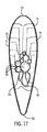
図17は、本発明の実施形態に従った、図3の17−17線に沿った、矢印方向に見た、フェアリングの上面断面図である。 FIG. 17 is a top sectional view of the fairing as seen in the direction of the arrow along lines 17-17 of FIG. 3, according to an embodiment of the present invention.
図18は、本発明の実施形態に従った、図4の18−18線に沿った、矢印方向に見た、フェアリングの底面断面図である。 FIG. 18 is a cross-sectional view of the bottom surface of the fairing as seen in the direction of the arrow along lines 18-18 of FIG. 4, according to an embodiment of the present invention.
図19は、本発明の別の実施形態に従った一体化ドレインマスト構造の斜視図であり、具体的にはフェアリングの右側部に流体排出口がない状態を示している。 FIG. 19 is a perspective view of an integrated drain mast structure according to another embodiment of the present invention, specifically showing a state in which there is no fluid discharge port on the right side portion of the fairing.
図20は、図19の実施形態に従った一体化ドレインマスト構造の斜視図であり、具体的には、フェアリングの左側部にすべての流体排出口が位置する状態を示している。 FIG. 20 is a perspective view of the integrated drain mast structure according to the embodiment of FIG. 19, specifically, showing a state in which all fluid discharge ports are located on the left side portion of the fairing.
図21は、図19および20の実施形態に従ったフェアリングの後方立面図である。 FIG. 21 is a rear elevation view of the fairing according to the embodiments of FIGS. 19 and 20.
図22は、図19および20の実施形態に従ったフェアリングの前方立面図である。 FIG. 22 is a front elevation view of the fairing according to the embodiments of FIGS. 19 and 20.
図23は、図19および20の実施形態に従ったフェアリングの左側立面図である。 FIG. 23 is a left elevation view of the fairing according to the embodiments of FIGS. 19 and 20.
図24は、図19および20の実施形態に従ったフェアリングの底面図である。 FIG. 24 is a bottom view of the fairing according to the embodiments of FIGS. 19 and 20.
図25は、図19から24の実施形態に従った、図21の25−25線に沿った、矢印方向に見た、フェアリングの上面断面図である。 FIG. 25 is a top sectional view of the fairing as seen in the direction of the arrow along lines 25-25 of FIG. 21 according to the embodiments of FIGS. 19 to 24.
図26は、図19から24の実施形態に従った、図22の26−26線に沿った、矢印方向に見た、フェアリングの底面断面図である。 FIG. 26 is a cross-sectional view of the bottom surface of the fairing as seen in the direction of the arrow along lines 26-26 of FIG. 22, according to the embodiments of FIGS. 19 to 24.
図27は、本発明の別の実施形態に従った、図23の27−27線に沿った、矢印方向に見た、フェアリングの後方立面断面図である。 FIG. 27 is a rear elevation cross-sectional view of the fairing as seen in the direction of the arrow along lines 27-27 of FIG. 23, according to another embodiment of the present invention.
図28は、図19に従った一体化ドレインマスト構造の右側拡大透視図であり、具体的には、フェアリングの右側部に流体排出口がない状態を示している。 FIG. 28 is a right-side enlarged perspective view of the integrated drain mast structure according to FIG. 19, specifically, showing a state in which there is no fluid discharge port on the right side of the fairing.
図29は、図20の実施形態に従った一体化ドレインマスト構造の左側拡大透視図であり、具体的には、フェアリングの左側部に流体排出口が存在する状態を示している。 FIG. 29 is a left enlarged perspective view of the integrated drain mast structure according to the embodiment of FIG. 20, specifically, showing a state in which a fluid discharge port exists on the left side portion of the fairing.
本発明の複数の好適な実施形態が、付随する図面を参照しながら、以下に説明される。他の例では、説明を不必要に不明瞭にしないために、よく知られた方法および構造は詳細に説明されていない。本明細書で説明される実施形態は、本発明を説明および解説するためのみに提供され、本発明に限定を行うものではないことを認識すべきである。 A plurality of preferred embodiments of the present invention will be described below with reference to the accompanying drawings. In other examples, well-known methods and structures are not described in detail so as not to unnecessarily obscure the description. It should be recognized that the embodiments described herein are provided solely for the purpose of explaining and explaining the invention and are not intended to limit the invention.
図1および図2は、本発明の一体化された設計のマスト構造40の第1の実施形態を示しており、具体的には、軽量の自立式チューブセクション50およびフェアリング60が図示されている。チューブセクション50は、航空機エンジンまたは胴体によって包囲された空間内に据え付けられることが意図されている。使用時、航空機のエンジンカウルの底部で、フェアリング60が気流中に位置するように、航空機のエンジンカウルを通って延在する。チューブセクション50は、チューブセクション50の上端部51から下端部52に延在し、一般に整列された複数の流体経路55(図5)を含む単一構造を備えている。実質的に空気力学的なフェアリング60は、複数のフェアリング流体経路90を含み(図14−18)、各フェアリング流体経路90は、チューブセクリョン50の対応する流体経路55と動作可能に流体連結している。フェアリング60は、前方面61と、後方面62と、右側壁部63Rおよび左側壁部63Lに沿って配置される流体排出口70とを含んでいる。フェアリング取付フランジ64が図1および2に示されている。チューブセクション50およびフェアリング60は、単一の一体化構造を備える。本明細書に図示される本発明の実施形態は、フェアリング60を、実質的にティアドロップ形状を有するように描いているものの、他の空気力学的形状も本発明の範囲内であるとみなされる。さらに、本発明の一実施形態では、チューブセクションの振動および他の外力に対する構造抵抗をさらに強化する、凹部すなわち「砂時計」形状を創出するために、隣接する、チューブセクションの上端部に向かう流体経路と、チューブセクションの下端部に向かう流体経路とを分離している周壁が、チューブセクション50’で示されるように、上記部分の間の領域における、隣接する流体経路を分離する各周壁よりも厚くなっている。
1 and 2 show a first embodiment of the integrated
本発明の好適な実施形態によれば、一体化ドレインマスト構造40は、コンポーネントの数を最小化し、支持用マスト、ブラケットおよび締め具の必要性を省き、別の特定の航空機エンジンまたは胴体コンポーネントによって発生される振動および外力に耐え、容易かつ迅速に据え付け可能な、自立式で軽量の一体構造を提供するために付加的に製造されることが意図されている。具体的には、チューブセクション50およびフェアリング60は、チタンTi−6A1−4V(グレード5)、アルミニウム、またはクロムおよび鉄を含むニッケル合金であるInconel(インコネル、登録商標)といった金属から付加的に製造されることが好ましい。このように、付加的に製造された一体化ドレインマスト構造40は、先行技術の従来設計と比較して、33%もの重量を減らすと推定されている。
According to a preferred embodiment of the invention, the integrated
流体導管80aから80j(集合的に流体導管80と呼ばれる)は、チューブセクション50の上端部53で各流体経路に接続されている。流体導管80aから80jの最上端部は、コネクタ82のようなコネクタを介して、航空機エンジンコンポーネントと関連づいた1または複数の流体源と接続されるように構成されている。
図3および図4は、それぞれ、フェアリング60の後方立面図および前方立面図である。図1に示されるように、フェアリング60は、実質的な鈍端形状または平坦形状であってもよい後方面62を含んでいる。その代わりに、図11に図示されているように、後方面62は実質的に丸みを帯びた形状またはテーパ状形状であってもよい。前方面61は、一般には曲線状かつ空気力学的形状である。
3 and 4 are a rear elevation and a front elevation of the fairing 60, respectively. As shown in FIG. 1, the fairing 60 includes a
図5に示されるように、各流体経路55は、自立式チューブセクション50の全長において実質的に等しい肉厚範囲である周壁56を有し、各流体経路55の周壁の少なくとも一部は、他の整列した流体経路55の少なくとも1つの周壁56と共有されている。各流体経路の周壁は、内壁57および外面58を含んでいる。よって、この自立式ドレインチューブセクション40は、従来技術の設計で使用される、個別のドレインチューブおよび関連づいた支持構造、ブラケットおよび取付ハードウェアに取って代わる。チューブセクション50は、10の様々な内径の流体経路55を有することが図示されており、各流体経路55は、少なくとも2つの他の隣接する整列した流体経路と共有する周壁56を有する。個々の流体経路55は、特定の流体の排液ニーズの構成により異なる。図示される実施形態は、10の流体経路を含んでいるが、本発明は、具体的なエンジン、または胴体における応用に応じて、それよりも少ない、または多い数の流体経路を含んで構成されてもよい。図示される実施形態において、流体経路55は整列して構成されている。各経路55は、関連づけられたエンジンコンポーネントから生成される流体を格納するようサイズが定められているが、経路55および各周壁56の構成は、飛行中に、チューブ構造に対して1または複数の特定の方向から付加され得る振動および外力に耐えるように、必要に応じて構成され得る、剛性の自立式支持構造を提供する働きがあることが認識されるであろう。同様に、チューブセクション50の集合的な周囲形状、すなわち「外周」が、集合的な経路55の寸法的ニーズにのみ順応するように最小化される。
As shown in FIG. 5, each
図5および他の図面で図示される「共有された壁部」は、より少ない材料で形成されるとともに、追加的な、または別の支持ブラケットまたは取付具の必要性をさらに取り除いた、剛性な自立式構造の一連の経路55を提供することが認識されるであろう。チューブセクション50は、実質的に直線状セクションとして描かれているが、チューブセクション50は、エンジンまたは胴体コンポーネントの据え付けおよび/または排液のニーズに順応するように、必要に応じて角度をつけて、または曲線状に形成されてもよい。
The "shared wall" illustrated in FIG. 5 and other drawings is rigid, made of less material and further eliminating the need for additional or separate support brackets or fittings. It will be recognized that it provides a series of
図3、4、6−9で開示されているように、1つの好適な実施形態では、流体排出口70が、フェアリング60の両方の側部で、底部67から頂部66にかけて、および、前縁61から後縁62にかけて、斜め方向に互い違いの配置(スタッガード・ダイアゴナル配列、staggered diagonal arrangement)で、フェアリング60の右側部63Rおよび左側部63Lの両方に配置されている。フェアリング60の左右両方の側に沿って、斜め方向に互い違いの配置で流体排出口70を配置することにより、単一の排出口からの漏出が、矢印Aの方向に、下方に滴り落ちることを防止し、さらに、排出口70が単に垂直配置である場合に発生しうる、別の流体排出口への流入の可能性を防止する。さらに、頂部66から底部65にかけて、流体排出口70の位置を互い違いにすることで、いずれかの排出口からの流体漏出を検知し、他の排出口70からの流体漏出と見分ける性能をさらに拡張できる。具体的には、排出口70から発生する流体漏出は、航空機が飛行中、矢印Bで示されるように、フェアリング60の後縁62に向かって吹き飛ばされる。航空機が静止している間に排出口70から発生する流体漏出は、多くの場合、矢印Aの方向に、下方に向かって滴り落ち、その際、特定の1つの流体排出口70に戻って追跡可能な線または筋を残す。従って、図示された構成は、どの流体排出口70から1または複数の流体が発生したか、また、どのエンジンまたは胴体コンポーネントにメンテナンスまたは修理が必要か、検出する性能を拡張している。
As disclosed in FIGS. 3, 4, 6-9, in one preferred embodiment,
図6−9で強調されているように、1または複数の流体が漏出している可能性がある流体排出口70を検出する性能をさらに拡張するために、フェアリング60の左右両面63Rおよび63Rから外側方向に突出した流体用リッジ71が備え付けられている。具体的には、流体用リッジ71は、視覚検査でより容易に検出可能となるように、流体排出口70から発生し得る、ごく少量の流体の収集を拡充するのに役立つ。
As highlighted in FIG. 6-9, the left and
本発明のこの実施形態では、流体用リッジ71は、各流体排出口70の各下縁(下方エッジ)74の直下に位置し、フェアリング60の後方面に向かって延在している。各流体用リッジは、各流体排出口70の前縁73に沿って延在する前方セクション70aをさらに含んでいる。図14で示される別実施形態では、各流体用リッジ71は、70bで、各流体排出口70の上方に伸びる(スイープする)リッジに向かって、各流体排出口70の前縁73に沿って、さらに延在してもよく、流体の収集をさらに拡充するとともに、どの排出口から漏出が起こったか検出する性能、および、メンテナンスが必要な航空機エンジンコンポーネントを特定する性能を妨げ得る、隣接するリッジまたは流体排出口に流れる流体を防止する。流体用リッジ71は、実質的な水平方向か、あるいは空気力学的な、下方向に角度がついた向きであってもよい。本発明の別の実施形態では、1または複数の流体排出口70cは、図8に示されるような空気力学的形状であってもよい。
In this embodiment of the present invention, the
図8および9はフェアリング60のさらなる実施形態を具体的に示しており、各流体排出口70の前縁からフェアリング60の後方面62に向かって、チャネル75が延在しており、それによって、任意の単一の流体排出口70から発生し得るごく少量の流体の収集および保持を促進し、漏出流体を視覚的に検出する性能、および、点検またはメンテナンスを必要とする関連づけられたエンジンまたは胴体コンポーネントを視覚的に特定する性能を拡張する。ある実施形態では、各排出口70に関連付けられたエンジンコンポーネントまたはシステムを具体的に検出および特定するために、独自の印、すなわちコード76が隣接する各流体排出口70に形成されてもよい。
8 and 9 specifically illustrates a further embodiment of the fairing 60, wherein the
図10および11は、本発明の一体化ドレインマスト構造の一実施形態の上面図および底面図であり、流体排出口70がフェアリング60の左側部63Lおよび右側部63Rの両方に備わっている。図10は、流体導管が接続される航空機エンジンまたは胴体に近接して配置された、自由端を有する流体導管80の構成を示している。流体導管80は、型によって一般に位置が異なる航空機エンジンまたは胴体を格納またはそれらに接続するように、必要に応じて別の構造で配置されてもよいことは認識されるであろう。さらに、排水のために接続される各コンポーネントおよび関連する流体の特性やタイプに応じて、可変直径の流体導管が使用されてもよい。本発明の一実施形態では、流体導管80は、直径1/4インチ(0.635cm)から3/4インチ(1.905cm)の範囲である。図11は、空気力学的形状のフェアリング60、および、前方面61および後方面62、ならびに、フェアリング60の左側部63Lおよび右側部63R上の流体用リッジ70の位置71を示している。航空機が空中を移動する際、1または複数の流体排出口からの流体漏出は、フェアリング60の後縁62方向に押し付けられることは認識されるであろう。
10 and 11 are a top view and a bottom view of an embodiment of the integrated drain mast structure of the present invention, in which a
図12は、分岐セクション53を示したチューブセクション50の頂部51の側部立面図である。図示されているように、各経路55の外側の周壁56は、各経路の周壁56がもはや互いに共有されないように、チューブセクション50の中心軸から外側方向に延在している。図13に示されるように、各第1端部の最上端は、流体導管80を入れ子状に伸縮自在に受けるのに使用されるカラー54を含む。チューブセクション50の上端部の分岐セクション53における、外に広がった構成は、例えば、ろう付け、溶接、またはねじ切りなどの機械的結合によって、個々の流体導管80aから80jと、各流体導管経路55との拘束接続を容易にする役割を果たす。この構成は、各エンジンまたは胴体コンポーネントに位置する上端部から、それぞれがチューブセクション50の各流体経路と結合する下端部へと各流体導管80を経路決めすることをさらに支援および最適化する。
FIG. 12 is a side elevation view of the top 51 of the
図14はフェアリング60の右側部63Rの拡大透視図である。フェアリング60は、前方面61および後方面62を含み、この実施形態では、一般にテーパ状または丸みを帯びた構成をしている。
FIG. 14 is an enlarged perspective view of the
フェアリング60は、チューブセクション50の一般に整列された複数の流体経路の各経路が、各フェアリングドレインチューブ90(図16)に接続および流体連結するように、チューブセクション50と一体的に形成されており、当該フェアリングドレインチューブ90は、フェアリング60の左側部63Lおよび右側部63Rの外側面上に形成された各流体排出口70に延びている。チューブセクション50およびフェアリング60は、単一の一体化された均一構造を形成するように付加的に製造されることが好ましい。フェアリング60は、フェアリングフランジ64およびフェアリング流体経路90を含んでいる。本発明によると、フェアリング60は、流体経路90および排出口70が形成される実質的に剛性の構成を備えておらず、その代わりに、図16−18に見られる空隙65の存在によって確認されるように、実質的に軽量の中空構造を備えている。フェアリングフランジ64は、実質的に同一平面上の配置で、エンジンカウルまたは胴体の外側面に固定される。図14および15は、フェアリング60の右側および左側の両方に、先述の流体用リッジ71をそれぞれが有する流体排出口70が位置する、本発明の一実施形態を示している。
The fairing 60 is formed integrally with the
図16は、フェアリング60の断面視であり、図6の16−16線でのチューブセクション50の一部を示している。図5に示される各流体経路55の断面は、一般に略円形断面であるが、それぞれの対応するフェアリング流体ドレインチューブの断面形状は、必ずしも円形断面でなくてもいいことが認識されるであろう。各フェアリング流体ドレインチューブが実質的な垂直方向から実質的な水平方向に移行する際、具体的には、先述のとおり、フェアリング60の各側部に沿った各流体排出口70の互い違いの配置を実現するように経路決めする際に、円形断面形状が変更されてもよい。図16は、フェアリング60の構成と、内部に位置するフェアリング流体ドレインチューブ90と、フェアリング60を画定する内部空間内の空隙65の存在とをさらに示しており、これらはすべて質量を最小限に抑え、顕著な軽量化を実現することを目的としている。
FIG. 16 is a cross-sectional view of the fairing 60, showing a portion of the
図17および18は、それぞれ、図3の17−17線、図4の18−18線における断面図である。具体的には、図17は、フェアリング流体経路90がチューブセクション流体経路55からフェアリング60に向かって移行する際の、フェアリング流体経路90の最上端部の実質的に垂直な部分を示している。最上端部に位置する2つの対抗する流体排出口70に関連づけられたフェアリング流体ドレイン経路90は、これら2つの経路の、外側の排出口の向きへの移行を反映して、実質的に非円形断面を有するように示されている。各フェアリング流体ドレインチューブ90の断面積は、一般に非円形断面を有しているが、それらが対応する流体経路55の断面積と実質的に等しい。図16にさらに示されているように、各フェアリング流体経路90がそれぞれの流体排出口70に経路決めし、もはや壁部を共有しない状態になる際に、各フェアリング流体経路90は、他の隣接するフェアリング流体経路90からそれぞれが分離する、実質的に等しい厚さ範囲の周囲面92を有する。図18は、フェアリング60内の複数のフェアリング流体経路90および配置および配向、おならびに、フェアリング60の反対側を向く側部63Lおよび63R上のそれらの各流体排出口70の位置をさらに示している。
17 and 18 are cross-sectional views taken along the line 17-17 of FIG. 3 and line 18-18 of FIG. 4, respectively. Specifically, FIG. 17 shows a substantially vertical portion of the topmost end of the fairing
図19−29は、本発明の一体化ドレインマスト構造の別の実施形態を示しており、航空機を点検する地上要員が、誤ってフェアリング110の片側のみを点検し、視覚に入らないフェアリング側部の流体排出口120からの流体漏出を見落としうるリスクを最小限に抑えるため、すべての流体排出口120がフェアリング110の片側に位置している。先述の実施形態と共通する要素には、同一の参照番号が振られている。
FIG. 19-29 shows another embodiment of the integrated drain mast structure of the present invention, in which a ground personnel inspecting an aircraft accidentally inspects only one side of the
図19および20は、本発明の一体化ドレインマスト構造の別の実施形態を示しており、すべての流体排出口120がフェアリング110の片側113Lにのみ位置している。実質的に空気力学的なフェアリング110は、前方面111、後方面112、左側部113Lおよび右側部113Rをそれぞれ含む。フェアリング110は取付フランジ114をさらに含み、当該取付フランジ114は、一体化ドレインマスト構造の航空機のエンジンカウルまたは胴体への取り付けを容易にする。図21−23はフェアリング110の、別の実施形態の前後および左側の立面図を示している。
19 and 20 show another embodiment of the integrated drain mast structure of the present invention, with all
図21−23,28,29で開示されるように、流体排出口120は、フェアリング110の底部117から頂部116、および前縁111から後縁112にかけて、斜め方向の互い違いの配置で、フェアリング110の左側部113Lにのみ配置されている。フェアリング110の左側部113Lのみに、斜め方向に互い違いに流体排出口120を配置することにより、単一の排出口からの漏出が、矢印Aの方向に、下方に滴り落ちることを防止し、さらに、排出口120が単に垂直配置である場合に発生し得る、別の流体排出口への流入の可能性を防止する。さらに、底部117から頂部116および前縁111から後縁112にかけて、流体排出口120の位置を交互にすることで、いずれか1つの排出口120からの流体漏出を検知し、他の排出口120からの流体漏出と見分ける性能をさらに拡張でき、このことは、多数の排出口120が必要な場合に、特に有益である。具体的には、排出口120から発生する流体漏出は、航空機が飛行中、矢印Bで示されるように、フェアリング120の後縁112に向かって吹き飛ばされる。航空機が静止している間に排出口120から発生する流体漏出は、多くの場合、矢印Aの方向に、下方に向かって滴り落ち、その際、特定の1つの流体排出口120に戻って追跡可能な線または筋を残す。従って、図示された構成は、どの流体排出口120から、1または複数の流体が発生したか、また、どのエンジンまたは胴体コンポーネントにメンテナンスまたは修理が必要か、検出する性能を拡張している。
As disclosed in FIGS. 21-23, 28, 29, the
どの流体排出口120から1または複数の流体が漏出したかを検出する性能をさらに拡張するために、流体用リッジ121がフェアリング120の左側部63Lから外側方向に突出しており、より容易に視覚検査で検出可能となるように、流体排出口120から発生し得る、ごく少量の流体の収集を拡充するよう機能する。先の実施形態でも開示されているように、流体用リッジ121は、各流体排出口120の各下方端118の直下に位置し、フェアリング120の後方面に向かって延在している。各流体用リッジ121は、各流体排出口120の前縁119に沿って延在する前方セクション110aをさらに含んでいる。別の実施形態では、各流体用リッジ121は、各流体排出口120の上方端部に向かう突起延長部110bで、各流体排出口120の前縁に沿って、さらに延在してもよく、流体の収集をさらに拡充するとともに、どの排出口から漏出が起こったか検出する性能、および、メンテナンスが必要な航空機エンジンコンポーネントを特定する性能を妨げ得る、隣接するリッジまたは流体排出口に流れる流体を防止する。ある単体の流体排出口70から発生し得るごく少量の流体の収集および保持を促進し、漏出流体を視覚的に検出する性能、および、点検またはメンテナンスを必要とする関連づけられたエンジンまたは胴体コンポーネントを視覚的に特定する性能を拡張するために、フェアリング110は、各流体排出口120の前縁からフェアリング110の後方面に向かって延在するチャネルを追加的に含んでもよい(図8および図9)。
To further enhance the ability to detect which
図24は、図19および図20の一体化ドレインマスト構造の別の実施形態の底面図であり、フェアリング110の左側部113Lのみに流体用リッジ121が位置している。
FIG. 24 is a bottom view of another embodiment of the integrated drain mast structure of FIGS. 19 and 20, in which the
図25および図26は、フェアリング110の断面図であり、フェアリング流体経路130の垂直方向の整列部分が、チューブセクションの流体経路155から、フェアリング110に移行し、流体排出口120で左側部113Lから脱出する際の、フェアリング流体経路130の垂直方向の整列部分を図示している。図26はフェアリング110内のフェアリング流体経路130の配置および向き、ならびに、フェアリング110の113Lの側に位置する各流体排出口120をさらに図示している。
25 and 26 are cross-sectional views of the fairing 110, where the vertically aligned portion of the fairing
図27は、フェアリング110の断面であって、図23の27−27線のチューブセクション155の一部であり、フェアリング110の構造、内部に位置するフェアリング流体チューブ130、および、フェアリング110を画定する内部空間の空隙115の存在を示している。
27 is a cross section of the fairing 110, which is part of the
図28および図29は、フェアリング110の底部117から頂部116、および前縁111から後縁112にかけて、斜め方向の互い違いの配置で、フェアリング110の左側部113Lにのみ配置された流体排出口120を開示している。先述のとおり、流体排出口120の位置を斜め方向の互い違いの配置にすることで、いずれか1つの排出口120からの流体漏出を検知し、他の排出口120からの流体漏出と見分ける性能をさらに拡張でき、多数の排出口120が必要な場合に、特に有益である。
28 and 29 show a fluid discharge port arranged only on the
本発明は、航空機全体における据え付けを容易化および促進するために、完全に一体化したドレインマスト構造40、100、および、関連する流体導管の準備組み立てを可能にする。
The present invention allows the pre-assembly of fully integrated
本発明は航空機エンジンコンポーネントから排出される流体の文脈において強調されているが、本発明は、客室の内部および外部両方における、航空機の加圧される胴体内に配置されたコンポーネントおよびシステムから流体を排出または放出するために、同様に適用されてもよい。例えば、本明細書で開示される本発明は、航空機のシンク排水管、および/または貯氷庫からの水を収集および排水するように構成されてもよい。 Although the invention is emphasized in the context of fluids expelled from aircraft engine components, the invention draws fluids from components and systems located inside the pressurized fuselage of an aircraft, both inside and outside the cabin. It may be applied as well for discharge or release. For example, the invention disclosed herein may be configured to collect and drain water from an aircraft sink drain and / or ice storage.
本明細書で様々な態様および実施が開示されているが、他の態様および実施が当業者にとって明らかであろう。本明細書で開示された様々な態様、実施形態および実施は例示を目的としており、限定を意図しておらず、真の特許請求の範囲は、以下の請求項によって示され、かかる請求項がその権利を付与する同等物の完全な特許請求の範囲も含まれる。さらに、本明細書で使用される専門用語は、特定の実施を説明することのみを目的とし、限定を意図するものではない。本発明の趣旨から逸脱しない修正、同等物との置換、または実施形態の改良は本発明の権利保護の範囲内であるとみなされるべきである。 Various aspects and practices are disclosed herein, but other aspects and practices will be apparent to those skilled in the art. The various aspects, embodiments and practices disclosed herein are for purposes of illustration only and are not intended to be limiting, and the true claims are set forth by the following claims. It also includes the full claims of the equivalent granting that right. Moreover, the terminology used herein is for the sole purpose of describing a particular practice and is not intended to be limiting. Modifications, replacements with equivalents, or improvements to embodiments that do not deviate from the spirit of the invention should be considered within the scope of protection of the rights of the invention.
Claims (25)
航空機内に配置されるための自立式チューブセクションであって、前記チューブセクションは、前記チューブセクションの上端部から前記チューブセクションの下端部に向かって延在する一般に整列した複数の流体経路を含む、自立式チューブセクションを備え、
各流体経路は、周囲面を有し、前記周囲面の少なくとも一部は、少なくとも1つの他の整列した流体経路の周囲面の一部を共有しており、
前記流体経路のそれぞれは、前記自立式チューブセクション全体で、それぞれの横位置において実質的に同一の厚さを有するそれぞれの周壁によって、隣接する流体経路から分離され、
前記チューブセクション内の各流体経路の前記上端部は、1または複数の流体源と、流体連結するように配置されて構成され、
気流内に配置されるとともに、複数のフェアリング流体経路を含むための実質的に空気力学的なフェアリングを備え、各フェアリング流体経路は、その上端部で、前記チューブセクションのそれぞれの流体経路の下端部に、および、その下端部で、前記フェアリングに位置するそれぞれの流体排出口に接続され、
前記自立式チューブセクションの断面形状は、前記チューブセクションに沿った各横位置での断面形状を最小化するように、前一般に整列した複数の流体経路およびそれらの各周壁の合計幅と実質的に対応しており、
前記チューブセクションおよび前記フェアリングは単一の一体化構造を備える、一体化ドレインマスト構造。 An integrated drain mast structure that drains fluid from the aircraft housing
A self-supporting tube section for placement in an aircraft, said tube section comprising a plurality of generally aligned fluid paths extending from the upper end of the tube section to the lower end of the tube section. Equipped with a free-standing tube section
Each fluid path has a perimeter, at least a portion of said perimeter, sharing a portion of the perimeter of at least one other aligned fluid path.
Each of the fluid paths is separated from the adjacent fluid path by a peripheral wall having substantially the same thickness at each lateral position throughout the free-standing tube section.
The upper end of each fluid path in the tube section is configured to be fluid connected to one or more fluid sources.
Along with being placed in the air stream, each fairing fluid path has a substantially aerodynamic fairing to include multiple fairing fluid paths, each fairing fluid path at its upper end, with a respective fluid path in the tube section. At the lower end of the fairing and at its lower end, it is connected to each fluid outlet located at the fairing.
The cross-sectional shape of the free-standing tube section is substantially the total width of the pre-generally aligned fluid paths and their respective peripheral walls so as to minimize the cross-sectional shape at each lateral position along the tube section. It corresponds,
An integrated drain mast structure, wherein the tube section and the fairing have a single integrated structure.
航空機エンジン内に位置するとともに、エンジンカウルによって包囲されるための自立式チューブセクションであって、前記チューブセクションは、前記チューブセクションの上端部から下端部に向かって延在する一般に整列した複数の流体経路を含む、自立式チューブセクションを備え、
各流体経路は周囲面を有し、前記周囲面の少なくとも一部は、隣接し、整列した流体経路の周囲面の一部を共有し、各流体経路の上端部は、1または複数のタービンエンジンコンポーネントと流体接続するように構成され、
前記航空機エンジンカウルの外面から延在する、実質的に空気力学的なフェアリングであって、前記フェアリングは、一端でそれぞれの流体経路に接続され、かつ、他端で前記フェアリングに位置する複数の流体排出口のそれぞれに接続された、フェアリングを備え、
前記自立式チューブセクションの断面形状は、前記チューブセクションに沿った各位置での断面形状を最小化するように、前記一般に整列した複数の流体経路、および、それらのそれぞれの横方向の周壁の合計幅に実質的に対応する、ドレインマスト。 A drain mast that drains fluid from an aircraft turbine engine
A self-supporting tube section that is located within an aircraft engine and is to be surrounded by an engine cowl, the tube section being a generally aligned fluid extending from the upper end to the lower end of the tube section. With a free-standing tube section, including pathways,
Each fluid path has a peripheral surface, at least a portion of said peripheral surface shares a portion of the peripheral surface of adjacent, aligned fluid paths, and the top edge of each fluid path is one or more turbine engines. Configured to fluidly connect with components
A substantially aerodynamic fairing extending from the outer surface of the aircraft engine cowl, the fairing being connected to each fluid path at one end and located at the fairing at the other end. With fairings connected to each of the multiple fluid outlets,
The cross-sectional shape of the free-standing tube section is the sum of the generally aligned fluid paths and their respective lateral peripheral walls so as to minimize the cross-sectional shape at each position along the tube section. A drain mast that substantially corresponds to the width.
Applications Claiming Priority (3)
| Application Number | Priority Date | Filing Date | Title |
|---|---|---|---|
| US15/917,269 | 2018-03-09 | ||
| US15/917,269 US10717514B2 (en) | 2018-03-09 | 2018-03-09 | Integrated drain mast structure |
| PCT/EP2019/050452 WO2019170302A1 (en) | 2018-03-09 | 2019-01-09 | Integrated drain mast structure |
Publications (2)
| Publication Number | Publication Date |
|---|---|
| JP2021510651A JP2021510651A (en) | 2021-04-30 |
| JP6905642B2 true JP6905642B2 (en) | 2021-07-21 |
Family
ID=65036763
Family Applications (1)
| Application Number | Title | Priority Date | Filing Date |
|---|---|---|---|
| JP2020547050A Active JP6905642B2 (en) | 2018-03-09 | 2019-01-09 | Integrated drain mast structure |
Country Status (8)
| Country | Link |
|---|---|
| US (1) | US10717514B2 (en) |
| EP (1) | EP3762291B1 (en) |
| JP (1) | JP6905642B2 (en) |
| KR (1) | KR102342428B1 (en) |
| CN (1) | CN111788116B (en) |
| CA (1) | CA3088746C (en) |
| RU (1) | RU2767646C1 (en) |
| WO (1) | WO2019170302A1 (en) |
Families Citing this family (3)
| Publication number | Priority date | Publication date | Assignee | Title |
|---|---|---|---|---|
| US11186354B2 (en) * | 2019-05-06 | 2021-11-30 | Rohr, Inc. | Unitary drain mast |
| US11268637B2 (en) | 2019-11-05 | 2022-03-08 | Rohr, Inc. | Drain mast seal assembly with seal wedge(s) |
| FR3118945B1 (en) * | 2021-01-19 | 2024-02-16 | Safran Aircraft Engines | REDUCED COMPACT DRAINAGE MAST FOR AN AIRCRAFT TURBOMACHINE NACELLE |
Family Cites Families (29)
| Publication number | Priority date | Publication date | Assignee | Title |
|---|---|---|---|---|
| US2908037A (en) | 1954-03-24 | 1959-10-13 | Multiple Extrusions Inc | Making multiple tube structures by extrusion |
| GB1205514A (en) * | 1968-06-20 | 1970-09-16 | United Aircraft Canada | Centrifugal and mixed flow discharge apparatus |
| US5552576A (en) * | 1992-02-21 | 1996-09-03 | The Bf Goodrich Company | Modular drainmast for aircraft |
| US5290996A (en) * | 1992-02-21 | 1994-03-01 | The B. F. Goodrich Company | Modular drainmast for aircraft |
| WO2002036426A2 (en) * | 2000-08-18 | 2002-05-10 | Goodrich Corporation | Aircraft drainmast assembly with lightning protection |
| GB2376269A (en) * | 2001-06-08 | 2002-12-11 | Rolls Royce Plc | A gas turbine engine breather outlet |
| US6578361B1 (en) * | 2001-08-30 | 2003-06-17 | General Electric Co. | Methods and apparatus for determining engine cavity leakage |
| FR2866316B1 (en) * | 2004-01-26 | 2007-01-26 | Goodrich Corp | DRAIN MAT ASSEMBLY FOR AIRCRAFT |
| DE102004036296B4 (en) * | 2004-07-27 | 2010-04-01 | Airbus Deutschland Gmbh | Draining device for an aircraft |
| US20070298277A1 (en) * | 2006-06-21 | 2007-12-27 | General Electric Company | Metal phosphate coating for oxidation resistance |
| FR2910888B1 (en) * | 2007-01-03 | 2013-08-23 | Airbus France | DEVICE FOR RECOVERING FLUID. |
| GB2446147B (en) * | 2007-01-30 | 2009-02-18 | Rolls Royce Plc | Aeroengine drain assembly |
| GB2452026B (en) | 2007-07-27 | 2010-05-05 | Assystem | Instrumentation rake and aerofoil having instrumentation elements and method of manufacture therefor |
| US20090133376A1 (en) * | 2007-11-28 | 2009-05-28 | Zysman Steven H | Combined gearbox breather and drain mast for jet aircraft engine |
| DE102008025869A1 (en) | 2008-05-31 | 2009-12-03 | Mtu Aero Engines Gmbh | Measuring probe and method for producing a measuring probe |
| FR2952713B1 (en) | 2009-11-16 | 2014-01-03 | Snecma | PROCESS FOR MANUFACTURING A MEASURING COMB WITH MEASURING MEANS FOR MEASURING PARAMETERS IN AN EXPERIMENTAL TURBOJET AIR FLOW |
| US20110121137A1 (en) * | 2009-11-24 | 2011-05-26 | Electrofilm Manufacturing Company Llc | Method and apparatus for directing waste away from aircraft |
| CA2776213C (en) * | 2011-05-13 | 2020-07-14 | Goodrich Corporation | Drainmast for releasing water into an airstream of an aircraft |
| ES2614905T3 (en) * | 2012-01-26 | 2017-06-02 | Airbus Operations, S.L. | Drain mast of the auxiliary power unit compartment of an aircraft |
| US9759334B2 (en) | 2012-12-31 | 2017-09-12 | Vetco Gray Inc. | Gate valve arrangement including multi-valve stem and seat assemblies |
| EP2829469B1 (en) | 2013-07-22 | 2017-03-01 | Airbus Operations S.L. | Drainage mast of an aircraft compartment subjected to a negative pressure |
| US9315253B2 (en) | 2013-09-18 | 2016-04-19 | Goodrich Corporation | Drain masts |
| FR3014132B1 (en) * | 2013-12-04 | 2018-10-26 | Safran Aircraft Engines | DRAIN FLUID EVACUATION MAT FOR A PROPULSIVE ASSEMBLY |
| WO2015119792A1 (en) * | 2014-02-05 | 2015-08-13 | United Technologies Corporation | Integral instrumentation in additively manufactured components of gas turbine engines |
| FR3021028B1 (en) * | 2014-05-15 | 2016-06-24 | Dassault Aviat | DRAINAGE MAT AND METHOD THEREOF |
| US9453595B2 (en) | 2014-05-21 | 2016-09-27 | Honeywell International Inc. | Drain mast seal having segregated chambers |
| FR3039513B1 (en) | 2015-07-28 | 2017-09-01 | Thales Sa | PROCESS FOR THE ADDITIVE MANUFACTURE OF AERONAUTICAL EQUIPMENT |
| US9664542B2 (en) | 2015-08-20 | 2017-05-30 | Honeywell International Inc. | Systems and methods for additive manufacturing for air data probes |
| US10167741B2 (en) * | 2015-11-03 | 2019-01-01 | Rohr, Inc. | Nacelle fluid drain |
-
2018
- 2018-03-09 US US15/917,269 patent/US10717514B2/en active Active
-
2019
- 2019-01-09 CA CA3088746A patent/CA3088746C/en active Active
- 2019-01-09 RU RU2020123040A patent/RU2767646C1/en active
- 2019-01-09 JP JP2020547050A patent/JP6905642B2/en active Active
- 2019-01-09 EP EP19700869.1A patent/EP3762291B1/en active Active
- 2019-01-09 KR KR1020207023422A patent/KR102342428B1/en active Active
- 2019-01-09 WO PCT/EP2019/050452 patent/WO2019170302A1/en active Application Filing
- 2019-01-09 CN CN201980015667.XA patent/CN111788116B/en active Active
Also Published As
| Publication number | Publication date |
|---|---|
| RU2767646C1 (en) | 2022-03-18 |
| CN111788116B (en) | 2024-02-06 |
| KR20200106081A (en) | 2020-09-10 |
| US20190276131A1 (en) | 2019-09-12 |
| CA3088746C (en) | 2023-03-21 |
| WO2019170302A1 (en) | 2019-09-12 |
| US10717514B2 (en) | 2020-07-21 |
| BR112020014976A2 (en) | 2021-02-09 |
| EP3762291B1 (en) | 2024-03-06 |
| EP3762291A1 (en) | 2021-01-13 |
| CA3088746A1 (en) | 2019-09-12 |
| CN111788116A (en) | 2020-10-16 |
| KR102342428B1 (en) | 2021-12-27 |
| JP2021510651A (en) | 2021-04-30 |
Similar Documents
| Publication | Publication Date | Title |
|---|---|---|
| JP6905642B2 (en) | Integrated drain mast structure | |
| US8231142B2 (en) | Fluid conduit coupling with leakage detection | |
| EP1434931B1 (en) | Witness drain valve | |
| US20090133376A1 (en) | Combined gearbox breather and drain mast for jet aircraft engine | |
| US8893742B2 (en) | Double-skin nozzle system, junction system between two tube portions, and aircraft provided with such a system | |
| EP2947002B1 (en) | Drain mast seal having segregated chambers | |
| CN105793159A (en) | Device for retaining drained fluids for a propulsive assembly | |
| US10532802B2 (en) | Propulsion assembly comprising a box for retaining drained fluids | |
| US8394163B2 (en) | Conduit piece for the absorption of foreign bodies | |
| US9488301B2 (en) | Removable coupling device for coupling together two flexible pipes | |
| US11591935B2 (en) | Fluid drain system for an aircraft propulsion system | |
| BR112020014976B1 (en) | INTEGRATED DRAIN MAST STRUCTURE | |
| EP3073168B1 (en) | Double wall tube fitting with an integrated diagnostic port | |
| US10844971B2 (en) | Shrouded valve assembly | |
| US20170314696A1 (en) | Shrouded valve assembly | |
| US11186354B2 (en) | Unitary drain mast | |
| CN207688445U (en) | Compressor assembly and air-conditioning system |
Legal Events
| Date | Code | Title | Description |
|---|---|---|---|
| A621 | Written request for application examination |
Free format text: JAPANESE INTERMEDIATE CODE: A621 Effective date: 20200915 |
|
| A871 | Explanation of circumstances concerning accelerated examination |
Free format text: JAPANESE INTERMEDIATE CODE: A871 Effective date: 20200915 |
|
| A975 | Report on accelerated examination |
Free format text: JAPANESE INTERMEDIATE CODE: A971005 Effective date: 20210120 |
|
| A131 | Notification of reasons for refusal |
Free format text: JAPANESE INTERMEDIATE CODE: A131 Effective date: 20210316 |
|
| A521 | Request for written amendment filed |
Free format text: JAPANESE INTERMEDIATE CODE: A523 Effective date: 20210324 |
|
| TRDD | Decision of grant or rejection written | ||
| A01 | Written decision to grant a patent or to grant a registration (utility model) |
Free format text: JAPANESE INTERMEDIATE CODE: A01 Effective date: 20210601 |
|
| A61 | First payment of annual fees (during grant procedure) |
Free format text: JAPANESE INTERMEDIATE CODE: A61 Effective date: 20210625 |
|
| R150 | Certificate of patent or registration of utility model |
Ref document number: 6905642 Country of ref document: JP Free format text: JAPANESE INTERMEDIATE CODE: R150 |
|
| R250 | Receipt of annual fees |
Free format text: JAPANESE INTERMEDIATE CODE: R250 |