[go: up one dir, main page]

JP6884950B2 - Component mounting system - Google Patents

Component mounting system Download PDF

Info

Publication number
JP6884950B2
JP6884950B2 JP2017095178A JP2017095178A JP6884950B2 JP 6884950 B2 JP6884950 B2 JP 6884950B2 JP 2017095178 A JP2017095178 A JP 2017095178A JP 2017095178 A JP2017095178 A JP 2017095178A JP 6884950 B2 JP6884950 B2 JP 6884950B2
Authority
JP
Japan
Prior art keywords
feeder
supply unit
component mounting
unit
component
Prior art date
Legal status (The legal status is an assumption and is not a legal conclusion. Google has not performed a legal analysis and makes no representation as to the accuracy of the status listed.)
Active
Application number
JP2017095178A
Other languages
Japanese (ja)
Other versions
JP2018190944A (en
Inventor
英泰 ▲高▼宮
英泰 ▲高▼宮
Current Assignee (The listed assignees may be inaccurate. Google has not performed a legal analysis and makes no representation or warranty as to the accuracy of the list.)
Individual
Original Assignee
Individual
Priority date (The priority date is an assumption and is not a legal conclusion. Google has not performed a legal analysis and makes no representation as to the accuracy of the date listed.)
Filing date
Publication date
Application filed by Individual filed Critical Individual
Priority to JP2017095178A priority Critical patent/JP6884950B2/en
Publication of JP2018190944A publication Critical patent/JP2018190944A/en
Application granted granted Critical
Publication of JP6884950B2 publication Critical patent/JP6884950B2/en
Active legal-status Critical Current
Anticipated expiration legal-status Critical

Links

Images

Landscapes

  • Supply And Installment Of Electrical Components (AREA)

Description

本発明は、電子部品を基板に実装する部品実装システムに関する発明である。 The present invention relates to a component mounting system for mounting electronic components on a substrate.

従来、複数の部品が収容された部品供給ユニットから部品を採取して基板に実装する部品実装機において、部品供給ユニットを自動で交換可能なものが提案されている。例えば、特許文献1には、部品供給ユニットが着脱可能にセットされ、部品供給ユニットが供給した部品を実装対象物に実装する部品実装機を実装対象物の搬送方向に沿って複数並べて構成した部品実装ラインであって、部品供給ユニットを複数保管するユニット保管庫と、複数の部品実装機に取り付けられている部品供給ユニットとユニット保管庫に保管されている部品供給ユニットとを交換可能なユニット交換装置と、ユニット交換装置を制御する制御装置とを備え、ユニット保管庫は、複数の部品実装機と同じ並びに設置され、制御装置は、搬送方向に沿った所定の移動範囲を移動して部品供給ユニットの交換を行うようにユニット交換装置を制御する電子部品実装ラインが開示されている。 Conventionally, in a component mounting machine in which a component is collected from a component supply unit containing a plurality of components and mounted on a board, a component mounting machine in which the component supply unit can be automatically replaced has been proposed. For example, in Patent Document 1, a component supply unit is set to be detachably set, and a plurality of component mounting machines for mounting components supplied by the component supply unit on a mounting object are arranged side by side along a transport direction of the mounting object. Unit replacement that can replace the unit storage that stores multiple parts supply units on the mounting line, and the parts supply units that are mounted on multiple parts mounting machines and the parts supply units that are stored in the unit storage. A device and a control device for controlling a unit exchange device are provided, a unit storage is installed in the same arrangement as a plurality of component mounting machines, and the control device moves a predetermined movement range along a transport direction to supply components. An electronic component mounting line that controls a unit replacement device to replace a unit is disclosed.

国際公開WO2017/033268号公報International Publication WO2017 / 033268

特許文献1の電子部品実装ラインにおけるユニット交換装置は、ユニット保管庫と部品実装機の部品供給ユニットストックエリアとの間、ユニット保管庫と部品実装機の吸着作業エリアとの間、1台の部品実装機の部品供給ユニットストックエリアと吸着作業エリアとの間、他の部品実装機の部品供給ユニットストックエリアと吸着作業エリアとの間で、部品供給ユニット交換を行なう必要がある。この構成において、部品供給ユニットの交換作業が集中する場合や、部品供給ユニットの移動距離が長い場合、部品供給ユニットの交換待ちにより生産効率が低下する可能性がある。また、部品実装機の一部が引出せる構成の装置においては、トラブル等の原因により引出した装置の先に部品供給ユニットが移動できないため、生産効率が低下する可能性がある。 The unit replacement device in the electronic component mounting line of Patent Document 1 includes one component between the unit storage and the component supply unit stock area of the component mounting machine, and between the unit storage and the suction work area of the component mounting machine. It is necessary to replace the component supply unit between the component supply unit stock area and the suction work area of the mounting machine and between the component supply unit stock area and the suction work area of another component mounting machine. In this configuration, when the replacement work of the parts supply unit is concentrated or when the moving distance of the parts supply unit is long, the production efficiency may decrease due to the waiting for the replacement of the parts supply unit. Further, in a device having a configuration in which a part of the component mounting machine can be pulled out, the parts supply unit cannot move to the tip of the drawn device due to a cause such as trouble, so that the production efficiency may decrease.

本開示は、部品供給ユニット交換作業が集中する場合においても、生産効率の低下を防止可能な部品実装システムを提供することを主目的とする。 A main object of the present disclosure is to provide a component mounting system capable of preventing a decrease in production efficiency even when the component supply unit replacement work is concentrated.

本開示は、上述の主目的を達成するために以下の手段を採った。 The present disclosure has taken the following steps to achieve the above-mentioned main objectives.

本開示の部品実装システムは、部品供給ユニットが着脱可能にセットされ、前記部品供給ユニットが供給した部品を実装対象物に実装する部品実装機を前記実装対象物の搬送方向に沿って複数並べて構成した部品実装システムであって、複数の部品実装機と同じ並びに設置され、前記部品供給ユニットを複数保管するユニット保管庫と、前記部品実装機の部品吸着位置に部品を供給する複数の前記部品供給ユニットを並べて取り付ける吸着作業エリアと、前記吸着作業エリアの使用済みの部品供給ユニットと入れ替える次の部品供給ユニットを収納すると共に前記使用済みの部品供給ユニットを回収する部品供給ユニットストックエリアと、複数の部品実装機の前記部品供給ユニットストックエリアと前記ユニット保管庫との間でのみ前記部品供ユニットを交換可能な第1ユニット交換装置と、複数の部品実装機の前記吸着作業エリアと前記部品供給ユニットストックエリアとの間でのみ前記部品供給ユニットを交換可能な第2ユニット交換装置と、前記搬送方向に沿った所定の移動範囲を移動して、前記部品供給ユニットの交換を行うよう前記第1ユニット交換装置及び前記第2ユニット交換装置を制御する制御装置と、を備えたものである。 In the component mounting system of the present disclosure, a component supply unit is detachably set, and a plurality of component mounting machines for mounting the components supplied by the component supply unit on the mounting object are arranged side by side along the transport direction of the mounting object. A unit storage system that is installed in the same arrangement as a plurality of component mounting machines and stores a plurality of the component supply units, and a plurality of the component supply units that supply components to the component suction positions of the component mounting machine. A plurality of suction work areas for mounting units side by side, a parts supply unit stock area for accommodating the next parts supply unit to be replaced with the used parts supply unit in the suction work area, and collecting the used parts supply unit. A first unit replacement device capable of exchanging the component supply unit only between the component supply unit stock area of the component mounting machine and the unit storage, and the suction work area and the component supply unit of a plurality of component mounting machines. The second unit exchange device capable of exchanging the parts supply unit only with and from the stock area, and the first unit for exchanging the parts supply unit by moving a predetermined movement range along the transport direction. It is provided with an exchange device and a control device for controlling the second unit exchange device.

この部品実装システムは、第1ユニット交換装置が複数の部品実装機の部品供給ユニットストックエリアとユニット保管庫との間でのみ部品供給ユニット交換作業を行い、第2ユニット交換装置が複数の部品実装機の吸着作業エリアと部品供給ユニットストックエリアとの間でのみ部品供給ユニット交換作業を行うことができる。従って、この部品実装システムでは、異なる交換対象に対する部品供給ユニット交換の並行作業が可能となり、部品供給ユニット交換作業を、より適正に対処することができる。 In this component mounting system, the first unit replacement device performs component supply unit replacement work only between the component supply unit stock area of multiple component mounting machines and the unit storage , and the second unit replacement device mounts multiple components. The parts supply unit replacement work can be performed only between the suction work area of the machine and the parts supply unit stock area. Therefore, in this component mounting system, the component supply unit replacement work can be performed in parallel for different replacement targets, and the component supply unit replacement work can be dealt with more appropriately.

図1は部品実装システム10の構成の概略を示す構成図である。FIG. 1 is a configuration diagram showing an outline of the configuration of the component mounting system 10. 図2は部品実装機20の構成の概略を示す構成図である。FIG. 2 is a configuration diagram showing an outline of the configuration of the component mounting machine 20. 図3はフィーダ30の構成の概略を示す構成図である。FIG. 3 is a configuration diagram showing an outline of the configuration of the feeder 30. 図4は第2交換ロボット50の構成の概略を示す構成図である。FIG. 4 is a configuration diagram showing an outline of the configuration of the second exchange robot 50. 図5はフィーダ保管庫60の構成の概略を示す構成図である。FIG. 5 is a configuration diagram showing an outline of the configuration of the feeder storage 60. 図6は部品実装システム10の制御に関する構成図である。FIG. 6 is a configuration diagram relating to control of the component mounting system 10. 図7は保管エリア情報更新処理の一例を示すフローチャートである。FIG. 7 is a flowchart showing an example of the storage area information update process. 図8は保管エリア情報の一例を示す説明図である。FIG. 8 is an explanatory diagram showing an example of storage area information. 図9はフィーダ交換処理1の一例を示すフローチャートである。FIG. 9 is a flowchart showing an example of the feeder exchange process 1. 図10はフィーダ交換処理2の一例を示すフローチャートである。FIG. 10 is a flowchart showing an example of the feeder exchange process 2.

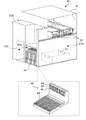
図1は部品実装システム10の構成の概略を示す構成図であり、図2は部品実装機20の構成の概略を示す構成図であり、図3はフィーダ30の構成の概略を示す構成図である。また、図4は第2交換ロボット50の構成の概略を示す構成図であり、図5はフィーダ保管庫60の構成の概略を示す構成図であり、図6は部品実装システム10の制御に関する構成図である。なお、図1の左右方向がX方向であり、前後方向がY方向であり、上下方向がZ方向である。 FIG. 1 is a configuration diagram showing an outline of the configuration of the component mounting system 10, FIG. 2 is a configuration diagram showing an outline of the configuration of the component mounting machine 20, and FIG. 3 is a configuration diagram showing an outline of the configuration of the feeder 30. is there. Further, FIG. 4 is a configuration diagram showing an outline of the configuration of the second exchange robot 50, FIG. 5 is a configuration diagram showing an outline of the configuration of the feeder storage 60, and FIG. 6 is a configuration related to control of the component mounting system 10. It is a figure. The left-right direction in FIG. 1 is the X direction, the front-back direction is the Y direction, and the up-down direction is the Z direction.

部品実装システム10は、図1に示すように、基板上に半田を印刷する印刷機12と、印刷された半田の状態を検査する印刷検査機14と、フィーダ30から供給された部品を基板に実装する複数の部品実装機20と、部品の実装状態を検査する実装検査機(図示省略)と、複数のフィーダ30を保管可能なフィーダ保管庫60と、ライン全体を管理する管理装置80などを備える。部品実装システム10では、印刷機12と印刷検査機14と複数の部品実装機20とが、この順番で基板の搬送方向(X方向)に並べて設置されている。また、フィーダ保管庫60は、部品実装システム10のライン内に組み込まれており、複数の部品実装機20のうち基板の搬送方向の最も上流側の部品実装機20と印刷検査機14との間に設置されている。即ち、フィーダ保管庫60は、最も上流側の部品実装機20よりも上流位置に設置されている。本実施形態では、作業者がフィーダ保管庫60にフィーダ30を補給したり、フィーダ保管庫60からフィーダ30を回収したりする。フィーダ保管庫60に対するフィーダ30の補給や回収を、フィーダ30の搬入出ともいう。 As shown in FIG. 1, the component mounting system 10 uses a printing machine 12 for printing solder on a substrate, a printing inspection machine 14 for inspecting the state of printed solder, and components supplied from a feeder 30 on the substrate. A plurality of component mounting machines 20 to be mounted, a mounting inspection machine (not shown) for inspecting the mounting state of components, a feeder storage 60 capable of storing a plurality of feeders 30, a management device 80 for managing the entire line, and the like. Be prepared. In the component mounting system 10, the printing machine 12, the printing inspection machine 14, and the plurality of component mounting machines 20 are installed side by side in the transfer direction (X direction) of the substrate in this order. Further, the feeder storage 60 is incorporated in the line of the component mounting system 10, and is located between the component mounting machine 20 on the most upstream side of the plurality of component mounting machines 20 in the substrate transport direction and the printing inspection machine 14. It is installed in. That is, the feeder storage 60 is installed at a position upstream of the component mounting machine 20 on the most upstream side. In the present embodiment, the worker replenishes the feeder storage 60 with the feeder 30 and collects the feeder 30 from the feeder storage 60. The supply and collection of the feeder 30 to the feeder storage 60 is also referred to as the loading and unloading of the feeder 30.

また、部品実装システム10は、複数の部品実装機20とフィーダ保管庫60との間でフィーダ30の自動交換を行う第1交換ロボット46と、複数の部品実装機の間でフィーダ30の自動交換を行う第2交換ロボット50と、を備える。第1交換ロボット46及び第2交換ロボット50は、複数の部品実装機20の前面およびフィーダ保管庫60の前面に基板の搬送方向(X方向)に対して平行に設けられたX軸レール18に沿って移動可能となっている。なお、図2や図5では、X軸レール18の図示を省略した。 Further, the component mounting system 10 automatically replaces the feeder 30 between the first replacement robot 46 that automatically replaces the feeder 30 between the plurality of component mounting machines 20 and the feeder storage 60, and the feeder 30 between the plurality of component mounting machines. A second exchange robot 50 for performing the above is provided. The first replacement robot 46 and the second replacement robot 50 are mounted on X-axis rails 18 provided parallel to the substrate transport direction (X direction) on the front surface of the plurality of component mounting machines 20 and the front surface of the feeder storage 60. It is possible to move along. In addition, in FIG. 2 and FIG. 5, the illustration of the X-axis rail 18 is omitted.

部品実装機20は、図2に示すように、基板SをX方向に搬送する基板搬送装置21と、フィーダ30が供給した部品を吸着する吸着ノズルを有するヘッド22と、ヘッド22をXY方向に移動させるヘッド移動機構23と、装置全体を制御する実装制御装置28(図6参照)とを備える。実装制御装置28は、周知のCPUやROM、RAMなどで構成され、基板搬送装置21やヘッド22、ヘッド移動機構23などに駆動信号を出力する。 As shown in FIG. 2, the component mounting machine 20 has a substrate transfer device 21 for transporting the substrate S in the X direction, a head 22 having a suction nozzle for sucking the components supplied by the feeder 30, and the head 22 in the XY direction. A head moving mechanism 23 for moving and a mounting control device 28 (see FIG. 6) for controlling the entire device are provided. The mounting control device 28 is composed of a well-known CPU, ROM, RAM, etc., and outputs a drive signal to the substrate transfer device 21, the head 22, the head moving mechanism 23, and the like.

フィーダ30は、部品を所定ピッチで収容するテープを送り出すテープフィーダとして構成されている。フィーダ30は、図3に示すように、テープが巻回されたテープリール32と、テープリール32からテープを引き出して送り出すテープ送り機構33と、突出する2本の位置決めピン34を有するコネクタ35と、下端に設けられたレール部材37と、フィーダ全体の制御を行うフィーダ制御装置39(図6参照)と、を備える。フィーダ制御装置39は、周知のCPUやROM、RAMなどで構成され、テープ送り機構33に駆動信号を出力する。また、フィーダ制御装置39は、コネクタ35を介してフィーダ30の取り付け先の制御部(実装制御装置28や管理装置80など)と通信可能となっている。 The feeder 30 is configured as a tape feeder that sends out a tape that accommodates parts at a predetermined pitch. As shown in FIG. 3, the feeder 30 includes a tape reel 32 on which tape is wound, a tape feeding mechanism 33 that pulls out and feeds tape from the tape reel 32, and a connector 35 having two protruding positioning pins 34. A rail member 37 provided at the lower end and a feeder control device 39 (see FIG. 6) for controlling the entire feeder are provided. The feeder control device 39 is composed of a well-known CPU, ROM, RAM, and the like, and outputs a drive signal to the tape feed mechanism 33. Further, the feeder control device 39 can communicate with a control unit (mounting control device 28, management device 80, etc.) to which the feeder 30 is attached via the connector 35.

部品実装機20は、図2に示すように、前方にフィーダ30を取り付け可能な上下2つのエリアを有する。上のエリアはフィーダ30が部品を供給可能な部品供給エリア20Aであり、下のエリアはフィーダ30をストック可能なストックエリア20Bである。供給エリア20Aとストックエリア20Bには、それぞれ複数のフィーダ30が取り付けられるフィーダ台40が設けられる。フィーダ台40は、側面視がL字状の台であり、フィーダ30のレール部材37が挿入可能な間隔でX方向に複数配列されたスロット42と、フィーダ30の2本の位置決めピン34が挿入可能な2つの位置決め穴44と、2つの位置決め穴44の間に設けられコネクタ35が接続されるコネクタ45とを備える。 As shown in FIG. 2, the component mounting machine 20 has two upper and lower areas to which the feeder 30 can be mounted in the front. The upper area is a parts supply area 20A to which the feeder 30 can supply parts, and the lower area is a stock area 20B to which the feeder 30 can be stocked. A feeder stand 40 to which a plurality of feeders 30 are attached is provided in each of the supply area 20A and the stock area 20B. The feeder base 40 is a base having an L-shaped side view, and a plurality of slots 42 arranged in the X direction at intervals at which rail members 37 of the feeder 30 can be inserted and two positioning pins 34 of the feeder 30 are inserted. It includes two possible positioning holes 44 and a connector 45 provided between the two positioning holes 44 to which the connector 35 is connected.

また、部品実装機20は、フィーダ30が部品を供給した後のテープを下方へ送るテープダクト24と、テープダクト24を通過したテープを細かく切断するテープカッタ25と、テープカッタ25により切断された廃テープが落下するテープシュート26と、テープシュート26の下方に配置された廃テープ搬送装置27とを備える。本実施形態の廃テープ搬送装置27は、X方向の右側から左側に向かってコンベアベルトにより廃テープを搬送するベルトコンベア装置として構成されている。廃テープ搬送装置27は、コンベアベルトがX方向の右側から左側に向かって上り勾配となるよう傾いた状態で固定される。また、廃テープ搬送装置27は、部品実装機20の左側からコンベアベルトの左端部がはみ出て、左側(搬送方向上流側)に隣接する部品実装機20の廃テープ搬送装置27(コンベアベルト)の右端部の上方に位置するように、部品実装機20のX方向の幅を超える長さとなっている。このため、隣接する部品実装機20の廃テープ搬送装置27は、互いにオーバーラップして廃テープを受け渡し可能となり、各部品実装機20の廃テープ搬送装置27が基板Sの搬送方向と逆方向に一の廃テープ搬送ラインを構成するものとなる。 Further, the component mounting machine 20 was cut by a tape duct 24 that sends the tape downward after the feeder 30 supplies the components, a tape cutter 25 that finely cuts the tape that has passed through the tape duct 24, and a tape cutter 25. A tape chute 26 on which the waste tape falls and a waste tape transfer device 27 arranged below the tape chute 26 are provided. The waste tape transfer device 27 of the present embodiment is configured as a belt conveyor device that conveys waste tape by a conveyor belt from the right side to the left side in the X direction. The waste tape transfer device 27 is fixed in a state in which the conveyor belt is tilted so as to have an upward slope from the right side to the left side in the X direction. Further, in the waste tape transfer device 27, the left end portion of the conveyor belt protrudes from the left side of the component mounting machine 20, and the waste tape transfer device 27 (conveyor belt) of the component mounting machine 20 adjacent to the left side (upstream side in the transfer direction). The length exceeds the width of the component mounting machine 20 in the X direction so as to be located above the right end portion. Therefore, the waste tape transfer devices 27 of the adjacent component mounting machines 20 can overlap each other and deliver the waste tape, and the waste tape transfer devices 27 of each component mounting machine 20 are in the direction opposite to the transfer direction of the substrate S. It constitutes one waste tape transfer line.

複数の部品実装機の間でフィーダ30の自動交換を行う
第2交換ロボット50は、図4に示すように、X軸レール18に沿って第2交換ロボット50を移動させるロボット移動機構51と、フィーダ30を複数の部品実装機20の間で移載するフィーダ移載機構53と、ロボット全体を制御するロボット制御装置59(図6参照)とを備える。ロボット移動機構51は、第2交換ロボット50を移動させるための駆動用ベルトを駆動するサーボモータなどのX軸モータ52aと、X軸レール18に沿った第2交換ロボット50の移動をガイドするガイドローラ52bなどを備える。フィーダ移載機構53は、フィーダ30をクランプするクランプ部54およびクランプ部54をY軸ガイドレール55bに沿って移動させるY軸モータ55aを搭載するY軸スライダ55と、Y軸スライダ55をZ軸ガイドレール56bに沿って移動させるZ軸モータ56aとを備える。第2交換ロボット50は、この他に、X方向の移動位置を検出するエンコーダ57(図6参照)を備える。
As shown in FIG. 4, the second replacement robot 50 that automatically replaces the feeder 30 between the plurality of component mounting machines includes a robot moving mechanism 51 that moves the second replacement robot 50 along the X-axis rail 18. It includes a feeder transfer mechanism 53 that transfers the feeder 30 between a plurality of component mounting machines 20, and a robot control device 59 (see FIG. 6) that controls the entire robot. The robot movement mechanism 51 guides the movement of the X-axis motor 52a such as a servomotor that drives the drive belt for moving the second exchange robot 50 and the second exchange robot 50 along the X-axis rail 18. A roller 52b or the like is provided. The feeder transfer mechanism 53 includes a Y-axis slider 55 equipped with a clamp portion 54 for clamping the feeder 30 and a Y-axis motor 55a for moving the clamp portion 54 along the Y-axis guide rail 55b, and a Y-axis slider 55 on the Z-axis. It includes a Z-axis motor 56a that moves along the guide rail 56b. In addition to this, the second exchange robot 50 includes an encoder 57 (see FIG. 6) that detects a moving position in the X direction.

第2交換ロボット50のY軸スライダ55は、Z軸モータ56aの駆動により部品実装機20の供給エリア20Aに対向する上部移載エリア50Aと、部品実装機20のストックエリア20Bに対向する下部移載エリア50Bとを移動する。ロボット制御装置59は、クランプ部54によりフィーダ30をクランプしているY軸スライダ55を、Y軸モータ55aの駆動により上部移載エリア50Aから供給エリア20Aに移動させてフィーダ30のレール部材37をフィーダ台40のスロット42に挿入させ、クランプ部54のクランプを解除することにより、フィーダ30を供給エリア20Aのフィーダ台40に取り付ける。また、ロボット制御装置59は、供給エリア20Aのフィーダ台40に取り付けられているフィーダ30をクランプ部54によりクランプして、Y軸モータ55aの駆動によりY軸スライダ55を供給エリア20Aから上部移載エリア50Aに移動させることにより、フィーダ30を供給エリア20Aのフィーダ台40から取り外す(上部移載エリア50Aに引き込む)。ロボット制御装置59は、ストックエリア20Bのフィーダ台40へのフィーダ30の取り付けやストックエリア20Bのフィーダ台40からのフィーダ30の取り外しは、Z軸モータ56aの駆動によりY軸スライダ55を下部移載エリア50Bに移動させて、上部移載エリア50Aに代えて下部移載エリア50Bで行う以外は同様の処理を行うため、説明は省略する。 The Y-axis slider 55 of the second replacement robot 50 is driven by the Z-axis motor 56a to move the upper transfer area 50A facing the supply area 20A of the component mounting machine 20 and the lower transfer area 50A facing the stock area 20B of the component mounting machine 20. Move to the loading area 50B. The robot control device 59 moves the Y-axis slider 55, which clamps the feeder 30 by the clamp portion 54, from the upper transfer area 50A to the supply area 20A by driving the Y-axis motor 55a, and moves the rail member 37 of the feeder 30. The feeder 30 is attached to the feeder base 40 in the supply area 20A by inserting it into the slot 42 of the feeder base 40 and releasing the clamp of the clamp portion 54. Further, the robot control device 59 clamps the feeder 30 attached to the feeder base 40 of the supply area 20A by the clamp portion 54, and the Y-axis slider 55 is moved upward from the supply area 20A by driving the Y-axis motor 55a. By moving to the area 50A, the feeder 30 is removed from the feeder base 40 of the supply area 20A (pulled into the upper transfer area 50A). In the robot control device 59, the Y-axis slider 55 is moved downward by driving the Z-axis motor 56a for attaching the feeder 30 to the feeder base 40 in the stock area 20B and removing the feeder 30 from the feeder base 40 in the stock area 20B. Since the same processing is performed except that the operation is performed in the lower transfer area 50B instead of the upper transfer area 50A after moving to the area 50B, the description thereof will be omitted.

第1交換ロボット46は、第2交換ロボット50とほぼ同様の構成であるが、Y軸スライダ55が上下方向(Z軸方向)に昇降しないため、Z軸モータ56aやZ軸ガイドレール56bは備えない構成となっている。 The first exchange robot 46 has almost the same configuration as the second exchange robot 50, but is provided with a Z-axis motor 56a and a Z-axis guide rail 56b because the Y-axis slider 55 does not move up and down in the vertical direction (Z-axis direction). There is no configuration.

フィーダ保管庫60は、図5に示すように、筐体61の前方右側の下部にフィーダ30を取り付け可能な保管エリア60Aを有する。保管エリア60Aは、部品実装機20の供給エリア20Aやストックエリア20Bに設けられるフィーダ台40と同じ構成のフィーダ台40が設けられる。また、保管エリア60Aのフィーダ台40は、ストックエリア20Bのフィーダ台40と同じ高さ(Z方向高さ)に設けられる。このため、第1交換ロボット46のロボット制御装置59は、クランプ部54によりフィーダ30をクランプしているY軸スライダ55を、Y軸モータ55aの駆動により下部移載エリア50Bから保管エリア60Aに移動させてフィーダ30のレール部材37をフィーダ台40のスロット42に挿入させ、クランプ部54のクランプを解除することにより、フィーダ30を保管エリア60Aのフィーダ台40に取り付けることができる。なお、ここでいう同じ高さ(Z方向高さ)とは、Z軸(昇降)機構を備えない第1交換ロボット46が、保管エリア60Aのフィーダ台40とストックエリア20Bのフィーダ台40との間で、フィーダ30が交換可能な高さであればよく、厳密に同じ高さでなくてもよい。 As shown in FIG. 5, the feeder storage 60 has a storage area 60A to which the feeder 30 can be attached in the lower part on the front right side of the housing 61. The storage area 60A is provided with a feeder table 40 having the same configuration as the feeder table 40 provided in the supply area 20A and the stock area 20B of the component mounting machine 20. Further, the feeder base 40 of the storage area 60A is provided at the same height (height in the Z direction) as the feeder base 40 of the stock area 20B. Therefore, the robot control device 59 of the first exchange robot 46 moves the Y-axis slider 55 that clamps the feeder 30 by the clamp portion 54 from the lower transfer area 50B to the storage area 60A by driving the Y-axis motor 55a. By inserting the rail member 37 of the feeder 30 into the slot 42 of the feeder base 40 and releasing the clamp of the clamp portion 54, the feeder 30 can be attached to the feeder base 40 of the storage area 60A. The same height (height in the Z direction) as used herein means that the first exchange robot 46, which does not have a Z-axis (elevation) mechanism, has a feeder base 40 in the storage area 60A and a feeder base 40 in the stock area 20B. The feeders 30 need not be exactly the same height as long as they can be exchanged between them.

ロボット制御装置59は、保管エリア60Aのフィーダ台40に取り付けられているフィーダ30をクランプ部54によりクランプして、Y軸モータ55aの駆動によりY軸スライダ55を保管エリア60Aから下部移載エリア50Bに移動させることにより、フィーダ30を保管エリア60Aのフィーダ台40から取り外す(下部移載エリア50Bに引き込む)ことができる。即ち、第1交換ロボット46は、部品実装機20のストックエリア20Bのフィーダ台40にフィーダ30を着脱するのと同じ動作で、フィーダ保管庫60の保管エリア60Aのフィーダ台40にフィーダ30を着脱することができる。なお、フィーダ保管庫60の保管エリア60Aと部品実装機20のストックエリア20Bには、いずれも使用中でない(部品供給中でない)フィーダ30を収納可能である。例えば、ストックエリア20Bは、残り部品があるフィーダ30や使用予定時期が比較的近いフィーダ30を収納し、保管エリア60Aは、残り部品がない使用済みのフィーダ30を収納するものなどとすることができる。 The robot control device 59 clamps the feeder 30 attached to the feeder base 40 of the storage area 60A by the clamp portion 54, and drives the Y-axis motor 55a to move the Y-axis slider 55 from the storage area 60A to the lower transfer area 50B. The feeder 30 can be removed from the feeder stand 40 of the storage area 60A (pulled into the lower transfer area 50B). That is, the first replacement robot 46 attaches / detaches the feeder 30 to / from the feeder base 40 of the storage area 60A of the feeder storage 60 in the same operation as attaching / detaching the feeder 30 to / from the feeder base 40 of the stock area 20B of the component mounting machine 20. can do. The feeder 30 that is not in use (parts are not being supplied) can be stored in the storage area 60A of the feeder storage 60 and the stock area 20B of the component mounting machine 20. For example, the stock area 20B may store a feeder 30 having remaining parts or a feeder 30 whose scheduled use time is relatively close, and the storage area 60A may store a used feeder 30 having no remaining parts. it can.

フィーダ保管庫60は、筐体61の後方上部に、基板SをX方向に搬送する基板搬送装置62を備える。この基板搬送装置62は、印刷検査機14の図示しない基板搬送装置および隣接する部品実装機20の基板搬送装置21と、前後方向および上下方向の位置が同じ位置となっている。このため、基板搬送装置62は、印刷検査機14の基板搬送装置から受け取った基板Sを搬送して隣接する部品実装機20の基板搬送装置21に受け渡すことが可能となっている。 The feeder storage 60 is provided with a substrate transfer device 62 for transporting the substrate S in the X direction in the upper rear portion of the housing 61. The board transfer device 62 has the same positions in the front-rear direction and the vertical direction as the board transfer device (not shown) of the printing inspection machine 14 and the board transfer device 21 of the adjacent component mounting machine 20. Therefore, the board transfer device 62 can convey the board S received from the board transfer device of the printing inspection machine 14 and deliver it to the board transfer device 21 of the adjacent component mounting machine 20.

フィーダ保管庫60の筐体61の後方下部の下部スペース63Aには、廃テープ搬送ラインにより搬送された廃テープを回収する回収容器64が配置されている。前述したように、各部品実装機20の廃テープ搬送装置27は各部品実装機20の左側から左端部がはみ出るから、フィーダ保管庫60に隣接する部品実装機20の廃テープ搬送装置27も左側がはみ出て筐体61内に侵入することになる。回収容器64は、筐体61内に侵入した廃テープ搬送装置27の左端部の下方に配置されることで、廃テープを回収可能となっている。回収容器64は筐体61の後方から出し入れ可能に構成されている。 In the lower space 63A at the lower rear part of the housing 61 of the feeder storage 60, a collection container 64 for collecting the waste tape conveyed by the waste tape transfer line is arranged. As described above, since the left end of the waste tape transfer device 27 of each component mounting machine 20 protrudes from the left side of each component mounting machine 20, the waste tape transfer device 27 of the component mounting machine 20 adjacent to the feeder storage 60 is also on the left side. Will stick out and invade the housing 61. The collection container 64 is arranged below the left end of the waste tape transport device 27 that has penetrated into the housing 61, so that the waste tape can be collected. The collection container 64 is configured so that it can be taken in and out from the rear of the housing 61.

フィーダ保管庫60の筐体61の前方左側には、下部に直方体状に開口した収納部65Aが形成され、上部に水平面を有する置き台65Bが形成されている。収納部65Aは、管理装置80の本体よりも一回り大きなサイズに形成され、図1に示すように、管理装置80の本体が収納される。また、上部の置き台65Bには、図1に示すように、ディスプレイ82と入力デバイス84とが載置される。このように、フィーダ保管庫60の設置スペースは、回収容器64や管理装置80の配置スペースとしても利用される。 On the front left side of the housing 61 of the feeder storage 60, a storage portion 65A opened in a rectangular parallelepiped shape is formed at the lower part, and a stand 65B having a horizontal plane is formed at the upper part. The storage unit 65A is formed to be one size larger than the main body of the management device 80, and as shown in FIG. 1, the main body of the management device 80 is stored. Further, as shown in FIG. 1, the display 82 and the input device 84 are mounted on the upper stand 65B. In this way, the installation space of the feeder storage 60 is also used as an arrangement space for the collection container 64 and the management device 80.

管理装置80は、図6に示すように、周知のCPU80aやROM80b、HDD80c、RAM80dなどで構成され、LCDなどのディスプレイ82と、キーボードやマウスなどの入力デバイス84とを備える。管理装置80は、基板Sの生産プログラムなどを記憶している。基板Sの生産プログラムは、どの基板Sにどの部品を実装するか、また、そのように実装した基板Sを何枚作製するかなどを定めたプログラムをいう。管理装置80は、実装制御装置28と有線により通信可能に接続されると共にロボット制御装置59と無線により通信可能に接続される他、印刷機12や印刷検査機14、実装検査機の各制御装置と通信可能に接続される。管理装置80は、実装制御装置28から部品実装機20の実装状況に関する情報を受信したり、ロボット制御装置59から第1交換ロボット46、第2交換ロボット50の駆動状況に関する情報を受信したりする。また、本実施形態の管理装置80は、フィーダ保管庫60の管理も行う。管理装置80は、保管エリア60Aのフィーダ台40に取り付けられたフィーダ30のフィーダ制御装置39とコネクタ35,45を介して通信可能に接続される。また、管理装置80は、フィーダ保管庫60の基板搬送装置62に駆動信号を出力して基板搬送装置62に基板Sを搬送させる。また、管理装置80は、保管庫前範囲11a内の作業者の存在を監視する赤外線センサなどの保管庫前監視センサ86からの検知信号が入力される。 As shown in FIG. 6, the management device 80 is composed of well-known CPU 80a, ROM 80b, HDD 80c, RAM 80d, and the like, and includes a display 82 such as an LCD and an input device 84 such as a keyboard and a mouse. The management device 80 stores a production program of the substrate S and the like. The production program of the board S refers to a program that defines which component is mounted on which board S, and how many boards S mounted in this way are to be manufactured. The management device 80 is wirelessly connected to the mounting control device 28 and wirelessly connected to the robot control device 59, and is also connected to the printing machine 12, the printing inspection machine 14, and the mounting inspection machine. Is connected so that it can communicate with. The management device 80 receives information on the mounting status of the component mounting machine 20 from the mounting control device 28, and receives information on the driving status of the first replacement robot 46 and the second replacement robot 50 from the robot control device 59. .. The management device 80 of the present embodiment also manages the feeder storage 60. The management device 80 is communicably connected to the feeder control device 39 of the feeder 30 attached to the feeder base 40 of the storage area 60A via the connectors 35 and 45. Further, the management device 80 outputs a drive signal to the board transfer device 62 of the feeder storage 60 to transfer the board S to the board transfer device 62. Further, the management device 80 receives a detection signal from the storage front monitoring sensor 86 such as an infrared sensor that monitors the presence of a worker in the storage front range 11a.

以下は、部品実装システム10の管理装置80が行う処理の説明である。図7は保管エリア情報更新処理の一例を示すフローチャートである。なお、保管エリア情報は、保管エリア60Aのフィーダ台40にセットされているフィーダ30の取り付け位置やID情報、収容部品に関する情報でありHDD80cに記憶される。保管エリア情報更新処理では、管理装置80のCPU80aは、まず、保管エリア60Aのフィーダ台40にフィーダ30が新たに取り付けられたか否かを判定する(S100)。CPU80aは、フィーダ30が新たに取り付けられたと判定すると、取り付けられたコネクタ45の位置に基づいて取り付け位置の位置情報を取得すると共に(S105)、取り付けられたフィーダ30のフィーダ制御装置39からフィーダ30のID情報や収容されている部品種や部品量などのフィーダ情報を取得する(S110)。そして、CPU80aは、位置情報に対応付けてフィーダ情報を登録することで保管エリア情報を更新して(S115)、次のS120の処理に進む。また、CPU80aは、S100でフィーダ30が新たに取り付けられてないと判定すると、S105〜S115の処理をスキップして、次のS120の処理に進む。 The following is a description of the processing performed by the management device 80 of the component mounting system 10. FIG. 7 is a flowchart showing an example of the storage area information update process. The storage area information is information on the mounting position and ID information of the feeder 30 set on the feeder stand 40 of the storage area 60A, and the accommodation parts, and is stored in the HDD 80c. In the storage area information update process, the CPU 80a of the management device 80 first determines whether or not the feeder 30 is newly attached to the feeder base 40 of the storage area 60A (S100). When the CPU 80a determines that the feeder 30 is newly attached, the CPU 80a acquires the position information of the attachment position based on the position of the attached connector 45 (S105), and the feeder 30 from the feeder control device 39 of the attached feeder 30. The feeder information such as the ID information of the above, the type of the contained part, and the amount of the part is acquired (S110). Then, the CPU 80a updates the storage area information by registering the feeder information in association with the position information (S115), and proceeds to the next processing of S120. If the CPU 80a determines in S100 that the feeder 30 is not newly attached, the CPU 80a skips the processes of S105 to S115 and proceeds to the next process of S120.

次に、管理装置80のCPU80aは、保管エリア60Aのフィーダ台40からフィーダ30が取り外されたか否かを判定し(S120)、フィーダ30が取り外されてないと判定すると、保管エリア情報更新処理を終了する。一方、CPU80aは、フィーダ30が取り外されたと判定すると、取り外されたコネクタ45の位置に基づいて取外位置の位置情報を取得すると共に(S125)、位置情報に対応付けられたフィーダ情報を削除することで保管エリア情報を更新して(S130)、保管エリア情報更新処理を終了する。 Next, the CPU 80a of the management device 80 determines whether or not the feeder 30 has been removed from the feeder base 40 of the storage area 60A (S120), and if it determines that the feeder 30 has not been removed, the storage area information update process is performed. finish. On the other hand, when the CPU 80a determines that the feeder 30 has been removed, the CPU 80a acquires the position information of the removal position based on the position of the removed connector 45 (S125), and deletes the feeder information associated with the position information. As a result, the storage area information is updated (S130), and the storage area information update process is completed.

ここで、図8は保管エリア情報の一例を示す説明図である。保管エリア情報には、フィーダ30の取り付位置の位置情報に対応付けて、フィーダ30のID情報や部品種の情報、部品量の情報などが記憶される。なお、位置情報は、フィーダ台40の複数のスロット42のうち基準スロット(例えば左端のスロット42)を先頭位置「001」として順に定められている。図8の例では、位置情報が「001」や「002」の位置には、部品種が「A−001」で部品量が「Full」(作業者が補給してから未使用)のフィーダ30が取り付けられていることを示す。また、位置情報が「003」の位置には、フィーダ30が取り付けられていないことを示す。また、位置情報が「004」や「005」の位置には、部品種が「B−005」で部品量が「Empty」(既に部品実装機20で使用済み)のフィーダ30が取り付けられていることを示す。「Empty」のフィーダ30が予め決められた数を超えると、作業者に対し、音声で報知される。なお、保管エリア情報は、部品量に「Full」か「Empty」かを記憶するものに限られず、部品の残数の値を記憶するものなどとしてもよい。また、管理装置80は、作業者の要求に基づいてディスプレイ82に保管エリア情報を視認可能に表示してもよい。なお、各部品実装機20の実装制御装置28は、保管エリア情報と同様に、供給エリア20A内の位置情報とフィーダ情報とを対応付けた供給エリア情報やストックエリア20B内の位置情報とフィーダ情報とを対応付けたストックエリア情報を記憶する。 Here, FIG. 8 is an explanatory diagram showing an example of storage area information. In the storage area information, ID information of the feeder 30, information on the part type, information on the amount of parts, and the like are stored in association with the position information of the mounting position of the feeder 30. The position information is determined in order with the reference slot (for example, the leftmost slot 42) as the head position "001" among the plurality of slots 42 of the feeder base 40. In the example of FIG. 8, at the position where the position information is "001" or "002", the feeder 30 having the part type "A-001" and the part amount "Full" (unused after being replenished by the operator) Indicates that is installed. Further, it indicates that the feeder 30 is not attached to the position where the position information is "003". Further, at the position where the position information is "004" or "005", a feeder 30 having a component type of "B-005" and a component quantity of "Empty" (already used in the component mounting machine 20) is attached. Show that. When the number of feeders 30 of "Empty" exceeds a predetermined number, the operator is notified by voice. The storage area information is not limited to storing "Full" or "Empty" in the amount of parts, and may store the value of the remaining number of parts. Further, the management device 80 may visually display the storage area information on the display 82 based on the request of the operator. In addition, the mounting control device 28 of each component mounting machine 20 has the supply area information in which the position information in the supply area 20A and the feeder information are associated with each other and the position information and the feeder information in the stock area 20B as well as the storage area information. Stores stock area information associated with.

図9はフィーダ交換処理1の一例を示すフローチャートである。この処理は、フィーダ保管庫60の保管エリア60A内のフィーダ30と、部品実装機20のストックエリア20B内のフィーダ30とを交換する場合に実行される。フィーダ30の交換は、管理装置80が基板Sの生産プログラムに基づいて、次の実装処理に必要な部品を収容したフィーダ30を、第1保管エリア60Aから取り外して各部品実装機20のストックエリア20Bに取り付けることにより行われる。フィーダ30の交換処理は、フィーダ保管庫60(保管エリア60A)でフィーダ30を着脱する場合と、部品実装機20のストックエリア20Bでフィーダ30を着脱する場合とがある。 FIG. 9 is a flowchart showing an example of the feeder exchange process 1. This process is executed when the feeder 30 in the storage area 60A of the feeder storage 60 and the feeder 30 in the stock area 20B of the component mounting machine 20 are exchanged. To replace the feeder 30, the management device 80 removes the feeder 30 containing the parts required for the next mounting process from the first storage area 60A based on the production program of the board S, and removes the feeder 30 from the first storage area 60A to remove the stock area of each component mounting machine 20. It is done by attaching to 20B. The feeder 30 may be replaced by attaching / detaching the feeder 30 in the feeder storage 60 (storage area 60A) or attaching / detaching the feeder 30 in the stock area 20B of the component mounting machine 20.

フィーダ交換処理では、管理装置80のCPU80aは、まず、フィーダ保管庫60(保管エリア60A)でフィーダ30を着脱する着脱タイミングであるか否かを判定し(S200)、着脱タイミングでないと判定すると次のS225の処理に進む。一方、CPU80aは、着脱タイミングであると判定すると、保管エリア情報に基づいてフィーダ30を着脱する位置である処理対象位置を設定する(S205)。また、CPU80aは、その処理対象位置でフィーダ30を着脱するために第1交換ロボット46が移動すべき位置を目標位置に設定する(S210)。例えば、フィーダ保管庫60(保管エリア60A)のフィーダ30を取り外す場合、そのフィーダ30が取り付けられているスロット42の位置(取り付け位置)が処理対象位置となり、その処理対象位置からフィーダ30の取り外しが可能となる第1交換ロボット46の位置が目標位置となる。また、使用済みのフィーダ30をフィーダ保管庫60(保管エリア60A)に取り付ける場合、そのフィーダ30を取り付け可能な空きスロット42の位置が処理対象位置となり、その処理対象位置でフィーダ30の取り付けが可能となる第1交換ロボット46の位置が目標位置となる。CPU80aは、目標位置を設定すると、第1交換ロボット46を目標位置に移動させる第1交換ロボット移動処理を実行し(S215)、目標位置で第1交換ロボット46を駆動制御してフィーダ保管庫60(保管エリア60A)の処理対象位置に対するフィーダ30の着脱処理を行って(S220)、次のS225の処理に進む。 In the feeder replacement process, the CPU 80a of the management device 80 first determines whether or not it is the attachment / detachment timing for attaching / detaching the feeder 30 in the feeder storage 60 (storage area 60A) (S200). Proceed to the process of S225. On the other hand, when the CPU 80a determines that it is the attachment / detachment timing, the CPU 80a sets the processing target position which is the position where the feeder 30 is attached / detached based on the storage area information (S205). Further, the CPU 80a sets the position where the first exchange robot 46 should move in order to attach / detach the feeder 30 at the processing target position to the target position (S210). For example, when removing the feeder 30 of the feeder storage 60 (storage area 60A), the position (mounting position) of the slot 42 in which the feeder 30 is mounted becomes the processing target position, and the feeder 30 can be removed from the processing target position. The position of the first exchange robot 46 that becomes possible becomes the target position. Further, when the used feeder 30 is attached to the feeder storage 60 (storage area 60A), the position of the empty slot 42 to which the feeder 30 can be attached becomes the processing target position, and the feeder 30 can be attached at the processing target position. The position of the first exchange robot 46 is the target position. When the target position is set, the CPU 80a executes a first exchange robot movement process for moving the first exchange robot 46 to the target position (S215), and drives and controls the first exchange robot 46 at the target position to drive and control the feeder storage 60. The feeder 30 is attached / detached to / from the processing target position in (storage area 60A) (S220), and the process proceeds to the next processing of S225.

次に、CPU80aは、部品実装機20のストックエリア20Bでフィーダ30を着脱する着脱タイミングであるか否かを判定し(S225)、着脱タイミングでないと判定するとフィーダ交換処理を終了する。一方、CPU80aは、着脱タイミングであると判定すると、処理対象の部品実装機20を特定し(S230)、特定した部品実装機20の供給エリア情報やストックエリア情報に基づいて処理対象位置を設定すると共に(S235)、第1交換ロボット46の目標位置を設定する(S240)。例えば、部品実装機20のストックエリア20Bのフィーダ30を取り外す場合、そのフィーダ30が取り付けられているスロット42の位置(取り付け位置)が処理対象位置となり、その処理対象位置でフィーダ30の取り外しが可能となる第1交換ロボット46の位置が目標位置となる。また、フィーダ30を部品実装機20のストックエリア20Bに取り付ける場合、そのフィーダ30を取り付け可能な空きスロット42の位置が処理対象位置となり、その処理対象位置でフィーダ30の取り付けが可能となる第1交換ロボット46の位置が目標位置となる。CPU80aは、目標位置を設定すると、第1交換ロボット46を目標位置に移動させる交換ロボット移動処理を実行し(S245)、目標位置で第1交換ロボット46を駆動制御して部品実装機20のストックエリア20Bの処理対象位置に対するフィーダ30の着脱処理を行って(S250)、フィーダ交換処理を終了する。 Next, the CPU 80a determines whether or not it is the attachment / detachment timing for attaching / detaching the feeder 30 in the stock area 20B of the component mounting machine 20 (S225), and if it is determined that it is not the attachment / detachment timing, the feeder replacement process ends. On the other hand, when the CPU 80a determines that it is the attachment / detachment timing, the component mounting machine 20 to be processed is specified (S230), and the processing target position is set based on the supply area information and the stock area information of the specified component mounting machine 20. At the same time (S235), the target position of the first exchange robot 46 is set (S240). For example, when removing the feeder 30 in the stock area 20B of the component mounting machine 20, the position (mounting position) of the slot 42 in which the feeder 30 is mounted becomes the processing target position, and the feeder 30 can be removed at the processing target position. The position of the first exchange robot 46 is the target position. Further, when the feeder 30 is attached to the stock area 20B of the component mounting machine 20, the position of the empty slot 42 to which the feeder 30 can be attached becomes the processing target position, and the feeder 30 can be attached at the processing target position. The position of the exchange robot 46 becomes the target position. When the target position is set, the CPU 80a executes an exchange robot movement process for moving the first exchange robot 46 to the target position (S245), drives and controls the first exchange robot 46 at the target position, and stocks the component mounting machine 20. The feeder 30 is attached / detached to / from the processing target position in the area 20B (S250), and the feeder replacement process is completed.

図10はフィーダ交換処理2の一例を示すフローチャートである。この処理は、部品実装機20の供給エリア20A内のフィーダ30と、ストックエリア20B内のフィーダ30とを交換する場合に実行される。フィーダ30の交換は、管理装置80が基板Sの生産プログラムに基づいて、次の実装処理に必要な部品を収容したフィーダ30を、ストックエリア20Bから取り外して各部品実装機20の供給エリア20Aに取り付けることにより行われる。フィーダ30の交換処理は、供給エリア20Aでフィーダ30を着脱する場合と、ストックエリア20Bでフィーダ30を着脱する場合とがある。 FIG. 10 is a flowchart showing an example of the feeder exchange process 2. This process is executed when the feeder 30 in the supply area 20A of the component mounting machine 20 and the feeder 30 in the stock area 20B are exchanged. To replace the feeder 30, the management device 80 removes the feeder 30 containing the parts required for the next mounting process from the stock area 20B based on the production program of the board S, and puts the feeder 30 in the supply area 20A of each component mounting machine 20. It is done by mounting. The feeder 30 may be replaced by attaching or detaching the feeder 30 in the supply area 20A or attaching or detaching the feeder 30 in the stock area 20B.

CPU80aは、部品実装機20の供給エリア20A(ストックエリア20B)でフィーダ30を着脱する着脱タイミングであるか否かを判定し(S255)、着脱タイミングでないと判定するとフィーダ交換処理を終了する。一方、CPU80aは、着脱タイミングであると判定すると、処理対象の部品実装機20を特定し(S260)、特定した部品実装機20の供給エリア情報やストックエリア情報に基づいて処理対象位置を設定すると共に(S265)、第2交換ロボット50の目標位置を設定する(S270)。例えば、部品実装機20の供給エリア20A(ストックエリア20B)のフィーダ30を取り外す場合、そのフィーダ30が取り付けられているスロット42の位置(取り付け位置)が処理対象位置となり、その処理対象位置でフィーダ30の取り外しが可能となる第2交換ロボット50の位置が目標位置となる。また、フィーダ30を部品実装機20のストックエリア20B(供給エリア20A)に取り付ける場合、そのフィーダ30を取り付け可能な空きスロット42の位置が処理対象位置となり、その処理対象位置でフィーダ30の取り付けが可能となる第2交換ロボット50の位置が目標位置となる。CPU80aは、目標位置を設定すると、第2交換ロボット50を目標位置に移動させる交換ロボット移動処理を実行し(S275)、目標位置で第2交換ロボット50を駆動制御して部品実装機20のストックエリア20B(供給エリア20A)の処理対象位置に対するフィーダ30の着脱処理を行って(S280)、フィーダ交換処理を終了する。 The CPU 80a determines whether or not it is the attachment / detachment timing for attaching / detaching the feeder 30 in the supply area 20A (stock area 20B) of the component mounting machine 20 (S255), and if it is determined that it is not the attachment / detachment timing, the feeder replacement process ends. On the other hand, when the CPU 80a determines that it is the attachment / detachment timing, the component mounting machine 20 to be processed is specified (S260), and the processing target position is set based on the supply area information and the stock area information of the specified component mounting machine 20. At the same time (S265), the target position of the second exchange robot 50 is set (S270). For example, when the feeder 30 in the supply area 20A (stock area 20B) of the component mounting machine 20 is removed, the position (mounting position) of the slot 42 in which the feeder 30 is mounted becomes the processing target position, and the feeder is at the processing target position. The position of the second exchange robot 50 that allows the removal of 30 is the target position. Further, when the feeder 30 is attached to the stock area 20B (supply area 20A) of the component mounting machine 20, the position of the empty slot 42 to which the feeder 30 can be attached becomes the processing target position, and the feeder 30 can be attached at the processing target position. The position of the second exchange robot 50 that becomes possible becomes the target position. When the target position is set, the CPU 80a executes an exchange robot movement process for moving the second exchange robot 50 to the target position (S275), drives and controls the second exchange robot 50 at the target position, and stocks the component mounting machine 20. The feeder 30 is attached / detached to / from the processing target position in the area 20B (supply area 20A) (S280), and the feeder replacement process is completed.

ここで、本実施形態の構成要素と本発明の構成要素との対応関係を明らかにする。本実施形態のフィーダ30が部品供給ユニットに相当し、部品実装機20が部品実装機に相当し、部品実装システム10が部品実装システムに相当し、フィーダ保管庫60がユニット保管庫に相当し、第1交換ロボット46が第1ユニット交換装置に相当し、第2交換ロボット50が第2ユニット交換装置に相当し、供給エリア20Aが吸着作業エリアに相当し、ストックエリア20Bが部品供給ユニットストックエリアに相当する。 Here, the correspondence between the components of the present embodiment and the components of the present invention will be clarified. The feeder 30 of this embodiment corresponds to the component supply unit, the component mounting machine 20 corresponds to the component mounting machine, the component mounting system 10 corresponds to the component mounting system, and the feeder storage 60 corresponds to the unit storage. The first exchange robot 46 corresponds to the first unit exchange device, the second exchange robot 50 corresponds to the second unit exchange device, the supply area 20A corresponds to the suction work area, and the stock area 20B corresponds to the parts supply unit stock area. Corresponds to.

以上説明した部品実装システム10は、基板の搬送方向に沿って並んだ複数の部品実装機20と、部品実装機20に着脱可能なフィーダ30を複数保管するフィーダ保管庫60と、フィーダ保管庫60と各部品実装機20との間でフィーダ30を交換可能な第1交換ロボット46と、部品実装機20の供給エリア20Aとストックエリア20Bとの間でフィーダ30を交換可能な第2交換ロボット50とを備え、フィーダ保管庫60が複数の部品実装機20と同じ並びに設置されており、第1交換ロボット46及び第2交換ロボット50が基板の搬送方向に沿って移動してフィーダ30を並行して交換できる。これにより、部品供給ユニット交換作業が集中する場合においても、生産効率の低下を防止可能な部品実装システムを得ることができる。 The component mounting system 10 described above includes a plurality of component mounting machines 20 arranged along the transport direction of the substrate, a feeder storage 60 for storing a plurality of feeders 30 detachable from the component mounting machine 20, and a feeder storage 60. The first exchange robot 46 capable of exchanging the feeder 30 between the parts mounting machine 20 and the second exchange robot 50 capable of exchanging the feeder 30 between the supply area 20A and the stock area 20B of the parts mounting machine 20. The feeder storage 60 is installed in the same arrangement as the plurality of component mounting machines 20, and the first replacement robot 46 and the second replacement robot 50 move along the transport direction of the substrate to parallel the feeder 30. Can be exchanged. As a result, it is possible to obtain a component mounting system capable of preventing a decrease in production efficiency even when the component supply unit replacement work is concentrated.

また、本実施形態の部品実装システム10は、ストックエリア20Bのフィーダ30保持高さが、フィーダ保管庫60のフィーダ30保持高さと同じであるため、第1交換ロボット46のZ軸(昇降)機構を省くことができ、コストを抑えた部品実装システムを得ることができる。 Further, in the component mounting system 10 of the present embodiment, since the feeder 30 holding height of the stock area 20B is the same as the feeder 30 holding height of the feeder storage 60, the Z-axis (elevation) mechanism of the first replacement robot 46 It is possible to obtain a component mounting system at a low cost.

なお、本発明は上述した実施形態に何ら限定されることはなく、本発明の技術的範囲に属する限り種々の態様で実施し得ることはいうまでもない。 It goes without saying that the present invention is not limited to the above-described embodiment, and can be implemented in various aspects as long as it belongs to the technical scope of the present invention.

例えば、上述した実施形態では、フィーダ保管庫60のフィーダ30保持高さとストックエリア20Bのフィーダ30保持高さを同じにしたが、フィーダ保管庫60のフィーダ30保持高さと供給エリア20Aのフィーダ30保持高さを同じにしてもよい。 For example, in the above-described embodiment, the feeder 30 holding height of the feeder storage 60 and the feeder 30 holding height of the stock area 20B are the same, but the feeder 30 holding height of the feeder storage 60 and the feeder 30 holding height of the supply area 20A are the same. The height may be the same.

また、上述した実施形態では、第1交換ロボット46がフィーダ保管庫60とストックエリア20Bとの間でフィーダ30を交換可能としたが、第1交換ロボット46を第2交換ロボット50と同じ構成とし、第1交換ロボット46がフィーダ保管庫60と供給エリア20Aとストックエリア20Bとの間でフィーダ30を交換可能とするようにしてもよい。 Further, in the above-described embodiment, the first exchange robot 46 enables the feeder 30 to be exchanged between the feeder storage 60 and the stock area 20B, but the first exchange robot 46 has the same configuration as the second exchange robot 50. , The first exchange robot 46 may make the feeder 30 exchangeable between the feeder storage 60, the supply area 20A, and the stock area 20B.

本発明は、電子部品を搭載する基板の製造産業に使用される部品実装システムに利用可能である。 The present invention can be used in component mounting systems used in the manufacturing industry of substrates on which electronic components are mounted.

10…部品実装システム、12…印刷機、14…印刷検査機、18…X軸レール、20…部品実装機、20A…供給エリア、20B…ストックエリア、21…基板搬送装置、22…ヘッド、23…ヘッド移動機構、24…テープダクト、25…テープカッタ、26…テープシュート、27 …廃テープ搬送装置、28…実装制御装置、30…フィーダ、32…テープリール、33…テープ送り機構、34…位置決めピン、35…コネクタ、37…レール部材、39…フィーダ制御装置、40三点フィーダ台、42…スロット、44…位置決め穴、45…コネクタ、46…第2交換ロボット、50…第2交換ロボット、50A…上部移載エリア、50B…下部移載エリア、51…ロボット移動機構、52a…X軸モータ、52b…ガイドローラ、53…フィーダ移載機構、54…クランプ部、55…Y軸スライダ、55a…Y軸モータ、55b…Y軸ガイドレール、56a…Z軸モータ、56b…Z軸ガイドレール、57…エンコーダ、59…ロボット制御装置、60…フィーダ保管庫、60A…保管エリア、61…筐体、62…基板搬送装置、63A…下部スペース、64…回収容器、65A…収納部、65B…置き台、80…管理装置、80a…CPU、80b…ROM、80c…HDD、80d…RAM、82…ディスプレイ、84…入力デバイス、S…基板。 10 ... Parts mounting system, 12 ... Printing machine, 14 ... Printing inspection machine, 18 ... X-axis rail, 20 ... Parts mounting machine, 20A ... Supply area, 20B ... Stock area, 21 ... Board transfer device, 22 ... Head, 23 ... Head movement mechanism, 24 ... Tape duct, 25 ... Tape cutter, 26 ... Tape chute, 27 ... Waste tape transfer device, 28 ... Mounting control device, 30 ... Feeder, 32 ... Tape reel, 33 ... Tape feed mechanism, 34 ... Positioning pin, 35 ... connector, 37 ... rail member, 39 ... feeder control device, 40 three-point feeder stand, 42 ... slot, 44 ... positioning hole, 45 ... connector, 46 ... second replacement robot, 50 ... second replacement robot , 50A ... upper transfer area, 50B ... lower transfer area, 51 ... robot movement mechanism, 52a ... X-axis motor, 52b ... guide roller, 53 ... feeder transfer mechanism, 54 ... clamp part, 55 ... Y-axis slider, 55a ... Y-axis motor, 55b ... Y-axis guide rail, 56a ... Z-axis motor, 56b ... Z-axis guide rail, 57 ... encoder, 59 ... robot control device, 60 ... feeder storage, 60A ... storage area, 61 ... Body, 62 ... Board transfer device, 63A ... Lower space, 64 ... Collection container, 65A ... Storage unit, 65B ... Stand, 80 ... Management device, 80a ... CPU, 80b ... ROM, 80c ... HDD, 80d ... RAM, 82 ... display, 84 ... input device, S ... board.

Claims (2)

部品供給ユニットが着脱可能にセットされ、前記部品供給ユニットが供給した部品を実装対象物に実装する部品実装機を前記実装対象物の搬送方向に沿って複数並べて構成した部品実装システムであって、
複数の部品実装機と同じ並びに設置され、前記部品供給ユニットを複数保管するユニット保管庫と、
前記部品実装機の部品吸着位置に部品を供給する複数の前記部品供給ユニットを並べて取り付ける吸着作業エリアと、
前記吸着作業エリアの使用済みの部品供給ユニットと入れ替える次の部品供給ユニットを収納すると共に前記使用済みの部品供給ユニットを回収する部品供給ユニットストックエリアと、
複数の部品実装機の前記部品供給ユニットストックエリアと前記ユニット保管庫との間でのみ前記部品供ユニットを交換可能な第1ユニット交換装置と、
複数の部品実装機の前記吸着作業エリアと前記部品供給ユニットストックエリアとの間でのみ前記部品供給ユニットを交換可能な第2ユニット交換装置と、
前記搬送方向に沿った所定の移動範囲を移動して、前記部品供給ユニットの交換を行うよう前記第1ユニット交換装置及び前記第2ユニット交換装置を制御する制御装置と、を備えた
部品実装システム。
A component mounting system in which a component supply unit is detachably set, and a plurality of component mounting machines for mounting components supplied by the component supply unit on a mounting object are arranged side by side along a transport direction of the mounting object.
A unit storage unit that is installed in the same order as a plurality of component mounting machines and stores a plurality of the component supply units,
A suction work area in which a plurality of the component supply units for supplying components to the component suction positions of the component mounting machine are mounted side by side, and a suction work area.
A parts supply unit stock area for accommodating the next parts supply unit to be replaced with the used parts supply unit in the suction work area and collecting the used parts supply unit, and a parts supply unit stock area.
A first unit replacement device capable of replacing the component supply unit only between the component supply unit stock area and the unit storage of a plurality of component mounting machines.
A second unit replacement device capable of replacing the component supply unit only between the suction work area and the component supply unit stock area of a plurality of component mounting machines.
A component mounting system including a first unit replacement device and a control device that controls the second unit replacement device so as to replace the component supply unit by moving within a predetermined movement range along the transport direction. ..
前記第1ユニット交換装置は、前記部品供給ユニットを前記搬送方向に直角な前後方向にのみ移動させる第1ユニット移載機構を備え、
前記第2ユニット交換装置は、前記部品供給ユニットを前記搬送方向に直角な前後方向および上下方向に移動させる第2ユニット移載機構を備え、
前記部品供給ユニットストックエリアの前記部品供給ユニット保持高さが、前記ユニット保管庫の前記部品供給ユニット保持高さと同じである、
請求項1に記載の電子部品実装システム。
The first unit replacement device includes a first unit transfer mechanism that moves the component supply unit only in the front-rear direction perpendicular to the transport direction.
The second unit exchange device includes a second unit transfer mechanism that moves the component supply unit in the front-rear direction and the up-down direction perpendicular to the transport direction.
The component supply unit holding height of the component supply unit stock area is the same as the component supply unit holding height of the unit storage.
The electronic component mounting system according to claim 1.
JP2017095178A 2017-05-12 2017-05-12 Component mounting system Active JP6884950B2 (en)

Priority Applications (1)

Application Number Priority Date Filing Date Title
JP2017095178A JP6884950B2 (en) 2017-05-12 2017-05-12 Component mounting system

Applications Claiming Priority (1)

Application Number Priority Date Filing Date Title
JP2017095178A JP6884950B2 (en) 2017-05-12 2017-05-12 Component mounting system

Publications (2)

Publication Number Publication Date
JP2018190944A JP2018190944A (en) 2018-11-29
JP6884950B2 true JP6884950B2 (en) 2021-06-09

Family

ID=64480264

Family Applications (1)

Application Number Title Priority Date Filing Date
JP2017095178A Active JP6884950B2 (en) 2017-05-12 2017-05-12 Component mounting system

Country Status (1)

Country Link
JP (1) JP6884950B2 (en)

Families Citing this family (6)

* Cited by examiner, † Cited by third party
Publication number Priority date Publication date Assignee Title
JP7068513B2 (en) * 2019-02-13 2022-05-16 株式会社Fuji Component mounting system
DE112020003728T5 (en) * 2019-08-07 2022-04-21 Panasonic Intellectual Property Management Co., Ltd. Component assembly support device and component assembly system
US12063746B2 (en) * 2019-09-26 2024-08-13 Fuji Corporation Component mounting system
US20230037598A1 (en) * 2020-01-14 2023-02-09 Fuji Corporation Component supply unit arrangement handling system
JP7633184B2 (en) * 2020-01-14 2025-02-19 株式会社Fuji Parts supply unit storage and retrieval system
JPWO2022079858A1 (en) * 2020-10-15 2022-04-21

Family Cites Families (3)

* Cited by examiner, † Cited by third party
Publication number Priority date Publication date Assignee Title
EP3419403B1 (en) * 2012-07-13 2024-10-09 FUJI Corporation Component mounting system
WO2015037099A1 (en) * 2013-09-12 2015-03-19 富士機械製造株式会社 Substrate work system, work method, and feeder transfer method
EP3344027B1 (en) * 2015-08-25 2022-12-14 FUJI Corporation Component mounting line

Also Published As

Publication number Publication date
JP2018190944A (en) 2018-11-29

Similar Documents

Publication Publication Date Title
US11240949B2 (en) Component mounting line
JP6884950B2 (en) Component mounting system
EP3780929B1 (en) Component mounting system
JP6924241B2 (en) Component mounting line
JP7093414B2 (en) Component mounting system
JP7407151B2 (en) Component mounting system
JPWO2019229786A1 (en) Unit exchange device
JP7163393B2 (en) MOBILE WORK MANAGEMENT DEVICE, MOUNTING SYSTEM, MOBILE WORK DEVICE AND MOBILE WORK MANAGEMENT METHOD
JP6840209B2 (en) Component mounting line
JP6850849B2 (en) Tape feeder storage and component mounting line
CN112425278B (en) Component mounting system
JP6986148B2 (en) Component mounting system
CN114830848B (en) Component mounting line
EP4255142A1 (en) Component feeding method and management apparatus
WO2022079858A1 (en) Component mounting system

Legal Events

Date Code Title Description
A621 Written request for application examination

Free format text: JAPANESE INTERMEDIATE CODE: A621

Effective date: 20200121

A977 Report on retrieval

Free format text: JAPANESE INTERMEDIATE CODE: A971007

Effective date: 20201015

A131 Notification of reasons for refusal

Free format text: JAPANESE INTERMEDIATE CODE: A131

Effective date: 20201124

A521 Request for written amendment filed

Free format text: JAPANESE INTERMEDIATE CODE: A523

Effective date: 20201222

TRDD Decision of grant or rejection written
A01 Written decision to grant a patent or to grant a registration (utility model)

Free format text: JAPANESE INTERMEDIATE CODE: A01

Effective date: 20210330

A61 First payment of annual fees (during grant procedure)

Free format text: JAPANESE INTERMEDIATE CODE: A61

Effective date: 20210413

R150 Certificate of patent or registration of utility model

Ref document number: 6884950

Country of ref document: JP

Free format text: JAPANESE INTERMEDIATE CODE: R150

R250 Receipt of annual fees

Free format text: JAPANESE INTERMEDIATE CODE: R250