JP6879548B2 - Cover member - Google Patents
Cover member Download PDFInfo
- Publication number
- JP6879548B2 JP6879548B2 JP2017074892A JP2017074892A JP6879548B2 JP 6879548 B2 JP6879548 B2 JP 6879548B2 JP 2017074892 A JP2017074892 A JP 2017074892A JP 2017074892 A JP2017074892 A JP 2017074892A JP 6879548 B2 JP6879548 B2 JP 6879548B2
- Authority
- JP
- Japan
- Prior art keywords
- outer layer
- heat
- layer member
- heat source
- exhaust manifold
- Prior art date
- Legal status (The legal status is an assumption and is not a legal conclusion. Google has not performed a legal analysis and makes no representation as to the accuracy of the status listed.)
- Active
Links
- 229910052751 metal Inorganic materials 0.000 claims description 8
- 239000002184 metal Substances 0.000 claims description 8
- 239000012778 molding material Substances 0.000 description 37
- 239000007789 gas Substances 0.000 description 28
- 239000003054 catalyst Substances 0.000 description 25
- 230000003197 catalytic effect Effects 0.000 description 12
- 230000017525 heat dissipation Effects 0.000 description 10
- 239000011810 insulating material Substances 0.000 description 9
- 238000002485 combustion reaction Methods 0.000 description 8
- MWUXSHHQAYIFBG-UHFFFAOYSA-N nitrogen oxide Inorganic materials O=[N] MWUXSHHQAYIFBG-UHFFFAOYSA-N 0.000 description 8
- 239000000126 substance Substances 0.000 description 8
- 238000010521 absorption reaction Methods 0.000 description 7
- 239000000463 material Substances 0.000 description 7
- 230000001012 protector Effects 0.000 description 7
- 230000000694 effects Effects 0.000 description 6
- 239000000446 fuel Substances 0.000 description 5
- 229910001220 stainless steel Inorganic materials 0.000 description 5
- 239000010935 stainless steel Substances 0.000 description 5
- XEEYBQQBJWHFJM-UHFFFAOYSA-N Iron Chemical compound [Fe] XEEYBQQBJWHFJM-UHFFFAOYSA-N 0.000 description 4
- 239000011888 foil Substances 0.000 description 4
- UGFAIRIUMAVXCW-UHFFFAOYSA-N Carbon monoxide Chemical compound [O+]#[C-] UGFAIRIUMAVXCW-UHFFFAOYSA-N 0.000 description 3
- 239000000872 buffer Substances 0.000 description 3
- 229910002091 carbon monoxide Inorganic materials 0.000 description 3
- 238000001816 cooling Methods 0.000 description 3
- 238000009434 installation Methods 0.000 description 3
- 238000003466 welding Methods 0.000 description 3
- 239000010963 304 stainless steel Substances 0.000 description 2
- XKRFYHLGVUSROY-UHFFFAOYSA-N Argon Chemical compound [Ar] XKRFYHLGVUSROY-UHFFFAOYSA-N 0.000 description 2
- CURLTUGMZLYLDI-UHFFFAOYSA-N Carbon dioxide Chemical compound O=C=O CURLTUGMZLYLDI-UHFFFAOYSA-N 0.000 description 2
- 229910000589 SAE 304 stainless steel Inorganic materials 0.000 description 2
- 230000004888 barrier function Effects 0.000 description 2
- 229910052742 iron Inorganic materials 0.000 description 2
- 238000000034 method Methods 0.000 description 2
- 238000000746 purification Methods 0.000 description 2
- 230000000717 retained effect Effects 0.000 description 2
- 239000002341 toxic gas Substances 0.000 description 2
- 238000011144 upstream manufacturing Methods 0.000 description 2
- IJGRMHOSHXDMSA-UHFFFAOYSA-N Atomic nitrogen Chemical compound N#N IJGRMHOSHXDMSA-UHFFFAOYSA-N 0.000 description 1
- 230000004913 activation Effects 0.000 description 1
- 230000001154 acute effect Effects 0.000 description 1
- 229910052782 aluminium Inorganic materials 0.000 description 1
- XAGFODPZIPBFFR-UHFFFAOYSA-N aluminium Chemical compound [Al] XAGFODPZIPBFFR-UHFFFAOYSA-N 0.000 description 1
- 229910052786 argon Inorganic materials 0.000 description 1
- 230000033228 biological regulation Effects 0.000 description 1
- 230000005540 biological transmission Effects 0.000 description 1
- 230000000903 blocking effect Effects 0.000 description 1
- 229910002092 carbon dioxide Inorganic materials 0.000 description 1
- 239000001569 carbon dioxide Substances 0.000 description 1
- 239000000112 cooling gas Substances 0.000 description 1
- 239000011491 glass wool Substances 0.000 description 1
- 239000000383 hazardous chemical Substances 0.000 description 1
- 238000010438 heat treatment Methods 0.000 description 1
- 229930195733 hydrocarbon Natural products 0.000 description 1
- 150000002430 hydrocarbons Chemical class 0.000 description 1
- 239000012784 inorganic fiber Substances 0.000 description 1
- 238000009413 insulation Methods 0.000 description 1
- 238000004519 manufacturing process Methods 0.000 description 1
- 239000011490 mineral wool Substances 0.000 description 1
- 230000002093 peripheral effect Effects 0.000 description 1
- XLYOFNOQVPJJNP-UHFFFAOYSA-N water Substances O XLYOFNOQVPJJNP-UHFFFAOYSA-N 0.000 description 1
- 238000009941 weaving Methods 0.000 description 1
Images


Landscapes
- Exhaust Silencers (AREA)
Description
この発明は、例えば排気マニホールドのような熱源に設置されるカバー部材に関する。 The present invention relates to a cover member installed in a heat source such as an exhaust manifold.
例えば、昨今の排ガス規制などに対応して、自動車のエンジンから排出される排ガスの排出経路の途中には、排ガスの浄化機能を有する触媒が備えられ、排ガスに含まれる有害物質(炭化水素(HC)、一酸化炭素(CO)、窒素酸化物(NOx)など)を無害物質(水(H2O)、二酸化炭素(CO2)、窒素(N2))に変化させている。この触媒の活性温度は、およそ250度以上であるため、浄化性能を発揮するためには、高温を生じるエンジンの始動後、すみやかに触媒の温度を高める必要がある。 For example, in response to recent exhaust gas regulations, a catalyst having an exhaust gas purification function is provided in the middle of the exhaust gas emission path emitted from an automobile engine, and harmful substances (hydrocarbons (HC)) contained in the exhaust gas are provided. ), Carbon monoxide (CO), nitrogen oxides (NO x ), etc.) are converted into harmless substances (water (H 2 O), carbon dioxide (CO 2 ), nitrogen (N 2 )). Since the active temperature of this catalyst is about 250 degrees or higher, it is necessary to promptly raise the temperature of the catalyst after starting the engine that generates a high temperature in order to exhibit the purification performance.
このため、エンジンからの排ガスの排気熱(約950℃)を利用できるように、触媒を備えた触媒コンバータをエキゾーストマニホールド(以下、エキマニ)の直下部位に配置したり、カバー部材でエキマニを覆い排気熱の放出を遮ったりしている。 Therefore, in order to utilize the exhaust heat (about 950 ° C.) of the exhaust gas from the engine, a catalytic converter equipped with a catalyst is placed directly under the exhaust manifold (hereinafter referred to as the exhaust manifold), or the exhaust manifold is covered with a cover member for exhaust. It blocks the release of heat.
このように、放熱や吸熱によって、温度が変化し所望の性能が得られないといった問題に対して、例えば、特許文献1に開示されたカバー部材は、内面側にメッシュ部材を取付けた断熱材に外層部材を重ね合わせて構成しており、前記エキマニの周囲に前記メッシュ部材を当接させて囲繞することで、前記エキマニから外部へ放熱を遮ることができるとされている。これにより、前記エキマニを通過する排ガスからの放熱を抑制し、高温に保持した排ガスを触媒コンバータに送ることができ、エンジンの始動後から速やかに触媒の温度を上昇させることができるとされている。 In response to the problem that the temperature changes due to heat dissipation and heat absorption and the desired performance cannot be obtained, for example, the cover member disclosed in Patent Document 1 is a heat insulating material having a mesh member attached to the inner surface side. It is said that the outer layer members are overlapped with each other, and the mesh member is brought into contact with the periphery of the exhaust manifold to surround the exhaust manifold, thereby blocking heat dissipation from the exhaust manifold to the outside. As a result, it is said that heat dissipation from the exhaust gas passing through the exhaust manifold can be suppressed, the exhaust gas held at a high temperature can be sent to the catalyst converter, and the temperature of the catalyst can be raised promptly after the engine is started. ..
しかしながら、前記エキマニの外側に設けられた断熱材は、過度の温度変化にさらされるため、内燃機関の稼働に伴って経時劣化して、所望の断熱効果を得ることができず、放熱や吸熱を遮ることができないおそれがあった。 However, since the heat insulating material provided on the outside of the exhaust manifold is exposed to an excessive temperature change, it deteriorates over time with the operation of the internal combustion engine, and a desired heat insulating effect cannot be obtained, so that heat dissipation and heat absorption are performed. There was a risk that it could not be blocked.
この発明は、上記問題点に鑑み、断熱材を用いることなく熱源に対して遮熱できるカバー部材を提供することを目的とする。 In view of the above problems, an object of the present invention is to provide a cover member capable of shielding heat from a heat source without using a heat insulating material.
この発明は、熱源の外周を覆うように固定される外層部材と、前記外層部材と前記熱源との間に設けられる内層部材とで構成され、前記外層部材は、天板と、該天板の各端辺から下方に所定の長さ延ばした側壁とが備えられ、前記内層部材は、凸状部と凹状部とが交互に配置された凹凸形状で形成された金属板で構成され、前記凸状部と前記凹状部との高さの差は、前記側壁の高さと略同一に構成され、前記内層部材は、前記外層部材に嵌合して、一体化されるとともに、前記凸状部が前記天板と当接し、前記外層部材と前記内層部材の間に閉じられた内側閉鎖空間を形成し、前記熱源に装着した状態で、前記凹状部が前記熱源と当接し、前記熱源と前記内層部材との間に、前記内側閉鎖空間と独立して閉じられた外側閉鎖空間が形成されるように構成されたカバー部材であることを特徴とする。 The present invention is composed of an outer layer member fixed so as to cover the outer periphery of the heat source and an inner layer member provided between the outer layer member and the heat source, and the outer layer member is a top plate and the top plate. A side wall extending to a predetermined length downward from each end side is provided, and the inner layer member is composed of a metal plate formed in an uneven shape in which convex portions and concave portions are alternately arranged, and the convex portion is formed. The difference in height between the shaped portion and the concave portion is configured to be substantially the same as the height of the side wall, and the inner layer member is fitted and integrated with the outer layer member, and the convex portion is formed. The concave portion abuts on the heat source to form a closed inner closed space between the outer layer member and the inner layer member in contact with the top plate, and the concave portion abuts on the heat source to form the heat source and the inner layer. between the members, characterized in that independently of the inner enclosure is a cover member configured to close Ji was outside the closed space is formed.
前記熱源は、熱を放出する温熱源のみならず、熱を吸収する冷熱源も含む。具体的には、車体のエンジンなどのように高温を生じる内燃機関や、冷蔵庫や冷凍庫などに設けられるような冷却装置の他、前記内燃機関や前記冷却装置から排出される熱媒体を導通させるための配管なども含む。すなわち、前記カバー部材で遮熱することによって保温するものをさす。 The heat source includes not only a heat source that releases heat but also a cold heat source that absorbs heat. Specifically, in order to conduct conduction of an internal combustion engine that generates a high temperature such as an engine of a vehicle body, a cooling device provided in a refrigerator or a freezer, and a heat medium discharged from the internal combustion engine or the cooling device. Including the piping of. That is, it refers to a cover member that retains heat by shielding heat.
上述の熱源の外周を覆うように固定されるとは、熱源に直接固定する場合や、他の部材を介することによって前記熱源に対して相対的に固定する場合を含み、前記熱源の一部を覆う場合や、前記熱源の全体を囲繞する場合を含む。
前記外層部材は、前記熱源あるいは前記内層部材に対して、直接的に又は他の部材を介して間接的に当接する場合を含む。
The term "fixed so as to cover the outer periphery of the heat source" includes a case where the heat source is directly fixed to the heat source and a case where the heat source is fixed relative to the heat source via another member, and a part of the heat source is fixed. This includes the case of covering and the case of surrounding the entire heat source.
The outer layer member includes a case where the outer layer member comes into direct contact with the heat source or the inner layer member directly or indirectly via another member.
前記内層部材は、前記外層部材の内側に配置されていればどのような構成でもよく、例えば、前記外層部材と前記熱源との間に形成される閉鎖空間を区分けするように前記外層部材に組み付けられた構成や、前記熱源と当接して前記外層部材と前記熱源との間に形成される閉鎖空間の内部に独立した閉鎖空間を形成する構成などを含む。 The inner layer member may have any configuration as long as it is arranged inside the outer layer member. For example, the inner layer member is assembled to the outer layer member so as to divide a closed space formed between the outer layer member and the heat source. The structure includes a structure in which an independent closed space is formed inside a closed space formed between the outer layer member and the heat source in contact with the heat source.
上述の閉じられた閉鎖空間とは、外気への気体の流入出が抑制するように封止された空間や、密閉された空間などを含む。
前記閉鎖空間の内部には、空気やアルゴン(Ar)などの希ガス類のような安全で、安定性の高い気体を封入してもよい。
The above-mentioned closed closed space includes a space sealed so as to suppress the inflow and outflow of gas to the outside air, a closed space, and the like.
A safe and highly stable gas such as air or a rare gas such as argon (Ar) may be sealed inside the closed space.
また、上述の前記熱源に装着した状態で、前記熱源と前記内層部材との間には、それぞれ閉じられた閉鎖空間が形成されたとは、前記内層部材により一の又は複数の閉鎖空間が形成される場合を含み、また、前記内層部材と前記外層部材によって閉鎖空間が形成される場合や、前記内層部材と前記外層部材と別部材とが協働して閉鎖空間が形成される場合、前記別部材で閉鎖空間が形成される場合を含む。
前記金属板は、高温耐性のある金属であればどのような金属板であればよく、例えばステンレス鋼製や鉄製などであってもよい。
Further, in the state of being attached to the above-mentioned heat source, a closed closed space is formed between the heat source and the inner layer member, respectively, that is, one or a plurality of closed spaces are formed by the inner layer member. In addition, when a closed space is formed by the inner layer member and the outer layer member, or when the inner layer member, the outer layer member, and another member cooperate to form a closed space, the case is different. This includes the case where a closed space is formed by the member.
The metal plate may be any metal plate as long as it is a metal having high temperature resistance, and may be made of stainless steel or iron, for example.
前記凹凸形状は、前記熱源側は平坦であり前記外層部材側に凹凸形状が形成されている場合や、前記外層部材側が平坦であり前記熱源側に凹凸形状が形成されている場合、その両方側に凹凸形状が形成されている場合を含む。The uneven shape is flat on the heat source side and formed on the outer layer member side, or when the outer layer member side is flat and the uneven shape is formed on the heat source side, both sides thereof. Including the case where a concave-convex shape is formed in.
この発明により、断熱材を用いることなく熱源に対して遮熱できる。
詳述すると、前記熱源に固定された前記カバー部材は、前記内層部材と前記熱源の間に閉じられた内側閉鎖空間を形成し、及び前記外層部材と前記内層部材との間に閉じられ、内側閉鎖空間と独立した外側閉鎖空間を形成するため、例えば前記外層部材の内部に封入されている空気が外部へ流入出することを抑制することができる。
According to the present invention, heat can be shielded from a heat source without using a heat insulating material.
More specifically, the cover member fixed to the heat source, the inner member and forms the inner enclosure which is closed during the heat source, and is closed between the inner member and the outer layer member, the inner Since the outer closed space is formed independently of the closed space, it is possible to suppress, for example, the air enclosed inside the outer layer member from flowing out to the outside.
また、前記外層部材と前記内層部材の間に設けた内側閉鎖空間、及び、前記熱源と前記内層部材に設けた外側閉鎖空間といったそれぞれ独立して閉じられた二つの閉鎖空間を設けることにより、熱抵抗を向上させることができ、前記熱源から外部に放出される又は外部から前記熱源に吸収される単位時間当たりの熱量を減少させることができる。 Further, between the inner closed air provided between the outer member and the inner member, and, the heat source and two closed space closed respectively said went and between the outer side closure sky provided in an inner layer member independently By providing the heat resistance, the thermal resistance can be improved, and the amount of heat per unit time released from the heat source to the outside or absorbed from the outside into the heat source can be reduced.
このように、前記カバー部材に閉鎖空間を設けることにより、前記熱源と外部との間の放熱又は吸熱による熱交換を防止できるため、前記カバー部材として断熱材を用いることなく、前記熱源の温度を維持することができる。 By providing the cover member with a closed space in this way, heat exchange due to heat dissipation or endothermic heat between the heat source and the outside can be prevented, so that the temperature of the heat source can be adjusted without using a heat insulating material as the cover member. Can be maintained.
これにより、例えば高熱源である内燃機関の直下に配置した前記触媒コンバータなどに高温を保持した排ガスを送ることができるため、早期に触媒温度を高めて触媒活性を向上させることができ、効率よく排ガスに含まれる有害物質を無害物質に変化させることができる。 As a result, for example, the exhaust gas maintained at a high temperature can be sent to the catalyst converter or the like arranged directly under the internal combustion engine which is a high heat source, so that the catalyst temperature can be raised at an early stage to improve the catalytic activity, and the catalyst activity can be improved efficiently. Hazardous substances contained in exhaust gas can be changed to harmless substances.
また、前記外層部材又は前記内層部材の一方が意図せずに損傷した場合であっても、他方側によって形成される閉鎖空間が残るため、前記熱源から外部への放熱又は外部から前記熱源への吸熱を遮ることができる。これにより、例えば、前記触媒コンバータなどに高温に保持された排ガスを送ることができ、有害物質が排出されることを防止できる。 Further, even if one of the outer layer member or the inner layer member is unintentionally damaged, the closed space formed by the other side remains, so that heat is dissipated from the heat source to the outside or from the outside to the heat source. It can block heat absorption. As a result, for example, exhaust gas held at a high temperature can be sent to the catalytic converter or the like, and harmful substances can be prevented from being discharged.
また、前記内層部材を、凹凸形状が形成された金属板で構成しているため、前記内層部材の変形性が向上できるため、例えば熱源の形状に合わせて前記カバー部材を成形加工が容易且つ正確に行うことができる。これにより、前記閉鎖空間を確実に維持しながら前記カバー部材を変形させることができる。Further, since the inner layer member is made of a metal plate having a concavo-convex shape, the deformability of the inner layer member can be improved. Therefore, for example, the cover member can be easily and accurately molded according to the shape of the heat source. Can be done. As a result, the cover member can be deformed while reliably maintaining the closed space.
また、前記内層部材を凹凸形状とすることで、前記内側閉鎖空間や前記外側閉鎖空間を互いに連通された又は互いに閉じられた複数の閉鎖空間に区分けすることができるため、前記閉鎖空間内での空気の導通性を低減することができる。Further, by forming the inner layer member into a concave-convex shape, the inner closed space and the outer closed space can be divided into a plurality of closed spaces that are communicated with each other or closed to each other. The conductivity of air can be reduced.
さらにまた、前記凹凸形状の凸部が前記外層部材と接触している場合には、前記内層部材で前記外層部材を支持することができるため、前記カバー部材の強度及び剛性を向上させることができる。Furthermore, when the convex portion having the concave-convex shape is in contact with the outer layer member, the outer layer member can be supported by the inner layer member, so that the strength and rigidity of the cover member can be improved. ..
この発明の態様として、前記外層部材は、前記熱源の全周を囲繞する構成としてもよい。
この発明により、前記熱源から外部へと熱を放出する、又は外部から前記熱源への吸収する経路を塞ぐことができるため、前記熱源から放出される熱を遮ることができる。これにより、前記熱源の内部の温度を維持して、温度を高温に保つことができる。
As an aspect of the present invention, the outer layer member may be configured to surround the entire circumference of the heat source.
According to the present invention, it is possible to block the path of releasing heat from the heat source to the outside or absorbing the heat from the outside to the heat source, so that the heat released from the heat source can be blocked. Thereby, the temperature inside the heat source can be maintained and the temperature can be kept high.
またこの発明の態様として、前記外層部材と前記熱源とを、振動を緩衝する緩衝部材を介して当接させてもよい。
この発明によると、前記熱源の稼働に起因する振動を前記緩衝部材が緩衝して振動を低減できるため、振動により前記外層部材が前記熱源から脱落することや前記外層部材や前記内層部材が損傷することを防止できる。
Further, as an aspect of the present invention, the outer layer member and the heat source may be brought into contact with each other via a buffer member that buffers vibration.
According to the present invention, since the cushioning member can buffer the vibration caused by the operation of the heat source to reduce the vibration, the outer layer member may fall off from the heat source or the outer layer member or the inner layer member may be damaged by the vibration. Can be prevented.
またこの発明の態様として、前記緩衝部材が、断熱性を有してもよい。
この発明によると、前記熱源と前記外層部材との間での熱伝導の効率を減少させることができる、すなわち前記熱源と前記外層部材との間で伝導する熱量を減少させることができる。したがって、前記熱源内の温度をより確実に保持することができる。
Further, as an aspect of the present invention, the cushioning member may have a heat insulating property.
According to the present invention, the efficiency of heat conduction between the heat source and the outer layer member can be reduced, that is, the amount of heat conducted between the heat source and the outer layer member can be reduced. Therefore, the temperature in the heat source can be more reliably maintained.
この発明により、断熱材を用いることなく熱源に対して遮熱できるカバー部材を提供することができる。 INDUSTRIAL APPLICABILITY According to the present invention, it is possible to provide a cover member capable of shielding heat from a heat source without using a heat insulating material.
この発明の一実施形態を以下図面と共に説明する。
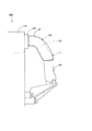
なお、図1はカバー部材1の装着状態を示す概略正面図を示し、図2はカバー部材1の装着状態を示す概略側面図を示す。
An embodiment of the present invention will be described below with reference to the drawings.
Note that FIG. 1 shows a schematic front view showing a mounted state of the cover member 1, and FIG. 2 shows a schematic side view showing a mounted state of the cover member 1.
図3は遮熱シート10の概略斜視図を示し、図4は遮熱シート10の概略分解斜視図を示し、図5は遮熱シート10の平面図を示し、図6は遮熱シート10の断面図による説明図を示す。図7はエキマニ120に装着した状態におけるカバー部材1の概略断面図を示し、図8はエキマニ120に装着した状態におけるカバー部材1説明図を示している。
FIG. 3 shows a schematic perspective view of the
なお、図3において、外層部材20の一部を点線で示して透過状態を表し、外層部材20に組み付けられたコルゲート成形材30の構成を明確にしている。また図4においても同様の箇所を点線で示している。
In addition, in FIG. 3, a part of the
図6及び図8について詳しく説明すると、図6(a)は図5におけるA−A断面図を示し、図6(b)は図5におけるB−B断面図を示し、図6(c)は図5におけるC−C断面図を示し、図6(d)は図5におけるD−D断面図を示しており、図8(a)は図7におけるE−E断面図を示し、図8(b)は図8(a)におけるα部分の拡大図を示している。 6 and 8 will be described in detail. FIG. 6A shows a sectional view taken along the line AA in FIG. 5, FIG. 6B shows a sectional view taken along the line BB in FIG. 5A is a cross-sectional view taken along the line CC, FIG. 6D shows a cross-sectional view taken along the line DD in FIG. 5, FIG. 8A shows a cross-sectional view taken along the line EE in FIG. b) shows an enlarged view of the α part in FIG. 8 (a).
この一実施形態におけるエンジンの排気装置100は、エンジン110から排出された排ガスが導通される排気マニホールド120(エキマニ120)と、エキマニ120の下流側に直結された触媒コンバータ130(いわゆる、エキマニ直下型触媒コンバータ)とで構成されており、エキマニ120に対してカバー部材1が装着されている。
The
なお、エキマニ120に装着されているカバー部材1の具体的形状は、装着対象であるエキマニ120等の形状や設置箇所、周辺の構造によって相違するものの、基本的な構成は同じである。
Although the specific shape of the cover member 1 mounted on the
カバー部材1について図1及び図2に基づいて詳述すると、カバー部材1は、エキマニ120の形状に合わせて成形した2枚の遮熱シート10を、上下方向からエキマニ120を挟み込んで覆うように設置し、2枚の遮熱シート10同士を固定することでエキマニ120に装着されている。
The cover member 1 will be described in detail based on FIGS. 1 and 2. The cover member 1 covers the two
このカバー部材1の上流側端部は、エンジン110と接合するエキマニ120のフランジ121から延びるエキマニ配管122と当接され、カバー部材1の下流側端部は触媒コンバータ130と連結する側のエキマニ配管122と当接されている。
The upstream end of the cover member 1 is in contact with the
このように装着されたカバー部材1は、エンジン110とエキマニ120との接合部分、すなわちフランジ121の直下からエキマニ120と触媒コンバータ130の連結部分までを周方向にわたって囲繞している。
The cover member 1 mounted in this way surrounds the joint portion between the
また、エキマニ120とカバー部材1との間には内部には空気が封入された閉鎖空間Vが形成されており、空気が外部へ略流入出しないように構成されている。
なお、本実施形態において、閉鎖空間Vには空気が封入されているが、空気である必要はなく、安全で安定性の高い気体を封入してもよく、また真空としてもよい。
Further, a closed space V in which air is sealed is formed between the
In the present embodiment, air is sealed in the closed space V, but it does not have to be air, and a safe and highly stable gas may be sealed, or a vacuum may be used.
次に、カバー部材1を形成する遮熱シート10について、図3乃至図6に基づいて説明する。なお、図3乃至図6においては、遮熱シート10の構造を明確にするために、遮熱シート10を平板状に形成されたものとするが、実際は設置個所の形状に合わせて成形する。
遮熱シート10は、図3及び図4に示すように、上部に設けられた外層部材20に対して下方からコルゲート成形材30を組み付けて構成されている。
Next, the
As shown in FIGS. 3 and 4, the
外層部材に対応する外層部材20は、可撓性のあるステンレス鋼製のステンレス箔材で構成された板材であり、天板21と、天板21の各端辺から下方に所定の長さ延ばした側壁22と、側壁22の下端部から外方に突出した突出部23とで構成され、突出部23の下端面には緩衝部材50が備えられている。
The
なお、側壁22の高さ及び突出部23の突出量は、装着部位の形状や周辺構造などに応じて適宜設計される。
また、側壁22は天板21の四方向の端部から下方に延ばしているが、必ずしも四方向全てから下方に延ばす必要はなく、平面方向に直交する第1方向x又は第2方向yの両端部から下方に延ばす構成としてもよい。
The height of the
Further, although the
突出部23に備えられた緩衝部材50は、ガラスウールやロックウールのように断熱材として周知な無機繊維系のものを振動が吸収可能な厚さとなるように織り込んで形成されている。この厚みは、設置する場所や所望の振動吸収の度合、配置箇所の熱伝導率などに応じて適宜設計される。
The cushioning
内層部材に対応するコルゲート成形材30は、304ステンレス鋼製のステンレス箔材に対して、第1方向xと第2方向yに延びる凹凸の波付け加工が施され、第1方向xと第2方向yに延びる凹凸によって構成されるコルゲート形状が形成された成形材である。
The
コルゲート成形材30に形成されたコルゲート形状について詳述すると、第1方向xに沿って形成される凹状の谷部31と凸状の山部32とが第2方向yに沿って交互に配置されるとともに、第1方向xに沿って形成された谷部31及び山部32に、第1方向xに沿って交互に凸状部33と凹状部34とが交互に配置されてコルゲート形状が構成されている(図4乃至図6参照)。
To elaborate on the corrugated shape formed on the
凸状部33は波形の波凸部で形成されており、凹状部34は波形の波凹部で形成されている。この山部32における凸状部33の第2方向yの幅が最も狭く、且つ凹状部34の第2方向yの幅が最も広くなる連続形状で形成されており、また、谷部31における凹状部34の第2方向yの幅が最も狭く、且つ凸状部33の第2方向yの幅が最も広くなる連続形状で形成されている(図6参照)。
The
なお、凸状部33と凹状部34との高さの差は、側壁22の高さと略同一に構成されている。
The difference in height between the
谷部31には谷底面31aが形成され、山部32には山上面32aが形成され、谷底面31aと山上面32aとを連結する連結側面40が形成されている。換言すると、第2方向yの断面において、谷部31は谷底面31aと第2方向y両側に形成された連結側面40とで略角型凹状に形成されており、山部32は山上面32aと第2方向y両側に形成される連結側面40とで略角型逆凹状に形成されている。また、第2方向yの断面において、連結側面40が山上面32aまたは谷底面31aとなす角度は80°〜100°の範囲の略90°で形成されている。
なお、この連結側面40と、山上面32aまたは谷底面31aとがなす角度は必ずしも80〜100度である必要はなく、例えば、山上面32aまたは谷底面31aとがなす角度が鋭角となるように適宜変更してもよい。
A
The angle formed by the connecting
このように構成されたコルゲート成形材30を、天板21と同面積の平面矩形状となるようにして、外層部材20に嵌合させるとともに、コルゲート成形材30の端部と突出部23の内側端部とを溶接して一体化させることにより、遮熱シート10が形成される。
なお、外層部材20とコルゲート成形材30は溶接により一体化させているが、必ずしもこの方法で一体化する必要はなく、例えばボルトなどを用いて固定しても構わない。
The
Although the
この遮熱シート10は、図6に示すように、谷部31の凹状部34が突出部23に設けられた緩衝部材50の底面側と略面一になるとともに、山部32の凸状部33が天板21と当接している。
As shown in FIG. 6, in the
このように構成される遮熱シート10は、上述のように、エキマニ120や触媒コンバータ130などの対象部材の形状に応じて立体形状に成形(プレス加工)されカバー部材1を構成し、エキマニ120や触媒コンバータ130に組み付けることができる。
なお、成型された外層部材20とコルゲート成形材30とを組み合わせて遮熱シート10を形成してもよいし、遮熱シート10を変形加工してもよい。
As described above, the
The
以下、プレス加工したカバー部材1をエキマニ120に組み付けた状態について、図7及び図8に基づいて説明する。
ここで、図7及び図8では、説明を簡略化するために、エキマニ120を円環状の管体とし、エキマニ120の内部を導通する排ガスの流れる方向を導通方向Dとする。また、遮熱シート10の第2方向yを導通方向Dと一致させるとともに、図8中の横方向が第1方向xとする。
Hereinafter, a state in which the press-processed cover member 1 is assembled to the
Here, in FIGS. 7 and 8, for simplification of the description, the
まず、カバー部材1の製造方法について簡単に説明する。
適当な大きさのコルゲート成形材30を2枚用意し、コルゲート成形材30において隣接する凹状部34の頂点に沿う面がエキマニ配管122の外径と同一になるように屈曲させて半円状にプレス加工して成形する。
First, a method of manufacturing the cover member 1 will be briefly described.
Two
同様に、コルゲート成形材30よりも一回り大きな外層部材20を2枚用意し、天板21がコルゲート成形材30の凸状部33の頂点沿う面が形成する半円の外径と同一となるように外層部材20を屈曲させて半円状にプレス加工して成形する。
なお、この場合の外層部材20は、天板21の第2方向yの両端部のみに側壁22が設けられているものとする。
Similarly, two
In this case, it is assumed that the
このようにプレス加工された外層部材20に対してコルゲート成形材30を下方から嵌め込んで、溶接するとともに、を断面視半円状の遮熱シート10を形成する。第1方向xにおいて両端側に余った天板21(以下、天板端部21aとする)を、円弧の径外方向に向けて突出するように成形する。
The
そして、それぞれ成形された遮熱シート10を上下方向からエキマニ配管122を挟み込むようして設置して(図8参照)、上方の遮熱シート10に設けられた天板端部21a(天板端部21au)で、下方の遮熱シート10に設けられた天板端部21a(天板端部21ad)をくるむように折り返して、上下方向から天板端部21a同士をかしめることで遮熱シート10同士を固定するとともに、エキマニ配管122に対して固定する。この状態において遮熱シート10における第2方向yは、導通方向Dに沿っている。
Then, each of the molded
なお、本実施形態では、説明を簡易にするために遮熱シート10の第2方向yと導通方向Dを一致させるとともに、図8中の横方向が第1方向xとなるように遮熱シート10を配置して成形しているが、例えば、導通方向Dと第1方向xと一致するように遮熱シート10を配置してもよいし、また、導通方向Dが第1方向xと交差する方向に沿うように遮熱シート10を配置してもよい。換言すると、成形加工された遮熱シート10はコルゲート成形材30の凹状部34及び凸状部33が特定の方向に沿うよう成形されたものである必要はない。
In the present embodiment, for the sake of simplicity, the second direction y of the
また、本実施形態では、一方の外層部材20の一部分(天板端部21au)が他方の外層部材20の一部分(天板端部21ad)をくるむように折り返してかしめることで遮熱シート10同士を固定する構成としているが、遮熱シート10同士を固定する方法はこの構成に限定されず、例えば外層部材20同士をボルトやクリップで固定し、又は外層部材20同士を溶接することで固定してもよい。
Further, in the present embodiment, the
このようにエキマニ配管122に組み付けられたカバー部材1は、遮熱シート10の端部に備えられた緩衝部材50がエキマニ配管122の上流側(フランジ121の直下部位)及びエキマニ配管122の下流側(触媒コンバータ130の近辺)と当接しており、外層部材20とエキマニ配管122との間には、内部に空気が流入出することが妨げられた閉鎖空間Vが形成されている。
In the cover member 1 assembled to the
また、上述のようにコルゲート成形材30を構成する凸状部33が天板21と当接しているとともに、コルゲート成形材30を構成する凹状部34がエキマニ配管122と当接するため、閉鎖空間Vは外層部材20とコルゲート成形材30とで形成される複数の第一閉鎖空間V1と、コルゲート成形材30とエキマニ配管122とで形成される複数の第二閉鎖空間V2とに区分けされている。
Further, as described above, the
この複数の第一閉鎖空間V1及び第二閉鎖空間V2は、それぞれが他の第一閉鎖空間V1及び第二閉鎖空間V2など独立した閉じられた閉鎖空間を形成しているため、互いに空気の流入出が抑制されている。このため、閉鎖空間V内での空気の対流を防止できる。 Since the plurality of first closed spaces V1 and the second closed space V2 form independent closed closed spaces such as the other first closed space V1 and the second closed space V2, air flows into each other. The output is suppressed. Therefore, convection of air in the closed space V can be prevented.
また、第一閉鎖空間V1及び第二閉鎖空間V2が複数形成されているため、例えば、第一閉鎖空間V1の一部分が破損しても、他の第一閉鎖空間V1は閉鎖された空間を維持することができるため、意図せずに損傷した場合であっても、エキマニ配管122の放熱を妨げることができる。
Further, since a plurality of the first closed space V1 and the second closed space V2 are formed, for example, even if a part of the first closed space V1 is damaged, the other first closed space V1 maintains the closed space. Therefore, even if the space is unintentionally damaged, the heat dissipation of the
このように構成されたカバー部材1は、エンジン110から排出された排ガスを導通し、放熱するエキマニ配管122の外周を囲繞するように固定される外層部材20と、外層部材20とエキマニ配管122との間に設けられるコルゲート成形材30とで構成され、外層部材20とコルゲート成形材30の間、及び、エキマニ配管122とコルゲート成形材30との間には、それぞれ閉じられた第一閉鎖空間V1及び第二閉鎖空間V2が形成されるため、断熱材を用いることなくエキマニ配管122から放熱されることを遮ることができる。
The cover member 1 configured in this way includes an
詳述すると、エキマニ配管122に固定されたカバー部材1は、下方に配置された遮熱シート10の天板端部21adを、上方に配置した遮熱シート10の天板端部21auでくるむように折り返してかしめることで、コルゲート成形材30とエキマニ配管122、及び外層部材20とコルゲート成形材30との間にそれぞれ閉じられた第一閉鎖空間V1及び第二閉鎖空間V2が形成される。このため、第一閉鎖空間V1及び第二閉鎖空間V2に封入した空気が21a同士の間から、カバー部材1の外部に排出されることを防止できる。
More specifically, the cover member 1 fixed to the
また、閉鎖空間Vを第一閉鎖空間V1と第二閉鎖空間V2とで区分けすることにより、カバー部材1の熱抵抗を向上させることができるため、エキマニ配管122から外層部材20へ伝わる単位時間あたりの熱量を減少させることができる。すなわち、エキマニ配管122から外部に放出される単位時間当たりの熱量を減少させることができる。したがって、エキマニ配管122の内部に蓄積された熱を保持することができ、高温を保持した排ガスを触媒コンバータ130に送ることができる。
Further, by dividing the closed space V into the first closed space V1 and the second closed space V2, the thermal resistance of the cover member 1 can be improved, so that per unit time transmitted from the
このように、カバー部材1に空気層である第一閉鎖空間V1及び第二閉鎖空間V2を形成することで熱抵抗を向上させることができ、エキマニ配管122から外部に放出される熱量を減少させることができる。したがって、カバー部材1の内部に断熱材を用いることなく、エンジン110から排気された排ガスの熱がエキマニ配管122から放熱されることを遮ることができる。これにより、エキマニ配管122の下流側にある触媒コンバータ130などに高温を保持した排ガスを送ることができ、効率よく排ガスに含まれる有害物質を無害物質に変化させることができる。
In this way, by forming the first closed space V1 and the second closed space V2, which are air layers, in the cover member 1, the thermal resistance can be improved, and the amount of heat released to the outside from the
また近年、燃費を向上させるために理想空燃比よりもガソリンの濃度を薄くした希薄空燃比でガソリンを燃焼(希薄燃焼)させることがあるが、この希薄燃焼は、理論空燃比で燃焼するストイキオメトリ燃焼に比べて有毒ガスである窒素酸化物(NOx)などが発生しやすい。そのため、触媒コンバータ130に備えた触媒が十分に活性する温度となったときに、有毒ガスの排出を極力低減できるストイキオメトリ燃焼から希薄燃焼に切り替えている。
In recent years, in order to improve fuel efficiency, gasoline may be burned (lean burn) at a lean air-fuel ratio in which the concentration of gasoline is lower than the ideal air-fuel ratio. Nitrogen oxides (NOx), which are toxic gases, are more likely to be generated than metric combustion. Therefore, when the temperature at which the catalyst provided in the
本実施形態では、カバー部材1でエキマニ配管122を囲繞することにより、エキマニ配管122からの放熱を遮れるため、エキマニ配管122を流れる排ガスを高温で保持できる。これにより、高温に保持された排ガスを触媒コンバータ130に送ることができ、効率よく触媒の温度を上昇させることができる。したがって、早期にストイキオメトリ燃焼から希薄空燃比に移行して、燃費を向上させることができる。
In the present embodiment, by surrounding the
また、例えば外層部材20が意図せずに損傷した場合であっても、コルゲート成形材30がエキマニ配管122からの放熱を遮ることができるため、触媒コンバータ130などに高温を保持した排ガスを送りことができ、有害物質を排出することを防止できる。
Further, for example, even if the
さらにまた、カバー部材1をエキマニ配管122に固定させた場合には、エンジン110の振動による影響を減少でき、振動に起因するカバー部材1の脱落及び損傷を防止できる。したがって、触媒コンバータ130などに高温を保持した排ガスを確実に送ることができ、触媒の活性効率を向上させることができ、有害物質を排出することを防止できる。
Furthermore, when the cover member 1 is fixed to the
また、外層部材20が、エキマニ配管122の全周を囲繞することにより、エキマニ配管122から外部へ放熱する部位を減少させることができるため、エキマニ配管122からの熱の放出量を減少させることができる。これにより、排ガスの温度を高温に保つことができ、触媒コンバータ130などに備えた触媒の活性効率を向上させることができる。
Further, since the
さらにまた、外層部材20とエキマニ配管122とが、振動を吸収可能な緩衝部材50を介して当接されていることにより、エンジン110の稼働に起因する振動などを緩衝部材50で緩衝して、外層部材20がエキマニ配管122から脱落することや外層部材20やコルゲート成形材30が振動により損傷することを防止できる。
Furthermore, since the
加えて、エキマニ配管122及び外層部材20と接触しているコルゲート成形材30は第1方向xと第2方向yに延びる凹凸の波付け加工が施されているため、凹凸方向に対する弾性を有しており、エンジン110の振動を吸収できるとともに、音の原因となる空気振動も吸収することができるため、遮音効果も有する。
In addition, the
さらにまた、緩衝部材50が断熱性を有しているため、エキマニ配管122から外層部材20への熱伝導の効率を減少させることができ、エキマニ配管122を導通する排ガスから放出される熱が外層部材20へ熱伝導することを遮ることができる。したがって、エキマニ配管122の下流側に配置された触媒コンバータ130に高温を保持した排ガスを送ることができ、触媒コンバータ130などに備えた触媒の活性効率を向上させることができる。
Furthermore, since the cushioning
なお、本実施形態のように、外層部材20aを重ね合わせて固定させてカバー部材1を形成する場合、外層部材20aの接触部分に緩衝部材50を取付けて固定してもよいし、緩衝部材50を外して固定しでもよい。緩衝部材50を取付けて2枚の遮熱シート10をボルト固定する場合、緩衝部材50同士を重ね合すこととなるため、一方の遮熱シート10から他方の遮熱シート10への熱の伝導をより妨げることができる。
When the cover member 1 is formed by overlapping and fixing the outer layer members 20a as in the present embodiment, the cushioning
さらにまた、コルゲート成形材30が、凹凸形状が形成された金属板(304ステンレス鋼製のステンレス箔材)で構成されることにより、コルゲート成形材30の変形性を向上させることができる。このためエキマニ配管122などの形状に合わせてカバー部材1を成形加工(プレス加工)した場合に、第一閉鎖空間V1や第二閉鎖空間V2を閉じられた空間として維持しながら変形させることができる。
Furthermore, since the
また、コルゲート成形材30を凹凸形状とすることで、第一閉鎖空間V1及び第二閉鎖空間V2に区分けすることができるため、第一閉鎖空間V1及び第二閉鎖空間V2の内部での空気の導通性を低減することができる。したがって、カバー部材1を構成する外層部材20やコルゲート成形材30が損傷した場合であっても、内部に封入した空気が漏れ出ることを防止できるため、エキマニ配管122から放熱する熱量を減少させることができる。
Further, since the
さらにまた、凹凸形状の凸部が外層部材20と接触している場合には、コルゲート成形材30で外層部材20を支持することができるため、カバー部材1の強度及び剛性を向上させることができる。
Furthermore, when the convex portion having a concave-convex shape is in contact with the
このような構成を有するカバー部材1を用いて、熱源である発熱体の温度に対する外層部材20及びエキマニ配管122の表面温度を、外層部材20とエキマニ配管122との間に断熱部材を挟み込んだ遮熱ヒートプロテクタと比較して確認したところ、外層部材20及びエキマニ配管122の温度はともに差がなかった。また、エキマニ配管122の立ち上がり時間も共に差がなかったことが確認できた。
このことから、カバー部材1は従来のような断熱部材を用いた遮熱ヒートプロテクタと性能としては差異がない。
Using the cover member 1 having such a configuration, the surface temperature of the
From this, the cover member 1 has no difference in performance from the conventional heat shield heat protector using the heat insulating member.
この発明の構成と、上述の実施形態との対応において、
この発明の熱源は、エキマニ配管122に対応し、以下同様に、
カバー部材は、カバー部材1に対応し、
外層部材は、外層部材20に対応し、
内層部材は、コルゲート成形材30に対応するが、
この発明は、上述の実施形態の構成のみに限定されるものではなく、多くの実施の形態を得ることができる。
In the correspondence between the configuration of the present invention and the above-described embodiment,
The heat source of the present invention corresponds to the
The cover member corresponds to the cover member 1 and
The outer layer member corresponds to the
The inner layer member corresponds to the
The present invention is not limited to the configuration of the above-described embodiment, and many embodiments can be obtained.
例えば、本実施形態では、カバー部材1はエキマニ配管122のみを囲繞する構成としたが、この構成に限らず、例えば、エキマニ配管122の一部を覆う構成や、エンジン110の全部又は一部を含めたエキマニ配管122の全部又は一部を覆うあるいは囲繞する構成であってもよい。
For example, in the present embodiment, the cover member 1 is configured to surround only the
さらには、エキマニ配管122のみならず、エキマニ配管122の下流側に配置された触媒コンバータ130の一部又は全部も囲繞する構成や、触媒コンバータ130の下流側に配置された床下コンバータやマフラーなどを囲繞してもよいし、これらの触媒コンバータを繋ぐ配管など囲繞するとしてもよい。
Further, not only the
さらに言えば、本実施形態においてカバー部材1は高温を生じる放熱体を囲繞しているが、例えば冷却用ガスなどを通す配管や、冷却装置を囲繞し、配管などの内部への吸熱を防止するのにも使用することができる。 Furthermore, in the present embodiment, the cover member 1 surrounds a heat radiating body that generates a high temperature, but for example, it surrounds a pipe through which a cooling gas or the like is passed or a cooling device to prevent heat absorption into the pipe or the like. Can also be used for.
すなわち、カバー部材1で覆う部位は、覆う箇所からの放熱や吸熱を防止したい箇所であれば、どのような場所であっても構わず、その保温目的も触媒の活性させることに限定されず、例えば配管などを導通する熱媒体の放熱や吸熱による熱媒体の温度変化を抑えて他の場所に熱媒体を移動させることを目的としてもよい。 That is, the portion covered by the cover member 1 may be any location as long as it is desired to prevent heat dissipation and heat absorption from the covered portion, and the purpose of heat retention is not limited to the activation of the catalyst. For example, the purpose may be to move the heat medium to another place by suppressing the temperature change of the heat medium due to heat dissipation or heat absorption of the heat medium conducting the pipe or the like.
また例えば、外層部材20は、緩衝部材50を介してエキマニ配管122に当接されているが、例えばエキマニ配管122に対して、直接的当接させてもよい。
またコルゲート成形材30は、閉鎖空間Vを2以上の閉じられた空間に区分けする構成であればどのような構成でもよく、例えば、外層部材20とエキマニ配管122との間に形成される閉鎖空間Vを区分けするようにエキマニ配管122と当接した外層部材20に組み付けられた構成や、第一閉鎖空間V1を形成するようにエキマニ配管122と当接した一または複数の筐体で構成された場合を含む。
また、コルゲート成形材30の代わりに所定の間隔を隔てたフラットな板材を用いてもよい。
Further, for example, the
Further, the
Further, instead of the
また、外層部材20やコルゲート成形材30をステンレス鋼製のステンレス箔材で構成しているが、ステンレス鋼製である必要はなく、高温耐性のある金属であればどのような金属でもよく、例えば鉄製などであってもよい。
Further, although the
1 遮熱ヒートプロテクタ
20 アルミ板
30 コルゲート成形材
50 緩衝部材
122 エキマニ配管
V 閉鎖空間
1 Heat
Claims (4)
前記外層部材と前記熱源との間に設けられる内層部材とで構成され、
前記外層部材は、天板と、該天板の各端辺から下方に所定の長さ延ばした側壁とが備えられ、
前記内層部材は、凸状部と凹状部とが交互に配置された凹凸形状で形成された金属板で構成され、
前記凸状部と前記凹状部との高さの差は、前記側壁の高さと略同一に構成され、
前記内層部材は、前記外層部材に嵌合して、一体化されるとともに、前記凸状部が前記天板と当接し、
前記外層部材と前記内層部材の間に閉じられた内側閉鎖空間を形成し、
前記熱源に装着した状態で、前記凹状部が前記熱源と当接し、前記熱源と前記内層部材との間に、前記内側閉鎖空間と独立して閉じられた外側閉鎖空間が形成されるように構成された
カバー部材。 An outer layer member that is fixed so as to cover the outer circumference of the heat source,
It is composed of an inner layer member provided between the outer layer member and the heat source.
The outer layer member includes a top plate and a side wall extending downward from each end side of the top plate by a predetermined length.
The inner layer member is composed of a metal plate formed in a concavo-convex shape in which convex portions and concave portions are alternately arranged.
The difference in height between the convex portion and the concave portion is configured to be substantially the same as the height of the side wall.
The inner layer member is fitted and integrated with the outer layer member, and the convex portion comes into contact with the top plate.
A closed inner closed space is formed between the outer layer member and the inner layer member.
While wearing the heat source, the concave portion is the heat source in contact, between the inner member and the heat source, so a closed Ji was outside the closed space independently of said inner closed space is formed The constructed cover member.
前記熱源の全周を囲繞する構成とした
請求項1に記載のカバー部材。 The outer layer member is
The cover member according to claim 1, which is configured to surround the entire circumference of the heat source.
請求項1又は請求項2に記載のカバー部材。 The outer layer member and the heat source is a cover member according to claim 1 or claim 2 which is against through capable of absorbing cushioning member vibration.
請求項3に記載のカバー部材。 The cover member according to claim 3, wherein the cushioning member has heat insulating properties.
Priority Applications (1)
| Application Number | Priority Date | Filing Date | Title |
|---|---|---|---|
| JP2017074892A JP6879548B2 (en) | 2017-04-05 | 2017-04-05 | Cover member |
Applications Claiming Priority (1)
| Application Number | Priority Date | Filing Date | Title |
|---|---|---|---|
| JP2017074892A JP6879548B2 (en) | 2017-04-05 | 2017-04-05 | Cover member |
Publications (2)
| Publication Number | Publication Date |
|---|---|
| JP2018178765A JP2018178765A (en) | 2018-11-15 |
| JP6879548B2 true JP6879548B2 (en) | 2021-06-02 |
Family
ID=64281401
Family Applications (1)
| Application Number | Title | Priority Date | Filing Date |
|---|---|---|---|
| JP2017074892A Active JP6879548B2 (en) | 2017-04-05 | 2017-04-05 | Cover member |
Country Status (1)
| Country | Link |
|---|---|
| JP (1) | JP6879548B2 (en) |
Family Cites Families (2)
| Publication number | Priority date | Publication date | Assignee | Title |
|---|---|---|---|---|
| JPS58158114U (en) * | 1982-04-19 | 1983-10-21 | マツダ株式会社 | Multiple exhaust pipe structure |
| JP2002349259A (en) * | 2001-05-24 | 2002-12-04 | Isuzu Motors Ltd | Heat retaining structure for exhaust gas processing device and exhaust passage |
-
2017
- 2017-04-05 JP JP2017074892A patent/JP6879548B2/en active Active
Also Published As
| Publication number | Publication date |
|---|---|
| JP2018178765A (en) | 2018-11-15 |
Similar Documents
| Publication | Publication Date | Title |
|---|---|---|
| JP2005083376A (en) | Muffler having internal heat shield | |
| JP6204398B2 (en) | Turbine housing | |
| JP2008240589A (en) | Engine exhaust structure | |
| KR101722957B1 (en) | Adiabatic joint structure of exhaust pipe | |
| JP6879548B2 (en) | Cover member | |
| JP2013227984A (en) | Structural component, in particular, shielding component of heat shield member form | |
| JP2007100689A (en) | Catalytic converter cover | |
| JP5363542B2 (en) | Support device for exhaust parts | |
| AU2016201400B2 (en) | Heat insulator | |
| CN100425807C (en) | Zigzag type catalytic converter | |
| JP2017072074A (en) | Exhaust emission control device | |
| KR20160141150A (en) | Insulation for exhaust system with advanced performance in assembly and sound absorption | |
| KR101550020B1 (en) | Heat protector | |
| KR101552338B1 (en) | Multilayered sheet, Heat protector using the same and Manufacturing method of the same | |
| JP7404592B2 (en) | Diesel engine exhaust treatment equipment and diesel engines | |
| KR101362066B1 (en) | Structure of tail-pipe for vehicle | |
| JP2023148784A (en) | Exhaust emission control device | |
| EP1911943B1 (en) | Exhaust gas cooling device | |
| JP5145199B2 (en) | Cover for exhaust parts | |
| JP4984084B2 (en) | Silencer | |
| TWI769236B (en) | Catalyst carrier and exhaust purification device | |
| JP2005220821A (en) | Exhaust pipe | |
| KR101134384B1 (en) | Car silencer | |
| JP2005120854A (en) | Thermal insulation plate fitting structure of exhaust pipe | |
| JP2006207638A (en) | Cylindrical member structure |
Legal Events
| Date | Code | Title | Description |
|---|---|---|---|
| A621 | Written request for application examination |
Free format text: JAPANESE INTERMEDIATE CODE: A621 Effective date: 20200123 |
|
| A977 | Report on retrieval |
Free format text: JAPANESE INTERMEDIATE CODE: A971007 Effective date: 20201222 |
|
| A131 | Notification of reasons for refusal |
Free format text: JAPANESE INTERMEDIATE CODE: A131 Effective date: 20210105 |
|
| A521 | Request for written amendment filed |
Free format text: JAPANESE INTERMEDIATE CODE: A523 Effective date: 20210304 |
|
| TRDD | Decision of grant or rejection written | ||
| A01 | Written decision to grant a patent or to grant a registration (utility model) |
Free format text: JAPANESE INTERMEDIATE CODE: A01 Effective date: 20210406 |
|
| A61 | First payment of annual fees (during grant procedure) |
Free format text: JAPANESE INTERMEDIATE CODE: A61 Effective date: 20210422 |
|
| R150 | Certificate of patent or registration of utility model |
Ref document number: 6879548 Country of ref document: JP Free format text: JAPANESE INTERMEDIATE CODE: R150 |
|
| R250 | Receipt of annual fees |
Free format text: JAPANESE INTERMEDIATE CODE: R250 |