JP6872995B2 - Radioactivity analyzer - Google Patents
Radioactivity analyzer Download PDFInfo
- Publication number
- JP6872995B2 JP6872995B2 JP2017130359A JP2017130359A JP6872995B2 JP 6872995 B2 JP6872995 B2 JP 6872995B2 JP 2017130359 A JP2017130359 A JP 2017130359A JP 2017130359 A JP2017130359 A JP 2017130359A JP 6872995 B2 JP6872995 B2 JP 6872995B2
- Authority
- JP
- Japan
- Prior art keywords
- unit
- radioactivity
- container
- intensity
- radiation
- Prior art date
- Legal status (The legal status is an assumption and is not a legal conclusion. Google has not performed a legal analysis and makes no representation as to the accuracy of the status listed.)
- Expired - Fee Related
Links
- 238000001514 detection method Methods 0.000 claims description 95
- 230000005855 radiation Effects 0.000 claims description 83
- 238000007493 shaping process Methods 0.000 claims description 64
- 238000004364 calculation method Methods 0.000 claims description 30
- 239000000835 fiber Substances 0.000 claims description 29
- 238000003860 storage Methods 0.000 claims description 25
- 230000008859 change Effects 0.000 claims description 12
- 239000000284 extract Substances 0.000 claims description 5
- 238000004458 analytical method Methods 0.000 description 32
- 238000005259 measurement Methods 0.000 description 28
- 238000009826 distribution Methods 0.000 description 21
- 238000000034 method Methods 0.000 description 16
- 238000005316 response function Methods 0.000 description 16
- 230000002093 peripheral effect Effects 0.000 description 10
- 238000001228 spectrum Methods 0.000 description 10
- 230000002238 attenuated effect Effects 0.000 description 6
- 238000010586 diagram Methods 0.000 description 6
- 238000002474 experimental method Methods 0.000 description 5
- 230000008569 process Effects 0.000 description 4
- TVFDJXOCXUVLDH-RNFDNDRNSA-N cesium-137 Chemical compound [137Cs] TVFDJXOCXUVLDH-RNFDNDRNSA-N 0.000 description 3
- 230000001902 propagating effect Effects 0.000 description 3
- 230000000694 effects Effects 0.000 description 2
- 230000003993 interaction Effects 0.000 description 2
- 230000002285 radioactive effect Effects 0.000 description 2
- 239000000941 radioactive substance Substances 0.000 description 2
- 238000004088 simulation Methods 0.000 description 2
- RYGMFSIKBFXOCR-UHFFFAOYSA-N Copper Chemical compound [Cu] RYGMFSIKBFXOCR-UHFFFAOYSA-N 0.000 description 1
- 230000005540 biological transmission Effects 0.000 description 1
- 229910052802 copper Inorganic materials 0.000 description 1
- 239000010949 copper Substances 0.000 description 1
- 230000010354 integration Effects 0.000 description 1
- 238000004519 manufacturing process Methods 0.000 description 1
- 239000000463 material Substances 0.000 description 1
- 239000012857 radioactive material Substances 0.000 description 1
- 230000004044 response Effects 0.000 description 1
- 230000035945 sensitivity Effects 0.000 description 1
- 230000009466 transformation Effects 0.000 description 1
Images


Landscapes
- Measurement Of Radiation (AREA)
Description
本発明は、測定対象物の放射能の強度を測定する放射能分析装置に関する。 The present invention relates to a radioactivity analyzer that measures the intensity of radioactivity of an object to be measured.
従来技術として、放射線核種毎に放射線検出器の応答関数を算出する応答関数算出手段を有し、逆問題演算の一種であるアンフォールディングによって信号復元演算を行う放射能分析装置が開示されている(たとえば特許文献1参照)。 As a prior art, a radioactivity analyzer that has a response function calculating means for calculating the response function of a radiation detector for each radiation nuclide and performs a signal restoration calculation by unfolding, which is a kind of inverse problem calculation, is disclosed ( For example, see Patent Document 1).
たとえば特許文献1に開示される技術では、測定対象試料は鉛などで形成された容器内に配置される。これによって、容器外からの放射線が容器によって遮蔽された状態での放射線量の測定を目的としている。しかし、容器外からの放射線を完全に遮蔽できない場合があり、周辺環境の放射線量が多い場所では試料の放射能強度を高い精度で測定できないという問題点がある。
For example, in the technique disclosed in
本発明の目的は、周辺環境の放射線量の多少に関わらず試料の放射能強度を高い精度で測定できる、汎用性の高い放射能分析装置を提供することである。 An object of the present invention is to provide a highly versatile radioactivity analyzer capable of measuring the radioactivity intensity of a sample with high accuracy regardless of the amount of radiation in the surrounding environment.
本願に開示される放射能分析装置は、
放射能強度の測定対象となる試料を収容する容器と、
前記容器の内方における放射線を検出し、内方放射能強度として出力する内方測定部と、
前記容器の外方における放射線を検出し、外方放射能強度として出力する外方測定部と、
前記容器の外方における放射線量を第1変数とし、該第1変数を変化させたときの前記内方放射能強度の変化を表す第1関数を含む第1式と、前記容器の内方における放射線量を第2変数とし、該第2変数を変化させたときの前記外方放射能強度の変化を表す第2関数を含む第2式と、を記憶する補正関数記憶部と、
前記内方測定部による測定値である前記内方放射能強度と、前記外方測定部による測定値である前記外方放射能強度と、を用いて前記補正関数記憶部に記憶される前記第1関数を含む前記第1式と前記第2関数を含む前記第2式との連立方程式を解き、前記第1式および前記第2式に含まれる前記第2変数xの値を導出することにより、前記容器内の前記試料の放射能強度を演算する補正演算部とを備える。
The radioactivity analyzer disclosed in the present application is
A container that houses the sample for which the radioactivity intensity is to be measured, and
An inner measuring unit that detects radiation inside the container and outputs it as the inner radioactivity intensity.
An external measuring unit that detects radiation on the outside of the container and outputs it as the external radioactivity intensity.
A first variable radiation dose at the outside of said container, a first expression including a first function representing a change in the inner radiation intensity when varying the first variable, inwardly before Symbol vessel A correction function storage unit that stores a second equation including a second function that represents a change in the outer radioactivity intensity when the second variable is changed, and a correction function storage unit that stores the radiation amount in
The first, which is stored in the correction function storage unit using the inner radioactivity intensity, which is a value measured by the inner measuring unit, and the outer radioactivity intensity, which is a value measured by the outer measuring unit. By solving the simultaneous equations of the first equation including one function and the second equation including the second function , and deriving the value of the second variable x included in the first equation and the second equation. , and a correction calculator for calculating the radioactivity intensity of the sample in the container.
本発明によれば、周辺環境の放射線量の多少に関わらず試料の放射能強度を高い精度で測定できる、汎用性の高い放射能分析装置を提供できる。 According to the present invention, it is possible to provide a highly versatile radioactivity analyzer capable of measuring the radioactivity intensity of a sample with high accuracy regardless of the amount of radiation in the surrounding environment.
以下、図面を参照しながら本発明の実施の形態を、複数の形態について説明する。以下の説明においては、各形態に先行する形態ですでに説明している事項に対応している部分には同一の参照符を付し、重複する説明を略す場合がある。構成の一部のみを説明している場合、構成の他の部分は、先行して説明している形態と同様とする。 Hereinafter, a plurality of embodiments of the present invention will be described with reference to the drawings. In the following description, the same reference numerals may be added to the parts corresponding to the matters already described in the forms preceding each form, and duplicate explanations may be omitted. When only a part of the configuration is described, the other parts of the configuration are the same as those described above.
実施の形態1.
図1は、本発明の実施の形態1に係る放射能分析装置1の構成を表す図である。放射能分析装置1は、容器2と、内方測定部3と、外方測定部4と、補正関数記憶部5と、補正演算部6と、表示部27とを備える。容器2は、放射能強度の測定対象となる試料11を収容する。容器2は、たとえば鉛など高い放射線遮蔽能力を有する材料によって形成される。内方測定部3は、容器2の内方における放射線を検出し、検出した結果に基づいて放射能強度を算出し、内方放射能強度として出力する。外方測定部4は、容器2の外方における放射線を検出し、検出した結果に基づいて放射能強度を算出し、外方放射能強度として出力する。
FIG. 1 is a diagram showing the configuration of the
具体的に内方測定部3は、内方検出部12と内方算出部13とを有する。内方検出部12は、容器2の内方に設けられ、容器2の内方の放射線を検出し、検出した結果を内方検出結果として出力する。内方算出部13は、内方検出部12による内方検出結果に基づいて放射能強度を算出し、内方放射能強度として出力する。外方測定部4は、外方検出部14と外方算出部15とを有する。外方検出部14は、容器2の外方に設けられ、容器2の外方における放射線を検出し、検出した結果を外方検出結果として出力する。
Specifically, the
次に、内方算出部13の構成について説明する。内方算出部13は、波形整形部16と、波高分析部21と、信号復元部22と、応答関数記憶部23とを有する。波形整形部16は、内方検出結果に対して波形整形を行う。波形整形とは、ノイズの増加を抑制しながらパルス信号を増幅することである。波形整形では、必要に応じてパルス信号の幅を調整することもある。波形整形部16は、微分回路および積分回路で構成される。
Next, the configuration of the
波高分析部21は、波形整形後のパルス信号のうち、ピーク値が予め定める所定値以上のパルス信号について、そのピーク値をデジタル変換する。またデジタル変換したピーク値に相当するチャンネル(エネルギ)に対して1カウントを加算する。この作業を複数のパルス信号に対して行うことによって、複数のパルス信号について1つの波高分析結果を得る。このようにして得られた波高分析結果は、信号復元部22によって分析される。
The wave
信号復元部22は、応答関数記憶部23に記憶される応答関数を用いて、波高分析結果を分析し、アンフォールディングなどの信号復元演算を行う。これによって信号復元部22は、内方検出部12の内方検出結果に基づいて内方放射能強度を出力する。応答関数は、内方検出部12と内方検出部12に入射する放射線との相互作用を表し、内方検出部12に対する試料11の配置関係、試料11の種類、内方検出部12の種類および内方検出部12の形状に依存する。信号復元演算については、放射能強度Rおよび放射能分布Sの説明において、後述する。
The
次に、外方測定部4の構成について説明する。外方測定部4は、外方検出部14と外方算出部15とを有し、外方算出部15は、補正用波形整形部24と、補正用波高分析部25と、補正用信号復元部26と、補正用応答関数記憶部31とを有する。補正用波形整形部24、補正用波高分析部25、補正用信号復元部26、および補正用応答関数記憶部31は、前述した波形整形部16、波高分析部21、信号復元部22、および応答関数記憶部23と同様の構成および機能を有する。
Next, the configuration of the
次に、補正関数記憶部5および補正演算部6について説明する。補正関数記憶部5は、第1関数g(u)および第2関数f(x)を記憶する。第1関数g(u)は、容器2の外方における放射線量を変化させたときの内方放射能強度の変化を表す。第2関数f(x)は、容器2の内方の放射線量を変化させたときの外方放射能強度の変化を表す。補正演算部6は、内方測定部3による内方放射能強度、外方測定部4による外方放射能強度、ならびに補正関数記憶部5に記憶される第1関数g(u)および第2関数f(x)に基づいて、容器2内の試料11の放射能強度を演算する。また補正演算部6は、内方測定部3による内方放射能強度、外方測定部4による外方放射能強度、ならびに第1関数g(u)および第2関数f(x)に基づいて、周辺環境の放射能強度を演算する。
Next, the correction function storage unit 5 and the
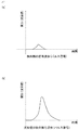
上記のように構成された放射能分析装置1の内方測定部3を用いた、容器2の内方の放射能強度の測定について説明する。まず、内方検出部12が容器2の内方の放射線を検出する。その結果、たとえば図2(a)に示すような内方検出結果が出力される。図2(a)は、時間軸に対する電圧(波高値)で表されるパルス信号である。次に、波形整形部16によって波形整形を行う。波形整形の結果は、たとえば図2(b)に示すような信号である。図2(b)に示すように、波形整形後の信号もパルス信号であり、時間軸に対する電圧(波高値)で表される。この波高整形は、パルス信号を、波形整形の次に行われる波高分析部21による波高分析に適した波形とすることを目的に行われるものである。波高分析部21を成す回路構成が異なれば、波高分析に適したパルスレベルおよびパルス幅が異なるので、波形整形部16は、波高分析部21における波形分析に最適な波形となるように、波形整形を行う。
The measurement of the radioactivity intensity inside the
次に、波高分析部21が、複数の波形整形後のパルス信号を分析する。その結果、たとえば図3(a)に示すような波高分析結果、すなわち波高分布Mが出力される。図3(a)は、各エネルギ値(横軸)に対する計数値(縦軸)で表される。図3(a)に示す波高分析後のスペクトルには、放射性核種に応じたピークが観測される。次に、信号復元部22によってアンフォールディングなどの信号復元演算を行う。信号復元演算の結果は、たとえば図3(b)に示すようなスペクトルである。図3(b)に示すように、信号復元の結果は、各エネルギ値(横軸)に対する計数値(縦軸)で表される。図3(b)に示すように、アンフォールディング後のスペクトルには、放射性核種に応じたピークが観測される。このスペクトルは、放射能分布Sを表す。前述したように、信号復元部22が波高分析結果をアンフォールディングするときには、信号復元部22は波高分析部21からの出力に加えて、応答関数記憶部23に記憶される応答関数を参照する。これによって信号復元部22は、波高分布Mから放射能分布Sを求める。以下、これについて詳細に説明する。
Next, the wave
図3(a)に示す波高分析結果から、放射能分布Sを求める方法について、放射性セシウム137(Cs−137)を例に説明する。図3(a)と同様の波高分析結果を、既知の放射性核種であるCs−137の測定において求めると、図4に示す波高分析結果、すなわち波高分布Mが得られる。放射線は、固有のエネルギを持っており、Cs−137は崩壊の過程で662keVのγ線を放出するので、波高分析結果には662keVのピークが現れる。 A method for obtaining the radioactivity distribution S from the wave height analysis result shown in FIG. 3A will be described by taking radioactive cesium-137 (Cs-137) as an example. When the same wave height analysis result as in FIG. 3A is obtained in the measurement of the known radionuclide Cs-137, the wave height analysis result shown in FIG. 4, that is, the wave height distribution M is obtained. Radiation has an inherent energy, and Cs-137 emits 662 keV γ-rays in the process of decay, so a peak of 662 keV appears in the wave height analysis result.
図4に示すように、たとえばCs−137から放出されたγガンマ線を測定した場合に662keVに観測されるピークは、広がりを有する。これは、内方検出部12に入射した放射線が、内方検出部12と相互作用を起こす過程でエネルギ損失を起こすことによるものである。放射線は、内方検出部12に全てのエネルギを付与せずに、一部は内方検出部12の外に出ていく。これによって、それぞれのエネルギ値における計数値は、分布としてピークに広がりを持つこととなる。つまり、内方検出結果は波高分布Mを持つことになる。たとえばCs−137から放出されたγガンマ線を測定した場合の662keVのピークの一部は、明確なエネルギピークとして検出され(図4におけるハッチング領域)、ピークの残余の部分は連続スペクトルとして検出される。
As shown in FIG. 4, the peak observed at 662 keV when measuring the γ-gamma ray emitted from Cs-137, for example, has a spread. This is because the radiation incident on the
応答関数記憶部23に記憶され、放射線と内方検出部12との相互作用を表す応答関数をK、波高分布をM、放射能分布をSとすると、これらの関係は次式(1)によって表される。
M=K・S ・・・(1)
したがって、内方検出部12に入射した放射線について放射能分布Sを求めるには、次式(2)に示すように、前記式(1)の逆変換を行う。
S=K^(−1)・M ・・・(2)
放射能分布Sを算出する信号復元演算には、アンフォールディングなどの方法を用いることができる。
Assuming that the response function stored in the response
M = K ・ S ・ ・ ・ (1)
Therefore, in order to obtain the radioactivity distribution S for the radiation incident on the
S = K ^ (-1) ・ M ・ ・ ・ (2)
A method such as unfolding can be used for the signal restoration calculation for calculating the radioactivity distribution S.
内方検出部12に入射する放射線が、N種類の放射性核種に由来する場合、波高分布Mは、次式(3)のように、複数の放射性核種の放射能分布Sを加重積算した結果となる。
When the radiation incident on the

次に、このようにして求まったアンフォールディング後のエネルギスペクトル、すなわち放射能分布Sから、放射能強度Rを求める方法について説明する。放射能分布Sのうち、所定のエネルギ値において検出される計数値をLとする。このエネルギ値において、ピークとして検出される確率を表すピーク検出効率Pを予め算出する。検出されたピーク部分の計数値Lを、ピーク検出効率P、内方検出部12の検出効率D、および検出時間Tで除算することによって、試料11から単位時間当たりに放出される662keVのエネルギを有するγ線の本数が得られる。
Next, a method of obtaining the radioactivity intensity R from the energy spectrum after unfolding thus obtained, that is, the radioactivity distribution S will be described. In the radioactivity distribution S, the count value detected at a predetermined energy value is L. At this energy value, the peak detection efficiency P representing the probability of being detected as a peak is calculated in advance. By dividing the count value L of the detected peak portion by the peak detection efficiency P, the detection efficiency D of the
さらに、得られたγ線の本数を、Cs−137が662keVのγ線を放出する確率で除算することによって、試料11に含まれるCs−137の単位時間当たりの崩壊数、すなわち放射能強度Rが得られる。Cs−137が662keVのγ線を放出する確率を、「放出分岐比Bcs」と称する。放射能強度をRとすると、放射能強度Rは次式(4)で表される。
R=L/PDTBcs ・・・(4)
これによって、内方測定部3による、容器2の内方の放射能強度Rの測定が終了する。外方測定部4による、容器2の外方の放射能強度Rの測定も、内方測定部3と同様の方法によって行われる。
Furthermore, by dividing the number of obtained γ-rays by the probability that Cs-137 emits 662 keV γ-rays, the number of decays of Cs-137 contained in sample 11 per unit time, that is, the radioactivity intensity R Is obtained. The probability that Cs-137 emits 662 keV γ-rays is referred to as "emission branching ratio Bcs". Assuming that the radioactivity intensity is R, the radioactivity intensity R is expressed by the following equation (4).
R = L / PDTBcs ・ ・ ・ (4)
As a result, the measurement of the radioactivity intensity R inside the
尚、放射能分析装置1では、放射能強度Rのみならず、放射能濃度Wを求めることも可能である。放射能濃度Wを求める場合には、前記式(2)で表された放射能分布Sのうち所定のエネルギ値において検出される計数値Lを、検出器の検出効率D、放射性核種が所定のエネルギの放射線を放出する確率B、および試料11の体積Vで除算する。試料11の体積Vは、予め測定しておく。容器2内において試料11をどのように載置するかは、放射能分析装置1の仕様に依存する。放射能分析装置1の仕様によって、容器2内の予め定める位置に載置する場合もあれば、予め定める空間に充填する場合もある。いずれの場合においても、試料11の体積Vは、予め測定可能である。放射能濃度をWとすると、放射能濃度Wは、次式(5)で表される。
W=L/D・B・V ・・・(5)
In the
W = L / D ・ B ・ V ・ ・ ・ (5)
次に、内方測定部3による測定結果、すなわち内方放射能強度と、外方測定部4による測定結果、すなわち外方放射能強度とを用いて、試料11の放射能強度Rと周辺環境の放射能強度Rとを求める方法について説明する。本実施の形態の容器2は、前述のように、容器2外の周辺環境における放射線の入射を抑制し、容器2の内方に入射する放射線を減衰させている。容器2の外方の周辺環境からの放射線を「周辺放射線」と称する。容器2を成す部材によって周辺放射線を減衰させても、完全な遮蔽は困難である。したがって、前述の内方検出部12によって検出された内方検出結果は、試料11からの放射線と、減衰された周辺放射線との合計値が検出されたものである。
Next, using the measurement result by the
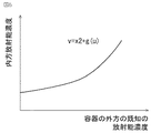
また同様に、試料11から放出される放射線も、外方検出部14に到達するまでに容器2を成す部材によって減衰されるけれども、完全に遮断することは困難である。したがって、前述の外方検出部14によって検出された外方検出結果は、容器2内に配置された試料11からの放射線の一部と、周辺放射線との合計値が検出されたものである。そこで、予め内方検出部12および外方検出部14に対する、試料11からの影響と周辺放射線からの影響とを実験によって調べ、試料11の放射能強度Rおよび周辺環境の放射能強度Rの算出に利用する第1関数g(u)と第2関数f(x)とを求める。第1関数g(u)は、容器2の外方における放射線量を変化させたときの内方放射能強度の変化を表す。第2関数f(x)は、容器2の内方の放射線量を変化させたときの外方放射能強度の変化を表す。第1関数g(u)および第2関数f(x)は、補正関数記憶部5に記憶させておく。
Similarly, the radiation emitted from the sample 11 is also attenuated by the members forming the
実験において、まず容器2内に配置された試料11の放射能強度Rを予め定める値x2に固定し、その条件下で容器2の外方における放射線量を変化させ、内方測定部3による測定結果である内方放射能強度の変化量を調べる。このとき、容器2の外方において線量を変化させる放射線は、放射能分析装置1の使用時における周辺放射線を模したものである。実験において、容器2の外方に設定される既知の放射能強度Rをuとし、内方測定部3による内方放射能強度をvとし、次式(6)で表される関数g(u)を決定する。この関数g(u)を第1関数と称する。
v=x2+g(u) ・・・(6)
実験は、シミュレーションによって行ってもよい。容器2の外方に設定される既知の放射能強度Rを変化させる方法については、放射性物質の量を変化させる方法であっても良いし、放射性物質からの距離を変化させる方法であっても良い。図5は、本発明の実施の形態1における第1関数g(u)の一例を表す図である。既知の試料11の放射能強度Rを、複数の異なる値に固定したときの第1関数g(u)についても同様に、実験によって決定しておく。
In the experiment, first, the radioactivity intensity R of the sample 11 placed in the
v = x2 + g (u) ・ ・ ・ (6)
The experiment may be performed by simulation. Regarding the method of changing the known radioactivity intensity R set on the outside of the
また、容器2の外方における放射能強度Rを予め定める値u1に固定し、その条件下で既知の試料11の放射線量を変化させ、外方測定部4による測定結果である外方放射能強度の変化量を調べる。既知の試料11の放射能強度Rをxとし、外方測定部4による外方放射能強度をyとし、次式(7)で表される関数f(x)を実験によって決定する。この関数f(x)を第2関数と称する。実験は、シミュレーションによって行ってもよい。
y=u1+f(x) ・・・(7)
既知の試料11の放射能強度Rは、放射性物質の量を変えることによって、変化させる。図6は、本発明の実施の形態1における第2関数f(x)の一例を表す図である。容器2の外方における放射線量を、複数の異なる値に固定したときの第2関数f(x)についても、実験によって決定しておく。
Further, the radioactivity intensity R on the outside of the
y = u1 + f (x) ・ ・ ・ (7)
The radioactivity intensity R of the known sample 11 is changed by changing the amount of radioactive material. FIG. 6 is a diagram showing an example of the second function f (x) according to the first embodiment of the present invention. The second function f (x) when the radiation amount outside the
次に、補正関数記憶部5に記憶される第1関数g(u)および第2関数f(x)を用いて、試料11の放射能強度Rと周辺環境の放射能強度Rとを求める計算について説明する。この計算は、補正演算部6によって行われる。放射能分析装置1を使用したときの内方測定部3の内方放射能強度をv1とし、外方測定部4の外方放射能強度をy2とする。求める周辺放射線の放射能強度Rをuとし、求める試料11の放射能強度Rをxとする。これらの値を前記式(6)および前記式(7)に代入すると、次式(8)および次式(9)が得られる。
v1=x+g(u) ・・・(8)
y2=u+f(x) ・・・(9)
Next, using the first function g (u) and the second function f (x) stored in the correction function storage unit 5, the calculation to obtain the radioactivity intensity R of the sample 11 and the radioactivity intensity R of the surrounding environment. Will be described. This calculation is performed by the
v1 = x + g (u) ・ ・ ・ (8)
y2 = u + f (x) ・ ・ ・ (9)
前記式(8)および前記式(9)において内方放射能強度v1および外方放射能強度y2は測定値として得られる値であり、前記式(8)および前記(9)は二元連立方程式となる。これを解くことによって、求める周辺放射線の放射能強度Rのuと、求める試料11の放射能強度Rのxとを得ることができる。この二元連立方程式を解くには、たとえばNewton法などを用いることができる。補正演算部6は、この演算をそれぞれのエネルギについて同様に実施することで、測定対象となるエネルギ範囲において、試料11の放射能強度Rおよび周辺環境の放射能強度Rの両方を求めることができる。補正演算部6が出力する結果は、表示部27にて表示される。
In the equations (8) and (9), the inner radioactivity intensity v1 and the outer radioactivity intensity y2 are values obtained as measured values, and the equations (8) and (9) are binary simultaneous equations. It becomes. By solving this, u of the required radioactivity intensity R of the peripheral radiation and x of the required radioactivity intensity R of the sample 11 can be obtained. For solving this binary simultaneous equation, for example, Newton's method can be used. By performing this calculation in the same manner for each energy, the
このような構成とすることによって、実施の形態1によれば、補正演算部6は、補正関数記憶部5に記憶される第1関数g(u)および第2関数f(x)を用い、内方放射能強度および外方放射能強度の両方に基づいて容器2内の試料11の放射能強度Rを演算する。したがって、周辺環境の放射線による内方測定部3への影響、および容器2の内方の放射線による外方測定部4への影響の両方に基づいて、容器2内の試料11の放射能強度Rを求めることができる。したがって、周辺環境から容器2の内方に到達する放射線量の多少に関わらず、容器2内の試料11の放射能強度Rを高い精度で測定できる。これによって、多様な周辺環境に対応できる。したがって汎用性の高い放射能分析装置1を実現できる。また容器2が周辺環境の放射線の透過を許容しても放射能強度Rの測定が可能なので、容器2を成す部材を放射線の遮蔽効果の高い、重量の大きい部材とする必要がない。したがって、容器2を軽量化できる。
With such a configuration, according to the first embodiment, the
また実施の形態1によれば、第1関数g(u)および第2関数f(x)を用いるので、容器2内の試料11の放射能強度Rに加えて周辺環境の放射能強度Rについても同時に演算することができる。
Further, according to the first embodiment, since the first function g (u) and the second function f (x) are used, in addition to the radioactivity intensity R of the sample 11 in the
実施の形態2.
次に、本発明の実施の形態2による放射能分析装置1Bを図に基づいて以下に説明する。実施の形態2は、先に説明した実施の形態1に類似しており、以下、実施の形態1に対する実施の形態2の相違点を中心に説明する。
Next, the radioactivity analyzer 1B according to the second embodiment of the present invention will be described below with reference to the drawings. The second embodiment is similar to the first embodiment described above, and the differences between the first and second embodiments will be mainly described below.
図7は、本発明の実施の形態2に係る放射能分析装置1Bの構成を表す図である。実施の形態1において外方測定部4は補正用波高分析部25を有するけれども、実施の形態2において外方測定部4は図7に示すように、補正用波高分析部25ではなくSCA(Single Channel Analyzer)部28を有する。測定対象の放射性核種が決まっており、周辺放射線の変動が小さく、かつ周辺環境に存在する放射性核種が分かっている場合には、SCAを用いることができる。
FIG. 7 is a diagram showing the configuration of the radioactivity analyzer 1B according to the second embodiment of the present invention. In the first embodiment, the
本実施の形態において外方測定部4は、内方測定部3とは異なり、外方検出部14から出力された外方検出結果から、予め定める下限値以上の波高かつ予め定める上限値以下の波高のパルス信号を抽出し、抽出した結果を用いて前記外方放射能強度を出力する。容器2の外方の周辺環境に存在する放射性核種、および外方検出部14に入射する放射線量は、予め分かっている場合が多い。その場合、外方検出部14から外方検出結果として出力されるパルス信号の波高は既知となる。したがって、外方検出結果の波高を予め定める下限値以上、予め定める上限値以下の範囲に限定して抽出することによって、目的とする放射性核種に係る放射能強度のみを選択的に利用する。
In the present embodiment, unlike the
具体的には、補正用波形整形部24から出力されるパルス信号は、SCA部28に入力される。周辺環境に存在する放射性核種の波高に合わせてSCA部28においてパルス信号の上限値と下限値を設定し、下限値以上かつ上限値以下のピーク値のパルス信号をカウントする。これによって、目的の放射性核種のパルス信号のみを選択してその放射線量を計測する。SCAを用いることによって、アナログ信号で処理できるので、回路構成を簡素化できる。
Specifically, the pulse signal output from the correction
実施の形態2によれば、外方算出部15が外方放射能強度の算出に利用する外方検出結果は、下限値以上の波高かつ上限値以下の波高のパルス信号である。周辺環境に存在する放射性核種が予め分かっている場合には、外方検出結果として出力されるパルス信号の波高は分かっているので、波高に下限値および上限値を定めてパルス信号を選択することによって、目的とする放射性核種に係る放射能強度Rを選択的に利用できる。また補正用波高分析部25ではなくSCA部28を用いることによって、アナログ信号で処理できるので、回路構成を簡素化できる。
According to the second embodiment, the outer detection result used by the
実施の形態3.
次に、本発明の実施の形態3による放射能分析装置1Cを図に基づいて以下に説明する。実施の形態3は、先に説明した実施の形態1に類似しており、以下、実施の形態1に対する実施の形態3の相違点を中心に説明する。
Next, the radioactivity analyzer 1C according to the third embodiment of the present invention will be described below with reference to the drawings. The third embodiment is similar to the first embodiment described above, and the differences between the first and third embodiments will be mainly described below.
図8は、本発明の実施の形態3に係る放射能分析装置1Cの構成を表す図である。外方測定部4は、シンチレーションファイバ部32と、第1検出部33と、第2検出部34と、第1波形整形部41と、第2波形整形部42と、時間情報取得部35と、位置判定部36と、合算部43と、減衰量補正部44と、補正用波高分析部25と、補正用応答関数記憶部31と、補正用信号復元部26とを有する。シンチレーションファイバ部32は、容器2の側面を全周にわたって包囲する。第1検出部33は、シンチレーションファイバ部32において発生したシンチレーション光を、シンチレーションファイバ部32の一方端部において検出する。第2検出部34は、シンチレーションファイバ部32において発生したシンチレーション光をシンチレーションファイバ部32の他方端部において検出する。
FIG. 8 is a diagram showing the configuration of the radioactivity analyzer 1C according to the third embodiment of the present invention. The
第1波形整形部41は、第1検出部33の外方検出結果を波形整形し第1整形後信号を出力する。第2波形整形部42は、第2検出部34の外方検出結果を波形整形し第2整形後信号を出力する。時間情報取得部35は、第1波形整形部41の第1整形後信号と第2波形整形部42の第2整形後信号とに基づいて、シンチレーション光が第1検出部33に到達した時刻と第2検出部34に到達した時刻との時間差を時間情報として取得する。位置判定部36は、時間情報取得部35が取得した時間情報からシンチレーション光の発生位置を判定する。合算部43は、第1整形後信号および第2整形後信号を合算する。これによって外方測定部4は、合算部43による合算の結果を用いて外方放射能強度を出力することになる。
The first
減衰量補正部44は、位置判定部36において判定した位置情報から、シンチレーション光が第1検出部33におよび第2検出部34に到達するまでに、伝播することによって減衰した減衰量を算出し、合算部43における合算の結果に対し、減衰量に応じた補正係数を乗算することによって、入射した周辺放射線のエネルギを決定する。減衰量補正部44から出力される補正後の結果は、補正用波高分析部25に入力される。補正用波高分析部25、補正用応答関数記憶部31、および補正用信号復元部26は、実施の形態1において説明したとおりである。
The attenuation correction unit 44 calculates the attenuation amount attenuated by propagating the scintillation light to the
上記のように構成された放射能分析装置1Cの外方測定部4を用いた、容器2の外方の放射能強度の測定について説明する。一般的に、試料11の放射能強度Rを高い精度で測定するためには、周辺放射線についても精度良く測定することが重要である。しかし、実施の形態1に示すように外方検出部14が容器2の外方の1箇所のみに設けられる場合には、周辺放射線の飛来方向に偏りがあるような環境において、周辺放射線の放射能強度Rを高い精度で測定できない場合がある。また、複数の外方検出部14を設けるという手段も考えられるけれども、構成が複雑になり、費用および重量の面で好ましくない。
The measurement of the outer radioactivity intensity of the
そこで、本実施の形態では、外方測定部の外方検出部14として、シンチレーションファイバ部32を用いる。シンチレーションファイバ部32に放射線が入射すると、入射した位置においてシンチレーション光が発生する。発生したシンチレーション光は、シンチレーションファイバ部32内を両端に向かって2つの向きに伝播し、第1検出部33および第2検出部34の両方に到達する。第1検出部33および第2検出部34に到達したシンチレーション光は、光電子倍増管によって増幅され、パルス信号として出力される。第1検出部33からのパルス信号は第1波形整形部41に入力され、波形整形が行われる。第2検出部34からのパルス信号は第2波形整形部42に入力され、波形整形が行われる。第1波形整形部41および第2波形整形部42で行われる波形整形の工程は、実施の形態1において説明した波形整形と同様である。
Therefore, in the present embodiment, the
第1波形整形部41および第2波形整形部42で波形整形された第1整形後信号および第2整形後信号は、時間情報取得部35に入力される。シンチレーションファイバ部32に入射することで発生したシンチレーション光は、発生した位置によって、第1検出部33および第2検出部34に到達するまでの時間が異なる。シンチレーション光が第1検出部33に到達する時刻と第2検出部34に到達する時刻との時間差を時間情報取得部35によって取得する。これには、時間波高変換器(TAC:Time−to−Amplitude Converter)などを用いることができる。
The first post-shaping signal and the second post-shaping signal that have been waveform-shaped by the first
位置判定部36では、時間情報取得部35において取得した時間の差異の情報から、シンチレーションファイバ部32におけるシンチレーション光の発生位置を判定する。これによって、シンチレーションファイバ部32への放射線の入射位置を判定できる。
The
次に、第1波形整形部41および第2波形整形部42から出力された第1整形後信号および第2整形後信号は、合算部43にも入力される。合算部43における第1整形後信号および第2整形後信号の合算は、シンチレーションファイバ部32に入射した1つの周辺放射線に対するシンチレーションファイバ部32の発光量を求める目的で行われるものである。
Next, the first post-shaping signal and the second post-shaping signal output from the first
シンチレーション光は、シンチレーションファイバ部32内を伝播する間に伝播する距離に応じて減衰する。減衰量補正部44では、位置判定部36において判定した位置情報から、伝播において減衰した減衰量を算出し、合算部43における合算の結果に対し、減衰量に応じた補正係数を乗算する。これによって減衰量補正部44は、シンチレーションファイバ部32に入射した周辺放射線のエネルギを決定し出力する。補正用波高分析部25は、シンチレーションファイバ部32への周辺放射線の入射が繰り返される度に、減衰量補正部44からの出力の受信を繰り返し、さらにその回数を計測する。これによって補正用波高分析部25は、複数の周辺放射線の入射に対して1つの波高分析結果、すなわち波高分布Mをスペクトルとして出力する。外方測定部4は、波高分布Mに対して実施の形態1と同様の処理を行うことによって、容器2の外方における放射能強度Rを求める。波高分布Mを求める工程以降は、実施の形態1と同様である。
The scintillation light is attenuated according to the propagating distance while propagating in the
このような構成とすることによって、実施の形態3によれば、第1検出部33および第2検出部34にシンチレーション光が到達した時刻からシンチレーション光の発生位置を算出できるので、周辺環境の放射線がいずれの方向からどの程度の強度で容器2に向かって飛来しているのかを測定できる。したがって周辺環境における放射線の飛来方向に偏りがある場合においても高い精度で周辺環境の放射能強度Rを演算できる。また周辺環境における放射線の飛来方向を検出するために、シンチレーション光を検出する多数の検出器を容器2の周囲に設ける必要がないので、簡素な構成を実現できる。したがって、シンチレーション光を検出する多数の検出器を容器2の周囲に設ける場合に比べて、重量および製作費用を低減できる。
With such a configuration, according to the third embodiment, the generation position of the scintillation light can be calculated from the time when the scintillation light reaches the
実施の形態4.
次に、本発明の実施の形態4による放射能分析装置1Dを図に基づいて以下に説明する。実施の形態4は、先に説明した実施の形態3に類似しており、以下、実施の形態3に対する実施の形態4の相違点を中心に説明する。
Next, the
図9は、本発明の実施の形態4に係る放射能分析装置1Dの構成を表す図である。本実施の形態においてシンチレーションファイバ部32は、束として形成された複数のシンチレーションファイバ37によって形成され、図9に示すように、容器2を覆う。このように、外方検出部14が検出器として、束として形成されたバンドルタイプのシンチレーションファイバ部32を有することによって、放射能分析装置1Dの運搬および携行を困難にすることなく簡素な構成を実現できる。また簡素な構成であるにも関わらず前述したように、周辺環境から放射線が飛来する方向をも検出することができる。したがって高い測定精度で試料11および周辺環境の放射能強度Rを測定できる。
FIG. 9 is a diagram showing the configuration of the
実施の形態1〜実施の形態4における容器2に関して、鉛等で遮蔽することにより2次的な放射線が発生する場合などは容器2の内側に、たとえば銅によって形成される遮蔽部材をさらに設けてもよい。
Regarding the
また前述したように実施の形態2では、外方測定部4は、外方検出部14から出力された外方検出結果から、予め定める下限値以上の波高かつ予め定める上限値以下の波高のパルス信号を抽出し、抽出した結果を用いて前記外方放射能強度を出力する。同様に実施の形態1における外方測定部4が、外方検出結果から、予め定める下限値以上の波高かつ予め定める上限値以下の波高のパルス信号を抽出し、抽出した結果を用いて前記外方放射能強度を出力する構成とすることもできる。この場合には、外方検出部14からの外方検出結果に予め下限値および上限値を定めて、補正用波形整形部24がパルス信号を抽出しても良いし、補正用波形整形部24から出力される波形整形後のパルス信号に対し、予め下限値および上限値を定めて、補正用波高分析部25がパルス信号を抽出しても良い。
Further, as described above, in the second embodiment, the
周辺環境に存在する放射性核種が予め分かっている場合であっても、外方検出結果においてピークが検出されるエネルギ値は1つとは限らず、複数のエネルギ値においてピークが検出される場合もある。したがって、補正用波高分析部25に多重波高分析器(MCA:Multi Channel Analyzer)を用いる場合には、いずれのエネルギ値のピークに下限値および上限値を設けるかを選択することができる。補正用波高分析部25がいずれのピークに下限値および上限値を設けるかは、周辺放射線の線量および外方検出部14の感度に応じて設定する。これによって外方測定部4は、周辺環境に存在する目的の放射性核種のパルス信号のみを選択してその放射線量を計測でき、上記実施の形態1も上記実施の形態2と同様の効果を奏する。
Even if the radionuclides present in the surrounding environment are known in advance, the energy value at which the peak is detected in the outer detection result is not limited to one, and the peak may be detected at a plurality of energy values. .. Therefore, when a multiple pulse height analyzer (MCA: Multi Channel Analyzer) is used for the correction
尚、それぞれの実施の形態は、本発明に係る技術を具体化するために例示するものであり、本発明の技術的範囲を限定するものではない。本発明は、その発明の範囲内において、各実施の形態を自由に組み合わせたり、各実施の形態を適宜、変形、省略することが可能である。 It should be noted that each embodiment is exemplified in order to embody the technique according to the present invention, and does not limit the technical scope of the present invention. In the present invention, each embodiment can be freely combined, and each embodiment can be appropriately modified or omitted within the scope of the invention.
1,1B,1C,1D 放射能分析装置、2 容器、3 内方測定部、
4 外方測定部、5 補正関数記憶部、6 補正演算部、11 試料、
12 内方検出部、13 内方算出部、14 外方検出部、15 外方算出部、
16 波形整形部、21 波高分析部、22 信号復元部、23 応答関数記憶部、
24 補正用波形整形部、25 補正用波高分析部、26 補正用信号復元部、
27 表示部、31 補正用応答関数記憶部、32 シンチレーションファイバ部、
33 第1検出部、34 第2検出部、35 時間情報取得部、36 位置判定部、
37 シンチレーションファイバ、41 第1波形整形部、42 第2波形整形部、
43 合算部、44 減衰量補正部。
1,1B, 1C, 1D radioactivity analyzer, 2 containers, 3 inner measuring section,
4 External measurement unit, 5 Correction function storage unit, 6 Correction calculation unit, 11 Samples,
12 Inner detection unit, 13 Inner calculation unit, 14 Outer detection unit, 15 Outer calculation unit,
16 Waveform shaping unit, 21 Wave height analyzer, 22 Signal restoration unit, 23 Response function storage unit,
24 Correction waveform shaping unit, 25 Correction wave height analysis unit, 26 Correction signal restoration unit,
27 Display unit, 31 Correction response function storage unit, 32 Scintillation fiber unit,
33 1st detection unit, 34 2nd detection unit, 35 time information acquisition unit, 36 position determination unit,
37 Scintillation fiber, 41 1st waveform shaping section, 42 2nd waveform shaping section,
43 Total part, 44 Attenuation amount correction part.
Claims (6)
前記容器の内方における放射線を検出し、内方放射能強度として出力する内方測定部と、
前記容器の外方における放射線を検出し、外方放射能強度として出力する外方測定部と、
前記容器の外方における放射線量を第1変数とし、該第1変数を変化させたときの前記内方放射能強度の変化を表す第1関数を含む第1式と、前記容器の内方における放射線量を第2変数とし、該第2変数を変化させたときの前記外方放射能強度の変化を表す第2関数を含む第2式と、を記憶する補正関数記憶部と、
前記内方測定部による測定値である前記内方放射能強度と、前記外方測定部による測定値である前記外方放射能強度と、を用いて前記補正関数記憶部に記憶される前記第1関数を含む前記第1式と前記第2関数を含む前記第2式との連立方程式を解き、前記第1式および前記第2式に含まれる前記第2変数の値を導出することにより、前記容器内の前記試料の放射能強度を演算する補正演算部とを備える放射能分析装置。 A container that houses the sample for which the radioactivity intensity is to be measured, and
An inner measuring unit that detects radiation inside the container and outputs it as the inner radioactivity intensity.
An external measuring unit that detects radiation on the outside of the container and outputs it as the external radioactivity intensity.
A first variable radiation dose at the outside of said container, a first expression including a first function representing a change in the inner radiation intensity when varying the first variable, inwardly before Symbol vessel A correction function storage unit that stores a second equation including a second function that represents a change in the outer radioactivity intensity when the second variable is changed, and a correction function storage unit that stores the radiation amount in
The first item stored in the correction function storage unit using the inner radioactivity intensity, which is a value measured by the inner measuring unit, and the outer radioactivity intensity, which is a value measured by the outer measuring unit. By solving the simultaneous equations of the first equation including one function and the second equation including the second function , and deriving the values of the second variable included in the first equation and the second equation. A radioactivity analyzer including a correction calculation unit that calculates the radioactivity intensity of the sample in the container.
前記第2関数は、前記第2変数を変化させたときの前記外方放射能強度の非線形性を有する変化を表し、The second function represents a non-linear change in the outer radioactivity intensity when the second variable is changed.
前記補正演算部は、非線形性を有する前記第1関数を含む前記第1式と、非線形性を有する前記第2関数を含む前記第2式との連立方程式を解くことにより、前記容器内の前記試料の放射能強度を演算する、The correction calculation unit solves the simultaneous equations of the first equation including the first function having non-linearity and the second equation including the second function having non-linearity, whereby the said in the container. Calculate the radioactivity intensity of the sample,
請求項1に記載の放射能分析装置。The radioactivity analyzer according to claim 1.
前記容器の外方における放射線を検出し、予め定める下限値以上の波高かつ予め定める上限値以下の波高のパルス信号を抽出し、抽出した結果を用いて前記外方放射能強度を出力する請求項1または請求項2に記載の放射能分析装置。 The outer measuring unit is
A claim that detects radiation outside the container, extracts a pulse signal having a wave height equal to or higher than a predetermined lower limit value and a wave height equal to or lower than a predetermined upper limit value, and outputs the outer radioactivity intensity using the extracted result. 1 or the radioactivity analyzer according to claim 2.
前記第1式と前記第2式との連立方程式を解き、前記第1式および前記第2式に含まれる前記第1変数の値を導出することにより、前記容器の外方における周辺環境の放射能強度を演算する請求項1から請求項3のいずれか1項に記載の放射能分析装置。 The correction calculation unit
By solving the simultaneous equations of the first equation and the second equation and deriving the values of the first variable included in the first equation and the second equation, the radiation of the surrounding environment outside the container. The radioactivity analyzer according to any one of claims 1 to 3, which calculates the ability intensity.
前記容器の側面を全周にわたって包囲するシンチレーションファイバ部と、
前記シンチレーションファイバ部において発生したシンチレーション光を、前記シンチレーションファイバ部の一方端部において検出する第1検出部と、
前記シンチレーションファイバ部において発生した前記シンチレーション光を、前記シンチレーションファイバ部の他方端部において検出する第2検出部と、
前記シンチレーション光が前記第1検出部に到達した時刻と前記第2検出部に到達した時刻との時間差を時間情報として取得する時間情報取得部と、
前記時間情報取得部が取得した前記時間情報から前記シンチレーション光の発生位置を判定する位置判定部と、
前記第1検出部による検出結果を波形整形し第1整形後信号を出力する第1波形整形部と、
前記第2検出部による検出結果を波形整形し第2整形後信号を出力する第2波形整形部と、
前記第1整形後信号および前記第2整形後信号を合算する合算部とを有し、
前記合算部による合算の結果を用いて前記外方放射能強度を出力する請求項4に記載の放射能分析装置。 The outer measuring unit is
A scintillation fiber portion that surrounds the side surface of the container over the entire circumference,
A first detection unit that detects scintillation light generated in the scintillation fiber unit at one end of the scintillation fiber unit, and
A second detection unit that detects the scintillation light generated in the scintillation fiber unit at the other end of the scintillation fiber unit, and
A time information acquisition unit that acquires the time difference between the time when the scintillation light reaches the first detection unit and the time when the scintillation light reaches the second detection unit as time information.
A position determination unit that determines the generation position of the scintillation light from the time information acquired by the time information acquisition unit, and a position determination unit.
A first waveform shaping unit that waveform-shapes the detection result by the first detection unit and outputs a signal after the first shaping,
A second waveform shaping unit that waveform-shapes the detection result by the second detection unit and outputs a signal after the second shaping,
It has a summing unit for summing the first post-shaping signal and the second post-shaping signal.
The radioactivity analyzer according to claim 4 , wherein the outer radioactivity intensity is output using the result of summing by the summing unit.
Priority Applications (1)
| Application Number | Priority Date | Filing Date | Title |
|---|---|---|---|
| JP2017130359A JP6872995B2 (en) | 2017-07-03 | 2017-07-03 | Radioactivity analyzer |
Applications Claiming Priority (1)
| Application Number | Priority Date | Filing Date | Title |
|---|---|---|---|
| JP2017130359A JP6872995B2 (en) | 2017-07-03 | 2017-07-03 | Radioactivity analyzer |
Publications (2)
| Publication Number | Publication Date |
|---|---|
| JP2019015509A JP2019015509A (en) | 2019-01-31 |
| JP6872995B2 true JP6872995B2 (en) | 2021-05-19 |
Family
ID=65357570
Family Applications (1)
| Application Number | Title | Priority Date | Filing Date |
|---|---|---|---|
| JP2017130359A Expired - Fee Related JP6872995B2 (en) | 2017-07-03 | 2017-07-03 | Radioactivity analyzer |
Country Status (1)
| Country | Link |
|---|---|
| JP (1) | JP6872995B2 (en) |
Families Citing this family (1)
| Publication number | Priority date | Publication date | Assignee | Title |
|---|---|---|---|---|
| FR3134635A1 (en) * | 2022-04-16 | 2023-10-20 | Commissariat à l'Energie Atomique et aux Energies Alternatives | Fiber sensor for analyzing the activity of a radioactive fluid |
Family Cites Families (10)
| Publication number | Priority date | Publication date | Assignee | Title |
|---|---|---|---|---|
| JP2007114067A (en) * | 2005-10-20 | 2007-05-10 | Wired Japan:Kk | Radiation detection system and radiation detection method |
| JP4139905B2 (en) * | 2005-12-16 | 2008-08-27 | 大学共同利用機関法人自然科学研究機構 | Radiation discrimination detector |
| JP4675244B2 (en) * | 2006-01-17 | 2011-04-20 | 三菱電機株式会社 | Radiation measurement system |
| JP4528268B2 (en) * | 2006-02-27 | 2010-08-18 | アロカ株式会社 | Scintillation detector and radiation detection apparatus |
| US8384017B2 (en) * | 2009-08-06 | 2013-02-26 | Schlumberger Technology Corporation | Subsurface nuclear measurement systems, methods and apparatus |
| JP5171891B2 (en) * | 2010-07-01 | 2013-03-27 | 三菱電機株式会社 | Radiation measurement equipment |
| US20120032087A1 (en) * | 2010-08-05 | 2012-02-09 | Wired Japan Co., Ltd. | Light collecting optical fiber, photodetection system, optical coupling structure and radio ray detection system |
| JP2014020902A (en) * | 2012-07-18 | 2014-02-03 | Ihi Construction Machinery Ltd | In-soil radioactivity distribution measuring instrument |
| JP6055222B2 (en) * | 2012-07-27 | 2016-12-27 | 株式会社熊谷組 | Radioactive material leak detector |
| JP5832404B2 (en) * | 2012-09-24 | 2015-12-16 | 三菱電機株式会社 | Radioactivity analyzer |
-
2017
- 2017-07-03 JP JP2017130359A patent/JP6872995B2/en not_active Expired - Fee Related
Also Published As
| Publication number | Publication date |
|---|---|
| JP2019015509A (en) | 2019-01-31 |
Similar Documents
| Publication | Publication Date | Title |
|---|---|---|
| KR101680067B1 (en) | Method and apparatus for distinguishing radionuclides using plastic scintillation detector | |
| JP5832404B2 (en) | Radioactivity analyzer | |
| JP5988890B2 (en) | Radioactivity analyzer and radioactivity analysis method | |
| JP5911585B2 (en) | Radioactivity analyzer | |
| CN103853929A (en) | Low-resolution gamma energy spectrum inversion analysis process and method based on Monte Carlo response matrix | |
| US11035963B2 (en) | Method for detecting radionuclide, process for detecting radionuclide using the same, and radiation detector for the same | |
| JP6872995B2 (en) | Radioactivity analyzer | |
| KR102313427B1 (en) | Method and apparatus for detecting radionuclides | |
| Reguigui | Gamma ray spectrometry | |
| JP6987086B2 (en) | Radioactivity measuring device | |
| JP6292004B2 (en) | β-ray detector | |
| JP2008122088A (en) | Radioactivity measuring device | |
| JP6037968B2 (en) | Radiation measurement apparatus and radiation measurement method | |
| JP5450356B2 (en) | Radiation detection method | |
| JP5926362B1 (en) | Radioactivity concentration measuring apparatus and radioactivity concentration measuring method | |
| JP6139391B2 (en) | Radioactivity inspection apparatus and method | |
| JPH1048342A (en) | Radioactivity measurement method | |
| JP7183206B2 (en) | Radioactivity inspection device | |
| JP2021032627A (en) | Radiation intensity distribution measuring device, radiation intensity distribution measuring method | |
| FR3104737A1 (en) | Method and system for evaluating a parameter representative of the mass uranium concentration of a sample of uranium material by gamma spectrometry | |
| JP7378377B2 (en) | Radiation analyzer and dust monitor device | |
| KR101192175B1 (en) | Energy Calibration Method of Gamma Ray Scintillation Counter | |
| KR102062450B1 (en) | A radiation detecting device usnig multi-photo-diode and a radiation detecting method usnig multi-photo-diode | |
| JP2019120656A (en) | Radiation measuring apparatus and radiation measurement method | |
| JP2018132392A (en) | Soil radioactive contamination inspection device |
Legal Events
| Date | Code | Title | Description |
|---|---|---|---|
| A621 | Written request for application examination |
Free format text: JAPANESE INTERMEDIATE CODE: A621 Effective date: 20191119 |
|
| RD02 | Notification of acceptance of power of attorney |
Free format text: JAPANESE INTERMEDIATE CODE: A7422 Effective date: 20191119 |
|
| A977 | Report on retrieval |
Free format text: JAPANESE INTERMEDIATE CODE: A971007 Effective date: 20200930 |
|
| A131 | Notification of reasons for refusal |
Free format text: JAPANESE INTERMEDIATE CODE: A131 Effective date: 20201027 |
|
| A521 | Request for written amendment filed |
Free format text: JAPANESE INTERMEDIATE CODE: A523 Effective date: 20201208 |
|
| TRDD | Decision of grant or rejection written | ||
| A01 | Written decision to grant a patent or to grant a registration (utility model) |
Free format text: JAPANESE INTERMEDIATE CODE: A01 Effective date: 20210323 |
|
| A61 | First payment of annual fees (during grant procedure) |
Free format text: JAPANESE INTERMEDIATE CODE: A61 Effective date: 20210420 |
|
| R151 | Written notification of patent or utility model registration |
Ref document number: 6872995 Country of ref document: JP Free format text: JAPANESE INTERMEDIATE CODE: R151 |
|
| LAPS | Cancellation because of no payment of annual fees |