JP6872000B1 - Wireless connector attachment / detachment method, robot device and wireless connector - Google Patents
Wireless connector attachment / detachment method, robot device and wireless connector Download PDFInfo
- Publication number
- JP6872000B1 JP6872000B1 JP2019226372A JP2019226372A JP6872000B1 JP 6872000 B1 JP6872000 B1 JP 6872000B1 JP 2019226372 A JP2019226372 A JP 2019226372A JP 2019226372 A JP2019226372 A JP 2019226372A JP 6872000 B1 JP6872000 B1 JP 6872000B1
- Authority
- JP
- Japan
- Prior art keywords
- transmission
- unit
- connector
- reception unit
- reception
- Prior art date
- Legal status (The legal status is an assumption and is not a legal conclusion. Google has not performed a legal analysis and makes no representation as to the accuracy of the status listed.)
- Active
Links
Images


Classifications
-
- B—PERFORMING OPERATIONS; TRANSPORTING
- B25—HAND TOOLS; PORTABLE POWER-DRIVEN TOOLS; MANIPULATORS
- B25J—MANIPULATORS; CHAMBERS PROVIDED WITH MANIPULATION DEVICES
- B25J19/00—Accessories fitted to manipulators, e.g. for monitoring, for viewing; Safety devices combined with or specially adapted for use in connection with manipulators
- B25J19/0025—Means for supplying energy to the end effector
- B25J19/0045—Contactless power transmission, e.g. by magnetic induction
-
- H—ELECTRICITY
- H02—GENERATION; CONVERSION OR DISTRIBUTION OF ELECTRIC POWER
- H02J—CIRCUIT ARRANGEMENTS OR SYSTEMS FOR SUPPLYING OR DISTRIBUTING ELECTRIC POWER; SYSTEMS FOR STORING ELECTRIC ENERGY
- H02J50/00—Circuit arrangements or systems for wireless supply or distribution of electric power
- H02J50/10—Circuit arrangements or systems for wireless supply or distribution of electric power using inductive coupling
-
- H—ELECTRICITY
- H02—GENERATION; CONVERSION OR DISTRIBUTION OF ELECTRIC POWER
- H02J—CIRCUIT ARRANGEMENTS OR SYSTEMS FOR SUPPLYING OR DISTRIBUTING ELECTRIC POWER; SYSTEMS FOR STORING ELECTRIC ENERGY
- H02J50/00—Circuit arrangements or systems for wireless supply or distribution of electric power
- H02J50/90—Circuit arrangements or systems for wireless supply or distribution of electric power involving detection or optimisation of position, e.g. alignment
Landscapes
- Engineering & Computer Science (AREA)
- Computer Networks & Wireless Communication (AREA)
- Power Engineering (AREA)
- Robotics (AREA)
- Mechanical Engineering (AREA)
- Manipulator (AREA)
- Details Of Connecting Devices For Male And Female Coupling (AREA)
Abstract
【課題】容易に修理することが可能な無線コネクタを提供する。【解決手段】無線コネクタは、第1対象物の外部から取り外し可能に取り付けられる第1ユニット106と、第2対象物の外部から取り外し可能に取り付けられる第2ユニット107とを備える。第1ユニットは、伝送対象を無線で伝送するための第1送受信部110、第1対象物に取り付けられることによって第1対象物との間で伝送対象を伝送するための第1コネクタ部109が固定された第1ハウジング108を含む。第2ユニットは、第1送受信部との間で伝送対象を無線で伝送するための第2送受信部114、及び、第2対象物に取り付けられることによって第2対象物との間で伝送対象を伝送するための第2コネクタ部113が固定された第2ハウジングとを含む。第1送受信部と第2送受信部とは、伝送対象を無線で伝送するように互いに離間して対向した状態で配置される。【選択図】図2PROBLEM TO BE SOLVED: To provide a wireless connector which can be easily repaired. A wireless connector includes a first unit 106 that is detachably attached from the outside of a first object and a second unit 107 that is detachably attached from the outside of a second object. The first unit includes a first transmission / reception unit 110 for wirelessly transmitting a transmission target, and a first connector unit 109 for transmitting a transmission target to and from the first object by being attached to the first object. Includes a fixed first housing 108. The second unit has a second transmission / reception unit 114 for wirelessly transmitting a transmission target to and from the first transmission / reception unit, and a transmission target to and from the second object by being attached to the second object. A second housing to which a second connector portion 113 for transmission is fixed is included. The first transmission / reception unit and the second transmission / reception unit are arranged in a state of being separated from each other and facing each other so as to transmit a transmission target wirelessly. [Selection diagram] Fig. 2
Description
本発明は、無線コネクタ着脱方法、ロボット装置及び無線コネクタに関する。 The present invention relates to a wireless connector attachment / detachment method, a robot device, and a wireless connector.
負荷に無線で電力を供給する技術が知られており、産業用ロボットなどに適用されている。例えば引用文献1には、図17(a)に示すように、ロボットアーム装置の関節部J2,J4のそれぞれに無線給電ユニットIHU2,IHU4を設ける例が開示されている。無線給電ユニットIHU2,IHU4は、一対のコイルを介して関節部J2,J4において電力を無線で伝送する。
The technology for wirelessly supplying electric power to a load is known and is applied to industrial robots and the like. For example,
無線給電ユニット100(無線給電ユニットIHU2に相当)は、図17(b)に示すように、送電装置10と受信装置20とを備える。送電装置10は、コイルなどを含む送電アンテナ11と、インバータ回路13、送電制御回路15とを備える。受信装置20は、コイルなどを含む受電アンテナ21と整流回路23とを備える。
As shown in FIG. 17B, the wireless power supply unit 100 (corresponding to the wireless power supply unit IHU2) includes a
一般的に、無線で電力を送受信するためのコイルは動作時に発熱することが多く、コイルの発熱に伴って無線給電ユニット100に不具合が生じることがある。無線給電ユニット100の不具合は、ロボットアーム装置の動作に支障をきたす場合があるので、無線給電ユニット100の交換などによって無線給電ユニット100を容易に修理できることが望ましい。
In general, a coil for transmitting and receiving electric power wirelessly often generates heat during operation, and the heat generated by the coil may cause a problem in the wireless
しかしながら、引用文献1では、一対のコイルの配置など無線給電ユニット100がどのように関節部J2,J4に設けられるかを開示していない。そのため、引用文献1を参照しても、容易に修理できる無線給電ユニット100を得ることは困難である。
However, Cited
本発明は、このような事情に鑑みてなされたものであって、容易に修理することが可能な無線コネクタの提供を目的とする。 The present invention has been made in view of such circumstances, and an object of the present invention is to provide a wireless connector that can be easily repaired.
上記目的を達成するため、本発明の第1の観点に係る無線コネクタ着脱方法は、
回転軸を支点にして回転可能に連結された第1対象物と第2対象物との間で、電力及び情報の少なくとも一方である伝送対象を無線で伝送するための無線コネクタを前記第1対象物及び前記第2対象物に着脱するための無線コネクタ着脱方法であって、
前記無線コネクタは、
前記伝送対象を無線で伝送するための第1送受信部、及び、前記第1対象物との間で前記伝送対象を伝送するための第1コネクタ部が固定された第1ハウジングと、
前記第1送受信部との間で前記伝送対象を無線で伝送するための第2送受信部、及び、前記第2対象物との間で前記伝送対象を伝送するための第2コネクタ部が固定された第2ハウジングとを備え、
前記第1対象物の外部から前記第1コネクタ部を前記第1対象物に取り付け、前記第2対象物の外部から前記第2コネクタ部を前記第2対象物に取り付けることによって、前記第1送受信部と前記第2送受信部とが前記伝送対象を無線で伝送するように互いに離間して対向した状態で前記第1対象物及び前記第2対象物に前記無線コネクタを取り付けることと、
前記第1対象物の外部での作業によって前記第1コネクタ部を前記第1対象物から取り外し、前記第2対象物の外部での作業によって前記第2コネクタ部を前記第2対象物から取り外すことによって、前記第1対象物及び前記第2対象物から前記無線コネクタを取り外すことを含む。
In order to achieve the above object, the wireless connector attachment / detachment method according to the first aspect of the present invention is
The first object is a wireless connector for wirelessly transmitting a transmission object which is at least one of power and information between a first object and a second object rotatably connected with a rotation axis as a fulcrum. A wireless connector attachment / detachment method for attaching / detaching to / from an object or the second object.
The wireless connector is
A first transmission / reception unit for wirelessly transmitting the transmission target, and a first housing in which a first connector portion for transmitting the transmission target with the first object is fixed.
A second transmission / reception unit for wirelessly transmitting the transmission target with the first transmission / reception unit and a second connector unit for transmitting the transmission target with the second transmission / reception object are fixed. With a second housing
The first transmission / reception is performed by attaching the first connector portion to the first object from the outside of the first object and attaching the second connector portion to the second object from the outside of the second object. Attaching the wireless connector to the first object and the second object in a state where the unit and the second transmitting / receiving unit are separated from each other and face each other so as to transmit the transmission object wirelessly.
Removing the first connector portion from the first object by working outside the first object, and removing the second connector portion from the second object by working outside the second object. Includes removing the wireless connector from the first object and the second object.
上記目的を達成するため、本発明の第2の観点に係るロボット装置は、
回転軸を支点にして回転可能に連結する関節機構を介して連結された第1アーム部及び第2アーム部と、
前記第1アーム部と前記第2アーム部との間で、電力及び情報の少なくとも一方である伝送対象を無線で伝送するための無線コネクタとを備え、
前記第1アーム部は、前記第1アーム部の外部に露出した第1相手コネクタ部を含み、
前記第2アーム部は、前記第2アーム部の外部に露出した第2相手コネクタ部を含み、
前記無線コネクタは、
前記伝送対象を無線で伝送するための第1送受信部、及び、前記第1相手コネクタ部に取り外し可能に取り付けられることによって前記第1アーム部との間で前記伝送対象を伝送するための第1コネクタ部が固定された第1ハウジングと、
前記第1送受信部との間で前記伝送対象を無線で伝送するための第2送受信部、及び、前記第2相手コネクタ部に取り外し可能に取り付けられることによって前記第2アーム部との間で前記伝送対象を伝送するための第2コネクタ部が固定された第2ハウジングとを含み、
前記第1送受信部と前記第2送受信部とは、前記第1コネクタ部と前記第2コネクタ部とがそれぞれ前記第1相手コネクタ部と前記第2相手コネクタ部とに取り付けられた場合に、前記関節機構の外部で前記伝送対象を無線で伝送するように前記回転軸に沿って互いに離間して対向した状態で配置される。
In order to achieve the above object, the robot device according to the second aspect of the present invention is
The first arm portion and the second arm portion connected via a joint mechanism rotatably connected with the rotation axis as a fulcrum,
A wireless connector for wirelessly transmitting a transmission target, which is at least one of electric power and information, is provided between the first arm portion and the second arm portion.
The first arm portion includes a first mating connector portion exposed to the outside of the first arm portion.
The second arm portion includes a second mating connector portion exposed to the outside of the second arm portion.
The wireless connector is
A first transmission / reception unit for wirelessly transmitting the transmission target and a first transmission target for transmitting the transmission target to and from the first arm unit by being detachably attached to the first mating connector unit. The first housing to which the connector is fixed and
The second transmission / reception unit for wirelessly transmitting the transmission target to and from the first transmission / reception unit, and the second arm unit by being detachably attached to the second mating connector unit. Including a second housing to which a second connector portion for transmitting a transmission target is fixed,
The first transmission / reception unit and the second transmission / reception unit are described when the first connector portion and the second connector portion are attached to the first mating connector portion and the second mating connector portion, respectively. It is arranged in a state of being separated from each other and facing each other along the rotation axis so that the transmission target is transmitted wirelessly outside the joint mechanism.
上記目的を達成するため、本発明の第3の観点に係る無線コネクタは、
回転軸を支点にして回転可能に連結された第1対象物と第2対象物との間で、電力である第1伝送対象を無線で伝送するための無線コネクタであって、
前記第1対象物の外部から前記第1対象物に取り外し可能に取り付けられる第1ユニットと、
前記第2対象物の外部から前記第2対象物に取り外し可能に取り付けられる第2ユニットとを備え、
前記第1ユニットは、
前記第1伝送対象を無線で伝送するための第1送受信部と、
前記第1対象物の外部から前記第1対象物に取り外し可能に取り付けられることによって前記第1対象物との間で前記第1伝送対象を伝送するための第1コネクタ部と、
前記第1送受信部と前記第1コネクタ部とが固定された第1ハウジングとを含み、
前記第2ユニットは、
前記第1送受信部との間で前記第1伝送対象を無線で伝送するための第2送受信部と、
前記第2対象物の外部から前記第2対象物に取り外し可能に取り付けられることによって前記第2対象物との間で前記第1伝送対象を伝送するための第2コネクタ部と、
前記第2送受信部と前記第2コネクタ部とが固定された第2ハウジングとを含み、
前記第1送受信部と前記第2送受信部とは、前記第1ユニット及び前記第2ユニットのそれぞれが前記第1対象物及び前記第2対象物に取り付けられた場合に、前記第1伝送対象を無線で伝送するように互いに離間して対向した状態で配置される。
In order to achieve the above object, the wireless connector according to the third aspect of the present invention is
A wireless connector for wirelessly transmitting a first transmission object, which is electric power, between a first object and a second object rotatably connected with a rotation axis as a fulcrum.
A first unit that is detachably attached to the first object from the outside of the first object,
A second unit that can be detachably attached to the second object from the outside of the second object is provided.
The first unit is
A first transmission / reception unit for wirelessly transmitting the first transmission target, and
A first connector portion for transmitting the first transmission object to and from the first object by being detachably attached to the first object from the outside of the first object.
The first housing to which the first transmission / reception portion and the first connector portion are fixed is included.
The second unit is
A second transmission / reception unit for wirelessly transmitting the first transmission target between the first transmission / reception unit and the first transmission / reception unit.
A second connector portion for transmitting the first transmission object to and from the second object by being detachably attached to the second object from the outside of the second object, and
A second housing to which the second transmission / reception portion and the second connector portion are fixed is included.
The first transmission / reception unit and the second transmission / reception unit transfer the first transmission target when the first unit and the second unit are attached to the first object and the second object, respectively. They are arranged so that they are separated from each other and face each other so as to transmit wirelessly.
前記第1送受信部は、前記第1伝送対象を伝送するための平板状の第1コイル部材を含み、
前記第2送受信部は、前記第1コイル部材と磁界結合することによって前記第1伝送対象を伝送するための平板状の第2コイル部材を含み、
前記第1コイル部材と前記第2コイル部材とは、前記第1ユニット及び前記第2ユニットのそれぞれが前記第1対象物及び前記第2対象物に取り付けられた場合に、前記第1伝送対象を無線で伝送するように互いに離間して対向した状態で平行に配置されてもよい。
The first transmission / reception unit includes a flat plate-shaped first coil member for transmitting the first transmission target.
The second transmission / reception unit includes a flat plate-shaped second coil member for transmitting the first transmission target by magnetically coupling with the first coil member.
The first coil member and the second coil member transfer the first transmission target when the first unit and the second unit are attached to the first object and the second object, respectively. They may be arranged in parallel in a state of being separated from each other and facing each other so as to be transmitted wirelessly.
前記第1ユニットは、
前記第1ハウジングに固定されており、情報である第2伝送対象を無線で伝送するための第3送受信部をさらに含み、
前記第2ユニットは、
前記第2ハウジングに固定されており、前記第3送受信部との間で前記第2伝送対象を無線で伝送するための第4送受信部をさらに含み、
前記第1コネクタ部は、前記第1対象物の外部から前記第1対象物に取り外し可能に取り付けられることによって前記第1対象物との間で前記第1伝送対象及び前記第2伝送対象を伝送し、
前記第2コネクタ部は、前記第2対象物の外部から前記第2対象物に取り外し可能に取り付けられることによって前記第2対象物との間で前記第1伝送対象及び前記第2伝送対象を伝送し、
前記第3送受信部と前記第4送受信部とは、前記第1ユニット及び前記第2ユニットのそれぞれが前記第1対象物及び前記第2対象物に取り付けられた場合に、前記第2伝送対象を無線で伝送するように互いに離間して対向した状態で配置されてもよい。
The first unit is
It is fixed to the first housing and further includes a third transmission / reception unit for wirelessly transmitting a second transmission target which is information.
The second unit is
It is fixed to the second housing, and further includes a fourth transmission / reception unit for wirelessly transmitting the second transmission target with the third transmission / reception unit.
The first connector portion transmits the first transmission target and the second transmission target to and from the first object by being detachably attached to the first object from the outside of the first object. And
The second connector portion transmits the first transmission target and the second transmission target to and from the second object by being detachably attached to the second object from the outside of the second object. And
The third transmission / reception unit and the fourth transmission / reception unit transfer the second transmission target when the first unit and the second unit are attached to the first object and the second object, respectively. They may be arranged so as to be separated from each other and opposed to each other so as to be transmitted wirelessly.
前記第3送受信部は、情報である前記第2伝送対象を伝送するための第1アンテナ部材を含み、
前記第4送受信部は、前記第2伝送対象を伝送するための第2アンテナ部材を含み、
前記第1送受信部は、前記第3送受信部の周囲に設けられ
前記第2送受信部は、前記第4送受信部の周囲に設けられ、
前記第1アンテナ部材と前記第2アンテナ部材とは、前記第1ユニット及び前記第2ユニットのそれぞれが前記第1対象物及び前記第2対象物に取り付けられた場合に、前記第2伝送対象を無線で伝送するように互いに離間して対向した状態で平行に配置されてもよい。
The third transmission / reception unit includes a first antenna member for transmitting the second transmission target, which is information.
The fourth transmission / reception unit includes a second antenna member for transmitting the second transmission target, and includes a second antenna member.
The first transmission / reception unit is provided around the third transmission / reception unit, and the second transmission / reception unit is provided around the fourth transmission / reception unit.
The first antenna member and the second antenna member transfer the second transmission target when the first unit and the second unit are attached to the first object and the second object, respectively. They may be arranged in parallel in a state of being separated from each other and facing each other so as to be transmitted wirelessly.
上記目的を達成するため、本発明の第4の観点に係る無線コネクタは、
回転軸を支点にして回転可能に連結された第1対象物と第2対象物との間で、伝送対象である電力及び情報の少なくとも一方を無線で伝送するための無線コネクタであって、
前記第1対象物の外部から前記第1対象物に取り外し可能に取り付けられる第1ユニットと、
前記第2対象物の外部から前記第2対象物に取り外し可能に取り付けられる第2ユニットとを備え、
前記第1ユニットは、
前記伝送対象を無線で伝送するための第1コイル部材を含む第1送受信部と、
前記第1対象物の外部から前記第1対象物に嵌め合わされることによって、前記第1対象物との間で前記伝送対象を伝送するように前記第1対象物に取り外し可能に取り付けられる第1コネクタ部と、
前記第1コイル部材と前記第1コネクタ部とが固定される第1ハウジングとを含み、
前記第2ユニットは、
前記第1コイル部材との間で前記伝送対象を無線で伝送するための第2コイル部材を含む第2送受信部と、
前記第2対象物の外部から前記第2対象物に嵌め合わされることによって、前記第2対象物との間で前記伝送対象を伝送するように前記第2対象物に取り外し可能に取り付けられる第2コネクタ部と、
前記第2コイル部材と前記第2コネクタ部とが固定される第2ハウジングとを含み、
前記第1コネクタ部と前記第2コネクタ部とは、嵌合方向が同じ方向であり、
前記第1コイル部材と前記第2コイル部材とは、前記嵌合方向に沿って互いに離間して対向した状態で配置されることによって磁界結合する。
In order to achieve the above object, the wireless connector according to the fourth aspect of the present invention is
A wireless connector for wirelessly transmitting at least one of electric power and information to be transmitted between a first object and a second object rotatably connected with a rotation axis as a fulcrum.
A first unit that is detachably attached to the first object from the outside of the first object,
A second unit that can be detachably attached to the second object from the outside of the second object is provided.
The first unit is
A first transmission / reception unit including a first coil member for wirelessly transmitting the transmission target, and a first transmission / reception unit.
A first that is detachably attached to the first object so as to transmit the transmission object to and from the first object by being fitted to the first object from the outside of the first object. Connector part and
A first housing to which the first coil member and the first connector portion are fixed is included.
The second unit is
A second transmission / reception unit including a second coil member for wirelessly transmitting the transmission target to and from the first coil member.
A second object that is detachably attached to the second object so as to transmit the transmission object to and from the second object by being fitted to the second object from the outside of the second object. Connector part and
A second housing to which the second coil member and the second connector portion are fixed is included.
The first connector portion and the second connector portion are fitted in the same direction.
The first coil member and the second coil member are magnetically coupled by being arranged in a state of being separated from each other and facing each other along the fitting direction.
前記第1コイル部材は、第1の中心軸の周りに配置されており、
前記第2コイル部材は、第2の中心軸の周りに配置されており、
前記第1の中心軸と前記第2の中心軸とは、前記嵌合方向と平行であってもよい。
The first coil member is arranged around the first central axis.
The second coil member is arranged around the second central axis.
The first central axis and the second central axis may be parallel to the fitting direction.
上記目的を達成するため、本発明の第5の観点に係る無線コネクタは、
回転軸を支点にして回転可能に連結された第1対象物と第2対象物との間で、伝送対象である電力及び情報の少なくとも一方を無線で伝送するための無線コネクタであって、
前記第1対象物の外部から前記第1対象物に取り外し可能に取り付けられる第1ユニットと、
前記第2対象物の外部から前記第2対象物に取り外し可能に取り付けられる第2ユニットとを備え、
前記第1ユニットは、
前記伝送対象を無線で伝送するための第1コイル部材を含む第1送受信部と、
前記第1対象物の外部から前記第1対象物に取り外し可能に取り付けられることによって前記第1対象物との間で前記伝送対象を伝送するための第1コネクタ部と、
前記第1送受信部と前記第1コネクタ部とが固定される第1ハウジングとを含み、
前記第2ユニットは、
前記第1送受信部との間で前記伝送対象を無線で伝送するための第2コイル部材を含む第2送受信部と、
前記第2対象物の外部から前記第2対象物に取り外し可能に取り付けられることによって前記第2対象物との間で前記伝送対象を伝送するための第2コネクタ部と、
前記第2送受信部と前記第2コネクタ部とが固定される第2ハウジングとを含み、
前記第1コイル部材と前記第2コイル部材とは、互いに離間して対向した状態で配置されることによって互いに磁界結合する。
In order to achieve the above object, the wireless connector according to the fifth aspect of the present invention is
A wireless connector for wirelessly transmitting at least one of electric power and information to be transmitted between a first object and a second object rotatably connected with a rotation axis as a fulcrum.
A first unit that is detachably attached to the first object from the outside of the first object,
A second unit that can be detachably attached to the second object from the outside of the second object is provided.
The first unit is
A first transmission / reception unit including a first coil member for wirelessly transmitting the transmission target, and a first transmission / reception unit.
A first connector portion for transmitting the transmission object to and from the first object by being detachably attached to the first object from the outside of the first object, and
Includes a first housing to which the first transmitter / receiver portion and the first connector portion are fixed.
The second unit is
A second transmission / reception unit including a second coil member for wirelessly transmitting the transmission target to and from the first transmission / reception unit.
A second connector portion for transmitting the transmission object to and from the second object by being detachably attached to the second object from the outside of the second object, and
A second housing to which the second transmission / reception portion and the second connector portion are fixed is included.
Wherein the first coil member and the second coil member, magnetically coupled to each other by being disposed so as to face at a distance from each other in each other physician.
前記第1送受信部と前記第2送受信部とは、前記第1ユニット及び前記第2ユニットのそれぞれが前記第1対象物及び前記第2対象物に取り付けられた場合に、前記回転軸に沿って互いに離間した状態で対向して配置されてもよい。 The first transmission / reception unit and the second transmission / reception unit are along the rotation axis when the first unit and the second unit are attached to the first object and the second object, respectively. They may be arranged so as to face each other while being separated from each other.
前記第1ユニットと前記第2ユニットとは、前記第1対象物及び前記第2対象物のそれぞれに取り付けられた場合に、互いに離間していてもよい。 The first unit and the second unit may be separated from each other when attached to each of the first object and the second object.
前記第1ユニットと前記第2ユニットとは、前記第1対象物及び前記第2対象物のそれぞれに取り付けられた場合に、前記第1送受信部と前記第2送受信部との相対的な位置関係を予め定められた範囲に制限するガイド機構をさらに含んでもよい。 When the first unit and the second unit are attached to the first object and the second object, respectively, the relative positional relationship between the first transmitter / receiver and the second transmitter / receiver. May further include a guide mechanism that limits the number to a predetermined range.
本発明によれば、無線コネクタを容易に修復することが可能になる。 According to the present invention, the wireless connector can be easily repaired.
以下、本発明の実施の形態に係る無線コネクタついて、図面を参照しつつ説明する。全図を通じて同一の要素には同一の符号を付す。 Hereinafter, the wireless connector according to the embodiment of the present invention will be described with reference to the drawings. The same elements are given the same reference numerals throughout the figure.
<<実施の形態1>>
(実施の形態1に係る無線コネクタ100の構成)
本発明の実施の形態1に係る無線コネクタ100は、図1の斜視図、図2の平面図、図3の分解斜視図に示すように、第1アーム部101と第2アーム部102との間で電力を無線で伝送するためのコネクタである。無線コネクタ100は、第1アーム部101と第2アーム部102との外部に着脱可能に取り付けられる。本実施の形態では、磁界結合(詳細には、電磁誘導)により無線で電力を伝送する例を説明する。
<<
(Configuration of
The
アーム部101,102は、産業用ロボット、人型ロボットなどのロボット装置において関節機構103を介して連結される。ここで、「アーム部101,102」は、第1アーム部101と第2アーム部102との総称であり、以下においても同様である。なお、アーム部101,102は、外殻OS1,OS2のそれぞれによって覆われており、これらの内部の機構や配線は露出していない。
The
関節機構103は、回転軸ARを支点にして回転可能に第1アーム部101と第2アーム部102とを連結する機構である。これにより、第1アーム部101と第2アーム部102とは、屈伸可能に連結される。
The
本実施の形態に係る関節機構103は、例えば、第2アーム部102に固定される軸部103Aと、第1アーム部101に設けられる孔部103Bとが互いに嵌り合うことで構成される。関節機構103は、軸部103Aの軸心を回転軸ARとして回転可能にアーム部101,102を連結する。
The
第1アーム部101と第2アーム部102とは、いずれが電源側であってもよいが、本実施の形態では、第1アーム部101が電源側であり、第2アーム部102が負荷側である例によって説明する。
Either the
例えば、第1アーム部101及び第2アーム部102が産業用ロボットに含まれる場合、関節機構103とは反対側の第1アーム部101の端部(図示せず)には、他の部材(他のアーム部、基台など)が接続される。また、関節機構103とは反対側の第2アーム部102の端部(図示せず)には、他の部材(他のアーム部、部品を挟み持つためのハンド部など)が接続される。
For example, when the
この場合の負荷は、例えば、第2アーム部102及びこれに接続される他の部材に搭載されるアクチュエータ、制御回路などであり、第1アーム部101と第2アーム部102とを回転させるために関節機構103に設けられるモータを含んでもよい。
The load in this case is, for example, an actuator, a control circuit, or the like mounted on the
以下の説明では、電気コネクタ100が取り付けられたアーム部101,102が真っ直ぐに伸びた状態で規定した上・下・前・後・右・左の方向を示す用語を用いる。
In the following description, the terms indicating the upper / lower / front / rear / right / left directions defined in the state where the
詳細には、回転軸ARに沿う方向を前後方向として規定し、アーム部101,102に沿う方向を左右方向とする。また、無線コネクタ100において電力を無線で伝送するために互いに対置される部位(後述する第1送受信部110及び第2送受信部114)が、アーム部101,102に対して位置する方向を前方とし、その反対方向を後方とする。上・下・左・右の各方向は、前方から見た方向に従って規定する。
Specifically, the direction along the rotation axis AR is defined as the front-rear direction, and the direction along the
ただし、これらの方向を示す用語は、説明のために用いるのであって、本発明を限定する趣旨ではない。 However, the terms indicating these directions are used for explanation and are not intended to limit the present invention.
第1アーム部101と第2アーム部102とは、それぞれ、第1相手コネクタ部104と第2相手コネクタ部105とを含む。第1相手コネクタ部104と第2相手コネクタ部105との各々は、無線コネクタ100との間で電力を伝送するためのコネクタであり、第1アーム部101と第2アーム部102とのそれぞれに外部に露出して設けられる。
The
本実施の形態に係る第1相手コネクタ部104と第2相手コネクタ部105との各々は、上下方向に間隔を開けて並べられた複数の電気接点を含むオス側の電気コネクタである。
Each of the first
詳細には、第1相手コネクタ部104は、回転軸ARの右方に設けられ、第1アーム部101の外殻OS1の前面から前方に突き出す。第2相手コネクタ部105は、回転軸ARの左方に設けられ、第2アーム部102の外殻OS2の前面から前方に突き出す。
Specifically, the first
図1〜3に示すように、無線コネクタ100は、第1アーム部101と第2アーム部102とのそれぞれに外部から着脱可能に取り付けられる第1ユニット106と第2ユニット107とを備える。
As shown in FIGS. 1 to 3, the
本実施の形態に係る第1ユニット106と第2ユニット107とは、互いに接触することなく離間している。そのため、第1ユニット106と第2ユニット107とは、第1アーム部101と第2アーム部102とのそれぞれに取り付けられると、回転軸ARを中心として相対的に回転することができる。
The
図1〜3及び後方から見た図4に示すように、第1ユニット106は、第1ハウジング108と、第1コネクタ部109と、第1送受信部110と、第1回路部111とを含む。なお、図4では、後述する第1ボルト128を図示省略している。
As shown in FIGS. 1 to 3 and 4 as viewed from the rear, the
図1〜3及び図5に示すように、第2ユニット107は、第1ユニット106に含まれる構成要素108〜111のそれぞれに対応する構成要素112〜115を含む。詳細には、第2ユニット107は、第2ハウジング112と、第2コネクタ部113と、第2送受信部114と、第2回路部115とを含む。なお、図5(a)及び(b)は、第2ユニット107を前方及び後方のそれぞれから見た図であって、これらでは後述する第2ボルト129を図示省略している。
As shown in FIGS. 1-3 and 5, the
第1ハウジング108と第2ハウジング112とは、第1ユニット106と第2ユニット107とのそれぞれに含まれる他の構成要素109〜111,113〜115が取り付けられる部材であって、典型的には中空の樹脂製である。
The
本実施の形態に係る第1ハウジング108は、第1アーム部101に取り付けるための第1アーム取付部120と、第1対置部121とを含む。第2ハウジング112は、第2アーム部102に取り付けるための第2アーム取付部122と、第1対置部121と互いに回転軸ARに沿って離間して対向した状態で配置される第2対置部123とを含む。
The
第1アーム取付部120と第2アーム取付部122との各々は、概ね直方体状の外形をなす。第1アーム取付部120と第2アーム取付部122とは、前後方向の長さを除いて概ね同じ大きさであって、前後方向の長さは第1アーム取付部120の方が第2アーム取付部122よりも長い。
Each of the first
詳細には、第1アーム取付部120は、第1開口124と4つの第1ボルト孔125とを含む。また、第2アーム取付部122は、第2開口126と4つの第2ボルト孔127とを含む。
Specifically, the first
第1開口124と第2開口126とは、第1アーム取付部120と第2アーム取付部122とのそれぞれの内部の空間を外部に接続するように後方の壁部に設けられる。第1開口124の内方(前方)と第2開口126の内方(前方)とには、それぞれ、詳細後述する第1コネクタ部109と第2コネクタ部113とが設けられる。
The
第1ボルト孔125と第2ボルト孔127との各々は、前後方向の貫通孔である。第1ボルト孔125には、第1ハウジング108を第1アーム部101に固定するための第1ボルト128が貫通した状態で配置される。第2ボルト孔127には、第2ハウジング112を第2アーム部102に固定するための第2ボルト129が貫通した状態で配置される。
Each of the
第1対置部121と第2対置部123とは、それぞれの基端が第1アーム取付部120の左端と第2アーム取付部122の右端とに接続し、互いに近接する方向に延びる平板状の部位である。これによって、第1対置部121と第2対置部123とは、回転軸ARに沿って互いに離間して対向する。
The first facing
詳細には、第1対置部121は、第1アーム取付部120の左端に基端が接続し、当該基端から前面を第1アーム取付部120の前面と面一にして左方へ延びる。第1対置部121は、第1アーム取付部120の高さと概ね同じ一定の高さで基端から延び、先端が前方から見て左方へ突き出た半円状をなす。ここで、「高さ」は、上下方向の長さであり、以下においても同様である。
Specifically, the
第2対置部123は、第2アーム取付部122の右端に基端が接続し、当該基端から前面を第2アーム取付部122の前面と面一にして右方へ延びる。第2対置部123は、第2アーム取付部122の高さと概ね同じ一定の高さで基端から延び、先端が前方から見て右方へ突き出た半円状をなす。
The second
第1対置部121の厚さは、第1アーム取付部120と第2アーム取付部122との厚さの差よりも薄い。これにより、第1対置部121の先端は第2対置部123の前方に間隔を空けて配置される。そして、第1対置部121と第2対置部123とは、各々の先端を含む概ね円形の領域が関節機構103の外部で回転軸ARに沿って互いに離間して対向した状態で配置される。第2対置部123の厚さは、適宜設定されてよいが、第2アーム取付部122よりも薄く、本実施の形態では第1対置部121の厚さと概ね同じである。ここで、「厚さ」は、前後方向の長さであり、以下においても同様である。
The thickness of the first facing
第1コネクタ部109は、第1アーム部101との間で電力を伝送するための部位である。第1コネクタ部109は、第1アーム部101の外部から第1アーム部101に取り外し可能に取り付けられる。第1コネクタ部109は、第1相手コネクタ部104に取り付けられることによって、第1アーム部101との間で電力を伝送する。
The
本実施の形態に係る第1コネクタ部109は、第1ハウジング108に固定されたメス側の電気コネクタであり、第1開口124の前方にて上下方向に間隔を開けて並べられた複数の電気接点を含む。これにより、第1コネクタ部109は、第1開口124を通じて第1ハウジング108の外部に露出するので、第1ハウジング108の後方から第1開口124を通じて差し込まれた第1相手コネクタ部104と前後方向に互いに嵌り合う。互いに嵌り合った第1コネクタ部109と第1相手コネクタ部104とは、それぞれの電気接点が接触することによって互いに電気的に接続し、電力を伝送することができる。
The
なお、第1コネクタ部109と第1相手コネクタ部104とのメス側とオス側との関係は、入れ替えられてもよい。第1相手コネクタ部104は、メス側である場合も第1アーム部101の外部に露出していればよく、これによって、第1アーム部101の外部から第1コネクタ部109を取り外し可能に取り付けることができる。具体的には例えば、第1アーム部101の外殻OS1に開口を設け、第1相手コネクタ部104を構成する電気接点が当該開口の内方に設けられればよい。
The relationship between the female side and the male side of the
第2コネクタ部113は、第2アーム部102との間で電力を伝送するための部位である。第2コネクタ部113は、第2アーム部102の外部から第2アーム部102に取り外し可能に取り付けられる。第2コネクタ部113は、第2相手コネクタ部105に取り付けられることによって、第2アーム部102との間で電力を伝送する。
The
本実施の形態に係る第2コネクタ部113は、第2ハウジング112に固定されたメス側の電気コネクタであり、第2開口126の前方にて上下方向に間隔を開けて並べられた複数の電気接点を含む。これにより、第2コネクタ部113は、第2開口126を通じて第2ハウジング112の外部に露出するので、第2ハウジング112の後方から第2開口126を通じて差し込まれた第2相手コネクタ部105と前後方向に互いに嵌り合う。互いに嵌り合った第2コネクタ部113と第2相手コネクタ部105とは、それぞれの電気接点が接触することによって互いに電気的に接続し、電力を伝送することができる。
The
なお、第2コネクタ部113と第2相手コネクタ部105とのメス側とオス側との関係は、入れ替えられてもよい。第2相手コネクタ部105は、メス側である場合も第2アーム部102の外部に露出していればよく、これによって、第2アーム部102の外部から第2コネクタ部113を取り外し可能に取り付けることができる。具体的には例えば、第2アーム部102の外殻OS2に開口を設け、第2相手コネクタ部105を構成する電気接点が当該開口の内方に設けられればよい。
The relationship between the female side and the male side of the
第1送受信部110と第2送受信部114とは、これらの間で電力を無線で伝送するための部材であって、電力を無線で伝送するように関節機構103の外部で回転軸ARに沿って互いに離間して対向した状態で配置される。典型的には、第1送受信部110と第2送受信部114とは、それぞれ、第1の中心軸C1と第2の中心軸C2とを中心とする形状であり、例えば円板状である。
The first transmission /
本実施の形態では、第1送受信部110は、その外縁が第1対置部121の先端と概ね一致するように、第1対置部121の後方の外面に例えば接着剤、ビスなどで固定される。第2送受信部114は、その外縁が第2対置部123の先端と概ね一致するように、第2対置部123の前方の外面に例えば接着剤、ビスなどで固定される。
In the present embodiment, the first transmission /
これにより、第1送受信部110と第2送受信部114とは、第1対置部121と第2対置部123とのそれぞれの回転軸ARに沿って互いに対向する領域に固定される。従って、第1送受信部110と第2送受信部114とは、関節機構103の外部で回転軸ARに沿って互いに対向して配置される。また、第1送受信部110と第2送受信部114とは、互いに接触することなく離間した状態で配置され、好ましくは、回転軸ARに対して垂直な方向を向けて互いに平行に配置される。
As a result, the first transmission /
本実施の形態に係る第1送受信部110と第2送受信部114とは、それぞれ、概ね同じ大きさの円板状の第1コイル部材と第2コイル部材である。すなわち、第1コイル部材は、第1の中心軸C1を中心とする円板状である。第2コイル部材は、第2の中心軸C2を中心とする円板状である。
The first transmission /
第1コイル部材と第2コイル部材との各々は、例えば、中心軸C1又はC2の周りに渦巻き状に巻き回された導線、中心軸C1又はC2の周りに渦巻き状に基板に印刷されたプリント配線などによって構成されるとよい。 Each of the first coil member and the second coil member is, for example, a conductor wound spirally around the central axis C1 or C2, and a printed circuit board printed spirally around the central axis C1 or C2. It may be composed of wiring or the like.
第1コイル部材と第2コイル部材とは、回転軸ARに沿って互いに対向した状態で配置されるので、電磁誘導によって磁界結合する。これにより、第1コイル部材と第2コイル部材との間で電力を無線で伝送することができる。 Since the first coil member and the second coil member are arranged so as to face each other along the rotation axis AR, they are magnetically coupled by electromagnetic induction. As a result, electric power can be wirelessly transmitted between the first coil member and the second coil member.
ここで、第1送受信部110と第2送受信部114とは、これらの間の結合(本実施の形態では、磁界結合)を強くするには、互いに対向する領域の面積(対向面積)は大きい方が望ましく、3つの軸AR,C1,C2は、一致することが望ましい。しかし、第1送受信部110と第2送受信部114とは、電力を伝送するように(本実施の形態では、磁界結合するように)回転軸ARに沿って互いに対向した状態で配置されればよく、3つの軸AR,C1,C2が製造誤差、設計上の制約などによってズレていてもよい。
Here, in order to strengthen the coupling between the first transmission /
また、本実施の形態では、第1送受信部110の前方と第2送受信部114の後方とのそれぞれには、金属、軟磁性体などで作られたシート状のシールド部材S1,S2が設けられている。これにより、第1送受信部110と第2送受信部114とが回転軸ARに沿ってシールド部材S1,S2に挟まれるので、外部へ放出される電磁波などを抑制することができる。
Further, in the present embodiment, sheet-shaped shield members S1 and S2 made of metal, soft magnetic material, or the like are provided at the front of the first transmission /
なお、第1送受信部110は、第1コイル部材に直列又は並列に接続されるコンデンサなどをさらに含んでもよく、第1コイル部材などが収容される樹脂製のケースをさらに含んでもよい。第2送受信部114も同様に、第2コイル部材に直列又は並列に接続されるコンデンサなどをさらに含んでもよく、第2コイル部材などが収容される樹脂製のケースをさらに含んでもよい。
The first transmission /
第1回路部111は、第1コネクタ部109と第1送受信部110とに電気的に接続される電気回路である。第1回路部111は、第1コネクタ部109と第1送受信部110との各々と互いに電気的に接続した状態で第1ハウジング108の内部に固定されている。
The
本実施の形態では、第1回路部111は、第1コネクタ部109の前端に固定されており、第1送受信部110とは第1導線130を介して互いに電気的に接続している。
In the present embodiment, the
また本実施の形態では、上述の通り、第1アーム部101が電源側である。そのため、第1回路部111は、送電回路であり、例えば、第1アーム部101から第1コネクタ部109を通じて供給された電力を第1送受信部110へ出力するための電力に変換するインバータ回路などを含む。
Further, in the present embodiment, as described above, the
第2回路部115は、第2コネクタ部113と第2送受信部114とに電気的に接続される電気回路である。第2回路部115は、第2コネクタ部113と第2送受信部114との各々と互いに電気的に接続した状態で第2ハウジング112の内部に固定されている。
The
本実施の形態では、第2回路部115は、第2コネクタ部113の前端に固定されており、第2送受信部114とは第1導線131を介して互いに電気的に接続している。
In the present embodiment, the
また本実施の形態では、上述の通り、第2アーム部102が負荷側である。そのため、第2回路部115は、受電回路であり、例えば、第1送受信部110と磁界結合した第2送受信部114によって受信された電力を第2コネクタ部113を通じて第2アーム部102へ出力するための電力に変換する整流・平滑回路を含む。
Further, in the present embodiment, as described above, the
これまで、本発明の実施の形態1に係る無線コネクタ100の構成について説明した。
So far, the configuration of the
一般的に、第1ユニット106と第2ユニット107とは、製造誤差などによって、アーム部101,102に取り付けられた場合に、設計上の回転軸(例えば、第1の中心軸C1と第2の中心軸C2とに一致する軸)が回転軸ARに一致しない可能性がある。本実施の形態に係る第1ユニット106と第2ユニット107とは、上述の通り互いに接触することなく離間している。そのため、設計上の回転軸が回転軸ARからズレていても、アーム部101,102の屈曲に伴って回転軸ARを中心に回転することができる。
Generally, when the
また、第1ユニット106と第2ユニット107とは、互いに接触することなく離間している。そのため、相対的に回転しても摩耗することが殆どなく、電気コネクタ100の耐久性を向上させることが可能になる。
Further, the
(実施の形態1に係る無線コネクタ100の動作)
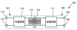
ここから、本実施の形態に係る無線コネクタ100の動作について、図6の回路構成図を参照して説明する。
(Operation of the
From here, the operation of the
第1アーム部101(電源側)から供給された電力は、図6に示すように、第1コネクタ部109と第1回路部111とを通じて第1送受信部110に供給される。これにより、第1送受信部110に交流電流が流れて、第1送受信部110の周囲に磁界が生じる。
As shown in FIG. 6, the electric power supplied from the first arm unit 101 (power supply side) is supplied to the first transmission /
第1送受信部110と第2送受信部114とは、上述したように、回転軸ARに沿って互いに離間して対向した状態で配置される。そのため、第1送受信部110と第2送受信部114とは磁界結合し、第1送受信部110の周囲に発生した磁界に応じた誘導起電力が第2送受信部114に発生する。すなわち、本実施の形態では、第1送受信部110を構成する第1コイル部材が送電コイルとして機能し、第2送受信部114を構成する第2コイル部材が受電コイルとして機能する。
As described above, the first transmission /
第2送受信部114に発生した電力は、第2回路部115と第2コネクタ部113とを通じて、第2アーム部102(負荷側)へ供給される。このように、無線コネクタ100によって、第1アーム部101と第2アーム部102との間で電力を無線で伝送することができる。
The electric power generated in the second transmission /
本実施の形態では、上述の通り、アーム部101,102が回転軸ARを支点として回転することで屈伸し、これに伴って、第1ユニット106と第2ユニット107とは回転軸ARを中心に回転する。
In the present embodiment, as described above, the
送受信部110,114は、回転軸ARに沿って互いに離間して対向した状態で配置されるので、第1ユニット106と第2ユニット107とが回転した場合においても、電磁誘導によって磁界結合する。そのため、アーム部101,102の屈伸の状態に関わらず、またアーム部101,102が屈伸の動作中であっても、無線コネクタ100は、上述した動作と同様に動作することができるので、第1アーム部101と第2アーム部102との間で電力を無線で伝送することができる。ここで、「送受信部110,114」は、第1送受信部110と第2送受信部114との総称であり、以下においても同様である。
Since the transmission /
好ましくは、送受信部110,114は、相対的な位置関係を制限した状態で配置される。すなわち、送受信部110,114は、回転軸ARを中心として回転した場合においても、これらの相対的な位置関係が予め定められた範囲となるように配置される。
Preferably, the transmission /
ここで、送受信部110,114の相対的な位置関係とは、送受信部110,114が回転軸ARに沿って離間する距離(離間距離)、互いに対向する領域の面積(対向面積)、回転軸ARに対してなす角度などである。実施の形態において送受信部110,114が互いに平行に配置されることは、相対的な位置関係を制限した状態で配置されることの一例である。
Here, the relative positional relationship between the transmission /
送受信部110,114の相対的な位置関係を制限することによって、送受信部110,114は、アーム部101,102の屈伸状態及び屈伸動作に関わらず、予め定められた範囲の比較的安定した強さで磁界結合することができる。従って、アーム部101,102の外部に無線コネクタ100を配置した場合であっても、無線での安定した電力の伝送が可能になる。
By limiting the relative positional relationship between the transmission /
(実施の形態1に係る無線コネクタ着脱方法)
これまで、本発明の実施の形態1に係る無線コネクタ100の動作について説明した。ここから、本実施の形態に係る無線コネクタ着脱方法について、図7〜8を参照して説明する。
(Method of attaching / detaching the wireless connector according to the first embodiment)
So far, the operation of the
本実施の形態に係る無線コネクタ着脱方法は、無線コネクタ100をアーム部101,102に着脱するための方法であって、無線コネクタ100の取り付け方法と取り外し方法とを含む。
The wireless connector attachment / detachment method according to the present embodiment is a method for attaching / detaching the
(無線コネクタ100の取り付け方法)
図7は、無線コネクタ100の取り付け方法の流れを示すフローチャートである。無線コネクタ100の取り付け方法は、関節機構103を介して連結されたアーム部101,102を含むロボット装置と、無線コネクタ100とを準備して開始される。
(How to attach the wireless connector 100)
FIG. 7 is a flowchart showing a flow of a method of attaching the
図7に示すように、第2ユニット107が第2アーム部102の外部から第2アーム部102に取り付けられる(工程1;第2ユニットの取り付け工程)。
As shown in FIG. 7, the
詳細には、工程1において、第2送受信部114が回転軸AR上で関節機構103の前方に位置付けられた状態で、第2コネクタ部113が、第2アーム部102に取り付けられる(工程1A;第2コネクタ部の取り付け工程)。
Specifically, in
本実施の形態では、第2相手コネクタ部105を嵌め込むことによって、第2コネクタ部113は、第2アーム部102に取り付けられる。第2相手コネクタ部105は第2アーム部102の外部に露出しているので、第2コネクタ部113は、第2アーム部102の外部から第2アーム部102に取り付けられる。
In the present embodiment, the
このように第2コネクタ部113が取り付けられることによって、第2コネクタ部113と第2相手コネクタ部105とが電気的に接続する。また本実施の形態では、第2コネクタ部113が第2ハウジング112に固定されているので、第2ハウジング112は、第2コネクタ部113とともに第2アーム部102に取り付けられる。これにより、第2ユニット107が第2アーム部102に取り付けられる。
By attaching the
図7に示すように、第2ユニット107が第2アーム部102に固定される(工程1B;固定工程)。
As shown in FIG. 7, the
本実施の形態では、第2ボルト129を第2ボルト孔127の各々に挿入して、第2アーム部102に設けられた第2ボルト穴部132にネジ作用で嵌めることによって、第2ハウジング112が第2アーム部102に固定される。なお、第2ユニット107を第2アーム部102に固定する方法は、ボルト止めに限られず、例えば爪と第2開口126の周辺部との引っ掛かりによる係止などであってもよい。
In the present embodiment, the
図7に示すように、第1ユニット106が第1アーム部101の外部から第1アーム部101に取り付けられる(工程2;第1ユニットの取り付け工程)。
As shown in FIG. 7, the
詳細には、工程2において、第1送受信部110が回転軸AR上で関節機構103及び第2送受信部114の前方に位置付けられた状態で、第1コネクタ部109が、第1アーム部101に取り付けられる(工程2A;第1コネクタ部の取り付け工程)。
Specifically, in
本実施の形態では、第1相手コネクタ部104を嵌め込むことによって、第1コネクタ部109は、第1アーム部101に取り付けられる。第1相手コネクタ部104は第1アーム部101の外部に露出しているので、第1コネクタ部109は、第1アーム部101の外部から第1アーム部101に取り付けられる。
In the present embodiment, the
このように第1コネクタ部109が取り付けられることによって、第1コネクタ部109と第1相手コネクタ部104とが電気的に接続する。また本実施の形態では、第1コネクタ部109が第1ハウジング108に固定されているので、第1ハウジング108は、第1コネクタ部109とともに第1アーム部101に取り付けられる。これにより、第1ユニット106が第1アーム部101に取り付けられる。
By attaching the
図7に示すように、第1ユニット106が第1アーム部101に固定される(工程2B;固定工程)。
As shown in FIG. 7, the
本実施の形態では、第1ボルト128を第1ボルト孔125の各々に挿入して、第1アーム部101に設けられた第1ボルト穴部133にネジ作用で嵌めることによって、第1ハウジング108が第1アーム部101に固定される。なお、第1ユニット106を第1アーム部101に固定する方法は、ボルト止めに限られず、例えば爪と第1開口124の周辺部との引っ掛かりによる係止などであってもよい。
In the present embodiment, the
これにより、無線コネクタ100の取り付け方法が終了し、電気コネクタ100は、第1アーム部101及び第2アーム部102に固定した状態で取り付けられる。また、送受信部110,114は、電力を無線で伝送するように関節機構103の外部で回転軸ARに沿って互いに離間して対向した状態で、回転軸ARに対して概ね垂直な方向を向いて概ね平行に配置される。
As a result, the method of attaching the
(無線コネクタ100の取り外し方法)
図8は、無線コネクタ100の取り外し方法の流れを示すフローチャートである。無線コネクタ100の取り外し方法は、典型的には、上述した無線コネクタ100の取り付け方法によって無線コネクタ100をロボット装置に取り付けた後に、必要に応じて行われる。無線コネクタ100の取り外しが必要な場合の例としては、不具合が生じた無線コネクタ100を修理するために、正常な無線コネクタ100に交換する場合などを挙げることができる。
(How to remove the wireless connector 100)
FIG. 8 is a flowchart showing a flow of a method of removing the
図8に示すように、第1ユニット106が第1アーム部101の外部での作業によって第1アーム部101から取り外される(工程3;第1ユニットの取り外し工程)。
As shown in FIG. 8, the
詳細には、図8に示すように、第1ユニット106と第1アーム部101との固定が解かれる(工程3A;固定の解除工程)。本実施の形態では、第1ボルト128と第1ボルト穴部133とのネジ作用による嵌り合いを解いた後に、第1ボルト128が第1ボルト孔125から取り外される。
Specifically, as shown in FIG. 8, the fixing between the
図8に示すように、第1コネクタ部109が第1アーム部101から取り外される(工程3B;第1コネクタ部の取り外し工程)。
As shown in FIG. 8, the
本実施の形態では、例えば第1アーム部101の外部で作業者が手や治具などを用いて第1ハウジング108を把持する。そして、第1コネクタ部109を第1相手コネクタ部104から引く抜くことで、第1コネクタ部109が第1アーム部101から取り外される。
In the present embodiment, for example, an operator grips the
本実施の形態では第1コネクタ部109が第1ハウジング108に固定されているので、第1ハウジング108は、第1コネクタ部109とともに第1アーム部101から取り外される。これにより、第1ユニット106が、第1アーム部101から取り外される。
In the present embodiment, since the
図8に示すように、第2ユニット107が第2アーム部102の外部での作業によって第2アーム部102から取り外される(工程4;第2ユニットの取り外し工程)。
As shown in FIG. 8, the
詳細には、図8に示すように、第2ユニット107と第2アーム部102との固定が解かれる(工程4A;固定の解除工程)。本実施の形態では、第2ボルト129と第2ボルト穴部132とのネジ作用による嵌り合いを解いた後に、第2ボルト129が第2ボルト孔127から取り外される。
Specifically, as shown in FIG. 8, the fixing of the
図8に示すように、第2コネクタ部113が第2アーム部102から取り外される(工程4B;第2コネクタ部の取り外し工程)。
As shown in FIG. 8, the
本実施の形態では、例えば第2アーム部102の外部で作業者が手や治具などを用いて第2ハウジング112を把持する。そして、第2コネクタ部113を第2相手コネクタ部105から引く抜くことで、第2コネクタ部113が第2アーム部102から取り外される。
In the present embodiment, for example, an operator grips the
本実施の形態では第2コネクタ部113が第2ハウジング112に固定されているので、第2ハウジング112は、第2コネクタ部113とともに第1アーム部101から取り外される。これにより、第2ユニット107が、第2アーム部102から取り外される。
In the present embodiment, since the
無線コネクタ100の取り外し方法が終了し、無線コネクタ100がアーム部101,102から取り外される。
The method of removing the
これまで、本発明の実施の形態1について説明した。
So far,
本実施の形態によれば、アーム部101,102の外部での作業によって無線コネクタ100をアーム部101,102に着脱することができる。これにより、例えば、不具合が生じた無線コネクタ100を正常な無線コネクタ100に容易に交換することができる。従って、無線コネクタ100を容易に修理することが可能になる。
According to this embodiment, the
また、無線コネクタ100は、アーム部101,102の外部に配置された状態でアーム部101,102に取り付けられる。そのため、アーム部101,102の内部に設けられる場合よりも、アーム部101,102の内部の設計への影響が少なくなる。従って、アーム部101,102の設計の自由度を向上させることが可能になる。
Further, the
また本実施の形態では、第1コネクタ部109と第1相手コネクタ部104との嵌合方向と、第2コネクタ部113と第2相手コネクタ部105との嵌合方向とは、いずれも同じ前後方向である。そして、送受信部110,114は、当該嵌合方向に沿って互いに離間して対向した状態で配置されることによって磁界結合する。
Further, in the present embodiment, the mating direction between the
この場合、アーム部101,102においては、関節機構103の回転軸ARを介して互いに反対の方向に第1相手コネクタ部104及び第2相手コネクタ部105を設ければよい。そのため、第1相手コネクタ部104及び第2相手コネクタ部105を容易に設けることができる。また、無線コネクタ100においては、上述の構成の説明から分かるように、第1ユニット106及び第2ユニット107の構成を比較的簡易にすることができる。
In this case, the
従って、無線コネクタ100を簡易な構成として、アーム部101,102に容易に設けることが可能になる。
Therefore, the
さらに本実施の形態によれば、第1の中心軸C1と第2の中心軸C2とは、平行な前後方向を向いており、第1コネクタ部109及び第2コネクタ部113の嵌合方向と平行である。これにより、簡易な構成で、第1送受信部110(第1コイル部材)と第2コネクタ部113(第2コイル部材)とを概ね互いに平行に配置して、良好に磁界結合させることができる。従って、簡易な構成で、かつ、良好に無線で電力を伝送することが可能になる。
Further, according to the present embodiment, the first central axis C1 and the second central axis C2 are oriented in parallel front-rear directions, and are aligned with the fitting direction of the
これまで、本発明の実施の形態1について説明した。本発明は、本実施の形態に限定されるものではなく、実施の形態1を次のように変形した形態も含む。
So far,
<変形例1>
実施の形態1では、第1コネクタ部109と第2コネクタ部113とがそれぞれ第1ハウジング108と第2ハウジング112とに固定されている例を説明した。しかし、第1コネクタ部109と第2コネクタ部113とは、それぞれ、第1ハウジング108と第2ハウジング112とに固定されずに取り付けられていてもよい。
<Modification example 1>
In the first embodiment, an example in which the
変形例1に係る無線コネクタ200は、図9に示すように、実施の形態1と同様に互いに接触することなく離間した第1ユニット206と第2ユニット207とを備える。
As shown in FIG. 9, the
第1ユニット206は、実施の形態1と同様の第1送受信部110及び第1回路部111と、実施の形態1とは異なる第1コネクタ部209及び第1ハウジング208とを含む。
The
第1コネクタ部209は、実施の形態1と同様に、第1アーム部101との間で電力を伝送するための部位であって、互いに嵌り合うことで取り外し可能に第1相手コネクタ部104に取り付けられる電気コネクタである。第1コネクタ部209は、第1ハウジング208の外部へ延びる第1導線230を含み、第1ハウジング208の内部に設けられた第1回路部111に第1導線230を通じて接続している。
Similar to the first embodiment, the
第1ハウジング208は、実施の形態1と同様の第1送受信部110が固定される第1対置部121と、実施の形態1とは異なる第1アーム取付部220とを含む。
The
第1アーム取付部220は、第1コネクタ部109が内部に設けられていない点を除いて、実施の形態1に係る第1アーム取付部120と概ね同様に構成されるとよい。
The first
第2ユニット207は、実施の形態1と同様の第2送受信部114及び第2回路部115と、実施の形態1とは異なる第2コネクタ部213及び第2ハウジング212とを含む。
The
第2コネクタ部213は、実施の形態1と同様に、第2アーム部102との間で電力を伝送するための部位であって、互いに嵌り合うことで取り外し可能に第2相手コネクタ部105に取り付けられる電気コネクタである。第2コネクタ部213は、第2ハウジング212の外部へ延びる第1導線231を含み、第2ハウジング212の内部に設けられた第2回路部115に第1導線231を通じて接続している。
Similar to the first embodiment, the
第2ハウジング212は、実施の形態1と同様の第2送受信部114が固定される第2対置部123と、実施の形態1とは異なる第2アーム取付部222とを含む。
The
第2アーム取付部222は、第2コネクタ部113が内部に設けられていない点を除いて、実施の形態1に係る第2アーム取付部122と概ね同様に構成されるとよい。
The second
本変形例によっても、無線コネクタ200をアーム部101,102に取り付けた場合に、送受信部110,114は、実施の形態1と同様に、電磁誘導によって電力を無線で伝送するように、関節機構103の外部で回転軸ARに沿って互いに離間して対向した状態で配置される。そのため、無線コネクタ200によれば、実施の形態1と同様に、アーム部101,102の間で電力を無線で伝送することができる。
Also in this modification, when the
また、アーム部101,102の外部での作業によって無線コネクタ200をアーム部101,102に着脱できる。これにより、例えば、不具合が生じた無線コネクタ200を正常な無線コネクタ200に容易に交換できる。従って、無線コネクタ200を容易に修理することが可能になる。
Further, the
<変形例2〜4>
実施の形態では、第1ユニット106と第2ユニット107とが、互いに接触することなく離間している例を説明した。しかし、第1ユニット106と第2ユニット107とは、適宜接触するように構成されてもよい。
<
In the embodiment, an example in which the
例えば回転動作を停止した時の衝撃などで、送受信部110,114の相対的な位置関係が、設計上の範囲外となる可能性がある。このような場合、電力を安定して伝送できないおそれがある。これを防ぐために、第1ユニット106と第2ユニット107とは、アーム部101,102に取り付けられた場合に、送受信部110,114の相対的な位置関係を予め定められた範囲に制限するガイド機構を含んでもよい。
For example, due to an impact when the rotation operation is stopped, the relative positional relationship between the transmission /
変形例2〜4では、ガイド機構が第1ユニット106と第2ユニット107とに設けられる例を挙げるが、ガイド機構は、第1アーム部101、第2アーム部102などに設けられてもよい。
In the modified examples 2 to 4, the guide mechanism is provided in the
図10に示すように、変形例2に係るガイド機構G1は、第2送受信部114の前面に設けられる比較的小さな突起G1_Aと、第1送受信部110の後面に設けられる円環状の溝G1_Bとで構成される。この場合、無線コネクタがアーム部101,102に取り付けられると、突起G1_Aの先端が溝G1_Bに嵌まって溝G1_Bの底部と接触する。溝G1_Bの底部は、幅を有する円環状の平面である。
As shown in FIG. 10, the guide mechanism G1 according to the modified example 2 includes a relatively small protrusion G1_A provided on the front surface of the second transmission /
溝G1_Bの底部が幅を有する円環状の平面であるので、第1ユニット106と第2ユニット107とは、アーム部101,102に取り付けられた場合に、設計上の回転軸と回転軸ARとがズレていても回転軸ARを中心に回転することができる。
Since the bottom of the groove G1_B is an annular plane having a width, the
また、突起G1_Aと溝G1_Bとの嵌り合いによって、送受信部110,114間の相対的な位置関係は予め定められた範囲に制限される。これにより、上述したように、アーム部101,102の外部に無線コネクタ100を配置した場合であっても、無線での安定した電力の伝送が可能になる。
Further, the relative positional relationship between the transmission /
図11に示すように、変形例3に係るガイド機構G2は、第1ハウジング108に設けられる第1突出部G2_Aと、第2ハウジング112に設けられる第1突出部G2_Bとを含む。
As shown in FIG. 11, the guide mechanism G2 according to the third modification includes a first protruding portion G2_A provided in the
第1突出部G2_Aは、第2対置部123の周囲の少なくとも一部を覆い、かつ、第2対置部123の後方の少なくとも一部を覆う。第2突出部G2_Bは、第1対置部121の周囲の少なくとも一部の周囲を覆い、かつ、第1対置部121の前方の少なくとも一部を覆う。
The first protrusion G2_A covers at least a part around the second facing
第1突出部G2_Aは、第2対置部123との間にすき間を空けて設けられる。第2突出部G2_Bは、第1対置部121との間にすき間を空けて設けられる。これによって、第1ユニット106と第2ユニット107とは、アーム部101,102に取り付けられた場合に、設計上の回転軸と回転軸ARとがズレていても回転軸ARを中心に回転することができる。
The first protruding portion G2_A is provided with a gap between the first protruding portion G2_A and the second facing
また、第1突出部G2_Aと第2突出部G2_Bとによって、第2アーム取付部122と第1アーム取付部120との相対的な移動が制限されるので、送受信部110,114間の相対的な位置関係は予め定められた範囲に制限される。これにより、上述したように、アーム部101,102の外部に無線コネクタ100を配置した場合であっても、無線での安定した電力の伝送が可能になる。
Further, since the relative movement of the second
図12に示すように、変形例4に係るガイド機構G3は、第2送受信部114に設けられており、軸心が第2の中心軸C2と概ね一致する軸部G3_Aと、第1送受信部110に設けられており、中心が第1の中心軸C1と概ね一致する穴部G3_Bとから構成される。
As shown in FIG. 12, the guide mechanism G3 according to the modified example 4 is provided in the second transmission /
軸部G3_Aと穴部G3_Bとは、互いに間隔を空けて緩やかに嵌り合う。これによって、第1ユニット106と第2ユニット107とは、アーム部101,102に取り付けられた場合に、設計上の回転軸が回転軸ARからズレていても回転軸ARを中心に回転することができる。
The shaft portion G3_A and the hole portion G3_B are loosely fitted with each other at a distance from each other. As a result, when the
また、軸部G3_Aと穴部G3_Bとの嵌り合いによって、第2アーム取付部122と第1アーム取付部120との相対的な移動が制限されるので、送受信部110,114間の相対的な位置関係は予め定められた範囲に制限される。これにより、上述したように、アーム部101,102の外部に無線コネクタ100を配置した場合であっても、無線での安定した電力の伝送が可能になる。
Further, since the relative movement of the second
<その他の変形例>
例えば、実施の形態1では、電力を伝送対象として伝送する例を説明したが、伝送対象は情報であってもよく、電力と情報との両方であってもよい。このような場合、例えば、本実施の形態に係る無線コネクタ100の第1回路部111及び第2回路部115の構成は、伝送対象に応じて変更されるとよい。
<Other variants>
For example, in the first embodiment, an example in which electric power is transmitted as a transmission target has been described, but the transmission target may be information or both electric power and information. In such a case, for example, the configurations of the
例えば、実施の形態1では、無線コネクタ100がロボット装置のアーム部101,102に取り付けられる例を説明した。しかし、無線コネクタ100が取り付けられる対象物は、ロボット装置に限られない。第1アーム部101は第1ユニット106が取り付けられる第1対象物の一例であり、第2アーム部102は第2ユニット107が取り付けられる第2対象物の一例である。第1対象物と第2対象物とは、回転軸ARを支点にして回転可能に連結されていればよく、典型的には、各種の装置や機器に搭載され、それぞれが第1アーム部101及び第2アーム部102のように長さを有する。
For example, in the first embodiment, an example in which the
例えば、実施の形態1では、送受信部110,114間における伝送対象の伝送手段が、電磁誘導である場合を例に説明した。しかし、当該伝送手段は、磁界結合の一態様である電磁誘導に限られない。当該伝送手段は、例えば、磁界結合の別の態様である磁気共鳴であってもよく、コンデンサを構成する電極間と同様の電界結合、マイクロ波や光などの電磁波の送受信などであってもよい。第1送受信部110、第2送受信部114、第1回路部111、第2回路部115などの構成は、送受信部110,114間の伝送手段に応じて変更されるとよい。
For example, in the first embodiment, the case where the transmission means to be transmitted between the transmission /
例えば、実施の形態1では、第1送受信部110が、第1対置部121の左端後方の外面に設けられ、第2送受信部114は、第2対置部123の右端前方の外面に設けられる例を説明した。第1送受信部110及び第2送受信部114を設ける箇所は、これらに限られない。第1送受信部110と第2送受信部114とは、伝送対象を無線で伝送する状態において、互いに離間して対向すればよい。
For example, in the first embodiment, the first transmission /
例えば、第1送受信部110と第2送受信部114とが第1ハウジング108と第2ハウジング112とのそれぞれの互いに近接する壁部に設けられればよい。詳細には例えば、第1送受信部110は、第1対置部121の左端後方の内面(すなわち、第1対置部121の内部において後方)に固定されてもよく、第1対置部121の左端後方に穴が設けられ当該穴に嵌め込まれて固定されてもよい。また詳細には例えば、第2送受信部114は、第2対置部123の右端前方の内面(すなわち、第2対置部123の内部において前方)に固定されてもよく、第2対置部123の左端後方に設けられた穴に嵌め込まれて固定されてもよい。
For example, the first transmission /
例えば、実施の形態1では、第1送受信部110と第2送受信部114とが円板状である例により説明した。しかし、第1送受信部110と第2送受信部114との各々の形状は、円板状に限られず、その他の形状の平板状であってもよい。また、第1送受信部110と第2送受信部114とは、平板状に限られず、例えば第1の中心軸C1に頂点を有する山型と第2の中心軸C2に底を有する谷型のような相補的な立体形状などであってもよい。第1送受信部110と第2送受信部114とのそれぞれに含まれる第1コイル部材と第2コイル部材との形状も同様に、円板状に限られず、その他の形状の平板状、相補的な立体形状などであってもよい。
For example, in the first embodiment, the first transmission /
例えば、実施の形態1では、第1コネクタ部109及び第1相手コネクタ部104が互いに嵌り合うことで電気的に接続する電気コネクタである例を説明した。しかし、第1コネクタ部及び第1相手コネクタ部は、電気コネクタに限られず、例えば磁界結合、電界結合、マイクロ波や光などの電磁波の送受信などによって電力を無線で伝送するための素子、部品などから構成されてもよい。第2コネクタ部113及び第2相手コネクタ部105についても同様に、電力を無線で伝送するように構成されてもよい。
For example, in the first embodiment, an example has been described in which the
例えば、実施の形態1では、第1ユニット106と第2ユニット107とが構造的に分離されている場合を例に説明した。しかし、第1ユニット106と第2ユニット107とは、構造的に分離されておらず、緩やかに連結されていてもよい。
For example, in the first embodiment, the case where the
例えば、変形例4で説明したように互いに緩やかに嵌り合う軸部と穴部とをさらに変形することで、第1ユニット106と第2ユニット107とを連結することができる。すなわち、穴部は、穴部が第1送受信部110及び第1対置部121を貫通し、軸部が当該穴部に貫通して配置されるとよい。そして、当該軸部の先端に穴部よりも大きい半径で張出す突部が設けられるとよい。当該突部は穴部に係止されるので、第1ユニット106と第2ユニット107とは連結される。しかし、軸部と穴部とは、互いに間隔を空けて緩やかに嵌り合う。
For example, the
このように変形しても、第1ユニット106と第2ユニット107とは、アーム部101,102に取り付けられた場合に、設計上の回転軸が回転軸ARからズレていても回転軸ARを中心に回転することができる。また、送受信部110,114間の相対的な位置関係は予め定められた範囲に制限されるので、変形例4と同様に、アーム部101,102の外部に無線コネクタ100を配置した場合であっても、無線での安定した電力の伝送が可能になる。
Even if it is deformed in this way, when the
<<実施の形態2>>
実施の形態1では、無線コネクタ100が送受信部110,114を含むことによって無線で電力を伝送する例を説明した。本実施の形態では、電力を伝送するための第1送受信部及び第2送受信部に加えて、情報を伝送するための第3送受信部及び第4送受信部を含む無線コネクタの例を説明する。
<<
In the first embodiment, an example in which the
なお、本実施の形態に係る電力は、電力及び情報の少なくとも一方である第1伝送対象の一例であり、情報は、電力及び情報の少なくとも一方である第2伝送対象の一例である。 The electric power according to the present embodiment is an example of a first transmission target which is at least one of electric power and information, and the information is an example of a second transmission object which is at least one of electric power and information.
(実施の形態2に係る無線コネクタ300の構成)
本発明の実施の形態2に係る無線コネクタ300は、図13の分解斜視図に示すように、実施の形態1と同様の第1アーム部101と第2アーム部102との間で、電力及び情報を無線で伝送するためのコネクタである。無線コネクタ300は、アーム部101,102の外部に着脱可能に取り付けられる。本実施の形態では、磁界結合(電磁誘導)及び電磁波により無線で電力及び情報のそれぞれを伝送する例を説明する。
(Configuration of
As shown in the exploded perspective view of FIG. 13, the
無線コネクタ300は、図13に示すように、第1アーム部101と第2アーム部102とのそれぞれに外部から着脱可能に取り付けられる第1ユニット306と第2ユニット307とを備える。第1ユニット306と第2ユニット307とは、実施の形態1と同様に、互いに接触することなく離間している。
As shown in FIG. 13, the
図13及び後方から見た図14に示すように、第1ユニット306は、実施の形態1と同様の第1ハウジング108と、実施の形態1とは異なる第1コネクタ部309、第1送受信部310及び第1回路部311を含む。さらに、第1ユニット306は、第3送受信部340を含む。なお、図14では、実施の形態1と同様の第1ボルト128を図示省略している。
As shown in FIG. 13 and FIG. 14 as viewed from the rear, the
図13及び前方から見た図15に示すように、第2ユニット307は、第1ユニット306に含まれる構成要素108,309〜311,340のそれぞれに対応する構成要素112,313〜315,341を含む。詳細には、第2ユニット307は、実施の形態1と同様の第2ハウジング112と、実施の形態1とは異なる第2コネクタ部313、第2送受信部314及び第2回路部315を含む。さらに、第1ユニット306は、第4送受信部341を含む。なお、図15では、実施の形態1と同様の第2ボルト129を図示省略している。
As shown in FIG. 13 and FIG. 15 as viewed from the front, the
第1コネクタ部309は、第1アーム部101との間で電力及び情報を伝送するための部位である。第1コネクタ部309は、第1アーム部101の外部から第1アーム部101に取り外し可能に取り付けられることによって、第1アーム部101との間で電力及び情報を伝送する。
The
第1コネクタ部309は、電力を伝送するための電気接点に加えて、情報を伝送するための電気接点を含む点を除いて、実施の形態1に係る第1コネクタ部109と概ね同様に構成されるとよい。
The
第2コネクタ部313は、第2アーム部102との間で電力及び情報を伝送するための部位である。第2コネクタ部313は、第2アーム部102の外部から第2アーム部102に取り外し可能に取り付けられることによって、第2アーム部102との間で電力及び情報を伝送する。
The
第2コネクタ部313は、電力を伝送するための電気接点に加えて、情報を伝送するための電気接点を含む点を除いて、実施の形態1に係る第2コネクタ部113と概ね同様に構成されるとよい。
The
第1送受信部310と第2送受信部314とは、これらの間で電力を無線で伝送するための部材であって、電力を無線で伝送するように関節機構103の外部で回転軸ARに沿って互いに離間して対向した状態で配置される。典型的には、第1送受信部310と第2送受信部314とは、それぞれ、第1の中心軸C1と第2の中心軸C2とを中心とする形状であり、例えば中空の円板状である。
The first transmission /
第1送受信部310と第2送受信部314とは、中空である点を除いて、実施の形態1に係る第1送受信部110と第2送受信部114とのそれぞれと同様に構成されるとよい。すなわち、本実施の形態に係る第1送受信部310と第2送受信部314とは、それぞれ、中空円板状の第1コイル部材と第2コイル部材とである。
The first transmission /
第3送受信部340と第4送受信部341とは、これらの間で情報を無線で伝送するための部材であって、情報を無線で伝送するように関節機構103の外部で回転軸ARに沿って互いに離間して対向した状態で配置される。典型的には、第3送受信部340と第2送受信部321とは、それぞれ、第1の中心軸C1と第2の中心軸C2とを中心とする形状であり、例えば円板状である。
The third transmission /
第3送受信部340と第4送受信部341とは、それぞれ、第1送受信部310と第2送受信部314との内部に設けられる。
The third transmission /
言い換えると、第1送受信部310は、概ね共通の第1の中心軸C1を中心として、第3送受信部340の周囲に設けられる。第2送受信部314は、概ね共通の第2の中心軸C2を中心として、第4送受信部341の周囲に設けられる。
In other words, the first transmission /
第3送受信部340と第4送受信部341とは、これらが配置される箇所及び伝送方法を除いて、実施の形態1に係る第1送受信部110と第2送受信部114とのそれぞれと同様に構成されるとよい。すなわち、本実施の形態に係る第3送受信部340と第4送受信部341とは、それぞれ、円板状の第1アンテナ部材と第2アンテナ部材とである。
The third transmission /
第1回路部311は、第1コネクタ部309と第1送受信部310と第3送受信部340とに電気的に接続される電気回路である。第1回路部311は、情報を送信及び/又は受信するための情報の送受信回路をさらに含む点を除いて、実施の形態1に係る第1回路部111と概ね同様に構成されるとよい。ここで、「送信及び/又は受信すること」は、送信と受信と一方又は両方を行うことを意味し、以下においても同様である。
The
第2回路部315は、第2コネクタ部313と第2送受信部314と第4送受信部341とに電気的に接続される電気回路である。第2回路部315は、情報を送信及び/又は受信するための情報の送受信回路をさらに含む点を除いて、実施の形態1に係る第2回路部115と概ね同様に構成されるとよい。
The
本実施の形態においても、第1ユニット306と第2ユニット307とは、互いに接触することなく離間している。そのため、実施の形態1と同様に、第1ユニット306と第2ユニット307とは、アーム部101,102に取り付けられた場合に、設計上の回転軸が回転軸ARからズレていても、アーム部101,102の屈曲に伴って回転軸ARを中心に回転することができる。
Also in this embodiment, the
(実施の形態2に係る無線コネクタ300の動作)
これまで、本発明の実施の形態2に係る無線コネクタ300の構成について説明した。ここから、本実施の形態に係る無線コネクタ300の動作について、図16の回路構成図を参照して説明する。
(Operation of the
So far, the configuration of the
送受信部310,314は、上述したように、回転軸ARに沿って互いに離間して対向した状態で配置される。これにより、図16に示すように、第1回路部311に含まれる送電回路に接続された第1送受信部110と、第2回路部315に含まれる受電回路に接続された第2送受信部314とが、電磁誘導によって磁界結合することができる。そのため、図6を参照して説明した無線コネクタ100と同様に動作することによって、第1アーム部101と第2アーム部102との間で電力を無線で伝送することができる。ここで、「送受信部310,314」は、第1送受信部310と第2送受信部314との総称であり、以下においても同様である。
As described above, the transmission /
送受信部310,314は、回転軸ARに沿って互いに離間して対向した状態で配置されるので、第1ユニット106と第2ユニット107とが回転軸ARを中心として回転した場合においても、電磁誘導によって磁界結合する。これにより、無線コネクタ300は、実施の形態1に係る送受信部110,114と同様に、アーム部101,102の屈伸の状態及び動作に関わらず、第1アーム部101と第2アーム部102との間で電力を無線で伝送することができる。
Since the transmission /
送受信部340,341についてはマイクロ波や光などの電磁波により無線で情報を伝送する。ここで、「送受信部340,341」は、第3送受信部340と第4送受信部341との総称であり、以下においても同様である。
Information is transmitted wirelessly to the transmission /
すなわち、送受信部340,341は、上述したように、回転軸ARに沿って互いに離間して対向した状態で配置される。これにより、図16に示すように、第1回路部311に含まれる情報の送受信に接続された第3送受信部340と、第2回路部315に含まれる情報の送受信回路に接続された第4送受信部341とが、電磁波を互いに送受信することができる。そのため、例えば、第1アーム部101からの情報を含む電気信号は、第1コネクタ部309と第1回路部311(情報の送受信回路)とを通じて第3送受信部340に伝送され、当該情報を含む電磁波となって、第4送受信部341に受信される。第4送受信部341は、受信した電磁波を、当該電磁波に含まれた情報を含む電気信号に変換して出力する。第4送受信部341からの情報を含む電気信号は、第2回路部315(情報の送受信回路)と第2コネクタ部313とを通じて、第2アーム部102へ伝送される。このような動作により、第1アーム部101から第2アーム部102へ情報を無線で伝送することができる。
That is, as described above, the transmission /
なお、第2アーム部102から第1アーム部101へ情報を伝送する場合は、上述とは逆の順で伝送されればよい。
When transmitting information from the
すなわち、第2アーム部102からの情報を含む電気信号は、第2コネクタ部313と第2回路部315(情報の送受信回路)とを通じて第4送受信部341に伝送され、当該情報を含む電磁波となって、第3送受信部340に受信される。第3送受信部340は、受信した電磁波を、当該電磁波に含まれた情報を含む電気信号に変換して出力する。第3送受信部340からの情報を含む電気信号は、第1回路部311(情報の送受信回路)と第1コネクタ部309とを通じて、第1アーム部101へ伝送される。
That is, the electric signal including the information from the
送受信部340,341は、回転軸ARに沿って互いに離間して対向した状態で配置されるので、第1ユニット106と第2ユニット107とが回転軸ARを中心として回転した場合においても、無線で情報を伝送する。これにより、無線コネクタ300は、アーム部101,102の屈伸の状態及び動作に関わらず、上述のように動作することができるので、第1アーム部101と第2アーム部102との間で情報を無線で伝送することができる。
Since the transmission /
(実施の形態2に係る無線コネクタ着脱方法)
これまで、本発明の実施の形態2に係る無線コネクタ300の動作について説明した。ここから、本実施の形態に係る無線コネクタ着脱方法について説明する。
(Method of attaching / detaching the wireless connector according to the second embodiment)
So far, the operation of the
本実施の形態に係る無線コネクタ着脱方法は、無線コネクタ300をアーム部101,102に着脱するための方法であって、無線コネクタ300の取り付け方法と取り外し方法とを含む。無線コネクタ300の取り付け方法はと取り外し方法とは、上述した実施の形態1に係る無線コネクタ100の取り付け方法及び取り外し方法のそれぞれと同様である。すなわち、実施の形態1に係る無線コネクタ着脱方法の説明において、実施の形態1に係る無線コネクタ100の構成要素を、それぞれに対応する実施の形態2に係る無線コネクタ300の構成要素に置き換えるとよい。説明の簡略化のため、無線コネクタ300の取り付け方法と取り外し方法の詳細な説明は省略する。
The wireless connector attachment / detachment method according to the present embodiment is a method for attaching / detaching the
これまで、本発明の実施の形態2について説明した。
So far,
本実施の形態においても、アーム部101,102の外部での作業によって無線コネクタ300をアーム部101,102に着脱することができる。これにより、例えば、不具合が生じた無線コネクタ300を正常な無線コネクタ300に容易に交換することができる。従って、アーム部101,102に無線コネクタ300を容易に修理することが可能になる。その他、本実施の形態においても、実施の形態1と同様の効果を奏する。
Also in this embodiment, the
また本実施の形態では、送受信部310,314だけでなく、送受信部340,341も、概ね互いに平行に配置される。送受信部340,341の相対的な位置関係を制限することによって、送受信部340,341は、実施の形態1に係る送受信部110,114と同様に、アーム部101,102の屈伸状態及び屈伸動作に関わらず、予め定められた範囲の比較的安定した強さで磁界結合することができる。従って、アーム部101,102の外部に無線コネクタ300を配置した場合であっても、無線での安定した電力及び情報の伝送が可能になる。
Further, in the present embodiment, not only the transmission /
以上、本発明の実施の形態及び変形例について説明したが、本発明は、これらに限られるものではない。例えば、本発明は、これまで説明した実施の形態及び変形例の一部又は全部を適宜組み合わせた形態、その形態に適宜変更を加えた形態をも含む。 Although embodiments and modifications of the present invention have been described above, the present invention is not limited thereto. For example, the present invention also includes a form in which a part or all of the embodiments and modifications described above are appropriately combined, and a form in which the form is appropriately modified.
100,200,300 無線コネクタ
101 第1アーム部
102 第2アーム部
103 関節機構
103A 軸部
103B 孔部
104 第1相手コネクタ部
105 第2相手コネクタ部
106,206,306 第1ユニット
107,207,307 第2ユニット
108,208 第1ハウジング
109,209,309 第1コネクタ部
110,310 第1送受信部
111,311 第1回路部
112,212 第2ハウジング
113,213,313 第2コネクタ部
114,314 第2送受信部
115,315 第2回路部
120,220 第1アーム取付部
121 第1対置部
122,222 第2アーム取付部
123 第2対置部
124 第1開口
125 第1ボルト孔
126 第2開口
127 第2ボルト孔
128 第1ボルト
129 第2ボルト
130,230 第1導線
131,231 第2導線
132 第2ボルト穴部
133 第1ボルト穴部
340 第3送受信部
341 第4送受信部
OS1,OS2 外殻
AR 回転軸
C1 第1の中心軸
C2 第2の中心軸
S1,S2 シールド部材
G1〜G3 ガイド機構
G1_A 突起
G1_B 溝
G2_A 第1突出部
G2_B 第2突出部
G3_A 軸部
G3_B 穴部
100, 200, 300
Claims (12)
前記無線コネクタは、
前記伝送対象を無線で伝送するための第1送受信部、及び、前記第1対象物との間で前記伝送対象を伝送するための第1コネクタ部が固定された第1ハウジングと、
前記第1送受信部との間で前記伝送対象を無線で伝送するための第2送受信部、及び、前記第2対象物との間で前記伝送対象を伝送するための第2コネクタ部が固定された第2ハウジングとを備え、
前記第1対象物の外部から前記第1コネクタ部を前記第1対象物に取り付け、前記第2対象物の外部から前記第2コネクタ部を前記第2対象物に取り付けることによって、前記第1送受信部と前記第2送受信部とが前記伝送対象を無線で伝送するように互いに離間して対向した状態で前記第1対象物及び前記第2対象物に前記無線コネクタを取り付けることと、
前記第1対象物の外部での作業によって前記第1コネクタ部を前記第1対象物から取り外し、前記第2対象物の外部での作業によって前記第2コネクタ部を前記第2対象物から取り外すことによって、前記第1対象物及び前記第2対象物から前記無線コネクタを取り外すことを含む
ことを特徴とする無線コネクタ着脱方法。 The first object is a wireless connector for wirelessly transmitting a transmission object which is at least one of power and information between a first object and a second object rotatably connected with a rotation axis as a fulcrum. A wireless connector attachment / detachment method for attaching / detaching to / from an object or the second object.
The wireless connector is
A first transmission / reception unit for wirelessly transmitting the transmission target, and a first housing in which a first connector portion for transmitting the transmission target with the first object is fixed.
A second transmission / reception unit for wirelessly transmitting the transmission target with the first transmission / reception unit and a second connector unit for transmitting the transmission target with the second transmission / reception object are fixed. With a second housing
The first transmission / reception is performed by attaching the first connector portion to the first object from the outside of the first object and attaching the second connector portion to the second object from the outside of the second object. Attaching the wireless connector to the first object and the second object in a state where the unit and the second transmitting / receiving unit are separated from each other and face each other so as to transmit the transmission object wirelessly.
Removing the first connector portion from the first object by working outside the first object, and removing the second connector portion from the second object by working outside the second object. A method for attaching / detaching a wireless connector, which comprises removing the wireless connector from the first object and the second object.
前記第1アーム部と前記第2アーム部との間で、電力及び情報の少なくとも一方である伝送対象を無線で伝送するための無線コネクタとを備え、
前記第1アーム部は、前記第1アーム部の外部に露出した第1相手コネクタ部を含み、
前記第2アーム部は、前記第2アーム部の外部に露出した第2相手コネクタ部を含み、
前記無線コネクタは、
前記伝送対象を無線で伝送するための第1送受信部、及び、前記第1相手コネクタ部に取り外し可能に取り付けられることによって前記第1アーム部との間で前記伝送対象を伝送するための第1コネクタ部が固定された第1ハウジングと、
前記第1送受信部との間で前記伝送対象を無線で伝送するための第2送受信部、及び、前記第2相手コネクタ部に取り外し可能に取り付けられることによって前記第2アーム部との間で前記伝送対象を伝送するための第2コネクタ部が固定された第2ハウジングとを含み、
前記第1送受信部と前記第2送受信部とは、前記第1コネクタ部と前記第2コネクタ部とがそれぞれ前記第1相手コネクタ部と前記第2相手コネクタ部とに取り付けられた場合に、前記関節機構の外部で前記伝送対象を無線で伝送するように前記回転軸に沿って互いに離間して対向した状態で配置される
ことを特徴とするロボット装置。 The first arm portion and the second arm portion connected via a joint mechanism rotatably connected with the rotation axis as a fulcrum,
A wireless connector for wirelessly transmitting a transmission target, which is at least one of electric power and information, is provided between the first arm portion and the second arm portion.
The first arm portion includes a first mating connector portion exposed to the outside of the first arm portion.
The second arm portion includes a second mating connector portion exposed to the outside of the second arm portion.
The wireless connector is
A first transmission / reception unit for wirelessly transmitting the transmission target and a first transmission target for transmitting the transmission target to and from the first arm unit by being detachably attached to the first mating connector unit. The first housing to which the connector is fixed and
The second transmission / reception unit for wirelessly transmitting the transmission target to and from the first transmission / reception unit, and the second arm unit by being detachably attached to the second mating connector unit. Including a second housing to which a second connector portion for transmitting a transmission target is fixed,
The first transmission / reception unit and the second transmission / reception unit are described when the first connector portion and the second connector portion are attached to the first mating connector portion and the second mating connector portion, respectively. A robot device characterized in that it is arranged in a state of being separated from each other and facing each other along the rotation axis so that the transmission target is transmitted wirelessly outside the joint mechanism.
前記第1対象物の外部から前記第1対象物に取り外し可能に取り付けられる第1ユニットと、
前記第2対象物の外部から前記第2対象物に取り外し可能に取り付けられる第2ユニットとを備え、
前記第1ユニットは、
前記第1伝送対象を無線で伝送するための第1送受信部と、
前記第1対象物の外部から前記第1対象物に取り外し可能に取り付けられることによって前記第1対象物との間で前記第1伝送対象を伝送するための第1コネクタ部と、
前記第1送受信部と前記第1コネクタ部とが固定された第1ハウジングとを含み、
前記第2ユニットは、
前記第1送受信部との間で前記第1伝送対象を無線で伝送するための第2送受信部と、
前記第2対象物の外部から前記第2対象物に取り外し可能に取り付けられることによって前記第2対象物との間で前記第1伝送対象を伝送するための第2コネクタ部と、
前記第2送受信部と前記第2コネクタ部とが固定された第2ハウジングとを含み、
前記第1送受信部と前記第2送受信部とは、前記第1ユニット及び前記第2ユニットのそれぞれが前記第1対象物及び前記第2対象物に取り付けられた場合に、前記第1伝送対象を無線で伝送するように互いに離間して対向した状態で配置される
ことを特徴とする無線コネクタ。 A wireless connector for wirelessly transmitting a first transmission object, which is electric power, between a first object and a second object rotatably connected with a rotation axis as a fulcrum.
A first unit that is detachably attached to the first object from the outside of the first object,
A second unit that can be detachably attached to the second object from the outside of the second object is provided.
The first unit is
A first transmission / reception unit for wirelessly transmitting the first transmission target, and
A first connector portion for transmitting the first transmission object to and from the first object by being detachably attached to the first object from the outside of the first object.
The first housing to which the first transmission / reception portion and the first connector portion are fixed is included.
The second unit is
A second transmission / reception unit for wirelessly transmitting the first transmission target between the first transmission / reception unit and the first transmission / reception unit.
A second connector portion for transmitting the first transmission object to and from the second object by being detachably attached to the second object from the outside of the second object, and
A second housing to which the second transmission / reception portion and the second connector portion are fixed is included.
The first transmission / reception unit and the second transmission / reception unit transfer the first transmission target when the first unit and the second unit are attached to the first object and the second object, respectively. A wireless connector characterized in that it is arranged in a state of being separated from each other and facing each other so as to transmit wirelessly.
前記第2送受信部は、前記第1コイル部材と磁界結合することによって前記第1伝送対象を伝送するための平板状の第2コイル部材を含み、
前記第1コイル部材と前記第2コイル部材とは、前記第1ユニット及び前記第2ユニットのそれぞれが前記第1対象物及び前記第2対象物に取り付けられた場合に、前記第1伝送対象を無線で伝送するように互いに離間して対向した状態で平行に配置される
ことを特徴とする請求項3に記載の無線コネクタ。 The first transmission / reception unit includes a flat plate-shaped first coil member for transmitting the first transmission target.
The second transmission / reception unit includes a flat plate-shaped second coil member for transmitting the first transmission target by magnetically coupling with the first coil member.
The first coil member and the second coil member transfer the first transmission target when the first unit and the second unit are attached to the first object and the second object, respectively. The wireless connector according to claim 3, wherein the wireless connectors are arranged in parallel in a state of being separated from each other and facing each other so as to be transmitted wirelessly.
前記第1ハウジングに固定されており、情報である第2伝送対象を無線で伝送するための第3送受信部をさらに含み、
前記第2ユニットは、
前記第2ハウジングに固定されており、前記第3送受信部との間で前記第2伝送対象を無線で伝送するための第4送受信部をさらに含み、
前記第1コネクタ部は、前記第1対象物の外部から前記第1対象物に取り外し可能に取り付けられることによって前記第1対象物との間で前記第1伝送対象及び前記第2伝送対象を伝送し、
前記第2コネクタ部は、前記第2対象物の外部から前記第2対象物に取り外し可能に取り付けられることによって前記第2対象物との間で前記第1伝送対象及び前記第2伝送対象を伝送し、
前記第3送受信部と前記第4送受信部とは、前記第1ユニット及び前記第2ユニットのそれぞれが前記第1対象物及び前記第2対象物に取り付けられた場合に、前記第2伝送対象を無線で伝送するように互いに離間して対向した状態で配置される
ことを特徴とする請求項3又は4に記載の無線コネクタ。 The first unit is
It is fixed to the first housing and further includes a third transmission / reception unit for wirelessly transmitting a second transmission target which is information.
The second unit is
It is fixed to the second housing, and further includes a fourth transmission / reception unit for wirelessly transmitting the second transmission target with the third transmission / reception unit.
The first connector portion transmits the first transmission target and the second transmission target to and from the first object by being detachably attached to the first object from the outside of the first object. And
The second connector portion transmits the first transmission target and the second transmission target to and from the second object by being detachably attached to the second object from the outside of the second object. And
The third transmission / reception unit and the fourth transmission / reception unit transfer the second transmission target when the first unit and the second unit are attached to the first object and the second object, respectively. The wireless connector according to claim 3 or 4, wherein the wireless connectors are arranged so as to be separated from each other and opposed to each other so as to be transmitted wirelessly.
前記第4送受信部は、前記第2伝送対象を伝送するための第2アンテナ部材を含み、
前記第1送受信部は、前記第3送受信部の周囲に設けられ
前記第2送受信部は、前記第4送受信部の周囲に設けられ、
前記第1アンテナ部材と前記第2アンテナ部材とは、前記第1ユニット及び前記第2ユニットのそれぞれが前記第1対象物及び前記第2対象物に取り付けられた場合に、前記第2伝送対象を無線で伝送するように互いに離間して対向した状態で平行に配置される
ことを特徴とする請求項5に記載の無線コネクタ。 The third transmission / reception unit includes a first antenna member for transmitting the second transmission target, which is information.
The fourth transmission / reception unit includes a second antenna member for transmitting the second transmission target, and includes a second antenna member.
The first transmission / reception unit is provided around the third transmission / reception unit, and the second transmission / reception unit is provided around the fourth transmission / reception unit.
The first antenna member and the second antenna member transfer the second transmission target when the first unit and the second unit are attached to the first object and the second object, respectively. The wireless connector according to claim 5, wherein the wireless connectors are arranged in parallel in a state of being separated from each other and facing each other so as to be transmitted wirelessly.
前記第1対象物の外部から前記第1対象物に取り外し可能に取り付けられる第1ユニットと、
前記第2対象物の外部から前記第2対象物に取り外し可能に取り付けられる第2ユニットとを備え、
前記第1ユニットは、
前記伝送対象を無線で伝送するための第1コイル部材を含む第1送受信部と、
前記第1対象物の外部から前記第1対象物に嵌め合わされることによって、前記第1対象物との間で前記伝送対象を伝送するように前記第1対象物に取り外し可能に取り付けられる第1コネクタ部と、
前記第1コイル部材と前記第1コネクタ部とが固定される第1ハウジングとを含み、
前記第2ユニットは、
前記第1コイル部材との間で前記伝送対象を無線で伝送するための第2コイル部材を含む第2送受信部と、
前記第2対象物の外部から前記第2対象物に嵌め合わされることによって、前記第2対象物との間で前記伝送対象を伝送するように前記第2対象物に取り外し可能に取り付けられる第2コネクタ部と、
前記第2コイル部材と前記第2コネクタ部とが固定される第2ハウジングとを含み、
前記第1コネクタ部と前記第2コネクタ部とは、嵌合方向が同じ方向であり、
前記第1コイル部材と前記第2コイル部材とは、前記嵌合方向に沿って互いに離間して対向した状態で配置されることによって磁界結合する
ことを特徴とする無線コネクタ。 A wireless connector for wirelessly transmitting at least one of electric power and information to be transmitted between a first object and a second object rotatably connected with a rotation axis as a fulcrum.
A first unit that is detachably attached to the first object from the outside of the first object,
A second unit that can be detachably attached to the second object from the outside of the second object is provided.
The first unit is
A first transmission / reception unit including a first coil member for wirelessly transmitting the transmission target, and a first transmission / reception unit.
A first that is detachably attached to the first object so as to transmit the transmission object to and from the first object by being fitted to the first object from the outside of the first object. Connector part and
A first housing to which the first coil member and the first connector portion are fixed is included.
The second unit is
A second transmission / reception unit including a second coil member for wirelessly transmitting the transmission target to and from the first coil member.
A second object that is detachably attached to the second object so as to transmit the transmission object to and from the second object by being fitted to the second object from the outside of the second object. Connector part and
A second housing to which the second coil member and the second connector portion are fixed is included.
The first connector portion and the second connector portion are fitted in the same direction.
A wireless connector characterized in that the first coil member and the second coil member are magnetically coupled by being arranged in a state of being separated from each other and facing each other along the fitting direction.
前記第2コイル部材は、第2の中心軸の周りに配置されており、
前記第1の中心軸と前記第2の中心軸とは、前記嵌合方向と平行である
ことを特徴とする請求項7に記載の無線コネクタ。 The first coil member is arranged around the first central axis.
The second coil member is arranged around the second central axis.
The wireless connector according to claim 7, wherein the first central axis and the second central axis are parallel to the fitting direction.
前記第1対象物の外部から前記第1対象物に取り外し可能に取り付けられる第1ユニットと、
前記第2対象物の外部から前記第2対象物に取り外し可能に取り付けられる第2ユニットとを備え、
前記第1ユニットは、
前記伝送対象を無線で伝送するための第1コイル部材を含む第1送受信部と、
前記第1対象物の外部から前記第1対象物に取り外し可能に取り付けられることによって前記第1対象物との間で前記伝送対象を伝送するための第1コネクタ部と、
前記第1送受信部と前記第1コネクタ部とが固定される第1ハウジングとを含み、
前記第2ユニットは、
前記第1送受信部との間で前記伝送対象を無線で伝送するための第2コイル部材を含む第2送受信部と、
前記第2対象物の外部から前記第2対象物に取り外し可能に取り付けられることによって前記第2対象物との間で前記伝送対象を伝送するための第2コネクタ部と、
前記第2送受信部と前記第2コネクタ部とが固定される第2ハウジングとを含み、
前記第1コイル部材と前記第2コイル部材とは、互いに離間して対向した状態で配置されることによって互いに磁界結合する
ことを特徴とする無線コネクタ。 A wireless connector for wirelessly transmitting at least one of electric power and information to be transmitted between a first object and a second object rotatably connected with a rotation axis as a fulcrum.
A first unit that is detachably attached to the first object from the outside of the first object,
A second unit that can be detachably attached to the second object from the outside of the second object is provided.
The first unit is
A first transmission / reception unit including a first coil member for wirelessly transmitting the transmission target, and a first transmission / reception unit.
A first connector portion for transmitting the transmission object to and from the first object by being detachably attached to the first object from the outside of the first object, and
Includes a first housing to which the first transmitter / receiver portion and the first connector portion are fixed.
The second unit is
A second transmission / reception unit including a second coil member for wirelessly transmitting the transmission target to and from the first transmission / reception unit.
A second connector portion for transmitting the transmission object to and from the second object by being detachably attached to the second object from the outside of the second object, and
A second housing to which the second transmission / reception portion and the second connector portion are fixed is included.
Wherein the first coil member and the second coil member, a wireless connector, characterized in that the magnetic field coupled to each other by being disposed so as to face at a distance from each other in each other physician.
ことを特徴とする請求項3から9のいずれか1項に記載の無線コネクタ。 The first transmission / reception unit and the second transmission / reception unit are along the rotation axis when the first unit and the second unit are attached to the first object and the second object, respectively. The wireless connector according to any one of claims 3 to 9, wherein the wireless connectors are arranged so as to be separated from each other and face each other.
ことを特徴とする請求項3から10のいずれか1項に記載の無線コネクタ。 Any of claims 3 to 10 , wherein the first unit and the second unit are separated from each other when attached to each of the first object and the second object. The wireless connector according to item 1.
ことを特徴とする請求項3から11のいずれか1項に記載の無線コネクタ。 When the first unit and the second unit are attached to the first object and the second object, respectively, the relative positional relationship between the first transmitter / receiver and the second transmitter / receiver. The wireless connector according to any one of claims 3 to 11 , further comprising a guide mechanism for limiting the number to a predetermined range.
Priority Applications (4)
| Application Number | Priority Date | Filing Date | Title |
|---|---|---|---|
| JP2019226372A JP6872000B1 (en) | 2019-12-16 | 2019-12-16 | Wireless connector attachment / detachment method, robot device and wireless connector |
| PCT/JP2020/037580 WO2021124648A1 (en) | 2019-12-16 | 2020-10-02 | Wireless connector attachment/detachment method, robot device, and wireless connector |
| US17/767,850 US12162140B2 (en) | 2019-12-16 | 2020-10-02 | Wireless connector attachment/detachment method, robot device, and wireless connector |
| CN202080081182.3A CN114746228B (en) | 2019-12-16 | 2020-10-02 | Wireless connector installation/removal methods, robotic equipment and wireless connectors |
Applications Claiming Priority (1)
| Application Number | Priority Date | Filing Date | Title |
|---|---|---|---|
| JP2019226372A JP6872000B1 (en) | 2019-12-16 | 2019-12-16 | Wireless connector attachment / detachment method, robot device and wireless connector |
Publications (2)
| Publication Number | Publication Date |
|---|---|
| JP6872000B1 true JP6872000B1 (en) | 2021-05-19 |
| JP2021094629A JP2021094629A (en) | 2021-06-24 |
Family
ID=75896294
Family Applications (1)
| Application Number | Title | Priority Date | Filing Date |
|---|---|---|---|
| JP2019226372A Active JP6872000B1 (en) | 2019-12-16 | 2019-12-16 | Wireless connector attachment / detachment method, robot device and wireless connector |
Country Status (4)
| Country | Link |
|---|---|
| US (1) | US12162140B2 (en) |
| JP (1) | JP6872000B1 (en) |
| CN (1) | CN114746228B (en) |
| WO (1) | WO2021124648A1 (en) |
Families Citing this family (1)
| Publication number | Priority date | Publication date | Assignee | Title |
|---|---|---|---|---|
| WO2025022506A1 (en) * | 2023-07-21 | 2025-01-30 | 株式会社アドテックス | Wireless power-feeding system |
Family Cites Families (19)
| Publication number | Priority date | Publication date | Assignee | Title |
|---|---|---|---|---|
| JPH0819985A (en) * | 1994-07-04 | 1996-01-23 | Mitsubishi Electric Corp | Robot equipment |
| JPH09300270A (en) * | 1996-05-21 | 1997-11-25 | Shinko Electric Co Ltd | Power supply device for the hand part of an articulated robot |
| SE0402945D0 (en) * | 2004-11-30 | 2004-11-30 | Abb Research Ltd | Industrial robot |
| WO2010093997A1 (en) | 2009-02-13 | 2010-08-19 | Witricity Corporation | Wireless energy transfer in lossy environments |
| KR101850527B1 (en) * | 2011-03-25 | 2018-04-19 | 삼성전자주식회사 | Portable Device and Wireless Power Charging system |
| JP5559296B2 (en) * | 2012-12-19 | 2014-07-23 | ファナック株式会社 | Machine control equipment |
| CN203086197U (en) * | 2013-01-16 | 2013-07-24 | 光碁科技股份有限公司 | Power Inductive Charger with Cord Storage |
| US9935469B2 (en) * | 2015-02-10 | 2018-04-03 | Cascade Corporation | Wireless power transfer and communications for industrial equipment |
| CN106560978B (en) * | 2015-10-02 | 2021-06-29 | 松下知识产权经营株式会社 | Wireless Power Transmission System |
| JP6692078B2 (en) | 2016-02-19 | 2020-05-13 | パナソニックIpマネジメント株式会社 | Electric device |
| KR101950765B1 (en) * | 2016-11-21 | 2019-02-22 | 고소영 | A wireless charging tray unit capable of multi-coupling and a wireless charging system including the same |
| JP7033718B2 (en) | 2017-01-13 | 2022-03-11 | パナソニックIpマネジメント株式会社 | A power transmission device and a wireless power transmission system equipped with the power transmission device. |
| CN109917157A (en) * | 2017-12-13 | 2019-06-21 | 清华四川能源互联网研究院 | A kind of Auto-Test System of wireless charging system |
| KR102062963B1 (en) * | 2017-12-26 | 2020-01-06 | 재단법인경북테크노파크 | Wireless power transmission device for anti-torsion of wire in an industrial robot |
| JPWO2019189138A1 (en) * | 2018-03-29 | 2021-04-01 | パナソニックIpマネジメント株式会社 | Transmission module and wireless power data transmission device |
| JP6625689B2 (en) * | 2018-05-24 | 2019-12-25 | 日本無線株式会社 | Coil member, non-contact power transmission device, electromagnetic wave irradiation / reception device, power transmission / information communication device, and autonomous movable robot system |
| JP2019213330A (en) * | 2018-06-04 | 2019-12-12 | Nittoku株式会社 | Self-propelled conveyance device and charging method thereof |
| JPWO2020174819A1 (en) * | 2019-02-28 | 2020-09-03 | ||
| JP2020163498A (en) * | 2019-03-28 | 2020-10-08 | キヤノン株式会社 | Robot device, control method of robot device, manufacturing method of articles using robot device, wireless power supply module, control program and recording medium |
-
2019
- 2019-12-16 JP JP2019226372A patent/JP6872000B1/en active Active
-
2020
- 2020-10-02 WO PCT/JP2020/037580 patent/WO2021124648A1/en not_active Ceased
- 2020-10-02 CN CN202080081182.3A patent/CN114746228B/en active Active
- 2020-10-02 US US17/767,850 patent/US12162140B2/en active Active
Also Published As
| Publication number | Publication date |
|---|---|
| US12162140B2 (en) | 2024-12-10 |
| CN114746228A (en) | 2022-07-12 |
| WO2021124648A1 (en) | 2021-06-24 |
| JP2021094629A (en) | 2021-06-24 |
| US20240033949A1 (en) | 2024-02-01 |
| CN114746228B (en) | 2024-03-19 |
Similar Documents
| Publication | Publication Date | Title |
|---|---|---|
| CN105364943B (en) | Fixing device and mechanical arm and robot using same | |
| KR101887538B1 (en) | Module connection mechanism capable of genderless coupling | |
| JP2013144198A (en) | Floating connector for microwave surgical device | |
| KR20180126308A (en) | Module connection system | |
| JP6872000B1 (en) | Wireless connector attachment / detachment method, robot device and wireless connector | |
| JP6474968B2 (en) | Male connector, female connector and connection structure with male connector and female connector | |
| JP6872050B1 (en) | Robot device and wireless connector | |
| JP7118532B2 (en) | Connector and power supply system | |
| US8210854B2 (en) | Electrical socket assembly for electrically connecting adjacent circuit boards | |
| JP2000237464A (en) | Block for control apable of being freely assembled | |
| TWI816116B (en) | Wireless connector attaching/detaching method, robot apparatus, wireless connector and wireless connector unit | |
| KR20160003183U (en) | Cable assembly with connector and connector assembly | |
| JP7103831B2 (en) | Contactless communication modules and electronic devices | |
| JP6694040B2 (en) | Connection structure with male connector, female connector and male and female connector | |
| KR102534039B1 (en) | Remote controller with battery termianl connection structure | |
| CN223584000U (en) | Motor assembly | |
| CN211719807U (en) | FPC connector | |
| KR100464555B1 (en) | Robot module provided with interface for easy connection | |
| CN121031639A (en) | Electronic tags | |
| JP2008270376A (en) | Electromagnetic coupling device | |
| CN205543568U (en) | Pan tilt connected subassembly and portable shooting device | |
| JPH0745324A (en) | connector | |
| JPH0745323A (en) | connector | |
| JPH11122830A (en) | Electric vehicle charging connector | |
| JP2005176995A (en) | Tube camera |
Legal Events
| Date | Code | Title | Description |
|---|---|---|---|
| A621 | Written request for application examination |
Free format text: JAPANESE INTERMEDIATE CODE: A621 Effective date: 20200611 |
|
| A131 | Notification of reasons for refusal |
Free format text: JAPANESE INTERMEDIATE CODE: A131 Effective date: 20201216 |
|
| A521 | Request for written amendment filed |
Free format text: JAPANESE INTERMEDIATE CODE: A523 Effective date: 20210128 |
|
| A131 | Notification of reasons for refusal |
Free format text: JAPANESE INTERMEDIATE CODE: A131 Effective date: 20210303 |
|
| A521 | Request for written amendment filed |
Free format text: JAPANESE INTERMEDIATE CODE: A523 Effective date: 20210326 |
|
| TRDD | Decision of grant or rejection written | ||
| A01 | Written decision to grant a patent or to grant a registration (utility model) |
Free format text: JAPANESE INTERMEDIATE CODE: A01 Effective date: 20210331 |
|
| A61 | First payment of annual fees (during grant procedure) |
Free format text: JAPANESE INTERMEDIATE CODE: A61 Effective date: 20210416 |
|
| R150 | Certificate of patent or registration of utility model |
Ref document number: 6872000 Country of ref document: JP Free format text: JAPANESE INTERMEDIATE CODE: R150 |
|
| R250 | Receipt of annual fees |
Free format text: JAPANESE INTERMEDIATE CODE: R250 |
|
| R250 | Receipt of annual fees |
Free format text: JAPANESE INTERMEDIATE CODE: R250 |