JP6856692B2 - Load port - Google Patents
Load port Download PDFInfo
- Publication number
- JP6856692B2 JP6856692B2 JP2019063990A JP2019063990A JP6856692B2 JP 6856692 B2 JP6856692 B2 JP 6856692B2 JP 2019063990 A JP2019063990 A JP 2019063990A JP 2019063990 A JP2019063990 A JP 2019063990A JP 6856692 B2 JP6856692 B2 JP 6856692B2
- Authority
- JP
- Japan
- Prior art keywords
- plate
- load port
- cam
- rotating member
- dock
- Prior art date
- Legal status (The legal status is an assumption and is not a legal conclusion. Google has not performed a legal analysis and makes no representation as to the accuracy of the status listed.)
- Active
Links
- 230000007246 mechanism Effects 0.000 claims description 75
- 238000000034 method Methods 0.000 claims description 17
- 239000000758 substrate Substances 0.000 claims description 15
- 238000001514 detection method Methods 0.000 claims description 11
- 238000012546 transfer Methods 0.000 description 18
- 230000005540 biological transmission Effects 0.000 description 6
- 238000009434 installation Methods 0.000 description 5
- 238000004891 communication Methods 0.000 description 4
- 238000012545 processing Methods 0.000 description 4
- 238000006073 displacement reaction Methods 0.000 description 3
- 239000004065 semiconductor Substances 0.000 description 3
- 238000010586 diagram Methods 0.000 description 2
- 239000012636 effector Substances 0.000 description 2
- 208000027418 Wounds and injury Diseases 0.000 description 1
- 238000013459 approach Methods 0.000 description 1
- 239000000872 buffer Substances 0.000 description 1
- 230000006378 damage Effects 0.000 description 1
- 208000014674 injury Diseases 0.000 description 1
- 238000004519 manufacturing process Methods 0.000 description 1
- 238000012986 modification Methods 0.000 description 1
- 230000004048 modification Effects 0.000 description 1
- 230000002093 peripheral effect Effects 0.000 description 1
- 239000000126 substance Substances 0.000 description 1
Images


Classifications
-
- H—ELECTRICITY
- H01—ELECTRIC ELEMENTS
- H01L—SEMICONDUCTOR DEVICES NOT COVERED BY CLASS H10
- H01L21/00—Processes or apparatus adapted for the manufacture or treatment of semiconductor or solid state devices or of parts thereof
- H01L21/67—Apparatus specially adapted for handling semiconductor or electric solid state devices during manufacture or treatment thereof; Apparatus specially adapted for handling wafers during manufacture or treatment of semiconductor or electric solid state devices or components ; Apparatus not specifically provided for elsewhere
- H01L21/677—Apparatus specially adapted for handling semiconductor or electric solid state devices during manufacture or treatment thereof; Apparatus specially adapted for handling wafers during manufacture or treatment of semiconductor or electric solid state devices or components ; Apparatus not specifically provided for elsewhere for conveying, e.g. between different workstations
- H01L21/67763—Apparatus specially adapted for handling semiconductor or electric solid state devices during manufacture or treatment thereof; Apparatus specially adapted for handling wafers during manufacture or treatment of semiconductor or electric solid state devices or components ; Apparatus not specifically provided for elsewhere for conveying, e.g. between different workstations the wafers being stored in a carrier, involving loading and unloading
- H01L21/67778—Apparatus specially adapted for handling semiconductor or electric solid state devices during manufacture or treatment thereof; Apparatus specially adapted for handling wafers during manufacture or treatment of semiconductor or electric solid state devices or components ; Apparatus not specifically provided for elsewhere for conveying, e.g. between different workstations the wafers being stored in a carrier, involving loading and unloading involving loading and unloading of wafers
-
- H—ELECTRICITY
- H01—ELECTRIC ELEMENTS
- H01L—SEMICONDUCTOR DEVICES NOT COVERED BY CLASS H10
- H01L21/00—Processes or apparatus adapted for the manufacture or treatment of semiconductor or solid state devices or of parts thereof
- H01L21/67—Apparatus specially adapted for handling semiconductor or electric solid state devices during manufacture or treatment thereof; Apparatus specially adapted for handling wafers during manufacture or treatment of semiconductor or electric solid state devices or components ; Apparatus not specifically provided for elsewhere
- H01L21/677—Apparatus specially adapted for handling semiconductor or electric solid state devices during manufacture or treatment thereof; Apparatus specially adapted for handling wafers during manufacture or treatment of semiconductor or electric solid state devices or components ; Apparatus not specifically provided for elsewhere for conveying, e.g. between different workstations
- H01L21/67739—Apparatus specially adapted for handling semiconductor or electric solid state devices during manufacture or treatment thereof; Apparatus specially adapted for handling wafers during manufacture or treatment of semiconductor or electric solid state devices or components ; Apparatus not specifically provided for elsewhere for conveying, e.g. between different workstations into and out of processing chamber
- H01L21/67742—Mechanical parts of transfer devices
-
- H—ELECTRICITY
- H01—ELECTRIC ELEMENTS
- H01L—SEMICONDUCTOR DEVICES NOT COVERED BY CLASS H10
- H01L21/00—Processes or apparatus adapted for the manufacture or treatment of semiconductor or solid state devices or of parts thereof
- H01L21/67—Apparatus specially adapted for handling semiconductor or electric solid state devices during manufacture or treatment thereof; Apparatus specially adapted for handling wafers during manufacture or treatment of semiconductor or electric solid state devices or components ; Apparatus not specifically provided for elsewhere
- H01L21/677—Apparatus specially adapted for handling semiconductor or electric solid state devices during manufacture or treatment thereof; Apparatus specially adapted for handling wafers during manufacture or treatment of semiconductor or electric solid state devices or components ; Apparatus not specifically provided for elsewhere for conveying, e.g. between different workstations
- H01L21/67763—Apparatus specially adapted for handling semiconductor or electric solid state devices during manufacture or treatment thereof; Apparatus specially adapted for handling wafers during manufacture or treatment of semiconductor or electric solid state devices or components ; Apparatus not specifically provided for elsewhere for conveying, e.g. between different workstations the wafers being stored in a carrier, involving loading and unloading
- H01L21/67775—Docking arrangements
-
- H—ELECTRICITY
- H01—ELECTRIC ELEMENTS
- H01L—SEMICONDUCTOR DEVICES NOT COVERED BY CLASS H10
- H01L21/00—Processes or apparatus adapted for the manufacture or treatment of semiconductor or solid state devices or of parts thereof
- H01L21/67—Apparatus specially adapted for handling semiconductor or electric solid state devices during manufacture or treatment thereof; Apparatus specially adapted for handling wafers during manufacture or treatment of semiconductor or electric solid state devices or components ; Apparatus not specifically provided for elsewhere
- H01L21/67005—Apparatus not specifically provided for elsewhere
- H01L21/67242—Apparatus for monitoring, sorting or marking
- H01L21/67253—Process monitoring, e.g. flow or thickness monitoring
-
- H—ELECTRICITY
- H01—ELECTRIC ELEMENTS
- H01L—SEMICONDUCTOR DEVICES NOT COVERED BY CLASS H10
- H01L21/00—Processes or apparatus adapted for the manufacture or treatment of semiconductor or solid state devices or of parts thereof
- H01L21/67—Apparatus specially adapted for handling semiconductor or electric solid state devices during manufacture or treatment thereof; Apparatus specially adapted for handling wafers during manufacture or treatment of semiconductor or electric solid state devices or components ; Apparatus not specifically provided for elsewhere
- H01L21/67005—Apparatus not specifically provided for elsewhere
- H01L21/67242—Apparatus for monitoring, sorting or marking
- H01L21/67259—Position monitoring, e.g. misposition detection or presence detection
-
- H—ELECTRICITY
- H01—ELECTRIC ELEMENTS
- H01L—SEMICONDUCTOR DEVICES NOT COVERED BY CLASS H10
- H01L21/00—Processes or apparatus adapted for the manufacture or treatment of semiconductor or solid state devices or of parts thereof
- H01L21/67—Apparatus specially adapted for handling semiconductor or electric solid state devices during manufacture or treatment thereof; Apparatus specially adapted for handling wafers during manufacture or treatment of semiconductor or electric solid state devices or components ; Apparatus not specifically provided for elsewhere
- H01L21/677—Apparatus specially adapted for handling semiconductor or electric solid state devices during manufacture or treatment thereof; Apparatus specially adapted for handling wafers during manufacture or treatment of semiconductor or electric solid state devices or components ; Apparatus not specifically provided for elsewhere for conveying, e.g. between different workstations
- H01L21/67739—Apparatus specially adapted for handling semiconductor or electric solid state devices during manufacture or treatment thereof; Apparatus specially adapted for handling wafers during manufacture or treatment of semiconductor or electric solid state devices or components ; Apparatus not specifically provided for elsewhere for conveying, e.g. between different workstations into and out of processing chamber
- H01L21/67745—Apparatus specially adapted for handling semiconductor or electric solid state devices during manufacture or treatment thereof; Apparatus specially adapted for handling wafers during manufacture or treatment of semiconductor or electric solid state devices or components ; Apparatus not specifically provided for elsewhere for conveying, e.g. between different workstations into and out of processing chamber characterized by movements or sequence of movements of transfer devices
-
- H—ELECTRICITY
- H01—ELECTRIC ELEMENTS
- H01L—SEMICONDUCTOR DEVICES NOT COVERED BY CLASS H10
- H01L21/00—Processes or apparatus adapted for the manufacture or treatment of semiconductor or solid state devices or of parts thereof
- H01L21/67—Apparatus specially adapted for handling semiconductor or electric solid state devices during manufacture or treatment thereof; Apparatus specially adapted for handling wafers during manufacture or treatment of semiconductor or electric solid state devices or components ; Apparatus not specifically provided for elsewhere
- H01L21/677—Apparatus specially adapted for handling semiconductor or electric solid state devices during manufacture or treatment thereof; Apparatus specially adapted for handling wafers during manufacture or treatment of semiconductor or electric solid state devices or components ; Apparatus not specifically provided for elsewhere for conveying, e.g. between different workstations
- H01L21/67763—Apparatus specially adapted for handling semiconductor or electric solid state devices during manufacture or treatment thereof; Apparatus specially adapted for handling wafers during manufacture or treatment of semiconductor or electric solid state devices or components ; Apparatus not specifically provided for elsewhere for conveying, e.g. between different workstations the wafers being stored in a carrier, involving loading and unloading
- H01L21/67766—Mechanical parts of transfer devices
-
- H—ELECTRICITY
- H01—ELECTRIC ELEMENTS
- H01L—SEMICONDUCTOR DEVICES NOT COVERED BY CLASS H10
- H01L21/00—Processes or apparatus adapted for the manufacture or treatment of semiconductor or solid state devices or of parts thereof
- H01L21/67—Apparatus specially adapted for handling semiconductor or electric solid state devices during manufacture or treatment thereof; Apparatus specially adapted for handling wafers during manufacture or treatment of semiconductor or electric solid state devices or components ; Apparatus not specifically provided for elsewhere
- H01L21/677—Apparatus specially adapted for handling semiconductor or electric solid state devices during manufacture or treatment thereof; Apparatus specially adapted for handling wafers during manufacture or treatment of semiconductor or electric solid state devices or components ; Apparatus not specifically provided for elsewhere for conveying, e.g. between different workstations
- H01L21/67763—Apparatus specially adapted for handling semiconductor or electric solid state devices during manufacture or treatment thereof; Apparatus specially adapted for handling wafers during manufacture or treatment of semiconductor or electric solid state devices or components ; Apparatus not specifically provided for elsewhere for conveying, e.g. between different workstations the wafers being stored in a carrier, involving loading and unloading
- H01L21/67772—Apparatus specially adapted for handling semiconductor or electric solid state devices during manufacture or treatment thereof; Apparatus specially adapted for handling wafers during manufacture or treatment of semiconductor or electric solid state devices or components ; Apparatus not specifically provided for elsewhere for conveying, e.g. between different workstations the wafers being stored in a carrier, involving loading and unloading involving removal of lid, door, cover
Landscapes
- Engineering & Computer Science (AREA)
- Physics & Mathematics (AREA)
- Condensed Matter Physics & Semiconductors (AREA)
- General Physics & Mathematics (AREA)
- Manufacturing & Machinery (AREA)
- Computer Hardware Design (AREA)
- Microelectronics & Electronic Packaging (AREA)
- Power Engineering (AREA)
- Robotics (AREA)
- Container, Conveyance, Adherence, Positioning, Of Wafer (AREA)
- Transmission Devices (AREA)
Description
本発明はロードポートに関する。 The present invention relates to a load port.
半導体ウエハ等の基板を収容するFOUP等の容器が知られている。こうした容器は、基板搬送装置に備えられたロードポートにおいて開閉され、内部の基板の出し入れがなされる。ロードポートには容器が載置されるドックプレートとドックプレートを移動する機構が設けられている。ドックプレートは、容器の受け渡しを行う位置と容器の開閉を行う位置との間で移動される(特許文献1及び2)。特許文献1には、シリンダを用いた機構が開示されている。
A container such as FOUP for accommodating a substrate such as a semiconductor wafer is known. These containers are opened and closed at the load port provided in the substrate transfer device, and the internal substrate is taken in and out. The load port is provided with a dock plate on which the container is placed and a mechanism for moving the dock plate. The dock plate is moved between the position where the container is delivered and the position where the container is opened and closed (
特許文献1のようにシリンダを用いた機構では、ドックプレートの移動距離に比例して、長尺のシリンダが必要となり、移動機構が大型化する傾向にある。移動機構の小型化が望まれている。
In a mechanism using a cylinder as in
本発明の目的は、比較的コンパクトな機構で、ドックプレートを移動可能とし、容器倉庫(ストッカー)、天井搬送装置(OHT)等の設置環境や運用状況に左右されることなく、設置、使用することができるロードポートを提供することにある。 An object of the present invention is to make the dock plate movable by a relatively compact mechanism, and to install and use it without being influenced by the installation environment and operating conditions of a container warehouse (stocker), a ceiling transfer device (OHT), etc. It is to provide a load port that can be.
本発明によれば、
基板の出し入れが可能な開口部を有するポートプレートと、
前記基板が収容される容器が載置される載置台と、
を備えたロードポートであって、
前記載置台は、
ベース部と、
前記容器が載置されるドックプレートと、
前記ベース部と前記ドックプレートとの間に設けられ、前記ドックプレートを前記ポートプレート側の第一の位置と、前記ポートプレートから離間した第二の位置との間で移動可能に支持する支持ユニットと、
前記ドックプレートを前記ベース部に対して前記第一の位置と前記第二の位置との間で移動させるカム機構と、を備え、
前記支持ユニットは、前記ドックプレートが搭載され、前記ドックプレートと共に移動するスライダを含み、
前記カム機構は、
前記ベース部に設けられた駆動機構と、
前記スライダに連結され、カム溝が形成されたカムプレートと、を含み、
前記駆動機構は、
回転駆動ユニットと、
該回転駆動ユニットにより回転される回転シャフトと、
該回転シャフトに固定され、該回転シャフトを回転中心として回転する長片状の回転部材と、
前記回転部材に設けられた第一のカムフォロワ及び第二のカムフォロワと、を含み、
前記カム溝は、
前記第一のカムフォロワと係合する第一のカム溝と、
前記ドックプレートの移動方向で前記第一のカム溝と異なる位置に形成され、前記第二のカムフォロワと係合する第二のカム溝と、を含む、
ことを特徴とするロードポートが提供される。
According to the present invention
A port plate with an opening that allows the board to be taken in and out,
A mounting table on which the container in which the substrate is housed is placed, and
It is a load port equipped with
The above-mentioned stand is
With the base part
The dock plate on which the container is placed and
A support unit provided between the base portion and the dock plate and movably supporting the dock plate between a first position on the port plate side and a second position separated from the port plate. When,
A cam mechanism for moving the dock plate between the first position and the second position with respect to the base portion is provided.
The support unit includes a slider on which the dock plate is mounted and moves with the dock plate.
The cam mechanism
The drive mechanism provided on the base and
Includes a cam plate connected to the slider and formed with a cam groove.
The drive mechanism is
Rotation drive unit and
A rotating shaft rotated by the rotary drive unit and
A long piece-shaped rotating member fixed to the rotating shaft and rotating around the rotating shaft,
A first cam follower and a second cam follower provided on the rotating member are included.
The cam groove is
A first cam groove that engages with the first cam follower,
A second cam groove formed at a position different from the first cam groove in the moving direction of the dock plate and engaging with the second cam follower.
A load port characterized by that is provided.
本発明によれば、比較的コンパクトな機構で、ドックプレートを移動可能とし、容器倉庫(ストッカー)、天井搬送装置(OHT)等の設置環境や運用状況に左右されることなく、設置、使用することができるロードポートを提供することができる。 According to the present invention, the dock plate can be moved by a relatively compact mechanism, and the dock plate can be installed and used regardless of the installation environment and operating conditions of the container warehouse (stocker), ceiling transfer device (OHT), etc. Can provide a load port that can.
以下、添付図面を参照して実施形態を詳しく説明する。尚、以下の実施形態は特許請求の範囲に係る発明を限定するものではなく、また実施形態で説明されている特徴の組み合わせの全てが発明に必須のものとは限らない。実施形態で説明されている複数の特徴のうち二つ以上の特徴が任意に組み合わされてもよい。また、同一若しくは同様の構成には同一の参照番号を付し、重複した説明は省略する。 Hereinafter, embodiments will be described in detail with reference to the accompanying drawings. The following embodiments do not limit the invention according to the claims, and not all combinations of features described in the embodiments are essential to the invention. Two or more of the plurality of features described in the embodiments may be arbitrarily combined. Further, the same or similar configuration will be given the same reference number, and duplicate description will be omitted.
<第一実施形態>
<装置の概要>
図1は本発明の一実施形態に係るロードポート1の外観図である。図2はロードポート1の内部機構及び使用例を示す図である。各図において矢印X及びYは互いに直交する水平方向を示し、矢印Zは上下方向を示す。また、X方向のうち、PPはポートプレート2の側を示している。これらの矢印の意味は他の図においても同様である。
<First Embodiment>
<Outline of the device>
FIG. 1 is an external view of a
ロードポート1は、FOUP等の容器5を開閉する装置である。容器5は、半導体ウエハ等の基板Wを出し入れする開口部50aを側部に有する箱状の容器本体50と、開口部50aに着脱自在に装着され、開口部50aを塞ぐ蓋(ドア)51と、を有する。なお、図2は、ロードポート1により蓋51を取り外し、容器5内の基板Wに基板搬送ロボット6がアクセス可能な状態(開放状態)を示している。
The
ロードポート1は、ポートプレート2と、容器5が載置される載置台3と、載置台3を支持する支持部4とを含む。ポートプレート2はZ方向に延びる板状体である。ポートプレート2は、取り外された蓋51がX方向に通過可能な開口部2aを含む。ロードポート1は、基板Wの搬送を行う基板搬送ロボット6を内部に有する基板搬送装置PAに少なくとも1台取り付けられる。基板搬送ロボット6はロードポート1上の容器5に対して、基板Wの搬出および搬入を行う。基板搬送ロボット6は、基板Wを保持するエンドエフェクタ60と、エンドエフェクタ60を少なくとも進退移動自在に保持する多関節アーム61と、多関節アーム61の進退移動、旋回および昇降を行う駆動ユニット62とを含む。前述した開放状態にあるとき、基板搬送ロボット6を基板搬送装置PAと連通する容器本体50の内部に進入させることで、基板Wの搬出および搬入が行われる。
The
載置台3は、容器5が載置されるドックプレート30を備える。ドックプレート30には、容器5を位置決めしつつ支持する複数の位置決めピン31や、容器5の在席を検知するための複数の検知ピン(在席センサ)32が設けられている。載置台3には、ドックプレート30をX方向に変位させる駆動機構34が内蔵されている。また、載置台3の前面には操作パネル33が設けられている。作業者は操作パネル33を介して、ロードポート1の設定や動作指示を行うことができる。
The mounting table 3 includes a
支持部4は直方体形状の中空体である。支持部4は、蓋51を保持するポートドア41を、蓋51が開口部50aを塞ぐ閉位置、蓋51が開口部2aを通り抜けて後退した後退位置、および蓋51が開口部2aの下縁よりも下方に退避した開位置(図2の開放状態の位置)との間で移動させる機構40を備える。ポートドア41は例えば吸着機構を備え、これによりポートドア41は蓋51を吸着保持することができる。また、ポートドア41には蓋51が備えるロック機構の開閉を操作する操作機構(ラッチキー)が設けられ、これにより容器本体50と蓋51との取り外し、取り付けが可能である。
The
ポートドア41はZ方向に延びる連結部材42に支持されている。連結部材42は、ステージ部材43にX方向にスライド自在に支持されており、ボールねじや電動シリンダ等のアクチュエータ44によってX方向に移動される。また、ステージ部材43には、上下方向に延びるボールねじ軸45と係合するボールナット48が固定されている。ボールねじ軸45をモータ47で回転させることで、ポートドア41、連結部材42及びステージ部材43が一体的に昇降する。
The
以上の構成により、ポートドア41をX方向とZ方向に移動させることができ、これにより蓋51は、閉位置、後退位置、および開位置との間で移動される。なお、ポートドア41を移動させる機構はこれに限られず、種々の機構を採用可能である。
With the above configuration, the
ロードポート1には、制御部1aが設けられている。制御部1aは、例えば、CPUに代表される処理部、RAM、ROM等の記憶部、外部デバイスと処理部との間の入出力インターフェース、通信回線1bを介してホストコンピュータ等のコンピュータや周辺装置(基板搬送装置PA、基板搬送ロボット6等)との通信を行う通信インターフェースを含む。駆動機構34、アクチュエータ44、モータ47は制御部1aにより制御され、また、作業者の操作パネル33を介した操作が制御部1aにおいて認識される。
The
<ドックプレートの変位態様>
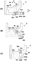
図3(A)〜図3(D)はドックプレート30の変位態様を示す図であり、ロードポート1の平面図である。本実施形態では、駆動機構34により、ドックプレート30のX方向の移動と、Z方向の軸回りの回転が可能である。
<Displacement mode of dock plate>
3 (A) to 3 (D) are views showing the displacement mode of the
図3(A)はドックプレート30がポートプレート2に対してX方向PP側に最も近接した位置(以下、ドック位置ともいう。)にある状態を示している。容器5の開閉はこのドック位置において行う。図3(B)はドックプレート30がポートプレート2から最も離間した位置(以下、受渡位置ともいう。)にある状態を示している。作業者がドックプレート30上に手作業で容器5を載置する場合、或いは、載置されている容器5を手作業で搬出する場合には、この受渡位置で行う。また、複数の容器5をストックしている容器倉庫(ストッカー)とロードポート2との間で、容器搬送ロボットを用いて、容器5の自動受渡しを行う場合についても、この受渡位置で行う。
FIG. 3A shows a state in which the
図3(C)は、ドックプレート30がドック位置と受渡位置との中間の位置(以下、中間位置ともいう。)にある状態を示している。半導体製造工場内に設置された天井搬送装置(OHT)等により、容器5を自動搬送する場合、この中間位置においてドックプレート30に対する容器5の自動載置と、載置されている容器5の自動搬出を行う。
FIG. 3C shows a state in which the
図3(D)はドックプレート30を回転させている途中の状態を示している。本実施形態では、ドックプレート30はX方向の任意の位置でZ軸を軸心に回転可能である。ドックプレート30が回転可能であることにより、例えば、受渡位置において作業者が蓋51を作業者側に向けた状態でドックプレート30に容器5を載せた後、回転ユニット83によってドックプレート30の向きを反転させ、停止させる。これにより蓋51がポートプレート2側に向いた状態となる。その後、図3(A)のドック位置にドックプレート30を移動させる。
FIG. 3D shows a state in which the
<駆動機構の構造>
駆動機構34の構造について説明する。図4はドックプレート30を透過して図示した駆動機構34の平面図である。図5は図4において支持プレート830を透過して図示した駆動機構34の平面図であり、カムプレート90と中間プレート82を見やすくするためにこれらに模様を付して強調した図である。図6は駆動機構34の底面図である。図7は、図4のVII方向矢視図であり、駆動機構34の右側面図である。
<Structure of drive mechanism>
The structure of the
駆動機構34は、ベース部7、支持ユニット8及びカム機構9を含む。ベース部7は駆動機構34の全体の支持体であり、本実施形態の場合、板状の部材である。ベース部7のY方向の中央部には、X方向に延びる長方形の貫通孔である開口部7aが設けられている。また、ベース部7の左側部には、切欠き7bが形成されており、ここにカム機構9の一部の構成が配設されている。
The
支持ユニット8は、ベース部7とドックプレート30との間に配置されている。支持ユニット8は、一対のレール部材80と、一対のレール部材80上を移動するスライダ81とを含む。Y方向に離間した各レール部材80は、それぞれX方向に延設され、ベース部7に固定されている。スライダ81は、ドックプレート30を搭載してドックプレート30と共に移動する。スライダ81の移動範囲は、ドックプレート30のX方向の移動範囲であるドック位置と受渡位置との範囲に対応している。
The
スライダ81は、中間プレート82と、回転ユニット83とを含む。中間プレート82は、レール部材80と係合し、レール部材80に沿ってスライドする複数の係合部材81a上に固定されている。中間プレート82のY方向の中央部には、貫通孔である開口部82aが形成されている。
The
回転ユニット83は、被回転体である支持プレート830を含む。ドックプレート30は支持プレート830上に搭載される。支持プレート830は、回転体834の上端部に固定されており、回転体834の回転によって回転する。これによりドックプレート30が図3(D)に例示したように回転される。回転体834は、中間プレート82に固定された軸受82bに回転自在に支持されており、中間プレート82を貫通してその下方まで延設されている。回転体834の下端部にはプーリ834aが固定されている。プーリ834aは、ベース部7の開口部7a内に位置している。
The rotating
回転ユニット83は、その駆動源として、アクチュエータ831を備える。アクチュエータ831は本実施形態の場合、ロータリシリンダであり、その出力軸にはプーリ832が固定されている。プーリ832とプーリ834aとには、無端ベルト833が巻き回されている。アクチュエータ831の駆動により、その駆動力が回転体834に伝達され、回転体834を回転させる。本実施形態では、回転ユニット83の駆動源としてロータリシリンダを例示したが、モータでもよく、また、駆動伝達機構はベルト伝動機構以外の機構であってもよい。
The
アクチュエータ831は、ブラケット835を介して中間プレート82に吊り下げられている。アクチュエータ831はベース部7の下側に位置し、ブラケット835は開口部7aを挿通してアクチュエータ831と中間プレート82とを連結している。回転ユニット83は、中間プレート82と共にX方向に移動する。
The
カム機構9は、中間プレート82をX方向に移動させる駆動機構である。カム機構9は、被移動体であるカムプレート90を含む。カムプレート90は、レール部材80に沿ってスライド自在に係合する複数の係合部材91上に固定されている。カムプレート90は中間プレート82と連結している。カムプレート90がX方向に移動することで、中間プレート82がX方向に移動する。
The
カムプレート90と中間プレート82とは、連結機構92を介して連結されている。カムプレート90と中間プレート82とはダイレクトに結合してもよいが、本実施形態の場合、カムプレート90と中間プレート82との間に弾性部材920を介在させて結合しており、弾性部材920が両者の駆動力伝達を緩衝する。すなわち、カムプレート90と中間プレート82とはX方向に相対変位が可能となっている。これにより、例えばカムプレート90が、ドック位置に向かって移動される際、ポートプレート2と容器5との間に異物が挟み込まれたとしても、弾性部材920が弾性変形することにより、作業者が負傷をしない程度の所定の値以下の荷重しか掛からない。また、このとき、容器5、カムプレート90及び中間プレート82は、これ以上、ポートプレート2に近づく方向に変位することができない。その結果、作業の安全を確保することができる。図8(A)も参照して連結機構92の構造を説明する。図8(A)は連結機構92の周辺の拡大平面図である。
The
弾性部材920はゴム等でもよいが、本実施形態ではコイルスプリングである。連結機構92は弾性部材920を挿通するロッド921を有している。ロッド921は、ブラケット922、923に設けた貫通孔を挿通している。ブラケット922は中間プレート82に固定されており、ブラケット923はカムプレート90に固定されている。ロッド921の各端部にはストッパ924が設けられている。弾性部材920はブラケット922、923が離れる方向に付勢力を発揮し、また、ブラケット922及び923は2つのストッパ924の範囲内で近接、離間が可能である。つまり、カムプレート90と中間プレート82は2つのストッパ924の範囲内で近接、離間が可能であるもの、弾性部材920の付勢で、通常時は2つのストッパ924の距離だけ離間し、何らかの外的負荷が作用したときに近接可能となっている。
The
図4〜図9(B)を参照してカム機構9について更に説明する。図8(B)は駆動機構34の部分側面視図であり、図8(A)の矢印Y1方向に見た図である。図9(A)はカムプレート90をその底面側から見た斜視図であり、図9(B)はカム機構9の駆動機構93及び検知ユニット10の斜視図である。
The
カムプレート90は、その底面にカム溝901及び902が形成されている。カム溝901及び902はX方向に離間して形成され、カム溝902がポートプレート2の側に位置している。カム溝901及び902はいずれもY方向に延設された直線状の溝であり、カム溝901の方が長い溝である。カム溝901及び902の各一端部(開端部ともいう)は、X方向に延びる溝903で接続され、各他端部(閉端部ともいう)は閉じている。
The
駆動機構93は、回転駆動ユニット930と、回転シャフト930bと、回転部材931とを含む。回転駆動ユニット930は、モータ930aを駆動し、回転シャフト930bを出力軸としたユニットであり、その内部には、モータ930aの出力を回転シャフト930bに伝達する伝達機構(歯車機構、ベルト伝動機構等)が内蔵されている。回転駆動ユニット930は、ベース部7の切り欠き7bに配置されている。切欠き7bは上側のプレート70と、下側のプレート71で部分的に塞がれ、下側のプレート71の更に下方には、回転駆動ユニット930を支持する支持プレート72が設けられている。支持プレート72は支柱73によって上側のプレート70から吊り下げられており、下側のプレート71には、支柱73や回転駆動ユニット930との干渉を避ける開口が形成されている。
The
回転シャフト930bはZ方向に延びる軸である。回転部材931は、回転シャフト930bの上端部に固定され、水平方向に延びる長片状の部材である。回転部材931は、その長手方向中心位置から長手方向一方にオフセットした位置を軸心として、回転シャフト930bに軸支される。回転部材931は回転シャフト930bを回転中心として回転される。回転部材931の長手方向の各端部には、カム溝901、902と係合するカムフォロワ932、933が回転自在に設けられている。カムフォロワ932、933の中心軸線はZ方向を指向している。
The
カムフォロワ932、933は、回転シャフト930bの周方向で異なる位置に配置されており、かつ、カムフォロワ932、933及び回転シャフト930bは水平方向において同一直線上に位置している。回転シャフト930bからカムフォロワ932、933までの距離はそれぞれ異なっており、回転シャフト930bからカムフォロワ932までの距離の方が長い。
The
カムフォロワ932、933は、本実施形態の場合、同じ直径を有しており、カム溝901とカム溝902のX方向の幅は、カムフォロワ932、933の直径よりも僅かに広い。カム溝901、902の幅方向中心線同士の離間距離は、カムフォロワ932、933の軸心同士の離間距離と等しい。
In the case of the present embodiment, the
回転部材931には、センサドグ934が設けられている。検知ユニット10はセンサドグ934を検知することで、回転部材931の回転姿勢を検知する。本実施形態の場合、検知ユニット10は、センサ11〜13までの3つのセンサで構成されている。センサ11〜13は、フォトインタラプタであり、センサドグ934が受光素子と発光素子との間に介在することを検知する。なお、回転部材931の回転姿勢は、フォトインタラプタ以外のセンサも採用可能であり、例えば、回転部材931の回転量を検知するロータリエンコーダであってもよい。
The rotating
センサ11及び12はベース部7に固定されている。センサ11は、ドックプレート30がドック位置に対応する位置に回転部材931が位置していることを検知するセンサである。この位置における回転部材931の回転角度を説明の便宜上初期位置(0度)とする。センサ12はドックプレート30が受渡位置に対応する位置に回転部材931が位置していることを検知するセンサである。この位置における回転部材931の回転角度は、平面視時計回りで略360度である。
The
センサ13は、ベース部7に対する取り付け位置が調節自在に設けられている。具体的には、センサ13はブラケット14を介してプレート70に取り付けられている。プレート70には、回転シャフト930bと同心円弧形状のスリット70a、70bが形成されている。ブラケット14はプレート70の下側に位置し、プレート70に固定して、かつ、スリット70bに挿通して設けられるボルト15に固定される。ボルト15のプレート70に対する取り付け位置はスリット70bに沿って調整自在であり、これにより、ブラケット14のプレート70に対する姿勢はスリット70bに沿って調整自在である。センサ13はブラケット14に搭載されており、スリット70aを通ってプレート70の上側に露出している。これにより、ブラケット14をスリット70bに沿って移動させることで、センサ13がスリット70aに沿って移動される。
The
センサ13は、回転部材931の位置を検知するものである。具体的には、センサ13が回転部材931を検知したとき、ドックプレート30は中間位置に位置することになる。センサ13が回転部材931を検知したとき、本実施形態の場合、回転部材931が平面視時計回りに略180度回転されたことになる(後述の図11(B)の状態)。ドックプレート30の中間位置は、天井搬送装置(OHT)等により、容器5を自動搬送する場合に利用される位置であり、この位置は天井搬送装置(OHT)及びロードポート1の設置環境に応じて調整が必要とされる場合がある。本実施形態では、センサ13の位置調節可能とすることで、このような設置環境に応じた事情に対応することができる。
The
なお、本実施形態では、センサ11、12は位置を固定としたが、センサ13と同様に調節可能としてもよい。尤も、ドック位置と受渡位置は位置の調節が必要となる場合が少なく、位置を固定することで構造を簡略化することができる。
In the present embodiment, the positions of the
<カム機構の動作>
図10(A)〜図12(C)を参照してカム機構9の動作例について説明する。これらの図は回転部材931が一回転する際の、カムプレート90の移動を図示した平面図であり、カムプレート90は透過態様で図示されている。カムプレート90は、支持ユニット8を介してドックプレート30に連結されているので、カムプレート90の移動に伴ってドックプレート30も移動することになる。
<Operation of cam mechanism>
An operation example of the
図10(A)は回転部材931の回転角度が0度の状態を示している。このとき、ドックプレート30はドック位置に位置している。回転シャフト930b、カムフォロワ932及び933はX方向の同一直線状に位置している。センサドグ934がセンサ11により検知され、この検知結果により制御部1aはドックプレート30がドック位置に位置していると認識する。カムフォロワ932はカム溝901の開端部(図10(A)中では下端部)に位置している。
FIG. 10A shows a state in which the rotation angle of the rotating
図10(B)は回転部材931が時計回りに45度回転した状態を示している。回転部材931の回転の過程でカムフォロワ932がカム溝901と係合することで、カムプレート90はポートプレート2から離れる方向側のX方向(X方向におけるPP側と反対側の方向;図10(B)中では右方向)に移動し、ドックプレート30も同様にX方向に移動する。
FIG. 10B shows a state in which the rotating
図10(C)は回転部材931が時計回りに90度回転した状態を示している。回転部材931の回転の過程でカムフォロワ932がカム溝901と係合することで、カムプレート90はポートプレート2から離れる方向側のX方向に更に移動し、ドックプレート30も同様にX方向に更に移動する。カムフォロワ932はカム溝901の閉端部(図10(C)中では上端部)に最も近い位置(折返し地点)に位置しており、カムフォロワ932が閉端部に当接することはない。回転シャフト930b、カムフォロワ932及び933はY方向の同一直線上に位置している。
FIG. 10C shows a state in which the rotating
図11(A)は回転部材931が時計回りに135度回転した状態を示している。回転部材931の回転の過程でカムフォロワ932がカム溝901の開端部の側へ移動しつつ、カムフォロワ932がカム溝901と係合することで、カムプレート90はポートプレート2から離れる方向側のX方向に更に移動し、ドックプレート30も同じ方向に更に移動する。
FIG. 11A shows a state in which the rotating
図11(B)は回転部材931が時計回りに180度回転した状態を示している。回転部材931の回転の過程でカムフォロワ932がカム溝901と係合することで、カムプレート90はポートプレート2から離れる方向側のX方向に更に移動し、ドックプレート30も同じ方向に更に移動して中間位置に到達する。カムフォロワ932はカム溝901の開端部に位置し、カムフォロワ933はカム溝902の開端部(図11(B)中では下端部)に位置している。回転シャフト930b、カムフォロワ932及び933はX方向の同一直線上に位置しているが、図10(A)の状態とカムフォロワ932、933の位置が逆になっている。センサドグ934がセンサ13により検知され、この検知結果により制御部1aはドックプレート30が中間位置に位置していると認識する。
FIG. 11B shows a state in which the rotating
図11(C)は回転部材931が時計回りに225度回転した状態を示している。回転部材931の回転の過程でカムフォロワ933がカム溝902の開端部の側へ移動しつつ、カムフォロワ933がカム溝902と係合することで、カムプレート90はポートプレート2から離れる方向側のX方向に更に移動し、ドックプレート30も同じ方向に更に移動する。
FIG. 11C shows a state in which the rotating
図12(A)は回転部材931が時計回りに270度回転した状態を示している。回転部材931の回転の過程でカムフォロワ933がカム溝902と係合することで、カムプレート90はポートプレート2から離れる方向側のX方向に更に移動し、ドックプレート30も同じ方向に更に移動する。カムフォロワ933はカム溝902の閉端部に最も近い位置(折返し地点)に位置している。回転シャフト930b、カムフォロワ932及び933はY方向の同一直線上に位置しているが、図10(C)の状態とカムフォロワ932、933の位置が逆になっている。
FIG. 12A shows a state in which the rotating
図12(B)は回転部材931が時計回りに315度回転した状態を示している。回転部材931の回転の過程でカムフォロワ933がカム溝902の開端部の側へ移動しつつ、カムフォロワ933がカム溝902と係合することで、カムプレート90はポートプレート2から離れる方向側のX方向に更に移動し、ドックプレート30も同じ方向に更に移動する。
FIG. 12B shows a state in which the rotating
図12(C)は回転部材931が時計回りに略360度回転した状態を示している。回転部材931の回転の過程でカムフォロワ933がカム溝902と係合することで、カムプレート90はポートプレート2から離れる方向側のX方向に更に移動し、ドックプレート30も同じ方向に更に移動して受渡位置に到達する。カムフォロワ933はカム溝902の開端部に位置している。回転シャフト930b、カムフォロワ932及び933はX方向の略同一直線上に位置しているが、図10(A)の状態とは同じ状態ではなく、センサ11とセンサ12の取付位置の違いにより、実際には、360度よりも僅かに手前の位置で回転が停止している。センサドグ934がセンサ12により検知され、この検知結果により制御部1aはドックプレート30が受渡位置に位置していると認識する。
FIG. 12C shows a state in which the rotating
本実施形態では、センサ11とセンサ12を別々に設けたが、センサ11のみを設置し、センサ11によりドック位置と受渡位置の両方を検知するようにしてもよい。その場合には、図10(A)の状態と図12(C)の状態は同じ状態となる。
In the present embodiment, the
ドックプレート30を受渡位置から中間位置、中間位置からドック位置へ移動させる場合、回転部材931を反時計回りに回転させることになる。
When the
以上のように、本実施形態では、回転部材931の一回転によって、ドックプレート30をドック位置と受渡し位置との間で移動することができる。また、回転部材931の半回転によって、ドックプレート30をドック位置と中間位置との間、又は、中間位置と受渡し位置との間で移動させることができる。回転部材931の回転と、二組のカム溝、カムフォロワの組み合わせを利用したことで、ドックプレート30の移動ストローク全長に渡って、駆動源となるアクチュエータを延設する必要がなく、比較的コンパクトな機構で、ドックプレート30を移動可能なロードポート1を提供することができる。また、中間位置は、回転部材931の回転量とセンサ13の位置調節によって、任意の位置に設定することができ、また、ドックプレート30の回転も可能である。よって、本実施形態のロードポート1は、容器倉庫(ストッカー)、天井搬送装置(OHT)等の設置環境や運用状況に左右されることなく、設置、使用することができる。
As described above, in the present embodiment, the
また、ドックプレート30の停止位置の種類に対応した複数の制御モードを作業者が選択可能とすることで、更に柔軟な使用が可能となる。複数の制御モードは、ドックプレート30の停止位置として、受渡位置を使用しない第1の制御モードを含むことができる。この第1の制御モードの場合、ドックプレート30の停止位置は、ドック位置と中間位置の2か所である。また、ドックプレート30の停止位置として、中間位置を使用しない第2の制御モードを含むことができる。この第2の制御モードの場合、ドックプレート30の停止位置は、ドック位置と受渡位置の2か所である。また、ドックプレート30の停止位置として、ドック位置、中間位置、受渡位置の3か所全てを使用する第3の制御モードを含むことができる。これらの第1〜第3の制御モードでは、更に、ドックプレート30を回転させるか否かが異なる制御モードも含むことができる。
Further, by allowing the operator to select a plurality of control modes corresponding to the type of stop position of the
具体的には、ドックプレート30の停止位置としてドック位置と中間位置の2ヶ所のみ使用する第1の制御モードの場合には、ドックプレート30は回転させない制御モードのみを含み、回転させる場合の制御モードは含まない。
Specifically, in the case of the first control mode in which only two positions, the dock position and the intermediate position, are used as the stop positions of the
ドックプレート30の停止位置として、中間位置を使用しない第2の制御モードの場合には、容器5を載置した状態でドックプレート30を回転させた際に容器5とポートプレート2との間で干渉が生じる領域を除く任意の位置でドックプレート30を回転させる場合と、ドックプレート30を回転させない場合の制御モードを含む。任意の位置は、言い換えると、ドックプレート30を回転させた際に容器5とポートプレート2との間で干渉が生じない領域における任意の一点であり、受渡位置を含んでもよい。
In the case of the second control mode in which the intermediate position is not used as the stop position of the
ドックプレート30の停止位置として、ドック位置、中間位置、受渡位置の3か所全てを使用する第3の制御モードの場合には、中間位置において、容器5を載置した状態で回転させると、容器5とポートプレート2との間で干渉が生じるので、中間位置よりも受渡位置寄りでかつ干渉が生じない領域における任意の位置でドックプレート30を回転させる場合と、ドックプレート30を回転させない場合の制御モードを含む。任意の位置は、受渡位置であってもよい。
In the case of the third control mode in which all three positions of the dock position, the intermediate position, and the delivery position are used as the stop positions of the
図13(A)はこうした制御モードの選択を受け付ける処理の例を示すフローチャートであり、制御部1aが実行する処理の例である。S1では予め定められた複数の制御モードの中から、作業者による制御モードの選択を受け付ける。制御モードの選択は、操作パネル33による入力、又は、通信回線1bを介して制御部1aと通信可能なホストコンピュータ等からの入力、によって受け付けられる。S2ではS1での選択内容を保存し、制御モードを設定する。以降、設定された制御モードで制御部1aはロードポート1を動作させる。
FIG. 13A is a flowchart showing an example of a process of accepting the selection of such a control mode, and is an example of a process executed by the
図13(B)は制御モードが設定された後、ロードポート1の動作を制御部1aが制御する場合の処理の例を示すフローチャートであり、特に、ドックプレート30の移動制御例を示している。S11ではドックプレート30の移動指示を受け付ける。移動指示は操作パネル33による作業者の手動入力、又は、システムの自動制御中に、通信回線1bを介して制御部1aと通信可能なホストコンピュータ等からの制御指示入力、によって受け付けられる。
FIG. 13B is a flowchart showing an example of processing when the
S12ではS11で受け付けた移動指示を、設定中の制御モードにしたがって実行する。例えば、ドックプレート30の停止位置として、受渡位置を使用しない第1の制御モードが設定されている場合、移動指示がある度に、回転方向を切り替えながら回転部材931を半回転させる。これにより、移動指示がある度にドックプレート30はドック位置から中間位置へ、また、中間位置からドック位置へ、移動する。回転部材931の回転範囲は半回転である。
In S12, the movement instruction received in S11 is executed according to the control mode being set. For example, when the first control mode that does not use the delivery position is set as the stop position of the
また、例えば、ドックプレート30の停止位置として、中間位置を使用しない第2の制御モードが設定されている場合、移動指示がある度に、回転方向を切り替えながら回転部材931を一回転させる。これにより、移動指示がある度にドックプレート30はドック位置から受渡位置へ、また、受渡位置からドック位置へ、移動する。回転部材931の回転範囲は一回転である。
Further, for example, when a second control mode that does not use the intermediate position is set as the stop position of the
また、例えば、ドックプレート30の停止位置として、ドック位置、中間位置、受渡位置の3か所全てを使用する第3の制御モードが設定されている場合、移動指示がある度に、回転部材931を半回転させる。回転方向は2回の移動指示毎に切り替える。これにより、移動指示がある度にドックプレート30はドック位置から中間位置へ、また、中間位置から受渡位置へ、受渡位置から中間位置へ、中間位置からドック位置へ、移動する。回転部材931の回転範囲は一回転である。
Further, for example, when a third control mode using all three positions of the dock position, the intermediate position, and the delivery position is set as the stop position of the
<第二実施形態>
ブラケット14を用いたセンサ13の取付構造に代えて、センサ13の位置を自動変更するセンサ移動機構を設けてもよい。図14はその一例を示す、駆動機構34の部分側面視図であり、図8(A)の矢印Y1方向に見た図(図8(B)に相当する)である。
<Second embodiment>
Instead of the mounting structure of the
センサ移動機構16は、駆動源であるモータ16aと、モータ16aの出力軸に固定されて回動するアーム部材16bとを含み、センサ13はアーム部材16bに搭載される。モータ16aは不図示のブラケットによりベース部7に支持される。センサ移動機構16の配置スペースを確保するため、回転駆動ユニット930の配置等が第一実施形態と異なっている。
The
モータ16aの出力軸の中心線16cは、回転シャフト930bと同軸線上に位置し、アーム部材16bは中心線16c回りに回動する。アーム部材16bの回動によって、センサ13をスリット70a内で、回転シャフト930bの周方向に移動することができ、その検知位置を変更できる。駆動部1aは、操作パネル33に対する作業者の操作に応じてモータ16aの回転制御を行う。ブラケット14を用いたセンサ13の位置調節に対して、センサ13の位置調節を自動化できる。
The
以上、発明の実施形態について説明したが、発明は上記の実施形態に制限されるものではなく、発明の要旨の範囲内で、種々の変形・変更が可能である。 Although the embodiments of the invention have been described above, the invention is not limited to the above-described embodiments, and various modifications and changes can be made within the scope of the gist of the invention.
1 ロードポート、2 ポートプレート、3 載置台、8 支持ユニット、9 カム機構、30 ドックプレート、90 カムプレート、93 駆動機構 1 load port, 2 port plate, 3 mount, 8 support unit, 9 cam mechanism, 30 dock plate, 90 cam plate, 93 drive mechanism
Claims (13)
前記基板が収容される容器が載置される載置台と、
を備えたロードポートであって、
前記載置台は、
ベース部と、
前記容器が載置されるドックプレートと、
前記ベース部と前記ドックプレートとの間に設けられ、前記ドックプレートを前記ポートプレート側の第一の位置と、前記ポートプレートから離間した第二の位置との間で移動可能に支持する支持ユニットと、
前記ドックプレートを前記ベース部に対して前記第一の位置と前記第二の位置との間で移動させるカム機構と、を備え、
前記支持ユニットは、前記ドックプレートが搭載され、前記ドックプレートと共に移動するスライダを含み、
前記カム機構は、
前記ベース部に設けられた駆動機構と、
前記スライダに連結され、カム溝が形成されたカムプレートと、を含み、
前記駆動機構は、
回転駆動ユニットと、
該回転駆動ユニットにより回転される回転シャフトと、
該回転シャフトに固定され、該回転シャフトを回転中心として回転する長片状の回転部材と、
前記回転部材に設けられた第一のカムフォロワ及び第二のカムフォロワと、を含み、
前記カム溝は、
前記第一のカムフォロワと係合する第一のカム溝と、
前記ドックプレートの移動方向で前記第一のカム溝と異なる位置に形成され、前記第二のカムフォロワと係合する第二のカム溝と、を含む、
ことを特徴とするロードポート。 A port plate with an opening that allows the board to be taken in and out,
A mounting table on which the container in which the substrate is housed is placed, and
It is a load port equipped with
The above-mentioned stand is
With the base part
The dock plate on which the container is placed and
A support unit provided between the base portion and the dock plate and movably supporting the dock plate between a first position on the port plate side and a second position separated from the port plate. When,
A cam mechanism for moving the dock plate between the first position and the second position with respect to the base portion is provided.
The support unit includes a slider on which the dock plate is mounted and moves with the dock plate.
The cam mechanism
The drive mechanism provided on the base and
Includes a cam plate connected to the slider and formed with a cam groove.
The drive mechanism is
Rotation drive unit and
A rotating shaft rotated by the rotary drive unit and
A long piece-shaped rotating member fixed to the rotating shaft and rotating around the rotating shaft,
A first cam follower and a second cam follower provided on the rotating member are included.
The cam groove is
A first cam groove that engages with the first cam follower,
A second cam groove formed at a position different from the first cam groove in the moving direction of the dock plate and engaging with the second cam follower.
A load port that features that.
前記スライダは、
前記カムプレートと連結され、前記カム機構により移動される中間プレートと、
該中間プレートに設けられ、前記ドックプレートを回転可能に支持する回転ユニットと、を備える、
ことを特徴とするロードポート。 The load port according to claim 1.
The slider
An intermediate plate that is connected to the cam plate and moved by the cam mechanism,
A rotating unit provided on the intermediate plate and rotatably supporting the dock plate is provided.
A load port that features that.
前記カムプレートと前記中間プレートとの間に、弾性部材が介在している、
ことを特徴とするロードポート。 The load port according to claim 2.
An elastic member is interposed between the cam plate and the intermediate plate.
A load port that features that.
前記ベース部に設けられ、前記回転部材の回転姿勢を検知する検知手段を更に備える、
ことを特徴とするロードポート。 The load port according to any one of claims 1 to 3.
Further provided on the base portion is a detecting means for detecting the rotational posture of the rotating member.
A load port that features that.
前記検知手段は、
前記ドックプレートが前記第一の位置、前記第二の位置または前記第一の位置と前記第二の位置との間の中間位置にあるときの、前記回転部材の回転姿勢を検知する、
ことを特徴とするロードポート。 The load port according to claim 4.
The detection means
Detects the rotational posture of the rotating member when the dock plate is at the first position, the second position, or an intermediate position between the first position and the second position.
A load port that features that.
前記検知手段は、前記第一の位置、前記第二の位置および前記中間位置に対応して設けられた第一乃至第三のセンサを含み、
該中間位置に対応して設けられた前記第三のセンサは、前記ベース部に対する位置が調節自在である、
ことを特徴とするロードポート。 The load port according to claim 5.
The detection means includes first to third sensors provided corresponding to the first position, the second position and the intermediate position.
The position of the third sensor provided corresponding to the intermediate position is adjustable with respect to the base portion.
A load port that features that.
駆動源を含み、該駆動源の駆動力により前記中間位置に対応して設けられた前記第三のセンサの位置を前記回転シャフトの周方向に変更するセンサ移動機構を備える、
ことを特徴とするロードポート。 The load port according to claim 6.
A sensor moving mechanism including a drive source and changing the position of the third sensor provided corresponding to the intermediate position in the circumferential direction of the rotating shaft by the driving force of the drive source is provided.
A load port that features that.
前記第一のカムフォロワ及び前記第二のカムフォロワは、前記回転シャフトの周方向で異なる位置に配置され、かつ、前記回転シャフトまでの距離が互いに異なる、
ことを特徴とするロードポート。 The load port according to any one of claims 1 to 7.
The first cam follower and the second cam follower are arranged at different positions in the circumferential direction of the rotating shaft, and the distances to the rotating shaft are different from each other.
A load port that features that.
前記第一のカム溝及び前記第二のカム溝は、前記ドックプレートの移動方向と直交する方向に延びる直線状の溝であり、
前記回転シャフトと、前記第一のカムフォロワと、前記第二のカムフォロワとは同一の直線上に位置し、
該同一の直線が前記ドックプレートの移動方向と平行となるとき、前記ドックプレートは前記第一の位置または前記第二の位置に位置する、
ことを特徴とするロードポート。 The load port according to any one of claims 1 to 7.
The first cam groove and the second cam groove are linear grooves extending in a direction orthogonal to the moving direction of the dock plate.
The rotating shaft, the first cam follower, and the second cam follower are located on the same straight line.
When the same straight line is parallel to the moving direction of the dock plate, the dock plate is located at the first position or the second position.
A load port that features that.
前記回転部材が初期位置から半回転する間に、前記第一のカムフォロワと前記第一のカム溝との係合によって、前記ドックプレートが前記第一の位置と前記第二の位置との間の中間位置まで移動し、
前記回転部材が半回転した位置から一回転する間に、前記第二のカムフォロワと前記第二のカム溝との係合によって、前記ドックプレートが前記中間位置から前記第二の位置まで移動し、
前記回転部材の回転範囲が前記初期位置から半回転するまでとなる第一の制御モードと、前記回転部材の回転範囲が前記初期位置から一回転するまでとなる第二の制御モードと、選択可能である、
ことを特徴とするロードポート。 The load port according to claim 1.
While the rotating member makes a half turn from the initial position, the dock plate is placed between the first position and the second position by the engagement between the first cam follower and the first cam groove. Move to the middle position,
While the rotating member makes one rotation from the half-turned position, the dock plate moves from the intermediate position to the second position due to the engagement between the second cam follower and the second cam groove.
A first control mode in which the rotation range of the rotating member is rotated half a turn from the initial position and a second control mode in which the rotation range of the rotating member is rotated once from the initial position can be selected. Is,
A load port that features that.
前記回転部材の回転範囲が前記初期位置から一回転するまでとなる第三の制御モードを選択可能であり、前記第三の制御モードは、前記回転部材が半回転する度に前記回転部材の回転を停止する、
ことを特徴とするロードポート。 The load port according to claim 10.
A third control mode in which the rotation range of the rotating member is from the initial position to one rotation can be selected, and in the third control mode, the rotation of the rotating member is rotated every half rotation of the rotating member. To stop
A load port that features that.
前記回転部材が初期位置から半回転する間に、前記第一のカムフォロワと前記第一のカム溝との係合によって、前記ドックプレートが前記第一の位置と前記第二の位置との間の中間位置まで移動し、
前記回転部材が半回転した位置から一回転する間に、前記第二のカムフォロワと前記第二のカム溝との係合によって、前記ドックプレートが前記中間位置から前記第二の位置まで移動し、
前記制御方法は、
第一の制御モード又は第二の制御モードの選択を受け付ける設定工程と、
前記回転部材を回転させ、前記ドックプレートを移動させる制御工程と、を含み、
前記制御工程では、前記第一の制御モードが設定された場合には、前記回転部材を前記初期位置から半回転するまでの回転範囲内で回転させ、前記第二の制御モードが設定された場合には、前記回転部材を前記初期位置から一回転するまでの回転範囲内で回転させる、
ことを特徴とする制御方法。 The load port control method according to claim 1.
While the rotating member makes a half turn from the initial position, the dock plate is placed between the first position and the second position by the engagement between the first cam follower and the first cam groove. Move to the middle position,
While the rotating member makes one rotation from the half-turned position, the dock plate moves from the intermediate position to the second position due to the engagement between the second cam follower and the second cam groove.
The control method is
A setting process that accepts the selection of the first control mode or the second control mode,
A control step of rotating the rotating member and moving the dock plate, and the like.
In the control step, when the first control mode is set, the rotating member is rotated within a rotation range from the initial position to half a rotation, and the second control mode is set. The rotating member is rotated within the rotation range from the initial position to one rotation.
A control method characterized by that.
前記設定工程では、第三の制御モードの選択を受け付け可能であり、
前記制御工程では、前記第三の制御モードが設定された場合には、前記回転部材を前記初期位置から一回転するまでの回転範囲内で回転させ、かつ、記回転部材が半回転する度に前記回転部材の回転を停止する、
ことを特徴とする制御方法。 The control method according to claim 12.
In the setting process, it is possible to accept the selection of the third control mode.
In the control step, when the third control mode is set, the rotating member is rotated within the rotation range from the initial position to one rotation, and each time the rotating member rotates half a turn. Stop the rotation of the rotating member,
A control method characterized by that.
Priority Applications (5)
| Application Number | Priority Date | Filing Date | Title |
|---|---|---|---|
| JP2019063990A JP6856692B2 (en) | 2019-03-28 | 2019-03-28 | Load port |
| TW109107212A TWI730653B (en) | 2019-03-28 | 2020-03-05 | Load port |
| KR1020200030818A KR102295675B1 (en) | 2019-03-28 | 2020-03-12 | Load port |
| CN202010201084.0A CN111755369B (en) | 2019-03-28 | 2020-03-20 | Load port |
| US16/827,801 US11069550B2 (en) | 2019-03-28 | 2020-03-24 | Load port |
Applications Claiming Priority (1)
| Application Number | Priority Date | Filing Date | Title |
|---|---|---|---|
| JP2019063990A JP6856692B2 (en) | 2019-03-28 | 2019-03-28 | Load port |
Publications (2)
| Publication Number | Publication Date |
|---|---|
| JP2020167193A JP2020167193A (en) | 2020-10-08 |
| JP6856692B2 true JP6856692B2 (en) | 2021-04-07 |
Family
ID=72604816
Family Applications (1)
| Application Number | Title | Priority Date | Filing Date |
|---|---|---|---|
| JP2019063990A Active JP6856692B2 (en) | 2019-03-28 | 2019-03-28 | Load port |
Country Status (5)
| Country | Link |
|---|---|
| US (1) | US11069550B2 (en) |
| JP (1) | JP6856692B2 (en) |
| KR (1) | KR102295675B1 (en) |
| CN (1) | CN111755369B (en) |
| TW (1) | TWI730653B (en) |
Families Citing this family (1)
| Publication number | Priority date | Publication date | Assignee | Title |
|---|---|---|---|---|
| KR20230037990A (en) * | 2021-09-10 | 2023-03-17 | 삼성전자주식회사 | Wafer processing device comprising efem and method for processing wafer |
Family Cites Families (27)
| Publication number | Priority date | Publication date | Assignee | Title |
|---|---|---|---|---|
| JPS6038476B2 (en) | 1977-05-21 | 1985-08-31 | 株式会社トクヤマ | How to disconnect the battery case |
| JPS61217415A (en) * | 1985-03-23 | 1986-09-27 | Sony Corp | Cassette stocker |
| JPH07240454A (en) * | 1994-03-01 | 1995-09-12 | Kiyoshi Takahashi | Wafer transfer apparatus |
| US6799932B2 (en) * | 1994-04-28 | 2004-10-05 | Semitool, Inc. | Semiconductor wafer processing apparatus |
| US6281516B1 (en) * | 1998-07-13 | 2001-08-28 | Newport Corporation | FIMS transport box load interface |
| US7021882B2 (en) * | 2000-11-30 | 2006-04-04 | Hirata Corporation | Drive-section-isolated FOUP opener |
| JP2002184831A (en) * | 2000-12-11 | 2002-06-28 | Hirata Corp | Foup opener |
| JP2004047839A (en) * | 2002-07-15 | 2004-02-12 | Hirata Corp | Sealed container opening/closing device |
| JP2004311864A (en) * | 2003-04-10 | 2004-11-04 | Tdk Corp | Load port for semiconductor processing equipment |
| JP3917100B2 (en) * | 2003-04-10 | 2007-05-23 | Tdk株式会社 | Opening and closing mechanism for substrate processing equipment |
| JP2005272041A (en) * | 2004-03-23 | 2005-10-06 | Pentax Corp | Conveying mechanism of substrate |
| JP4526535B2 (en) | 2004-06-14 | 2010-08-18 | 平田機工株式会社 | Container opening and closing device |
| JP4891538B2 (en) * | 2004-11-04 | 2012-03-07 | 株式会社日立ハイテクノロジーズ | Load port |
| KR101087239B1 (en) * | 2004-12-09 | 2011-11-29 | 엘지디스플레이 주식회사 | Mobile buffer and loading system with it |
| JP4597708B2 (en) * | 2005-02-25 | 2010-12-15 | 平田機工株式会社 | FOUP opener |
| US20090053019A1 (en) * | 2005-03-08 | 2009-02-26 | Kabushiki Kaisha Yaskawa Denki | Load port and load port control method |
| US8821099B2 (en) | 2005-07-11 | 2014-09-02 | Brooks Automation, Inc. | Load port module |
| KR100707881B1 (en) * | 2005-09-23 | 2007-04-13 | 삼성전자주식회사 | System and method for transferring substrates and method for aligning substrates |
| JP4856420B2 (en) * | 2005-12-06 | 2012-01-18 | 株式会社ライト製作所 | Load port |
| US8128333B2 (en) * | 2006-11-27 | 2012-03-06 | Hitachi Kokusai Electric Inc. | Substrate processing apparatus and manufacturing method for semiconductor devices |
| JP5212165B2 (en) * | 2009-02-20 | 2013-06-19 | 東京エレクトロン株式会社 | Substrate processing equipment |
| JP5518513B2 (en) * | 2010-02-04 | 2014-06-11 | 平田機工株式会社 | Hoop opener and operation method thereof |
| JP6038476B2 (en) | 2012-04-07 | 2016-12-07 | 平田機工株式会社 | Carrier loading / unloading device and loading / unloading method |
| JP5978728B2 (en) * | 2012-04-12 | 2016-08-24 | 東京エレクトロン株式会社 | Substrate delivery apparatus, substrate delivery method and storage medium |
| JP5920627B2 (en) * | 2012-08-29 | 2016-05-18 | Tdk株式会社 | Load port device |
| JP6260109B2 (en) * | 2013-05-16 | 2018-01-17 | シンフォニアテクノロジー株式会社 | Load port device |
| JP6882656B2 (en) * | 2016-07-08 | 2021-06-02 | シンフォニアテクノロジー株式会社 | Board transfer system with load port and load port |
-
2019
- 2019-03-28 JP JP2019063990A patent/JP6856692B2/en active Active
-
2020
- 2020-03-05 TW TW109107212A patent/TWI730653B/en active
- 2020-03-12 KR KR1020200030818A patent/KR102295675B1/en active Active
- 2020-03-20 CN CN202010201084.0A patent/CN111755369B/en active Active
- 2020-03-24 US US16/827,801 patent/US11069550B2/en active Active
Also Published As
| Publication number | Publication date |
|---|---|
| KR20200115149A (en) | 2020-10-07 |
| US20200312690A1 (en) | 2020-10-01 |
| TWI730653B (en) | 2021-06-11 |
| US11069550B2 (en) | 2021-07-20 |
| TW202101652A (en) | 2021-01-01 |
| KR102295675B1 (en) | 2021-08-30 |
| CN111755369B (en) | 2023-05-16 |
| JP2020167193A (en) | 2020-10-08 |
| CN111755369A (en) | 2020-10-09 |
Similar Documents
| Publication | Publication Date | Title |
|---|---|---|
| US11094570B2 (en) | Load port having movable member that abuts a pin | |
| US20140109400A1 (en) | Container opening/closing device | |
| KR101952767B1 (en) | Robot | |
| US8668423B2 (en) | Grasping device, robot system, and method of manufacturing mechanical product | |
| KR102165982B1 (en) | Lid closure system and lid closure method | |
| US10087019B2 (en) | Load lock system and method for transferring substrates in a lithography system | |
| JP2019136834A (en) | Connection device and connection method | |
| JP6856692B2 (en) | Load port | |
| TWI517951B (en) | Robot system | |
| KR20180059255A (en) | Gripper of transfer apparatus for semiconductor wafer | |
| KR20190050482A (en) | Mapping apparatus for load port that detects the presence or position of wafer | |
| TWI442493B (en) | Processing device | |
| US20110218663A1 (en) | Pre-aligner apparatus | |
| JP2006222190A (en) | Wafer aligner | |
| KR20190099127A (en) | Method of calculating correction value of industrial robot | |
| JP6853396B2 (en) | Load port | |
| JP6242119B2 (en) | Exposure apparatus having a wide-angle rotation mechanism | |
| KR20130124986A (en) | Orientation adjustment device, and orientation adjustment method | |
| JP6751636B2 (en) | Alignment device, semiconductor wafer processing device equipped with the alignment device, and alignment method | |
| KR101973146B1 (en) | Wafer aligning apparatus | |
| JPH05269689A (en) | Work holding device | |
| JP4253945B2 (en) | Robot hand tilt mechanism | |
| JP7152013B2 (en) | Grasping device, robot arm and opening expansion/contraction mechanism | |
| NL2015784B1 (en) | Load lock system and method for transferring substrates in a lithography system. | |
| KR200353729Y1 (en) | semiconductor feed mechanism |
Legal Events
| Date | Code | Title | Description |
|---|---|---|---|
| A521 | Request for written amendment filed |
Free format text: JAPANESE INTERMEDIATE CODE: A523 Effective date: 20200309 |
|
| A621 | Written request for application examination |
Free format text: JAPANESE INTERMEDIATE CODE: A621 Effective date: 20200309 |
|
| RD02 | Notification of acceptance of power of attorney |
Free format text: JAPANESE INTERMEDIATE CODE: A7422 Effective date: 20210122 |
|
| A977 | Report on retrieval |
Free format text: JAPANESE INTERMEDIATE CODE: A971007 Effective date: 20210225 |
|
| TRDD | Decision of grant or rejection written | ||
| A01 | Written decision to grant a patent or to grant a registration (utility model) |
Free format text: JAPANESE INTERMEDIATE CODE: A01 Effective date: 20210308 |
|
| A61 | First payment of annual fees (during grant procedure) |
Free format text: JAPANESE INTERMEDIATE CODE: A61 Effective date: 20210318 |
|
| R150 | Certificate of patent or registration of utility model |
Ref document number: 6856692 Country of ref document: JP Free format text: JAPANESE INTERMEDIATE CODE: R150 |
|
| R250 | Receipt of annual fees |
Free format text: JAPANESE INTERMEDIATE CODE: R250 |