JP6849753B2 - Cartridge and image forming device using it - Google Patents
Cartridge and image forming device using it Download PDFInfo
- Publication number
- JP6849753B2 JP6849753B2 JP2019140309A JP2019140309A JP6849753B2 JP 6849753 B2 JP6849753 B2 JP 6849753B2 JP 2019140309 A JP2019140309 A JP 2019140309A JP 2019140309 A JP2019140309 A JP 2019140309A JP 6849753 B2 JP6849753 B2 JP 6849753B2
- Authority
- JP
- Japan
- Prior art keywords
- cartridge
- main body
- storage medium
- unit
- bearing portion
- Prior art date
- Legal status (The legal status is an assumption and is not a legal conclusion. Google has not performed a legal analysis and makes no representation as to the accuracy of the status listed.)
- Active
Links
Images


Landscapes
- Electrophotography Configuration And Component (AREA)
Description
本発明は、カートリッジおよびこれを用いた画像形成装置に関し、電子写真複写機、電子写真プリンタ(LEDプリンタ、レーザビームプリンタ等)、ファクシミリ装置及びワードプロセッサ等に好適なものである。 The present invention relates to a cartridge and an image forming apparatus using the same, and is suitable for an electrophotographic copying machine, an electrophotographic printer (LED printer, laser beam printer, etc.), a facsimile machine, a word processor, and the like.
画像形成装置では、像担持体としての一般にドラム型とされる電子写真感光体、即ち、感光体ドラムを一様に帯電させる。次いで、帯電した感光体ドラムを選択的に露光することによって、感光体ドラム上に静電潜像(静電像)を形成する。次いで、感光体ドラム上に形成された静電潜像を、現像剤としてのトナーでトナー像として現像する。そして、感光体ドラム上に形成されたトナー像を、記録用紙、プラスチックシートなどの記録材に転写し、更に記録材上に転写されたトナー像に熱や圧力を加えることでトナー像を記録材に定着させることで画像記録を行う。 In the image forming apparatus, an electrophotographic photosensitive member, which is generally a drum type as an image carrier, that is, a photosensitive member drum is uniformly charged. Next, an electrostatic latent image (electrostatic image) is formed on the photoconductor drum by selectively exposing the charged photoconductor drum. Next, the electrostatic latent image formed on the photoconductor drum is developed as a toner image with toner as a developer. Then, the toner image formed on the photoconductor drum is transferred to a recording material such as recording paper or a plastic sheet, and heat or pressure is applied to the toner image transferred on the recording material to record the toner image. Image recording is performed by fixing to.
このような画像形成装置は、一般に、トナー補給や各種のプロセス手段のメンテナンスを必要とする。このトナー補給やメンテナンスを容易にするために、感光体ドラム、帯電手段、現像手段、クリーニング手段などを枠体内にまとめてカートリッジ化し、画像形成装置本体に着脱可能なプロセスカートリッジとしたものが実用化されている。 Such an image forming apparatus generally requires toner replenishment and maintenance of various process means. In order to facilitate this toner replenishment and maintenance, a photoconductor drum, charging means, developing means, cleaning means, etc. are collectively made into a cartridge in the frame, and a process cartridge that can be attached to and detached from the image forming apparatus main body is put into practical use. Has been done.
ここで、プロセスカートリッジとは、電子写真感光体ドラムなどの像担持体を少なくとも備える、更には像担持体と、像担持体に作用するプロセス手段とを一体的に備えるカートリッジである。このようなプロセスカートリッジは、画像形成装置の装置本体に対して取り外し可能に装着されるものである。 Here, the process cartridge is a cartridge that includes at least an image carrier such as an electrophotographic photosensitive member drum, and further integrally includes an image carrier and a process means that acts on the image carrier. Such a process cartridge is detachably attached to the main body of the image forming apparatus.
このプロセスカートリッジ方式によれば、装置のメンテナンスをユーザ自身で行うことができるので、格段に操作性を向上させることができ、ユーザビリティーに優れた画像形成装置を提供することができる。そのため、このプロセスカートリッジ方式は画像形成装置において広く用いられている。 According to this process cartridge method, since the maintenance of the device can be performed by the user himself / herself, the operability can be remarkably improved, and the image forming device having excellent usability can be provided. Therefore, this process cartridge method is widely used in an image forming apparatus.
また、上述したプロセスカートリッジには、様々なサービス情報やプロセス情報を記憶する記憶媒体を搭載したものがある。画像形成装置はこの記憶媒体の情報を活用することにより、画質やプロセスカートリッジのメンテナンスをより一層向上させている。 Further, some of the above-mentioned process cartridges are equipped with a storage medium for storing various service information and process information. By utilizing the information in this storage medium, the image forming apparatus further improves the image quality and the maintenance of the process cartridge.
このような、記憶媒体と画像形成装置本体の安定した電気的接続のために、記憶媒体と画像形成装置本体の相互の位置決めを行っているものが知られる(特許文献1、2、3)。
For such a stable electrical connection between the storage medium and the image forming apparatus main body, there are known ones in which the storage medium and the image forming apparatus main body are positioned with each other (
ここで、記憶媒体と画像形成装置本体の安定した電気的接続のために、記憶媒体と画像形成装置本体の相互の位置決めを特別なスペースを設けることなくできることが望まれている。 Here, for stable electrical connection between the storage medium and the image forming apparatus main body, it is desired that the storage medium and the image forming apparatus main body can be positioned with each other without providing a special space.
本発明の目的は、記憶媒体と画像形成装置本体の安定した電気的接続のために、記憶媒体と画像形成装置本体の相互の位置決めを特別なスペースを設けることなくできるカートリッジおよびこれを用いた画像形成装置を提供することにある。 An object of the present invention is a cartridge capable of mutually positioning the storage medium and the image forming apparatus main body without providing a special space for stable electrical connection between the storage medium and the image forming apparatus main body, and an image using the cartridge. The purpose is to provide a forming device.
本発明の一態様は、像担持体を支持する第1の軸受部を備える第1のユニットと、前記像担持体に形成された静電潜像を現像剤で現像する現像剤担持体を支持する第2の軸受部を備える第2のユニットと、前記第2のユニットに支持され、電気接点面を備える記憶媒体と、を有し、画像形成装置の装置本体に対し挿入可能なカートリッジであって、前記像担持体の回転軸線方向において、前記第2の軸受部は前記第1の軸受部の内側に設けられ、前記記憶媒体の少なくとも一部は、前記回転軸線方向において、前記第2の軸受部より外側で、かつ前記第1のユニットの最外形より内側となる位置に設けられ、前記電気接点面は、前記カートリッジの下部に配置され、更に、前記回転軸線方向に交差する方向を向き、前記カートリッジの前記装置本体への挿入方向に対して傾斜しており、前記装置本体の本体接点に接続される際に前記装置本体の本体接点に対向するように配置されていることを特徴とするカートリッジである。 One aspect of the present invention supports a first unit including a first bearing portion that supports the image carrier, and a developer carrier that develops an electrostatic latent image formed on the image carrier with a developer. A cartridge having a second unit provided with a second bearing portion and a storage medium supported by the second unit and provided with an electrical contact surface, which can be inserted into the main body of the image forming apparatus. Te, the rotational axis direction of the image bearing member, said second bearing portion provided on the inner side of the first bearing portion, at least a portion of the storage medium, before Symbol rotational axis direction, the second It is provided at a position outside the bearing portion of the above and inside the outermost shape of the first unit, and the electrical contact surface is arranged at the lower part of the cartridge, and further, a direction intersecting the rotation axis direction. The cartridge is oriented and inclined with respect to the insertion direction of the cartridge into the main body of the device, and is arranged so as to face the main body contact of the device main body when connected to the main body contact of the device main body. It is a cartridge to be.
また、本発明に係る画像形成装置は、上記カートリッジを有することを特徴とする。 Further, the image forming apparatus according to the present invention is characterized by having the above-mentioned cartridge.
本発明によれば、記憶媒体と画像形成装置本体の安定した電気的接続のために、記憶媒体と画像形成装置本体の相互の位置決めを特別なスペースを設けることなくできる。 According to the present invention, for stable electrical connection between the storage medium and the image forming apparatus main body, mutual positioning between the storage medium and the image forming apparatus main body can be performed without providing a special space.
以下に、本発明の好ましい実施の形態を、添付の図面に基づいて詳細に説明する。 Hereinafter, preferred embodiments of the present invention will be described in detail with reference to the accompanying drawings.
《第1の実施形態》
以下、本発明の実施の形態を図面に基づいて詳細に説明する。なお、像担持体であるドラム型の感光体ドラム62(以下ドラム62)の回転軸線方向を長手方向とする。また、長手方向において、画像形成装置本体Aからドラム62が駆動力を受ける側を駆動側とし、その反対側を非駆動側とする。図2および図3を用いて全体構成および画像形成プロセスについて説明する。
<< First Embodiment >>
Hereinafter, embodiments of the present invention will be described in detail with reference to the drawings. The direction of the rotation axis of the drum-type photoconductor drum 62 (hereinafter referred to as the drum 62), which is the image carrier, is the longitudinal direction. Further, in the longitudinal direction, the side on which the
図2は、本発明の一実施の形態である画像形成装置の画像形成装置本体(以下、装置本体A)及びプロセスカートリッジ(以下、カートリッジB)の断面図である。図3は、カートリッジBの断面図である。ここで、装置本体Aとは、画像形成装置からカートリッジBを除いた部分である。 FIG. 2 is a cross-sectional view of an image forming apparatus main body (hereinafter, apparatus main body A) and a process cartridge (hereinafter, cartridge B) of the image forming apparatus according to the embodiment of the present invention. FIG. 3 is a cross-sectional view of the cartridge B. Here, the apparatus main body A is a portion of the image forming apparatus excluding the cartridge B.
<画像形成装置全体構成>
図2に示す画像形成装置は、カートリッジBを画像形成装置の装置本体Aに着脱自在とした電子写真技術を利用したレーザビームプリンタである。カートリッジBが装置本体Aに装着されたとき、カートリッジBのドラム62に潜像を形成するための露光装置3(レーザスキャナユニット)が配置される。また、カートリッジBの下側に画像形成対象となる記録媒体(以下、シート材Pと記載する)を収納したシートトレイ4が配置されている。
<Overall configuration of image forming device>
The image forming apparatus shown in FIG. 2 is a laser beam printer using electrophotographic technology in which the cartridge B is detachably attached to and attached to the apparatus main body A of the image forming apparatus. When the cartridge B is mounted on the apparatus main body A, an exposure apparatus 3 (laser scanner unit) for forming a latent image is arranged on the
更に、装置本体Aには、シート材Pの搬送方向Dに沿って、ピックアップローラ5a、給送ローラ対5b、搬送ローラ対5c、転写ガイド6、転写ローラ7、搬送ガイド8、定着装置9、排出ローラ対10、排出トレイ11等が順次配置されている。なお、定着装置9は、加熱ローラ9a及び加圧ローラ9bにより構成されている。
Further, the apparatus main body A includes a pickup roller 5a, a
<画像形成プロセス>
次に、画像形成プロセスの概略を説明する。プリントスタート信号に基づいて、ドラム62は矢印R方向に所定の周速度(プロセススピード)をもって回転駆動される。バイアス電圧が印加された帯電ローラ66は、ドラム62の外周面に接触し、ドラム62の外周面を一様均一に帯電する。
<Image formation process>
Next, the outline of the image formation process will be described. Based on the print start signal, the
露光装置3は、画像情報に応じたレーザ光Lを出力する。そのレーザ光LはカートリッジBのクリーニング枠体71に設けられたレーザ開口71hを通り、ドラム62の外周面を走査露光する。これにより、ドラム62の外周面には画像情報に対応した静電潜像が形成される。
The
一方、図3に示すように、現像装置としての現像ユニット20(第2のユニット)において、トナー室29内のトナーTは、第1搬送部材43、第2搬送部材44、第3搬送部材50の回転によって撹拌、搬送され、トナー供給室28に送り出される。トナーTは、マグネットローラ34(固定磁石)の磁力により、現像剤担持体である現像ローラ32の表面に担持される。トナーTは、現像ブレード42によって、摩擦帯電されつつ現像ローラ32周面上での層厚が規制される。そのトナーTは、静電潜像に応じてドラム62へ現像され、トナー像として可視像化される。
On the other hand, as shown in FIG. 3, in the developing unit 20 (second unit) as a developing device, the toner T in the
また、図2に示すように、レーザ光Lの出力タイミングとあわせて、ピックアップローラ5a、給送ローラ対5b、搬送ローラ対5cによって、装置本体Aの下部に収納されたシート材Pがシートトレイ4から送り出される。そして、そのシート材Pが転写ガイド6を経由して、ドラム62と転写ローラ7との間の転写位置へ搬送される。この転写位置において、トナー像はドラム62からシート材Pに順次転写されていく。
Further, as shown in FIG. 2, the sheet material P stored in the lower part of the apparatus main body A is set by the pickup roller 5a, the feeding
トナー像が転写されたシート材Pは、ドラム62から分離されて搬送ガイド8に沿って定着装置9に搬送される。そしてシート材Pは、定着装置9を構成する加熱ローラ9aと加圧ローラ9bとのニップ部を通過する。このニップ部で加圧・加熱定着処理が行われて、トナー像はシート材Pに定着される。トナー像の定着処理を受けたシート材Pは、排出ローラ対10まで搬送され、排出トレイ11に排出される。
The sheet material P to which the toner image is transferred is separated from the
一方、図3に示すように、転写後のドラム62は、クリーニングブレード77により外周面上の残留トナーが除去されて、再び、画像形成プロセスに使用される。ドラム62から除去されたトナーは、第1のユニットであるクリーニングユニット60の廃トナー室71bに貯蔵される。
On the other hand, as shown in FIG. 3, the
なお、上記において、帯電ローラ66、現像ローラ32、転写ローラ7、クリーニングブレード77がドラム62に作用するプロセス手段である。
In the above, the charging
<カートリッジ着脱>
次に、装置本体Aに対するカートリッジBの着脱について、図5、図6を用いて説明する。図5は、カートリッジBを着脱するために開閉扉13を開いた装置本体Aの斜視図である。図6は、カートリッジBを着脱するために開閉扉13を開きトレイ18を装置本体の内部位置から装置本体の外部位置へ変位させた(引き出した)状態の装置本体AとカートリッジBの斜視図である。図7は、開閉扉13を開きトレイ18を引き出した状態で、カートリッジBを着脱している際の装置本体A及びカートリッジBの斜視図である。図7で、カートリッジBは、トレイ18に対して、着脱方向Eに沿って着脱可能である。
<Cartridge attachment / detachment>
Next, attachment / detachment of the cartridge B to / from the apparatus main body A will be described with reference to FIGS. 5 and 6. FIG. 5 is a perspective view of the apparatus main body A in which the opening / closing
装置本体Aには開閉扉13が回動可能に取り付けられており、この開閉扉13を開くとカートリッジ挿入口17が設けられている。そして、カートリッジ挿入口17内にはカートリッジBを装置本体Aに装着するためのトレイ18が備えられている。トレイ18は、所定の位置まで引き出すと、カートリッジBの着脱が可能である。カートリッジBは、トレイ18に載せられた状態で、図6の矢印C方向にガイドレール(不図示)に沿って装置本体A内に挿入(装着)される。
An opening / closing
このようにC方向は、カートリッジBの装置本体への挿入方向(装着方向)であり、またトレイ18の移動方向である。なお、カートリッジBは装置本体の画像形成位置に最終的に配置されるまでに、厳密には水平および上下含む一連の方向に移動されるものであるが、ここでは代表的な挿入方向(装着方向)としてC方向を示している。
As described above, the C direction is the insertion direction (mounting direction) of the cartridge B into the apparatus main body and the moving direction of the
また、図8で、装置本体には、カートリッジBに設けられた第1カップリング70および第2カップリング21に駆動を伝達するための第1本体駆動軸14および第2本体駆動軸19が設けられている。第1本体駆動軸14および第2本体駆動軸19は、装置本体Aの駆動源であるモータ(不図示)により駆動される。
Further, in FIG. 8, the apparatus main body is provided with a first main
これにより、第1カップリング70と連結しているドラム62が装置本体Aから駆動力を受けて回転する。また、第2カップリング21から駆動を伝達されて現像ローラ32が回転する。さらに、帯電ローラ66、現像ローラ32は、装置本体Aの給電部(不図示)より給電される。
As a result, the
<カートリッジ支持>
図5に示すように、装置本体Aには、カートリッジBを支持するための駆動側板15と非駆動側板16が設けられている。そして、図8、図9に示すように、駆動側板15には駆動側第1支持部15a、駆動側第2支持部15b及びカートリッジBの回転支持部15cが設けられている。また、非駆動側板16には非駆動側第1支持部16a、非駆動側第2支持部16b及び回転支持部16cが設けられている。
<Cartridge support>
As shown in FIG. 5, the apparatus main body A is provided with a
一方、カートリッジBの被支持部として、ドラム軸受部材73の被支持部73b、被支持部73d、クリーニング枠体71の駆動側ボス71a、非駆動側突部71fと非駆動側ボス71gがそれぞれ設けられている。そして、被支持部73bが駆動側第1支持部15a、被支持部73dが駆動側第2支持部15bにより支持され、駆動側ボス71aが回転支持部15cにより支持される。また、非駆動側突部71fが非駆動側第1支持部16aと非駆動側第2支持部16bにより支持され、非駆動側ボス71gが回転支持部16cにより支持されることで、カートリッジBは装置本体A内で位置決めされる。
On the other hand, as the supported portion of the cartridge B, the supported portion 73b of the
<カートリッジ全体の構成>
次にカートリッジBの全体構成について、図3、図4、図10乃至図13を用いて説明する。図3はカートリッジBの断面図、図10乃至図13は、カートリッジBの構成を説明する斜視図である。図11及び図13は、図10及び図12の点線部内の箇所を、角度を変えて拡大した部分拡大図である。なお、本実施形態においては各部品を結合する際のビスに関しては省略して説明する。
<Structure of the entire cartridge>
Next, the overall configuration of the cartridge B will be described with reference to FIGS. 3, 4, 10 to 13. FIG. 3 is a cross-sectional view of the cartridge B, and FIGS. 10 to 13 are perspective views illustrating the configuration of the cartridge B. 11 and 13 are partially enlarged views of the portion in the dotted line portion of FIGS. 10 and 12 enlarged at different angles. In the present embodiment, the screws for connecting the parts will be omitted.
図10で、プロセスカートリッジであるカートリッジBは、クリーニングユニット60と、現像ユニット20を有する。なお、一般には、プロセスカートリッジとは、感光体ドラムと、これに作用するプロセス手段としての帯電手段、現像手段及びクリーニング手段の少なくとも一つと、を一体的にカートリッジ化して、画像形成装置の本体に対して着脱可能としたものである。
In FIG. 10, the cartridge B, which is a process cartridge, has a
本実施形態においては、プロセスカートリッジであるカートリッジBは、クリーニングユニット60を少なくとも有する。即ち、図3に示すように、クリーニングユニット60は、ドラム62と、帯電ローラ66と、クリーニング部材77と、これらを支持するクリーニング枠体71と、クリーニング枠体71に溶着等で固定された蓋部材72を有する。クリーニングユニット60において、帯電ローラ66、クリーニング部材77は、それぞれドラム62の外周面に接触して配置される。
In this embodiment, the cartridge B, which is a process cartridge, has at least a
クリーニング部材77は、弾性材料としてのゴムで形成されたブレード状の弾性部材であるゴムブレード77aと、ゴムブレードを支持する支持部材77bと、を有する。ゴムブレード77aは、ドラム62の回転方向に対してカウンター方向にドラム62に当接している。即ち、ゴムブレード77aは、その先端部がドラム62の回転方向の上流側を向くようにドラム62に当接している。
The cleaning
図4は、クリーニング枠体71の断面図である。図3、図4に示すように、クリーニング部材77によってドラム62の表面から除去された廃トナーは、廃トナー搬送部材としての第1スクリュー86、第2スクリュー87、第3スクリュー88によって搬送される。そして、クリーニング枠体71と蓋部材72によって形成された廃トナー室71bに溜められる。また、第1スクリュー86は(不図示の)ギアによって、図13中に示すカップリング21から駆動を伝達されて回転する。
FIG. 4 is a cross-sectional view of the
そして、第2スクリュー87は第1スクリュー86から、第3スクリュー88は第2スクリュー87からそれぞれ駆動力を受けて回転する。第1スクリュー86はドラム62の近傍に、第2スクリュー87はクリーニング枠体71の長手方向端部に、第3スクリュー88は廃トナー室71bに、それぞれ配置されている。ここで、第1スクリュー86、第3スクリュー88の回転軸線はドラム62の回転軸線と平行であり、第2スクリュー87の回転軸線はドラム62の回転軸線と直交している。
Then, the
なお、図3に示すように、クリーニング枠体71から廃トナーが漏れることを防止するためのドラム当接シート65が、ドラム62に当接するようにクリーニング枠体71の縁部に設けられている。
As shown in FIG. 3, a drum contact sheet 65 for preventing waste toner from leaking from the
ドラム62は、駆動源である本体駆動モータ(不図示)から駆動力を受けることにより、画像形成動作に応じて、図3の矢印R方向に回転駆動される。そして、帯電ローラ66は、クリーニング枠体71の長手方向(ドラム62の回転軸線方向と略平行)の両端部において、帯電ローラ軸受67を介し、クリーニングユニット60に回転可能に取り付けられている。帯電ローラ66は、帯電ローラ軸受67が付勢部材68によりドラム62に向けて加圧されることでドラム62に圧接されている。帯電ローラ66は、ドラム62の回転に従動回転する。
The
図3に示すように、現像ユニット20は、現像ローラ32と、現像ローラ32を支持する現像容器23と、現像ブレード42等を有する。現像ローラ32内には、マグネットローラ34が設けられている。また、現像ユニット20において、現像ローラ32上のトナー層を規制するための現像ブレード42が配置されている。図10、図12に示すように、現像ローラ32には間隔保持部材38が現像ローラ32の両端部に取り付けられており、間隔保持部材38とドラム62が当接することで、現像ローラ32はドラム62と微少隙間をもって保持される。
As shown in FIG. 3, the developing
また、図3に示すように、現像ユニット20からトナーが漏れることを防止するための現像ローラ当接シート33が、現像ローラ32に当接するように底部材22の縁部に設けられている。更に、現像容器23と底部材22によって形成されたトナー室29には、第1搬送部材43、第2搬送部材44、第3搬送部材50が設けられている。第1搬送部材43、第2搬送部材44、第3搬送部材50は、トナー室29に収容されたトナーを撹拌すると共に、トナー供給室28へトナーを搬送する。
Further, as shown in FIG. 3, a developing
図10、図12に示すように、カートリッジBはクリーニングユニット60と現像ユニット20を合体して構成される。クリーニングユニット60には、クリーニング枠体71、蓋部材72、ドラム62、ドラム62を回転支持するためのドラム軸受部材73及びドラム軸78が設けられている。図13に示すように、ドラム62の駆動側においては、駆動側ドラムフランジ63がドラム軸受部材73の第1軸受部73a(第1の軸受部、像担持体軸受部)により回転可能に支持される。
As shown in FIGS. 10 and 12, the cartridge B is configured by combining the
一方、図11に示すように、非駆動側においては、非駆動側ドラムフランジ64の穴部(不図示)がクリーニング枠体71に設けられた穴部71cに圧入されたドラム軸78により、回転可能に支持される構成となっている。
On the other hand, as shown in FIG. 11, on the non-driving side, the hole portion (not shown) of the non-driving
一方、現像ユニット20は、図3、図10、図12に示すように、底部材22、現像容器23、駆動側現像サイド部材26、現像ブレード42、現像ローラ32等から成る。また、現像ローラ32を回転支持するための軸受部材27、37が現像容器23に取り付けられている。図10に示すように駆動側においては、現像ローラ32が軸受部材27の第2軸受部27a(第2の軸受部、現像軸受部)により回転可能に支持される。
On the other hand, as shown in FIGS. 3, 10, and 12, the developing
そして、図11、図13に示すように、クリーニングユニット60と現像ユニット20を結合ピン69で互いに回動可能に結合することによって、カートリッジBを構成する。具体的には、現像ユニット20の長手方向両端部には、現像容器23に現像第1支持穴23a、現像第2支持穴23bが設けられている。また、クリーニングユニット60の長手方向両端部には、クリーニング枠体71に第1吊り穴71i、第2吊り穴71jが設けられている。
Then, as shown in FIGS. 11 and 13, the
そして、第1吊り穴71i、第2吊り穴71jに圧入固定された結合ピン69と現像第1支持穴23a、現像第2支持穴23bが嵌合することにより、クリーニングユニット60と現像ユニット20は互いに回動可能に連結される。
Then, the
また、駆動側付勢部材46Rの第1穴部46Raはドラム軸受部材73のボス73cに掛けられ、第2穴部46Rbが駆動側現像サイド部材26のボス26aに掛けられている。また、非駆動側付勢部材46Fの第1穴部46Faはクリーニング枠体71のボス71kに掛けられ、第2穴部46Fbが軸受部材37のボス37aに掛けられている。
Further, the first hole portion 46Ra of the drive
本実施形態においては、駆動側付勢部材46R、非駆動側付勢部材46Fは引っ張りバネで形成されている。そして、このバネの付勢力により現像ユニット20をクリーニングユニット60に付勢させることで、現像ローラ32をドラム62の方向へ確実に押し付けるよう構成する。また、現像ローラ32の両端部に取り付けられた間隔保持部材38によって、現像ローラ32はドラム62から所定の間隔をもって保持されている。
In the present embodiment, the drive-
(記憶媒体の構成および記憶媒体の取付け構成)
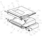
次に、カートリッジBに搭載する記憶媒体101(基板の内部に記憶素子を備え、基板上に電気接点を備える)について、図1、図12、図14、図15、図21(a)を用いて説明する。図1はカートリッジBを挿入方向下流側から見た図、図12はカートリッジBの分解図、図14は記憶媒体101の組立の様子の説明図、図15(a)(b)は記憶媒体101取付前の駆動側現像サイド部材26の正面図と側面図である。また、図21(a)は記憶媒体の設置に関する概観図である。
(Structure of storage medium and mounting configuration of storage medium)
Next, with respect to the
図14において、F方向は上下方向、G方向は前後方向、H方向は左右方向(ドラム62の回転軸線方向)である。また、C方向はカートリッジBの装置本体への挿入方向(装着方向)であり、またトレイ18の移動方向である。
In FIG. 14, the F direction is the vertical direction, the G direction is the front-rear direction, and the H direction is the left-right direction (direction of the rotation axis of the drum 62). Further, the C direction is the insertion direction (mounting direction) of the cartridge B into the apparatus main body, and the moving direction of the
本実施形態におけるプロセスカートリッジとしてのカートリッジBは、ドラム62(像担持体)を支持する第1軸受部73a(第1の軸受部)を備えるクリーニングユニット60(第1のユニット、像担持体ユニット)を備える。また、カートリッジBは、現像ローラ32(現像剤担持体)を支持する第2軸受部27a(第2の軸受部)を備える現像ユニット20(第2のユニット、現像担持体ユニット)を備える。そして、記録媒体101は現像ユニット20(第2のユニット)に支持される。
The cartridge B as a process cartridge in the present embodiment is a cleaning unit 60 (first unit, image carrier unit) including a
ここで、図1、図10、図12に示すように、ドラム62の回転軸線方向において、ドラム62を支持するドラム軸受部材73の第1軸受部73aより、現像ローラ32を支持する軸受部材27の第2軸受部27aは内側にある。なお、第1軸受部73a、第2軸受部27aとは、それぞれドラム62、現像ローラ32を軸支する穴の表面部分である。
Here, as shown in FIGS. 1, 10, and 12, the bearing
そして、記憶媒体101は、現像ユニット20の駆動側現像サイド部材26に支持され、ドラム62の回転軸線方向において、第2軸受部27aより外側かつクリーニングユニット60の最外形60aより内側に配置されている。このときの回転軸線方向における記憶媒体の設置範囲として、概念図を図21(b)に示している。
The
本実施形態においては、記憶媒体は図21(b)の範囲Zの内部として支持される現像ユニットの回転軸線方向の端部位置に配置される。なお、記憶媒体は、その少なくとも一部が、回転軸線方向において、一方のユニットにおける軸受部(第1の軸受部73a)と他方のユニットにおける軸受部(第2の軸受部27a)との間に設けられても良い。
In the present embodiment, the storage medium is arranged at the end position in the rotation axis direction of the developing unit supported as the inside of the range Z in FIG. 21 (b). At least a part of the storage medium is between the bearing portion (first bearing
そして、記憶媒体101は、カートリッジBの装置本体Aへの挿入方向において、ドラム62よりも上流側かつ下方に設けられ(図4)、ドラム62の回転軸線方向に挿入口を有する(図14)。
The
図14に示すように、RAMやROM等の記憶素子である記憶媒体101は、後述するように電気接点(接点部101a1、101a2として複数備える)を基板101b上で搬送方向(トレイの装置本体への装着方向)下流側に有している。そして、この記憶媒体101にカートリッジに関する情報Bを予め入力しておき、カートリッジBを画像形成装置Aに装着した時に、画像形成装置A側と情報をやり取りする。即ち、カートリッジBの使用状況等の状態を画像形成装置Aの制御基板(不図示)に報知し、画像形成動作に役立てたり、操作者にカートリッジBの状態を表示する等の目的のために使用される。
As shown in FIG. 14, the
また、記憶媒体101には使用中でも書き込みができるので、必要に応じて随時書込みが行われる。接点部101a1、101a2は、記憶媒体101に情報の読み書きをするために画像形成装置A装置の後述する本体接点102と接続するためのものである。
Further, since the
図14および図15(b)に示すように、駆動側現像サイド部材26には、記憶媒体第1規制面26b1、26b2、記憶媒体第2規制面26c1、26c2、26c3、26c4、で形成される挿入口としての挿入溝26fが設けられている。ここで、記憶媒体の装着時に挿入するとき、挿入口としての挿入溝26fが重力方向の下方にないため、記憶媒体が落ちにくいという利点がある。また、挿入溝26fの奥には記憶媒体第三規制面26d、入口にはスナップフィット26eが設けられている。
As shown in FIGS. 14 and 15B, the drive-side developing
また、挿入溝26fの近傍には、画像形成装置A側の後述する第1ホルダ部材104の位置を規制するホルダ第1規制面26g1、26g2、ホルダ第2規制面26hで形成されるラフガイド溝26iが設けられている。更に、挿入溝26fの近傍には、画像形成装置A側の後述する本体接点102の位置を規制する位置決めリブ26k1、26k2、位置決め面26m1、26m2、26m3,26m4、突き当て面26nが設けられている。
Further, in the vicinity of the insertion groove 26f, a rough guide groove formed by the holder first regulation surfaces 26g1 and 26g2 and the holder
次に図14、図15を用いて、記憶媒体101を駆動側現像サイド部材26に固定する方法について説明する。記憶媒体101をスナップフィット26eを弾性変形させながら、挿入溝26fに向かって矢印M方向(図14)に挿入すると、記憶媒体第1規制面26b1、26b2によって上下方向である矢印F方向(図15(b))の位置が規制される。
Next, a method of fixing the
また,記憶媒体第2規制面26c1、26c2、26c3、26c4によって、矢印G方向(図15(b))の位置が規制される。更に、記憶媒体第三規制面26dとスナップフィット26eによって矢印H方向(図15(a))の位置が規制される。このようにして、記憶媒体101は駆動側現像サイド部材26に固定される。
Further, the position in the arrow G direction (FIG. 15B) is regulated by the second regulation surface 26c1, 26c2, 26c3, 26c4 of the storage medium. Further, the position in the arrow H direction (FIG. 15A) is regulated by the storage medium third regulating
(本体接点の構成および本体接点の取付け構成)
次に、画像形成装置Aに設けられた本体接点102の構成および本体接点102の取付け構成について、図16、図17を用いて説明する。図16は本体接点102、ばね103、第1ホルダ部材104、ばね105、第2ホルダ部材106の分解斜視図、図17は本体接点102、第1ホルダ部材104、第2ホルダ部材106の組立状態の説明図で図17(a)が側面図、図17(b)が正面図である。
(Main body contact configuration and main body contact mounting configuration)
Next, the configuration of the
本体接点102には、記憶媒体101と電気的に接続されるばね材で構成された三角形状の接点部102a1、102a2が設けられている。このばね性の接点部102a1、102a2は、画像形成装置A側の制御基板に束線を介して電気的に接続されている(不図示)。
The
また、本体接点102には、駆動側現像サイド部材26との位置決めのため、被位置決め凸部102b1、102b2、102b3、102b4が接点部102a1、102a2の上下方向に設けられている。更に本体接点102には、駆動側現像サイド部材26の突き当て面26n(図14)が当接する被突き当て面102c1、102c2が、設けられている。
Further, the
そして、図16、図17(b)で、本体接点102には、上下方向に第1ホルダ部材104との位置決めのための第1規制部102d1、102d2と、脱落を規制するための脱落規制部102f1、102f2が設けられている。また、本体接点102には、左右方向(カートリッジ挿入方向に直交する方向)に第1ホルダ部材104との位置決めのための第2規制部102e1、102e2が設けられている。
Then, in FIGS. 16 and 17B, the
一方、第1ホルダ部材104には、本体接点102との上下方向の位置決めのための第1規制部104a1、104a2と、脱落を規制するための脱落規制部104c1、104c2が設けられている。また、第1ホルダ部材104には、本体接点102との左右方向の位置決めのための第2規制部104b1、104b2が設けられている。
On the other hand, the
また、図16、図17(b)で、第1ホルダ部材104には、第2ホルダ部材106との位置決めのため、規制ボス104d1、104d2、104d3、104d4が設けられている。更に、第1ホルダ部材104には、駆動側サイド部材26のラフガイド溝26i(図15(a))と係合する凸部104e(図14、図16)が設けられている。一方、第2ホルダ部材106には、第1ホルダ部材104との位置決めのため、規制ボス104d1、104d2、104d3、104d4が挿入される長穴106a1、106a2が設けられている。
Further, in FIGS. 16 and 17 (b), the
(本体接点、第1ホルダ部材、第2ホルダ部材の組立構成)
次に、本体接点102、第1ホルダ部材104、第2ホルダ部材106の組立構成について、図16、図17を用いて説明する。
(Assembly configuration of main body contact, first holder member, second holder member)
Next, the assembly configuration of the
先ず、図16で、本体接点102は、第1ホルダ部材104に対して、互いの間にカートリッジ挿入方向(図17のI方向およびJ方向に直交する方向)に付勢されるばね103を挟んだ状態で組付けられる。このとき、上下方向の第1規制部102d1、102d2と、上下方向の第1規制部104a1、104a2の係合によって、上下方向(図17の矢印J方向)にガタを有した状態で位置規制される。
First, in FIG. 16, the
また、本体接点102の左右方向の第2規制部102e1、102e2と、第1ホルダ部材104の左右方向の第2規制部104b1、104b2の係合によって左右方向(図17の矢印I方向)にガタを有した状態で位置規制される。
Further, due to the engagement between the second regulation portions 102e1 and 102e2 in the left-right direction of the
そして、本体接点102の脱落規制部102f1、102f2と、第1ホルダ部材104の脱落規制部104c1、104c2が当接することにより、カートリッジ挿入方向に付勢されるばね103の付勢力を受ける。
Then, the dropout restricting portions 102f1 and 102f2 of the
また、第1ホルダ部材104は、第2ホルダ部材106に対して、互いの間に上下方向(図17のJ方向)に付勢されるバネ105を挟んだ状態で組付けられる。このとき、第1ホルダ部材104の規制ボス104d1、104d2、104d3、104d4と、第2ホルダ部材106の長穴106a1、106a2の係合によって、第1ホルダ部材104は上下方向(図17のJ方向)に移動可能となっている。
Further, the
(記憶媒体と本体接点の接続動作)
図14、図16、図18、図19、図20を用いて、記憶媒体101と本体接点102の接続動作について説明する。図18、図19、図20は本体接点102と記憶媒体101が接続する様子の説明図であり、図18(a)、図19(a)、図20(a)は側面図、図18(b)、図19(b)、図20(b)は下面図である
先ず、図18(a)(b)で、矢印K方向(カートリッジBの挿入方向)にカートリッジBを挿入すると、駆動側現像サイド部材26のラフガイド溝26i(図15(a))に第1ホルダ部材104の凸部104e(図14、図16、図18(b))が入り込む。そして、駆動側現像サイド部材26の第1規制面26g1、26g2(下面図である図18(b))が凸部104eを挟むことで、駆動側現像サイド部材26に対して第1ホルダ部材104の長手方向の位置が規制される。
(Connection operation between storage medium and main unit contact)
The connection operation between the
また、駆動側現像サイド部材26の第2規制面26h(図15(a)、図18(b))が凸部104eを押し下げることで、ばね105(図16)を圧縮しながら、第1ホルダ部材104は駆動側現像サイド部材26に追従して下に移動する。
Further, the
更に矢印K方向に挿入すると、図14に示す駆動側現像サイド部材26の位置決めリブ26k1、26k2、位置決め面26m1、26m2、26m3、26m4が、本体接点102の被位置決め凸部102b1、102b2、102b3、102b4に入り込む。これにより、駆動側現像サイド部材26と本体接点102が精度良く位置決めされる。
When further inserted in the direction of arrow K, the positioning ribs 26k1, 26k2 and the positioning surfaces 26m1, 26m2, 26m3, 26m4 of the drive-side developing
そして、カートリッジBの装置本体Aへの装着が完了すると、駆動側現像サイド部材26の突き当て面26n(図14、図20)が、本体接点102の被突き当て面102c1、102c2(図16)に当接し、ばね103(図16)が圧縮される。また、記憶媒体101の接点部101a1、101a2の当接によって、本体接点102のばね材で構成された三角形状の接点部102a1、102a2が圧縮される。
Then, when the mounting of the cartridge B on the device main body A is completed, the abutting
ここで,ばね103(図16)の付勢力は、本体接点102の接点部102a1、102a2の付勢力の合計値よりも大きく設定してあるため、記憶媒体101と本体接点102に所望の接点圧を確保することができる。
Here, since the urging force of the spring 103 (FIG. 16) is set to be larger than the total value of the urging forces of the contact portions 102a1 and 102a2 of the
以上説明したように、本実施形態では、クリーニングユニット60と現像ユニット20の長手方向の長さの差によって生じた範囲に記憶媒体101と位置決め構成を設けた。これにより、装置本体Aの本体接点102と記憶媒体101の位置決めのために、新たにスペースを設ける必要がない。よって、安定した電気接続を実現できると共に、装置本体AおよびカートリッジBの小型化や低コスト化も実現できる。
As described above, in the present embodiment, the
(記録媒体の電気接点の配置方向)
更に、本実施形態では、図18、図19、図20に示すように、記憶媒体101の電気接点である接点部101a1、101a2の少なくとも一部は、カートリッジBの挿入方向(装着方向)下流側を向いて配置される。そのため、本実施形態では、簡単な構成で記憶媒体101と本体接点102を接続することができる。
(Arrangement direction of electrical contacts of recording medium)
Further, in the present embodiment, as shown in FIGS. 18, 19, and 20, at least a part of the contact portions 101a1 and 101a2, which are the electrical contacts of the
つまり、挿入方向の下流側からカートリッジを見た場合に、記憶媒体の電気接点の面が見える状態である。電気接点も複数の面を有する場合があり、本実施形態では一番広い面が見える状態になっている。広い面は挿入方向に対して直交するような位置に面が配置されることに限られず、挿入方向に対して傾斜するように電気接点の面を配置しても良い。 That is, when the cartridge is viewed from the downstream side in the insertion direction, the surface of the electrical contact of the storage medium can be seen. The electrical contact may also have a plurality of surfaces, and in the present embodiment, the widest surface can be seen. The wide surface is not limited to the surface arranged at a position orthogonal to the insertion direction, and the surface of the electric contact may be arranged so as to be inclined with respect to the insertion direction.
仮に接点部101a1、101a2が挿入方向下流側を向いていないと、カートリッジBの挿入方向にも本体接点102を追従させる機構が必要になる可能性がある。もしくは、カートリッジBの装着完了後、開閉扉13を閉じる動作に連動して、本体接点102を記憶媒体101に係合させる機構が必要になる可能性がある。
If the contact portions 101a1 and 101a2 do not face the downstream side in the insertion direction, a mechanism for following the
本実施形態では、カートリッジBの挿入方向、記憶媒体101と本体接点102の位置決め方向、本体接点102の接点部102a1、102a2の圧縮方向、が一致しており、上記の追従させる機構とか係合させる機構を必要としない。ここで、下流側を向いているとは、画像形成装置の装置本体における電気接点と正対する場合の他、傾いて対向するものであっても良い。
In the present embodiment, the insertion direction of the cartridge B, the positioning direction of the
(変形例)
以上、本発明の好ましい実施形態について説明したが、本発明はこれらの実施形態に限定されず、その要旨の範囲内で種々の変形及び変更が可能である。因みに、本実施形態に記載されている構成部品の機能、材質、形状その相対配置などは、特に特定的な記載がない限りは、この発明の範囲をそれらのみに限定する趣旨のものではない。
(Modification example)
Although the preferred embodiments of the present invention have been described above, the present invention is not limited to these embodiments, and various modifications and modifications can be made within the scope of the gist thereof. Incidentally, the functions, materials, shapes, and relative arrangements of the components described in the present embodiment are not intended to limit the scope of the present invention to those, unless otherwise specified.
(変形例1)
上述した実施形態では、現像ローラ32を支持する第2軸受部である軸受部材27が、ドラム62を支持するドラム軸受部材73の第1軸受部73aより内側にある構成について説明した。しかし、長手方向の位置関係が逆である構成、つまりドラム62を支持するドラム軸受部材73の第1軸受部73aが、現像ローラ32を支持する軸受部材27の第2軸受部27aより内側にある構成に適用しても良い。
(Modification example 1)
In the above-described embodiment, the configuration in which the bearing
この場合、記憶媒体101は、第1のユニットであるクリーニングユニット60で支持し、第1軸受部73aより外側かつ現像ユニット20の最外形より内側に配置すれば良い。そうすれば、クリーニングユニット60と現像ユニット20の長手方向の長さの差によって生じた範囲に記憶媒体101を設けることになり、同様の効果を得ることができる。
In this case, the
(変形例2)
上述した実施形態では、プロセスカートリッジとしてのカートリッジBについて説明した。即ち、像担持体を支持する第1の軸受部を備える第1のユニットと、現像剤担持体を支持する第2の軸受部を備える第2のユニットと、電気接点を備える記憶媒体と、を備え、装置本体に対し挿入可能なカートリッジについて述べた。
(Modification 2)
In the above-described embodiment, the cartridge B as a process cartridge has been described. That is, a first unit having a first bearing portion that supports the image carrier, a second unit having a second bearing portion that supports the developer carrier, and a storage medium having electrical contacts. The cartridge that can be inserted into the main body of the device is described.
しかし、本発明はこれに限定されず、プロセスカートリッジとしての現像カートリッジや像担持体カートリッジ(感光体カートリッジ)にも適用できるものである。即ち、現像カートリッジとして、現像剤担持体を支持する現像軸受部を備える現像ユニットと、電気接点を備える記憶媒体と、を有し、画像形成装置の装置本体に対し挿入可能なカートリッジであっても良い。 However, the present invention is not limited to this, and can be applied to a developing cartridge as a process cartridge and an image carrier cartridge (photoreceptor cartridge). That is, even if the developing cartridge has a developing unit having a developing bearing portion that supports the developing agent carrier and a storage medium having electrical contacts, and can be inserted into the main body of the image forming apparatus. good.
この場合、現像剤担持体の回転軸線方向において、現像軸受部は像担持体軸受部の内側に設けられる。そして、記憶媒体の少なくとも一部は、現像ユニットに支持され、回転軸線方向において、現像軸受部より外側で、かつ像担持体軸受部を有する像担持体ユニットの最外形より内側となる位置に設けられる。ここで、電気接点は、装置本体への挿入方向で下流側に向いている。 In this case, the developing bearing portion is provided inside the image bearing portion in the direction of the rotation axis of the developing agent carrier. Then, at least a part of the storage medium is supported by the developing unit, and is provided at a position outside the developing bearing portion and inside the outermost shape of the image bearing unit having the image bearing bearing portion in the direction of the rotation axis. Be done. Here, the electrical contacts face downstream in the direction of insertion into the device body.
また、像担持体カートリッジ(感光体カートリッジ)として、像担持体を支持する像担持体軸受部を備える像担持体ユニットと、電気接点を備える記憶媒体と、を有し、画像形成装置の装置本体に対し挿入可能なカートリッジであっても良い。 Further, as the image carrier cartridge (photoreceptor cartridge), the apparatus main body of the image forming apparatus includes an image carrier unit including an image carrier bearing portion that supports the image carrier, and a storage medium provided with electrical contacts. It may be a cartridge that can be inserted into the cartridge.
この場合、像担持体の回転軸線方向において、像担持体軸受部は現像軸受部の内側に設けられる。そして、記憶媒体の少なくとも一部は、像担持体ユニットに支持され、回転軸線方向において、像担持体軸受部より外側で、かつ現像軸受部を有する現像担持体ユニットの最外形より内側となる位置に設けられる。ここで、電気接点は、前記装置本体への挿入方向で下流側に向いている。 In this case, the image carrier bearing portion is provided inside the developed bearing portion in the direction of the rotation axis of the image carrier. Then, at least a part of the storage medium is supported by the image carrier unit, and is located outside the image carrier bearing portion and inside the outermost shape of the developing carrier unit having the developing bearing portion in the direction of the rotation axis. It is provided in. Here, the electrical contacts face downstream in the direction of insertion into the device body.
15b・・支持部、26n・・突き当て面、27a・・第2軸受部、32・・現像ローラ、62・・ドラム、73a・・第1軸受部、73d・・被支持部、101・・記憶媒体、102a1,102a2・・接点部、102c1,102c2・・被突き当て面、A・・画像形成装置の装置本体、B・・カートリッジ 15b ... Support part, 26n ... Butt surface, 27a ... Second bearing part, 32 ... Development roller, 62 ... Drum, 73a ... First bearing part, 73d ... Supported part, 101 ... Storage medium, 102a1, 102a2 ... contact part, 102c1, 102c2 ... abutment surface, A ... device body of image forming apparatus, B ... cartridge
Claims (15)
前記像担持体に形成された静電潜像を現像剤で現像する現像剤担持体を支持する第2の軸受部を備える第2のユニットと、
前記第2のユニットに支持され、電気接点面を備える記憶媒体と、を有し、
画像形成装置の装置本体に対し挿入可能なカートリッジであって、
前記像担持体の回転軸線方向において、前記第2の軸受部は前記第1の軸受部の内側に設けられ、
前記記憶媒体の少なくとも一部は、前記回転軸線方向において、前記第2の軸受部より外側で、かつ前記第1のユニットの最外形より内側となる位置に設けられ、
前記電気接点面は、前記カートリッジの下部に配置され、更に、前記回転軸線方向に交差する方向を向き、前記カートリッジの前記装置本体への挿入方向に対して傾斜しており、前記装置本体の本体接点に接続される際に前記装置本体の本体接点に対向するように配置されていることを特徴とするカートリッジ。 A first unit having a first bearing portion that supports the image carrier, and
A second unit including a second bearing portion that supports the developer carrier for developing the electrostatic latent image formed on the image carrier with a developer, and a second unit.
A storage medium supported by the second unit and provided with an electrical contact surface.
A cartridge that can be inserted into the main body of an image forming device.
The second bearing portion is provided inside the first bearing portion in the direction of the rotation axis of the image carrier.
At least a portion of the storage medium, before Symbol rotational axis direction, at the outer side of the second bearing portion, and provided at positions which are inside the outermost of said first unit,
The electrical contact surface is arranged at the lower part of the cartridge, is oriented in a direction intersecting the rotation axis direction, and is inclined with respect to the insertion direction of the cartridge into the apparatus main body, and is inclined with respect to the insertion direction of the apparatus main body. A cartridge characterized in that it is arranged so as to face the main body contact of the device main body when connected to the contact.
前記回転軸線方向において、前記記憶媒体は、前記回転軸線方向における前記被支持部の外側の端部位置よりも内側に位置することを特徴とする請求項1乃至4のいずれか1項に記載のカートリッジ。 The first unit is a supported portion that projects outward from the first bearing portion in the direction of the rotation axis, and is provided on the device main body when the cartridge is inserted into the device main body. It has a supported part that comes into contact with the bearing part and is supported.
The method according to any one of claims 1 to 4, wherein the storage medium is located inside the position of the outer end of the supported portion in the direction of the rotation axis. cartridge.
前記第2のユニットは、前記被突き当て面に突き当たる突き当て面であって、前記回転軸線方向において前記第1のユニットの最外形より内側となる位置に設けられた突き当て面を有し、
前記カートリッジが前記装置本体に挿入される場合に、前記突き当て面と前記被突き当て面とが突き当たる前及び突き当たった状態で、前記カートリッジの前記電気接点面により前記接点部が前記挿入方向の下流側に押圧されていることを特徴とする請求項1乃至5のいずれか1項に記載のカートリッジ。 The main body contacts of the apparatus main body are contact portions connected to the abutting surface and the electrical contact surface of the storage medium, and have a spring property that can move relative to the abutting surface. And, equipped with
The second unit has an abutting surface that abuts against the abutted surface, and has an abutting surface provided at a position inside the outermost shape of the first unit in the direction of the rotation axis.
When the cartridge is inserted into the main body of the apparatus, the contact portion is downstream of the insertion direction by the electrical contact surface of the cartridge before and in the state where the abutting surface and the abutted surface abut each other. The cartridge according to any one of claims 1 to 5, wherein the cartridge is pressed to the side.
前記装置本体に対して着脱可能に装着される請求項1乃至14の何れか1項に記載のカートリッジと、
を有し、前記カートリッジを用いて記録材に画像を形成することを特徴とする画像形成装置。 With the device body
The cartridge according to any one of claims 1 to 14 , which is detachably attached to the apparatus main body.
An image forming apparatus comprising the above and forming an image on a recording material using the cartridge.
Priority Applications (1)
| Application Number | Priority Date | Filing Date | Title |
|---|---|---|---|
| JP2019140309A JP6849753B2 (en) | 2019-07-30 | 2019-07-30 | Cartridge and image forming device using it |
Applications Claiming Priority (1)
| Application Number | Priority Date | Filing Date | Title |
|---|---|---|---|
| JP2019140309A JP6849753B2 (en) | 2019-07-30 | 2019-07-30 | Cartridge and image forming device using it |
Related Parent Applications (1)
| Application Number | Title | Priority Date | Filing Date |
|---|---|---|---|
| JP2014234154A Division JP6566627B2 (en) | 2014-11-19 | 2014-11-19 | Cartridge and image forming apparatus using the same |
Publications (2)
| Publication Number | Publication Date |
|---|---|
| JP2019204116A JP2019204116A (en) | 2019-11-28 |
| JP6849753B2 true JP6849753B2 (en) | 2021-03-31 |
Family
ID=68726877
Family Applications (1)
| Application Number | Title | Priority Date | Filing Date |
|---|---|---|---|
| JP2019140309A Active JP6849753B2 (en) | 2019-07-30 | 2019-07-30 | Cartridge and image forming device using it |
Country Status (1)
| Country | Link |
|---|---|
| JP (1) | JP6849753B2 (en) |
Family Cites Families (10)
| Publication number | Priority date | Publication date | Assignee | Title |
|---|---|---|---|---|
| JPH10228223A (en) * | 1997-02-14 | 1998-08-25 | Canon Inc | Process cartridge and electrophotographic image forming device |
| JP3981518B2 (en) * | 2000-08-25 | 2007-09-26 | 株式会社リコー | Image forming apparatus |
| JP3796442B2 (en) * | 2001-12-28 | 2006-07-12 | キヤノン株式会社 | Image forming apparatus unit, process cartridge, and image forming apparatus |
| JP4386616B2 (en) * | 2002-03-04 | 2009-12-16 | セイコーエプソン株式会社 | Connector, developing cartridge, and image forming apparatus |
| JP4455124B2 (en) * | 2004-03-31 | 2010-04-21 | キヤノン株式会社 | Electrophotographic image forming apparatus |
| JP2007047399A (en) * | 2005-08-09 | 2007-02-22 | Canon Inc | Process cartridge, developing device and electrophotographic image forming apparatus |
| JP2009003174A (en) * | 2007-06-21 | 2009-01-08 | Brother Ind Ltd | Image forming apparatus, developing cartridge, and photoreceptor unit |
| JP2009031376A (en) * | 2007-07-25 | 2009-02-12 | Canon Inc | Electrophotographic image forming apparatus |
| JP2013174653A (en) * | 2012-02-23 | 2013-09-05 | Canon Inc | Cartridge and image forming apparatus |
| JP5250139B2 (en) * | 2012-07-06 | 2013-07-31 | 株式会社沖データ | Image forming apparatus |
-
2019
- 2019-07-30 JP JP2019140309A patent/JP6849753B2/en active Active
Also Published As
| Publication number | Publication date |
|---|---|
| JP2019204116A (en) | 2019-11-28 |
Similar Documents
| Publication | Publication Date | Title |
|---|---|---|
| JP6566627B2 (en) | Cartridge and image forming apparatus using the same | |
| US8213828B2 (en) | Electrophotographic image forming apparatus and process cartridge mounted thereto having contacts electrically connecting with an electrical contact | |
| US7894733B2 (en) | Process cartridge and image forming apparatus | |
| US12228877B2 (en) | Process cartridge and image forming apparatus | |
| US10962927B2 (en) | Cartridge and imaging forming apparatus | |
| JP6849753B2 (en) | Cartridge and image forming device using it | |
| JP6957199B2 (en) | Photoreceptor unit | |
| JP6639183B2 (en) | Process cartridge and image forming apparatus | |
| JP6833402B2 (en) | Cartridge and image forming device | |
| KR20190089783A (en) | Cartridge and image forming apparatus | |
| JP6789683B2 (en) | Image forming device | |
| JP6808311B2 (en) | Electrophotographic photosensitive drum unit, cartridge, and flange member | |
| JP2007057964A (en) | Developing cartridge and process unit | |
| JP7500266B2 (en) | Cartridge and image forming apparatus | |
| US9513578B2 (en) | Developing device, process cartridge and image forming apparatus | |
| JP6896376B2 (en) | Cartridge and image forming device | |
| JP2023026759A (en) | Cartridge reproduction method, cartridge reproduction system, and cartridge |
Legal Events
| Date | Code | Title | Description |
|---|---|---|---|
| A521 | Written amendment |
Free format text: JAPANESE INTERMEDIATE CODE: A523 Effective date: 20190806 |
|
| A621 | Written request for application examination |
Free format text: JAPANESE INTERMEDIATE CODE: A621 Effective date: 20190809 |
|
| RD02 | Notification of acceptance of power of attorney |
Free format text: JAPANESE INTERMEDIATE CODE: A7422 Effective date: 20200206 |
|
| RD04 | Notification of resignation of power of attorney |
Free format text: JAPANESE INTERMEDIATE CODE: A7424 Effective date: 20200207 |
|
| A977 | Report on retrieval |
Free format text: JAPANESE INTERMEDIATE CODE: A971007 Effective date: 20200715 |
|
| A131 | Notification of reasons for refusal |
Free format text: JAPANESE INTERMEDIATE CODE: A131 Effective date: 20200804 |
|
| A521 | Written amendment |
Free format text: JAPANESE INTERMEDIATE CODE: A523 Effective date: 20201005 |
|
| TRDD | Decision of grant or rejection written | ||
| A01 | Written decision to grant a patent or to grant a registration (utility model) |
Free format text: JAPANESE INTERMEDIATE CODE: A01 Effective date: 20210202 |
|
| A61 | First payment of annual fees (during grant procedure) |
Free format text: JAPANESE INTERMEDIATE CODE: A61 Effective date: 20210304 |
|
| R151 | Written notification of patent or utility model registration |
Ref document number: 6849753 Country of ref document: JP Free format text: JAPANESE INTERMEDIATE CODE: R151 |