JP6837127B2 - Surgical ligature clip - Google Patents
Surgical ligature clip Download PDFInfo
- Publication number
- JP6837127B2 JP6837127B2 JP2019506083A JP2019506083A JP6837127B2 JP 6837127 B2 JP6837127 B2 JP 6837127B2 JP 2019506083 A JP2019506083 A JP 2019506083A JP 2019506083 A JP2019506083 A JP 2019506083A JP 6837127 B2 JP6837127 B2 JP 6837127B2
- Authority
- JP
- Japan
- Prior art keywords
- leg member
- tissue
- surgical clip
- clip
- convex
- Prior art date
- Legal status (The legal status is an assumption and is not a legal conclusion. Google has not performed a legal analysis and makes no representation as to the accuracy of the status listed.)
- Active
Links
Images


Classifications
-
- A—HUMAN NECESSITIES
- A61—MEDICAL OR VETERINARY SCIENCE; HYGIENE
- A61B—DIAGNOSIS; SURGERY; IDENTIFICATION
- A61B17/00—Surgical instruments, devices or methods
- A61B17/12—Surgical instruments, devices or methods for ligaturing or otherwise compressing tubular parts of the body, e.g. blood vessels or umbilical cord
- A61B17/122—Clamps or clips, e.g. for the umbilical cord
-
- A—HUMAN NECESSITIES
- A61—MEDICAL OR VETERINARY SCIENCE; HYGIENE
- A61B—DIAGNOSIS; SURGERY; IDENTIFICATION
- A61B17/00—Surgical instruments, devices or methods
- A61B17/08—Wound clamps or clips, i.e. not or only partly penetrating the tissue ; Devices for bringing together the edges of a wound
- A61B17/083—Clips, e.g. resilient
-
- A—HUMAN NECESSITIES
- A61—MEDICAL OR VETERINARY SCIENCE; HYGIENE
- A61B—DIAGNOSIS; SURGERY; IDENTIFICATION
- A61B17/00—Surgical instruments, devices or methods
- A61B17/0057—Implements for plugging an opening in the wall of a hollow or tubular organ, e.g. for sealing a vessel puncture or closing a cardiac septal defect
- A61B2017/00575—Implements for plugging an opening in the wall of a hollow or tubular organ, e.g. for sealing a vessel puncture or closing a cardiac septal defect for closure at remote site, e.g. closing atrial septum defects
- A61B2017/00588—Rigid or stiff implements, e.g. made of several rigid parts linked by hinges
-
- A—HUMAN NECESSITIES
- A61—MEDICAL OR VETERINARY SCIENCE; HYGIENE
- A61B—DIAGNOSIS; SURGERY; IDENTIFICATION
- A61B17/00—Surgical instruments, devices or methods
- A61B2017/00831—Material properties
- A61B2017/00858—Material properties high friction or non-slip
-
- A—HUMAN NECESSITIES
- A61—MEDICAL OR VETERINARY SCIENCE; HYGIENE
- A61B—DIAGNOSIS; SURGERY; IDENTIFICATION
- A61B17/00—Surgical instruments, devices or methods
- A61B2017/00831—Material properties
- A61B2017/00862—Material properties elastic or resilient
-
- A—HUMAN NECESSITIES
- A61—MEDICAL OR VETERINARY SCIENCE; HYGIENE
- A61B—DIAGNOSIS; SURGERY; IDENTIFICATION
- A61B17/00—Surgical instruments, devices or methods
- A61B17/08—Wound clamps or clips, i.e. not or only partly penetrating the tissue ; Devices for bringing together the edges of a wound
- A61B17/085—Wound clamps or clips, i.e. not or only partly penetrating the tissue ; Devices for bringing together the edges of a wound with adhesive layer
- A61B2017/086—Wound clamps or clips, i.e. not or only partly penetrating the tissue ; Devices for bringing together the edges of a wound with adhesive layer having flexible threads, filaments, laces or wires, e.g. parallel threads, extending laterally from a strip, e.g. for tying to opposing threads extending from a similar strip
Landscapes
- Health & Medical Sciences (AREA)
- Surgery (AREA)
- Life Sciences & Earth Sciences (AREA)
- Heart & Thoracic Surgery (AREA)
- Nuclear Medicine, Radiotherapy & Molecular Imaging (AREA)
- Engineering & Computer Science (AREA)
- Biomedical Technology (AREA)
- Medical Informatics (AREA)
- Molecular Biology (AREA)
- Animal Behavior & Ethology (AREA)
- General Health & Medical Sciences (AREA)
- Public Health (AREA)
- Veterinary Medicine (AREA)
- Vascular Medicine (AREA)
- Reproductive Health (AREA)
- Surgical Instruments (AREA)
Description
本開示内容は、一般に、医療器具、特に組織の結紮のための外科用クリップに関する。 The present disclosure generally relates to medical devices, especially surgical clips for ligating tissue.
〔関連出願の引照〕
本開示内容は、2016年8月3日に出願された米国特許仮出願第62/370,502号の優先権主張出願であり、この米国特許仮出願を参照により引用し、その開示内容全体を本明細書の一部とする。
[Reference of related applications]
This disclosure is a priority claim application of U.S. Patent Provisional Application No. 62 / 370,502 filed on August 3, 2016. It is a part of this specification.
組織(例えば、血管、リンパ節、神経、ファロピウス管、又は心組織)の結紮は、多くの外科的処置のありふれた手技である。例えば、血管(例えば、静脈又は動脈)を結紮することは、例えば動脈瘤を除去するために血管の切除中に必要とされる場合が多い。組織の結紮は、血管を結紮クリップで閉じることにより又は血管を外科用糸で縫合することによって実施される場合がある。結紮のために縫合糸を用いることにより、血管を固定するのに必要な結び目を作るために針及び縫合材料の複雑な操作が必要である。かかる複雑な操作は、特にスペース及び視認性が制限されることを特徴とする内視鏡外科的処置の際、時間がかかりかつ実施するのが困難である。これとは対照的に、結紮クリップは、止めるのが比較的容易でありかつ迅速である。したがって、内視鏡ならびに開放外科的処置の際に結紮クリップを用いることが飛躍的に増大している。 Ligation of tissue (eg, blood vessels, lymph nodes, nerves, Faropius ducts, or heart tissue) is a common procedure in many surgical procedures. For example, ligation of a blood vessel (eg, a vein or artery) is often required during excision of the blood vessel, eg, to remove an aneurysm. Tissue ligation may be performed by closing the blood vessel with a ligation clip or by suturing the blood vessel with a surgical thread. By using sutures for ligation, complex manipulation of needles and suture materials is required to tie the knots needed to secure the blood vessels. Such complex operations are time consuming and difficult to perform, especially during endoscopic surgical procedures characterized by limited space and visibility. In contrast, ligation clips are relatively easy and quick to stop. Therefore, the use of ligature clips during endoscopic and open surgical procedures has increased dramatically.
本発明者は、結紮クリップの1つ又は2つ以上の特徴、例えば組織の初期の保持及び圧力分布を向上させる必要があるということを認識している。例えば、現行の結紮クリップは、結紮クリップが閉じている状態で組織が結紮クリップから滑り抜けるときに望ましくない「ウォーターメロン・シーディング(watermelon-seeding):WMS」作用効果を生じる場合が多い。この作用効果の結果、望ましくないこととして、組織の損傷、長時間にわたる外科的処置、及び外科医が保持を行うために過度の力を組織に加える事態が生じる場合がある。さらに、現行の結紮クリップは、組織上で閉じられた後、非一様な圧力分布をもたらす場合が多い。例えば、現行の結紮クリップのレッグ部材は、典型的には、剛性であり、互いに異なるサイズの組織に適合せず、それにより応力集中が生じる。非一様な圧力分布は、組織がクリップ内に適正に位置決めされていない場合に特に問題となる場合があり、例えば、組織がヒンジ部分かラッチ止め機構体かのいずれかに隣接して位置決めされたときに過剰の圧迫又は圧排が生じる場合がある。この非一様な圧力分布の結果として、特に過剰に応力が加えられ、線維化したかつ/あるいは壊死した組織に加えられたときに組織の損傷及び/又は破断が起こる場合がある。さらに、現行の結紮クリップは、例えば束に含まれている組織の様々なサイズに起因して、組織の束を十分に結紮することはない。開示する方法及びシステムは、上述の問題及び/又は先行技術における他の問題のうちの1つ又は2つ以上を軽減し又は解決することを目的としている。 The inventor recognizes the need to improve one or more features of the ligation clip, such as initial retention of tissue and pressure distribution. For example, current ligature clips often produce unwanted "watermelon-seeding: WMS" effects when tissue slides out of the ligature clip while the ligature clip is closed. As a result of this effect, undesirably, tissue damage, lengthy surgical procedures, and excessive force exerted by the surgeon to hold the tissue may occur. In addition, current ligation clips often result in a non-uniform pressure distribution after being closed on the tissue. For example, the leg members of current ligature clips are typically rigid and do not fit into tissues of different sizes, resulting in stress concentration. Non-uniform pressure distribution can be particularly problematic if the tissue is not properly positioned within the clip, for example, the tissue is positioned adjacent to either the hinge portion or the latching mechanism. Excessive compression or exclusion may occur at the time. As a result of this non-uniform pressure distribution, tissue damage and / or fracture may occur, especially when overstressed and applied to fibrotic and / or necrotic tissue. Moreover, current ligation clips do not adequately ligate bundles of tissue, for example due to the various sizes of tissue contained in the bundle. The disclosed methods and systems are intended to mitigate or solve one or more of the above problems and / or other problems in the prior art.
1つ又は2つ以上の観点では、組織を結紮するよう構成された外科用クリップが第1のレッグ部材及び第2のレッグ部材を有するのが良い。第1のレッグ部材は、近位端部分、遠位端部分、凸状の第1の内面、及び凸状の第1の外面を備えた第1のレッグ部材を有するのが良い。第1のレッグ部材は、第1の内面を少なくとも部分的に構成する第1の内側部分及び第1の外面を少なくとも部分的に構成する第1の外側部分を更に有するのが良い。内側部分と外側部分は、第1のチャネルによって互いに隔てられた状態で第1のレッグ部材の第1及び第2の部分のところで互いに接合されるのが良い。第2のレッ部材は、近位端部分、遠位端部分、第2の内面、及び第2の外面を備えた第2のレッグ部材を有しするのが良い。第1のレッグ部材と第2のレッグ部材は、開き位置と閉じ位置との間で互いに対して動くことができ、第1の内面及び第2の内面は、閉じ位置にあるときに組織を結紮するよう構成されるのが良い。 From one or more perspectives, it is preferred that the surgical clip configured to ligate the tissue has a first leg member and a second leg member. The first leg member preferably has a first leg member having a proximal end portion, a distal end portion, a convex first inner surface, and a convex first outer surface. The first leg member may further include a first inner portion that at least partially constitutes the first inner surface and a first outer portion that at least partially constitutes the first outer surface. The inner and outer portions are preferably joined to each other at the first and second portions of the first leg member, separated from each other by the first channel. The second leg member preferably has a second leg member with a proximal end portion, a distal end portion, a second inner surface, and a second outer surface. The first leg member and the second leg member can move relative to each other between the open and closed positions, and the first and second inner surfaces ligate the tissue when in the closed position. It should be configured to do.
幾つかの観点では、第1の内側部分は、閉じ形態において弾性的に偏向されるよう構成されるのが良く、第1の内面は、凸状内面を含み、第1及び第2の内面は、外科用クリップが当初押し縮められたときに近位部分をはさむよう構成されるのが良く、第1の内側部分及び第2の外側部分は、第1のレッグ部材と一体であるのが良く、第1の内側部分は、第1の外側の部分の幅に実質的に等しい幅を有するのが良く、第1のチャネルは、第1のレッグ部材の長さの少なくとも半分にわたって長手方向に延びるのが良く、第1のチャネルは、第1のレッグ部材の長さの3/4を超える長さにわたって長手方向に延びるのが良く、ヒンジ部分が第1及び第2のレッグ部材の近位端部分を互いに接合するのが良く、ヒンジ部分は、第1及び第2のレッグ部材と一体であるのが良く、外科用クリップは、第1の内面に設けられた少なくとも1つの第1の歯と、第2の内面に設けられた少なくとも1つの第2の歯とを更に有するのが良く、第1及び第2のレッグ部材は、外科用クリップを閉じ形態で固定するよう構成されたラッチ止め要素を有するのが良く、第1及び第2のレッグ部材の各々は、少なくとも1つのボスを有するのが良く、第2のレッグ部材は、第2の内面を少なくとも部分的に構成する第2の内側部分及び第2の外面を少なくとも部分的に構成する第2の外側部分を含み第2の内側部分と第2の外側部分は、第2のチャネルによって互いに隔てられた状態で第2のレッグ部材の第1及び第2のところで互いに接合されるのが良く、第2の内側部分は、凸状の内面を有するのが良く、第2の外側部分は、凸状の外面を有するのが良く、第2の内側部分は、凹状の外面を有するのが良く、第2の外側部分は、凹状の内面を有するのが良い。 From some viewpoints, the first inner surface may be configured to be elastically deflected in a closed form, the first inner surface may include a convex inner surface, and the first and second inner surfaces may be. , The surgical clip should be configured to sandwich the proximal portion when initially compressed, and the first inner and second outer portions should be integrated with the first leg member. The first inner portion should have a width substantially equal to the width of the first outer portion, and the first channel extends longitudinally over at least half the length of the first leg member. The first channel should extend longitudinally over a length of more than 3/4 of the length of the first leg member, with the hinge portion at the proximal end of the first and second leg members. The portions should be joined together, the hinge portion should be integral with the first and second leg members, and the surgical clip should be with at least one first tooth provided on the first inner surface. , It may further have at least one second tooth provided on the second inner surface, the first and second leg members being a latching element configured to secure the surgical clip in a closed form. Each of the first and second leg members is preferably having at least one boss, the second leg member having a second inner surface that at least partially constitutes the second inner surface. The second inner portion and the second outer portion, including the second outer portion that at least partially constitutes the portion and the second outer surface, are of the second leg member in a state of being separated from each other by the second channel. It is good to be joined to each other at the first and second places, the second inner part is better to have a convex inner surface, and the second outer part is better to have a convex outer surface. The inner portion of 2 preferably has a concave outer surface, and the second outer portion preferably has a concave inner surface.
1つ又は2つ以上の観点では、第1のレッグ部材及び第2のレッグ部材を備えた外科用クリップにより組織を結紮するのが良い方法が提供される。第1のレッグ部材は、内側部分、外側部分、及び内側部分と外側部分との間に位置するチャネルを有するのが良い。本方法は、第1のレッグ部材を第2のレッグ部材に対して開き形態から閉じ形態に向かって動かすステップを含むのが良い。本方法は、組織を内側部分の凸状内面に係合させることによって組織の少なくとも一部分を第1のレッグ部材と第2のレッグ部材との間で圧迫するステップを更に含むのが良い。本方法は、組織が圧迫されているときに内側部分をチャネル中に弾性的に偏向させるステップを更に含むのが良い。 From one or more perspectives, a good method of ligating tissue with a surgical clip with a first leg member and a second leg member is provided. The first leg member preferably has an inner portion, an outer portion, and a channel located between the inner portion and the outer portion. The method may include moving the first leg member from the open form to the closed form with respect to the second leg member. The method may further include the step of compressing at least a portion of the tissue between the first leg member and the second leg member by engaging the tissue with the convex inner surface of the inner portion. The method may further include the step of elastically deflecting the medial portion into the channel when the tissue is compressed.
幾つかの観点では、内側部分を弾性的に偏向させるステップは、内側部分を第1のレッグ部材の外側部分の凹状内面に向かって弾性的に偏向させるステップを含むのが良く、本本発明は、組織の少なくとも一部分を圧迫後に組織を外科用クリップでレトラクトするステップと、組織を外科用クリップでレトラクトした後に外科用クリップを閉じ位置に動かすステップとを更に含むのが良く、本方法は、第1及び第2のレッグ部材に設けられたラッチ止め要素によって外科用クリップを閉じ位置に固定するステップを更に含むのが良い。 From some viewpoints, the step of elastically deflecting the inner portion may include the step of elastically deflecting the inner portion toward the concave inner surface of the outer portion of the first leg member. It is preferable to further include a step of retracting the tissue with a surgical clip after compressing at least a part of the tissue and a step of moving the surgical clip to the closed position after retracting the tissue with the surgical clip. And it may further include a step of fixing the surgical clip in the closed position by a latching element provided on the second leg member.
1つ又は2つ以上の観点では、組織を結紮するよう構成された外科用クリップが第1のレッグ部材及び第2のレッグ部材を有するのが良く、第1のレッグ部材は、凸状内面を備えた内側部分、外側部分、及び内側部分と外側部分の間に位置するチャネルを有するのが良い。第1のレッグ部材は、第2のレッグ部材に対して開き形態から閉じ形態に向かって動くよう構成されるのが良く、第1のレッグ部材及び第2のレッグ部材は、組織を凸状内面に係合させることによって組織の少なくとも一部分を圧迫するよう構成されるのが良く、内側部分は、組織が圧迫されているときにチャネル中に弾性的に偏向するよう構成されるのが良い。 From one or more perspectives, the surgical clip configured to ligate the tissue preferably has a first leg member and a second leg member, the first leg member having a convex inner surface. It is preferable to have an inner part, an outer part, and a channel located between the inner part and the outer part. The first leg member is preferably configured to move from an open form to a closed form with respect to the second leg member, and the first leg member and the second leg member have a convex inner surface of the structure. The inner portion may be configured to elastically deflect into the channel when the tissue is compressed, as it may be configured to compress at least a portion of the tissue by engaging with.
本開示内容を容易に理解できるようにするため、本開示内容の諸観点が添付の図面に例示として示されている。 In order to make the disclosure content easy to understand, various viewpoints of the disclosure content are illustrated in the accompanying drawings.
同一の参照符号が同一又は類似の部分を示すために図面及び以下の詳細な説明に用いられている。 The same reference numerals are used in the drawings and in the following detailed description to indicate the same or similar parts.
次に、図面を参照して本発明について説明するが、図中、同一の参照符号は、全体を通じて同一の部分を示している。本明細書で用いられる従来のやり方に従って、本明細書において別段の指定がなければ、「近位端部分」という用語は、器具が用いられるよう意図されたときに器具を取り扱い又は操作する医療関係者の全体的に近くに位置する器具又はそのコンポーネントの指定された端部分を意味し、「遠位端部分」という用語は、近位端部分と反対側に位置する器具又はそのコンポーネントの指定された端部分を意味している。 Next, the present invention will be described with reference to the drawings. In the drawings, the same reference numerals indicate the same parts throughout. In accordance with the conventional practice used herein, unless otherwise specified herein, the term "proximal end portion" is used in the medical context of handling or manipulating an instrument when it is intended to be used. The term "distal end" refers to a designated end of an instrument or component that is generally close to a person, and the term "distal end" is a designation of an instrument or component that is opposite the proximal end. It means the end part.
本発明は、一般に、組織(例えば、血管)を結紮するよう構成された外科用結紮クリップに関する。このクリップは、初期保持作用及び圧力分布具合を向上させるよう構成された第1及び第2のレッグ部材を有するのが良い。例えば、第1のレッグ部材は、クリップが当初押し縮められたときに組織の近位部分を第2のレッグ部材の凸状の表面に当ててはさむことができるようにする凸状部分を備えた内側部分(例えば、内側リブ)を有するのが良い。幾つかの実施形態では、組織をはさむことにより、組織を掴むことができ、それによりクリップが部分的に開いているときに組織の扱いが可能である。凸状面は、組織が更に圧迫されているときに組織を掴んでこれをクリップの近位端部分に向かって引く歯を更に有するのが良い。内側部分は、第1のレッグ部材の外側部分(例えば、外側リブ)の凹状内面に向かって弾性的に押し縮められるのが良くそれにより組織が結紮されているときに組織に対する望ましい圧力分布をもたらすことができる。内側部分の可撓性により、互いに異なる形状、寸法及び/又はスチフネスの組織に対して望ましい圧力分布をもたらすことができ、組織は、クリップの長さに沿って互いに異なる位置で圧迫される。これにより、例えば過剰に応力が加えられ、線維化したかつ/あるいは壊死した組織の結紮中における漏れ、組織損傷及び/又は破断を減少させることができる。さらに、内側部分の可撓性は、組織の束、例えば複数のリンパ節の結紮を促進することができる。内側部分の可撓性により、これが束の中の種々の組織の形状に一致することができ、他方、十分な圧力が束の中の組織の各々を結紮するよう加えられるようにする。 The present invention generally relates to surgical ligation clips configured to ligate tissues (eg, blood vessels). The clip preferably has first and second leg members configured to improve initial retention and pressure distribution. For example, the first leg member comprises a convex portion that allows a proximal portion of the tissue to be placed against the convex surface of the second leg member when the clip is initially compressed. It is preferable to have an inner portion (for example, an inner rib). In some embodiments, the tissue can be gripped by sandwiching the tissue, whereby the tissue can be treated when the clip is partially open. The convex surface may further have teeth that grab the tissue and pull it towards the proximal end of the clip when the tissue is further compressed. The inner portion should be elastically compressed towards the concave inner surface of the outer portion (eg, outer rib) of the first leg member, thereby providing the desired pressure distribution on the tissue when the tissue is ligated. be able to. The flexibility of the inner part can provide the desired pressure distribution for tissues of different shapes, dimensions and / or stiffness, and the tissues are compressed at different positions along the length of the clip. This can reduce leaks, tissue damage and / or fracture during ligation of, for example, overstressed and / or necrotic tissue. In addition, the flexibility of the medial portion can facilitate the ligation of tissue bundles, eg, multiple lymph nodes. The flexibility of the inner part allows this to match the shape of the various tissues in the bundle, while allowing sufficient pressure to be applied to ligate each of the tissues in the bundle.
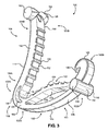
図1は、外科用結紮クリップ100の第1の実施形態の側面図である。図2及び図3は、クリップ100の斜視図である。クリップ100は、血管周りにラッチ止めされ、それにより血管を通る流体の流れを停止し又は減少させることができる止血クリップとして特に有用である。
FIG. 1 is a side view of the first embodiment of the
クリップ100は、近位端部分100A及び遠位端部分100Bを有するのが良い。クリップ100は、近位端部分102A及び遠位端部分102Bを備えた第1のレッグ部材102ならびに近位端部分104A及び遠位端部分104Bを備えた第2のレッグ部材104を更に有するのが良い。第1及び第2のレッグ部材102,104は、湾曲した部分を含む表面を有するのが良い。例えば、第1のレッグ部材102は、第1の内面108及び第1の外面110を有するのが良く、第2のレッグ部材104は、第2の内面112及び第2の外面114を有するのが良い。図1に示されているように、第1の内面108は、凸状の部分を有するのが良く、第1の外面110は、凸状の部分を有するのが良い。第2の内面112は、凸状の部分を有するのが良く、第2の外面114は、凹状の部分を有するのが良い。第1の内面108と第2の内面112は、クリップ100が当初止められたときに組織の近位部分をはさむよう構成されているのが良く、第1の内面108は、組織が結紮されているときに組織の幅に全体にわたって圧力を分布するようその長さに沿って弾性的に撓むことができるのが良い。
The
第1のレッグ部材102と第2のレッグ部材104は、ヒンジ部分106によって近位端部分102A,104Aのところで互いに接合されるのが良い。ヒンジ部分106は、弾性であるのが良くかつ/あるいはクリップ100と一体であるのが良い。ヒンジ部分106は、連続した凹状の内面116及び連続した凸状の外面118を有するのが良い。ヒンジ部分106の凹状内面116は、第1のレッグ部材102の第1の内面108と第2のレッグ部材104の第2の内面112を接合するのが良い。ヒンジ部分106の凸状外面118は、第1のレッグ部材102の第1の外面110と第2のレッグ部材104の第2の外面114を接合するのが良い。ヒンジ部分106は、湾曲したヒンジ表面116,118相互間に位置した湾曲スロット120を更に有するのが良く、このヒンジ部分は、凸状外面118よりも凹状内面116の方に近く位置決めされるのが良い。湾曲スロット120は、ヒンジ部分106を完全に貫通して側から側まで延びるのが良く、その反対側の端122,124は、それぞれ、第1及び第2のレッグ部材102,104の近位端部分102A,102B中に延びるのが良い。湾曲スロット120は、ヒンジ部分106に追加の可撓性及び弾性をもたらすことができるが、凹状内面116は、クランプされた血管の任意の部分が湾曲スロット120内に捕捉されるのを阻止することができる。
The
クリップ100は、第1及び第2のレッグ部材102,104に設けられたラッチ止め要素によって構成されるラッチ止め機構体を更に有するのが良い。例えば、第1のレッグ部材102は、湾曲したC字形フック区分126にその遠位端のところで移行するのが良い。第2のレッグ部材104は、尖った先端区分128までその遠位端のところで移行するのが良い。フック区分126の遠位部分は、内方に湾曲するとともに全体としてヒンジ部分106の凹状内面116の方へ向くのが良い。フック区分126は、1つ又は2つ以上の横断方向斜切面130及びラッチ止め部材又は凹部132を構成するよう第1の内面108と合体する凹状内面を有するのが良い。ラッチ止め凹部132は、クリップ100を血管又は端部組織周りのラッチ止め又は固定位置に押している間、先端区分128と合致した状態でこれに係合するのが良い。
The
レッグ部材102,104は、クリップアプライアに係合するようこれらの長さに沿って1つ又は2つ以上のボスを有するのが良い。例えば、第1のレッグ部材102の遠位端部分120Bに隣接して互いに反対側の側面138,140の各々に垂直にかつフック区分126のすぐ内方に突き出た円筒形ボス146,148(図2及び図3に示されている)を有するのが良い。クリップ100の図示の実施例では、ブリッジ区分150がボス146,148を互いに結合するのが良く、ボス146,148は、第1のレッグ部材102の第1の外面110を越えて外方に突き出るのが良い。第2のレッグ部材104もまた、その遠位端部分104Bのところに円筒形ボス152,154を更に有するのが良く、これら円筒形ボスは、第2のレッグ部材104の互いに反対側の側面142,144の各々に垂直に突き出るとともに先端区分128の先端を越えて前方に長手方向に延びている。血管を結紮する手技の際、クリップ100は、適当なクリップアプライア、例えば米国特許第5,100,416号明細書に記載されている形式のクリップアプライアの使用により血管周りのラッチ止め又はロック位置に押されるよう設計されているのが良く、この米国特許を参照により引用し、その開示内容全体を本明細書の一部とする。クリップアプライアは、クリップ100のボス146,148,152,154に係合してこれらをヒンジ部分106回りに内方に回動させることができる。
The
第1のレッグ部材102は、第1のレッグ部材102の第1の部分166及び第2の部分168のところで互いに接合された内側部分162と外側部分164を有するのが良い。内側部分162は、第1のレッグ部材102の内側から見て凸状の部分を有するのが良く、この凸状の部分は、凸状であるのが良い内面170及び凹状であるのが良い外面172を有する。外側部分164は、第1のレッグ部材102の内側から見て凹状の部分を有するのが良く、この凹状の部分は、凹状であるのが良い内面174及び凸状であるのが良い外面176を有する。内側部分162及び/又は外側部分164は、多くの互いに異なる曲率を有するのが良いことが想定される。例えば、内側部分162は、1つ又は2つ以上の凹状の、凸状の、及び/又は平坦な内面ならびに1つ又は2つ以上の凹状の、凸状の、及び/又は平坦な外面を有することができる。外側部分164は、1つ又は2つ以上の凹状の、凸状の、及び/又は平坦な内面ならびに1つ又は2つ以上の凹状の、凸状の、及び/又は平坦な外面を有するのが良い。
The
内側部分162の内面170は、第1の内面108の少なくとも一部分を構成するのが良く、外側部分164の外面176は、クリップ100の第1の外面110の少なくとも一部分を構成するのが良い。例えば、幾つかの実施形態では、内側部分162及び外側部分164は、第1のレッグ部材102の長さの半分を超えて(例えば、表面108,110の半分を超える長さを定める)延びるのが良い。幾つかの実施形態では、内側部分162及び外側部分164は、第1のレッグ部材102の長さの3/4を超えて(例えば、表面108,110の3/4を超える長さを定める)延びるのが良い。内側部分162及び外側部分164の各々は、第2のレッグ部材104の厚さよりも小さい厚さを有するのが良い。例えば、内側部分162及び/又は外側部分164の各々の厚さは、第1のレッグ部材102及び第2のレッグ部材104の各々の厚さの実質的半分であるのが良い。内側部分162の厚さの減少により、クリップ100によって圧迫される組織の形状に一致するための所望の可撓性が得られる。内側部分162、外側部分164及び第2のレッグ部材104は、横断方向に見て実質的に同一の幅を有するのが良い。
The
内側部分162と外側部分164は、第1のレッグ部材102の押し縮みを可能にするようクリップ100に沿って長手方向に延びる少なくとも1つの孔又はチャネル178によって互いに隔てられているのが良い。チャネル178は、第1のレッグ部材102の側面138,140相互間に延びるのが良い。例えば、組織をクリップ100内に効果的に掴むとともに保持しながら、チャネル178により、内側部分162は、外側部分164に向かって弾性的に押し縮めるとともに組織の長さに沿って荷重を分布させることができる。幾つかの実施形態では、チャネル178は、第1のレッグ部材の長さの半分を超えて長手方向に延びるのが良い。幾つかの実施形態では、チャネル178は、図1に示されているように第1のレッグ部材102の長さの3/4を超えて長手方向に延びるのが良い。外側部分164が凹状になっていることにより、内側部分162の弾性偏向を可能にする追加の余地が得られ、それによりクリップ100は、様々な形状、寸法、及び/又はスチフネスの組織を結紮するとともにこれに圧力を適正に分布させることができる。例えば、内側部分162は、組織が壊死して縮んでいるときであっても、ラッチ止めにおいて組織に連続した結紮圧力をもたらすことができる。幾つかの実施形態では、1つ又は2つ以上のリブが所望時に第1のレッグ部材102にスチフネスを提供するよう内側部分162と外側部分164との間に延びるのが良い。
The
図1〜図3の実施形態に更に示されているように、クリップ100は、第1の内面104上で突き出た第1の複数の歯134及び第2の内面114上で突き出た第2の複数の歯136を有するのが良い。歯134,136は、組織の圧迫の確実さを最大にすることができるとともに移動を最小限に抑えることができる。歯134,136は、第1及び第2のレッグ部材102,104の幅にわたって延びるのが良くかつクリップ100の近位端部分102Aに向かって傾けられるのが良い。幾つかの実施形態では、歯134,136は、近位端部分100Aに向かう組織の初期はさみ及び引きを助けるとともに更に圧迫され又は結紮されたときに組織の保持又は掴みを助けることができる。また、歯134,136により、クリップ100は、クリップが少なくとも部分的に開いているときに組織を操作することができる。幾つかの実施形態では、歯134,136は、省かれても良い。幾つかの実施形態では、米国特許仮出願第62/523,562号明細書に開示されているように歯134,136のうちの1つ又は2つ以上は、「外付け」形態のものであるのが良く(例えば、側面136〜142のうちの1つ又は2つ以上から延びている)、この米国特許仮出願を引用し、この記載内容全体を本明細書の一部とする。
As further shown in the embodiments of FIGS. 1 to 3, the
図4A〜図4Dは、組織500(例えば、血管)に止められている図1のクリップ100の一連の形態を示している。図4A〜図4Dに示されている形態のうちの1つ又は2つ以上は、組織500を圧迫するとともに/あるいは操作する(例えば、血管を一時的に又は永続的に結紮する)方法の1つ又は2つ以上のステップを提供することができる。
4A-4D show a series of forms of
図4Aに示されているように、組織500をクリップ100が開き形態にあるとき、第1のレッグ部材102と第2のレッグ部材104との間に位置決めするのが良い。図4Bに更に示されているように、クリップ100を当初押し縮めて組織500の近位部分をヒンジ部分106の近くに位置する内面108,112相互間ではさむのが良く、それによりクリップ100が閉じているときに組織500が遠位端部分100Bから滑り抜けること(例えば、「ウォーターメロン・シーディング」効果)を阻止する。また、組織500の初期はさみにより、外科医は、図4Bに例示的に示されているように少なくとも部分的に開かれている状態でクリップ100で組織500を操作することができる。例えば、組織500が他の身体構造の近位側に位置している場合、外科医は、組織500をはさみ(又は圧迫し)、そしてこれをレトラクトして他の構造から離し、それにより他の構造が結紮を妨害するのを阻止とともに/あるいはラッチ止め機構体が他の組織を損傷するのを阻止することができる。組織500の初期はさみは、閉じに先立って組織500をスケルトン化するのを更に助けることができる。
As shown in FIG. 4A, it is preferable to position the
図4Cに示されているように、組織500を第1及び第2のレッグ部材102,104によって更に圧迫するのが良い。幾つかの実施形態では、内面108,112及び歯134,136は、組織500を更にはさんでこれをヒンジ部分106に向かって引くのが良い。組織500のはさみ及び引きにより、組織500の確実さを高めることができるとともに「ウォーターメロン・シーディング」効果の潜在的発生を一段と減少させることができる。例えば、第2のレッグ部材104は、内面170に沿ってヒンジ部分106に向かって滑ることによって組織500を近位側の方向に引くことができ、またこの逆の関係が成り立つ。第2のレッグ部材104の近位側への滑りは、第1の内面108及び第2の内面112の各々が凸状になっていることの相互作用によって提供できる。例えば、第2の内面112は、内側部分162の内面170の近位部分に接触することができ(直接的にか組織を介してかのいずれかの状態で)、それにより第2のレッグ部材104及び/又は組織500がヒンジ部分106に向かって近位側に滑る。第2のレッグ部材104の近位側への滑りは、追加的に又は代替的に、第1のレッグ部材102の先端区分128と第2のレッグ部材104のフック区分126の当接によって提供できる。例えば、フック区分126の近位傾斜面上への先端区分128の当接により、第1のレッグ部材102は、第2のレッグ部材104に対して伸長し、第2のレッグ部材104は、組織500をヒンジ部分106に向かって引く。クリップ100を押し縮めることにより、組織500をクリップ100の近位端部分100Aから遠位端部分100Bに徐々に結紮することができる。
As shown in FIG. 4C, the
クリップ100を押し縮めることにより、内側部分162が外側部分164に向かって更に弾性的に偏向することができ、それにより圧力を組織500の幅に沿って分布させる。例えば、内側部分162は、組織500の寸法に適合することができ、組織500の幅全体に沿ってばね状の弾性圧力を加えることができ、かつ/あるいは潜在的な応力集中を減少させることができる。外側部分164もまた、クリップ100が押し縮められているときに伸長することができる。図4Dに更に示されているように、クリップ100は、例えばラッチ機構体により組織500を結紮形態に固定することができる。内側部分162は、組織500が壊死して縮んでいるときであっても、ラッチ止め形態によって組織500に連続結紮圧力をもたらすことができる。
By compressing the
図5A及び図5Bに更に示されているように、クリップ100は、組織がクリップ100の中の中央に配置されていない場合であっても、望ましい圧力分布を組織の互いに異なる形式及び寸法にもたらすよう構成されるのが良い。例えば、クリップ100は、実質的に硬い組織510(図5Aに示されている)又は実質的に柔軟性の組織520(図5Bに示されている)に適正な圧力分布をもたらすのが良い。例えば、組織510は、圧迫負荷に適合することができないので圧迫されている場合、応力集中を受ける場合のある過剰に応力が加えられ、線維化したかつ/あるいは壊死した組織であって良い。クリップ100は、内側部分162の偏向により組織500の結果としての応力集中を減少させることができる。内側部分162は、チャネル178中に弾性的に偏向することができ、組織510,520の形状に一致することができ、更に過剰な圧迫を阻止することができる。柔軟性組織520に適用されると、内側部分162は、減少した偏向の程度をもたらすことができる。さらに、内側部分の可撓性により、組織の束、例えば複数のリンパ節の結紮を促進することができる。内側部分の可撓性により、この内側部分が束の中の種々の組織の形状に合致することができ、他方、十分な圧力が束の中の組織の各々を結紮するよう加えられるようにする。
As further shown in FIGS. 5A and 5B, the
内側部分162はまた、その長さの任意の部分に沿って偏向することができる。例えば、組織510,520がヒンジ部分106の近くに位置決めされた場合、内側部分162の近位部分は、組織510,520に対応するよう偏向することができる。他方、組織510,520がラッチ止め機構体の近くに位置決めされた場合、内側部分162の遠位部分は、組織510,520に対応するよう偏向することができる。その意味において、クリップ100は、組織510,520がラッチ止め機構体かヒンジ部分106かのいずれかの近くに位置していることにより応力集中を減少させることができる。
The
クリップ100は更に、不規則な形状を持つ組織束(例えば、組織、血管、腺、リンパ節、及び神経)に適用できる。例えば、前立腺切除術中における背静脈コンプレックス(DVC)を結紮する際、各血管をクランプするようにすることが困難な場合がある。しかしながら、内側部分162は、DVCの血管の各々と個別的に同形となることができ、それにより適当な結紮圧力が各血管、組織構造又はリンパ節に加えられるようにすることができる。
図6は、外科用結紮クリップ200の第2の実施形態の側面図である。図7及び図8は、クリップ200の斜視図である。
FIG. 6 is a side view of the second embodiment of the
クリップ200は、近位端部分200A及び遠位端部分200Bを有するのが良い。クリップ200は、近位端部分202A及び遠位端部分202Bを備えた第1のレッグ部材202ならびに近位端部分204A及び遠位端部分204Bを備えた第2のレッグ部材204を更に有するのが良い。第1及び第2のレッグ部材202,204は、湾曲した部分を含む表面を有するのが良い。例えば、第1のレッグ部材202は、第1の内面208及び第1の外面210を有するのが良く、第2のレッグ部材204は、第2の内面212及び第2の外面214を有するのが良い。図6〜図8に示されているように、第1の内面208は、凸状の部分を有するのが良く、第2の外面210は、凸状の部分を有するのが良い。第2の内面212は、凸状の部分を有するのが良く、第2の外面214は、凸状の部分を有するのが良い。
The
第1のレッグ部材202と第2のレッグ部材204は、ヒンジ部分206によって近位端部分202A,204Aのところで互いに接合されるのが良い。ヒンジ部分206は、弾性であるのが良くかつ/あるいはクリップ200と一体であるのが良い。クリップ200は、第1及び第2のレッグ部材202,204に設けられたラッチ止め要素によって形成されるラッチ止め機構体を更に有するのが良い。例えば、第1のレッグ部材202は、湾曲したC字形フック226にその遠位端のところで移行するのが良い。レッグ部材202,204は、クリップアプライアに係合するようこれら長さに沿って1つ又は2つ以上のボスを更に有するのが良い。クリップ200は、例えば、図1〜図3に示されているように、第1の内面204上で突き出た第1の複数の歯(図示せず)及び第2の内面212上で突き出た第2の複数の歯(図示せず)を有するのが良い。
The
第2のレッグ部材202は、第1のレッグ部材202の第1の部分226及び第2の部分268のところで互いに接合された内側部分262と外側部分264を有するのが良い。内側部分262は、第1のレッグ部材202の内側から見て凸状の部分を有するのが良く、この凸状の部分は、凸状であるのが良い内面270及び凹状であるのが良い外面272を有する。外側部分264は、第1のレッグ部材202の内側から見て凹状の部分を有するのが良く、この凹状の部分は、凹状であるのが良い内面274及び凸状であるのが良い外面276を有する。内側部分262及び/又は外側部分264は、多くの互いに異なる曲率を有するのが良いことが想定される。例えば、内側部分262は、1つ又は2つ以上の凹状の、凸状の、及び/又は平坦な内面ならびに1つ又は2つ以上の凹状の、凸状の、及び/又は平坦な外面を有することができる。外側部分264は、1つ又は2つ以上の凹状の、凸状の、及び/又は平坦な内面ならびに1つ又は2つ以上の凹状の、凸状の、及び/又は平坦な外面を有するのが良い。
The
内側部分262の内面270は、第1の内面208の少なくとも一部分を構成するのが良く、外側部分264の外面276は、クリップ200の第1の外面210の少なくとも一部分を構成するのが良い。例えば、幾つかの実施形態では、内側部分262及び外側部分264は、第1のレッグ部材202の長さの半分を超えて(例えば、表面208,210の半分を超える長さを定める)延びるのが良い。幾つかの実施形態では、内側部分262及び外側部分264は、第1のレッグ部材202の長さの3/4を超えて(例えば、表面208,210の3/4を超える長さを定める)延びるのが良い。内側部分262及び外側部分264の各々は、第2のレッグ部材204の厚さよりも小さい厚さを有するのが良い。例えば、内側部分262及び/又は外側部分264の各々の厚さは、第1のレッグ部材202及び第2のレッグ部材204の各々の厚さの実質的半分であるのが良い。内側部分262の厚さの減少により、クリップ200によって圧迫される組織と形状が一致するための所望の可撓性が得られる。内側部分262、外側部分264及び第2のレッグ部材204は、横断方向に見て実質的に同一の幅を有するのが良い。
The
内側部分262と外側部分264は、第1のレッグ部材202の押し縮めを可能にするようクリップ200に沿って長手方向に延びる少なくとも1つの孔又はチャネル278によって互いに隔てられているのが良い。チャネル278は、第1のレッグ部材202の側面238,240相互間に延びるのが良い。例えば、組織をクリップ200内に効果的に掴むとともに保持しながら、チャネル278により、内側部分262は、外側部分264に向かって弾性的に押し縮めるとともに組織の長さに沿って荷重を分布させることができる。幾つかの実施形態では、チャネル278は、第1のレッグ部材202の長さの半分を超えて長手方向に延びるのが良い。幾つかの実施形態では、チャネル278は、図6に示されているように第1のレッグ部材202の長さの3/4を超えて長手方向に延びるのが良い。外側部分264が凹状になっていることにより、内側部分262の弾性偏向を可能にする追加の余地が得られ、それによりクリップ200は、様々な形状、寸法、及び/又はスチフネスの組織を結紮するとともにこれに圧力を適正に分布させることができる。例えば、内側部分262は、組織が壊死して縮んでいるときであっても、ラッチ止めにおいて組織に連続した結紮圧力をもたらすことができる。幾つかの実施形態では、1つ又は2つ以上のリブが所望時に第1のレッグ部材202にスチフネスを提供するよう内側部分262と外側部分264との間に延びるのが良い。
The
第2のレッグ部材204は、第1のレッグ部材204の第1の部分284及び第2の部分286のところで互いに接合された内側部分280と外側部分282を有するのが良い。内側部分280は、第2のレッグ部材204の内側から見て凸状の部分を有するのが良く、この凸状の部分は、凸状であるのが良い内面288及び凹状であるのが良い外面290を有する。外側部分282は、第1のレッグ部材202の内側から見て凹状の部分を有するのが良く、この凹状の部分は、凹状であるのが良い内面292及び凸状であるのが良い外面294を有する。内側部分280及び/又は外側部分282は、多くの互いに異なる曲率を有するのが良いことが想定される。例えば、内側部分280は、1つ又は2つ以上の凹状の、凸状の、及び/又は平坦な内面ならびに1つ又は2つ以上の凹状の、凸状の、及び/又は平坦な外面を有することができる。外側部分282は、1つ又は2つ以上の凹状の、凸状の、及び/又は平坦な内面ならびに1つ又は2つ以上の凹状の、凸状の、及び/又は平坦な外面を有するのが良い。
The
内側部分280の凸状内面288は、第2の内面212の少なくとも一部分を構成するのが良く、外側部分282の凸状外面294は、クリップ200の第2の外面214の少なくとも一部分を構成するのが良い。例えば、幾つかの実施形態では、内側部分280及び外側部分282は、第2のレッグ部材204の長さの半分を超えて(例えば、表面212,214の半分を超える長さを定める)延びるのが良い。幾つかの実施形態では、内側部分280及び外側部分282は、第2のレッグ部材204の長さの3/4を超えて(例えば、表面212,214の3/4を超える長さを定める)延びるのが良い。内側部分280及び外側部分282の各々は、クリップ200により圧迫される組織と同形となるよう所望の可撓性をもたらすために減少した厚さを有するのが良い。内側部分280は、外側部分282よりも横断方向で見て大きな幅を有するのが良い。
The convex
内側部分280と外側部分282は、第2のレッグ部材204の押し縮めを可能にするよう第2のレッグ部材204の側面242,244相互間に延びる少なくとも1つの孔又はチャネル296によって互いに隔てられているのが良い。例えば、組織をクリップ200内に効果的に掴むとともに保持しながら、チャネル296により、内側部分280は、外側部分282に向かって弾性的に押し縮めるとともに組織の長さに沿って荷重を分布させることができる。幾つかの実施形態では、チャネル296は、第2のレッグ部材204の長さの半分を超えて長手方向に延びるのが良い。幾つかの実施形態では、チャネル296は、図6に示されているように第2のレッグ部材204の長さの3/4を超えて長手方向に延びるのが良い。外側部分282が凹状になっていることにより、内側部分280の弾性偏向を可能にする追加の余地が得られ、それによりクリップ200は、様々な形状、寸法、及び/又はスチフネスの組織を結紮するとともにこれに圧力を適正に分布させることができる。例えば、内側部分280は、組織が壊死して縮んでいるときであっても、ラッチ止めにおいて組織に連続した結紮圧力をもたらすことができる。幾つかの実施形態では、1つ又は2つ以上のリブが所望時に第2のレッグ部材204にスチフネスを提供するよう内側部分280と外側部分282との間に延びるのが良い。
The
本明細書において用いられる「長手方向」という用語は、当業者には一般的に理解されているようにそれぞれの近位端部分からそれぞれの遠位端部分まで外科用クリップ100,200及び/又はレッグ部材102,104,202,204の長さに沿って延びる寸法方向を意味している。さらに、本明細書で用いられる「横断」方向は、例えば図1において図の平面に垂直である外科用クリップ100,200又はレッグ部材102,104,202,204の長手方向長さと直交する軸線又は方向を意味している。
The term "longitudinal" as used herein refers to
クリップ100,200は、任意適当なサイズのものであって良く、しかもかかるクリップを任意の種類の組織、例えば血管、リンパ節、神経、ファロピウス管、又は心組織に止めることができる。クリップ100,200は、任意適当な生体適合性材料、例えばある特定の金属及びポリマーで構成できる。しかしながら、本発明は、ポリマークリップを用いた手技に特に適している。かくして、クリップ100,200は、好ましくは、適当な強固な生体適合性エンジニアリングプラスチック、例えば外科用インプラントに通常用いられている形式のプラスチックで作られた一部品一体形ポリマー本体を有する。例示の材料としては、ホモポリマー又はコポリマーポリアセタール、ポリエチレンテレフタレート(PET)、ポリブチレンテレフタレート(PBT)、ポリオキシメチレン、又は同一の物品の状態に射出成形され、押出成形され又は違ったやり方で処理できる類似の特性を備えた他の熱可塑性材料が挙げられる。
本発明の多くの特徴及び多くの利点は、詳細な説明から明らかであり、かくして、本発明の精神及び範囲に属する本発明のかかる全ての特徴及び利点を含むことが特許請求の範囲の記載によって意図されている。さらに、多くの改造及び変形が当業者には容易に想到できるので、本発明を図示するとともに説明した構成及び作用そのものに限定することは望ましくなく、したがって、全ての適当な改造及び変形は、本発明の範囲に適用されてこの範囲に含まれる。 Many features and advantages of the present invention are apparent from the detailed description and thus include all such features and advantages of the present invention that belong to the spirit and scope of the invention by the claims. Intended. Moreover, it is not desirable to limit the present invention to the configurations and actions themselves illustrated and described, as many modifications and modifications can be readily conceived by those skilled in the art, and therefore all suitable modifications and modifications are made in this book. It is applied to the scope of the invention and is included in this scope.
100 外科用結紮クリップ
100A 近位端部分
100B 遠位端部分
102 第1のレッグ部材
102A 近位端部分
102B 遠位端部分
104 第2のレッグ部材
104A 近位端部分
104B 遠位端部分
106 ヒンジ部分
108 第1の内面
110 第1の外面
112 第2の内面
114 第2の外面
116 内面
118 外面
120 湾曲スロット
122 反対側の端
124 反対側の端
126 フック区分
128 先端区分
130 横断方向斜切面
132 凹部
134 第1の複数の歯
136 第2の複数の歯
138 側面
140 側面
142 側面
144 側面
146 ボス
148 ボス
150 ブリッジ区分
152 ボス
154 ボス
162 内側部分又は偏向内側部分
164 外側部分
166 第1の部分
168 第2の部分
170 内面
172 外面
174 内面
176 外面
178 孔又はチャネル
200 外科用結紮クリップ
200A 近位端部分
200B 遠位端部分
202 第1のレッグ部材
202A 近位端部分
202B 遠位端部分
204 第2のレッグ部材
204A 近位端部分
204B 遠位端部分
206 ヒンジ部分
208 第1の内面
210 第1の外面
212 第2の内面
214 第2の外面
216 内面
218 外面
220 湾曲スロット
222 反対側の端
224 反対側の端
226 C字形フック区分
228 先端区分
230 横断方向斜切面
232 凹部
238 側面
240 側面
242 側面
244 側面
246 ボス
248 ボス
250 ブリッジ区分
252 ボス
254 ボス
262 内側部分
264 外側部分
266 第1の部分
268 第2の部分
270 内面
272 外面
274 内面
276 外面
278 孔
280 内側部分
282 外側部分
284 第1の部分
286 第2の部分
288 内面
290 外面
292 内面
294 外面
296 孔
500 組織
510 硬組織
520 柔軟組織
100 Surgical ligation clip 100A Proximal end part 100B Distal end part 102 First leg member 102A Proximal end part 102B Distal end part 104 Second leg member 104A Proximal end part 104B Distal end part 106 Hing part 108 First inner surface 110 First outer surface 112 Second inner surface 114 Second outer surface 116 Inner surface 118 Outer surface 120 Curved slot 122 Opposite end 124 Opposite end 126 Hook division 128 Tip division 130 Transverse diagonal cut surface 132 Recess 134 First Multiple Teeth 136 Second Multiple Teeth 138 Side 140 Side 142 Side 144 Side 146 Boss 148 Boss 150 Bridge Division 152 Boss 154 Boss 162 Inner or Deflection Inner Part 164 Outer Part 166 First Part 168 First Part 2 170 Inner 172 Outer 174 Inner 176 Outer 178 Hole or Channel 200 Surgical ligation clip 200A Proximal end 200B Distal end 202 First leg member 202A Proximal end 202B Distal end 204 Second Leg member 204A Proximal end part 204B Distal end part 206 Hing part 208 First inner surface 210 First outer surface 212 Second inner surface 214 Second outer surface 216 Inner surface 218 Outer surface 220 Curved slot 222 Opposite end 224 Opposite side End 226 C-shaped hook division 228 Tip division 230 Transverse diagonal cut surface 232 Recess 238 Side 240 Side side 242 Side side 244 Side 246 Boss 248 Boss 250 Bridge division 252 Boss 254 Boss 262 Inner part 264 Outer part 266 First part 268 Second Part 270 Inner Surface 272 Outer Surface 274 Inner Surface 276 Outer Surface 278 Hole 280 Inner Part 282 Outer Part 284 First Part 286 Second Part 288 Inner Surface 290 Outer Surface 292 Inner Surface 294 Outer Surface 296 Holes 500 Tissue 510 Hard Tissue 520 Flexible Tissue
Claims (14)
近位端部分、遠位端部分、凸状の第1の内面、及び凸状の第1の外面を備えた第1のレッグ部材を有し、前記第1のレッグ部材は、前記第1の内面を少なくとも部分的に構成する第1の内側部分及び前記第1の外面を少なくとも部分的に構成する第1の外側部分を有し、前記第1の内側部分と前記第1の外側部分は、第1のチャネルによって互いに隔てられた状態で前記第1のレッグ部材の第1及び第2の部分のところで互いに接合され、
近位端部分、遠位端部分、第2の内面、及び第2の外面を備えた第2のレッグ部材を有し、前記第1のレッグ部材と前記第2のレッグ部材は、開き位置と閉じ位置との間で互いに対して動くことができ、前記第1の内面及び前記第2の内面は、前記閉じ位置にあるときに前記組織を結紮するよう構成されており、
前記第1の内側部分は、前記閉じ形態において弾性的に偏向されるよう構成されている、外科用クリップ。 A surgical clip configured to ligate tissue, said surgical clip.
It has a first leg member having a proximal end portion, a distal end portion, a convex first inner surface, and a convex first outer surface, wherein the first leg member is the first leg member. It has a first inner portion that at least partially constitutes an inner surface and a first outer portion that at least partially constitutes the first outer surface, and the first inner portion and the first outer portion are composed of the first inner portion and the first outer portion. They are joined to each other at the first and second portions of the first leg member, separated from each other by the first channel.
It has a second leg member having a proximal end portion, a distal end portion, a second inner surface, and a second outer surface, and the first leg member and the second leg member are in an open position. The first inner surface and the second inner surface are configured to ligate the tissue when in the closed position, allowing them to move relative to each other with and from the closed position.
The first medial portion is a surgical clip configured to be elastically deflected in said closed form.
前記第2の内面に設けられた少なくとも1つの第2の歯と、を更に有する、請求項1記載の外科用クリップ。 With at least one first tooth provided on the first inner surface,
The surgical clip according to claim 1, further comprising at least one second tooth provided on the second inner surface.
Applications Claiming Priority (3)
| Application Number | Priority Date | Filing Date | Title |
|---|---|---|---|
| US201662370502P | 2016-08-03 | 2016-08-03 | |
| US62/370,502 | 2016-08-03 | ||
| PCT/US2017/045298 WO2018027032A1 (en) | 2016-08-03 | 2017-08-03 | Surgical ligation clip |
Publications (2)
| Publication Number | Publication Date |
|---|---|
| JP2019524281A JP2019524281A (en) | 2019-09-05 |
| JP6837127B2 true JP6837127B2 (en) | 2021-03-03 |
Family
ID=61071888
Family Applications (1)
| Application Number | Title | Priority Date | Filing Date |
|---|---|---|---|
| JP2019506083A Active JP6837127B2 (en) | 2016-08-03 | 2017-08-03 | Surgical ligature clip |
Country Status (7)
| Country | Link |
|---|---|
| US (3) | US10548609B2 (en) |
| EP (1) | EP3493747A4 (en) |
| JP (1) | JP6837127B2 (en) |
| CN (1) | CN109788947B (en) |
| AU (1) | AU2017305440B2 (en) |
| CA (1) | CA3032824C (en) |
| WO (1) | WO2018027032A1 (en) |
Families Citing this family (39)
| Publication number | Priority date | Publication date | Assignee | Title |
|---|---|---|---|---|
| AU2017305440B2 (en) | 2016-08-03 | 2019-11-07 | Teleflex Medical Llc | Surgical ligation clip |
| CN116784923A (en) | 2017-03-21 | 2023-09-22 | 泰利福医疗公司 | Clip applier with stabilizing member |
| JP6876821B2 (en) | 2017-03-21 | 2021-05-26 | テレフレックス メディカル インコーポレイテッド | Clip applier with replaceable tip |
| JP7159189B2 (en) | 2017-03-21 | 2022-10-24 | テレフレックス メディカル インコーポレイテッド | Flexible stabilizing member for clip applier |
| JP6873267B2 (en) | 2017-03-21 | 2021-05-19 | テレフレックス メディカル インコーポレイテッド | Clip applier with stabilizer |
| CN119385632A (en) * | 2017-03-21 | 2025-02-07 | 泰利福医疗公司 | Surgical Clips and Clip Appliers |
| US12023041B2 (en) | 2017-03-21 | 2024-07-02 | Teleflex Medical Incorporated | Clip applier |
| EP3641667A4 (en) * | 2017-06-22 | 2021-03-10 | Teleflex Medical Incorporated | Surgical clip |
| USD838847S1 (en) * | 2017-10-20 | 2019-01-22 | Dahong Zhang | Hemostatic clamp |
| US20190133590A1 (en) * | 2017-11-03 | 2019-05-09 | Covidien Lp | Ligation clip with controlled tissue compression |
| CN117357190A (en) | 2017-11-14 | 2024-01-09 | 泰利福医疗公司 | Surgical clip |
| US10932788B2 (en) | 2018-04-11 | 2021-03-02 | Covidien Lp | Ligation clip with latching and retention features |
| US10932789B2 (en) | 2018-04-11 | 2021-03-02 | Covidien Lp | Ligation clip with latching and retention features |
| US11033279B2 (en) | 2018-04-24 | 2021-06-15 | Covidien Lp | Ligation clip with retention features |
| US12220119B2 (en) | 2018-05-22 | 2025-02-11 | Boston Scientific Scimed, Inc. | Tissue engagement device |
| KR102561698B1 (en) * | 2018-05-22 | 2023-07-28 | 보스톤 싸이엔티픽 싸이메드 인코포레이티드 | tissue engagement device |
| US11304703B2 (en) | 2018-05-25 | 2022-04-19 | Covidien Lp | Ligation clip removal device |
| KR102092347B1 (en) * | 2018-07-16 | 2020-03-23 | 주식회사 엔도비전 | Banana clip for removing hemorrhoids and Surgical tool set including the same |
| US11317923B2 (en) | 2018-08-13 | 2022-05-03 | Covidien Lp | Ligation clip with improved hinge |
| US11304704B2 (en) | 2018-08-22 | 2022-04-19 | Covidien Lp | Surgical clip applier and ligation clips |
| EP3856047A4 (en) | 2018-09-26 | 2022-06-22 | Teleflex Medical Incorporated | STAPLER APPLICATOR WITH STABILIZING ELEMENT |
| KR20250130719A (en) * | 2018-11-16 | 2025-09-02 | 텔리플렉스 메디컬 인코포레이티드 | Surgical clip |
| US11471165B2 (en) | 2019-05-08 | 2022-10-18 | Covidien Lp | Ligation clip cartridge |
| US11707282B2 (en) | 2019-07-02 | 2023-07-25 | Covidien Lp | Multi-piece ligation clip |
| USD907203S1 (en) | 2019-08-02 | 2021-01-05 | Covidien Lp | Ligation clip |
| USD907204S1 (en) | 2019-08-02 | 2021-01-05 | Covidien Lp | Ligation clip |
| USD907200S1 (en) | 2019-08-05 | 2021-01-05 | Covidien Lp | Ligation clip |
| US11395660B2 (en) | 2019-08-05 | 2022-07-26 | Covidien Lp | Stackable ligation clip |
| CN112546339A (en) * | 2019-09-10 | 2021-03-26 | 贝克顿·迪金森公司 | Blood vessel access system, blood collection method and clamping device |
| CN114727748B (en) | 2019-09-26 | 2026-01-13 | 泰利福医疗公司 | Clip applier |
| EP4076216A1 (en) | 2019-12-19 | 2022-10-26 | Teleflex Medical Incorporated | Surgical clip |
| US11696764B2 (en) * | 2020-01-31 | 2023-07-11 | Covidien Lp | Ligation clip with controlled tissue compression |
| WO2021193463A1 (en) * | 2020-03-24 | 2021-09-30 | 学校法人自治医科大学 | Medical instrument suitable for ligature or similar |
| US12114866B2 (en) | 2020-03-26 | 2024-10-15 | Covidien Lp | Interoperative clip loading device |
| EP4178465A4 (en) | 2020-07-08 | 2024-04-03 | A2 Medical Systems LLC | LIGATION CLIPS WITH ANTI-MIGRATION FEATURES |
| JP2024510273A (en) * | 2021-03-16 | 2024-03-06 | コヴィディエン リミテッド パートナーシップ | Ligation clip containing flexible insert assembly |
| US12453549B2 (en) | 2021-05-07 | 2025-10-28 | Teleflex Medical Incorporated | Device and method for unlatching a surgical clip |
| AU2022325511A1 (en) * | 2021-08-10 | 2024-02-29 | Sure Retractors Ltd | Retractors |
| CN114010253B (en) * | 2021-11-02 | 2023-07-07 | 苏州美东汇成精密部件有限公司 | An adjustable ligature clip |
Family Cites Families (159)
| Publication number | Priority date | Publication date | Assignee | Title |
|---|---|---|---|---|
| US1728322A (en) | 1928-02-22 | 1929-09-17 | Badrian Max | Device for elastically clamping off the male urethra |
| US3503397A (en) | 1967-09-21 | 1970-03-31 | American Hospital Supply Corp | Atraumatic surgical clamp |
| US3766925A (en) | 1971-05-25 | 1973-10-23 | Eljay Hospital Prod Corp | Surgical clamp with cam-action lever |
| US3867944A (en) | 1972-10-27 | 1975-02-25 | Wood Ernest C | Hemostatic clip and applicator therefor |
| US3874042A (en) | 1973-01-22 | 1975-04-01 | Biospectrum Inc | Clamp for thin walled tubing |
| US3825012A (en) | 1973-04-13 | 1974-07-23 | H Nicoll | Reusable umbilical cord clamp for veterinary use |
| US4337774A (en) | 1978-06-14 | 1982-07-06 | Metatech Corporation | Micro surgical clip |
| US4390019A (en) | 1979-02-28 | 1983-06-28 | Leveen Harry H | Blood vessel clamp |
| US4527562A (en) | 1979-06-18 | 1985-07-09 | Ethicon, Inc. | Non-metallic, bio-compatible hemostatic clips |
| CA1157335A (en) | 1979-06-18 | 1983-11-22 | Namassivaya Doddi | Plastic ligating clips |
| US4418694A (en) | 1979-06-18 | 1983-12-06 | Ethicon, Inc. | Non-metallic, bio-compatible hemostatic clips |
| MX151148A (en) | 1980-02-25 | 1984-10-04 | Johnson & Johnson | IMPROVEMENTS IN HEMOSTATIC FORCEPS |
| US4638804A (en) | 1980-02-25 | 1987-01-27 | Ethicon, Inc. | Double-latched non-metallic, bio-compatible hemostatic clip |
| US4345600A (en) | 1980-08-04 | 1982-08-24 | Senco Products, Inc. | Purse-stringer |
| US4346869A (en) | 1981-03-12 | 1982-08-31 | Macneill Robert L | Tube clamp |
| US4550729A (en) | 1981-08-27 | 1985-11-05 | Ethicon, Inc. | Non-metallic, bio-compatible hemostatic clips with interlocking latch means |
| US4476865A (en) | 1982-02-12 | 1984-10-16 | Ethicon, Inc. | Non-metallic, bio-compatible hemostatic clips |
| US4450840A (en) | 1982-02-26 | 1984-05-29 | Ethicon, Inc. | Ligating clip with flanged base having a recessed engaging face |
| US4487205A (en) | 1982-04-26 | 1984-12-11 | Ethicon, Inc. | Non-metallic, bio-compatible hemostatic clips |
| US4458682A (en) | 1982-08-02 | 1984-07-10 | Ethicon, Inc. | Non-metallic, bio-compatible hemostatic clips (ring lock clips) |
| US4519392A (en) | 1982-10-12 | 1985-05-28 | Lingua Robert W | Hemostasing muscle clips for needleless surgery |
| US4579118A (en) | 1983-06-01 | 1986-04-01 | Ethicon, Inc. | Hemostatic clip with penetration means |
| US5127915A (en) | 1984-10-29 | 1992-07-07 | Mattson Philip D | Surgical instrument for severing and clamping an umbilical cord |
| US4589626A (en) | 1985-03-13 | 1986-05-20 | Bioresearch Inc. | Hose clamp |
| US4588160A (en) | 1985-03-27 | 1986-05-13 | Sherwood Medical Company | Tube clamping device |
| JPH0657218B2 (en) | 1985-05-10 | 1994-08-03 | エチコン・インコ−ポレ−テツド | Ligation clip and clip application device |
| US5047038A (en) | 1985-07-01 | 1991-09-10 | Edward Weck Incorporated | Automatic hemostatic clip applier |
| US4712549A (en) | 1985-07-01 | 1987-12-15 | Edward Weck & Co. | Automatic hemostatic clip applier |
| US4807622A (en) | 1985-09-20 | 1989-02-28 | Kato Hatsujo Kaisha, Ltd. | Tube cutting and separating implement for conduit of blood or the like |
| US4716886A (en) | 1986-05-01 | 1988-01-05 | Norman Schulman | Umbilical cord clamp and cutters |
| US4726372A (en) | 1986-09-19 | 1988-02-23 | Metatech Corporation | Hemostatic clip |
| US4822348A (en) | 1987-05-13 | 1989-04-18 | Donn Casey | Surgical clips |
| US4834096A (en) | 1987-10-26 | 1989-05-30 | Edward Weck Incorporated | Plastic ligating clips |
| GB2212201B (en) | 1987-11-10 | 1992-06-03 | Donn Casey | Surgical clip |
| US4870965A (en) | 1988-03-04 | 1989-10-03 | Jahanger Mohammed S | Umbilical cord cutting and clamping device |
| US4942886A (en) | 1989-02-22 | 1990-07-24 | Timmons John W | External incontinency device |
| US5062846A (en) | 1989-03-28 | 1991-11-05 | Edward Weck Incorporated | Penetrating plastic ligating clip |
| US4976722A (en) | 1989-05-22 | 1990-12-11 | Ethicon, Inc. | Surgical hemostatic clips |
| US4938765A (en) | 1989-06-22 | 1990-07-03 | Life Centers, Inc. | Surgical silicon loops |
| US5104395A (en) | 1989-07-03 | 1992-04-14 | Edward Weck Incorporated | Automatic hemostatic clip applicator |
| US4950275A (en) | 1989-07-19 | 1990-08-21 | Cyanamid Italia S.P.A. | Bowel-anastomosis-ring holder pincers |
| US4972949A (en) | 1989-09-26 | 1990-11-27 | Horizon Surgical, Inc. | Hemostatic clip holder for small clips |
| US4936447A (en) | 1989-09-26 | 1990-06-26 | Horizon Surgical Inc. | Hemostatic clip holder |
| US5100416A (en) | 1989-10-17 | 1992-03-31 | Edward Weck Incorporated | Ligating clip applying instrument |
| US5009657A (en) | 1989-12-14 | 1991-04-23 | Mohammed S. Jahanger | Umbilical cord cutting and clamping device |
| US4961499A (en) | 1990-01-04 | 1990-10-09 | Pilling Co. | Hemostatic clip cartridge |
| US5078731A (en) | 1990-06-05 | 1992-01-07 | Hayhurst John O | Suture clip |
| US5026382A (en) | 1990-08-27 | 1991-06-25 | Horizon Surgical, Inc. | Hemostatic clip |
| US5046611A (en) | 1990-10-22 | 1991-09-10 | Edward Weck Incorporated | Hemostatic clip cartridge |
| US5201416A (en) | 1990-10-22 | 1993-04-13 | Edward Weck Incorporated | Hemostatic clip cartridge |
| US5366458A (en) | 1990-12-13 | 1994-11-22 | United States Surgical Corporation | Latchless surgical clip |
| US5171252A (en) | 1991-02-05 | 1992-12-15 | Friedland Thomas W | Surgical fastening clip formed of a shape memory alloy, a method of making such a clip and a method of using such a clip |
| US5112343A (en) | 1991-04-05 | 1992-05-12 | Edward Weck Incorporated | Endoscopic clip appliers |
| US5160339A (en) | 1991-06-18 | 1992-11-03 | Ethicon, Inc. | Endoscopic suture clip |
| US5259405A (en) | 1992-01-29 | 1993-11-09 | Hua Chou Kuo | Structure of a barette |
| US5171251A (en) | 1992-03-02 | 1992-12-15 | Ethicon, Inc. | Surgical clip having hole therein and method of anchoring suture |
| US5279416A (en) | 1992-06-05 | 1994-01-18 | Edward Weck Incorporated | Ligating device cartridge with separable retainer |
| US5234449A (en) | 1992-07-16 | 1993-08-10 | Ethicon, Inc. | Suture clip with reduced hinge mass |
| US5330442A (en) | 1992-10-09 | 1994-07-19 | United States Surgical Corporation | Suture retaining clip |
| US5330487A (en) | 1992-12-17 | 1994-07-19 | Tfi Acquistion Corp. | Drive mechanism for surgical instruments |
| CA2120828C (en) | 1993-04-16 | 1999-11-02 | Paul J. Phillips | Surgical hemostatic clip |
| US5549621A (en) | 1993-05-14 | 1996-08-27 | Byron C. Sutherland | Apparatus and method for performing vertical banded gastroplasty |
| DK110193A (en) | 1993-09-30 | 1995-03-31 | Per Baunsgaard | Terminal device |
| US5462555A (en) | 1993-12-30 | 1995-10-31 | United States Surgical Corporation | Umbilical cord clip and applicator |
| GB9400739D0 (en) | 1994-01-15 | 1994-03-16 | Femcare Ltd | Medical clip |
| US5501693A (en) | 1994-07-06 | 1996-03-26 | United States Surgical Corporation | Surgical hemostatic clip |
| US5487746A (en) | 1994-11-23 | 1996-01-30 | Yu; George W. | Surgical clip having a longitudinal opening through which clamped tissue protrudes |
| US5695505A (en) | 1995-03-09 | 1997-12-09 | Yoon; Inbae | Multifunctional spring clips and cartridges and applicators therefor |
| US5667516A (en) | 1995-05-01 | 1997-09-16 | Allen; Sean A. | Mechanism for cutting an umbilical cord |
| US5908430A (en) | 1995-06-07 | 1999-06-01 | Appleby; Timothy | Easy loading hemostatic clip and cartridge |
| US5713912A (en) | 1995-08-30 | 1998-02-03 | Stress Management, Inc. | Ligating clip having ramp-shaped vessel clamping members and tool for applying same |
| JP3178648B2 (en) | 1995-12-28 | 2001-06-25 | 住友金属工業株式会社 | Protective film coating equipment for semiconductor substrates |
| US5810853A (en) | 1996-01-16 | 1998-09-22 | Yoon; Inbae | Knotting element for use in suturing anatomical tissue and methods therefor |
| US6015417A (en) | 1996-01-25 | 2000-01-18 | Reynolds, Jr.; Walker | Surgical fastener |
| US5846255A (en) | 1996-01-31 | 1998-12-08 | Casey Medical Products Limited | Surgical clip |
| US5925052A (en) | 1996-06-26 | 1999-07-20 | Simmons; Paul L. | Umbilical surgical scissors |
| US5722982A (en) | 1996-09-26 | 1998-03-03 | University Technology Corporation | Strabismus surgery apparatus and method |
| US5713911A (en) | 1996-10-03 | 1998-02-03 | United States Surgical Corporation | Surgical clip |
| US5921991A (en) | 1997-10-23 | 1999-07-13 | Biomax Technologies Inc. | Multi-colored umbilical cord clamp |
| US6131576A (en) | 1998-03-23 | 2000-10-17 | Davis; Paul K. | Male incontinence clamp, kit and method of use |
| US5997548A (en) | 1998-07-22 | 1999-12-07 | Jahanger; Mohammed S. | Umbilical cord cutting and clamping device |
| US6099539A (en) | 1998-07-27 | 2000-08-08 | Thomas J. Fogarty | Surgical clamp pad with interdigitating teeth |
| DE19858581C2 (en) | 1998-12-18 | 2001-03-08 | Aesculap Ag & Co Kg | Vascular clip |
| US6210419B1 (en) | 1998-12-18 | 2001-04-03 | Aesculap Ag & Co. Kg | Surgical clip |
| US6217590B1 (en) | 1999-01-22 | 2001-04-17 | Scion International, Inc. | Surgical instrument for applying multiple staples and cutting blood vessels and organic structures and method therefor |
| GB2353710A (en) * | 1999-08-06 | 2001-03-07 | Henleys Medical Supplies Ltd | Umbilical cord clamp |
| IL132913A (en) | 1999-11-14 | 2004-09-27 | Porat Michael | Device and method for clamping and cutting a flexible deformable tube |
| GB9927040D0 (en) | 1999-11-17 | 2000-01-12 | Femcare Ltd | Medical clips |
| US6695854B1 (en) | 1999-11-29 | 2004-02-24 | General Surgical Innovations, Inc. | Blood vessel clip and applicator |
| US7963964B2 (en) | 2000-02-10 | 2011-06-21 | Santilli Albert N | Surgical clamp assembly with electrodes |
| US6391035B1 (en) | 2000-03-24 | 2002-05-21 | Timothy Appleby | Hemostatic clip removal instrument |
| US6419682B1 (en) | 2000-03-24 | 2002-07-16 | Timothy Appleby | Hemostatic clip cartridge |
| US6349727B1 (en) | 2000-05-25 | 2002-02-26 | Pos-T-Vac, Inc. | Penile clamp for inhibiting incontinence |
| US6719766B1 (en) | 2000-08-24 | 2004-04-13 | Novare Surgical Systems, Inc. | Surgical clamp pads having surface overlay |
| US7232445B2 (en) | 2000-12-06 | 2007-06-19 | Id, Llc | Apparatus for the endoluminal treatment of gastroesophageal reflux disease (GERD) |
| US6981505B2 (en) | 2001-02-13 | 2006-01-03 | Krause William R | Urological device for the incontinent male |
| JP2002345828A (en) | 2001-05-23 | 2002-12-03 | Asahi Optical Co Ltd | Endoscope clip device |
| US6824547B2 (en) | 2001-07-13 | 2004-11-30 | Pilling Weck Incorporated | Endoscopic clip applier and method |
| AUPR668901A0 (en) | 2001-07-31 | 2001-08-23 | Research Surgical Pty Ltd | Surgical clamps |
| US7338503B2 (en) | 2002-08-08 | 2008-03-04 | Interrad Medical, Inc. | Non-invasive surgical ligation clip system and method of using |
| US6638282B2 (en) | 2001-10-16 | 2003-10-28 | Cetus, Lc | Umbilical cord cutting and clamping device |
| US20050149069A1 (en) | 2001-12-04 | 2005-07-07 | Bertolero Arthur A. | Left atrial appendage devices and methods |
| US8262639B2 (en) | 2002-01-31 | 2012-09-11 | Fenwal, Inc. | Irreversible flow control clamp |
| US7211091B2 (en) | 2002-08-27 | 2007-05-01 | Pilling Weck Incorporated | Fingertip-actuated surgical clip applier and related methods |
| US6880699B2 (en) | 2002-08-27 | 2005-04-19 | Pilling Weck Incorporated | Cartridge for holding asymmetric surgical clips |
| US7131977B2 (en) | 2002-08-27 | 2006-11-07 | Pilling Weck Incorporated | Apparatus and method for removing a clip |
| US6863675B2 (en) | 2002-09-20 | 2005-03-08 | Pilling Weck Incorporated | Ligating clip with integral penetrating hook |
| ATE540607T1 (en) * | 2002-11-08 | 2012-01-15 | Maternus Partners Ltd | UMBILICAL CORD CLAMP AND CUTTER |
| US7052504B2 (en) | 2002-11-19 | 2006-05-30 | Teleflex Incorporated | Automated-feed surgical clip applier and related methods |
| US7211092B2 (en) | 2002-11-19 | 2007-05-01 | Pilling Weck Incorporated | Automated-feed surgical clip applier and related methods |
| US6843253B2 (en) | 2002-12-11 | 2005-01-18 | C&L Medical Supply Corporation | Urinary-control device |
| US7107995B2 (en) * | 2002-12-11 | 2006-09-19 | C&L Medical Supply Corporation | Urinary-control device |
| US7316696B2 (en) | 2004-01-22 | 2008-01-08 | Teleflex Medical Incorporated | Ligating clip with integral interlocking latch mechanism |
| US7326223B2 (en) | 2004-01-22 | 2008-02-05 | Teleflex Medical Incorporated | Ligating clip with integral cutting guide |
| US20050165429A1 (en) | 2004-01-23 | 2005-07-28 | Peter Douglas | Surgical clamp possessing a combined parallel and scissor style clamp head |
| US20050165423A1 (en) | 2004-01-23 | 2005-07-28 | Pilling Weck Incorporated | Ligating clip with integral tissue-securing mechanism |
| US7001412B2 (en) * | 2004-01-28 | 2006-02-21 | Pilling Weck Incorporated | Surgical clip with integral suture-securing mechanism |
| US7585304B2 (en) | 2004-02-02 | 2009-09-08 | Teleflex Medical Incorporated | Endoscopic clip applying apparatus with improved aperture for clip release and related method |
| US7645285B2 (en) | 2004-05-26 | 2010-01-12 | Idx Medical, Ltd | Apparatus and methods for occluding a hollow anatomical structure |
| BRMU8401529U (en) | 2004-07-02 | 2006-02-21 | Milton Tatsuo Tanaka | laparoscopic curved surgical clip |
| US20060217749A1 (en) | 2005-03-24 | 2006-09-28 | Pilling Weck Incorporated | Reduced closure force ligating clip |
| EP1876971A1 (en) | 2005-03-24 | 2008-01-16 | Pilling Weck Incorporated | Reduced closure force ligating clip |
| AU2006267056C1 (en) | 2005-07-14 | 2013-03-28 | Atricure, Inc. | Apparatus and methods for occluding a hollow anatomical structure |
| US20070083218A1 (en) | 2005-10-12 | 2007-04-12 | A Morris Steven | Coated ligating clip |
| US20070118161A1 (en) | 2005-11-22 | 2007-05-24 | Kennedy Daniel L | Non-snag polymer ligating clip |
| US9480480B2 (en) | 2005-12-22 | 2016-11-01 | Albert N. Santilli | Vascular and intestinal occlusion |
| DE202006000329U1 (en) | 2006-01-11 | 2006-03-02 | Aesculap Ag & Co. Kg | Surgical ligature clip |
| US7635374B2 (en) | 2006-03-09 | 2009-12-22 | Niti Surgical Solutions Ltd. | Endoscopic full thickness resection using surgical compression clips |
| EP2015681B1 (en) | 2006-05-03 | 2018-03-28 | Datascope Corp. | Tissue closure device |
| US20080287976A1 (en) | 2007-05-14 | 2008-11-20 | Weaner Lauren S | Gastric band with engagement member |
| US8118826B2 (en) | 2007-09-27 | 2012-02-21 | Swan Valley Medical, Incorporated | Method of performing a suprapubic transurethral cystostomy and associated procedures and apparatus therefor |
| US9445820B2 (en) | 2007-12-31 | 2016-09-20 | Teleflex Medical Incorporated | Ligation clip with flexible clamping feature |
| US8366726B2 (en) | 2008-03-21 | 2013-02-05 | Gyrx Llc | Vessel occlusion clip and application thereof |
| US20100114131A1 (en) | 2008-11-05 | 2010-05-06 | Adam Rotunda | Skin tag removal system |
| GB2465560A (en) | 2008-11-19 | 2010-05-26 | Frank Vinzenz Benedikt | Absorbable veterinary sterilisation clamp |
| US8795328B2 (en) | 2009-01-08 | 2014-08-05 | Coherex Medical, Inc. | Medical device for modification of left atrial appendage and related systems and methods |
| US20100211080A1 (en) | 2009-02-13 | 2010-08-19 | Dean Trivisani | Umbiliguard |
| CN101507646B (en) * | 2009-03-26 | 2012-08-22 | 杭州康基医疗器械有限公司 | Vascular clamp die |
| US20100274268A1 (en) | 2009-04-24 | 2010-10-28 | Singh Errol O | Squeeze-to-set medical clamp |
| CN101543418B (en) | 2009-04-30 | 2011-01-05 | 何定甫 | Single-side umbilical clamp |
| US20110295291A1 (en) | 2010-05-28 | 2011-12-01 | Dean Trivisani | Novel Vascular Clamp |
| US10335157B2 (en) | 2010-10-02 | 2019-07-02 | Covidien Lp | Asymmetrical surgical clip with penetrating lock, non-slip clamping surface, severable hinge, hinge boss and pivoting applicator tip |
| RU2485908C2 (en) | 2010-12-07 | 2013-06-27 | Компания с ограниченной ответственностью Глобитек 2000 | Method of creating hemostasis with possibility of blood flow recovery in tubular elastic structures of organism and devices for its realisation |
| CN102028517A (en) | 2011-01-21 | 2011-04-27 | 常州市三联星海医疗器械制造有限公司 | Tissue clamp |
| CA2830073A1 (en) | 2011-03-21 | 2012-09-27 | The Administrators Of The Tulane Educational Fund | Multi-component detachable jaw tools and methods of using and making same |
| US9039737B2 (en) | 2011-03-29 | 2015-05-26 | Ocunetics, Inc. | Fasteners, deployment systems, and methods for ophthalmic tissue closure and fixation of ophthalmic prostheses and other uses |
| JP5848827B2 (en) * | 2011-09-15 | 2016-01-27 | テレフレックス メディカル インコーポレイテッドTeleflex Medical Incorporated | Manual surgical ligation clip applier |
| JP6754169B2 (en) | 2011-10-20 | 2020-09-09 | テレフレックス ライフ サイエンシーズ アンリミテッド カンパニー | Ligature clip |
| US9084596B2 (en) | 2012-02-27 | 2015-07-21 | Cook Medical Technologies Llc | Suture clamp and gastrointestinal suture anchor set device using same |
| EP2819595A1 (en) * | 2012-02-28 | 2015-01-07 | Boston Scientific Scimed, Inc. | Clip applier |
| US9282972B1 (en) * | 2012-10-14 | 2016-03-15 | Innovative Urololy, Llc | Surgical clips with penetrating locking mechanism and non-slip clamping surfaces |
| US9220507B1 (en) | 2012-10-14 | 2015-12-29 | Manoj B. Patel | Tissue spreading vascular clips with locking mechanism and non-slip clamping surfaces |
| CN103919589A (en) * | 2014-03-10 | 2014-07-16 | 浙江微度医疗器械有限公司 | Anti-shedding hemostatic clamp |
| HK1225937A1 (en) * | 2014-12-12 | 2017-09-22 | Atricure, Inc. | Occlusion clip |
| CN105054989B (en) * | 2015-07-03 | 2017-03-22 | 桐庐洲济医疗器械有限公司 | Disposable vascular clamp |
| WO2017017587A2 (en) * | 2015-07-24 | 2017-02-02 | Cliptip Medical Ltd | Thickness-adjustable hemostatic clips, clip appliers, and applications thereof |
| AU2017305440B2 (en) | 2016-08-03 | 2019-11-07 | Teleflex Medical Llc | Surgical ligation clip |
| CN106264646A (en) * | 2016-08-29 | 2017-01-04 | 张大宏 | Strongly run-resistant hemostatic clamp |
| EP3641667A4 (en) | 2017-06-22 | 2021-03-10 | Teleflex Medical Incorporated | Surgical clip |
-
2017
- 2017-08-03 AU AU2017305440A patent/AU2017305440B2/en active Active
- 2017-08-03 EP EP17837683.6A patent/EP3493747A4/en active Pending
- 2017-08-03 CN CN201780060067.6A patent/CN109788947B/en active Active
- 2017-08-03 JP JP2019506083A patent/JP6837127B2/en active Active
- 2017-08-03 US US15/668,170 patent/US10548609B2/en active Active
- 2017-08-03 CA CA3032824A patent/CA3032824C/en active Active
- 2017-08-03 WO PCT/US2017/045298 patent/WO2018027032A1/en not_active Ceased
-
2020
- 2020-02-03 US US16/780,832 patent/US11576680B2/en active Active
-
2023
- 2023-02-13 US US18/109,019 patent/US20230190300A1/en active Pending
Also Published As
| Publication number | Publication date |
|---|---|
| WO2018027032A1 (en) | 2018-02-08 |
| CA3032824C (en) | 2021-04-27 |
| AU2017305440A1 (en) | 2019-03-07 |
| AU2017305440B2 (en) | 2019-11-07 |
| JP2019524281A (en) | 2019-09-05 |
| CN109788947A (en) | 2019-05-21 |
| CA3032824A1 (en) | 2018-02-08 |
| US20180036008A1 (en) | 2018-02-08 |
| US20230190300A1 (en) | 2023-06-22 |
| CN109788947B (en) | 2022-02-22 |
| EP3493747A1 (en) | 2019-06-12 |
| US20200170645A1 (en) | 2020-06-04 |
| US10548609B2 (en) | 2020-02-04 |
| EP3493747A4 (en) | 2020-08-26 |
| US11576680B2 (en) | 2023-02-14 |
Similar Documents
| Publication | Publication Date | Title |
|---|---|---|
| JP6837127B2 (en) | Surgical ligature clip | |
| US12193679B2 (en) | Ligation clip with flexible clamping feature | |
| JP7068355B2 (en) | Surgical clip | |
| US4476865A (en) | Non-metallic, bio-compatible hemostatic clips | |
| JP7728819B2 (en) | surgical clips | |
| JP2024056082A (en) | Surgical clip | |
| JP2020511267A (en) | Clip applier with stabilizer | |
| EP4393416A2 (en) | Surgical clip | |
| WO2004026148A1 (en) | Ligating clip with integral penetrating hook | |
| JP2024510273A (en) | Ligation clip containing flexible insert assembly |
Legal Events
| Date | Code | Title | Description |
|---|---|---|---|
| A621 | Written request for application examination |
Free format text: JAPANESE INTERMEDIATE CODE: A621 Effective date: 20190306 |
|
| A977 | Report on retrieval |
Free format text: JAPANESE INTERMEDIATE CODE: A971007 Effective date: 20200120 |
|
| A131 | Notification of reasons for refusal |
Free format text: JAPANESE INTERMEDIATE CODE: A131 Effective date: 20200127 |
|
| A521 | Request for written amendment filed |
Free format text: JAPANESE INTERMEDIATE CODE: A523 Effective date: 20200417 |
|
| A131 | Notification of reasons for refusal |
Free format text: JAPANESE INTERMEDIATE CODE: A131 Effective date: 20200928 |
|
| A521 | Request for written amendment filed |
Free format text: JAPANESE INTERMEDIATE CODE: A523 Effective date: 20201001 |
|
| TRDD | Decision of grant or rejection written | ||
| A01 | Written decision to grant a patent or to grant a registration (utility model) |
Free format text: JAPANESE INTERMEDIATE CODE: A01 Effective date: 20210107 |
|
| A61 | First payment of annual fees (during grant procedure) |
Free format text: JAPANESE INTERMEDIATE CODE: A61 Effective date: 20210208 |
|
| R150 | Certificate of patent or registration of utility model |
Ref document number: 6837127 Country of ref document: JP Free format text: JAPANESE INTERMEDIATE CODE: R150 |
|
| R250 | Receipt of annual fees |
Free format text: JAPANESE INTERMEDIATE CODE: R250 |
|
| R250 | Receipt of annual fees |
Free format text: JAPANESE INTERMEDIATE CODE: R250 |