JP6833081B2 - Ophthalmic equipment and ophthalmic examination system - Google Patents
Ophthalmic equipment and ophthalmic examination system Download PDFInfo
- Publication number
- JP6833081B2 JP6833081B2 JP2020005134A JP2020005134A JP6833081B2 JP 6833081 B2 JP6833081 B2 JP 6833081B2 JP 2020005134 A JP2020005134 A JP 2020005134A JP 2020005134 A JP2020005134 A JP 2020005134A JP 6833081 B2 JP6833081 B2 JP 6833081B2
- Authority
- JP
- Japan
- Prior art keywords
- optical
- light
- optical system
- measurement
- eye
- Prior art date
- Legal status (The legal status is an assumption and is not a legal conclusion. Google has not performed a legal analysis and makes no representation as to the accuracy of the status listed.)
- Active
Links
- 230000003287 optical effect Effects 0.000 claims description 347
- 238000005259 measurement Methods 0.000 claims description 195
- 238000007689 inspection Methods 0.000 claims description 58
- 238000012360 testing method Methods 0.000 claims description 29
- 230000004907 flux Effects 0.000 claims description 27
- 230000008878 coupling Effects 0.000 claims description 25
- 238000010168 coupling process Methods 0.000 claims description 25
- 238000005859 coupling reaction Methods 0.000 claims description 25
- 239000013307 optical fiber Substances 0.000 claims description 25
- 238000004364 calculation method Methods 0.000 claims description 23
- 210000001747 pupil Anatomy 0.000 claims description 20
- 230000002452 interceptive effect Effects 0.000 claims description 9
- 230000004075 alteration Effects 0.000 claims description 8
- 238000011144 upstream manufacturing Methods 0.000 claims description 8
- 230000007246 mechanism Effects 0.000 description 89
- 238000012014 optical coherence tomography Methods 0.000 description 69
- 238000012545 processing Methods 0.000 description 66
- 230000033001 locomotion Effects 0.000 description 35
- 230000011514 reflex Effects 0.000 description 31
- 230000004048 modification Effects 0.000 description 23
- 238000012986 modification Methods 0.000 description 23
- 238000003384 imaging method Methods 0.000 description 21
- 230000006870 function Effects 0.000 description 15
- 239000004973 liquid crystal related substance Substances 0.000 description 12
- 238000001514 detection method Methods 0.000 description 11
- 238000000034 method Methods 0.000 description 11
- 230000004044 response Effects 0.000 description 11
- 201000009310 astigmatism Diseases 0.000 description 10
- 210000004087 cornea Anatomy 0.000 description 10
- 239000000835 fiber Substances 0.000 description 9
- 230000005540 biological transmission Effects 0.000 description 7
- 238000004891 communication Methods 0.000 description 6
- 210000003128 head Anatomy 0.000 description 6
- 230000004304 visual acuity Effects 0.000 description 6
- 230000008569 process Effects 0.000 description 5
- 206010025421 Macule Diseases 0.000 description 4
- 239000006185 dispersion Substances 0.000 description 4
- 230000004313 glare Effects 0.000 description 4
- 238000004590 computer program Methods 0.000 description 3
- 238000012937 correction Methods 0.000 description 3
- 238000006073 displacement reaction Methods 0.000 description 3
- 238000005286 illumination Methods 0.000 description 3
- 238000004458 analytical method Methods 0.000 description 2
- 238000009530 blood pressure measurement Methods 0.000 description 2
- 238000010586 diagram Methods 0.000 description 2
- 230000000694 effects Effects 0.000 description 2
- 230000005484 gravity Effects 0.000 description 2
- 230000004410 intraocular pressure Effects 0.000 description 2
- 208000001491 myopia Diseases 0.000 description 2
- 238000007142 ring opening reaction Methods 0.000 description 2
- 238000005070 sampling Methods 0.000 description 2
- 230000003595 spectral effect Effects 0.000 description 2
- 230000009471 action Effects 0.000 description 1
- 238000007792 addition Methods 0.000 description 1
- 210000002159 anterior chamber Anatomy 0.000 description 1
- 230000004323 axial length Effects 0.000 description 1
- 210000004204 blood vessel Anatomy 0.000 description 1
- 230000008859 change Effects 0.000 description 1
- 210000003161 choroid Anatomy 0.000 description 1
- 238000013461 design Methods 0.000 description 1
- 230000004418 eye rotation Effects 0.000 description 1
- 238000001914 filtration Methods 0.000 description 1
- NJPPVKZQTLUDBO-UHFFFAOYSA-N novaluron Chemical compound C1=C(Cl)C(OC(F)(F)C(OC(F)(F)F)F)=CC=C1NC(=O)NC(=O)C1=C(F)C=CC=C1F NJPPVKZQTLUDBO-UHFFFAOYSA-N 0.000 description 1
- 238000000053 physical method Methods 0.000 description 1
- 238000009877 rendering Methods 0.000 description 1
- 238000000926 separation method Methods 0.000 description 1
- 238000010408 sweeping Methods 0.000 description 1
- 230000002194 synthesizing effect Effects 0.000 description 1
- 238000003325 tomography Methods 0.000 description 1
- 230000000007 visual effect Effects 0.000 description 1
Images


Landscapes
- Eye Examination Apparatus (AREA)
Description
この発明は、眼科装置及び眼科検査システムに関する。 The present invention relates to an ophthalmic apparatus and an ophthalmic examination system.
被検眼に対して複数の検査や測定を実行可能な眼科装置が知られている。被検眼に対する検査や測定には、自覚検査や他覚測定がある。自覚検査は、被検者からの応答に基づいて結果を得るものである。他覚測定は、被検者からの応答を参照することなく、主として物理的な手法を用いて被検眼に関する情報を取得するものである。 There are known ophthalmic devices that can perform multiple tests and measurements on the eye to be inspected. Examinations and measurements for the eye to be inspected include subjective examinations and objective measurements. A subjective test obtains results based on the response from the subject. Objective measurement is to obtain information about the eye to be examined mainly by using a physical method without referring to the response from the subject.
例えば、特許文献1には、自覚検査と他覚測定とを実行可能な眼科装置が開示されている。この眼科装置は、他覚屈折測定、自覚屈折測定(遠用検査、近用検査、コントラスト検査、グレアー検査)、角膜形状測定を含む複数の検査や測定を実行することができる。
For example,
光コヒーレンストモグラフィは、眼底等の被測定物体の内部形態を表す画像(断層像)の取得を可能にする技術として非常に有用である。例えば、光コヒーレンストモグラフィを用いて取得された画像を参照することにより黄斑の近傍等の注目部位の形態を観察することが可能になり、自覚検査結果の信頼性を向上させることができる。このような光コヒーレンストモグラフィを用いた撮影や計測を行うための光学系を自覚検査の実行が可能な眼科装置に設けることは有用であると考えられる。 Optical coherence tomography is very useful as a technique that enables acquisition of an image (tomographic image) showing the internal morphology of an object to be measured such as the fundus. For example, by referring to an image acquired by using optical coherence tomography, it is possible to observe the morphology of the region of interest such as the vicinity of the macula, and the reliability of the subjective test result can be improved. It is considered useful to provide an optical system for performing imaging and measurement using such optical coherence tomography in an ophthalmic apparatus capable of performing a subjective examination.
しかしながら、自覚検査を行うための光学系に光コヒーレンストモグラフィを用いた撮影等を行うための光学系を単純に追加するだけでは、装置の大型化などを招くという問題がある。 However, there is a problem that simply adding an optical system for performing imaging using optical coherence tomography to an optical system for performing a subjective examination causes an increase in size of the apparatus.
本発明は、上記の問題点を解決するためになされたものであり、簡素な構成で自覚検査と光コヒーレンストモグラフィを用いた撮影や計測とが可能な眼科装置及び眼科検査システムを提供することを目的とする。 The present invention has been made to solve the above-mentioned problems, and provides an ophthalmic apparatus and an ophthalmic examination system capable of performing subjective examination and imaging and measurement using optical coherence tomography with a simple configuration. With the goal.
実施形態に係る眼科装置は、対物レンズと、自覚検査光学系と、干渉光学系と、他覚測定光学系と、眼屈折力算出部とを含む。自覚検査光学系は、被検眼の収差を補正可能な光学素子を含み、対物レンズ及び光学素子を介して可視光を用いて被検眼に視標を投影する。干渉光学系は、光源からの赤外光を参照光と測定光とに分割し、対物レンズ及び光学素子を介して被検眼に測定光を照射し、その戻り光と参照光との干渉光を生成し、生成された干渉光を検出する。他覚測定光学系は、対物レンズを介して赤外光を用いて被検眼の眼底にリング状の測定パターンを照射し、眼底からの戻り光を検出する。眼屈折力算出部は、他覚測定光学系により検出された戻り光に基づくパターン像を解析することにより被検眼の屈折力を求める。干渉光学系は、光学素子よりも上流側の自覚検査光学系の光路に配置され、自覚検査光学系の光路に干渉光学系の光路を結合する第1光路結合部材を含む。他覚測定光学系は、対物レンズと光学素子との間に配置され、第1光路結合部材により結合された光路に他覚測定光学系の光路を結合する第2光路結合部材を含む。自覚検査光学系は、光学素子と第1光路結合部材との間に配置されている瞳レンズを含む。
また、実施形態に係る眼科装置は、対物レンズと、自覚検査光学系と、干渉光学系と、他覚測定光学系と、眼屈折力算出部とを含む。自覚検査光学系は、被検眼の収差を補正可能な光学素子を含み、対物レンズ及び光学素子を介して可視光を用いて被検眼に視標を投影する。干渉光学系は、光源からの赤外光を参照光と測定光とに分割し、対物レンズ及び光学素子を介して被検眼に測定光を照射し、その戻り光と参照光との干渉光を生成し、生成された干渉光を検出する。他覚測定光学系は、対物レンズを介して赤外光を用いて被検眼の眼底にリング状の測定パターンを照射し、眼底からの戻り光を検出する。眼屈折力算出部は、他覚測定光学系により検出された戻り光に基づくパターン像を解析することにより被検眼の屈折力を求める。干渉光学系は、光学素子よりも上流側の自覚検査光学系の光路に配置され、自覚検査光学系の光路に干渉光学系の光路を結合する第1光路結合部材と、当該干渉光学系の光軸に配置され、光軸を中心に回転可能に配置され測定光を偏向するイメージローテーターと、測定光を導光する光ファイバーと、光ファイバーの出射端から出射された測定光を平行光束にするコリメートレンズと、を含む。他覚測定光学系は、対物レンズと光学素子との間に配置され、第1光路結合部材により結合された光路に他覚測定光学系の光路を結合する第2光路結合部材を含む。イメージローテーターは、コリメートレンズにより平行光束とされた測定光を偏向し、光ファイバー及びコリメートレンズは、その光軸がイメージローテーターの光軸と交差するように配置されている。
実施形態に係る眼科検査システムは、左被検眼を検査するための左検査ユニットと、右被検眼を検査するための右検査ユニットと、を含み、左検査ユニット及び右検査ユニットの少なくとも一方は、実施形態に係る眼科装置を含む。
The ophthalmic apparatus according to the embodiment includes an objective lens, a subjective examination optical system, an interference optical system, an objective measurement optical system, and an optical power calculation unit. The subjective test optical system includes an optical element capable of correcting aberrations of the eye to be inspected, and projects an optotype onto the eye to be inspected using visible light via an objective lens and the optical element. The interfering optical system divides the infrared light from the light source into the reference light and the measurement light, irradiates the test eye with the measurement light through the objective lens and the optical element, and emits the interference light between the return light and the reference light. Generate and detect the generated interference light. The objective measurement optical system irradiates the fundus of the eye to be inspected with a ring-shaped measurement pattern using infrared light via an objective lens, and detects the return light from the fundus. The eye refractive power calculation unit obtains the refractive power of the eye to be inspected by analyzing a pattern image based on the return light detected by the objective measurement optical system. The interference optical system includes a first optical path coupling member that is arranged in the optical path of the subjective inspection optical system on the upstream side of the optical element and that couples the optical path of the interference optical system to the optical path of the subjective inspection optical system. The objective measurement optical system includes a second optical path coupling member which is arranged between the objective lens and the optical element and couples the optical path of the objective measurement optical system to the optical path coupled by the first optical path coupling member. The subjective test optical system includes a pupil lens arranged between the optical element and the first optical path coupling member.
Further, the ophthalmic apparatus according to the embodiment includes an objective lens, a subjective examination optical system, an interference optical system, an objective measurement optical system, and an optical power calculation unit. The subjective test optical system includes an optical element capable of correcting aberrations of the eye to be inspected, and projects an optotype onto the eye to be inspected using visible light via an objective lens and the optical element. The interfering optical system divides the infrared light from the light source into the reference light and the measurement light, irradiates the test eye with the measurement light through the objective lens and the optical element, and emits the interference light between the return light and the reference light. Generate and detect the generated interference light. The objective measurement optical system irradiates the fundus of the eye to be inspected with a ring-shaped measurement pattern using infrared light via an objective lens, and detects the return light from the fundus. The eye refractive power calculation unit obtains the refractive power of the eye to be inspected by analyzing a pattern image based on the return light detected by the objective measurement optical system. The interference optical system is arranged in the optical path of the subjective inspection optical system on the upstream side of the optical element, and the first optical path coupling member that couples the optical path of the interference optical system to the optical path of the subjective inspection optical system and the light of the interference optical system. An image rotator that is arranged on the axis and rotatably arranged around the optical axis to deflect the measurement light, an optical fiber that guides the measurement light, and a collimating lens that makes the measurement light emitted from the exit end of the optical fiber a parallel light beam. And, including. The objective measurement optical system includes a second optical path coupling member which is arranged between the objective lens and the optical element and couples the optical path of the objective measurement optical system to the optical path coupled by the first optical path coupling member. The image rotator deflects the measurement light converted into a parallel luminous flux by the collimating lens, and the optical fiber and the collimating lens are arranged so that their optical axes intersect with the optical axis of the image rotator.
The ophthalmologic examination system according to the embodiment includes a left examination unit for inspecting the left eye and a right examination unit for inspecting the right eye, and at least one of the left examination unit and the right examination unit is included. Includes an ophthalmic apparatus according to an embodiment.
この発明に係る眼科装置及び眼科検査システムによれば、簡素な構成で自覚検査と光コヒーレンストモグラフィを用いた撮影や計測とが可能になる。 According to the ophthalmic apparatus and the ophthalmologic examination system according to the present invention, it is possible to perform subjective examination and imaging and measurement using optical coherence tomography with a simple configuration.
この発明に係る眼科装置及び眼科検査システムの実施形態の例について、図面を参照しながら詳細に説明する。なお、この明細書において引用された文献の記載内容や任意の公知技術を、以下の実施形態に援用することが可能である。 Examples of embodiments of the ophthalmic apparatus and the ophthalmic examination system according to the present invention will be described in detail with reference to the drawings. It should be noted that the description contents of the documents cited in this specification and arbitrary known techniques can be incorporated into the following embodiments.
<眼科装置>
実施形態に係る眼科装置は、任意の自覚検査及び任意の他覚測定の少なくとも一方を実行可能である。自覚検査では、被検者に情報(視標など)が呈示され、その情報に対する被検者の応答に基づいて結果が取得される。自覚検査には、遠用検査、近用検査、コントラスト検査、グレアー検査等の自覚屈折測定や、視野検査などがある。他覚測定では、被検眼に光を照射し、その戻り光の検出結果に基づいて被検眼に関する情報が取得される。他覚測定には、被検眼の特性を取得するための測定と、被検眼の画像を取得するための撮影とが含まれる。他覚測定には、他覚屈折測定、角膜形状測定、眼圧測定、眼底撮影、光コヒーレンストモグラフィ(Optical Coherence Tomography:以下、OCT)を用いた断層像撮影(OCT撮影)、OCTを用いた計測等がある。
<Ophthalmic equipment>
The ophthalmic apparatus according to the embodiment is capable of performing at least one of any subjective tests and any objective measurements. In the subjective test, information (such as a target) is presented to the subject, and the result is acquired based on the subject's response to the information. The subjective test includes a distance test, a near test, a contrast test, a glare test and other subjective refraction measurements, and a visual field test. In objective measurement, light is applied to the eye to be inspected, and information on the eye to be inspected is acquired based on the detection result of the return light. Objective measurement includes measurement for acquiring the characteristics of the eye to be inspected and photographing for acquiring an image of the eye to be inspected. For objective measurement, objective refraction measurement, corneal shape measurement, tonometry, fundus photography, tomography using optical coherence tomography (OCT), and OCT were used. There are measurements etc.
以下、実施形態に係る眼科装置は、自覚検査として、遠用検査、近用検査などを実行可能であり、且つ、他覚測定として、他覚屈折測定、角膜形状測定、OCT撮影などを実行可能な装置であるものとする。しかしながら、実施形態に係る眼科装置の構成は、これに限定されるものではない。 Hereinafter, the ophthalmic apparatus according to the embodiment can perform distance examination, near vision examination, etc. as subjective examination, and can perform objective refraction measurement, corneal shape measurement, OCT imaging, etc. as objective measurement. It shall be a device. However, the configuration of the ophthalmic apparatus according to the embodiment is not limited to this.
また、OCT撮影においてフーリエドメインタイプのOCTの手法を用いる場合について説明する。特に、以下の実施形態に係る眼科装置は、スウェプトソースOCTの手法を用いてOCT撮影を行うことが可能である。なお、OCT撮影は、スウェプトソース以外のタイプ、例えばスペクトラルドメインOCTの手法を用いてもよい。また、以下の実施形態におけるOCT撮影は、タイムドメインタイプのOCTの手法を用いることも可能である。 Further, a case where the Fourier domain type OCT method is used in OCT imaging will be described. In particular, the ophthalmologic apparatus according to the following embodiment can perform OCT imaging using the technique of swept source OCT. For OCT imaging, a type other than swept source, for example, a method of spectral domain OCT may be used. In addition, the OCT imaging in the following embodiments can also use a time domain type OCT method.
[構成]
実施形態に係る眼科装置は、ベースに固定された顔受け部と、ベースに対して前後左右に移動可能な架台とを備えている。架台には、被検眼の検査(測定)を行うための光学系が収納されたヘッド部が設けられている。検者側の位置に配置された操作部に対して操作を行うことにより、顔受け部とヘッド部とを相対移動することができる。また、眼科装置は、後述のアライメントを実行することにより顔受け部とヘッド部とを自動で相対移動することができる。
[Constitution]
The ophthalmic apparatus according to the embodiment includes a face receiving portion fixed to the base and a pedestal that can be moved back and forth and left and right with respect to the base. The gantry is provided with a head portion in which an optical system for inspecting (measuring) the eye to be inspected is housed. By operating the operation unit located at the position on the examiner's side, the face receiving unit and the head unit can be moved relative to each other. In addition, the ophthalmic apparatus can automatically move the face receiving portion and the head portion relative to each other by performing the alignment described later.
図1〜図3に、実施形態に係る眼科装置の光学系の構成例を示す。眼科装置は、被検眼Eの検査を行うための光学系として、Zアライメント系1、XYアライメント系2、ケラト測定系3、視標投影系4、観察系5、レフ測定投影系6、レフ測定受光系7及びOCT光学系8を含む。また、眼科装置は処理部9を含む。
1 to 3 show a configuration example of the optical system of the ophthalmic apparatus according to the embodiment. The ophthalmic apparatus has
(処理部9)
処理部9は、眼科装置の各部を制御する。また、処理部9は、各種演算処理を実行可能である。処理部9はプロセッサを含む。プロセッサの機能は、例えば、CPU(Central Processing Unit)、GPU(Graphics Processing Unit)、ASIC(Application Specific Integrated Circuit)、プログラマブル論理デバイス(例えば、SPLD(Simple Programmable Logic Device)、CPLD(Complex Programmable Logic Device)、FPGA(Field Programmable Gate Array))等の回路により実現される。処理部9は、例えば、記憶回路や記憶装置に格納されているプログラムを読み出し実行することで、実施形態に係る機能を実現する。
(Processing unit 9)
The processing unit 9 controls each unit of the ophthalmic apparatus. In addition, the processing unit 9 can execute various arithmetic processes. The processing unit 9 includes a processor. The functions of the processor are, for example, a CPU (Central Processing Unit), a GPU (Graphics Processing Unit), an ASIC (Application Specific Integrated Circuit), a programmable logic device (for example, a SPLD (Simple Program Program), a programmable logic device (SPLD) , FPGA (Field Programmable Gate Array)) and the like. The processing unit 9 realizes the function according to the embodiment by reading and executing a program stored in a storage circuit or a storage device, for example.
(観察系5)
観察系5は、被検眼Eの前眼部を動画撮影する。被検眼Eの前眼部からの光(赤外光)は、対物レンズ51を通過し、ダイクロイックミラー52を透過し、絞り53の開口を通過する。絞り53の開口を通過した光は、ハーフミラー22を透過し、リレーレンズ55及び56を通過し、ハーフミラー76を透過する。ハーフミラー76を透過した光は、結像レンズ58により撮像素子59(エリアセンサー)の撮像面に結像される。撮像素子59は、所定のレートで撮像及び信号出力を行う。撮像素子59の出力(映像信号)は処理部9に入力される。処理部9は、この映像信号に基づく前眼部像E’を表示部10の表示画面10aに表示させる。前眼部像E’は、例えば赤外動画像である。観察系5は、前眼部を照明するための照明光源を含んでいてもよい。
(Observation system 5)
The
(Zアライメント系1)
Zアライメント系1は、観察系5の光軸方向(前後方向、Z方向)におけるアライメントを行うための光(赤外光)を被検眼Eに照射する。Zアライメント光源11から出力された光は、被検眼Eの角膜Kに照射され、角膜Kにより反射され、結像レンズ12によりラインセンサー13に結像される。角膜頂点の位置が前後方向に変化すると、ラインセンサー13に対する光の投影位置が変化する。処理部9は、ラインセンサー13に対する光の投影位置に基づいて被検眼Eの角膜頂点の位置を求め、これに基づきZアライメントを実行する。
(Z alignment system 1)
The
(XYアライメント系2)
XYアライメント系2は、観察系5の光軸に直交する方向(左右方向(X方向)、上下方向(Y方向))のアライメントを行うための光(赤外光)を被検眼Eに照射する。XYアライメント系2は、ハーフミラー22により観察系5から分岐された光路に設けられたXYアライメント光源21を含む。XYアライメント光源21から出力された光は、ハーフミラー22により反射され、観察系5を通じて被検眼Eに照射される。その角膜Kによる反射光は、観察系5を通じて撮像素子59に導かれる。
(XY alignment system 2)
The
この反射光の像(輝点像)は前眼部像E’に含まれる。処理部9は、図1に示すように、輝点像Brを含む前眼部像E’とアライメントマークALとを表示画面10aに表示させる。手動でXYアライメントを行う場合、検者又は被検者等のユーザは、アライメントマークAL内に輝点像Brを誘導するように光学系の移動操作を行う。自動でアライメントを行う場合、処理部9は、アライメントマークALに対する輝点像Brの変位がキャンセルされるように、光学系を移動させるための機構を制御する。
This reflected light image (bright spot image) is included in the anterior segment image E'. As shown in FIG. 1, the processing unit 9 displays the anterior segment image E'including the bright spot image Br and the alignment mark AL on the
(ケラト測定系3)
ケラト測定系3は、角膜Kの形状を測定するためのリング状光束(赤外光)を角膜Kに投影する。ケラト板31は、対物レンズ51と被検眼Eとの間に配置されている。ケラト板31の背面側(対物レンズ51側)にはケラトリング光源32が設けられている。ケラトリング光源32からの光でケラト板31を照明することにより、角膜Kにリング状光束が投影される。その反射光(ケラトリング像)は撮像素子59により前眼部像とともに検出される。処理部9は、このケラトリング像を基に公知の演算を行うことで角膜形状パラメータを算出する。
(Kerato measurement system 3)
The
(視標投影系4)
視標投影系4は、固視標や自覚検査用の視標等の各種視標を被検眼Eに呈示する。液晶パネル41は、処理部9からの制御を受け、視標を表すパターンを表示する。液晶パネル41から出力された光(可視光)は、リレーレンズ42及び合焦レンズ43を通過し、ダイクロイックミラー81を透過する。ダイクロイックミラー81を透過した光は、リレーレンズ44、瞳レンズ45及びVCCレンズ46を通過し、反射ミラー47により反射され、ダイクロイックミラー69を透過し、ダイクロイックミラー52により反射される。ダイクロイックミラー52により反射された光は、対物レンズ51を通過して眼底Efに投影される。
(Optimal projection system 4)
The
合焦レンズ43は、視標投影系4の光軸に沿って移動可能である。液晶パネル41と眼底Efとが光学的に共役となるように合焦レンズ43の位置が調整される。VCCレンズ46は、被検眼の非点収差を調整可能である(すなわち、被検眼の収差を補正可能である)。具体的には、VCCレンズ46は、処理部9からの制御を受け、被検眼Eに付加する乱視度数及び乱視軸角度を変更可能であり、被検眼の眼球収差のうち少なくとも乱視度数及び乱視軸角度を補正可能である。それにより、被検眼Eの乱視状態が矯正される。
The focusing
液晶パネル41は、処理部9からの制御を受け、被検眼Eを固視させるための固視標を表すパターンを表示することが可能である。液晶パネル41において固視標を表すパターンの表示位置を順次に変更することで固視位置を移動し、固視を誘導することができる。また、視標投影系4は、前述の視標とともにグレアー光を被検眼Eに投影するためのグレアー検査光学系を含んでもよい。
The
自覚検査を行う場合、処理部9は、他覚測定の結果に基づき液晶パネル41、合焦レンズ43及びVCCレンズ46を制御する。処理部9は、検者又は処理部9により選択された視標を液晶パネル41に表示させる。それにより、当該視標が被検者に呈示される。被検者は視標に対する応答を行う。応答内容の入力を受けて、処理部9は、更なる制御や、自覚検査値の算出を行う。例えば、視力測定において、処理部9は、ランドルト環等に対する応答に基づいて、次の視標を選択して呈示し、これを繰り返し行うことで視力値を決定する。
When performing a subjective test, the processing unit 9 controls the
他覚測定(他覚屈折測定など)においては、風景チャートが眼底Efに投影される。この風景チャートを被検者に凝視させつつアライメントが行われ、雲霧視状態で眼屈折力が測定される。 In objective measurement (objective refraction measurement, etc.), a landscape chart is projected on the fundus Ef. Alignment is performed while the subject is staring at this landscape chart, and the optical power is measured in a cloud-fog state.
(レフ測定投影系6及びレフ測定受光系7)
レフ測定投影系6及びレフ測定受光系7は他覚屈折測定(レフ測定)に用いられる。レフ測定投影系6は、他覚測定用のリング状光束(赤外光)を眼底Efに投影する。この明細書において、リング状光束はリングの一部が途切れた形状の光束も含む。レフ測定受光系7は、このリング状光束の被検眼Eからの戻り光を受光する。
(Ref
The reflex
光源ユニット60は、レフ測定光源61、コンデンサレンズ62、円錐プリズム63及びリング開口板64を含む。光源ユニット60は、レフ測定投影系6の光軸に沿って移動可能である。レフ測定光源61は、眼底Efと光学的に共役な位置に配置される。レフ測定光源61から出力された光は、コンデンサレンズ62を通過し、円錐プリズム63を透過し、リング開口板64のリング状開口部を通過してリング状光束となる。リング開口板64により形成されたリング状光束は、リレーレンズ65及び瞳レンズ66を通過し、穴開きプリズム67の反射面により反射され、ロータリープリズム68を通過し、ダイクロイックミラー69により反射される。ダイクロイックミラー69により反射された光は、ダイクロイックミラー52により反射され、対物レンズ51を通過して眼底Efに投影される。
The
ロータリープリズム68は、眼底Efの血管や疾患部位に対するリング状光束の光量分布を平均化させるために用いられる。
The
眼底Efに投影されたリング状光束の戻り光は、対物レンズ51を通過し、ダイクロイックミラー52及び69により反射される。ダイクロイックミラー69により反射された戻り光は、ロータリープリズム68を通過し、穴開きプリズム67の穴部を通過し、瞳レンズ71を通過し、反射ミラー72により反射される。反射ミラー72により反射された光は、リレーレンズ73及び合焦レンズ74を通過し、反射ミラー75により反射される。反射ミラー75により反射された光は、ハーフミラー76により反射され、結像レンズ58により撮像素子59の撮像面に結像される。処理部9は、撮像素子59からの出力を基に公知の演算を行うことで被検眼Eの球面度数S、乱視度数C及び乱視軸角度Aを算出する。
The return light of the ring-shaped luminous flux projected on the fundus Ef passes through the
処理部9は、算出された屈折値に基づいて、レフ測定光源61と眼底Efと撮像素子59とが共役となる位置に、光源ユニット60と合焦レンズ74とをそれぞれ光軸方向に移動させる。更に、処理部9は、光源ユニット60及び合焦レンズ74の移動に連動して合焦レンズ43をその光軸方向に移動させる。また、処理部9は、光源ユニット60及び合焦レンズ74の移動に連動してOCT光学系8の合焦レンズ82をその光軸方向に移動させてもよい。
Based on the calculated refraction value, the processing unit 9 moves the
(OCT光学系8)
OCT光学系8は、OCT撮影を行うための光学系である。OCT撮影よりも前に実施されたレフ測定結果に基づいて、光ファイバーf2の端面が眼底Efと光学系に共役となるように合焦レンズ82の位置が調整される。
(OCT optical system 8)
The OCT optical system 8 is an optical system for performing OCT imaging. The position of the focusing
OCT光学系8の光路は、ダイクロイックミラー81により視標投影系4の光路に結合される。それにより、OCT光学系8及び視標投影系4のそれぞれの光軸を同軸で結合することができる。
The optical path of the OCT optical system 8 is coupled to the optical path of the
OCT光学系8は、OCTユニット90を含む。図2に示すように、OCTユニット90において、OCT光源91は、一般的なスウェプトソースタイプのOCT装置と同様に、出射光の波長を掃引(走査)可能な波長掃引型(波長走査型)光源を含んで構成される。波長掃引型光源は、共振器を含むレーザー光源を含んで構成される。OCT光源91は、人眼では視認できない近赤外の波長帯において、出力波長を時間的に変化させる。
The OCT optical system 8 includes an
OCT光源91から出力された光(赤外光、広帯域光)L0は、光ファイバーf1を通じて導かれたファイバーカプラー92により測定光LSと参照光LRとに分割される。測定光LSは、光ファイバーf2を通じてコリメートレンズ86に導かれる。一方、参照光LRは、光ファイバーf4を通じて参照光路長変更部94に導かれる。
The light (infrared light, broadband light) L0 output from the OCT
参照光路長変更部94は、参照光LRの光路長を変更する。参照光路長変更部94に導かれた参照光LRは、コリメートレンズ95により平行光束とされてコーナーキューブ96に導かれる。コーナーキューブ96は、コリメートレンズ95により平行光束とされた参照光LRの進行方向を逆方向に折り返す。コーナーキューブ96に入射する参照光LRの光路と、コーナーキューブ96から出射する参照光LRの光路とは平行である。また、コーナーキューブ96は、参照光LRの入射光路及び出射光路に沿う方向に移動可能とされている。この移動により参照光LRの光路の長さが変更される。コーナーキューブ96から出射する参照光LRは、コリメートレンズ97によって平行光束から集束光束に変換されて光ファイバーf5に入射し、ファイバーカプラー93に導かれる。コリメートレンズ95とコーナーキューブ96との間やコーナーキューブ96とコリメートレンズ97との間に、遅延部材や分散補償部材が設けられていてもよい。遅延部材は、参照光LRの光路長(光学距離)と測定光LSの光路長とを合わせるための光学部材である。分散補償部材は、参照光LRと測定光LSとの間の分散特性を合わせるための光学部材である。
The reference optical path
コリメートレンズ86により平行光束とされた測定光LSは、光スキャナー84により1次元的又は2次元的に偏向される。光スキャナー84は、ガルバノミラー84Xと、ガルバノミラー84Yとを含む。ガルバノミラー84Xは、眼底EfをX方向にスキャンするように測定光LSを偏向する。ガルバノミラー84Yは、眼底EfをY方向にスキャンするように、ガルバノミラー84Xにより偏向された測定光LSを偏向する。このような光スキャナー84による測定光LSの走査態様としては、例えば、水平スキャン、垂直スキャン、十字スキャン、放射スキャン、円スキャン、同心円スキャン、螺旋スキャンなどがある。
The measurement light LS converted into a parallel luminous flux by the collimating
光スキャナー84により偏向された測定光LSは、反射ミラー83及び合焦レンズ82を経由して、ダイクロイックミラー81により反射される。ダイクロイックミラー81により反射された測定光LSは、視標投影系4を通じてダイクロイックミラー52に導かれ、ダイクロイックミラー52により反射される。ダイクロイックミラー52により反射された光は、対物レンズ51を通過して被検眼Eに照射される。測定光LSは、被検眼Eの様々な深さ位置において散乱(反射を含む)される。このような後方散乱光を含む測定光LSの戻り光は、往路と同じ経路を逆向きに進行してファイバーカプラー92に導かれ、光ファイバーf3を経由してファイバーカプラー93に到達する。
The measurement light LS deflected by the
ファイバーカプラー93は、光ファイバーf3を介して入射された測定光LSと、光ファイバーf5を介して入射された参照光LRとを合成して(干渉させて)干渉光を生成する。ファイバーカプラー93は、所定の分岐比(例えば1:1)で、測定光LSと参照光LRとの干渉光を分岐することにより、一対の干渉光LCを生成する。ファイバーカプラー93から出射した一対の干渉光LCは、それぞれ光ファイバーf6及びf7により検出器98に導かれる。
The
検出器98は、例えば一対の干渉光LCをそれぞれ検出する一対のフォトディテクタを有し、これらによる検出結果の差分を出力するバランスドフォトダイオード(Balanced Photo Diode:BPD)である。OCT光源91により所定の波長範囲内で掃引(走査)される各波長の出力タイミングに同期して生成されたクロックに基づいて、検出器98から出力された検出結果の差分がサンプリングされる。このサンプリングデータは、処理部9の演算処理部120に送られる。演算処理部120は、例えば一連の波長走査毎に(Aライン毎に)、サンプリングデータに基づくスペクトル分布にフーリエ変換等を施すことにより、各Aラインにおける反射強度プロファイルを形成する。更に、演算処理部120は、各Aラインの反射強度プロファイルを画像化することにより画像データを形成する。
The
以上のように、OCT光学系8は、OCT光源91からの光L0を参照光LRと測定光LSとに分割し、被検眼Eに測定光LSを照射し、その戻り光と参照光LRとの干渉光LCを生成し、生成された干渉光を検出する干渉光学系を含む。この干渉光学系は、対物レンズ51及びVCCレンズ46を介して被検眼Eに測定光LSを照射する。
As described above, the OCT optical system 8 divides the light L0 from the OCT
このようなOCT光学系8は、ダイクロイックミラー81により視標投影系4の光路に結合される。例えば穴開きプリズムを用いてOCT光学系8の光路を他の光学系の光路に結合する場合、穴開きプリズムの穴部に測定光を通過させるように光学系が構成されるため、測定光やその戻り光のケラレ等を考慮する必要が生じる。また、OCT光学系8を測定光の波長に近い波長の光を用いる他の光学系(レフ測定投影系6及びレフ測定受光系7)に結合する場合、互いに波長が近くなるため分離が難しくなり、効率が低下してしまう。これに対して、OCT光学系8の光路をダイクロイックミラー81を用いて他の光学系の光路に結合するようにしたので、光学系の構成を簡素化でき、光学系の設計の自由度を向上させることができる。また、他の光学系を追加しやすくなり、拡張性を備えた構成とすることができる。
Such an OCT optical system 8 is coupled to the optical path of the
更に、VCCレンズ46よりも光源側(上流側)で上記の2つの光路を結合するようにしたので、VCCレンズ46を通じて測定光LSが眼底Efに照射され、測定部位においてより一点に収束されやすくなる。それにより、最適な横分解能で、干渉光の検出結果に基づく干渉信号を十分な強度で取得できるようになる。
Further, since the above two optical paths are combined on the light source side (upstream side) of the
図3に示すように、VCCレンズ46と瞳レンズ45との中間位置は、被検眼Eの瞳と光学的に共役な位置(瞳共役位置Q)に配置されている。同様に、ガルバノミラー84Xとガルバノミラー84Yとの中間位置は、被検眼Eの瞳と光学的に共役な位置に配置されている。更に、被検眼Eの眼底Efと光ファイバーf2のファイバー端面とが光学的に共役な位置(眼底共役位置P)となるように合焦レンズ82が光軸方向に移動される。瞳レンズ45よりも光源側でOCT光学系8の光路と視標投影系4の光路とを結合するようにしたので、眼底共役位置Pを近くすることが可能になり、視標投影系4やOCT光学系8を小さくすることができる。
As shown in FIG. 3, the intermediate position between the
(処理系の構成)
実施形態に係る眼科装置の処理系について説明する。眼科装置の処理系の機能的構成の例を図4に示す。図4は、実施形態に係る眼科装置の処理系の機能ブロック図の一例を表したものである。処理部9は、制御部110と演算処理部120とを含む。また、実施形態に係る眼科装置は、表示部170と、操作部180と、通信部190と、移動機構200とを含む。
(Processing system configuration)
The processing system of the ophthalmic apparatus according to the embodiment will be described. An example of the functional configuration of the processing system of the ophthalmic apparatus is shown in FIG. FIG. 4 shows an example of a functional block diagram of the processing system of the ophthalmic apparatus according to the embodiment. The processing unit 9 includes a
移動機構200は、Zアライメント系1、XYアライメント系2、ケラト測定系3、視標投影系4、観察系5、レフ測定投影系6、レフ測定受光系7及びOCT光学系8等の光学系が収納されたヘッド部を前後左右方向に移動させるための機構である。例えば、移動機構200には、移動機構200を移動するための駆動力を発生するアクチュエータと、この駆動力を伝達する伝達機構とが設けられる。アクチュエータは、例えばパルスモータにより構成される。伝達機構は、例えば歯車の組み合わせやラック・アンド・ピニオンなどによって構成される。制御部110(主制御部111)は、アクチュエータに対して制御信号を送ることにより移動機構200に対する制御を行う。
The moving
(制御部110)
制御部110は、プロセッサを含み、眼科装置の各部を制御する。制御部110は、主制御部111と、記憶部112とを含む。記憶部112には、眼科装置を制御するためのコンピュータプログラムがあらかじめ格納される。コンピュータプログラムには、光源制御用プログラム、検出器制御用プログラム、光スキャナー制御用プログラム、光学系制御用プログラム、演算処理用プログラム及びユーザインターフェイス用プログラムなどが含まれる。このようなコンピュータプログラムに従って主制御部111が動作することにより、制御部110は制御処理を実行する。
(Control unit 110)
The
主制御部111は、測定制御部として眼科装置の各種制御を行う。Zアライメント系1に対する制御には、Zアライメント光源11の制御、ラインセンサー13の制御などがある。Zアライメント光源11の制御には、光源の点灯、消灯、光量調整、絞り調整などがある。ラインセンサー13の制御には、検出素子の露光調整やゲイン調整や検出レート調整などがある。それにより、Zアライメント光源11の点灯と非点灯とが切り替えられたり、光量が変更されたりする。主制御部111は、ラインセンサー13により検出された信号を取り込み、取り込まれた信号に基づいてラインセンサー13に対する光の投影位置を特定する。主制御部111は、特定された投影位置に基づいて被検眼Eの角膜頂点の位置を求め、これに基づき移動機構200を制御してヘッド部を前後方向に移動させる(Zアライメント)。
The main control unit 111 controls various ophthalmic devices as a measurement control unit. The control for the
XYアライメント系2に対する制御には、XYアライメント光源21の制御などがある。XYアライメント光源21の制御には、光源の点灯、消灯、光量調整、絞り調整などがある。それにより、XYアライメント光源21の点灯と非点灯とが切り替えられたり、光量が変更されたりする。主制御部111は、撮像素子59により検出された信号を取り込み、取り込まれた信号に基づいてXYアライメント光源21からの光の戻り光に基づく輝点像の位置を特定する。主制御部111は、所定の目標位置(例えば、アライメントマークの中心位置)に対する輝点像の位置との変位がキャンセルされるように移動機構200を制御してヘッド部を左右上下方向に移動させる(XYアライメント)。
The control for the
ケラト測定系3に対する制御には、ケラトリング光源32の制御などがある。ケラトリング光源32の制御には、光源の点灯、消灯、光量調整、絞り調整などがある。それにより、ケラトリング光源32の点灯と非点灯とが切り替えられたり、光量が変更されたりする。主制御部111は、撮像素子59により検出されたケラトリング像に対する公知の演算を演算処理部120に実行させる。それにより、被検眼Eの角膜形状パラメータが求められる。
The control for the
視標投影系4に対する制御には、液晶パネル41の制御、合焦レンズ43の制御、VCCレンズ46の制御などがある。液晶パネル41の制御には、視標や固視標の表示のオン・オフや、固視標の表示位置の切り替えなどがある。それにより、被検眼Eの眼底Efに視標や固視標が投影される。合焦レンズ43の制御には、合焦レンズ43の光軸方向への移動制御などがある。例えば、視標投影系4は、合焦レンズ43を光軸方向に移動する移動機構を含む。この移動機構には、移動機構200と同様に、当該移動機構を移動するための駆動力を発生するアクチュエータと、この駆動力を伝達する伝達機構とが設けられる。主制御部111は、アクチュエータに対して制御信号を送ることにより移動機構に対する制御を行い、合焦レンズ43を光軸方向に移動させる。それにより、液晶パネル41と眼底Efとが光学的に共役となるように合焦レンズ43の位置が調整される。VCCレンズ46の制御には、乱視度数及び乱視軸角度の変更制御などがある。VCCレンズ46は、その光軸を中心として相対的に回転可能に設けられた凹凸一対のシリンダーレンズを含む。主制御部111は、例えば後述のレフ測定など別途に得られた被検眼Eの乱視状態(乱視度数、乱視軸角度)を矯正するように一対のシリンダーレンズを相対的に回転させる。
Controls for the
観察系5に対する制御には、撮像素子59の制御などがある。撮像素子59の制御には、撮像素子59の露光調整やゲイン調整や検出レート調整などがある。主制御部111は、撮像素子59により検出された信号を取り込み、取り込まれた信号に基づく画像の形成等の処理を演算処理部120に実行させる。なお、観察系5が照明光源を含んで構成されている場合、主制御部111は照明光源を制御することが可能である。
Control of the
レフ測定投影系6に対する制御には、光源ユニット60の制御、ロータリープリズム68の制御などがある。光源ユニット60の制御には、レフ測定光源61の制御や光源ユニット60の制御などがある。レフ測定光源61の制御には、光源の点灯、消灯、光量調整、絞り調整などがある。それにより、レフ測定光源61の点灯と非点灯とが切り替えられたり、光量が変更されたりする。光源ユニット60の制御には、光源ユニット60の光軸方向への移動制御などがある。例えば、レフ測定投影系6は、光源ユニット60を光軸方向に移動する移動機構を含む。この移動機構には、移動機構200と同様に、当該移動機構を移動するための駆動力を発生するアクチュエータと、この駆動力を伝達する伝達機構とが設けられる。主制御部111は、アクチュエータに対して制御信号を送ることにより移動機構に対する制御を行い、光源ユニット60を光軸方向に移動させる。ロータリープリズム68の制御には、ロータリープリズム68の回転制御などがある。例えば、ロータリープリズム68を回転させる回転機構が設けられており、主制御部111は、この回転機構を制御することによりロータリープリズム68を回転させる。
Control of the reflex
レフ測定受光系7に対する制御には、合焦レンズ74の制御などがある。合焦レンズ74の制御には、合焦レンズ74の光軸方向への移動制御などがある。例えば、レフ測定受光系7は、合焦レンズ74を光軸方向に移動する移動機構を含む。この移動機構には、移動機構200と同様に、当該移動機構を移動するための駆動力を発生するアクチュエータと、この駆動力を伝達する伝達機構とが設けられる。主制御部111は、アクチュエータに対して制御信号を送ることにより移動機構に対する制御を行い、合焦レンズ74を光軸方向に移動させる。主制御部111は、レフ測定光源61と眼底Efと撮像素子59とが光学的に共役となるように、例えば被検眼Eの屈折力に応じて光源ユニット60及び合焦レンズ74をそれぞれ光軸方向に移動させることが可能となる。
Control of the reflex measurement light receiving system 7 includes control of the focusing
OCT光学系8に対する制御には、OCT光源91の制御、光スキャナー84の制御、合焦レンズ82の制御、コーナーキューブ96の制御、検出器98の制御などがある。OCT光源91の制御には、光源の点灯、消灯、光量調整、絞り調整などがある。光スキャナー84の制御には、ガルバノミラー84Xによる走査位置や走査範囲や走査速度の制御、ガルバノミラー84Yによる走査位置や走査範囲や走査速度の制御などがある。合焦レンズ82の制御には、合焦レンズ82の光軸方向への移動制御などがある。例えば、OCT光学系8は、合焦レンズ82を光軸方向に移動する移動機構を含む。この移動機構には、移動機構200と同様に、当該移動機構を移動するための駆動力を発生するアクチュエータと、この駆動力を伝達する伝達機構とが設けられる。主制御部111は、アクチュエータに対して制御信号を送ることにより移動機構に対する制御を行い、合焦レンズ82を光軸方向に移動させる。主制御部111は、例えば、合焦レンズ43の移動に連動して合焦レンズ82を移動させた後、干渉信号の強度に基づいて合焦レンズ82だけを移動させるようにしてもよい。コーナーキューブ96の制御には、コーナーキューブ96の光軸方向への移動制御などがある。例えば、OCT光学系8は、コーナーキューブ96を光軸方向に移動する移動機構を含む。この移動機構には、移動機構200と同様に、当該移動機構を移動するための駆動力を発生するアクチュエータと、この駆動力を伝達する伝達機構とが設けられる。主制御部111は、アクチュエータに対して制御信号を送ることにより移動機構に対する制御を行い、コーナーキューブ96を光軸方向に移動させる。それにより、参照光LRの光路の長さが変更される。検出器98の制御には、検出素子の露光調整やゲイン調整や検出レート調整などがある。主制御部111は、検出器98により検出された信号をサンプリングし、サンプリングされた信号に基づく画像の形成等の処理を演算処理部120(画像形成部122)に実行させる。
Controls for the OCT optical system 8 include control of the OCT
また、主制御部111は、記憶部112にデータを書き込む処理や、記憶部112からデータを読み出す処理を行う。 Further, the main control unit 111 performs a process of writing data to the storage unit 112 and a process of reading data from the storage unit 112.
(記憶部112)
記憶部112は、各種のデータを記憶する。記憶部112に記憶されるデータとしては、例えば自覚検査の検査結果、他覚測定の測定結果、断層像の画像データ、眼底像の画像データ、被検眼情報などがある。被検眼情報は、患者IDや氏名などの被検者に関する情報や、左眼/右眼の識別情報などの被検眼に関する情報を含む。また、記憶部112には、眼科装置を動作させるための各種プログラムやデータが記憶されている。
(Storage unit 112)
The storage unit 112 stores various types of data. The data stored in the storage unit 112 includes, for example, the test result of the subjective test, the measurement result of the objective measurement, the image data of the tomographic image, the image data of the fundus image, and the eye information to be inspected. The eye test information includes information about the subject such as the patient ID and name, and information about the test eye such as left eye / right eye identification information. In addition, various programs and data for operating the ophthalmic apparatus are stored in the storage unit 112.
(演算処理部120)
演算処理部120は、眼屈折力算出部121と、画像形成部122と、データ処理部123とを含む。
(Calculation processing unit 120)
The
眼屈折力算出部121は、レフ測定投影系6により眼底Efに投影されたリング状光束(リング状の測定パターン)の戻り光を撮像素子59が受光することにより得られたリング像(パターン像)を解析する。例えば、眼屈折力算出部121は、得られたリング像が描出された画像における輝度分布からリング像の重心位置を求め、この重心位置から放射状に延びる複数の走査方向に沿った輝度分布を求め、この輝度分布からリング像を特定する。続いて、眼屈折力算出部121は、特定されたリング像の近似楕円を求め、この近似楕円の長径及び短径を公知の式に代入することによって球面度数S、乱視度数C及び乱視軸角度Aを求める。或いは、眼屈折力算出部121は、基準パターンに対するリング像の変形及び変位に基づいて眼屈折力のパラメータを求めることができる。
The eye refractive
また、眼屈折力算出部121は、観察系5により取得されたケラトリング像に基づいて、角膜屈折力、角膜乱視度及び角膜乱視軸角度を算出する。例えば、眼屈折力算出部121は、ケラトリング像を解析することにより角膜前面の強主経線や弱主経線の角膜曲率半径を算出し、角膜曲率半径に基づいて上記パラメータを算出する。
In addition, the eye refractive
画像形成部122は、検出器98により検出された信号に基づいて、眼底Efの断層像の画像データを形成する。すなわち、画像形成部122は、干渉光学系による干渉光LCの検出結果に基づいて被検眼Eの画像データを形成する。この処理には、従来のスウェプトソースタイプのOCTと同様に、フィルタ処理、FFT(Fast Fourier Transform)などの処理が含まれている。このようにして取得される画像データは、複数のAライン(被検眼E内における各測定光LSの経路)における反射強度プロファイルを画像化することにより形成された一群の画像データを含むデータセットである。
The
画質を向上させるために、同じパターンでのスキャンを複数回繰り返して収集された複数のデータセットを重ね合わせる(加算平均する)ことができる。 In order to improve the image quality, it is possible to superimpose (add and average) a plurality of data sets collected by repeating scanning with the same pattern a plurality of times.
データ処理部123は、画像形成部122により形成された断層像に対して各種のデータ処理(画像処理)や解析処理を施す。例えば、データ処理部123は、画像の輝度補正や分散補正等の補正処理を実行する。また、データ処理部123は、観察系5を用い得られた画像(前眼部像等)に対して各種の画像処理や解析処理を施す。
The data processing unit 123 performs various data processing (image processing) and analysis processing on the tomographic image formed by the
データ処理部123は、断層像の間の画素を補間する補間処理などの公知の画像処理を実行することにより、被検眼Eのボリュームデータ(ボクセルデータ)を形成することができる。ボリュームデータに基づく画像を表示させる場合、データ処理部123は、このボリュームデータに対してレンダリング処理を施して、特定の視線方向から見たときの擬似的な3次元画像を形成する。 The data processing unit 123 can form volume data (voxel data) of the eye E to be inspected by executing known image processing such as interpolation processing for interpolating pixels between tomographic images. When displaying an image based on volume data, the data processing unit 123 performs rendering processing on the volume data to form a pseudo three-dimensional image when viewed from a specific line-of-sight direction.
(表示部170、操作部180)
表示部170は、ユーザインターフェイス部として、制御部110による制御を受けて情報を表示する。表示部170は、図1などに示す表示部10を含む。
(
As a user interface unit, the
操作部180は、ユーザインターフェイス部として、眼科装置を操作するために使用される。操作部180は、眼科装置に設けられた各種のハードウェアキー(ジョイスティック、ボタン、スイッチなど)を含む。また、操作部180は、タッチパネル式の表示画面10aに表示される各種のソフトウェアキー(ボタン、アイコン、メニューなど)を含んでもよい。
The
表示部170及び操作部180の少なくとも一部が一体的に構成されていてもよい。その典型例として、タッチパネル式の表示画面10aがある。
At least a part of the
(通信部190)
通信部190は、図示しない外部装置と通信するための機能を有する。通信部190は、例えば処理部9に設けられていてもよい。通信部190は、外部装置との通信の形態に応じた構成を有する。
(Communication unit 190)
The
VCCレンズ46は、この実施形態に係る「光学素子」の一例である。視標投影系4は、この実施形態に係る「自覚検査光学系」の一例である。OCT光学系8は、この実施形態に係る「干渉光学系」の一例である。ダイクロイックミラー81は、この実施形態に係る「第1光路結合部材」の一例である。合焦レンズ43は、この実施形態に係る「第1合焦レンズ」の一例である。合焦レンズ82は、この実施形態に係る「第2合焦レンズ」の一例である。レフ測定投影系6、レフ測定受光系7及び観察系5の一部(ハーフミラー76、結像レンズ58及び撮像素子59)は、この実施形態に係る「他覚測定光学系」の一例である。ダイクロイックミラー69は、この実施形態に係る「第2光路結合部材」の一例である。
The
[動作例]
この実施形態に係る眼科装置の動作例について説明する。
[Operation example]
An operation example of the ophthalmic apparatus according to this embodiment will be described.
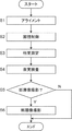
図5に、この実施形態に係る眼科装置の動作例のフロー図を示す。 FIG. 5 shows a flow chart of an operation example of the ophthalmic apparatus according to this embodiment.
(S1)
被検者の顔を顔受け部で固定した後、XYアライメント系2によるXYアライメントとZアライメント系1によるZアライメントとによりヘッド部が被検眼Eの検査位置に移動される。検査位置とは、被検眼Eの検査を行うことが可能な位置である。例えば、処理部9(制御部110)は、撮像素子59の撮像面上に結像された前眼部像の撮像信号を取得し、表示部170(表示部10の表示画面10a)に前眼部像E’を表示させる。その後、上記のXYアライメントとZアライメントとによりヘッド部が被検眼Eの検査位置に移動される。ヘッド部の移動は、制御部110による指示に従って、制御部110によって実行されるが、ユーザによる操作若しくは指示に従って制御部110によって実行されてもよい。
(S1)
After the face of the subject is fixed by the face receiving portion, the head portion is moved to the inspection position of the eye E to be inspected by the XY alignment by the
また、制御部110は、レフ測定光源61、合焦レンズ74及び合焦レンズ43を連動させて、光軸に沿って原点、例えば、0Dに相当する位置に移動させる。
Further, the
(S2)
制御部110は、液晶パネル41に固視標を表示させる。それにより、所望の固視位置に被検眼Eを注視させる。
(S2)
The
(S3)
次に、制御部110は、他覚測定を実行する。すなわち、制御部110は、レフ測定投影系6によりリング状光束を被検眼Eの眼底Efに投影させ、レフ測定受光系7を通じて撮像素子59により検出された戻り光に基づくリング像を眼屈折力算出部121に解析させる。眼屈折力算出部121は、上記のように球面度数S、乱視度数C及び乱視軸角度Aを求める。制御部110では、算出された球面度数Sなどが記憶部112に記憶される。
(S3)
Next, the
また、レフ測定前又はレフ測定後に、制御部110は、ケラト測定を実行することが可能である。この場合、制御部110は、ケラトリング光源32を点灯させ、撮像素子59により検出されたケラトリング像を眼屈折力算出部121に解析させる。眼屈折力算出部121は、上記のようにケラトリング像を解析することにより角膜曲率半径を算出し、算出された角膜曲率半径から角膜屈折力、角膜乱視度及び角膜乱視軸角度を算出する。制御部110では、算出された角膜屈折力などが記憶部112に記憶される。
Further, the
(S4)
次に、制御部110は、自覚検査を実行する。まず、制御部110は、S3において求められた球面度数S、乱視度数C及び乱視軸角度Aが矯正されるように合焦レンズ43及びVCCレンズ46を制御する。次に、制御部110は、例えば、操作部180に対するユーザの指示に基づき、液晶パネル41を制御することにより所望の視標を表示させる。被検者は、眼底Efに投影された視標に対する応答を行う。例えば、視力測定用の視標の場合には、被検者の応答により被検眼の視力値が決定される。視標の選択とそれに対する被検者の応答が、検者又は制御部110の判断により繰り返し行われる。検者又は制御部110は、被検者からの応答に基づいて視力値或いは処方値(S、C、A)を決定する。
(S4)
Next, the
(S5)
制御部110は、断層像撮影を行うか否かを判定する。例えば、操作部180に対するユーザの操作又は指示に基づいて、制御部110は、断層像撮影を行うか否かを判定する。このとき、S3において得られた他覚測定結果やS4において得られた自覚検査結果を表示部170に表示させ、ユーザに断層像撮影を行うか否かの判断を補助するための情報を提供することが可能である。断層像撮影を行うと判定されたとき(S5:Y)、眼科装置の動作はS6に移行する。断層像撮影を行わないと判定されたとき(S5:N)、眼科装置の動作は終了する(エンド)。
(S5)
The
また、制御部110が、S3において得られた他覚測定結果及びS4において得られた自覚検査結果の少なくとも1つに基づいて自動で断層像撮影を行うように眼科装置の制御を行うことが可能である。
Further, the
(S6)
S5において断層像撮影を行うと判定されたとき(S5:Y)、制御部110は、OCT光学系8により眼底Efの所定の部位を測定光でスキャンさせ、演算処理部120に被検眼Eの断層像を形成させる。以上で、眼科装置の動作は、終了となる(エンド)。
(S6)
When it is determined in S5 that the tomographic image is to be taken (S5: Y), the
例えば、S3における他覚測定においてリング状光束が投影された部位を測定光でスキャンし、得られた当該部位の断層像を表示部170に表示させる。それにより、検者等は、リング状光束が投影された測定部位の断層像を観察することができるため、S3において取得された他覚測定結果の信頼性を確認することが可能になり、S3における他覚測定結果の精度を向上させることができる。
For example, the portion where the ring-shaped luminous flux is projected in the objective measurement in S3 is scanned with the measurement light, and the obtained tomographic image of the portion is displayed on the
例えば、被検眼Eの黄斑の近傍を測定光でスキャンすることにより得られた黄斑の近傍の部位の断層像を表示部170に表示させる。この場合、検者等は、黄斑の近傍の部位の断層像を観察することができるため、S4において取得された自覚検査結果の信頼性を確認することが可能になり、S4における自覚検査結果の精度を向上させることができる。
For example, the
<<第1変形例>>
実施形態に係る眼科装置の光学系の構成は、図1及び図2において説明した構成に限定されるものではない。
<< First modification >>
The configuration of the optical system of the ophthalmic apparatus according to the embodiment is not limited to the configuration described in FIGS. 1 and 2.
図6及び図7に、実施形態の第1変形例に係る眼科装置の光学系の構成例を示す。図6において、図1と同様の部分には同一符号を付し、適宜説明を省略する。図7において、図6と同様の部分には同一符号を付し、適宜説明を省略する。以下では、第1変形例に係る眼科装置の光学系の構成について、実施形態に係る眼科装置の光学系の構成との相違点を中心に説明する。 6 and 7 show a configuration example of the optical system of the ophthalmic apparatus according to the first modification of the embodiment. In FIG. 6, the same parts as those in FIG. 1 are designated by the same reference numerals, and the description thereof will be omitted as appropriate. In FIG. 7, the same parts as those in FIG. 6 are designated by the same reference numerals, and the description thereof will be omitted as appropriate. Hereinafter, the configuration of the optical system of the ophthalmic apparatus according to the first modification will be described focusing on the differences from the configuration of the optical system of the ophthalmic apparatus according to the embodiment.
実施形態の第1変形例に係る眼科装置の光学系の構成が実施形態に係る眼科装置の光学系の構成と異なる点は、OCT光学系8における光スキャナー84の構成である。具体的には、ガルバノミラー84Yとガルバノミラー84Xとの間に反射ミラー85、リレーレンズ87A及び87Bが配置されている。リレーレンズ87Bの上流側の焦点位置にガルバノミラー84Xが配置されている。リレーレンズ87Aの下流側の焦点位置にガルバノミラー84Yが配置されている。反射ミラー85は、ガルバノミラー84Xにより偏向された測定光LSをガルバノミラー84Yに導くように配置されている。図7に示すように、ガルバノミラー84Y及びガルバノミラー84Xのそれぞれは、被検眼Eの瞳と光学的に共役な位置(瞳共役位置Q)に配置されている。
The configuration of the optical system of the ophthalmic apparatus according to the first modification of the embodiment is different from the configuration of the optical system of the ophthalmic apparatus according to the embodiment in the configuration of the
コリメートレンズ86により平行光束とされた測定光LSは、ガルバノミラー84Xにより眼底EfをX方向にスキャンするように偏向される。ガルバノミラー84Xにより偏向された測定光LSは、リレーレンズ87B及び87Aを通過し、反射ミラー85により偏向される。反射ミラー85により偏向された測定光LSは、ガルバノミラー84Yにより眼底EfをY方向にスキャンするように偏向される。
The measurement light LS converted into a parallel luminous flux by the collimating
実施形態の第1変形例に係る眼科装置の動作は実施形態に係る眼科装置の動作と同様であるため、説明を省略する。 Since the operation of the ophthalmic apparatus according to the first modification of the embodiment is the same as the operation of the ophthalmic apparatus according to the embodiment, the description thereof will be omitted.
第1変形例によれば、ガルバノミラー84X及び84Yの双方が瞳共役位置Qに配位置されるため、実施形態よりも高い横分解能で干渉光の検出が可能になる。また、ガルバノミラー84X及び84Yが光学的に共役な位置に配置されているため、合焦レンズ82を移動しても共役関係を維持しつつ、干渉信号の強度を高めてより高画質な断層像の取得が可能になる。
According to the first modification, since both the galvanometer mirrors 84X and 84Y are arranged at the pupil conjugate position Q, it is possible to detect the interference light with a higher lateral resolution than that of the embodiment. Further, since the galvanometer mirrors 84X and 84Y are arranged at optically conjugate positions, the intensity of the interference signal is increased while maintaining the conjugate relationship even when the focusing
<<第2変形例>>
実施形態又はその第1変形例に係る眼科装置の光学系ではガルバノミラー84X及び84Yにより測定光LSを偏向する場合について説明したが、実施形態に係る眼科装置の構成はこれに限定されるものではない。
<< Second modification >>
In the optical system of the ophthalmic apparatus according to the embodiment or the first modification thereof, the case where the measurement light LS is deflected by the galvanometer mirrors 84X and 84Y has been described, but the configuration of the ophthalmic apparatus according to the embodiment is not limited to this. Absent.
図8及び図9に、実施形態の第2変形例に係る眼科装置の光学系の構成例を示す。図8において、図1と同様の部分には同一符号を付し、適宜説明を省略する。図9において、図8と同様の部分には同一符号を付し、適宜説明を省略する。以下では、実施形態の第2変形例に係る眼科装置の光学系の構成について、実施形態に係る眼科装置の光学系の構成との相違点を中心に説明する。 8 and 9 show a configuration example of the optical system of the ophthalmic apparatus according to the second modification of the embodiment. In FIG. 8, the same parts as those in FIG. 1 are designated by the same reference numerals, and the description thereof will be omitted as appropriate. In FIG. 9, the same parts as those in FIG. 8 are designated by the same reference numerals, and the description thereof will be omitted as appropriate. Hereinafter, the configuration of the optical system of the ophthalmic apparatus according to the second modification of the embodiment will be described focusing on the difference from the configuration of the optical system of the ophthalmic apparatus according to the embodiment.
実施形態の第2変形例に係る眼科装置の光学系の構成が実施形態に係る眼科装置の光学系の構成と異なる点は、光スキャナー84に代えてイメージローテーター89が設けられている点である。イメージローテーター89は、OCT光学系8の光軸に配置され、当該光軸を中心に回転可能に設けられる。光ファイバーf2及びコリメートレンズ86の光軸は、イメージローテーター89の光軸と交差するように配置される。図9に示すように、光ファイバーf2のファイバー端面は、被検眼Eの眼底Efと光学的に共役な位置(眼底共役位置P)に配置されるように、合焦レンズ82が移動される。イメージローテーター89は、被検眼Eの瞳と光学的に共役な位置(瞳共役位置Q)に配置されている。
The configuration of the optical system of the ophthalmic apparatus according to the second modification of the embodiment is different from the configuration of the optical system of the ophthalmic apparatus according to the embodiment in that an
イメージローテーター89は、図示しない回転機構によりOCT光学系8の光軸を中心に回転される。この回転機構は、処理部9からの制御を受け、イメージローテーター89を回転させる。コリメートレンズ86により平行光束とされた測定光LSは、回転されるイメージローテーター89によりサークル状に偏向される。イメージローテーター89により偏向された測定光LSは、反射ミラー83により合焦レンズ82に向けて偏向される。
The
例えば、眼底Efに投影されるリング状光束と同じ大きさになるように光ファイバーf2等を傾けて配置することにより、眼底Efへのリング状光束の投影位置を測定光LSでスキャンすることができる。それにより、眼底Efへのリング状光束の投影位置における断層像を取得することができる。なお、イメージローテーター89の光軸に対する光ファイバーf2等の傾斜角度を変更する機構を設け、処理部9からの制御により光ファイバーf2等の傾斜角度を調整するようにしてもよい。
For example, by tilting the optical fiber f2 or the like so as to have the same magnitude as the ring-shaped luminous flux projected on the fundus Ef, the projection position of the ring-shaped luminous flux on the fundus Ef can be scanned by the measurement light LS. .. Thereby, a tomographic image at the projection position of the ring-shaped luminous flux on the fundus Ef can be acquired. A mechanism for changing the tilt angle of the optical fiber f2 or the like with respect to the optical axis of the
第2変形例に係る眼科装置の処理系では、上記のようにイメージローテーター89に対する回転制御が可能になっている。例えば、主制御部111が、回転機構を制御することによりイメージローテーター89を回転させる。
In the processing system of the ophthalmic apparatus according to the second modification, the rotation control for the
第2変形例によれば、簡素な構成で、被検眼Eの眼底Efを測定光LSでサークル状にスキャンすることが可能になる。それにより、他覚測定においてリング状光束が投影された測定部位の断層像を簡素な構成で取得できるため、他覚測定結果の信頼性を確認することが可能になり、他覚測定結果の精度を向上させることができる。 According to the second modification, the fundus Ef of the eye E to be inspected can be scanned in a circle with the measurement light LS with a simple configuration. As a result, it is possible to acquire a tomographic image of the measurement site on which the ring-shaped luminous flux is projected in objective measurement with a simple configuration, so it is possible to confirm the reliability of the objective measurement result and the accuracy of the objective measurement result. Can be improved.
<眼科検査システム>
実施形態又はその変形例に係る眼科装置は、両眼を検査可能な眼科検査システムに適用すること可能である。
<Ophthalmic examination system>
The ophthalmologic apparatus according to the embodiment or a modification thereof can be applied to an ophthalmologic examination system capable of examining both eyes.
図10に、実施形態又はその変形例に係る眼科装置が適用された眼科検査システムの構成例のブロック図である。 FIG. 10 is a block diagram of a configuration example of an ophthalmic examination system to which an ophthalmic apparatus according to an embodiment or a modified example thereof is applied.
眼科検査システムは、測定ヘッド300を含む。測定ヘッド300は、図示しない支持部材により支持された保持部350により上方から吊り下げられる。測定ヘッド300は、移動機構310と、左検査ユニット320Lと、右検査ユニット320Rとを含む。左検査ユニット320L及び右検査ユニット320Rのそれぞれには、図示しない検眼窓が形成されている。被検者の左眼(左被検眼)は、左検査ユニット320Lに設けられた検眼窓を通じて検査が行われる。被検者の右眼(右被検眼)は、右検査ユニット320Rに設けられた検眼窓を通じて検査が行われる。
The ophthalmologic examination system includes a measuring
左検査ユニット320L及び右検査ユニット320Rは、移動機構310により独立に又は連動して3次元的に移動される。左検査ユニット320L及び右検査ユニット320Rの少なくとも一方には、実施形態又はその変形例に係る眼科装置が設けられる。
The
移動機構310は、水平動機構311L、311Rと、回動機構312L、312Rと、上下動機構313L、313Rとを含む。
The moving
水平動機構311Lは、回動機構312L、上下動機構313L及び左検査ユニット320Lを水平方向(横方向(X方向)、前後方向(Z方向))に移動する。それにより、左被検眼の配置位置に応じて、検眼窓の水平方向の位置を調整することができる。水平動機構311Lは、例えば、駆動手段や駆動手段により発生された駆動力を伝達する駆動力伝達手段などを用いた公知の構成を備え、図示しない制御装置からの制御信号を受けて回動機構312L等を水平方向に移動する。水平動機構311Lは、操作者による操作を受け、回動機構312L等を水平方向に手動で移動することも可能である。
The
水平動機構311Rは、回動機構312R、上下動機構313R及び右検査ユニット320Rを水平方向に移動する。それにより、右被検眼の配置位置に応じて、検眼窓の水平方向の位置を調整することができる。水平動機構311Rは、水平動機構311Lと同様の構成を備え、図示しない制御装置からの制御信号を受けて回動機構312R等を水平方向に移動する。水平動機構311Rは、操作者による操作を受け、回動機構312R等を水平方向に手動で移動することも可能である。
The horizontal movement mechanism 311R moves the
回動機構312Lは、鉛直方向(略鉛直方向)に延びる左眼用の回動軸(左回動軸)を中心に上下動機構313L及び左検査ユニット320Lを回動する。この回動軸と水平面とのなす角は、変更可能である。回動機構312Lは、例えば、駆動手段や駆動手段により発生された駆動力を伝達する駆動力伝達手段などを用いた公知の構成を備え、図示しない制御装置からの制御信号を受けて当該回動軸を中心に左検査ユニット320L等を回動する。回動機構312Lは、操作者による操作を受け、当該回動軸を中心に左検査ユニット320L等を手動で回動することも可能である。
The
回動機構312Rは、鉛直方向に延びる右眼用の回動軸(右回動軸)を中心に上下動機構313R及び右検査ユニット320Rを回動する。この回動軸と水平面とのなす角は、変更可能である。右眼用の回動軸は、左眼用の回動軸から所定の距離だけ離間した位置に配置された軸である。左眼用の回動軸と右眼用の回動軸との間の距離は、調整可能である。回動機構312Rは、回動機構312Lと同様の構成を備え、図示しない制御装置からの制御信号を受けて当該回動軸を中心に右検査ユニット320R等を回動する。回動機構312Rは、操作者による操作を受け、当該回動軸を中心に右検査ユニット320R等を手動で回動することも可能である。
The
回動機構312L、312Rにより左検査ユニット320L及び右検査ユニット320Rを回動することにより、左検査ユニット320Lと右検査ユニット320Rとの向きを相対的に変更することが可能である。例えば、左検査ユニット320Lと右検査ユニット320Rとが、被検者の左右眼の眼球回旋点を中心にそれぞれ逆方向に回転される。それにより、被検眼を輻輳させることができる。
By rotating the
上下動機構313Lは、左検査ユニット320Lを上下方向(鉛直方向、Y方向)に移動する。それにより、被検眼の配置位置に応じて、検眼窓の高さ方向の位置を調整することができる。上下動機構313Lは、例えば、駆動手段や駆動手段により発生された駆動力を伝達する駆動力伝達手段などを用いた公知の構成を備え、図示しない制御装置からの制御信号を受けて左検査ユニット320Lを上下方向に移動する。上下動機構313Lは、操作者による操作を受け、左検査ユニット320Lを上下方向に手動で移動することも可能である。
The
上下動機構313Rは、右検査ユニット320Rを上下方向に移動する。それにより、被検眼の配置位置に応じて、検眼窓の高さ方向の位置を調整することができる。上下動機構313Rは、上下動機構313Lによる移動に連動して右検査ユニット320Rを移動してもよいし、上下動機構313Lによる移動とは独立に右検査ユニット320Rを移動してもよい。上下動機構313Rは、上下動機構313Lと同様の構成を備え、図示しない制御装置からの制御信号を受けて右検査ユニット320Rを上下方向に移動する。上下動機構313Rは、操作者による操作を受け、右検査ユニット320Rを上下方向に手動で移動することも可能である。
The
左検査ユニット320L及び右検査ユニット320Rは、個別に動作可能である。
The
このような眼科検査システムによれば、両眼について自覚検査や他覚測定を簡便に行うことができる。 According to such an ophthalmologic examination system, subjective examinations and objective measurements can be easily performed on both eyes.
(作用・効果)
実施形態に係る眼科装置及び眼科検査システムの作用及び効果について説明する。
(Action / effect)
The operation and effect of the ophthalmic apparatus and the ophthalmic examination system according to the embodiment will be described.
実施形態に係る眼科装置は、対物レンズ(対物レンズ51)と、自覚検査光学系(視標投影系4)と、干渉光学系(OCT光学系8)とを含む。自覚検査光学系は、被検眼の収差を補正可能な光学素子(VCCレンズ46)を含み、対物レンズ及び光学素子を介して被検眼(被検眼E)に視標を投影する。干渉光学系は、光源(OCT光源91)からの光(光L0)を参照光(参照光LR)と測定光(測定光LS)とに分割し、対物レンズ及び光学素子を介して被検眼に測定光を照射し、その戻り光と参照光との干渉光(干渉光LC)を生成し、生成された干渉光を検出する。 The ophthalmic apparatus according to the embodiment includes an objective lens (objective lens 51), a subjective examination optical system (objective projection system 4), and an interference optical system (OCT optical system 8). The subjective test optical system includes an optical element (VCC lens 46) capable of correcting aberrations of the eye to be inspected, and projects an optotype onto the eye to be inspected (eye to be inspected E) via an objective lens and an optical element. The interference optical system divides the light (light L0) from the light source (OCT light source 91) into a reference light (reference light LR) and a measurement light (measurement light LS), and provides the eye to be inspected via an objective lens and an optical element. The measurement light is irradiated, interference light (interference light LC) between the return light and the reference light is generated, and the generated interference light is detected.
このような構成によれば、自覚検査光学系と共通の対物レンズを介して被検眼に測定光を照射し、その戻り光を検出することができるので、簡素な構成で自覚検査と光コヒーレンストモグラフィを用いた撮影や計測とが可能になる。特に、被検眼の収差を補正可能な光学素子を介して測定光を被検眼に照射することができるので、別途に取得された被検眼の乱視状態を矯正するように光学素子を制御することが可能である。それにより、光学素子を通じて被検眼に照射された測定光は測定部位においてより一点に収束されやすくなり、最適な横分解能で、干渉光の検出結果に基づく干渉信号を十分な強度で取得できるようになる。 According to such a configuration, the measurement light can be irradiated to the eye to be inspected through the objective lens common to the subjective examination optical system, and the return light can be detected. Therefore, the subjective examination and the optical coherence tomography can be performed with a simple configuration. It enables photography and measurement using graphics. In particular, since the measurement light can be applied to the eye to be inspected through an optical element capable of correcting the aberration of the eye to be inspected, the optical element can be controlled so as to correct the astigmatic state of the eye to be inspected separately acquired. It is possible. As a result, the measurement light irradiated to the eye to be inspected through the optical element can be more easily converged to one point at the measurement site, and the interference signal based on the detection result of the interference light can be acquired with sufficient intensity with the optimum lateral resolution. Become.
また、実施形態に係る眼科装置では、干渉光学系は、光学素子よりも上流側の自覚検査光学系の光路に配置され、自覚検査光学系の光路に干渉光学系の光路を結合する第1光路結合部材(ダイクロイックミラー81)を含んでもよい。 Further, in the ophthalmic apparatus according to the embodiment, the interference optical system is arranged in the optical path of the awareness inspection optical system on the upstream side of the optical element, and the first optical path that couples the optical path of the interference optical system with the optical path of the awareness inspection optical system. A coupling member (dycroic mirror 81) may be included.
このような構成によれば、第1光路結合部材により干渉光学系の光路を自覚検査光学系の光路に結合するようにしたので、穴開きプリズムを用いる場合等と比べて光学系の構成を簡素化でき、光学系の設計の自由度を向上させることができる。また、他の光学系を追加しやすくなり、拡張性を備えた構成とすることができる。 According to such a configuration, since the optical path of the interference optical system is coupled to the optical path of the subjective inspection optical system by the first optical path coupling member, the configuration of the optical system is simplified as compared with the case where a perforated prism is used. It is possible to improve the degree of freedom in the design of the optical system. In addition, it becomes easy to add another optical system, and the configuration can be expanded.
また、実施形態に係る眼科装置では、自覚検査光学系は、光学素子と第1光路結合部材との間に配置されている瞳レンズ(瞳レンズ45)を含んでもよい。 Further, in the ophthalmic apparatus according to the embodiment, the subjective examination optical system may include a pupil lens (pupil lens 45) arranged between the optical element and the first optical path coupling member.
このような構成によれば、瞳レンズ45よりも上流側で干渉光学系の光路と自覚検査光学系の光路とを結合するようにしたので、眼底に共役な位置を近くすることが可能になり、干渉光学系や自覚検査光学系を小さくすることができる。
According to such a configuration, since the optical path of the interference optical system and the optical path of the subjective examination optical system are coupled on the upstream side of the
また、実施形態に係る眼科装置では、自覚検査光学系は、当該自覚検査光学系の焦点位置を変更する第1合焦レンズ(合焦レンズ43)を含み、第1光路結合部材は、瞳レンズと第1合焦レンズとの間に配置されていてもよい。 Further, in the ophthalmic apparatus according to the embodiment, the subjective examination optical system includes a first focusing lens (focusing lens 43) that changes the focal position of the subjective examination optical system, and the first optical path coupling member is a pupil lens. It may be arranged between the first focusing lens and the first focusing lens.
このような構成によれば、干渉光学系にかかわらず自覚検査光学系の焦点位置を変更することができる。 According to such a configuration, the focal position of the subjective inspection optical system can be changed regardless of the interference optical system.
また、実施形態に係る眼科装置では、干渉光学系は、第1光路結合部材と光源との間に配置され、当該干渉光学系の焦点位置を変更する第2合焦レンズ(合焦レンズ82)を含んでもよい。 Further, in the ophthalmic apparatus according to the embodiment, the interference optical system is arranged between the first optical path coupling member and the light source, and the second focusing lens (focusing lens 82) that changes the focal position of the interference optical system. May include.
このような構成によれば、自覚検査光学系にかかわらず干渉光学系の焦点位置を変更することができる。それにより、自覚検査光学系及び干渉光学系のそれぞれに最適な焦点位置に変更することができる。例えば、第1合焦レンズにより自覚検査光学系の焦点位置を変更しつつ、第2合焦レンズにより被検眼の前眼部や脈絡膜などの任意の部位に干渉光学系の焦点位置を合わせることができる。 According to such a configuration, the focal position of the interference optical system can be changed regardless of the subjective inspection optical system. Thereby, the focal position can be changed to the optimum position for each of the subjective inspection optical system and the interference optical system. For example, while changing the focal position of the subjective examination optical system with the first focusing lens, the focal position of the interfering optical system can be adjusted to an arbitrary part such as the anterior segment of the eye to be inspected or the choroid with the second focusing lens. it can.
また、実施形態に係る眼科装置は、他覚測定光学系と、眼屈折力算出部とを含んでもよい。他覚測定光学系は、対物レンズを介して被検眼の眼底(眼底Ef)にリング状の測定パターンを照射し、眼底からの戻り光を検出する。眼屈折力算出部は、他覚測定光学系により検出された戻り光に基づくパターン像を解析することにより被検眼の屈折力を求める。他覚測定光学系は、対物レンズと光学素子との間に配置され、自覚検査光学系の光路に他覚測定光学系の光路を結合する第2光路結合部材(ダイクロイックミラー69)を含む。 Further, the ophthalmic apparatus according to the embodiment may include an objective measurement optical system and an ocular refractive force calculation unit. The objective measurement optical system irradiates the fundus (fundus Ef) of the eye to be inspected with a ring-shaped measurement pattern via an objective lens, and detects the return light from the fundus. The eye refractive power calculation unit obtains the refractive power of the eye to be inspected by analyzing a pattern image based on the return light detected by the objective measurement optical system. The objective measurement optical system is arranged between the objective lens and the optical element, and includes a second optical path coupling member (dichroic mirror 69) that connects the optical path of the objective measurement optical system to the optical path of the subjective inspection optical system.
このような構成によれば、自覚検査光学系と共通の対物レンズを介して他覚測定を行うようにしたので、簡素な構成で自覚検査と光コヒーレンストモグラフィを用いた撮影や計測と他覚測定とが可能になる。 According to such a configuration, objective measurement is performed through an objective lens common to the subjective inspection optical system, so that the subjective inspection, imaging and measurement using optical coherence tomography and objective measurement are performed with a simple configuration. Measurement becomes possible.
また、実施形態に係る眼科装置では、干渉光学系は、当該干渉光学系の光軸に配置され、光軸を中心に回転可能に配置され測定光を偏向するイメージローテーター(イメージローテーター89)を含んでもよい。 Further, in the ophthalmic apparatus according to the embodiment, the interference optical system includes an image rotator (image rotator 89) which is arranged on the optical axis of the interference optical system and is rotatably arranged around the optical axis to deflect the measurement light. It may be.
このような構成によれば、簡素な構成および制御で測定光を偏向することができる。 According to such a configuration, the measurement light can be deflected with a simple configuration and control.
また、実施形態に係る眼科装置では、干渉光学系は、測定光を導光する光ファイバー(光ファイバーf2)と、光ファイバーの出射端から出射された測定光を平行光束にするコリメートレンズ(コリメートレンズ86)と、を含み、イメージローテーターは、コリメートレンズにより平行光束とされた測定光を偏向し、光ファイバー及びコリメートレンズは、その光軸がイメージローテーターの光軸と交差するように配置されていてもよい。 Further, in the ophthalmic apparatus according to the embodiment, the interfering optical system includes an optical fiber (optical fiber f2) that guides the measurement light and a collimating lens (collimating lens 86) that converts the measurement light emitted from the exit end of the optical fiber into a parallel light beam. The image rotator may deflect the measurement light as a parallel light beam by the collimating lens, and the optical fiber and the collimating lens may be arranged so that their optical axes intersect the optical axis of the image rotator.
このような構成によれば、リング状の測定パターンが投影された被検眼の部位に対して簡素な構成で測定光でサークル状にスキャンし、当該部位の断層像を取得することが可能になる。それにより、他覚測定結果の信頼性を向上させることができる。 According to such a configuration, it is possible to scan the site of the eye to be inspected on which the ring-shaped measurement pattern is projected in a circle shape with the measurement light with a simple configuration, and acquire a tomographic image of the site. .. Thereby, the reliability of the objective measurement result can be improved.
実施形態に係る眼科検査システムは、左被検眼を検査するための左検査ユニット(左検査ユニット320L)と、右被検眼を検査するための右検査ユニット(右検査ユニット320R)と、を含み、左検査ユニット及び右検査ユニットの少なくとも一方は、上記のいずれかに記載の眼科装置を含む。
The ophthalmologic examination system according to the embodiment includes a left examination unit (left
このような構成によれば、簡素な構成で、両眼について自覚検査と光コヒーレンストモグラフィを用いた撮影や計測とが可能な眼科検査システムを提供することができる。 According to such a configuration, it is possible to provide an ophthalmologic examination system capable of performing subjective examination and imaging and measurement using optical coherence tomography for both eyes with a simple configuration.
(その他の変形例)
以上に示された実施形態は、この発明を実施するための一例に過ぎない。この発明を実施しようとする者は、この発明の要旨の範囲内において任意の変形、省略、追加等を施すことが可能である。
(Other variants)
The embodiments shown above are merely examples for carrying out the present invention. A person who intends to carry out the present invention can make arbitrary modifications, omissions, additions, etc. within the scope of the gist of the present invention.
上記の実施形態又はその変形例では、視標投影系4においてダイクロイックミラー81がリレーレンズ44と合焦レンズ43との間に配置されていたが、ダイクロイックミラー81が合焦レンズ43とリレーレンズ42との間に配置されていてもよい。この場合、合焦レンズ43により視標投影系4及びOCT光学系8の焦点位置を変更した後、合焦レンズ82によりOCT光学系8の焦点位置を微調整することができる。
In the above embodiment or a modification thereof, the
上記の実施形態又はその変形例において、ガルバノミラー84Yに代えて、OCT光学系8の光軸を中心に回転可能なイメージローテーターが設けられていてもよい。
In the above embodiment or a modification thereof, an image rotator that can rotate about the optical axis of the OCT optical system 8 may be provided instead of the
上記の実施形態又はその変形例では、干渉光学系はOCT撮影を行うものとして説明したが、OCTにより計測を行うものであってもよい。例えば、干渉光学系は、OCTにより、眼軸長、角膜圧、前房深度、水晶体厚などを計測するものであってもよい。 In the above embodiment or a modification thereof, the interference optical system has been described as performing OCT imaging, but measurement may be performed by OCT. For example, the interference optical system may measure the axial length, corneal pressure, anterior chamber depth, lens thickness, and the like by OCT.
眼圧測定機能、眼底撮影機能、前眼部撮影機能、光干渉断層撮影(OCT)機能、超音波検査機能など、眼科分野において使用可能な任意の機能を有する装置に対して、上記の実施形態に係る発明を適用することが可能である。なお、眼圧測定機能は眼圧計等により実現され、眼底撮影機能は眼底カメラや走査型検眼鏡(SLO)等により実現され、前眼部撮影機能はスリットランプ等により実現され、OCT機能は光干渉断層計等により実現され、超音波検査機能は超音波診断装置等により実現される。また、このような機能のうち2つ以上を具備した装置(複合機)に対してこの発明を適用することも可能である。 The above-described embodiment for an apparatus having an arbitrary function that can be used in the ophthalmic field, such as an intraocular pressure measurement function, a fundus photography function, an anterior ocular segment imaging function, an optical coherence tomography (OCT) function, and an ultrasonic examination function. It is possible to apply the invention according to. The intraocular pressure measurement function is realized by a tonometer or the like, the fundus photography function is realized by a fundus camera or a scanning ophthalmoscope (SLO) or the like, the anterior ocular segment imaging function is realized by a slit lamp or the like, and the OCT function is optical. It is realized by an interference tomometer or the like, and the ultrasonic inspection function is realized by an ultrasonic diagnostic apparatus or the like. It is also possible to apply the present invention to a device (multifunction device) having two or more of such functions.
4 視標投影系
5 観察系
6 レフ測定投影系
7 レフ測定受光系
8 OCT光学系
46 VCCレンズ
51 対物レンズ
81 ダイクロイックミラー
4
Claims (6)
被検眼の収差を補正可能な光学素子を含み、前記対物レンズ及び前記光学素子を介して可視光を用いて前記被検眼に視標を投影する自覚検査光学系と、
光源からの赤外光を参照光と測定光とに分割し、前記対物レンズ及び前記光学素子を介して前記被検眼に前記測定光を照射し、その戻り光と前記参照光との干渉光を生成し、生成された前記干渉光を検出する干渉光学系と、
前記対物レンズを介して赤外光を用いて前記被検眼の眼底にリング状の測定パターンを照射し、前記眼底からの戻り光を検出する他覚測定光学系と、
前記他覚測定光学系により検出された前記戻り光に基づくパターン像を解析することにより前記被検眼の屈折力を求める眼屈折力算出部と、
を含み、
前記干渉光学系は、前記光学素子よりも上流側の前記自覚検査光学系の光路に配置され、前記自覚検査光学系の光路に前記干渉光学系の光路を結合する第1光路結合部材を含み、
前記他覚測定光学系は、前記対物レンズと前記光学素子との間に配置され、前記第1光路結合部材により結合された光路に前記他覚測定光学系の光路を結合する第2光路結合部材を含み、
前記自覚検査光学系は、前記光学素子と前記第1光路結合部材との間に配置されている瞳レンズを含む、眼科装置。 With the objective lens
A subjective test optical system that includes an optical element capable of correcting aberrations of the eye to be inspected and projects an optotype onto the eye to be inspected using visible light through the objective lens and the optical element.
The infrared light from the light source is divided into a reference light and a measurement light, the measurement light is irradiated to the eye to be inspected through the objective lens and the optical element, and the return light and the interference light between the reference light are emitted. An interfering optical system that is generated and detects the generated interfering light,
An objective measurement optical system that irradiates the fundus of the eye to be inspected with a ring-shaped measurement pattern using infrared light through the objective lens and detects return light from the fundus.
An optical power calculation unit that obtains the refractive power of the eye to be inspected by analyzing a pattern image based on the return light detected by the objective measurement optical system.
Including
The interference optical system includes a first optical path coupling member that is arranged in the optical path of the awareness inspection optical system on the upstream side of the optical element and that couples the optical path of the interference optical system to the optical path of the awareness inspection optical system.
The objective measurement optical system is arranged between the objective lens and the optical element, and is a second optical path coupling member that couples the optical path of the objective measurement optical system to the optical path coupled by the first optical path coupling member. only including,
The subjective examination optical system including a pupil lens disposed between the optical element and the first optical path coupling member, ophthalmic devices.
前記第1光路結合部材は、前記瞳レンズと前記第1合焦レンズとの間に配置されている
ことを特徴とする請求項1に記載の眼科装置。 The subjective inspection optical system includes a first focusing lens that changes the focal position of the subjective inspection optical system.
The ophthalmic apparatus according to claim 1 , wherein the first optical path coupling member is arranged between the pupil lens and the first focusing lens.
ことを特徴とする請求項2に記載の眼科装置。 The second aspect of claim 2 , wherein the interference optical system includes a second focusing lens which is arranged between the first optical path coupling member and the light source and changes the focal position of the interference optical system. Ophthalmic device.
ことを特徴とする請求項1〜請求項3のいずれか一項に記載の眼科装置。 Claims 1 to 3 include an image rotator that is arranged on the optical axis of the interference optical system, is rotatably arranged around the optical axis, and deflects the measurement light. The ophthalmic apparatus according to any one of the above.
被検眼の収差を補正可能な光学素子を含み、前記対物レンズ及び前記光学素子を介して可視光を用いて前記被検眼に視標を投影する自覚検査光学系と、
光源からの赤外光を参照光と測定光とに分割し、前記対物レンズ及び前記光学素子を介して前記被検眼に前記測定光を照射し、その戻り光と前記参照光との干渉光を生成し、生成された前記干渉光を検出する干渉光学系と、
前記対物レンズを介して赤外光を用いて前記被検眼の眼底にリング状の測定パターンを照射し、前記眼底からの戻り光を検出する他覚測定光学系と、
前記他覚測定光学系により検出された前記戻り光に基づくパターン像を解析することにより前記被検眼の屈折力を求める眼屈折力算出部と、
を含み、
前記干渉光学系は、
前記光学素子よりも上流側の前記自覚検査光学系の光路に配置され、前記自覚検査光学系の光路に前記干渉光学系の光路を結合する第1光路結合部材と、
当該干渉光学系の光軸に配置され、前記光軸を中心に回転可能に配置され前記測定光を偏向するイメージローテーターと、
前記測定光を導光する光ファイバーと、
前記光ファイバーの出射端から出射された前記測定光を平行光束にするコリメートレンズと、
を含み、
前記他覚測定光学系は、前記対物レンズと前記光学素子との間に配置され、前記第1光路結合部材により結合された光路に前記他覚測定光学系の光路を結合する第2光路結合部材を含み、
前記イメージローテーターは、前記コリメートレンズにより平行光束とされた前記測定光を偏向し、
前記光ファイバー及び前記コリメートレンズは、その光軸が前記イメージローテーターの光軸と交差するように配置されている、眼科装置。 With the objective lens
A subjective test optical system that includes an optical element capable of correcting aberrations of the eye to be inspected and projects an optotype onto the eye to be inspected using visible light through the objective lens and the optical element.
The infrared light from the light source is divided into a reference light and a measurement light, the measurement light is irradiated to the eye to be inspected through the objective lens and the optical element, and the return light and the interference light between the reference light are emitted. An interfering optical system that is generated and detects the generated interfering light,
An objective measurement optical system that irradiates the fundus of the eye to be inspected with a ring-shaped measurement pattern using infrared light through the objective lens and detects return light from the fundus.
An optical power calculation unit that obtains the refractive power of the eye to be inspected by analyzing a pattern image based on the return light detected by the objective measurement optical system.
Including
The interference optical system is
A first optical path coupling member arranged in the optical path of the subjective inspection optical system on the upstream side of the optical element and coupling the optical path of the interference optical system to the optical path of the subjective inspection optical system.
An image rotator arranged on the optical axis of the interference optical system, rotatably arranged around the optical axis, and deflecting the measurement light.
An optical fiber that guides the measurement light and
A collimating lens that converts the measurement light emitted from the emission end of the optical fiber into a parallel luminous flux, and
Including
The objective measurement optical system is arranged between the objective lens and the optical element, and is a second optical path coupling member that couples the optical path of the objective measurement optical system to the optical path coupled by the first optical path coupling member. Including
The image rotator deflects the measurement light, which is converted into a parallel luminous flux by the collimating lens.
The optical fiber and the collimating lens, the optical axis is arranged to intersect with the optical axis of the image rotator, ophthalmic devices.
右被検眼を検査するための右検査ユニットと、
を含み、
前記左検査ユニット及び前記右検査ユニットの少なくとも一方は、請求項1〜請求項5のいずれか一項に記載の眼科装置を含む
ことを特徴とする眼科検査システム。 A left inspection unit for inspecting the left eye and
The right inspection unit for inspecting the right eye,
Including
An ophthalmologic examination system comprising the ophthalmic apparatus according to any one of claims 1 to 5 , wherein at least one of the left examination unit and the right examination unit includes the ophthalmic apparatus according to any one of claims 1 to 5.
Priority Applications (1)
| Application Number | Priority Date | Filing Date | Title |
|---|---|---|---|
| JP2020005134A JP6833081B2 (en) | 2020-01-16 | 2020-01-16 | Ophthalmic equipment and ophthalmic examination system |
Applications Claiming Priority (1)
| Application Number | Priority Date | Filing Date | Title |
|---|---|---|---|
| JP2020005134A JP6833081B2 (en) | 2020-01-16 | 2020-01-16 | Ophthalmic equipment and ophthalmic examination system |
Related Parent Applications (1)
| Application Number | Title | Priority Date | Filing Date |
|---|---|---|---|
| JP2016019388A Division JP6685144B2 (en) | 2016-02-04 | 2016-02-04 | Ophthalmic equipment and ophthalmic examination system |
Publications (2)
| Publication Number | Publication Date |
|---|---|
| JP2020072966A JP2020072966A (en) | 2020-05-14 |
| JP6833081B2 true JP6833081B2 (en) | 2021-02-24 |
Family
ID=70609705
Family Applications (1)
| Application Number | Title | Priority Date | Filing Date |
|---|---|---|---|
| JP2020005134A Active JP6833081B2 (en) | 2020-01-16 | 2020-01-16 | Ophthalmic equipment and ophthalmic examination system |
Country Status (1)
| Country | Link |
|---|---|
| JP (1) | JP6833081B2 (en) |
Families Citing this family (2)
| Publication number | Priority date | Publication date | Assignee | Title |
|---|---|---|---|---|
| JP7527855B2 (en) | 2020-06-15 | 2024-08-05 | 株式会社トプコン | Ophthalmic device, method for controlling ophthalmic device, and program |
| CN115553713B (en) * | 2022-11-09 | 2023-04-11 | 北京犀燃科技有限公司 | OCT and ophthalmic surgery equipment integration system |
Family Cites Families (6)
| Publication number | Priority date | Publication date | Assignee | Title |
|---|---|---|---|---|
| US8016420B2 (en) * | 2007-05-17 | 2011-09-13 | Amo Development Llc. | System and method for illumination and fixation with ophthalmic diagnostic instruments |
| JP2010259492A (en) * | 2009-04-30 | 2010-11-18 | Topcon Corp | Fundus observation device |
| JP2013031634A (en) * | 2011-06-30 | 2013-02-14 | Canon Inc | Imaging apparatus |
| JP2015033472A (en) * | 2013-08-08 | 2015-02-19 | 株式会社トプコン | Ophthalmologic image-capturing apparatus |
| JP2015128482A (en) * | 2014-01-06 | 2015-07-16 | 株式会社トプコン | Ophthalmologic apparatus |
| JP2015205176A (en) * | 2014-04-08 | 2015-11-19 | 株式会社トプコン | Ophthalmic equipment |
-
2020
- 2020-01-16 JP JP2020005134A patent/JP6833081B2/en active Active
Also Published As
| Publication number | Publication date |
|---|---|
| JP2020072966A (en) | 2020-05-14 |
Similar Documents
| Publication | Publication Date | Title |
|---|---|---|
| US11253148B2 (en) | Ophthalmological device and ophthalmological inspection system | |
| JP6616704B2 (en) | Ophthalmic apparatus and ophthalmic examination system | |
| US10849499B2 (en) | Ophthalmologic apparatus and method of controlling the same | |
| JP7304780B2 (en) | ophthalmic equipment | |
| EP3607871B1 (en) | Ophthalmologic apparatus and method of controlling the same | |
| JP7394948B2 (en) | ophthalmology equipment | |
| JP2019154985A (en) | Ophthalmological device | |
| JP6833081B2 (en) | Ophthalmic equipment and ophthalmic examination system | |
| JP2023102006A (en) | Ophthalmologic apparatus | |
| JP2017136217A (en) | Ophthalmic apparatus and ophthalmic examination system | |
| JP2023126596A (en) | Ophthalmologic apparatus and control method thereof | |
| JP7281877B2 (en) | ophthalmic equipment | |
| JP2022060588A (en) | Ophthalmologic apparatus and control method of ophthalmologic apparatus | |
| JP7164328B2 (en) | Ophthalmic device and control method for ophthalmic device | |
| JP7133995B2 (en) | Ophthalmic device and its control method | |
| JP7030577B2 (en) | Ophthalmic equipment | |
| JP7103814B2 (en) | Ophthalmic equipment | |
| JP7244211B2 (en) | Ophthalmic device and control method for ophthalmic device | |
| JP7103813B2 (en) | Ophthalmic equipment | |
| JP7116572B2 (en) | Ophthalmic device and ophthalmic information processing program | |
| JP2023102032A (en) | Ophthalmologic apparatus |
Legal Events
| Date | Code | Title | Description |
|---|---|---|---|
| A621 | Written request for application examination |
Free format text: JAPANESE INTERMEDIATE CODE: A621 Effective date: 20200116 |
|
| A977 | Report on retrieval |
Free format text: JAPANESE INTERMEDIATE CODE: A971007 Effective date: 20201125 |
|
| A131 | Notification of reasons for refusal |
Free format text: JAPANESE INTERMEDIATE CODE: A131 Effective date: 20201215 |
|
| A521 | Request for written amendment filed |
Free format text: JAPANESE INTERMEDIATE CODE: A523 Effective date: 20210107 |
|
| TRDD | Decision of grant or rejection written | ||
| A01 | Written decision to grant a patent or to grant a registration (utility model) |
Free format text: JAPANESE INTERMEDIATE CODE: A01 Effective date: 20210126 |
|
| A61 | First payment of annual fees (during grant procedure) |
Free format text: JAPANESE INTERMEDIATE CODE: A61 Effective date: 20210202 |
|
| R150 | Certificate of patent or registration of utility model |
Ref document number: 6833081 Country of ref document: JP Free format text: JAPANESE INTERMEDIATE CODE: R150 |
|
| R250 | Receipt of annual fees |
Free format text: JAPANESE INTERMEDIATE CODE: R250 |
|
| R250 | Receipt of annual fees |
Free format text: JAPANESE INTERMEDIATE CODE: R250 |