JP6816696B2 - Negative electrode and non-aqueous electrolyte secondary battery equipped with it - Google Patents
Negative electrode and non-aqueous electrolyte secondary battery equipped with it Download PDFInfo
- Publication number
- JP6816696B2 JP6816696B2 JP2017199512A JP2017199512A JP6816696B2 JP 6816696 B2 JP6816696 B2 JP 6816696B2 JP 2017199512 A JP2017199512 A JP 2017199512A JP 2017199512 A JP2017199512 A JP 2017199512A JP 6816696 B2 JP6816696 B2 JP 6816696B2
- Authority
- JP
- Japan
- Prior art keywords
- negative electrode
- heat
- active material
- silicon oxide
- microcapsules
- Prior art date
- Legal status (The legal status is an assumption and is not a legal conclusion. Google has not performed a legal analysis and makes no representation as to the accuracy of the status listed.)
- Active
Links
Images


Classifications
-
- H—ELECTRICITY
- H01—ELECTRIC ELEMENTS
- H01M—PROCESSES OR MEANS, e.g. BATTERIES, FOR THE DIRECT CONVERSION OF CHEMICAL ENERGY INTO ELECTRICAL ENERGY
- H01M4/00—Electrodes
- H01M4/02—Electrodes composed of, or comprising, active material
- H01M4/36—Selection of substances as active materials, active masses, active liquids
- H01M4/48—Selection of substances as active materials, active masses, active liquids of inorganic oxides or hydroxides
- H01M4/483—Selection of substances as active materials, active masses, active liquids of inorganic oxides or hydroxides for non-aqueous cells
-
- H—ELECTRICITY
- H01—ELECTRIC ELEMENTS
- H01M—PROCESSES OR MEANS, e.g. BATTERIES, FOR THE DIRECT CONVERSION OF CHEMICAL ENERGY INTO ELECTRICAL ENERGY
- H01M4/00—Electrodes
- H01M4/02—Electrodes composed of, or comprising, active material
- H01M4/36—Selection of substances as active materials, active masses, active liquids
- H01M4/362—Composites
- H01M4/364—Composites as mixtures
-
- H—ELECTRICITY
- H01—ELECTRIC ELEMENTS
- H01M—PROCESSES OR MEANS, e.g. BATTERIES, FOR THE DIRECT CONVERSION OF CHEMICAL ENERGY INTO ELECTRICAL ENERGY
- H01M4/00—Electrodes
- H01M4/02—Electrodes composed of, or comprising, active material
- H01M4/36—Selection of substances as active materials, active masses, active liquids
- H01M4/362—Composites
- H01M4/366—Composites as layered products
-
- H—ELECTRICITY
- H01—ELECTRIC ELEMENTS
- H01M—PROCESSES OR MEANS, e.g. BATTERIES, FOR THE DIRECT CONVERSION OF CHEMICAL ENERGY INTO ELECTRICAL ENERGY
- H01M10/00—Secondary cells; Manufacture thereof
- H01M10/05—Accumulators with non-aqueous electrolyte
- H01M10/052—Li-accumulators
- H01M10/0525—Rocking-chair batteries, i.e. batteries with lithium insertion or intercalation in both electrodes; Lithium-ion batteries
-
- H—ELECTRICITY
- H01—ELECTRIC ELEMENTS
- H01M—PROCESSES OR MEANS, e.g. BATTERIES, FOR THE DIRECT CONVERSION OF CHEMICAL ENERGY INTO ELECTRICAL ENERGY
- H01M10/00—Secondary cells; Manufacture thereof
- H01M10/42—Methods or arrangements for servicing or maintenance of secondary cells or secondary half-cells
- H01M10/4235—Safety or regulating additives or arrangements in electrodes, separators or electrolyte
-
- H—ELECTRICITY
- H01—ELECTRIC ELEMENTS
- H01M—PROCESSES OR MEANS, e.g. BATTERIES, FOR THE DIRECT CONVERSION OF CHEMICAL ENERGY INTO ELECTRICAL ENERGY
- H01M4/00—Electrodes
- H01M4/02—Electrodes composed of, or comprising, active material
- H01M4/13—Electrodes for accumulators with non-aqueous electrolyte, e.g. for lithium-accumulators; Processes of manufacture thereof
- H01M4/131—Electrodes based on mixed oxides or hydroxides, or on mixtures of oxides or hydroxides, e.g. LiCoOx
-
- H—ELECTRICITY
- H01—ELECTRIC ELEMENTS
- H01M—PROCESSES OR MEANS, e.g. BATTERIES, FOR THE DIRECT CONVERSION OF CHEMICAL ENERGY INTO ELECTRICAL ENERGY
- H01M4/00—Electrodes
- H01M4/02—Electrodes composed of, or comprising, active material
- H01M4/13—Electrodes for accumulators with non-aqueous electrolyte, e.g. for lithium-accumulators; Processes of manufacture thereof
- H01M4/133—Electrodes based on carbonaceous material, e.g. graphite-intercalation compounds or CFx
-
- H—ELECTRICITY
- H01—ELECTRIC ELEMENTS
- H01M—PROCESSES OR MEANS, e.g. BATTERIES, FOR THE DIRECT CONVERSION OF CHEMICAL ENERGY INTO ELECTRICAL ENERGY
- H01M4/00—Electrodes
- H01M4/02—Electrodes composed of, or comprising, active material
- H01M4/13—Electrodes for accumulators with non-aqueous electrolyte, e.g. for lithium-accumulators; Processes of manufacture thereof
- H01M4/134—Electrodes based on metals, Si or alloys
-
- H—ELECTRICITY
- H01—ELECTRIC ELEMENTS
- H01M—PROCESSES OR MEANS, e.g. BATTERIES, FOR THE DIRECT CONVERSION OF CHEMICAL ENERGY INTO ELECTRICAL ENERGY
- H01M4/00—Electrodes
- H01M4/02—Electrodes composed of, or comprising, active material
- H01M4/36—Selection of substances as active materials, active masses, active liquids
- H01M4/48—Selection of substances as active materials, active masses, active liquids of inorganic oxides or hydroxides
- H01M4/485—Selection of substances as active materials, active masses, active liquids of inorganic oxides or hydroxides of mixed oxides or hydroxides for inserting or intercalating light metals, e.g. LiTi2O4 or LiTi2OxFy
-
- H—ELECTRICITY
- H01—ELECTRIC ELEMENTS
- H01M—PROCESSES OR MEANS, e.g. BATTERIES, FOR THE DIRECT CONVERSION OF CHEMICAL ENERGY INTO ELECTRICAL ENERGY
- H01M4/00—Electrodes
- H01M4/02—Electrodes composed of, or comprising, active material
- H01M4/62—Selection of inactive substances as ingredients for active masses, e.g. binders, fillers
- H01M4/621—Binders
-
- H—ELECTRICITY
- H01—ELECTRIC ELEMENTS
- H01M—PROCESSES OR MEANS, e.g. BATTERIES, FOR THE DIRECT CONVERSION OF CHEMICAL ENERGY INTO ELECTRICAL ENERGY
- H01M4/00—Electrodes
- H01M4/02—Electrodes composed of, or comprising, active material
- H01M4/62—Selection of inactive substances as ingredients for active masses, e.g. binders, fillers
- H01M4/628—Inhibitors, e.g. gassing inhibitors, corrosion inhibitors
-
- H—ELECTRICITY
- H01—ELECTRIC ELEMENTS
- H01M—PROCESSES OR MEANS, e.g. BATTERIES, FOR THE DIRECT CONVERSION OF CHEMICAL ENERGY INTO ELECTRICAL ENERGY
- H01M4/00—Electrodes
- H01M4/02—Electrodes composed of, or comprising, active material
- H01M4/64—Carriers or collectors
- H01M4/66—Selection of materials
- H01M4/661—Metal or alloys, e.g. alloy coatings
-
- H—ELECTRICITY
- H01—ELECTRIC ELEMENTS
- H01M—PROCESSES OR MEANS, e.g. BATTERIES, FOR THE DIRECT CONVERSION OF CHEMICAL ENERGY INTO ELECTRICAL ENERGY
- H01M4/00—Electrodes
- H01M4/02—Electrodes composed of, or comprising, active material
- H01M2004/026—Electrodes composed of, or comprising, active material characterised by the polarity
- H01M2004/027—Negative electrodes
-
- H—ELECTRICITY
- H01—ELECTRIC ELEMENTS
- H01M—PROCESSES OR MEANS, e.g. BATTERIES, FOR THE DIRECT CONVERSION OF CHEMICAL ENERGY INTO ELECTRICAL ENERGY
- H01M4/00—Electrodes
- H01M4/02—Electrodes composed of, or comprising, active material
- H01M2004/026—Electrodes composed of, or comprising, active material characterised by the polarity
- H01M2004/028—Positive electrodes
-
- H—ELECTRICITY
- H01—ELECTRIC ELEMENTS
- H01M—PROCESSES OR MEANS, e.g. BATTERIES, FOR THE DIRECT CONVERSION OF CHEMICAL ENERGY INTO ELECTRICAL ENERGY
- H01M50/00—Constructional details or processes of manufacture of the non-active parts of electrochemical cells other than fuel cells, e.g. hybrid cells
- H01M50/50—Current conducting connections for cells or batteries
- H01M50/543—Terminals
- H01M50/547—Terminals characterised by the disposition of the terminals on the cells
- H01M50/55—Terminals characterised by the disposition of the terminals on the cells on the same side of the cell
-
- H—ELECTRICITY
- H01—ELECTRIC ELEMENTS
- H01M—PROCESSES OR MEANS, e.g. BATTERIES, FOR THE DIRECT CONVERSION OF CHEMICAL ENERGY INTO ELECTRICAL ENERGY
- H01M50/00—Constructional details or processes of manufacture of the non-active parts of electrochemical cells other than fuel cells, e.g. hybrid cells
- H01M50/50—Current conducting connections for cells or batteries
- H01M50/543—Terminals
- H01M50/552—Terminals characterised by their shape
- H01M50/553—Terminals adapted for prismatic, pouch or rectangular cells
-
- Y—GENERAL TAGGING OF NEW TECHNOLOGICAL DEVELOPMENTS; GENERAL TAGGING OF CROSS-SECTIONAL TECHNOLOGIES SPANNING OVER SEVERAL SECTIONS OF THE IPC; TECHNICAL SUBJECTS COVERED BY FORMER USPC CROSS-REFERENCE ART COLLECTIONS [XRACs] AND DIGESTS
- Y02—TECHNOLOGIES OR APPLICATIONS FOR MITIGATION OR ADAPTATION AGAINST CLIMATE CHANGE
- Y02E—REDUCTION OF GREENHOUSE GAS [GHG] EMISSIONS, RELATED TO ENERGY GENERATION, TRANSMISSION OR DISTRIBUTION
- Y02E60/00—Enabling technologies; Technologies with a potential or indirect contribution to GHG emissions mitigation
- Y02E60/10—Energy storage using batteries
Landscapes
- Chemical & Material Sciences (AREA)
- Chemical Kinetics & Catalysis (AREA)
- Electrochemistry (AREA)
- General Chemical & Material Sciences (AREA)
- Engineering & Computer Science (AREA)
- Materials Engineering (AREA)
- Manufacturing & Machinery (AREA)
- Composite Materials (AREA)
- Inorganic Chemistry (AREA)
- Battery Electrode And Active Subsutance (AREA)
Description
本開示は、負極、およびそれを備える非水電解質二次電池に関する。 The present disclosure relates to a negative electrode and a non-aqueous electrolyte secondary battery including the negative electrode.
特開2016−046033号公報(特許文献1)には、負極活物質として酸化ケイ素などのシリコンを含む粒子を備えたリチウム二次電池用の負極活物質が開示されている。 Japanese Unexamined Patent Publication No. 2016-046033 (Patent Document 1) discloses a negative electrode active material for a lithium secondary battery including particles containing silicon such as silicon oxide as the negative electrode active material.
なお、特開平10−270084号公報(特許文献2)には、温度上昇によりカプセルが破れて内包物が放出される感熱性マイクロカプセルを電極合材の表面に塗布し、それにより電池内部の反応を阻害することが記載されています。 In Japanese Patent Application Laid-Open No. 10-270884 (Patent Document 2), heat-sensitive microcapsules in which capsules are torn and inclusions are released due to temperature rise are applied to the surface of the electrode mixture, thereby causing a reaction inside the battery. It is described that it inhibits.
酸化ケイ素は、黒鉛等の炭素系負極活物質よりも高容量であり、二次電池の高容量化の観点から、負極活物質の材料として注目されている。しかし、酸化ケイ素は、炭素系負極活物質よりも充放電時の膨張率および収縮率が大きい。 Silicon oxide has a higher capacity than carbon-based negative electrode active materials such as graphite, and is attracting attention as a material for negative electrode active materials from the viewpoint of increasing the capacity of secondary batteries. However, silicon oxide has a larger expansion rate and contraction rate during charging and discharging than the carbon-based negative electrode active material.
したがって、図3を参照して、釘5による釘さし等により、セパレータ30による絶縁が破壊されると、正極(正極集電体11および正極合材層12)と釘5と負極(負極集電体21および負極合材層22)との間で、図3に示される矢印方向の短絡電流が生じて、内部短絡が生じる。これにより、短絡部(釘5)の近傍が発熱する。
Therefore, referring to FIG. 3, when the insulation by the
ここで、図2(a)および(b)を参照して、負極活物質が酸化ケイ素3を含む場合、急速な放電により酸化ケイ素3が大きく収縮する。そのため、負極合材層に空隙が生じ、そこに電解液1が流れ込む(図2(a)に示される状態から図2(b)に示される状態となる)。ここで、内部短絡による発熱で電池内の温度は上昇しているため、電解液1が負極活物質(炭素系負極活物質2および酸化ケイ素3)と反応して、それにより更なる温度上昇(熱暴走)が生じる虞があった。
Here, referring to FIGS. 2A and 2B, when the negative electrode active material contains
したがって、本開示の課題は、負極合材層中に酸化ケイ素を含有する非水電解質二次電池用の負極、およびそれを備える非水電解質二次電池において、内部短絡等による発熱時に、電解液と負極活物質との反応による更なる温度上昇を抑制することである。 Therefore, an object of the present disclosure is that in a negative electrode for a non-aqueous electrolyte secondary battery containing silicon oxide in the negative electrode mixture layer and a non-aqueous electrolyte secondary battery including the negative electrode, an electrolytic solution is generated when heat is generated due to an internal short circuit or the like. This is to suppress a further temperature rise due to the reaction between the negative electrode and the negative electrode active material.
〔1〕 本開示の非水電解質二次電池用の負極は、負極集電体と、負極集電体の表面に形成された負極合材層と、を備える。
負極合材層は、酸化ケイ素を含む負極活物質と、熱膨張型マイクロカプセルと、を含有する。
負極活物質の総量に対する酸化ケイ素の割合は、30質量%以下である。
負極活物質の総量に対する熱膨張型マイクロカプセルの配合率は、0.5質量%以上である。
負極合材層に含まれる熱膨張型マイクロカプセルのうち、酸化ケイ素と接触している熱膨張型マイクロカプセルの割合は、70質量%以上である。
[1] The negative electrode for the non-aqueous electrolyte secondary battery of the present disclosure includes a negative electrode current collector and a negative electrode mixture layer formed on the surface of the negative electrode current collector.
The negative electrode mixture layer contains a negative electrode active material containing silicon oxide and a heat-expandable microcapsule.
The ratio of silicon oxide to the total amount of the negative electrode active material is 30% by mass or less.
The compounding ratio of the heat-expandable microcapsules with respect to the total amount of the negative electrode active material is 0.5% by mass or more.
Among the heat-expandable microcapsules contained in the negative electrode mixture layer, the proportion of the heat-expandable microcapsules in contact with silicon oxide is 70% by mass or more.
本開示によれば、負極合材層中に熱膨張型マイクロカプセルを含有することにより、負極合材層中に酸化ケイ素を含有する非水電解質二次電池用の負極、およびそれを備える非水電解質二次電池において、内部短絡等による発熱時に、電解液と負極活物質との反応による更なる温度上昇を抑制することができる。その理由は、以下のように考えられる。 According to the present disclosure, a negative electrode for a non-aqueous electrolyte secondary battery containing silicon oxide in the negative electrode mixture layer by containing a heat-expandable microcapsule in the negative electrode mixture layer, and a non-water solution including the same. In the electrolyte secondary battery, when heat is generated due to an internal short circuit or the like, it is possible to suppress a further temperature rise due to the reaction between the electrolytic solution and the negative electrode active material. The reason is considered as follows.
図1(a)および(b)に示されるように、内部短絡(釘差し)等による発熱時には、酸化ケイ素3が急速な放電により大きく収縮する。しかしながら、本開示においては、発熱によって熱膨張型マイクロカプセル4が膨張することで、酸化ケイ素3の収縮による空隙が埋められる。それにより、負極合材層への電解液1の流れ込みが抑制され、電解液1と負極活物質(炭素系負極活物質2および酸化ケイ素3)との接触が抑制される。このため、電解液と負極活物質との反応による更なる温度上昇(熱暴走)が抑制される。
As shown in FIGS. 1A and 1B, when heat is generated due to an internal short circuit (nail insertion) or the like, the
なお、本発明者らの検討により、下記(i)〜(iii)の条件を満たすことにより、内部短絡等による発熱時に、酸化ケイ素の収縮によって生じる空隙を熱膨張型マイクロカプセルによってより確実に埋めることができるため、電解液と負極活物質との反応による更なる温度上昇を確実に抑制することができることが見出された。
(i) 負極活物質の総量に対する酸化ケイ素の割合は、30質量%以下である。
(ii) 負極活物質の総量に対する熱膨張型マイクロカプセルの配合率は、0.5質量%以上である。
(iii) 負極合材層に含まれる熱膨張型マイクロカプセルのうち、酸化ケイ素と接触している熱膨張型マイクロカプセルの割合は、70質量%以上である。
According to the study by the present inventors, by satisfying the following conditions (i) to (iii), the voids generated by the shrinkage of silicon oxide are more reliably filled with the thermal expansion type microcapsules when heat is generated due to an internal short circuit or the like. Therefore, it has been found that further temperature rise due to the reaction between the electrolytic solution and the negative electrode active material can be reliably suppressed.
(I) The ratio of silicon oxide to the total amount of the negative electrode active material is 30% by mass or less.
(Ii) The compounding ratio of the heat-expandable microcapsules to the total amount of the negative electrode active material is 0.5% by mass or more.
(Iii) Among the heat-expandable microcapsules contained in the negative electrode mixture layer, the proportion of the heat-expandable microcapsules in contact with silicon oxide is 70% by mass or more.
〔2〕 熱膨張型マイクロカプセルは、熱可塑性樹脂からなるシェルと、該シェル内に収容された熱膨張剤と、を含むことが好ましい。この場合、内部短絡等による発熱時に、熱膨張剤の気化、昇華等により熱膨張型マイクロカプセルが瞬時に膨張するため、電解液と負極活物質との反応による更なる温度上昇をより確実に抑制することができる。 [2] The thermal expansion type microcapsules preferably include a shell made of a thermoplastic resin and a thermal expansion agent contained in the shell. In this case, when heat is generated due to an internal short circuit or the like, the thermal expansion type microcapsules expand instantly due to vaporization, sublimation, etc. of the thermal expansion agent, so that further temperature rise due to the reaction between the electrolytic solution and the negative electrode active material is more reliably suppressed. can do.
〔3〕 本開示は、上記〔1〕または〔2〕に記載の負極を備える、非水電解質二次電池にも関する。上記の負極を備えることにより、内部短絡等による発熱時に、電解液と負極活物質との反応による更なる温度上昇を抑制することができる。 [3] The present disclosure also relates to a non-aqueous electrolyte secondary battery provided with the negative electrode according to the above [1] or [2]. By providing the above-mentioned negative electrode, it is possible to suppress a further temperature rise due to the reaction between the electrolytic solution and the negative electrode active material when heat is generated due to an internal short circuit or the like.
以下、本開示の実施形態(以下「本実施形態」と記される)が説明される。ただし、以下の説明は、本開示の範囲を限定するものではない。 Hereinafter, embodiments of the present disclosure (hereinafter referred to as “the present embodiment”) will be described. However, the following description does not limit the scope of the present disclosure.
<非水電解質二次電池>
本明細書の「非水電解質二次電池」は、電解質に水を含まない電池を示す。以下、非水電解質二次電池が「電池」と略記される場合がある。
<Non-aqueous electrolyte secondary battery>
The term "non-aqueous electrolyte secondary battery" as used herein refers to a battery that does not contain water in the electrolyte. Hereinafter, the non-aqueous electrolyte secondary battery may be abbreviated as "battery".
図4は、本実施形態の非水電解質二次電池の構成の一例を示す概略図である。電池100は、電池ケース80を含む。電池ケース80は、角形(扁平直方体形)である。ただし、本実施形態の電池ケースは、円筒形であってもよい。電池ケース80は、Al合金、ステンレス(SUS)、鉄(Fe)等の金属材料、あるいは樹脂材料により構成され得る。電池ケース80は、金属材料と樹脂材料との複合材料(例えば、アルミラミネートフィルム製の袋等)によって構成されていてもよい。
FIG. 4 is a schematic view showing an example of the configuration of the non-aqueous electrolyte secondary battery of the present embodiment. The
電池ケース80は密閉されている。電池ケース80には、端子81が設けられている。電池ケース80は、図示しない電流遮断機構(CID)、ガス排出弁、注液孔等を備えていてもよい。電池ケース80は、電極群50および電解液を収納している。電極群50は、端子81と電気的に接続されている。
The
図5は、本実施形態の電極群の構成の一例を示す概略図である。電極群50は、巻回型である。すなわち電極群50は、正極10、セパレータ30、負極20およびセパレータ30がこの順序で積層され、さらにこれらが渦巻状に巻回されることにより構成されている。電極群50は、扁平状に成形されていてもよい。ただし、本実施形態の電極群は、積層型であってもよい。積層型の電極群は、正極と負極との間にセパレータが挟まれつつ、正極と負極とが交互に積層されることにより構成される。
FIG. 5 is a schematic view showing an example of the configuration of the electrode group of the present embodiment. The
《正極》
図6は、本実施形態の正極の構成の一例を示す概略図である。正極10は、帯状のシートである。正極10は、正極集電体11と、正極合材層12とを含む。正極合材層12は、正極集電体11の表面に担持されている。正極合材層12は、正極活物質を含む。正極10は、端子81との接続位置として、正極集電体11が正極合材層12から露出した部分を有していてもよい。
《Positive electrode》
FIG. 6 is a schematic view showing an example of the configuration of the positive electrode of the present embodiment. The
〔正極集電体〕
正極集電体11は、正極集電体11は、導電性を有する電極基材である。正極集電体11は、例えば5μm以上50μ以下の厚さを有してもよい。正極集電体11は、例えば、純Al箔、Al合金箔等であってもよい。
[Positive current collector]
The positive electrode
〔正極合材層〕
正極合材層12は、正極集電体11の表面(表裏両面または一方の表面)に形成されている。正極合材層12は、例えば、10〜200μmの厚さを有してもよいし、100〜200μmの厚さを有してもよい。正極合材層12は、例えば、80〜98質量%の正極活物質と、1〜15質量%の導電材と、その残部のバインダとを含み得る。
[Positive electrode mixture layer]
The positive
《負極》
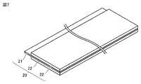
図7は、本実施形態の負極の構成の一例を示す概略図である。負極20は、帯状のシートである。負極20は、負極集電体21と、負極集電体21の表面に形成された負極合材層22と、を備える。負極合材層22は、例えば、負極集電体21の表面に担持されている。負極20は、端子81との接続位置として、負極集電体21が負極合材層22から露出した部分を有していてもよい。
《Negative electrode》
FIG. 7 is a schematic view showing an example of the configuration of the negative electrode of the present embodiment. The
〔負極集電体〕
負極集電体21は、例えば、5〜30μmの厚さを有してもよい。負極集電体21は、例えば、Cu箔であってもよい。Cu箔は、純Cu箔であってもよいし、Cu合金箔であってもよい。
[Negative electrode current collector]
The negative electrode
〔負極合材層〕
負極合材層22は、負極集電体21の表面(表裏両面または一方の表面)に形成されている。負極合材層22は、例えば、10〜200μmの厚さを有してもよいし、50〜150μmの厚さを有してもよい。
[Negative electrode mixture layer]
The negative
負極合材層22は、酸化ケイ素を含む負極活物質と、熱膨張性マイクロカプセルと、を含有する。また、負極合材層22は、さらに他の添加剤(バインダ、増粘材等)を含んでもよい。
The negative
(負極活物質)
本実施形態における負極活物質は、酸化ケイ素を含有する。酸化ケイ素は、一般式「SiOx」(ただし0.01≦x<2である)で表される化合物である。該一般式において、好ましくは0.1≦x≦1.5であり、より好ましくは0.5≦x≦1.5であり、さらに好ましくは0.5≦x≦1.0である。なお、このような酸化ケイ素が、以下、単に「SiO」と略記される場合がある。なお、SiOは、炭素系負極活物質よりも高容量であるため、負極合材層がSiOを含むことにより、二次電池の容量を向上させることが可能である。
(Negative electrode active material)
The negative electrode active material in the present embodiment contains silicon oxide. Silicon oxide is a compound represented by the general formula “SiO x ” (where 0.01 ≦ x <2). In the general formula, it is preferably 0.1 ≦ x ≦ 1.5, more preferably 0.5 ≦ x ≦ 1.5, and even more preferably 0.5 ≦ x ≦ 1.0. In addition, such silicon oxide may be simply abbreviated as "SiO" below. Since SiO has a higher capacity than the carbon-based negative electrode active material, it is possible to improve the capacity of the secondary battery by including SiO in the negative electrode mixture layer.
負極活物質は、酸化ケイ素以外の炭素系負極活物質などの他の活物質を含んでいてもよい。「炭素系負極活物質」とは、炭素を備え、Liイオンの吸蔵、放出が可能な物質を示す。炭素系負極活物質は、例えば、黒鉛、不定型炭素コート黒鉛、易黒鉛化性炭素(ソフトカーボン)および難黒鉛化性炭素(ハードカーボン)からなる群より選択される少なくとも1種であってもよい。負極合材層が炭素系負極活物質を含むことにより、容量、出力特性およびサイクル特性などのバランスが向上する可能性もある。 The negative electrode active material may contain other active materials such as a carbon-based negative electrode active material other than silicon oxide. The "carbon-based negative electrode active material" refers to a substance having carbon and capable of occluding and releasing Li ions. The carbon-based negative electrode active material may be at least one selected from the group consisting of, for example, graphite, atypical carbon-coated graphite, graphitizable carbon (soft carbon) and non-graphitizable carbon (hard carbon). Good. By including the carbon-based negative electrode active material in the negative electrode mixture layer, the balance of capacity, output characteristics, cycle characteristics, etc. may be improved.
本実施形態において、負極活物質の総量(酸化ケイ素および炭素系負極活物質の総量)に対する酸化ケイ素の割合は、30質量%以下である。30質量%を超える場合は、内部短絡等による発熱時に更なる温度上昇を十分に抑制することが難しくなる傾向がある。負極活物質の総量に対する酸化ケイ素の割合は、好ましくは1質量%以上30質量%以下であり、より好ましくは5質量%以上25質量%以下である。 In the present embodiment, the ratio of silicon oxide to the total amount of the negative electrode active material (total amount of silicon oxide and carbon-based negative electrode active material) is 30% by mass or less. If it exceeds 30% by mass, it tends to be difficult to sufficiently suppress a further temperature rise when heat is generated due to an internal short circuit or the like. The ratio of silicon oxide to the total amount of the negative electrode active material is preferably 1% by mass or more and 30% by mass or less, and more preferably 5% by mass or more and 25% by mass or less.
(熱膨張型マイクロカプセル)
本実施形態の熱膨張型マイクロカプセルは、加熱により膨張する性質を有する微小構造体である。
(Thermal expansion type microcapsules)
The heat-expandable microcapsules of the present embodiment are microstructures having the property of expanding by heating.
熱膨張型マイクロカプセルは、例えば、熱可塑性樹脂からなるシェル(外殻)と、該シェル内に封入された熱膨張剤と、を含む。このような熱膨張型マイクロカプセルにおいては、加熱により、シェル(熱可塑性樹脂)が軟化すると共に、シェル内部の熱膨張剤が気化または昇華して内圧が上昇することで、迅速に熱膨張型マイクロカプセルが膨張する。 The heat-expandable microcapsules include, for example, a shell (outer shell) made of a thermoplastic resin and a heat-expanding agent encapsulated in the shell. In such thermal expansion type microcapsules, the shell (thermoplastic resin) is softened by heating, and the thermal expansion agent inside the shell is vaporized or sublimated to increase the internal pressure, so that the thermal expansion type microcapsules are rapidly expanded. The capsule swells.
熱膨張型マイクロカプセルの膨張率は、例えば、体積比率で2〜100倍程度である。この場合、負極合材層中に含浸された状態で、酸化ケイ素(SiO)粒子の収縮分の容積を埋めるのに十分な程度まで膨張することが可能である。 The expansion coefficient of the heat-expandable microcapsules is, for example, about 2 to 100 times by volume. In this case, in the state of being impregnated in the negative electrode mixture layer, it is possible to expand to a degree sufficient to fill the contraction volume of the silicon oxide (SiO) particles.
したがって、熱膨張型マイクロカプセルを多数含有させておくことにより、温度上昇時に膨張した熱膨張型マイクロカプセルによって、負極合材層に侵入した電解液を押し出すことができる。このため、負極活物質の総量に対する熱膨張型マイクロカプセルの配合率は、0.5質量%以上であることが好ましい。一方で、熱膨張性マイクロカプセルの含有量が多くなると、電池の抵抗が上昇する傾向がある。このため、負極活物質の総量に対する熱膨張型マイクロカプセルの配合率は、25質量%以下であることが好ましく、20質量%以下であることがより好ましい。 Therefore, by containing a large number of thermal expansion type microcapsules, the electrolytic solution that has penetrated into the negative electrode mixture layer can be pushed out by the thermal expansion type microcapsules that expand when the temperature rises. Therefore, the compounding ratio of the heat-expandable microcapsules with respect to the total amount of the negative electrode active material is preferably 0.5% by mass or more. On the other hand, as the content of the heat-expandable microcapsules increases, the resistance of the battery tends to increase. Therefore, the compounding ratio of the heat-expandable microcapsules with respect to the total amount of the negative electrode active material is preferably 25% by mass or less, and more preferably 20% by mass or less.
シェル(熱可塑性樹脂)の軟化開始温度、および、内包物(熱膨張剤)の膨張(気化または昇華)開始温度は、電池の通常の動作温度(例えば、室温〜80℃程度)より高いことが好ましく、電池の内部短絡等による発熱時に熱暴走が開始される温度(例えば、80〜180℃)よりも低いことが好ましく、具体的には、例えば、100℃〜160℃程度である。これにより、電池が内部短絡等によって発熱したときにのみ、熱膨張性マイクロカプセルが膨張することになるため、電池の通常使用時において、熱膨張性マイクロカプセルの膨張による電池の破損等が防止される。なお、シェルが破裂しないように、熱膨張剤の膨張が開始される前にシェルが軟化していることが望ましいため、シェルの軟化開始温度は、熱膨張剤の膨張開始温度よりも低いことが好ましい。 The softening start temperature of the shell (thermoplastic resin) and the expansion (vaporization or sublimation) start temperature of the inclusion (thermal expansion agent) may be higher than the normal operating temperature of the battery (for example, about room temperature to 80 ° C.). It is preferably lower than the temperature at which thermal runaway starts (for example, 80 to 180 ° C.) when heat is generated due to an internal short circuit of the battery, and specifically, for example, about 100 ° C. to 160 ° C. As a result, the heat-expandable microcapsules expand only when the battery generates heat due to an internal short circuit or the like. Therefore, during normal use of the battery, damage to the battery due to expansion of the heat-expandable microcapsules is prevented. To. Since it is desirable that the shell is softened before the expansion of the thermal expansion agent is started so that the shell does not burst, the softening start temperature of the shell may be lower than the expansion start temperature of the thermal expansion agent. preferable.
シェルを構成する熱可塑性樹脂は、電解液に対する耐性に優れ、且つガスバリヤー性に優れることが好ましい。このような熱可塑性樹脂としては、例えば、塩化ビニリデンを含む(共)重合体、(メタ)アクリロニトリルを含む(共)重合体などが挙げられる。なお、熱膨張性マイクロカプセルの発泡特性、耐熱性等を改良するため、熱膨張性マイクロカプセルの調製時に、熱可塑性樹脂に架橋性単量体を配合してもよい。 It is preferable that the thermoplastic resin constituting the shell has excellent resistance to an electrolytic solution and excellent gas barrier property. Examples of such a thermoplastic resin include a (co) polymer containing vinylidene chloride, a (co) polymer containing (meth) acrylonitrile, and the like. In order to improve the foaming characteristics, heat resistance, etc. of the heat-expandable microcapsules, a crosslinkable monomer may be added to the thermoplastic resin when the heat-expandable microcapsules are prepared.
シェル中に封入される熱膨張剤としては、例えば、揮発性の炭化水素などの有機化合物が挙げられる。例えば、100℃以下の沸点を有する揮発性の炭化水素としては、プロパン、プロピレン、n−ブタン、イソブタン、ブテン、イソブテン、イソペンタン、ネオペンタン、n−ペンタン、n−ヘキサン、イソヘキサン、ヘプタン、石油エーテルなどが挙げられる。また、電池内部での安定性を考慮して、塩化メチル、メチレンクロライド、フロロトリクロロメタン、ジフロロジクロロメタン、クロロトリフロロメタン等のハロゲン化炭化水素やクロロフロロカーボン類等の不燃性または難燃性の化合物を熱膨張剤として用いてもよい。これらは、それぞれ単独で、あるいは2種以上を組合せて使用することができる。 Examples of the thermal expansion agent enclosed in the shell include organic compounds such as volatile hydrocarbons. For example, volatile hydrocarbons having a boiling point of 100 ° C. or lower include propane, propylene, n-butane, isobutane, butene, isobutene, isopentane, neopentane, n-pentane, n-hexane, isohexane, heptane, petroleum ether and the like. Can be mentioned. In addition, considering the stability inside the battery, halogenated hydrocarbons such as methyl chloride, methylene chloride, fluorotrichloromethane, difluorodichloromethane, and chlorotrifluoromethane, and nonflammable or flame-retardant compounds such as chlorofluorocarbons. The compound may be used as a thermal expansion agent. These can be used alone or in combination of two or more.
熱膨張型マイクロカプセルは、種々公知の方法によって製造することができ、例えば、水系分散媒体中で、少なくとも熱膨張剤と、シェルを構成する熱可塑性樹脂を得るための重合性単量体と、を含有する重合性混合物を懸濁重合する方法などにより製造することができる。具体的には、例えば、特公昭42−26524号公報、特開昭62−286534号公報、特開平4−292643号公報、特開平11−209504号公報等に開示される熱膨張型マイクロカプセルの製造方法を適用することができる。なお、マイクロカプセル化の懸濁重合においては、これら熱膨張剤は、シェルを構成する熱可塑性樹脂を与える重合性単量体(架橋性単量体を含む)100重量部に対し、例えばは、5〜100重量部程度の割合で使用すればよい。 The heat-expandable microcapsules can be produced by various known methods. For example, in an aqueous dispersion medium, at least a heat-expanding agent, a polymerizable monomer for obtaining a thermoplastic resin constituting a shell, and the like. It can be produced by a method such as suspension polymerization of a polymerizable mixture containing. Specifically, for example, the heat-expandable microcapsules disclosed in JP-A-42-26524, JP-A-62-286534, JP-A-4-292643, JP-A-11-209504, and the like. The manufacturing method can be applied. In the suspension polymerization of microencapsulation, these thermal expansion agents are used, for example, with respect to 100 parts by weight of the polymerizable monomer (including the crosslinkable monomer) that gives the thermoplastic resin constituting the shell. It may be used at a ratio of about 5 to 100 parts by weight.
熱膨張型マイクロカプセルの市販品としては、例えば、松本油脂製薬株式会社製のマツモトマイクロスフィアー(登録商標)FN−100SS(膨張開始温度:120℃)、マツモトマイクロスフィアーFN−80GS(膨張開始温度:100℃)、マツモトマイクロスフィアーF−48(膨張開始温度:90℃)、マツモトマイクロスフィアーF−65(膨張開始温度:110℃)などが挙げられる。 Commercially available products of heat-expandable microcapsules include, for example, Matsumoto Microspheres (registered trademark) FN-100SS (expansion start temperature: 120 ° C.) and Matsumoto Microspheres FN-80GS (expansion start) manufactured by Matsumoto Yushi Pharmaceutical Co., Ltd. Temperature: 100 ° C.), Matsumoto Microsphere F-48 (expansion start temperature: 90 ° C.), Matsumoto Microsphere F-65 (expansion start temperature: 110 ° C.), and the like.
熱膨張型マイクロカプセルの平均粒径は、好ましくは5〜30μmである。なお、本明細書において、「平均粒径」は、レーザ回折散乱法によって測定される体積基準の粒度分布において、微粒側から累積50%の粒径を意味する。また、熱膨張型マイクロカプセルは、粒径分布がシャープであることが好ましい。この場合、個々の熱膨張性マイクロカプセルの膨張開始温度のバラツキが少なく、所定の温度に達したときに迅速に全ての熱膨張性マイクロカプセルが膨張するため、SiOの収縮によって生じる空隙を迅速に埋めることが可能になると考えられる。 The average particle size of the heat-expandable microcapsules is preferably 5 to 30 μm. In the present specification, the "average particle size" means a cumulative 50% particle size from the fine particle side in the volume-based particle size distribution measured by the laser diffraction / scattering method. Further, the heat-expandable microcapsules preferably have a sharp particle size distribution. In this case, there is little variation in the expansion start temperature of the individual heat-expandable microcapsules, and all the heat-expandable microcapsules expand rapidly when a predetermined temperature is reached, so that the voids created by the shrinkage of SiO can be quickly created. It will be possible to fill it.
熱膨張性マイクロカプセルの平均粒径および粒径分布は、この分野で一般に使用されている方法により制御できる。例えば、熱膨張性マイクロカプセルを調製する際の懸濁重合において、分散安定剤の種類や量、乳化分散手段と乳化条件などを選択することによって制御できる。 The average particle size and particle size distribution of the heat-expandable microcapsules can be controlled by methods commonly used in the art. For example, in suspension polymerization when preparing heat-expandable microcapsules, it can be controlled by selecting the type and amount of dispersion stabilizer, emulsification / dispersion means and emulsification conditions.
熱膨張型マイクロカプセルは、従来公知の方法によって負極合材層中に含有させることができる。例えば、負極活物質、熱膨張型マイクロカプセル、バインダ、溶媒等を含む負極合材スラリーを負極集電体上に塗布し、乾燥することにより、負極合材層を形成することで、負極合材層中に熱膨張型マイクロカプセルを含有させることができる。 The heat-expandable microcapsules can be contained in the negative electrode mixture layer by a conventionally known method. For example, a negative electrode mixture slurry containing a negative electrode active material, thermal expansion type microcapsules, a binder, a solvent, etc. is applied onto a negative electrode current collector and dried to form a negative electrode mixture layer, thereby forming a negative electrode mixture. Thermal expansion type microcapsules can be contained in the layer.
負極合材層に含まれる熱膨張型マイクロカプセルのうち、酸化ケイ素と接触している熱膨張型マイクロカプセルの割合は、70質量%以上である。この場合、内部短絡等による発熱時に、熱膨張型マイクロカプセルが酸化ケイ素の近傍にあるため、酸化ケイ素の収縮による空隙を膨張した熱膨張型マイクロカプセルによって確実に埋めることができる。これにより、電解液と負極活物質との反応による更なる温度上昇をより確実に抑制することができる。なお、上記の酸化ケイ素と接触している熱膨張型マイクロカプセルの割合の上限は、特に限定されず、100質量%であってもよい。 Among the heat-expandable microcapsules contained in the negative electrode mixture layer, the proportion of the heat-expandable microcapsules in contact with silicon oxide is 70% by mass or more. In this case, since the thermal expansion type microcapsules are in the vicinity of the silicon oxide when heat is generated due to an internal short circuit or the like, the voids due to the shrinkage of the silicon oxide can be reliably filled with the expanded thermal expansion type microcapsules. This makes it possible to more reliably suppress a further temperature rise due to the reaction between the electrolytic solution and the negative electrode active material. The upper limit of the proportion of the heat-expandable microcapsules in contact with the silicon oxide is not particularly limited and may be 100% by mass.
酸化ケイ素と接触している熱膨張型マイクロカプセルの割合を高める方法としては、例えば、負極合材ペーストを負極集電体の表面に塗布し、乾燥することにより負極を製造する場合、予めSiO粒子と熱膨張型マイクロカプセルとを混合し、その混合物を負極合材層の他の成分および溶媒と混合することにより、負極合材ペーストを調製する方法が挙げられる。なお、例えば、電極合材層に用いられるSiO粒子および熱膨張性マイクロカプセルの全量に対して、予め混合するSiO粒子および熱膨張性マイクロカプセルの割合を変更することで、酸化ケイ素と接触している熱膨張型マイクロカプセルの割合を調整することができる。 As a method of increasing the proportion of heat-expandable microcapsules in contact with silicon oxide, for example, when a negative electrode mixture paste is applied to the surface of a negative electrode current collector and dried to produce a negative electrode, SiO particles are prepared in advance. And a heat-expandable microcapsule are mixed, and the mixture is mixed with other components and a solvent of the negative electrode mixture layer to prepare a negative electrode mixture paste. For example, by changing the ratio of the SiO particles and the heat-expandable microcapsules to be mixed in advance with respect to the total amount of the SiO particles and the heat-expandable microcapsules used in the electrode mixture layer, the cells come into contact with silicon oxide. The proportion of thermally inflatable microcapsules that are present can be adjusted.
(他の成分)
負極合材層は、上記以外の成分として、バインダ、増粘材、導電材等を含んでいてもよい。バインダとしては、例えば、スチレンブタジエンゴム(SBR)、アクリロニトリルブタジエンゴム(NBR)、ポリテトラフルオロエチレン(PTFE)等が挙げられる。増粘材としては、カルボキシメチルセルロース(CMC)、アルギン酸、ヒドロキシプロピルメチルセルロース(HPMC)、ポリエチレンオキシド(PEO)、ポリアクリル酸(PAA)、増粘多糖類などが挙げられる。
(Other ingredients)
The negative electrode mixture layer may contain a binder, a thickener, a conductive material and the like as components other than the above. Examples of the binder include styrene-butadiene rubber (SBR), acrylonitrile-butadiene rubber (NBR), polytetrafluoroethylene (PTFE) and the like. Examples of the thickening material include carboxymethyl cellulose (CMC), alginic acid, hydroxypropyl methyl cellulose (HPMC), polyethylene oxide (PEO), polyacrylic acid (PAA), and thickening polysaccharides.
《セパレータ》
セパレータ30は、帯状のシートである。セパレータ30は、正極10と負極20との間に介在している。セパレータ30は、電気絶縁性の多孔質膜である。セパレータ30は、例えば、10〜50μmの厚さを有してもよい。セパレータ30は、例えば、ポリエチレン(PE)製、ポリプロピレン(PP)製等であり得る。セパレータ30は、多層構造を有してもよい。セパレータ30は、例えば、PP製の多孔質膜、PE製の多孔質膜、およびPP製の多孔質膜がこの順序で積層されることにより、構成されていてもよい。
<< Separator >>
The
《電解液(非水電解質)》
電解液は、電極群50に含浸されている。電解液の一部は、電池ケース80の底部に貯留されている。なお、図4中の一点鎖線は、電解液の液面を示している。
<< Electrolyte (non-aqueous electrolyte) >>
The electrolytic solution is impregnated in the
電解液は、リチウム(Li)塩および溶媒を少なくとも含む。電解液は、たとえば0.5mоl/l以上2mоl/l以下のLi塩を含んでもよい。Li塩は支持電解質である。Li塩は溶媒に溶解している。Li塩は、たとえば、LiPF6、LiBF4、Li[N(FSO2)2]、Li[N(CF3SO2)2]等であってもよい。1種のLi塩が単独で使用されてもよい。2種以上のLi塩が組み合わされて使用されてもよい。 The electrolyte contains at least a lithium (Li) salt and a solvent. The electrolytic solution may contain, for example, a Li salt of 0.5 mL / l or more and 2 mL / l or less. Li salt is a supporting electrolyte. The Li salt is dissolved in the solvent. The Li salt may be, for example, LiPF 6 , LiBF 4 , Li [N (FSO 2 ) 2 ], Li [N (CF 3 SO 2 ) 2 ], or the like. One Li salt may be used alone. Two or more kinds of Li salts may be used in combination.
溶媒は非プロトン性である。すなわち本実施形態の電解液は非水電解質である。溶媒は、たとえば環状カーボネートおよび鎖状カーボネートの混合物であってもよい。混合比は、たとえば「環状カーボネート:鎖状カーボネート=1:9〜5:5(体積比)」であってもよい。 The solvent is aprotic. That is, the electrolytic solution of this embodiment is a non-aqueous electrolyte. The solvent may be, for example, a mixture of cyclic carbonate and chain carbonate. The mixing ratio may be, for example, "cyclic carbonate: chain carbonate = 1: 9 to 5: 5 (volume ratio)".
環状カーボネートは、たとえば、エチレンカーボネート(EC)、プロピレンカーボネート(PC)、ブチレンカーボネート(BC)、フルオロエチレンカーボネート(FEC)等であってもよい。1種の環状カーボネートが単独で使用されてもよい。2種以上の環状カーボネートが組み合わされて使用されてもよい。 The cyclic carbonate may be, for example, ethylene carbonate (EC), propylene carbonate (PC), butylene carbonate (BC), fluoroethylene carbonate (FEC), or the like. One type of cyclic carbonate may be used alone. Two or more cyclic carbonates may be used in combination.
鎖状カーボネートは、たとえば、ジメチルカーボネート(DMC)、エチルメチルカーボネート(EMC)、ジエチルカーボネート(DEC)等であってもよい。1種の鎖状カーボネートが単独で使用されてもよい。2種以上の鎖状カーボネートが組み合わされて使用されてもよい。 The chain carbonate may be, for example, dimethyl carbonate (DMC), ethyl methyl carbonate (EMC), diethyl carbonate (DEC) or the like. One type of chain carbonate may be used alone. Two or more chain carbonates may be used in combination.
溶媒は、たとえば、ラクトン、環状エーテル、鎖状エーテル、カルボン酸エステル等を含んでもよい。ラクトンは、たとえば、γ−ブチロラクトン(GBL)、δ−バレロラクトン等であってもよい。環状エーテルは、たとえば、テトラヒドロフラン(THF)、1,3−ジオキソラン、1,4−ジオキサン等であってもよい。鎖状エーテルは、1,2−ジメトキシエタン(DME)等であってもよい。カルボン酸エステルは、たとえば、メチルホルメート(MF)、メチルアセテート(MA)、メチルプロピオネート(MP)等であってもよい。 The solvent may include, for example, lactone, cyclic ether, chain ether, carboxylic acid ester and the like. The lactone may be, for example, γ-butyrolactone (GBL), δ-valerolactone and the like. The cyclic ether may be, for example, tetrahydrofuran (THF), 1,3-dioxolane, 1,4-dioxane or the like. The chain ether may be 1,2-dimethoxyethane (DME) or the like. The carboxylic acid ester may be, for example, methylformate (MF), methylacetate (MA), methylpropionate (MP) or the like.
<用途>
本実施形態の負極は、例えば、リチウムイオン二次電池(非水電解質二次電池)などの二次電池用の負極として用いることができる。その二次電池は、例えば、ハイブリッド自動車(HV)、電気自動車(EV)、プラグインハイブリッド車(PHV)等の電源として用いることができる。ただし、本開示の製造方法によって得られる負極は、このような用途に限られず、あらゆる二次電池に適用可能である。
<Use>
The negative electrode of the present embodiment can be used as a negative electrode for a secondary battery such as a lithium ion secondary battery (non-aqueous electrolyte secondary battery). The secondary battery can be used as a power source for, for example, a hybrid vehicle (HV), an electric vehicle (EV), a plug-in hybrid vehicle (PHV), or the like. However, the negative electrode obtained by the manufacturing method of the present disclosure is not limited to such applications, and can be applied to any secondary battery.
以下、実施例が説明される。ただし以下の例は、本開示の範囲を限定するものではない。以下、二次電池が「電池」と略記される場合がある。 Examples will be described below. However, the following examples do not limit the scope of the present disclosure. Hereinafter, the secondary battery may be abbreviated as "battery".
<比較例1〜4>
《負極の製造》
以下の材料が準備された。
負極活物質: 黒鉛(炭素系負極活物質) (平均粒径:20μm)
酸化ケイ素(平均粒径:20μm)
バインダ: SBR
増粘材: CMC
溶媒: 水
負極集電体: 銅箔(厚さ:10μm)
〔尚、比較例1〜4では、黒鉛と酸化ケイ素との総量(100%)に対する黒鉛および酸化ケイ素の各々の比率を表1の「活物質組成比率」欄に示すように変化させた。〕
<Comparative Examples 1 to 4>
<< Manufacturing of negative electrode >>
The following materials were prepared.
Negative electrode active material: Graphite (carbon-based negative electrode active material) (Average particle size: 20 μm)
Silicon oxide (average particle size: 20 μm)
Binder: SBR
Thickener: CMC
Solvent: Water Negative electrode current collector: Copper foil (thickness: 10 μm)
[In Comparative Examples 1 to 4, the ratios of graphite and silicon oxide to the total amount (100%) of graphite and silicon oxide were changed as shown in the “Active material composition ratio” column of Table 1. ]
10質量部の負極活物質(黒鉛および酸化ケイ素)、1質量部のバインダ、および、1質量部の増粘材が混合された。混合物に、さらに溶媒が加えられ、それらが混練されることにより、負極合材ペースト(スラリー)が調製された。なお、溶媒の添加量は、得られる負極合材ペーストの不揮発分率が50質量%となるように調整された。「不揮発分率」とは、溶媒を含む全ての原材料の質量合計に対する、溶媒以外の成分(不揮発成分)の質量比率を意味する。 10 parts by mass of negative electrode active material (graphite and silicon oxide), 1 part by mass of binder, and 1 part by mass of thickener were mixed. A solvent was further added to the mixture, and the solvents were kneaded to prepare a negative electrode mixture paste (slurry). The amount of the solvent added was adjusted so that the non-volatile fraction of the obtained negative electrode mixture paste was 50% by mass. The "nonvolatile fraction" means the mass ratio of components other than the solvent (nonvolatile components) to the total mass of all raw materials including the solvent.
調製された負極合材スラリーが、ダイコータを用いて、負極集電体の表面(表裏両面)に塗工され、乾燥された。これにより、負極集電体の両面に負極合材層が形成されてなる負極(負極シート)が得られた。該負極シートの厚みは80μmであり、負極合材層の幅は100mmであった。得られた負極(負極シート)は、所定の長さ(3300mm)に切断された。このようにして、比較例1〜4の負極が製造された。 The prepared negative electrode mixture slurry was applied to the surface (both front and back surfaces) of the negative electrode current collector using a die coater and dried. As a result, a negative electrode (negative electrode sheet) in which negative electrode mixture layers are formed on both sides of the negative electrode current collector was obtained. The thickness of the negative electrode sheet was 80 μm, and the width of the negative electrode mixture layer was 100 mm. The obtained negative electrode (negative electrode sheet) was cut to a predetermined length (3300 mm). In this way, the negative electrodes of Comparative Examples 1 to 4 were manufactured.
<比較例5、実施例1〜4>
比較例5および実施例1〜4では、負極合材中に、さらに熱膨張型マイクロカプセルが配合された。熱膨張型マイクロカプセルとしては、松本油脂製薬株式会社製のマツモトマイクロスフィアー(登録商標)FN−100SS(平均粒径:6〜11μm、熱膨張開始温度:120℃)が用いられ、そのシェルはアクリロニトリル系樹脂から構成され、シェル内に熱膨張剤である炭化水素が収容されていた。なお、予め熱膨張性マイクロカプセルの全量と酸化ケイ素とを粉体状態で混合しておき、その混合物を負極合材層の他の材料および溶媒と混合することで、負極合材ペーストを調製した。粉体状態での混合は、ハイスピードミキサーにて1000rpm、5分間行った。また、比較例5および実施例1〜4では、負極活物質の総量に対する熱膨張性マイクロカプセルの配合率を、表1に示されるように変化させた。以上の点以外は、比較例2と同様にして、比較例5および実施例1〜4の負極が製造された。
<Comparative Example 5, Examples 1 to 4>
In Comparative Example 5 and Examples 1 to 4, heat-expandable microcapsules were further blended in the negative electrode mixture. As the thermal expansion type microcapsule, Matsumoto Microspheres (registered trademark) FN-100SS (average particle size: 6 to 11 μm, thermal expansion start temperature: 120 ° C.) manufactured by Matsumoto Yushi Pharmaceutical Co., Ltd. is used, and the shell thereof is It was composed of an acrylonitrile resin, and a hydrocarbon, which is a thermal expansion agent, was contained in the shell. A negative electrode mixture paste was prepared by previously mixing the entire amount of the heat-expandable microcapsules and silicon oxide in a powder state, and mixing the mixture with other materials and a solvent of the negative electrode mixture layer. .. Mixing in the powder state was carried out at 1000 rpm for 5 minutes with a high speed mixer. Further, in Comparative Example 5 and Examples 1 to 4, the blending ratio of the heat-expandable microcapsules with respect to the total amount of the negative electrode active material was changed as shown in Table 1. Except for the above points, the negative electrodes of Comparative Example 5 and Examples 1 to 4 were manufactured in the same manner as in Comparative Example 2.
<実施例5、実施例6、比較例6>
黒鉛と酸化ケイ素との総量(100%)に対する黒鉛および酸化ケイ素の各々の比率を表1の「活物質組成比率」欄に示すように変化させた点以外は、実施例2と同様にして、実施例5、実施例6および比較例6の負極が製造された。
<Example 5, Example 6, Comparative Example 6>
In the same manner as in Example 2, except that the ratios of graphite and silicon oxide to the total amount (100%) of graphite and silicon oxide were changed as shown in the “active material composition ratio” column of Table 1. The negative electrodes of Example 5, Example 6 and Comparative Example 6 were manufactured.
<実施例7>
熱膨張性マイクロカプセルの半量についてのみ酸化ケイ素との粉体混合を行なった点以外は、実施例2と同様にして、実施例7の負極が製造された。
<Example 7>
The negative electrode of Example 7 was produced in the same manner as in Example 2 except that powder was mixed with silicon oxide only for half of the heat-expandable microcapsules.
<比較例7>
熱膨張性マイクロカプセルと酸化ケイ素との粉体混合を行なわなかった点以外は、実施例2と同様にして、比較例7の負極が製造された。
<Comparative Example 7>
The negative electrode of Comparative Example 7 was produced in the same manner as in Example 2 except that the heat-expandable microcapsules and silicon oxide were not powder-mixed.
<比較例9,10>
熱膨張型マイクロカプセルに代えて、放出型(内包物放出型)マイクロカプセルを用いた点以外は、比較例5および実施例1と同様にして、比較例9および10の電池を製造した。放出型マイクロカプセルとしては、特開平10−270084号公報(特許文献2)の[0029]に記載のマイクロカプセルと同じものを作製し使用した。なお、この放出型マイクロカプセルは、具体的には、シェルであるヘキサメチレンジイソシアネートと、該シェルの内包物(重合ポリマー)であるトリメチロールプロパントリアクリレートと、からなるマイクロカプセルである。
<Comparative Examples 9 and 10>
Batteries of Comparative Examples 9 and 10 were produced in the same manner as in Comparative Examples 5 and 1 except that the release type (inclusion release type) microcapsules were used instead of the heat expansion type microcapsules. As the release type microcapsules, the same microcapsules as those described in [0029] of JP-A-10-27084 (Patent Document 2) were prepared and used. Specifically, the release type microcapsules are microcapsules composed of hexamethylene diisocyanate, which is a shell, and trimethylolpropane triacrylate, which is an inclusion (polymerized polymer) of the shell.
<SiOと接触しているマイクロカプセルの割合の測定>
上記実施例および比較例の各負極の負極合材層について、SiOと接触しているマイクロカプセルの割合(マイクロカプセルの全量に対する割合)を、電極の断面SEM観察を行い、その視野範囲内のSiOと接触しているマイクロカプセルの個数と、視野全体のマイクロカプセルの個数を観察することによって測定した。測定結果を表1に示す。
<Measurement of the ratio of microcapsules in contact with SiO>
For the negative electrode mixture layer of each of the negative electrodes of the above Examples and Comparative Examples, the ratio of microcapsules in contact with SiO (ratio to the total amount of microcapsules) was observed by SEM observation of the cross section of the electrode, and the SiO in the viewing range was observed. It was measured by observing the number of microcapsules in contact with and the number of microcapsules in the entire field of view. The measurement results are shown in Table 1.
<二次電池の製造>
上記実施例および比較例の負極を用いて、非水電解質二次電池(リチウムイオン二次電池)が製造された。
<Manufacturing of secondary batteries>
A non-aqueous electrolyte secondary battery (lithium ion secondary battery) was manufactured using the negative electrodes of the above Examples and Comparative Examples.
《正極の製造》
以下の材料が準備された。
正極活物質: リチウムニッケルコバルトマンガン複合酸化物(LiNi1/3Co1/3Mn1/3O2)
導電材: アセチレンブラック(AB)
バインダ: ポリフッ化ビニリデン(PVDF)
溶媒: N−メチル−2−ピロリドン(NMP)
正極集電体: アルミニウム箔(厚さ:20μm)
<< Manufacturing of positive electrode >>
The following materials were prepared.
Positive electrode active material: Lithium nickel cobalt manganese composite oxide (LiNi 1/3 Co 1/3 Mn 1/3 O 2 )
Conductive material: Acetylene black (AB)
Binder: Polyvinylidene fluoride (PVDF)
Solvent: N-methyl-2-pyrrolidone (NMP)
Positive electrode current collector: Aluminum foil (thickness: 20 μm)
100質量部の正極活物質、10質量部の導電材、および、3質量部のバインダが、溶媒中で混合された。これにより正極合材ペーストが調製された。ダイコータにより、正極合材ペーストが正極集電体の表面(両面)に塗工され、乾燥されることにより、正極合材層(厚み:50μm、幅:94mm、未塗工幅:20mm)が形成された。これにより正極が製造された。正極は、さらにロールプレス機によって圧縮され、帯状に裁断された。得られた正極の厚みは70μmであり、長さは3000mmであった。また、正極合材層の幅は94mmであり、正極合材の非塗工部の幅は20mmであった。 100 parts by mass of the positive electrode active material, 10 parts by mass of the conductive material, and 3 parts by mass of the binder were mixed in the solvent. As a result, a positive electrode mixture paste was prepared. A positive electrode mixture paste is applied to the surface (both sides) of the positive electrode current collector by a die coater and dried to form a positive electrode mixture layer (thickness: 50 μm, width: 94 mm, uncoated width: 20 mm). Was done. As a result, a positive electrode was manufactured. The positive electrode was further compressed by a roll press and cut into strips. The thickness of the obtained positive electrode was 70 μm, and the length was 3000 mm. The width of the positive electrode mixture layer was 94 mm, and the width of the uncoated portion of the positive electrode mixture was 20 mm.
《セパレータ》
帯状のセパレータ(多孔質膜)が準備された。このセパレータは20μmの厚さを有する。このセパレータは、3層構造を有する。3層構造は、ポリプロピレンの多孔質層、ポリエチレンの多孔質層およびポリプロピレンの多孔質層がこの順序で積層されることにより構成されている。このセパレータの片面に耐熱層を形成したものが、電極群の製造に用いられた。
<< Separator >>
A strip-shaped separator (porous membrane) was prepared. This separator has a thickness of 20 μm. This separator has a three-layer structure. The three-layer structure is composed of a polypropylene porous layer, a polyethylene porous layer, and a polypropylene porous layer laminated in this order. A heat-resistant layer formed on one side of this separator was used for manufacturing an electrode group.
《電極群の製造》
正極、セパレータ、負極およびセパレータが、正極と負極との間にセパレータが介在するように積層され、さらに扁平状に巻回されることにより、巻回型の電極群が作製された。アルミニウム製の角型の外装ケースが準備された。電極群の芯材端部に端子を接合し、電極群が外装ケース内に収納された。
<< Manufacturing of electrode group >>
The positive electrode, the separator, the negative electrode, and the separator were laminated so that the separator was interposed between the positive electrode and the negative electrode, and further wound in a flat shape to produce a wound electrode group. A square outer case made of aluminum was prepared. A terminal was joined to the end of the core material of the electrode group, and the electrode group was housed in the outer case.
エチレンカーボネート(EC)、ジメチルカーボネート(DMC)およびエチルメチルカーボネート(EMC)が混合されることにより電解液溶媒が調製された。電解液溶媒にLiPF6が分散、溶解されることにより、以下の組成を備える電解液が調製された。
電解液溶媒: [EC:DMC:EMC=1:1:1(体積比)]
LiPF6: 1.0mоl/L
An electrolytic solution solvent was prepared by mixing ethylene carbonate (EC), dimethyl carbonate (DMC) and ethyl methyl carbonate (EMC). By dispersing and dissolving LiPF 6 in the electrolytic solution solvent, an electrolytic solution having the following composition was prepared.
Electrolyte solvent: [EC: DMC: EMC = 1: 1: 1 (volume ratio)]
LiPF 6 : 1.0 mol / L
所定量の電解液が外装ケース内に注入された。外装ケースが密閉された。以上より、非水電解質二次電池が製造された。この電池の理論容量は、4Ahであった。 A predetermined amount of electrolyte was injected into the outer case. The outer case was sealed. From the above, a non-aqueous electrolyte secondary battery was manufactured. The theoretical capacity of this battery was 4 Ah.
<電池性能評価>
〔常温抵抗の測定〕
上記実施例および比較例の各電池を3.7Vまで充電した後、25℃環境下で、40A(10C)の電流レートで10秒間放電し、このときの電圧降下量と電流レートとの関係から電池の抵抗(常温抵抗)を求めた。なお「C」は電流レートの単位である。「1C」は、1時間の充電により、充電率(SOC)が0%から100%に到達する電流レートを示す。測定結果を表1に示す。
<Battery performance evaluation>
[Measurement of room temperature resistance]
After charging each of the batteries of the above Examples and Comparative Examples to 3.7 V, the batteries are discharged at a current rate of 40 A (10 C) for 10 seconds in an environment of 25 ° C. The battery resistance (normal temperature resistance) was determined. Note that "C" is a unit of current rate. “1C” indicates a current rate at which the charge rate (SOC) reaches 0% to 100% after charging for 1 hour. The measurement results are shown in Table 1.
〔釘差し試験〕
釘差し試験が行われた。具体的には、電池が、4A(1C)の電流レートにより4.1Vまで充電された。その後、電池に直径3.0mmの釘が1.0mm/秒の速度で差し込まれた。
[Nail insertion test]
A nailing test was conducted. Specifically, the battery was charged to 4.1V at a current rate of 4A (1C). After that, a nail having a diameter of 3.0 mm was inserted into the battery at a speed of 1.0 mm / sec.
釘差し試験20秒後(釘差し試験の終了時から20秒経過後)の電池の側面中央部の温度が、その部分に設けられた熱電対によって測定された。測定結果を表1に示す。 Twenty seconds after the nailing test (20 seconds after the end of the nailing test), the temperature at the center of the side surface of the battery was measured by a thermocouple provided in that part. The measurement results are shown in Table 1.
さらに、釘差し試験2分後(釘差し試験の終了時から2分経過後)の電池の状態(発煙の有無)を目視で観察した。観察結果を表1に示す。 Further, the state of the battery (presence or absence of smoke) 2 minutes after the nailing test (2 minutes after the end of the nailing test) was visually observed. The observation results are shown in Table 1.

<結果>
表1に示される結果について、まず、比較例1〜4の結果から、負極活物質としてSiOが含まれる場合、釘刺し試験後(内部短絡等による発熱時)の温度が高く、発煙に至り易いと考えられる。なお、この傾向は、SiOの比率が増えるほど顕著であることが分かる。これは、釘刺し時に内部短絡による放電でSiOが大幅に収縮し、それによってできた負極合材層の空隙に電解液が流れ込み、電解液が負極活物質と反応して、更なる温度上昇(熱暴走)が起きたためであると考えられる。
<Result>
Regarding the results shown in Table 1, first, from the results of Comparative Examples 1 to 4, when SiO is contained as the negative electrode active material, the temperature after the nail piercing test (when heat is generated due to an internal short circuit, etc.) is high, and smoke is likely to occur. it is conceivable that. It can be seen that this tendency becomes more remarkable as the ratio of SiO increases. This is because the SiO shrinks significantly due to the discharge caused by an internal short circuit during nailing, and the electrolytic solution flows into the voids in the negative electrode mixture layer created by this, and the electrolytic solution reacts with the negative electrode active material, causing a further temperature rise ( It is probable that this was due to a thermal runaway.
比較例5および実施例1〜4の結果から、熱膨張性マイクロカプセルの配合量が0.5質量%未満である場合、釘差し試験後に発煙に至り、熱暴走の抑制効果が得られないことが分かる。これは、負極合材内の空隙を十分に埋めることができず、電解液を十分に押し出せないため、電解液と負極の発熱反応が起こったためであると考えられる。したがって、熱膨張性マイクロカプセルの配合量が0.5質量%以上である場合、内部短絡等による発熱時の温度上昇を十分に抑制することができると考えられる。 From the results of Comparative Example 5 and Examples 1 to 4, when the blending amount of the heat-expandable microcapsules is less than 0.5% by mass, smoke is generated after the nailing test, and the effect of suppressing thermal runaway cannot be obtained. I understand. It is considered that this is because the voids in the negative electrode mixture could not be sufficiently filled and the electrolytic solution could not be sufficiently extruded, so that an exothermic reaction between the electrolytic solution and the negative electrode occurred. Therefore, when the blending amount of the heat-expandable microcapsules is 0.5% by mass or more, it is considered that the temperature rise at the time of heat generation due to an internal short circuit or the like can be sufficiently suppressed.
また、熱膨張性マイクロカプセルの配合量が多くなると、電池抵抗(常温抵抗)が増加することが分かる。これは、熱膨張性マイクロカプセルが絶縁性であるためであると考えられる。電池抵抗の増加を抑制する観点からは、負極活物質の総量に対する熱膨張性マイクロカプセルの配合率は、好ましくは25質量%以下であり、より好ましくは20質量%以下である。 It can also be seen that the battery resistance (normal temperature resistance) increases as the amount of the heat-expandable microcapsules blended increases. It is considered that this is because the heat-expandable microcapsules are insulating. From the viewpoint of suppressing an increase in battery resistance, the compounding ratio of the heat-expandable microcapsules with respect to the total amount of the negative electrode active material is preferably 25% by mass or less, and more preferably 20% by mass or less.
実施例5および6の結果から、負極活物質中のSiOの比率を変化させても、釘刺し試験後の温度の低減効果が得られることが分かる。なお、比較例6(SiO:100質量%)では、釘刺し試験後の温度を十分に低減できず、発煙が生じた。このことから、負極活物質(炭素系負極活物質および酸化ケイ素)の総量に対するSiOの配合割合が多すぎると、釘刺し試験後(内部短絡等による発熱時)の温度上昇を十分に抑制することが難しくなり、発煙が生じやすくなる傾向があると考えられる。そして、負極活物質の総量に対するSiOの割合が30質量%以下である場合には、内部短絡等による発熱時の温度上昇を十分に抑制することができると考えられる。 From the results of Examples 5 and 6, it can be seen that the effect of reducing the temperature after the nail piercing test can be obtained even if the ratio of SiO in the negative electrode active material is changed. In Comparative Example 6 (SiO: 100% by mass), the temperature after the nail piercing test could not be sufficiently reduced, and smoke was generated. From this, if the compounding ratio of SiO to the total amount of the negative electrode active material (carbon-based negative electrode active material and silicon oxide) is too large, the temperature rise after the nail piercing test (when heat is generated due to an internal short circuit, etc.) is sufficiently suppressed. It is thought that this becomes difficult and smoke tends to occur easily. When the ratio of SiO to the total amount of the negative electrode active material is 30% by mass or less, it is considered that the temperature rise at the time of heat generation due to an internal short circuit or the like can be sufficiently suppressed.
実施例2、7および比較例7の結果から、熱膨張型マイクロカプセル(全量または半量)をSiOと予め粉体混合した場合、すなわち、負極合材層に含まれる熱膨張型マイクロカプセルのうち、酸化ケイ素(SiO)と接触している熱膨張型マイクロカプセルの割合が、70質量%以上である場合に、電解液と負極活物質との反応による更なる温度上昇を確実に抑制することができることが分かる。これは、内部短絡等による発熱時に、熱膨張型マイクロカプセルが酸化ケイ素の近傍にあれば、酸化ケイ素の収縮によって生じる空隙を熱膨張型マイクロカプセルによって確実に埋めることができるためであると考えられる。 From the results of Examples 2 and 7 and Comparative Example 7, the thermal expansion type microcapsules (total amount or half amount) were powder-mixed with SiO in advance, that is, among the thermal expansion type microcapsules contained in the negative electrode mixture layer. When the proportion of the heat-expandable microcapsules in contact with silicon oxide (SiO) is 70% by mass or more, it is possible to reliably suppress a further temperature rise due to the reaction between the electrolytic solution and the negative electrode active material. I understand. It is considered that this is because if the heat-expandable microcapsules are in the vicinity of the silicon oxide during heat generation due to an internal short circuit or the like, the voids generated by the shrinkage of the silicon oxide can be reliably filled by the heat-expandable microcapsules. ..
比較例8、9の結果から、特許文献2に開示される放出型マイクロカプセルを負極合材層中に配合した従来の電池においては、膨張性マイクロカプセルを配合した実施例よりも温度上昇の抑制効果は小さいことが分かる。これは、SiOの収縮によって生じる負極合材層の空隙への電解液の流れ込み量や速度が、放出型マイクロカプセルの内包物の放出による電池内部の反応阻害の量や速度より、大きくなっているためであると考えられる。尚、比較例8と9とを比較すると、マイクロカプセルとSiOを予め混合しても釘差し試験後の温度上昇の抑制効果は向上しないことが分かる。
From the results of Comparative Examples 8 and 9, in the conventional battery in which the release type microcapsules disclosed in
今回開示された実施形態および実施例はすべての点で例示であって、制限的なものではないと考えられるべきである。本開示の範囲は、上記の説明ではなくて、特許請求の範囲によって示され、特許請求の範囲と均等の意味および範囲内でのすべての変更が含まれることが意図される。 The embodiments and examples disclosed this time should be considered as exemplary in all respects and not restrictive. The scope of the present disclosure is shown by the scope of claims, not the above description, and is intended to include all modifications within the meaning and scope equivalent to the scope of claims.
1 電解液、2 黒鉛、3 酸化ケイ素(SiO)、4 熱膨張型マイクロカプセル、5 釘、10 正極、11 正極集電体、12 正極合材層、20 負極、21 負極集電体、22 負極合材層、30 セパレータ、50 電極群、80 電池ケース、81 端子、100 電池(非水電解質二次電池)。 1 Electrolyte, 2 Graphite, 3 Silicon oxide (SiO), 4 Thermal expansion type microcapsule, 5 Nail, 10 Positive electrode, 11 Positive electrode current collector, 12 Positive electrode mixture layer, 20 Negative electrode, 21 Negative electrode current collector, 22 Negative electrode Mixture layer, 30 separators, 50 electrode group, 80 battery case, 81 terminals, 100 batteries (non-aqueous electrolyte secondary battery).
Claims (3)
前記負極合材層は、酸化ケイ素を含む負極活物質と、熱膨張型マイクロカプセルと、を含有し、
前記負極活物質の総量に対する前記酸化ケイ素の割合は、30質量%以下であり、
前記負極活物質の総量に対する前記熱膨張型マイクロカプセルの配合率は、0.5質量%以上である、
前記負極合材層に含まれる前記熱膨張型マイクロカプセルのうち、前記酸化ケイ素と接触している前記熱膨張型マイクロカプセルの割合は、70質量%以上である、負極。 A negative electrode for a non-aqueous electrolyte secondary battery, comprising a negative electrode current collector and a negative electrode mixture layer formed on the surface of the negative electrode current collector.
The negative electrode mixture layer contains a negative electrode active material containing silicon oxide and a heat-expandable microcapsule.
The ratio of the silicon oxide to the total amount of the negative electrode active material is 30% by mass or less.
The compounding ratio of the heat-expandable microcapsules to the total amount of the negative electrode active material is 0.5% by mass or more.
The negative electrode having a ratio of the thermal expansion type microcapsules in contact with the silicon oxide of 70% by mass or more among the thermal expansion type microcapsules contained in the negative electrode mixture layer.
Priority Applications (3)
| Application Number | Priority Date | Filing Date | Title |
|---|---|---|---|
| JP2017199512A JP6816696B2 (en) | 2017-10-13 | 2017-10-13 | Negative electrode and non-aqueous electrolyte secondary battery equipped with it |
| US16/101,652 US10763498B2 (en) | 2017-10-13 | 2018-08-13 | Negative electrode and non-aqueous electrolyte secondary battery including the same |
| CN201811188710.6A CN109671909B (en) | 2017-10-13 | 2018-10-12 | Negative electrode and nonaqueous electrolyte secondary battery provided with same |
Applications Claiming Priority (1)
| Application Number | Priority Date | Filing Date | Title |
|---|---|---|---|
| JP2017199512A JP6816696B2 (en) | 2017-10-13 | 2017-10-13 | Negative electrode and non-aqueous electrolyte secondary battery equipped with it |
Publications (2)
| Publication Number | Publication Date |
|---|---|
| JP2019075239A JP2019075239A (en) | 2019-05-16 |
| JP6816696B2 true JP6816696B2 (en) | 2021-01-20 |
Family
ID=66096102
Family Applications (1)
| Application Number | Title | Priority Date | Filing Date |
|---|---|---|---|
| JP2017199512A Active JP6816696B2 (en) | 2017-10-13 | 2017-10-13 | Negative electrode and non-aqueous electrolyte secondary battery equipped with it |
Country Status (3)
| Country | Link |
|---|---|
| US (1) | US10763498B2 (en) |
| JP (1) | JP6816696B2 (en) |
| CN (1) | CN109671909B (en) |
Families Citing this family (5)
| Publication number | Priority date | Publication date | Assignee | Title |
|---|---|---|---|---|
| KR102016711B1 (en) * | 2017-12-21 | 2019-09-02 | 주식회사 엘지화학 | Secondary battery |
| WO2023008266A1 (en) * | 2021-07-27 | 2023-02-02 | 日本ゼオン株式会社 | Binder composition for electrochemical elements, slurry composition for electrochemical element electrodes, electrode for electrochemical elements, and electrochemical element |
| CN116344733B (en) * | 2021-12-15 | 2026-01-27 | 宁德时代新能源科技股份有限公司 | Positive electrode plate, secondary battery, battery module, battery pack and power utilization device |
| US20230268483A1 (en) * | 2022-02-18 | 2023-08-24 | Regents Of The University Of Minnesota | Organic sublimable material-assisted electrodes |
| CN116014077B (en) * | 2023-03-27 | 2023-07-07 | 江苏正力新能电池技术有限公司 | A lithium-ion battery negative pole piece and a lithium-ion battery |
Family Cites Families (14)
| Publication number | Priority date | Publication date | Assignee | Title |
|---|---|---|---|---|
| JPH10270084A (en) | 1997-03-27 | 1998-10-09 | Seiko Instr Inc | Nonaqueous electrolyte secondary battery |
| JP3609612B2 (en) * | 1998-04-28 | 2005-01-12 | 三洋電機株式会社 | Negative electrode for lithium secondary battery and lithium secondary battery using the same |
| JP2010108945A (en) * | 1998-05-13 | 2010-05-13 | Ube Ind Ltd | Non-aqueous secondary battery |
| JP4727021B2 (en) * | 2000-05-22 | 2011-07-20 | 株式会社クレハ | Electrode and non-aqueous battery using the same |
| KR100635737B1 (en) * | 2005-03-24 | 2006-10-17 | 삼성에스디아이 주식회사 | Lithium secondary battery |
| JP2007273127A (en) * | 2006-03-30 | 2007-10-18 | Matsushita Electric Ind Co Ltd | Non-aqueous secondary battery |
| BR112012012049B1 (en) * | 2009-11-20 | 2021-11-23 | Nissan Motor Co., Ltd | CURRENT COLLECTOR FOR BIPOLAR SECONDARY BATTERY, ELECTRODE FOR BIPOLAR SECONDARY BATTERY AND BIPOLAR SECONDARY BATTERY |
| US8999561B2 (en) * | 2010-05-12 | 2015-04-07 | Uchicago Argonne, Llc | Materials for electrochemical device safety |
| CN103688395A (en) * | 2011-07-29 | 2014-03-26 | 三洋电机株式会社 | Active substance for nonaqueous electrolyte secondary cell, method for producing same, and negative electrode using active substance |
| KR20150015503A (en) * | 2012-05-15 | 2015-02-10 | 가부시키가이샤 유에이씨제이 | Collector, electrode structure, nonaqueous electrolyte battery and power storage component, and method for producing collector |
| TW201539845A (en) * | 2013-09-30 | 2015-10-16 | Toppan Printing Co Ltd | Electrode for lithium ion secondary batteries, and lithium ion secondary battery |
| KR102258220B1 (en) * | 2013-12-26 | 2021-06-01 | 마쓰모토유시세이야쿠 가부시키가이샤 | Method for producing thermally expandable microspheres and use of same |
| JP2016046033A (en) | 2014-08-21 | 2016-04-04 | トヨタ自動車株式会社 | Negative electrode active material for lithium secondary battery |
| CN104466186B (en) * | 2014-11-17 | 2017-02-22 | 深圳市振华新材料股份有限公司 | Microcapsules and cathode materials for batteries and their preparation and application |
-
2017
- 2017-10-13 JP JP2017199512A patent/JP6816696B2/en active Active
-
2018
- 2018-08-13 US US16/101,652 patent/US10763498B2/en active Active
- 2018-10-12 CN CN201811188710.6A patent/CN109671909B/en active Active
Also Published As
| Publication number | Publication date |
|---|---|
| US20190115592A1 (en) | 2019-04-18 |
| CN109671909A (en) | 2019-04-23 |
| US10763498B2 (en) | 2020-09-01 |
| CN109671909B (en) | 2022-07-26 |
| JP2019075239A (en) | 2019-05-16 |
Similar Documents
| Publication | Publication Date | Title |
|---|---|---|
| JP6538689B2 (en) | Electrical insulation layer and battery device | |
| JP6816696B2 (en) | Negative electrode and non-aqueous electrolyte secondary battery equipped with it | |
| JP6960526B2 (en) | Positive electrode and lithium ion secondary battery with undercoat layer containing microcapsules | |
| JP6884269B2 (en) | Negative electrode including microcapsules and lithium ion secondary battery equipped with this | |
| JP4541324B2 (en) | Nonaqueous electrolyte secondary battery | |
| JP6499427B2 (en) | Lithium ion secondary battery | |
| JP5668993B2 (en) | Sealed nonaqueous electrolyte secondary battery and method for manufacturing the same | |
| JP6911700B2 (en) | Electrode group | |
| JP5664932B2 (en) | Secondary battery | |
| JP6881171B2 (en) | Negative electrode and lithium ion secondary battery | |
| WO2013080946A1 (en) | Separator for non-aqueous electrolyte cell and non-aqueous electrolyte cell using same | |
| JP2003031208A (en) | Non-aqueous electrolyte secondary battery | |
| JP6897507B2 (en) | Non-aqueous electrolyte secondary battery and its manufacturing method | |
| CN111326703B (en) | Nonaqueous electrolyte secondary battery | |
| JP5893811B1 (en) | Nonaqueous secondary battery separator, method for producing the same, and nonaqueous secondary battery | |
| JP6167943B2 (en) | Nonaqueous electrolyte secondary battery | |
| JP2020057500A (en) | Negative electrode, battery, and method for manufacturing negative electrode | |
| JPWO2016121350A1 (en) | Positive electrode for non-aqueous electrolyte secondary battery and non-aqueous electrolyte secondary battery | |
| JP6834870B2 (en) | Non-aqueous electrolyte secondary battery and its manufacturing method | |
| JP2016062832A (en) | Method for manufacturing secondary battery | |
| JP6801561B2 (en) | Non-aqueous electrolyte secondary battery | |
| JP2024064853A (en) | Composition for secondary battery negative electrode, negative electrode mixture layer, negative electrode for secondary battery, and lithium ion secondary battery | |
| JP2015043304A (en) | Nonaqueous electrolyte secondary battery | |
| JP2023167484A (en) | Composition, collector with under coat layer, electrode, and lithium ion secondary battery | |
| JP2017016945A (en) | Lithium ion secondary battery |
Legal Events
| Date | Code | Title | Description |
|---|---|---|---|
| A621 | Written request for application examination |
Free format text: JAPANESE INTERMEDIATE CODE: A621 Effective date: 20200219 |
|
| TRDD | Decision of grant or rejection written | ||
| A977 | Report on retrieval |
Free format text: JAPANESE INTERMEDIATE CODE: A971007 Effective date: 20201118 |
|
| A01 | Written decision to grant a patent or to grant a registration (utility model) |
Free format text: JAPANESE INTERMEDIATE CODE: A01 Effective date: 20201124 |
|
| A61 | First payment of annual fees (during grant procedure) |
Free format text: JAPANESE INTERMEDIATE CODE: A61 Effective date: 20201207 |
|
| R151 | Written notification of patent or utility model registration |
Ref document number: 6816696 Country of ref document: JP Free format text: JAPANESE INTERMEDIATE CODE: R151 |
|
| R250 | Receipt of annual fees |
Free format text: JAPANESE INTERMEDIATE CODE: R250 |
|
| R250 | Receipt of annual fees |
Free format text: JAPANESE INTERMEDIATE CODE: R250 |
|
| R250 | Receipt of annual fees |
Free format text: JAPANESE INTERMEDIATE CODE: R250 |