JP6815957B2 - door mirror - Google Patents
door mirror Download PDFInfo
- Publication number
- JP6815957B2 JP6815957B2 JP2017175908A JP2017175908A JP6815957B2 JP 6815957 B2 JP6815957 B2 JP 6815957B2 JP 2017175908 A JP2017175908 A JP 2017175908A JP 2017175908 A JP2017175908 A JP 2017175908A JP 6815957 B2 JP6815957 B2 JP 6815957B2
- Authority
- JP
- Japan
- Prior art keywords
- camera
- vehicle body
- door mirror
- cut filter
- vehicle
- Prior art date
- Legal status (The legal status is an assumption and is not a legal conclusion. Google has not performed a legal analysis and makes no representation as to the accuracy of the status listed.)
- Active
Links
- 238000003384 imaging method Methods 0.000 claims description 18
- 230000001012 protector Effects 0.000 claims description 17
- 238000001514 detection method Methods 0.000 description 9
- VYPSYNLAJGMNEJ-UHFFFAOYSA-N Silicium dioxide Chemical compound O=[Si]=O VYPSYNLAJGMNEJ-UHFFFAOYSA-N 0.000 description 6
- 238000013461 design Methods 0.000 description 6
- 239000011521 glass Substances 0.000 description 5
- 239000000463 material Substances 0.000 description 5
- 239000003973 paint Substances 0.000 description 5
- 230000002093 peripheral effect Effects 0.000 description 5
- 239000000428 dust Substances 0.000 description 4
- 239000011347 resin Substances 0.000 description 4
- 229920005989 resin Polymers 0.000 description 4
- 230000035945 sensitivity Effects 0.000 description 4
- 238000000034 method Methods 0.000 description 3
- 239000000377 silicon dioxide Substances 0.000 description 3
- XLYOFNOQVPJJNP-UHFFFAOYSA-N water Substances O XLYOFNOQVPJJNP-UHFFFAOYSA-N 0.000 description 3
- RTAQQCXQSZGOHL-UHFFFAOYSA-N Titanium Chemical compound [Ti] RTAQQCXQSZGOHL-UHFFFAOYSA-N 0.000 description 2
- 238000010586 diagram Methods 0.000 description 2
- 230000001771 impaired effect Effects 0.000 description 2
- 238000004519 manufacturing process Methods 0.000 description 2
- 238000012545 processing Methods 0.000 description 2
- 239000005871 repellent Substances 0.000 description 2
- 229910052719 titanium Inorganic materials 0.000 description 2
- 239000010936 titanium Substances 0.000 description 2
- 230000000007 visual effect Effects 0.000 description 2
- 230000002238 attenuated effect Effects 0.000 description 1
- 238000007796 conventional method Methods 0.000 description 1
- 230000000694 effects Effects 0.000 description 1
- 230000005484 gravity Effects 0.000 description 1
- 238000012986 modification Methods 0.000 description 1
- 230000004048 modification Effects 0.000 description 1
- 230000001699 photocatalysis Effects 0.000 description 1
- 230000002940 repellent Effects 0.000 description 1
Images


Landscapes
- Rear-View Mirror Devices That Are Mounted On The Exterior Of The Vehicle (AREA)
Description
本発明は、ドアミラーに関するものである。 The present invention relates to a door mirror.
車両の車体の側部には、ドアミラーが設けられており、車体の側部後方を運転席から運転者が視認できる。ところで、近年、ドアミラーに代わってカメラを設けると共に、このカメラで撮像された映像を表示するモニタを車室内に設ける技術が提案されている。
例えば、車体の側部に設けられるハウジング本体(アウターカバー)内に、カメラを1つ設けたものがある。カメラは、レンズを進行方向後方に向けて配置されている(例えば、特許文献1参照)。
A door mirror is provided on the side of the vehicle body so that the driver can visually recognize the rear side of the vehicle body from the driver's seat. By the way, in recent years, a technique has been proposed in which a camera is provided in place of the door mirror and a monitor for displaying an image captured by the camera is provided in the vehicle interior.
For example, there is a case in which one camera is provided in a housing body (outer cover) provided on a side portion of a vehicle body. The camera is arranged with the lens facing rearward in the traveling direction (see, for example, Patent Document 1).
このように構成することにより、運転者がドアミラーと同様にモニタで車体の側部後方を確認することが可能である。さらに、ハウジング本体を、カメラを収納できる程度の大きさに設定できる。このように、車体から突出するドアミラーを無くすことにより、車体の空気抵抗を減少させたり、駐車場や狭い路地などでのドアミラーの接触を回避したりすることが可能となる。 With this configuration, the driver can check the rear side of the vehicle body on the monitor in the same way as the door mirror. Further, the housing body can be set to a size that can accommodate the camera. By eliminating the door mirrors protruding from the vehicle body in this way, it is possible to reduce the air resistance of the vehicle body and avoid contact with the door mirrors in a parking lot or a narrow alley.
しかしながら、上述の従来技術にあっては、カメラが1つしか設けられていないため、撮像範囲を拡大したり縮小したりする画角の調整を行うのが困難であった。また、1つのカメラで撮像と障害物検知やカメラレンズの汚れなどを検出するための制御を併用しなければならず、制御が複雑化するおそれがあった。さらに、夜間の視認性を高めるべく高感度のカメラを用いると、逆光等の際に撮像が白くぼやける等不鮮明になる可能性があった。 However, in the above-mentioned conventional technique, since only one camera is provided, it is difficult to adjust the angle of view to expand or contract the imaging range. In addition, it is necessary to combine imaging with one camera and control for detecting obstacles and dirt on the camera lens, which may complicate the control. Furthermore, if a high-sensitivity camera is used to improve visibility at night, there is a possibility that the image will be blurred in white when backlit or the like.
そこで、本発明は、上述した事情に鑑みてなされたものであって、画角調整や撮像画像の鮮明度の検出を容易に行うことができるドアミラーを提供するものである。
また、カメラを高感度化した場合であっても逆光時等に撮像が不鮮明になってしまうことを抑制できるドアミラーを提供するものである。
Therefore, the present invention has been made in view of the above circumstances, and provides a door mirror capable of easily adjusting the angle of view and detecting the sharpness of the captured image.
Further, the present invention provides a door mirror capable of suppressing unclear imaging even when the sensitivity of the camera is increased, such as when the camera is backlit.
上記の課題を解決するために、本発明に係るドアミラーは、車体の側部に設けられるハウジング本体と、前記ハウジング本体内に収納され、前記車体の進行方向後方を撮像するカメラユニットと、前記カメラユニットに入射される光量を減少するカットフィルターと、を備え、前記カメラユニットは、前記車体の一部を含む前記進行方向後方を撮像する第1カメラと、前記第1カメラの撮像範囲よりも前記車体の車幅方向外側を含む範囲を撮像する第2カメラと、の少なくとも2つのカメラを有し、前記第1カメラおよび前記第2カメラは、前記車体の高さ方向からみて一部が重なるように配置され、且つ前記第1カメラおよび前記第2カメラのうち上方に配置されたカメラは、前記第1カメラおよび前記第2カメラのうち下方に配置されたカメラよりも前記車体の車幅方向外側に配置されていることを特徴とする。 In order to solve the above problems, the door mirror according to the present invention includes a housing body provided on a side portion of the vehicle body, a camera unit housed in the housing body and capturing an image of the rear of the vehicle body in the traveling direction, and the camera. The camera unit includes a cut filter that reduces the amount of light incident on the unit, and the camera unit includes a first camera that images the rear of the vehicle body including a part of the vehicle body, and a camera unit that is larger than the imaging range of the first camera. possess a second camera that captures the range including the vehicle width direction outer side of the vehicle body, the at least two cameras, the first camera and the second camera, so that partially overlap when viewed from the height direction of the vehicle body The camera arranged above the first camera and the second camera is outside the vehicle width direction of the vehicle body with respect to the camera arranged below the first camera and the second camera. It is characterized by being arranged in .
このように、2つ以上のカメラを設けることにより、使用するカメラの切り替えにより撮像範囲を容易に変更できる。また、撮像用のカメラと障害物検知や汚れ検知のためのカメラを使い分けることで、制御の複雑化を抑えることができる。
さらに、カットフィルターによって、カメラユニットに入射される光量を減少できる。
このため、カメラユニットを高感度化した場合であっても逆光時等に撮像が不鮮明になってしまうことを抑制できる。
また、車幅方向におけるハウジング本体の長さを短く設定でき、車体の車幅が増大してしまうことを抑制できる。
ところで、カメラユニットに接続されるハーネスやドアミラーの格納装置などを支持部内に収容する場合、支持部を車体の高さ方向に拡大する必要がある。しかしながら、第1カメラおよび第2カメラを、車体の高さ方向からみて一部が重なるように配置することにより、ハウジング本体を高さ方向へ大きく形成し、ドアミラー全体を凹凸のない滑らかな形状に設計できる。このため、ドアミラーの意匠性を高めることができる。
By providing two or more cameras in this way, the imaging range can be easily changed by switching the cameras to be used. Further, by properly using the camera for imaging and the camera for obstacle detection and dirt detection, it is possible to suppress the complexity of control.
Further, the cut filter can reduce the amount of light incident on the camera unit.
Therefore, even when the sensitivity of the camera unit is increased, it is possible to prevent the image from being unclear when the camera unit is backlit.
Further, the length of the housing body in the vehicle width direction can be set short, and it is possible to suppress an increase in the vehicle width of the vehicle body.
By the way, when a harness connected to a camera unit, a storage device for a door mirror, or the like is housed in a support portion, it is necessary to expand the support portion in the height direction of the vehicle body. However, by arranging the first camera and the second camera so that they partially overlap each other when viewed from the height direction of the vehicle body, the housing body is formed large in the height direction, and the entire door mirror has a smooth shape without unevenness. Can be designed. Therefore, the design of the door mirror can be enhanced.
本発明に係るドアミラーは、前記車体の前記側部に支持部を設け、前記支持部の前記車体とは反対側の先端に、前記ハウジング本体を一体成形したことを特徴とする。 The door mirror according to the present invention is characterized in that a support portion is provided on the side portion of the vehicle body, and the housing body is integrally molded at the tip of the support portion on the opposite side of the vehicle body.
このように構成することで、ドアミラーの部品点数を減少でき、ドアミラーの製造コストを低減できる。
また、外観上ドアミラーをすっきり見せることができ、ドアミラーの意匠性を高めることができる。
With such a configuration, the number of parts of the door mirror can be reduced, and the manufacturing cost of the door mirror can be reduced.
In addition, the door mirror can be made to look neat in appearance, and the design of the door mirror can be enhanced.
本発明に係るドアミラーにおいて、前記第2カメラは、前記第2カメラのレンズ及び前記カットフィルターの少なくとも何れか一方への付着物を撮像して検知することを特徴とする。 The door mirror according to the present invention is characterized in that the second camera captures and detects an deposit on at least one of the lens of the second camera and the cut filter.
このように、第1カメラを車体後方の視認用としての撮像に使用し、第2カメラをレンズやカットフィルターの汚れを検出するセンサ用として使用することにより、従来のように1台のカメラで視認用とセンサ用を併用する場合と比較して制御を容易に行うことが可能になる。
また、第2カメラの検出結果に基づいて、レンズやカットフィルターの付着物等を払拭することにより、第1カメラによって車体後方を確実に鮮明に撮像することが可能になる。
In this way, by using the first camera for visual imaging of the rear of the vehicle body and the second camera for the sensor that detects dirt on the lens and cut filter, one camera can be used as in the past. It becomes possible to easily perform control as compared with the case where the visual recognition and the sensor are used together.
Further, by wiping off the deposits of the lens and the cut filter based on the detection result of the second camera, it becomes possible for the first camera to reliably and clearly image the rear part of the vehicle body.
本発明に係るドアミラーにおいて、前記第2カメラは前記車体側に設けられ、前記第1カメラは前記第2カメラよりも前記車体の車幅方向外側に設けられていることを特徴とする。 The door mirror according to the present invention is characterized in that the second camera is provided on the vehicle body side, and the first camera is provided outside the vehicle body in the vehicle width direction with respect to the second camera.
このように、車幅方向外側を撮像する第2カメラを車体側(車幅方向内側)に配置することにより、第2カメラによる撮像範囲に、ハウジング本体の枠が映り込むことをできる限り抑制することができる。この結果、第2カメラによって、車幅方向外側のできる限り広い範囲を撮像することが可能になる。
また、第2カメラをセンサ用として用いる場合、この第2カメラによって車幅方向外側のできる限り広い範囲を撮像できれば、障害物などの検知精度を高めることが可能になる。
By arranging the second camera that images the outside in the vehicle width direction on the vehicle body side (inside in the vehicle width direction) in this way, it is possible to suppress the reflection of the frame of the housing body in the imaging range by the second camera as much as possible. be able to. As a result, the second camera can capture as wide a range as possible on the outside in the vehicle width direction.
Further, when the second camera is used as a sensor, if the second camera can capture an image as wide as possible on the outside in the vehicle width direction, it is possible to improve the detection accuracy of obstacles and the like.
本発明に係るドアミラーにおいて、前記カットフィルターは、一面が鏡状に加工されて前記一面が前記車体の進行方向後方に向けて配置されていることを特徴とする。 In the door mirror according to the present invention, the cut filter is characterized in that one surface is processed into a mirror shape and the one surface is arranged toward the rear in the traveling direction of the vehicle body.
このように構成することで、仮にカメラユニットに不具合が生じた場合であっても、カットフィルターをドアミラーとして用いることにより車体後方を視認でき、ドアミラーのフェールセーフ機能を高めることができる。
しかも、例えば、センサとして用いる第2カメラを車体側に配置すれば、ハウジング本体を車体側に傾けた場合であっても、第2カメラによって車幅方向外側のできる限り広い範囲を撮像できるので、センサ用としての第2カメラの機能を損なうことがない。このため、ハウジング本体の傾き調整範囲をできる限り拡げることができるので、カットフィルターを、車体後方確認用の鏡として確実に利用できる。
With this configuration, even if a problem occurs in the camera unit, the rear of the vehicle body can be visually recognized by using the cut filter as the door mirror, and the fail-safe function of the door mirror can be enhanced.
Moreover, for example, if the second camera used as a sensor is arranged on the vehicle body side, even when the housing body is tilted toward the vehicle body side, the second camera can image the widest possible range outside the vehicle width direction. The function of the second camera for the sensor is not impaired. Therefore, the tilt adjustment range of the housing body can be expanded as much as possible, so that the cut filter can be reliably used as a mirror for checking the rear of the vehicle body.
本発明に係るドアミラーは、前記カットフィルターと前記カメラユニットとの間に、プロテクターが設けられ、前記プロテクターは、板状の本体部と、前記本体部から突設され、前記第1カメラおよび前記第2カメラの各レンズの周辺を覆う筒状の遮光部と、を有することを特徴とする。 In the door mirror according to the present invention, a protector is provided between the cut filter and the camera unit, and the protector is projected from the plate-shaped main body portion and the main body portion, and the first camera and the first camera are provided. 2. It is characterized by having a tubular light-shielding portion that covers the periphery of each lens of the camera.
このように構成することで、遮光部によりカメラに過剰な光が入射することを、より確実に防止でき、より鮮明な撮像画像を得ることができる。また、本体部により、外部からハウジング本体の内部を見えにくくすることができるので、ドアミラーの意匠性を向上できる。
本発明に係るドアミラーは、前記第2遮光部は、前記第2カメラのレンズの周辺のうち前記車体の車幅方向外側半分を覆うことを特徴とする。
With such a configuration, it is possible to more reliably prevent excessive light from being incident on the camera due to the light-shielding portion, and it is possible to obtain a clearer captured image. Further, since the inside of the housing body can be obscured from the outside by the main body portion, the design of the door mirror can be improved.
The door mirror according to the present invention is characterized in that the second light-shielding portion covers the outer half of the vehicle body in the vehicle width direction in the periphery of the lens of the second camera.
本発明によれば、2つ以上のカメラを設けることにより、使用するカメラの切り替えにより撮像範囲を容易に変更できる。また、撮像用のカメラと障害物検知や汚れ検知のためのカメラを使い分けることで、制御の複雑化を抑えることができる。
さらに、カットフィルターによって、カメラユニットに入射される光量を減少できる。このため、カメラユニットを高感度化した場合であっても逆光時等に撮像が不鮮明になってしまうことを抑制できる。
According to the present invention, by providing two or more cameras, the imaging range can be easily changed by switching the cameras to be used. Further, by properly using the camera for imaging and the camera for obstacle detection and dirt detection, it is possible to suppress the complexity of control.
Further, the cut filter can reduce the amount of light incident on the camera unit. Therefore, even when the sensitivity of the camera unit is increased, it is possible to prevent the image from being unclear when the camera unit is backlit.
次に、本発明の実施形態を図面に基づいて説明する。 Next, an embodiment of the present invention will be described with reference to the drawings.
(ドアミラー)
図1は、ドアミラー1を車両100の進行方向後方からみた斜視図である。図2は、図1の分解斜視図である。
なお、図1、図2では、ドアミラー1は、運転席側、つまり、進行方向を向いて車体101の右側部に設けられたドアミラーを示しているものとする。また、以下の実施形態では、進行方向の前後を単に前後方向、進行方向を向いて車幅方向の右側を単に右側、左側を単に左側、重力方向上下方向を単に上下方向などと称して説明する。
(door mirror)
FIG. 1 is a perspective view of the door mirror 1 as viewed from the rear in the traveling direction of the
In addition, in FIGS. 1 and 2, it is assumed that the door mirror 1 indicates a door mirror provided on the driver's seat side, that is, on the right side portion of the
図1、図2に示すように、ドアミラー1は、車体101の右側部に設けられたミラーハウジング2と、ミラーハウジング2の後方の開口部6aに嵌め込まれているカットフィルター9と、カットフィルター9の前方の面に配置され、ミラーハウジング2に開口部6aを閉塞するように設けられているプロテクター40と、ミラーハウジング2内に収納されるカメラユニット30と、を備えている。
なお、ドアミラー1は、車体101の右側部及び左側部に設けられているが、2つのドアミラー1は、車幅方向中央を中心に線対称に構成されており、基本的な構成は同一である。このため、以下の説明では、運転席側のドアミラー1のみについて説明し、助手席側のドアミラー1の説明については省略する。
As shown in FIGS. 1 and 2, the door mirror 1 includes a
The door mirrors 1 are provided on the right side portion and the left side portion of the
(ミラーハウジング)
ミラーハウジング2は、樹脂等により形成されたものである。ミラーハウジング2は、車体101から右方に向かって突出する支持部3と、支持部3の先端に一体成形されたハウジング本体4と、により構成されている。また、支持部3及びハウジング本体4は、それぞれ上下方向に分割可能に構成されている。
すなわち、支持部3は、板状の支持側ベース部51と、支持側ベース部51を上から覆う断面略コの字状の支持側カバー52と、により構成されている。支持側カバー52は、開口部52aを支持側ベース部51側に向けて配置されている。そして、支持側ベース部51と支持側カバー52とにより、閉断面を構成している。
(Mirror housing)
The
That is, the
一方、ハウジング本体4は、支持側ベース部51から車幅方向外側(右側)に向かって延出する本体側ベース部61と、支持側カバー52から車幅方向外側に向かって延出する本体側カバー62と、により構成されている。そして、支持側ベース部51と本体側ベース部61とが一体成形されている。また、支持側カバー52と本体側カバー62とが一体成形されている。
On the other hand, the housing
本体側ベース部61は、支持側ベース部51の車幅方向最外端(右端)から後方に向かって湾曲形成されている。
一方、本体側カバー62は、支持側カバー52の形状に対応するように、断面略コの字状に形成されている。また、本体側カバー62は、本体側ベース部61の延出方向に対応するように、支持側カバー52の車幅方向最外端(右端)から後方に向かって湾曲形成されている。そして、本体側カバー62は、開口部62aを本体側ベース部61に向けて配置されている。これにより、本体側ベース部61と本体側カバー62とにより、閉断面を構成している。
The main body
On the other hand, the main body side cover 62 is formed in a substantially U-shaped cross section so as to correspond to the shape of the
また、ハウジング本体4には、本体側ベース部61と本体側カバー62との間で、且つ前側面から右側面に至る間に、サイドターンランプ80が設けられている。サイドターンランプ80は、方向指示機能を有している。
さらに、ハウジング本体4には、ミラーハウジング2の後方の開口部6aを構成する略四角形の額縁状のリム部6が設けられている。リム部6は、略上半分が本体側カバー62と一体化されている。
Further, the housing
Further, the housing
図3は、ドアミラー1を上方向からみた平面図である。
同図に示すように、リム部6は、後方の周縁部6bを通る仮想平面H1の左右方向(車幅方向)に対する角度θ1(以下、リム部6の傾き角θ1という)が、15°〜30°の範囲となるように、形成されている。このように構成されたリム部6の開口部6aの内周縁に、カットフィルター9が嵌め込まれている。
FIG. 3 is a plan view of the door mirror 1 as viewed from above.
As shown in the figure, the
(カットフィルター)
図4は、カットフィルター9の断面図である。
同図に示すように、カットフィルター9は、ガラス板11と、このガラス板11の背面(ハウジング本体4側の面)11aに所定波長域の光を減衰させると共に、光をハウジング本体4の外部へ反射可能なフィルター膜12が設けられたものである。カットフィルター9は、リム部6の開口部6aに嵌め込まれていることから、リム部6の開口部6aの形状に対応するように、平面視略四角形状に形成されている。
(Cut filter)
FIG. 4 is a cross-sectional view of the
As shown in the figure, the
また、カットフィルター9は、リム部6の開口部6aに嵌め込まれていることから、カットフィルター9の面方向と左右方向(車幅方向)との間の角度θ2(以下、カットフィルター9の傾き角θ2という)は、リム部6の傾き角θ1と同様である。さらに、フィルター膜12は、光をハウジング本体4の外部へ反射可能に構成されているので、鏡として利用することが可能である。したがって、運転者は、カットフィルター9を利用して車体101の後方を確認することができる。
なお、カットフィルター9は、例えば、偏光板、NDフィルター及び低反射処理ガラス等、所定波長域の光を減衰可能に構成されていればよい。より好ましくは、カットフィルター9としては、ハーフミラー、エレクトロクロミックフィルター等、光の減衰作用を有するとともに光を反射可能な材料が挙げられる。
Further, since the
The
カットフィルター9の表面(後面)9b(ガラス板11の表面11b)には、親水性処理が施されて親水膜13が形成されている。親水膜13は、例えばカットフィルター9の表面11bから順に、第1シリカ層14、チタン層15、第2シリカ層16の3層構造とされている。チタン層15は、光触媒機能を有している。また、第2シリカ層16は、親水機能を有している。
なお、カットフィルター9の表面9b(ガラス板11の表面11b)に親水性処理を施す代わりに撥水性処理を施してもよい。この場合、カットフィルター9の表面9bには、親水膜13に代わって撥水膜(不図示)が形成される。
The surface (rear surface) 9b (
The
(カメラユニット)
図5は、ドアミラー1を後方からみた平面図であって、カットフィルター9を取り外した状態を示す。
図2、図3、図5に示すように、カメラユニット30は、ミラーハウジング2のハウジング本体4内に収納されている。カメラユニット30は、メインカメラ31とサブカメラ32の2つのカメラ31,32により構成されている。2つのカメラ31,32は、ミラーハウジング2の車体101側にサブカメラ32が配置され、ミラーハウジング2の車体101側とは反対側の右側にメインカメラ31が配置されている。
(Camera unit)
FIG. 5 is a plan view of the door mirror 1 as viewed from the rear, showing a state in which the
As shown in FIGS. 2, 3 and 5, the
また、2つのカメラ31,32は、何れも後方にレンズ31a,32aを向けて配置されている。より具体的には、メインカメラ31は、中心軸31pがカットフィルター9の面方向に対してやや車幅方向外側(右側)に傾いた状態で、後方にレンズ31aを向けて配置されている。また、サブカメラ32は、中心軸32pがメインカメラ31の中心軸31pよりも車幅方向外側(右側)に傾いた状態で、後方にレンズ32aを向けて配置されている。すなわち、図3に詳示するように、メインカメラ31の撮像範囲A1と比較して、サブカメラ32の撮像範囲A2は、車幅方向外側を向いた形になる。また、サブカメラ32の撮像範囲A2は、メインカメラ31の撮像範囲A1と比較して車幅方向外側を向いているが、サブカメラ32がメインカメラ31よりも車体101側(車幅方向内側)に配置されているので、サブカメラ32にリム部6が映り込んでしまことがない。
Further, the two
さらに、メインカメラ31は、サブカメラ32よりも上方に配置されている。そして、2つのカメラ31,32は、車体101の高さ方向(上下方向)からみて一部が重なるように配置されている。
このように配置されたメインカメラ31は、車体101の側部後方を撮像する。一方、サブカメラ32は、このサブカメラ32のレンズ32aの曇りやレンズ32aに付着した水滴等をセンシングするとともに、カットフィルター9の表面9bの曇りや表面9bに付着した水滴をセンシングする役割を有している。なお、サブカメラ32は、車両100の車幅方向外側の障害物や人を検知(センシング)するように設定してもよい。また、以下の説明では、これらのようなセンシングを行うサブカメラ32を、単にセンサ用のサブカメラ32などという場合がある。
Further, the
The
(プロテクター)
図6は、プロテクター40の斜視図である。
図2、図6に示すように、プロテクター40は、カメラユニット30を保護するためのものである。プロテクター40は、ミラーハウジング2内のカットフィルター9とカメラユニット30との間に配置されている。プロテクター40は樹脂により形成されており、ミラーハウジング2(リム部6)の開口部6aを閉塞するように板状に形成された本体部41を有している。換言すれば、本体部41は、カットフィルター9の背面9aを覆うように、カットフィルター9の形状に対応して平面視略四角形の板状に形成されている。
(protector)
FIG. 6 is a perspective view of the
As shown in FIGS. 2 and 6, the
本体部41には、各カメラ31,32に対応する位置に、それぞれ開口部41a,41b(第1開口部41a、第2開口部41b)が形成されている。この第1開口部41aを介し、さらに、カットフィルター9を介し、メインカメラ31が車体101の側部後方を撮像する。また、第2開口部41bを介し、さらに、カットフィルター9を介し、サブカメラ32がセンシングを行う。
The
また、本体部41には、各開口部41a,41bの周縁から各カメラ31,32に向かって遮光部42a,42b(第1遮光部42a、第2遮光部42b)が突出形成されている。第1遮光部42aは、第1開口部41aの周縁から突出され、メインカメラ31のレンズ31aの周辺を覆うように略円筒状に形成されている。また、第2遮光部42bは、第2開口部41bの周縁から突出され、サブカメラ32のレンズ32aの周辺を覆うように略円筒状に形成されている。
Further, the
遮光部42a,42bは、各カメラ31,32のレンズ31a,32aに過剰な光が入射してしまうのを防止するためのものである。このため、遮光部42a,42bは、黒色等の遮光性の優れた樹脂が用いられるか、または、遮光性の優れた塗料が塗布されている。なお、遮光部42a,42bは、遮光性のある材料や塗料であればよく、例えば、遮光部42a,42bを半透明樹脂で形成することも可能である。また、遮光部42a,42bと本体部41は、互いに同じ材料で形成したり、同じ塗料を塗布したりすることも可能であるし、互いに別の材料で形成したり、別の塗料を塗布したりすることも可能である。少なくとも、遮光部42a,42bが遮光性を有していればよい。
The light-shielding
また、本体部41には、遮光部42a,42bが突出されている背面41c側に、取付ステー43a,43bが突出形成されている。各取付ステー43a,43bは、ミラーハウジング2にプロテクター40を固定するためのものである。
さらに、本体部41の背面41cとは反対側の表面41dには、四辺に、それぞれリブ44a,44b,44c,44dがカットフィルター9側(後方)に向かって突出形成されている。また、各リブ44a,44b,44c,44dは、各辺に沿って延在するように形成されている。各リブ44a,44b,44c,44dは、本体部41とカットフィルター9との間に、所定の隙間を形成し、カットフィルター9に対する本体部41の位置決めを行うためのものである。
Further, the
Further,
(ドアミラーシステム)
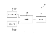
図7は、ドアミラーシステム70を示すブロック図である。
同図に示すように、上述したカメラユニット30は、ドアミラーシステム70の一部を構成している。ドアミラーシステム70は、カメラユニット30の他に、ミラーハウジング2内に収納されている制御部28、車体101の車室内に設けられたモニタ71を備えている。モニタ71は、車室内の運転者が視認し易い任意の箇所に配置されている。これらカメラユニット30及びモニタ71は、制御部28に接続されている。
(Door mirror system)
FIG. 7 is a block diagram showing the
As shown in the figure, the above-mentioned
(ドアミラーシステムの動作)
次に、ドアミラーシステム70の動作について説明する。
まず、車体101の側部後方に障害物がなく、且つ、カットフィルター9や各カメラ31,32のレンズ31a,32aに雨滴や汚れ等が付着していない場合について説明する。
図7に示すように、カメラユニット30によって撮像された画像は、信号として制御部28に出力される。さらに、制御部28は、カメラユニット30から受信した信号を処理し、この処理した信号をモニタ71に出力する。モニタ71は、制御部28から受信した信号に基づいて、メインカメラ31によって撮像された画像を映し出す。運転者は、モニタ71に映し出される画像を視認することにより、車体101の側部後方の状況を確認できる。
(Operation of door mirror system)
Next, the operation of the
First, a case where there is no obstacle behind the side portion of the
As shown in FIG. 7, the image captured by the
ここで、各カメラ31,32、特にメインカメラ31は、カットフィルター9を介して車体101の側部後方を撮像するので、外部から各カメラ31,32に入光される光は、所定波長域が減衰される。しかも、プロテクター40の遮光部第1遮光部42aによって、レンズ31aに過剰な光が入射してしまうのが防止されている。このため、例えば逆光時にメインカメラ31による撮像が白くぼやける等して不鮮明になることが防止される。
Here, since the
次に、カットフィルター9や各カメラ31,32のレンズ31a,32aに雨滴や汚れ等が付着している場合(以下、汚れ付着時の場合という)について説明する。
図8は、汚れ付着時のドアミラーシステム70のフローチャートである。
図7、図8に示すように、制御部28は、カットフィルター9に雨滴や塵が付着したりカットフィルター9やサブカメラ32のレンズ32aが曇ったりすることを(ステップST11)、サブカメラ32によって検知したか否かを判断する(ステップST12)。
ここで、メインカメラ31は、サブカメラ32と同じ状況下に配置されていることから、メインカメラ31のレンズ31aの状態は、サブカメラ32のレンズ32aの状態と同視し得るものとしている。すなわち、メインカメラ31のレンズ31aが曇ったか否かの判断は、サブカメラ32のレンズ32aが曇ったか否かの判断により行っている。
Next, a case where raindrops, dirt, etc. are attached to the
FIG. 8 is a flowchart of the
As shown in FIGS. 7 and 8, the
Here, since the
ステップST12の判断が「No」、つまり、カットフィルター9に雨滴や塵が付着したり、カットフィルター9やサブカメラ32のレンズ32aが曇ったりしたことをサブカメラ32によって検知していない場合、再びステップST12の判断を行う。
一方、ステップST12の判断が「Yes」、つまり、カットフィルター9に雨滴や塵が付着したり、カットフィルター9やサブカメラ32のレンズ32aが曇ったりしたことをサブカメラ32によって検知した場合、制御部28は、不図示の汚れ除去手段を駆動させる(ステップST13)。
If the determination in step ST12 is "No", that is, if the
On the other hand, when the determination in step ST12 is "Yes", that is, when the
汚れ除去手段としては、例えば雨滴や雪、曇り等に対しては、ミラーハウジング2内にヒーターを設け、このヒーターを作動させることにより、雨滴や雪、曇りを除去する。また、例えば塵や泥等に対しては、ミラーハウジング2にワイパ装置を設け、このワイパ装置を作動させることにより、カットフィルター9の表面9bを払拭する。
As a dirt removing means, for example, for raindrops, snow, cloudiness, etc., a heater is provided in the
そして、制御部28は、メインカメラ31の撮像が鮮明か否かの判断を行う(ステップST14)。
ステップST14の判断が「No」、つまり、制御部28によってメインカメラ31の撮像がまだ不鮮明であると判断された場合、汚れ除去装置はONされたままになる。また、再び、ステップST14の判断を行う。
一方、ステップST14の判断が「Yes」、つまり、制御部28によってメインカメラ31の撮像が鮮明になったと判断された場合、汚れ除去装置がOFFされてドアミラーシステム70の処理が完了する。
Then, the
If the determination in step ST14 is "No", that is, if the
On the other hand, when the determination in step ST14 is "Yes", that is, when the
次に、図7、図9に基づいて、車体101の側部後方に障害物がある場合(以下、障害物がある場合という)について説明する。
図9は、障害物がある場合のドアミラーシステム70のフローチャートである。
図7、図9に示すように、制御部28は、障害物があるかを(ステップST21)、サブカメラ32によって検知したか否かを判断する(ステップST22)。
Next, a case where there is an obstacle behind the side portion of the vehicle body 101 (hereinafter, referred to as a case where there is an obstacle) will be described with reference to FIGS. 7 and 9.
FIG. 9 is a flowchart of the
As shown in FIGS. 7 and 9, the
ステップST22の判断が「No」、つまり、障害物がない場合、再びステップST22の判断を行う。
一方、ステップST22の判断が「Yes」、つまり、障害物がある場合、制御部28は、不図示の注意喚起装置を駆動させる(ステップST23)。
If the determination in step ST22 is "No", that is, there is no obstacle, the determination in step ST22 is performed again.
On the other hand, when the determination in step ST22 is "Yes", that is, when there is an obstacle, the
注意喚起装置としては、例えば、乗員へ音声で危険を知らせる警報器であったり、サブカメラ32の映像を表示させるモニタであったりしてもよい。モニタは、メインカメラ31の映像を表示するモニタ71と同じものでもよい。モニタ71と同じ場合には、通常時はメインカメラ31の映像のみを映し、障害物がある場合には画角が変更され、メインカメラ31とサブカメラ32の2つのカメラ31,32の画角を合成した広い画角の映像が表示されることが望ましい。
The alert device may be, for example, an alarm that notifies the occupant of the danger by voice, or a monitor that displays an image of the
そして、制御部28は、サブカメラに32によって障害物が検知されなくなったか否かの判断を行う(ステップST24)。
ステップST24の判断が「No」、つまり、サブカメラに32によってまだ障害物が検知されていると判断された場合、注意喚起装置はONされたままになる。また、再び、ステップST24の判断を行う。
一方、ステップST24の判断が「Yes」、つまり、サブカメラに32によって障害物が検知されなくなったと判断された場合、注意喚起装置がOFFされてドアミラーシステム70の処理が完了する。
Then, the
If the determination in step ST24 is "No", that is, if it is determined that an obstacle is still detected by the
On the other hand, when the determination in step ST24 is "Yes", that is, when it is determined that the sub camera does not detect an obstacle by 32, the alert device is turned off and the processing of the
なお、車体101の側部後方に障害物があり、且つ、カットフィルター9や各カメラ31,32のレンズ31a,32aに雨滴や汚れ等が付着している場合については、汚れ除去装置と注意喚起装置とのどちらを優先して駆動させるかは任意に設定してよい。
If there is an obstacle behind the side of the
このように、上述の実施形態では、ハウジング本体4内に、カメラユニット30が収納されている。カメラユニット30は、メインカメラ31とサブカメラ32の2つのカメラ31,32により構成されている。このため、メインカメラ31を車体101の側部後方の撮像用として利用し、サブカメラ32をセンサ用として利用するように、両カメラ31,32を使い分けることで、ドアミラーシステム70の制御の複雑化を抑えることができる。また、使用するカメラ31,32の切り替えにより撮像範囲A1,A2を容易に変更できる。さらに、サブカメラ32の検出結果に基づいて、各カメラ31,32のレンズ31a,32aやカットフィルター9の付着物等を払拭することにより、メインカメラ31によって車体後方を確実に鮮明に撮像することが可能になる。
As described above, in the above-described embodiment, the
また、ミラーハウジング2の後方の開口部6aには、カットフィルター9が嵌め込まれている。このため、このカットフィルター9によって、カメラユニット30に入射される光量を減少できる。よって、カメラユニット30を高感度化した場合であっても逆光時等に撮像が不鮮明になってしまうことを抑制できる。
A
また、ミラーハウジング2は、車体101から右方に向かって突出する支持部3と、支持部3の先端に一体成形されたハウジング本体4と、により構成されている。このため、ドアミラー1の部品点数を減少でき、ドアミラー1の製造コストを低減できる。
また、外観上ドアミラー1をすっきり見せることができ、ドアミラー1の意匠性を高めることができる。
Further, the
In addition, the door mirror 1 can be made to look neat in appearance, and the design of the door mirror 1 can be enhanced.
ドアミラー1は、ミラーハウジング2の車体101側にサブカメラ32が配置され、ミラーハウジング2の車体101側とは反対側の右側にメインカメラ31が配置されている。このため、サブカメラ32の撮像範囲A2は、メインカメラ31の撮像範囲A1と比較して車幅方向外側を向いているが、サブカメラ32にリム部6が映り込んでしまことがない。この結果、サブカメラ32によって、車幅方向外側のできる限り広い範囲を撮像することが可能になる。
また、サブカメラ32の撮像範囲A2が、メインカメラ31の撮像範囲A1と比較して車幅方向外側を向いていることにより、サブカメラ32によって車幅方向外側のできる限り広い範囲を撮像できる。このため、サブカメラ32を障害物検知用として使用する場合、障害物などの検知精度を高めることが可能になる。
In the door mirror 1, the
Further, since the imaging range A2 of the
また、メインカメラ31は、サブカメラ32よりも上方に配置されている。そして、2つのカメラ31,32は、車体101の高さ方向(上下方向)からみて一部が重なるように配置されている。このため、ハウジング本体4の車幅方向の長さを短く設定でき、車体101の車幅が増大してしまうことを抑制できる。
ところで、カメラユニット30に接続されるハーネスやドアミラー1の格納装置などをミラーハウジング2の支持部3内に収容する場合、支持部3を車体101の高さ方向に拡大する必要がある。しかしながら、各カメラ31,32を、車体の高さ方向からみて一部が重なるように配置することにより、ハウジング本体4を高さ方向へ大きく形成し、ドアミラー1全体を凹凸のない滑らかな形状に設計できる。このため、ドアミラー1の意匠性を高めることができる。
Further, the
By the way, when the harness connected to the
また、カットフィルター9のフィルター膜12は、光をハウジング本体4の外部へ反射可能に構成されているので、鏡として利用することが可能である。このため、カットフィルター9の傾き角θ2を調整することにより(例えば、傾き角θ2を15°〜30°に設定)、運転者は、カットフィルター9を利用して車体101の後方を確認することができる。よって、仮にカメラユニット30に不具合が生じた場合であっても、カットフィルター9をドアミラー1として用いることにより車体後方を視認でき、ドアミラー1のフェールセーフ機能を高めることができる。
Further, since the
しかも、例えば、センサとして用いるサブカメラ32をメインカメラ31よりも車体101側に配置すれば、ハウジング本体4を車体側に傾けた場合であっても、サブカメラ32によって車幅方向外側のできる限り広い範囲を撮像できる(図3における撮像範囲A2参照)ので、センサ用としてのサブカメラ32の機能を損なうことがない。このため、ハウジング本体4の傾き調整範囲をできる限り拡げることができるので、カットフィルター9を、車体後方確認用の鏡として確実に利用できる。
Moreover, for example, if the
また、ミラーハウジング2内のカットフィルター9とカメラユニット30との間に、プロテクター40が設けられている。プロテクター40は、カットフィルター9の背面9aを覆うように板状に形成された本体部41と、この本体部41から各カメラ31,32のレンズ31a,32aの周辺を覆うように略円筒状に形成された各遮光部42a,42bと、を有している。このため、各遮光部42a,42bにより各カメラ31,32のレンズ31a,32aに過剰な光が入射してしまうのを、より確実に防止できる。また、本体部41を透過不能な材料で形成したり、塗料で塗布したりすることにより、外部からハウジング本体4の内部を見えにくくすることができ、ドアミラー1の意匠性を向上できる。
Further, a
なお、本発明は上述の実施形態に限られるものではなく、本発明の趣旨を逸脱しない範囲において、上述の実施形態に種々の変更を加えたものを含む。
例えば、上述の実施形態では、カメラユニット30は、メインカメラ31とサブカメラ32の2つのカメラ31,32により構成されている場合について説明した。しかしながら、これに限られるものではなく、2つ以上の複数のカメラによりカメラユニット30を構成してもよい。この場合、1つのカメラをメインカメラ31とし、その他のカメラをサブカメラ32とし、各サブカメラ32を汚れ付着を検知するセンサ用と、障害物を検知するセンサ用とで使い分けてもよい。また、2つ以上のカメラをメインカメラ31として、例えば駐車時等に車体101の側部後方の撮像範囲を変更するように構成してもよい。
The present invention is not limited to the above-described embodiment, and includes various modifications of the above-described embodiment without departing from the spirit of the present invention.
For example, in the above-described embodiment, the case where the
また、カメラユニット30に高感度カメラを採用し、ハイビームや無灯火の後続車を検知し、モニタ71に表示する映像を、運転手が見やすいように加工したり、運転手に注意喚起したりするようにしてもよい。
In addition, a high-sensitivity camera is used for the
また、上述の実施形態では、ミラーハウジング2のリム部6の傾き角θ1を15°〜30°の範囲に設定し、リム部6の開口部6aに嵌め込まれるカットフィルター9の傾き角θ2も、傾き角θ1と同様の角度に設定した場合について説明した。しかしながら、これに限られるものではなく、リム部6の傾き角θ1とカットフィルター9の傾き角θ2は、それぞれ任意の角度に設定することができる。
Further, in the above-described embodiment, the inclination angle θ1 of the
また、上述の実施形態では、ミラーハウジング2のハウジング本体4に、本体側ベース部61と本体側カバー62との間で、且つ前側面から右側面に至る間に、サイドターンランプ80を設けた場合について説明した。しかしながら、これに限られるものではなく、サイドターンランプ80を設けなくてもよい。
Further, in the above-described embodiment, the housing
1…ドアミラー、2…ミラーハウジング、3…支持部、4…ハウジング本体、9…カットフィルター、9b…表面(一面)、30…カメラユニット、31…メインカメラ(第1カメラ)、31a,32a…レンズ、32…サブカメラ(第2カメラ)、40…プロテクター、41…本体部、42a…第1遮光部、42b…第2遮光部、101…車体、A1,A2…撮像範囲 1 ... Door mirror, 2 ... Mirror housing, 3 ... Support, 4 ... Housing body, 9 ... Cut filter, 9b ... Surface (one side), 30 ... Camera unit, 31 ... Main camera (first camera), 31a, 32a ... Lens, 32 ... Sub camera (second camera), 40 ... Protector, 41 ... Main body, 42a ... First shading part , 42b ... Second shading part , 101 ... Body, A1, A2 ... Imaging range
Claims (7)
前記ハウジング本体内に収納され、前記車体の進行方向後方を撮像するカメラユニットと、
前記カメラユニットに入射される光量を減少するカットフィルターと、を備え、
前記カメラユニットは、
前記車体の一部を含む前記進行方向後方を撮像する第1カメラと、
前記第1カメラの撮像範囲よりも前記車体の車幅方向外側を含む範囲を撮像する第2カメラと、
の少なくとも2つのカメラを有し、
前記第1カメラおよび前記第2カメラは、前記車体の高さ方向からみて一部が重なるように配置され、且つ前記第1カメラおよび前記第2カメラのうち上方に配置されたカメラは、前記第1カメラおよび前記第2カメラのうち下方に配置されたカメラよりも前記車体の車幅方向外側に配置されている
ことを特徴とするドアミラー。 The housing body provided on the side of the car body and
A camera unit that is housed in the housing body and images the rear of the vehicle body in the traveling direction.
A cut filter that reduces the amount of light incident on the camera unit is provided.
The camera unit is
A first camera that captures the rear part of the vehicle body in the traveling direction,
A second camera that captures a range including the outside of the vehicle body in the vehicle width direction from the imaging range of the first camera.
Have at least two cameras,
The first camera and the second camera are arranged so as to partially overlap each other when viewed from the height direction of the vehicle body, and the camera arranged above the first camera and the second camera is the first camera. A door mirror characterized in that it is arranged outside the vehicle body in the vehicle width direction with respect to a camera arranged below the one camera and the second camera .
前記支持部の前記車体とは反対側の先端に、前記ハウジング本体を一体成形したことを特徴とする請求項1に記載のドアミラー。 A support portion is provided on the side portion of the vehicle body.
The door mirror according to claim 1, wherein the housing body is integrally molded at the tip of the support portion on the side opposite to the vehicle body.
ことを特徴とする請求項1または請求項2に記載のドアミラー。 The door mirror according to claim 1 or 2, wherein the second camera captures and detects an deposit on at least one of the lens of the second camera and the cut filter.
前記第1カメラは前記第2カメラよりも前記車体の車幅方向外側に設けられていることを特徴とする請求項1から請求項3の何れか1項に記載のドアミラー。 The second camera is provided on the vehicle body side and is provided.
Wherein the first camera door mirror according to any one of claims 1 to 3, characterized in that provided in the vehicle width direction outer side of the vehicle body than the second camera.
ことを特徴とする請求項1から請求項4の何れか1項に記載のドアミラー。 The cut filter, door mirror according to any one of claims 1 to 4, characterized in that one side the one surface is processed into a mirror-like is disposed toward the traveling direction rearward of the vehicle body ..
前記プロテクターは、
板状の本体部と、
前記本体部から突設され、前記第1カメラのレンズの周辺を覆う第1遮光部、および前記第2カメラのレンズの周辺を覆う第2遮光部と、
を有する
ことを特徴とする請求項1から請求項5の何れか1項に記載のドアミラー。 A protector is provided between the cut filter and the camera unit.
The protector is
Plate-shaped body and
Said protruding from the main body portion, a first light-shielding portion covering the periphery of the first camera lens, and a second light-shielding portion covering the periphery of the lenses of the second camera,
Door mirror according to claims 1 to any one of claims 5, characterized in that it comprises a.
ことを特徴とする請求項6に記載のドアミラー。The door mirror according to claim 6, wherein the door mirror is characterized in that.
Priority Applications (5)
| Application Number | Priority Date | Filing Date | Title |
|---|---|---|---|
| JP2017175908A JP6815957B2 (en) | 2017-09-13 | 2017-09-13 | door mirror |
| EP18806844.9A EP3632745B1 (en) | 2017-05-23 | 2018-04-27 | Door mirror |
| CN201880033151.3A CN110709283B (en) | 2017-05-23 | 2018-04-27 | Reflector |
| US16/612,914 US11034300B2 (en) | 2017-05-23 | 2018-04-27 | Door mirror |
| PCT/JP2018/017196 WO2018216434A1 (en) | 2017-05-23 | 2018-04-27 | Door mirror |
Applications Claiming Priority (1)
| Application Number | Priority Date | Filing Date | Title |
|---|---|---|---|
| JP2017175908A JP6815957B2 (en) | 2017-09-13 | 2017-09-13 | door mirror |
Publications (2)
| Publication Number | Publication Date |
|---|---|
| JP2019051769A JP2019051769A (en) | 2019-04-04 |
| JP6815957B2 true JP6815957B2 (en) | 2021-01-20 |
Family
ID=66014130
Family Applications (1)
| Application Number | Title | Priority Date | Filing Date |
|---|---|---|---|
| JP2017175908A Active JP6815957B2 (en) | 2017-05-23 | 2017-09-13 | door mirror |
Country Status (1)
| Country | Link |
|---|---|
| JP (1) | JP6815957B2 (en) |
Families Citing this family (3)
| Publication number | Priority date | Publication date | Assignee | Title |
|---|---|---|---|---|
| JP7401172B2 (en) * | 2019-08-09 | 2023-12-19 | フィコミロース, エセ. ア. ウ. | Vehicle camera module |
| JP7372822B2 (en) * | 2019-11-26 | 2023-11-01 | 株式会社ペンストン | vehicle side mirror |
| KR20230091870A (en) | 2020-10-23 | 2023-06-23 | 소니그룹주식회사 | Camera module, information processing system, information processing method and information processing device |
Family Cites Families (5)
| Publication number | Priority date | Publication date | Assignee | Title |
|---|---|---|---|---|
| JPH11327016A (en) * | 1998-05-19 | 1999-11-26 | Sony Corp | Lens protector and peripheral photographing device using the same |
| JP4088100B2 (en) * | 2002-05-14 | 2008-05-21 | 株式会社村上開明堂 | Rearview mirror with built-in camera |
| JP2007112368A (en) * | 2005-10-24 | 2007-05-10 | Tgal:Kk | Vehicular rear view checking camera device |
| JP2007208865A (en) * | 2006-02-06 | 2007-08-16 | Clarion Co Ltd | System for detecting camera state |
| JP5178085B2 (en) * | 2007-08-07 | 2013-04-10 | 株式会社村上開明堂 | Rearview mirror with imaging device |
-
2017
- 2017-09-13 JP JP2017175908A patent/JP6815957B2/en active Active
Also Published As
| Publication number | Publication date |
|---|---|
| JP2019051769A (en) | 2019-04-04 |
Similar Documents
| Publication | Publication Date | Title |
|---|---|---|
| US6768092B2 (en) | Sensor in car window | |
| US12177608B2 (en) | Vehicular driver monitoring system | |
| US10384610B2 (en) | Rearview vision system for vehicle | |
| JP5936288B2 (en) | Vehicle imaging device | |
| US7310190B2 (en) | Vehicle imaging system with windshield condition determination | |
| JP6815957B2 (en) | door mirror | |
| US20060034002A1 (en) | Refractive block and imaging systems | |
| CN110998650B (en) | Active looking-around system with automatic cleaning mechanism | |
| JP6013922B2 (en) | Vehicle camera device | |
| JP2008157924A (en) | Photosensitive sensor in automobile field | |
| JP2014061808A (en) | Rearward visual recognition apparatus | |
| JP4058983B2 (en) | In-vehicle omnidirectional camera | |
| JP2020059453A (en) | Rearward visual recognition device | |
| US11034300B2 (en) | Door mirror | |
| JP2005284485A (en) | Dead angle visible device for vehicle | |
| JP2016218044A (en) | Window surface detection sensor | |
| JP2017061216A (en) | On-board imaging system, vehicle and imaging method | |
| JP4231962B2 (en) | Vehicle monitoring device | |
| US9569677B2 (en) | Device and method for directing radiation in the direction of an optical element of an image sensing device of a vehicle | |
| JP2001318398A (en) | Vehicle periphery recognition device | |
| JP6922699B2 (en) | Wind surface detection sensor | |
| JP2006157634A (en) | In-vehicle imaging system | |
| JP2011005891A (en) | Vehicular front side view monitoring device | |
| JP2022147484A (en) | sunshade | |
| JP2008201348A (en) | Vehicle outside visual recognition device |
Legal Events
| Date | Code | Title | Description |
|---|---|---|---|
| A621 | Written request for application examination |
Free format text: JAPANESE INTERMEDIATE CODE: A621 Effective date: 20200317 |
|
| A131 | Notification of reasons for refusal |
Free format text: JAPANESE INTERMEDIATE CODE: A131 Effective date: 20200818 |
|
| A521 | Request for written amendment filed |
Free format text: JAPANESE INTERMEDIATE CODE: A523 Effective date: 20201012 |
|
| TRDD | Decision of grant or rejection written | ||
| A01 | Written decision to grant a patent or to grant a registration (utility model) |
Free format text: JAPANESE INTERMEDIATE CODE: A01 Effective date: 20201208 |
|
| A61 | First payment of annual fees (during grant procedure) |
Free format text: JAPANESE INTERMEDIATE CODE: A61 Effective date: 20201223 |
|
| R150 | Certificate of patent or registration of utility model |
Ref document number: 6815957 Country of ref document: JP Free format text: JAPANESE INTERMEDIATE CODE: R150 |
|
| S111 | Request for change of ownership or part of ownership |
Free format text: JAPANESE INTERMEDIATE CODE: R313113 |
|
| R350 | Written notification of registration of transfer |
Free format text: JAPANESE INTERMEDIATE CODE: R350 |
|
| R250 | Receipt of annual fees |
Free format text: JAPANESE INTERMEDIATE CODE: R250 |
|
| R250 | Receipt of annual fees |
Free format text: JAPANESE INTERMEDIATE CODE: R250 |