[go: up one dir, main page]

JP6812721B2 - Ophthalmic equipment - Google Patents

Ophthalmic equipment Download PDF

Info

Publication number
JP6812721B2
JP6812721B2 JP2016191816A JP2016191816A JP6812721B2 JP 6812721 B2 JP6812721 B2 JP 6812721B2 JP 2016191816 A JP2016191816 A JP 2016191816A JP 2016191816 A JP2016191816 A JP 2016191816A JP 6812721 B2 JP6812721 B2 JP 6812721B2
Authority
JP
Japan
Prior art keywords
suction
waste liquid
unit
path
lqw
Prior art date
Legal status (The legal status is an assumption and is not a legal conclusion. Google has not performed a legal analysis and makes no representation as to the accuracy of the status listed.)
Active
Application number
JP2016191816A
Other languages
Japanese (ja)
Other versions
JP2018051045A (en
Inventor
寿敏 加藤
寿敏 加藤
鈴木 信雄
信雄 鈴木
Current Assignee (The listed assignees may be inaccurate. Google has not performed a legal analysis and makes no representation or warranty as to the accuracy of the list.)
Nidek Co Ltd
Original Assignee
Nidek Co Ltd
Priority date (The priority date is an assumption and is not a legal conclusion. Google has not performed a legal analysis and makes no representation as to the accuracy of the date listed.)
Filing date
Publication date
Application filed by Nidek Co Ltd filed Critical Nidek Co Ltd
Priority to JP2016191816A priority Critical patent/JP6812721B2/en
Priority to EP17193713.9A priority patent/EP3300704B1/en
Publication of JP2018051045A publication Critical patent/JP2018051045A/en
Application granted granted Critical
Publication of JP6812721B2 publication Critical patent/JP6812721B2/en
Active legal-status Critical Current
Anticipated expiration legal-status Critical

Links

Images

Classifications

    • AHUMAN NECESSITIES
    • A61MEDICAL OR VETERINARY SCIENCE; HYGIENE
    • A61FFILTERS IMPLANTABLE INTO BLOOD VESSELS; PROSTHESES; DEVICES PROVIDING PATENCY TO, OR PREVENTING COLLAPSING OF, TUBULAR STRUCTURES OF THE BODY, e.g. STENTS; ORTHOPAEDIC, NURSING OR CONTRACEPTIVE DEVICES; FOMENTATION; TREATMENT OR PROTECTION OF EYES OR EARS; BANDAGES, DRESSINGS OR ABSORBENT PADS; FIRST-AID KITS
    • A61F9/00Methods or devices for treatment of the eyes; Devices for putting in contact-lenses; Devices to correct squinting; Apparatus to guide the blind; Protective devices for the eyes, carried on the body or in the hand
    • A61F9/007Methods or devices for eye surgery
    • A61F9/00736Instruments for removal of intra-ocular material or intra-ocular injection, e.g. cataract instruments
    • AHUMAN NECESSITIES
    • A61MEDICAL OR VETERINARY SCIENCE; HYGIENE
    • A61MDEVICES FOR INTRODUCING MEDIA INTO, OR ONTO, THE BODY; DEVICES FOR TRANSDUCING BODY MEDIA OR FOR TAKING MEDIA FROM THE BODY; DEVICES FOR PRODUCING OR ENDING SLEEP OR STUPOR
    • A61M1/00Suction or pumping devices for medical purposes; Devices for carrying-off, for treatment of, or for carrying-over, body-liquids; Drainage systems
    • A61M1/71Suction drainage systems
    • A61M1/72Cassettes forming partially or totally the fluid circuit
    • AHUMAN NECESSITIES
    • A61MEDICAL OR VETERINARY SCIENCE; HYGIENE
    • A61MDEVICES FOR INTRODUCING MEDIA INTO, OR ONTO, THE BODY; DEVICES FOR TRANSDUCING BODY MEDIA OR FOR TAKING MEDIA FROM THE BODY; DEVICES FOR PRODUCING OR ENDING SLEEP OR STUPOR
    • A61M1/00Suction or pumping devices for medical purposes; Devices for carrying-off, for treatment of, or for carrying-over, body-liquids; Drainage systems
    • A61M1/71Suction drainage systems
    • A61M1/74Suction control
    • AHUMAN NECESSITIES
    • A61MEDICAL OR VETERINARY SCIENCE; HYGIENE
    • A61MDEVICES FOR INTRODUCING MEDIA INTO, OR ONTO, THE BODY; DEVICES FOR TRANSDUCING BODY MEDIA OR FOR TAKING MEDIA FROM THE BODY; DEVICES FOR PRODUCING OR ENDING SLEEP OR STUPOR
    • A61M1/00Suction or pumping devices for medical purposes; Devices for carrying-off, for treatment of, or for carrying-over, body-liquids; Drainage systems
    • A61M1/80Suction pumps
    • A61M1/804Suction pumps using Laval or Venturi jet pumps
    • AHUMAN NECESSITIES
    • A61MEDICAL OR VETERINARY SCIENCE; HYGIENE
    • A61MDEVICES FOR INTRODUCING MEDIA INTO, OR ONTO, THE BODY; DEVICES FOR TRANSDUCING BODY MEDIA OR FOR TAKING MEDIA FROM THE BODY; DEVICES FOR PRODUCING OR ENDING SLEEP OR STUPOR
    • A61M3/00Medical syringes, e.g. enemata; Irrigators
    • A61M3/02Enemata; Irrigators
    • A61M3/0201Cassettes therefor
    • AHUMAN NECESSITIES
    • A61MEDICAL OR VETERINARY SCIENCE; HYGIENE
    • A61MDEVICES FOR INTRODUCING MEDIA INTO, OR ONTO, THE BODY; DEVICES FOR TRANSDUCING BODY MEDIA OR FOR TAKING MEDIA FROM THE BODY; DEVICES FOR PRODUCING OR ENDING SLEEP OR STUPOR
    • A61M3/00Medical syringes, e.g. enemata; Irrigators
    • A61M3/02Enemata; Irrigators
    • A61M3/0233Enemata; Irrigators characterised by liquid supply means, e.g. from pressurised reservoirs
    • A61M3/0241Enemata; Irrigators characterised by liquid supply means, e.g. from pressurised reservoirs the liquid being supplied by gravity
    • AHUMAN NECESSITIES
    • A61MEDICAL OR VETERINARY SCIENCE; HYGIENE
    • A61MDEVICES FOR INTRODUCING MEDIA INTO, OR ONTO, THE BODY; DEVICES FOR TRANSDUCING BODY MEDIA OR FOR TAKING MEDIA FROM THE BODY; DEVICES FOR PRODUCING OR ENDING SLEEP OR STUPOR
    • A61M2205/00General characteristics of the apparatus
    • A61M2205/12General characteristics of the apparatus with interchangeable cassettes forming partially or totally the fluid circuit
    • A61M2205/123General characteristics of the apparatus with interchangeable cassettes forming partially or totally the fluid circuit with incorporated reservoirs
    • AHUMAN NECESSITIES
    • A61MEDICAL OR VETERINARY SCIENCE; HYGIENE
    • A61MDEVICES FOR INTRODUCING MEDIA INTO, OR ONTO, THE BODY; DEVICES FOR TRANSDUCING BODY MEDIA OR FOR TAKING MEDIA FROM THE BODY; DEVICES FOR PRODUCING OR ENDING SLEEP OR STUPOR
    • A61M2210/00Anatomical parts of the body
    • A61M2210/06Head
    • A61M2210/0612Eyes

Landscapes

  • Health & Medical Sciences (AREA)
  • Heart & Thoracic Surgery (AREA)
  • General Health & Medical Sciences (AREA)
  • Veterinary Medicine (AREA)
  • Engineering & Computer Science (AREA)
  • Biomedical Technology (AREA)
  • Public Health (AREA)
  • Life Sciences & Earth Sciences (AREA)
  • Animal Behavior & Ethology (AREA)
  • Anesthesiology (AREA)
  • Hematology (AREA)
  • Vascular Medicine (AREA)
  • Ophthalmology & Optometry (AREA)
  • Nuclear Medicine, Radiotherapy & Molecular Imaging (AREA)
  • Surgery (AREA)
  • External Artificial Organs (AREA)

Description

本開示は、眼科手術に使用される眼科装置に関する。 The present disclosure relates to ophthalmic devices used in ophthalmic surgery.

特許文献1には、ハンドピースに繋げるポンプを、セレクタにより蠕動ポンプまたはベンチュリポンプに切り替え可能な手術カセット装置が開示されている。 Patent Document 1 discloses a surgical cassette device in which a pump connected to a handpiece can be switched to a peristaltic pump or a Venturi pump by a selector.

米国特許第9005157号U.S. Pat. No. 900157

特許文献1に開示される手術カセット装置においては、蠕動ポンプとベンチュリポンプが、セレクタによりハンドピースとの接続が切り替えられる独立した経路に設けられ、一方のポンプの使用時は他方のポンプを停止させている。そのため、ハンドピースに繋げるポンプを切り替えるときには、ポンプの特性の違いから、ハンドピースの吸引口の吸引圧が変化してしまう恐れがあり、吸引中の自由な切り替えは難しい。 In the surgical cassette device disclosed in Patent Document 1, the peristaltic pump and the Venturi pump are provided in an independent path in which the connection with the handpiece is switched by the selector, and when one pump is used, the other pump is stopped. ing. Therefore, when switching the pump connected to the handpiece, the suction pressure at the suction port of the handpiece may change due to the difference in the characteristics of the pump, and it is difficult to freely switch during suction.

そこで、本開示は、吸引中の継ぎ目のない吸引部(ポンプ)の切り替えを可能とし、術者にとってより使い易く、効率の良い手術が可能となる眼科装置を提供することを目的とする。 Therefore, it is an object of the present disclosure to provide an ophthalmic apparatus capable of switching a seamless suction portion (pump) during suction, making it easier for an operator to use and enabling efficient surgery.

本開示における典型的な実施形態が提供する眼科装置は、患者眼から眼内組織を含む液体を吸引する吸引口と、前記吸引口にて吸引された前記眼内組織を含む液体が貯留される貯留部と、前記貯留部内に前記眼内組織を含む液体を取り入れるために前記貯留部内の気体を吸引して前記貯留部内の圧力を下げる第1吸引部と、前記吸引口から前記貯留部を介して形成される第1経路と、前記吸引口から前記貯留部を迂回して形成される第2経路と、前記第1経路と前記第2経路に接続し、前記第1経路と前記第2経路に送られる前記眼内組織を含む液体を吸引する第2吸引部と、前記第2吸引部から送られる前記眼内組織を含む液体を回収する廃液部と、前記吸引口と前記第2吸引部とを繋ぐ経路を前記第1経路または前記第2経路に切り替える切替部と、を有し、前記第2吸引部は、1つの吸引部を共用して、前記第1経路に送られる前記眼内組織を含む液体の吸引と、前記第2経路に送られる前記眼内組織を含む液体の吸引とを行うものであり、前記切替部により前記吸引口と前記第2吸引部とを繋ぐ経路を前記第1経路に設定しているときに、前記第2吸引部により前記貯留部内の前記眼内組織を含む液体を前記廃液部に送り、前記切替部により前記吸引口と前記第2吸引部とを繋ぐ経路を前記第1経路から前記第2経路に切り替えるときに、前記第2吸引部の動作を維持すること、を特徴とする。 The ophthalmic apparatus provided by the typical embodiment in the present disclosure stores a suction port for sucking a liquid containing the intraocular tissue from the patient's eye and a liquid containing the intraocular tissue sucked by the suction port. The storage unit, the first suction unit that sucks the gas in the storage unit to reduce the pressure in the storage unit in order to take in the liquid containing the intraocular tissue into the storage unit, and the suction port via the storage unit. The first path formed by the suction port, the second path formed by bypassing the storage portion from the suction port, the first path and the second path connected to the first path and the second path. A second suction unit that sucks the liquid containing the intraocular tissue sent to the second suction unit, a waste liquid unit that collects the liquid containing the intraocular tissue sent from the second suction unit, the suction port, and the second suction unit. the path connecting the door have a, a switching unit for switching to the first path or the second path, the second suction unit may share a single suction unit, in the eye to be sent to the first path The suction of the liquid containing the tissue and the suction of the liquid containing the intraocular tissue sent to the second path are performed, and the path connecting the suction port and the second suction portion by the switching portion is described. When the first path is set, the second suction unit sends the liquid containing the intraocular tissue in the storage unit to the waste liquid unit, and the switching unit connects the suction port and the second suction unit. It is characterized in that the operation of the second suction unit is maintained when the connecting path is switched from the first path to the second path .

本開示の眼科装置によれば、吸引中の継ぎ目のない吸引部の切り替えを可能とし、術者にとってより使い易く、効率の良い手術が可能となる。 According to the ophthalmic apparatus of the present disclosure, it is possible to switch the suction portion seamlessly during suction, which makes it easier for the operator to use and enables efficient surgery.

眼科装置の外観図である。It is an external view of an ophthalmic apparatus. 図1の眼科装置の概略構成図であり、第1吸引モードにおける状態を示す図である。It is a schematic block diagram of the ophthalmic apparatus of FIG. 1, and is the figure which shows the state in the 1st suction mode. 図1の眼科装置の制御部を説明する概略構成図である。It is a schematic block diagram explaining the control part of the ophthalmic apparatus of FIG. 図1の眼科装置の概略構成図であり、第2吸引モードにおける状態を示す図である。It is a schematic block diagram of the ophthalmic apparatus of FIG. 1, and is the figure which shows the state in the 2nd suction mode.

本実施形態の眼科装置1について説明する。眼科装置1は、例えば、白内障硝子体手術に使用されるものである。本実施形態では、詳しくは後述するように、患者眼Eから廃液LQWを吸引する吸引モードとして、患者眼Eから廃液LQWを吸引する吸引源を第1吸引部29とする第1吸引モード、または、患者眼Eから廃液LQWを吸引する吸引源を第2吸引部31とする第2吸引モードに切り替えることができる。そこで、まず、眼科装置1の全体的な構成について説明をした後、本実施形態の吸引モードについて説明する。 The ophthalmic apparatus 1 of the present embodiment will be described. The ophthalmic apparatus 1 is used, for example, for cataract vitreous surgery. In the present embodiment, as will be described in detail later, as a suction mode for sucking the waste liquid LQW from the patient's eye E, a first suction mode in which the suction source for sucking the waste liquid LQW from the patient's eye E is the first suction unit 29, or The suction source for sucking the waste liquid LQW from the patient's eye E can be switched to the second suction mode in which the second suction unit 31 is used. Therefore, first, the overall configuration of the ophthalmic apparatus 1 will be described, and then the suction mode of the present embodiment will be described.

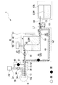
図1と図2に示すように、本実施形態の眼科装置1は、一例として、本体11とカセット12を有している。本体11は、モニタ21と接続パネル22を備えている。モニタ21に、一例として、手術条件の設定画面や手術装置の駆動結果である手術結果の一覧等が表示される。接続パネル22に、一例として、手術用ハンドピース13のケーブル等が接続される複数のコネクタが設けられている。 As shown in FIGS. 1 and 2, the ophthalmic apparatus 1 of the present embodiment has a main body 11 and a cassette 12 as an example. The main body 11 includes a monitor 21 and a connection panel 22. As an example, the monitor 21 displays a screen for setting surgical conditions, a list of surgical results that are the driving results of the surgical device, and the like. As an example, the connection panel 22 is provided with a plurality of connectors to which a cable or the like of the surgical handpiece 13 is connected.

本体11は、一例として、白内障手術用などのカセット12が装着される保持ユニット23を側面に備えている。 As an example, the main body 11 is provided with a holding unit 23 on the side surface on which a cassette 12 for cataract surgery or the like is mounted.

本体11は、背面にポール24とアーム24aを備えている。ポール24は、生理食塩水等の灌流液が入れられた灌流瓶26を支持する。アーム24aは、ポール24の上側で灌流瓶26を吊り下げる。ポール24は、制御部14(図3参照)によって駆動機構27(図3参照)が駆動されることで上下する。 The main body 11 is provided with a pole 24 and an arm 24a on the back surface. The pole 24 supports a perfusion bottle 26 containing a perfusion solution such as saline. The arm 24a suspends the perfusion bottle 26 above the pole 24. The pole 24 moves up and down when the drive mechanism 27 (see FIG. 3) is driven by the control unit 14 (see FIG. 3).

本体11は、背面にインターフェイス部を備えている。インターフェイス部は、例えば、手術結果等を電子データとして外部転送するために、LAN,USBストレージデバイス等を介して外部機器(PC)と接続してもよい。 The main body 11 is provided with an interface portion on the back surface. The interface unit may be connected to an external device (PC) via a LAN, a USB storage device, or the like, for example, in order to externally transfer the surgical results or the like as electronic data.

本体11は、フットスイッチ28を備えている。フットスイッチ28は、手術用ハンドピース13の先端部に設けられている可動チップの超音波振動や吸引動作などの各種動作を調整するために用いられてもよい。 The main body 11 includes a foot switch 28. The foot switch 28 may be used to adjust various operations such as ultrasonic vibration and suction operation of the movable tip provided at the tip of the surgical handpiece 13.

本体11は、内部に制御部14を備えている。制御部14は、一例として、眼科装置1の各種動作制御のために用いられる。 The main body 11 includes a control unit 14 inside. The control unit 14 is used, for example, for controlling various operations of the ophthalmic apparatus 1.

図3に示すように、制御部14に、例えば、手術用ハンドピース13、モニタ21、接続パネル22、駆動機構27、フットスイッチ28、第1吸引部29、第2吸引部31、記憶部32、灌流弁部38、第1バルブ47、第2バルブ48、ベント弁部49、第3バルブ50、液位測定部71、およびインターフェイス部が接続されている。記憶部32として、例えば、書き換え可能なフラッシュメモリを用いてもよい。記憶部32は、手術を実行するためのプログラム、および本体11の手術動作で取得された各種手術情報を記憶してもよい。 As shown in FIG. 3, the control unit 14, for example, the surgical handpiece 13, the monitor 21, the connection panel 22, the drive mechanism 27, the foot switch 28, the first suction unit 29, the second suction unit 31, and the storage unit 32. , The perfusion valve portion 38, the first valve 47, the second valve 48, the vent valve portion 49, the third valve 50, the liquid level measuring unit 71, and the interface unit are connected. As the storage unit 32, for example, a rewritable flash memory may be used. The storage unit 32 may store a program for executing the surgery and various surgical information acquired by the surgical operation of the main body 11.

制御部14は、例えば、記憶部32に記憶されている灌流吸引プログラムを読み出す。制御部14は、例えば、第1吸引部29の駆動、第2吸引部31の駆動、および各種バルブや各種弁部の駆動を制御するプロセッサとして働く。なお、プロセッサとして、CPU(マイクロプロセッサ)、DSP(デジタル・シグナル・プロセッサ)、PLD(プログラマブル・ロジック・デバイス)等を用いてもよい。 The control unit 14 reads, for example, the perfusion suction program stored in the storage unit 32. The control unit 14 functions as a processor that controls, for example, the drive of the first suction unit 29, the drive of the second suction unit 31, and the drive of various valves and various valve units. As the processor, a CPU (microprocessor), a DSP (digital signal processor), a PLD (programmable logic device), or the like may be used.

<手術用ハンドピース>
本実施形態の眼科装置1は、手術用ハンドピース13を有している。眼科装置1は、手術用ハンドピース13の一例として、USハンドピース(超音波ハンドピース)を用いている。USハンドピースは、例えば、白内障によって不透明になり硬化した水晶体核を、先端に設けられた破砕用チップの超音波振動によって乳化吸引除去する。破砕用チップの超音波振動を行うために、手術用ハンドピース13内に設けられた超音波振動子に電力ケーブル33を介して電力供給してもよい。なお、手術用ハンドピース13は、USハンドピースに限るものではない。手術用ハンドピース13として、例えば、I/Aハンドピース16(灌流吸引用ハンドピース)を用いてもよい。本実施形態の手術用ハンドピース13には、電力ケーブル33のほかに、灌流チューブ34と吸引チューブ36が接続されている。灌流チューブ34は、例えば、患者眼Eへ灌流液を流し込むために用いられる。吸引チューブ36は、例えば、患者眼Eから眼内組織や灌流液を含む廃液LQWを吸い出すために用いられる。
<Surgery handpiece>
The ophthalmic apparatus 1 of the present embodiment has a surgical handpiece 13. The ophthalmic apparatus 1 uses a US handpiece (ultrasonic handpiece) as an example of the surgical handpiece 13. The US handpiece, for example, emulsifies and sucks and removes a crystalline lens nucleus that has become opaque and hardened due to cataract by ultrasonic vibration of a crushing tip provided at the tip. In order to perform ultrasonic vibration of the crushing chip, electric power may be supplied to the ultrasonic vibrator provided in the surgical handpiece 13 via the power cable 33. The surgical handpiece 13 is not limited to the US handpiece. As the surgical handpiece 13, for example, the I / A handpiece 16 (perfusion suction handpiece) may be used. In addition to the power cable 33, the perfusion tube 34 and the suction tube 36 are connected to the surgical handpiece 13 of the present embodiment. The perfusion tube 34 is used, for example, to pour the perfusate into the patient's eye E. The suction tube 36 is used, for example, to suck out the waste liquid LQW containing the intraocular tissue and the perfusate from the patient's eye E.

<灌流液供給部>
本実施形態の眼科装置1は、灌流液供給部を有している。灌流液供給部は、例えば、灌流液を患者眼Eへ供給する。灌流液供給部は、一例として、駆動機構27、ポール24、灌流瓶26、灌流チューブ37、灌流チューブ34、灌流弁部38、および手術用ハンドピース13を備えている。灌流液供給部は、灌流液が流れる灌流路39を有する。灌流路39は、灌流チューブ34、および灌流チューブ37を含む。前述したように、本実施形態の眼科装置1のポール24には、灌流液が満たされた灌流瓶26が吊り下げられている。ポール24は、制御部14が駆動機構27を駆動することで上下される。ポール24の上下動に伴って、灌流瓶26から流れる灌流液の供給圧が調節される。灌流瓶26からの灌流液は、灌流チューブ37および灌流チューブ34を通過し、術者に把持される手術用ハンドピース13を介して患者眼Eへ灌注される。灌流路39の途中で、灌流路39を流れる灌流液の流出制御が行われる。
<Perfusate supply unit>
The ophthalmic apparatus 1 of the present embodiment has a perfusate supply unit. The perfusate supply unit supplies, for example, the perfusate to the patient's eye E. The perfusion solution supply section includes, for example, a drive mechanism 27, a pole 24, a perfusion bottle 26, a perfusion tube 37, a perfusion tube 34, a perfusion valve section 38, and a surgical handpiece 13. The perfusate supply unit has a perfusion channel 39 through which the perfusate flows. The perfusion channel 39 includes a perfusion tube 34 and a perfusion tube 37. As described above, a perfusion bottle 26 filled with a perfusion solution is suspended from the pole 24 of the ophthalmic apparatus 1 of the present embodiment. The pole 24 is moved up and down by the control unit 14 driving the drive mechanism 27. As the pole 24 moves up and down, the supply pressure of the perfusate flowing from the perfusion bottle 26 is adjusted. The perfusate from the perfusion bottle 26 passes through the perfusion tube 37 and the perfusion tube 34 and is perfused into the patient's eye E via the surgical handpiece 13 gripped by the operator. In the middle of the perfusion channel 39, the outflow control of the perfusate flowing through the perfusion channel 39 is performed.

<吸引機構>
本実施形態の眼科装置1は、吸引機構を有している。吸引機構は、第1吸引部29または第2吸引部31を用いて、患者眼Eから眼内組織や灌流液を含む廃液LQWを吸引する。吸引機構は、一例として、手術用ハンドピース13、吸引チューブ36、廃液路41、タンク42(貯留部)、吸気路43、第1吸引部29、廃液路44、第2吸引部31、廃液路45および廃液バッグ12b(廃液部)を備えている。
<Suction mechanism>
The ophthalmic apparatus 1 of the present embodiment has a suction mechanism. The suction mechanism uses the first suction unit 29 or the second suction unit 31 to suck the waste liquid LQW containing the intraocular tissue and the perfusate from the patient's eye E. As an example, the suction mechanism includes a surgical handpiece 13, a suction tube 36, a waste liquid passage 41, a tank 42 (reservoir), an intake passage 43, a first suction portion 29, a waste liquid passage 44, a second suction portion 31, and a waste liquid passage. It is provided with 45 and a waste liquid bag 12b (waste liquid portion).

廃液路41は、患者眼Eから吸引した廃液LQWが流れる流路である。廃液路41は、吸引チューブ36とタンク42に接続している。本実施形態において、廃液路41には、第1バルブ47が設けられている。そして、制御部14が第1バルブ47を開閉制御することで、第1バルブ47の箇所で廃液路41は開放および閉塞可能となっている。また、廃液路41には、当該廃液路41内の圧力を検知する圧力センサ52が設けられている。 The waste liquid passage 41 is a flow path through which the waste liquid LQW sucked from the patient's eye E flows. The waste liquid passage 41 is connected to the suction tube 36 and the tank 42. In the present embodiment, the waste liquid passage 41 is provided with a first valve 47. Then, the control unit 14 controls the opening and closing of the first valve 47 so that the waste liquid passage 41 can be opened and closed at the location of the first valve 47. Further, the waste liquid passage 41 is provided with a pressure sensor 52 that detects the pressure in the waste liquid passage 41.

タンク42には、手術用ハンドピース13により患者眼Eから吸引された廃液LQWが一時的に貯留される。吸気路43は、タンク42と第1吸引部29に接続されている。廃液路41と吸気路43は、貯留された廃液LQWの液面よりも上方でタンク42に接続されている。 The waste liquid LQW sucked from the patient's eye E by the surgical handpiece 13 is temporarily stored in the tank 42. The intake passage 43 is connected to the tank 42 and the first suction portion 29. The waste liquid passage 41 and the intake passage 43 are connected to the tank 42 above the liquid level of the stored waste liquid LQW.

第1吸引部29は、例えば、タンク42内の気体をタンク42の外部へと移すための吸引力を発生させる。制御部14は、例えば、第1吸引部29の吸引力を調整することができる。本実施形態においては、第1吸引部29の一例として、ベンチュリポンプを用いている。なお、第1吸引部29は、例えば、真空ポンプ(真空発生器)であってもよい。そして、第1吸引部29がタンク42内の気体を吸引してタンク42内の気体の圧力を下げることにより、タンク42内に廃液LQWが取り入れられる。 The first suction unit 29 generates, for example, a suction force for transferring the gas in the tank 42 to the outside of the tank 42. The control unit 14 can adjust the suction force of the first suction unit 29, for example. In this embodiment, a Venturi pump is used as an example of the first suction unit 29. The first suction unit 29 may be, for example, a vacuum pump (vacuum generator). Then, the first suction unit 29 sucks the gas in the tank 42 and lowers the pressure of the gas in the tank 42, so that the waste liquid LQW is taken into the tank 42.

廃液路44は、タンク42と廃液バッグ12bに接続している。本実施形態の廃液路44は、貯留される廃液LQWの液面よりも下方でタンク42に接続している。廃液路44には、第2バルブ48が設けられている。そして、制御部14が第2バルブ48を開閉制御することで、第2バルブ48の箇所で廃液路44は開放および閉塞可能となっている。本実施形態においては、廃液路44の少なくとも一部を弾性部材で形成している。本実施形態の第2吸引部31は、廃液路44の側方に配置されている。前述した弾性部材を、第2吸引部31のしごき部材でしごくことで、廃液LQWを吸引する吸引力が発生する。 The waste liquid passage 44 is connected to the tank 42 and the waste liquid bag 12b. The waste liquid passage 44 of the present embodiment is connected to the tank 42 below the liquid level of the stored waste liquid LQW. A second valve 48 is provided in the waste liquid passage 44. Then, the control unit 14 controls the opening and closing of the second valve 48 so that the waste liquid passage 44 can be opened and closed at the location of the second valve 48. In the present embodiment, at least a part of the waste liquid passage 44 is formed of an elastic member. The second suction portion 31 of the present embodiment is arranged on the side of the waste liquid passage 44. By squeezing the elastic member described above with the ironing member of the second suction unit 31, a suction force for sucking the waste liquid LQW is generated.

本実施形態では、第2吸引部31の吸引力を用いて、タンク42に貯留された廃液LQWを廃液バッグ12bへ送ることができる。本実施形態においては、第2吸引部31の一例として、蠕動ポンプ(ペリスタルティックポンプ)を用いている。第2吸引部31として、例えば、スクロールポンプ、ベーンポンプ、またはダイアフラムポンプ等を用いてもよい。廃液バッグ12bは、第2吸引部31から送られる廃液LQWを回収する。本実施形態では、廃液バッグ12bに溜められる廃液LQWの液面より上方に、廃液路44が接続されている。 In the present embodiment, the suction force of the second suction unit 31 can be used to send the waste liquid LQW stored in the tank 42 to the waste liquid bag 12b. In this embodiment, a peristaltic pump (peristaltic pump) is used as an example of the second suction unit 31. As the second suction unit 31, for example, a scroll pump, a vane pump, a diaphragm pump, or the like may be used. The waste liquid bag 12b collects the waste liquid LQW sent from the second suction unit 31. In the present embodiment, the waste liquid passage 44 is connected above the liquid level of the waste liquid LQW stored in the waste liquid bag 12b.

廃液路45は、患者眼Eから吸引した廃液LQWが流れる流路である。廃液路45は、廃液路41と廃液路44に接続している。詳しくは、廃液路45における一方の端部は、廃液路41における第1バルブ47よりも手術用ハンドピース13側の位置に接続している。また、廃液路45における他方の端部は、廃液路44における第2バルブ48と第2吸引部31の間の位置に接続している。 The waste liquid passage 45 is a flow path through which the waste liquid LQW sucked from the patient's eye E flows. The waste liquid passage 45 is connected to the waste liquid passage 41 and the waste liquid passage 44. Specifically, one end of the drainage channel 45 is connected to a position on the drainage channel 41 closer to the surgical handpiece 13 than the first valve 47. Further, the other end portion of the waste liquid passage 45 is connected to a position between the second valve 48 and the second suction portion 31 in the waste liquid passage 44.

廃液路45には、第3バルブ50が設けられている。そして、制御部14が第3バルブ50を開閉制御することで、第3バルブ50の箇所で廃液路45は開放および閉塞可能となっている。 A third valve 50 is provided in the waste liquid passage 45. Then, the control unit 14 controls the opening and closing of the third valve 50 so that the waste liquid passage 45 can be opened and closed at the location of the third valve 50.

本実施形態では、眼科装置1は、手術用ハンドピース13の吸引口13aから廃液LQWを送るための経路として、第1経路L1と第2経路L2を有する。なお、吸引口13aは、患者眼Eから廃液LQWを吸引する部分であり、詳しくは、例えば、手術用ハンドピース13の先端に設けられた破砕用チップの先端口である。 In the present embodiment, the ophthalmic apparatus 1 has a first path L1 and a second path L2 as a route for sending the waste liquid LQW from the suction port 13a of the surgical handpiece 13. The suction port 13a is a portion for sucking the waste liquid LQW from the patient's eye E, and more specifically, for example, the tip port of a crushing tip provided at the tip of the surgical handpiece 13.

第1経路L1は、吸引口13aからタンク42を介して形成されている。詳しくは、第1経路L1は、吸引チューブ36と廃液路41とタンク42と廃液路44により構成されている。また、第2経路L2は、吸引口13aからタンク42を迂回して形成されている。詳しくは、第2経路L2は、吸引チューブ36と廃液路41と廃液路45と廃液路44により構成されている。 The first path L1 is formed from the suction port 13a via the tank 42. Specifically, the first path L1 is composed of a suction tube 36, a waste liquid passage 41, a tank 42, and a waste liquid passage 44. Further, the second path L2 is formed by bypassing the tank 42 from the suction port 13a. Specifically, the second path L2 is composed of a suction tube 36, a waste liquid passage 41, a waste liquid passage 45, and a waste liquid passage 44.

本実施形態の第2吸引部31は、第1経路L1と第2経路L2の両方に接続しており、第1経路L1と第2経路L2に送られる廃液LQWを吸引する。そして、第1バルブ47と第2バルブ48と第3バルブ50とから構成される切替部55により、吸引口13aと第2吸引部31とを繋ぐ経路は、第1経路L1または第2経路L2に切り替えられる。以上のような構成の吸引機構を用いて吸引を行う吸引モードについては、後述する。 The second suction unit 31 of the present embodiment is connected to both the first path L1 and the second path L2, and sucks the waste liquid LQW sent to the first path L1 and the second path L2. Then, the path connecting the suction port 13a and the second suction portion 31 by the switching portion 55 composed of the first valve 47, the second valve 48, and the third valve 50 is the first path L1 or the second path L2. Can be switched to. The suction mode in which suction is performed using the suction mechanism having the above configuration will be described later.

<ベント流路>
本実施形態の眼科装置1は、ベント流路51を有している。ベント流路51は、灌流路39と廃液路41に接続されている。ベント流路51に灌流液を流すことで、患者眼Eからの過剰な吸引を抑制する。ベント流路51は、ベント弁部49を有している。制御部14がベント弁部49を開閉制御することで、ベント流路51に流す灌流液の流量を制御可能である。
<Bent flow path>
The ophthalmic apparatus 1 of the present embodiment has a vent flow path 51. The vent flow path 51 is connected to the perfusion flow path 39 and the waste liquid channel 41. By flowing the perfusate through the vent flow path 51, excessive suction from the patient's eye E is suppressed. The vent flow path 51 has a vent valve portion 49. By controlling the opening and closing of the vent valve portion 49 by the control unit 14, the flow rate of the perfusate flowing through the vent flow path 51 can be controlled.

<カセット>
本実施形態のカセット12は、カセット本体12aおよび廃液バッグ12bを有する。本実施形態のカセット本体12aには、灌流チューブ34、灌流チューブ37、および吸引チューブ36が接続されている。本実施形態のカセット本体12aは、例えば、廃液路41、廃液路44、廃液路45および吸気路43を有している。廃液バッグ12bは、カセット本体12aの筐体の外側に配置されている。
<Cassette>
The cassette 12 of the present embodiment has a cassette body 12a and a waste liquid bag 12b. A perfusion tube 34, a perfusion tube 37, and a suction tube 36 are connected to the cassette body 12a of the present embodiment. The cassette main body 12a of the present embodiment has, for example, a waste liquid passage 41, a waste liquid passage 44, a waste liquid passage 45, and an intake passage 43. The waste liquid bag 12b is arranged outside the housing of the cassette body 12a.

<液体貯留装置>
次に、廃液貯留装置61について説明する。図2に示すように、廃液貯留装置61は、タンク42と、吸気路43と、第1吸引部29と、液位測定部71などにより構成されている。
<Liquid storage device>
Next, the waste liquid storage device 61 will be described. As shown in FIG. 2, the waste liquid storage device 61 includes a tank 42, an intake passage 43, a first suction unit 29, a liquid level measuring unit 71, and the like.

タンク42は、患者眼Eから吸引される廃液LQWを一時的に貯留させる貯留部である。図2に示すように、タンク42は、廃液バッグ12bの上流側に設けられ、廃液取り入れ口81と、排気口82と、排液口83を備えている。 The tank 42 is a storage unit for temporarily storing the waste liquid LQW sucked from the patient's eye E. As shown in FIG. 2, the tank 42 is provided on the upstream side of the waste liquid bag 12b, and includes a waste liquid intake port 81, an exhaust port 82, and a drainage port 83.

廃液取り入れ口81は、廃液路41に接続しており、廃液路41からタンク42内に廃液LQWを取り入れる部分である。排気口82は、吸気路43に接続しており、タンク42内の空気を排出する部分である。排液口83は、廃液路44に接続しており、タンク42内に貯留される廃液LQWを排出する部分である。 The waste liquid intake port 81 is connected to the waste liquid passage 41, and is a portion for taking the waste liquid LQW into the tank 42 from the waste liquid passage 41. The exhaust port 82 is connected to the intake passage 43 and is a portion for discharging the air in the tank 42. The drainage port 83 is connected to the waste liquid passage 44 and is a portion for discharging the waste liquid LQW stored in the tank 42.

液位測定部71は、タンク42内に貯留される廃液LQWの液位を測定する部分である。本実施形態の液位測定部71は、タンク42に設けられた透明な窓(不図示)を介して、タンク42内の廃液LQWの液位を測定する。なお、液位測定部71における測定結果は、制御部14(図3参照)に送られる。また、液位測定部71は、例えば、発光部と受光部(例えば、リニアイメージセンサ)により構成されている。 The liquid level measuring unit 71 is a part that measures the liquid level of the waste liquid LQW stored in the tank 42. The liquid level measuring unit 71 of the present embodiment measures the liquid level of the waste liquid LQW in the tank 42 through a transparent window (not shown) provided in the tank 42. The measurement result in the liquid level measuring unit 71 is sent to the control unit 14 (see FIG. 3). Further, the liquid level measuring unit 71 is composed of, for example, a light emitting unit and a light receiving unit (for example, a linear image sensor).

このような廃液貯留装置61において、第1吸引部29による吸引により、吸気路43を介して排気口82からタンク42内の空気が排出され、タンク42内の圧力が低下する。そして、これにより、患者眼Eからの廃液LQWが、吸引チューブ36と廃液路41を介して、廃液取り入れ口81からタンク42内に吸引されて貯留される。また、これと並行して、液位測定部71による廃液LQWの液位の測定結果に基づき、廃液LQWの液位が一定になるように第2吸引部31の吸引流量が調整されて、廃液LQWが排液口83から廃液路44に排出される。このようにして、廃液バッグ12bの上流側において、第1吸引部29による吸引により患者眼Eから吸引される廃液LQWを一時的に貯留させるタンク42が設けられている。これにより、患者眼Eから廃液LQWを吸引する応答性を向上させることができる。 In such a waste liquid storage device 61, the air in the tank 42 is discharged from the exhaust port 82 through the intake passage 43 by the suction by the first suction unit 29, and the pressure in the tank 42 is reduced. As a result, the waste liquid LQW from the patient's eye E is sucked and stored in the tank 42 from the waste liquid intake port 81 via the suction tube 36 and the waste liquid passage 41. In parallel with this, the suction flow rate of the second suction unit 31 is adjusted so that the liquid level of the waste liquid LQW becomes constant based on the measurement result of the liquid level of the waste liquid LQW by the liquid level measuring unit 71, and the waste liquid is discharged. LQW is discharged from the drain port 83 to the waste liquid passage 44. In this way, on the upstream side of the waste liquid bag 12b, a tank 42 for temporarily storing the waste liquid LQW sucked from the patient's eye E by suction by the first suction unit 29 is provided. Thereby, the responsiveness of sucking the waste liquid LQW from the patient's eye E can be improved.

<吸引モード>
次に、前述した灌流液供給部と吸引機構を用いた吸引モードについて説明する。本実施形態の吸引モードには、第1吸引モードと第2吸引モードが存在する。ここで、第1吸引モードは、患者眼Eから廃液LQWを吸引する吸引源を第1吸引部29とするモードである。また、第2吸引モードは、患者眼Eから廃液LQWを吸引する吸引源を第2吸引部31とするモードである。
<Suction mode>
Next, a suction mode using the perfusate supply unit and the suction mechanism described above will be described. The suction mode of the present embodiment includes a first suction mode and a second suction mode. Here, the first suction mode is a mode in which the suction source for sucking the waste liquid LQW from the patient's eye E is the first suction unit 29. Further, the second suction mode is a mode in which the suction source for sucking the waste liquid LQW from the patient's eye E is the second suction unit 31.

まず、第1吸引モードについて説明する。この第1吸引モードにおいて、制御部14は、図2に示すように、第1バルブ47と第2バルブ48を開いて、第3バルブ50を閉じる。なお、このとき、制御部14は、灌流弁部38を開いて、ベント弁部49を閉じておく。これにより、吸引口13aは、吸引チューブ36と廃液路41とタンク42と吸気路43を介して、第1吸引部29に繋がる。また、このとき、吸引口13aは、吸引チューブ36と廃液路41とタンク42と廃液路44により構成される第1経路L1を介して、第2吸引部31に繋がる。このようにして、第1吸引モードにおいては、切替部55により、吸引口13aと第2吸引部31とを繋ぐ経路が第1経路L1に設定されている。 First, the first suction mode will be described. In this first suction mode, the control unit 14 opens the first valve 47 and the second valve 48 and closes the third valve 50, as shown in FIG. At this time, the control unit 14 opens the perfusion valve portion 38 and closes the vent valve portion 49. As a result, the suction port 13a is connected to the first suction portion 29 via the suction tube 36, the waste liquid passage 41, the tank 42, and the intake passage 43. At this time, the suction port 13a is connected to the second suction unit 31 via the first path L1 composed of the suction tube 36, the waste liquid passage 41, the tank 42, and the waste liquid passage 44. In this way, in the first suction mode, the path connecting the suction port 13a and the second suction section 31 is set in the first path L1 by the switching unit 55.

そして、制御部14は、第1吸引部29により吸気路43を介してタンク42内の気体を吸引する。これにより、タンク42内の気体の圧力が低下するので、廃液LQWは、患者眼Eから吸引口13aと吸引チューブ36と廃液路41を介してタンク42へ吸引されて貯留される。 Then, the control unit 14 sucks the gas in the tank 42 through the intake passage 43 by the first suction unit 29. As a result, the pressure of the gas in the tank 42 decreases, so that the waste liquid LQW is sucked and stored in the tank 42 from the patient's eye E through the suction port 13a, the suction tube 36, and the waste liquid passage 41.

また、このとき、制御部14は、第2吸引部31によりタンク42内の廃液LQWを吸引して、廃液路44を介して廃液バッグ12bに送る。詳しくは、制御部14は、第1吸引部29により吸引されてタンク42に入る廃液LQWの量と同じ量の廃液LQWを、第2吸引部31により吸引してタンク42から排出させる。これにより、タンク42における廃液LQWの貯留量を一定に維持する。なお、タンク42に貯留される廃液LQWの液位は、前記のように、廃液貯留装置61の液位測定部71により測定されている。 At this time, the control unit 14 sucks the waste liquid LQW in the tank 42 by the second suction unit 31 and sends it to the waste liquid bag 12b via the waste liquid passage 44. Specifically, the control unit 14 sucks the same amount of waste liquid LQW as the amount of waste liquid LQW sucked by the first suction unit 29 and enters the tank 42 by the second suction unit 31 and discharges it from the tank 42. As a result, the amount of waste liquid LQW stored in the tank 42 is kept constant. The liquid level of the waste liquid LQW stored in the tank 42 is measured by the liquid level measuring unit 71 of the waste liquid storage device 61 as described above.

このようにして、第1吸引モードでは、廃液LQWは、患者眼Eから吸引口13a、吸引チューブ36、廃液路41、タンク42、廃液路44、第2吸引部31の順に送られて、廃液バッグ12bへ送られる。すなわち、第1吸引モードでは、第1吸引部29により患者眼Eから廃液LQWを吸引してタンク42に送り、タンク42内に貯留される廃液LQWを第2吸引部31により吸引して廃液バッグ12bへ送る。このように、第1吸引モードにおいては、第2吸引部31は、タンク42内に貯留される廃液LQWを吸引して廃液バッグ12bへ送る目的で使用される。 In this way, in the first suction mode, the waste liquid LQW is sent from the patient's eye E in the order of the suction port 13a, the suction tube 36, the waste liquid passage 41, the tank 42, the waste liquid passage 44, and the second suction portion 31, and the waste liquid is discharged. It is sent to the bag 12b. That is, in the first suction mode, the waste liquid LQW is sucked from the patient's eye E by the first suction unit 29 and sent to the tank 42, and the waste liquid LQW stored in the tank 42 is sucked by the second suction unit 31 and the waste liquid bag. Send to 12b. As described above, in the first suction mode, the second suction unit 31 is used for the purpose of sucking the waste liquid LQW stored in the tank 42 and sending it to the waste liquid bag 12b.

次に、第2吸引モードについて説明する。この第2吸引モードおいて、制御部14は、図4に示すように、第1バルブ47と第2バルブ48を閉じて、第3バルブ50を開く。なお、制御部14は、灌流弁部38を開いて、ベント弁部49を閉じておく。これにより、吸引口13aは、吸引チューブ36と廃液路41と廃液路45と廃液路44により構成される第2経路L2を介して、第2吸引部31に繋がる。そして、制御部14は、第2吸引部31により廃液路44と廃液路45と廃液路41と吸引チューブ36を介して、吸引口13aから廃液LQWを吸引する。 Next, the second suction mode will be described. In this second suction mode, the control unit 14 closes the first valve 47 and the second valve 48 and opens the third valve 50, as shown in FIG. The control unit 14 opens the perfusion valve unit 38 and closes the vent valve unit 49. As a result, the suction port 13a is connected to the second suction portion 31 via the second path L2 composed of the suction tube 36, the waste liquid passage 41, the waste liquid passage 45, and the waste liquid passage 44. Then, the control unit 14 sucks the waste liquid LQW from the suction port 13a through the waste liquid passage 44, the waste liquid passage 45, the waste liquid passage 41, and the suction tube 36 by the second suction unit 31.

このようにして、第2吸引モードでは、廃液LQWは、患者眼Eから吸引口13a、吸引チューブ36、廃液路41、廃液路45、廃液路44、第2吸引部31の順に送られて、廃液バッグ12bへ送られる。すなわち、第2吸引モードにおいては、第2吸引部31は、患者眼Eから廃液LQWを直接吸引して廃液バッグ12bへ送る目的で(患者眼Eから廃液LQWを吸引する吸引源として)使用される。 In this way, in the second suction mode, the waste liquid LQW is sent from the patient's eye E in the order of the suction port 13a, the suction tube 36, the waste liquid passage 41, the waste liquid passage 45, the waste liquid passage 44, and the second suction portion 31. It is sent to the waste liquid bag 12b. That is, in the second suction mode, the second suction unit 31 is used for the purpose of directly sucking the waste liquid LQW from the patient eye E and sending it to the waste liquid bag 12b (as a suction source for sucking the waste liquid LQW from the patient eye E). To.

以上のように本実施形態では、第2吸引部31に、タンク42内に貯留される廃液LQWを吸引して廃液バッグ12bへ送る目的と、患者眼Eから廃液LQWを直接吸引して廃液バッグ12bへ送る目的の2つの使用目的を持たせている。 As described above, in the present embodiment, the purpose is to suck the waste liquid LQW stored in the tank 42 into the second suction unit 31 and send it to the waste liquid bag 12b, and to directly suck the waste liquid LQW from the patient's eye E to the waste liquid bag. It has two purposes of use for sending to 12b.

そして、本実施形態では、手術の最中に、第1吸引モードと第2吸引モードを切り替えることができる。すなわち、手術の最中に、吸引口13aと第2吸引部31とを繋ぐ経路を第1経路L1または第2経路L2に切り替えることにより、患者眼Eから廃液LQWを吸引する吸引源を第1吸引部29または第2吸引部31に切り替えることができる。なお、第1吸引モードと第2吸引モードの切り替えは、術者により手動で行われたり(例えば、術者がモニタ21の選択画面を操作したり)、制御部14により自動で行われる。 Then, in the present embodiment, the first suction mode and the second suction mode can be switched during the operation. That is, during the operation, the suction source for sucking the waste liquid LQW from the patient's eye E is the first by switching the path connecting the suction port 13a and the second suction portion 31 to the first path L1 or the second path L2. It is possible to switch to the suction unit 29 or the second suction unit 31. The switching between the first suction mode and the second suction mode is manually performed by the operator (for example, the operator operates the selection screen of the monitor 21), or is automatically performed by the control unit 14.

ここで、前記のように、第1吸引モード(図2参照)において、制御部14は、第1吸引部29により患者眼Eから廃液LQWを吸引するとともに、第2吸引部31によりタンク42内の廃液LQWを廃液バッグ12bに送るように制御している。具体的には、制御部14は、タンク42に入った廃液LQWの量と同じ量の廃液LQWをタンク42から排出させるように、第2吸引部31を駆動させている。 Here, as described above, in the first suction mode (see FIG. 2), the control unit 14 sucks the waste liquid LQW from the patient's eye E by the first suction unit 29, and the inside of the tank 42 by the second suction unit 31. The waste liquid LQW is controlled to be sent to the waste liquid bag 12b. Specifically, the control unit 14 drives the second suction unit 31 so that the same amount of waste liquid LQW as the amount of waste liquid LQW contained in the tank 42 is discharged from the tank 42.

このように、第1吸引モードにおいて、第2吸引部31は、第1吸引部29によって吸引口13aからタンク42内に吸引される廃液LQWの量に応じて駆動しており、吸引口13aにおける吸引状態に応じて駆動している。ここで、吸引口13aにおける吸引状態は、手術の最中において、吸引口13aに吸引される眼内組織の大きさ・形状や廃液LQWの粘性などの吸引物の状態により刻々と変化している。例えば、吸引口13aにて粘性の低い廃液LQWが吸引されるときには吸引圧が比較的安定しているが、吸引口13aにて粘性の高い廃液LQWが吸引されるときや吸引口13aを眼内組織が大きく塞ぐときには吸引圧が高くなり易い。そして、本実施形態では、第1吸引モードにおいて、このように刻々と変化する吸引口13aにおける吸引状態に応じて、第2吸引部31の吸引圧を変化させながら、第2吸引部31を駆動させている。 As described above, in the first suction mode, the second suction unit 31 is driven by the first suction unit 29 according to the amount of the waste liquid LQW sucked from the suction port 13a into the tank 42, and is driven by the suction port 13a. It is driven according to the suction state. Here, the suction state at the suction port 13a changes every moment during the operation depending on the state of the suctioned object such as the size and shape of the intraocular tissue sucked by the suction port 13a and the viscosity of the waste liquid LQW. .. For example, the suction pressure is relatively stable when the low-viscosity waste liquid LQW is sucked by the suction port 13a, but when the high-viscosity waste liquid LQW is sucked by the suction port 13a or the suction port 13a is in the eye. The suction pressure tends to increase when the tissue is largely closed. Then, in the present embodiment, in the first suction mode, the second suction unit 31 is driven while changing the suction pressure of the second suction unit 31 according to the suction state at the suction port 13a that changes every moment. I'm letting you.

そして、本実施形態では、このような第1吸引モードから第2吸引モードに切り替えるときに、制御部14は、そのときの第2吸引部31の動作(吸引圧)(例えば、第2吸引部31のしごき部材の回転数)を維持しながら、切替部55により吸引口13aと第2吸引部31とを繋ぐ経路を第1経路L1から第2経路L2に切り替えて、患者眼Eから廃液LQWを吸引する吸引源を第2吸引部31に切り替える。 Then, in the present embodiment, when switching from the first suction mode to the second suction mode, the control unit 14 operates the second suction unit 31 at that time (suction pressure) (for example, the second suction unit). While maintaining (the number of rotations of the ironing member of 31), the path connecting the suction port 13a and the second suction section 31 is switched from the first path L1 to the second path L2 by the switching portion 55, and the waste liquid LQW from the patient's eye E. The suction source for sucking is switched to the second suction unit 31.

これにより、刻々と変化する吸引口13aにおける吸引状態に応じた第2吸引部31の動作を維持しながら、患者眼Eから廃液LQWを吸引する吸引源を第1吸引部29から第2吸引部31に切り替えることができる。例えば、第1吸引部29の吸引により吸引口13aにて眼内組織を保持しているときに吸引源を第2吸引部31に切り替えたとしても、吸引状態を維持しながら第2吸引部31の吸引により眼内組織を保持させておくことができる。そして、その後、第2吸引部31の吸引圧を調整することにより、眼内組織を吸引口13aから廃液バッグ12bへ送ることができる。このようにして、吸引口13aの吸引圧について継ぎ目なく、患者眼Eから廃液LQWを吸引する吸引源を第1吸引部29から第2吸引部31に切り替えることができる。 As a result, while maintaining the operation of the second suction unit 31 according to the suction state at the suction port 13a that changes every moment, the suction source that sucks the waste liquid LQW from the patient's eye E is transferred from the first suction unit 29 to the second suction unit. You can switch to 31. For example, even if the suction source is switched to the second suction unit 31 while the intraocular tissue is being held by the suction port 13a by the suction of the first suction unit 29, the second suction unit 31 maintains the suction state. The intraocular tissue can be retained by aspiration of. Then, by adjusting the suction pressure of the second suction unit 31, the intraocular tissue can be sent from the suction port 13a to the waste liquid bag 12b. In this way, the suction source for sucking the waste liquid LQW from the patient's eye E can be switched from the first suction unit 29 to the second suction unit 31 seamlessly with respect to the suction pressure of the suction port 13a.

また、本実施形態では、第2吸引モード(図4参照)において、制御部14は、第2吸引部31により患者眼Eから廃液LQWを吸引するとともに、第1吸引部29によりタンク42内の圧力を第2吸引部31による吸引圧と同じ圧力に制御している。具体的には、制御部14は、第1吸引部29によりタンク42内の圧力を、圧力センサ52で検知される圧力と同じ圧力に制御して、第2吸引部31の吸引圧(吸引口13aにおける吸引圧)と同じ圧力に制御している。なお、このとき、第1バルブ47が閉じられているので、第1吸引部29を駆動させたとしても、廃液路41に送られる廃液LQWは、タンク42内へは送られない。 Further, in the present embodiment, in the second suction mode (see FIG. 4), the control unit 14 sucks the waste liquid LQW from the patient's eye E by the second suction unit 31 and the waste liquid LQW by the first suction unit 29 in the tank 42. The pressure is controlled to be the same as the suction pressure by the second suction unit 31. Specifically, the control unit 14 controls the pressure in the tank 42 by the first suction unit 29 to the same pressure as the pressure detected by the pressure sensor 52, and the suction pressure (suction port) of the second suction unit 31. The pressure is controlled to be the same as the suction pressure in 13a). At this time, since the first valve 47 is closed, even if the first suction unit 29 is driven, the waste liquid LQW sent to the waste liquid passage 41 is not sent into the tank 42.

そして、本実施形態では、このような第2吸引モードから第1吸引モードに切り替えるときに、制御部14は、タンク42内の圧力を維持したまま、切替部55により吸引口13aと第2吸引部31とを繋ぐ経路を第2経路L2から第1経路L1に切り替えて、患者眼Eから廃液LQWを吸引する吸引源を第1吸引部29に切り替える。そして、このようにして、制御部14は、切替部55により吸引口13aと第2吸引部31とを繋ぐ経路を第2経路L2から第1経路L1に切り替えるときに、第1吸引部29によりタンク42内の圧力を吸引口13aにおける吸引圧と同じ圧力になるように制御する。 Then, in the present embodiment, when switching from the second suction mode to the first suction mode, the control unit 14 maintains the pressure in the tank 42, and the switching unit 55 causes the suction port 13a and the second suction. The path connecting the section 31 is switched from the second path L2 to the first path L1, and the suction source for sucking the waste liquid LQW from the patient's eye E is switched to the first suction section 29. Then, in this way, when the switching unit 55 switches the path connecting the suction port 13a and the second suction unit 31 from the second path L2 to the first path L1, the control unit 14 uses the first suction unit 29. The pressure in the tank 42 is controlled to be the same as the suction pressure in the suction port 13a.

これにより、刻々と変化する吸引口13aにおける吸引状態に応じて、患者眼Eから廃液LQWを吸引する吸引源を第2吸引部31から第1吸引部29に切り替えることができる。このようにして、吸引口13aの吸引圧について継ぎ目なく、患者眼Eから廃液LQWを吸引する吸引源を第2吸引部31から第1吸引部29に切り替えることができる。 As a result, the suction source for sucking the waste liquid LQW from the patient's eye E can be switched from the second suction unit 31 to the first suction unit 29 according to the suction state at the suction port 13a that changes every moment. In this way, the suction source for sucking the waste liquid LQW from the patient's eye E can be switched from the second suction unit 31 to the first suction unit 29 seamlessly with respect to the suction pressure of the suction port 13a.

以上のように、本実施形態では、吸引口13aの吸引圧について継ぎ目なく、患者眼Eから廃液LQWを吸引する吸引源を、第1吸引部29から第2吸引部31に、および、第2吸引部31から第1吸引部29に切り替えることができる。そのため、手術の最中における1つの吸引動作の中でも、その時々の吸引状態に合わせて、術者は、患者眼Eから廃液LQWを吸引する吸引源として好みの吸引部を自由に選択できる。したがって、本実施形態の眼科装置1は、術者にとって使い易く、効率の良い手術が可能となる。 As described above, in the present embodiment, the suction source for sucking the waste liquid LQW from the patient's eye E seamlessly with respect to the suction pressure of the suction port 13a is transferred from the first suction part 29 to the second suction part 31 and the second. The suction unit 31 can be switched to the first suction unit 29. Therefore, even in one suction operation during the operation, the operator can freely select a favorite suction portion as a suction source for sucking the waste liquid LQW from the patient's eye E according to the suction state at that time. Therefore, the ophthalmic apparatus 1 of the present embodiment is easy for the operator to use and enables efficient surgery.

なお、第2吸引モードにおいて、制御部14は、例えば、第1吸引部29を停止させておき、第2吸引モードから第1吸引モードに切り替える直前に、または、第2吸引モードから第1吸引モードに切り替えると同時に、第1吸引部29を駆動させることにより、切替部55により吸引口13aと第2吸引部31とを繋ぐ経路を第2経路L2から第1経路L1に切り替えるときに、タンク42内の圧力を吸引口13aにおける吸引圧と同じ圧力にするように制御するとしてもよい。 In the second suction mode, the control unit 14 stops the first suction unit 29, for example, immediately before switching from the second suction mode to the first suction mode, or from the second suction mode to the first suction. By driving the first suction unit 29 at the same time as switching to the mode, when the path connecting the suction port 13a and the second suction unit 31 is switched from the second path L2 to the first path L1 by the switching unit 55, the tank The pressure inside the 42 may be controlled to be the same as the suction pressure at the suction port 13a.

以上のように本実施形態の眼科装置1は、患者眼Eから廃液LQWを吸引する吸引口13aと、吸引口13aにて吸引された廃液LQWが貯留されるタンク42と、タンク42内に廃液LQWを取り入れるためにタンク42内の気体を吸引してタンク42内の圧力を下げる第1吸引部29と、吸引口13aからタンク42を介して形成される第1経路L1と、吸引口13aからタンク42を迂回して形成される第2経路L2と、第1経路L1と第2経路L2に接続し、第1経路L1と第2経路L2に送られる廃液LQWを吸引する第2吸引部31と、第2吸引部31から送られる廃液LQWを回収する廃液バッグ12bと、吸引口13aと第2吸引部31とを繋ぐ経路を第1経路L1または第2経路L2に切り替える切替部55と、を有する。 As described above, the ophthalmic apparatus 1 of the present embodiment has a suction port 13a for sucking the waste liquid LQW from the patient's eye E, a tank 42 for storing the waste liquid LQW sucked at the suction port 13a, and a waste liquid in the tank 42. From the first suction portion 29 that sucks the gas in the tank 42 to reduce the pressure in the tank 42 in order to take in the LQW, the first path L1 formed from the suction port 13a through the tank 42, and the suction port 13a. A second suction unit 31 that connects to the second path L2 formed by bypassing the tank 42, the first path L1 and the second path L2, and sucks the waste liquid LQW sent to the first path L1 and the second path L2. A waste liquid bag 12b for collecting the waste liquid LQW sent from the second suction unit 31, a switching unit 55 for switching the path connecting the suction port 13a and the second suction unit 31 to the first path L1 or the second path L2. Has.

このようにして、本実施形態では、第2吸引部31に、タンク42内から廃液LQWを排出して廃液バッグ12bへ送る目的と、患者眼Eから廃液LQWを吸引して直接廃液バッグ12bへ送る目的の2つの使用目的を持たせている。そのため、患者眼Eから廃液LQWを吸引する吸引源を、第1吸引部29または第2吸引部31に切り替えることができる。そして、例えば、患者眼Eから廃液LQWを吸引する吸引源を第1吸引部29とするときに、タンク42内から廃液LQWを排出して廃液バッグ12bへ送るために第2吸引部31を駆動させておくことができる。これにより、吸引口13aの吸引圧について継ぎ目なく、患者眼Eから廃液LQWを吸引する吸引源を第1吸引部29から第2吸引部31に切り替えることができる。また、第1吸引部29によりタンク42内の圧力を制御することにより、吸引口13aの吸引圧について継ぎ目なく、患者眼Eから廃液LQWを吸引する吸引源を第2吸引部31から第1吸引部29に切り替えることができる。 In this way, in the present embodiment, the purpose is to discharge the waste liquid LQW from the tank 42 to the waste liquid bag 12b to the second suction unit 31, and to suck the waste liquid LQW from the patient's eye E and directly to the waste liquid bag 12b. It has two purposes of use for sending. Therefore, the suction source for sucking the waste liquid LQW from the patient's eye E can be switched to the first suction unit 29 or the second suction unit 31. Then, for example, when the suction source for sucking the waste liquid LQW from the patient's eye E is the first suction unit 29, the second suction unit 31 is driven to discharge the waste liquid LQW from the tank 42 and send it to the waste liquid bag 12b. I can let you. As a result, the suction source for sucking the waste liquid LQW from the patient's eye E can be switched from the first suction unit 29 to the second suction unit 31 seamlessly with respect to the suction pressure of the suction port 13a. Further, by controlling the pressure in the tank 42 by the first suction unit 29, the suction source for sucking the waste liquid LQW from the patient's eye E seamlessly with respect to the suction pressure of the suction port 13a is first sucked from the second suction unit 31. It is possible to switch to the unit 29.

そのため、本実施形態の眼科装置1によれば、吸引口13aにおけるあらゆる吸引状態において、その吸引圧について継ぎ目なく、患者眼Eから廃液LQWを吸引する吸引源を第1吸引部29または第2吸引部31に切り替えることができる。したがって、術者は、手術の違いや手術の工程に合わせてだけではなく、手術の最中の1つの吸引動作の中におけるその時々の吸引口13aにおける吸引状態に合わせて、患者眼Eから廃液LQWを吸引する吸引源として好みの吸引部を自由に選択できる。例えば、術者は、吸引口13aにおける吸引状態に合わせて、吸引圧の応答性の異なる第1吸引部29と第2吸引部31のいずれかを選択できる。ゆえに、本実施形態の眼科装置1は、吸引中の継ぎ目のない吸引部の切り替えを可能とし、術者にとってより使い易く、効率の良い手術が可能となる。 Therefore, according to the ophthalmic apparatus 1 of the present embodiment, in any suction state at the suction port 13a, the suction source that sucks the waste liquid LQW from the patient's eye E seamlessly with respect to the suction pressure is the first suction unit 29 or the second suction. It is possible to switch to the unit 31. Therefore, the surgeon drains the liquid from the patient's eye E not only according to the difference in the operation and the operation process, but also according to the suction state at the suction port 13a at that time in one suction operation during the operation. A favorite suction unit can be freely selected as a suction source for sucking LQW. For example, the operator can select either the first suction unit 29 or the second suction unit 31 having different suction pressure responsiveness according to the suction state at the suction port 13a. Therefore, the ophthalmic apparatus 1 of the present embodiment enables seamless switching of the suction portion during suction, which makes it easier for the surgeon to use and enables efficient surgery.

また、第2吸引部31について、タンク42内から廃液LQWを排出して廃液バッグ12bへ送る目的と、患者眼Eから廃液LQWを吸引して直接廃液バッグ12bへ送る目的の2つの使用目的を持たせているので、第2吸引部31は1つで足りる。そのため、眼科装置1の製造コストを抑制できる。 Further, the second suction unit 31 has two purposes, one is to discharge the waste liquid LQW from the tank 42 and send it to the waste liquid bag 12b, and the other is to suck the waste liquid LQW from the patient's eye E and send it directly to the waste liquid bag 12b. Since it is provided, one second suction unit 31 is sufficient. Therefore, the manufacturing cost of the ophthalmic apparatus 1 can be suppressed.

また、本実施形態によれば、制御部14は、切替部55により吸引口13aと第2吸引部31とを繋ぐ経路を第1経路L1に設定しているときに、第2吸引部31によりタンク42内の廃液LQWを廃液バッグ12bに送るように制御し、吸引口13aと第2吸引部31とを繋ぐ経路を第1経路L1から第2経路L2に切り替えるときに、第2吸引部31の動作を維持するように制御する。これにより、吸引口13aの吸引圧について継ぎ目なく、患者眼Eから廃液LQWを吸引する吸引源を第1吸引部29から第2吸引部31に切り替えることができる。 Further, according to the present embodiment, when the switching unit 55 sets the path connecting the suction port 13a and the second suction unit 31 to the first path L1, the control unit 14 uses the second suction unit 31. When the waste liquid LQW in the tank 42 is controlled to be sent to the waste liquid bag 12b and the path connecting the suction port 13a and the second suction unit 31 is switched from the first path L1 to the second path L2, the second suction unit 31 Control to maintain the operation of. As a result, the suction source for sucking the waste liquid LQW from the patient's eye E can be switched from the first suction unit 29 to the second suction unit 31 seamlessly with respect to the suction pressure of the suction port 13a.

また、本実施形態によれば、制御部14は、切替部55により吸引口13aと第2吸引部31とを繋ぐ経路を第2経路L2から第1経路L1に切り替えるときに、第1吸引部29によりタンク42内の圧力を吸引口13aにおける吸引圧と同じ圧力にするように制御する。これにより、吸引口13aの吸引圧について継ぎ目なく、患者眼Eから廃液LQWを吸引する吸引源を第2吸引部31から第1吸引部29に切り替えることができる。 Further, according to the present embodiment, when the control unit 14 switches the path connecting the suction port 13a and the second suction unit 31 from the second path L2 to the first path L1 by the switching unit 55, the first suction unit 29 controls the pressure in the tank 42 to be the same as the suction pressure in the suction port 13a. As a result, the suction source for sucking the waste liquid LQW from the patient's eye E can be switched from the second suction unit 31 to the first suction unit 29 seamlessly with respect to the suction pressure of the suction port 13a.

なお、上記した実施の形態は単なる例示にすぎず、本開示を何ら限定するものではなく、その要旨を逸脱しない範囲内で種々の改良、変形が可能であることはもちろんである。 It should be noted that the above-described embodiment is merely an example and does not limit the present disclosure in any way, and it goes without saying that various improvements and modifications can be made without departing from the gist thereof.

例えば、切替部55は、開・閉以外の中間の開度に設定できる比例弁であってもよい。また、第1吸引部29と第2吸引部31の他に、さらに、患者眼Eから廃液LQWを吸引するための専用の吸引源としての蠕動ポンプを有していてもよい。 For example, the switching unit 55 may be a proportional valve that can be set to an intermediate opening degree other than opening / closing. Further, in addition to the first suction unit 29 and the second suction unit 31, a peristaltic pump as a dedicated suction source for sucking the waste liquid LQW from the patient's eye E may be provided.

1 眼科装置
11 本体
12 カセット
12a カセット本体
12b 廃液バッグ
13 手術用ハンドピース
13a 吸引口
14 制御部
21 モニタ
29 第1吸引部
31 第2吸引部
36 吸引チューブ
41 廃液路
42 タンク
43 吸気路
44 廃液路
45 廃液路
47 第1バルブ
48 第2バルブ
50 第3バルブ
52 圧力センサ
55 切替部
E 患者眼
LQW 廃液
L1 第1経路
L2 第2経路
1 Ophthalmic device 11 Main body 12 Cassette 12a Cassette main body 12b Waste liquid bag 13 Surgical handpiece 13a Suction port 14 Control unit 21 Monitor 29 First suction part 31 Second suction part 36 Suction tube 41 Waste liquid passage 42 Tank 43 Intake passage 44 Waste liquid passage 45 Waste liquid passage 47 1st valve 48 2nd valve 50 3rd valve 52 Pressure sensor 55 Switching unit E Patient eye LQW Waste liquid L1 1st path L2 2nd path

Claims (2)

患者眼から眼内組織を含む液体を吸引する吸引口と、
前記吸引口にて吸引された前記眼内組織を含む液体が貯留される貯留部と、
前記貯留部内に前記眼内組織を含む液体を取り入れるために前記貯留部内の気体を吸引して前記貯留部内の圧力を下げる第1吸引部と、
前記吸引口から前記貯留部を介して形成される第1経路と、
前記吸引口から前記貯留部を迂回して形成される第2経路と、
前記第1経路と前記第2経路に接続し、前記第1経路と前記第2経路に送られる前記眼内組織を含む液体を吸引する第2吸引部と、
前記第2吸引部から送られる前記眼内組織を含む液体を回収する廃液部と、
前記吸引口と前記第2吸引部とを繋ぐ経路を前記第1経路または前記第2経路に切り替える切替部と、を有し、
前記第2吸引部は、1つの吸引部を共用して、前記第1経路に送られる前記眼内組織を含む液体の吸引と、前記第2経路に送られる前記眼内組織を含む液体の吸引とを行うものであり、
前記切替部により前記吸引口と前記第2吸引部とを繋ぐ経路を前記第1経路に設定しているときに、前記第2吸引部により前記貯留部内の前記眼内組織を含む液体を前記廃液部に送り、
前記切替部により前記吸引口と前記第2吸引部とを繋ぐ経路を前記第1経路から前記第2経路に切り替えるときに、前記第2吸引部の動作を維持すること、
を特徴とする眼科装置。
A suction port that sucks fluid containing intraocular tissue from the patient's eye,
A reservoir in which the liquid containing the intraocular tissue sucked by the suction port is stored, and
A first suction unit that sucks gas in the storage unit to reduce the pressure in the storage unit in order to take in a liquid containing the intraocular tissue into the storage unit.
A first path formed from the suction port via the storage portion, and
A second path formed from the suction port by bypassing the storage portion,
A second suction unit that connects to the first path and the second path and sucks the liquid containing the intraocular tissue sent to the first path and the second path.
A waste liquid part that collects the liquid containing the intraocular tissue sent from the second suction part, and a waste liquid part.
Have a, a switching unit for switching a path connecting the second suction portion and the suction port to said first path or said second path,
The second suction unit shares one suction unit to suck the liquid containing the intraocular tissue sent to the first path and the liquid containing the intraocular tissue sent to the second path. And to do
When the path connecting the suction port and the second suction section is set to the first path by the switching section, the liquid containing the intraocular tissue in the storage section is discharged by the second suction section. Send to the department,
Maintaining the operation of the second suction unit when the path connecting the suction port and the second suction unit is switched from the first path to the second path by the switching unit.
An ophthalmic device characterized by.
請求項1の眼科装置において、
前記切替部により前記吸引口と前記第2吸引部とを繋ぐ経路を前記第2経路から前記第1経路に切り替えるときに、前記第1吸引部により前記貯留部内の圧力を前記吸引口における吸引圧と同じ圧力にすること、
を特徴とする眼科装置。
In the ophthalmic apparatus of claim 1 ,
When the path connecting the suction port and the second suction section is switched from the second path to the first path by the switching section, the pressure in the storage section is changed by the first suction section to the suction pressure at the suction port. To have the same pressure as
An ophthalmic device characterized by.
JP2016191816A 2016-09-29 2016-09-29 Ophthalmic equipment Active JP6812721B2 (en)

Priority Applications (2)

Application Number Priority Date Filing Date Title
JP2016191816A JP6812721B2 (en) 2016-09-29 2016-09-29 Ophthalmic equipment
EP17193713.9A EP3300704B1 (en) 2016-09-29 2017-09-28 Ophthalmic apparatus

Applications Claiming Priority (1)

Application Number Priority Date Filing Date Title
JP2016191816A JP6812721B2 (en) 2016-09-29 2016-09-29 Ophthalmic equipment

Publications (2)

Publication Number Publication Date
JP2018051045A JP2018051045A (en) 2018-04-05
JP6812721B2 true JP6812721B2 (en) 2021-01-13

Family

ID=60051335

Family Applications (1)

Application Number Title Priority Date Filing Date
JP2016191816A Active JP6812721B2 (en) 2016-09-29 2016-09-29 Ophthalmic equipment

Country Status (2)

Country Link
EP (1) EP3300704B1 (en)
JP (1) JP6812721B2 (en)

Families Citing this family (1)

* Cited by examiner, † Cited by third party
Publication number Priority date Publication date Assignee Title
CN114404138B (en) * 2022-01-13 2025-10-10 无锡佳视诺德医疗科技有限公司 A vitrectomy head for ophthalmic vitrectomy

Family Cites Families (7)

* Cited by examiner, † Cited by third party
Publication number Priority date Publication date Assignee Title
JPH01151455A (en) * 1987-12-09 1989-06-14 Topcon Corp suction device
US8652086B2 (en) * 2006-09-08 2014-02-18 Abbott Medical Optics Inc. Systems and methods for power and flow rate control
CA3026432A1 (en) * 2008-11-07 2010-05-14 Johnson & Johnson Surgical Vision, Inc. Automatically switching different aspiration levels and/or pumps to an ocular probe
US9005157B2 (en) * 2008-11-07 2015-04-14 Abbott Medical Optics Inc. Surgical cassette apparatus
PL2766064T3 (en) * 2011-12-08 2017-08-31 Alcon Research, Ltd. Selectively moveable valve elements for aspiration and irrigation circuits
DE102012018983A1 (en) * 2012-09-27 2014-03-27 Carl Zeiss Meditec Ag Ophthalmic surgical device for phacoemulsification
US9770541B2 (en) * 2014-05-15 2017-09-26 Thermedx, Llc Fluid management system with pass-through fluid volume measurement

Also Published As

Publication number Publication date
EP3300704B1 (en) 2022-03-02
JP2018051045A (en) 2018-04-05
EP3300704A1 (en) 2018-04-04

Similar Documents

Publication Publication Date Title
US20240115420A1 (en) Selectively moveable valve elements for aspiration and irrigation circuits
JP5400063B2 (en) Suction control for phacoaspirator suction device
ES2329175T3 (en) TEST PROCEDURE OF A SURGICAL SYSTEM.
JP6416946B2 (en) Ophthalmic surgery system
JP6801235B2 (en) Liquid storage device
US20090048607A1 (en) Systems and methods for phacoemulsification with vacuum based pumps
CN102844058A (en) Phacoemulsification hand piece with integrated aspiration pump and cartridge
US8876751B2 (en) Phacoemulsification handpiece pressure booster
JP2009153988A (en) Surgical operation system
WO2004000181A1 (en) Decompression-compensating instrument for ocular surgery, insturment for ocular surgery privded with the same and method of ocular surgery
JP2001170102A (en) Eye surgery instrument
JP3961304B2 (en) Perfusion suction device
JP6812721B2 (en) Ophthalmic equipment
JP6464671B2 (en) Perfusion suction device
JP2003319963A (en) Surgical cassette
JP6488621B2 (en) Perfusion suction device
TW201350155A (en) Irrigation source identification system
JP2016067751A (en) Perfusion suction device and perfusion suction program

Legal Events

Date Code Title Description
A621 Written request for application examination

Free format text: JAPANESE INTERMEDIATE CODE: A621

Effective date: 20190722

A621 Written request for application examination

Free format text: JAPANESE INTERMEDIATE CODE: A621

Effective date: 20190810

A977 Report on retrieval

Free format text: JAPANESE INTERMEDIATE CODE: A971007

Effective date: 20200417

A131 Notification of reasons for refusal

Free format text: JAPANESE INTERMEDIATE CODE: A131

Effective date: 20200602

A521 Request for written amendment filed

Free format text: JAPANESE INTERMEDIATE CODE: A523

Effective date: 20200730

TRDD Decision of grant or rejection written
A01 Written decision to grant a patent or to grant a registration (utility model)

Free format text: JAPANESE INTERMEDIATE CODE: A01

Effective date: 20201117

A61 First payment of annual fees (during grant procedure)

Free format text: JAPANESE INTERMEDIATE CODE: A61

Effective date: 20201130

R150 Certificate of patent or registration of utility model

Ref document number: 6812721

Country of ref document: JP

Free format text: JAPANESE INTERMEDIATE CODE: R150

R250 Receipt of annual fees

Free format text: JAPANESE INTERMEDIATE CODE: R250

R250 Receipt of annual fees

Free format text: JAPANESE INTERMEDIATE CODE: R250

R250 Receipt of annual fees

Free format text: JAPANESE INTERMEDIATE CODE: R250