JP6793255B2 - Stabilization of retained objects in virtual reality - Google Patents
Stabilization of retained objects in virtual reality Download PDFInfo
- Publication number
- JP6793255B2 JP6793255B2 JP2019524892A JP2019524892A JP6793255B2 JP 6793255 B2 JP6793255 B2 JP 6793255B2 JP 2019524892 A JP2019524892 A JP 2019524892A JP 2019524892 A JP2019524892 A JP 2019524892A JP 6793255 B2 JP6793255 B2 JP 6793255B2
- Authority
- JP
- Japan
- Prior art keywords
- bone
- region
- vertex
- filter
- vertices
- Prior art date
- Legal status (The legal status is an assumption and is not a legal conclusion. Google has not performed a legal analysis and makes no representation as to the accuracy of the status listed.)
- Active
Links
Images


Classifications
-
- G—PHYSICS
- G06—COMPUTING OR CALCULATING; COUNTING
- G06T—IMAGE DATA PROCESSING OR GENERATION, IN GENERAL
- G06T13/00—Animation
- G06T13/20—3D [Three Dimensional] animation
- G06T13/40—3D [Three Dimensional] animation of characters, e.g. humans, animals or virtual beings
-
- G—PHYSICS
- G06—COMPUTING OR CALCULATING; COUNTING
- G06T—IMAGE DATA PROCESSING OR GENERATION, IN GENERAL
- G06T19/00—Manipulating 3D models or images for computer graphics
- G06T19/20—Editing of 3D images, e.g. changing shapes or colours, aligning objects or positioning parts
-
- A—HUMAN NECESSITIES
- A63—SPORTS; GAMES; AMUSEMENTS
- A63F—CARD, BOARD, OR ROULETTE GAMES; INDOOR GAMES USING SMALL MOVING PLAYING BODIES; VIDEO GAMES; GAMES NOT OTHERWISE PROVIDED FOR
- A63F13/00—Video games, i.e. games using an electronically generated display having two or more dimensions
- A63F13/20—Input arrangements for video game devices
- A63F13/21—Input arrangements for video game devices characterised by their sensors, purposes or types
- A63F13/211—Input arrangements for video game devices characterised by their sensors, purposes or types using inertial sensors, e.g. accelerometers or gyroscopes
-
- A—HUMAN NECESSITIES
- A63—SPORTS; GAMES; AMUSEMENTS
- A63F—CARD, BOARD, OR ROULETTE GAMES; INDOOR GAMES USING SMALL MOVING PLAYING BODIES; VIDEO GAMES; GAMES NOT OTHERWISE PROVIDED FOR
- A63F13/00—Video games, i.e. games using an electronically generated display having two or more dimensions
- A63F13/20—Input arrangements for video game devices
- A63F13/21—Input arrangements for video game devices characterised by their sensors, purposes or types
- A63F13/212—Input arrangements for video game devices characterised by their sensors, purposes or types using sensors worn by the player, e.g. for measuring heart beat or leg activity
-
- A—HUMAN NECESSITIES
- A63—SPORTS; GAMES; AMUSEMENTS
- A63F—CARD, BOARD, OR ROULETTE GAMES; INDOOR GAMES USING SMALL MOVING PLAYING BODIES; VIDEO GAMES; GAMES NOT OTHERWISE PROVIDED FOR
- A63F13/00—Video games, i.e. games using an electronically generated display having two or more dimensions
- A63F13/25—Output arrangements for video game devices
-
- A—HUMAN NECESSITIES
- A63—SPORTS; GAMES; AMUSEMENTS
- A63F—CARD, BOARD, OR ROULETTE GAMES; INDOOR GAMES USING SMALL MOVING PLAYING BODIES; VIDEO GAMES; GAMES NOT OTHERWISE PROVIDED FOR
- A63F13/00—Video games, i.e. games using an electronically generated display having two or more dimensions
- A63F13/50—Controlling the output signals based on the game progress
- A63F13/52—Controlling the output signals based on the game progress involving aspects of the displayed game scene
- A63F13/525—Changing parameters of virtual cameras
- A63F13/5255—Changing parameters of virtual cameras according to dedicated instructions from a player, e.g. using a secondary joystick to rotate the camera around a player's character
-
- A—HUMAN NECESSITIES
- A63—SPORTS; GAMES; AMUSEMENTS
- A63F—CARD, BOARD, OR ROULETTE GAMES; INDOOR GAMES USING SMALL MOVING PLAYING BODIES; VIDEO GAMES; GAMES NOT OTHERWISE PROVIDED FOR
- A63F13/00—Video games, i.e. games using an electronically generated display having two or more dimensions
- A63F13/60—Generating or modifying game content before or while executing the game program, e.g. authoring tools specially adapted for game development or game-integrated level editor
- A63F13/65—Generating or modifying game content before or while executing the game program, e.g. authoring tools specially adapted for game development or game-integrated level editor automatically by game devices or servers from real world data, e.g. measurement in live racing competition
-
- G—PHYSICS
- G06—COMPUTING OR CALCULATING; COUNTING
- G06F—ELECTRIC DIGITAL DATA PROCESSING
- G06F1/00—Details not covered by groups G06F3/00 - G06F13/00 and G06F21/00
- G06F1/16—Constructional details or arrangements
- G06F1/1613—Constructional details or arrangements for portable computers
- G06F1/163—Wearable computers, e.g. on a belt
-
- G—PHYSICS
- G06—COMPUTING OR CALCULATING; COUNTING
- G06F—ELECTRIC DIGITAL DATA PROCESSING
- G06F3/00—Input arrangements for transferring data to be processed into a form capable of being handled by the computer; Output arrangements for transferring data from processing unit to output unit, e.g. interface arrangements
- G06F3/01—Input arrangements or combined input and output arrangements for interaction between user and computer
- G06F3/011—Arrangements for interaction with the human body, e.g. for user immersion in virtual reality
-
- G—PHYSICS
- G06—COMPUTING OR CALCULATING; COUNTING
- G06F—ELECTRIC DIGITAL DATA PROCESSING
- G06F3/00—Input arrangements for transferring data to be processed into a form capable of being handled by the computer; Output arrangements for transferring data from processing unit to output unit, e.g. interface arrangements
- G06F3/01—Input arrangements or combined input and output arrangements for interaction between user and computer
- G06F3/017—Gesture based interaction, e.g. based on a set of recognized hand gestures
-
- G—PHYSICS
- G06—COMPUTING OR CALCULATING; COUNTING
- G06T—IMAGE DATA PROCESSING OR GENERATION, IN GENERAL
- G06T13/00—Animation
- G06T13/20—3D [Three Dimensional] animation
-
- G—PHYSICS
- G06—COMPUTING OR CALCULATING; COUNTING
- G06T—IMAGE DATA PROCESSING OR GENERATION, IN GENERAL
- G06T15/00—3D [Three Dimensional] image rendering
- G06T15/08—Volume rendering
-
- G—PHYSICS
- G06—COMPUTING OR CALCULATING; COUNTING
- G06T—IMAGE DATA PROCESSING OR GENERATION, IN GENERAL
- G06T17/00—Three dimensional [3D] modelling, e.g. data description of 3D objects
- G06T17/10—Constructive solid geometry [CSG] using solid primitives, e.g. cylinders, cubes
-
- G—PHYSICS
- G06—COMPUTING OR CALCULATING; COUNTING
- G06T—IMAGE DATA PROCESSING OR GENERATION, IN GENERAL
- G06T2219/00—Indexing scheme for manipulating 3D models or images for computer graphics
- G06T2219/20—Indexing scheme for editing of 3D models
- G06T2219/2016—Rotation, translation, scaling
Landscapes
- Engineering & Computer Science (AREA)
- Multimedia (AREA)
- Theoretical Computer Science (AREA)
- Physics & Mathematics (AREA)
- General Physics & Mathematics (AREA)
- Human Computer Interaction (AREA)
- General Engineering & Computer Science (AREA)
- Computer Graphics (AREA)
- Computer Hardware Design (AREA)
- Software Systems (AREA)
- Geometry (AREA)
- Architecture (AREA)
- Health & Medical Sciences (AREA)
- Life Sciences & Earth Sciences (AREA)
- Biophysics (AREA)
- Cardiology (AREA)
- General Health & Medical Sciences (AREA)
- Heart & Thoracic Surgery (AREA)
- Processing Or Creating Images (AREA)
- User Interface Of Digital Computer (AREA)
Description
関連出願の相互参照
本願は、2017年3月20日に出願され「仮想現実における保持オブジェクトの安定化(HELD OBJECT STABILIZATION IN VIRTUAL REALITY)」と題された米国非仮特許出願番号第15/463,225号の優先権を主張し、その継続出願であり、米国非仮特許出願番号第15/463,225号の開示全体を本明細書に引用により援用する。
Cross-reference to related applications This application was filed on March 20, 2017 and entitled "HELD OBJECT STABILIZATION IN VIRTUAL REALITY", US Non-Provisional Patent Application No. 15/463. The priority of No. 225 is claimed, and it is a continuation application thereof, and the entire disclosure of US Non-Provisional Patent Application No. 15 / 463,225 is incorporated herein by reference.
技術分野
本説明は概して、仮想現実(virtual reality:VR)におけるオブジェクトの表現に関する。
Technical Field This description generally relates to the representation of objects in virtual reality (VR).
詳細な説明
さまざまな図面における同様の参照記号は同様の要素を示す。
Detailed Description Similar reference symbols in various drawings indicate similar elements.
仮想環境を生成する仮想現実(VR)システムは、VRコンピュータおよびコントローラを含む。人間のユーザは、VRコンピュータによって生成される仮想環境内のさまざまなオブジェクトと対話することによって、仮想環境を体験する。たとえば、人間のユーザはコントローラを用いて、オブジェクトをジェスチャを介して並進および/または回転により動かすことができる。人間のユーザからのジェスチャに応答してオブジェクトの動作の自然なシミュレーションを提供するために、VRコンピュータは剛体変換に従ってオブジェクトのアニメーション化を実行する。 Virtual reality (VR) systems that generate virtual environments include VR computers and controllers. A human user experiences a virtual environment by interacting with various objects in the virtual environment generated by a VR computer. For example, a human user can use a controller to move an object through gestures by translation and / or rotation. In order to provide a natural simulation of the behavior of an object in response to gestures from a human user, a VR computer performs animation of the object according to rigid transformations.
オブジェクトをアニメーション化する手法は、オブジェクトの頂点を定義することと、オブジェクトのさまざまな部分の動きを表わすそれらの頂点の剛体変換とを必要とし得る。場合によっては、オブジェクトの質量をシミュレートするために剛体変換に適用されるフィルタが存在する。 Techniques for animating an object may require defining the vertices of the object and rigid transformation of those vertices to represent the movement of different parts of the object. In some cases, there are filters applied to rigid transformations to simulate the mass of an object.
単純な例として、オブジェクトが野球用バットであると仮定する。野球用バットは、長い剛体のオブジェクトである。バットが単一の剛体要素である場合は、バット上の点の各対の相対距離は、動作(すなわち、並進および回転)の間中固定され続ける。すなわち、バットの各点は、並進および回転動作に応答して同じ量だけ並進し、同じ回転角を受ける。 As a simple example, suppose the object is a baseball bat. A baseball bat is a long rigid object. If the bat is a single rigid element, the relative distance of each pair of points on the bat remains fixed throughout the movement (ie, translation and rotation). That is, each point of the bat translates by the same amount in response to the translation and rotation motions and receives the same angle of rotation.
仮想環境におけるオブジェクトをアニメーション化する本明細書に記載のいくつかの手法は、仮想現実(VR)におけるアニメーション化などの対話型アニメーション化に対して良好にスケーリングする。たとえば、当該手法は、(i)仮想環境におけるオブジェクトを制御するためにユーザによって用いられるハンドヘルドコントローラ内の測定ノイズと、(ii)自然な手の振動とを含むノイズ源の原因となり得ない。ノイズ源は、ユーザがオブジェクトを比較的静止した状態で持っているときに、仮想環境において不自然なジッタのような動作を生じさせる。 Some of the techniques described herein for animating objects in a virtual environment scale well for interactive animation, such as animation in virtual reality (VR). For example, the technique cannot cause noise sources including (i) measurement noise in the handheld controller used by the user to control objects in a virtual environment and (ii) natural hand vibration. Noise sources cause unnatural jitter-like behavior in virtual environments when the user holds the object relatively stationary.
ノイズは、並進成分および回転成分を有する。ノイズの回転成分は、固定アンカー点から離れた頂点について増幅される。大きなオブジェクトはこの回転ノイズに特に敏感である。 Noise has a translational component and a rotational component. The rotational component of the noise is amplified for vertices away from the fixed anchor point. Large objects are particularly sensitive to this rotational noise.
たとえば、上記に紹介したバットの例を再び参照して、バットの一端(すなわち、ユーザが名目上バットを握るハンドル)における動作に対するバットの反応は、バットが完全には剛体でない場合があるため、均一でない場合がある。この観点に沿って、ユーザは、バットを握ったときに回転ノイズを導入し得る。ユーザがバットを握るハンドルにおける回転ノイズは、ユーザからさらに離れたバットの他端において増幅され得る。このような増幅された回転ノイズは、仮想環境において表わされる際にバットの不自然な外観および感覚をもたらし得る。 For example, referring again to the bat example introduced above, the reaction of the bat to movement at one end of the bat (ie, the handle where the user nominally holds the bat) is because the bat may not be completely rigid. It may not be uniform. In line with this perspective, the user may introduce rotational noise when gripping the bat. Rotational noise in the handle where the user grips the bat can be amplified at the other end of the bat further away from the user. Such amplified rotational noise can result in the unnatural look and feel of the bat when represented in a virtual environment.
人物および動物などの他のより複雑なオブジェクトは、非剛体要素によって互いに連結された剛体要素(「ボーン」)を有してモデル化され得る。人物および動物の場合、非剛体要素はジョイントおよび他の結合組織を含み得る。これらの場合、たとえば手などの1点における回転ノイズは、たとえば肩などの遠隔点における不自然に大きい回転ノイズを生成し得る。 Other more complex objects, such as people and animals, can be modeled with rigid elements (“bones”) connected to each other by non-rigid elements. For humans and animals, non-rigid elements can include joints and other connective tissue. In these cases, rotational noise at one point, such as a hand, can generate unnaturally large rotational noise at a remote point, such as a shoulder.
この回転ノイズを単純にフィルタリングすることは望ましくない。ユーザがVRにおいてオブジェクトを保持しているときのユーザの手へのアタッチメントの剛性は、存在を維持するのに重要である。オブジェクトの回転または位置が手から遅れ始めるようになると、ユーザ体験が悪化することになる。オブジェクトの質量をシミュレートするために剛体変換に適用されるフィルタは、固定アンカー点におけるこのような高周波動作を減衰させ得るが、このようなフィルタは、アンカー点から離れた意図しない振動を悪化させてユーザの体験を損なう場合がある。 It is not desirable to simply filter this rotational noise. The rigidity of the attachment to the user's hand when the user holds the object in VR is important for maintaining its presence. If the rotation or position of the object starts to lag behind the hand, the user experience will be degraded. Filters applied to rigid transformations to simulate the mass of an object can attenuate such high frequency motion at fixed anchor points, but such filters exacerbate unintended vibrations away from anchor points. May impair the user's experience.
本明細書に記載のVRにおけるオブジェクトをアニメーション化する技法は、オブジェクト上の頂点によって変化するオブジェクトにモーションフィルタを適用することを必要とする。この観点に沿って、VRコンピュータは、オブジェクトの表面および剛体要素、またはアンカー頂点の動作に基づく頂点の動作を定義する頂点を含むボーンを近似する三角形メッシュを生成することによって、対話型の三次元ゲームについてのオブジェクトを生成する。たとえば、バットは、単一のボーンによって(たとえば、単一のボーン用いてモデル化されることによって)表わされ得る。別の例として、仮想環境におけるアバターの腕または手が、接続された複数のボーンによって表わされ得る。 The technique of animating an object in VR described herein requires applying a motion filter to an object that changes with vertices on the object. In line with this perspective, VR computers interactively three-dimensional by generating a triangular mesh that approximates bones containing vertices that define the behavior of the surface and rigid elements of an object, or vertices based on the behavior of anchor vertices. Create an object about the game. For example, a bat can be represented by a single bone (eg, by being modeled with a single bone). As another example, an avatar's arm or hand in a virtual environment can be represented by multiple connected bones.
オブジェクトのボーンは、オブジェクトの頂点を含む剛体要素であり、ボーンが動くと、ボーンの各頂点が同じように動く。ユーザが、その周りにオブジェクトを動かすアンカー頂点としてオブジェクトの頂点を選択すると、VRコンピュータは、アンカー頂点からそのボーンまでの距離に基づいてそのボーンの動作を制限する可変フィルタを各ボーンについて生成する。このフィルタは、回転ノイズに関連付けられた高周波動作の量を減少させることによって、その動作を制限し得る。したがって、ユーザが、アンカー頂点についての動作経路を定義するジェスチャをコントローラを用いて生成すると、アンカー頂点を含むボーンはフィルタリングされていない動作を行ない、一方、アンカー頂点から遠隔のボーンはより制限された動作を行なう。一方、ボーンがないオブジェクトの内部領域では、オブジェクトの表面の頂点は、アンカー頂点から遠隔のオブジェクトの剛性が動作中に達成されるように、滑らかに変形し得る。しかしそれにもかかわらず、VRコンピュータは、オブジェクトの内部領域のボリュームを保存するデュアルクォータニオンスキニング操作を実行し得る。 An object's bones are rigid elements that contain the vertices of the object, and as the bones move, each vertex of the bone moves in the same way. When the user selects an object vertex as an anchor vertex to move the object around it, the VR computer generates a variable filter for each bone that limits the behavior of that bone based on the distance from the anchor vertex to that bone. This filter may limit its operation by reducing the amount of high frequency operation associated with rotational noise. Therefore, when the user uses the controller to generate a gesture that defines the motion path for the anchor vertices, the bones containing the anchor vertices behave unfiltered, while the bones distant from the anchor vertices are more restricted. Perform the operation. On the other hand, in the internal region of an object without bones, the surface vertices of the object can be smoothly deformed so that the stiffness of the object distant from the anchor vertices is achieved during operation. But nevertheless, the VR computer may perform a dual quaternion skinning operation that preserves the volume of the object's internal area.
いくつかの実装例では、デュアルオブジェクトはf+εgの形態の数学的オブジェクトであり、ε2=0である。すなわち、たとえば、(f+εg)2=f2+ε・2fgである。クォータニオンは、 In some implementations, the dual object is a mathematical object in the form f + εg, where ε 2 = 0. That is, for example, (f + εg) 2 = f 2 + ε · 2fg. Quaternion
![]()
![]()
の形態の量であり、 Is the amount of morphology,
![]()
![]()
がクォータニオン単位であり、かつ、 Is a quaternion unit and
![]()
![]()
であり、クォータニオン単位の乗算は非可換である。したがって、デュアルクォータニオンは、量a,b,c,dがデュアルオブジェクトであるクォータニオンである。デュアルクォータニオンを用いてさまざまな回転および並進動作を表わすことによって、ボリュームを保存するオブジェクトの非剛体部分の変換が可能になる。 And the quaternion unit multiplication is non-commutative. Therefore, a dual quaternion is a quaternion whose quantities a, b, c, d are dual objects. By using dual quaternions to represent various rotational and translational movements, it is possible to transform non-rigid parts of objects that store volumes.
図1は、本明細書に記載の改良された技法に係る例示的な電子環境100を示すブロック図である。電子環境100は、VRコントローラおよびディスプレイ110を持っているユーザ112と、VRコンピュータ120と、ネットワーク180とを含む。
FIG. 1 is a block diagram showing an exemplary
VRコントローラ110は、ヘッドマウントディスプレイ(HMD)の形態を取り得、ユーザ112によって装着されて没入型仮想環境を提供する。例示的な電子環境100では、VRコントローラ110を装着するユーザ112は、ユーザデバイス、すなわちユーザデバイス114を手に持っている。ユーザデバイス114は、たとえば、スマートフォン、コントローラ、ジョイスティック、または没入型仮想環境での対話のためにVRコントローラ110とペアリングされ得るかもしくはVRコントローラ110と通信し得るその他の携帯ハンドヘルド電子装置であってもよい。ユーザデバイス114は、たとえば、有線接続、またはたとえばWiFiもしくはブルートゥース(登録商標)接続などの無線接続を介してVRコントローラ110に作動的に結合され得るかまたはVRコントローラ110とペアリングされ得る。ユーザデバイス114とVRコントローラ110とのこのペアリングまたは作動的な結合によって、ユーザデバイス114とVRコントローラ110との間の通信、およびユーザデバイス114とVRコントローラ110との間のデータ交換が提供され得る。これによって、ユーザデバイス114は、VRコントローラ110と通信して没入型仮想環境で対話するコントローラとして機能することができ得る。すなわち、たとえば、ユーザデバイス114によって放射され、選択する仮想オブジェクトもしくは特徴に方向付けられるビームもしくは光線、および/またはユーザデバイス114のタッチ面上で受信する入力、および/またはユーザデバイス114の動きなどの、ユーザデバイス114の操作が、VRコントローラ110によって提供される没入型仮想環境における対応する選択、または動き、または他のタイプの対話に変換され得る。
The
VRコンピュータ120は、没入型仮想環境のための仮想環境(virtual environment:VE)データ130を生成して、そのデータをネットワーク180上でユーザデバイス114に送信するように構成される。図1に示されるように、VRコンピュータ120は、ネットワーク180上でユーザデバイス114と通信するコンピュータシステムとして実装される。
The VR computer 120 is configured to generate virtual environment (VE) data 130 for an immersive virtual environment and transmit the data to the user device 114 on the
VRコンピュータ120は、ネットワークインターフェイス122と、一組の処理ユニット124と、メモリ126と、信号受信機とを含む。ネットワークインターフェイス122は、たとえば、ネットワーク180から受信した電子および/または光信号を仮想環境コンピュータ120が使用する電子形態に変換するためのイーサネット(登録商標)アダプタ、トークンリングアダプタなどを含む。一組の処理ユニット124は、1つ以上の処理チップおよび/またはアセンブリを含む。メモリ126は、揮発性メモリ(たとえばRAM)、および1つ以上のROM、ディスクドライブ、ソリッドステートドライブなどの不揮発性メモリの両方を含む。一組の処理ユニット124およびメモリ126はともに制御回路し、当該制御回路は、本明細書に記載のようなさまざまな方法および機能を実行するように構成および配置される。
VR computer 120 includes a network interface 122, and a set of processing units 124, a memory 126, and a signal receiver. The network interface 122 includes, for example, an Ethernet® adapter, a token ring adapter, and the like for converting an electronic and / or optical signal received from the
いくつかの実施形態では、VRコンピュータ120のコンポーネントの1つ以上は、メモリ126に格納された命令を処理するように構成されたプロセッサ(たとえば処理ユニット124)であってもよく、または当該プロセッサを含んでもよい。図1に示されるようなこのような命令の例としては、仮想環境マネージャ160およびオブジェクト変換マネージャ170が挙げられる。メモリ126は、プロセッサによって、命令によって実現されるルーチンに入れられるさまざまなデータも格納してもよい。図1に示されるように、このようなデータはVEデータ130を含み、VEデータ130は次いでオブジェクトデータ140(1),…,140(M)を含む。
In some embodiments, one or more of the components of the VR computer 120 may be a processor (eg, processing unit 124) configured to process instructions stored in memory 126, or the processor. It may be included. Examples of such instructions as shown in FIG. 1 include a
VEマネージャ160は、VRコントローラ110によって没入型仮想環境として実現されることになるVEデータ130を生成するように構成される。たとえば、VRコンピュータ120が対話型の没入型ゲームについてのデータを処理するように構成されている場合、VRコンピュータ120によって生成されるVEデータ130は、部屋の壁または屋外環境としてレンダリングする何らかのバックグラウンドデータを含み得る。さらに、VEデータ130は一組のオブジェクト140(1),…,140(M)も含み、ユーザ112はVRコントローラ110を介して当該オブジェクトと対話し得る。VRコンピュータ120は、オブジェクト140(1),…,140(M)のいずれかをユーザ112が見ることができるようにディスプレイ/コントローラ110上にレンダリングし得る。
The
各オブジェクト、たとえばオブジェクト140(1)は、仮想環境内の何らかの物理オブジェクトを表わす。たとえば、VRコンピュータ120がダーツゲームを処理している場合、1つの仮想オブジェクトはダーツであってもよく、別のオブジェクトはダーツボードであってもよい。このようなゲームでは、ユーザ112はコントローラ110を介して、コントローラのアバターを介してオブジェクト140(1)と対話することができる。この観点に沿って、ユーザ112は、コントローラ110をオブジェクト140(1)上の点、すなわちアンカー頂点に動かす。ユーザは次いで、コントローラを用いた一連のジェスチャによってオブジェクト140(1)を操作し得る。すなわち、各ジェスチャは、VRコンピュータ120によって、オブジェクト140(1)を一定の経路に沿って動かすコマンドとして解釈され得る。
Each object, such as object 140 (1), represents some physical object in the virtual environment. For example, if the VR computer 120 is processing a darts game, one virtual object may be darts and another object may be a darts board. In such a game, the user 112 can interact with the object 140 (1) via the
オブジェクト140(1)は、オブジェクト140(1)の表面を定義する複数の頂点142(1)を含む。典型的に、VRコンピュータ120は、三次元空間における三角形メッシュからオブジェクト140(1)を構築する。三角形メッシュの頂点の各々は次いで、オブジェクト140(1)の表面の頂点142(1)を形成する。 Object 140 (1) includes a plurality of vertices 142 (1) that define the surface of object 140 (1). Typically, the VR computer 120 constructs an object 140 (1) from a triangular mesh in three-dimensional space. Each of the vertices of the triangular mesh then forms a vertex 142 (1) on the surface of object 140 (1).
原理上は、オブジェクト140(1)が完全に剛体である場合、経路を通るオブジェクト140(1)の動きは頂点142(1)の各々の剛体変換によって表わされる。この動きは典型的に、並進成分および回転成分を有する。いくつかの実装例では、この動きは、互いに加算および/または乗算された一連のマトリックスとして表わされ得る。しかし、他の実装例では、このような動作はデュアルクォータニオンによって表わされ得る。 In principle, when object 140 (1) is completely rigid, the movement of object 140 (1) along the path is represented by each rigid transformation of vertices 142 (1). This movement typically has a translational component and a rotational component. In some implementations, this movement can be represented as a series of matrices that are added and / or multiplied by each other. However, in other implementations, such behavior can be represented by dual quaternions.
しかし、ほとんどの場合、オブジェクト140(1)は真に剛体ではなく、いくらかの変形が予想され得る。たとえば、ボーン同士の間のオブジェクトの部分が剛体でない場合があり、このような部分における頂点はすべて互いに異なるように動く場合がある。これらの場合、オブジェクトは一組のボーン、すなわち剛体要素144(1)(1),…,144(1)(N1)も含み、その各々がオブジェクト140(1)の剛体部分であり、オブジェクトの表面の少なくとも1つの頂点142(1)を有する。変換を各頂点に関連付けるのではなく、変換は各ボーン、たとえばボーン144(1)(1)に関連付けられる。各ボーンの頂点は、当該ボーンへの変換に従って動く。たとえば、ボーンを回転させると、ボーンのそれぞれの端に固定されている頂点の各々がボーンとともに回転することになる。別の例として、ボーンを並進させると、ボーンのそれぞれの端に固定されている頂点の各々がボーンとともに並進することになる。ボーンの一端をボーンの他端よりも大きく動かすと、当該ボーンの動きに基づいて一方の頂点が他方の頂点よりも大きく動くことになる。 However, in most cases, object 140 (1) is not truly rigid and some deformation can be expected. For example, the parts of the object between the bones may not be rigid, and all vertices in such parts may move differently from each other. In these cases, the object also contains a set of bones, i.e. rigid body elements 144 (1) (1), ..., 144 (1) (N1), each of which is a rigid body portion of object 140 (1) and of the object. It has at least one vertex 142 (1) on the surface. Rather than associating the transformation with each vertex, the transformation is associated with each bone, eg bone 144 (1) (1). The vertices of each bone move according to the conversion to that bone. For example, rotating a bone causes each of the vertices fixed to each end of the bone to rotate with the bone. As another example, translating a bone results in each of the vertices fixed to each end of the bone being translated with the bone. When one end of a bone is moved more than the other end of the bone, one vertex moves more than the other vertex based on the movement of the bone.
ボーンの例を図3に示す。図3には、細長いオブジェクト300が示されている。オブジェクト300は、それぞれの剛体領域310および320に2つのボーン315および325を有する。これらのボーン315,325は、オブジェクト300の実在の部分ではなく、むしろオブジェクト300のいくつかの部分がどのように動くかを視覚化するのを助ける図案であるため、これらのボーンの各々は破線で表わされている。ボーンの各々、たとえばボーン315は、2つの頂点、すなわち、アンカー頂点340と、オブジェクトの非剛体領域330に隣接した第2の頂点350とを有する。たとえば、オブジェクトが野球用バットであると再び仮定する。ユーザは、点340においてバットの一端(ハンドル)を握ることになる。この端におけるアンカー頂点の動作において引き起こされる任意の種類のノイズは、バットの他端の点380における非常に大量の回転ノイズの原因となり得る。しかしそれにもかかわらず、遠端(点380)におけるフィルタリングをハンドルまたは近端(点340)におけるフィルタリングとは異なるように行なうことによって、点380における動作を減衰させるこのようなフィルタを用いて、点380におけるそのジッタを減少または除去することができる。再び図1を参照して、アンカー頂点から遠隔のボーンが動く動作はノイズ(たとえば、自然な人間の手の揺れおよびコントローラ110からの機械によって引き起こされるノイズ)にさらに敏感であることが分かっているため、各ボーン144(1)(1)は各自のモーションフィルタ146(1)(1)を有する。そして、フィルタ146(1)(1),…,146(1)(N1)は異なっていてもよい。いくつかの実装例では、フィルタ146(1),…,146(1)(N1)は、アンカー頂点からの距離に応じて、このような動作のノイズを減衰させる。アンカー頂点を含むボーン、たとえば144(1)(N1)については、動作はフィルタリングされない場合があり、すなわち、フィルタ146(1)(N1)はアイデンティティ変換によって表わされる。
An example of a bone is shown in FIG. FIG. 3 shows an elongated object 300. Object 300 has two
フィルタ146(1)(1)の各々は、ボーン144(1)(1)の動作を表わすデュアルクォータニオン変換を乗算するか、そうでなければ変更するデュアルクォータニオン量の形態を取り得る。いくつかの実装例では、フィルタ146(1)(1)は定数減衰項の形態を取り得る。他の実装例では、フィルタ146(1)(1)は、ジッタなどの高周波動作を減衰または除去する周波数空間におけるローパスフィルタの形態を取り得る。このように、仮想世界における動作のシミュレーションおよび表示の現実感を高めることができる。 Each of the filters 146 (1) (1) can take the form of a dual quaternion amount that is multiplied or otherwise modified by a dual quaternion transform that represents the behavior of bones 144 (1) (1). In some implementations, the filters 146 (1) (1) may take the form of constant attenuation terms. In another implementation, the filters 146 (1) (1) may take the form of a lowpass filter in frequency space that attenuates or eliminates high frequency motion such as jitter. In this way, it is possible to enhance the reality of motion simulation and display in the virtual world.
オブジェクト変換マネージャ170は、コントローラ110を介したユーザ112からのジェスチャに応答して、たとえばオブジェクト140(1)(1)などの選択されたオブジェクトを変換するように構成される。上述のように、ジェスチャは、VRコンピュータ120によって、オブジェクトを並進および回転経路に沿って動かす要求として解釈される。
The object transformation manager 170 is configured to transform selected objects, such as objects 140 (1) (1), in response to gestures from user 112 via
オブジェクト変換マネージャ170はさらに、フィルタ146(1)(1)を生成してボーン144(1)(1)の各々に適用するように構成される。各フィルタは、いくつかの実装例では、アンカー頂点からの距離に基づいて計算され得る。フィルタの適用は、マトリックス、クォータニオン、またはデュアルクォータニオン乗算であり得る。 The object transformation manager 170 is further configured to generate filters 146 (1) (1) and apply them to each of the bones 144 (1) (1). Each filter can be calculated based on the distance from the anchor vertices in some implementations. The application of the filter can be a matrix, quaternion, or dual quaternion multiplication.
ネットワーク180は、VRコントローラ110と仮想環境コンピュータ120との間のネットワーク接続を提供するように構成および配置される。ネットワーク180は、インターネットまたは他のネットワーク上での通信に一般的に用いられるさまざまなプロトコルおよびトポロジのいずれかを実装し得る。さらに、ネットワーク180は、このような通信に用いられるさまざまなコンポーネント(たとえばケーブル、スイッチ/ルータ、ゲートウェイ/ブリッジなど)を含み得る。
The
いくつかの実装例では、メモリ126は、ランダムアクセスメモリ、ディスクドライブメモリ、フラッシュメモリ、および/またはその他などの任意のタイプのメモリであり得る。いくつかの実装例では、メモリ126は、仮想環境コンピュータ120のコンポーネントに関連付けられた2つ以上のメモリコンポーネント(たとえば2つ以上のRAMコンポーネントまたはディスクドライブメモリ)として実装され得る。いくつかの実装例では、メモリ126はデータベースメモリであってもよい。いくつかの実装例では、メモリ126は、非ローカルメモリであってもよく、または当該非ローカルメモリを含んでもよい。たとえば、メモリ126は、複数のデバイス(図示せず)によって共有されるメモリであってもよく、または当該メモリを含んでもよい。いくつかの実装例では、メモリ126は、ネットワーク内のサーバデバイス(図示せず)に関連付けられ、仮想環境コンピュータ120のコンポーネントを供するように構成され得る。 In some implementation examples, the memory 126 can be any type of memory such as random access memory, disk drive memory, flash memory, and / or others. In some implementation examples, the memory 126 may be implemented as two or more memory components (eg, two or more RAM components or disk drive memory) associated with the components of the virtual environment computer 120. In some implementations, memory 126 may be database memory. In some implementations, memory 126 may be non-local memory or may include such non-local memory. For example, the memory 126 may be a memory shared by a plurality of devices (not shown), or may include the memory. In some implementations, memory 126 may be associated with a server device (not shown) in the network and configured to provide components for virtual environment computer 120.
いくつかの実装例では、VRコンピュータ120は、たとえば、有線デバイスおよび/または無線デバイス(たとえばWiFiにより可能化されるデバイス)であってもよく、たとえば、コンピューティングエンティティ(たとえばパーソナルコンピューティングデバイス)、サーバデバイス(たとえばウェブサーバ)、携帯電話、タッチスクリーンデバイス、携帯情報端末(PDA)、ラップトップ、テレビ、タブレットデバイス、電子リーダ、および/またはその他であってもよい。このようなデバイスは、1つ以上のタイプのハードウェア、ソフトウェア、ファームウェア、オペレーティングシステム、ランタイムライブラリ、および/またはその他を含み得る1つ以上のプラットフォーム(たとえば1つ以上の同様のもしくは異なるプラットフォーム)に基づいて動作するように構成され得る。 In some implementations, the VR computer 120 may be, for example, a wired and / or wireless device (eg, a device enabled by a WiFi), eg, a computing entity (eg, a personal computing device). It may be a server device (eg, a web server), a mobile phone, a touch screen device, a personal digital assistant (PDA), a laptop, a television, a tablet device, an electronic reader, and / or others. Such devices may be on one or more platforms (eg, one or more similar or different platforms) that may include one or more types of hardware, software, firmware, operating systems, runtime libraries, and / or others. It can be configured to work on the basis.
VRコンピュータ120のコンポーネント(たとえばモジュール、処理ユニット124)は、1つ以上のタイプのハードウェア、ソフトウェア、ファームウェア、オペレーティングシステム、ランタイムライブラリ、および/またはその他を含み得る1つ以上のプラットフォーム(たとえば1つ以上の同様のもしくは異なるプラットフォーム)に基づいて動作するように構成され得る。いくつかの実装例では、VRコンピュータ120のコンポーネントは、デバイスのクラスタ(たとえばサーバファーム)内で動作するように構成され得る。このような実装例では、VRコンピュータ120のコンポーネントの機能および処理は、デバイスのクラスタのいくつかのデバイスに分散され得る。 The components of the VR computer 120 (eg, modules, processing units 124) are one or more platforms (eg, one) that may include one or more types of hardware, software, firmware, operating systems, runtime libraries, and / or others. It can be configured to operate on the basis of similar or different platforms described above. In some implementation examples, the components of VR computer 120 may be configured to operate within a cluster of devices (eg, a server farm). In such an implementation example, the functionality and processing of the components of the VR computer 120 may be distributed across several devices in a cluster of devices.
VRコンピュータ120のコンポーネントは、属性を処理するように構成された任意のタイプのハードウェアおよび/またはソフトウェアであってもよく、または当該ハードウェアおよび/またはソフトウェアを含んでもよい。いくつかの実装例では、VRコンピュータ120のコンポーネント内に示されるコンポーネントの1つ以上の部分は、ハードウェアベースのモジュール(たとえば、デジタル信号プロセッサ(DSP)、フィールドプログラマブルゲートアレイ(FPGA)、メモリ)、ファームウェアモジュール、および/またはソフトウェアベースのモジュール(たとえば、コンピュータコードのモジュール、コンピュータにおいて実行可能な一組のコンピュータ読取可能な命令)であってもよく、またはそれらを含んでもよい。たとえば、いくつかの実装例では、VRコンピュータ120のコンポーネントの1つ以上の部分は、少なくとも1つのプロセッサ(図示せず)によって実行されるように構成されたソフトウェアモジュールであってもよく、または当該ソフトウェアモジュールを含んでもよい。いくつかの実装例では、コンポーネントの機能は、図1に示されているのとは異なるモジュールおよび/または異なるコンポーネントに含まれてもよい。 The components of the VR computer 120 may be any type of hardware and / or software configured to handle attributes, or may include such hardware and / or software. In some implementation examples, one or more parts of the components shown within the components of the VR computer 120 are hardware-based modules (eg, digital signal processor (DSP), field programmable gate array (FPGA), memory). , A firmware module, and / or a software-based module (eg, a module of computer code, a set of computer-readable instructions that can be executed on a computer), or may include them. For example, in some implementations, one or more parts of the components of the VR computer 120 may be software modules configured to be run by at least one processor (not shown), or such. It may include software modules. In some implementations, the functionality of the component may be contained in a different module and / or a different component than shown in FIG.
図示されていないが、いくつかの実装例では、VRコンピュータ120のコンポーネント(またはその一部)は、たとえば、データセンター(たとえばクラウドコンピューティング環境)、コンピュータシステム、1つ以上のサーバ/ホストデバイス、および/またはその他の内部で動作するように構成され得る。いくつかの実装例では、VRコンピュータ120のコンポーネント(またはその一部)は、ネットワーク内で動作するように構成され得る。したがって、VRコンピュータ120のコンポーネント(またはその一部)は、1つ以上のデバイスおよび/または1つ以上のサーバデバイスを含み得るさまざまなタイプのネットワーク環境内で機能するように構成され得る。たとえば、ネットワークは、ローカルエリアネットワーク(LAN)、ワイドエリアネットワーク(WAN)、および/またはその他であってもよく、またはそれらを含んでもよい。ネットワークは、無線ネットワーク、ならびに/または、たとえば、ゲートウェイデバイス、ブリッジ、スイッチ、および/もしくはその他を用いて実現される無線ネットワークであってもよく、またはそれらを含んでもよい。ネットワークは、インターネットプロトコル(IP)および/または所有権付きプロトコルなどのさまざまなプロトコルに基づく1つ以上のセグメントを含んでもよく、および/またはそれらに基づく部分を有してもよい。ネットワークは、インターネットの少なくとも一部を含み得る。 Although not shown, in some implementation examples, the components (or parts thereof) of the VR computer 120 may be, for example, a data center (eg, a cloud computing environment), a computer system, or one or more server / host devices. And / or other internally configured to work. In some implementation examples, the components (or part thereof) of the VR computer 120 may be configured to operate within the network. Thus, the components (or part thereof) of the VR computer 120 may be configured to function within various types of network environments that may include one or more devices and / or one or more server devices. For example, the network may be a local area network (LAN), a wide area network (WAN), and / or others, or may include them. The network may or may be a wireless network and / or a wireless network realized using, for example, gateway devices, bridges, switches, and / or others. The network may include one or more segments based on various protocols such as Internet Protocol (IP) and / or proprietary protocols, and / or may have parts based on them. The network may include at least a portion of the Internet.
図2は、仮想環境におけるオブジェクトをアニメーション化する例示的な方法200を示すフローチャートである。方法200は、VRコンピュータ120のメモリ126内にあり、一組の処理ユニット124によって実行される、図1に関連して説明されたソフトウェア構造によって実行され得る。 FIG. 2 is a flowchart showing an exemplary method 200 for animating an object in a virtual environment. Method 200 is in memory 126 of the VR computer 120 and can be performed by the software structure described in connection with FIG. 1, which is performed by a set of processing units 124.
202において、VRコンピュータ120は、仮想環境におけるオブジェクトを生成する。このオブジェットは表面を有し、複数のボーンを含む。オブジェクトの表面は複数の頂点を含む。複数の頂点の各々は、複数のボーンのそれぞれのボーンに含まれる。複数のボーンの各々は、剛体変換に従ってそのボーンの各頂点の動作を定義する。 At 202, the VR computer 120 creates an object in a virtual environment. This object has a surface and contains multiple bones. The surface of an object contains multiple vertices. Each of the plurality of vertices is contained in each bone of the plurality of bones. Each of the bones defines the behavior of each vertex of that bone according to a rigid transformation.
204において、VRコンピュータ120は、複数のボーンのうちの第1のボーンに含まれるオブジェクトの表面の第1の頂点と、複数のボーンのうちの第2のボーンに含まれるオブジェクトの表面の第2の頂点とを動かす要求を受信する。 In 204, the VR computer 120 has a first vertex on the surface of the object contained in the first bone of the plurality of bones and a second vertex of the surface of the object contained in the second bone of the plurality of bones. Receives a request to move with the vertices of.
206において、VRコンピュータ120は、この要求に応答して、第1のフィルタを一組のボーンのうちの第1のボーンに適用し、第2のフィルタを一組のボーンのうちの第2のボーンに適用する。第1のフィルタおよび第2のフィルタの各々は、第1のボーンおよび第2のボーンにそれぞれに適用されると、第1のボーンの第1の頂点の動作を第1の量だけ制限し、第2の頂点の動作を第1の量とは異なる第2の量だけ制限する。 At 206, in response to this request, the VR computer 120 applies the first filter to the first bone of the set of bones and the second filter to the second of the set of bones. Apply to bones. When applied to the first and second bones, respectively, the first filter and the second filter limit the behavior of the first vertices of the first bone by a first amount, The movement of the second vertex is limited by a second amount different from the first amount.
上述のフィルタリングに基づいて、アンカー点から離れた部分を有するオブジェクトは、たとえば回転ノイズに対して安定していることができる。このような距離依存フィルタを使用しない場合、アンカー点から比較的離れた部分は、遠い頂点において増幅される傾向がある回転ノイズを有し得る。したがって、遠隔点におけるフィルタは、遠隔点における動作を近点における動作に比べて減衰させることになる。たとえば、オブジェクトが野球用バットであると仮定する。ユーザは、バットの一端(ハンドル)を握ることになる。この端におけるアンカー頂点の動作において引き起される任意の種類の回転ノイズは、バットの他端における非常に大きく騒がしい回転動作の原因となり得る。しかしそれにもかかわらず、遠端におけるフィルタリングをハンドルにおけるフィルタリングとは異なるように行なうことによって、フィルタを用いて、近端における動作に対する遠端における回転ノイズに関連付けられた高周波動作を減衰させる、すなわち減少させることができる。 Based on the filtering described above, an object with a portion away from the anchor point can be stable, for example, to rotational noise. Without such a distance-dependent filter, the portion relatively distant from the anchor point may have rotational noise that tends to be amplified at distant vertices. Therefore, the filter at the remote point attenuates the motion at the remote point compared to the motion at the near point. For example, suppose the object is a baseball bat. The user will grasp one end (handle) of the bat. Any kind of rotational noise caused by the motion of the anchor apex at this end can cause a very loud and noisy rotational motion at the other end of the bat. But nevertheless, by filtering at the far end differently than filtering at the handle, the filter is used to attenuate, or reduce, the high frequency motion associated with rotational noise at the far end relative to the motion at the near end. Can be made to.
典型的な場合では、このような不均一なフィルタリングによって、中間の非剛体領域におけるオブジェクトが変形し得る。しかし、以下に図3および図4に関連して説明されるように、このような非剛体領域におけるオブジェクトの変形を制御することができる。 In the typical case, such non-uniform filtering can deform objects in the intermediate non-rigid region. However, it is possible to control the deformation of the object in such a non-rigid region, as described below in connection with FIGS. 3 and 4.
図3は、オブジェクト300の例示的なフィルタリングを示す図である。図3に示されるように、オブジェクト300は3つの距離範囲または領域に分割されている。この分割は、2つのボーンと、これらのボーン同士の間の非剛体コネクタとを有するオブジェクトのモデルである。 FIG. 3 is a diagram showing exemplary filtering of object 300. As shown in FIG. 3, the object 300 is divided into three distance ranges or regions. This split is a model of an object with two bones and a non-rigid connector between these bones.
第1の領域310は第1のボーン315を有し、第1のボーン315は次いでアンカー頂点340および内部エンドポイント350を含む。第2の領域320はボーン325を有し、ボーン325は次いでオブジェクト300の表面の遠隔頂点380および内部エンドポイント360を含む。第1および第2の領域同士の間の第3の領域330は非剛体であり、ボーンを有していない。むしろ、表面370は、互いに異なるように動き得る、かつ変形し得るオブジェクト300の頂点を含む。
The
オブジェクト300をアンカー頂点340に対して動かすコマンド(たとえば、アンカー点340、およびしたがってボーン315および頂点350を動かす人間のユーザからのジェスチャ)を受信すると、VRコンピュータ120(図1)は、オブジェクト変換マネージャ170を介して剛体変換を計算して、アンカー頂点340を含むボーン315を経路に沿って最終点に動かし、遠隔頂点380を含むボーンをその初期位置および向きに基づいて別の目的地に動かす。オブジェクト変換マネージャ170はさらに、高周波ジッタを減衰させるために、遠隔頂点380を含むボーン325についてのフィルタを生成する。
Upon receiving a command to move the object 300 with respect to the anchor vertex 340 (eg, a gesture from a human user moving the
図3に示されるオブジェクト300は高い方向性を有するが、仮想環境における多くのオブジェクトはそうでない場合がある。高い方向性および低い方向性の両方を持つオブジェクトの一般的な場合、領域320におけるボーン、すなわち遠隔頂点380を含むボーン325を、領域310におけるボーン315と同一である、すなわちアンカー頂点340を含むボーンと同一であると定義することが有利であることが分かっている。これによって、VRコンピュータ120が、アンカー点の周りの回転に対するフィルタリングに制限され、同時に、VRコンピュータ120は、高い方向性を有するオブジェクトのみではなく任意のオブジェクトに対処できるようになる。
The object 300 shown in FIG. 3 has a high orientation, but many objects in a virtual environment may not. In the general case of objects with both high and low orientation, bones in
リギングに関しては、アンカー頂点340とエンドポイント350との間のすべての頂点はアンカーの変換に100%マッピングされ、エンドポイント360を過ぎたすべての頂点はフィルタリングされた(遠隔の)変換に100%マッピングされ、点350と360との間の頂点は、頂点とアンカー点との間の距離を入力として用いる正則関数を用いてマッピングされ得る。
For rigging, all vertices between
図4は、領域330(図3)における頂点をマッピングするために用いられる例示的なマッピング関数400を示す図である。アーティファクトを回避するために、マッピング関数は表面に不連続性を導入しなくてもよい。したがって、オブジェクト変換マネージャ170は、エンドポイント350および360における傾斜がゼロである重みマッピング関数を生成し得る。
FIG. 4 is a diagram showing an
図4に示されるように、非剛体領域330における対称軸(すなわち横軸)に沿った距離が間隔[0,1]にマッピングされた場合、重みマッピング関数は
As shown in FIG. 4, when the distance along the axis of symmetry (that is, the horizontal axis) in the
![]()
![]()
の形態を取る。このようにして、エンドポイント350からさらに離れておりエンドポイント360にさらに近い、すなわちアンカー頂点からさらに離れた頂点は、さらなる歪みを経験する。
Takes the form of. In this way, vertices that are further away from the
図3に戻って、重みマッピング関数400によって領域330に導入されるこのような歪みは、領域330における歪み面370として示されている。ここで、オブジェクト300の表面は、この非剛体領域において先細りしている。なお、実際の先細りは、エンドポイント350および360において傾斜がゼロとなる制約を満たすために、円筒形の端を有することになる。
Returning to FIG. 3, such strain introduced into
いくつかの構成では、領域320におけるボーンについてのフィルタは、フィルタリングされていない向きと以前にフィルタリングされた向きとの間の現在の角距離に比例するフィルタリング率を有する漸近フィルタの形態を取り得る。たとえば、オブジェクトが、点380における遠端において回転ノイズを受ける細長いオブジェクト300(たとえば動物の脚)であると再び仮定する。そうすると、漸近フィルタは、回転ノイズ(「diff」)に起因するフィルタリングされていない動作と以前にフィルタリングされた動作との間の角度の差に比例して点380における動作を減衰させる。このフィルタは、このフィルタリング率(「strength_pct」)に従って遠端における動作を制限し(たとえば減衰させ)、回転ノイズの影響を減衰させる。したがって、このフィルタを適用すると、動物の脚が一端における回転ノイズに応答して両端で安定することになる。この場合、このようなフィルタの計算を記述する何らかの擬似コードは以下の形態を取り得る。
In some configurations, the filter for bones in

上記の擬似コードでは、デュアルクォータニオンとして表わされる2つのフィルタ、すなわち、ボーン310に適用される第1のアイデンティティフィルタと、第1のボーンの第1の頂点の動作を第1の量だけ制限し、第2の頂点の動作を第1の量とは異なる第2の量だけ減衰させる、ボーン320に適用される上述の第2の漸近フィルタとが当初存在する。クランプ関数は、量strength_pctに0から1の間の値を強制的に取らせる。混合関数は、回転ノイズに基づいて第1および第2のフィルタを更新する。
In the above pseudo code, two filters represented as dual quaternions, namely the first identity filter applied to the
いくつかの構成では、オブジェクト変換マネージャ170は、オブジェクト300に対してスキニング操作を実行する。スキニングは、オブジェクトの表面の一部、すなわちスキンをオブジェクトのボーンに関連付けることを必要とする処理である。独立して可動な多くのボーンを有するオブジェクトでは、スキンのいくつかの部分は2つ以上のボーンに関連付けられ得、たとえば、スキンは動物の脚の2つのボーン同士の間のジョイントに関連付けられ得る。 In some configurations, the object transformation manager 170 performs a skinning operation on the object 300. Skinning is a process that requires associating a portion of an object's surface, or skin, with an object's bones. For objects with many independently movable bones, some parts of the skin can be associated with more than one bone, for example, a skin can be associated with a joint between two bones in an animal's leg. ..
いくつかの実装例では、オブジェクト変換マネージャ170は、このような変換のある特定のボリュームを保存する性質を利用するために、デュアルクォータニオンスキニングを使用する。この場合、このようなスキニング操作を記述する何らかの擬似コードは以下の形態を取り得る。 In some implementations, the Object Transformation Manager 170 uses dual quaternion skinning to take advantage of the property of storing certain volumes of such transformations. In this case, some pseudo-code that describes such a skinning operation can take the form:
この擬似コードによって明らかなように、マッピング関数は、非剛体領域330における歪みがユーザの目に明らかでない(またはユーザの目には知覚できない)ように、頂点位置のみを変更し、頂点法線は変更しない。ここでも、デュアルクォータニオンとして表わされる2つのフィルタ、すなわち、ボーン310に適用される第1のアイデンティティフィルタと、ボーン320に適用される上述の第2の漸近フィルタとが当初存在する。
As evidenced by this pseudocode, the mapping function only modifies the vertex positions so that the distortion in the
一例として、動物の脚は、2つのボーン315および325と、これらのボーン315と325との間の非剛体領域330とを有する。スキンは、ボーン325をもたらすノイズ動作に関連付けられることになるため、非剛体領域330におけるスキニング操作(すなわち、ボーン同士の間のジョイント)は、点380においてフィルタリングされていない回転ノイズの影響を受け得る。上述のように回転ノイズを減衰させ、図4に関して定義された重み関数を導入することによって、スキニング処理を実行して、ボーン315と325との間のオブジェクト300の表面の歪みをマップアウトすることができる。
As an example, an animal leg has two
図5は、VRを伴うアプリケーションの文脈において本明細書に記載の技法とともに用いられ得る一般的なコンピュータデバイス500および一般的なモバイルコンピュータデバイス550の例を示す。コンピューティングデバイス500は、プロセッサ502と、メモリ504と、記憶装置506と、メモリ504および高速拡張ポート510に接続する高速インターフェイス508と、低速バス514および記憶装置506に接続する低速インターフェイス512とを含む。コンポーネント502,504,506,508,510および512の各々は、さまざまなバスを使用して相互接続されており、共通のマザーボード上にまたはその他の態様で適宜搭載されてもよい。プロセッサ502は、コンピューティングデバイス500内で実行される命令を処理可能であり、これらの命令は、GUIのためのグラフィカル情報を、高速インターフェイス508に結合されたディスプレイ516などの外部入出力デバイス上に表示するために、メモリ504内または記憶装置506上に格納された命令を含む。他の実装例では、複数のプロセッサおよび/または複数のバスが、複数のメモリおよび複数のタイプのメモリとともに適宜使用されてもよい。また、複数のコンピューティングデバイス500が接続されてもよく、各デバイスは(たとえば、サーババンク、ブレードサーバのグループ、またはマルチプロセッサシステムとして)必要な動作の一部を提供する。
FIG. 5 shows examples of
メモリ504は、情報をコンピューティングデバイス500内に格納する。一実装例では、メモリ504は1つまたは複数の揮発性メモリユニットである。別の実装例では、メモリ504は1つまたは複数の不揮発性メモリユニットである。メモリ504はまた、磁気ディスクまたは光ディスクといった別の形態のコンピュータ読取可能な媒体であってもよい。
記憶装置506は、コンピューティングデバイス500のための大容量記憶を提供可能である。一実装例では、記憶装置506は、フロッピー(登録商標)ディスクデバイス、ハードディスクデバイス、光ディスクデバイス、またはテープデバイス、フラッシュメモリもしくはその他の同様のソリッドステートメモリデバイス、または、ストレージエリアネットワークもしくはその他の構成におけるデバイスを含むデバイスのアレイといった、コンピュータ読取可能な媒体であってもよく、または当該コンピュータ読取可能な媒体を含んでもよい。コンピュータプログラムプロダクトが情報担体において有形に具体化され得る。コンピュータプログラムプロダクトはまた、実行されると上述の方法などの1つ以上の方法を行なう命令を含んでもよい。情報担体は、メモリ504、記憶装置506、またはプロセッサ502上のメモリといった、コンピュータ読取可能な媒体または機械読取可能な媒体である。
The
高速コントローラ508はコンピューティングデバイス500のための帯域幅集約的な動作を管理し、一方、低速コントローラ512はより低い帯域幅集約的な動作を管理する。機能のこのような割当ては例示にすぎない。一実装例では、高速コントローラ508は、メモリ504、ディスプレイ516に(たとえば、グラフィックスプロセッサまたはアクセラレータを介して)、および、さまざまな拡張カード(図示せず)を受付け得る高速拡張ポート510に結合される。この実装例では、低速コントローラ512は、記憶装置506および低速拡張ポート514に結合される。さまざまな通信ポート(たとえば、USB、ブルートゥース、イーサネット、無線イーサネット)を含み得る低速拡張ポートは、キーボード、ポインティングデバイス、スキャナなどの1つ以上の入出力デバイスに、または、スイッチもしくはルータなどのネットワーキングデバイスに、たとえばネットワークアダプタを介して結合されてもよい。
The
コンピューティングデバイス500は、図に示されるように多くの異なる形態で実装されてもよい。たとえばそれは、標準サーバ520として、またはこのようなサーバのグループで複数回実装されてもよい。それはまた、ラックサーバシステム524の一部として実装されてもよい。加えて、それは、ラップトップコンピュータ522などのパーソナルコンピュータにおいて実装されてもよい。これに代えて、コンピューティングデバイス500からのコンポーネントは、デバイス550などのモバイルデバイス(図示せず)におけるその他のコンポーネントと組合されてもよい。このようなデバイスの各々は、コンピューティングデバイス500,550のうちの1つ以上を含んでもよく、システム全体が、互いに通信する複数のコンピューティングデバイス500,550で構成されてもよい。
The
コンピューティングデバイス550は、数あるコンポーネントの中でも特に、プロセッサ552と、メモリ564と、ディスプレイ554などの入出力デバイスと、通信インターフェイス566と、送受信機568とを含む。デバイス550にはまた、追加の格納を提供するために、マイクロドライブまたは他のデバイスなどの記憶装置が設けられてもよい。コンポーネント550,552,564,554,566および568の各々は、さまざまなバスを使用して相互接続されており、当該コンポーネントのうちのいくつかは、共通のマザーボード上にまたはその他の態様で適宜搭載されてもよい。
The
プロセッサ552は、メモリ564に格納された命令を含む、コンピューティングデバイス550内の命令を実行可能である。プロセッサは、別個の複数のアナログおよびデジタルプロセッサを含むチップのチップセットとして実装されてもよい。プロセッサは、たとえば、ユーザインターフェイス、デバイス550が実行するアプリケーション、およびデバイス550による無線通信の制御といった、デバイス550の他のコンポーネント同士の連携を提供してもよい。
プロセッサ552は、ディスプレイ554に結合された制御インターフェイス558およびディスプレイインターフェイス556を介してユーザと通信してもよい。ディスプレイ554は、たとえば、TFT LCD(Thin-Film-Transistor Liquid Crystal Display:薄膜トランジスタ液晶ディスプレイ)、またはOLED(Organic Light Emitting Diode:有機発光ダイオード)ディスプレイ、または他の適切なディスプレイ技術であってもよい。ディスプレイインターフェイス556は、ディスプレイ554を駆動してグラフィカル情報およびその他の情報をユーザに提示するための適切な回路を含んでもよい。制御インターフェイス558は、ユーザからコマンドを受信し、それらをプロセッサ552に送出するために変換してもよい。加えて、デバイス550と他のデバイスとの近接通信を可能にするように、外部インターフェイス562がプロセッサ552と通信した状態で設けられてもよい。外部インターフェイス562は、たとえば、いくつかの実装例では有線通信を提供してもよく、または他の実装例では無線通信を提供してもよく、複数のインターフェイスも使用されてもよい。
メモリ564は、情報をコンピューティングデバイス550内に格納する。メモリ564は、1つもしくは複数のコンピュータ読取可能な媒体、1つもしくは複数の揮発性メモリユニット、または、1つもしくは複数の不揮発性メモリユニットの1つ以上として実装されてもよい。拡張メモリ574も設けられ、拡張インターフェイス572を介してデバイス550に接続されてもよく、拡張インターフェイス572は、たとえばSIMM(Single In Line Memory Module)カードインターフェイスを含んでもよい。このような拡張メモリ574は、デバイス550に余分の格納スペースを提供してもよく、または、デバイス550のためのアプリケーションもしくは他の情報も格納してもよい。具体的には、拡張メモリ574は、上述のプロセスを実行または補足するための命令を含んでもよく、セキュアな情報も含んでもよい。このため、たとえば、拡張メモリ574はデバイス550のためのセキュリティモジュールとして設けられてもよく、デバイス550のセキュアな使用を許可する命令でプログラムされてもよい。加えて、ハッキング不可能な態様でSIMMカード上に識別情報を乗せるといったように、セキュアなアプリケーションが追加情報とともにSIMMカードを介して提供されてもよい。
The
メモリはたとえば、以下に述べるようなフラッシュメモリおよび/またはNVRAMメモリを含んでもよい。一実装例では、コンピュータプログラムプロダクトが情報担体において有形に具体化される。コンピュータプログラムプロダクトは、実行されると上述の方法のような1つ以上の方法を行なう命令を含む。情報担体は、メモリ564、拡張メモリ574、またはプロセッサ552上のメモリといった、コンピュータ読取可能な媒体または機械読取可能な媒体であり、たとえば送受信機568または外部インターフェイス562を通して受信されてもよい。
The memory may include, for example, flash memory and / or NVRAM memory as described below. In one implementation example, a computer program product is tangibly embodied in an information carrier. A computer program product contains instructions that, when executed, perform one or more methods, such as those described above. The information carrier may be a computer-readable or machine-readable medium, such as
デバイス550は、必要に応じてデジタル信号処理回路を含み得る通信インターフェイス566を介して無線通信してもよい。通信インターフェイス566は、とりわけ、GSM(登録商標)音声通話、SMS、EMS、またはMMSメッセージング、CDMA、TDMA、PDC、WCDMA(登録商標)、CDMA2000、またはGPRSといった、さまざまなモードまたはプロトコル下での通信を提供してもよい。このような通信は、たとえば無線周波数送受信機568を介して生じてもよい。加えて、ブルートゥース、Wi−Fi、または他のこのような送受信機(図示せず)使用するなどして、短距離通信が生じてもよい。加えて、GPS(Global Positioning System:全地球測位システム)受信機モジュール570が、追加のナビゲーション関連および位置関連の無線データをデバイス550に提供してもよく、このデータは、デバイス550上で実行されるアプリケーションによって適宜使用されてもよい。
The
デバイス550はまた、ユーザから口頭情報を受信してそれを使用可能なデジタル情報に変換し得る音声コーデック560を使用して、音声通信してもよい。音声コーデック560は同様に、たとえばデバイス550のハンドセットにおいて、スピーカを介すなどして、ユーザに聞こえる音を生成してもよい。このような音は、音声電話からの音を含んでもよく、録音された音(たとえば、音声メッセージ、音楽ファイルなど)を含んでもよく、デバイス550上で動作するアプリケーションが生成する音も含んでもよい。
The
コンピューティングデバイス550は、図に示されるように多くの異なる形態で実装されてもよい。たとえばそれは、携帯電話580として実装されてもよい。それはまた、スマートフォン582、携帯情報端末、または他の同様のモバイルデバイスの一部として実装されてもよい。
The
本明細書に記載のシステムおよび技法のさまざまな実装例は、デジタル電子回路、集積回路、特別設計されたASIC(application specific integrated circuit:特定用途向け集積回路)、コンピュータハードウェア、ファームウェア、ソフトウェア、および/またはそれらの組み合わせにおいて実現されてもよい。これらのさまざまな実装例は、少なくとも1つのプログラマブルプロセッサを含むプログラマブルシステム上で実行可能および/または解釈可能な1つ以上のコンピュータプログラムにおける実装例を含んでもよく、このプロセッサは専用であっても汎用であってもよく、ストレージシステム、少なくとも1つの入力デバイス、および少なくとも1つの出力デバイスからデータおよび命令を受信するとともに、これらにデータおよび命令を送信するように結合されてもよい。 The various implementation examples of the systems and techniques described herein include digital electronic circuits, integrated circuits, specially designed application specific integrated circuits (ASICs), computer hardware, firmware, software, and more. / Or may be realized in a combination thereof. These various implementation examples may include implementation examples in one or more computer programs that are executable and / or interpretable on a programmable system that includes at least one programmable processor, the processor being dedicated or general purpose. It may be combined to receive data and instructions from the storage system, at least one input device, and at least one output device, and to send data and instructions to them.
これらのコンピュータプログラム(プログラム、ソフトウェア、ソフトウェアアプリケーションまたはコードとしても公知)は、プログラマブルプロセッサのための機械命令を含んでおり、高レベル手続き型および/もしくはオブジェクト指向プログラミング言語で、ならびに/またはアセンブリ/機械言語で実装されてもよい。ここに使用されるように、「機械読取可能な媒体」「コンピュータ読取可能な媒体」という用語は、機械命令および/またはデータをプログラマブルプロセッサに提供するために使用される任意のコンピュータプログラムプロダクト、装置および/またはデバイス(たとえば、磁気ディスク、光ディスク、メモリ、プログラマブルロジックデバイス(Programmable Logic Device:PLD))を指し、機械命令を機械読取可能な信号として受信する機械読取可能な媒体を含む。「機械読取可能な信号」という用語は、機械命令および/またはデータをプログラマブルプロセッサに提供するために使用される任意の信号を指す。 These computer programs (also known as programs, software, software applications or code) include machine instructions for programmable processors in high-level procedural and / or object-oriented programming languages, and / or assemblies / machines. It may be implemented in a language. As used herein, the terms "machine readable medium" and "computer readable medium" are any computer program products, devices used to provide machine instructions and / or data to a programmable processor. And / or a device (eg, a magnetic disk, an optical disk, a memory, a programmable logic device (PLD)), including a machine-readable medium that receives a machine command as a machine-readable signal. The term "machine readable signal" refers to any signal used to provide machine instructions and / or data to a programmable processor.
ユーザとの対話を提供するために、本明細書に記載のシステムおよび技法は、情報をユーザに表示するためのディスプレイ装置(たとえば、CRT(cathode ray tube:陰極線管)またはLCD(liquid crystal display:液晶ディスプレイ)モニタ)と、ユーザが入力をコンピュータに提供できるようにするキーボードおよびポインティングデバイス(たとえば、マウスまたはトラックボール)とを有するコンピュータ上で実装されてもよい。その他の種類の装置を使用してユーザとの対話を提供してもよく、たとえば、ユーザに提供されるフィードバックは、任意の形態の感覚フィードバック(たとえば、視覚フィードバック、聴覚フィードバック、または触覚フィードバック)であってもよく、ユーザからの入力は、音響、音声、または触覚入力を含む任意の形態で受信されてもよい。 To provide user interaction, the systems and techniques described herein include display devices (eg, cathode ray tubes) or LCDs (liquid crystal displays: CRTs) for displaying information to users. It may be implemented on a computer that has a (liquid crystal display) monitor) and a keyboard and pointing device (eg, a mouse or trackball) that allows the user to provide input to the computer. Other types of devices may be used to provide interaction with the user, for example, the feedback provided to the user may be any form of sensory feedback (eg, visual feedback, auditory feedback, or tactile feedback). The input from the user may be received in any form, including acoustic, voice, or tactile input.
本明細書に記載のシステムおよび技法は、(たとえばデータサーバとしての)バックエンドコンポーネントを含む、またはミドルウェアコンポーネント(たとえばアプリケーションサーバ)を含む、またはフロントエンドコンポーネント(たとえば、ユーザが本明細書に記載のシステムおよび技法の実装例と対話できるようにするグラフィカルユーザインターフェイスもしくはウェブブラウザを有するクライアントコンピュータ)を含む、または、このようなバックエンド、ミドルウェア、もしくはフロントエンドコンポーネントの任意の組み合わせを含む、コンピューティングシステムにおいて実装されてもよい。システムのコンポーネントは、任意の形態または媒体のデジタルデータ通信(たとえば通信ネットワーク)によって相互接続されてもよい。通信ネットワークの例として、ローカルエリアネットワーク(local area network:LAN)、ワイドエリアネットワーク(wide area network:WAN)、およびインターネットが挙げられる。 The systems and techniques described herein include back-end components (eg, as data servers), or include middleware components (eg, application servers), or front-end components (eg, users are described herein). A computing system that includes (a client computer with a graphical user interface or web browser that allows you to interact with examples of system and technique implementations), or any combination of such backend, middleware, or frontend components. It may be implemented in. The components of the system may be interconnected by any form or medium of digital data communication (eg, a communication network). Examples of communication networks include local area networks (LANs), wide area networks (WANs), and the Internet.
コンピューティングシステムは、クライアントおよびサーバを含んでもよい。クライアントおよびサーバは一般に互いに遠隔であり、典型的に通信ネットワークを介して対話する。クライアントとサーバとの関係は、それぞれのコンピュータ上で動作して互いにクライアント−サーバ関係を有するコンピュータプログラムによって生じる。 The computing system may include clients and servers. Clients and servers are generally remote from each other and typically interact over a communication network. The client-server relationship arises from computer programs that run on their respective computers and have a client-server relationship with each other.
いくつかの実装例では、図5に示されるコンピューティングデバイスは、仮想現実とインターフェイス接続するセンサ(VRヘッドセット590)を含み得る。たとえば、図5に示されるコンピューティングデバイス550または他のコンピューティングデバイス上に含まれる1つ以上のセンサは、VRヘッドセット590への入力を提供でき、または一般に、VR空間への入力を提供できる。センサは、タッチスクリーン、加速度計、ジャイロスコープ、圧力センサ、生体認証センサ、温度センサ、湿度センサ、および周囲光センサを含み得るものの、それらに限定されない。コンピューティングデバイス550はこれらのセンサを使用して、VR空間におけるコンピューティングデバイスの絶対位置および/または検出された回転を判断可能であり、それは次に、VR空間への入力として使用され得る。たとえば、コンピューティングデバイス550は、コントローラ、レーザポインタ、キーボード、武器などの仮想オブジェクトとしてVR空間に組込まれてもよい。VR空間に組込まれた場合のコンピューティングデバイス/仮想オブジェクトのユーザによる位置付けは、ユーザが、VR空間において仮想オブジェクトをある態様で見るようにコンピューティングデバイスを位置付けることを可能にし得る。たとえば、仮想オブジェクトがレーザポインタを表わす場合、ユーザは、コンピューティングデバイスを、実際のレーザポインタであるかのように操作することができる。ユーザはコンピューティングデバイスをたとえば左右に、上下に、円形に動かして、レーザポインタを使用するのと同様の態様でデバイスを使用することができる。
In some implementation examples, the computing device shown in FIG. 5 may include a sensor (VR headset 590) that interfaces with the virtual reality. For example, one or more sensors included on the
いくつかの実装例では、コンピューティングデバイス550上に含まれる、またはコンピューティングデバイス550に接続される1つ以上の入力デバイスは、VR空間への入力として使用され得る。入力デバイスは、タッチスクリーン、キーボード、1つ以上のボタン、トラックパッド、タッチパッド、ポインティングデバイス、マウス、トラックボール、ジョイスティック、カメラ、マイクロホン、入力機能性を有するイヤホンまたは小型イヤホン、ゲーミングコントローラ、または他の接続可能な入力デバイスを含み得るものの、それらに限定されない。コンピューティングデバイスがVR空間に組込まれた場合にコンピューティングデバイス550上に含まれる入力デバイスとやりとりするユーザは、特定のアクションがVR空間で生じるようにすることができる。
In some implementations, one or more input devices included on or connected to the
いくつかの実装例では、コンピューティングデバイス550のタッチスクリーンは、VR空間においてタッチパッドとしてレンダリングされ得る。ユーザは、コンピューティングデバイス550のタッチスクリーンとやりとりすることができる。やりとりは、たとえばVRヘッドセット590において、VR空間におけるレンダリングされたタッチパッド上の動きとしてレンダリングされる。レンダリングされた動きは、VR空間においてオブジェクトを制御することができる。
In some implementations, the touch screen of the
いくつかの実装例では、コンピューティングデバイス550上に含まれる1つ以上の出力デバイスは、VR空間においてVRヘッドセット590のユーザに出力および/またはフィードバックを提供することができる。出力およびフィードバックは、視覚、触覚、または音声によるものであり得る。出力および/またはフィードバックは、振動、1つ以上のライトまたはストロボをオンオフすることもしくは点滅および/または明滅させること、アラームを鳴らすこと、チャイムを鳴らすこと、歌を演奏すること、および音声ファイルを演奏することを含み得るものの、それらに限定されない。出力デバイスは、振動モータ、振動コイル、圧電デバイス、静電デバイス、発光ダイオード(LED)、ストロボ、およびスピーカを含み得るものの、それらに限定されない。
In some implementation examples, one or more output devices included on the
いくつかの実装例では、コンピューティングデバイス550は、コンピュータが生成した3D環境において別のオブジェクトのように見えてもよい。ユーザによるコンピューティングデバイス550とのやりとり(たとえば、タッチスクリーンを回転させ、振動させること、タッチスクリーンに触れること、タッチスクリーンを横切って指をスワイプすること)は、VR空間におけるオブジェクトとのやりとりとして解釈され得る。VR空間におけるレーザポインタの例では、コンピューティングデバイス550は、コンピュータが生成した3D環境において仮想レーザポインタのように見える。ユーザがコンピューティングデバイス550を操作すると、ユーザはVR空間においてレーザポインタの動きを見る。ユーザは、コンピューティングデバイス550上またはVRヘッドセット590上で、VR環境におけるコンピューティングデバイス550とのやりとりからフィードバックを受信する。
In some implementations, the
いくつかの実装例では、コンピューティングデバイスに加えて1つ以上の入力デバイス(たとえばマウス、キーボード)が、コンピュータが生成した3D環境においてレンダリングされ得る。レンダリングされた入力デバイス(たとえば、レンダリングされたマウス、レンダリングされたキーボード)は、VR空間においてオブジェクトを制御するために、VR空間においてレンダリングされたとして使用され得る。 In some implementations, one or more input devices (eg, mouse, keyboard) in addition to the computing device can be rendered in a computer-generated 3D environment. A rendered input device (eg, a rendered mouse, a rendered keyboard) can be used as rendered in VR space to control an object in VR space.
コンピューティングデバイス500は、ラップトップ、デスクトップ、ワークステーション、携帯情報端末、サーバ、ブレードサーバ、メインフレーム、および他の適切なコンピュータなどの、さまざまな形態のデジタルコンピュータを表わすよう意図されている。コンピューティングデバイス550は、携帯情報端末、携帯電話、スマートフォン、および他の同様のコンピューティングデバイスといった、さまざまな形態のモバイルデバイスを表わすよう意図されている。ここに示されるコンポーネント、それらの接続および関係、ならびにそれらの機能は、単なる例示であるよう意図されており、本文書に記載のおよび/または請求項に記載の本発明の実装例を限定するよう意図されてはいない。
The
図6は、図3および図4に示されるようなヘッドマウントディスプレイの例示的な実装例を示す。図6において、HMD600を装着しているユーザは、携帯ハンドヘルド電子装置602を手に持っている。ハンドヘルド電子装置602は、たとえば、スマートフォン、コントローラ、ジョイスティック、または、HMD600によって生成される没入型仮想環境での対話のためにHMD600とペアリングされ得るかもしくはHMD600と通信し得るその他の携帯ハンドヘルド電子装置であってもよい。ハンドヘルド電子装置602は、たとえば、有線接続、またはたとえばWiFiもしくはブルートゥース接続などの無線接続を介して、HMD600に作動的に結合され得るかまたはHMD600とペアリングされ得る。ハンドヘルド電子装置602とHMD600とのこのペアリングまたは作動的な結合によって、ハンドヘルド電子装置602とHMD600との間の通信、およびハンドヘルド電子装置602とHMD600との間のデータ交換が提供され得る。これによって、ハンドヘルド電子装置602は、HMD600と通信して、HMD600によって生成される没入型仮想環境で対話するコントローラとして機能することができ得る。すなわち、たとえば、ハンドヘルド電子装置602によって放射されて、選択する仮想オブジェクトもしくは特徴に方向付けられるビームもしくは光線、および/またはハンドヘルド電子装置602のタッチ面上で受信する入力、および/またはハンドヘルド電子装置602の動きなどの、ハンドヘルド電子装置602の操作が、HMD600によって生成される没入型仮想環境における対応する選択、または動き、または他のタイプの対話に変換され得る。たとえば、HMD600は、ハンドヘルド電子装置602とともに、上述のような仮想環境を生成し得、ハンドヘルド電子装置602は、上述のような仮想環境における仮想の特徴に対するユーザのスケールまたはパースペクティブの変化をもたらすように操作され得る。
FIG. 6 shows an exemplary implementation example of a head-mounted display as shown in FIGS. 3 and 4. In FIG. 6, the user wearing the
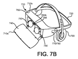
図7Aおよび図7Bは、たとえば図6のユーザが装着しているHMD600のような例示的なHMDの斜視図であり、図7Cは、たとえば図6に示されるハンドヘルド電子装置602のような例示的なハンドヘルド電子装置を示す。
7A and 7B are perspective views of an exemplary HMD, such as the HMD600 worn by the user of FIG. 6, and FIG. 7C is an exemplary example, such as the handheld
ハンドヘルド電子装置702は、装置702の内部コンポーネントが収容される筐体703と、ユーザがアクセスできる、筐体703の外側のユーザインターフェイス704とを含み得る。ユーザインターフェイス704は、ユーザタッチ入力を受信するように構成されたタッチセンシティブ面706を含み得る。ユーザインターフェイス704は、たとえば、作動ボタン、ノブ、ジョイスティックなどの、ユーザによって操作される他のコンポーネントも含み得る。いくつかの実装例では、ユーザインターフェイス704の少なくとも一部はタッチスクリーンとして構成されてもよく、ユーザインターフェイス704のその一部は、ユーザインターフェイス項目をユーザに対して表示するように、かつタッチセンシティブ面706上でユーザからのタッチ入力を受信するように構成される。ハンドヘルド電子装置702は、たとえばユーザインターフェイス704において受信したユーザ入力に応答してたとえばビームまたは光線などの光を筐体703のポートを通って選択的に放射するように構成された光源708も含み得る。
The handheld
HMD700は、フレーム720に結合された筐体710を含み得、さらに、たとえばヘッドフォンに搭載されたスピーカを含む音声出力デバイス730がフレーム720に結合されている。図7Bにおいて、筐体710の前部710aは、筐体710に収容されている部品の一部が見えるように、筐体710の基部710bから回転させられている。ディスプレイ740が、筐体710の前部710aの内部に面する側に装着されてもよい。レンズ750が、筐体710の内部において、前部710aが筐体710の基部710bに対して閉じられた位置にあるときにユーザの目とディスプレイ740との間になるように装着されてもよい。いくつかの実装例では、HMD700は、さまざまなセンサを含む検知システム760と、プロセッサ790およびHMD700の操作を容易にするさまざまな制御システム装置を含む制御システム770とを含み得る。
The
いくつかの実装例では、HMD700は、静止画および動画を撮影するカメラ780を含み得る。カメラ780が撮影した画像は、現実世界におけるユーザおよび/もしくはハンドヘルド電子装置702の物理的な位置、または仮想環境に対する物理環境の追跡を助けるために用いられてもよく、ならびに/またはユーザに対してパススルーモードでディスプレイ740に表示することで、ユーザが、HMD700を外すことなく、そうでなければHMD700の構成を変更して筐体710を動かしてユーザの視線から外すことなく、仮想環境を一時的に出て物理環境に戻ることができるようにしてもよい。
In some implementation examples, the
いくつかの実装例では、HMD700は、ユーザの目の注視を検出して追跡する注視追跡装置765を含み得る。注視追跡装置765は、たとえば瞳孔などのたとえばユーザの目の特定の部分などのユーザの目の画像を撮影して、ユーザの注視の方向および動きを検出して追跡する、たとえば1つまたは複数の画像センサ765Aを含み得る。いくつかの実装例では、HMD700は、検出された注視が、没入型仮想体験における対応する対話に変換されることになるユーザ入力として処理されるように構成され得る。
In some implementation examples, the
多数の実施形態が説明された。しかしながら、本明細書の精神および範囲から逸脱することなくさまざまな変更がなされ得ることが理解されるであろう。 A number of embodiments have been described. However, it will be appreciated that various changes can be made without departing from the spirit and scope of this specification.
加えて、図面に示される論理フローは、所望の結果を達成するために、示された特定の順序または順番を必要としない。加えて、説明されたフローに対して他のステップが提供されてもよく、またはステップが除去されてもよく、説明されたシステムに対して他のコンポーネントが追加されてもよく、または除去されてもよい。したがって、他の実施形態は以下の特許請求の範囲内にある。 In addition, the logical flows shown in the drawings do not require the particular order or order shown to achieve the desired result. In addition, other steps may be provided for the described flow, or steps may be removed, and other components may be added or removed for the described system. May be good. Therefore, other embodiments are within the scope of the following claims.
Claims (20)
仮想現実(VR)コンピュータの処理回路が、仮想環境におけるオブジェクトを生成することを備え、前記オブジェクトは、表面を有し、かつ第1の頂点を含む第1のボーンおよび第2の頂点を含む第2のボーンを含み、前記第1のボーンは、前記第1のボーンの上の点同士の間の距離を保つ剛体変換に従って前記第1の頂点の動作を定義し、前記方法はさらに、
前記第1のボーンに含まれる前記オブジェクトの前記表面の前記第1の頂点と、前記第2のボーンに含まれる前記オブジェクトの前記表面の前記第2の頂点とを動かす要求を受信することと、
前記要求に応答して、第1のフィルタを前記第1のボーンに適用し、第2のフィルタを前記第2のボーンに適用することとを備え、前記第1のフィルタおよび前記第2のフィルタの各々は、前記第1のボーンおよび前記第2のボーンにそれぞれ適用されると、前記第1のボーンの前記第1の頂点の前記動作を第1の量だけ制限し、前記第2の頂点の動作を前記第1の量とは異なる第2の量だけ減衰させる、方法。 The way
A processing circuit of a virtual reality (VR) computer comprises generating an object in a virtual environment, the object having a surface and a first bone containing a first vertex and a second vertex including a second vertex. The method further defines the behavior of the first vertex according to a rigid transformation that includes two bones, the first bone keeping a distance between points on the first bone.
Receiving a request to move the first vertex of the surface of the object contained in the first bone and the second vertex of the surface of the object contained in the second bone.
In response to the request, the first filter is applied to the first bone, the second filter is applied to the second bone, and the first filter and the second filter are provided. When applied to the first bone and the second bone, respectively, each of the first vertices of the first bone limits the movement of the first vertex by a first amount, and the second vertex A method of attenuating the operation of the above by a second amount different from the first amount.
前記動作は並進成分および回転成分を含み、
前記第1のフィルタはアイデンティティフィルタであり、前記アイデンティティフィルタは、前記第1のボーンに適用されると、前記アンカー頂点が前記剛体変換に従って経路に沿って動くように、前記アンカー頂点の前記動作の前記並進成分を減衰させる距離はゼロであり、前記アンカー頂点の前記動作の前記回転成分を減衰させる角度はゼロである、請求項1に記載の方法。 Receiving the request involves defining an anchor vertex, which is contained in the first bone.
The movement includes translational and rotational components,
The first filter is an identity filter, which, when applied to the first bone, of the movement of the anchor vertices so that the anchor vertices move along a path according to the rigid transformation. The method of claim 1, wherein the distance at which the translational component is attenuated is zero, and the angle at which the rotational component of the motion of the anchor apex is attenuated is zero.
前記方法はさらに、前記第3の領域の内部の頂点に対して変形操作を実行して、前記第3の領域の内部に変形したオブジェクトを生成することを備える、請求項2に記載の方法。 The object is a third region between a first region including the anchor vertices, a second region including the second vertices, and a first region and a second region in which the object is deformed. The second vertex is distant from the anchor vertex, including the region of
The method according to claim 2, further comprising performing a transformation operation on the vertices inside the third region to generate a deformed object inside the third region.
前記剛体変換は、座標変換のデュアルクォータニオン表現を含み、
前記方法はさらに、前記第2のフィルタを前記第2のボーンに適用した後に前記第3の領域に対してスキニング操作を実行して、前記第3の領域における前記オブジェクトのボリュームを保存することを備える、請求項3に記載の方法。 The rigid body transformation that defines the behavior of each vertex attached to one of the bones includes a dual quaternion representation of the coordinate transformations.
The method further comprises applying the second filter to the second bone and then performing a skinning operation on the third region to preserve the volume of the object in the third region. The method according to claim 3 .
前記VRコンピュータが、仮想環境におけるオブジェクトを生成することを備え、前記オブジェクトは、表面を有し、かつ第1の頂点を含む第1のボーンおよび第2の頂点を含む第2のボーンを含み、前記第1のボーンは、前記第1のボーンの上の点同士の間の距離を保つ剛体変換に従って前記第1の頂点の動作を定義し、前記方法はさらに、
前記第1のボーンに含まれる前記オブジェクトの前記表面の前記第1の頂点と、前記第2のボーンに含まれる前記オブジェクトの前記表面の前記第2の頂点とを動かす要求を受信することと、
前記要求に応答して、第1のフィルタを前記第1のボーンに適用し、第2のフィルタを前記第2のボーンに適用することとを備え、前記第1のフィルタおよび前記第2のフィルタの各々は、前記第1のボーンおよび前記第2のボーンにそれぞれ適用されると、前記第1のボーンの前記第1の頂点の前記動作を第1の量だけ減衰させ、前記第2の頂点の動作を前記第1の量とは異なる第2の量だけ減衰させる、プログラム。 A program for causing a virtual reality (VR) computer to execute a method, wherein the method is
The VR computer comprises creating an object in a virtual environment, the object comprising a first bone having a surface and containing a first vertex and a second bone containing a second vertex. The first bone defines the behavior of the first vertex according to a rigid transformation that keeps the distance between points on the first bone.
Receiving a request to move the first vertex of the surface of the object contained in the first bone and the second vertex of the surface of the object contained in the second bone.
In response to the request, the first filter is applied to the first bone, the second filter is applied to the second bone, and the first filter and the second filter are provided. When applied to the first bone and the second bone, respectively, each of the first bones attenuates the movement of the first vertex of the first bone by a first amount, and the second vertex. A program that attenuates the operation of the above by a second amount different from the first amount.
前記動作は並進成分および回転成分を含み、
前記第1のフィルタはアイデンティティフィルタであり、前記アイデンティティフィルタは、前記第1のボーンに適用されると、前記アンカー頂点が前記剛体変換に従って経路に沿って動くように、前記アンカー頂点の前記動作の前記並進成分を減衰させる距離はゼロであり、前記アンカー頂点の前記動作の前記回転成分を減衰させる角度はゼロである、請求項9に記載のプログラム。 Receiving the request involves defining an anchor vertex, which is contained in the first bone.
The movement includes translational and rotational components,
The first filter is an identity filter, which, when applied to the first bone, of the movement of the anchor vertices so that the anchor vertices move along a path according to the rigid transformation. The program according to claim 9, wherein the distance for attenuating the translational component is zero, and the angle for attenuating the rotational component of the motion of the anchor apex is zero.
前記方法はさらに、前記第3の領域の内部の頂点に対して変形操作を実行して、前記第3の領域の内部に変形したオブジェクトを生成することを備える、請求項10に記載のプログラム。 The object is a third region between a first region including the anchor vertices, a second region including the second vertices, and a first region and a second region in which the object is deformed. The second vertex is distant from the anchor vertex, including the region of
The program of claim 10, further comprising performing a transformation operation on the vertices inside the third region to generate a deformed object inside the third region.
請求項10に記載のプログラム。 Creating an object in the virtual environment includes defining the second bone as being identical to the first bone in the bind pose of the object.
The program according to claim 10.
前記方法はさらに、前記第2のフィルタを前記第2のボーンに適用した後に前記第3の領域に対してスキニング操作を実行して、前記第3の領域における前記オブジェクトのボリュームを保存することを備える、請求項11に記載のプログラム。 The rigid body transformation that defines the behavior of each vertex attached to one of the bones includes a dual quaternion representation of the coordinate transformations.
The method further comprises applying the second filter to the second bone and then performing a skinning operation on the third region to preserve the volume of the object in the third region. The program according to claim 11 .
メモリと、
前記メモリに結合される制御回路とを備え、前記制御回路は、
仮想環境におけるオブジェクトを生成するように構成され、前記オブジェクトは、表面を有し、かつ第1の頂点を含む第1のボーンおよび第2の頂点を含む第2のボーンを含み、前記第1のボーンは、前記第1のボーンの上の点同士の間の距離を保つ剛体変換に従って前記第1の頂点の動作を定義し、前記制御回路はさらに、
前記第1のボーンに含まれる前記オブジェクトの前記表面の前記第1の頂点と、前記第2のボーンに含まれる前記オブジェクトの前記表面の前記第2の頂点とを動かす要求を受信し、
前記要求に応答して、第1のフィルタを前記第1のボーンに適用し、第2のフィルタを前記第2のボーンに適用するように構成され、前記第1のフィルタおよび前記第2のフィルタの各々は、前記第1のボーンおよび前記第2のボーンにそれぞれ適用されると、前記第1のボーンの前記第1の頂点の前記動作を第1の量だけ減衰させ、前記第2の頂点の動作を前記第1の量とは異なる第2の量だけ減衰させる、VRコンピュータ。 A virtual reality (VR) computer
With memory
The control circuit includes a control circuit coupled to the memory.
Configured to generate an object in a virtual environment, the object comprises a first bone having a surface and containing a first vertex and a second bone containing a second vertex, said first. The bone defines the behavior of the first vertex according to a rigid transformation that keeps the distance between points on the first bone, and the control circuit further
Received a request to move the first vertex of the surface of the object contained in the first bone and the second vertex of the surface of the object contained in the second bone.
In response to the request, the first filter is applied to the first bone, the second filter is applied to the second bone, and the first filter and the second filter are applied. When applied to the first bone and the second bone, respectively, each of the first bones attenuates the movement of the first vertex of the first bone by a first amount, and the second vertex. A VR computer that attenuates the operation of the above by a second amount different from the first amount.
前記動作は並進成分および回転成分を含み、
前記第1のフィルタはアイデンティティフィルタであり、前記アイデンティティフィルタは、前記第1のボーンに適用されると、前記アンカー頂点が前記剛体変換に従って経路に沿って動くように、前記アンカー頂点の前記動作の前記並進成分を減衰させる距離はゼロであり、前記アンカー頂点の前記動作の前記回転成分を減衰させる角度はゼロである、請求項17に記載のVRコンピュータ。 The control circuit configured to receive the request is further configured to define anchor vertices, the anchor vertices being contained in the first bone.
The movement includes translational and rotational components,
The first filter is an identity filter, which, when applied to the first bone, of the movement of the anchor vertices so that the anchor vertices move along a path according to the rigid transformation. The VR computer according to claim 17, wherein the distance for attenuating the translational component is zero, and the angle for attenuating the rotational component of the operation of the anchor apex is zero.
前記制御回路はさらに、前記第3の領域の内部の頂点に対して変形操作を実行して、前記第3の領域の内部に変形したオブジェクトを生成するように構成される、請求項18に記載のVRコンピュータ。 The object is a third region between a first region including the anchor vertices, a second region including the second vertices, and a first region and a second region in which the object is deformed. The second vertex is distant from the anchor vertex, including the region of
18. The control circuit is further configured to perform a transformation operation on the vertices inside the third region to generate a deformed object inside the third region. VR computer.
Applications Claiming Priority (5)
| Application Number | Priority Date | Filing Date | Title |
|---|---|---|---|
| US15/463,225 | 2017-03-20 | ||
| US15/463,225 US10311621B2 (en) | 2017-03-20 | 2017-03-20 | Held object stabilization in virtual reality |
| US15/465,135 | 2017-03-21 | ||
| US15/465,135 US10162381B2 (en) | 2017-03-21 | 2017-03-21 | Hinged electronic device held in configurations by magnets |
| PCT/US2017/064146 WO2018174970A1 (en) | 2017-03-20 | 2017-12-01 | Held object stabilization in virtual reality |
Publications (2)
| Publication Number | Publication Date |
|---|---|
| JP2020509439A JP2020509439A (en) | 2020-03-26 |
| JP6793255B2 true JP6793255B2 (en) | 2020-12-02 |
Family
ID=63585691
Family Applications (1)
| Application Number | Title | Priority Date | Filing Date |
|---|---|---|---|
| JP2019524892A Active JP6793255B2 (en) | 2017-03-20 | 2017-12-01 | Stabilization of retained objects in virtual reality |
Country Status (5)
| Country | Link |
|---|---|
| EP (1) | EP3526771B1 (en) |
| JP (1) | JP6793255B2 (en) |
| KR (1) | KR102177734B1 (en) |
| CN (1) | CN109716395B (en) |
| WO (1) | WO2018174970A1 (en) |
Families Citing this family (1)
| Publication number | Priority date | Publication date | Assignee | Title |
|---|---|---|---|---|
| US12361648B2 (en) | 2022-08-26 | 2025-07-15 | Snap Inc. | Hand-tracking stabilization |
Family Cites Families (10)
| Publication number | Priority date | Publication date | Assignee | Title |
|---|---|---|---|---|
| JP3597360B2 (en) | 1997-11-17 | 2004-12-08 | 株式会社リコー | Modeling method and recording medium |
| JP3864940B2 (en) * | 2003-08-21 | 2007-01-10 | 株式会社村田製作所 | Method for measuring film strength, method for determining pass / fail of measured object having film |
| US8749556B2 (en) | 2008-10-14 | 2014-06-10 | Mixamo, Inc. | Data compression for real-time streaming of deformable 3D models for 3D animation |
| EP2362302B1 (en) * | 2010-02-26 | 2018-06-06 | Alcatel Lucent | Method for controlling motions of an object in a 3-dimensional virtual environment |
| WO2012135546A1 (en) * | 2011-03-29 | 2012-10-04 | Qualcomm Incorporated | Anchoring virtual images to real world surfaces in augmented reality systems |
| US8897491B2 (en) * | 2011-06-06 | 2014-11-25 | Microsoft Corporation | System for finger recognition and tracking |
| US9214036B1 (en) | 2012-06-26 | 2015-12-15 | Pixar | Animation engine for blending computer animation data |
| JP6391465B2 (en) * | 2014-12-26 | 2018-09-19 | Kddi株式会社 | Wearable terminal device and program |
| JPWO2016157951A1 (en) * | 2015-03-31 | 2018-01-25 | ソニー株式会社 | Display control device, display control method, and recording medium |
| WO2017027957A1 (en) | 2015-08-17 | 2017-02-23 | Side Effects Software Inc. | Physically based simulation methods for modeling and animating two- and three-dimensional deformable objects |
-
2017
- 2017-12-01 JP JP2019524892A patent/JP6793255B2/en active Active
- 2017-12-01 EP EP17818380.2A patent/EP3526771B1/en active Active
- 2017-12-01 KR KR1020197010867A patent/KR102177734B1/en active Active
- 2017-12-01 WO PCT/US2017/064146 patent/WO2018174970A1/en not_active Ceased
- 2017-12-01 CN CN201780058201.9A patent/CN109716395B/en active Active
Also Published As
| Publication number | Publication date |
|---|---|
| EP3526771B1 (en) | 2021-02-24 |
| EP3526771A1 (en) | 2019-08-21 |
| KR102177734B1 (en) | 2020-11-12 |
| JP2020509439A (en) | 2020-03-26 |
| KR20190047723A (en) | 2019-05-08 |
| WO2018174970A1 (en) | 2018-09-27 |
| CN109716395B (en) | 2023-09-15 |
| CN109716395A (en) | 2019-05-03 |
Similar Documents
| Publication | Publication Date | Title |
|---|---|---|
| JP6820405B2 (en) | Manipulating virtual objects with 6DOF controllers in extended and / or virtual reality environments | |
| JP6929361B2 (en) | Input controller stabilization technology for virtual reality systems | |
| CN111771180B (en) | Mixed placement of objects in augmented reality environments | |
| JP7008730B2 (en) | Shadow generation for image content inserted into an image | |
| JP6782846B2 (en) | Collaborative manipulation of objects in virtual reality | |
| US10636222B2 (en) | Avatars in virtual environments | |
| WO2020072591A1 (en) | Placement and manipulation of objects in augmented reality environment | |
| US20170329503A1 (en) | Editing animations using a virtual reality controller | |
| US20230351710A1 (en) | Avatar State Versioning for Multiple Subscriber Systems | |
| US11610376B1 (en) | Wrist-stabilized projection casting | |
| US20240281070A1 (en) | Simultaneous Controller and Touch Interactions | |
| WO2024144989A1 (en) | Streaming native application content to artificial reality devices | |
| CN108700944B (en) | System and method related to motion in a virtual reality environment | |
| US10311621B2 (en) | Held object stabilization in virtual reality | |
| JP6793255B2 (en) | Stabilization of retained objects in virtual reality | |
| US12547237B1 (en) | Artificial reality input for two-dimensional virtual objects | |
| US20250322599A1 (en) | Native Artificial Reality System Execution Using Synthetic Input | |
| WO2023212349A1 (en) | Avatar state versioning for multiple devices | |
| WO2024091371A1 (en) | Artificial reality input for two-dimensional virtual objects | |
| WO2024072595A1 (en) | Translating interactions on a two-dimensional interface to an artificial reality experience | |
| KR20240126840A (en) | Motion dependent display | |
| Tecchia et al. | Addressing the problem of Interaction in fully Immersive Virtual Environments: from raw sensor data to effective devices |
Legal Events
| Date | Code | Title | Description |
|---|---|---|---|
| A521 | Request for written amendment filed |
Free format text: JAPANESE INTERMEDIATE CODE: A523 Effective date: 20190822 |
|
| A621 | Written request for application examination |
Free format text: JAPANESE INTERMEDIATE CODE: A621 Effective date: 20190822 |
|
| A977 | Report on retrieval |
Free format text: JAPANESE INTERMEDIATE CODE: A971007 Effective date: 20200917 |
|
| TRDD | Decision of grant or rejection written | ||
| A01 | Written decision to grant a patent or to grant a registration (utility model) |
Free format text: JAPANESE INTERMEDIATE CODE: A01 Effective date: 20201013 |
|
| A61 | First payment of annual fees (during grant procedure) |
Free format text: JAPANESE INTERMEDIATE CODE: A61 Effective date: 20201109 |
|
| R150 | Certificate of patent or registration of utility model |
Ref document number: 6793255 Country of ref document: JP Free format text: JAPANESE INTERMEDIATE CODE: R150 |
|
| R250 | Receipt of annual fees |
Free format text: JAPANESE INTERMEDIATE CODE: R250 |
|
| R250 | Receipt of annual fees |
Free format text: JAPANESE INTERMEDIATE CODE: R250 |
|
| R250 | Receipt of annual fees |
Free format text: JAPANESE INTERMEDIATE CODE: R250 |